SlideShare a Scribd company logo
Practical	
  Firmware	
  Reversing	
  
and	
  Exploit	
  Development	
  for	
  
AVR-­‐based	
  Embedded	
  Devices	
  
Alexander	
  @dark_k3y	
  Bolshev
Boris	
  @dukeBarman Ryutin
Agenda
Part	
  1:	
  Quick	
  RJMP to	
  AVR	
  +	
  Introduction	
  
example
Part	
  2:	
  Pre-­‐exploitation
Part	
  3:	
  Exploitation	
  and	
  ROP-­‐chains	
  building
Part	
  4:	
  Post-­‐exploitation	
  and	
  tricks
Thus:	
  If	
  you	
  have	
  
a	
  question,	
  please	
  
interrupt and	
  ask	
  
immediately
Disclaimer:
1)	
  Training	
  is	
  VERY fast-­‐paced
2)	
  Training	
  is	
  highly-­‐practical
3)	
  You	
  may	
  encounter	
  information	
  overflow
4)	
  My	
  English	
  is	
  far	
  from	
  perfect
Image Credit: Marac Kolodzinski
Part	
  1:	
  What	
  is	
  AVR?
AVR
• Alf	
  (Egil Bogen)	
  and	
  Vegard (Wollan)’s	
  RISC	
  processor
• Modified	
  Harvard	
  architecture	
  8-­‐bit	
  RISC	
  single-­‐chip	
  microcontroller	
  
• Developed	
  by	
  Atmel	
  in	
  1996	
  (now	
  Dialog/Atmel)
Image: https://de.wikipedia.org/wiki/Atmel AVR
AVR	
  is	
  almost	
  everywhere	
  
• Industrial	
  PLCs	
  and	
  gateways
• Home	
  electronics:	
  kettles,	
  irons,	
  weather	
  stations,	
  etc
• IoT
• HID	
  devices	
  (ex.:	
  Xbox	
  hand	
  controllers)
• Automotive	
  applications:	
  security,	
  safety,	
  powertrain	
  and	
  entertainment	
  
systems.	
  
• Radio	
  applications	
  (and	
  also	
  Xbee and	
  Zwave)
• Arduino	
  platform	
  
• WirelessHART transmitters	
  and	
  sensors
• Your	
  new	
  shiny	
  IoE fridge ;-­‐)
AVR	
  inside	
  industrial	
  gateway
Synapse	
  IoT module	
  with	
  Atmega128RFA1	
  inside	
  
Philips	
  Hue	
  Bulb
http://www.eetimes.com/document.asp?doc_id=1323739&image_number=1
AVR	
  inside	
  home	
  automation	
  dimmer	
  
Harvard	
  Architecture
Harvard	
  Architecture
• Physically	
  separated	
  storage	
  and	
  signal	
  pathways	
  for	
  instructions	
  and	
  
data	
  
• Originated	
  from	
  the	
  Harvard	
  Mark	
  I	
  relay-­‐based	
  computer	
  
Image: https://en.wikipedia.org/wiki/Harvard architecture
Modified	
  Harvard	
  architecture…
…allows	
  the	
  contents	
  of	
  the	
  instruction	
  memory	
  to	
  be	
  accessed	
  as	
  if	
  it	
  
were	
  data1
1but not the data as code!
Introduction	
  example:
We’re	
  still	
  able	
  to	
  exploit!
AVR	
  “features”
AVR-­‐8
• MCU	
  (MicroController Unit)	
  -­‐-­‐ single	
  computer	
  chip	
  designed	
  for	
  
embedded	
  applications
• Low-­‐power
• Integrated	
  RAM	
  and	
  ROM	
  (SRAM	
  +	
  EEPROM	
  +	
  Flash)
• Some	
  models	
  could	
  work	
  with	
  external	
  SRAM
• 8-­‐bit,	
  word	
  size	
  is	
  16	
  bit	
  (2	
  bytes)
• Higher	
  integration	
  
• Single	
  core/Interrupts
• Low-­‐freq (<20MHz	
  in	
  most	
  cases)
Higher	
  Integration
• Built-­‐in	
  SRAM,	
  EEPROM	
  an	
  Flash
• GPIO	
  (discrete	
  I/O	
  pins)
• UART(s)
• I2C,	
  SPI,	
  CAN,	
  …
• ADC
• PWM	
  or	
  DAC
• Timers
• Watchdog
• Clock	
  generator	
  and	
  divider(s)
• Comparator(s)
• In-­‐circuit	
  programming	
  and	
  debugging	
  support
AVRs	
  are	
  very	
  different
• AtTiny13
• Up	
  to	
  20	
  MIPS	
  Througput at	
  20	
  MHz
• 64	
  SRAM/64	
  EEPROM/1k	
  Flash
• Timer,	
  ADC,	
  2	
  PWMs,	
  Comparator,	
  
internal	
  oscillator
• 0.24mA	
  in	
  active	
  mode,	
  0.0001mA	
  in	
  
sleep	
  mode
AVRs	
  are	
  very	
  different
• Atmega32U4
• 2.5k	
  SRAM/1k	
  EEPROM/32k	
  Flash
• JTAG
• USB
• PLL,	
  Timers,	
  PWMs,	
  Comparators,	
  
ADCs,	
  UARTs,	
  Temperatures	
  sensors,	
  
SPI,	
  I2C,	
  …	
  =>	
  tons	
  of	
  stuff
AVRs	
  are	
  very	
  different
• Atmega128
• 4k	
  SRAM/4k	
  EEPROM/128k	
  Flash
• JTAG
• Tons	
  of	
  stuff…
The	
  workshop	
  focuses	
  on	
  this	
  chip
Why	
  Atmega128?
• Old,	
  but	
  very	
  widespread	
  chip	
  
• At90can128	
  – popular	
  analogue	
  for	
  CAN	
  buses	
  in	
  automotive	
  
application
• Cheap	
  JTAG	
  programmer
• Much	
  SRAM	
  ==	
  ideal	
  for	
  ROP-­‐chain	
  construction	
  training
Let’s	
  look	
  to	
  the	
  architecture	
  of	
  Atmega128…
Practical reverse engineering and exploit development for AVR-based Embedded Devices (s4x16)
Ok,	
  ok,	
  let’s	
  simplify	
  a	
  bit	
  J
Image:	
  http://www.cs.jhu.edu/~jorgev/cs333/usbkey/uC_3.JPG
Note:	
  code	
  is	
  separated from	
  data
Memory	
  map
Memory:	
  registers	
  
• R0-­‐R25	
  – GPR
• X,Y,Z	
  – pair	
  “working”	
  
registers,	
  e.g.	
  for	
  memory	
  
addressing	
  operations
• I/O	
  registers	
  – for	
  accessing	
  
different	
  “hardware”
Memory:	
  special	
  registers
• PC	
  – program	
  counter,	
  16-­‐bit	
  register
• SP	
  – stack	
  pointer,	
  16-­‐bit	
  register	
  (SPH:SPL)
• SREG	
  – status	
  register	
  (8-­‐bit)
Memory	
  addressing
• SRAM/EEPROM	
  – 16-­‐bit	
  addressing,	
  8-­‐bit	
  element
• Flash	
  – 16(8)-­‐bit	
  addressing,	
  16-­‐bit	
  element
LPM	
  
command!
Memory	
  addressing	
  directions
• Direct	
  to	
  register
• Direct	
  to	
  I/O
• SRAM	
  direct
• SRAM	
  indirect (pre-­‐ and	
  post-­‐ increment)
• Flash	
  direct	
  
Datasheets	
  are	
  your	
  best	
  friends!
Practical reverse engineering and exploit development for AVR-based Embedded Devices (s4x16)
Interrupts
• Interrupts	
  interrupt	
  normal	
  process	
  
of	
  code	
  execution	
  for	
  handling	
  
something	
  or	
  reacting	
  to	
  some	
  event
• Interrupt	
  handler	
  is	
  a	
  procedure	
  to	
  
be	
  executed	
  after	
  interrupt;	
  address	
  
stored	
  in	
  the	
  interrupt	
  vector
• Examples	
  of	
  interrupts:
- Timers
- Hardware	
  events
- Reset
AVR	
  assembly
Very	
  
quickly
Instruction	
  types
• Arithmetic	
  and	
  logic
• Bit	
  manipulation/test
• Memory	
  manipulation
• Unconditional	
  jump/call
• Branch	
  commands
• SREG	
  manipulation
• Special	
  (watchdog,	
  etc)
Instruction	
  mnemonics
mov r16,r0 ; Copy r0 to r16
out PORTA, r16 ; Write r16 to PORTA
16-­‐bit	
  long
“Intel	
  syntax”	
  (destination	
  before source)
A	
  bit	
  more	
  about	
  architecture
Fuses	
  and	
  Lock	
  Bits
• Several bytes of permanent storage
• Set internal hardware and features
configuration, including oscillator
(int or ext), bootloader, pins, ability
to debug/program, etc.
• 2 lock bits controls programming
protection.
AVR	
  bootloader – what	
  is	
  it?
• Part	
  of	
  code	
  that	
  starts	
  BEFORE RESET	
  interrupt.
• Could	
  be	
  used	
  for	
  self-­‐programmable	
  (i.e.	
  without	
  external	
  device)	
  
systems,	
  in	
  case	
  you	
  need	
  	
  update	
  the	
  firmware	
  of	
  your	
  IoT device.
• Bootloader address	
  and	
  behavior	
  configured	
  via	
  FUSEs.
• BLB	
  lock	
  bits	
  controls	
  bootloader ability	
  to	
  update	
  application	
  and/or	
  
bootloader parts	
  of	
  flash.
AVR	
  bootloaders
• Arduino	
  bootloader
• USB	
  bootloaders (AVRUSBBoot)
• Serial	
  programmer	
  bootloaders (STK500-­‐compatible)
• Cryptobootloaders
• …
• Tons	
  of	
  them!
Watchdog
• Timer	
  that	
  could	
  be	
  used	
  to	
  interrupt	
  or	
  reset	
  device.
• Cleared	
  with	
  WDR instruction.
http://ardiri.com/blog/entries/20141028/watchdog.jpg
Development	
  for	
  AVR
Atmel	
  studio
AVR-­‐GCC
• Main	
  compiler/debugger	
  kit	
  for	
  the	
  platform
• Used	
  by	
  Atmel	
  studio
• Use	
  “AVR	
  libc”	
  -­‐-­‐ http://www.nongnu.org/avr-­‐libc/	
  
• Several	
  optimization	
  options,	
  several	
  memory	
  models
Other	
  tools
• Arduino
• CodeVision AVR
• IAR	
  Embedded	
  workbench
Debugging	
  AVR
JTAG
• Joint	
  Test	
  Action	
  Group	
  (JTAG)
• Special	
  debugging	
  interface	
  added	
  to	
  a	
  chip
• Allows	
  testing,	
  debugging,	
  	
  firmware	
  manipulation	
  and	
  boundary	
  
scanning.
• Requires	
  external	
  hardware
JTAG	
  for	
  AVRs
AVR	
  JTAG	
  mkI
AVR	
  JTAG	
  mkII
AVR	
  Dragon
AVR	
  JTAGIce3
Atmel	
  ICE3
Avarice
• Open-­‐source	
  interface	
  between	
  AVR	
  JTAG	
  and	
  GDB	
  
• Also	
  allow	
  to	
  flash/write	
  EEPROM,	
  manipulate	
  fuse	
  and	
  lock	
  bits.
• Could	
  capture the	
  execution	
  flow	
  to	
  restore	
  the	
  firmware
• Example	
  usage:
avarice --program --file test.elf --part atmega128 --jtag /dev/ttyUSB0 -d :4242
AVR-­‐GDB
• Part	
  of	
  “nongnu”	
  AVR	
  gcc kit.
• Roughly	
  ported	
  standard	
  gdb to	
  AVR	
  platform
• Doesn’t	
  understand	
  Harvard	
  architecture
- You	
  will	
  need	
  to	
  resolve	
  memory	
  address	
  by	
  reference	
  of	
  $pc	
  to	
  read	
  the	
  
flash	
  
(gdb) x/10b $pc + 100
Simulators
• Atmel	
  Studio	
  simulator
• Proteus	
  simulator
• Simavr
• Simulavr
Training	
  kit	
  content
AVR	
  JTAG	
  mkI
Atmega128	
  custom
devboard
ESP8266	
  “WiFi to	
  serial”
Arduino
VM	
  access:
Login:	
  radare
Password:	
  radare
cd /home/radare/workshop/ex1.1
avarice --mkI --jtag /dev/ttyUSB0 -p -e --file hello.hex
Communication: CuteCom or Ccreen /dev/ttyUSB1 9600
For	
  debugging:
avarice --mkI --jtag /dev/ttyUSB0 -p -e --file hello.hex -d :4242
In	
  new	
  terminal	
  window:
avr-gdb
(gdb) target remote :4242
Ex	
  1.1:	
  Hello	
  world!
Simulator
cd /home/radare/workshop/ex1.1_simulator
simulavr -d atmega128 -f hello.elf -F 16000000 -x -,E1,9600 -y -,E0,9600
For	
  debugging:
simulavr -d atmega128 -f hello.elf -F 16000000 -x -,E1,9600 -y -,E0,9600 -g
avr-gdb
(gdb) target remote :1212
Ex	
  1.1_simulator:	
  Hello	
  world!
cd /home/radare/workshop/ex1.2
avarice --mkI --jtag /dev/ttyUSB0 -p -e --file blink.hex
For	
  debugging:
avarice --mkI --jtag /dev/ttyUSB0 -p -e --file blink.hex -d :4242
avr-gdb
(gdb) target remote :4242
Ex	
  1.2:	
  Blink!
Part	
  2:	
  Pre-­‐exploitation
You	
  have	
  a	
  device.	
  First	
  steps?
Decide	
  
what	
  you	
  
want
Determine	
  
target	
  
platform
Search	
  for	
  
I/O	
  
point(s)
Search	
  for	
  
debug	
  
point(s)
Acquire	
  
the	
  
firmware
Fuzz	
  
and/or	
  
static	
  
analysis
Let’s	
  start	
  with	
  a	
  REAL	
  example
• Let’s	
  use	
  training	
  kit	
  board	
  as	
  an	
  example	
  
• Imagine	
  that	
  you	
  know	
  nothing	
  about	
  it
• We	
  will	
  go	
  through	
  all	
  steps,	
  one	
  by	
  one
What	
  we	
  want?
To	
  start	
  with,	
  decide	
  what	
  you	
  want:
• Abuse	
  of	
  functionality
• Read	
  something	
  from	
  EEPROM/Flash/SRAM
• Stay	
  persistent
Complexity
Determine	
  target	
  platform
• Look	
  at	
  the	
  board	
  and	
  search	
  for	
  all	
  ICs…
Atmega128	
  16AU
CP2102
ESP8266EX
Digikey/Octopart/Google…
Search	
  for	
  I/O(s)
USB
Antenna
UART
External	
  connectors
External	
  connectors
Search	
  for	
  I/O(s):	
  tools
Jtagulator
Bus	
  pirate Saleae logic	
  analyzer Arduino
Search	
  for	
  debug	
  interface(s)
ISP
JTAG
Search	
  for	
  debug	
  interface(s):	
  tools
Jtagulator Arduino+	
  JTAGEnum
Or	
  cheaper
JTAGEnum against	
  
Atmega128	
  demoboard
• Connect	
  Arduino	
  to	
  Atmega128	
  demoboard
• Connect	
  Arduino	
  to	
  PC	
  with	
  USB	
  cable
cd ~/workshop/JTAGenum
make upload (click	
  reset	
  on	
  arduino just	
  before	
  it)
screen /dev/ttyACM0 115200
• Press	
  “s”
Search	
  for	
  debug	
  &	
  I/O:	
  real	
  device
Ethernet
Button
LEDs
Connector ICS	
  bus
2	
  JTAGs
ISPs
Acquire	
  the	
  firmware
• From	
  vendor	
  web-­‐site	
  J
• Sniffing	
  the	
  firmware	
  update	
  session
• From	
  device	
  itself
Acquiring	
  the	
  firmware:	
  sniff	
  it!
Acquiring	
  the	
  firmware:	
  JTAG	
  or	
  ISP
• Use	
  JTAG	
  or	
  ISP	
  programmer	
  to	
  connect	
  to	
  the	
  board	
  debug	
  ports
• Use:
- Atmel	
  Studio
- AVRDude
- Programmer-­‐specific	
  software	
  to	
  read	
  flash
$ avrdude -p m128 -c jtag1 –P /dev/ttyUSB0 
-U flash:r:"/home/avr/flash.bin":r
Acquiring	
  the	
  firmware:	
  lock	
  bits
• AVR	
  has	
  lock	
  bits	
  that	
  protect	
  device	
  from	
  extracting	
  flash
• Clearing	
  these	
  lockbits will	
  erase	
  the	
  entire	
  device
• If	
  you	
  have	
  them	
  set	
  you’re	
  not	
  lucky -­‐-­‐>	
  try	
  to	
  get	
  firmware	
  from	
  other	
  
sources	
  
• However,	
  if	
  you	
  have	
  lock	
  bits	
  set	
  but	
  JTAG	
  is	
  enabled you	
  could	
  try	
  partial	
  
restoration	
  of	
  firmware	
  with	
  avarice	
  –capture	
  (rare	
  case)
Read	
  fuses	
  and	
  lock	
  bits	
  using	
  
avarice --mkI --jtag /dev/ttyUSB0 –r -l
Exercise	
  2.0:	
  Fuses
Firmware	
  reversing:	
  formats
• Raw	
  binary	
  format
• ELF	
  format	
  for	
  AVRs
• Intel	
  HEX	
  format	
  (often	
  used	
  by	
  programmers)
• Could	
  be	
  easily	
  converted	
  between	
  with	
  avr-­‐objcopy,	
  e.g.:
avr-objcopy -I ihex -O binary blink.hex blink.bin
AVR	
  RE
Reverse	
  engineering	
  AVR	
  binaries
Pure	
  disassemblers:
• avr-­‐objdump – gcc kit	
  standard	
  tool
• Vavrdisasm -­‐-­‐ https://github.com/vsergeev/vavrdisasm
• ODAweb -­‐-­‐ https://www.onlinedisassembler.com/odaweb/	
  
“Normal”	
  disassemblers:
• IDA	
  Pro
• Radare
IDA	
  PRO:	
  AVR	
  specifics
• Incorrect	
  AVR	
  elf-­‐handling
• Incorrect	
  LPM	
  command	
  behavior
• Addressing	
  issues
• Sometimes	
  strange	
  output
...
• Still	
  usable,	
  but	
  “with	
  care”
Radare2
• Opensourcereverse	
  engineering	
  framework	
  (RE,	
  debugger,	
  forensics)
• Crossplatform (Linux,Mac,Windows,QNX,Android,iOS,	
  …)
• Scripting
• A	
  lot	
  of	
  architectures	
  /	
  file-­‐formats
• …
• Without	
  “habitual”	
  GUI	
  (c)	
  pancake	
  
Radare2:	
  Tools
• radare2
• rabin2
• radiff2
• rafind2
• rasm2
• r2pm
• rarun2
• rax2
• r2agent
• ragg2
• rahash2
• rasign2
Radare2:	
  Usage
• Install	
  from	
  git
#	
  git clone	
  https://github.com/radare/radare2
#	
  cd	
  radare2
#	
  sys/install.sh
• Packages	
  (yara,	
  retdec /	
  radeco decompilers,	
  …):
#	
  r2pm	
  -­‐i radare2
• Console	
  commands
#	
  r2	
  -­‐d	
  /bin/ls	
  – debugging
#	
  r2	
  –a	
  avr sample.bin – architecture
#	
  r2	
  –b	
  16	
  sample.bin – specify	
  register	
  size	
  in	
  bits
#	
  r2	
  sample.bin –i script	
  – include	
  script
Radare2:	
  Basic	
  commands
• aaa – analyze
• axt – xrefs
• s	
  – seek
• p	
  – disassemble
• ~	
  -­‐ grep
• !	
  – run	
  shell	
  commands
• /	
  – search
• /R	
  – search	
  ROP
• /c	
  – search	
  instruction
• ?	
  – help
Radare2:	
  Disassembling
• p?
• pd/pD -­‐ dissamble
• pi/pI – print	
  instructions
• Examples:
>	
  pd 35	
  @	
  function
Radare2:	
  Options
• ~/.radarerc
• e	
  asm.describe=true
• e	
  scr.utf8=true
• e	
  asm.midflags=true
• e	
  asm.emu=true
• eco	
  solarized
Radare2:	
  Interfaces
• ASCII	
  – VV
• Visual	
  panels	
  – V!	
  (vim	
  like	
  controls)
• Web-­‐server	
  – r2	
  -­‐c=H	
  file
• Bokken	
  
Best	
  combinations	
  for	
  AVR	
  RE
• Both	
  Radare2	
  and	
  IDA	
  Pro	
  have	
  pitfalls	
  when	
  working	
  with	
  AVR
• That’s	
  why	
  I am	
  using	
  the	
  following	
  combination
IDA	
  Pro	
  6.6+	
  +	
  Radare2	
  +	
  GDB	
  +	
  avr-­‐objdump
Here	
  we	
  will	
  focus	
  on	
  Radare2	
  +	
  GDB,	
  because	
  not	
  everyone	
  can	
  afford	
  
latest	
  IDA	
  Pro	
  L
cd /home/radare/workshop/ex2.1
avr-objcopy –I ihex –O binary hello.hex hello.bin
r2 –a avr hello.bin
Ex	
  2.1:	
  Hello!	
  RE
Now	
  we	
  will	
  scrutinize	
  every
line of	
  disassembled	
  code.
Boring,	
  but	
  is	
  required	
  for	
  further	
  
understanding
http://reallycuteanimals.co.uk/wp-­‐content/uploads/2012/06/120519-­‐cat-­‐keyboard_thumb.jpg
Interrupts	
  vector	
  &&	
  init sectionInterrupts	
  vector
main()	
  à
Program	
  halt
Initsection
Memory	
  manipulation:	
  stack	
  push
push r14 ; save r14 on the Stack
SP	
  =	
  SP	
  -­‐ 1
Some	
  value
Some	
  value
0x10
Some	
  value
Some	
  valueSP
push	
  r14
r14 = 0x10
Memory	
  manipulation:	
  stack	
  pop
push r14 ; save r14 on the Stack
pop r15 ; pop top of Stack to r15
SP	
  =	
  SP	
  -­‐ 1
SP	
  =	
  SP	
  +	
  1
Some	
  value
Some	
  value
0x10
Some	
  value
Some	
  valueSP
push	
  r14
Some	
  value
Some	
  value
0x10
pop	
  r15
SP
Some	
  value
Some	
  value
r15 ß 0x10
r14 = 0x10
Unconditional	
  jump/call
jmp 0xABC1 ; PC = 0xABC1
rjmp 5 ; PC = PC + 5 + 1
call 0xABC1 ; “push PC+2”
; jmp 0xABC1
ret ; “pop PC”
Harvard	
  architecture?	
  But	
  PC	
  goes	
  to	
  DATA	
  
memory
Arithmetic	
  instructions
add r1,r2 ; r1 = r1 + r2
add r28,r28 ; r28 = r28 + r28
and r2,r3 ; r2 = r2 & r3
clr r1 ; r1 = 0
ser r28 ; r28 = 0xFF
inc r0 ; r0 = r0 + 1
neg r0 ; r0 = -r0
…
Memory	
  manipulation:	
  immediate	
  values
ldi r29, 0x10 ; r29 = 0x10
Memory	
  manipulation:	
  ports
in r15, $16 ; r15 = PORTB
out $16, r0 ; PORTB = r0
What	
  is	
  the	
  0x3f,	
  0x3e,	
  0x3d	
  and	
  where	
  to	
  find	
  them?
Datasheets	
  are	
  your	
  best	
  friends!	
  (2)
P.	
  366	
  of	
  Atmega128L	
  datasheet
So,	
  what’s	
  going	
  on	
  here?
1
2
3
1. SREG	
  (Status	
  REGister)	
  is	
  cleared	
  (set	
  to	
  r1	
  value,	
  which	
  is	
  0x00)
2. SPL	
  ß r28	
  (0xFF)
3. SPH	
  ß r29	
  (0x10)	
  
After	
  init:
SREG	
  =	
  0,	
  SP	
  =	
  0x10FF	
  =	
  4351(SRAM	
  limit)
Going	
  further
Memory	
  manipulation:	
  lds/sts
lds r2,0xFA00 ; r2 = *0xFA00
sts 0xFA00,r0 ; *0xFA00 = r0
Here:
1. *0x98 ß r1 (0x00)
2. r24 ß 0x67
3. *0x99 ß r24 (0x67)
Datasheets	
  are	
  your	
  best	
  friends!	
  (3)
P.	
  365	
  of	
  Atmega128L	
  datasheet
What	
  is	
  it	
  all	
  about	
  and	
  why	
  sts and	
  not	
  out?
UBRR1H	
  =	
  (	
  BAUD_PRESCALE	
  >>	
  8)	
  ;	
  	
  
10929800 sts 0x0098, r1
UBRR1L	
  	
  =	
  (	
  BAUD_PRESCALE	
  )	
  ;	
  	
  
87e6 ldi r24, 0x67
80939900 sts 0x0099, r24
• Registers	
  are	
  also	
  part	
  of	
  the	
  RAM
• Common	
  rule:	
  
- Every	
  IO/RAM	
  address	
  is	
  reachable	
  with	
  sts/lds while	
  in/out are	
  used	
  for	
  	
  
(0x00	
  -­‐ 0x3F	
  range)
Why	
  0x0067?
• USART	
  is	
  clocking	
  from	
  internal	
  generator	
  (16MHz	
  in	
  our	
  case)
• We	
  selected	
  baud	
  speed	
  of	
  9600
• The	
  common	
  formula	
  of	
  USART	
  frequency	
  divider	
  for	
  AVR	
  (see	
  
datasheet	
  for	
  USART	
  section,	
  p.194+):
BAUD_PRESCALE	
  =	
  	
  (F_CPU	
  /	
  (USART_BAUDRATE	
  *	
  16))	
  – 1	
  =
=	
  16	
  000	
  000	
  /	
  (9600	
  *	
  16)	
  – 1	
  =	
  104.1666666(6)	
  – 1	
  ~=	
  103	
  =	
  0x0067
More	
  arithmetic	
  instructions
andi r2, 0x10 ; r2 = r2 & 0x10
ori r24, 0x98 ; r24 = r24 | 0x98
…
UCSR1B |= (1 << RXEN1) | (1 << TXEN1) | (1 << RXCIE1);
Enables	
  RX	
  and	
  TX	
  lines,	
  enable	
  RX	
  interrupt.
UCSR1C |= (1<<USBS1) | (3<<UCSZ10);
Set	
  stop	
  bit	
  and character	
  size	
  
Functions	
  &&	
  Calling	
  conventions
send_byte('H');
Typical	
  AVR	
  calling	
  convention	
  for	
  arguments	
  
• Call-­‐used:	
  R18–R27,	
  R30,	
  R31
• Call-­‐saved:	
  R2–R17,	
  R28,	
  R29
• R29:R28	
  used	
  as	
  frame	
  pointer
We	
  will	
  discuss	
  it	
  in	
  more	
  details	
  later.
_delay_ms(1000);
This	
  “function”	
  is	
  inlined as:
subi r18,0x01 ; r18 = r18 – 1
sbci r24,0x00 ; r24 = r24 – 0 – C
; C – Carry flag from arithmetic operations (SREG)
Conditional	
  jump
cpse r1, r0 ; r1 == r2 ?
PC ← PC + 2 : PC ← PC + 3
breq 10 ; Z ? PC ← PC + 1 + 10
brne -4 ; !Z ? PC ← PC + 1 - 4
…
Why	
  -­‐4?
f7e1 =	
  1111	
  0111	
  1110	
  0001	
  
11	
  1110	
  0	
  in	
  two’s	
  complement	
  form	
  ==	
  -­‐4
Special
• break – debugger	
  break
• nop – no	
  operation
• sleep – enter	
  sleep	
  mode
• wdr – watchdog	
  timer	
  reset
void	
  send_byte(uint8_t	
  byte)
while((UCSR1A	
  &(1<<UDRE1))	
  ==	
  0);
UDR1	
  =	
  byte;
Conditional	
  “skip”
sbrc r0, 7 ; skip if bit 7 in r0 cleared
cpse r4,r0 ; skip if r4 == r0
sbrs r25,5 ; skip if bit 5 in r25 set
More	
  things	
  to	
  know
Comparison
cp r4,r19 ; Compare r4 with r19
brne label1 ; jump if r19 != r4
; Compare r3:r2 with r1:r0
cp r2,r0 ; Compare low byte
cpc r3,r1 ; Compare high byte
brne label2 ; jump if r3:r2 != r1:r0
cpi r19,3 ; Compare r19 with 3
brne label3 ; jump if r19 != 3
SREG	
  – 8-­‐bit	
  status	
  register
C – Carry flag
Z – Zero flag
N – Negative flag
V – two’s complement oVerflow indicator
S – N ⊕ V, for Signed tests
H – Half carry flag
T – Transfer bit (BLD/BST)
I – global Interrupt enable/disable flag
SREG	
  manipulations
• sec/clc – set/clear	
  carry
• sei/cli – set/clear	
  global	
  interruption	
  flag
• se*/cl* – set/clear	
  *	
  flag	
  in	
  SREG
More	
  memory	
  manipulation
mov r1, r2 ; r1 = r2
st Z, r0 ; *Z(r31:r30) = r0
st –Z, r1 ; *Z-- = r1
std Z+5, r2 ; *(Z+5) = r2
…
Same	
  
for	
  LD*
Indirect
Direct
Memory	
  manipulation:	
  flash
lpm r16, Z ; r16 = *(r31:r30), but from flash
Note:	
  code	
  is	
  separated from	
  data
Bit	
  manipulation	
  instructions
sbr r16, 3 ; set bits 0 and 1 in r16
lsl r0 ; r0 << 2
lsr r1 ; r1 >> 2
rol r15 ; cyclic shift r16 bits to the
left
ror r16 ; cyclic shift r16 bits to the
right
cbr r18,1 ; clear bit 1 in r18
cbi $16, 1 ; PORTB[1] = 0
cd /home/radare/workshop/ex2.2
avr-objcopy –I ihex –O binary blink.hex blink.bin
r2 –a avr blink.bin
Ex	
  2.2:	
  Blink!	
  RE
Questions:
1. Identify	
  main()	
  function,	
  define	
  and	
  rename	
  it
2. Find	
  the	
  LED	
  switching	
  command
3. What	
  type	
  of	
  delay	
  is	
  used	
  and	
  why	
  accuracy	
  of	
  MCU	
  frequency	
  important?
4. Locate	
  interrupt	
  vector	
  and	
  init code,	
  explain	
  what	
  happens	
  inside	
  init code
Reversing:	
  function	
  szignatures
• Majority	
  of	
  firmware	
  contains	
  zero	
  or	
  little	
  strings.
• How	
  to	
  start?
• Use	
  function	
  signatures.
• However,	
  in	
  AVR	
  world	
  signatures	
  may	
  be	
  to	
  vary.
• Be	
  prepared	
  to	
  guess	
  target	
  compiler/library/RTOS	
  and	
  options…	
  or	
  
bruteforceit.
• In	
  R2,	
  signatures	
  are	
  called	
  zignatures.
Working	
  with	
  zignatures
Embedded	
  code	
  priorities
• Size
• Speed
• Hardware	
  limits
• Redundancy
• …
• …
• …
• …
• Security
Fuzzing specifics
• Fuzzing	
  is	
  a	
  fuzzing.	
  Everywhere.
• But…	
  we’re	
  in embedded	
  world
• Sometimes	
  you	
  can detect	
  crash	
  through	
  test/debug	
  UART	
  or	
  pins
• In	
  most	
  cases,	
  you	
  can	
  detect	
  crash	
  only	
  by	
  noticing	
  that	
  device	
  is	
  no	
  
longer	
  response
• Moreover,	
  watchdog	
  timer can	
  limit	
  your	
  detection	
  capabilities	
  by	
  
resetting	
  the	
  device
• So	
  how	
  to	
  detect	
  crash?
Fuzzing:	
  ways	
  to	
  detect	
  crash
• JTAG	
  debugger	
  – break	
  on	
  RESET
• External	
  analysis	
  of	
  functionality	
  – detect	
  execution	
  pauses
• Detect	
  bootloader/initialization	
  code	
  (e.g.	
  for	
  SRAM)	
  behavior	
  with	
  
logic	
  analyzer	
  and/or	
  FPGA
• Detect	
  power	
  consumption	
  change	
  with	
  oscilloscope/DAQ
Sometimes	
  Arduino	
  is	
  enough	
  to	
  detect	
  
• I2C and	
  SPI	
  init sequences	
  could	
  be	
  captured	
  by	
  Arduino	
  GPIOs
• In	
  case	
  bootloader is	
  slow	
  and	
  has	
  ~1	
  second	
  loading	
  delay,	
  this	
  
power	
  consumption	
  reduction	
  could	
  be reliably	
  detected	
  with	
  cheap	
  
current	
  sensor,	
  e.g.:	
  
SparkFun Low Current Sensor Breakout - ACS712
https://www.sparkfun.com/products/8883
+
Let’s	
  proof	
  it.
Part	
  3:	
  Exploitation
Quick	
  intro	
  to	
  ROP-­‐chains
• Return	
  Oriented	
  Programming
• Series	
  of	
  function	
  returns
• We	
  are	
  searching	
  for	
  primitives	
  (“gadgets”)	
  ending	
  with	
  ‘ret’	
  that	
  
could	
  be	
  chained	
  into	
  a	
  useful	
  code	
  sequence
• SP	
  is	
  our	
  new	
  PC
Notice:	
  Arduino
• The	
  next	
  examples/exercises	
  will	
  be	
  based	
  upon	
  Arduio ‘libc’	
  (in	
  fact,	
  
Non-­‐GNU	
  AVR	
  libc +	
  Arduino	
  wiring	
  libs)
• We’re	
  using	
  Arduino	
  because	
  it is	
  sufficiently	
  complex,	
  full	
  of	
  gadgets	
  
and	
  free	
  (vs.	
  IAR	
  or	
  CV	
  which	
  are	
  also	
  complex	
  and	
  full	
  of	
  gadgets)	
  
• Also,	
  Arduino	
  is	
  fairly	
  popular	
  today	
  due	
  to	
  enormous	
  number	
  of	
  
libraries	
  and	
  “quick	
  start”	
  (and	
  quick	
  bugs)
cd /home/radare/workshop/ex3.1
avarice --mkI --jtag /dev/ttyUSB0 -p -e --file build-
crumbuino128/ex3.1.hex -d :4242
In	
  the	
  new	
  terminal	
  window:
avr-gdb
(gdb) target remote :4242
Ex	
  3.1	
  – 3.3
Example	
  3.1
Abusing	
  functionality:	
  ret	
  to	
  
function
Internal-­‐SRAM	
  only	
  memory	
  map
http://www.atmel.com/webdoc/AVRLibcReferenceManual/malloc_1malloc_intro.html
Overflowing	
  the	
  heap	
  =>	
  Rewriting	
  the	
  stack!
How	
  to	
  connect	
  data(string/binary)	
  to	
  code?
Standard	
  model:	
  with	
  .data	
  variables
• Determine	
  data	
  offset	
  in	
  flash
• Find	
  init code/firmware	
  prologue	
   where	
  .data	
  
is	
  copied	
  to	
  SRAM
• Using	
  debugging	
   or	
  own	
  brain	
  calculate	
  offset	
  
of	
  data	
  in	
  SRAM
• Search	
  code	
  for	
  this	
  address
Economy	
  model:	
  direct	
  read	
  with	
  
lpm/elpm
• Determine	
  data	
  offset	
  in	
  flash
• Search	
  code	
  with	
  *lpm addressing	
  to	
  this	
  offset
ABI,	
  Types	
  and	
  frame	
  layouts	
  (GCC)
• Types:	
  standard	
  (short	
  ==	
  int ==	
  2,	
  long	
  ==	
  4,	
  except	
  for	
  double	
  (4))
• Int could	
  be	
  8bit	
  if	
  -­‐mint8	
  option	
  is	
  enforced
• Call-­‐used:	
  R18–R27,	
  R30,	
  R31
• Call-­‐saved:	
  R2–R17,	
  R28,	
  R29
• R29:R28	
  used	
  as	
  frame	
  pointer
• Frame	
  layout	
  after	
  function	
  prologue:
incoming	
  arguments
return	
  address
saved	
  registers
stack	
  slots,	
  Y+1	
  points	
  at	
  the	
  bottom
Calling	
  convention:	
  arguments
• An	
  argument	
  is	
  passed	
  either	
  completely	
  in	
  registers	
  or	
  completely	
  in	
  
memory
• To	
  find	
  the	
  register	
  where	
  a	
  function	
  argument	
  is	
  passed,	
  initialize	
  the	
  
register	
  number Rn with	
  R26	
  and	
  follow	
  the	
  procedure:
1. If	
  the	
  argument	
  size	
  is	
  an	
  odd	
  number	
  of	
  bytes,	
  round	
  up	
  the	
  size	
  to	
  the	
  next	
  even	
  number.
2. Subtract	
  the	
  rounded	
  number	
  from	
  the	
  register	
  number Rn.
3. If	
  the	
  new Rn is	
  at	
  least	
  R18	
  and	
  the	
  size	
  of	
  the	
  object	
  is	
  non-­‐zero,	
  then	
  the	
  low-­‐byte	
  of	
  the	
  
argument	
  is	
  passed	
  in Rn.	
  Other	
  bytes	
  will	
  be	
  passed	
  in	
  Rn+1, Rn+2,	
  etc.
4. If	
  the	
  new	
  register	
  number Rn is	
  smaller	
  than	
  R18	
  or	
  the	
  size	
  of	
  the	
  argument	
  is	
  zero,	
  the	
  
argument	
  will	
  be	
  passed	
  in	
  memory.
5. If	
  the	
  current	
  argument	
  is	
  passed	
  in	
  memory,	
  stop	
  the	
  procedure:	
  All	
  subsequent	
  arguments	
  
will	
  also	
  be	
  passed	
  in	
  memory.
6. If	
  there	
  are	
  arguments	
  left,	
  goto 1.	
  and	
  proceed	
  with	
  the	
  next	
  argument.
• Varagrs are	
  passed	
  on	
  the	
  stack	
  
Calling	
  conventions:	
  returns
• Return	
  values	
  of	
  size	
  1	
  byte	
  up	
  to	
  8	
  bytes	
  (including)	
  will	
  be	
  returned	
  
in	
  registers	
  
• For	
  example,	
  an	
  8-­‐bit	
  value	
  is	
  returned	
  in	
  R24	
  and	
  an	
  32-­‐bit	
  value	
  is	
  
returned	
  R22...R25
• Return	
  values	
  whose	
  size	
  is	
  outside	
  that	
  range	
  will	
  be	
  returned	
  in	
  
memory
Example
For
int func (char a, long b);
• a	
  will	
  be	
  passed	
  in	
  R24
• b	
  will	
  be	
  passed	
  in	
  R20,	
  R21,	
  R22	
  and	
  R23	
  with	
  the	
  LSB	
  in	
  R20	
  and	
  the	
  
MSB	
  in	
  R23
• The	
  result	
  is	
  returned	
  in	
  R24	
  (LSB)	
  and	
  R25	
  (MSB)
Example	
  3.2
Abusing	
  functionality:	
  simple	
  
ROP
ROP	
  gadget	
  sources
• User	
  functions
• “Standard”	
  or	
  RTOS	
  functions
• Data	
  segment	
  J
• Bootloader section
More	
  code	
  =>	
  more	
  gadgets
ROP	
  chain	
  size
• It is	
  MCU
• SRAM	
  is	
  small
• SRAM	
  is	
  divided	
  between	
  register	
  file,	
  heap	
  and	
  stack
• Stack	
  size	
  is	
  small
• We are	
  limited	
  in	
  chain	
  size
• Obviously,	
  you	
  will	
  be	
  constrained	
  to	
  20-­‐40	
  bytes	
  (~15-­‐30	
  gadgets)
• However	
  it	
  all	
  depends	
  on	
  compiler	
  and	
  memory	
  model
http://www.atmel.com/webdoc/AVRLibcReferenceManual/malloc_1malloc_tunables.html
Memory	
  maps	
  – external	
  SRAM/separated	
  stack
Memory	
  maps	
  – external	
  SRAM/mixed	
  stack
Detecting	
  “standard”	
  functions
• In	
  AVR	
  world	
  there	
  are	
  a	
  lot	
  of	
  different	
  compilers,	
  libraries	
  and	
  even	
  
RToSes
• Thus,	
  “standard”	
  function	
  could	
  vary
• More	
  bad	
  news:	
  memory	
  model	
  and	
  optimization	
  options	
  can	
  change	
  
function
• The	
  best	
  approach	
  is	
  to	
  try	
  to	
  detect	
  functions	
  like	
  malloc/str(n)cpy
and	
  then	
  find	
  the	
  exact	
  compiler/options	
  that	
  generates	
  this	
  code
• After	
  that,	
  use	
  function	
  signatures	
  to	
  restore	
  the	
  rest	
  of	
  the	
  code
• In	
  Radare2,	
  you	
  could	
  use	
  zignatures or	
  Yara
Example	
  3.3
More	
  complex	
  ROP
Exercise	
  3.1
ret	
  2	
  function
Build	
  exploit	
  that	
  starts	
  with	
  ABC	
  but	
  calls	
  switchgreen()	
  function
Exercise	
  3.3
Print	
  something	
  else
3.3.1	
  Build	
  exploit	
  that	
  prints	
  “a	
  few	
  seconds…”
3.3.2	
  (homework)	
  Build	
  exploit	
  that	
  prints	
  “blink	
  a	
  few	
  seconds…”
cd /home/radare/workshop/ex3.1
• In	
  Blink.ino change	
  APNAME	
  constant	
  from	
  “esp_123”	
  to	
  “esp_<your3digitnumber>”	
  
make
avr-objdump –I ihex –O binary build-crumbuino128/ex3.4.hex
ex3.4.bin
avarice --mkI --jtag /dev/ttyUSB0 -p -e --file build-
crumbuino128/ex3.4.hex -g :4242
avr-gdb
• Connect	
  to	
  WiFi “esp_<your3digitnumber>”	
  (password:	
  1234567890)	
  and	
  type	
  http://192.168.4.1
in	
  your	
  browser
Ex	
  3.4
Example	
  3.4
Blink	
  using	
  HTTP	
  GET
Exercise	
  3.4
UARTing using	
  HTTP	
  query
Exercise	
  3.5
Blink	
  using	
  HTTP	
  Post
(homework)
It is	
  possible	
  to	
  construct	
  ROP	
  with	
  a	
  debugger…
…But	
  if	
  you	
  don’t	
  have	
  one,	
  how	
  could	
  you	
  
determine	
  the	
  overflow	
  point?
•Reverse	
  firmware	
  and	
  use	
  an	
  external	
  analysis	
  to	
  find	
  
function	
  that	
  overflows
•Bruteforce it!
Arduino	
  blink	
  
(ROP	
  without	
  debugger)
• Connect	
  Arduino board	
  using	
  MicroUSB cable
cd /home/radare/workshop/ex_arduino
make upload (click	
  reset	
  on	
  arduino just	
  before	
  it)
• Run	
  cutecom and	
  connect	
  to	
  /dev/ttyACM0	
  using	
  speed	
  9600	
  
Arduino	
  blink	
  
(ROP	
  without	
  debugger)
Modify	
  ROP	
  chain	
  to	
  generate	
  another	
  blinking	
  pattern
Part	
  4:	
  Post-­‐exploitation
&&	
  Tricks
What	
  do	
  we	
  want?	
  (again)
• Evade	
  watchdog
• Work	
  with	
  persistent	
  memory	
  (EEPROM	
  and	
  Flash)
• Stay	
  persistent	
  in	
  device
• Control	
  device	
  over	
  long	
  time
Evade	
  the	
  watchdog
In	
  most	
  cases,	
  there	
  three	
  ways:
1. Find	
  a	
  ROP	
  with	
  WDR and	
  periodically	
  jump	
  on	
  it
2. Find	
  watchdog	
  disabling	
  code	
  and	
  try	
  to	
  jump	
  on	
  it
3. Construct	
  watchdog	
  disabling	
  code	
  using	
  watchdog	
  enabling	
  code
Set	
  r18	
  to	
  0	
  and	
  JMP	
  here
Fun	
  and	
  scary	
  things	
  to	
  do	
  with	
  memory…
• Read/write	
  EEPROM	
  (and	
  extract	
  cryptographic	
  keys)
• Read	
  parts	
  of	
  flash	
  (e.g.,	
  read	
  locked	
  bootloader section)	
  
- Could	
  be	
  more	
  useful	
  than	
  it	
  seems
• Staying	
  persistent	
  (writing	
  flash)
Reading	
  EEPROM/Flash
• In	
  most	
  cases	
  it is	
  easy	
  to	
  find	
  gadget(s)	
  that	
  reads	
  byte	
  from	
  EEPROM	
  
or	
  flash	
  and	
  stores	
  it	
  somewhere
• We	
  could	
  send	
  this	
  byte	
  back	
  over	
  UART	
  or	
  any	
  external	
  channel	
  
gadgets
• Not	
  always	
  possible,	
  but	
  there	
  are	
  good	
  chances
Writing	
  flash
• Writing	
  flash	
  is	
  locked	
  during	
  normal	
  program	
  execution
• However,	
  if	
  you	
  use	
  “jump-­‐to-­‐bootloader”	
  trick,	
  you	
  could	
  write	
  flash	
  
from	
  bootloader sections
• To	
  do	
  this,	
  you	
  need	
  bootloader which	
  has	
  enough	
  gadgets
• Modern	
  bootloaders are	
  large	
  and	
  you	
  may	
  be	
  lucky	
  quite	
  often	
  (e.g.	
  
Arduino	
  bootloader)
• Remember	
  to	
  disable	
  interrupts before	
  jumping	
  to	
  bootloader
“Infinite-­‐ROP”	
  trick*
1. Set	
  array	
  to	
  some	
  “upper”	
  stack	
  address	
  (A1)	
  and	
  N	
  to	
  some	
  value	
  
(128/256/etc)	
  and	
  JMP	
  to	
  read(..)
2. Output	
  ROP-­‐chain	
  from	
  UART	
  to	
  A1.	
  
3. Set	
  SPH/SPL	
  to	
  A1	
  (gadgets	
  could	
  be	
  got	
  from	
  init code)
4. JMP	
  to	
  RET.
5. ???
6. Profit!
Don’t	
  forget	
  to	
  include	
  1	
  and	
  3-­‐4	
  gadgets	
  in	
  the	
  ROP-­‐chain	
  that	
  you	
  are	
  
sending	
  by	
  UART.
*Possible	
  on	
  firmwares with	
  read(array,	
  N)	
  from	
  UART	
  functions	
   and	
  complex	
  init code
Mitigations
Mitigations	
  (software)
• Safe	
  coding/Don’t	
  trust	
  external	
  data	
  (read	
  24	
  deadly	
  sins	
  of	
  computer	
  
security)
• Reduce	
  code	
  size	
  (less	
  code	
  -­‐>	
  less	
  ROP	
  gadgets)
• Use	
  rjmp/jmp instead	
  of	
  call/ret (but	
  it	
  won’t	
  save	
  you	
  from	
  ret2	
  
function)
• Use “inconvenient”	
  memory	
  models	
  with	
  small	
  stack	
  
• Use	
  stack	
  canaries	
  in	
  your	
  RTOS
• Limit	
  external	
  libraries
• Use	
  watchdogs
• Periodically	
  check	
  stack	
  limits	
  (to	
  avoid	
  stack	
  expansion	
  tricks)
Mitigations	
  (hardware)
• Disable	
  JTAG/debuggers/etc,	
  remove	
  pins/wires	
  of	
  JTAG/ISP/UART
• Write	
  lock	
  bits	
  to	
  0/0
• Use	
  multilayered	
  PCBs
• Use	
  external/hardware	
  watchdogs
• Use	
  modern	
  MCUs	
  (more	
  secure	
  against	
  various	
  hardware	
  attacks)
• Use	
  external	
  safety	
  controls/processors
And	
  last,	
  but	
  not	
  least:
• Beware	
  of	
  Dmitry	
  Nedospasov ;-­‐)
Conclusions
• RCE	
  on	
  embedded	
  systems	
  isn’t	
  so	
  hard	
  as	
  it	
  seems.
• Abuse	
  of	
  functionality	
  is	
  the	
  main	
  consequence	
  of	
  such	
  attacks
• However,	
  more	
  scary	
  things	
  like	
  extracting	
  cipherkeys or	
  rewriting	
  the	
  
flash	
  are	
  possible
• When	
  developing	
  embedded	
  system	
  remember	
  that	
  security	
  also	
  
should	
  be	
  part	
  of	
  the	
  software	
  DLC	
  process
Books/links
• Atmega128	
  disasm thread:	
  http://www.avrfreaks.net/forum/disassembly-­‐atmega128-­‐bin-­‐file
• Exploiting	
  buffer	
  overflows	
  on	
  arduino:	
  http://electronics.stackexchange.com/questions/78880/exploiting-­‐
stack-­‐buffer-­‐overflows-­‐on-­‐an-­‐arduino
• Code	
  Injection	
  Attacks	
  on	
  Harvard-­‐Architecture	
  Devices:	
  http://arxiv.org/pdf/0901.3482.pdf
• Buffer	
  overflow	
  attack	
  on	
  an	
  Atmega2560:	
  http://www.avrfreaks.net/forum/buffer-­‐overflow-­‐attack-­‐
atmega2560?page=all
• Jump	
  to	
  bootloader:	
  http://www.avrfreaks.net/forum/jump-­‐bootloader-­‐app-­‐help-­‐needed
• AVR	
  Libc reference	
  manual:	
  
http://www.atmel.com/webdoc/AVRLibcReferenceManual/overview_1overview_avr-­‐libc.html
• AVR	
  GCC	
  calling	
  conventions:	
  https://gcc.gnu.org/wiki/avr-­‐gcc
• Travis	
  Goodspeed,	
   Nifty	
  Tricks	
  and	
  Sage	
  Advice	
  for	
  Shellcode on	
  Embedded	
  Systems:	
  
https://conference.hitb.org/hitbsecconf2013ams/materials/D1T1%20-­‐%20Travis%20Goodspeed%20-­‐
%20Nifty%20Tricks%20and%20Sage%20Advice%20for%20Shellcode%20on%20Embedded%20Systems.pdf
• Pandora’s	
  Cash	
  Box:	
  The	
  Ghost	
  Under	
  Your	
  POS:	
  https://recon.cx/2015/slides/recon2015-­‐17-­‐nitay-­‐
artenstein-­‐shift-­‐reduce-­‐Pandora-­‐s-­‐Cash-­‐Box-­‐The-­‐Ghost-­‐Under-­‐Your-­‐POS.pdf
Radare2.	
  Links
• http://radare.org
• https://github.com/pwntester/cheatsheets/blob/master/radare2.
md
• https://www.gitbook.com/book/radare/radare2book/details
• https://github.com/radare/radare2ida
Any	
  Q?
@dark_k3y
@dukeBarman
http://radare.org/r/

More Related Content

PDF
Kernel Recipes 2017: Using Linux perf at Netflix
PDF
Learn C Programming Language by Using GDB
PDF
LLVM Backend の紹介
PDF
Tcache Exploitation
PPTX
The Next Linux Superpower: eBPF Primer
PDF
TDOH x 台科 pwn課程
PDF
64 Methods for Mimikatz Execution
PPTX
Introduction to Debuggers
Kernel Recipes 2017: Using Linux perf at Netflix
Learn C Programming Language by Using GDB
LLVM Backend の紹介
Tcache Exploitation
The Next Linux Superpower: eBPF Primer
TDOH x 台科 pwn課程
64 Methods for Mimikatz Execution
Introduction to Debuggers

What's hot (20)

PDF
How to write a TableGen backend
PPTX
Waf bypassing Techniques
PPT
Memory Forensics
PDF
CNIT 126: 10: Kernel Debugging with WinDbg
PPT
Linux memory
PDF
Part II: LLVM Intermediate Representation
PDF
XPDDS17: Shared Virtual Memory Virtualization Implementation on Xen - Yi Liu,...
PPTX
Return Oriented Programming
PDF
Pwning in c++ (basic)
PDF
OWASP SD: Deserialize My Shorts: Or How I Learned To Start Worrying and Hate ...
PDF
Windows logging cheat sheet
PPTX
Attacking thru HTTP Host header
PPT
Hacking web applications
PDF
Linux Binary Exploitation - Stack buffer overflow
PDF
Linux binary Exploitation - Basic knowledge
PDF
llvm basic porting for risc v
PDF
VerilatorとSystemC
PDF
katagaitai CTF workshop #10 AESに対する相関電力解析
PDF
あるmmapの話
PPTX
Basic Dynamic Analysis of Malware
How to write a TableGen backend
Waf bypassing Techniques
Memory Forensics
CNIT 126: 10: Kernel Debugging with WinDbg
Linux memory
Part II: LLVM Intermediate Representation
XPDDS17: Shared Virtual Memory Virtualization Implementation on Xen - Yi Liu,...
Return Oriented Programming
Pwning in c++ (basic)
OWASP SD: Deserialize My Shorts: Or How I Learned To Start Worrying and Hate ...
Windows logging cheat sheet
Attacking thru HTTP Host header
Hacking web applications
Linux Binary Exploitation - Stack buffer overflow
Linux binary Exploitation - Basic knowledge
llvm basic porting for risc v
VerilatorとSystemC
katagaitai CTF workshop #10 AESに対する相関電力解析
あるmmapの話
Basic Dynamic Analysis of Malware
Ad

Similar to Practical reverse engineering and exploit development for AVR-based Embedded Devices (s4x16) (20)

PPT
Avr microcontrollers training (sahil gupta - 9068557926)
PPTX
1. Microcontroller Basics ENTC department.pptx
PPTX
embedded system and AVR
PPT
Avr introduction
PDF
The document provides an overview of the Arduino platform for beginners.
PDF
Microcontroller
PDF
Micro controller
PPTX
ATmega 16
PDF
AVR introduction
PPT
arduino-ppt
PPT
Arduino
PPTX
ATmega32-AVR microcontrollers-Part I
PDF
1-AVR Introduction to Atmega32 good .pdf
PDF
Doc8453
PDF
Dsp on an-avr
PDF
Effisiensi prog atmel
PPTX
3.TechieNest microcontrollers
DOCX
Training report on embedded sys_AVR
PPT
Developing an avr microcontroller system
PPTX
Lecture6.pptx
Avr microcontrollers training (sahil gupta - 9068557926)
1. Microcontroller Basics ENTC department.pptx
embedded system and AVR
Avr introduction
The document provides an overview of the Arduino platform for beginners.
Microcontroller
Micro controller
ATmega 16
AVR introduction
arduino-ppt
Arduino
ATmega32-AVR microcontrollers-Part I
1-AVR Introduction to Atmega32 good .pdf
Doc8453
Dsp on an-avr
Effisiensi prog atmel
3.TechieNest microcontrollers
Training report on embedded sys_AVR
Developing an avr microcontroller system
Lecture6.pptx
Ad

Recently uploaded (20)

PDF
cuic standard and advanced reporting.pdf
PPTX
Understanding_Digital_Forensics_Presentation.pptx
PDF
Blue Purple Modern Animated Computer Science Presentation.pdf.pdf
PPTX
Detection-First SIEM: Rule Types, Dashboards, and Threat-Informed Strategy
PDF
Advanced methodologies resolving dimensionality complications for autism neur...
PPTX
A Presentation on Artificial Intelligence
PDF
Machine learning based COVID-19 study performance prediction
PDF
CIFDAQ's Market Insight: SEC Turns Pro Crypto
PDF
Empathic Computing: Creating Shared Understanding
PDF
Per capita expenditure prediction using model stacking based on satellite ima...
PDF
Encapsulation_ Review paper, used for researhc scholars
PDF
NewMind AI Weekly Chronicles - August'25 Week I
PDF
Build a system with the filesystem maintained by OSTree @ COSCUP 2025
PDF
Shreyas Phanse Resume: Experienced Backend Engineer | Java • Spring Boot • Ka...
PPTX
VMware vSphere Foundation How to Sell Presentation-Ver1.4-2-14-2024.pptx
PDF
Chapter 3 Spatial Domain Image Processing.pdf
PDF
Spectral efficient network and resource selection model in 5G networks
PDF
TokAI - TikTok AI Agent : The First AI Application That Analyzes 10,000+ Vira...
PPTX
MYSQL Presentation for SQL database connectivity
PPTX
KOM of Painting work and Equipment Insulation REV00 update 25-dec.pptx
cuic standard and advanced reporting.pdf
Understanding_Digital_Forensics_Presentation.pptx
Blue Purple Modern Animated Computer Science Presentation.pdf.pdf
Detection-First SIEM: Rule Types, Dashboards, and Threat-Informed Strategy
Advanced methodologies resolving dimensionality complications for autism neur...
A Presentation on Artificial Intelligence
Machine learning based COVID-19 study performance prediction
CIFDAQ's Market Insight: SEC Turns Pro Crypto
Empathic Computing: Creating Shared Understanding
Per capita expenditure prediction using model stacking based on satellite ima...
Encapsulation_ Review paper, used for researhc scholars
NewMind AI Weekly Chronicles - August'25 Week I
Build a system with the filesystem maintained by OSTree @ COSCUP 2025
Shreyas Phanse Resume: Experienced Backend Engineer | Java • Spring Boot • Ka...
VMware vSphere Foundation How to Sell Presentation-Ver1.4-2-14-2024.pptx
Chapter 3 Spatial Domain Image Processing.pdf
Spectral efficient network and resource selection model in 5G networks
TokAI - TikTok AI Agent : The First AI Application That Analyzes 10,000+ Vira...
MYSQL Presentation for SQL database connectivity
KOM of Painting work and Equipment Insulation REV00 update 25-dec.pptx

Practical reverse engineering and exploit development for AVR-based Embedded Devices (s4x16)

  • 1. Practical  Firmware  Reversing   and  Exploit  Development  for   AVR-­‐based  Embedded  Devices   Alexander  @dark_k3y  Bolshev Boris  @dukeBarman Ryutin
  • 2. Agenda Part  1:  Quick  RJMP to  AVR  +  Introduction   example Part  2:  Pre-­‐exploitation Part  3:  Exploitation  and  ROP-­‐chains  building Part  4:  Post-­‐exploitation  and  tricks
  • 3. Thus:  If  you  have   a  question,  please   interrupt and  ask   immediately Disclaimer: 1)  Training  is  VERY fast-­‐paced 2)  Training  is  highly-­‐practical 3)  You  may  encounter  information  overflow 4)  My  English  is  far  from  perfect Image Credit: Marac Kolodzinski
  • 4. Part  1:  What  is  AVR?
  • 5. AVR • Alf  (Egil Bogen)  and  Vegard (Wollan)’s  RISC  processor • Modified  Harvard  architecture  8-­‐bit  RISC  single-­‐chip  microcontroller   • Developed  by  Atmel  in  1996  (now  Dialog/Atmel) Image: https://de.wikipedia.org/wiki/Atmel AVR
  • 6. AVR  is  almost  everywhere   • Industrial  PLCs  and  gateways • Home  electronics:  kettles,  irons,  weather  stations,  etc • IoT • HID  devices  (ex.:  Xbox  hand  controllers) • Automotive  applications:  security,  safety,  powertrain  and  entertainment   systems.   • Radio  applications  (and  also  Xbee and  Zwave) • Arduino  platform   • WirelessHART transmitters  and  sensors • Your  new  shiny  IoE fridge ;-­‐)
  • 8. Synapse  IoT module  with  Atmega128RFA1  inside  
  • 10. AVR  inside  home  automation  dimmer  
  • 12. Harvard  Architecture • Physically  separated  storage  and  signal  pathways  for  instructions  and   data   • Originated  from  the  Harvard  Mark  I  relay-­‐based  computer   Image: https://en.wikipedia.org/wiki/Harvard architecture
  • 13. Modified  Harvard  architecture… …allows  the  contents  of  the  instruction  memory  to  be  accessed  as  if  it   were  data1 1but not the data as code!
  • 14. Introduction  example: We’re  still  able  to  exploit!
  • 16. AVR-­‐8 • MCU  (MicroController Unit)  -­‐-­‐ single  computer  chip  designed  for   embedded  applications • Low-­‐power • Integrated  RAM  and  ROM  (SRAM  +  EEPROM  +  Flash) • Some  models  could  work  with  external  SRAM • 8-­‐bit,  word  size  is  16  bit  (2  bytes) • Higher  integration   • Single  core/Interrupts • Low-­‐freq (<20MHz  in  most  cases)
  • 17. Higher  Integration • Built-­‐in  SRAM,  EEPROM  an  Flash • GPIO  (discrete  I/O  pins) • UART(s) • I2C,  SPI,  CAN,  … • ADC • PWM  or  DAC • Timers • Watchdog • Clock  generator  and  divider(s) • Comparator(s) • In-­‐circuit  programming  and  debugging  support
  • 18. AVRs  are  very  different • AtTiny13 • Up  to  20  MIPS  Througput at  20  MHz • 64  SRAM/64  EEPROM/1k  Flash • Timer,  ADC,  2  PWMs,  Comparator,   internal  oscillator • 0.24mA  in  active  mode,  0.0001mA  in   sleep  mode
  • 19. AVRs  are  very  different • Atmega32U4 • 2.5k  SRAM/1k  EEPROM/32k  Flash • JTAG • USB • PLL,  Timers,  PWMs,  Comparators,   ADCs,  UARTs,  Temperatures  sensors,   SPI,  I2C,  …  =>  tons  of  stuff
  • 20. AVRs  are  very  different • Atmega128 • 4k  SRAM/4k  EEPROM/128k  Flash • JTAG • Tons  of  stuff… The  workshop  focuses  on  this  chip
  • 21. Why  Atmega128? • Old,  but  very  widespread  chip   • At90can128  – popular  analogue  for  CAN  buses  in  automotive   application • Cheap  JTAG  programmer • Much  SRAM  ==  ideal  for  ROP-­‐chain  construction  training Let’s  look  to  the  architecture  of  Atmega128…
  • 24. Ok,  ok,  let’s  simplify  a  bit  J Image:  http://www.cs.jhu.edu/~jorgev/cs333/usbkey/uC_3.JPG
  • 25. Note:  code  is  separated from  data
  • 27. Memory:  registers   • R0-­‐R25  – GPR • X,Y,Z  – pair  “working”   registers,  e.g.  for  memory   addressing  operations • I/O  registers  – for  accessing   different  “hardware”
  • 28. Memory:  special  registers • PC  – program  counter,  16-­‐bit  register • SP  – stack  pointer,  16-­‐bit  register  (SPH:SPL) • SREG  – status  register  (8-­‐bit)
  • 29. Memory  addressing • SRAM/EEPROM  – 16-­‐bit  addressing,  8-­‐bit  element • Flash  – 16(8)-­‐bit  addressing,  16-­‐bit  element LPM   command!
  • 30. Memory  addressing  directions • Direct  to  register • Direct  to  I/O • SRAM  direct • SRAM  indirect (pre-­‐ and  post-­‐ increment) • Flash  direct  
  • 31. Datasheets  are  your  best  friends!
  • 33. Interrupts • Interrupts  interrupt  normal  process   of  code  execution  for  handling   something  or  reacting  to  some  event • Interrupt  handler  is  a  procedure  to   be  executed  after  interrupt;  address   stored  in  the  interrupt  vector • Examples  of  interrupts: - Timers - Hardware  events - Reset
  • 35. Instruction  types • Arithmetic  and  logic • Bit  manipulation/test • Memory  manipulation • Unconditional  jump/call • Branch  commands • SREG  manipulation • Special  (watchdog,  etc)
  • 36. Instruction  mnemonics mov r16,r0 ; Copy r0 to r16 out PORTA, r16 ; Write r16 to PORTA 16-­‐bit  long “Intel  syntax”  (destination  before source)
  • 37. A  bit  more  about  architecture
  • 38. Fuses  and  Lock  Bits • Several bytes of permanent storage • Set internal hardware and features configuration, including oscillator (int or ext), bootloader, pins, ability to debug/program, etc. • 2 lock bits controls programming protection.
  • 39. AVR  bootloader – what  is  it? • Part  of  code  that  starts  BEFORE RESET  interrupt. • Could  be  used  for  self-­‐programmable  (i.e.  without  external  device)   systems,  in  case  you  need    update  the  firmware  of  your  IoT device. • Bootloader address  and  behavior  configured  via  FUSEs. • BLB  lock  bits  controls  bootloader ability  to  update  application  and/or   bootloader parts  of  flash.
  • 40. AVR  bootloaders • Arduino  bootloader • USB  bootloaders (AVRUSBBoot) • Serial  programmer  bootloaders (STK500-­‐compatible) • Cryptobootloaders • … • Tons  of  them!
  • 41. Watchdog • Timer  that  could  be  used  to  interrupt  or  reset  device. • Cleared  with  WDR instruction. http://ardiri.com/blog/entries/20141028/watchdog.jpg
  • 44. AVR-­‐GCC • Main  compiler/debugger  kit  for  the  platform • Used  by  Atmel  studio • Use  “AVR  libc”  -­‐-­‐ http://www.nongnu.org/avr-­‐libc/   • Several  optimization  options,  several  memory  models
  • 45. Other  tools • Arduino • CodeVision AVR • IAR  Embedded  workbench
  • 47. JTAG • Joint  Test  Action  Group  (JTAG) • Special  debugging  interface  added  to  a  chip • Allows  testing,  debugging,    firmware  manipulation  and  boundary   scanning. • Requires  external  hardware
  • 48. JTAG  for  AVRs AVR  JTAG  mkI AVR  JTAG  mkII AVR  Dragon AVR  JTAGIce3 Atmel  ICE3
  • 49. Avarice • Open-­‐source  interface  between  AVR  JTAG  and  GDB   • Also  allow  to  flash/write  EEPROM,  manipulate  fuse  and  lock  bits. • Could  capture the  execution  flow  to  restore  the  firmware • Example  usage: avarice --program --file test.elf --part atmega128 --jtag /dev/ttyUSB0 -d :4242
  • 50. AVR-­‐GDB • Part  of  “nongnu”  AVR  gcc kit. • Roughly  ported  standard  gdb to  AVR  platform • Doesn’t  understand  Harvard  architecture - You  will  need  to  resolve  memory  address  by  reference  of  $pc  to  read  the   flash   (gdb) x/10b $pc + 100
  • 51. Simulators • Atmel  Studio  simulator • Proteus  simulator • Simavr • Simulavr
  • 52. Training  kit  content AVR  JTAG  mkI Atmega128  custom devboard ESP8266  “WiFi to  serial” Arduino
  • 54. cd /home/radare/workshop/ex1.1 avarice --mkI --jtag /dev/ttyUSB0 -p -e --file hello.hex Communication: CuteCom or Ccreen /dev/ttyUSB1 9600 For  debugging: avarice --mkI --jtag /dev/ttyUSB0 -p -e --file hello.hex -d :4242 In  new  terminal  window: avr-gdb (gdb) target remote :4242 Ex  1.1:  Hello  world!
  • 55. Simulator cd /home/radare/workshop/ex1.1_simulator simulavr -d atmega128 -f hello.elf -F 16000000 -x -,E1,9600 -y -,E0,9600 For  debugging: simulavr -d atmega128 -f hello.elf -F 16000000 -x -,E1,9600 -y -,E0,9600 -g avr-gdb (gdb) target remote :1212 Ex  1.1_simulator:  Hello  world!
  • 56. cd /home/radare/workshop/ex1.2 avarice --mkI --jtag /dev/ttyUSB0 -p -e --file blink.hex For  debugging: avarice --mkI --jtag /dev/ttyUSB0 -p -e --file blink.hex -d :4242 avr-gdb (gdb) target remote :4242 Ex  1.2:  Blink!
  • 58. You  have  a  device.  First  steps? Decide   what  you   want Determine   target   platform Search  for   I/O   point(s) Search  for   debug   point(s) Acquire   the   firmware Fuzz   and/or   static   analysis
  • 59. Let’s  start  with  a  REAL  example • Let’s  use  training  kit  board  as  an  example   • Imagine  that  you  know  nothing  about  it • We  will  go  through  all  steps,  one  by  one
  • 60. What  we  want? To  start  with,  decide  what  you  want: • Abuse  of  functionality • Read  something  from  EEPROM/Flash/SRAM • Stay  persistent Complexity
  • 61. Determine  target  platform • Look  at  the  board  and  search  for  all  ICs… Atmega128  16AU CP2102 ESP8266EX
  • 63. Search  for  I/O(s) USB Antenna UART External  connectors External  connectors
  • 64. Search  for  I/O(s):  tools Jtagulator Bus  pirate Saleae logic  analyzer Arduino
  • 65. Search  for  debug  interface(s) ISP JTAG
  • 66. Search  for  debug  interface(s):  tools Jtagulator Arduino+  JTAGEnum Or  cheaper
  • 67. JTAGEnum against   Atmega128  demoboard • Connect  Arduino  to  Atmega128  demoboard • Connect  Arduino  to  PC  with  USB  cable cd ~/workshop/JTAGenum make upload (click  reset  on  arduino just  before  it) screen /dev/ttyACM0 115200 • Press  “s”
  • 68. Search  for  debug  &  I/O:  real  device Ethernet Button LEDs Connector ICS  bus 2  JTAGs ISPs
  • 69. Acquire  the  firmware • From  vendor  web-­‐site  J • Sniffing  the  firmware  update  session • From  device  itself
  • 71. Acquiring  the  firmware:  JTAG  or  ISP • Use  JTAG  or  ISP  programmer  to  connect  to  the  board  debug  ports • Use: - Atmel  Studio - AVRDude - Programmer-­‐specific  software  to  read  flash $ avrdude -p m128 -c jtag1 –P /dev/ttyUSB0 -U flash:r:"/home/avr/flash.bin":r
  • 72. Acquiring  the  firmware:  lock  bits • AVR  has  lock  bits  that  protect  device  from  extracting  flash • Clearing  these  lockbits will  erase  the  entire  device • If  you  have  them  set  you’re  not  lucky -­‐-­‐>  try  to  get  firmware  from  other   sources   • However,  if  you  have  lock  bits  set  but  JTAG  is  enabled you  could  try  partial   restoration  of  firmware  with  avarice  –capture  (rare  case)
  • 73. Read  fuses  and  lock  bits  using   avarice --mkI --jtag /dev/ttyUSB0 –r -l Exercise  2.0:  Fuses
  • 74. Firmware  reversing:  formats • Raw  binary  format • ELF  format  for  AVRs • Intel  HEX  format  (often  used  by  programmers) • Could  be  easily  converted  between  with  avr-­‐objcopy,  e.g.: avr-objcopy -I ihex -O binary blink.hex blink.bin
  • 76. Reverse  engineering  AVR  binaries Pure  disassemblers: • avr-­‐objdump – gcc kit  standard  tool • Vavrdisasm -­‐-­‐ https://github.com/vsergeev/vavrdisasm • ODAweb -­‐-­‐ https://www.onlinedisassembler.com/odaweb/   “Normal”  disassemblers: • IDA  Pro • Radare
  • 77. IDA  PRO:  AVR  specifics • Incorrect  AVR  elf-­‐handling • Incorrect  LPM  command  behavior • Addressing  issues • Sometimes  strange  output ... • Still  usable,  but  “with  care”
  • 78. Radare2 • Opensourcereverse  engineering  framework  (RE,  debugger,  forensics) • Crossplatform (Linux,Mac,Windows,QNX,Android,iOS,  …) • Scripting • A  lot  of  architectures  /  file-­‐formats • … • Without  “habitual”  GUI  (c)  pancake  
  • 79. Radare2:  Tools • radare2 • rabin2 • radiff2 • rafind2 • rasm2 • r2pm • rarun2 • rax2 • r2agent • ragg2 • rahash2 • rasign2
  • 80. Radare2:  Usage • Install  from  git #  git clone  https://github.com/radare/radare2 #  cd  radare2 #  sys/install.sh • Packages  (yara,  retdec /  radeco decompilers,  …): #  r2pm  -­‐i radare2 • Console  commands #  r2  -­‐d  /bin/ls  – debugging #  r2  –a  avr sample.bin – architecture #  r2  –b  16  sample.bin – specify  register  size  in  bits #  r2  sample.bin –i script  – include  script
  • 81. Radare2:  Basic  commands • aaa – analyze • axt – xrefs • s  – seek • p  – disassemble • ~  -­‐ grep • !  – run  shell  commands • /  – search • /R  – search  ROP • /c  – search  instruction • ?  – help
  • 82. Radare2:  Disassembling • p? • pd/pD -­‐ dissamble • pi/pI – print  instructions • Examples: >  pd 35  @  function
  • 83. Radare2:  Options • ~/.radarerc • e  asm.describe=true • e  scr.utf8=true • e  asm.midflags=true • e  asm.emu=true • eco  solarized
  • 84. Radare2:  Interfaces • ASCII  – VV • Visual  panels  – V!  (vim  like  controls) • Web-­‐server  – r2  -­‐c=H  file • Bokken  
  • 85. Best  combinations  for  AVR  RE • Both  Radare2  and  IDA  Pro  have  pitfalls  when  working  with  AVR • That’s  why  I am  using  the  following  combination IDA  Pro  6.6+  +  Radare2  +  GDB  +  avr-­‐objdump Here  we  will  focus  on  Radare2  +  GDB,  because  not  everyone  can  afford   latest  IDA  Pro  L
  • 86. cd /home/radare/workshop/ex2.1 avr-objcopy –I ihex –O binary hello.hex hello.bin r2 –a avr hello.bin Ex  2.1:  Hello!  RE
  • 87. Now  we  will  scrutinize  every line of  disassembled  code. Boring,  but  is  required  for  further   understanding http://reallycuteanimals.co.uk/wp-­‐content/uploads/2012/06/120519-­‐cat-­‐keyboard_thumb.jpg
  • 88. Interrupts  vector  &&  init sectionInterrupts  vector main()  à Program  halt Initsection
  • 89. Memory  manipulation:  stack  push push r14 ; save r14 on the Stack SP  =  SP  -­‐ 1 Some  value Some  value 0x10 Some  value Some  valueSP push  r14 r14 = 0x10
  • 90. Memory  manipulation:  stack  pop push r14 ; save r14 on the Stack pop r15 ; pop top of Stack to r15 SP  =  SP  -­‐ 1 SP  =  SP  +  1 Some  value Some  value 0x10 Some  value Some  valueSP push  r14 Some  value Some  value 0x10 pop  r15 SP Some  value Some  value r15 ß 0x10 r14 = 0x10
  • 91. Unconditional  jump/call jmp 0xABC1 ; PC = 0xABC1 rjmp 5 ; PC = PC + 5 + 1 call 0xABC1 ; “push PC+2” ; jmp 0xABC1 ret ; “pop PC”
  • 92. Harvard  architecture?  But  PC  goes  to  DATA   memory
  • 93. Arithmetic  instructions add r1,r2 ; r1 = r1 + r2 add r28,r28 ; r28 = r28 + r28 and r2,r3 ; r2 = r2 & r3 clr r1 ; r1 = 0 ser r28 ; r28 = 0xFF inc r0 ; r0 = r0 + 1 neg r0 ; r0 = -r0 …
  • 94. Memory  manipulation:  immediate  values ldi r29, 0x10 ; r29 = 0x10
  • 95. Memory  manipulation:  ports in r15, $16 ; r15 = PORTB out $16, r0 ; PORTB = r0 What  is  the  0x3f,  0x3e,  0x3d  and  where  to  find  them?
  • 96. Datasheets  are  your  best  friends!  (2) P.  366  of  Atmega128L  datasheet
  • 97. So,  what’s  going  on  here? 1 2 3 1. SREG  (Status  REGister)  is  cleared  (set  to  r1  value,  which  is  0x00) 2. SPL  ß r28  (0xFF) 3. SPH  ß r29  (0x10)   After  init: SREG  =  0,  SP  =  0x10FF  =  4351(SRAM  limit)
  • 99. Memory  manipulation:  lds/sts lds r2,0xFA00 ; r2 = *0xFA00 sts 0xFA00,r0 ; *0xFA00 = r0 Here: 1. *0x98 ß r1 (0x00) 2. r24 ß 0x67 3. *0x99 ß r24 (0x67)
  • 100. Datasheets  are  your  best  friends!  (3) P.  365  of  Atmega128L  datasheet
  • 101. What  is  it  all  about  and  why  sts and  not  out? UBRR1H  =  (  BAUD_PRESCALE  >>  8)  ;     10929800 sts 0x0098, r1 UBRR1L    =  (  BAUD_PRESCALE  )  ;     87e6 ldi r24, 0x67 80939900 sts 0x0099, r24 • Registers  are  also  part  of  the  RAM • Common  rule:   - Every  IO/RAM  address  is  reachable  with  sts/lds while  in/out are  used  for     (0x00  -­‐ 0x3F  range)
  • 102. Why  0x0067? • USART  is  clocking  from  internal  generator  (16MHz  in  our  case) • We  selected  baud  speed  of  9600 • The  common  formula  of  USART  frequency  divider  for  AVR  (see   datasheet  for  USART  section,  p.194+): BAUD_PRESCALE  =    (F_CPU  /  (USART_BAUDRATE  *  16))  – 1  = =  16  000  000  /  (9600  *  16)  – 1  =  104.1666666(6)  – 1  ~=  103  =  0x0067
  • 103. More  arithmetic  instructions andi r2, 0x10 ; r2 = r2 & 0x10 ori r24, 0x98 ; r24 = r24 | 0x98 … UCSR1B |= (1 << RXEN1) | (1 << TXEN1) | (1 << RXCIE1); Enables  RX  and  TX  lines,  enable  RX  interrupt. UCSR1C |= (1<<USBS1) | (3<<UCSZ10); Set  stop  bit  and character  size  
  • 104. Functions  &&  Calling  conventions send_byte('H'); Typical  AVR  calling  convention  for  arguments   • Call-­‐used:  R18–R27,  R30,  R31 • Call-­‐saved:  R2–R17,  R28,  R29 • R29:R28  used  as  frame  pointer We  will  discuss  it  in  more  details  later.
  • 105. _delay_ms(1000); This  “function”  is  inlined as: subi r18,0x01 ; r18 = r18 – 1 sbci r24,0x00 ; r24 = r24 – 0 – C ; C – Carry flag from arithmetic operations (SREG)
  • 106. Conditional  jump cpse r1, r0 ; r1 == r2 ? PC ← PC + 2 : PC ← PC + 3 breq 10 ; Z ? PC ← PC + 1 + 10 brne -4 ; !Z ? PC ← PC + 1 - 4 …
  • 107. Why  -­‐4? f7e1 =  1111  0111  1110  0001   11  1110  0  in  two’s  complement  form  ==  -­‐4
  • 108. Special • break – debugger  break • nop – no  operation • sleep – enter  sleep  mode • wdr – watchdog  timer  reset
  • 109. void  send_byte(uint8_t  byte) while((UCSR1A  &(1<<UDRE1))  ==  0); UDR1  =  byte;
  • 110. Conditional  “skip” sbrc r0, 7 ; skip if bit 7 in r0 cleared cpse r4,r0 ; skip if r4 == r0 sbrs r25,5 ; skip if bit 5 in r25 set
  • 112. Comparison cp r4,r19 ; Compare r4 with r19 brne label1 ; jump if r19 != r4 ; Compare r3:r2 with r1:r0 cp r2,r0 ; Compare low byte cpc r3,r1 ; Compare high byte brne label2 ; jump if r3:r2 != r1:r0 cpi r19,3 ; Compare r19 with 3 brne label3 ; jump if r19 != 3
  • 113. SREG  – 8-­‐bit  status  register C – Carry flag Z – Zero flag N – Negative flag V – two’s complement oVerflow indicator S – N ⊕ V, for Signed tests H – Half carry flag T – Transfer bit (BLD/BST) I – global Interrupt enable/disable flag
  • 114. SREG  manipulations • sec/clc – set/clear  carry • sei/cli – set/clear  global  interruption  flag • se*/cl* – set/clear  *  flag  in  SREG
  • 115. More  memory  manipulation mov r1, r2 ; r1 = r2 st Z, r0 ; *Z(r31:r30) = r0 st –Z, r1 ; *Z-- = r1 std Z+5, r2 ; *(Z+5) = r2 … Same   for  LD* Indirect Direct
  • 116. Memory  manipulation:  flash lpm r16, Z ; r16 = *(r31:r30), but from flash Note:  code  is  separated from  data
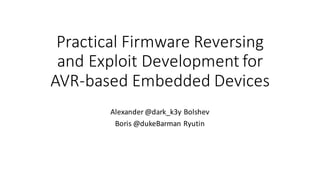
  • 117. Bit  manipulation  instructions sbr r16, 3 ; set bits 0 and 1 in r16 lsl r0 ; r0 << 2 lsr r1 ; r1 >> 2 rol r15 ; cyclic shift r16 bits to the left ror r16 ; cyclic shift r16 bits to the right cbr r18,1 ; clear bit 1 in r18 cbi $16, 1 ; PORTB[1] = 0
  • 118. cd /home/radare/workshop/ex2.2 avr-objcopy –I ihex –O binary blink.hex blink.bin r2 –a avr blink.bin Ex  2.2:  Blink!  RE Questions: 1. Identify  main()  function,  define  and  rename  it 2. Find  the  LED  switching  command 3. What  type  of  delay  is  used  and  why  accuracy  of  MCU  frequency  important? 4. Locate  interrupt  vector  and  init code,  explain  what  happens  inside  init code
  • 119. Reversing:  function  szignatures • Majority  of  firmware  contains  zero  or  little  strings. • How  to  start? • Use  function  signatures. • However,  in  AVR  world  signatures  may  be  to  vary. • Be  prepared  to  guess  target  compiler/library/RTOS  and  options…  or   bruteforceit. • In  R2,  signatures  are  called  zignatures.
  • 121. Embedded  code  priorities • Size • Speed • Hardware  limits • Redundancy • … • … • … • … • Security
  • 122. Fuzzing specifics • Fuzzing  is  a  fuzzing.  Everywhere. • But…  we’re  in embedded  world • Sometimes  you  can detect  crash  through  test/debug  UART  or  pins • In  most  cases,  you  can  detect  crash  only  by  noticing  that  device  is  no   longer  response • Moreover,  watchdog  timer can  limit  your  detection  capabilities  by   resetting  the  device • So  how  to  detect  crash?
  • 123. Fuzzing:  ways  to  detect  crash • JTAG  debugger  – break  on  RESET • External  analysis  of  functionality  – detect  execution  pauses • Detect  bootloader/initialization  code  (e.g.  for  SRAM)  behavior  with   logic  analyzer  and/or  FPGA • Detect  power  consumption  change  with  oscilloscope/DAQ
  • 124. Sometimes  Arduino  is  enough  to  detect   • I2C and  SPI  init sequences  could  be  captured  by  Arduino  GPIOs • In  case  bootloader is  slow  and  has  ~1  second  loading  delay,  this   power  consumption  reduction  could  be reliably  detected  with  cheap   current  sensor,  e.g.:   SparkFun Low Current Sensor Breakout - ACS712 https://www.sparkfun.com/products/8883 +
  • 127. Quick  intro  to  ROP-­‐chains • Return  Oriented  Programming • Series  of  function  returns • We  are  searching  for  primitives  (“gadgets”)  ending  with  ‘ret’  that   could  be  chained  into  a  useful  code  sequence • SP  is  our  new  PC
  • 128. Notice:  Arduino • The  next  examples/exercises  will  be  based  upon  Arduio ‘libc’  (in  fact,   Non-­‐GNU  AVR  libc +  Arduino  wiring  libs) • We’re  using  Arduino  because  it is  sufficiently  complex,  full  of  gadgets   and  free  (vs.  IAR  or  CV  which  are  also  complex  and  full  of  gadgets)   • Also,  Arduino  is  fairly  popular  today  due  to  enormous  number  of   libraries  and  “quick  start”  (and  quick  bugs)
  • 129. cd /home/radare/workshop/ex3.1 avarice --mkI --jtag /dev/ttyUSB0 -p -e --file build- crumbuino128/ex3.1.hex -d :4242 In  the  new  terminal  window: avr-gdb (gdb) target remote :4242 Ex  3.1  – 3.3
  • 130. Example  3.1 Abusing  functionality:  ret  to   function
  • 131. Internal-­‐SRAM  only  memory  map http://www.atmel.com/webdoc/AVRLibcReferenceManual/malloc_1malloc_intro.html Overflowing  the  heap  =>  Rewriting  the  stack!
  • 132. How  to  connect  data(string/binary)  to  code? Standard  model:  with  .data  variables • Determine  data  offset  in  flash • Find  init code/firmware  prologue   where  .data   is  copied  to  SRAM • Using  debugging   or  own  brain  calculate  offset   of  data  in  SRAM • Search  code  for  this  address Economy  model:  direct  read  with   lpm/elpm • Determine  data  offset  in  flash • Search  code  with  *lpm addressing  to  this  offset
  • 133. ABI,  Types  and  frame  layouts  (GCC) • Types:  standard  (short  ==  int ==  2,  long  ==  4,  except  for  double  (4)) • Int could  be  8bit  if  -­‐mint8  option  is  enforced • Call-­‐used:  R18–R27,  R30,  R31 • Call-­‐saved:  R2–R17,  R28,  R29 • R29:R28  used  as  frame  pointer • Frame  layout  after  function  prologue: incoming  arguments return  address saved  registers stack  slots,  Y+1  points  at  the  bottom
  • 134. Calling  convention:  arguments • An  argument  is  passed  either  completely  in  registers  or  completely  in   memory • To  find  the  register  where  a  function  argument  is  passed,  initialize  the   register  number Rn with  R26  and  follow  the  procedure: 1. If  the  argument  size  is  an  odd  number  of  bytes,  round  up  the  size  to  the  next  even  number. 2. Subtract  the  rounded  number  from  the  register  number Rn. 3. If  the  new Rn is  at  least  R18  and  the  size  of  the  object  is  non-­‐zero,  then  the  low-­‐byte  of  the   argument  is  passed  in Rn.  Other  bytes  will  be  passed  in  Rn+1, Rn+2,  etc. 4. If  the  new  register  number Rn is  smaller  than  R18  or  the  size  of  the  argument  is  zero,  the   argument  will  be  passed  in  memory. 5. If  the  current  argument  is  passed  in  memory,  stop  the  procedure:  All  subsequent  arguments   will  also  be  passed  in  memory. 6. If  there  are  arguments  left,  goto 1.  and  proceed  with  the  next  argument. • Varagrs are  passed  on  the  stack  
  • 135. Calling  conventions:  returns • Return  values  of  size  1  byte  up  to  8  bytes  (including)  will  be  returned   in  registers   • For  example,  an  8-­‐bit  value  is  returned  in  R24  and  an  32-­‐bit  value  is   returned  R22...R25 • Return  values  whose  size  is  outside  that  range  will  be  returned  in   memory
  • 136. Example For int func (char a, long b); • a  will  be  passed  in  R24 • b  will  be  passed  in  R20,  R21,  R22  and  R23  with  the  LSB  in  R20  and  the   MSB  in  R23 • The  result  is  returned  in  R24  (LSB)  and  R25  (MSB)
  • 138. ROP  gadget  sources • User  functions • “Standard”  or  RTOS  functions • Data  segment  J • Bootloader section More  code  =>  more  gadgets
  • 139. ROP  chain  size • It is  MCU • SRAM  is  small • SRAM  is  divided  between  register  file,  heap  and  stack • Stack  size  is  small • We are  limited  in  chain  size • Obviously,  you  will  be  constrained  to  20-­‐40  bytes  (~15-­‐30  gadgets) • However  it  all  depends  on  compiler  and  memory  model http://www.atmel.com/webdoc/AVRLibcReferenceManual/malloc_1malloc_tunables.html
  • 140. Memory  maps  – external  SRAM/separated  stack
  • 141. Memory  maps  – external  SRAM/mixed  stack
  • 142. Detecting  “standard”  functions • In  AVR  world  there  are  a  lot  of  different  compilers,  libraries  and  even   RToSes • Thus,  “standard”  function  could  vary • More  bad  news:  memory  model  and  optimization  options  can  change   function • The  best  approach  is  to  try  to  detect  functions  like  malloc/str(n)cpy and  then  find  the  exact  compiler/options  that  generates  this  code • After  that,  use  function  signatures  to  restore  the  rest  of  the  code • In  Radare2,  you  could  use  zignatures or  Yara
  • 144. Exercise  3.1 ret  2  function Build  exploit  that  starts  with  ABC  but  calls  switchgreen()  function
  • 145. Exercise  3.3 Print  something  else 3.3.1  Build  exploit  that  prints  “a  few  seconds…” 3.3.2  (homework)  Build  exploit  that  prints  “blink  a  few  seconds…”
  • 146. cd /home/radare/workshop/ex3.1 • In  Blink.ino change  APNAME  constant  from  “esp_123”  to  “esp_<your3digitnumber>”   make avr-objdump –I ihex –O binary build-crumbuino128/ex3.4.hex ex3.4.bin avarice --mkI --jtag /dev/ttyUSB0 -p -e --file build- crumbuino128/ex3.4.hex -g :4242 avr-gdb • Connect  to  WiFi “esp_<your3digitnumber>”  (password:  1234567890)  and  type  http://192.168.4.1 in  your  browser Ex  3.4
  • 148. Exercise  3.4 UARTing using  HTTP  query
  • 149. Exercise  3.5 Blink  using  HTTP  Post (homework)
  • 150. It is  possible  to  construct  ROP  with  a  debugger… …But  if  you  don’t  have  one,  how  could  you   determine  the  overflow  point? •Reverse  firmware  and  use  an  external  analysis  to  find   function  that  overflows •Bruteforce it!
  • 151. Arduino  blink   (ROP  without  debugger) • Connect  Arduino board  using  MicroUSB cable cd /home/radare/workshop/ex_arduino make upload (click  reset  on  arduino just  before  it) • Run  cutecom and  connect  to  /dev/ttyACM0  using  speed  9600  
  • 152. Arduino  blink   (ROP  without  debugger) Modify  ROP  chain  to  generate  another  blinking  pattern
  • 154. What  do  we  want?  (again) • Evade  watchdog • Work  with  persistent  memory  (EEPROM  and  Flash) • Stay  persistent  in  device • Control  device  over  long  time
  • 155. Evade  the  watchdog In  most  cases,  there  three  ways: 1. Find  a  ROP  with  WDR and  periodically  jump  on  it 2. Find  watchdog  disabling  code  and  try  to  jump  on  it 3. Construct  watchdog  disabling  code  using  watchdog  enabling  code Set  r18  to  0  and  JMP  here
  • 156. Fun  and  scary  things  to  do  with  memory… • Read/write  EEPROM  (and  extract  cryptographic  keys) • Read  parts  of  flash  (e.g.,  read  locked  bootloader section)   - Could  be  more  useful  than  it  seems • Staying  persistent  (writing  flash)
  • 157. Reading  EEPROM/Flash • In  most  cases  it is  easy  to  find  gadget(s)  that  reads  byte  from  EEPROM   or  flash  and  stores  it  somewhere • We  could  send  this  byte  back  over  UART  or  any  external  channel   gadgets • Not  always  possible,  but  there  are  good  chances
  • 158. Writing  flash • Writing  flash  is  locked  during  normal  program  execution • However,  if  you  use  “jump-­‐to-­‐bootloader”  trick,  you  could  write  flash   from  bootloader sections • To  do  this,  you  need  bootloader which  has  enough  gadgets • Modern  bootloaders are  large  and  you  may  be  lucky  quite  often  (e.g.   Arduino  bootloader) • Remember  to  disable  interrupts before  jumping  to  bootloader
  • 159. “Infinite-­‐ROP”  trick* 1. Set  array  to  some  “upper”  stack  address  (A1)  and  N  to  some  value   (128/256/etc)  and  JMP  to  read(..) 2. Output  ROP-­‐chain  from  UART  to  A1.   3. Set  SPH/SPL  to  A1  (gadgets  could  be  got  from  init code) 4. JMP  to  RET. 5. ??? 6. Profit! Don’t  forget  to  include  1  and  3-­‐4  gadgets  in  the  ROP-­‐chain  that  you  are   sending  by  UART. *Possible  on  firmwares with  read(array,  N)  from  UART  functions   and  complex  init code
  • 161. Mitigations  (software) • Safe  coding/Don’t  trust  external  data  (read  24  deadly  sins  of  computer   security) • Reduce  code  size  (less  code  -­‐>  less  ROP  gadgets) • Use  rjmp/jmp instead  of  call/ret (but  it  won’t  save  you  from  ret2   function) • Use “inconvenient”  memory  models  with  small  stack   • Use  stack  canaries  in  your  RTOS • Limit  external  libraries • Use  watchdogs • Periodically  check  stack  limits  (to  avoid  stack  expansion  tricks)
  • 162. Mitigations  (hardware) • Disable  JTAG/debuggers/etc,  remove  pins/wires  of  JTAG/ISP/UART • Write  lock  bits  to  0/0 • Use  multilayered  PCBs • Use  external/hardware  watchdogs • Use  modern  MCUs  (more  secure  against  various  hardware  attacks) • Use  external  safety  controls/processors And  last,  but  not  least: • Beware  of  Dmitry  Nedospasov ;-­‐)
  • 163. Conclusions • RCE  on  embedded  systems  isn’t  so  hard  as  it  seems. • Abuse  of  functionality  is  the  main  consequence  of  such  attacks • However,  more  scary  things  like  extracting  cipherkeys or  rewriting  the   flash  are  possible • When  developing  embedded  system  remember  that  security  also   should  be  part  of  the  software  DLC  process
  • 164. Books/links • Atmega128  disasm thread:  http://www.avrfreaks.net/forum/disassembly-­‐atmega128-­‐bin-­‐file • Exploiting  buffer  overflows  on  arduino:  http://electronics.stackexchange.com/questions/78880/exploiting-­‐ stack-­‐buffer-­‐overflows-­‐on-­‐an-­‐arduino • Code  Injection  Attacks  on  Harvard-­‐Architecture  Devices:  http://arxiv.org/pdf/0901.3482.pdf • Buffer  overflow  attack  on  an  Atmega2560:  http://www.avrfreaks.net/forum/buffer-­‐overflow-­‐attack-­‐ atmega2560?page=all • Jump  to  bootloader:  http://www.avrfreaks.net/forum/jump-­‐bootloader-­‐app-­‐help-­‐needed • AVR  Libc reference  manual:   http://www.atmel.com/webdoc/AVRLibcReferenceManual/overview_1overview_avr-­‐libc.html • AVR  GCC  calling  conventions:  https://gcc.gnu.org/wiki/avr-­‐gcc • Travis  Goodspeed,   Nifty  Tricks  and  Sage  Advice  for  Shellcode on  Embedded  Systems:   https://conference.hitb.org/hitbsecconf2013ams/materials/D1T1%20-­‐%20Travis%20Goodspeed%20-­‐ %20Nifty%20Tricks%20and%20Sage%20Advice%20for%20Shellcode%20on%20Embedded%20Systems.pdf • Pandora’s  Cash  Box:  The  Ghost  Under  Your  POS:  https://recon.cx/2015/slides/recon2015-­‐17-­‐nitay-­‐ artenstein-­‐shift-­‐reduce-­‐Pandora-­‐s-­‐Cash-­‐Box-­‐The-­‐Ghost-­‐Under-­‐Your-­‐POS.pdf
  • 165. Radare2.  Links • http://radare.org • https://github.com/pwntester/cheatsheets/blob/master/radare2. md • https://www.gitbook.com/book/radare/radare2book/details • https://github.com/radare/radare2ida