SlideShare a Scribd company logo
LANDMARK BASED IMAGE
REGISTRATION USING THIN PLATE
SPLINE WITH FEATURE MATCHING
Under the Guidance of
Mr. Soumik Ghosh
Assistant Professor, UIT,Golapbag,Burdwan
Prepared By:
Ranjan Ganguli
ME2014-10014
Master of engineering
Department of Computer Science and Engineering
University Institute of Technology
Golapbag,Burdwan
Objective
• The purpose of this project is to produce
deformation of an input image using set of
landmark points and making a correspondence
between them.
Application: medical image processing, robotics
Review for Thin Plate Spline
• Rigid-body alignment
• Non-rigid deformation
– Intrinsic methods:
deforming the boundary
points
– An optimization problem
• Minimize shape distortion
• Maximize fit, smoothing After
Before
Source
Target
Thin Plate Spline deformation
Technique
Analogues to bending a thin sheet of metal extending to infinity[1]
Thin-Plate Spline
• Given corresponding source and target points
• Computes a deformation function for every
point in the 2D plane.
• Input
– Source points(black): p1,…,pn
– Target points(gray): q1,…,qn
• Output
– A deformation function f[p] for any point p..[2]
Thin-Plate Spline
pi
qi
f[p]
• Distortion or Bending Energy equation:
- Integral of second order partial derivatives
along x and y axis[3].
Thin-Plate Spline
How to Solve this Equation?
Need to solve various matrix equations
• Thus ,the solution to this bending energy equation:
f(x,y) gives the surface heights of mapping all points
in the plane[1].
Thin-Plate Spline
Final deformed or warped image with a set of
landmark points
Thin Plate Spline
Original image Deformed image
Blue dots represent the landmark points
How to match “Feature Points“
between deformed image and original
image?
Matching Feature Points
Technique:
• Developed by David Lowe
• University of British Columbia
• Initial paper ICCV 1999
• Newer journal paper IJCV 2004
SIFT(SCALE INVARIANT FEATURE TRANSFORM)
Overall Procedure at a High Level
1. Scale-space extrema detection
2. Keypoint localization
3. Orientation assignment
4. Keypoint description
Search over multiple scales and image locations.
Fit a model to determine location and scale.
Select key points based on a measure of stability.
Compute best orientation(s) for each key point region.
Use local image gradients at selected scale and rotation
to describe each key point region.
Scale-space extrema detection
• Find the points, whose surrounding patches (with some
scale) are distinctive.
• An approximation to the scale-normalized Laplacian of
Gaussian (LoG)
Maxima and minima in a
3*3*3 neighborhood
Keypoint localization
• There are still a lot of points, some of them are
not good enough.
• The locations of key points may be not accurate.
• Eliminating edge points.
Eliminating edge points
• Such a point has large principal curvature across the
edge but a small one in the perpendicular direction
• The principal curvatures can be calculated from a
Hessian function
• The eigenvalues of H are proportional to the principal
curvatures, so two eigenvalues shouldn’t diff too much
project_PPT_final
Orientation assignment
• Assign an orientation to each keypoint, the keypoint
descriptor can be represented relative to this orientation
and therefore achieve invariance to image rotation
• Compute magnitude and orientation on the Gaussian
smoothed images
Orientation assignment
• A histogram is formed by quantizing the
orientations into 36 bins;
• Peaks in the histogram correspond to the
orientations of the patch;
• For the same scale and location, there could be
multiple keypoints with different orientations;
Feature descriptor
Feature descriptor
• Based on 16*16 patches
• 4*4 subregions
• 8 bins in each subregion
• 4*4*8=128 dimensions in total
project_PPT_final
Feature matching
Conclusion
This paper includes non-rigid based image
registration using Thin Plate Spline with Feature
Matching. Landmark has been selected either
manually through mouse or can be assigned
initially. SIFT helps deformed image illumination,
scale independent and matched with various
other images. Thus this process can widely
applicable to medical imaging , object
identification ,robotics etc where object are at
different positions all the time
Future Scope
• Method
1. Gauss-Newton Method
Advantage:
Easy to converge for small number of points.
2. - Quasi-Newton Method
Advantage:
Does not require calculation of image gradient
How do we get the original image from a
deformed image?
( Optimization)
Idea of Optimization
Pk+1 = Pk + ak.gk.
The value of ‘a’ and ‘g’ has to be calculated
-Gauss-Newton method
-Newton Quasi method
References
[1]F. L. Bookstein, “Principal warps: Thin-plate splines and the decomposition
of deformations,” IEEE Trans. Pattern Anal. Machine. Intell.
[2] Wahba, G. (1979). How to smooth curves and surfaces with splines and
cross-validation. Proc. 24th Conference on the Design of Experiments.
[3] Broomhead, David H.; Lowe, David (1988). "Multivariable Functional
Interpolation and Adaptive Networks" (PDF). Complex Systems.
Thanks!

More Related Content

PDF
Optical modeling and design of freeform surfaces using anisotropic Radial Bas...
PDF
Evaluation of illumination uniformity metrics in design and optimization of ...
PDF
Improved Characters Feature Extraction and Matching Algorithm Based on SIFT
PPT
Surface Data Capture Image Matching
PPTX
IMAGE SEGMENTATION TECHNIQUES
PPT
Image segmentation
PPT
Determination of System Geometrical Parameters and Consistency between Scans ...
PPTX
Morphological image processing
Optical modeling and design of freeform surfaces using anisotropic Radial Bas...
Evaluation of illumination uniformity metrics in design and optimization of ...
Improved Characters Feature Extraction and Matching Algorithm Based on SIFT
Surface Data Capture Image Matching
IMAGE SEGMENTATION TECHNIQUES
Image segmentation
Determination of System Geometrical Parameters and Consistency between Scans ...
Morphological image processing

What's hot (20)

PPTX
PPTX
OpenCV presentation series- part 5
PDF
Radial Fourier Analysis (RFA) Descriptor with Fourier-based Keypoint Orientation
PDF
Algorithmic Techniques for Parametric Model Recovery
PDF
An automatic algorithm for object recognition and detection based on asift ke...
PPTX
Line detection algorithms
PPT
Ajay ppt region segmentation new copy
PDF
DeepStrip: High Resolution Boundary Refinement
PDF
Research Analysis and Design of Geometric Transformations using Affine Geometry
PPT
Self-dependent 3D face rotational alignment using the nose region
PDF
AN IMPLEMENTATION OF ADAPTIVE PROPAGATION-BASED COLOR SAMPLING FOR IMAGE MATT...
PPT
mathpsy2012 poster_Shweta_3(1)
PDF
Feature extraction based retrieval of
PDF
EFFECTIVE INTEREST REGION ESTIMATION MODEL TO REPRESENT CORNERS FOR IMAGE
PPT
Shading
PPT
Registration & Modeling of Shapes with Uncertainties
PPTX
Finding Licence Plates in an Image (Algorithm)
PPTX
3d tracking : chapter4 natural features, model-based tracking
PPT
Cvpr2007 object category recognition p4 - combined segmentation and recogni...
PPTX
Final Presentation
OpenCV presentation series- part 5
Radial Fourier Analysis (RFA) Descriptor with Fourier-based Keypoint Orientation
Algorithmic Techniques for Parametric Model Recovery
An automatic algorithm for object recognition and detection based on asift ke...
Line detection algorithms
Ajay ppt region segmentation new copy
DeepStrip: High Resolution Boundary Refinement
Research Analysis and Design of Geometric Transformations using Affine Geometry
Self-dependent 3D face rotational alignment using the nose region
AN IMPLEMENTATION OF ADAPTIVE PROPAGATION-BASED COLOR SAMPLING FOR IMAGE MATT...
mathpsy2012 poster_Shweta_3(1)
Feature extraction based retrieval of
EFFECTIVE INTEREST REGION ESTIMATION MODEL TO REPRESENT CORNERS FOR IMAGE
Shading
Registration & Modeling of Shapes with Uncertainties
Finding Licence Plates in an Image (Algorithm)
3d tracking : chapter4 natural features, model-based tracking
Cvpr2007 object category recognition p4 - combined segmentation and recogni...
Final Presentation
Ad

Viewers also liked (7)

PPT
Comparing 3-D Interpolation Techniques
PDF
Metodenumerik math10
PDF
B spline
PPTX
3D Graphics : Computer Graphics Fundamentals
PPT
Quadric surfaces
PPT
pattern classification
Comparing 3-D Interpolation Techniques
Metodenumerik math10
B spline
3D Graphics : Computer Graphics Fundamentals
Quadric surfaces
pattern classification
Ad

Similar to project_PPT_final (20)

PDF
Passive stereo vision with deep learning
PPTX
Various object detection and tracking methods
PDF
Lec16: Medical Image Registration (Advanced): Deformable Registration
PPTX
Surface reconstruction using point cloud
PPTX
06 image features
PDF
PPT s07-machine vision-s2
PDF
PPT s06-machine vision-s2
PPTX
Computer Vision UNit 3 Presentaion Slide
PDF
PPT s11-machine vision-s2
PDF
Two marks with answers ME6501 CAD
PDF
Cad ala brep, csg and sweep representation gtu
PDF
5_Geometric_Modeling.pdf
PPTX
Close range Photogrammeetry
PPT
cohenmedioni.ppt
PPT
digital imagesegmentation-191212120951.ppt
PDF
426 Lecture5: AR Registration
PDF
187186134 5-geometric-modeling
PDF
5 geometric-modeling-ppt-university-of-victoria
PDF
187186134 5-geometric-modeling
PDF
5 geometric modeling
Passive stereo vision with deep learning
Various object detection and tracking methods
Lec16: Medical Image Registration (Advanced): Deformable Registration
Surface reconstruction using point cloud
06 image features
PPT s07-machine vision-s2
PPT s06-machine vision-s2
Computer Vision UNit 3 Presentaion Slide
PPT s11-machine vision-s2
Two marks with answers ME6501 CAD
Cad ala brep, csg and sweep representation gtu
5_Geometric_Modeling.pdf
Close range Photogrammeetry
cohenmedioni.ppt
digital imagesegmentation-191212120951.ppt
426 Lecture5: AR Registration
187186134 5-geometric-modeling
5 geometric-modeling-ppt-university-of-victoria
187186134 5-geometric-modeling
5 geometric modeling

project_PPT_final

  • 1. LANDMARK BASED IMAGE REGISTRATION USING THIN PLATE SPLINE WITH FEATURE MATCHING Under the Guidance of Mr. Soumik Ghosh Assistant Professor, UIT,Golapbag,Burdwan Prepared By: Ranjan Ganguli ME2014-10014 Master of engineering Department of Computer Science and Engineering University Institute of Technology Golapbag,Burdwan
  • 2. Objective • The purpose of this project is to produce deformation of an input image using set of landmark points and making a correspondence between them. Application: medical image processing, robotics
  • 3. Review for Thin Plate Spline • Rigid-body alignment • Non-rigid deformation – Intrinsic methods: deforming the boundary points – An optimization problem • Minimize shape distortion • Maximize fit, smoothing After Before Source Target
  • 4. Thin Plate Spline deformation Technique Analogues to bending a thin sheet of metal extending to infinity[1]
  • 5. Thin-Plate Spline • Given corresponding source and target points • Computes a deformation function for every point in the 2D plane.
  • 6. • Input – Source points(black): p1,…,pn – Target points(gray): q1,…,qn • Output – A deformation function f[p] for any point p..[2] Thin-Plate Spline pi qi f[p]
  • 7. • Distortion or Bending Energy equation: - Integral of second order partial derivatives along x and y axis[3]. Thin-Plate Spline
  • 8. How to Solve this Equation?
  • 9. Need to solve various matrix equations
  • 10. • Thus ,the solution to this bending energy equation: f(x,y) gives the surface heights of mapping all points in the plane[1]. Thin-Plate Spline
  • 11. Final deformed or warped image with a set of landmark points Thin Plate Spline Original image Deformed image Blue dots represent the landmark points
  • 12. How to match “Feature Points“ between deformed image and original image?
  • 13. Matching Feature Points Technique: • Developed by David Lowe • University of British Columbia • Initial paper ICCV 1999 • Newer journal paper IJCV 2004 SIFT(SCALE INVARIANT FEATURE TRANSFORM)
  • 14. Overall Procedure at a High Level 1. Scale-space extrema detection 2. Keypoint localization 3. Orientation assignment 4. Keypoint description Search over multiple scales and image locations. Fit a model to determine location and scale. Select key points based on a measure of stability. Compute best orientation(s) for each key point region. Use local image gradients at selected scale and rotation to describe each key point region.
  • 15. Scale-space extrema detection • Find the points, whose surrounding patches (with some scale) are distinctive. • An approximation to the scale-normalized Laplacian of Gaussian (LoG)
  • 16. Maxima and minima in a 3*3*3 neighborhood
  • 17. Keypoint localization • There are still a lot of points, some of them are not good enough. • The locations of key points may be not accurate. • Eliminating edge points.
  • 18. Eliminating edge points • Such a point has large principal curvature across the edge but a small one in the perpendicular direction • The principal curvatures can be calculated from a Hessian function • The eigenvalues of H are proportional to the principal curvatures, so two eigenvalues shouldn’t diff too much
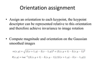
  • 20. Orientation assignment • Assign an orientation to each keypoint, the keypoint descriptor can be represented relative to this orientation and therefore achieve invariance to image rotation • Compute magnitude and orientation on the Gaussian smoothed images
  • 21. Orientation assignment • A histogram is formed by quantizing the orientations into 36 bins; • Peaks in the histogram correspond to the orientations of the patch; • For the same scale and location, there could be multiple keypoints with different orientations;
  • 23. Feature descriptor • Based on 16*16 patches • 4*4 subregions • 8 bins in each subregion • 4*4*8=128 dimensions in total
  • 26. Conclusion This paper includes non-rigid based image registration using Thin Plate Spline with Feature Matching. Landmark has been selected either manually through mouse or can be assigned initially. SIFT helps deformed image illumination, scale independent and matched with various other images. Thus this process can widely applicable to medical imaging , object identification ,robotics etc where object are at different positions all the time
  • 27. Future Scope • Method 1. Gauss-Newton Method Advantage: Easy to converge for small number of points. 2. - Quasi-Newton Method Advantage: Does not require calculation of image gradient How do we get the original image from a deformed image? ( Optimization)
  • 28. Idea of Optimization Pk+1 = Pk + ak.gk. The value of ‘a’ and ‘g’ has to be calculated -Gauss-Newton method -Newton Quasi method
  • 29. References [1]F. L. Bookstein, “Principal warps: Thin-plate splines and the decomposition of deformations,” IEEE Trans. Pattern Anal. Machine. Intell. [2] Wahba, G. (1979). How to smooth curves and surfaces with splines and cross-validation. Proc. 24th Conference on the Design of Experiments. [3] Broomhead, David H.; Lowe, David (1988). "Multivariable Functional Interpolation and Adaptive Networks" (PDF). Complex Systems.