RTC Interfacing and Programming
Download as PPTX, PDF9 likes7,611 views

The document provides an overview of the DS12887 real-time clock (RTC) chip used in embedded systems, detailing its features such as timekeeping, alarms, and interfacing with microcontrollers. It explains the chip's internal architecture, memory allocation, and capabilities for handling time and date information, including leap year calculations. Additionally, it covers programming aspects for alarms and interrupt requests associated with the DS12887, facilitating efficient time management in various applications.


RTC Interfacing and Programming
- 1. 1 The 8051 Microcontroller and Embedded Systems CHAPTER 15 RTC Interfacing and Programming
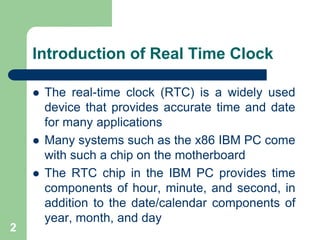
- 2. Introduction of Real Time Clock The real-time clock (RTC) is a widely used device that provides accurate time and date for many applications Many systems such as the x86 IBM PC come with such a chip on the motherboard The RTC chip in the IBM PC provides time components of hour, minute, and second, in addition to the date/calendar components of year, month, and day 2
- 3. Introduction of Real Time Clock The RTC chip uses an internal battery, which keeps the time and date even when the power is off One of the most widely used RTC chips is the DS 12887 from Dallas Semiconductor /Maxim Corp It uses an internal lithium battery to keep operating for over 10 years in the absence of external power 3
- 4. Introduction of Real Time Clock According to the DS 12887 data sheet from Maxim, it keeps track of “seconds, minutes, hours, days, day of week, date, month, and year with leap-year compensation valid up to year 2100″ The above information is provided in both binary (hex) and BCD formats. The DS 12887 supports both 12-hour and 24-hour clock modes with AM and PM in the 12-hour 4 mode
- 5. It also supports the Daylight Savings Time option The DS 12887 uses CMOS technology to keep the power consumption low and it has the designation DS12C887, where C is for CMOS The DS12887 has a total of 128 bytes of nonvolatile RAM 5 Introduction of Real Time Clock
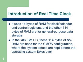
- 6. It uses 14 bytes of RAM for clock/calendar and control registers, and the other 114 bytes of RAM are for general-purpose data storage In the x86 IBM PC, these 114 bytes of NV-RAM are used for the CMOS configuration, where the system setups are kept before the operating system takes over 6 Introduction of Real Time Clock
- 7. Pin Diagram of DS12887 RTC 7
- 8. Address map of the DS12887 8
- 9. The DS12887 has a total of 128 bytes of RAM space with addresses 00 -7FH The first ten locations, 00 – 09, are set aside for RTC values of time, calendar, and alarm data The next four bytes are used for the control and status registers 9 Address map of the DS12887
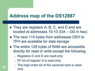
- 10. They are registers A, B, C, and D and are located at addresses 10-13 (OA – OD in hex) The next 114 bytes from addresses OEH to 7FH are available for data storage The entire 128 bytes of RAM are accessible directly for read or write except the following: – Registers C and D are read-only – D7 bit of register A is read-only – The high-order bit of the seconds byte is read-only 10 Address map of the DS12887
- 11. DS12887 Address Location for Time, Calendar, and Alarm 11
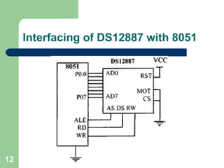
- 12. Interfacing of DS12887 with 8051 12
- 13. Turning on the oscillator for the first time The DS12887 is equipped with the internal oscillator which is turned off in order to save the lithium battery. We need to turn on the oscillator before we use the time keeping features of the DS 12887 To do that, bits D6 – D4 of register A must be set to value 010 13
- 14. Register A Bits for Turning on the DS12887′s Oscillator 14
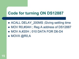
- 15. Code for turning ON DS12887 ACALL DELAY_200MS ;Giving settling time MOV R0,#0AH ; Reg A address of DS12887 MOV A,#20H ; 010 DATA FOR D6-D4 MOVX @R0,A 15
- 16. Bits of Register B 16
- 17. Register C 17 – IRQF =1: if PF = PIE= 1 orAF=AIE= 1 orUF = UIE= 1 – PF Periodic interrupt flag. Periodic interrupts can be generated at a rate of once every 500 ms to once every 122 us. The rate is set by bits RS3 – RSO of register A
- 18. Register C AF Alarm interrupt flag. The AF becomes 1 when the current real time matches the alarm time. AF and AIE of register B together (if both are 1) will allow the IRQ to be asserted low when all the three bytes of the real time (yy:mm:dd) are the same as the bytes in the alarm time The AF also becomes 1 for cases of once per second, once per minute, and once per 18 hour alarm
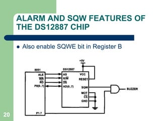
- 19. ALARM AND SQW FEATURES OF THE DS12887 CHIP 19 The SQW pin provides us a square wave output of various frequencies The frequency is chosen by bits RSO – RS3 of register A
- 20. Also enable SQWE bit in Register B 20 ALARM AND SQW FEATURES OF THE DS12887 CHIP
- 21. ALARM FEATURE OF DS12887 CHIP The alarm interrupt can be programmed to occur at rates of – (a) once per day – (b) once per hour – (c) once per minute – (d) once per second 21
- 22. Once-per-day alarm To program the alarm for once per day, we write the desired time for the alarm into the hour, minute, and second RAM locations 1, 3, and 5 As the clock keeps the time, when all three bytes of hour, minute, and second for the real time clock match the values in the alarm hour, minute, and second, the AF (alarm flag) bit in register C of the DS 12887 will go 22 high
- 23. Once-per-hour, minute and second alarms To program the alarm for once per hour, we write value FFH into the alarm hour location of 5 only To program the alarm for once per minute, we write value FFH into both the alarm hour and alarm minute locations of 5 and 3 To program the alarm for once per second, we write value FFH into all three locations of alarm hour, alarm minute, and alarm second 23
- 24. We can poll the AF bit in register C, which is a waste of microcontroller resources, or allow the IRQ pin to be activated upon matching the alarm time with the real time It must be noted that in order to use the IRQ pin of the DS 12887 for an alarm, the interrupt-enable bit for alarm in register B (AIE) must be set high 24 IRQ FEATURE OF THE DS12887 CHIP
- 25. IRQ FEATURE OF THE DS12887 CHIP 25
- 26. Interrupt request (IRQ) is an output pin for the DS12887 RTC chip There are three possible sources that can activate the IRQ pin – (a) alarm interrupt – (b) periodic pulse interrupt – (c) update interrupt We can choose which source to activate the IRQ pin using the interrupt-enable bit in register B of the DS 12887 26 IRQ FEATURE OF THE DS12887 CHIP
- 27. PERIODIC INTERRUPT The second source of interrupt is the periodic interrupt flag (PF) The periodic interrupt flag is part of register C It will go high at a rate set by the RS3 -RSO bits of register A This rate can be from once every 500 ms to once every 122 us as shown The PF becomes 1 when an edge is detected 27 for the period
- 28. Just like alarm interrupt, the periodic interrupt can also be directed to the IRQ pin To use IRQ, the interrupt-enable bits of PIE in register B must be set to 1 In other words, we can poll the PF bit of register C, which is a waste of the microcontroller’s resources, or it can be directed to the hardware IRQ pin If we set PIE = 1, the IRQ pin is asserted low when PF goes high 28 PERIODIC INTERRUPT
- 29. While the alarm interrupt gave us the options from once per day to once per second, the periodic interrupt gives us the option of subsecond interrupts For example, we can write a program to send a message to the screen twice per second (2 Hz) 29 PERIODIC INTERRUPT
- 30. Internal Architecture of DS12887 30