SlideShare a Scribd company logo
Lecture #4
Analytical and Numerical Methods
of Structural Analysis
FLOWCHART OF STRUCTURAL ANALYSIS
2
Real object
Structural
layout
Design model
Only load-carrying structure
is kept
Assumptions and simplifications
are applied, loads are calculated
according to the problem
Results of
analysis
Implementation
on real object
This step is beyond the scope
of structural analysis
Structural analysis
FLOWCHART OF STRUCTURAL ANALYSIS
3
Real object
Structural
layout
Design model
Results of
analysis
Implementation
on real object
FLOWCHART OF STRUCTURAL ANALYSIS
4
Real object
Structural
layout
Design model
Results of
analysis
Implementation
on real object
FLOWCHART OF STRUCTURAL ANALYSIS
5
Real object
Structural
layout
Design model
Results of
analysis
Implementation
on real object
Depending on the kind of
problem which is solved, the
design model could be either as
detailed as structural layout, or
as generalized as below:
METHODS OF STRUCTURAL ANALYSIS
Analytical methods Numerical methods
Best for designing
calculations, suit for
checking calculations with
certain limitations
Best for checking
calculations, practically
effete for designing
calculations
Solutions exist for partial
cases (specific objects)
Versatile and flexible
Need much work to be
developed, but only
simple software for
application
Need expensive and
complex software and
hardware
6
ANALYTICAL METHODS OF STRUCTURAL ANALYSIS
7
Widely used nowadays:
• methods of Mechanics of Materials;
• methods for statically indeterminate structures:
• method of forces;
• method of displacements;
• beam theory for thin-walled structures;
• method of reduction coefficients.
Rarely used nowadays (mostly due to the progress
of numerical methods):
• methods based on Calculus of Variations;
• methods of Theory of Elasticity.
EXAMPLE TO COMPARE ANALYTICAL AND
NUMERICAL METHODS
8
Aim:
Design the steel
bracket to minimize
the self-weight
displacement of the
load.
Given data:
D2=80 mm;
L2=500 mm;
L1=200 mm;
mload=0.5 kg.
Objectives:
D1, δ1, δ2.
load
L1, D1, δ1
L2, D2, δ2
base
BASIC EQUATIONS OF SOLID MECHANICS
9
Equilibrium
equations
Constitutive
equations
Compatibility
equations
This is not only the sum of
forces or moments, but applies
for elementary volume as well
Physical law, expresses
the relation between
stress and strain
Solid body should
remain continuous
while being deformed
BASIC EQUATIONS OF SOLID MECHANICS
10
Equilibrium
equations
Constitutive
equations
Compatibility
equations
This is not only the sum of forces
or moments, but applies for
elementary volume as well.
0
0
0
xyx xz
xy y yz
yzxz z
X ,
x y z
Y ,
x y z
Z ,
x y z
where X ,Y ,Z external forces.
τσ τ
τ σ τ
ττ σ
∂∂ ∂
+ + + =
∂ ∂ ∂
∂ ∂ ∂
+ + + =
∂ ∂ ∂
∂∂ ∂
+ + + =
∂ ∂ ∂
−
BASIC EQUATIONS OF SOLID MECHANICS
11
Equilibrium
equations
Constitutive
equations
Compatibility
equations
Physical law, expresses the
relation between stress and strain.
( )( )
( )( )
( )( )
1
1
1
x x y z
y y x z
z z x y
xy yzxz
xy xz yz
,
E
,
E
,
E
, ,
G G G
ε σ ν σ σ
ε σ ν σ σ
ε σ ν σ σ
τ ττ
γ γ γ
= − +
= − +
= − +
= = =
BASIC EQUATIONS OF SOLID MECHANICS
12
Equilibrium
equations
Constitutive
equations
Compatibility
equations
Solid body should remain
continuous while being deformed.
2 22 2 22
2 2 2 2
2 22
2 2
2
2
2
2
2
2
y xyx x xzz
y yzz
yz xyxz x
yz xy yxz
yz xyxz z
, ,
y x x y z x x z
,
z y y z
,
x x y z y z
,
y x y z x z
.
z x y z x y
ε γε ε γε
ε γε
γ γγ ε
γ γ εγ
γ γγ ε
∂ ∂∂ ∂ ∂∂
+ = + =
∂ ∂ ∂ ∂ ∂ ∂ ∂ ∂
∂ ∂∂
+ =
∂ ∂ ∂ ∂
∂ ∂ ∂ ∂∂
− + + = 
∂ ∂ ∂ ∂ ∂ ∂ 
∂ ∂ ∂ ∂∂
− + = 
∂ ∂ ∂ ∂ ∂ ∂ 
∂ ∂ ∂ ∂∂
+ − = 
∂ ∂ ∂ ∂ ∂ ∂ 
BASIC EQUATIONS OF SOLID MECHANICS
13
Equilibrium
equations
Constitutive
equations
Compatibility
equations
Boundary
conditions:
• geometrical
features;
• supports and
other means of
fixation;
• applied
displacements
and forces.
Design
model
From analytical point of view, every design model can
be expressed as a set of three basic equations with
corresponding boundary conditions.
WAYS TO SOLVE A SOLID MECHANICS PROBLEM
14
Displacements
are set as
unknowns
Strains are
derived
Stresses are
derived
Compatibility
equations
Constitutive
equations
Equilibrium
equations are
solved
Equilibrium
equations
Stresses are
set as
unknowns
Strains are
derived
Constitutive
equations
Equilibrium
equations
Compatibility
equations are
solved
Compatibility
equations
EXAMPLE TO COMPARE ANALYTICAL AND
NUMERICAL METHODS
15
Analytical methods
used:
• Methods of
Mechanics of
Materials;
• Mohr’s integral to
calculate
displacements.
Software used:
MathCAD V14.0
load
L1, D1, δ1
L2, D2, δ2
base
EXAMPLE TO COMPARE ANALYTICAL AND NUMERICAL METHODS
16
EXAMPLE TO COMPARE ANALYTICAL AND NUMERICAL METHODS
17
EXAMPLE TO COMPARE ANALYTICAL AND NUMERICAL METHODS
18
EXAMPLE TO COMPARE ANALYTICAL AND NUMERICAL METHODS
19
EXAMPLE TO COMPARE ANALYTICAL AND NUMERICAL METHODS
20
EXAMPLE TO COMPARE ANALYTICAL AND NUMERICAL METHODS
21
EXAMPLE TO COMPARE ANALYTICAL AND NUMERICAL METHODS
22
EXAMPLE TO COMPARE ANALYTICAL AND NUMERICAL METHODS
23
EXAMPLE TO COMPARE ANALYTICAL AND NUMERICAL METHODS
24
EXAMPLE TO COMPARE ANALYTICAL AND NUMERICAL METHODS
25
METHODS OF STRUCTURAL ANALYSIS
Analytical methods Numerical methods
Best for designing
calculations, suit for
checking calculations with
certain limitations
Best for checking
calculations, practically
effete for designing
calculations
Solutions exist for partial
cases (specific objects)
Versatile and flexible
Need much work to be
developed, but only
simple software for
application
Need expensive and
complex software and
hardware
26
NUMERICAL METHODS OF STRUCTURAL ANALYSIS
27
Most widely used nowadays is
Finite Element Method (FEM).
The structural analysis using FEM is called finite
element analysis (FEA).
Generally, FEM is just a method to solve
differential equations.
The physical background of FEM is the same as in
analytical methods.
FINITE ELEMENT METHOD
28
The smooth field of stresses is calculated using the combination
of basic functions, which are constructed on a mesh.
FINITE ELEMENT METHOD
29
Software work on principle GIGO: “garbage in – garbage out”…
FINITE ELEMENT METHOD
30
Software work on principle GIGO: “garbage in – garbage out”…
FINITE ELEMENT METHOD
31
Software work on principle GIGO: “garbage in – garbage out”…
FINITE ELEMENT METHOD
32
Even if the result is realistic,
you should always check it.
It’s not a big problem
to create a “nice picture” using FEA.
The problem is to get the reliable and verified result.
That’s a difference between professional and
beginner.
FEA is a way to find a stress state,
but not the way to design or to check the strength!
EXAMPLE TO COMPARE ANALYTICAL AND NUMERICAL METHODS
33load
base
Object FEM model
EXAMPLE TO COMPARE ANALYTICAL AND NUMERICAL METHODS
34
Assignment
of parameters
EXAMPLE TO COMPARE ANALYTICAL AND NUMERICAL METHODS
35
Deformed
shape
35 finite elements
in model
EXAMPLE TO COMPARE ANALYTICAL AND NUMERICAL METHODS
36
Optimization
took 7
minutes on
average
office PC.
990 points
were studied.
Analytical method Finite element analysis
Displacement is 7.66 µm
(or 8.07 µm in FEA)
Displacement is 7.81 µm
(or 8.22 µm in FEA)
D1=67 µm, δ1=2 µm,
δ2= 11.23 mm
D1=58 µm, δ1=2 µm,
δ2= 13 mm
Need only simple
software for application
Need expensive and
complex software
37
EXAMPLE TO COMPARE ANALYTICAL AND NUMERICAL METHODS
METHODS OF STRUCTURAL ANALYSIS
Analytical methods Numerical methods
Best for designing
calculations, suit for
checking calculations with
certain limitations
Best for checking
calculations, practically
effete for designing
calculations
Solutions exist for partial
cases (specific objects)
Versatile and flexible
Need much work to be
developed, but only
simple software for
application
Need expensive and
complex software and
hardware
38
EXAMPLE ILLUSTRATING THE DESIGN OF FINITE ELEMENT MODEL
39
Shell model.
12K elements in
model, around 5
minutes to solve
on poor office PC
EXAMPLE ILLUSTRATING THE DESIGN OF FINITE ELEMENT MODEL
40
Solid model.
250K elements, around 20
minutes to solve on powerful PC
(4x4.2GHz processor,
16 GB memory).
EXAMPLE ILLUSTRATING THE DESIGN OF FINITE ELEMENT MODEL
41
Difference?
Certain there is a difference, but for some results it is negligible.
Thus, the model should be built according to problem,
as in analytical methods
FINITE ELEMENT SOFTWARE
42
Widely used nowadays:
• ANSYS;
• Patran/Nastran;
• ABAQUS;
• Solidworks Simulation (former COSMOS);
And many-many others, freeware and proprietary…
Any difference? Generally, no difference. FEA
packages are often customized to be more convenient
for some specific problems. But for most cases,
differences between packages and limitations have
marketing but not the technical reason.
1940
Theoretical aspects were developed for the
first time
1950,
1960
Theoretical background was developed, the
rise of computer power allowed to make first
specific software
1970
Large general-purpose packages appeared
(ANSYS, NASTRAN)
1980 Graphical pre- and post-processing
1990
Rise of the role of automatic meshing, and
thus the model scale
2000 Multi-disciplinary and large-scale problems
43
FINITE ELEMENT METHOD HISTORICAL PROGRESS
PRINCIPAL COMPONENTS OF FEA SOTWARE
44
Pre-processor
Solver
Post-precessor
Construction of the model, setting
the properties, loads, constraints
etc.
Solution itself. Two main types of
solvers are iterative or sparse .
Looking on results, processing of
results, generating “nice figures”
45
FINITE ELEMENT METHOD – OLD INTERFACE
46
FINITE ELEMENT METHOD – MODERN INTERFACE
CONCLUSIONS
• “Analytical method” does not mean “by hand” or “on
paper”, modern software can give large benefits.
• Numerical methods are very exacting in terms of
software and hardware.
• FEA is not a magic key that opens every door. It’s
just a versatile and effective tool to calculate stresses.
• Deep insight is required for successful structural
analysis, no matter is it analytics of FEA.
• Generally, analytical methods are good for
designing, FEA – for checking. However, in many
cases both of methods can be used for both phases of
analysis. 47
CONCLUSIONS
What does it mean to be a professional in structural
analysis?
Knowledge of complex formulas? Usage of modern
software?
Neither of it is an answer. Answer is a deep
understanding of how the structure works, and
application of proper methods according to the given
problem.
Analytical and numerical methods loss their
disadvantages when they are combined together.
48
WHERE TO FIND MORE INFORMATION?
BOOKS AND USEFUL LINKS
49
Good book about structural analysis and Ansys is
E. Madenci, I.Guven. The Finite Element Method and Applications in
Engineering Using ANSYS, 2006
Very useful links are:
Official website resource library ansys.com
Resourse for Ansys users ansys.net
Perfect forum (not for beginners, though) xansys.org
Youtube (it’s not a joke, search “Ansys” for amazing training
videos) youtube.com
… Internet is boundless …
TOPIC OF THE NEXT LECTURE
50
Statically determinate trusses
All materials of our course are available
at department website k102.khai.edu
1. Go to the page “Библиотека”
2. Press “Structural Mechanics (lecturer Vakulenko S.V.)”

More Related Content

PPT
Structural analysis 2
PPSX
Geotechnical Engineering-II [Lec #7: Soil Stresses due to External Load]
PDF
Chapter 06
DOCX
STRENGTH OF MATERIALS 2 MARKS (CE6306/CE8395)
PDF
Lecture 2 bearing capacity
PPTX
STRAIN ENERGY CONCEPT STRENGTH OF MATERIAL
PDF
Chapter 1: Foundation Engineering
PPT
Complex stresses
Structural analysis 2
Geotechnical Engineering-II [Lec #7: Soil Stresses due to External Load]
Chapter 06
STRENGTH OF MATERIALS 2 MARKS (CE6306/CE8395)
Lecture 2 bearing capacity
STRAIN ENERGY CONCEPT STRENGTH OF MATERIAL
Chapter 1: Foundation Engineering
Complex stresses

What's hot (20)

PPTX
PDF
Laterally Loaded Piles
PPT
Shear Force And Bending Moment Diagram For Beam And Frame
PPSX
Geotechnical Engineering-II [Lec #19: General Bearing Capacity Equation]
PDF
Lec04 Earthquake Force Using Response Specturum Method (2) (Earthquake Engine...
PDF
Unit 6- Plate Bending Theory.pdf
PPTX
Chapter 11: Stability of Equilibrium: Columns
PDF
Ch 1 structural analysis stiffness method
PPTX
Principle Of Transmissibility | Mechanical Engineering
PDF
Strength of materials
PPSX
Geotechnical Engineering-II [Lec #8: Boussinesq Method - Rectangular Areas]
PPT
Prof.N.B.HUI Lecture of solid mechanics
PPTX
Lami's Theorem | Mechanical Engineering
PDF
Chapter 3 2
PPTX
Critical State Model (Advance Soil Mechanics)
PDF
PPT
Shear Force and Bending Moment Diagram
PPTX
Types of beams
DOCX
Analysis and Design of Plate Girder Bridges_.docx
PDF
Methods to Determine the Immediate or Elastic Settlement (الهبوط الفورى)
Laterally Loaded Piles
Shear Force And Bending Moment Diagram For Beam And Frame
Geotechnical Engineering-II [Lec #19: General Bearing Capacity Equation]
Lec04 Earthquake Force Using Response Specturum Method (2) (Earthquake Engine...
Unit 6- Plate Bending Theory.pdf
Chapter 11: Stability of Equilibrium: Columns
Ch 1 structural analysis stiffness method
Principle Of Transmissibility | Mechanical Engineering
Strength of materials
Geotechnical Engineering-II [Lec #8: Boussinesq Method - Rectangular Areas]
Prof.N.B.HUI Lecture of solid mechanics
Lami's Theorem | Mechanical Engineering
Chapter 3 2
Critical State Model (Advance Soil Mechanics)
Shear Force and Bending Moment Diagram
Types of beams
Analysis and Design of Plate Girder Bridges_.docx
Methods to Determine the Immediate or Elastic Settlement (الهبوط الفورى)
Ad

Viewers also liked (15)

PDF
Introduction to Discrete-Event Simulation Using SimPy
PPT
Alopecia
PPT
Alopecia
PPTX
Histopathology of alopecia
PPTX
Androgenetic alopecia
PPTX
Female hair loss
PPTX
Alopecia - scaring & non-scaring type.
PPTX
PPT
Alopecia
PDF
Alopecia presentacion
PPT
spread of oral infections
PDF
Introduction to Numerical Analysis
PPTX
Application of Numerical method in Real Life
PPT
Applications of numerical methods
Introduction to Discrete-Event Simulation Using SimPy
Alopecia
Alopecia
Histopathology of alopecia
Androgenetic alopecia
Female hair loss
Alopecia - scaring & non-scaring type.
Alopecia
Alopecia presentacion
spread of oral infections
Introduction to Numerical Analysis
Application of Numerical method in Real Life
Applications of numerical methods
Ad

Similar to S6 l04 analytical and numerical methods of structural analysis (20)

PDF
Operations Research Digital Material.pdf
PDF
Operation research history and overview application limitation
PPTX
Unit 1 - Optimization methods.pptx
PPT
Cs854 lecturenotes01
PPT
Visual Techniques
PPT
Accelerated life testing
PDF
Classification of optimization Techniques
PDF
AOFW CHG433_Part I_wip_Nov2023.pdf presentation
PPTX
COMPUTER AIDED ENGINEERING - INTRODUCTION
PDF
CompEng - Lec01 - Introduction To Optimum Design.pdf
PDF
Surrogate modeling for industrial design
PPTX
Robust Design And Variation Reduction Using DiscoverSim
PDF
LNCS 5050 - Bilevel Optimization and Machine Learning
PPTX
UNIT-2 Quantitaitive Anlaysis for Mgt Decisions.pptx
PPT
PDF
Top 50+ Data Science Interview Questions and Answers for 2025 (1).pdf
PPT
lecture.ppt
PPTX
3. 2. decision making
PDF
Day 1 - Part 1 Introduction to FEA CAE.pdf
Operations Research Digital Material.pdf
Operation research history and overview application limitation
Unit 1 - Optimization methods.pptx
Cs854 lecturenotes01
Visual Techniques
Accelerated life testing
Classification of optimization Techniques
AOFW CHG433_Part I_wip_Nov2023.pdf presentation
COMPUTER AIDED ENGINEERING - INTRODUCTION
CompEng - Lec01 - Introduction To Optimum Design.pdf
Surrogate modeling for industrial design
Robust Design And Variation Reduction Using DiscoverSim
LNCS 5050 - Bilevel Optimization and Machine Learning
UNIT-2 Quantitaitive Anlaysis for Mgt Decisions.pptx
Top 50+ Data Science Interview Questions and Answers for 2025 (1).pdf
lecture.ppt
3. 2. decision making
Day 1 - Part 1 Introduction to FEA CAE.pdf

Recently uploaded (20)

PDF
Well-logging-methods_new................
PPTX
IOT PPTs Week 10 Lecture Material.pptx of NPTEL Smart Cities contd
PPTX
bas. eng. economics group 4 presentation 1.pptx
PPTX
UNIT-1 - COAL BASED THERMAL POWER PLANTS
PPTX
Strings in CPP - Strings in C++ are sequences of characters used to store and...
PDF
The CXO Playbook 2025 – Future-Ready Strategies for C-Suite Leaders Cerebrai...
PPTX
CH1 Production IntroductoryConcepts.pptx
PPTX
Lesson 3_Tessellation.pptx finite Mathematics
PPTX
CYBER-CRIMES AND SECURITY A guide to understanding
PDF
Mohammad Mahdi Farshadian CV - Prospective PhD Student 2026
DOCX
573137875-Attendance-Management-System-original
PPTX
M Tech Sem 1 Civil Engineering Environmental Sciences.pptx
PPTX
Recipes for Real Time Voice AI WebRTC, SLMs and Open Source Software.pptx
DOCX
ASol_English-Language-Literature-Set-1-27-02-2023-converted.docx
PDF
Digital Logic Computer Design lecture notes
PPTX
MCN 401 KTU-2019-PPE KITS-MODULE 2.pptx
PDF
Evaluating the Democratization of the Turkish Armed Forces from a Normative P...
PDF
composite construction of structures.pdf
PPT
Mechanical Engineering MATERIALS Selection
PPTX
OOP with Java - Java Introduction (Basics)
Well-logging-methods_new................
IOT PPTs Week 10 Lecture Material.pptx of NPTEL Smart Cities contd
bas. eng. economics group 4 presentation 1.pptx
UNIT-1 - COAL BASED THERMAL POWER PLANTS
Strings in CPP - Strings in C++ are sequences of characters used to store and...
The CXO Playbook 2025 – Future-Ready Strategies for C-Suite Leaders Cerebrai...
CH1 Production IntroductoryConcepts.pptx
Lesson 3_Tessellation.pptx finite Mathematics
CYBER-CRIMES AND SECURITY A guide to understanding
Mohammad Mahdi Farshadian CV - Prospective PhD Student 2026
573137875-Attendance-Management-System-original
M Tech Sem 1 Civil Engineering Environmental Sciences.pptx
Recipes for Real Time Voice AI WebRTC, SLMs and Open Source Software.pptx
ASol_English-Language-Literature-Set-1-27-02-2023-converted.docx
Digital Logic Computer Design lecture notes
MCN 401 KTU-2019-PPE KITS-MODULE 2.pptx
Evaluating the Democratization of the Turkish Armed Forces from a Normative P...
composite construction of structures.pdf
Mechanical Engineering MATERIALS Selection
OOP with Java - Java Introduction (Basics)

S6 l04 analytical and numerical methods of structural analysis

  • 1. Lecture #4 Analytical and Numerical Methods of Structural Analysis
  • 2. FLOWCHART OF STRUCTURAL ANALYSIS 2 Real object Structural layout Design model Only load-carrying structure is kept Assumptions and simplifications are applied, loads are calculated according to the problem Results of analysis Implementation on real object This step is beyond the scope of structural analysis Structural analysis
  • 3. FLOWCHART OF STRUCTURAL ANALYSIS 3 Real object Structural layout Design model Results of analysis Implementation on real object
  • 4. FLOWCHART OF STRUCTURAL ANALYSIS 4 Real object Structural layout Design model Results of analysis Implementation on real object
  • 5. FLOWCHART OF STRUCTURAL ANALYSIS 5 Real object Structural layout Design model Results of analysis Implementation on real object Depending on the kind of problem which is solved, the design model could be either as detailed as structural layout, or as generalized as below:
  • 6. METHODS OF STRUCTURAL ANALYSIS Analytical methods Numerical methods Best for designing calculations, suit for checking calculations with certain limitations Best for checking calculations, practically effete for designing calculations Solutions exist for partial cases (specific objects) Versatile and flexible Need much work to be developed, but only simple software for application Need expensive and complex software and hardware 6
  • 7. ANALYTICAL METHODS OF STRUCTURAL ANALYSIS 7 Widely used nowadays: • methods of Mechanics of Materials; • methods for statically indeterminate structures: • method of forces; • method of displacements; • beam theory for thin-walled structures; • method of reduction coefficients. Rarely used nowadays (mostly due to the progress of numerical methods): • methods based on Calculus of Variations; • methods of Theory of Elasticity.
  • 8. EXAMPLE TO COMPARE ANALYTICAL AND NUMERICAL METHODS 8 Aim: Design the steel bracket to minimize the self-weight displacement of the load. Given data: D2=80 mm; L2=500 mm; L1=200 mm; mload=0.5 kg. Objectives: D1, δ1, δ2. load L1, D1, δ1 L2, D2, δ2 base
  • 9. BASIC EQUATIONS OF SOLID MECHANICS 9 Equilibrium equations Constitutive equations Compatibility equations This is not only the sum of forces or moments, but applies for elementary volume as well Physical law, expresses the relation between stress and strain Solid body should remain continuous while being deformed
  • 10. BASIC EQUATIONS OF SOLID MECHANICS 10 Equilibrium equations Constitutive equations Compatibility equations This is not only the sum of forces or moments, but applies for elementary volume as well. 0 0 0 xyx xz xy y yz yzxz z X , x y z Y , x y z Z , x y z where X ,Y ,Z external forces. τσ τ τ σ τ ττ σ ∂∂ ∂ + + + = ∂ ∂ ∂ ∂ ∂ ∂ + + + = ∂ ∂ ∂ ∂∂ ∂ + + + = ∂ ∂ ∂ −
  • 11. BASIC EQUATIONS OF SOLID MECHANICS 11 Equilibrium equations Constitutive equations Compatibility equations Physical law, expresses the relation between stress and strain. ( )( ) ( )( ) ( )( ) 1 1 1 x x y z y y x z z z x y xy yzxz xy xz yz , E , E , E , , G G G ε σ ν σ σ ε σ ν σ σ ε σ ν σ σ τ ττ γ γ γ = − + = − + = − + = = =
  • 12. BASIC EQUATIONS OF SOLID MECHANICS 12 Equilibrium equations Constitutive equations Compatibility equations Solid body should remain continuous while being deformed. 2 22 2 22 2 2 2 2 2 22 2 2 2 2 2 2 2 2 y xyx x xzz y yzz yz xyxz x yz xy yxz yz xyxz z , , y x x y z x x z , z y y z , x x y z y z , y x y z x z . z x y z x y ε γε ε γε ε γε γ γγ ε γ γ εγ γ γγ ε ∂ ∂∂ ∂ ∂∂ + = + = ∂ ∂ ∂ ∂ ∂ ∂ ∂ ∂ ∂ ∂∂ + = ∂ ∂ ∂ ∂ ∂ ∂ ∂ ∂∂ − + + =  ∂ ∂ ∂ ∂ ∂ ∂  ∂ ∂ ∂ ∂∂ − + =  ∂ ∂ ∂ ∂ ∂ ∂  ∂ ∂ ∂ ∂∂ + − =  ∂ ∂ ∂ ∂ ∂ ∂ 
  • 13. BASIC EQUATIONS OF SOLID MECHANICS 13 Equilibrium equations Constitutive equations Compatibility equations Boundary conditions: • geometrical features; • supports and other means of fixation; • applied displacements and forces. Design model From analytical point of view, every design model can be expressed as a set of three basic equations with corresponding boundary conditions.
  • 14. WAYS TO SOLVE A SOLID MECHANICS PROBLEM 14 Displacements are set as unknowns Strains are derived Stresses are derived Compatibility equations Constitutive equations Equilibrium equations are solved Equilibrium equations Stresses are set as unknowns Strains are derived Constitutive equations Equilibrium equations Compatibility equations are solved Compatibility equations
  • 15. EXAMPLE TO COMPARE ANALYTICAL AND NUMERICAL METHODS 15 Analytical methods used: • Methods of Mechanics of Materials; • Mohr’s integral to calculate displacements. Software used: MathCAD V14.0 load L1, D1, δ1 L2, D2, δ2 base
  • 16. EXAMPLE TO COMPARE ANALYTICAL AND NUMERICAL METHODS 16
  • 17. EXAMPLE TO COMPARE ANALYTICAL AND NUMERICAL METHODS 17
  • 18. EXAMPLE TO COMPARE ANALYTICAL AND NUMERICAL METHODS 18
  • 19. EXAMPLE TO COMPARE ANALYTICAL AND NUMERICAL METHODS 19
  • 20. EXAMPLE TO COMPARE ANALYTICAL AND NUMERICAL METHODS 20
  • 21. EXAMPLE TO COMPARE ANALYTICAL AND NUMERICAL METHODS 21
  • 22. EXAMPLE TO COMPARE ANALYTICAL AND NUMERICAL METHODS 22
  • 23. EXAMPLE TO COMPARE ANALYTICAL AND NUMERICAL METHODS 23
  • 24. EXAMPLE TO COMPARE ANALYTICAL AND NUMERICAL METHODS 24
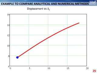
  • 25. EXAMPLE TO COMPARE ANALYTICAL AND NUMERICAL METHODS 25
  • 26. METHODS OF STRUCTURAL ANALYSIS Analytical methods Numerical methods Best for designing calculations, suit for checking calculations with certain limitations Best for checking calculations, practically effete for designing calculations Solutions exist for partial cases (specific objects) Versatile and flexible Need much work to be developed, but only simple software for application Need expensive and complex software and hardware 26
  • 27. NUMERICAL METHODS OF STRUCTURAL ANALYSIS 27 Most widely used nowadays is Finite Element Method (FEM). The structural analysis using FEM is called finite element analysis (FEA). Generally, FEM is just a method to solve differential equations. The physical background of FEM is the same as in analytical methods.
  • 28. FINITE ELEMENT METHOD 28 The smooth field of stresses is calculated using the combination of basic functions, which are constructed on a mesh.
  • 29. FINITE ELEMENT METHOD 29 Software work on principle GIGO: “garbage in – garbage out”…
  • 30. FINITE ELEMENT METHOD 30 Software work on principle GIGO: “garbage in – garbage out”…
  • 31. FINITE ELEMENT METHOD 31 Software work on principle GIGO: “garbage in – garbage out”…
  • 32. FINITE ELEMENT METHOD 32 Even if the result is realistic, you should always check it. It’s not a big problem to create a “nice picture” using FEA. The problem is to get the reliable and verified result. That’s a difference between professional and beginner. FEA is a way to find a stress state, but not the way to design or to check the strength!
  • 33. EXAMPLE TO COMPARE ANALYTICAL AND NUMERICAL METHODS 33load base Object FEM model
  • 34. EXAMPLE TO COMPARE ANALYTICAL AND NUMERICAL METHODS 34 Assignment of parameters
  • 35. EXAMPLE TO COMPARE ANALYTICAL AND NUMERICAL METHODS 35 Deformed shape 35 finite elements in model
  • 36. EXAMPLE TO COMPARE ANALYTICAL AND NUMERICAL METHODS 36 Optimization took 7 minutes on average office PC. 990 points were studied.
  • 37. Analytical method Finite element analysis Displacement is 7.66 µm (or 8.07 µm in FEA) Displacement is 7.81 µm (or 8.22 µm in FEA) D1=67 µm, δ1=2 µm, δ2= 11.23 mm D1=58 µm, δ1=2 µm, δ2= 13 mm Need only simple software for application Need expensive and complex software 37 EXAMPLE TO COMPARE ANALYTICAL AND NUMERICAL METHODS
  • 38. METHODS OF STRUCTURAL ANALYSIS Analytical methods Numerical methods Best for designing calculations, suit for checking calculations with certain limitations Best for checking calculations, practically effete for designing calculations Solutions exist for partial cases (specific objects) Versatile and flexible Need much work to be developed, but only simple software for application Need expensive and complex software and hardware 38
  • 39. EXAMPLE ILLUSTRATING THE DESIGN OF FINITE ELEMENT MODEL 39 Shell model. 12K elements in model, around 5 minutes to solve on poor office PC
  • 40. EXAMPLE ILLUSTRATING THE DESIGN OF FINITE ELEMENT MODEL 40 Solid model. 250K elements, around 20 minutes to solve on powerful PC (4x4.2GHz processor, 16 GB memory).
  • 41. EXAMPLE ILLUSTRATING THE DESIGN OF FINITE ELEMENT MODEL 41 Difference? Certain there is a difference, but for some results it is negligible. Thus, the model should be built according to problem, as in analytical methods
  • 42. FINITE ELEMENT SOFTWARE 42 Widely used nowadays: • ANSYS; • Patran/Nastran; • ABAQUS; • Solidworks Simulation (former COSMOS); And many-many others, freeware and proprietary… Any difference? Generally, no difference. FEA packages are often customized to be more convenient for some specific problems. But for most cases, differences between packages and limitations have marketing but not the technical reason.
  • 43. 1940 Theoretical aspects were developed for the first time 1950, 1960 Theoretical background was developed, the rise of computer power allowed to make first specific software 1970 Large general-purpose packages appeared (ANSYS, NASTRAN) 1980 Graphical pre- and post-processing 1990 Rise of the role of automatic meshing, and thus the model scale 2000 Multi-disciplinary and large-scale problems 43 FINITE ELEMENT METHOD HISTORICAL PROGRESS
  • 44. PRINCIPAL COMPONENTS OF FEA SOTWARE 44 Pre-processor Solver Post-precessor Construction of the model, setting the properties, loads, constraints etc. Solution itself. Two main types of solvers are iterative or sparse . Looking on results, processing of results, generating “nice figures”
  • 45. 45 FINITE ELEMENT METHOD – OLD INTERFACE
  • 46. 46 FINITE ELEMENT METHOD – MODERN INTERFACE
  • 47. CONCLUSIONS • “Analytical method” does not mean “by hand” or “on paper”, modern software can give large benefits. • Numerical methods are very exacting in terms of software and hardware. • FEA is not a magic key that opens every door. It’s just a versatile and effective tool to calculate stresses. • Deep insight is required for successful structural analysis, no matter is it analytics of FEA. • Generally, analytical methods are good for designing, FEA – for checking. However, in many cases both of methods can be used for both phases of analysis. 47
  • 48. CONCLUSIONS What does it mean to be a professional in structural analysis? Knowledge of complex formulas? Usage of modern software? Neither of it is an answer. Answer is a deep understanding of how the structure works, and application of proper methods according to the given problem. Analytical and numerical methods loss their disadvantages when they are combined together. 48
  • 49. WHERE TO FIND MORE INFORMATION? BOOKS AND USEFUL LINKS 49 Good book about structural analysis and Ansys is E. Madenci, I.Guven. The Finite Element Method and Applications in Engineering Using ANSYS, 2006 Very useful links are: Official website resource library ansys.com Resourse for Ansys users ansys.net Perfect forum (not for beginners, though) xansys.org Youtube (it’s not a joke, search “Ansys” for amazing training videos) youtube.com … Internet is boundless …
  • 50. TOPIC OF THE NEXT LECTURE 50 Statically determinate trusses All materials of our course are available at department website k102.khai.edu 1. Go to the page “Библиотека” 2. Press “Structural Mechanics (lecturer Vakulenko S.V.)”