SlideShare a Scribd company logo
Selective Coordination
In-Depth Presentation of Short Circuit
Selective Coordination with Low-Voltage
Circuit Breakers
IEEE IAS San Francisco
and Santa Clara Chapter
Ed Larsen, Senior Member
Industry Standards Manager
Square D/Schneider Electric
Introduction
Definition
NEC Selective Coordination Requirements
The Challenge
Circuit Breaker Principles
Resources from the Manufacturers
Challenges Meeting the NEC
Design Guidelines
Example
Summary
SF IAS Sel Coord.ppt 2
Definition
NEC Selective Coordination Requirements
The Challenge
Circuit Breaker Principles
Resources from the Manufacturers
Challenges Meeting the NEC
Design Guidelines
Example
Summary
SF IAS Sel Coord.ppt 3
Definition: What is selective coordination?
NEC Article 100 defines selective coordination as…
Coordination (Selective).
Localization of an overcurrent condition to restrict outages to
the circuit or equipment affected, accomplished by the choice
of overcurrent protective devices and their ratings or settings.
In other words…
Only the overcurrent protective device (OCPD) nearest to a
fault should clear the fault
SF IAS Sel Coord.ppt 4
Definition
NEC Selective Coordination Requirements
The Challenge
Circuit Breaker Principles
Resources from the Manufacturers
Challenges Meeting the NEC
Design Guidelines
Example
Summary
SF IAS Sel Coord.ppt 5
NEC Selective Coordination Requirements
Article 240 Overcurrent Protection
240.12 Electrical System Coordination.
Where an orderly shutdown is required to minimize the
hazard(s) to personnel and equipment, a system of
coordination based on the following two conditions shall be
permitted:
(1) Coordinated short-circuit protection
(2) Overload indication based on monitoring systems or
devices
FPN: The monitoring system may cause the condition to go to alarm,
allowing corrective action or an orderly shutdown, thereby
minimizing personnel hazard and equipment damage.
Unchanged
SF IAS Sel Coord.ppt 6
NEC Selective Coordination Requirements
Article 517 Health Care Facilities
517.17 Ground-Fault Protection.
(C) Selectivity. Ground-fault protection for operation of the
service and feeder disconnecting means shall be fully
selective such that the feeder device, but not the service
device, shall open on ground faults on the load side of the
feeder device. A six-cycle minimum separation between the
service and feeder ground-fault tripping bands shall be
provided. Operating time of the disconnecting devices shall
be considered in selecting the time spread between these two
bands to achieve 100 percent selectivity.
FPN: See 230.95, fine print note, for transfer of alternate source
where ground-fault protection is applied.
Unchanged
SF IAS Sel Coord.ppt 7
NEC Selective Coordination Requirements
Article 620 Elevators, Dumbwaiters, Escalators, Moving
Sidewalks, Wheelchair Lifts, and Stairway Lift Chairs
620.62 Selective Coordination.
Where more than one driving machine disconnecting means
is supplied by a single feeder, the overcurrent protective
devices in each disconnecting means shall be selectively
coordinated with any other supply side overcurrent protective
devices.
Unchanged
SF IAS Sel Coord.ppt 8
2005 NEC Selective Coordination
Requirements
Article 700 Emergency Systems
700.27 Coordination.
Emergency system(s) overcurrent devices shall be
selectively coordinated with all supply side overcurrent
protective devices.
701.18 Coordination.
Legally required standby system(s) overcurrent devices
shall be selectively coordinated with all supply side
overcurrent protective devices.
New
New
SF IAS Sel Coord.ppt 9
2005 NEC Selective Coordination
Requirements
Article 517 Health Care Facilities
517.26 Application of Other Articles.
The essential electrical system shall meet the requirements of
Article 700, except as amended by Article 517.
New
SF IAS Sel Coord.ppt 10
Typical Health-Care Facility Electrical System
(2005 NEC FPN Figure 517.30)
SF IAS Sel Coord.ppt 11
2008 NEC Selective Coordination
Requirements
Article 700 Emergency Systems
II. Circuit Wiring
700.9 Wiring, Emergency System.
(B) Wiring.
Exception to (5)(b): Overcurrent protection shall be permitted
at the source or for the equipment, provided the overcurrent
protection is selectively coordinated with the downstream
overcurrent protection.
New
SF IAS Sel Coord.ppt 12
2008 NEC Selective Coordination
Requirements
Articles 700 Emergency Systems and 701 Legally
Required Standby Systems
The following exception was added to sections 700.27 and
701.18
Exception: Selective coordination shall not required in the
following circuits:
(1) Between transformer primary and secondary overcurrent
protective devices, where only one overcurrent protective
device or set of overcurrent protective devices exist(s) on the
transformer secondary, or
(2) Between overcurrent protective devices of the same size
(ampere rating) in series.
New
SF IAS Sel Coord.ppt 13
2008 NEC Selective Coordination
Requirements
SECONDARY CB
PRIMARY CB
LV TRANSFORMER
Making these
two breakers
coordinate with
one another
does not
enhance
system
selectivity!
SF IAS Sel Coord.ppt 14
2008 NEC Selective Coordination
Requirements
PANEL 1
PANEL 2
CB 1
CB 2
G
CB 1
CB 1
ENGINE-GENERATOR SET
SWITCHBOARD
Making these
breakers
coordinate with
one another does
not enhance
system
selectivity!
SF IAS Sel Coord.ppt 15
2008 NEC Selective Coordination
Requirements
Article 708 Critical Operations Power Systems
708.1 Scope. The provisions of this article apply to the installation,
operation, monitoring, control, and maintenance of the portions of
the premises wiring system intended to supply, distribute and control
electricity to designated critical operations areas (DCOA) in the
event of disruption to elements of the normal system.
Critical operations power systems are those systems so classed by
municipal, state, federal, or other codes, by any governmental
agency having jurisdiction, or by facility engineering documentation
establishing the necessity for such a system. These systems include
but are not limited to power systems. HVAC. fire alarm. security.
communications and signaling for designated critical operations
areas.
Note: This NEC article was renumbered from 585 to 708
New
SF IAS Sel Coord.ppt 16
2008 NEC Selective Coordination
Requirements
SF IAS Sel Coord.ppt 17
Article 708 Critical Operations Power Systems
708.1 Scope.
FPN No. 1: Critical Operations Power Systems are generally
installed in vital infrastructure facilities that, if destroyed or
incapacitated, would disrupt national security, the economy,
public health or safety; and where enhanced electrical
infrastructure for continuity of operation has been deemed
necessary by governmental authority.
New
•Air traffic control centers
•Central station service facilities (fire and security system
monitoring)
•Chemical, petrochemical, and hazardous material (including
biohazard) handling facilities
•Communications centers, telephone exchanges, cellular
tower sites
•Emergency evacuation centers
•Financial, banking, business data processing facilities
Note: This list was in an early draft of the article but is
not be in the final text
•Fuel supply pumping stations (i.e. natural gas distribution and
delivery infrastructure)
•Hospitals and associated support facilities
•Municipal infrastructure – water and sewer treatment facilities
•911 centers
•Offices and facilities deemed critical to continuity of government
•Police, fire, civil defense facilities including power for radio repeater
operations
•Radio and television stations
•Transportation infrastructure – airports, rail stations, seaports
2008 NEC Selective Coordination
Requirements
Article 708 Critical Operations Power Systems
708.54 Coordination.
Critical operations power system(s) overcurrent devices shall
be selectively coordinated with all supply side overcurrent
protective devices.
Note: No exceptions!
New
SF IAS Sel Coord.ppt 18
Definition
NEC Selective Coordination Requirements
The Challenge
Circuit Breaker Principles
Resources from the Manufacturers
Challenges Meeting the NEC
Design Guidelines
Example
Summary
SF IAS Sel Coord.ppt 19
Selectivity is typically achieved
with circuit breakers by
coordinating the time-current curve
(TCC) characteristics of the
devices to be coordinated
Coordinated in the overload
zone
Seemingly not coordinated in
the short circuit zone
Can circuit breakers comply
with the Code?
10
10
100100
1K1K
10K10K
100K100K
0.01 0.01
0.10 0.10
1 1
10 10
100 100
1000 1000
CURRENT IN AMPERES
TIMEINSECONDS
CB M1
CB F1
CB PM1
CB B1
CB M1
CB F1
CB PM1
CB B1
The Challenge
SF IAS Sel Coord.ppt 20
Definition
NEC Selective Coordination Requirements
The Challenge
Circuit Breaker Principles
Resources from the Manufacturers
Challenges Meeting the NEC
Design Guidelines
Example
Summary
SF IAS Sel Coord.ppt 21
Circuit Breaker Principles
How the Instantaneous Trip Function Works
T-M Breakers
– Fixed instantaneous
– Factory set
– Must hold/trip values in the Digest reflect the
TCC tolerance
– Adjustable instantaneous
– Factory set low
– Final adjustment subject to +30%/-20%
tolerance per UL 489
SF IAS Sel Coord.ppt 22
Circuit Breaker Principles
How the Instantaneous Trip Function Works
Electronic Trip Breakers
– Adjustable instantaneous
– Factory set low
– Final adjustment subject to +/-10% tolerance
– Selective override
– Factory set for breaker self-protection
– Usually +/-10% tolerance
– Making current release (discriminator)*
– Factory set for breaker self-protection
– +/-10% tolerance
– Turned off by a timer or switch after mechanism
is latched* Typically LVPCBs only
SF IAS Sel Coord.ppt 23
Circuit Breaker Principles
Selective Override
5. For a withstand circuit breaker,
instantaneous can be turned OFF.
See 613-7 for instantaneous trip
curve. See 613-10 for
instantaneous override values.
10
10
100100
1K1K
10K10K
100K100K
0.01 0.01
0.10 0.10
1 1
10 10
100 100
1000 1000
CURRENT IN AMPERES
TIMEINSECONDS
Current Scale X 10^0
Reference Voltage: 480
TCC view
SF IAS Sel Coord.ppt 24
Circuit Breaker Principles
Making Current Release
SF IAS Sel Coord.ppt 25
The MCR results in a close and latch rating
Circuit Breaker Principles
Factors Impacting Short Circuit Selective Coordination
Using time-current curves alone sometimes leads to the
determination of a short circuit selective coordination level
that is lower than can actually be achieved. Factors to
consider…
How Time-Current Curves are Developed
Current Limiting Properties of Circuit Breakers
Dynamic Characteristics of Circuit Breakers
SF IAS Sel Coord.ppt 26
Circuit Breaker Principles
Selective Coordination with 2 Circuit Breakers in Series –
Time-Current Curves (TCCs) vs. Tested Levels
TCCs
– Developed by testing a circuit breaker by itself
– In the short circuit region may not be valid for two
circuit breakers connected in series
Tested Levels
– Take into account the current limiting properties and
dynamic impedance of circuit breakers
– Developed by comparing the actual let-through current
of the downstream circuit breaker with minimum
instantaneous trip of the upstream circuit breaker
– Same principle as fuse ratio tables
10
10
100100
1K1K
10K10K
100K100K
0.01 0.01
0.10 0.10
1 1
10 10
100 100
1000 1000
CURRENT IN AMPERES
TIMEINSECONDS
SF IAS Sel Coord.ppt 27
Circuit Breaker Principles
What is Needed for Good Selectivity
Withstand Capability
– Ability to withstand a high level of current
– Dependent on many factors, such as...
– Current path geometry
– Contact pressure springs
– Mechanism
Trip System
– Ability to utilize the withstand capability of the
breaker
– Dependent on many factors, such as...
– Accuracy of the sensors
– Adjustments available to the user
Upstream
breakers must
have both for
the best
selective
coordination!
SF IAS Sel Coord.ppt 28
Definition
NEC Selective Coordination Requirements
The Challenge
Circuit Breaker Principles
Resources from the Manufacturers
Challenges Meeting the NEC
Design Guidelines
Example
Summary
SF IAS Sel Coord.ppt 29
Resources from the Manufacturers
Short Circuit Selective Coordination Tables
Present short circuit selective coordination data for
various tested combinations of low-voltage circuit
breakers
May yield higher levels of short circuit selective
coordination than the TCCs indicate
TCC studies still have to be made in order address
overload and other protection issues
SF IAS Sel Coord.ppt 30
Resources from the Manufacturers
Short Circuit Selective Coordination Tables
Eaton
– Selective Coordination Industry Application (IA01200002E)
– Selective Coordination Breaker Application Chart For
Molded Case Circuit Breakers fed by Distribution
Transformers
General Electric
– GE Overcurrent Device Instantaneous Selectivity Tables
(DET-537)
Siemens
– Selective Trip Coordination with Molded Case Circuit
Breakers
– Selective Trip Coordination with Molded Case Circuit
Breakers
SF IAS Sel Coord.ppt 31
Resources from the Manufacturers
Short Circuit Selective Coordination Tables
Square D
– Short Circuit Selective Coordination for Low Voltage
Circuit Breakers (0100DB0501)
– Selectivity Guidelines for Square D Panelboards
(0100DB0604)
– Enhancing Short Circuit Selective Coordination with
Low Voltage Circuit Breakers (011DB0403)
SF IAS Sel Coord.ppt 32
Design and Application Guides
Eaton
– Selective Coordination
Square D
– Guide to Overcurrent Coordination 600V and
Below (0100DB0603)
Resources from the Manufacturers
SF IAS Sel Coord.ppt 33
Other Resources
General Electric
– InstaPlan™ 2.0, a tool for planning power system
instantaneous selective coordination
Eaton
– 2005 NEC Selective Coordination Design Issues
– Selective Coordination Calculator
Resources from the Manufacturers
SF IAS Sel Coord.ppt 34
Resources from the Manufacturers
Square D Assumptions
Circuit Breaker Contact Position
All upstream breakers are in the closed (ON) position
when the fault occurs
Instantaneous Trip Setting
The instantaneous trip setting on all upstream breakers, if
adjustable, will be set to the highest position (OFF if
available – select LSI or LSIG trip units)
SF IAS Sel Coord.ppt 35
Using Short Circuit Selective Coordination for
Low Voltage Circuit Breakers (0100DB0501)
SF IAS Sel Coord.ppt 36
Basic Information Needed
System One-line Diagram
System Voltage
Circuit Ampacity
Available Short Circuit Current
Add motor contribution (if necessary)
Adjust for X/R (if necessary)
From the normal source to the lowest point in the
system
From the alternate source to the first bus below the
ATS
SF IAS Sel Coord.ppt 37
Available Short Circuit Current
SF IAS Sel Coord.ppt 38
G
CB 1
G
CB 2
AUTOXFER
SW
CB 4
TO NORMAL SOURCE
E N
CB 3
AUTOXFER
SW
E N
AUTOXFER
SW
CB 5
E N
CB 6
Normal
source
SCA
Alternate
source
SCA
This assumes the alternate
source SCA < the normal
source SCA
Example #1 - System Description
System
208Y/120 Vac system with 10 kSCA available at the lighting
panelboard
Equipment
NQOD 225A main lugs lighting panelboard with single pole
20A QOB 10 kAIR rated circuit breakers fed from a
QDA32225 circuit breaker with a 25 kA interrupting rating
located in an upstream I-Line power panelboard
SF IAS Sel Coord.ppt 39
Example #1 - Determining the Level of Short
Circuit Selective Coordination
1. Find the 240Vac table listing QO
downstream circuit breakers in
Appendix A Table 1 on page 6
2. Find the column for the QO
downstream circuit breaker to be
studied
3. Go down the column until the row
listing the 225 A QD upstream
circuit breaker is found
4. Read the selective coordination
level at the intersection of the
column and row, namely 2.0 kA.
This means that the QD upstream
circuit breaker is selectively
coordinated with downstream QO
circuit breakers up to 2,000 amps.
SF IAS Sel Coord.ppt 40
Example #1 - Improving the Level of Short
Circuit Selective Coordination
Using the same example, determine if a
higher level of selective coordination can
be achieved by following these steps:
1. Move down the column for the QO
downstream circuit breaker to be
studied, looking for upstream
breakers that will yield a higher level
of selective coordination
2. When the desired level of selective
coordination is found, read across
the row to find the upstream breaker
that will yield this level. In this case,
an LA-MC circuit breaker will yield a
level of selective coordination of up
to 18,000 amps. Footnote 10 refers
to Appendix B.
SF IAS Sel Coord.ppt 41
Example #1 - Improving the Level of Short
Circuit Selective Coordination
Referring to Appendix B Table 12 on
page 38
1. Find the column for the QO
downstream circuit breaker to be
studied
2. Go down the column until the row
listing the 225 A LA-MC upstream
circuit breaker is found
3. Read the selective coordination level at
the intersection of the column and row,
namely 18 kA for a series rated
application
4. Footnote 2 indicates that for a fully
rated application the level of selective
coordination is 10 kA. This means
that the LA-MC upstream circuit
breaker is fully selectively coordinated
with downstream QO circuit breakers
up to 10,000 amps
SF IAS Sel Coord.ppt 42
SF IAS Sel Coord.ppt 43
Example #1 - Improving the Level of Short
Circuit Selective Coordination
  

 
  




       
       
 
   
     
       
 

Name: PD-0001
Manufacturer: *SQUARE D
Type: LA, LH/MC
Frame/Model: 250A
Trip: 225 A
Voltage: 240 V
Settings: Phase
Fixed
Name: PD-0006
Manufacturer: *SQUARED
Type: QO, 1P
Frame/Model: 20A
Trip: 20 A
Voltage: 240 V
Settings: Phase
Fixed (730-3)
Name: PD-0001
Manufacturer: *SQUARE D
Type: LA, LH/MC
Frame/Model: 250A
Trip: 225 A
Voltage: 240 V
Settings: Phase
Fixed
Name: PD-0006
Manufacturer: *SQUARED
Type: QO, 1P
Frame/Model: 20A
Trip: 20 A
Voltage: 240 V
Settings: Phase
Fixed (730-3)
Coordinates to 18kA per Data
Bulletin 0100DB0501
Coordinates to 18kA per Data
Bulletin 0100DB0501
Current Scale x 1
Reference Voltage: 240
There is an overlap on the TCC
However, these two circuit breakers
coordinate to 10 kA, the level of short-
circuit current at the downstream
circuit breaker
They are fully coordinated
A text note is used to delineate that
this breaker combination coordinates
above the level shown on the TCC
Example #2 - System Description
System
480Y/277 Vac system with 25 kSCA available at the lighting
panelboard
Equipment
NF 250A main lugs lighting panelboard with single pole EG
35 kAIR rated circuit breakers fed from a JGA36250 circuit
breaker with a 35 kA interrupting rating located in an I-Line
power panelboard
SF IAS Sel Coord.ppt 44
Example #2 - Determining the Level of Short
Circuit Selective Coordination
1. Find the 480Vac table listing EG
downstream circuit breakers in
Appendix A, Table 6: on page 20
2. Find the column for the EG
downstream circuit breaker to be
studied
3. Go down the column until the row
listing the 250 A JG upstream circuit
breaker is found
4. Read the selective coordination level
at the intersection of the column and
row, namely 2.4 kA. This means that
the JG upstream circuit breaker is
selectively coordinated with
downstream EG circuit breakers up
to 2,400 amps.
SF IAS Sel Coord.ppt 45
Example #2 - Improving the Level of Short
Circuit Selective Coordination
Using the same example, determine if a
higher level of selective coordination
can be achieved by following these
steps:
1. Move down the column for the EG
downstream circuit breaker to be
studied, looking for upstream
breakers that will yield a higher
level of selective coordination
2. When the desired level of selective
coordination is found, read across
the row to find the upstream
breaker that will yield this level. In
this case, a PG circuit breaker will
yield a level of selective
coordination of 35,000 amps. This
means that the upstream PG
circuit breaker is fully selective with
downstream EG circuit breakers.
SF IAS Sel Coord.ppt 46
SF IAS Sel Coord.ppt 47
Example #2 - Improving the Level of Short
Circuit Selective Coordination
  

 
 





       
       
 
   
     
       
 

Name: PD-0006
Manufacturer: *SQUARE D
Type: EG
Frame/Model: 20A
Trip: 20 A
Voltage: 480 V
Settings: Phase
Fixed
Name: PD-0001
Manufacturer: SQUARED
Type: POWERPACT P-Frame, 3.0 & 3.0A
Frame/Model: PG
Trip: 250 A
Voltage: 480 V
Settings: Phase
LTPU/LTD (A 0.4-1.0 x S) 1 (250A); 0.5
INST PG 250-1200 (1.5-12 X S) 6 (1500A)
Coordinates to 35ka per Data
Bulletin 0100DB0501
Coordinates to 35ka per Data
Bulletin 0100DB0501
Current Scale x 1
Reference Voltage: 480
There is an overlap on the TCC
However, these two circuit breakers
coordinate to 35 kA, above the level
of short-circuit current at the
downstream circuit breaker
They are fully coordinated
A text note is used to delineate that
this breaker combination coordinates
above the level shown on the TCC
Using Enhancing Short Circuit Selective
Coordination with Low Voltage Circuit
Breakers (011DB0403)
SF IAS Sel Coord.ppt 48
Using Enhancing Short Circuit Selective
Coordination
How to Use Appendix A
Find the table with the correct system
voltage
Find the breaker to be studied
Find the maximum instantaneous or
selective override trip level
Suggestion
Use this data bulletin when the desired
combination cannot be found in Short
Circuit Selective Coordination for Low
Voltage Circuit Breakers
SF IAS Sel Coord.ppt 49
Using Enhancing Short Circuit Selective
Coordination
Example – Coordination Across a LV Transformer
To select a primary circuit breaker that will coordinate with
secondary branch circuit breakers:
1. Determine the available SCA downstream (assume 1 kA)
2. Calculate the fault current that will be seen on the
primary: 208 V / 480 V = 0.433 x 1000 A = 433 A
3. Find a circuit breaker with the proper voltage, interrupting
and continuous current ratings in Appendix A that also
has an instantaneous trip of at least 433 A
4. Check to make sure that the primary circuit breaker
meets the NEC transformer protection requirements
Enhancing Short Circuit Selective Coordination does not
present new information, it just compiles it in one easy to use
location!
SF IAS Sel Coord.ppt 50
Definition
2005 NEC Selective Coordination Requirements
The Challenge
Circuit Breaker Principles
Resources from the Manufacturers
Challenges Meeting the NEC
Design Guidelines
Example
Summary
SF IAS Sel Coord.ppt 51
Challenges Meeting the NEC
What to do?
Understand the issues with the NEC requirements
Know the AHJ’s interpretation of NEC 700.27 and
701.18
Know how NEC 700.27 and 701.18 is enforced in
your area (or if it will be enforced, state or local
exceptions, etc.)
– Will selective coordination be required up to both
the normal and alternate sources, or only up to
the alternate source?
– What about existing equipment (such as an old
switchboard feeding a new panelboard)?
SF IAS Sel Coord.ppt 52
Challenges Meeting the NEC
Is selective coordination required up to both the
normal and alternate sources, or only up to the
alternate source?
700.1 Scope.
The provisions of this article apply to…emergency
systems…intended to supply, distribute, and control
electricity…when the normal electrical supply or
system is interrupted…
These systems are intended to automatically supply
illumination, power, or both…in the event of failure of
the normal supply...
The scope seems to imply only up to the alternate
source
SF IAS Sel Coord.ppt 53
Challenges Meeting the NEC
Is selective coordination required up to both the
normal and alternate sources, or only up to the
alternate source?
Appendix B.1 of NFPA 110 also seems to imply only
up to the alternate source
SF IAS Sel Coord.ppt 54
Challenges Meeting the NEC
Is selective coordination required up to both the
normal and alternate sources, or only up to the
alternate source?
But read 700.27 carefully
700.27 Coordination.
Emergency system(s) overcurrent devices shall be
selectively coordinated with all supply side
overcurrent protective devices.
Normal system OCPDs are on the supply side of the
emergency system, and thus are included (Square D
interpretation)
SF IAS Sel Coord.ppt 55
Challenges Meeting the NEC
Examples of Code Modifications
State of Washington
– 027 Coordination.
The requirements for selective coordination described in
NEC 700.27 are not required where the emergency system
was installed prior to June 1, 2006. For new emergency
systems that are supplied from an existing emergency
system installed prior to June 1, 2006, the new portion of
the emergency system must comply with NEC 700.27. The
ground fault sensing function of overcurrent protective
devices will only be required to selectively coordinate with
the ground fault sensing functions of other overcurrent
protective devices.
– A similar modification was made to 701.18
SF IAS Sel Coord.ppt 56
Challenges Meeting the NEC
Examples of Code Modifications
State of Massachusetts 2008 MEC
Added the following to 700.27 and 701.18
Exception No. 2: Where the emergency system design is under
the control of a licensed professional engineer engaged in the
design or maintenance of electrical installations, the selection of
overcurrent protective devices shall be permitted to coordinate
to the extent practicable. The design shall be documented,
stamped by the professional engineer, and made available for
review by the authority having jurisdiction.
FPN: Overcurrent protective devices used for emergency circuit
protection, where coordinated to optimize selective operation of
the circuit overcurrent protective devices when a short circuit or
ground fault occurs, increase overall reliability of the system.
SF IAS Sel Coord.ppt 57
Challenges Meeting the NEC
Examples of Code Modifications
City of Tucson
– Section 700.27 Coordination. DELETE this section
in its entirety.
– Section 701.18 Coordination. DELETE this section
in its entirety.
State of Florida
– Healthcare facilities come under the jurisdiction of
AHCA for plan check and inspection
– Requires selective coordination to 0.1 sec.
SF IAS Sel Coord.ppt 58
Challenges Meeting the NEC
Examples of Code Modifications
State of California
– Healthcare facilities come under the jurisdiction of
OSHPD for plan check and inspection
– Proposals
– 700.27 Coordination. Emergency system(s)
overcurrent devices shall be selectively
coordinated with all supply side overcurrent
protective devices. [Not permitted for OSHPD 1, 2,
3, & 4]
– 701.18 Coordination. Legally required standby
system(s) overcurrent devices shall be selectively
coordinated with all supply side overcurrent
protective devices. [Not permitted for OSHPD 1, 2,
3, & 4]
SF IAS Sel Coord.ppt 59
Challenges Meeting the NEC
Examples of Code Modifications
State of Wisconsin
– Proposals
– 517.26 Application of Other Articles.
The essential electrical system shall meet the requirements
of Article 700, except as amended by Article 517. Essential
electrical system(s) overcurrent devices shall be selectively
coordinated with all supply side overcurrent protective
devices for faults with a duration of 0.1 seconds and longer.
The selection and coordination of the overcurrent devices
shall be documented and stamped by a professional
engineer and approved by the engineer of record for the
project. This study and all associated documentation shall
be made available for review by the authority having
jurisdiction.
SF IAS Sel Coord.ppt 60
Challenges Meeting the NEC
Examples of Code Modifications
State of Wisconsin
– Proposals
– 700.27 Coordination.
– Emergency system(s) overcurrent devices shall be selectively coordinated
with all supply side overcurrent protective devices for faults with a duration of
0.1 seconds and longer.
– 701.18 Coordination.
– Legally required standby system(s) overcurrent devices shall be selectively
coordinated with all supply side overcurrent protective devices for faults with a
duration of 0.1 seconds and longer.
– 708.54 Coordination.
– Critical operations power system(s) overcurrent devices shall be selectively
coordinated with all supply side overcurrent protective devices for faults with a
duration of 0.1 seconds and longer.
– Exceptions:
– (1) Between transformer primary and secondary overcurrent protective
devices, where only one overcurrent protective device or set of overcurrent
protective devices exists on the transformer secondary,
– (2) Between overcurrent protective devices of the same size (ampere
rating) in series.
SF IAS Sel Coord.ppt 61
Challenges Meeting the NEC
Examples of Code Modifications
New York City
– Question (from a consulting engineer dated 9/26/07)
“The NEC sections 700.27 and 701.18 require that
‘Emergency System(s) overcurrent devices shall be
selectively coordinated with all supply side overcurrent
protective devices.’ Does this mean that all the emergency
system overcurrent devices, from the smallest branch to the
power supply, must be selectively coordinated?”
– Answer (from the NYC Electrical Code Revision and
Interpretation Committee dated 9/15/07)
“Selective coordination requirements for short-circuit
conditions are defined in section 240.12. Emergency
system(s) overcurrent devices, per section 700.27, shall be
selectively coordinated for overcurrent conditions only.”
SF IAS Sel Coord.ppt 62
Challenges Meeting the NEC
Examples of Code Modifications
New York City
NYC Electrical Code (based on the 2005 NEC)
Section 240.12 - Revise to read as follows:
240.12 Electrical System Coordination. Rating and
arrangement of service overcurrent devices, which have a
rating above 601 amperes, shall be selectively coordinated.
Such coordination shall provide a system of selective short
circuit and overload protection between the service overcurrent
protection and the second level overcurrent protection point.
Where an orderly shutdown is required to minimize the
hazard(s) to personnel and equipment, an additional
overcurrent protection level is permitted. A system of
coordination based on the following two conditions shall be
permitted:
(1) Coordinated short-circuit protection
(2) Overload indication based on monitoring systems or
devices.
SF IAS Sel Coord.ppt 63
Challenges Meeting the NEC
Examples of Code Modifications
New York City
New York City Electrical Code (based on the 2005 NEC)
Section 240.12 - Revise to read as follows:
240.12 Electrical System Coordination.
Exception No. 1: Service overcurrent devices which supply
single loads (i.e., motors) shall not require coordination.
Exception No. 2: Coordination between the service overcurrent
device and distribution main shall not be required where the
service disconnecting means supplies a single main overcurrent
device for a single distribution panel or switchboard. However,
selective coordination shall be required between distribution
branch devices, and between the service equipment and the
main panel.
Exception No. 3: The provisions of this Section shall not apply
to the operation of ground fault protection equipment.
SF IAS Sel Coord.ppt 64
Challenges Meeting the NEC
Examples of Enforcement
State of Washington
– Selective coordination must be assured by a state
licensed PE
– The Department of Labor and Industries is interpreting
the Code to mean that selective coordination is
required only to the alternate source
City of Tacoma
– Selective coordination must be assured by a state
licensed PE. A coordination study need not be
submitted. (unconfirmed)
City of Denver
– Selective coordination required only to the alternate
source (unconfirmed)
SF IAS Sel Coord.ppt 65
Challenges Meeting the NEC
Cautions
Make sure automatic transfer switches have
adequate withstand ratings
– May need to relocate the switch, or
– May need to increase the frame size of the
switch
Make sure busway has adequate withstand ratings
Make sure the generator protection devices
coordinate with the downstream circuit breakers
Total ground fault selective coordination may not be
possible, or may be difficult, due to other Code
requirements [517.17(B)(1) and (2)]
SF IAS Sel Coord.ppt 66
Challenges Meeting the NEC
Cautions
Mixing Overcurrent Protective Devices
– Mixing OCPDs from different manufacturers or
mixing fuses and circuit breakers requires using
TCCs only
– Fuse ratio or circuit breaker tables cannot be
used
Arc Flash
– Selective coordination impact on arc flash PPE
levels needs to be considered
– May be possible to reduce with Zone Selective
Interlocking
SF IAS Sel Coord.ppt 67
Definition
NEC Selective Coordination Requirements
The Challenge
Circuit Breaker Principles
Resources from the Manufacturers
Challenges Meeting the NEC
Design Guidelines
Example
Summary
SF IAS Sel Coord.ppt 68
Design Guidelines
Conduct a Selective Coordination Study First
Before letting a job out for bid, conduct a selective
coordination study first as it may affect the system design
Work from the Bottom Up
Starting from the bottom of the system, coordinate the branch
lighting panels first, then the power distribution panels, then
the switchboard or switchgear
SF IAS Sel Coord.ppt 69
Design Guidelines
Nest Curves
The time-current curve of a thermal-
magnetic circuit breaker can
sometimes be nested underneath the
time-current curve of an upstream
electronic trip circuit breaker
Name: PD-0006
Manufacturer: *SQUARE D
Type: EG
Frame/Model: 20A
Trip: 20 A
Voltage: 480 V
Settings: Phase
Fixed
Name: PD-0001
Manufacturer: SQUARED
Type: POWERPACT P-Frame, 3.0 & 3.0A
Frame/Model: PG
Trip: 250 A
Voltage: 480 V
Settings: Phase
LTPU/LTD (A 0.4-1.0 x S) 1 (250A); 0.5
INST PG 250-1200 (1.5-12 X S) 6 (1500A)
SF IAS Sel Coord.ppt 70
Design Guidelines
Use the Short Circuit Selective Coordination Tables
Rather than the Time-Current Curves
Feeding Lighting Panelboards
Don’t feed lighting panelboards from lighting panelboards
unless there is a transformer in between
Other Lighting Panelboard Recommendations
Better levels of selective coordination are available with
225A and larger panelboards
Consider using main lugs panels
SF IAS Sel Coord.ppt 71
Design Guidelines
Increase the Frame Size of the Upstream Circuit Breaker
The upstream circuit breaker should be at least one
frame size larger than the downstream circuit breaker.
This may necessitate increasing the size of panelboards
and feeder conductors.
Very high levels of short circuit selective coordination
may be achieved by using high amp frame electronic trip
circuit breakers with low amp sensors and/or lower
ampere rating adjustments
SF IAS Sel Coord.ppt 72
Design Guidelines
SF IAS Sel Coord.ppt 73
Rarely needed, but as a last resort...
Change the Upstream Circuit Breaker Type
Insulated case circuit breakers or low voltage power circuit
breakers
Reduce the Voltage
If the desired level of selective coordination cannot be
achieved using a 480Y/277Vac panelboard, consider feeding
a 208Y/120Vac panelboard through a transformer
Split Up Some of the Loads (multiple smaller transformers)
Insert Impedance
Longer run of wire, 1:1 or higher impedance transformer or
reactors
Design Guidelines
Generator Protection
Selective coordination is sometimes difficult or
impossible while providing adequate generator
protection
Be wary of circuit breakers supplied with engine-
generator sets
– They are often thermal-magnetic or electronic trip
with LI protection
– They may need to be electronic trip with LS
protection and high withstand if possible, or ANSI
LV power circuit breakers
Make sure generator protective relays or controls will
coordinate with the downstream devices
SF IAS Sel Coord.ppt 74
Design Guidelines
Challenge: CB1 and CB2 must both be selective with
CB3, CB4, CB5 and all downstream breakers (CB6…)
G
CB 1
G
CB 2
AUTOXFER
SW
CB 4
TO NORMAL SOURCE
E N
CB 3
AUTOXFER
SW
E N
AUTOXFER
SW
CB 5
E N
CB 6
SF IAS Sel Coord.ppt 75
Design Guidelines
One solution: More, smaller generators without paralleling
G
CB 1
G
AUTOXFER
SW
TO NORMAL SOURCE
E NAUTOXFER
SW
E N AUTOXFER
SW
E N
CB 6
G Expensive!
Decreases reliability
Not always practical
SF IAS Sel Coord.ppt 76
Design Guidelines
Better solution:
Allow paralleling switchgear feeders to provide short-
circuit protection
Supplement with bus-differential protection for the
generator paralleling bus
Not a “cure-all”, but it does often help
SF IAS Sel Coord.ppt 77
G
CB 1
G
CB 2
AUTOXFER
SW
CB 4
TO NORMAL SOURCE
E N
CB 3
AUTOXFER
SW
E N AUTOXFER
SW
CB 5
E N
CB 6
87B PROTECTIVE ZONE
CB1 and CB2 set to
provide overload, but
not short-circuit,
protection for the
generators
These settings allow
coordination with CBs
on the level of CB3
Bus
differential
protection
provides
short circuit
protection
for the
generators
for faults on
generator
paralleling
bus
CBs on CB3
level provide
short circuit
protection for
generators
Design Guidelines
SF IAS Sel Coord.ppt 78
Design Guidelines
Selective coordination requires an extremely high level of
analysis
Often not possible to achieve on conventional designs without
major reconfiguration (cannot succeed with device selections
alone)
Expect significantly higher design time, space requirements,
and equipment costs
Vendor-Specific Design
Difficult to delegate the design to a vendor by specifying
“vendor shall provide fully selective equipment” because of
effects on equipment sizes, room sizes, system layout
strategy, feeder sizes, etc.
Bogue Waller, P.E., Principal Electrical Engineer, Nash Lipsey
Burch, LLC, Nashville, TN
SF IAS Sel Coord.ppt 79
Design Guidelines
Field Adjustment
Don’t neglect to properly adjust circuit breakers in the field as
they are often shipped from the factory with all but the
ampere-rating switch in the lowest position
SF IAS Sel Coord.ppt 80
Definition
NEC Selective Coordination Requirements
Circuit Breaker Principles
Resources from the Manufacturers
Design Guidelines
Challenges Meeting the NEC
Example
Summary
SF IAS Sel Coord.ppt 81
Example
Which of these circuit breakers need to be selectively
coordinated?
SF IAS Sel Coord.ppt 82
Example
Which of these circuit breakers need to be selectively
coordinated?
#3 must coordinate with #4 because it is a supply side
device
Yes
SF IAS Sel Coord.ppt 83
Example
Which of these circuit breakers need to be
selectively coordinated?
#1 does not need to coordinate with #3,
assuming that they are both the same
size, in accordance with Exception 2 in
the 2008 NEC which states, "Exception:
Selective coordination shall not be
required in (1) or (2): (2) Between
overcurrent protective devices of the
same size (ampere rating) in series."
#1 does need to coordinate with #4 and
the other breakers on that bus. (Note:
While this exception does not exist in the
2005 NEC, most engineers would come
to this same conclusion, and most AHJs
would probably agree.)
No
Yes
SF IAS Sel Coord.ppt 84
Example
Which of these circuit breakers need to be selectively
coordinated?
#A does not need to coordinate with #1 or 3, however, it
does need to coordinate with #4 because it is a supply
side device
No
Yes
SF IAS Sel Coord.ppt 85
Example
Which of these circuit breakers need to be selectively
coordinated?
#2 does not need to coordinate with #3, assuming that
they are both the same size, but it does need to
coordinate with #4 and the other breakers on that bus
No
YesYes
SF IAS Sel Coord.ppt 86
Example
Which of these circuit breakers need to be selectively
coordinated?
#A, #B and #C are not required to be coordinated in
accordance with the scope of Article 700 and drawing B.1
in NFPA 110 Annex B
This illustrates the
problem with requiring
coordination up to the
normal source – if the
normal loads are not
coordinated, has the
emergency system
reliability really been
improved?
No
No
SF IAS Sel Coord.ppt 87
Definition
NEC Selective Coordination Requirements
Circuit Breaker Principles
Resources from the Manufacturers
Design Guidelines
Challenges Meeting the NEC
Example
Summary
SF IAS Sel Coord.ppt 88
Summary
Understand the NEC
Selective coordination requirements
How the AHJ will interpret and enforce them
Understand the Operating Characteristics of Circuit
Breakers
Limitations of the TCCs in the short circuit zone
SF IAS Sel Coord.ppt 89
Summary
Understand the Design Characteristics of Circuit
Breakers
Withstand Capability
Instantaneous Trip Setting
Field adjustable instantaneous adjustment can be
turned OFF on LSI and LSIG trip units
Continuous Current Rating Overlap
Allows for selecting a larger frame size breaker,
particularly on electronic trip circuit breakers
SF IAS Sel Coord.ppt 90
Summary
Evaluation Methodology
Conduct a short circuit study (from both sources)
Make initial circuit breaker selections
Determine the selective coordination levels
Optimizing Techniques
Use the short circuit selective coordination tables
rather than the TCCs if there is an overlap of the
TCCs in the short circuit zone
Consider better system configurations
Increase the frame size of the upstream breakers
Change the upstream breaker type
Add impedance to reduce short circuit current levels
SF IAS Sel Coord.ppt 91
Summary
Low voltage circuit breaker based systems can be
selectively coordinated!
Thank You!
Questions?
SF IAS Sel Coord.ppt 92

More Related Content

PPT
protection of transmission lines[distance relay protection scheme]
PPTX
3. INTRODUCTION TO PROTECTIVE RELAYING.pptx
PPTX
Protection schemes and zones
PDF
Per unit calculation
ODT
Motor & generator protection example settings
PPTX
Power Quality and Monitoring
PPTX
Protection & switchgear
PDF
33/11 KV SUBSTATION
protection of transmission lines[distance relay protection scheme]
3. INTRODUCTION TO PROTECTIVE RELAYING.pptx
Protection schemes and zones
Per unit calculation
Motor & generator protection example settings
Power Quality and Monitoring
Protection & switchgear
33/11 KV SUBSTATION

What's hot (20)

PDF
Generator protection calculations settings
PPT
Dynamic voltage restorer (dvr)2
PPTX
Insulation coordination.
PPTX
Protection against over voltage
PDF
Facts controllers
PPT
Protection against overvoltage
PPTX
Load dispatch center
PPTX
132KV SUBSTATION UPPTCL
PDF
Tutorial on Distance and Over Current Protection
DOCX
Directional over current relay
PPTX
Speed Control Of Single Phase Induction Motor
PPT
FAULT Analysis presentation Armstrong
PPTX
Differential Protection Relay
PPT
CT design aspects - Nageswar-6
PPTX
MTDC SYSTEMS
PDF
Protection Relays Numbering (ANSI)
PDF
Transformer differential protection
PDF
Protection of transmission lines(encrypted)
PPTX
Facts controller
Generator protection calculations settings
Dynamic voltage restorer (dvr)2
Insulation coordination.
Protection against over voltage
Facts controllers
Protection against overvoltage
Load dispatch center
132KV SUBSTATION UPPTCL
Tutorial on Distance and Over Current Protection
Directional over current relay
Speed Control Of Single Phase Induction Motor
FAULT Analysis presentation Armstrong
Differential Protection Relay
CT design aspects - Nageswar-6
MTDC SYSTEMS
Protection Relays Numbering (ANSI)
Transformer differential protection
Protection of transmission lines(encrypted)
Facts controller
Ad

Similar to Selective Coordination (20)

PPT
Nfpa Wsc&amp;E 080602
PPTX
EDS Unit 4 (Protection and Coordination).pptx
PPT
POWER SYSTEM PROTECTION
PDF
CRITERIA FOR OVERHEAD TRANSMISSION LINE AMPACITY RATINGS
PPT
protectionsettings-120425102109-phpapp01.ppt
PPT
protectionsettings-120425102109-phpapp01.ppt
PDF
Power factor correction
PPTX
Net metering requirements in punjab for grid interactive rooftop SPV Power Plant
PPT
Power System Protection
PPT
Power system Protection Services in India
PDF
Selective Coordination "The Rest of the Story"
PPT
Arc Flash Calculations What Does It All Mean
PDF
PT-9018-ConnProvGenSets-en
PDF
CPRI-Power quality report
PPTX
CEA _Grid Connectivity Standards 23092019.pptx
PDF
E011123541
PDF
Tecnical aplicacion1 abb
PDF
ETEC - AF mitigation & Selective Coord, Mar 3-2015.pdf
PDF
Universal Four Leg v4
Nfpa Wsc&amp;E 080602
EDS Unit 4 (Protection and Coordination).pptx
POWER SYSTEM PROTECTION
CRITERIA FOR OVERHEAD TRANSMISSION LINE AMPACITY RATINGS
protectionsettings-120425102109-phpapp01.ppt
Power factor correction
Net metering requirements in punjab for grid interactive rooftop SPV Power Plant
Power System Protection
Power system Protection Services in India
Selective Coordination "The Rest of the Story"
Arc Flash Calculations What Does It All Mean
PT-9018-ConnProvGenSets-en
CPRI-Power quality report
CEA _Grid Connectivity Standards 23092019.pptx
E011123541
Tecnical aplicacion1 abb
ETEC - AF mitigation & Selective Coord, Mar 3-2015.pdf
Universal Four Leg v4
Ad

More from michaeljmack (20)

PDF
Auburn, NY - 200 Years of History 1793-1993
PDF
Auburn High School, Auburn, NY, 1982 Yearbook
PDF
Auburn High School, Auburn, NY, 1980 Yearbook
PDF
Surge Protection
PDF
Diesel Particulate Filters Control Systems
PDF
Understanding Arc Flash
PDF
Siemens MV GIS Switchgear
PDF
Fundamentals of transformer inrush
PDF
Building information modeling
PDF
15 years of experience stator ground fault protection
PPT
Emergency, Legally Required and Optional Standby Systems
PDF
Lighting Control Solutions for Daylit Spaces
PDF
COPS: An Arresting Look at NEC Article 708
PDF
Seismic Compliance of Electrical Distribution
PDF
Generator Set Transient Performance
PDF
Modeling of a digital protective relay in a RT Digital Simulator
PDF
Facts on Grid Friendly Wind Plants
PDF
Power Plant Horror Stories
PDF
Blackout Avoidance & Undervoltage Load Shedding
PDF
Transformer Fundamentals
Auburn, NY - 200 Years of History 1793-1993
Auburn High School, Auburn, NY, 1982 Yearbook
Auburn High School, Auburn, NY, 1980 Yearbook
Surge Protection
Diesel Particulate Filters Control Systems
Understanding Arc Flash
Siemens MV GIS Switchgear
Fundamentals of transformer inrush
Building information modeling
15 years of experience stator ground fault protection
Emergency, Legally Required and Optional Standby Systems
Lighting Control Solutions for Daylit Spaces
COPS: An Arresting Look at NEC Article 708
Seismic Compliance of Electrical Distribution
Generator Set Transient Performance
Modeling of a digital protective relay in a RT Digital Simulator
Facts on Grid Friendly Wind Plants
Power Plant Horror Stories
Blackout Avoidance & Undervoltage Load Shedding
Transformer Fundamentals

Recently uploaded (20)

PPTX
KTU 2019 -S7-MCN 401 MODULE 2-VINAY.pptx
PDF
Operating System & Kernel Study Guide-1 - converted.pdf
PDF
BMEC211 - INTRODUCTION TO MECHATRONICS-1.pdf
PPTX
bas. eng. economics group 4 presentation 1.pptx
PDF
PPT on Performance Review to get promotions
PPTX
MCN 401 KTU-2019-PPE KITS-MODULE 2.pptx
PDF
Model Code of Practice - Construction Work - 21102022 .pdf
PDF
PRIZ Academy - 9 Windows Thinking Where to Invest Today to Win Tomorrow.pdf
PPTX
CH1 Production IntroductoryConcepts.pptx
PPTX
Sustainable Sites - Green Building Construction
PPTX
UNIT-1 - COAL BASED THERMAL POWER PLANTS
PDF
Embodied AI: Ushering in the Next Era of Intelligent Systems
PDF
Automation-in-Manufacturing-Chapter-Introduction.pdf
PPTX
Recipes for Real Time Voice AI WebRTC, SLMs and Open Source Software.pptx
PDF
Digital Logic Computer Design lecture notes
PPT
Project quality management in manufacturing
PPTX
UNIT 4 Total Quality Management .pptx
PPTX
CARTOGRAPHY AND GEOINFORMATION VISUALIZATION chapter1 NPTE (2).pptx
PDF
SM_6th-Sem__Cse_Internet-of-Things.pdf IOT
PDF
July 2025 - Top 10 Read Articles in International Journal of Software Enginee...
KTU 2019 -S7-MCN 401 MODULE 2-VINAY.pptx
Operating System & Kernel Study Guide-1 - converted.pdf
BMEC211 - INTRODUCTION TO MECHATRONICS-1.pdf
bas. eng. economics group 4 presentation 1.pptx
PPT on Performance Review to get promotions
MCN 401 KTU-2019-PPE KITS-MODULE 2.pptx
Model Code of Practice - Construction Work - 21102022 .pdf
PRIZ Academy - 9 Windows Thinking Where to Invest Today to Win Tomorrow.pdf
CH1 Production IntroductoryConcepts.pptx
Sustainable Sites - Green Building Construction
UNIT-1 - COAL BASED THERMAL POWER PLANTS
Embodied AI: Ushering in the Next Era of Intelligent Systems
Automation-in-Manufacturing-Chapter-Introduction.pdf
Recipes for Real Time Voice AI WebRTC, SLMs and Open Source Software.pptx
Digital Logic Computer Design lecture notes
Project quality management in manufacturing
UNIT 4 Total Quality Management .pptx
CARTOGRAPHY AND GEOINFORMATION VISUALIZATION chapter1 NPTE (2).pptx
SM_6th-Sem__Cse_Internet-of-Things.pdf IOT
July 2025 - Top 10 Read Articles in International Journal of Software Enginee...

Selective Coordination

  • 1. Selective Coordination In-Depth Presentation of Short Circuit Selective Coordination with Low-Voltage Circuit Breakers IEEE IAS San Francisco and Santa Clara Chapter Ed Larsen, Senior Member Industry Standards Manager Square D/Schneider Electric
  • 2. Introduction Definition NEC Selective Coordination Requirements The Challenge Circuit Breaker Principles Resources from the Manufacturers Challenges Meeting the NEC Design Guidelines Example Summary SF IAS Sel Coord.ppt 2
  • 3. Definition NEC Selective Coordination Requirements The Challenge Circuit Breaker Principles Resources from the Manufacturers Challenges Meeting the NEC Design Guidelines Example Summary SF IAS Sel Coord.ppt 3
  • 4. Definition: What is selective coordination? NEC Article 100 defines selective coordination as… Coordination (Selective). Localization of an overcurrent condition to restrict outages to the circuit or equipment affected, accomplished by the choice of overcurrent protective devices and their ratings or settings. In other words… Only the overcurrent protective device (OCPD) nearest to a fault should clear the fault SF IAS Sel Coord.ppt 4
  • 5. Definition NEC Selective Coordination Requirements The Challenge Circuit Breaker Principles Resources from the Manufacturers Challenges Meeting the NEC Design Guidelines Example Summary SF IAS Sel Coord.ppt 5
  • 6. NEC Selective Coordination Requirements Article 240 Overcurrent Protection 240.12 Electrical System Coordination. Where an orderly shutdown is required to minimize the hazard(s) to personnel and equipment, a system of coordination based on the following two conditions shall be permitted: (1) Coordinated short-circuit protection (2) Overload indication based on monitoring systems or devices FPN: The monitoring system may cause the condition to go to alarm, allowing corrective action or an orderly shutdown, thereby minimizing personnel hazard and equipment damage. Unchanged SF IAS Sel Coord.ppt 6
  • 7. NEC Selective Coordination Requirements Article 517 Health Care Facilities 517.17 Ground-Fault Protection. (C) Selectivity. Ground-fault protection for operation of the service and feeder disconnecting means shall be fully selective such that the feeder device, but not the service device, shall open on ground faults on the load side of the feeder device. A six-cycle minimum separation between the service and feeder ground-fault tripping bands shall be provided. Operating time of the disconnecting devices shall be considered in selecting the time spread between these two bands to achieve 100 percent selectivity. FPN: See 230.95, fine print note, for transfer of alternate source where ground-fault protection is applied. Unchanged SF IAS Sel Coord.ppt 7
  • 8. NEC Selective Coordination Requirements Article 620 Elevators, Dumbwaiters, Escalators, Moving Sidewalks, Wheelchair Lifts, and Stairway Lift Chairs 620.62 Selective Coordination. Where more than one driving machine disconnecting means is supplied by a single feeder, the overcurrent protective devices in each disconnecting means shall be selectively coordinated with any other supply side overcurrent protective devices. Unchanged SF IAS Sel Coord.ppt 8
  • 9. 2005 NEC Selective Coordination Requirements Article 700 Emergency Systems 700.27 Coordination. Emergency system(s) overcurrent devices shall be selectively coordinated with all supply side overcurrent protective devices. 701.18 Coordination. Legally required standby system(s) overcurrent devices shall be selectively coordinated with all supply side overcurrent protective devices. New New SF IAS Sel Coord.ppt 9
  • 10. 2005 NEC Selective Coordination Requirements Article 517 Health Care Facilities 517.26 Application of Other Articles. The essential electrical system shall meet the requirements of Article 700, except as amended by Article 517. New SF IAS Sel Coord.ppt 10
  • 11. Typical Health-Care Facility Electrical System (2005 NEC FPN Figure 517.30) SF IAS Sel Coord.ppt 11
  • 12. 2008 NEC Selective Coordination Requirements Article 700 Emergency Systems II. Circuit Wiring 700.9 Wiring, Emergency System. (B) Wiring. Exception to (5)(b): Overcurrent protection shall be permitted at the source or for the equipment, provided the overcurrent protection is selectively coordinated with the downstream overcurrent protection. New SF IAS Sel Coord.ppt 12
  • 13. 2008 NEC Selective Coordination Requirements Articles 700 Emergency Systems and 701 Legally Required Standby Systems The following exception was added to sections 700.27 and 701.18 Exception: Selective coordination shall not required in the following circuits: (1) Between transformer primary and secondary overcurrent protective devices, where only one overcurrent protective device or set of overcurrent protective devices exist(s) on the transformer secondary, or (2) Between overcurrent protective devices of the same size (ampere rating) in series. New SF IAS Sel Coord.ppt 13
  • 14. 2008 NEC Selective Coordination Requirements SECONDARY CB PRIMARY CB LV TRANSFORMER Making these two breakers coordinate with one another does not enhance system selectivity! SF IAS Sel Coord.ppt 14
  • 15. 2008 NEC Selective Coordination Requirements PANEL 1 PANEL 2 CB 1 CB 2 G CB 1 CB 1 ENGINE-GENERATOR SET SWITCHBOARD Making these breakers coordinate with one another does not enhance system selectivity! SF IAS Sel Coord.ppt 15
  • 16. 2008 NEC Selective Coordination Requirements Article 708 Critical Operations Power Systems 708.1 Scope. The provisions of this article apply to the installation, operation, monitoring, control, and maintenance of the portions of the premises wiring system intended to supply, distribute and control electricity to designated critical operations areas (DCOA) in the event of disruption to elements of the normal system. Critical operations power systems are those systems so classed by municipal, state, federal, or other codes, by any governmental agency having jurisdiction, or by facility engineering documentation establishing the necessity for such a system. These systems include but are not limited to power systems. HVAC. fire alarm. security. communications and signaling for designated critical operations areas. Note: This NEC article was renumbered from 585 to 708 New SF IAS Sel Coord.ppt 16
  • 17. 2008 NEC Selective Coordination Requirements SF IAS Sel Coord.ppt 17 Article 708 Critical Operations Power Systems 708.1 Scope. FPN No. 1: Critical Operations Power Systems are generally installed in vital infrastructure facilities that, if destroyed or incapacitated, would disrupt national security, the economy, public health or safety; and where enhanced electrical infrastructure for continuity of operation has been deemed necessary by governmental authority. New •Air traffic control centers •Central station service facilities (fire and security system monitoring) •Chemical, petrochemical, and hazardous material (including biohazard) handling facilities •Communications centers, telephone exchanges, cellular tower sites •Emergency evacuation centers •Financial, banking, business data processing facilities Note: This list was in an early draft of the article but is not be in the final text •Fuel supply pumping stations (i.e. natural gas distribution and delivery infrastructure) •Hospitals and associated support facilities •Municipal infrastructure – water and sewer treatment facilities •911 centers •Offices and facilities deemed critical to continuity of government •Police, fire, civil defense facilities including power for radio repeater operations •Radio and television stations •Transportation infrastructure – airports, rail stations, seaports
  • 18. 2008 NEC Selective Coordination Requirements Article 708 Critical Operations Power Systems 708.54 Coordination. Critical operations power system(s) overcurrent devices shall be selectively coordinated with all supply side overcurrent protective devices. Note: No exceptions! New SF IAS Sel Coord.ppt 18
  • 19. Definition NEC Selective Coordination Requirements The Challenge Circuit Breaker Principles Resources from the Manufacturers Challenges Meeting the NEC Design Guidelines Example Summary SF IAS Sel Coord.ppt 19
  • 20. Selectivity is typically achieved with circuit breakers by coordinating the time-current curve (TCC) characteristics of the devices to be coordinated Coordinated in the overload zone Seemingly not coordinated in the short circuit zone Can circuit breakers comply with the Code? 10 10 100100 1K1K 10K10K 100K100K 0.01 0.01 0.10 0.10 1 1 10 10 100 100 1000 1000 CURRENT IN AMPERES TIMEINSECONDS CB M1 CB F1 CB PM1 CB B1 CB M1 CB F1 CB PM1 CB B1 The Challenge SF IAS Sel Coord.ppt 20
  • 21. Definition NEC Selective Coordination Requirements The Challenge Circuit Breaker Principles Resources from the Manufacturers Challenges Meeting the NEC Design Guidelines Example Summary SF IAS Sel Coord.ppt 21
  • 22. Circuit Breaker Principles How the Instantaneous Trip Function Works T-M Breakers – Fixed instantaneous – Factory set – Must hold/trip values in the Digest reflect the TCC tolerance – Adjustable instantaneous – Factory set low – Final adjustment subject to +30%/-20% tolerance per UL 489 SF IAS Sel Coord.ppt 22
  • 23. Circuit Breaker Principles How the Instantaneous Trip Function Works Electronic Trip Breakers – Adjustable instantaneous – Factory set low – Final adjustment subject to +/-10% tolerance – Selective override – Factory set for breaker self-protection – Usually +/-10% tolerance – Making current release (discriminator)* – Factory set for breaker self-protection – +/-10% tolerance – Turned off by a timer or switch after mechanism is latched* Typically LVPCBs only SF IAS Sel Coord.ppt 23
  • 24. Circuit Breaker Principles Selective Override 5. For a withstand circuit breaker, instantaneous can be turned OFF. See 613-7 for instantaneous trip curve. See 613-10 for instantaneous override values. 10 10 100100 1K1K 10K10K 100K100K 0.01 0.01 0.10 0.10 1 1 10 10 100 100 1000 1000 CURRENT IN AMPERES TIMEINSECONDS Current Scale X 10^0 Reference Voltage: 480 TCC view SF IAS Sel Coord.ppt 24
  • 25. Circuit Breaker Principles Making Current Release SF IAS Sel Coord.ppt 25 The MCR results in a close and latch rating
  • 26. Circuit Breaker Principles Factors Impacting Short Circuit Selective Coordination Using time-current curves alone sometimes leads to the determination of a short circuit selective coordination level that is lower than can actually be achieved. Factors to consider… How Time-Current Curves are Developed Current Limiting Properties of Circuit Breakers Dynamic Characteristics of Circuit Breakers SF IAS Sel Coord.ppt 26
  • 27. Circuit Breaker Principles Selective Coordination with 2 Circuit Breakers in Series – Time-Current Curves (TCCs) vs. Tested Levels TCCs – Developed by testing a circuit breaker by itself – In the short circuit region may not be valid for two circuit breakers connected in series Tested Levels – Take into account the current limiting properties and dynamic impedance of circuit breakers – Developed by comparing the actual let-through current of the downstream circuit breaker with minimum instantaneous trip of the upstream circuit breaker – Same principle as fuse ratio tables 10 10 100100 1K1K 10K10K 100K100K 0.01 0.01 0.10 0.10 1 1 10 10 100 100 1000 1000 CURRENT IN AMPERES TIMEINSECONDS SF IAS Sel Coord.ppt 27
  • 28. Circuit Breaker Principles What is Needed for Good Selectivity Withstand Capability – Ability to withstand a high level of current – Dependent on many factors, such as... – Current path geometry – Contact pressure springs – Mechanism Trip System – Ability to utilize the withstand capability of the breaker – Dependent on many factors, such as... – Accuracy of the sensors – Adjustments available to the user Upstream breakers must have both for the best selective coordination! SF IAS Sel Coord.ppt 28
  • 29. Definition NEC Selective Coordination Requirements The Challenge Circuit Breaker Principles Resources from the Manufacturers Challenges Meeting the NEC Design Guidelines Example Summary SF IAS Sel Coord.ppt 29
  • 30. Resources from the Manufacturers Short Circuit Selective Coordination Tables Present short circuit selective coordination data for various tested combinations of low-voltage circuit breakers May yield higher levels of short circuit selective coordination than the TCCs indicate TCC studies still have to be made in order address overload and other protection issues SF IAS Sel Coord.ppt 30
  • 31. Resources from the Manufacturers Short Circuit Selective Coordination Tables Eaton – Selective Coordination Industry Application (IA01200002E) – Selective Coordination Breaker Application Chart For Molded Case Circuit Breakers fed by Distribution Transformers General Electric – GE Overcurrent Device Instantaneous Selectivity Tables (DET-537) Siemens – Selective Trip Coordination with Molded Case Circuit Breakers – Selective Trip Coordination with Molded Case Circuit Breakers SF IAS Sel Coord.ppt 31
  • 32. Resources from the Manufacturers Short Circuit Selective Coordination Tables Square D – Short Circuit Selective Coordination for Low Voltage Circuit Breakers (0100DB0501) – Selectivity Guidelines for Square D Panelboards (0100DB0604) – Enhancing Short Circuit Selective Coordination with Low Voltage Circuit Breakers (011DB0403) SF IAS Sel Coord.ppt 32
  • 33. Design and Application Guides Eaton – Selective Coordination Square D – Guide to Overcurrent Coordination 600V and Below (0100DB0603) Resources from the Manufacturers SF IAS Sel Coord.ppt 33
  • 34. Other Resources General Electric – InstaPlan™ 2.0, a tool for planning power system instantaneous selective coordination Eaton – 2005 NEC Selective Coordination Design Issues – Selective Coordination Calculator Resources from the Manufacturers SF IAS Sel Coord.ppt 34
  • 35. Resources from the Manufacturers Square D Assumptions Circuit Breaker Contact Position All upstream breakers are in the closed (ON) position when the fault occurs Instantaneous Trip Setting The instantaneous trip setting on all upstream breakers, if adjustable, will be set to the highest position (OFF if available – select LSI or LSIG trip units) SF IAS Sel Coord.ppt 35
  • 36. Using Short Circuit Selective Coordination for Low Voltage Circuit Breakers (0100DB0501) SF IAS Sel Coord.ppt 36
  • 37. Basic Information Needed System One-line Diagram System Voltage Circuit Ampacity Available Short Circuit Current Add motor contribution (if necessary) Adjust for X/R (if necessary) From the normal source to the lowest point in the system From the alternate source to the first bus below the ATS SF IAS Sel Coord.ppt 37
  • 38. Available Short Circuit Current SF IAS Sel Coord.ppt 38 G CB 1 G CB 2 AUTOXFER SW CB 4 TO NORMAL SOURCE E N CB 3 AUTOXFER SW E N AUTOXFER SW CB 5 E N CB 6 Normal source SCA Alternate source SCA This assumes the alternate source SCA < the normal source SCA
  • 39. Example #1 - System Description System 208Y/120 Vac system with 10 kSCA available at the lighting panelboard Equipment NQOD 225A main lugs lighting panelboard with single pole 20A QOB 10 kAIR rated circuit breakers fed from a QDA32225 circuit breaker with a 25 kA interrupting rating located in an upstream I-Line power panelboard SF IAS Sel Coord.ppt 39
  • 40. Example #1 - Determining the Level of Short Circuit Selective Coordination 1. Find the 240Vac table listing QO downstream circuit breakers in Appendix A Table 1 on page 6 2. Find the column for the QO downstream circuit breaker to be studied 3. Go down the column until the row listing the 225 A QD upstream circuit breaker is found 4. Read the selective coordination level at the intersection of the column and row, namely 2.0 kA. This means that the QD upstream circuit breaker is selectively coordinated with downstream QO circuit breakers up to 2,000 amps. SF IAS Sel Coord.ppt 40
  • 41. Example #1 - Improving the Level of Short Circuit Selective Coordination Using the same example, determine if a higher level of selective coordination can be achieved by following these steps: 1. Move down the column for the QO downstream circuit breaker to be studied, looking for upstream breakers that will yield a higher level of selective coordination 2. When the desired level of selective coordination is found, read across the row to find the upstream breaker that will yield this level. In this case, an LA-MC circuit breaker will yield a level of selective coordination of up to 18,000 amps. Footnote 10 refers to Appendix B. SF IAS Sel Coord.ppt 41
  • 42. Example #1 - Improving the Level of Short Circuit Selective Coordination Referring to Appendix B Table 12 on page 38 1. Find the column for the QO downstream circuit breaker to be studied 2. Go down the column until the row listing the 225 A LA-MC upstream circuit breaker is found 3. Read the selective coordination level at the intersection of the column and row, namely 18 kA for a series rated application 4. Footnote 2 indicates that for a fully rated application the level of selective coordination is 10 kA. This means that the LA-MC upstream circuit breaker is fully selectively coordinated with downstream QO circuit breakers up to 10,000 amps SF IAS Sel Coord.ppt 42
  • 43. SF IAS Sel Coord.ppt 43 Example #1 - Improving the Level of Short Circuit Selective Coordination                                                     Name: PD-0001 Manufacturer: *SQUARE D Type: LA, LH/MC Frame/Model: 250A Trip: 225 A Voltage: 240 V Settings: Phase Fixed Name: PD-0006 Manufacturer: *SQUARED Type: QO, 1P Frame/Model: 20A Trip: 20 A Voltage: 240 V Settings: Phase Fixed (730-3) Name: PD-0001 Manufacturer: *SQUARE D Type: LA, LH/MC Frame/Model: 250A Trip: 225 A Voltage: 240 V Settings: Phase Fixed Name: PD-0006 Manufacturer: *SQUARED Type: QO, 1P Frame/Model: 20A Trip: 20 A Voltage: 240 V Settings: Phase Fixed (730-3) Coordinates to 18kA per Data Bulletin 0100DB0501 Coordinates to 18kA per Data Bulletin 0100DB0501 Current Scale x 1 Reference Voltage: 240 There is an overlap on the TCC However, these two circuit breakers coordinate to 10 kA, the level of short- circuit current at the downstream circuit breaker They are fully coordinated A text note is used to delineate that this breaker combination coordinates above the level shown on the TCC
  • 44. Example #2 - System Description System 480Y/277 Vac system with 25 kSCA available at the lighting panelboard Equipment NF 250A main lugs lighting panelboard with single pole EG 35 kAIR rated circuit breakers fed from a JGA36250 circuit breaker with a 35 kA interrupting rating located in an I-Line power panelboard SF IAS Sel Coord.ppt 44
  • 45. Example #2 - Determining the Level of Short Circuit Selective Coordination 1. Find the 480Vac table listing EG downstream circuit breakers in Appendix A, Table 6: on page 20 2. Find the column for the EG downstream circuit breaker to be studied 3. Go down the column until the row listing the 250 A JG upstream circuit breaker is found 4. Read the selective coordination level at the intersection of the column and row, namely 2.4 kA. This means that the JG upstream circuit breaker is selectively coordinated with downstream EG circuit breakers up to 2,400 amps. SF IAS Sel Coord.ppt 45
  • 46. Example #2 - Improving the Level of Short Circuit Selective Coordination Using the same example, determine if a higher level of selective coordination can be achieved by following these steps: 1. Move down the column for the EG downstream circuit breaker to be studied, looking for upstream breakers that will yield a higher level of selective coordination 2. When the desired level of selective coordination is found, read across the row to find the upstream breaker that will yield this level. In this case, a PG circuit breaker will yield a level of selective coordination of 35,000 amps. This means that the upstream PG circuit breaker is fully selective with downstream EG circuit breakers. SF IAS Sel Coord.ppt 46
  • 47. SF IAS Sel Coord.ppt 47 Example #2 - Improving the Level of Short Circuit Selective Coordination                                                     Name: PD-0006 Manufacturer: *SQUARE D Type: EG Frame/Model: 20A Trip: 20 A Voltage: 480 V Settings: Phase Fixed Name: PD-0001 Manufacturer: SQUARED Type: POWERPACT P-Frame, 3.0 & 3.0A Frame/Model: PG Trip: 250 A Voltage: 480 V Settings: Phase LTPU/LTD (A 0.4-1.0 x S) 1 (250A); 0.5 INST PG 250-1200 (1.5-12 X S) 6 (1500A) Name: PD-0006 Manufacturer: *SQUARE D Type: EG Frame/Model: 20A Trip: 20 A Voltage: 480 V Settings: Phase Fixed Name: PD-0001 Manufacturer: SQUARED Type: POWERPACT P-Frame, 3.0 & 3.0A Frame/Model: PG Trip: 250 A Voltage: 480 V Settings: Phase LTPU/LTD (A 0.4-1.0 x S) 1 (250A); 0.5 INST PG 250-1200 (1.5-12 X S) 6 (1500A) Coordinates to 35ka per Data Bulletin 0100DB0501 Coordinates to 35ka per Data Bulletin 0100DB0501 Current Scale x 1 Reference Voltage: 480 There is an overlap on the TCC However, these two circuit breakers coordinate to 35 kA, above the level of short-circuit current at the downstream circuit breaker They are fully coordinated A text note is used to delineate that this breaker combination coordinates above the level shown on the TCC
  • 48. Using Enhancing Short Circuit Selective Coordination with Low Voltage Circuit Breakers (011DB0403) SF IAS Sel Coord.ppt 48
  • 49. Using Enhancing Short Circuit Selective Coordination How to Use Appendix A Find the table with the correct system voltage Find the breaker to be studied Find the maximum instantaneous or selective override trip level Suggestion Use this data bulletin when the desired combination cannot be found in Short Circuit Selective Coordination for Low Voltage Circuit Breakers SF IAS Sel Coord.ppt 49
  • 50. Using Enhancing Short Circuit Selective Coordination Example – Coordination Across a LV Transformer To select a primary circuit breaker that will coordinate with secondary branch circuit breakers: 1. Determine the available SCA downstream (assume 1 kA) 2. Calculate the fault current that will be seen on the primary: 208 V / 480 V = 0.433 x 1000 A = 433 A 3. Find a circuit breaker with the proper voltage, interrupting and continuous current ratings in Appendix A that also has an instantaneous trip of at least 433 A 4. Check to make sure that the primary circuit breaker meets the NEC transformer protection requirements Enhancing Short Circuit Selective Coordination does not present new information, it just compiles it in one easy to use location! SF IAS Sel Coord.ppt 50
  • 51. Definition 2005 NEC Selective Coordination Requirements The Challenge Circuit Breaker Principles Resources from the Manufacturers Challenges Meeting the NEC Design Guidelines Example Summary SF IAS Sel Coord.ppt 51
  • 52. Challenges Meeting the NEC What to do? Understand the issues with the NEC requirements Know the AHJ’s interpretation of NEC 700.27 and 701.18 Know how NEC 700.27 and 701.18 is enforced in your area (or if it will be enforced, state or local exceptions, etc.) – Will selective coordination be required up to both the normal and alternate sources, or only up to the alternate source? – What about existing equipment (such as an old switchboard feeding a new panelboard)? SF IAS Sel Coord.ppt 52
  • 53. Challenges Meeting the NEC Is selective coordination required up to both the normal and alternate sources, or only up to the alternate source? 700.1 Scope. The provisions of this article apply to…emergency systems…intended to supply, distribute, and control electricity…when the normal electrical supply or system is interrupted… These systems are intended to automatically supply illumination, power, or both…in the event of failure of the normal supply... The scope seems to imply only up to the alternate source SF IAS Sel Coord.ppt 53
  • 54. Challenges Meeting the NEC Is selective coordination required up to both the normal and alternate sources, or only up to the alternate source? Appendix B.1 of NFPA 110 also seems to imply only up to the alternate source SF IAS Sel Coord.ppt 54
  • 55. Challenges Meeting the NEC Is selective coordination required up to both the normal and alternate sources, or only up to the alternate source? But read 700.27 carefully 700.27 Coordination. Emergency system(s) overcurrent devices shall be selectively coordinated with all supply side overcurrent protective devices. Normal system OCPDs are on the supply side of the emergency system, and thus are included (Square D interpretation) SF IAS Sel Coord.ppt 55
  • 56. Challenges Meeting the NEC Examples of Code Modifications State of Washington – 027 Coordination. The requirements for selective coordination described in NEC 700.27 are not required where the emergency system was installed prior to June 1, 2006. For new emergency systems that are supplied from an existing emergency system installed prior to June 1, 2006, the new portion of the emergency system must comply with NEC 700.27. The ground fault sensing function of overcurrent protective devices will only be required to selectively coordinate with the ground fault sensing functions of other overcurrent protective devices. – A similar modification was made to 701.18 SF IAS Sel Coord.ppt 56
  • 57. Challenges Meeting the NEC Examples of Code Modifications State of Massachusetts 2008 MEC Added the following to 700.27 and 701.18 Exception No. 2: Where the emergency system design is under the control of a licensed professional engineer engaged in the design or maintenance of electrical installations, the selection of overcurrent protective devices shall be permitted to coordinate to the extent practicable. The design shall be documented, stamped by the professional engineer, and made available for review by the authority having jurisdiction. FPN: Overcurrent protective devices used for emergency circuit protection, where coordinated to optimize selective operation of the circuit overcurrent protective devices when a short circuit or ground fault occurs, increase overall reliability of the system. SF IAS Sel Coord.ppt 57
  • 58. Challenges Meeting the NEC Examples of Code Modifications City of Tucson – Section 700.27 Coordination. DELETE this section in its entirety. – Section 701.18 Coordination. DELETE this section in its entirety. State of Florida – Healthcare facilities come under the jurisdiction of AHCA for plan check and inspection – Requires selective coordination to 0.1 sec. SF IAS Sel Coord.ppt 58
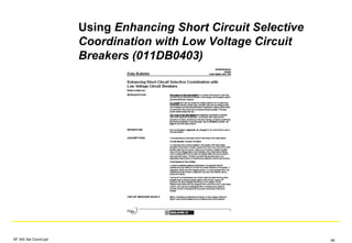
  • 59. Challenges Meeting the NEC Examples of Code Modifications State of California – Healthcare facilities come under the jurisdiction of OSHPD for plan check and inspection – Proposals – 700.27 Coordination. Emergency system(s) overcurrent devices shall be selectively coordinated with all supply side overcurrent protective devices. [Not permitted for OSHPD 1, 2, 3, & 4] – 701.18 Coordination. Legally required standby system(s) overcurrent devices shall be selectively coordinated with all supply side overcurrent protective devices. [Not permitted for OSHPD 1, 2, 3, & 4] SF IAS Sel Coord.ppt 59
  • 60. Challenges Meeting the NEC Examples of Code Modifications State of Wisconsin – Proposals – 517.26 Application of Other Articles. The essential electrical system shall meet the requirements of Article 700, except as amended by Article 517. Essential electrical system(s) overcurrent devices shall be selectively coordinated with all supply side overcurrent protective devices for faults with a duration of 0.1 seconds and longer. The selection and coordination of the overcurrent devices shall be documented and stamped by a professional engineer and approved by the engineer of record for the project. This study and all associated documentation shall be made available for review by the authority having jurisdiction. SF IAS Sel Coord.ppt 60
  • 61. Challenges Meeting the NEC Examples of Code Modifications State of Wisconsin – Proposals – 700.27 Coordination. – Emergency system(s) overcurrent devices shall be selectively coordinated with all supply side overcurrent protective devices for faults with a duration of 0.1 seconds and longer. – 701.18 Coordination. – Legally required standby system(s) overcurrent devices shall be selectively coordinated with all supply side overcurrent protective devices for faults with a duration of 0.1 seconds and longer. – 708.54 Coordination. – Critical operations power system(s) overcurrent devices shall be selectively coordinated with all supply side overcurrent protective devices for faults with a duration of 0.1 seconds and longer. – Exceptions: – (1) Between transformer primary and secondary overcurrent protective devices, where only one overcurrent protective device or set of overcurrent protective devices exists on the transformer secondary, – (2) Between overcurrent protective devices of the same size (ampere rating) in series. SF IAS Sel Coord.ppt 61
  • 62. Challenges Meeting the NEC Examples of Code Modifications New York City – Question (from a consulting engineer dated 9/26/07) “The NEC sections 700.27 and 701.18 require that ‘Emergency System(s) overcurrent devices shall be selectively coordinated with all supply side overcurrent protective devices.’ Does this mean that all the emergency system overcurrent devices, from the smallest branch to the power supply, must be selectively coordinated?” – Answer (from the NYC Electrical Code Revision and Interpretation Committee dated 9/15/07) “Selective coordination requirements for short-circuit conditions are defined in section 240.12. Emergency system(s) overcurrent devices, per section 700.27, shall be selectively coordinated for overcurrent conditions only.” SF IAS Sel Coord.ppt 62
  • 63. Challenges Meeting the NEC Examples of Code Modifications New York City NYC Electrical Code (based on the 2005 NEC) Section 240.12 - Revise to read as follows: 240.12 Electrical System Coordination. Rating and arrangement of service overcurrent devices, which have a rating above 601 amperes, shall be selectively coordinated. Such coordination shall provide a system of selective short circuit and overload protection between the service overcurrent protection and the second level overcurrent protection point. Where an orderly shutdown is required to minimize the hazard(s) to personnel and equipment, an additional overcurrent protection level is permitted. A system of coordination based on the following two conditions shall be permitted: (1) Coordinated short-circuit protection (2) Overload indication based on monitoring systems or devices. SF IAS Sel Coord.ppt 63
  • 64. Challenges Meeting the NEC Examples of Code Modifications New York City New York City Electrical Code (based on the 2005 NEC) Section 240.12 - Revise to read as follows: 240.12 Electrical System Coordination. Exception No. 1: Service overcurrent devices which supply single loads (i.e., motors) shall not require coordination. Exception No. 2: Coordination between the service overcurrent device and distribution main shall not be required where the service disconnecting means supplies a single main overcurrent device for a single distribution panel or switchboard. However, selective coordination shall be required between distribution branch devices, and between the service equipment and the main panel. Exception No. 3: The provisions of this Section shall not apply to the operation of ground fault protection equipment. SF IAS Sel Coord.ppt 64
  • 65. Challenges Meeting the NEC Examples of Enforcement State of Washington – Selective coordination must be assured by a state licensed PE – The Department of Labor and Industries is interpreting the Code to mean that selective coordination is required only to the alternate source City of Tacoma – Selective coordination must be assured by a state licensed PE. A coordination study need not be submitted. (unconfirmed) City of Denver – Selective coordination required only to the alternate source (unconfirmed) SF IAS Sel Coord.ppt 65
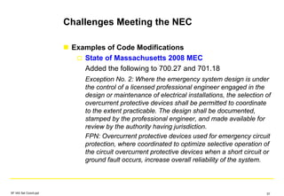
  • 66. Challenges Meeting the NEC Cautions Make sure automatic transfer switches have adequate withstand ratings – May need to relocate the switch, or – May need to increase the frame size of the switch Make sure busway has adequate withstand ratings Make sure the generator protection devices coordinate with the downstream circuit breakers Total ground fault selective coordination may not be possible, or may be difficult, due to other Code requirements [517.17(B)(1) and (2)] SF IAS Sel Coord.ppt 66
  • 67. Challenges Meeting the NEC Cautions Mixing Overcurrent Protective Devices – Mixing OCPDs from different manufacturers or mixing fuses and circuit breakers requires using TCCs only – Fuse ratio or circuit breaker tables cannot be used Arc Flash – Selective coordination impact on arc flash PPE levels needs to be considered – May be possible to reduce with Zone Selective Interlocking SF IAS Sel Coord.ppt 67
  • 68. Definition NEC Selective Coordination Requirements The Challenge Circuit Breaker Principles Resources from the Manufacturers Challenges Meeting the NEC Design Guidelines Example Summary SF IAS Sel Coord.ppt 68
  • 69. Design Guidelines Conduct a Selective Coordination Study First Before letting a job out for bid, conduct a selective coordination study first as it may affect the system design Work from the Bottom Up Starting from the bottom of the system, coordinate the branch lighting panels first, then the power distribution panels, then the switchboard or switchgear SF IAS Sel Coord.ppt 69
  • 70. Design Guidelines Nest Curves The time-current curve of a thermal- magnetic circuit breaker can sometimes be nested underneath the time-current curve of an upstream electronic trip circuit breaker Name: PD-0006 Manufacturer: *SQUARE D Type: EG Frame/Model: 20A Trip: 20 A Voltage: 480 V Settings: Phase Fixed Name: PD-0001 Manufacturer: SQUARED Type: POWERPACT P-Frame, 3.0 & 3.0A Frame/Model: PG Trip: 250 A Voltage: 480 V Settings: Phase LTPU/LTD (A 0.4-1.0 x S) 1 (250A); 0.5 INST PG 250-1200 (1.5-12 X S) 6 (1500A) Name: PD-0006 Manufacturer: *SQUARE D Type: EG Frame/Model: 20A Trip: 20 A Voltage: 480 V Settings: Phase Fixed Name: PD-0001 Manufacturer: SQUARED Type: POWERPACT P-Frame, 3.0 & 3.0A Frame/Model: PG Trip: 250 A Voltage: 480 V Settings: Phase LTPU/LTD (A 0.4-1.0 x S) 1 (250A); 0.5 INST PG 250-1200 (1.5-12 X S) 6 (1500A) SF IAS Sel Coord.ppt 70
  • 71. Design Guidelines Use the Short Circuit Selective Coordination Tables Rather than the Time-Current Curves Feeding Lighting Panelboards Don’t feed lighting panelboards from lighting panelboards unless there is a transformer in between Other Lighting Panelboard Recommendations Better levels of selective coordination are available with 225A and larger panelboards Consider using main lugs panels SF IAS Sel Coord.ppt 71
  • 72. Design Guidelines Increase the Frame Size of the Upstream Circuit Breaker The upstream circuit breaker should be at least one frame size larger than the downstream circuit breaker. This may necessitate increasing the size of panelboards and feeder conductors. Very high levels of short circuit selective coordination may be achieved by using high amp frame electronic trip circuit breakers with low amp sensors and/or lower ampere rating adjustments SF IAS Sel Coord.ppt 72
  • 73. Design Guidelines SF IAS Sel Coord.ppt 73 Rarely needed, but as a last resort... Change the Upstream Circuit Breaker Type Insulated case circuit breakers or low voltage power circuit breakers Reduce the Voltage If the desired level of selective coordination cannot be achieved using a 480Y/277Vac panelboard, consider feeding a 208Y/120Vac panelboard through a transformer Split Up Some of the Loads (multiple smaller transformers) Insert Impedance Longer run of wire, 1:1 or higher impedance transformer or reactors
  • 74. Design Guidelines Generator Protection Selective coordination is sometimes difficult or impossible while providing adequate generator protection Be wary of circuit breakers supplied with engine- generator sets – They are often thermal-magnetic or electronic trip with LI protection – They may need to be electronic trip with LS protection and high withstand if possible, or ANSI LV power circuit breakers Make sure generator protective relays or controls will coordinate with the downstream devices SF IAS Sel Coord.ppt 74
  • 75. Design Guidelines Challenge: CB1 and CB2 must both be selective with CB3, CB4, CB5 and all downstream breakers (CB6…) G CB 1 G CB 2 AUTOXFER SW CB 4 TO NORMAL SOURCE E N CB 3 AUTOXFER SW E N AUTOXFER SW CB 5 E N CB 6 SF IAS Sel Coord.ppt 75
  • 76. Design Guidelines One solution: More, smaller generators without paralleling G CB 1 G AUTOXFER SW TO NORMAL SOURCE E NAUTOXFER SW E N AUTOXFER SW E N CB 6 G Expensive! Decreases reliability Not always practical SF IAS Sel Coord.ppt 76
  • 77. Design Guidelines Better solution: Allow paralleling switchgear feeders to provide short- circuit protection Supplement with bus-differential protection for the generator paralleling bus Not a “cure-all”, but it does often help SF IAS Sel Coord.ppt 77
  • 78. G CB 1 G CB 2 AUTOXFER SW CB 4 TO NORMAL SOURCE E N CB 3 AUTOXFER SW E N AUTOXFER SW CB 5 E N CB 6 87B PROTECTIVE ZONE CB1 and CB2 set to provide overload, but not short-circuit, protection for the generators These settings allow coordination with CBs on the level of CB3 Bus differential protection provides short circuit protection for the generators for faults on generator paralleling bus CBs on CB3 level provide short circuit protection for generators Design Guidelines SF IAS Sel Coord.ppt 78
  • 79. Design Guidelines Selective coordination requires an extremely high level of analysis Often not possible to achieve on conventional designs without major reconfiguration (cannot succeed with device selections alone) Expect significantly higher design time, space requirements, and equipment costs Vendor-Specific Design Difficult to delegate the design to a vendor by specifying “vendor shall provide fully selective equipment” because of effects on equipment sizes, room sizes, system layout strategy, feeder sizes, etc. Bogue Waller, P.E., Principal Electrical Engineer, Nash Lipsey Burch, LLC, Nashville, TN SF IAS Sel Coord.ppt 79
  • 80. Design Guidelines Field Adjustment Don’t neglect to properly adjust circuit breakers in the field as they are often shipped from the factory with all but the ampere-rating switch in the lowest position SF IAS Sel Coord.ppt 80
  • 81. Definition NEC Selective Coordination Requirements Circuit Breaker Principles Resources from the Manufacturers Design Guidelines Challenges Meeting the NEC Example Summary SF IAS Sel Coord.ppt 81
  • 82. Example Which of these circuit breakers need to be selectively coordinated? SF IAS Sel Coord.ppt 82
  • 83. Example Which of these circuit breakers need to be selectively coordinated? #3 must coordinate with #4 because it is a supply side device Yes SF IAS Sel Coord.ppt 83
  • 84. Example Which of these circuit breakers need to be selectively coordinated? #1 does not need to coordinate with #3, assuming that they are both the same size, in accordance with Exception 2 in the 2008 NEC which states, "Exception: Selective coordination shall not be required in (1) or (2): (2) Between overcurrent protective devices of the same size (ampere rating) in series." #1 does need to coordinate with #4 and the other breakers on that bus. (Note: While this exception does not exist in the 2005 NEC, most engineers would come to this same conclusion, and most AHJs would probably agree.) No Yes SF IAS Sel Coord.ppt 84
  • 85. Example Which of these circuit breakers need to be selectively coordinated? #A does not need to coordinate with #1 or 3, however, it does need to coordinate with #4 because it is a supply side device No Yes SF IAS Sel Coord.ppt 85
  • 86. Example Which of these circuit breakers need to be selectively coordinated? #2 does not need to coordinate with #3, assuming that they are both the same size, but it does need to coordinate with #4 and the other breakers on that bus No YesYes SF IAS Sel Coord.ppt 86
  • 87. Example Which of these circuit breakers need to be selectively coordinated? #A, #B and #C are not required to be coordinated in accordance with the scope of Article 700 and drawing B.1 in NFPA 110 Annex B This illustrates the problem with requiring coordination up to the normal source – if the normal loads are not coordinated, has the emergency system reliability really been improved? No No SF IAS Sel Coord.ppt 87
  • 88. Definition NEC Selective Coordination Requirements Circuit Breaker Principles Resources from the Manufacturers Design Guidelines Challenges Meeting the NEC Example Summary SF IAS Sel Coord.ppt 88
  • 89. Summary Understand the NEC Selective coordination requirements How the AHJ will interpret and enforce them Understand the Operating Characteristics of Circuit Breakers Limitations of the TCCs in the short circuit zone SF IAS Sel Coord.ppt 89
  • 90. Summary Understand the Design Characteristics of Circuit Breakers Withstand Capability Instantaneous Trip Setting Field adjustable instantaneous adjustment can be turned OFF on LSI and LSIG trip units Continuous Current Rating Overlap Allows for selecting a larger frame size breaker, particularly on electronic trip circuit breakers SF IAS Sel Coord.ppt 90
  • 91. Summary Evaluation Methodology Conduct a short circuit study (from both sources) Make initial circuit breaker selections Determine the selective coordination levels Optimizing Techniques Use the short circuit selective coordination tables rather than the TCCs if there is an overlap of the TCCs in the short circuit zone Consider better system configurations Increase the frame size of the upstream breakers Change the upstream breaker type Add impedance to reduce short circuit current levels SF IAS Sel Coord.ppt 91
  • 92. Summary Low voltage circuit breaker based systems can be selectively coordinated! Thank You! Questions? SF IAS Sel Coord.ppt 92