SlideShare a Scribd company logo
UNIT-III
TRANSMISSION SYSTEMS
Transmission System
• Transmission System is the system by means
of which power developed by the engine is
transmitted to road wheels to propel the
vehicle.
• In Automobile the power developed by the
engine which is used to turn wheel. Therefore
the engine is connected to the transmission.
Transmission Arrangement
Purpose of Transmission system
• It enables the running engine to be connected
or disconnected from the driving wheel
smoothly and without shocks.
• It enables the reduction of engine speed.
• It enables the driving wheels to driven at
different speeds.
CLUTCH
Characteristics of a clutch
• Transmission of torque
• Gradual engagement
• Dissipation of heat
• Dynamic balancing
• Vibration damping
• Size of the clutch
• Free pedal clutch play
• Non-exertive operation of disengagement
Clutch
• Clutch is a mechanism used to connect or
disconnect the engine from the rest of
transmission elements.
• It is located between engine and gear box.
• During normal running and stationary
position, it is always in engaged condition.
• It is always in engaged condition.
Principle of Operation of friction clutch
TYPES OF CLUTCH
1. Friction clutch
a) single plate clutch
b)Multi plate clutch
• Wet type
• Dry type
c) cone clutch
2. Centrifugal clutch
3. Semi centrifugal clutch
4. Coil pressure spring clutch
5. Conical spring clutch or diaphragm clutch
a) Tapered
b) Crown spring
6. Positive clutch- dog and spline clutch
7. Hydraulic clutch
Single plate clutch
Single plate Clutch
• It is most commonly used in motor vehicle
such as cars, trucks and tractors.
• Various parts of Single plate Clutch-
1. Fly wheel.
2. Pilot Bearing.
3. Clutch plate.
4. Pressure plate.
5. Clutch cover assembly.
Transmission system of Automobiles
Multi-plate Clutch
• Multi-plate clutch are used in heavy vehicles
racing cars and motorcycles for transmitting
high torque.
• They are smooth and easy to operate due to
their assembly of friction surface’s contact.
• This clutch are of two types wet type and dry
type.
MULTI PLATE CLUTCH
Multi-plate clutch
• The wet type clutch plate are oil immersed
clutch this types of wet clutches are generally
used in conjunction with a part of automatic
transmission.
• advantages –
1. It is highly reliable.
2. It is suitable for heavy vehicles.
3. Increased torque transmission capacity could
be obtained .
Cone clutch
• The cone surface of this type of clutch are in
form of cone. It is called cone clutch.
• It consist of two cones having two leather
facing.
• This cones are known as male and female
cone.
• One cone is fixed to the driving member and
other cone is fixed to the splined driven shaft.
CONE CLUTCH
Cone clutch
Advantages-
• Normal force acting on the contact surface is
larger than the axial force which reduces the
effort required to operate the clutch.
Disadvantages-
• If the angle of cone is smaller than 20’, the
male cone tends to bind or joint in the female
cone.
Centrifugal clutch
• Centrifugal clutch is controlled by the engine
speed through an accelerator. When the
speed decrease the clutch gets disengage.
• When the speed rises above the
predetermined value the clutch is engaged.
Greater is the centrifugal force due to higher
engine speed, more will be powerful contact.
CENTRIFUGAL CLUTCH
Semi centrifugal clutch
• In this clutch plate the pressure between
plates is increased as the speed of rotation of
the clutch in proportional to the pressure
requirements.
• As speed increases, the rotating weights will
tend to move the pressure plate towards the
flywheel.
• The ends of release levers are also moved
back against the throw out bearing along with
this movement of the pressure plate.
SEMI CENTRIFUGAL CLUTCH
DIAPHRAGM CLUTCH
POSITIVE CLUTCH OR DOG AND SPLINE
CLUTCH
HYDRAULIC CLUTCH
ELECTROMAGNETIC CLUTCH
Gear box
• Gear box is a speed and torque changing
device. It changes speed and torque between
engine and driving wheels.
• More power is required to keep an
automobile in motion when compared to
power required for keeping it rolling after
starting.
Gear box
• Necessity of Gear box-
When the vehicle is running, various
resistance oppose it. In order to keep vehicle
moving at uniform speed , a driving force or
tractive effort is equal to the sum of all opposing
force.
Purpose of transmission
• It helps the engine to disconnect from driving
wheels.
• It helps the running engine to be connected to
the driving wheel smoothly and without
shock.
• It provides the leverage between engine and
driving wheels to be varied.
• It helps the driving wheels to be driven at
different speed.
Tractive effort
• The torque available on the wheel produce a
driving force which is parallel to the end known
as tractive effort.
GEAR BOX
TYPES OF GEAR BOX
1.Manual transmission
a) Sliding mesh gearbox
b) Constant mesh gear box
c) Synchromesh gear box
2. Epicyclic gear box
3. Automatic gear box
a) Hydromatic gear box
b) Torque converter gear box
Sliding mesh Gear Box
• Sliding mesh gear box is a transmission system
that consist of various sets of gears and shafts
that are arranged together in an organized
fashion and the shifting or meshing of
different gear ratios is done by the sliding of
gears towards right and left over the splined
shaft with the help of a gear lever operated by
the driver.
Need of sliding mesh transmission
• Fuel consumption of an automobile increased
as the load on the engine is decreased.
• Due to varying torque ratio provided by this
gearbox, the automobile vehicle is made to go
to the hill stations which is possible earlier.
• Reverse of the car made possible with the
introduction of this transmission system.
Sliding mesh gear box
First Gear
Second Gear
3rd gear
4th gear
Application
• Alfa 12HP used sliding mesh gearbox with 4 -
speed manual transmission.
• Fiat 6HP used 3-speed manual transmission.
• Mercedes 35HP used 4-speed manual
transmission
• Renault Voiturette used manual 3-speed
transmission.
Constant Mesh Gear Box
• Constant Mesh Gearbox is type of transmission in
which all or most of the gears are always in mesh
with one another, as opposed to a sliding gear
transmission, in which engagement is obtained by
sliding some of the gears along the shaft into
mesh.
• In constant mesh gear box, Gear ratios are
selected by the small clutches that are connect
the various gear sets to their shaft so power is
transmitted through them.
Constant mesh gear box
Transmission system of Automobiles
Constant mesh gear box
Synchromesh Gear Box
• To simplify the operation of changing of gear
without the occurrence of clashes and their
consequent damage, synchromesh is used in
different motors.
• The main feature of this gear box is
The main shaft or output gear is freely
rotated on the bushes of the output shaft.
Advantages and Disadvantages
• Gear Changing is very much simplified.
• Less wear in gear.
• It allows the usage of helical gear that run
directly.
Disadvantages
The design is very much complex.
Automatic Gear Box
• Various speed are obtained automatically in
gear boxes are known as automatic gear box,
generally the driver selects the car condition
such as neutral , forward or reverse.
• Such Gear box are of two types
• Hydramatic Transmission.
• Torque convertor transmission.
AUTOMATIC GEARBOX
HYDROMATIC TRANSMISSION
First Gear
• The power transmitted from the flywheel to
the torus covers, then to the internal gear and
to the planet cage with the sun gear when the
front unit is locked thus the engine is running.
• The planet cage usually moves around the
stationary sun gear with reduced speed. The
power is transmitted by the cage to the
driving torus through the front section of the
intermediate shaft.
Second Gear
• The power is first transmitted to the torus
covers and then to the locked front unit from
the flywheel.
• The front section of the intermediate shaft
transmit the power directly to the fluid
flywheel. Then it is transmitted back to sun
gear of the rear section.
Third gear
• Now the gear is 1.45 :1, similarly the front unit
is engaged, the planet cage is driven by the
driven internal gear.
Fourth Gear
• The direct Drive is obtained by controlling the
transmission in the front unit.
• The power is transmitted from the flywheel
through the torus covers to the locked front
unit. Now the power is transmitted from the
flywheel through the torus covers to the
locked front unit. The power is transmitted in
two paths.
Shift or Selector Mechanism
• For Gear Changing and selecting a particular
gear train to operation, the selector
mechanism is implemented to obtained the
same easier.
• In this case, the gear are shifted by a gearshift
Lever. In Manually operated selective
transmission system, the gear shift lever is
mounted either on the steering column or
floor board.
SHIFT OR SELECTOR MECHANISM
(a) FLOOR MOUNTED SHIFT MECHANISM
(b) MECHANISM WITH GEAR LEVER AS STEERING
COLUMN
Over drive Mechanism
• In this the high gear mechanism produces 1:1
ratio Between clutch gear and transmission
output shaft.
• There is neither gear reduction nor gear
increase through the Transmission. It is the
direct drive.
• It produces the high cruising speed with
comparative low engine speed.
Over drive Mechanism
• The shift to overdrive can be obtained when
the car is running above a predetermined cut
in speed from 32 to 51 km/hr by lifting the
foot momentarily from the accelerator. The
action of the overdrive is controlled by a
centrifugally operated switch.
OVERDRIVE MECHANISM
Transfer Box
• Transfer Box is a part of a four wheel drive
system used in four wheel drive or all wheel
drive vehicles. It is also called as transfer gear
case.
• Function of Transfer Gear box-
1. It receives power front the transmission and
sends to both front and rear axles.
2. It provides low and high range of speed.
TRANSFER BOX
Transfer Box
• Type of transfer Box-
• Gear driven type transfer box.
• Chain driven type transfer box.
• Housing type gear box.
• Transfer case shift typee.
Fluid flywheel
• It is also known as fluid clutch, which couples
the driving members with driven member
through the media of fluid.
• Advantages-
• It is simple design.
• No need of adjustment is required.
• No skill is required for operation.
FLUID FLYWHEEL
Torque convertor
• The only difference is that it has an additional
stationary member called ‘ Stator or reaction
member”.
• But the operation is not similar. In the case of
flywheel, the same torque is transmitted as
given by the engine shaft.
Torque Convertor
• Single stage torque convertor-
1. Impeller or driving member- This is driving
member is connected to the engine.
2. Turbine or Driven member- This driven
member is connected to the road wheels
through the transmission gears and the drive
line and
3. Stator- It is connected to the frame through a
free wheel.
TORQUE CONVERTER
Transmission system of Automobiles
UNIVERSAL JOINTS
Propeller Shaft
• The propeller Shaft is connected between
transmission shaft (i.e. gear box output shaft and
pinion shaft) of the differential at the wheel axle.
• The propeller shaft also called as driveline shaft
or drive shaft.
• The propeller shaft takes power from the engine
and a transmits to clutch, transmission gear box
unit and driving wheels of the vehicle through the
final drive and differential units.
PROPELLER SHAFT
SLIP JOINTS
Differential
• Differential is a system that transmits an
engine’s torque to the wheels. The differential
takes the power from the engine and splits it,
allowing the wheels to spin at different
speeds.
• Major Components of differential-
1. Drive pinion or bevel pinion.
2. Ring Gear or Crown wheel.
3. Differential Case.
4. Differential side gear or Sun gears.
Type of Differential
• Conventional Differential.
• Limited Slip Differential.
• Non Slip Differential.
• Double Reduction differential
DIFFERENTIAL
DIFFERENTIAL
Limited Slip Differential or Self Locking
Differential
Non Slip Differential
• The differential is a torque controlled
differential. Preloading the system is possible.
• The Differential is operated by resultant
moments. Preload can be adjusted.
Advantages-
I. Maximum Traction can be achieved for all
grip levels.
II. Fuel Consumption is reduced.
Non Slip Differential
Rear Axle
• The power transmitted through rear axle to
driving wheels. On Modern passenger cars
almost all rear axles are live axles.
• It includes revolving shafts for driving wheels.
In ordinary cars, the live axle will be at the
front and the rear axle will be dead which
simply remains stationary.
Rear Axle
• All live axle shafts are splitted into two parts in
modern cars. Each part is driven by one of the
differential gears through a spline connection.
• Types of Rear Axle-
1. Dead Axle.
2. Live Axle.
CONSTRUCTION OF REAR AXLES
TYPES OF REAR AXLES
(i) SEMI FLOATING AXLE
(ii)FULL FLOATING AXLE
(iii) THREE QUARTER FLOATING AXLE
REAR AXLE DRIVES
(i) HOTCHKISS DRIVE
(ii) TORQUE TUBE DRIVE

More Related Content

PPTX
Study of transmission system of automobile
PPTX
Power transmission in Automobiles
PPT
Manual transmission system in automobiles
PPTX
Synchromesh gear box
PPTX
Transmission system
PDF
Gearbox in automobile
PPTX
Gear box
PPTX
Automobile transmission - Gear Box
Study of transmission system of automobile
Power transmission in Automobiles
Manual transmission system in automobiles
Synchromesh gear box
Transmission system
Gearbox in automobile
Gear box
Automobile transmission - Gear Box

What's hot (20)

PPTX
Propeller shaft & universal joint
PPT
Braking systems
PPTX
rear axle ppt
PPTX
Presentation on Transmission System
PPTX
Propeller shaft
PPTX
Transmission systems
PPTX
PPTX
Electronic ignition system
PPT
clutch.ppt
PPTX
Battery Ignition System
PPTX
Clutches
PPTX
Clutches ( Single Plate and Multi Plate)
PPTX
Governor used in vehicles
PPTX
I.C.Engine performance parameters
PPTX
Automobiles steering systems
PPTX
Petrol injection system
PPTX
Steering System
PPTX
Clutch ppt
PPT
Differential
PPTX
Steering geometry 8
Propeller shaft & universal joint
Braking systems
rear axle ppt
Presentation on Transmission System
Propeller shaft
Transmission systems
Electronic ignition system
clutch.ppt
Battery Ignition System
Clutches
Clutches ( Single Plate and Multi Plate)
Governor used in vehicles
I.C.Engine performance parameters
Automobiles steering systems
Petrol injection system
Steering System
Clutch ppt
Differential
Steering geometry 8
Ad

Similar to Transmission system of Automobiles (20)

PPTX
Types of Transmission
PPTX
PPTX
Gear box- transmission system of automobiles
PPTX
Automobile transmission.pptx
PPTX
gearbox Arrangement with proper Diagram.pptx
PPTX
transmission_1.pptx
PDF
Automatic Transmission System
PPTX
Transmission system. Describe construction & working of varius automobile sys...
PDF
Gear box
PPT
Transmission system in an automobile
PDF
Gear box classisfication
PDF
Automotive transmission system
PPTX
Automatic transmission (torque converter)
PPT
Automotive transmission mechanism
PPTX
UNIT-III-TRANSMISSION SYSTEMS REAR AXLES
PPTX
UNIT-III-TRANSMISSION SYSTEMS.pptx
PPTX
UNIT-III-TRANSMISSION SYSTEMS.pptx
PPTX
gear box - heart of automobile
PPTX
transmition system.pptx
PPT
Transmission system
Types of Transmission
Gear box- transmission system of automobiles
Automobile transmission.pptx
gearbox Arrangement with proper Diagram.pptx
transmission_1.pptx
Automatic Transmission System
Transmission system. Describe construction & working of varius automobile sys...
Gear box
Transmission system in an automobile
Gear box classisfication
Automotive transmission system
Automatic transmission (torque converter)
Automotive transmission mechanism
UNIT-III-TRANSMISSION SYSTEMS REAR AXLES
UNIT-III-TRANSMISSION SYSTEMS.pptx
gear box - heart of automobile
transmition system.pptx
Transmission system
Ad

More from PraveenManickam2 (20)

PPTX
2D Drafting in computer aided drafting or modeling
PPTX
Basic of Design in Computer aided Drawing and Computer aided Machining
PDF
Chemical and Electro Chemical Based process
PPTX
Thermal and Electrical Energy based processes
PPTX
UCM Unit-1
PPTX
Basics of UCM
PPTX
AJM and WJM
PPTX
EDM and Wire Cut EDM
PPTX
Electro Chemical Machining Process
PPTX
Ultrasonic Machining Process
PPTX
Abrasive Jet Machining Process and Water Machining Process
PPTX
CNC Part Program
PPT
case hardening
PPTX
heat treatment
PPTX
PPTX
iron carbon system
PPTX
cast iron
PPTX
cooling curve
PPTX
Phase Diagram
2D Drafting in computer aided drafting or modeling
Basic of Design in Computer aided Drawing and Computer aided Machining
Chemical and Electro Chemical Based process
Thermal and Electrical Energy based processes
UCM Unit-1
Basics of UCM
AJM and WJM
EDM and Wire Cut EDM
Electro Chemical Machining Process
Ultrasonic Machining Process
Abrasive Jet Machining Process and Water Machining Process
CNC Part Program
case hardening
heat treatment
iron carbon system
cast iron
cooling curve
Phase Diagram

Recently uploaded (20)

PDF
How much does a e145 excavator weight.pdf
DOCX
lp of food hygiene.docxvvvvvvvvvvvvvvvvvvvvvvv
PDF
industrial engineering and safety system
PPTX
vsdfhlahsadfjkhasihdflakjsdfhlajdhlfkjahfdljkash
PDF
Volvo ecr88 lifting capacity Service Repair Manual.pdf
PPTX
Intro to ISO 9001 2015.pptx for awareness
PDF
Volvo ecr145cl specs Service Manual Download
PPTX
Fire Fighting Unit IV industrial safety.pptx
PDF
Volvo ecr88 battery location Service Repair Manual.pdf
PDF
120725175041.pdfhjjjjjjjjjjjjjjjjjjjjjjh
PPTX
TOEFL ITP Grammar_ Clausessssssssssssssssss.pptx
PDF
What are dimensions of the Volvo ECR235cl.pdf
PDF
Journal Meraj.pdfuuuuuuuuuuuuuuuuuuuuuuuuuuuuuuu
PPTX
1. introduction-to-bvcjdhjdfffffffffffffffffffffffffffffffffffmicroprocessors...
PDF
Physics class 12thstep down transformer project.pdf
PPTX
Chapter-1.pptxhhhhhhhhhhhhhhhhhhhhhhhhhh
PPT
ACCOMPLISHMENT REPOERTS AND FILE OF GRADE 12 2021.ppt
PDF
Caterpillar Cat 315C Excavator (Prefix CJC) Service Repair Manual Instant Dow...
PPTX
Materi Kuliah Umum Prof. Hsien Tsai Wu.pptx
PDF
Caterpillar CAT 312B L EXCAVATOR (2KW00001-UP) Operation and Maintenance Manu...
How much does a e145 excavator weight.pdf
lp of food hygiene.docxvvvvvvvvvvvvvvvvvvvvvvv
industrial engineering and safety system
vsdfhlahsadfjkhasihdflakjsdfhlajdhlfkjahfdljkash
Volvo ecr88 lifting capacity Service Repair Manual.pdf
Intro to ISO 9001 2015.pptx for awareness
Volvo ecr145cl specs Service Manual Download
Fire Fighting Unit IV industrial safety.pptx
Volvo ecr88 battery location Service Repair Manual.pdf
120725175041.pdfhjjjjjjjjjjjjjjjjjjjjjjh
TOEFL ITP Grammar_ Clausessssssssssssssssss.pptx
What are dimensions of the Volvo ECR235cl.pdf
Journal Meraj.pdfuuuuuuuuuuuuuuuuuuuuuuuuuuuuuuu
1. introduction-to-bvcjdhjdfffffffffffffffffffffffffffffffffffmicroprocessors...
Physics class 12thstep down transformer project.pdf
Chapter-1.pptxhhhhhhhhhhhhhhhhhhhhhhhhhh
ACCOMPLISHMENT REPOERTS AND FILE OF GRADE 12 2021.ppt
Caterpillar Cat 315C Excavator (Prefix CJC) Service Repair Manual Instant Dow...
Materi Kuliah Umum Prof. Hsien Tsai Wu.pptx
Caterpillar CAT 312B L EXCAVATOR (2KW00001-UP) Operation and Maintenance Manu...

Transmission system of Automobiles

  • 2. Transmission System • Transmission System is the system by means of which power developed by the engine is transmitted to road wheels to propel the vehicle. • In Automobile the power developed by the engine which is used to turn wheel. Therefore the engine is connected to the transmission.
  • 4. Purpose of Transmission system • It enables the running engine to be connected or disconnected from the driving wheel smoothly and without shocks. • It enables the reduction of engine speed. • It enables the driving wheels to driven at different speeds.
  • 5. CLUTCH Characteristics of a clutch • Transmission of torque • Gradual engagement • Dissipation of heat • Dynamic balancing • Vibration damping • Size of the clutch • Free pedal clutch play • Non-exertive operation of disengagement
  • 6. Clutch • Clutch is a mechanism used to connect or disconnect the engine from the rest of transmission elements. • It is located between engine and gear box. • During normal running and stationary position, it is always in engaged condition. • It is always in engaged condition.
  • 7. Principle of Operation of friction clutch
  • 8. TYPES OF CLUTCH 1. Friction clutch a) single plate clutch b)Multi plate clutch • Wet type • Dry type c) cone clutch 2. Centrifugal clutch 3. Semi centrifugal clutch 4. Coil pressure spring clutch 5. Conical spring clutch or diaphragm clutch a) Tapered b) Crown spring 6. Positive clutch- dog and spline clutch 7. Hydraulic clutch
  • 10. Single plate Clutch • It is most commonly used in motor vehicle such as cars, trucks and tractors. • Various parts of Single plate Clutch- 1. Fly wheel. 2. Pilot Bearing. 3. Clutch plate. 4. Pressure plate. 5. Clutch cover assembly.
  • 13. Multi-plate Clutch • Multi-plate clutch are used in heavy vehicles racing cars and motorcycles for transmitting high torque. • They are smooth and easy to operate due to their assembly of friction surface’s contact. • This clutch are of two types wet type and dry type.
  • 15. Multi-plate clutch • The wet type clutch plate are oil immersed clutch this types of wet clutches are generally used in conjunction with a part of automatic transmission. • advantages – 1. It is highly reliable. 2. It is suitable for heavy vehicles. 3. Increased torque transmission capacity could be obtained .
  • 16. Cone clutch • The cone surface of this type of clutch are in form of cone. It is called cone clutch. • It consist of two cones having two leather facing. • This cones are known as male and female cone. • One cone is fixed to the driving member and other cone is fixed to the splined driven shaft.
  • 18. Cone clutch Advantages- • Normal force acting on the contact surface is larger than the axial force which reduces the effort required to operate the clutch. Disadvantages- • If the angle of cone is smaller than 20’, the male cone tends to bind or joint in the female cone.
  • 19. Centrifugal clutch • Centrifugal clutch is controlled by the engine speed through an accelerator. When the speed decrease the clutch gets disengage. • When the speed rises above the predetermined value the clutch is engaged. Greater is the centrifugal force due to higher engine speed, more will be powerful contact.
  • 21. Semi centrifugal clutch • In this clutch plate the pressure between plates is increased as the speed of rotation of the clutch in proportional to the pressure requirements. • As speed increases, the rotating weights will tend to move the pressure plate towards the flywheel.
  • 22. • The ends of release levers are also moved back against the throw out bearing along with this movement of the pressure plate.
  • 25. POSITIVE CLUTCH OR DOG AND SPLINE CLUTCH
  • 28. Gear box • Gear box is a speed and torque changing device. It changes speed and torque between engine and driving wheels. • More power is required to keep an automobile in motion when compared to power required for keeping it rolling after starting.
  • 29. Gear box • Necessity of Gear box- When the vehicle is running, various resistance oppose it. In order to keep vehicle moving at uniform speed , a driving force or tractive effort is equal to the sum of all opposing force.
  • 30. Purpose of transmission • It helps the engine to disconnect from driving wheels. • It helps the running engine to be connected to the driving wheel smoothly and without shock. • It provides the leverage between engine and driving wheels to be varied. • It helps the driving wheels to be driven at different speed.
  • 31. Tractive effort • The torque available on the wheel produce a driving force which is parallel to the end known as tractive effort.
  • 32. GEAR BOX TYPES OF GEAR BOX 1.Manual transmission a) Sliding mesh gearbox b) Constant mesh gear box c) Synchromesh gear box 2. Epicyclic gear box 3. Automatic gear box a) Hydromatic gear box b) Torque converter gear box
  • 33. Sliding mesh Gear Box • Sliding mesh gear box is a transmission system that consist of various sets of gears and shafts that are arranged together in an organized fashion and the shifting or meshing of different gear ratios is done by the sliding of gears towards right and left over the splined shaft with the help of a gear lever operated by the driver.
  • 34. Need of sliding mesh transmission • Fuel consumption of an automobile increased as the load on the engine is decreased. • Due to varying torque ratio provided by this gearbox, the automobile vehicle is made to go to the hill stations which is possible earlier. • Reverse of the car made possible with the introduction of this transmission system.
  • 40. Application • Alfa 12HP used sliding mesh gearbox with 4 - speed manual transmission. • Fiat 6HP used 3-speed manual transmission. • Mercedes 35HP used 4-speed manual transmission • Renault Voiturette used manual 3-speed transmission.
  • 41. Constant Mesh Gear Box • Constant Mesh Gearbox is type of transmission in which all or most of the gears are always in mesh with one another, as opposed to a sliding gear transmission, in which engagement is obtained by sliding some of the gears along the shaft into mesh. • In constant mesh gear box, Gear ratios are selected by the small clutches that are connect the various gear sets to their shaft so power is transmitted through them.
  • 48. Synchromesh Gear Box • To simplify the operation of changing of gear without the occurrence of clashes and their consequent damage, synchromesh is used in different motors. • The main feature of this gear box is The main shaft or output gear is freely rotated on the bushes of the output shaft.
  • 49. Advantages and Disadvantages • Gear Changing is very much simplified. • Less wear in gear. • It allows the usage of helical gear that run directly. Disadvantages The design is very much complex.
  • 50. Automatic Gear Box • Various speed are obtained automatically in gear boxes are known as automatic gear box, generally the driver selects the car condition such as neutral , forward or reverse. • Such Gear box are of two types • Hydramatic Transmission. • Torque convertor transmission.
  • 52. First Gear • The power transmitted from the flywheel to the torus covers, then to the internal gear and to the planet cage with the sun gear when the front unit is locked thus the engine is running. • The planet cage usually moves around the stationary sun gear with reduced speed. The power is transmitted by the cage to the driving torus through the front section of the intermediate shaft.
  • 53. Second Gear • The power is first transmitted to the torus covers and then to the locked front unit from the flywheel. • The front section of the intermediate shaft transmit the power directly to the fluid flywheel. Then it is transmitted back to sun gear of the rear section.
  • 54. Third gear • Now the gear is 1.45 :1, similarly the front unit is engaged, the planet cage is driven by the driven internal gear.
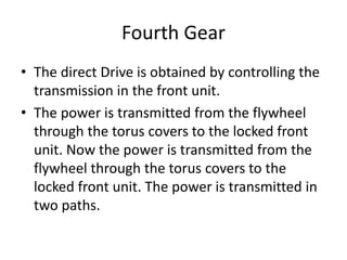
  • 55. Fourth Gear • The direct Drive is obtained by controlling the transmission in the front unit. • The power is transmitted from the flywheel through the torus covers to the locked front unit. Now the power is transmitted from the flywheel through the torus covers to the locked front unit. The power is transmitted in two paths.
  • 56. Shift or Selector Mechanism • For Gear Changing and selecting a particular gear train to operation, the selector mechanism is implemented to obtained the same easier. • In this case, the gear are shifted by a gearshift Lever. In Manually operated selective transmission system, the gear shift lever is mounted either on the steering column or floor board.
  • 57. SHIFT OR SELECTOR MECHANISM (a) FLOOR MOUNTED SHIFT MECHANISM
  • 58. (b) MECHANISM WITH GEAR LEVER AS STEERING COLUMN
  • 59. Over drive Mechanism • In this the high gear mechanism produces 1:1 ratio Between clutch gear and transmission output shaft. • There is neither gear reduction nor gear increase through the Transmission. It is the direct drive. • It produces the high cruising speed with comparative low engine speed.
  • 60. Over drive Mechanism • The shift to overdrive can be obtained when the car is running above a predetermined cut in speed from 32 to 51 km/hr by lifting the foot momentarily from the accelerator. The action of the overdrive is controlled by a centrifugally operated switch.
  • 62. Transfer Box • Transfer Box is a part of a four wheel drive system used in four wheel drive or all wheel drive vehicles. It is also called as transfer gear case. • Function of Transfer Gear box- 1. It receives power front the transmission and sends to both front and rear axles. 2. It provides low and high range of speed.
  • 64. Transfer Box • Type of transfer Box- • Gear driven type transfer box. • Chain driven type transfer box. • Housing type gear box. • Transfer case shift typee.
  • 65. Fluid flywheel • It is also known as fluid clutch, which couples the driving members with driven member through the media of fluid. • Advantages- • It is simple design. • No need of adjustment is required. • No skill is required for operation.
  • 67. Torque convertor • The only difference is that it has an additional stationary member called ‘ Stator or reaction member”. • But the operation is not similar. In the case of flywheel, the same torque is transmitted as given by the engine shaft.
  • 68. Torque Convertor • Single stage torque convertor- 1. Impeller or driving member- This is driving member is connected to the engine. 2. Turbine or Driven member- This driven member is connected to the road wheels through the transmission gears and the drive line and 3. Stator- It is connected to the frame through a free wheel.
  • 72. Propeller Shaft • The propeller Shaft is connected between transmission shaft (i.e. gear box output shaft and pinion shaft) of the differential at the wheel axle. • The propeller shaft also called as driveline shaft or drive shaft. • The propeller shaft takes power from the engine and a transmits to clutch, transmission gear box unit and driving wheels of the vehicle through the final drive and differential units.
  • 75. Differential • Differential is a system that transmits an engine’s torque to the wheels. The differential takes the power from the engine and splits it, allowing the wheels to spin at different speeds. • Major Components of differential- 1. Drive pinion or bevel pinion. 2. Ring Gear or Crown wheel. 3. Differential Case. 4. Differential side gear or Sun gears.
  • 76. Type of Differential • Conventional Differential. • Limited Slip Differential. • Non Slip Differential. • Double Reduction differential
  • 79. Limited Slip Differential or Self Locking Differential
  • 80. Non Slip Differential • The differential is a torque controlled differential. Preloading the system is possible. • The Differential is operated by resultant moments. Preload can be adjusted. Advantages- I. Maximum Traction can be achieved for all grip levels. II. Fuel Consumption is reduced.
  • 82. Rear Axle • The power transmitted through rear axle to driving wheels. On Modern passenger cars almost all rear axles are live axles. • It includes revolving shafts for driving wheels. In ordinary cars, the live axle will be at the front and the rear axle will be dead which simply remains stationary.
  • 83. Rear Axle • All live axle shafts are splitted into two parts in modern cars. Each part is driven by one of the differential gears through a spline connection. • Types of Rear Axle- 1. Dead Axle. 2. Live Axle.
  • 85. TYPES OF REAR AXLES (i) SEMI FLOATING AXLE
  • 87. (iii) THREE QUARTER FLOATING AXLE
  • 88. REAR AXLE DRIVES (i) HOTCHKISS DRIVE