Uml2 super.book.040324
1 like3,033 views

This document provides the UML 2.0 Superstructure Specification. It defines the syntax and semantics of various UML constructs such as classes, components, associations, interfaces, etc. through a set of normative references, terms and definitions, class descriptions and diagrams. The specification is published by the Object Management Group for industry practitioners to standardize on a common modeling language.


![generalization of a concept is a concept (e.g., a class) that is immediately above it in the hierarchy of its ancestors (i.e.,
its “parent”). Note that these items are hyperlinked in electronic versions of the document to facilitate navigation
through the metamodel class hierarchy. Readers of hardcopy versions can use the page numbers listed with the names
to rapidly locate the description of the superclass. This sub-section is omitted for enumerations.
• A more detailed description of the purpose, nature, and potential usage of the concept may be provided in the “Descrip-
tion” sub-section. This too is informal. If a concept is defined in multiple increments, then the first part of the descrip-
tion covers the top-level package and is followed, in turn, by successive description increments for each sub-package.
The individual increments are identified by a sub-package heading such as
Package PowerTypes
This indicates that the text that follows the heading describes the increment that was added in the PowerTypes sub-
package. The description continues either until the end of the sub-section or until the next sub-package increment
heading is encountered.
This convention for describing sub-package increments is applied to all other sub-sections related to the concept.
• The “Attributes” sub-section of a concept description lists each of the attributes that are defined for that metaclass.
Each attribute is specified by its formal name, its type, and multiplicity. If no multiplicity is listed, it defaults to 0..*.
This is followed by a textual description of the purpose and meaning of the attribute. If an attribute is derived, the name
will be preceded by a slash.
For example:
• body: String[1] Specifies a string that is the comment
specifies an attribute called “body” whose type is “String” and whose multiplicity is 1.
If an attribute is derived, where possible, the definition will also include a specification (usually expressed as an OCL
constraint) specifying how that attribute is derived. For instance:
• /isComposite : Boolean A state with isComposite = true is said to be a composite state. A composite state is a state
that contains at least one region>
isComposite = (region > 1)
• The “Associations” sub-section lists all the association ends owned by the concept. The format for these is the same as
the one for attributes described above. Association ends that are specializations or redefinitions of other association
ends in superclasses are flagged appropriately. For example:
For example:
• lowerValue: ValueSpecification[0..1] {subsets Element::ownedElement}The specification of the lower bound for this
multiplicity.
specifies an association end called “lowerValue” that is connected to the “ValueSpecification” class and whose multi-
plicity is 0..1. Furthermore, it is a specialization of the “ownedElement” association end of the class “Element”.
As with derived attributes, if an association end is derived, where possible, the definition will also include a specifica-
tion (usually expressed as an OCL constraint) specifying how that association end is derived.
• The “Constraints” sub-section contains a numerical list of all the constraints that define additional well-formedness
rules that apply to this concept. Each constraint consists of a textual description and may be followed by a formal con-
straint expressed in OCL. Note that in a few cases, it may not be possible to express the constraint in OCL, in which
case the formal expression is omitted.
6 UML Superstructure 2.0 Draft Adopted Specification](https://image.slidesharecdn.com/uml2-super-book-040324-120914042238-phpapp02/85/Uml2-super-book-040324-22-320.jpg)


![7.2.1 Comment (from Kernel)
A comment is a textual annotation that can be attached to a set of elements.
Description
A comment gives the ability to attach various remarks to elements. A comment carries no semantic force, but may contain
information that is useful to a modeler.
A comment can be owned by any element.
Attributes
• body: String Specifies a string that is the comment.
Associations
• annotatedElement: Element[*] References the Element(s) being commented.
Constraints
No additional constraints.
Semantics
A Comment adds no semantics to the annotated elements, but may represent information useful to the reader of the model.
Notation
A Comment is shown as a rectangle with the upper right corner bent (this is also known as a “note symbol”). The rectangle
contains the body of the Comment. The connection to each annotated element is shown by a separate dashed line.
Presentation Options
The dashed line connecting the note to the annotated element(s) may be suppressed if it is clear from the context, or not
important in this diagram.
Examples
This class was added
by Alan Wright after
meeting with the
mission planning team. Account
Figure 5 - Comment notation
7.2.2 DirectedRelationship (from Kernel)
A directed relationship represents a relationship between a collection of source model elements and a collection of target
model elements.
16 UML Superstructure 2.0 Draft Adopted Specification](https://image.slidesharecdn.com/uml2-super-book-040324-120914042238-phpapp02/85/Uml2-super-book-040324-32-320.jpg)
![Description
A directed relationship references one or more source elements and one or more target elements. Directed relationship is an
abstract metaclass.
Attributes
No additional attributes.
Associations
• / source: Element [1..*] Specifies the sources of the DirectedRelationship. Subsets Relationship::relatedEle-
ment. This is a derived union.
• / target: Element [1..*] Specifies the targets of the DirectedRelationship. Subsets Relationship::relatedElement.
This is a derived union.
Constraints
No additional constraints.
Semantics
DirectedRelationship has no specific semantics. The various subclasses of DirectedRelationship will add semantics
appropriate to the concept they represent.
Notation
There is no general notation for a DirectedRelationship. The specific subclasses of DirectedRelationship will define their own
notation. In most cases the notation is a variation on a line drawn from the source(s) to the target(s).
7.2.3 Element (from Kernel)
An element is a constituent of a model. As such, it has the capability of owning other elements.
Description
Element is an abstract metaclass with no superclass. It is used as the common superclass for all metaclasses in the
infrastructure library. Element has a derived composition association to itself to support the general capability for elements
to own other elements.
Attributes
No additional attributes.
Associations
• ownedComment: Comment[*] The Comments owned by this element. Subsets Element::ownedElement.
• / ownedElement: Element[*] The Elements owned by this element. This is a derived union.
• / owner: Element [0..1] The Element that owns this element. This is a derived union.
UML Superstructure 2.0 Draft Adopted Specification 17](https://image.slidesharecdn.com/uml2-super-book-040324-120914042238-phpapp02/85/Uml2-super-book-040324-33-320.jpg)
![Constraints
[1] An element may not directly or indirectly own itself.
not self.allOwnedElements()->includes(self)
[2] Elements that must be owned must have an owner.
self.mustBeOwned() implies owner->notEmpty()
Additional Operations
[1] The query allOwnedElements() gives all of the direct and indirect owned elements of an element.
Element::allOwnedElements(): Set(Element);
allOwnedElements = ownedElement->union(ownedElement->collect(e | e.allOwnedElements()))
[2] The query mustBeOwned() indicates whether elements of this type must have an owner. Subclasses of Element that do
not require an owner must override this operation.
Element::mustBeOwned() : Boolean;
mustBeOwned = true
Semantics
Subclasses of Element provide semantics appropriate to the concept they represent. The comments for an Element add no
semantics but may represent information useful to the reader of the model.
Notation
There is no general notation for an Element. The specific subclasses of Element define their own notation.
7.2.4 Relationship (from Kernel)
Relationship is an abstract concept that specifies some kind of relationship between elements.
Description
A relationship references one or more related elements. Relationship is an abstract metaclass.
Attributes
No additional attributes.
Associations
• / relatedElement: Element [1..*]Specifies the elements related by the Relationship. This is a derived union.
Constraints
No additional constraints.
Semantics
Relationship has no specific semantics. The various subclasses of Relationship will add semantics appropriate to the concept
they represent.
Notation
There is no general notation for a Relationship. The specific subclasses of Relationship will define their own notation. In most
cases the notation is a variation on a line drawn between the related elements.
18 UML Superstructure 2.0 Draft Adopted Specification](https://image.slidesharecdn.com/uml2-super-book-040324-120914042238-phpapp02/85/Uml2-super-book-040324-34-320.jpg)
![7.3 Kernel – the Namespaces Diagram
The Namespaces diagram of the Kernel package is shown in Figure 6.
E l e me n t
< < e n u m e ra ti o n > >
V i si b i l i ty K i n d
N a me d E l e me n t
p u b lic
n a m e : S tri n g [0 ..1 ]
p ri v a te
v i si b i l i ty : V i si b i l i ty K i n d [0 ..1 ]
p ro te c te d
/ q u a l i fi e d N a m e : S tri n g [0 ..1 ]
p a c ka g e
+ /m e m b e r N a me d E l e me n t
P a c k a g e a b l e E l e me n t N a me s p a c e
+ /i m p o rte d M e m b e r
{u n i o n } *
v i si b i l i ty : V i si b i l i ty K i n d
* {su b se ts m e m b e r}
+ /n a m e sp a c e + /o w n e d M e m b e r
D ir ec te d R e l a tio n s hi p
0 ..1 {u n i o n , {u n i o n , *
s ub s et s ow n e r} su b se ts m e m b e r,
su b se ts o w n e d E l e m e n t}
+ i m p o rte d E l e m e n t
+ i m p o rti n g N a m e sp a c e + e l e m e n tIm p o rt E l e m e n tIm p o rt
P a c k a g e a b l e E l e me n t
v i si b i l i ty : V i si b i l i ty K i n d {su b se ts ta rg e t} 1
{s u bs e ts so u rc e , {s u bs e ts o w ne d E l e m e nt }
1
su b se ts o w n e r}
* a l i a s : S tri n g [0 ..1 ]]
[0 ..1
D i r ec te d R e la ti o n s hi p
+ i m p o rti n gN a m e sp a c e + p a c ka g e Im p o rt + i m p o rte d P a c ka g e
P a c ka g e Im p o rt
P a c ka g e
v i si b i l i ty : V i si b i l i ty K i n d
1 {su b se ts so u rc e , {su b se ts o w n e d E l e m e n t} * {su b se ts ta rg e t} 1
su b se ts o w n e r}
Figure 6 - The Namespaces diagram of the Kernel package
In order to locate the metaclasses that are referenced from this diagram,
• See “DirectedRelationship (from Kernel)” on page 16.
• See “Element (from Kernel)” on page 17.
• See “Package (from Kernel)” on page 88.
7.3.1 ElementImport (from Kernel)
An element import identifies an element in another package, and allows the element to be referenced using its name without a
qualifier.
Description
An element import is defined as a directed relationship between an importing namespace and a packageable element. The
name of the packageable element or its alias is to be added to the namespace of the importing namespace. It is also possible to
control whether the imported element can be further imported.
Attributes
• visibility: VisibilityKind Specifies the visibility of the imported PackageableElement within the importing Package.
The default visibility is the same as that of the imported element. If the imported element
does not have a visibility, it is possible to add visibility to the element import.
• alias: String [0..1] Specifies the name that should be added to the namespace of the importing Pack-age in
lieu of the name of the imported PackagableElement. The aliased name must not clash
with any other member name in the importing Package. By default, no alias is used.
UML Superstructure 2.0 Draft Adopted Specification 19](https://image.slidesharecdn.com/uml2-super-book-040324-120914042238-phpapp02/85/Uml2-super-book-040324-35-320.jpg)
![Associations
• importedElement: PackageableElement [1]Specifies the PackageableElement whose name is to be added to a Namespace.
Subsets DirectedRelationship::target.
• importingNamespace: Namespace [1]Specifies the Namespace that imports a PackageableElement from another Package.
Subsets DirectedRelationship::source and Element::owner.
Constraints
[1] The visibility of an ElementImport is either public or private.
self.visibility = #public or self.visibility = #private
[2] An importedElement has either public visibility or no visibility at all.
self.importedElement.visibility.notEmpty() implies self.importedElement.visibility = #public
Additional Operations
[1] The query getName() returns the name under which the imported PackageableElement will be known in the importing
namespace.
ElementImport::getName(): String;
getName =
if self.alias->notEmpty() then
self.alias
else
self.importedElement.name
endif
Semantics
An element import adds the name of a packageable element from a package to the importing namespace. It works by
reference, which means that it is not possible to add features to the element import itself, but it is possible to modify the
referenced element in the namespace from which it was imported. An element import is used to selectively import individual
elements without relying on a package import.
Issue 6164 - misc. typos
In case of a nameclash with an outer name (an element that is defined in an enclosing namespace is available using its
unqualified name in enclosed namespaces) in the importing namespace, the outer name is hidden by an element import, and
the unqualified name refers to the imported element. The outer name can be accessed using its qualified name.
If more than one element with the same name would be imported to a namespace as a consequence of element imports or
package imports, the names of the imported elements must be qualified in order to be used and the elements are not added to
the importing namespace. If the name of an imported element is the same as the name of an element owned by the importing
namespace, the name of the imported element must be qualified in order to be used and is not added to the importing
namespace.
An imported element can be further imported by other namespaces using either element or member imports.
The visibility of the ElementImport may be either the same or more restricted than that of the imported element.
Notation
An element import is shown using a dashed arrow with an open arrowhead from the importing namespace to the imported
element. The keyword «import» is shown near the dashed arrow if the visibility is public, otherwise the key-word «access» is
shown.
20 UML Superstructure 2.0 Draft Adopted Specification](https://image.slidesharecdn.com/uml2-super-book-040324-120914042238-phpapp02/85/Uml2-super-book-040324-36-320.jpg)

![Description
A named element represents elements that may have a name. The name is used for identification of the named element within
the namespace in which it is defined. A named element also has a qualified name that allows it to be unambiguously identified
within a hierarchy of nested namespaces. NamedElement is an abstract metaclass.
Attributes
• name: String [0..1] The name of the NamedElement.
• / qualifiedName: String [0..1] A name which allows the NamedElement to be identified within a hierarchy of nested
Namespaces. It is constructed from the names of the containing namespaces starting at the
root of the hierarchy and ending with the name of the NamedElement itself. This is a
derived attribute.
• visibility: VisibilityKind [0..1] Determines the visibility of the NamedElement within different Namespaces within the
overall model.
Package Dependencies (“Dependencies” on page 94)
• supplierDependency: Dependency [*]Indicates the dependencies that reference the supplier.
• clientDependency: Dependency[*]Indicates the dependencies that reference the client.
Associations
• / namespace: Namespace [0..1] Specifies the namespace that owns the NamedElement. Subsets Element::owner. This is a
derived union.
Constraints
[1] If there is no name, or one of the containing namespaces has no name, there is no qualified name.
(self.name->isEmpty() or self.allNamespaces()->select(ns | ns.name->isEmpty())->notEmpty())
implies self.qualifiedName->isEmpty()
[2] When there is a name, and all of the containing namespaces have a name, the qualified name is constructed from the
names of the containing namespaces.
(self.name->notEmpty() and self.allNamespaces()->select(ns | ns.name->isEmpty())->isEmpty()) implies
self.qualifiedName = self.allNamespaces()->iterate( ns : Namespace; result: String = self.name |
ns.name->union(self.separator())->union(result))
[3] If a NamedElement is not owned by a Namespace, it does not have a visibility.
namespace->isEmpty() implies visibility->isEmpty()
Additional Operations
[1] The query allNamespaces() gives the sequence of namespaces in which the NamedElement is nested, working outwards.
NamedElement::allNamespaces(): Sequence(Namespace);
allNamespaces =
if self.namespace->isEmpty()
then Sequence{}
else self.name.allNamespaces()->prepend(self.namespace)
endif
22 UML Superstructure 2.0 Draft Adopted Specification](https://image.slidesharecdn.com/uml2-super-book-040324-120914042238-phpapp02/85/Uml2-super-book-040324-38-320.jpg)
![[2] The query isDistinguishableFrom() determines whether two NamedElements may logically co-exist within a Namespace.
By default, two named elements are distinguishable if (a) they have unrelated types or (b) they have related types but dif-
ferent names.
NamedElement::isDistinguishableFrom(n:NamedElement, ns: Namespace): Boolean;
isDistinguishable =
if self.oclIsKindOf(n.oclType) or n.oclIsKindOf(self.oclType)
then ns.getNamesOfMember(self)->intersection(ns.getNamesOfMember(n))->isEmpty()
else true
endif
[3] The query separator() gives the string that is used to separate names when constructing a qualified name.
NamedElement::separator(): String;
separator = ‘::’
Semantics
The name attribute is used for identification of the named element within namespaces where its name is accessible. Note that
the attribute has a multiplicity of [ 0..1 ] which provides for the possibility of the absence of a name (which is different from
the empty name).
The visibility attribute provides the means to constrain the usage of a named element in different namespaces within a model.
It is intended for use in conjunction with import and generalization mechanisms.
Notation
No additional notation.
7.3.3 Namespace (from Kernel)
A namespace is an element in a model that contains a set of named elements that can be identified by name.
Description
A namespace is a named element that can own other named elements. Each named element may be owned by at most one
namespace. A namespace provides a means for identifying named elements by name. Named elements can be identified by
name in a namespace either by being directly owned by the namespace or by being introduced into the namespace by other
means e.g. importing or inheriting. Namespace is an abstract metaclass.
A namespace can own constraints. The constraint does not necessarily apply to the namespace itself, but may also apply to
elements in the namespace.
A namespace has the ability to import either individial members or all members of a package, thereby making it possible to
refer to those named elements without qualification in the importing namespace. In the case of conflicts, it is necessary to use
qualified names or aliases to disambiguate the referenced elements.
Attributes
No additional attributes.
UML Superstructure 2.0 Draft Adopted Specification 23](https://image.slidesharecdn.com/uml2-super-book-040324-120914042238-phpapp02/85/Uml2-super-book-040324-39-320.jpg)
![Associations
• elementImport: ElementImport [*]References the ElementImports owned by the Namespace. Subsets Ele-
ment::ownedElement.
• / importedMember: PackageableElement [*] References the PackageableElements that are members of this Namespace as
a result of either PackageImports or ElementImports. Subsets Namespace::member.
• / member: NamedElement [*] A collection of NamedElements identifiable within the Namespace, either by being owned
or by being introduced by importing or inheritance. This is a derived union.
• / ownedMember: NamedElement [*]A collection of NamedElements owned by the Namespace. Subsets Ele-
ment::ownedElement and Namespace::member. This is a derived union.
• ownedRule: Constraint[*] Specifies a set of Constraints owned by this Namespace. Subsets Namespace::owned-
Member.
• packageImport: PackageImport [*] References the PackageImports owned by the Namespace. Subsets Ele-
ment::ownedElement.
Constraints
[1] All the members of a Namespace are distinguishable within it.
membersAreDistinguishable()
[2] The importedMember property is derived from the ElementImports and the PackageImports.
self.importedMember->includesAll(self.importedMembers(self.elementImport.importedElement.asSet()-
>union(self.packageImport.importedPackage->collect(p | p.visibleMembers()))))
Additional Operations
[1] The query getNamesOfMember() gives a set of all of the names that a member would have in a Namespace. In general a
member can have multiple names in a Namespace if it is imported more than once with different aliases. The query takes
account of importing. It gives back the set of names that an element would have in an importing namespace, either
because it is owned, or if not owned then imported individually, or if not individually then from a package.
Namespace::getNamesOfMember(element: NamedElement): Set(String);
getNamesOfMember =
if self.ownedMember ->includes(element)
then Set{}->include(element.name)
else let elementImports: ElementImport = self.elementImport->select(ei | ei.importedElement = element) in
if elementImports->notEmpty()
then elementImports->collect(el | el.getName())
else
self.packageImport->select(pi | pi.importedPackage.visibleMembers()->includes(element))->
collect(pi | pi.importedPackage.getNamesOfMember(element))
endif
endif
[2] The Boolean query membersAreDistinguishable() determines whether all of the namespace’s members are distinguisha-
ble within it.
Namespace::membersAreDistinguishable() : Boolean;
membersAreDistinguishable =
self.member->forAll( memb |
self.member->excluding(memb)->forAll(other |
memb.isDistinguishableFrom(other, self)))
24 UML Superstructure 2.0 Draft Adopted Specification](https://image.slidesharecdn.com/uml2-super-book-040324-120914042238-phpapp02/85/Uml2-super-book-040324-40-320.jpg)
![[3] The query importMembers() defines which of a set of PackageableElements are actually imported into the namespace.
This excludes hidden ones, i.e., those which have names that conflict with names of owned members, and also excludes
elements which would have the same name when imported.
Namespace::importMembers(imps: Set(PackageableElement)): Set(PackageableElement);
importMembers = self.excludeCollisions(imps)->select(imp | self.ownedMember->forAll(mem |
mem.imp.isDistinguishableFrom(mem, self)))
[4] The query excludeCollisions() excludes from a set of PackageableElements any that would not be distinguishable from
each other in this namespace.
Namespace::excludeCollisions(imps: Set(PackageableElements)): Set(PackageableElements);
excludeCollisions = imps->reject(imp1 | imps.exists(imp2 | not imp1.isDistinguishableFrom(imp2, self)))
Semantics
A namespace provides a container for named elements. It provides a means for resolving composite names, such as
name1::name2::name3. The member association identifies all named elements in a namespace called N that can be referred to
by a composite name of the form N::<x>. Note that this is different from all of the names that can be referred to unqualified
within N, because that set also includes all unhidden members of enclosing namespaces.
Named elements may appear within a namespace according to rules that specify how one named element is distinguishable
from another. The default rule is that two elements are distinguishable if they have unrelated types, or related types but
different names. This rule may be overridden for particular cases, such as operations which are distinguished by their
signature.
The ownedRule constraints for a Namespace represent well formedness rules for the constrained elements. These constraints
are evaluated when determining if the model elements are well formed.
Notation
No additional notation. Concrete subclasses will define their own specific notation.
7.3.4 PackageableElement (from Kernel)
A packageable element indicates a named element that may be owned directly by a package.
Description
A packageable element indicates a named element that may be owned directly by a package.
Attributes
• visibility: VisibilityKind [1] Indicates that packageable elements must always have a visibility, i.e., visibility is not
optional. Redefines NamedElement::visibility.
Associations
No additional associations.
Constraints
No additional constraints.
Semantics
No additional semantics.
UML Superstructure 2.0 Draft Adopted Specification 25](https://image.slidesharecdn.com/uml2-super-book-040324-120914042238-phpapp02/85/Uml2-super-book-040324-41-320.jpg)
![Notation
No additional notation.
7.3.5 PackageImport (from Kernel)
A package import is a relationship that allows the use of unqualified names to refer to package members from other
namespaces.
Description
A package import is defined as a directed relationship that identifies a package whose members are to be imported by a
namespace.
Attributes
• visibility: VisibilityKind Specifies the visibility of the imported PackageableElements within the import-ing
Namespace, i.e., whether imported elements will in turn be visible to other packages that
use that importingPackage as an importedPackage. If the PackageImport is public, the
imported elements will be visible outside the package, while if it is private they will not.
By default, the value of visibility is public.
Associations
• importedPackage: Package [1] Specifies the Package whose members are imported into a Namespace. Subsets Directe-
dRelationship::target.
• importingNamespace: Namespace [1]Specifies the Namespace that imports the members from a Package. Subsets Direct-
edRelationship::source and Element::owner.
Constraints
[1] The visibility of a PackageImport is either public or private.
self.visibility = #public or self.visibility = #private
Semantics
A package import is a relationship between an importing namespace and a package, indicating that the importing namespace
adds the names of the members of the package to its own namespace. Conceptually, a package import is equivalent to having
an element import to each individual member of the imported namespace, unless there is already a separately-defined element
import.
Notation
A package import is shown using a dashed arrow with an open arrowhead from the importing namespace to the imported
package. A keyword is shown near the dashed arrow to identify which kind of package import that is intended. The predefined
keywords are «import» for a public package import , and «access» for a private package import.
Presentation options
Issue 6164 - misc. typos
As an alternative to the dashed arrow, it is possible to show an element import by having a text that uniquely identifies the
imported element within curly brackets either below or after the name of the namespace. The textual syntax is then:
26 UML Superstructure 2.0 Draft Adopted Specification](https://image.slidesharecdn.com/uml2-super-book-040324-120914042238-phpapp02/85/Uml2-super-book-040324-42-320.jpg)
![{import <qualifiedName>} or {access <qualifiedName>}
Examples
In Figure 9, a number of package imports are shown. The elements in Types are imported to ShoppingCart, and then further
imported WebShop. However, the elements of Auxiliary are only accessed from ShoppingCart, and cannot be referenced
using unqualified names from WebShop.
Auxiliary
«access»
ShoppingCart
«import» WebShop
Types «import»
Figure 9 - Examples of public and private package imports
7.3.6 VisibilityKind (from Kernel)
VisibilityKind is an enumeration type that defines literals to determine the visibility of elements in a model.
Description
VisibilityKind is an enumeration of the following literal values:
• public
• private
• protected
• package
Additional Operations
[1] The query bestVisibility() examines a set of VisibilityKinds that includes only public and private, and returns public as the
preferred visibility.
VisibilityKind::bestVisibility(vis: Set(VisibilityKind)) : VisibilityKind;
pre: not vis->includes(#protected) and not vis->includes(#package)
bestVisibility = if vis->includes(#public) then #public else #private endif
Semantics
VisibilityKind is intended for use in the specification of visibility in conjunction with, for example, the Imports,
Generalizations and Packages packages. Detailed semantics are specified with those mechanisms. If the Visibility package is
used without those packages, these literals will have different meanings, or no meanings.
• A public element is visible to all elements that can access the contents of the namespace that owns it.
• A private element is only visible inside the namespace that owns it.
• A protected element is visible to elements that have a generalization relationship to the namespace that owns it.
UML Superstructure 2.0 Draft Adopted Specification 27](https://image.slidesharecdn.com/uml2-super-book-040324-120914042238-phpapp02/85/Uml2-super-book-040324-43-320.jpg)
![• A package element is owned by a namespace that is not a package, and is visible to elements that are in the same pack-
age as its owning namespace. Only named elements that are not owned by packages can be marked as having package
visibility. Any element marked as having package element is visible to all elements within the nearest enclosing pack-
age (given that other owning elements have proper visibility). Outside the nearest enclosing package, an element
marked as having package visibility is not visible.
In circumstances where a named element ends up with multiple visibilities, for example by being imported multiple times,
public visibility overrides private visibility, i.e., if an element is imported twice into the same namespace, once using a
public import and once using a private import, it will be public.
7.4 Kernel – the Multiplicities Diagram
The Multiplicities diagram of the Kernel package is shown in Figure 10.
Element
+ownerUpper
MultiplicityElement {subs ets owner} +upperValue
isOrdered : Boolean = false ValueSpecification
0..1 {subset s ownedElement} 0..1
isUnique : Boolean = true
/ upper : UnlimitedNatural [0..1] +ownerLower
{subsets owner} +lowerValue
/ lower : Integer [0..1]
0..1 {subsets ownedElement} 0..1
NamedElement PackageableElement
+type
TypedElement Type
0..1
Figure 10 - The Multiplicities diagram of the Kernel package.
In order to locate the metaclasses that are referenced from this diagram,
• See “Classifier (from Kernel, Dependencies, PowerTypes)” on page 49.
• See “Element (from Kernel)” on page 17.
• See “ValueSpecification (from Kernel)” on page 40.
7.4.1 MultiplicityElement (from Kernel)
A multiplicity is a definition of an inclusive interval of non-negative integers beginning with a lower bound and ending
with a (possibly infinite) upper bound. A multiplicity element embeds this information to specify the allowable
cardinalities for an instantiation of this element.
28 UML Superstructure 2.0 Draft Adopted Specification](https://image.slidesharecdn.com/uml2-super-book-040324-120914042238-phpapp02/85/Uml2-super-book-040324-44-320.jpg)
![Description
A MultiplicityElement is an abstract metaclass which includes optional attributes for defining the bounds of a multiplicity.
A MultiplicityElement also includes specifications of whether the values in an instantiation of this element must be
unique or ordered.
Attributes
• isOrdered: Boolean For a multivalued multiplicity, this attribute specifies whether the values in an instantia-
tion of this element are sequentially ordered. Default is false.
• isUnique : Boolean For a multivalued multiplicity, this attributes specifies whether the values in an instantia-
tion of this element are unique. Default is true.
• / lower : Integer [0..1] Specifies the lower bound of the multiplicity interval, if it is expressed as an integer.
• / upper : UnlimitedNatural [0..1]Specifies the upper bound of the multiplicity interval, if it is expressed as an unlimited
natural.
Associations
• lowerValue: ValueSpecification [0..1]The specification of the lower bound for this multiplicity. Subsets Ele-
ment::ownedElement.
• upperValue: ValueSpecification [0..1]The specification of the upper bound for this multiplicity. Subsets Ele-
ment::ownedElement.
Constraints
These constraint must handle situations where the upper bound may be specified by an expression not computable in the
model.
[1] A multiplicity must define at least one valid cardinality that is greater than zero.
upperBound()->notEmpty() implies upperBound() > 0
[2] The lower bound must be a non-negative integer literal.
lowerBound()->notEmpty() implies lowerBound() >= 0
[3] The upper bound must be greater than or equal to the lower bound.
(upperBound()->notEmpty() and lowerBound()->notEmpty()) implies upperBound() >= lowerBound()
[4] If a non-literal ValueSpecification is used for the lower or upper bound, then evaluating that specification must not have
side effects.
Cannot be expressed in OCL.
[5] If a non-literal ValueSpecification is used for the lower or upper bound, then that specification must be a constant expres-
sion.
Cannot be expressed in OCL.
[6] The derived lower attribute must equal the lowerBound.
lower = lowerBound()
[7] The derived upper attribute must equal the upperBound.
upper = upperBound()
Additional Operations
[1] The query isMultivalued() checks whether this multiplicity has an upper bound greater than one.
UML Superstructure 2.0 Draft Adopted Specification 29](https://image.slidesharecdn.com/uml2-super-book-040324-120914042238-phpapp02/85/Uml2-super-book-040324-45-320.jpg)
![MultiplicityElement::isMultivalued() : Boolean;
pre: upperBound()->notEmpty()
isMultivalued = (upperBound() > 1)
[2] The query includesCardinality() checks whether the specified cardinality is valid for this multiplicity.
MultiplicityElement::includesCardinality(C : Integer) : Boolean;
pre: upperBound()->notEmpty() and lowerBound()->notEmpty()
includesCardinality = (lowerBound() <= C) and (upperBound() >= C)
[3] The query includesMultiplicity() checks whether this multiplicity includes all the cardinalities allowed by the specified
multiplicity.
MultiplicityElement::includesMultiplicity(M : MultiplicityElement) : Boolean;
pre: self.upperBound()->notEmpty() and self.lowerBound()->notEmpty()
and M.upperBound()->notEmpty() and M.lowerBound()->notEmpty()
includesMultiplicity = (self.lowerBound() <= M.lowerBound()) and (self.upperBound() >= M.upperBound())
[4] The query lowerBound() returns the lower bound of the multiplicity as an integer.
MultiplicityElement::lowerBound() : [Integer];
lowerBound = if lowerValue->isEmpty() then 1 else lowerValue.integerValue() endif
[5] The query upperBound() returns the upper bound of the multiplicity for a bounded multiplicity as an unlimited natural.
MultiplicityElement::upperBound() : [UnlimitedNatural];
upperBound = if upperValue->isEmpty() then 1 else upperValue.unlimitedValue() endif
Semantics
A multiplicity defines a set of integers that define valid cardinalities. Specifically, cardinality C is valid for multiplicity M if
M.includesCardinality(C).
A multiplicity is specified as an interval of integers starting with the lower bound and ending with the (possibly infinite) upper
bound.
If a MultiplicityElement specifies a multivalued multiplicity, then an instantiation of this element has a set of values. The
multiplicity is a constraint on the number of values that may validly occur in that set.
If the MultiplicityElement is specified as ordered (i.e. isOrdered is true), then the set of values in an instantiation of this
element is ordered. This ordering implies that there is a mapping from positive integers to the elements of the set of values. If
a MultiplicityElement is not multivalued, then the value for isOrdered has no semantic effect.
If the MultiplicityElement is specified as unordered (i.e. isOrdered is false), then no assumptions can be made about the order
of the values in an instantiation of this element.
If the MultiplicityElement is specified as unique (i.e. isUnique is true), then the set of values in an instantiation of this element
must be unique. If a MultiplicityElement is not multivalued, then the value for isUnique has no semantic effect.
The lower and upper bounds for the multiplicity of a MultiplicityElement may be specified by value specifications, such as
(side-effect free, constant) expressions.
Notation
The specific notation for a MultiplicityElement is defined by the concrete subclasses. In general, the notation will include a
multiplicity specification is shown as a text string containing the bounds of the interval, and a notation for showing the
optional ordering and uniqueness specifications.
The multiplicity bounds are typically shown in the format:
lower-bound..upper-bound
where lower-bound is an integer and upper-bound is an unlimited natural number. The star character (*) is used as part of a
multiplicity specification to represent the unlimited (or infinite) upper bound.
30 UML Superstructure 2.0 Draft Adopted Specification](https://image.slidesharecdn.com/uml2-super-book-040324-120914042238-phpapp02/85/Uml2-super-book-040324-46-320.jpg)
![If the Multiplicity is associated with an element whose notation is a text string (such as an attribute, etc.), the multiplicity
string will be placed within square brackets ([]) as part of that text string. Figure 11 shows two multiplicity strings as part of
attribute specifications within a class symbol.
If the Multiplicity is associated with an element that appears as a symbol (such as an association end), the multiplicity string is
displayed without square brackets and may be placed near the symbol for the element. Figure 12 shows two multiplicity
strings as part of the specification of two association ends.
The specific notation for the ordering and uniqueness specifications may vary depending on the specific subclass of
MultiplicityElement. A general notation is to use a property string containing ordered or unordered to define the ordering, and
unique or nonunique to define the uniqueness.
Presentation Options
If the lower bound is equal to the upper bound, then an alternate notation is to use the string containing just the upper bound.
For example, “1” is semantically equivalent to “1..1”.
A multiplicity with zero as the lower bound and an unspecified upper bound may use the alternative notation containing a
single star “*” instead of “0..*”.
The following BNF defines the syntax for a multiplicity string, including support for the presentation options.
multiplicity ::= <multiplicity_range> [ ‘{‘ <order_designator> ‘}’ ]
multiplicity_range ::= [ lower ‘..’ ] upper
lower ::= integer | value_specification
upper ::= unlimited_natural | ‘*’ | value_specification
<order_designator> ::= ordered | unordered
<uniqueness_designator> ::= unique | nonunique
Examples
Customer
purchase : Purchase [*] {ordered, unique}
account: Account [0..5] {unique}
Figure 11 - Multiplicity within a textual specification
purchase account
Purchase Customer Account
{ordered {unique}
* unique} 0..5
Figure 12 - Multiplicity as an adornment to a symbol
7.4.2 Type (from Kernel)
A type constrains the values represented by a typed element.
UML Superstructure 2.0 Draft Adopted Specification 31](https://image.slidesharecdn.com/uml2-super-book-040324-120914042238-phpapp02/85/Uml2-super-book-040324-47-320.jpg)
![Description
A type serves as a constraint on the range of values represented by a typed element. Type is an abstract metaclass.
Attributes
No additional attributes.
Associations
No additional associations.
Constraints
No additional constraints.
Additional Operations
[1] The query conformsTo() gives true for a type that conforms to another. By default, two types do not conform to each other.
This query is intended to be redefined for specific conformance situations.
conformsTo(other: Type): Boolean;
conformsTo = false
Semantics
A type represents a set of values. A typed element that has this type is constrained to represent values within this set.
Notation
No general notation.
7.4.3 TypedElement (from Kernel)
A typed element has a type.
Description
A typed element is an element that has a type that serves as a constraint on the range of values the element can represent.
Typed element is an abstract metaclass.
Attributes
No additional attributes.
Associations
• type: Type [0..1] The type of the TypedElement.
Constraints
No additional constraints.
Semantics
Values represented by the element are constrained to be instances of the type. A typed element with no associated type may
represent values of any type.
32 UML Superstructure 2.0 Draft Adopted Specification](https://image.slidesharecdn.com/uml2-super-book-040324-120914042238-phpapp02/85/Uml2-super-book-040324-48-320.jpg)
![Notation
No general notation.
7.5 Kernel – the Expressions Diagram
The Expressions diagram of the Kernel package is shown in Figure 13.
TypedElement
+o perand Va lu eSpecifi cati on
{ordered, subsets ownedElement} *
+expression +instance
Expression OpaqueExpression In stanceSpec if icat ion
LiteralSpecification InstanceValue
symbol : String body : String 1
0..1 language : String [0..1]
{subsets owner}
L it eral Bool ean LiteralInteger LiteralString LiteralUnlimitedNatural LiteralNull
value : Boolean val ue : I nteger value : String val ue : Un li mit ed Natura l
Figure 13 - The Expressions diagram of the Kernel package.
In order to locate the metaclasses that are referenced from this diagram,
• See “Element (from Kernel)” on page 17.
• See “InstanceSpecification (from Kernel)” on page 45.
• See “MultiplicityElement (from Kernel)” on page 28.
7.5.1 Expression (from Kernel)
An expression is a structured tree of symbols that denotes a (possibly empty) set of values when evaluated in a context.
Description
An expression represents a node in an expression tree, which may be non-terminal or terminal. It defines a symbol, and has a
possibly empty sequence of operands which are value specifications.
Attributes
• symbol: String [1] The symbol associated with the node in the expression tree.
UML Superstructure 2.0 Draft Adopted Specification 33](https://image.slidesharecdn.com/uml2-super-book-040324-120914042238-phpapp02/85/Uml2-super-book-040324-49-320.jpg)
![Associations
• operand: ValueSpecification[*] Specifies a sequence of operands. Subsets Element::ownedElement.
Constraints
No additional constraints.
Semantics
An expression represents a node in an expression tree. If there are no operands it represents a terminal node. If there are
operands it represents an operator applied to those operands. In either case there is a symbol associated with the node. The
interpretation of this symbol depends on the context of the expression.
Notation
By default an expression with no operands is notated simply by its symbol, with no quotes. An expression with operands is
notated by its symbol, followed by round parentheses containing its operands in order. In particular contexts special notations
may be permitted, including infix operators.
Examples
xor
else
plus(x,1)
x+1
7.5.2 OpaqueExpression (from Kernel)
An opaque expression is an uninterpreted textual statement that denotes a (possibly empty) set of values when evaluated in a
context.
Description
An expression contains a language-specific text string used to describe a value or values, and an optional specification of the
language.
One predefined language for specifying expressions is OCL. Natural language or programming languages may also be used.
Attributes
• body: String [1] The text of the expression.
• language: String [0..1] Specifies the language in which the expression is stated. The interpretation of the expres-
sion body depends on the language. If language is unspecified, it might be implicit from
the expression body or the context.
Associations
No additional associations.
Constraints
No additional constraints.
34 UML Superstructure 2.0 Draft Adopted Specification](https://image.slidesharecdn.com/uml2-super-book-040324-120914042238-phpapp02/85/Uml2-super-book-040324-50-320.jpg)
![Additional Operations
These operations are not defined within the specification of UML. They should be defined within an implementation that
implements constraints so that constraints that use these operations can be evaluated.
[1] The query value() gives an integer value for an expression intended to produce one.
Expression::value(): Integer;
pre: self.isIntegral()
[2] The query isIntegral() tells whether an expression is intended to produce an integer.
Expression::isIntegral(): Boolean;
[3] The query isPositive() tells whether an integer expression has a positive value.
Expression::isPositive(): Boolean;
pre: self.isIntegral()
[4] The query isNonNegative() tells whether an integer expression has a non-negative value.
Expression::isNonNegative(): Boolean;
pre: self.isIntegral()
Semantics
The interpretation of the expression body depends on the language. If the language is unspecified, it might be implicit from the
expression body or the context.
It is assumed that a linguistic analyzer for the specified language will evaluate the body. The time at which the body will be
evaluated is not specified.
Notation
An opaque expression is displayed as a text string in a particular language. The syntax of the string is the responsibility of a
tool and a linguistic analyzer for the language.
An opaque expression is displayed as a part of the notation for its containing element.
The language of an opaque expression, if specified, is often not shown on a diagram. Some modeling tools may impose a
particular language or assume a particular default language. The language is often implicit under the assumption that the form
of the expression makes its purpose clear. If the language name is shown, it should be displayed in braces ({}) before the
expression string.
Style Guidelines
A language name should be spelled and capitalized exactly as it appears in the document defining the language. For example,
use OCL, not ocl.
Examples
a>0
{OCL} i > j and self.size > i
average hours worked per week
7.5.3 InstanceValue (from Kernel)
An instance value is a value specification that identifies an instance.
UML Superstructure 2.0 Draft Adopted Specification 35](https://image.slidesharecdn.com/uml2-super-book-040324-120914042238-phpapp02/85/Uml2-super-book-040324-51-320.jpg)
![Description
An instance value specifies the value modeled by an instance specification.
Attributes
No additional attributes.
Associations
• instance: InstanceSpecification [1]The instance that is the specified value.
Constraints
No additional constraints.
Semantics
The instance specification is the specified value.
Notation
An instance value can appear using textual or graphical notation. When textual, as can appear for the value of an attribute slot,
the name of the instance is shown. When graphical, a reference value is shown by connecting to the instance. See
“InstanceSpecification”.
7.5.4 LiteralBoolean (from Kernel)
A literal boolean is a specification of a boolean value.
Description
A literal boolean contains a Boolean-valued attribute.
Attributes
• value: Boolean The specified Boolean value.
Associations
No additional associations.
Constraints
No additional constraints.
Additional Operations
[1] The query isComputable() is redefined to be true.
LiteralBoolean::isComputable(): Boolean;
isComputable = true
[2] The query booleanValue() gives the value.
LiteralBoolean::booleanValue() : [Boolean];
booleanValue = value
36 UML Superstructure 2.0 Draft Adopted Specification](https://image.slidesharecdn.com/uml2-super-book-040324-120914042238-phpapp02/85/Uml2-super-book-040324-52-320.jpg)
![Semantics
A LiteralBoolean specifies a constant Boolean value.
Notation
A LiteralBoolean is shown as either the word ‘true’ or the word ‘false’, corresponding to its value.
7.5.5 LiteralInteger (from Kernel)
A literal integer is a specification of an integer value.
Description
A literal integer contains an Integer-valued attribute.
Attributes
• value: Integer The specified Integer value.
Associations
No additional associations.
Constraints
No additional constraints.
Additional Operations
[1] The query isComputable() is redefined to be true.
LiteralInteger::isComputable(): Boolean;
isComputable = true
[2] The query integerValue() gives the value.
LiteralInteger::integerValue() : [Integer];
integerValue = value
Semantics
A LiteralInteger specifies a constant Integer value.
Notation
A LiteralInteger is shown as a sequence of digits.
7.5.6 LiteralNull (from Kernel)
A literal null specifies the lack of a value.
Description
A literal null is used to represent null, i.e., the absence of a value.
UML Superstructure 2.0 Draft Adopted Specification 37](https://image.slidesharecdn.com/uml2-super-book-040324-120914042238-phpapp02/85/Uml2-super-book-040324-53-320.jpg)
![Attributes
No additional attributes.
Associations
No additional associations.
Constraints
No additional constraints.
[1] The query isComputable() is redefined to be true.
LiteralNull::isComputable(): Boolean;
isComputable = true
[2] The query isNull() returns true.
LiteralNull::isNull() : Boolean;
isNull = true
Semantics
LiteralNull is intended to be used to explicitly model the lack of a value.
Notation
Notation for LiteralNull varies depending on where it is used. It often appears as the word ‘null’. Other notations are described
for specific uses.
7.5.7 LiteralSpecification (from Kernel)
A literal specification identifies a literal constant being modeled.
Description
A literal specification is an abstract specialization of ValueSpecification that identifies a literal constant being modeled.
Attributes
No additional attributes.
Associations
No additional associations.
Constraints
No additional constraints.
Semantics
No additional semantics. Subclasses of LiteralSpecification are defined to specify literal values of different types.
Notation
No specific notation.
38 UML Superstructure 2.0 Draft Adopted Specification](https://image.slidesharecdn.com/uml2-super-book-040324-120914042238-phpapp02/85/Uml2-super-book-040324-54-320.jpg)
![7.5.8 LiteralString (from Kernel)
A literal string is a specification of a string value.
Description
A literal string contains a String-valued attribute.
Attributes
• value: String The specified String value.
Associations
No additional associations.
Constraints
No additional constraints.
Additional Operations
[1] The query isComputable() is redefined to be true.
LiteralString::isComputable(): Boolean;
isComputable = true
[2] The query stringValue() gives the value.
LiteralString::stringValue() : [String];
stringValue = value
Semantics
A LiteralString specifies a constant String value.
Notation
A LiteralString is shown as a sequence of characters within double quotes.
The character set used is unspecified.
7.5.9 LiteralUnlimitedNatural (from Kernel)
A literal unlimited natural is a specification of an unlimited natural number.
Description
A literal unlimited natural contains a UnlimitedNatural-valued attribute.
Attributes
• value: UnlimitedNatural The specified UnlimitedNatural value.
Associations
No additional associations.
UML Superstructure 2.0 Draft Adopted Specification 39](https://image.slidesharecdn.com/uml2-super-book-040324-120914042238-phpapp02/85/Uml2-super-book-040324-55-320.jpg)
![Constraints
No additional constraints.
Additional Operations
[1] The query isComputable() is redefined to be true.
LiteralUnlimitedNatural::isComputable(): Boolean;
isComputable = true
[2] The query unlimitedValue() gives the value.
LiteralUnlimitedNatural::unlimitedValue() : [UnlimitedNatural];
unlimitedValue = value
Semantics
A LiteralUnlimitedNatural specifies a constant UnlimitedNatural value.
Notation
A LiteralUnlimitedNatural is shown either as a sequence of digits or as an asterisk (*), where an asterisk denotes unlimited
(and not infinity).
7.5.10 ValueSpecification (from Kernel)
A value specification is the specification of a (possibly empty) set of instances, including both objects and data values.
Description
ValueSpecification is an abstract metaclass used to identify a value or values in a model. It may reference an instance or it may
be an expression denoting an instance or instances when evaluated.
Attributes
• expression: Expression[0..1] If this value specification is an operand, the owning expression. Subsets Element::owner.
Associations
No additional associations.
Constraints
No additional constraints.
Additional Operations
These operations are introduced here. They are expected to be redefined in subclasses. Conforming implementations may be
able to compute values for more expressions that are specified by the constraints that involve these operations.
[1] The query isComputable() determines whether a value specification can be computed in a model. This operation cannot be
fully defined in OCL. A conforming implementation is expected to deliver true for this operation for all value specifica-
tions that it can compute, and to compute all of those for which the operation is true. A conforming implementation is
expected to be able to compute the value of all literals.
ValueSpecification::isComputable(): Boolean;
isComputable = false
40 UML Superstructure 2.0 Draft Adopted Specification](https://image.slidesharecdn.com/uml2-super-book-040324-120914042238-phpapp02/85/Uml2-super-book-040324-56-320.jpg)
![[2] The query integerValue() gives a single Integer value when one can be computed.
ValueSpecification::integerValue() : [Integer];
integerValue = Set{}
[3] The query booleanValue() gives a single Boolean value when one can be computed.
ValueSpecification::booleanValue() : [Boolean];
booleanValue = Set{}
[4] The query stringValue() gives a single String value when one can be computed.
ValueSpecification::stringValue() : [String];
stringValue = Set{}
[5] The query unlimitedValue() gives a single UnlimitedNatural value when one can be computed.
ValueSpecification::unlimitedValue() : [UnlimitedNatural];
unlimitedValue = Set{}
[6] The query isNull() returns true when it can be computed that the value is null.
ValueSpecification::isNull() : Boolean;
isNull = false
Semantics
A value specification yields zero or more values. It is required that the type and number of values is suitable for the context
where the value specification is used.
Notation
No specific notation.
7.6 Kernel – the Constraints Diagram
The Constraints diagram of the Kernel package is shown in Figure 14.
PackageableElement
Constraint +constrainedElement Element
Namesp ace +/co ntext
{ordered} *
0..1 {un io n} *
+namespace +owne dRul e +sp eci fi ca ti on ValueSpecification
0..1 {subsets context} {su bse ts o wnedMe mb er} * 0..1 {su bse ts o wnedElemen t} 1
Figure 14 - The Constraints diagram of the Kernel package
In order to locate the metaclasses that are referenced from this diagram,
• See “Element (from Kernel)” on page 17.
• See “Namespace (from Kernel)” on page 23.
• See “PackageableElement (from Kernel)” on page 25.
• See “ValueSpecification (from Kernel)” on page 40.
UML Superstructure 2.0 Draft Adopted Specification 41](https://image.slidesharecdn.com/uml2-super-book-040324-120914042238-phpapp02/85/Uml2-super-book-040324-57-320.jpg)
![7.6.1 Constraint (from Kernel)
A constraint is a condition or restriction expressed in natural language text or in a machine readable language for the purpose
of declaring some of the semantics of an element.
Description
Constraint contains a ValueSpecification that specifies additional semantics for one or more elements. Certain kinds of
constraints (such as an association “xor” constraint) are predefined in UML, others may be user-defined. A user-defined
Constraint is described using a specified language, whose syntax and interpretation is a tool responsibility. One predefined
language for writing constraints is OCL. In some situations, a programming language such as Java may be appropriate for
expressing a constraint. In other situations natural language may be used.
Constraint is a condition (a Boolean expression) that restricts the extension of the associated element beyond what is imposed
by the other language constructs applied to that element.
Constraint contains an optional name, although they are commonly unnamed.
Attributes
No additional attributes.
Associations
• constrainedElement: Element[*]The ordered set of Elements referenced by this Constraint.
• / context: Namespace [0..1] Specifies the Namespace that is the context for evaluating this constraint. This is a
derived union.
• specification: ValueSpecification[0..1]
A condition that must be true when evaluated in order for the constraint to be satisfied.
Subsets Element::ownedElement.
Constraints
[1] The value specification for a constraint must evaluate to a boolean value.
Cannot be expressed in OCL.
[2] Evaluating the value specification for a constraint must not have side effects.
Cannot be expressed in OCL.
[3] A constraint cannot be applied to itself.
not constrainedElement->includes( self )
Semantics
A Constraint represents additional semantic information attached to the constrained elements. A constraint is an assertion that
indicates a restriction that must be satisfied by a correct design of the system. The constrained elements are those elements
required to evaluate the constraint specification. In addition, the context of the Constraint may be accessed, and may be used as
the namespace for interpreting names used in the specification. For example, in OCL ‘self’ is used to refer to the context
element.
Constraints are often expressed as a text string in some language. If a formal language such as OCL is used, then tools may be
able to verify some aspects of the constraints.
In general there are many possible kinds of owners for a Constraint. The only restriction is that the owning element must have
42 UML Superstructure 2.0 Draft Adopted Specification](https://image.slidesharecdn.com/uml2-super-book-040324-120914042238-phpapp02/85/Uml2-super-book-040324-58-320.jpg)
![access to the constrainedElements.
The owner of the Constraint will determine when the constraint specification is evaluated. For example, this allows an
Operation to specify if a Constraint represents a precondition or a postcondition.
Notation
A Constraint is shown as a text string in braces ({}) according to the following BNF:
constraint ::= ‘{‘ [ <name> ‘:’ ] <boolean expression>’ }’
For an element whose notation is a text string (such as an attribute, etc.), the constraint string may follow the element text
string in braces. Figure 15 shows a constraint string that follows an attribute within a class symbol.
For a Constraint that applies to a single element (such as a class or an association path), the constraint string may be placed
near the symbol for the element, preferably near the name, if any. A tool must make it possible to determine the constrained
element.
For a Constraint that applies to two elements (such as two classes or two associations), the constraint may be shown as a
dashed line between the elements labeled by the constraint string (in braces). Figure 16 shows an {xor} constraint between two
associations.
Presentation Options
The constraint string may be placed in a note symbol and attached to each of the symbols for the constrained elements by a
dashed line. Figure 17 shows an example of a constraint in a note symbol.
If the constraint is shown as a dashed line between two elements, then an arrowhead may be placed on one end. The direction
of the arrow is relevant information within the constraint. The element at the tail of the arrow is mapped to the first position
and the element at the head of the arrow is mapped to the second position in the constrainedElements collection.
For three or more paths of the same kind (such as generalization paths or association paths), the constraint may be attached to
a dashed line crossing all of the paths.
UML Superstructure 2.0 Draft Adopted Specification 43](https://image.slidesharecdn.com/uml2-super-book-040324-120914042238-phpapp02/85/Uml2-super-book-040324-59-320.jpg)


![Description
An instance specification specifies existence of an entity in a modeled system and completely or partially describes the entity.
The description may include:
• Classification of the entity by one or more classifiers of which the entity is an instance. If the only classifier specified is
abstract, then the instance specification only partially describes the entity.
• The kind of instance, based on its classifier or classifiers — for example, an instance specification whose classifier is a
class describes an object of that class, while an instance specification whose classifier is an association describes a link
of that association.
• Specification of values of structural features of the entity. Not all structural features of all classifiers of the instance
specification need be represented by slots, in which case the instance specification is a partial description.
• Specification of how to compute, derive or construct the instance (optional).
InstanceSpecification is a concrete class.
Attributes
No additional attributes.
Associations
• classifier : Classifier [0..*] The classifier or classifiers of the represented instance. If multiple classifiers are specified,
the instance is classified by all of them.
• slot : Slot [*] A slot giving the value or values of a structural feature of the instance. An instance speci-
fication can have one slot per structural feature of its classifiers, including inherited fea-
tures. It is not necessary to model a slot for each structural feature, in which case the
instance specification is a partial description. Subsets Element::ownedElement.
• specification : ValueSpecification [0..1]A specification of how to compute, derive, or construct the instance. Subsets Ele-
ment::ownedElement.
Constraints
[1] The defining feature of each slot is a structural feature (directly or inherited) of a classifier of the instance specification.
slot->forAll(s |
classifier->exists(c | c.allFeatures()->includes(s.definingFeature)
)
[2] One structural feature (including the same feature inherited from multiple classifiers) is the defining feature of at most
one slot in an instance specification.
classifier->forAll(c |
(c.allFeatures()->forAll(f | slot->select(s | s.definingFeature = f)->size() <= 1)
)
Semantics
An instance specification may specify the existence of an entity in a modeled system. An instance specification may provide
an illustration or example of a possible entity in a modeled system. An instance specification describes the entity. These details
can be incomplete. The purpose of an instance specification is to show what is of interest about an entity in the modeled
system. The entity conforms to the specification of each classifier of the instance specification, and has features with values
indicated by each slot of the instance specification. Having no slot in an instance specification for some feature does not mean
that the represented entity does not have the feature, but merely that the feature is not of interest in the model.
46 UML Superstructure 2.0 Draft Adopted Specification](https://image.slidesharecdn.com/uml2-super-book-040324-120914042238-phpapp02/85/Uml2-super-book-040324-62-320.jpg)

![association ends.
Don : Person father son Josh : Person
Figure 21 - Instance specifications representing two objects connected by a link
Presentation Options
A slot value for an attribute can be shown using a notation similar to that for a link. A solid path runs from the owning
instance specification to the target instance specification representing the slot value, and the name of the attribute adorns
the target end of the path. Navigability, if shown, must be only in the direction of the target.
7.7.2 Slot (from Kernel)
A slot specifies that an entity modeled by an instance specification has a value or values for a specific structural feature.
Description
A slot is owned by an instance specification. It specifies the value or values for its defining feature, which must be a structural
feature of a classifier of the instance specification owning the slot.
Attributes
No additional attributes.
Associations
• definingFeature : StructuralFeature [1]
The structural feature that specifies the values that may be held by the slot.
• owningInstance : InstanceSpecification [1]
The instance specification that owns this slot. Subsets Element::owner.
• value : InstanceSpecification [*]
The value or values corresponding to the defining feature for the owning instance specifi-
cation. This is an ordered association. Subsets Element::ownedElement.
Constraints
No additional constraints.
Semantics
A slot relates an instance specification, a structural feature, and a value or values. It represents that an entity modeled by the
instance specification has a structural feature with the specified value or values. The values in a slot must conform to the
defining feature of the slot (in type, multiplicity, etc.).
Notation
See “InstanceSpecification (from Kernel)”.
48 UML Superstructure 2.0 Draft Adopted Specification](https://image.slidesharecdn.com/uml2-super-book-040324-120914042238-phpapp02/85/Uml2-super-book-040324-64-320.jpg)

![Associations
• attribute: Property [*] Refers to all of the Properties that are direct (i.e. not inherited or imported) attributes of
the classifier. Subsets Classifier::feature and is a derived union.
• / feature : Feature [*] Specifies each feature defined in the classifier. Subsets Namespace::member. This is a
derived union.
• / general : Classifier[*] Specifies the general Classifiers for this Classifier. This is derived.
• generalization: Generalization[*]Specifies the Generalization relationships for this Classifier. These Generalizations navi-
gate to more general classifiers in the generalization hierarchy. Subsets Ele-
ment::ownedElement.
• / inheritedMember: NamedElement[*]Specifies all elements inherited by this classifier from the general classifiers. Sub-
sets Namespace::member. This is derived.
• package: Package [0..1] Specifies the owning package of this classifier, if any. Subsets NamedEle-
ment::namespace.
• redefinedClassifier: Classifier [*]References the Classifiers that are redefined by this Classifier. Subsets RedefinableEle-
ment::redefinedElement.
Package Dependencies (“Dependencies” on page 94)
• substitution : Substitution References the substitutions that are owned by this Classifier. Subsets Ele-
ment::ownedElement and NamedElement::clientDependency.)
Package PowerTypes (“PowerTypes” on page 109)
• powertypeExtent : GeneralizationSet
Designates the GeneralizationSet of which the associated Classifier is a power type.
Constraints
[1] The general classifiers are the classifiers referenced by the generalization relationships.
general = self.parents()
[2] Generalization hierarchies must be directed and acyclical. A classifier can not be both a transitively general and transi-
tively specific classifier of the same classifier.
not self.allParents()->includes(self)
[3] A classifier may only specialize classifiers of a valid type.
self.parents()->forAll(c | self.maySpecializeType(c))
[4] The inheritedMember association is derived by inheriting the inheritable members of the parents.
self.inheritedMember->includesAll(self.inherit(self.parents()->collect(p | p.inheritableMembers(self)))
Package PowerTypes (“PowerTypes” on page 109)
[5] The Classifier that maps to a GeneralizationSet may neither be a specific nor a general Classifier in any of the Generaliza-
tion relationships defined for that GeneralizationSet. In other words, a power type may not be an instance of itself nor
may its instances also be its subclasses.
Additional Operations
[1] The query allFeatures() gives all of the features in the namespace of the classifier. In general, through mechanisms such as
inheritance, this will be a larger set than feature.
50 UML Superstructure 2.0 Draft Adopted Specification](https://image.slidesharecdn.com/uml2-super-book-040324-120914042238-phpapp02/85/Uml2-super-book-040324-66-320.jpg)
![Classifier::allFeatures(): Set(Feature);
allFeatures = member->select(oclIsKindOf(Feature))
[2] The query parents() gives all of the immediate ancestors of a generalized Classifier.
Classifier::parents(): Set(Classifier);
parents = generalization.general
[3] The query allParents() gives all of the direct and indirect ancestors of a generalized Classifier.
Classifier::allParents(): Set(Classifier);
allParents = self.parents()->union(self.parents()->collect(p | p.allParents())
[4] The query inheritableMembers() gives all of the members of a classifier that may be inherited in one of its descendants,
subject to whatever visibility restrictions apply.
Classifier::inheritableMembers(c: Classifier): Set(NamedElement);
pre: c.allParents()->includes(self)
inheritableMembers = member->select(m | c.hasVisibilityOf(m))
[5] The query hasVisibilityOf() determines whether a named element is visible in the classifier. By default all are visible. It is
only called when the argument is something owned by a parent.
Classifier::hasVisibilityOf(n: NamedElement) : Boolean;
pre: self.allParents()->collect(c | c.member)->includes(n)
hasVisibilityOf =true
[6] The query conformsTo() gives true for a classifier that defines a type that conforms to another. This is used, for example,
in the specification of signature conformance for operations.
Classifier::conformsTo(other: Classifier): Boolean;
conformsTo = (self=other) or (self.allParents()->includes(other))
[7] The query inherit() defines how to inherit a set of elements. Here the operation is defined to inherit them all. It is intended
to be redefined in circumstances where inheritance is affected by redefinition.
Classifier::inherit(inhs: Set(NamedElement)): Set(NamedElement);
inherit = inhs
[8] The query maySpecializeType() determines whether this classifier may have a generalization relationship to classifiers of
the specified type. By default a classifier may specialize classifiers of the same or a more general type. It is intended to be
redefined by classifiers that have different specialization constraints.
Classifier::maySpecializeType(c : Classifier) : Boolean;
maySpecializeType = self.oclIsKindOf(c.oclType)
Semantics
A classifier is a classification of instances according to their features.
A Classifier may participate in generalization relationships with other Classifiers. An instance of a specific Classifier is also an
(indirect) instance of each of the general Classifiers. Therefore, features specified for instances of the general classifier are
implicitly specified for instances of the specific classifier. Any constraint applying to instances of the general classifier also
applies to instances of the specific classifier.
The specific semantics of how generalization affects each concrete subtype of Classifier varies. All instances of a classifier
have values corresponding to the classifier’s attributes.
A Classifier defines a type. Type conformance between generalizable Classifiers is defined so that a Classifier conforms to
itself and to all of its ancestors in the generalization hierarchy.
Package PowerTypes (“PowerTypes” on page 109)
The notion of power type was inspired by the notion of power set. A power set is defined as a set whose instances are subsets.
In essence, then, a power type is a class whose instances are subclasses. The powertypeExtent association relates a Classifier
UML Superstructure 2.0 Draft Adopted Specification 51](https://image.slidesharecdn.com/uml2-super-book-040324-120914042238-phpapp02/85/Uml2-super-book-040324-67-320.jpg)
![with a set of generalizations which a) have a common specific Classifier, and b) represent a subclass partitioning of that class.
Semantic Variation Points
The precise lifecycle semantics of aggregation is a semantic variation point.
Notation
The default notation for a classifier is a solid-outline rectangle containing the classifier’s name, and optionally with
compartments separated by horizontal lines containing features or other members of the classifier. The specific type of
classifier can be shown in guillemets above the name. Some specializations of Classifier have their own distinct notations.
The name of an abstract Classifier is shown in italics.
An attribute can be shown as a text string that can be parsed into the various properties of an attribute. The basic syntax is
(with optional parts shown in braces):
[visibility] [/] name [: type] [multiplicity] [= default] [{ property-string }]
In the following bullets, each of these parts is described:
• visibility is a visibility symbol such as +, -, #, or ~. See VisibilityKind (from Kernel) on page -27.
• / means the attribute is derived.
• name is the name of the attribute.
• type identifies a classifier that is the attribute’s type.
• multiplicity shows the attribute’s multiplicity in square brackets. The term may be omitted when a multiplicity of 1
(exactly one) is to be assumed. See MultiplicityElement (from Kernel) on page -28
• default is an expression for the default value or values of the attribute.
• property-string indicates property values that apply to the attribute. The property string is optional (the braces are omit-
ted if no properties are specified).
The following property strings can be applied to an attribute: {readOnly}, {union}, {subsets <property-name>}, {redefines
<property-name>}, {ordered}, {bag}, {seq} or {sequence}, and {composite}.
An attribute with the same name as an attribute that would have been inherited is interpreted to be a redefinition, without the
need for a {redefines <x>} property string. Note that a redefined attribute is not inherited into a namespace where it is
redefined, so its name can be reused in the featuring classifier, either for the redefining attribute, or alternately for some other
attribute.
Presentation Options
Any compartment may be suppressed. A separator line is not drawn for a suppressed compartment. If a compartment is
suppressed, no inference can be drawn about the presence or absence of elements in it. Compartment names can be used to
remove ambiguity, if necessary.
An abstract Classifier can be shown using the keyword {abstract} after or below the name of the Classifier.
The type, visibility, default, multiplicity, property string may be suppressed from being displayed, even if there are values in
the model.
The individual properties of an attribute can be shown in columns rather than as a continuous string.
52 UML Superstructure 2.0 Draft Adopted Specification](https://image.slidesharecdn.com/uml2-super-book-040324-120914042238-phpapp02/85/Uml2-super-book-040324-68-320.jpg)
![Style Guidelines
Attribute names typically begin with a lowercase letter. Multiword names are often formed by concatenating the words and
using lowercase for all letter except for upcasing the first letter of each word but the first.
Examples
ClassA
name: String
shape: Rectangle
+ size: Integer [0..1]
/ area: Integer {readOnly}
height: Integer= 5
width: Integer
ClassB
id {redefines name}
shape: Square
height = 7
/ width
Figure 23 - Examples of attributes
The attributes in Figure 23 are explained below.
• ClassA::name is an attribute with type String.
• ClassA::shape is an attribute with type Rectangle.
• ClassA::size is a public attribute of type Integer with multiplicity 0..1.
• ClassA::area is a derived attribute with type Integer. It is marked as read-only.
• ClassA::height is an attribute of type Integer with a default initial value of 5.
• ClassA::width is an attribute of type Integer
• ClassB::id is an attribute that redefines ClassA::name.
• ClassB::shape is an attribute that redefines ClassA::shape. It has type Square, a specialization of Rectangle.
• ClassB::height is an attribute that redefines ClassA::height. It has a default of 7 for ClassB instances which overrides
the ClassA default of 5.
• ClassB::width is a derived attribute that redefines ClassA::width, which is not derived.
UML Superstructure 2.0 Draft Adopted Specification 53](https://image.slidesharecdn.com/uml2-super-book-040324-120914042238-phpapp02/85/Uml2-super-book-040324-69-320.jpg)
![An attribute may also be shown using association notation, with no adornments at the tail of the arrow as shown in Figure 24.
size
Window Area
1
Figure 24 - Association-like notation for attribute
Package PowerTypes (“PowerTypes” on page 109)
For example, a Bank Account Type classifier could have a powertype association with a GeneralizationSet. This
GeneralizationSet could then associate with two Generalizations where the class (i.e., general Classifier) Bank Account has
two specific subclasses (i.e., Classifiers): Checking Account and Savings Account. Checking Account and Savings Account,
then, are instances of the power type: Bank Account Type. In other words, Checking Account and Savings Account are both:
instances of Bank Account Type, as well as subclasses of Bank Account. (For more explanation and examples, see Examples
in the GeneralizationSet section, below.)
7.8.2 Generalization (from Kernel, PowerTypes)
A generalization is a taxonomic relationship between a more general classifier and a more specific classifier. Each instance of
the specific classifier is also an indirect instance of the general classifier. Thus, the specific classifier inherits the features of
the more general classifier.
Description
A generalization relates a specific classifier to a more general classifier, and is owned by the specific classifier.
Package PowerTypes (“PowerTypes” on page 109)
A generalization can be designated as being a member of a particular generalization set.
Attributes
• isSubstitutable: Boolean [0..1] Indicates whether the specific classifier can be used whereever the general classifier can
be used. If true, the execution traces of the specific classifier will be a superset of the exe-
cution traces of the general classifier.
Associations
• general: Classifier [1] References the general classifier in the Generalization relationship.
Subsets DirectedRelationship::target.
• specific: Classifier [1] References the specializing classifier in the Generalization relationship.
Subsets DirectedRelationship::source and Element::owner.
Package PowerTypes (“PowerTypes” on page 109)
• generalizationSet Designates a set in which instances of Generalization is considered members.
Constraints
No additional constraints.
54 UML Superstructure 2.0 Draft Adopted Specification](https://image.slidesharecdn.com/uml2-super-book-040324-120914042238-phpapp02/85/Uml2-super-book-040324-70-320.jpg)
![Package PowerTypes (“PowerTypes” on page 109)
[1] Every Generalization associated with a given GeneralizationSet must have the same general Classifier. That is, all Gener-
alizations for a particular GeneralizationSet must have the same superclass.
Semantics
Where a generalization relates a specific classifier to a general classifier, each instance of the specific classifier is also an
instance of the general classifier. Therefore, features specified for instances of the general classifier are implicitly specified for
instances of the specific classifier. Any constraint applying to instances of the general classifier also applies to instances of the
specific classifier.
Package PowerTypes (“PowerTypes” on page 109)
Each Generalization is a binary relationship that relates a specific Classifier to a more general Classifier (i.e., a subclass). Each
GeneralizationSet contains a particular set of Generalization relationships that collectively describe the way in which a specific
Classifier (or class) may be partitioned. The generalizationSet associates those instances of a Generalization with a particular
GeneralizationSet.
For example, one Generalization could relate Person as a general Classifier with a Female Person as the specific Classifier.
Another Generalization could also relate Person as a general Classifier, but have Male Person as the specific Classifier. These
two Generalizations could be associated with the same GeneralizationSet, because they specify one way of partitioning the
Person class.
Notation
A Generalization is shown as a line with an hollow triangle as an arrowhead between the symbols representing the involved
classifiers. The arrowhead points to the symbol representing the general classifier. This notation is referred to as the “separate
target style”. See the example section below.
Package PowerTypes (“PowerTypes” on page 109)
A generalization is shown as a line with an hollow triangle as an arrowhead between the symbols representing the involved
classifiers. The arrowhead points to the symbol representing the general classifier. When these relationships are named, that
name designates the GeneralizationSet to which the Generalization belongs. Each GeneralizationSet has a name (which it
inherits since it is a subclass of PackableElement). Therefore, all Generalization relationships with the same GeneralizationSet
name are part of the same GeneralizationSet. This notation form is depicted in a), below.
When two or more lines are drawn to the same arrowhead, as illustrated in b) below, the specific Classifiers are part of the
same GeneralizationSet. When diagrammed in the way, the lines do not need to be labeled separately; instead the
generalization set need only be labeled once. The labels are optional because the GeneralizationSet is clearly designated.
Lastly in c) below, a GeneralizationSet can be designated by drawing a dashed line across those lines with separate arrowheads
that are meant to be part of the same set, as illustrated at the bottom of the figure below. Here, as with b), the GeneralizationSet
may be labeled with a single name, instead of each line labeled separately. However, such labels are optional because the
UML Superstructure 2.0 Draft Adopted Specification 55](https://image.slidesharecdn.com/uml2-super-book-040324-120914042238-phpapp02/85/Uml2-super-book-040324-71-320.jpg)


![7.8.3 RedefinableElement (from Kernel)
A redefinable element is an element that, when defined in the context of a classifier, can be redefined more specifically or
differently in the context of another classifier that specializes (directly or indirectly) the context classifier.
Description
A redefinable element is a named element that can be redefined in the context of a generalization. RedefinableElement is an
abstract metaclass.
Attributes
• isLeaf: Boolean Indicates whether it is possible to further specialize a RedefinableElement. If the value is
true, then it is not possible to further specialize the RedefinableElement. Default value is
false.
Associations
• / redefinedElement: RedefinableElement[*]The redefinable element that is being redefined by this element. This is a
derived union.
• / redefinitionContext: Classifier[*]References the contexts that this element may be redefined from. This is a derived
union.
Constraints
[1] At least one of the redefinition contexts of the redefining element must be a specialization of at least one of the redefinition
contexts for each redefined element.
self.redefinedElement->forAll(e | self.isRedefinitionContextValid(e))
[2] A redefining element must be consistent with each redefined element.
self.redefinedElement->forAll(re | re.isConsistentWith(self))
Additional Operations
[1] The query isConsistentWith() specifies, for any two RedefinableElements in a context in which redefinition is possible,
whether redefinition would be logically consistent. By default, this is false; this operation must be overridden for sub-
classes of RedefinableElement to define the consistency conditions.
RedefinableElement::isConsistentWith(redefinee: RedefinableElement): Boolean;
pre: redefinee.isRedefinitionContextValid(self)
isConsistentWith = false
[2] The query isRedefinitionContextValid() specifies whether the redefinition contexts of this RedefinableElement are prop-
erly related to the redefinition contexts of the specified RedefinableElement to allow this element to redefine the other.
By default at least one of the redefinition contexts of this element must be a specialization of at least one of the redefini-
tion contexts of the specified element.
Issue 7054 - fix incorrect OCL
RedefinableElement::isRedefinitionContextValid(redefined: RedefinableElement): Boolean;
isRedefinitionContextValid = redefinitionContext->exists(c | c.allParents()->includes(redefined.redefinitionContext))
Semantics
A RedefinableElement represents the general ability to be redefined in the context of a generalization relationship. The
detailed semantics of redefinition varies for each specialization of RedefinableElement.
58 UML Superstructure 2.0 Draft Adopted Specification](https://image.slidesharecdn.com/uml2-super-book-040324-120914042238-phpapp02/85/Uml2-super-book-040324-74-320.jpg)
![A redefinable element is a specification concerning instances of a classifier that is one of the element’s redefinition contexts.
For a classifier that specializes that more general classifier (directly or indirectly), another element can redefine the element
from the general classifier in order to augment, constrain, or override the specification as it applies more specifically to
instances of the specializing classifier.
A redefining element must be consistent with the element it redefines, but it can add specific constraints or other details that
are particular to instances of the specializing redefinition context that do not contradict invariant constraints in the general
context.
A redefinable element may be redefined multiple times. Furthermore, one redefining element may redefine multiple inherited
redefinable elements.
Semantic Variation Points
There are various degrees of compatibility between the redefined element and the redefining element, such as name
compatibility (the redefining element has the same name as the redefined element), structural compatibility (the client visible
properties of the redefined element are also properties of the redefining element), or behavioral compatibility (the redefining
element is substitutable for the redefined element). Any kind of compatibility involves a constraint on redefinitions. The
particular constraint chosen is a semantic variation point.
Notation
No general notation. See the subclasses of RedefinableElement for the specific notation used.
7.9 Kernel – the Features Diagram
The Features diagram of the Kernel package is shown in Figure 28.
Re d efi na b le El e me n t
<<en u m e ra ti on >>
P a ra m ete rDi re ct io nKi nd
+ /f ea tur in gCl assifi er +/fe atu re in
Cl assi fi e r Fe a tu re
i no u t
1..* {u ni o n} * isS ta ti c : Bo ol e an = fa lse o ut
{un i on }
retu rn
Namesp ace
Mul ti pl i cityEl e me n t T yp ed E le men t
Type d El e me nt Mul ti pl i cityEl e me nt
+/pa ram ete r
S tru ctu ral Fe atu re Be ha vio ral Fea ture +o wni n gP ara m e te r +de fau l tVa l ue
Pa ram ete r V alu eSp e ci fi ca ti o n
i sRe ad O nl y : B oo l ea n = fa l se {u ni o n,
0 ..1 * d ir ecti on : Pa ram ete rDi re ct ion Kin d = i n
sub sets mem be r, 0 ..1 {su bse ts o wn er} {sub sets o wne dE l em en t} 0..1
/ def au l t : Str in g [0 . .1 ]
ord ere d}
+owne rFo rm a lP a ra m
{su bsets na m e spa ce} +form a l Pa ram ete r
{ord ere d,
0 ..1 *
su bse ts p ara m e te r,
sub sets own ed M e m b er}
+o wne rRe tu rnP a ra m
{su bse ts n am esp ace } +re tu rn Re sul t
0 ..1 {o rd e re d , *
su b se ts p ara m e ter,
su bse ts o wn ed M e m b e r}
T yp e
+ra ise dE xce pti o n *
Figure 28 - The Features diagram of the Kernel package
In order to locate the metaclasses that are referenced from this diagram,
• See “Classifier (from Kernel, Dependencies, PowerTypes)” on page 49.
• See “NamedElement (from Kernel, Dependencies)” on page 21.
• See “Namespace (from Kernel)” on page 23.
UML Superstructure 2.0 Draft Adopted Specification 59](https://image.slidesharecdn.com/uml2-super-book-040324-120914042238-phpapp02/85/Uml2-super-book-040324-75-320.jpg)
![• See “RedefinableElement (from Kernel)” on page 58.
• See “TypedElement (from Kernel)” on page 32.
• See “ValueSpecification (from Kernel)” on page 40.
7.9.1 BehavioralFeature (from Kernel)
A behavioral feature is a feature of a classifier that specifies an aspect of the behavior of its instances.
Description
A behavioral feature specifies that an instance of a classifier will respond to a designated request by invoking a behavior.
BehavioralFeature is an abstract metaclass specializing Feature and Namespace. Kinds of behavioral aspects are modeled by
subclasses of BehavioralFeature.
Attributes
No additional attributes.
Associations
• formalParameter: Parameter[*] Specifies the ordered set of formal parameters of this BehavioralFeature. Subsets
BehavioralFeature::parameter and Namespace::ownedMember.
• raisedException: Type[*] References the Types representing exceptions that may be raised during an invocation of
this operation.
• / parameter: Parameter[*] Specifies the parameters of the BehavioralFeature. Subsets Namespace::member. This is a
derived union and is ordered.
• returnResult: Parameter[*] Specifies the ordered set of return results of this BehavioralFeature. Subsets Behavioral-
Feature::parameter and Namespace::ownedMember.
Constraints
No additional constraints.
Additional Operations
[1] The query isDistinguishableFrom() determines whether two BehavioralFeatures may coexist in the same Namespace. It
specifies that they have to have different signatures.
BehavioralFeature::isDistinguishableFrom(n: NamedElement, ns: Namespace): Boolean;
isDistinguishableFrom =
if n.oclIsKindOf(BehavioralFeature)
then
if ns.getNamesOfMember(self)->intersection(ns.getNamesOfMember(n))->notEmpty()
then Set{}->including(self)->including(n)->isUnique( bf | bf.parameter->collect(type))
else true
endif
else true
endif
Semantics
The list of parameters describes the order and type of arguments that can be given when the BehavioralFeature is invoked.
60 UML Superstructure 2.0 Draft Adopted Specification](https://image.slidesharecdn.com/uml2-super-book-040324-120914042238-phpapp02/85/Uml2-super-book-040324-76-320.jpg)
![The formal parameters define the type, and number, of arguments that must be provided when invoking the BehavioralFeature.
The return results define the type, and number, of arguments that will be returned from a successful invocation. A
BehavioralFeature may raise an exception during its invocation.
Notation
No additional notation.
7.9.2 Feature (from Kernel)
A feature declares a behavioral or structural characteristic of instances of classifiers.
Description
A feature declares a behavioral or structural characteristic of instances of classifiers. Feature is an abstract metaclass.
Attributes
• isStatic: Boolean Specifies whether the feature is applied at the classifier-level (true) or the instance-level
(false). Default value is false.
Associations
• / featuringClassifier: Classifier [1..*]
The Classifiers that have this Feature as a feature. This is a derived union.
Constraints
No additional constraints.
Semantics
A Feature represents some characteristic for its featuring classifiers. A Feature can be a feature of multiple classifiers.
Notation
No general notation. Subclasses define their specific notation.
Static features are underlined.
Presentation Options
Only the names of static features are underlined.
7.9.3 Parameter (from Kernel)
A parameter is a specification of an argument used to pass information into or out of an invocation of a behavioral feature.
Description
A parameter is a specification of an argument used to pass information into or out of an invocation of a behavioral feature. It
has a type, and may have a multiplicity and an optional default value.
UML Superstructure 2.0 Draft Adopted Specification 61](https://image.slidesharecdn.com/uml2-super-book-040324-120914042238-phpapp02/85/Uml2-super-book-040324-77-320.jpg)
![Attributes
• / default: String [0..1] Specifies a String that represents a value to be used when no argument is supplied for the
Parameter. This is a derived value.
• direction: ParameterDirectionKind [1] Indicates whether a parameter is being sent into or out of a behavioral element. The
default value is in.
Associations
• /operation: Operation[0..1] References the Operation for which this is a formal parameter. Subsets NamedEle-
ment::namespace.
• defaultValue: ValueSpecification [0..1]Specifies a ValueSpecification that represents a value to be used when no argument
is supplied for the Parameter. Subsets Element::ownedElement.
Constraints
No additional constraints.
Semantics
A parameter specifies how arguments are passed into or out of an invocation of a behavioral feature like an operation. The type
and multiplicity of a parameter restrict what values can be passed, how many, and whether the values are ordered.
If a default is specified for a parameter, then it is evaluated at invocation time and used as the argument for this parameter if
and only if no argument is supplied at invocation of the behavioral feature.
A parameter may be given a name, which then identifies the parameter uniquely within the parameters of the same behavioral
feature. If it is unnamed, it is distinguished only by its position in the ordered list of parameters.
Notation
No general notation. Specific subclasses of BehavioralFeature will define the notation for their parameters.
Style Guidelines
A parameter name typically starts with a lowercase letter.
7.9.4 ParameterDirectionKind (from Kernel)
Parameter direction kind is an enumeration type that defines literals used to specify direction of parameters.
Description
ParameterDirectionKind is an enumeration of the following literal values:
• in Indicates that parameter values are passed into the behavioral element by the caller.
• inout Indicates that parameter values are passed into a behavioral element by the caller and then
back out to the caller from the behavioral element.
• out Indicates that parameter values are passed from a behavioral element out to the caller.
• return Indicates that parameter values are passed as return values from a behavioral element back
to the caller.
62 UML Superstructure 2.0 Draft Adopted Specification](https://image.slidesharecdn.com/uml2-super-book-040324-120914042238-phpapp02/85/Uml2-super-book-040324-78-320.jpg)

![7.10 Kernel – the Operations Diagram
The Operations diagram of the Kernel package is shown in Figure 29.
BehavioralFeature
+ operat io n +formalParameter
Operation Parameter
isQuery : Boo lea n = f al se {subsets namespace} {re defines formalParameter} *
0..1
/ isOrd ered : Boo lea n
/ isUni que : B ool ean +p reContext +precondition
/ lo wer : Int ege r [0..1] {subsets context, Constraint
{subsets ownedMember}
/ uppe r : Un li mit edNatu ral [0..1] 0..1 subsets namespace} *
+postContext +postcondition
{subse ts c ontext,
0..1 subsets namespace} {subsets ownedMember} *
+bodyContext +bodyCondition
{subsets context, {subsets ownedMember}
0..1 0.. 1
subsets names ace}
p
+/type
Type
0..1
+raisedException
*
+redefinedOperation
* {subsets redefinedElement}
Figure 29 - The Operations diagram of the Kernel package.
In order to locate the metaclasses that are referenced from this diagram,
• See “BehavioralFeature (from Kernel)” on page 60.
• See “Constraint (from Kernel)” on page 42.
• See “Classifier (from Kernel, Dependencies, PowerTypes)” on page 49.
• See “Parameter (from Kernel)” on page 61.
7.10.1 Operation (from Kernel)
An operation is a behavioral feature of a classifier that specifies the name, type, parameters, and constraints for invoking an
associated behavior.
Description
An operation is a behavioral feature of a classifier that specifies the name, type, parameters, and constraints for invoking an
associated behavior.
64 UML Superstructure 2.0 Draft Adopted Specification](https://image.slidesharecdn.com/uml2-super-book-040324-120914042238-phpapp02/85/Uml2-super-book-040324-80-320.jpg)
![Attributes
• class : Class [0..1] The class that owns this operation. Subsets RedefinableElement::redefinitionContext,
NamedElement::namespace and Feature::featuringClassifier.
• /isOrdered : Boolean Specifies whether the return parameter is ordered or not, if present. This is derived.
• isQuery : Boolean Specifies whether an execution of the BehavioralFeature leaves the state of the system
unchanged (isQuery=true) or whether side effects may occur (isQuery=false). The default
value is false.
• /isUnique : Boolean Specifies whether the return parameter is unique or not, if present. This is derived.
• /lower : Integer[0..1] Specifies the lower multiplicity of the return parameter, if present. This is derived.
• /upper : UnlimitedNatural[0..1]Specifies the upper multiplicity of the return parameter, if present.This is derived.
Associations
• bodyCondition: Constraint[0..1]An optional Constraint on the result values of an invocation of this Operation. Subsets
Namespace::ownedMember.
• formalParameter: Parameter[*] Specifies the formal parameters for this Operation. Redefines BehavioralFeature::formal-
Parameter.
• postcondition: Constraint[*] An optional set of Constraints specifying the state of the system when the Operation is
completed. Subsets Namespace::ownedMember.
• precondition: Constraint[*] An optional set of Constraints on the state of the system when the Operation is invoked.
Subsets Namespace::ownedMember.
• raisedException: Type[*] References the Types representing exceptions that may be raised during an invocation of
this operation. Redefines Basic::Operation.raisedException and BehavioralFea-
ture.raisedException.
• redefinedOperation: Operation[*]References the Operations that are redefined by this Operation. Subsets RedefinableEle-
ment.redefinedElement.
• /type: Type[0..1] Specifies the return result of the operation, if present. This is a derived value.
Constraints
[1] If this operation has a single return result, isOrdered equals the value of isOrdered for that parameter. Otherwise isOrdered
is false.
isOrdered = if returnResult->size() = 1 then returnResult->any().isOrdered else false endif
[2] If this operation has a single return result, isUnique equals the value of isUnique for that parameter. Otherwise isUnique is
true.
isUnique = if returnResult->size() = 1 then returnResult->any().isUnique else true endif
[3] If this operation has a single return result, lower equals the value of lower for that parameter. Otherwise lower is not
defined.
lower = if returnResult->size() = 1 then returnResult->any().lower else Set{} endif
[4] If this operation has a single return result, upper equals the value of upper for that parameter. Otherwise upper is not
defined.
upper = if returnResult->size() = 1 then returnResult->any().upper else Set{} endif
[5] If this operation has a single return result, type equals the value of type for that parameter. Otherwise type is not defined.
UML Superstructure 2.0 Draft Adopted Specification 65](https://image.slidesharecdn.com/uml2-super-book-040324-120914042238-phpapp02/85/Uml2-super-book-040324-81-320.jpg)
![type = if returnResult->size() = 1 then returnResult->any().type else Set{} endif
[6] A bodyCondition can only be specified for a query operation.
bodyCondition->notEmpty() implies isQuery
Additional Operations
[1] The query isConsistentWith() specifies, for any two Operations in a context in which redefinition is possible, whether
redefinition would be logically consistent. A redefining operation is consistent with a redefined operation if it has the
same number of formal parameters, the same number of return results, and the type of each formal parameter and return
result conforms to the type of the corresponding redefined parameter or return result.
Operation::isConsistentWith(redefinee: RedefinableElement): Boolean;
pre: redefinee.isRedefinitionContextValid(self)
isConsistentWith = (redefinee.oclIsKindOf(Operation) and
let op: Operation = redefinee.oclAsType(Operation) in
self.formalParameter.size() = op.formalParameter.size() and
self.returnResult.size() = op.returnResult.size() and
forAll(i | op.formalParameter[i].type.conformsTo(self.formalParameter[i].type)) and
forAll(i | op.returnResult[i].type.conformsTo(self.returnResult[i].type))
)
Semantics
An operation is invoked on an instance of the classifier for which the operation is a feature.
The preconditions for an operation define conditions that must be true when the operation is invoked. These preconditions may
be assumed by an implementation of this operation.
The postconditions for an operation define conditions that will be true when the invocation of the operation is completes
successfully, assuming the preconditions were satisfied. These postconditions must be satisfied by any implementation of the
operation.
The bodyCondition for an operation constrains the return result. The bodyCondition differs from postconditions in that the
bodyCondition may be overridden when an operation is redefined, whereas postconditions can only be added during
redefinition.
An operation may raise an exception during its invocation. When an exception is raised, it should not be assumed that the
postconditions or bodyCondition of the operation are satisfied.
An operation may be redefined in a specialization of the featured classifier. This redefinition may specialize the types of the
formal parameters or return results, add new preconditions or postconditions, add new raised exceptions, or otherwise refine
the specification of the operation.
Each operation states whether or not its application will modify the state of the instance or any other element in the model
(isQuery).
An operation may be owned by and in the namespace of a class that provides the context for its possible redefinition.
Semantic Variation Points
The behavior of an invocation of an operation when a precondition is not satisfied is a semantic variation point.
Notation
An operation is shown as a text string of the form:
visibility name ( parameter-list ) : property-string
• Where visibility is the operation’s visibility -- visibility may be suppressed.
66 UML Superstructure 2.0 Draft Adopted Specification](https://image.slidesharecdn.com/uml2-super-book-040324-120914042238-phpapp02/85/Uml2-super-book-040324-82-320.jpg)
![• Where name is the operation’s name.
• Where parameter-list is a comma-separated list of formal parameters, each specified using the syntax:
direction name : type-expression [multiplicity] = default-value [{ property-string }]
• Where direction is the parameter’s direction, with the default of in if absent.
• Where name is the parameter’s name.
• Where type-expression identifies the type of the parameter.
• Where multiplicity is the parameter’s multiplicity in square brackets -- multiplicity may be suppressed in which
case [1] is assumed.
• Where default-value is a value specification for the default value of the parameter. The default value is optional
(the equal sign is also omitted if the default value is omitted).
• Where property-string indicates property values that apply to the parameter. The property string is optional (the
braces are omitted if no properties are specified).
• Where property-string optionally shows other properties of the operation enclosed in braces.
Presentation Options
The parameter list can be suppressed.
Style Guidelines
An operation name typically begins with a lowercase letter.
Examples
display ()
-hide ()
+createWindow (location: Coordinates, container: Container [0..1]): Window
+toString (): String
UML Superstructure 2.0 Draft Adopted Specification 67](https://image.slidesharecdn.com/uml2-super-book-040324-120914042238-phpapp02/85/Uml2-super-book-040324-83-320.jpg)
![7.11 Kernel – the Classes Diagram
The Classes diagram of the Kernel package is shown in Figure 30.
StructuralFeature
Relati on shi p Classifier
C lassi fier +cl assifi er +/attribute
Property
{union, * isDerived : Boolean = false
0..1 {subsets redefinitionContext} +mem berEnd +association Association
subsets feature} isReadOnly : Boolean = false
isDerivedUnion : Boolean = false isDe rive d : Boolean = f al se
+class +ownedAttribute [0..1] 2..* {o rdere d, 0..1
/ default : String [0..1]
subsets member} +/endType
Cla ss aggregation : AggregationKind = none +owningAssociation
0..1 {subsets classifier, * +ownedEnd Type
{ordered, / isCom posite : Boolean
subsets namespace, subsets attribute, 1..*
* {ordered, {subsets association, 0..1
subsets featuringClassifier} subset s owne dM em ber} subsets mem berEnd, subsets nam espace,
subsets feature, subsets featuringClassifier}
subsets ownedMem ber}
+s bse tt edPrope rt y
u
* +owningProperty +def aul tValue
+/superClass {su bse ts o wnedElem en t} ValueSpecification
0 .. 1 {su bse ts o wner} 0..1
*{redefi nes g eneral } +redefinedProperty
{subsets redefinedElement} *
+/opposite
<<en umeration >>
0..1 AggregationKind
+cla ss +nestedClassifier none
Cla ssi fie r shared
0.. 1 {subsets namespace, {ordered, * composite
subsets redefiniti onContext} subsets ownedMember}
+class +ownedOperation
Operation
{ordered,
0..1 {su bse ts rede finitionCont ext, *
subsets namespace, subsets feature,
subsets featuringClassifier} subsets
ownedMem ber}
Figure 30 - The Classes diagram of the Kernel package
In order to locate the metaclasses that are referenced from this diagram,
• See “Classifier (from Kernel, Dependencies, PowerTypes)” on page 49.
• See “Operation (from Kernel)” on page 64.
• See “Relationship (from Kernel)” on page 18.
• See “StructuralFeature (from Kernel)” on page 63.
• See “ValueSpecification (from Kernel)” on page 40.
7.11.1 AggregationKind (from Kernel)
AggregationKind is an enumeration type that specifies the literals for defining the kind of aggregation of a property.
Description
AggregationKind is an enumeration of the following literal values:
• none Indicates that the property has no aggregation.
• shared Indicates that the property has a shared aggregation.
• composite Indicates that the property is aggregated compositely, i.e., the composite object has
responsibility for the existence and storage of the composed objects (parts).
Semantic Variation Points
Precise semantics of shared aggregation varies by application area and modeler.
68 UML Superstructure 2.0 Draft Adopted Specification](https://image.slidesharecdn.com/uml2-super-book-040324-120914042238-phpapp02/85/Uml2-super-book-040324-84-320.jpg)
![The order and way in which part instances are created is not defined.
7.11.2 Association (from Kernel)
An association describes a set of tuples whose values refers to typed instances. An instance of an association is called a link.
Description
An association specifies a semantic relationship that can occur between typed instances. It has at least two ends represented by
properties, each of which is connected to the type of the end. More than one end of the association may have the same type.
When a property is owned by an association it represents a non-navigable end of the association. In this case the property does
not appear in the namespace of any of the associated classifiers. When a property at an end of an association is owned by one
of the associated classifiers it represents a navigable end of the association. In this case the property is also an attribute of the
associated classifier. Only binary associations may have navigable ends.
Attributes
• isDerived : Boolean Specifies whether the association is derived from other model elements such as other asso-
ciations or constraints. The default value is false.
Associations
• memberEnd : Property [2..*] Each end represents participation of instances of the classifier connected to the end in
links of the association. This is an ordered association. Subsets Namespace::member.
• ownedEnd : Property [*] The non-navigable ends that are owned by the association itself. This is an ordered associ-
ation. Subsets Association::memberEnd, Classifier::feature, and Namespace::owned-
Member.
• / endType: Type [1..*] References the classifiers that are used as types of the ends of the association.
Constraints
[1] An association specializing another association has the same number of ends as the other association.
self.parents()->forAll(p | p.memberEnd.size() = self.memberEnd.size())
[2] When an association specializes another association, every end of the specific association corresponds to an end of the
general association, and the specific end reaches the same type or a subtype of the more general end.
[3] endType is derived from the types of the member ends.
self.endType = self.memberEnd->collect(e | e.type)
Issue 2278 - only binary associations can be aggregations
[4] Only binary associations can be aggregations.
self.memberEnd->exists(aggregation <> Aggregation::none) implies self.memberEnd->size() = 2
Semantics
An association declares that there can be links between instances of the associated types. A link is a tuple with one value for
each end of the assocaition, where each value is an instance of the type of the end.
When one or more ends of the association have isUnique=false, it is possible to have several links associating the same set of
instances. In such a case, links carry an additional identifier apart from their end values.
UML Superstructure 2.0 Draft Adopted Specification 69](https://image.slidesharecdn.com/uml2-super-book-040324-120914042238-phpapp02/85/Uml2-super-book-040324-85-320.jpg)


![The following examples show notation for navigable ends.
a b
A B
1..4 2..5
c d
C D
1..4 2..5
e f
E F
1..4 2..5
g h
G H
1..4 2..5
i j
I J
1..4 2..5
Figure 33 - Examples of navigable ends
In Figure 33:
• The top pair AB shows a binary association with two navigable ends.
• The second pair CD shows a binary association with two non-navigable ends.
• The third pair EF shows a binary association with unspecified navigability.
• The fourth pair GH shows a binary association with one end navigable and the other non-navigable.
• The fifth pair IJ shows a binary association with one end navigable and the other having unspecified navigability.
Figure 34 shows a navigable end using attribute notation. A navigable end is an attribute, so it can be shown using attribute
notation. Normally this notation would be used in conjunction with the line-arrow notation to make it perfectly clear that the
navigable ends are also attributes.
A
b: B[*]
Figure 34 - Example of navigable end shown with attribute notation
74 UML Superstructure 2.0 Draft Adopted Specification](https://image.slidesharecdn.com/uml2-super-book-040324-120914042238-phpapp02/85/Uml2-super-book-040324-90-320.jpg)

![Associations
• nestedClassifier: Classifier [*] References all the Classifiers that are defined (nested) within the Class. Subsets Ele-
ment::ownedMember.
• ownedAttribute : Property [*]
The attributes (i.e. the properties) owned by the class. The association is ordered. Subsets
Classifier::attribute and Namespace::ownedMember.
• ownedOperation : Operation [*]
The operations owned by the class. The association is ordered. Subsets Classifier::feature
and Namespace::ownedMember.
• / superClass : Class [*] This gives the superclasses of a class. It redefines Classifier::general. This is derived.
Constraints
No additional constraints.
Additional Operations
[1] The inherit operation is overridden to exclude redefined properties.
Class::inherit(inhs: Set(NamedElement)) : Set(NamedElement);
inherit = inhs->excluding(inh |
ownedMember->select(oclIsKindOf(RedefinableElement))->select(redefinedElement->includes(inh)))
Semantics
The purpose of a class is to specify a classification of objects and to specify the features that characterize the structure and
behavior of those objects.
Objects of a class must contain values for each attribute that is a member of that class, in accordance with the characteristics of
the attribute, for example its type and multiplicity.
When an object is instantiated in a class, for every attribute of the class that has a specified default, if an initial value of the
attribute is not specified explicitly for the instantiation, then the default value specification is evaluated to set the initial value
of the attribute for the object.
Operations of a class can be invoked on an object, given a particular set of substitutions for the parameters of the operation. An
operation invocation may cause changes to the values of the attributes of that object. It may also return a value as a result,
where a result type for the operation has been defined. Operation invocations may also cause changes in value to the attributes
of other objects that can be navigated to, directly or indirectly, from the object on which the operation is invoked, to its output
parameters, to objects navigable from its parameters, or to other objects in the scope of the operation’s execution. Operation
invocations may also cause the creation and deletion of objects.
Notation
A class is shown using the classifier symbol. As class is the most widely used classifier, the keyword “class” need not be
shown in guillemets above the name. A classifier symbol without a metaclass shown in guillemets indicates a class.
Presentation Options
A class is often shown with three compartments. The middle compartment holds a list of attributes while the bottom
compartment holds a list of operations.
Attributes or operations may be presented grouped by visibility. A visibility keyword or symbol can then be given once for
multiple features with the same visibility.
76 UML Superstructure 2.0 Draft Adopted Specification](https://image.slidesharecdn.com/uml2-super-book-040324-120914042238-phpapp02/85/Uml2-super-book-040324-92-320.jpg)

![7.11.4 Property (from Kernel, AssociationClasses)
A property is a structural feature.
When a property is owned by a class it represents an attribute. In this case it relates an instance of the class to a value or set of
values of the type of the attribute.
When a property is owned by an association it represents a non-navigable end of the association. In this case the type of the
property is the type of the end of the association.
Description
Property represents a declared state of one or more instances in terms of a named relationship to a value or values. When a
property is an attribute of a classifier, the value or values are related to the instance of the classifier by being held in slots of the
instance. When a property is an association end, the value or values are related to the instance or instances at the other end(s)
of the association (see semantics of Association).
Property is indirectly a subclass of Constructs::TypedElement. The range of valid values represented by the property can be
controlled by setting the property’s type.
Package AssociationClasses (“AssociationClasses” on page 107)
A property may have other properties (attributes) that serve as qualifiers.
Attributes
• aggregation: AggregationKind [1]Specifies the kind of aggregation that applies to the Property. The default value is none.
• / default: String [0..1] A String that is evaluated to give a default value for the Property when an object of the
owning Classifier is instantiated. This is a derived value.
• / isComposite: Boolean [1] This is a derived value, indicating whether the aggregation of the Property is composite or
not.
• isDerived: Boolean [1] Specifies whether the Property is derived, i.e., whether its value or values can be com-
puted from other information. The default value is false.
• isDerivedUnion : Boolean Specifies whether the property is derived as the union of all of the properties that are con-
strained to subset it. The default value is false.
• isReadOnly : Boolean If true, the attribute may only be read, and not written. The default value is false.
Associations
• association: Association [0..1] References the association of which this property is a member, if any.
• owningAssociation: Association [0..1]
References the owning association of this property. Subsets Property::association,
NamedElement::namespace, Feature::featuringClassifier, and RedefinableEle-
ment::redefinitionContext.
• datatype : DataType [0..1] The DataType that owns this Property. Subsets NamedElement::namespace, Feature::fea-
turingClassifier, and Property::classifier.
• defaultValue: ValueSpecification [0..1]A ValueSpecification that is evaluated to give a default value for the Property
when an object of the owning Classifier is is instantiated. Subsets Element::ownedEle-
ment.
78 UML Superstructure 2.0 Draft Adopted Specification](https://image.slidesharecdn.com/uml2-super-book-040324-120914042238-phpapp02/85/Uml2-super-book-040324-94-320.jpg)
![• redefinedProperty : Property [*]
References the properties that are redefined by this property. Subsets RedefinableEle-
ment::redefinedElement.
• subsettedProperty : Property [*]
References the properties of which this property is constrained to be a subset.
• / opposite : Property [0..1] In the case where the property is one navigable end of a binary association with both ends
navigable, this gives the other end.
Package AssociationClasses (“AssociationClasses” on page 107)
• associationEnd : Property [ 0..1 ]
Designates the optional association end that owns a qualifier attribute. Subsets Element::owner.
• qualifier : Property [*] An optional list of ordered qualifier attributes for the end. If the list is empty, then the Association is
not qualified. Subsets Element::ownedElement.
Constraints
[1] If this property is owned by a class, associated with a binary association, and the other end of the association is also owned
by a class, then opposite gives the other end.
opposite =
if owningAssociation->notEmpty() and association.memberEnd->size() = 2 then
let otherEnd = (association.memberEnd - self)->any() in
if otherEnd.owningAssociation->notEmpty() then otherEnd else Set{} endif
else Set {}
endif
[2] A multiplicity on an aggregate end of a composite aggregation must not have an upper bound greater than 1.
isComposite implies (upperBound()->isEmpty() or upperBound() <= 1)
[3] Subsetting may only occur when the context of the subsetting property conforms to the context of the subsetted property.
subsettedProperty->notEmpty() implies
(subsettingContext()->notEmpty() and subsettingContext()->forAll (sc |
subsettedProperty->forAll(sp |
sp.subsettingContext()->exists(c | sc.conformsTo(c)))))
[4] A navigable property (one that is owned by a class) can only be redefined or subsetted by a navigable property.
(subsettedProperty->exists(sp | sp.class->notEmpty())
implies class->notEmpty())
and
(redefinedProperty->exists(rp | rp.class->notEmpty())
implies class->notEmpty())
[5] A subsetting property may strengthen the type of the subsetted property, and its upper bound may be less.
subsettedProperty->forAll(sp |
type.conformsTo(sp.type) and
((upperBound()->notEmpty() and sp.upperBound()->notEmpty()) implies
upperBound()<=sp.upperBound() ))
[6] Only a navigable property can be marked as readOnly.
isReadOnly implies class->notEmpty()
[7] A derived union is derived.
isDerivedUnion implies isDerived
[8] A derived union is read only.
isDerivedUnion implies isReadOnly
UML Superstructure 2.0 Draft Adopted Specification 79](https://image.slidesharecdn.com/uml2-super-book-040324-120914042238-phpapp02/85/Uml2-super-book-040324-95-320.jpg)
![[9] The value of isComposite is true only if aggregation is composite.
isComposite = (self.aggregation = #composite)
Additional Operations
[1] The query isConsistentWith() specifies, for any two Properties in a context in which redefinition is possible, whether
redefinition would be logically consistent. A redefining property is consistent with a redefined property if the type of the
redefining property conforms to the type of the redefined property, the multiplicity of the redefining property (if.specified)
is contained in the multiplicity of the redefined property, and the redefining property is derived if the redefined attribute is
property.
Property::isConsistentWith(redefinee : RedefinableElement) : Boolean
pre: redefinee.isRedefinitionContextValid(self)
isConsistentWith = (redefinee.oclIsKindOf(Property) and
let prop: Property = redefinee.oclAsType(Property) in
type.conformsTo(prop.type) and
(lowerBound()->notEmpty and prop.lowerBound()->notEmpty() implies
lowerBound() >= prop.lowerBound()) and
(upperBound()->notEmpty and prop.upperBound()->notEmpty() implies
upperBound() <= prop.upperBound()) and
(prop.isDerived implies isDerived)
)
[2] The query subsettingContext() gives the context for subsetting a property. It consists, in the case of an attribute, of the
corresponding classifier, and in the case of an association end, all of the classifiers at the other ends.
Property::subsettingContext() : Set(Type)
subsettingContext =
if association->notEmpty()
then association.endType-type
else if classifier->notEmpty() then Set{classifier} else Set{} endif
endif
Semantics
When a property is owned by a class or data type via ownedAttribute, then it represents an attribute of the class or data type.
When owned by an association via ownedEnd, it represents a non-navigable end of the association. In either case, when
instantiated a property represents a value or collection of values associated with an instance of one (or in the case of a ternary
or higher-order association, more than one) type. This set of classifiers is called the context for the property; in the case of an
attribute the context is the owning classifier, and in the case of an association end the context is the set of types at the other end
or ends of the association.
The value or collection of values instantiated for a property in an instance of its context conforms to the property’s type.
Property inherits from MultiplicityElement and thus allows multiplicity bounds to be specified. These bounds constrain the
size of the collection. Typically and by default the maximum bound is 1.
Property also inherits the isUnique and isOrdered meta-attributes. When isUnique is true (the default) the collection of values
may not contain duplicates. When isOrdered is true (false being the default) the collection of values is ordered. In combination
these two allow the type of a property to represent a collection in the following way:
Table 2 - Collection types for properties
isOrdered isUnique Collection type
false true Set
true true OrderedSet
80 UML Superstructure 2.0 Draft Adopted Specification](https://image.slidesharecdn.com/uml2-super-book-040324-120914042238-phpapp02/85/Uml2-super-book-040324-96-320.jpg)


![Associations
• ownedAttribute: Attribute[*] The Attributes owned by the DataType. Subsets Classifier::attribute and Ele-
ment::ownedMember.
• ownedOperation: Operation[*] The Operations owned by the DataType. Subsets Classifier::feature and Ele-
ment::ownedMember.
Constraints
No additional constraints.
Semantics
A data type is a special kind of classifier, similar to a class, whose instances are values (not objects). For example, the integers
and strings are usually treated as values. A value does not have an identity, so two occurrences of the same value cannot be
differentiated. Usually, a data type is used for specification of the type of an attribute. An enumeration type is a user-definable
type comprising a finite number of values.
If a data type has attributes, then instances of that data type will contain attribute values matching the attributes.
Semantic Variation Points
Any restrictions on the capabilities of data types, such as constraining the types of their attributes, is a semantic variation point.
Notation
A data type is denotated using the rectangle symbol with keyword «dataType» or, when it is referenced by e.g. an attribute,
denoted by a string containing the name of the data type.
Presentation Options
The attribute compartment is often suppressed, especially when a data type does not contain attributes. The operation
compartment may be suppressed. A separator line is not drawn for a missing compartment. If a compartment is suppressed, no
inference can be drawn about the presence or absence of elements in it. Compartment names can be used to remove ambiguity,
if necessary.
Additional compartments may be supplied to show other predefined or user-defined model properties (for example, to show
business rules, responsibilities, variations, events handled, exceptions raised, and so on). Most compartments are simply lists
of strings, although more complicated formats are also possible. Appearance of each compartment should preferably be
implicit based on its contents. Compartment names may be used, if needed.
A data-type symbol with a stereotype icon may be “collapsed” to show just the stereotype icon, with the name of the data type
either inside the rectangle or below the icon. Other contents of the data type are suppressed.
Style Guidelines
• Center the name of the data type in boldface.
• Center keyword (including stereotype names) in plain face within guillemets above data-type name.
• For those languages that distinguish between uppercase and lowercase characters, capitalize names (i.e, begin them
with an uppercase character).
• Left justify attributes and operations in plain face.
• Begin attribute and operation names with a lowercase letter.
84 UML Superstructure 2.0 Draft Adopted Specification](https://image.slidesharecdn.com/uml2-super-book-040324-120914042238-phpapp02/85/Uml2-super-book-040324-100-320.jpg)
![• Show full attributes and operations when needed and suppress them in other contexts or references
Examples
«dataType» size: Integer
Integer
Figure 41 - Notation of data type: to the left is an icon denoting a data type and to the
right is a reference to a data type which is used in an attribute.
7.12.2 Enumeration (from Kernel)
An enumeration is a data type whose values are enumerated in the model as enumeration literals.
Description
Enumeration is a kind of data type, whose instances may be any of a number of user-defined enumeration literals.
It is possible to extend the set of applicable enumeration literals in other packages or profiles.
Attributes
No additional attributes.
Associations
• ownedLiteral: EnumerationLiteral[*]The ordered set of literals for this Enumeration. Subsets Element::ownedMember.
Constraints
No additional constraints.
Semantics
The run-time instances of an Enumeration are data values. Each such value corresponds to exactly one EnumerationLiteral.
Notation
An enumeration may be shown using the classifier notation (a rectangle) with the keyword «enumeration». The name of the
enumeration is placed in the upper compartment. A compartment listing the attributes for the enumeration is placed below the
name compartment. A compartment listing the operations for the enumeration is placed below the attribute compartment. A
list of enumeration literals may be placed, one to a line, in the bottom compartment. The attributes and operations
compartments may be suppressed, and typically are suppressed if they would be empty.
UML Superstructure 2.0 Draft Adopted Specification 85](https://image.slidesharecdn.com/uml2-super-book-040324-120914042238-phpapp02/85/Uml2-super-book-040324-101-320.jpg)
![Examples
«enumeration»
VisibilityKind
public
private
Figure 42 - Example of an enumeration
7.12.3 EnumerationLiteral (from Kernel)
An enumeration literal is a user-defined data value for an enumeration.
Description
An enumeration literal is a user-defined data value for an enumeration.
Attributes
No additional attributes.
Associations
• enumeration: Enumeration[0..1]The Enumeration that this EnumerationLiteral is a member of. Subsets NamedEle-
ment::namespace.
Constraints
No additional constraints.
Semantics
An EnumerationLiteral defines an element of the run-time extension of an enumeration data type.
An EnumerationLiteral has a name that can be used to identify it within its enumeration datatype. The enumeration literal
name is scoped within and must be unique within its enumeration. Enumeration literal names are not global and must be
qualified for general use.
The run-time values corresponding to enumeration literals can be compared for equality.
Notation
An EnumerationLiteral is typically shown as a name, one to a line, in the a compartment of the enumeration notation.
7.12.4 PrimitiveType (from Kernel)
A primitive type defines a predefined data type, without any relevant substructure (i.e. it has no parts). A primitive datatype
may have an algebra and operations defined outside of UML, for example, mathematically.
86 UML Superstructure 2.0 Draft Adopted Specification](https://image.slidesharecdn.com/uml2-super-book-040324-120914042238-phpapp02/85/Uml2-super-book-040324-102-320.jpg)


![Associations
• nestedPackage: Package [*] References the owned members that are Packages. Subsets Package::ownedMember.
• ownedMember: PackageableElement [*]Specifies the members that are owned by this Package. Redefines
Namespace::ownedMember.
• ownedType: Type [*] References the owned members that are Types. Subsets Package::ownedMember.
• package: Package [0..1] References the owning package of a package. Subsets NamedElement::namespace.
• packageMerge: Package [*] References the PackageMerges that are owned by this Package. Subsets Ele-
ment::ownedElement.
Constraints
[1] If an element that is owned by a package has visibility, it is public or private.
self.ownedElements->forAll(e | e.visibility->notEmpty() implies e.visbility = #public or e.visibility = #private)
Additional Operations
[1] The query mustBeOwned() indicates whether elements of this type must have an owner.
Package::mustBeOwned() : Boolean
mustBeOwned = false
[2] The query visibleMembers() defines which members of a Package can be accessed outside it.
Package::visibleMembers() : Set(PackageableElement);
visibleMembers = member->select( m | self.makesVisible(m))
[3] The query makesVisible() defines whether a Package makes an element visible outside itself. Elements with no visibility
and elements with public visibility are made visible.
Package::makesVisible(el: Namespaces::NamedElement) : Boolean;
pre: self.member->includes(el)
makesVisible = el.visibility->isEmpty() or el.visibility = #public
Semantics
A package is a namespace and is also an packageable element that can be contained in other packages.
The elements that can be referred to using non-qualified names within a package are owned elements, imported elements, and
elements in enclosing (outer) namespaces. Owned and imported elements may each have a visibility that determines whether
they are available outside the package.
A package owns its owned members, with the implication that if a package is removed from a model, so are the elements
owned by the package.
The public contents of a package is always accessible outside the package through the use of qualified names.
Notation
A package is shown as a large rectangle with a small rectangle (a “tab”) attached to the left side of the top of the large
rectangle. The members of the package may be shown within the large rectangle. Members may also be shown by branching
lines to member elements, drawn outside the package. A plus sign (+) within a circle is drawn at the end attached to the
namespace (package).
• If the members of the package are not shown within the large rectangle, then the name of the package should be placed
within the large rectangle.
UML Superstructure 2.0 Draft Adopted Specification 89](https://image.slidesharecdn.com/uml2-super-book-040324-120914042238-phpapp02/85/Uml2-super-book-040324-105-320.jpg)

![Attributes
No additional attributes.
Associations
• mergedPackage: Package [1] References the Package that is to be merged with the source of the PackageMerge. Subsets
DirectedRelationship;;target.
• mergingPackage: Package [1] References the Package that is being extended with the contents of the target of the Pack-
ageMerge. Subsets Element::owner and DirectedRelationship::source.
Constraints
No additional constraints.
Semantics
A package merge between two packages implies a set of transformations, where the contents of the merged package is
expanded in the merging package. Each element has its own specific expansion rules. The package merge is transformed to a
package import having the same source and target packages as the package merge.
An element with private visibility in the merged package is not expanded in the merging package. This applies recursively to
all owned elements of the merged package.
A classifier from the target (merged) package is transformed into a classifier with the same name in the source (merging)
package, unless the source package already contains a classifier of the same kind with the same name. In the former case, the
new classifier gets a generalization to the classifier from the target package. In the latter case, the already existing classifier
gets a generalization to the classifier from the target package. In either case, every feature of the general classifier is redefined
in the specific classifier in such a way that all types refer to the transformed classifiers. In addition, the classifier in the source
package gets generalizations to each transformed superclassifier of the classifier from the target package. This is because the
superclassifiers may have merged in additional properties in the source package that need to be propagated properly to the
classifier. Classifiers of the same kind with the same name from multiple target packages are transformed into a single
classifier in the source package, with generalizations to each target classifier. Nested classifiers are recursively transformed the
same way. If features from multiple classifiers are somehow conflicting, the same rules that apply for multiple inheritance are
used to resolve conflicts.
Note that having an explicit generalization from a classifier in a source package to a classifier of the same kind with the same
name in a target package is redundant, since it will be created as part of the transformation.
A subpackage from the target (merged) package is transformed into a subpackage with the same name in the source (merging)
package, unless the source package already contains a subpackage with the same name. In the former case, the new
subpackage gets a package merge to the subpackage from the target package. In the latter case, the already existing package
gets a package merge to the subpackage from the target package. Subpackages with the same name from multiple target
packages are transformed into a single subpackage in the source package, with package merges to each target subpackage.
Nested subpackages are recursively transformed the same way.
A package import owned by the target package is transformed into a corresponding new package import in the source package.
Elements from imported packages are not merged (unless there is also a package merge to the imported package). The names
of merged elements take precedence over the names of imported elements, meaning that names of imported elements are
hidden in case of name conflicts and need to be referred to using qualifiers. An element import owned by the target package is
transformed into a corresponding new element import in the source package. Imported elements are not merged (unless there
is also a package merge to the package owning the imported element or its alias).
A non-generalizable packageable element owned by the target package is copied down to the source package. Any classifiers
UML Superstructure 2.0 Draft Adopted Specification 91](https://image.slidesharecdn.com/uml2-super-book-040324-120914042238-phpapp02/85/Uml2-super-book-040324-107-320.jpg)


![7.14.3 Dependency (from Dependencies)
Description
A dependency is a relationship that signifies that a single or a set of model elements requires other model elements for their
specification or implementation. This means that the complete semantics of the depending elements is either semantically or
structurally dependent on the definition of the supplier element(s).
Attributes
No additional attributes.
Associations
• client: NamedElement [1..*] The element that is affected by the supplier element. In some cases (such as a Trace
Abstraction) the direction is unimportant and serves only to distinguish the two elements.
• supplier: NamedElement [1..*] Designates the element that is unaffected by a change. In a two-way relationship (such as
some Refinement Abstractions) this would be the more general element. In an undirected
situation, such as a Trace Abstraction, the choice of client and supplier is not relevant.
Constraints
No additional constraints.
Semantics
A dependency signifies a supplier/client relationship between model elements where the modification of the supplier may
impact the client model elements. A dependency implies the semantics of the client is not complete without the supplier. The
presence of dependency relationships in a model does not have any runtime semantics implications, it is all given in terms of
the model-elements that participate in the relationship, not in terms of their instances.
Notation
A dependency is shown as a dashed arrow between two model elements. The model element at the tail of the arrow (the client)
depends on the model element at the arrowhead (the supplier). The arrow may be labeled with an optional stereotype and an
optional name. It is possible to have a set of elements for the client or supplier. In this case, one or more arrows with their tails
on the clients are connected the tails of one or more arrows with their heads on the suppliers. A small dot can be placed on the
junction if desired. A note on the dependency should be attached at the junction point.
Issue 6164 - misc. typos
«dependencyName»
NamedElement-1 NamedElement-2
Figure 53 - Notation for a dependency between two elements
UML Superstructure 2.0 Draft Adopted Specification 97](https://image.slidesharecdn.com/uml2-super-book-040324-120914042238-phpapp02/85/Uml2-super-book-040324-113-320.jpg)
![Examples
In the example below, the Car class has a dependency on the Vehicle Type class. In this case, the dependency is an instantiate
dependency, where the Car class is an instance of the Vehicle Type class.
«instantiate»
Vehicle
Car
Type
Issue 6164 - misc. typos
Figure 54 - An example of an instantiate dependency
7.14.4 NamedElement (from Dependencies)
See “NamedElement (from Kernel, Dependencies)” on page 21.
7.14.5 Permission (from Dependencies)
Description
A Permission signifies granting of access rights from the supplier model element to a client model element. Or to put it another
way, it signifies that the client requires access to some or all of the constituent elements of the supplier. The supplier element
gives the client permission to access some or all of its constituents elements.
Attributes
No additional attributes.
Constraints
[1] The supplier must be a namespace
Notation
A permission dependency is shown as a dependency with a «permit» keyword attached to it.
Examples
In the example below, the Employee class grants access rights to Executive objects. This means that executive objects may
98 UML Superstructure 2.0 Draft Adopted Specification](https://image.slidesharecdn.com/uml2-super-book-040324-120914042238-phpapp02/85/Uml2-super-book-040324-114-320.jpg)

![7.14.7 Substitution (from Dependencies)
Description
A substitution is a relationship between two classifiers signifies that the substitutingClassifier complies with the contract
specified by the contract classifier. This implies that instances of the substitutingClassifier are runtime substitutable where
instances of the contract classifier are expected.
Associations
• contract: Classifier [1] (Specializes Dependency.target.)
• substitutingClassifier: Classifier [1]
(Specializes Dependency.client.)
Attributes
None.
Constraints
No additional constraints.
Semantics
The substitution relationship denotes runtime substitutability which is not based on specialization. Substitution, unlike
specialization, does not imply inheritance of structure, but only compliance of publicly available contracts. A substitution like
relationship is instrumental to specify runtime substitutability for domains that do not support specilization such as certain
component technologies. It requires that (1) interfaces implemented by the contract classifier are also implemented by the
sunstituting classifier, or else the substituting classifier implements a more specilized interface type. And, (2) the any port
owned by the contract classifier has a matching port (see ports) owned by the substituting classifier.
Notation
A Substitution dependency is shown as a dependency with the keyword «substitute» attached to it.
Examples
In the example below, a generic Window class is substituted in a particular environment by the Resizable Window class.
«substitute»
Resizable
Window
Window
Figure 56 - An example of a substitute dependency
7.14.8 Usage (from Dependencies)
Description
A usage is a relationship in which one element requires another element (or set of elements) for its full implementation or
operation. In the metamodel, a Usage is a Dependency in which the client requires the presence of the supplier.
100 UML Superstructure 2.0 Draft Adopted Specification](https://image.slidesharecdn.com/uml2-super-book-040324-120914042238-phpapp02/85/Uml2-super-book-040324-116-320.jpg)


102 UML Superstructure 2.0 Draft Adopted Specification](https://image.slidesharecdn.com/uml2-super-book-040324-120914042238-phpapp02/85/Uml2-super-book-040324-118-320.jpg)
![7.15.2 Implementation (from Interfaces)
Description
An Implementation is a specialized Realization relationship between a Classifier and an Interface. The implementation
relationship signifies that the realizing classifier conforms to the contract specified by the interface.
Attributes
No additional attributes.
Associations
• contract: Interface [1] References the Interface specifying the conformance contract. (Specializes Depen-
dency.supplier and Relationship.target)
• implementingClassifier: Classifier [1]
References the operations owned by the Interface. (Specializes Dependency.client and
Relationship.source)
Constraints
No additional constraints.
Semantics
A classifier that implements an interface specifies instances that are conforming to the interface and to any of its ancestors. A
classifier may implement a number of interfaces. The set of interfaces implemented by the classifier are its provided interfaces
and signify the set of services the classifier offers to its clients. A classifier implementing an interface supports the set of
features owned by the interface. In addition to supporting the features, a classifier must comply with the constraints owned by
the interface.
Issue 6164 - misc. typos
An implementation relationship between a classifier and an interface implies that the classifier supports the set of features
owned by the interface, and any of its parent interfaces. For behavioral features, the implementing classifier will have an
operations or reception for every operation or reception, respectively, owned by the interface. For properties, the implementing
classifier will provide functionality that maintains the state represented by the property. While such may be done by direct
mapping to a property of the implementing classifier, it may also be supported by the state machine of the classifier or by a
pair of operations that support the retrieval of the state information and an operation that changes the state information.
Notation
See “Interface (from Interfaces)”.
7.15.3 Interface (from Interfaces)
Description
An interface is a kind of classifier that represents a declaration of a set of coherent public features and obligations. In a sense,
an interface specifies a kind of contract which must be fulfilled by any instance of a classifier that realizes the interface. The
obligations that may be associated with an interface are in the form of various kinds of constraints (such as pre- and post-
conditions) or protocol specifications, which may impose ordering restrictions on interactions through the interface.
UML Superstructure 2.0 Draft Adopted Specification 103](https://image.slidesharecdn.com/uml2-super-book-040324-120914042238-phpapp02/85/Uml2-super-book-040324-119-320.jpg)
![Since interfaces are declarations, they are not directly instantiable. Instead, an interface specification is realized by an instance
of a classifier, such as a class, which means that it presents a public facade that conforms to the interface specification. Note
that a given classifier may realize more than one interface and that an interface may be realized by a number of different
classifiers.
Attributes
No additional attributes.
Associations
• ownedAttribute: Proprety References the properties owned by the Interface. (Subsets Namespace.ownedMember
and Classifier.feature.)
• ownedOperation: Operation References the operations owned by the Interface. (Subsets Namespace.ownedMember
and Classifier.feature.)
• nestedInterface: Interface (Subsets Namespace.ownedMember.)
• redefinedInterface: Interface (Subsets Element.redefinedElement.)
Constraints
[1] The visibility of all features owned by an interface must be public.
self.feature->forAll(f | f.visibility = #public)
Semantics
An interface declares a set of public features and obligations that constitute a coherent service offered by a classifier.
Interfaces provide a way to partition and characterize groups of properties that realizing classifier instances must possess. An
interface does not specify how it is to be implemented, but merely what needs to be supported by realizing instances. That is,
such instances must provide a a public facade (attributes, operations, externally observable behavior) that conforms to the
interface. Thus, if an interface declares an attribute, this does not necessarily mean that the realizing instance will necessarily
have such an attribute in its implementation, only that it will appear so to external observers.
Because an interface is merely a declaration it is not an instantiable model element; that is, there are no instances of interfaces
at run time.
The set of interfaces realized by a classifier are its provided interfaces, which represent the obligations that instances of that
classifier have to their clients. They describe the services that the instances of that classifier offer to their clients. Interfaces
may also be used to specify required interfaces, which are specified by a usage dependency between the classifier and the
corresponding interfaces. Required interfaces specify services that a classifier needs in order to perform its function and fulfill
its own obligations to its clients.
Properties owned by interfaces are abstract and imply that the conforming instance should maintain information corresponding
to the type and multiplicity of the property and facilitate retrieval and modification of that information. There will not
necessarily be a property implementing the classifier corresponding to the property of the interface. Interfaces may also own
constraints which impose constraints on the features of the implementing classifier.
An association between an interface and any other classifier implies that a conforming association must exist between any
implementation of that interface and that other classifier. In particular, an association between interfaces implies that a
conforming association must exist between implementations of the interfaces.
An interface cannot be directly instantiated. Instantiable classifiers, such as classes, must implement an interface (see
104 UML Superstructure 2.0 Draft Adopted Specification](https://image.slidesharecdn.com/uml2-super-book-040324-120914042238-phpapp02/85/Uml2-super-book-040324-120-320.jpg)


![7.16.1 AssociationClass (from AssociationClasses)
A model element that has both association and class properties. An AssociationClass can be seen as an association that also
has class properties, or as a class that also has association properties. It not only connects a set of classifiers but also defines
a set of features that belong to the relationship itself and not to any of the classifiers.
Description
In the metamodel, an AssociationClass is a declaration of a semantic relationship between Classifiers, which has a set of
features of its own. AssociationClass is both an Association and a Class.
Attributes
No additional attributes.
Associations
No additional associations.
Constraints
Issue 7041 - errors in OCL expressions
[1] An AssociationClass cannot be defined between itself and something else.
self.allConnections ( )->forAll ( ar |
ar.type <> self
and
ar.type.allParents ()-> excludes ( self )
and
ar.type.allChildren () -> excludes ( self ) )
Additional Operations
[1] The operation allConnections results in the set of all AssociationEnds of the Association.
Issue 7041 - errors in OCL expressions
AssociationClass::allConnections ( ) : Set ( Property );
allConnections = memberEnd->union ( self.parents ()->collect (p | p.allConnections () )
Semantics
An association may be refined to have its own set of features; that is, features that do not belong to any of the connected
classifiers but rather to the association itself. Such an association is called an association class. It will be both an association,
connecting a set of classifiers and a class, and as such have features and be included in other associations. The semantics of an
association class is a combination of the semantics of an ordinary association and of a class.
An association class is both a kind of association and kind of a class. Both of these constructs are classifiers and hence have a
set of common properties, like being able to have features, having a name etc. As these properties are inherited from the same
construct (Classifier), they will not be duplicated. Therefore, an association class has only one name, and has the set of
features that are defined for classes and for associations. The constraints defined for class and for association also are
applicable for association class, which implies for example that the attributes of the association class, the ends of the
association class, and the opposite ends of associations connected to the association class must all have distinct names.
Moreover, the specialization and refinement rules defined for class and association are also applicable to association class.
108 UML Superstructure 2.0 Draft Adopted Specification](https://image.slidesharecdn.com/uml2-super-book-040324-120914042238-phpapp02/85/Uml2-super-book-040324-124-320.jpg)


![(or superclass) may be partitioned. For example, a GeneralizationSet could define a partitioning of the class Person into two
subclasses: Male Person and Female Person. Here, the GeneralizationSet would associate two instances of Generalization.
Both instances would have Person as the specific classifier, however one Generalization would involve Male Person as the
general Classifier and the other would involve Female Person as the general classifier. In other words, the class Person can
here be said to be partitioned into two subclasses: Male Person and Female Person. Person could also be partitioned into North
American Person, Asian Person, European Person, or something else. This partitioning would define a different
GeneralizationSet that would associate with three other Generalization relationships. All three would have Person as the
specific Classifier; only the general classifiers would differ: i.e., North AmericanPerson, Asian Person, and European Person.
Attributes
• isCovering : Boolean Indicates (via the associated Generalizations) whether or not the set of specific Classifiers
are covering for a particular general classifier. When isCovering is true, every instance of
a particular general Classifier is also an instance of at least one of its specific Classifiers
for the GeneralizationSet. When isCovering is false, there are one or more instances of the
particular general Classifier that are not instances of at least one of its specific Classifiers
defined for the GeneralizationSet. For example, Person could have two Generalization
relationships each with a different specific Classifier: Male Person and Female Person.
This GeneralizationSet would be covering because every instance of Person would be an
instance of Male Person or Female Person. In contrast, Person could have a three General-
ization relationships involving three specific Classifiers: North AmericanPerson, Asian
Person, and European Person. This GeneralizationSet would not be covering because
there are instances of Person for which these three specific Classifiers do not apply. The
first example, then, could be read: any Person would be specialized as either being a Male
Person or a Female Person—and nothing else; the second could be read: any Person would
be specialized as being North American Person, Asian Person, European Person, or some-
thing else.
• isDisjoint : Boolean Indicates whether or not the set of specific Classifiers in a Generalization relationship
have instance in common. If isDisjoint is true, the specific Classifiers for a particular Gen-
eralizationSet have no members in common; that is, their intersection is empty. If isDis-
joint is false, the specific Classifiers in a particular GeneralizationSet have one or more
members in common; that is, their intersection is not empty. For example, Person could
have two Generalization relationships, each with the different specific Classifier: Manager
or Staff. This would be disjoint because every instance of Person must either be a Manager
or Staff. In contrast, Person could have two Generalization relationships involving two
specific (and non-covering) Classifiers: Sales Person and Manager. This Generalization-
Set would not be disjoint because there are instances of Person which can be a Sales Per-
son and a Manager.
Associations
Issue 7072 - add types to associations
• generalization : Generalziation [*] Designates the instances of Generalization which are members of a given Generaliza-
tionSet (see constraint [1] below).
• powertype : Classifier [0..1] Designates the Classifier that is defined as the power type for the associated Generaliza-
tionSet (see constraint [2] below).
UML Superstructure 2.0 Draft Adopted Specification 111](https://image.slidesharecdn.com/uml2-super-book-040324-120914042238-phpapp02/85/Uml2-super-book-040324-127-320.jpg)
![Constraints
Issue 7073 - add OCL constraints
[1] Every Generalization associated with a particular GeneralizationSet must have the same general Classifier.
generalization->collect(g | g.general)->asSet()->size() <= 1
[2] The Classifier that maps to a GeneralizationSet may neither be a specific nor a general Classifier in any of the Generaliza-
tion relationships defined for that GeneralizationSet. In other words, a power type may not be an instance of itself nor
may its instances be its subclasses.
generalization->collect(g | g.general->union(g.general->collect(c. | c.allParents()->
union(c.allChildren()))))->union(generalization->collect(g | g.specific->union(g.specific->
collect(c | c.allParents()->union(c.allChildren())))))->excludes(powertype)
Semantics
The generalizationSet association designates the partition to which the Generalization link belongs. All of the Generalization
links that share a given general Classifier are divided into disjoint sets (that is, partitions) using the generalizationSet
association. Each partition represents an orthogonal dimension of specialization of the general Classifier.
Issue 7074 - clarify generalization set semantics
As mentioned above, in essence, a power type is a class whose instances are subclasses of another class. Power types, then, are
metaclasses with an extra twist: the instances are also be subclasses. The powertype association relates a classifier to the
instances of that classifier—which are the specific classifiers identified for a GeneralizationSet. For example, the Bank
Account Type classifier could associate with a GeneralizationSet that has Generalizations with specific classifiers of Checking
Account and Savings Account. Here, then, Checking Account and Savings Account are instances of Bank Account Type.
Furthermore, if the Generalization relationship has a general classifier of Bank Account, then Checking Account and Savings
Account are also subclasses of Bank Account. Therefore, Checking Account and Savings Account are both instances of Bank
Account Type and subclasses of Bank Account. (For more explanation and examples see “Examples” on page 114.)
Notation
The notation to express the grouping of Generalizations into GeneralizationSets were presented in the Notation section of
Generalization, above. To indicate whether or not a generalization set is covering and disjoint, each set should be labeled with
one of the constraints indicated below.
{complete, disjoint} - Indicates the generalization set is covering and
its specific Classifiers have no common instances
{incomplete, disjoint} - Indicates the generalization set is not covering and
its specific Classifiers have no common instances*
{complete, overlapping} - Indicates the generalization set is covering and
its specific Classifiers do share common instances
{incomplete, overlapping} - Indicates the generalization set is not covering and
its specific Classifiers do share common instances
*Default is {incomplete, disjoint}
Figure 69 - Generalization set constraint notation
112 UML Superstructure 2.0 Draft Adopted Specification](https://image.slidesharecdn.com/uml2-super-book-040324-120914042238-phpapp02/85/Uml2-super-book-040324-128-320.jpg)


![UseCases and Dependencies (e.g. mappings), Packages, Components, and Artifacts.
Attributes
BasicComponents
• isIndirectlyInstantiated : Boolean {default = true}
The kind of instantiation that applies to a Component. If false, the component is instanti-
ated as an addressable object. If true, the Component is defined at design-time, but at run-
time (or execution-time) an object specified by the Component does not exist, that is, the
component is instantiated indirectly, through the instantiation of its realizing classifiers or
parts. Several standard stereotypes use this meta attribute, e.g. «specification, «focus», «sub-
system».
Associations
BasicComponents
Issue 6999 - add missing multiplicities
• provided: Interface [*] The interfaces that the component exposes to its environment. These interfaces may be
Implemented or Realized by the Component or any of its realizingClassifiers, or they may
be the types of its required Ports.
The provided interfaces association is a derived association (OCL version of the deriva-
tion above to be added).
• required: Interface [*] The interfaces that the component requires from other components in its environment in
order to be able to offer its full set of provided functionality. These interfaces may be Used
by the Component or any of its realizingClassifiers, or they may be the types of its
required Ports.
The required interfaces association is a derived association (OCL version of the derivation
above to be added).
• realization: Realization [*] References the Classifiers of which the Component is an abstraction, i.e. that realize its
behavior.
PackagingComponents
• ownedMember: PackageableElement [*]
The set of PackageableElements that a Components owns. In the namespace of a compo-
nent, all model elements that are involved in or related to its definition may be owned or
imported explicitly. These may include e.g. Classes, Interfaces, Components, Packages,
Use cases, Dependencies (e.g. mappings), and Artifacts.
Constraints
No further constraints.
Semantics
A component is a self contained unit that encapsulates the state and behavior of a number of classifiers. A component specifies
a formal contract of the services that it provides to its clients and those that it requires from other components or services in the
system in terms of its provided and required interfaces.
UML Superstructure 2.0 Draft Adopted Specification 127](https://image.slidesharecdn.com/uml2-super-book-040324-120914042238-phpapp02/85/Uml2-super-book-040324-143-320.jpg)


![8.3.2 Connector (from InternalStructures, as specialized)
The connector concept is extended in the Components package to include interface based constraints and notation.
A delegation connector is a connector that links the external contract of a component (as specified by its ports) to the internal
realization of that behavior by the component’s parts. It represents the forwarding of signals (operation requests and events) : a
signal that arrives at a port that has a delegation connector to a part or to another port will be passed on to that target for
handling.
An assembly connector is a connector between two components that defines that one component provides the services that
another component requires. An assembly connector is a connector that is defined from a required interface or port to a
provided interface or port.
Description
In the metamodel, a connector kind attribute is added to the Connector metaclass. Its value is an enumeration type with valid
values “assembly” or “delegation”.
Attributes
BasicComponents
• kind : ConnectorKind = {assembly, delegation} Indicates the kind of connector.
Associations
No additional associations.
Constraints
[1] A delegation connector must only be defined between used Interfaces or Ports of the same kind, e.g. between two pro-
vided Ports or between two required Ports.
[2] If a delegation connector is defined between a used Interface or Port and an internal Part Classifier, then that Classifier
must have an “implements” relationship to the Interface type of that Port.
[3] If a delegation connector is defined between a source Interface or Port and a target Interface or Port, then the target Inter-
face must support a signature compatible subset of Operations of the source Interface or Port.
[4] In a complete model, if a source Port has delegation connectors to a set of delegated target Ports, then the union of the
Interfaces of these target Ports must be signature compatible with the Interface that types the source Port.
[5] An assembly connector must only be defined from a required Interface or Ports to a provided Interface or Port.
Semantics
A delegation connector is a declaration that behavior that is available on a component instance is not actually realized by that
component itself, but by another instance that has “compatible” capabilities. This may be another Component or a (simple)
Class. The latter situation is modeled through a delegation connector from a Component Interface or Port to a contained Class
that functions as a Part. In that case, the Class must have an implements relationship to the Interface of the Port.
Delegation connectors are used to model the hierarchical decomposition of behavior, where services provided by a component
may ultimately be realized by one that is nested multiple levels deep within it. The word delegation suggests that concrete
message and signal flow will occur between the connected ports, possibly over multiple levels. It should be noted that such
signal flow is not always realized in all system environments or implementations (i.e. it may be design time only).
A port may delegate to a set of ports on subordinate components. In that case, these subordinate ports must collectively offer
UML Superstructure 2.0 Draft Adopted Specification 135](https://image.slidesharecdn.com/uml2-super-book-040324-120914042238-phpapp02/85/Uml2-super-book-040324-151-320.jpg)


![by the operation. The instance value at the base of the arrow represents the default for the return value of the constructor.
Window
make (...) theW:Window
«create»
Figure 103 - Instance specification describes the return value of an operation
Changes from UML 1.x
Class has been extended with internal structure and ports.
9.3.2 Classifier (from Collaborations, as specialized)
Description
Classifier is extended with the capability to own collaboration occurrences. These collaboration occurrences link a
collaboration with the classifier to give a description of the workings of the classifier.
Associations
• occurrence: CollaborationOccurrence
References the collaboration occurrences owned by the classifier. (Subsets Ele-
ment.ownedElement.)
• representation: CollaborationOccurrence [ 0..1 ]
References a collaboration occurrence which indicates the collaboration that represents
this classifier. (Subsets Classifier.occurrence.)
Semantics
A classifier can own collaboration occurrences which relate (aspects of) this classifier to a collaboration. The collaboration
describes those aspects of this classifier.
One of the collaboration occurrences owned by a classifier may be singled out as representing the behavior of the classifier as
a whole. The collaboration that is related to the classifier by this collaboration occurrence shows how the instances
corresponding to the structural features of this classifier (e.g., its attributes and parts) interact to generate the overall behavior
of the classifier. The representing collaboration may be used to provide a description of the behavior of the classifier at a
different level of abstraction than is offered by the internal structure of the classifier. The properties of the classifier are
mapped to roles in the collaboration by the role bindings of the collaboration occurrence.
Notation
See “CollaborationOccurrence” on page 152.
Changes from UML 1.x
Replaces and widens the applicability of Collaboration.usedCollaboration. Together with the newly introduced concept of
internal structure replaces Collaboration.representedClassifier.
UML Superstructure 2.0 Draft Adopted Specification 149](https://image.slidesharecdn.com/uml2-super-book-040324-120914042238-phpapp02/85/Uml2-super-book-040324-165-320.jpg)
![9.3.3 Collaboration (from Collaborations)
A collaboration describes a structure of collaborating elements (roles), each performing a specialized function, which
collectively accomplish some desired functionality. Its primary purpose is to explain how a system works and, therefore, it
typically only incorporates those aspects of reality that are deemed relevant to the explanation. Thus, details, such as the
identity or precise class of the actual participating instances are suppressed.
Description
A collaboration is represented as a kind of classifier and defines a set of cooperating entities to be played by instances (its
roles), as well as a set of connectors that define communication paths between the participating instances. The cooperating
entities are the properties of the collaboration (see “Property” on page 160).
A collaboration specifies a view (or projection) of a set of cooperating classifiers. It describes the required links between
instances that play the roles of the collaboration, as well as the features required of the classifiers that specify the participating
instances. Several collaborations may describe different projections of the same set of classifiers.
Attributes
No additional attributes.
Associations
Issue 7003 - add missing multiplicity
7075 - duplicate
• collaborationRole: ConnectableElement [*]
References connectable elements (possibly owned by other classifiers) which represent
roles that instances may play in this collaboration. (Subsets StructuredClassifier.role.)
Constraints
No additional constraints.
Semantics
Collaborations are generally used to explain how a collection of cooperating instances achieve a joint task or set of tasks.
Therefore, a collaboration typically incorporates only those aspects that are necessary for its explanation and suppresses
everything else. Thus, a given object may be simultaneously playing roles in multiple different collaborations, but each
collaboration would only represent those aspects of that object that are relevant to its purpose.
A collaboration defines a set of cooperating participants that are needed for a given task. The roles of a collaboration will be
played by instances when interacting with each other. Their relationships relevant for the given task are shown as connectors
between the roles. Roles of collaborations define a usage of instances, while the classifiers typing these roles specify all
required properties of these instances. Thus, a collaboration specifies what properties instances must have to be able to
participate in the collaboration: A role specifies (through its type) the required set of features a participating instance must
have. The connectors between the roles specify what communication paths must exist between the participating instances.
Neither all features nor all contents of the participating instances nor all links between these instances are always required in a
particular collaboration. Therefore, a collaboration is often defined in terms of roles typed by interfaces (see “Interface (from
Interfaces)” on page 103). An interface is a description of a set of properties (externally observable features) required or
provided by an instance. An interface can be viewed as a projection of the externally observable features of a classifier
realizing the interface. Instances of different classifiers can play a role defined by a given interface, as long as these classifiers
150 UML Superstructure 2.0 Draft Adopted Specification](https://image.slidesharecdn.com/uml2-super-book-040324-120914042238-phpapp02/85/Uml2-super-book-040324-166-320.jpg)


![Associations
• type: Collaboration [1] The collaboration which is used in this occurrence. The collaboration defines the coopera-
tion between its roles which are mapped to properties of the classifier owning the collabo-
ration occurrence.
Issue 7004 - add missing multiplicity
• roleBinding: Dependency [*] A mapping between features of the collaboration type and features of the classifier or
operation. This mapping indicates which connectable element of the classifier or operation
plays which role(s) in the collaboration. A connectable element may be bound to multiple
roles in the same collaboration occurrence (that is, it may play multiple roles).
Constraints
[1] All the client elements of a roleBinding are in one classifier and all supplier elements of a roleBinding are in one collabo-
ration and they are compatible.
[2] Every role in the collaboration is bound within the collaboration occurrence to a connectable element within the classifier
or operation.
[3] The connectors in the classifier connect according to the connectors in the collaboration
Semantics
A collaboration occurrence relates a feature in its collaboration type to connectable a element in the classifier or operation that
owns the collaboration occurrence.
Any behavior attached to the collaboration type applies to the set of roles and connectors bound within a given collaboration
occurrence. For example, an interaction among parts of a collaboration applies to the classifier parts bound to a single
collaboration occurrence. If the same connectable element is used in both the collaboration and the represented element, no
role binding is required.
Semantic Variation Points
It is a semantic variation when client and supplier elements in role bindings are compatible.
Notation
A collaboration occurrence is shown by a dashed ellipse containing the name of the occurrence, a colon, and the name of the
collaboration type. For every role binding, there is a dashed line from the ellipse to the client element; the dashed line is
labeled on the client end with the name of the supplier element.
Presentation Option
Issue 6477 - rename “stick arrowhead” to open “arrowhead”
A dashed arrow with an open arrowhead may be used to show that a collaboration is used in a classifier, optionally labelled
with the keyword «represents». A dashed arrow with an open arrowhead may also be used to show that a collaboration
represents a classifier, optionally labelled with the keyword «occurrence». The arrowhead points at the owning classifier.
UML Superstructure 2.0 Draft Adopted Specification 153](https://image.slidesharecdn.com/uml2-super-book-040324-120914042238-phpapp02/85/Uml2-super-book-040324-169-320.jpg)


![Constraints
No additional constraints.
Attributes
No additional attributes.
Associations
• end: ConnectorEnd [ 2..* ] A connector consists of at two connector ends, each of which represents the participation
of instances of the classifiers typing the connectable elements attached to this end. The set
of connector ends is ordered. (Subsets Element.ownedElement.)
• type: Association An optional association that specifies the link corresponding to this connector.
• redefinedConnector: ConnectorA connector may be redefined when its containing classifier is specialized. The redefining
connector may have a type that specializes the type of the redefined connector. The types
of the connector ends of the redefining connector may specialize the types of the connec-
tor ends of the redefined connector. The properties of the connector ends of the redefining
connector may be replaced. (Subsets Element.redefinedElement.)
Constraints
[1] The types of the connectable elements that the ends of a connector are attached to must conform to the types of the associ-
ation ends of the association that types the connector, if any.
[2] If a connector is attached to a connectable element which has required interfaces, then the connectable elements attached
to the other ends must realize interfaces that are compatible with these required interfaces.
[3] If a connector is attached to a connectable element which has required interfaces, then either ports attached on the other
ends must provide interfaces that are compatible with these required interfaces, or other connectable elements must real-
ize interfaces that are compatible with these required interfaces.
Semantics
If a connector between two roles of a classifier is a feature of an instantiable classifier, it declares that a link may exist within
an instance of that classifier. If a connector between two roles of a classifier is a feature of an uninstantiable classifier, it
declares that links may exist within an instance of the classifier that realizes the original classifier. These links will connect
instances corresponding to the parts joined by the connector.
Links corresponding to connectors may be created upon the creation of the instance of the containing classifier (see
“StructuredClassifier” on page 164). The set of links is a subset of the total set of links specified by the association typing the
connector. All links are destroyed when the containing classifier instance is destroyed.
If the type of the connector is omitted, the type is inferred based on the connector, as follows: If the type of a role (i.e, the
connectable element attached to a connector end) realizes an interface that has a unique association to another interface which
is realized by the type of another role (or an interface compatible to that interface is realized by the type of another role), then
that association is the type of the connector between these parts. If the connector realizes a collaboration (that is, a
collaboration occurrence maps the connector to a connector in an associated collaboration through role bindings), then the type
of the connector is an anonymous association with association ends corresponding to each connector end. The type of each
association end is the classifier that realizes the parts connected to the matching connector in the collaboration. Any
adornments on the connector ends (either the original connector or the connector in the collaboration) specify adornments of
the ends of the inferred association. Otherwise, the type of the connector is an anonymously named association with
association ends corresponding to each connector end. The type of each association end is the type of the part that each
corresponding connector end is attached to. Any adornments on the connector ends specify adornments of the ends of the
UML Superstructure 2.0 Draft Adopted Specification 157](https://image.slidesharecdn.com/uml2-super-book-040324-120914042238-phpapp02/85/Uml2-super-book-040324-173-320.jpg)
![inferred association. Any inferred associations are always bidirectionally navigable and are owned by the containing classifier.
Semantic Variation Points
What makes interfaces compatible is a semantic variation point. At a minimum, the provided interfaces must support a
superset of the operations and signals specified in the required interfaces.
Notation
A connector is drawn using the notation for association (see “Association (from Kernel)” on page 69). The optional name
string of the connector obeys the following syntax:
{{ [ name ] ‘:’ classname } | name }
where name is the name of the connector, and classname is the name of the association that is its type. A stereotype keyword
within guillemets may be placed above or in front of the connector name. A property string may be placed after or below the
connector name.Examples
Examples are shown in section “StructuredClassifier” on page 164.
Changes from UML 1.x
Connector has been added in UML 2.0. The UML 1.4 concept of association roles is subsumed by connectors.
9.3.7 ConnectorEnd (from InternalStructures, Ports)
Description
A connector end is an endpoint of a connector, which attaches the connector to a connectable element. Each connector end is
part of one connector.
Attributes
No additional attributes.
Associations
InternalStructures
• role: ConnectableElement [1] The connectable element attached at this connector end. When an instance of the contain-
ing classifier is created, a link may (depending on the multiplicities) be created to an
instance of the classifier that types this connectable element.
• definingEnd: Property [0..1] A derived association referencing the corresponding association end on the association
which types the connector owing this connector end. This association is derived by select-
ing the association end at the same place in the ordering of association ends as this con-
nector end.
Ports
• partWithPort: Property [ 0..1 ] Indicates the role of the internal structure of a classifier with the port to which the connec-
tor end is attached.
Constraints
[1] If a connector end is attached to a port of the containing classifier, partWithPort will be empty.
158 UML Superstructure 2.0 Draft Adopted Specification](https://image.slidesharecdn.com/uml2-super-book-040324-120914042238-phpapp02/85/Uml2-super-book-040324-174-320.jpg)
![[2] If a connector end references both a role and a partWithPort, then the role must be a port that is defined by the type of the
partWithPort.
Semantics
InternalStructures
A connector end describes which connectable element is attached to the connector owning that end. Its multiplicity indicates
the number of instances that may be linked to each instance of the property connected on the other end.
Notation
InternalStructures
Adornments may be shown on the connector end corresponding to adornments on association ends (see “Association (from
Kernel)” on page 69). These adornments specify properties of the association typing the connector. The multiplicity indicates
the number of instances that may be connected to each instance of the role on the other end. If no multiplicity is specified, the
multiplicity matches the multiplicity of the role the end is attached to.
Ports
If the end is attached to a port on a part of the internal structure and no multiplicity is specified, the multiplicity matches the
multiplicity of the port multiplied by the multiplicity of the part (if any).
Changes from UML 1.x
Connector end has been added in UML 2.0. The UML 1.4 concept of association end roles is subsumed by connector ends.
9.3.8 EncapsulatedClassifier (from Ports)
Description
Extends a classifier with the ability to own ports as specific and type checked interaction points.
Attributes
No additional attributes.
Associations
• ownedPort: Port References a set of ports that an encapsulated classifier owns. (Subsets Classifier.feature
and Namespace.ownedMember.)
Constraints
No additional constraints.
Semantics
See “Port” on page 160.
Notation
See “Port” on page 160.
UML Superstructure 2.0 Draft Adopted Specification 159](https://image.slidesharecdn.com/uml2-super-book-040324-120914042238-phpapp02/85/Uml2-super-book-040324-175-320.jpg)
![Changes from UML 1.x
This metaclass has been added to UML.
9.3.9 InvocationAction (from Actions, as specialized)
Description
In addition to targeting an object, invocation actions can also invoke behavioral features on ports from where the invocation
requests are routed onwards on links deriving from attached connectors. Invocation actions may also be sent to a target via a
given port, either on the sending object or on another object.
Associations
• onPort: Port [0..1] A optional port of the receiver object on which the behavioral feature is invoked.
Constraints
[1] The onPort must be a port on the receiver object.
Semantics
The target value of an invocation action may also be a port. In this case, the invocation request is sent to the object owning this
port as identified by the port identity, and is, upon arrival, handled as described in “Port” on page 160.
Notation
The optional port is identified by the phrase “via <port>” in the name string of the icon denoting the particular invocation
action (for example, see “CallOperationAction” on page 222).
9.3.10 Parameter (Collaboration, as specialized)
Description
Parameters are allowed to be treated as connectable elements.
Constraints
[1] A parameter may only be associated with a connector end within the context of a collaboration.
9.3.11 Port (from Ports)
A port is a structural feature of a classifier that specifies a distinct interaction point between that classifier and its environment
or between the (behavior of the) classifier and its internal parts. Ports are connected to properties of the classifier by
connectors through which requests can be made to invoke the behavioral features of a classifier. A Port may specify the
services a classifier provides (offers) to its environment as well as the services that a classifier expects (requires) of its
environment.
Description
Ports represent interaction points between a classifier and its environment. The interfaces associated with a port specify the
nature of the interactions that may occur over a port. The required interfaces of a port characterize the requests which may be
made from the classifier to its environment through this port. The provided interfaces of a port characterize requests to the
classifier that its environment may make through this port.
160 UML Superstructure 2.0 Draft Adopted Specification](https://image.slidesharecdn.com/uml2-super-book-040324-120914042238-phpapp02/85/Uml2-super-book-040324-176-320.jpg)
![A port has the ability to specify that any requests arriving at this port are handled by the behavior of the instance of the owning
classifier, rather than being forwarded to any contained instances, if any.
Attributes
• isService: Boolean If true indicates that this port is used to provide the published functionality of a classifier;
if false, this port is used to implement the classifier but is not part of the essential exter-
nally-visible functionality of the classifier and can, therefore, be altered or deleted along
with the internal implementation of the classifier and other properties that are considered
part of its implementation. The default value for this attribute is true.
• isBehavior: Boolean Specifies whether requests arriving at this port are sent to the classifier behavior of this
classifier (see “BehavioredClassifier (from BasicBehaviors)” on page 387). Such ports are
referred to as behavior port. Any invocation of a behavioral feature targeted at a behavior
port will be handled by the instance of the owning classifier itself, rather than by any
instances that this classifier may contain. The default value is false.
Associations
• required: Interface References the interfaces specifying the set of operations and receptions which the classi-
fier expects its environment to handle. This association is derived as the set of interfaces
required by the type of the port or its supertypes.
• provided: Interface References the interfaces specifying the set of operations and receptions which the classi-
fier offers to its environment, and which it will handle either directly or by forwarding it to
a part of its internal structure. This association is derived from the interfaces realized by
the type of the port or by the type of the port, if the port was typed by an interface.
• redefinedPort: Port A port may be redefined when its containing classifier is specialized. The redefining port
may have additional interfaces to those that are associated with the redefined port or it
may replace an interface by one of its subtypes. (Subsets Element.redefinedElement.)
Constraints
[1] A port cannot be created or destroyed except as part of the creation or destruction of the owning classifier.
[2] The required interfaces of a port must be provided by elements to which the port is connected.
Semantics
A port represents an interaction point between a classifier instance and its environment or between a classifier instance and
instances it may contain. A port by default has public visibility. However, a behavior port may be hidden but does not have to
be.
The required interfaces characterize services that the owning classifier expects from its environment and that it may access
through this interaction point: Instances of this classifier expects that the features owned by its required interfaces will be
offered by one or more instances in its environment. The provided interfaces characterize the behavioral features that the
owning classifier offers to its environment at this interaction point: The owning classifier must offer the features owned by the
provided interfaces.
The provided and required interfaces completely characterize any interaction that may occur between a classifier and its
environment at a port. When an instance of a classifier is created, instances corresponding to each of its ports are created and
held in the slots specified by the ports, in accordancy with its multiplicity. These instances are referred to as “interaction
points” and provide unique references. A link from that instance to the instance of the owning classifier is created through
which communication is forwarded to the instance of the owning classifier or through which the owning classifier
communicates with its environment. It is, therefore, possible for an instance to differentiate between requests for the
UML Superstructure 2.0 Draft Adopted Specification 161](https://image.slidesharecdn.com/uml2-super-book-040324-120914042238-phpapp02/85/Uml2-super-book-040324-177-320.jpg)

![the provided interface using the “lollipop” notation, while the figure on the right shows the interface as the type of the port.
Engine Engine
powertrain
p [1] p: powertrain [1]
power power
Figure 110 - Port notation
A behavior port is indicated by a port being connected through a line to a small state symbol drawn inside the symbol
representing the containing classifier. (The small state symbol indicates the behavior of the containing classifier.) Figure 111
shows the behavior port p, as indicated by its connection to the state symbol representing the behavior of the Engine class. Its
provided interface is powertrain. In addition, a required interface, power, is shown also.
Engine
powertrain
p
power
Figure 111 - Behavior port notation
Presentation Option
The name of a port may be suppressed. Every depiction of an unnamed port denotes a different port from any other port.
If there are multiple interfaces associated with a port, these interfaces may be listed with the interface icon, separated by
commas. Figure 112 below shows a port OnlineServices on the OrderProcess class with two provided interfaces, OrderEntry
and Tracking, as well as a required interface Payment.
Online OrderEntry,
Services Tracking
OrderProcess
Payment
Figure 112 - Port notation showing multiple provided interfaces
UML Superstructure 2.0 Draft Adopted Specification 163](https://image.slidesharecdn.com/uml2-super-book-040324-120914042238-phpapp02/85/Uml2-super-book-040324-179-320.jpg)
![Examples
powertrain Engine Car
p
axle p
rear : Wheel [2] e : Engine
power
<<interface>>
powertrain
Boat
shaft p
<<interface>> : Propeller e : Engine
power
Figure 113 - Port examples
Figure 113 shows a class Engine with a port p with a provided interface powertrain. This interface specifies the services that
the engine offers at this port (i.e., the operations and receptions that are accessible by communication arriving at this port). The
interface power is the required interface of the engine. The required interface specifies the services that the engine expects its
environment to provide. At port p, the Engine class is completely encapsulated; it can be specified without any knowledge of
the environment the engine will be embedded in. As long as the environment obeys the constraints expressed by the provided
and required interfaces of the engine, the engine will function properly.
Two uses of the Engine class are depicted: Both a boat and a car contain a part that is an engine. The Car class connects port
p of the engine to a set of wheels via the axle. The Boat class connects port p of the engine to a propeller via the shaft. As long
as the interaction between the Engine and the part linked to its port p obeys the constraints specified by the provided and
required interfaces, the engine will function as specified, whether it is an engine of a car or an engine of a boat. (This example
also shows that connectors need not necessarily attach to parts via ports (as shown in the Car class.)
Rationale
The required and provided interfaces of a port specify everything that is necessary for interactions through that interaction
point. If all interactions of a classifier with its environment are achieved through ports, then the internals of the classifier are
fully isolated from the environment. This allows such a classifier to be used in any context that satisfies the constraints
specified by its ports.
Changes from UML 1.x
This metaclass has been added to UML.
9.3.12 Property (from InternalStructures, as specialized)
Description
A property represents a set of instances that are owned by a containing classifier instance.
164 UML Superstructure 2.0 Draft Adopted Specification](https://image.slidesharecdn.com/uml2-super-book-040324-120914042238-phpapp02/85/Uml2-super-book-040324-180-320.jpg)
![Attributes
No additional attributes.
Associations
No additional associations.
Constraints
No additional constraints.
Semantics
Issue 6164 - misc. typos
When an instance of the containing classifier is created, a set of instances corresponding to its properties may be created either
immediately or at some later time. These instances are instances of the classifier typing the property. A property specifies that
a set of instances may exist; this set of instances is a subset of the total set of instances specified by the classifier typing the
property.
A part declares that an instance of this classifier may contain a set of instances by composition. All such instances are
destroyed when the containing classifier instance is destroyed. Figure 114 shows two possible views of the Car class. In
subfigure (i), Car is shown as having a composition associations with role name rear to a class Wheel and an association with
role name e to a class Engine. In subfigure (ii), the same is specified. However, in addition, in subfigure (ii) it is specified that
rear and e belong to the internal structure of the class Car. This allows specification of detail that holds only for instances of
the Wheel and Engine classes within the context of the class Car, but which will not hold for wheels and engines in general.
For example, subfigure (i) specifies that any instance of class Engine can be linked to an arbitrary number of instances of class
Wheel. Subfigure (ii), however, specifies that within the context of class Car, the instance playing the role of e may only be
connected to two instances playing the role of rear. In addition, the instances playing the e and rear roles may only be linked
if they are roles of the same instance of class Car.
In other words, subfigure (ii) asserts additional constraints on the instances of the classes Wheel and Engine, when they are
playing the respective roles within an instance of class Car. These constraints are not true for instances of Wheel and Engine in
general. Other wheels and engines may be arbitrarily linked as specified in subfigure (i).
Car
Car
rear 2 1 e a: Axle
rear : Wheel [2] e : Engine
Wheel Axle Engine 2 1
* *
(ii)
(i)
Figure 114 - Properties
UML Superstructure 2.0 Draft Adopted Specification 165](https://image.slidesharecdn.com/uml2-super-book-040324-120914042238-phpapp02/85/Uml2-super-book-040324-181-320.jpg)
![Notation
A part is shown by graphical nesting of a box symbol with a solid outline representing the part within the symbol representing
the containing classifier in a separate compartment. A property specifying an instance that is not owned by composition by the
instance of the containing classifier is shown by graphical nesting of a box symbol with a dashed outline.
The contained box symbol has only a name compartment, which contains a string according to the syntax defined in Chapter 1,
“Classes”. Detail may be shown within the box symbol indicating specific values for properties of the type classifier when
instances corresponding to the property symbol are created.
Presentation Options
The multiplicity for a property may also be shown as a multiplicity mark in the top right corner of the part box.
A property symbol may be shown containing just a single name (without the colon) in its name string. This implies the
definition of an anonymously named class nested within the namespace of the containing class. The part has this anonymous
class as its type. Every occurrence of an anonymous class is different from any other occurrence. The anonymously defined
class has the properties specified with the part symbol. It is allowed to show compartments defining attributes and operations
of the anonymously named class.
Examples
4
w: Wheel e: Engine [1..2]
Figure 115 - Property examples
Figure 115 shows examples of properties. On the left, the property denotes that the containing instance will own four instances
of the Wheel class by composition. The multiplicity is shown using the presentation option discussed above. The property on
the right denotes that the containing instance will reference one or two instances of the Engine class. For additional examples,
see “StructuredClassifier” on page 164.
Changes from UML 1.x
A connectable element used in a collaboration subsumes the concept of ClassifierRole.
9.3.13 StructuredClassifier (from InternalStructures)
Description
A structured classifier is an abstract metaclass that represents any classifier whose behavior can be fully or partly described by
the collaboration of owned or referenced instances.
Attributes
No additional attributes.
Associations
• role: ConnectableElement References the roles that instances may play in this classifier. (Abstract union; subsets
Classifier.feature.)
166 UML Superstructure 2.0 Draft Adopted Specification](https://image.slidesharecdn.com/uml2-super-book-040324-120914042238-phpapp02/85/Uml2-super-book-040324-182-320.jpg)
![• ownedAttribute: Property References the properties owned by the classifier. (Subsets StructuredClassifier.role, Clas-
sifier.attribute,and Namespace.ownedMember)
• part: Property References the properties specifying instances that the classifier owns by composition.
This association is derived, selecting those owned properties where isComposite is true.
• ownedConnector: Connector References the connectors owned by the classifier. (Subsets Classifier.feature and
Namespace.ownedMember)
Constraints
[1] The multiplicities on connected elements must be consistent.
Semantics
The multiplicities on the structural features and connector ends indicate the number of instances (objects and links) that may
be created within an instance of the containing classifier, either when the instance of the containing classifier is created, or at a
later time. The lower bound of the multiplicity range indicates the number of instances that are created (unless indicated
differently by an associated instance specification or an invoked constructor function); the upper bound of the multiplicity
range indicates the maximum number of instances that may be created. The slots corresponding to the structural features are
initialized with these instances.
For each instance playing a role in an internal structure, there will initially be as many links as indicated by the multiplicity of
the opposite ends of connectors attached to that role (see “ConnectorEnd” on page 158 for the semantics where no
multiplicities are given for an end). If the multiplicities of the ends match the multiplicities of the roles they are attached to
(see Figure 116 i), the initial configuration that will be created when an instance of the containing classifier is created consists
of the set of instances corresponding to the roles (as specified by the multiplicities on the roles) fully connected by links (see
the resultant instance, Figure 116 ii).
(i) 2 2
a: b:
2 2
(ii)
/ a: / b:
/ a: / b:
Figure 116 - “Star” connector pattern
Multiplicities on connector ends serve to restrict the number of initial links created. Links will be created for each instance
playing the connected roles according to their ordering until the minimum connector end multiplicity is reached for both ends
of the connector (see the resultant instance, Figure 117 ii). In this example, only two links are created, resulting in an array
UML Superstructure 2.0 Draft Adopted Specification 167](https://image.slidesharecdn.com/uml2-super-book-040324-120914042238-phpapp02/85/Uml2-super-book-040324-183-320.jpg)
![pattern.
(i) 2 2
a: b:
1 1
(ii)
/ a: / b:
/ a: / b:
Figure 117 - “Array” connector pattern
The manner of creation of the containing classifier may override the default instantiation. When an instance specification is
used to specify the initial instance to be created for a classifiers (see “Class” on page 148), the multiplicities of its parts
determine the number of initial instances that will be created within that classifier. Initially, there will be as many instances
held in slots as indicated by the corresponding multiplicity. Multiplicity ranges on such instance specifications may not
contain upper bounds.
All instances corresponding to parts of a structured classifier are destroyed recursively, when an instance of that structured
classifier is deleted. The instance is removed from the extent of its classifier, and is itself destroyed.
Notation
The namestring of a role in an instance specification obeys the following syntax:
Issue 7106 - simplify regular expression
{name [‘/’rolename] | ‘/’ rolename} [‘:’ classifiername [‘,’ classifiername]*]
The name of the instance specification may be followed by the name of the part which the instance plays. The name of the part
may only be present if the instance plays a role.
Examples
The following example shows two classes, Car and Wheel. The Car class has four parts, all of type Wheel, representing the
four wheels of the car. The front wheels and the rear wheels are linked via a connector representing the front and rear axle,
respectively. An implicit association is defined as the type of each axle with each end typed by the Wheel class. Figure 118
specifies that whenever an instance of the Car class is created, four instances of the Wheel class are created and held by
composition within the car instance. In addition, one link each is created between the front wheel instances and the rear wheel
168 UML Superstructure 2.0 Draft Adopted Specification](https://image.slidesharecdn.com/uml2-super-book-040324-120914042238-phpapp02/85/Uml2-super-book-040324-184-320.jpg)
![instances.
Wheel
Car
tire: String
size: String
frontaxle
leftFront : rightFront :
Wheel Wheel
rearaxle
leftRear : rightRear :
Wheel Wheel
Figure 118 - Connectors and parts in a structure diagram
Figure 119 specifies an equivalent system, but relies on multiplicities to show the replication of the wheel and axle
arrangement: This diagram specifies that there will be two instances of the left wheel and two instances of the right wheel,
with each matching instance connected by a link deriving from the connector representing the axle. As specified by the
multiplicities, no additional instances of the Wheel class can be added as left or right parts for a Car instance.
Car Wheel
tire: String
size: String
axle
left: Wheel [2] right: Wheel [2]
1
Figure 119 - Connectors and parts in a structure diagram using multiplicities
Figure 120 shows an instance of the Car class (as specified in Figure 118). It describes the internal structure of the Car that it
creates and how the four contained instances of Wheel will be initialized. In this case, every instance of Wheel will have the
predefined size and use the brand of tire as specified. The left wheel instances are given names, and all wheel instances are
UML Superstructure 2.0 Draft Adopted Specification 169](https://image.slidesharecdn.com/uml2-super-book-040324-120914042238-phpapp02/85/Uml2-super-book-040324-185-320.jpg)
![shown as playing the respective roles. The types of the wheel instances have been suppressed.
: Car
Wheel
tire: String
l1 / leftfront / rightfront size: String
frontaxle
tire = "Michelin" tire = "Michelin"
size = "215x95" size = "215x95"
l2 / leftrear / rightrear
rearaxle Car
tire = "Firestone" tire = "Firestone"
size = "215x95" size = "215x95"
Figure 120 - A instance of the Car class
Finally, Figure 121 shows a constructor for the Car class (see “Class” on page 148). This constructor takes a parameter brand
of type String. It describes the internal structure of the Car that it creates and how the four contained instances of Wheel will be
initialized. In this case, every instance of Wheel will have the predefined size and use the brand of tire passed as parameter.
The left wheel instances are given names, and all wheel instances are shown as playing the parts. The types of the wheel
instances have been suppressed.
: Car
Car
«create» l1 / leftfront / rightfront
frontaxle
make(brand:String)
tire = brand tire = brand
size = "215x95" size = "215x95"
l2 / leftrear / rightrear
rearaxle
tire = brand tire = brand
size = "215x95" size = "215x95"
Figure 121 - A constructor for the Car class
9.3.14 Trigger (from InvocationActions, as specialized)
Description
A trigger specification may be qualified by the port on which the event occurred.
Associations
• port: Port [*] Specifies the ports at which a communication that caused an event may have arrived.
170 UML Superstructure 2.0 Draft Adopted Specification](https://image.slidesharecdn.com/uml2-super-book-040324-120914042238-phpapp02/85/Uml2-super-book-040324-186-320.jpg)


![or by deployment and operation of a system. Examples of artifacts include model files, source files, scripts, and binary
executable files, a table in a database system, a development deliverable, or a word-processing document, a mail message.
Description
10.4Artifacts
In the metamodel, an Artifact is a Classifier that represents a physical entity. Artifacts may have Properties that represent
features of the Artifact, and Operations that can be performed on its instances. Artifacts can be involved in Associations to
other Artifacts, e.g. composition associations. Artifacts can be instantiated to represent detailed copy semantics, where
different instances of the same Artifact may be deployed to various Node instances (and each may have separate property
values, e.g. for a ‘time-stamp’ property.
10.5Node
As part of the Nodes package, an Artifact is extended to become the source of a deployment to a Node. This is achieved by
specializing the abstract superclass DeployedArtifact defined in the Nodes package.
Attributes
10.6Artifacts
• filename : String [0..1] A concrete name that is used to refer to the Artifact in a physical context. Example: file
system name, universal resource locator.
Associations
10.7Artifacts
• nestedArtifact: Artifact [*] The Artifacts that are defined (nested) within the Artifact.
The association is a specialization of the nestedClassifier association from Class to Classi-
fier.
• ownedProperty : Property [*] The attributes or association ends defined for the Artifact.
The association is a specialization of the ownedMember association.
• ownedOperation : Operation [*]The Operations defined for the Artifact.
The association is a specialization of the ownedMember association.
Issue 7108 - typo
• manifestation : Manifestation [*] The set of model elements that are manifested in the Artifact. That is, these model ele-
ments are utilized in the construction (or generation) of the artifact.
This association is a specialization of the clientDependency association.
Constraints
No additional constraints.
Semantics
An Artifact defined by the user represents a concrete element in the physical world. A particular instance (or ‘copy’) of an
artifact is deployed to a node instance. Artifacts may have composition associations to other artifacts that are nested within it.
For instance, a deployment descriptor artifact for a component may be contained within the artifact that implements that
component. In that way, the component and its descriptor are deployed to a node instance as one artifact instance.
UML Superstructure 2.0 Draft Adopted Specification 177](https://image.slidesharecdn.com/uml2-super-book-040324-120914042238-phpapp02/85/Uml2-super-book-040324-193-320.jpg)


![Notation
No additional notation.
Changes from previous UML
The following changes from UML 1.x have been made: the capability to deploy artifacts and artifact instances to nodes has
been made explicit based on UML 2.0 instance modeling through the addition of this abstract metaclass.
10.7.3 Deployment
10.8Nodes
A deployment is the allocation of an artifact or artifact instance to a deployment target.
10.9ComponentDeployments
A component deployment is the deployment of one or more executable artifacts or artifact instances to a deployment target,
optionally parameterized by a deployment specification.
Description
In the metamodel, Deployment is a subtype of Dependency.
Attribute
No additional attributes.
Associations
10.10Nodes
• deployedArtifact : Artifact [*] The Artifacts that are deployed onto a Node.
This association specializes the supplier association.
• location : Node [1] The Node which is the target of a Deployment.
This association specializes the client association.
10.11ComponentDeployments
• configuration : deploymentSpecification [*]
The specification of properties that parameterize the deployment and execution of one or
more Artifacts.
This association is specialized from the ownedMember association.
Constraints
No additional constraints.
Semantics
The deployment relationship between a DeployedArtifact and a DeploymentTarget can be defined at the “type” level and at
the “instance level”. For example, a ‘type level’ deployment relationship can be defined between an “application server” Node
and a “order entry request handler” executable Artifact. At the ‘instance level’, 3 specific instances “app-server1” ... “app-
server3” may be the deployment target for six “request handler*” instances. Finally, for modeling complex deployment target
models consisting of nodes with an composite structure defined through ‘parts’, a Property (that functions as a part) may also
180 UML Superstructure 2.0 Draft Adopted Specification](https://image.slidesharecdn.com/uml2-super-book-040324-120914042238-phpapp02/85/Uml2-super-book-040324-196-320.jpg)

![Attributes
No additional attributes.
Associations
10.12Nodes
• deployment : Deployment [*] The set of Deployments for a DeploymentTarget.
This association specializes the clientDependency association.
• / deployedElement : PackageableElement [*]
The set of elements that are manifested in an Artifact that is involved in Deployment to a
DeploymentTarget.
The association is a derived association (OCL for informal derivation above to be pro-
vided).
Constraints
No additional constraints.
Semantics
Artifacts are deployed to a deployment target. The deployment target owns the a set of deployments that target it.
Notation
No additional notation.
Changes from previous UML
The following changes from UML 1.x have been made: the capability to deploy artifacts and artifact instances to nodes has
been made explicit based on UML 2.0 instance modeling.
10.12.1 DeploymentSpecification
A deployment specification specifies a set of properties which determine execution parameters of a component artifact that is
deployed on a node. A deployment specification can be aimed at a specific type of container. An artifact that reifies or
implements deployment specification properties is a deployment descriptor.
Description
In the metamodel, a DeploymentSpecification is a subtype of Artifact. It defines a set of deployment properties that are
specific to a certain Container type. An instance of a DeploymentSpecification with specific values for these properties may be
contained in a complex Artifact.
Attributes
10.13ComponentDeployments
• deploymentLocation : String The location where an Artifact is deployed onto a Node. This is typically a 'directory' or
'memory address'.
• executionLocation : String The location where a component Artifact executes. This may be a local or remote location.
182 UML Superstructure 2.0 Draft Adopted Specification](https://image.slidesharecdn.com/uml2-super-book-040324-120914042238-phpapp02/85/Uml2-super-book-040324-198-320.jpg)
![Associations
10.14ComponentDeployments
• deployment : Deployment [0..1]The deployment with which the DeploymentSpecification is associated.
Constraints
[1] The DeploymentTarget of a DeploymentSpecification is a kind of ExecutionEnvironment.
[2] The deployedElements of a DeploymentTarget that are involved in a Deployment that has an associated Deployment-
Specification is a kind of Component (i.e. the configured components).
Semantics
A Deployment specification is a general mechanism to parameterize a Deployment relationship, as is common in various
hardware and software technologies. The deployment specification element is expected to be extended in specific component
profiles. Non-normative examples of standard tagged values that a profile might add to deployment specification are e.g.
«concurrencyMode» with tagged values {thread, process, none}, or «transactionMode» with tagged values {transaction,
nestedTransaction, none}.
Notation
Issue 6234 - (corrected reference)
A DeploymentSpecification is graphically displayed as a classifier rectangle that is attached to a component artifact that is
deployed on a container using a regular dependency notation is used. If the deployment relationship is made explicit (as in
Figure 134), the Dependency may be attached to that relationship.
«deployment spec» «deployment spec»
Name Name
execution: execKind execution: thread
transaction : Boolean transaction : true
Figure 132 - A DeploymentSpecification for an artifact (specification and instance
levels)
UML Superstructure 2.0 Draft Adopted Specification 183](https://image.slidesharecdn.com/uml2-super-book-040324-120914042238-phpapp02/85/Uml2-super-book-040324-199-320.jpg)


![«executionEnvironment»
:J2EEServer
Order.jar
ShoppingCart.jar
Account.jar
Product.jar
BackOrder.jar
Service.jar
Figure 136 - Notation for a ExecutionEnvironment (example of an
instance of a J2EEServer ExecutionEnvironment)
Changes from previous UML
The following changes from UML 1.x have been made: ExecutionEnvironment is not defined in UML 1.x.
10.14.3 InstanceSpecification (from Kernel, as specialized)
An instance specification is extended with the capability of being a deployment target in a deployment relationship, in the case
that it is an instance of a node. It is also extended with the capability of being a deployed artifact, if it is an instance of an
artifact.
Description
In the metamodel, InstanceSpecification is a specialization of DeploymentTarget and DeployedArtifact.
Attributes
No additional attributes.
Associations
No additional associations.
Constraints
[1] An InstanceSpecification can be a DeploymentTarget if it is the instance specification of a Node and functions as a part in
the internal structure of an encompassing Node.
[2] An InstanceSpecification can be a DeployedArtifact if it is the instance specification of an Artifact.
Semantics
No additional semantics.
Notation
An instance can be attached to a node using a deployment dependency, or it may be visually nested inside the node.
UML Superstructure 2.0 Draft Adopted Specification 187](https://image.slidesharecdn.com/uml2-super-book-040324-120914042238-phpapp02/85/Uml2-super-book-040324-203-320.jpg)
![Changes from previous UML
The following changes from UML 1.x have been made: the capability to deploy artifact instances to node instances existed in
UML 1.x, and has been made explicit based on UML 2.0 instance modeling.
10.14.4 Manifestation
Issue 6234 - (added word)
A manifestation is the concrete physical rendering of one or more model elements by an artifact.
Description
In the metamodel, a Manifestation is a subtype of Abstraction. A Manifestation is owned by an Artifact.
Attributes
No additional attributes.
Associations
Artifacts
• utilizedElement : PackageableElement [1]
The model element that is utilized in the manifestation in an Artifact.
This association specializes the supplier association.
Constraints
No additional associations.
Semantics
An artifact embodies or manifests a number of model elements. The artifact owns the manifestations, each representing the
utilization of a packageable element.
Specific profiles are expected to stereotype the manifestation relationship to indicate particular forms of manifestation, e.g.
<<tool generated>> and <<custom code>> might be two manifestations for different classes embodied in an artifact.
Notation
A manifestation is notated in the same way as an abstraction dependency, i.e. as a general dashed line with an open arrow-head
labeled with the keyword <<manifest>>.
Changes from previous UML
The following changes from UML 1.x have been made: Manifestation is defined as a meta association in UML 1.x,
prohibiting stereotyping of manifestations. In UML 1.x, the concept of Manifestation was referred to as ‘implementation’ and
annotated in the notation as <<implement>>. Since this was one of the many uses of the word ‘implementation’ this has been
replaced by <<manifest>>.
10.14.5 Node
A node is computational resource upon which artifacts may be deployed for execution.
188 UML Superstructure 2.0 Draft Adopted Specification](https://image.slidesharecdn.com/uml2-super-book-040324-120914042238-phpapp02/85/Uml2-super-book-040324-204-320.jpg)
![Nodes can be interconnected through communication paths to define network structures.
Description
In the metamodel, a Node is a subclass of Class. It is associated with a Deployment of an Artifact. It is also associated with a
set of Elements that are deployed on it. This is a derived association in that these PackageableElements are involved in a
Manifestation of an Artifact that is deployed on the Node. Nodes may have an internal structure defined in terms of parts and
connectors associated with them for advanced modeling applications.
Attributes
No additional attributes.
Associations
10.15Nodes
• nestedNode : Node [*] The Nodes that are defined (nested) within the Node.
The association is a specialization of the ownedMember association from Namespace to
NamedElement.
Constraints
[1] The internal structure of a Node (if defined) consists solely of parts of type Node.
Semantics
Nodes can be connected to represent a network topology by using communication paths. Communication paths can be defined
between nodes such as “application server” and “client workstation” to define the possible communication paths between
nodes. Specific network topologies can then be defined through links between node instances.
Hierarchical nodes (i.e. nodes within nodes) can be modeled using composition associations, or by defining an internal
structure for advanced modeling applications.
Non-normative examples of nodes are «application server», «client workstation», «mobile device», «embedded device».
Notation
A node is shown as a figure that looks like a 3-dimensional view of a cube.
:AppServer
Figure 137 - An instance of a Node
Dashed arrows with the keyword «deploy» show the capability of a node type to support a component type. Alternatively, this
may be shown by nesting component symbols inside the node symbol.
Nodes may be connected by associations to other nodes. A link between node instances indicates a communication path
UML Superstructure 2.0 Draft Adopted Specification 189](https://image.slidesharecdn.com/uml2-super-book-040324-120914042238-phpapp02/85/Uml2-super-book-040324-205-320.jpg)

![Constraints
[1] A Property can be a DeploymentTarget if it is a kind of Node and functions as a part in the internal structure of an encom-
passing Node.
Semantics
No additional semantics.
Notation
No additional notation.
Changes from previous UML
The following changes from UML 1.x have been made: the capability to deploy to Nodes with an internal structure has been
added to UML 2.0.
10.16 Diagrams
Deployment diagram
Graphical nodes
The graphic nodes that can be included in deployment diagrams are shown in Table 8.
Table 8 - Graphic nodes included in deployment diagrams
NODE TYPE NOTATION REFERENCE
Artifact See “Artifact”
« a r tifa c t»
A r t i f a c tN a m e
Node See “Node”. Has keyword options «device» and
«execution environment».
NodeN am e
Artifact deployed on Node See “Deployment”
«artif act»
Artifac tN am e
Node with deployed Artifacts See “Deployment”
Node
«artifact»
ArtifactName
UML Superstructure 2.0 Draft Adopted Specification 191](https://image.slidesharecdn.com/uml2-super-book-040324-120914042238-phpapp02/85/Uml2-super-book-040324-207-320.jpg)


![Issue 6094 - make Action concrete
Action Element
(from BasicActivities) (from Kernel)
ApplyFunctionAction + fun ct io n Primit iv eFun ct ion
body : String
* 1 la ngua ge : Stri ng [0..1]
+result
{orde red , +argument
* subsets output} * {subsets input}
OutputPin InputPin
(from BasicActi v
ities) (from BasicActivities)
Figure 143 - Apply actions
Issue 6094 - make Action concrete
6222 - add isDestroyLinks and isDestroyOwnedObjects attributes to DestroyObjectAction
UML Superstructure 2.0 Draft Adopted Specification 201](https://image.slidesharecdn.com/uml2-super-book-040324-120914042238-phpapp02/85/Uml2-super-book-040324-217-320.jpg)


![complete immediately with no effects.
Attributes
None.
Associations
• trigger: CallTrigger The operation call trigger accepted by the action.
• returnInformation: OutputPin [1..1]
Pin where a token is placed containing sufficient information to perform a subsequent
reply and return control to the caller. The value in this token is opaque. It can be passed
and copied but it cannot be manipulated by the model.
Constraints
[1] The result pins must match the in and inout parameters of the call trigger operation in number, type, and order.
Semantics
This action accepts events representing the receipt of calls on the operation specified by the call trigger. If an ongoing activity
has executed an accept call action that has not completed and the owning object has an event representing a call of the
specified activity, the accept call action claims the event and removes it from the owning object. If several accept call actions
concurrently request a call on the same operation, it is unspecified which one claims the event, but one and only one action
will claim the event. The argument values of the call are placed on the result output pins of the action. Information sufficient to
perform a subsequent reply action is placed in a token on the returnInformation output pin. The execution of the accept call
action is then complete. This return information token flows like any other data token, but the information in it is opaque and
may not be manipulated by any actions. It only has meaning to ReplyAction.
Note that the target class must not define a method for the operation being received. Otherwise, the operation call will be
dispatched to that method instead of being put in the event buffer to be handled by AcceptCallAction. In general, classes
determine how operation calls are handled, namely by a method, by a behavior owned directly by the class, by a state machine
transition, and so on. The class must ensure that the operation call is handled in a way that AcceptCallAction has access to the
call event.
11.3.2 AcceptEventAction
(CompleteActions) AcceptEventAction is an action that waits for the occurrence of an event meeting specified conditions.
Attributes
none
Associations
• trigger : Trigger [1] The type of event accepted by the action, as specified by a trigger. If it is a signal trigger, a
signal of any subtype of the specified signal type is accepted.
• result: OutputPin [1] Pin holding the event object that has been received. Event objects may be copied in trans-
mission, so identity might not be preserved.
Constraints
[1] Only control edges may target an AcceptEventAction.
212 UML Superstructure 2.0 Draft Adopted Specification](https://image.slidesharecdn.com/uml2-super-book-040324-120914042238-phpapp02/85/Uml2-super-book-040324-228-320.jpg)
![[2] If the trigger is a ChangeTrigger, there are no output pins. Same is true for CallTrigger if this class is AcceptCallAction
and not one of its children.
[3] If the trigger is a SignalTrigger or a TimeTrigger, there is exactly one output pin.
Semantics
Accept event actions handle events detected by the object owning the activity. Events are detected by objects independently of
actions and the events are stored by the object. The arrangement of detected events is not defined, but it is expected that
extensions or profiles will specify such arrangements. If the accept event action is executed and the object detected an event
matching the specification on the action and the event has not been accepted by another action or otherwise consumed by
another behavior, then the accept signal action completes and outputs a token describing the event. If such a matching event is
not available, the action waits until such an event becomes available, at which point the action may accept it. In a system with
concurrency, several actions or other behaviors might contend for an available event. Unless otherwise specified by an
extension or profile, only one action accepts a given event, even if the event would satisfy multiple concurrently executing
actions.
If the event is a SignalEvent, the result token contains a signal object whose reception by the owning object caused the event.
Signal objects may be copied in transmission and storage by the owning object, so identity might not be preserved. An action
whose event is a signal event is informally called an accept signal action. If the event is a TimeEvent, the result token contains
the time at which the event occurred. Such an action is informally called a wait time action. If the event is a ChangeEvent ot a
CallEvent, the result is a control token, there are no output pins. See CommonBehavior for a description of Event
specifications.
If an AcceptEventAction has no incoming edges, then the action starts when the containing activity or structured node does. In
addition, an AcceptEventAction with no incoming edges is always enabled to accept events, no matter how many it accepts. It
does not terminate after accepting an event and outputing a value, but continues to wait for other events. This semantic is an
exception to the normal execution rules in Activities.
This action handles asynchronous messages, including asynchronous calls. If it is used for a synchronous call with no return
parameters, an immediate reply is sent with no parameters. If it is used for a synchronous call with return parameters, it is an
error and the system behavior is unspecified.
Notation
An accept event action is notated with a concave pentagon. A wait time action is notated with an hour glass.
Accept event action Accept time event action
Figure 156 - Accept event notations.
Examples
Figure 157 is an example of the acceptance of a signal indicating the cancellation of an order. The acceptance of the signal
causes an invocation of a cancellation behavior. This action is enabled on entry to the activity containing it, therefore no input
UML Superstructure 2.0 Draft Adopted Specification 213](https://image.slidesharecdn.com/uml2-super-book-040324-120914042238-phpapp02/85/Uml2-super-book-040324-229-320.jpg)

![Description
Structural Features are potentially multi-valued and ordered, so the action supports specification of insertion points for new
values. It also supports the removal of existing values of the structural feature before the new value is added.
The object to access is specified dynamically, by referring to an input pin on which the object will be placed at runtime. The
type of the value of this pin is the classifier that owns the specified structural feature, and the value’s multiplicity is 1..1.
Attributes
• isReplaceAll : Boolean [1..1] = falseSpecifies whether existing values of the structural feature of the object should be
removed before adding the new value.
Associations
• insertAt : InputPin [0..1] (Specialized from Action:input) Gives the position at which to insert a new value or move
an existing value in ordered structural features. The type of the pin is UnlimitedNatural,
but the value cannot be zero. This pin is omitted for unordered structural features.
Constraints
[1] Actions adding a value to ordered structural features must have a single input pin for the insertion point with type Unlim-
itedNatural and multiplicity of 1..1, otherwise the action has no input pin for the insertion point.
let insertAtPins : Collection = self.insertAt in
if self.structuralFeature.isOrdered = #false
then insertAtPins->size() = 0
else let insertAtPin : InputPin= insertAt->asSequence()->first() in
insertAtPins->size() = 1
and insertAtPin.type = UnlimitedNatural
and insertAtPin.multiplicity.is(1,1))
endif
Semantics
If isReplaceAll is true, then the existing values of the structural feature are removed before the new one added, except if the
new value already exists, then it is not removed under this option. If isReplaceAll is false, then adding an existing value has no
effect.
Issue 6131 - clarification of insert
Values of a structural feature may be ordered or unordered, even if the multiplicity maximum is 1.Adding values to ordered
structural features requires an insertion point for a new value using the insertAt input pin. The insertion point is a positive
integer giving the position to insert the value, or infinity, to insert at the end.. A positive integer less than or equal to the
current number of values means to insert the new value at that position in the sequence of existing values, with the integer one
meaning the new value will be first in the sequence. A value of infinity for insertAt means to insert the new value at the end of
the sequence. The semantics is undefined for a value of zero or an integer greater than the number of existing values. The
insertion point is required for ordered structural features and omitted for unordered structural features. Reinserting an existing
value at a new position moves the value to that position (this works because structural feature values are sets). The insertion
point is ignored when replacing all values.
The semantics is undefined for adding a value that violates the upper multiplicity of the structural feature. Removing a value
succeeds even when that violates the minimum multiplicity—the same as if the minimum were zero. The modeler must
determine when minimum multiplicity of structural features should be enforced.
The semantics is undefined for adding a new value for a structural feature with settability readOnly or removeOnly after
UML Superstructure 2.0 Draft Adopted Specification 215](https://image.slidesharecdn.com/uml2-super-book-040324-120914042238-phpapp02/85/Uml2-super-book-040324-231-320.jpg)
![initialization of the owning object.
Notation
None.
Examples
Rationale
AddStructuralFeatureValueAction is introduced to add structural feature values. isReplaceAll is introduced to replace and add
in a single action, with no intermediate states of the object where only some of the existing values are present.
Changes from previous UML
AddStructuralFeatureValueAction is new in UML 2.0. It generalizes AddAttributeAction in UML 1.5.
11.3.4 AddVariableValueAction
AddVariableValueAction is a write variable action for adding values to a variable.
Description
Variables are potentially multi-valued and ordered, so the action supports specification of insertion points for new values. It
also supports the removal of existing values of the variable before the new value is added.
Attributes
• isReplaceAll : Boolean [1..1] = falseSpecifies whether existing values of the variable should be removed before adding
the new value.
Associations
• insertAt : InputPin [0..1] (Specialized from Action:input) Gives the position at which to insert a new value or move
an existing value in ordered variables. The types is UnlimitedINatural, but the value can-
not be zero. This pin is omitted for unordered variables.
Constraints
[1] Actions adding values to ordered variables must have a single input pin for the insertion point with type UnlimtedNatural
and multiplicity of 1..1, otherwise the action has no input pin for the insertion point.
let insertAtPins : Collection = self.insertAt in
if self.variable.ordering = #unordered
then insertAtPins->size() = 0
else let insertAtPin : InputPin = insertAt->asSequence()->first() in
insertAtPins->size() = 1
and insertAtPin.type = UnlimitedNatural
and insertAtPin.multiplicity.is(1,1))
endif
Semantics
If isReplaceAll is true, then the existing values of the variable are removed before the new one added, except if the new value
already exists, then it is not removed under this option. If isReplaceAll is false, then adding an existing value has no effect.
Values of an variable may be ordered or unordered, even if the multiplicity maximum is 1.Adding values to ordered variables
216 UML Superstructure 2.0 Draft Adopted Specification](https://image.slidesharecdn.com/uml2-super-book-040324-120914042238-phpapp02/85/Uml2-super-book-040324-232-320.jpg)
![requires an insertion point for a new value using the insertAt input pin. The insertion point is a positive integer giving the
position to insert the value, or infinity, to insert at the end.. A positive integer less than or equal to the current number of values
means to insert the new value at that position in the sequence of existing values, with the integer one meaning the new value
will be first in the sequence. A value of infinity for insertAt means to insert the new value at the end of the sequence. The
semantics is undefined for a value of zero or an integer greater than the number of existing values. The insertion point is
required for ordered variables and omitted for unordered variables. Reinserting an existing value at a new position moves the
value to that position (this works because variable values are sets).
The semantics is undefined for adding a value that violates the upper multiplicity of the variable. Removing a value succeeds
even when that violates the minimum multiplicity—the same as if the minimum were zero. The modeler must determine when
minimum multiplicity of variables should be enforced.
Notation
None.
Examples
Rationale
AddVariableValueAction is introduced to add variable values. isReplaceAll is introduced to replace and add in a single action,
with no intermediate states of the variable where only some of the existing values are present.
Changes from previous UML
AddVariableValueAction is unchanged from UML 1.5.
11.3.5 ApplyFunctionAction
Description
ApplyFunctionAction is an action that invokes a primitive predefined function that computes output values based only on the
input values and the function. The execution does not have access to object memory or to any objects. The execution of a
primitive function has no side effects on any other object.
Attributes
None.
Associations
• argument : InputPin [*] The pins that provide inputs to the function. (Specializes Action.input.)
• function : PrimitiveFunction [1]The primitive function to be invoked.
• result : OutputPin [*] The pins on which the results of invoking the function are returned. (Specializes
Action.output.)
Stereotypes
None.
Tagged Values
None.
UML Superstructure 2.0 Draft Adopted Specification 217](https://image.slidesharecdn.com/uml2-super-book-040324-120914042238-phpapp02/85/Uml2-super-book-040324-233-320.jpg)
![Constraints
[1] The number and types of the input arguments and output result pins are derived from the parameters of the function.
self.argument->size( ) = self.function.formalParameter->size( )
and Sequence {1..self.argument->size( )}
-> forAll (i:Integer |
let argumenti = self.argument->at(i) in
let inparameteri = self.function.formalParameter->at(i) in
argumenti.type = inparameteri.type)
and self.result->size( ) = self.function.returnedResult->size( )
and Sequence {1..self.result->size( )}
-> forAll (i:Integer |
let resulti = self.result->at(i) in
let outparameteri = self.function.returnedResult>at(i) in
resulti.type = outparameteri.type)
Semantics
The result values are computed from the input values according to the given function. During the execution of the
computation, no communication or interaction with the rest of the system is possible. The amount of time to compute the
results is undefined.
The result values are placed on the output pins of the action execution and the execution of the apply function action is
complete. Primitive functions may raise exceptions for certain input values, in which case the computation is abandoned.
Notation
None.
Presentation Option
None.
Examples
None.
Rationale
ApplyFunctionAction is introduced to invoke behaviors that are external to the modeled system.
Changes from previous UML
Same as UML 1.5.
11.3.6 BroadcastSignalAction
Description
Issue 6144 - clarify when signals are sent
BroadcastSignalAction is an action that transmits a signal instance to all the potential target objects in the system, which may
cause the firing of a state machine transitions or the execution of associated activities of a target object. The argument values
are available to the execution of associated behaviors. The requestor continues execution immediately after the signals are sent
out. It does not wait for receipt. Any reply messages are ignored and are not transmitted to the requestor.
218 UML Superstructure 2.0 Draft Adopted Specification](https://image.slidesharecdn.com/uml2-super-book-040324-120914042238-phpapp02/85/Uml2-super-book-040324-234-320.jpg)
![Attributes
None
Associations
• signal: Signal [1] The specification of signal object transmitted to the target objects.
Constraints
[1] The number and order of argument pins must be the same as the number and order of attributes in the signal.
[2] The type, ordering, and multiplicity of an argument pin must be the same as the corresponding attribute of the signal.
Semantics
When all the control and data flow prerequisites of the action execution are satisfied, a signal object is generated from the
argument values according to signal and this signal object is transmitted concurrently to each of the implicit broadcast target
objects in the system. The manner of identifying the set of objects that are broadcast targets is a semantic variation point and
may be limited to some subset of all the objects that exist. There is no restriction on the location of target objects. The manner
of transmitting the signal object, the amount of time required to transmit it, the order in which the transmissions reach the
various target objects, and the path for reaching the target objects are undefined.
[1] When a transmission arrives at a target object, it may invoke a behavior in the target object. The effect of receiving such
transmission is specified in Chapter 13, “Common Behaviors”. Such effects include executing activities and firing state
machine transitions.
[2] A broadcast signal action receives no reply from the invoked behavior; any attempted reply is simply ignored, and no
transmission is performed to the requestor.
Semantic Variation Point
The determination of the set of broadcast target objects is a semantic variation point.Notation
None.
Examples
None
Rationale
Sends a signal to a set of system defined target objects.
Changes from previous UML
Same as UML 1.5.
11.3.7 CallAction
CallAction is an abstract class for actions that invoke behavior and receive return values.
UML Superstructure 2.0 Draft Adopted Specification 219](https://image.slidesharecdn.com/uml2-super-book-040324-120914042238-phpapp02/85/Uml2-super-book-040324-235-320.jpg)
![Attributes
• isSynchronous: Boolean If true, the call is synchronous and the caller waits for completion of the invoked behavior.
If false, the call is asynchronous and the caller proceeds immediately and does not expect
a return values.
Associations
• result: OutputPin [0..*] A list of output pins where the results of performing the invocation are placed.
Constraints
[1] Only synchronous call actions can have result pins.
Semantics
Issue 6103 - Pin/parameter matching 1
Parameters on behaviors and operations are totally ordered lists. To match parameters to pins on call actions, select the sublist
of that list that corresponds to in and inout parameters (i.e., Behavior.formalParameter). The input pins on Action.input are
matched in order against these parameters in the sublist order. Then take the sublist of the parameter list that corresponds to
out, inout, and return parameters (i.e., Behavior.returnResult). The output pins on Action.output are matched in order against
these parameters in sublist order.
See children of CallAction.
11.3.8 CallBehaviorAction
Description
CallBehaviorAction is a call action that invokes a behavior directly rather than invoking a behavioral feature that, in turn,
results in the invocation of that behavior. The argument values of the action are available to the execution of the invoked
behavior. The execution of the call behavior action waits until the execution of the invoked behavior completes and a result is
returned on its output pin. In particular, the invoked behavior may be an activity.
Attributes
None.
Associations
• behavior : Behavior [1..1] The invoked behavior. It must be capable of accepting and returning control.
Constraints
[1] The number of argument pins and the number of parameters of the behavior of type in and in-out must be equal.
[2] The number of result pins and the number of parameters of the behavior of type return, out, and in-out must be equal.
Issue 6106
[3] The type, ordering, and multiplicity of an argument or result pin is derived from the corresponding parameter of the
behavior. Any return or out values from teh invoked behavior are not passed back to the containing activity.
220 UML Superstructure 2.0 Draft Adopted Specification](https://image.slidesharecdn.com/uml2-super-book-040324-120914042238-phpapp02/85/Uml2-super-book-040324-236-320.jpg)
![Semantics
[1] When all the control and data flow prerequisites of the action execution are satisfied, CallBehaviorAction consumes its
input tokens and invokes its specified behavior. The values in the input tokens are made available to the invoked behavior
as argument values. When the behavior is finished, tokens are offered on all outgoing control edges, with a copy made for
each control edge. Object and data tokens are offered on the outgoing object flow edges as determined by the output pins.
Each parameter of the behavior of the action provides input to a pin or takes output from one. See Pin. The inputs to the
action determine the actual arguments of the call.
[2] If the call is asynchronous, a control token is offered to each outgoing control edge of the action and execution of the
action is complete. Execution of the invoked behavior proceeds without any further dependency on the execution of the
activity containing the invoking action. Once the invocation of the behavior has been initiated, execution of the asynchro-
nous action is complete.
[3] An asynchronous invocation completes when its behavior is started, or is at least ensured to be started at some point.
When an asynchronous invocation is done, the flow continues regardless of the status of the invoked behavior. For exam-
ple, the containing activity may complete even though the invoked behavior is not finished. This is why asynchronous
invocation is not the same as using a fork to invoke the behavior followed by a flow final. A forked behavior still needs to
finish for the containing activity to finish. If it is desired to complete the invocation, but have some outputs provided later
when they are needed, then use a fork to give the invocation its own flow line, and rejoin the outputs of the invocation to
the original flow when they are needed.
[4] If the call is synchronous, execution of the calling action is blocked until it receives a reply token from the invoked
behavior. The reply token includes values for any return, out, or inout parameters.
[5] If the call is synchronous, when the execution of the invoked behavior completes, the result values are placed as object
tokens on the result pins of the call behavior action, a control token is offered on each outgoing control edge of the call
behavior action, and the execution of the action is complete. (CompleteActions, ExtraActivities) If the execution of the
invoked behavior yields an exception, the exception is transmitted to the call behavior action where it is presented on a
declared exception pin as an exception token, and the action delivers no normal object or control tokens. If no exception
pin is declared, the exception is propagated to an enclosing scope.
Notation
Issue 6128 - add explanation on pre and post-conditions notation
The name of the behavior, or other description of it, that is performed by the action is placed inside the rectangle. If the node
name is different than the behavior name, then it appears in the symbol instead. Pre and postconditions on the behavior can be
shown similarly to Figure 197 on page 279, using keywords «precondition» and «postcondition».
behavior name
Figure 160 CallBehaviorAction
Presentation Option
The call of an activity is indicated by placing a rake-style symbol within the symbol. The rake resembles a miniature
hierarchy, indicating that this invocation starts another activity that represents a further decomposition. An alternative notation
in the case of an invoked activity is to show the contents of the invoked activity inside a large round-cornered rectangle. Edges
flowing into the invocation connect to the parameter object nodes in the invoked activity. The parameter object nodes are
UML Superstructure 2.0 Draft Adopted Specification 221](https://image.slidesharecdn.com/uml2-super-book-040324-120914042238-phpapp02/85/Uml2-super-book-040324-237-320.jpg)

![Associations
• operation: Operation [1] The operation to be invoked by the action execution
• target: InputPin [1] The target object to which the request is sent. The classifier of the target object is used to
dynamically determine a behavior to invoke. This object constitutes the context of the exe-
cution of the operation.
Constraints
[1] The number of argument pins and the number of formal parameters of the operation of type in and in-out must be equal.
[2] The number of result pins and the number of formal parameters of the operation of type return, out, and in-out must be
equal.
[3] The type, ordering, and multiplicity of an argument or result pin is derived from the corresponding formal parameter of
the operation.
Issue 6106
[4] The type of the target pin must be the same as the type that owns the operation. Any return or out values from the invoked
opertion are not passed back to the containing activity.
Semantics
The inputs to the action determine the target object and additional actual arguments of the call.
[1] When all the control and data flow prerequisites of the action execution are satisfied, information comprising the operation
and the argument pin values of the action execution is created and transmitted to the target object. The target objects may
be local or remote. The manner of transmitting the call, the amount of time required to transmit it, the order in which the
transmissions reach the various target objects, and the path for reaching the target objects are undefined.
[2] When a call arrives at a target object, it may invoke a behavior in the target object. The effect of receiving such call is
specified in Chapter 13, “Common Behaviors”. Such effects include executing activities and firing state machine transi-
tions.
[3] If the call is synchronous, when the execution of the invoked behavior completes, its return results are transmitted back as
a reply to the calling action execution. The manner of transmitting the reply, the time required for transmission, the repre-
sentation of the reply transmission, and the transmission path are unspecified. If the execution of the invoked behavior
yields an exception, the exception is transmitted to the caller where it is reraised as an exception in the execution of the
calling action. Possible exception types may be specified by attaching them to the called Operation using the raisedEx-
ception association.
[4] If the call is asynchronous, the caller proceeds immediately and the execution of the call operation action is complete. If
the call is synchronous, the caller is blocked from further execution until it receives a reply from the invoked behavior.
[5] When the reply transmission arrives at the invoking action execution, the return result values are placed on the result pins
of the call operation action, and the execution of the action is complete.
Semantic Variation Points
The mechanism for determining the method to be invoked as a result of a call operation is unspecified.
Notation
Issue 6128 - add explanation on pre and post-conditions notation
UML Superstructure 2.0 Draft Adopted Specification 223](https://image.slidesharecdn.com/uml2-super-book-040324-120914042238-phpapp02/85/Uml2-super-book-040324-239-320.jpg)
![The name of the operation, or other description of it, is displayed in the symbol. Pre and postconditions on the operation can be
shown similarly to Figure 197 on page 279, using keywords «precondition» and «postcondition».
operation name
Figure 163 - Calling an operation
Presentation Option
Issue 6234 - typo
If the node has a different name than the operation, then this is used in the symbol instead. The name of the class may
optionally appear below the name of the operation, in parentheses postfixed by a double colon. If the node name is different
than the operation name, then the behavioral feature name may be shown after the double colon.
name name
(ClassName::) (ClassName::OperationName)
Figure 164 - Invoking behavioral feature notations
Examples
None
Rationale
Calls an operation on a specified target object.
Changes from previous UML
Same as UML 1.5.
11.3.10 ClearAssociationAction
ClearAssociationAction is an action that destroys all links of an association in which a particular object participates.
Description
This action destroys all links of an association that have a particular object at one end.
Attributes
None.
Associations
• association : Association [1..1] Association to be cleared.
224 UML Superstructure 2.0 Draft Adopted Specification](https://image.slidesharecdn.com/uml2-super-book-040324-120914042238-phpapp02/85/Uml2-super-book-040324-240-320.jpg)
![• object : InputPin [1..1] (Specialized from Action:input) Gives the input pin from which is obtained the object
whose participation in the association is to be cleared.
Constraints
[1] The type of the input pin must be the same as the type of at least one of the association ends of the association.
self.association->exists(end.type = self.object.type)
[2] The multiplicity of the input pin is 1..1.
self.object.multiplicity.is(1,1)
Semantics
This action has a statically-specified association. It has an input pin for a runtime object that must be of the same type as at
least one of the association ends of the association. All links of the association in which the object participates are destroyed
even when that violates the minimum multiplicity of any of the association ends. If the association is a class, then link object
identities are destroyed.
Notation
None.
Examples
Rationale
ClearAssociationAction is introduced to remove all links from an association in which an object participates in a single action,
with no intermediate states where only some of the existing links are present.
Changes from previous UML
ClearAssociationAction is unchanged from UML 1.5.
11.3.11 ClearStructuralFeatureAction
ClearStructuralFeatureAction is a structural feature action that removes all values of a structural feature.
Description
This action removes all values of a structural feature.
Attributes
None.
Associations
None.
Constraints
None.
UML Superstructure 2.0 Draft Adopted Specification 225](https://image.slidesharecdn.com/uml2-super-book-040324-120914042238-phpapp02/85/Uml2-super-book-040324-241-320.jpg)

![Examples
Rationale
ClearVariableAction is introduced to remove all values from an variable in a single action, with no intermediate states where
only some of the existing values are present.
Changes from previous UML
ClearVariableAction is unchanged from UML 1.5.
11.3.13 CreateLinkAction
CreateLinkAction is a write link action for creating links.
Description
This action can be used to create links and link objects. There is no return value in either case. This is so that no change of the
action is required if the association is changed to an association class or vice versa. CreateLinkAction uses a specialization of
LinkEndData called LinkEndCreationData, to support ordered associations. The insertion point is specified at runtime by an
additional input pin, which is required for ordered association ends and omitted for unordered ends. The insertion point is a
positive integer giving the position to insert the link, or infinity, to insert at the end. Reinserting an existing end at a new
position moves the end to that position.
CreateLinkAction also uses LinkEndCreationData to support the destruction of existing links of the association that connect
any of the objects of the new link. When the link is created, this option is available on an end-by-end basis, and causes all links
of the association emanating from the specified ends to be destroyed before the new link is created.
Attributes
None.
Associations
• endData : LinkEndCreationData [2..*] (Redefined from LinkAction:endData) Specifies ends of association and inputs.
Constraints
[1] The association cannot be an abstract classifier.
self.association().isAbstract = #false
Semantics
CreateLinkAction creates a link or link object for an association or association class. It has no output pin, because links are not
necessarily values that can be passed to and from actions. When the action creates a link object, the object could be returned on
output pin, but it is not for consistency with links. This allows actions to remain unchanged when an association is changed to
an association class or vice versa. The semantics of CreateLinkObjectAction applies to creating link objects with
CreateLinkAction.
This action also supports the destruction of existing links of the association that connect any of the objects of the new link.
This option is available on an end-by-end basis, and causes all links of the association emanating from the specified ends to be
destroyed before the new link is created. If the link already exists, then it is not destroyed under this option. Otherwise,
recreating an existing link has no effect.
The semantics is undefined for creating a link for an association class that is abstract. The semantics is undefined for creating
UML Superstructure 2.0 Draft Adopted Specification 227](https://image.slidesharecdn.com/uml2-super-book-040324-120914042238-phpapp02/85/Uml2-super-book-040324-243-320.jpg)
![a link that violates the upper multiplicity of one of its association ends. A new link violates the upper multiplicity of an end if
the cardinality of that end after the link is created would be greater than the upper multiplicity of that end. The cardinality of an
end is equal to the number of links with objects participating in the other ends that are the same as those participating in those
other ends in the new link, and with qualifier values on all ends the same as the new link, if any.
The semantics is undefined for creating a link that has an association end with settability readOnly or removeOnly after
initialization of the other end objects, unless the link being created already exists. Objects participating in the association
across from an addable end can have links created as long as the objects across from all readOnly or removeOnly ends are still
being initialized. This means that objects participating in links with two or more readOnly or removeOnly ends cannot have
links created unless all the linked objects are being initialized.
Creating ordered association ends requires an insertion point for a new link using the insertAt input pin of
LinkEndCreationData. The pin is of type UnlimitedNatural with multiplicity of 1..1. A pin value that is a positive integer less
than or equal to the current number of links means to insert the new link at that position in the sequence of existing links, with
the integer one meaning the new link will be first in the sequence. A value of infinity for insertAt means to insert the new link
at the end of the sequence. The semantics is undefined for value of zero or an integer greater than the number of existing links.
The insertAt input pin does not exist for unordered association ends. Reinserting an existing end at a new position moves the
end so that it is in the position specified after the action is complete.
Notation
None.
Examples
Rationale
CreateLinkAction is introduced to create links.
Changes from previous UML
CreateLinkAction is unchanged from UML 1.5.
11.3.14 CreateLinkObjectAction
(CompleteActions) CreateLinkObjectAction creates a link object.
Description
This action is exclusively for creating links of association classes. It returns the created link object.
Attributes
None.
Associations
• result [1..1] : OutputPin [1..1] (Specialized from Action:output) Gives the output pin on which the result is put.
Constraints
[1] The association must be an association class.
self.association().oclIsKindOf(Class)
[2] The type of the result pin must be the same as the association of the action.
228 UML Superstructure 2.0 Draft Adopted Specification](https://image.slidesharecdn.com/uml2-super-book-040324-120914042238-phpapp02/85/Uml2-super-book-040324-244-320.jpg)
![self.result.type = self.association()
[3] The multiplicity of the output pin is 1..1.
self.result.multiplicity.is(1,1)
Semantics
CreateLinkObjectAction inherits the semantics of CreateLinkAction, except that it operates on association classes to create a
link object. The additional semantics over CreateLinkAction is that the new or found link object is put on the output pin. If the
link already exists, then the found link object is put on the output pin. The semantics of CreateObjectAction applies to creating
link objects with CreateLinkObjectAction.
Notation
None.
Examples
Rationale
CreateLinkObjectAction is introduced to create link objects in a way that returns the link object. Compare CreateLinkAction.
Changes from previous UML
CreateLinkObjectAction is unchanged from UML 1.5.
11.3.15 CreateObjectAction
CreateObjectAction is an action that creates an object that conforms to a statically specified classifier and puts it on an output
pin at runtime.
Description
Issue 6234 - (remove ambiguous sentence)
This action instantiates a classifier.
Attributes
None.
Associations
• classifier : Classifier [1..1] Classifier to be instantiated.
• result : OutputPin [1..1] (Specialized from Action:output) Gives the output pin on which the result is put.
Constraints
[1] The classifier cannot be abstract.
not (self.classifier.isAbstract = #true)
[2] The classifier cannot be an association class
UML Superstructure 2.0 Draft Adopted Specification 229](https://image.slidesharecdn.com/uml2-super-book-040324-120914042238-phpapp02/85/Uml2-super-book-040324-245-320.jpg)
![not self.classifier.oclIsKindOf(AssociationClass)
[3] The type of the result pin must be the same as the classifier of the action.
self.result.type = self.classifier
[4] The multiplicity of the output pin is 1..1.
self.result.multiplicity.is(1,1)
Semantics
The new object is created, and the classifier of the object is set to the given classifier. The new object is returned as the value
of the action. The action has no other effect. In particular, no behaviors are executed, no initial expressions are evaluated, and
no state machines transitions are triggered. The new object has no structural feature values and participates in no links.
Notation
None.
Examples
Rationale
CreateObjectAction is introduced for creating new objects.
Changes from previous UML
Same as UML 1.5.
11.3.16 DestroyLinkAction
DestroyLinkAction is a write link action that destroys links and link objects.
Description
This action destroys a link or a link object. Link objects can also be destroyed with DestroyObjectAction. The link is specified
in the same way as link creation, even for link objects. This allows actions to remain unchanged when their associations are
transformed from ordinary ones to association classes and vice versa.
Attributes
None.
Associations
None.
Constraints
None.
Semantics
Destroying a link that does not exist has no effect. The semantics of DestroyObjectAction applies to destroying a link that has
a link object with DestroyLinkAction.
The semantics is undefined for destroying a link that has an association end with settability addOnly, or readOnly after
230 UML Superstructure 2.0 Draft Adopted Specification](https://image.slidesharecdn.com/uml2-super-book-040324-120914042238-phpapp02/85/Uml2-super-book-040324-246-320.jpg)
![initialization of the other end objects, unless the link being destroyed does not exist. Objects participating in the association
across from a removable end can have links destroyed as long as the objects across from all readOnly ends are still being
initialized. This means that objects participating in links with two or more addOnly ends cannot have links destroyed. Same
for objects participating in two or more readOnly ends, unless all the linked objects are being initialized.
Notation
None.
Examples
Rationale
DestroyLinkAction is introduced for destroying links.
Changes from previous UML
DestroyLinkAction is unchanged from UML 1.5.
11.3.17 DestroyObjectAction
DestroyObjectAction is an action that destroys objects.
Description
This action destroys the object on its input pin at runtime. The object may be a link object, in which case the semantics of
DestroyLinkAction also applies.
Attributes
Issue 6222 - add isDestroyLInks and isDestroyOwnedObjects attributes
• isDestroyLinks : Boolean = false Specifies whether links in which the object participates are destroyed along with the
object. Default value is false.
• isDestroyOwnedObjects : Boolean = false Specifies whether objects owned by the object are destroyed along with the
object. Default value is false.
Associations
• target : InputPin [1..1] (Specialized from Action:input) The input pin providing the object to be destroyed.
Constraints
[1] The multiplicity of the input pin is 1..1.
self.input.multiplicity.is(1,1)
[2] The input pin has no type.
self.input.type->size() = 0
Semantics
Issue 6222 - add isDestroyLInks and isDestroyOwnedObjects effects
UML Superstructure 2.0 Draft Adopted Specification 231](https://image.slidesharecdn.com/uml2-super-book-040324-120914042238-phpapp02/85/Uml2-super-book-040324-247-320.jpg)
![The classifiers of the object are removed as its classifiers, and the object is destroyed. The default action has no other effect. In
particular, no behaviors are executed, no state machines transitions are triggered, and references to the destroyed objects are
unchanged. If isDestroyLinks is true, links in which the object participates are destroyed along with the object according to the
semantics of DestroyLinkAction, except for link objects, which are destroyed according to the semantics of
DestroyObjectAction with the same attribute values as the original DestroyObjectAction. If isDestroyOwnedObjects is true,
objects owned by the object are destroyed according to the semantics of DestroyObjectAction with the same attribute values as
the original DestroyObjectAction.
Destroying an object that is already destroyed has no effect.
Notation
None.
Examples
Rationale
DestroyObjectAction is introduced for destroying objects.
Changes from previous UML
Same as UML 1.5.
11.3.18 InvocationAction
Invocation is an abstract class for the various actions that invoke behavior.
Attributes
none
Associations
• argument : InputPin [0..*] Specification of an argument value that appears during execution.
Constraints
Semantics
See children of InvocationAction.
11.3.19 LinkAction
LinkAction is an abstract class for all link actions that identify their links by the objects at the ends of the links and by the
qualifiers at ends of the links.
Description
A link action creates, destroys, or reads links, identifying a link by its end objects and qualifier values, if any.
Attributes
None.
232 UML Superstructure 2.0 Draft Adopted Specification](https://image.slidesharecdn.com/uml2-super-book-040324-120914042238-phpapp02/85/Uml2-super-book-040324-248-320.jpg)
![Associations
• endData : LinkEndData [2..*] Data identifying one end of a link by the objects on its ends and qualifiers.
• input : InputPin [1..*] (Specialized from Action:input) Pins taking end objects and qualifier values as input.
Constraints
[1] The association ends of the link end data must all be from the same association and include all and only the association
ends of that association.
self.endData->collect(end) = self.association()->collect(connection))
[2] The association ends of the link end data must not be static.
self.endData->forall(end.oclisKindOf(NavigableEnd) implies end.isStatic = #false)
[3] The input pins of the action are the same as the pins of the link end data and insertion pins.
self.input->asSet() =
let ledpins : Set = self.endData->collect(value) in
if self.oclIsKindOf(LinkEndCreationData)
then ledpins->union(self.endData.oclAsType(LinkEndCreationData).insertAt)
else ledpins
Additional operations:
[1] association operates on LinkAction. It returns the association of the action.
association();
association = self.endData->asSequence().first().end.association
Constraints
[1] The input pins of the action are the same as the pins of the link end data, qualifier values, and insertion pins.
self.input->asSet() =
let ledpins : Set =
if self.endData.oclIsKindOf(CompleteActions::LinkEndData)
then self.endData->collect(value)->union(self.endData.qualifier.value)
else self.endData->collect(value) in
if self.oclIsKindOf(LinkEndCreationData)
then ledpins->union(self.endData.oclAsType(LinkEndCreationData).insertAt)
else ledpins
Semantics
For actions that write links, all association ends must have a corresponding input pin so that all end objects are specified when
creating or deleting a link. An input pin identifies the end object by being given a value at runtime. It has the type of the
association end and multiplicity of 1..1, since a link always have exactly one object at its ends.
The behavior is undefined for links of associations that are static on any end.
For the semantics of link actions see the children of LinkAction.
Notation
None.
UML Superstructure 2.0 Draft Adopted Specification 233](https://image.slidesharecdn.com/uml2-super-book-040324-120914042238-phpapp02/85/Uml2-super-book-040324-249-320.jpg)
![Examples
Rationale
LinkAction is introduced to abstract aspects of link actions that identify links by the objects on their ends.
In CompleteActions, LinkAction is extended for qualifiers.
Changes from previous UML
LinkAction is unchanged from UML 1.5.
11.3.20 LinkEndCreationData
LinkEndCreationData is not an action. It is an element that identifies links. It identifies one end of a link to be created by
CreateLinkAction.
Description
This class is required when using CreateLinkAction, to specify insertion points for ordered ends and for replacing all links at
end. A link cannot be passed as a runtime value to or from an action. Instead, a link is identified by its end objects and qualifier
values, as required. This requires more than one piece of data, namely, the statically-specified end in the user model, the object
on the end, and the qualifier values for that end. These pieces are brought together around LinkEndData. Each association end
is identified separately with an instance of the LinkEndData class.
Qualifier values are used in CompleteActions.
Attributes
• isReplaceAll : Boolean [1..1] = falseSpecifies whether the existing links emanating from the object on this end should be
destroyed before creating a new link.
Associations
• insertAt : InputPin [0..1] Specifies where the new link should be inserted for ordered association ends, or where an
existing link should be moved to. The type of the input is UnlimitedNatural, but the input
cannot be zero. This pin is omitted for association ends that are not ordered.
Associations (CompleteActions)
• qualifier : QualifierValue [0..*] Specifies qualifier attribute/value pairs of the given end.
Constraints
[1] LinkEndCreationData can only be end data for CreateLinkAction or one of its specializations.
self.LinkAction.oclIsKindOf(CreateLinkAction)
[2] Link end creation data for ordered association ends must have a single input pin for the insertion point with type Unlimit-
edNatural and multiplicity of 1..1, otherwise the action has no input pin for the insertion point..
let insertAtPins : Collection = self.insertAt in
if self.end.ordering = #unordered
then insertAtPins->size() = 0
else let insertAtPin : InputPin = insertAts->asSequence()->first() in
insertAtPins->size() = 1
and insertAtPin.type = UnlimitedNatural
and insertAtPin.multiplicity.is(1,1))
234 UML Superstructure 2.0 Draft Adopted Specification](https://image.slidesharecdn.com/uml2-super-book-040324-120914042238-phpapp02/85/Uml2-super-book-040324-250-320.jpg)
![endif
Constraints (CompleteActions)
[1] The qualifiers include all and only the qualifiers of the association end.
self.qualifier->collect(qualifier) = self.end.qualifier
[2] The end object input pin is not also a qualifier value input pin.
self.value->excludesAll(self.qualifier.value)
Semantics
See CreateLinkAction, also see LinkAction and all its children.
Notation
None.
Examples
Rationale
LinkEndCreationData is introduced to indicate which inputs are for which link end objects and qualifiers.
Changes from previous UML
LinkEndCreationData is unchanged from UML 1.5.
11.3.21 LinkEndData
LinkEndData is not an action. It is an element that identifies links. It identifies one end of a link to be read or written by the
children of LinkAction. A link cannot be passed as a runtime value to or from an action. Instead, a link is identified by its end
objects and qualifier values, if any. This requires more than one piece of data, namely, the statically-specified end in the user
model, the object on the end, and the qualifier values for that end, if any. These pieces are brought together around
LinkEndData. Each association end is identified separately with an instance of the LinkEndData class.
Attributes
None.
Associations
• end : Property [1..1] Association end for which this link-end data specifies values.
• value : InputPin [0..1] Input pin that provides the specified object for the given end. This pin is omitted if the
link-end data specifies an “open” end for reading.
Associations (CompleteActions)
• qualifier : QualifierValue [*] List of qualifier values
Constraints
[1] The property must be an association end.
self.end.association->size = 1
UML Superstructure 2.0 Draft Adopted Specification 235](https://image.slidesharecdn.com/uml2-super-book-040324-120914042238-phpapp02/85/Uml2-super-book-040324-251-320.jpg)
![[2] The type of the end object input pin is the same as the type of the association end.
self.value.type = self.end.type
[3] The multiplicity of the end object input pin must be “1..1”.
self.value.multiplicity.is(1,1)
Additional operations:
[1] association operates on LinkAction. It returns the association of the action.
association();
association = self.endData->asSequence().first().end.association
Semantics
See LinkAction and its children.
Notation
None.
Examples
Rationale
LinkEndData is introduced to indicate which inputs are for which link end objects and qualifiers.
Changes from previous UML
LinkEndData is unchanged from UML 1.5.
11.3.22 MultiplicityElement (as specialized)
Operations
[1] The operation compatibleWith takes another multiplicity as input. It checks if one multiplicity is compatible with another.
compatibleWith(other : Multiplicity) : Boolean;
compatibleWith(other) = Integer.allInstances()->
forAll(i : Integer | self.includesCardinality(i) implies other.includesCardinality(i))
[2] The operation is determines if the upper and lower bound of the ranges are the ones given.
is(lowerbound : integer, upperbound : integer) : Boolean
is(lowerbound, upperbound) = (lowerbound = self.lowerbound and upperbound = self.upperbound)
11.3.23 PrimitiveFunction
Description
PrimitiveFunction is not an action. It is the signature of a function that produces output values from input values for use with
ApplyFunctionAction. The behavior is described using the body and language attributes. The specification of the detailed
behavior is expressed in an external language and is not further specified within UML.
Attributes
• body: String A textual representation of the function in the named surface language.
236 UML Superstructure 2.0 Draft Adopted Specification](https://image.slidesharecdn.com/uml2-super-book-040324-120914042238-phpapp02/85/Uml2-super-book-040324-252-320.jpg)
![• language: String [0..1] Specifies the language in which the body of the primitive function is stated. The interpre-
tation of the body depends on the language. If the language is unspecified, it might be
implicit from the body or the context.
Associations
None.
Constraints
None.
Semantics
The interpretation of the function body depends on the specified language. If formal parameters are specified, these provide
values to the function during its execution. The result parameters specify the values to be returned by the function.
The execution of a primitive function has no effect on the execution environment other than the production of output values
that depend only on the supplied input values.
Notation
None.
Examples
None.
Rationale
PrimitiveFunction models external functions that only take inputs and product outputs and have no effect on the specified
system.
Changes from previous UML
Same as UML 1.5.
11.3.24 QualifierValue
(CompleteActions) QualifierValue is not an action. It is an element that identifies links. It gives a single qualifier within a link
end data specification. See LinkEndData.
Description
A link cannot be passed as a runtime value to or from an action. Instead, a link is identified by its end objects and qualifier
values, as required. This requires more than one piece of data, namely, the end in the user model, the object on the end, and the
qualifier values for that end. These pieces are brought together around LinkEndData. Each association end is identified
separately with an instance of the LinkEndData class.
Attributes
None.
UML Superstructure 2.0 Draft Adopted Specification 237](https://image.slidesharecdn.com/uml2-super-book-040324-120914042238-phpapp02/85/Uml2-super-book-040324-253-320.jpg)
![Associations
• qualifier : Property [1..1] Attribute representing the qualifier for which the value is to be specified.
• value : InputPin [1..1] Input pin from which the specified value for the qualifier is taken.
Constraints
[1] The qualifier attribute must be a qualifier of the association end of the link-end data.
self.LinkEndData.end->collect(qualifier)->includes(self.qualifier)
[2] The type of the qualifier value input pin are the same as the type of the qualifier attribute.
self.value.type = self.qualifier.type
[3] The multiplicity of the qualifier value input pin is “1..1”.
self.value.multiplicity.is(1,1)
Semantics
See LinkAction and its children.
Notation
None.
Examples
Rationale
QualifierValue is introduced to indicate which inputs are for which link end qualifiers.
Changes from previous UML
QualifierValue is unchanged from UML 1.5
11.3.25 RaiseExceptionAction
Description
(CompleteActions) RaiseExceptionAction is an action that causes an exception to occur. The input value becomes the
exception object.
Attributes
None.
Associations
• exception : InputPin [1..1] An input pin whose value becomes an exception object.
Semantics
When a raise exception action is executed, the value on the input pin is raised as an exception. The value may be copied in this
process, so identity may not be preserved. Raising the exception terminates the immediately containing structured node or
activity and begins a search of enclosing nested scopes for an exception handler that matches the type of the exception object.
See “ExceptionHandler” on page 321 for details of handling exceptions.
238 UML Superstructure 2.0 Draft Adopted Specification](https://image.slidesharecdn.com/uml2-super-book-040324-120914042238-phpapp02/85/Uml2-super-book-040324-254-320.jpg)
![Notation
See Action.
Examples
Rationale
Raise exception action allows models to generate exceptions. Otherwise the only exception types would be predefined built-in
exception types, which would be too restrictive.
Changes from previous UML
RaiseExceptionAction replaces JumpAction from UML 1.5. Their behavior is essentially the same, except that it is no longer
needed for performing simple control constructs such as break and continue.
11.3.26 ReadExtentAction
Description
(CompleteActions) ReadExtentAction is an action that retrieves the current instances of a classifier.
Attributes
None.
Associations
• classifier : Classifier [1..1] The classifier whose instances are to be retrieved.
• result : OutputPin [1..1] The runtime instances of the classifier.
Constraints
[1] The type of the result output pin is the classifier.
[2] The multiplicity of the result output pin is “0..*”.
self.result.multiplicity.is(0,#null)
Semantics
The extent of a classifier is the set of all instances of a classifier that exist at any one time.
Semantic Variation Point
It is not generally practical to require that reading the extent produce all the instances of the classifier that exist in the entire
universe. Rather, an execution engine typically manages only a limited subset of the total set of instances of any classifier and
may manage multiple distributed extents for any one classifier. It is not formally specified which managed extent is actually
read by a ReadExtentAction.
Notation
None.
UML Superstructure 2.0 Draft Adopted Specification 239](https://image.slidesharecdn.com/uml2-super-book-040324-120914042238-phpapp02/85/Uml2-super-book-040324-255-320.jpg)
![Examples
None.
Rationale
ReadExtentAction is introduced to provide access to the runtime instances of a classifier.
Changes from previous UML
ReadExtentAction is unchanged from UML 1.5.
11.3.27 ReadIsClassifiedObjectAction
(CompleteActions) ReadIsClassifiedObjectAction is an action that determines whether a runtime object is classified by a
given classifier.
Description
This action tests the classification of an object against a given class. It can be restricted to testing direct instances.
Attributes
• isDirect : Boolean [1..1] Indicates whether the classifier must directly classify the input object. The default value is
false.
Associations
• classifier : Classifier [1..1] The classifier against which the classification of the input object is tested.
• object : InputPin [1..1] Holds the object whose classification is to be tested. (Specializes Action.input.)
• result : OutputPin [1..1] After termination of the action, will hold the result of the test. (Specializes Action.output.)
Constraints
[1] The multiplicity of the input pin is 1..1.
self.argument.multiplicity.is(1,1)
[2] The input pin has no type.
self.argument.type->size() = 0
[3] The multiplicity of the output pin is 1..1.
self.result.multiplicity.is(1,1)
[4] The type of the output pin is Boolean
self.result.type = Boolean
Semantics
The action returns true if the input object is classified by the specified classifier. It returns true if the isDirect attribute is false
and the input object is classified by the specified classifier, or by one of its (direct or indirect) descendents. Otherwise, the
action returns false.
Notation
None.
240 UML Superstructure 2.0 Draft Adopted Specification](https://image.slidesharecdn.com/uml2-super-book-040324-120914042238-phpapp02/85/Uml2-super-book-040324-256-320.jpg)
![Examples
None.
Rationale
ReadisClassifiedObjectAction is introduced for run-time type identification.
Changes from previous UML
ReadisClassifiedObjectAction is unchanged from UML 1.5.
11.3.28 ReadLinkAction
ReadLinkAction is a link action that navigates across associations to retrieve objects on one end.
Description
This action navigates an association towards one end, which is the end that does not have an input pin to take its object (the
“open” end). The objects put on the result output pin are the ones participating in the association at the open end, conforming
to the specified qualifiers, in order if the end is ordered. The semantics is undefined for reading a link that violates the
navigability or visibility of the open end.
Attributes
None.
Associations
• result : OutputPin [0..*] (Specialized from Action:output) The pin on which are put the objects participating in the
association at the end not specified by the inputs.
Constraints
[1] Exactly one link-end data specification (the “open” end) must not have an end object input pin.
self.endData->select(ed | ed.value->size() = 0)->size() = 1
[2] The type and ordering of the result output pin are same as the type and ordering of the open association end.
let openend : AssociationEnd = self.endData->select(ed | ed.value->size() = 0)->asSequence()->first().end in
self.result.type = openend.type
and self.result.ordering = openend.ordering
[3] The multiplicity of the open association end must be compatible with the multiplicity of the result output pin.
let openend : AssociationEnd = self.endData->select(ed | ed.value->size() = 0)->asSequence()->first().end in
openend.multiplicity.compatibleWith(self.result.multiplicity)
[4] The open end must be navigable.
let openend : AssociationEnd = self.endData->select(ed | ed.value->size() = 0)->asSequence()->first().end in
openend.isNavigable = #true
[5] Visibility of the open end must allow access to the object performing the action.
let host : Classifier = self.activity().hostClassifier() in
let openend : AssociationEnd = self.endData->select(ed | ed.value->size() = 0)->asSequence()->first().end in
openend.visibility = #public
or self.endData->exists(oed | not oed.end = openend
and (host = oed.end.participant
or (openend.visibility = #protected
UML Superstructure 2.0 Draft Adopted Specification 241](https://image.slidesharecdn.com/uml2-super-book-040324-120914042238-phpapp02/85/Uml2-super-book-040324-257-320.jpg)
![and host.allSupertypes->includes(oed.end.participant))))
Semantics
Navigation of a binary association requires the specification of the source end of the link.The target end of the link is not
specified. When qualifiers are present, one navigates to a specific end by giving objects for the source end of the association
and qualifier values for all the ends. These inputs identify a subset of all the existing links of the association that match the end
objects and qualifier values. The result is the collection of objects for the end being navigated towards, one object from each
identified link.
In a ReadLinkAction, generalized for n-ary associations, one of the link-end data must have an unspecified object (the “open”
end). The result of the action is a collection of objects on the open end of links of the association, such that the links have the
given objects and qualifier values for the other ends and the given qualifier values for the open end. This result is placed on the
output pin of the action, which has a type and ordering given by the open end. The multiplicity of the open end must be
compatible with the multiplicity of the output pin. For example, the modeler can set the multiplicity of this pin to support
multiple values even when the open end only allows a single value. This way the action model will be unaffected by changes
in the multiplicity of the open end. The semantics are defined only when the open end is navigable, and visible to the host
object of the action.
Notation
None.
Examples
Rationale
ReadLinkAction is introduced to navigate across links.
Changes from previous UML
ReadLinkAction is unchanged from UML 1.5.
11.3.29 ReadLinkObjectEndAction
(CompleteActions) ReadLinkObjectEndAction is an action that retrieves an end object from a link object.
Description
This action reads the object on an end of a link object. The association end to retrieve the object from is specified statically,
and the link object to read is provided on the input pin at run time.
Attributes
None.
Associations
• end : Property [1..1] Link end to be read.
• object : InputPin [1..1] (Specialized from Action:input) Gives the input pin from which the link object is
obtained.
• result : OutputPin [1..1] Pin where the result value is placed
242 UML Superstructure 2.0 Draft Adopted Specification](https://image.slidesharecdn.com/uml2-super-book-040324-120914042238-phpapp02/85/Uml2-super-book-040324-258-320.jpg)
![Constraints
[1] The property must be an association end.
self.end.association->size = 1
[2] The association of the association end must be an association class.
self.end.Association.oclIsKindOf(AssociationClass)
[3] The ends of the association must not be static.
self.end.association.end->forall(oclIsKindOf(NavigableEnd) implies isStatic = #false)
[4] The type of the object input pin is the association class that owns the association end.
self.object.type = self.end.association
[5] The multiplicity of the object input pin is “1..1”.
self.object.multiplicity.is(1,1)
[6] The type of the result output pin is the same as the type of the association end.
self.result.type = self.end.type
[7] The multiplicity of the result output pin is 1..1.
self.result.multiplicity.is(1,1)
Semantics
Notation
None.
Examples
Rationale
ReadLinkObjectEndAction is introduced to navigate from a link object to its end objects.
Changes from previous UML
ReadLinkObjectEndAction is unchanged from UML 1.5.
11.3.30 ReadLinkObjectEndQualifierAction
(CompleteActions) ReadLinkObjectEndAction is an action that retrieves a qualifier end value from a link object.
Description
This action reads a qualifier value or values on an end of a link object. The association end to retrieve the qualifier from is
specified statically, and the link object to read is provided on the input pin at run time.
Attributes
None.
Associations
• qualifier : Property [1..1] The attribute representing the qualifier to be read.
UML Superstructure 2.0 Draft Adopted Specification 243](https://image.slidesharecdn.com/uml2-super-book-040324-120914042238-phpapp02/85/Uml2-super-book-040324-259-320.jpg)
![• object : InputPin [1..1] (Specialized from Action:input) Gives the input pin from which the link object is
obtained.
• result : OutputPin [1..1] Pin where the result value is placed
Constraints
[1] The qualifier attribute must be a qualifier attribute of an association end.
self.qualifier.associationEnd->size() = 1
[2] The association of the association end of the qualifier attribute must be an association class.
self.qualifier.associationEnd.association.oclIsKindOf(AssociationClass)
[3] The ends of the association must not be static.
self.qualifier.associationEnd.association.end->forall(oclIsKindOf(NavigableEnd) implies isStatic = #false)
[4] The type of the object input pin is the association class that owns the association end that has the given qualifier attribute.
self.object.type = self.qualifier.associationEnd.association
[5] The multiplicity of the qualifier attribute is 1..1.
self.qualifier.multiplicity.is(1,1)
[6] The multiplicity of the object input pin is “1..1”.
self.object.multiplicity.is(1,1)
[7] The type of the result output pin is the same as the type of the qualifier attribute.
self.result.type = self.qualifier.type
[8] The multiplicity of the result output pin is “1..1”.
self.result.multiplicity.is(1,1)
Semantics
Notation
None.
Examples
Rationale
ReadLinkObjectEndQualifierAction is introduced to navigate from a link object to its end objects.
Changes from previous UML
ReadLinkObjectEndQualifierAction is unchanged from UML 1.5, except the name was corrected from
ReadLinkObjectQualifierAction.
11.3.31 ReadSelfAction
ReadSelfAction is an action that retrieves the host object of an action.
244 UML Superstructure 2.0 Draft Adopted Specification](https://image.slidesharecdn.com/uml2-super-book-040324-120914042238-phpapp02/85/Uml2-super-book-040324-260-320.jpg)
![Description
Issue 7121 - typo
Every action is ultimately a part of some activity, which is in turn optionally attached in some way to the specification of a
classifier—for example as the body of a method or as part of a state machine. When the activity executes, it does so in the
context of some specific host instance of that classifier. This action produces this host instance, if any, on its output pin. The
type of the output pin is the classifier to which the activity is associated in the user model.
Attributes
None.
Associations
• result : OutputPin [1..1] (Specialized from Action:output) Gives the output pin on which the hosting object is
placed.
Constraints
[1] The action must be contained in an activity that has a host classifier.
self.activity().hostClassifier()->size() = 1
[2] If the action is contained in an activity that is acting as the body of a method, then the operation of the method must not be
static.
let hostelement : Element = self.activity().hostElement() in
not hostelement.oclIsKindOf(Method)
or hostelement.oclAsType(Method).specification.isStatic = #false
[3] The type of the result output pin is the host classifier.
self.result.type = self.activity().hostClassifier()
[4] The multiplicity of the result output pin is “1..1”.
self.result.multiplicity.is(1,1)
Semantics
Issue 6366 - clarify ReadSelfAction in activity behaviors
Every action is part of some activity, as are behaviors invoked by actions or other elements of activities. Activities are
optionally attached in some way to the specification of a classifier.
Notation
None.
Examples
Rationale
ReadSelfAction is introduced to provide access to the context object when it is not available as a parameter.
Changes from previous UML
ReadSelfAction is unchanged from UML 1.5.
UML Superstructure 2.0 Draft Adopted Specification 245](https://image.slidesharecdn.com/uml2-super-book-040324-120914042238-phpapp02/85/Uml2-super-book-040324-261-320.jpg)
![11.3.32 ReadStructuralFeatureAction
ReadStructuralFeatureAction is a structural feature action that retrieves the values of a structural feature.
Description
This action reads the values of a structural feature, in order if the structural feature is ordered.
Attributes
None.
Associations
• result : OutputPin [1..1] (Specialized from Action:output) Gives the output pin on which the result is put.
Constraints
[1] The type and ordering of the result output pin are the same as the type and ordering of the structural feature.
self.result.type = self.structuralFeature.type
and self.result.ordering = self.structuralFeature.ordering
[2] The multiplicity of the structural feature must be compatible with the multiplicity of the output pin.
self.structuralFeature.multiplicity.compatibleWith(self.result.multiplicity)
Semantics
The values of the structural feature of the input object are placed on the output pin of the action. The type and ordering of the
output pin are the same as the specified structural feature. The multiplicity of the structural feature must be compatible with
the multiplicity of the output pin. For example, the modeler can set the multiplicity of this pin to support multiple values even
when the structural feature only allows a single value. This way the action model will be unaffected by changes in the
multiplicity of the structural feature.
Notation
None.
Examples
Rationale
ReadStructuralFeatureAction is introduced to retrieve the values of a structural feature.
Changes from previous UML
ReadStructuralFeatureAction is new in UML 2.0. It generalizes ReadAttributeAction from UML 1.5.
11.3.33 ReadVariableAction
ReadVariableAction is a variable action that retrieves the values of an variable.
Description
This action reads the values of a variables, in order if the variable is ordered.
246 UML Superstructure 2.0 Draft Adopted Specification](https://image.slidesharecdn.com/uml2-super-book-040324-120914042238-phpapp02/85/Uml2-super-book-040324-262-320.jpg)
![Attributes
None.
Associations
• result : OutputPin [1..1] (Specialized from Action:output) Gives the output pin on which the result is put.
Constraints
[1] The type and ordering of the result output pin of a read-variable action are the same as the type and ordering of the vari-
able.
self.result.type =self.variable.type
and self.result.ordering = self.variable.ordering
[2] The multiplicity of the variable must be compatible with the multiplicity of the output pin.
self.variable.multiplicity.compatibleWith(self.result.multiplicity)
Semantics
The values of the variable are placed on the output pin of the action. The type and ordering of the output pin are the same as the
specified variable. The multiplicity of the variable must be compatible with the multiplicity of the output pin. For example, the
modeler can set the multiplicity of this pin to support multiple values even when the variable only allows a single value. This
way the action model will be unaffected by changes in the multiplicity of the variable.
Notation
None.
Examples
Rationale
ReadVariableAction is introduced to retrieve the values of a variables.
Changes from previous UML
ReadVariableAction is unchanged from UML 1.5.
11.3.34 ReclassifyObjectAction
(CompleteActions) ReclassifyObjectAction is an action that changes which classifiers classify an object.
Description
ReclassifyObjectAction adds given classifier to an object and removes given classifiers from that object. Multiple classifiers
may be added and removed at a time.
Attributes
• isReplaceAll : Boolean [1..1] Specifies whether existing classifiers should be removed before adding the new classifi-
ers. The default value is false.
Associations
• object : InputPin [1..1] Holds the object to be reclassified. (Specializes Action.input.)
UML Superstructure 2.0 Draft Adopted Specification 247](https://image.slidesharecdn.com/uml2-super-book-040324-120914042238-phpapp02/85/Uml2-super-book-040324-263-320.jpg)
![• newClassifier : Classifier [0..*] A set of classifiers to be added to the classifiers of the object.
• oldClassifier : Classifier [0..*] A set of classifiers to be removed from the classifiers of the object.
Constraints
[1] None of the new classifiers may be abstract.
not self.newClassifier->exists(isAbstract = true)
[2] The multiplicity of the input pin is 1..1.
self.argument.multiplicity.is(1,1)
[3] The input pin has no type.
self.argument.type->size() = 0
Semantics
After the action completes, the input object is classified by its existing classifiers and the “new” classifiers given to the action;
however, the “old” classifiers given to the actions do not any longer classify the input object. The identity of the object is
preserved, no behaviors are executed, and no initial expressions are evaluated. “New” classifiers replace existing classifiers in
an atomic step, so that structural feature values and links are not lost during the reclassification, when the “old” and “new”
classifiers have structural features and associations in common.
Neither adding a classifier that duplicates an already existing classifier, nor removing a classifier that is not classifying the
input object, has any effect. Adding and removing the same classifiers has no effect.
If isReplaceAll is true, then the existing classifiers are removed before the “new” classifiers are added, except if the “new”
classifier already classifies the input object, in which case this classifier it is not removed. If isReplaceAll is false, then adding
an existing value has no effect.
It is an error, if any of the “new” classifiers is abstract or if all classifiers are removed from the input object.
Notation
None.
Examples
None.
Rationale
ReclassifyObjectAction is introduced to change the classifiers of an object.
Changes from previous UML
ReclassifyObjectAction is unchanged from UML 1.5.
11.3.35 RemoveStructuralFeatureValueAction
RemoveStructuralFeatureValueAction is a write structural feature action that removes values from structural features.
Description
The object to access is specified dynamically, by referring to an input pin on which the object will be placed at runtime. The
type of the value of this pin is the classifier that owns the specified structural feature, and the value’s multiplicity is 1..1.
248 UML Superstructure 2.0 Draft Adopted Specification](https://image.slidesharecdn.com/uml2-super-book-040324-120914042238-phpapp02/85/Uml2-super-book-040324-264-320.jpg)

![Semantics
Variables are potentially multi-valued. Removing a value succeeds even when it violates the minimum multiplicity. Removing
a value that does not exist has no effect.
Notation
None.
Examples
Rationale
RemoveVariableValueAction is introduced to remove variable values.
Changes from previous UML
RemoveVariableValueAction is unchanged from UML 1.5.
11.3.37 ReplyAction
(CompleteActions) ReplyAction is an action that accepts a set of return values and a token containing return information
produced by a previous accept call action. The reply action returns the values to the caller of the previous call, completing
execution of the call.
Attributes
none
Associations
• replyToCall : CallTrigger [1..1]The operation call trigger being replied to.
• replyValue : OutputPin [0..*] A list of pins containing the reply values of the operation. These values are returned to the
caller.
• returnInformation : InputPin [1..1]
A pin containing the return information token produced by an earlier AcceptCallAction.
Constraints
[1] The reply value pins must match the return, out, and inout parameters of the call trigger operation in number, type, and
order.
Semantics
The execution of a reply action completes the execution of a call that was initiated by a previous AcceptCallAction. The two
are connected by the returnInformation token, which is produced by the AcceptCallAction and consumed by the ReplyAction.
The information in this token is used by the execution engine to return the reply values to the caller and to complete execution
of the original call. The details of transmitting call requests, encoding return information, and transmitting replies are opaque
and unavailable to models, therefore they need not be and are not specified in this document.
Return information may be copied, stored in objects, and passed around, but it may only be used in a reply action once. If the
same return information token is supplied to a second ReplyAction, the execution is in error and the behavior of the system is
unspecified. It is not intended that any profile give any other meaning the the return information. The operation specified by
250 UML Superstructure 2.0 Draft Adopted Specification](https://image.slidesharecdn.com/uml2-super-book-040324-120914042238-phpapp02/85/Uml2-super-book-040324-266-320.jpg)
![the call trigger must be consistent with the information returned at runtime.
If the return information is lost to the execution or if a reply is never made, the caller will never receive a reply and therefore
will never complete execution. This is not inherently illegal but it represents an unusual situation at the very least.
11.3.38 SendObjectAction
SendObjectAction is an action that transmits an object to the target object, where it may invoke behavior such as the firing of
state machine transitions or the execution of an activity. The value of the object is available to the execution of invoked
behaviors. The requestor continues execution immediately. Any reply message is ignored and is not transmitted to the
requestor.
Attributes
None
Associations
Issue 6132 -
• request: InputPin [1] The request object, which is transmitted to the target object. The object may be copied in
transmission, so identity might not be preserved. (Specialized from InvocationActon.argu-
ment)
• target: InputPin [1] The target object to which the object is sent.
Constraints
None.
Semantics
[1] When all the control and data flow prerequisites of the action execution are satisfied, the object on the input pin is trans-
mitted to the target object. The target object may be local or remote. The object on the input pin may be copied during
transmission, so identity might not be preserved. The manner of transmitting the object, the amount of time required to
transmit it, the order in which the transmissions reach the various target objects, and the path for reaching the target
objects are undefined.
[2] When a transmission arrives at a target object, it may invoke behavior in the target object. The effect of receiving a object
is specified in Chapter 13, “Common Behaviors”. Such effects include executing activities and firing state machine tran-
sitions.
[3] A send object action receives no reply from the invoked behavior; any attempted reply is simply ignored, and no trans-
mission is performed to the requestor.
Notation
See Action.
Presentation Option
If the activity in which a send object action is used will always send a signal, then the SendSignalAction notation can be used.
UML Superstructure 2.0 Draft Adopted Specification 251](https://image.slidesharecdn.com/uml2-super-book-040324-120914042238-phpapp02/85/Uml2-super-book-040324-267-320.jpg)
![Examples
None
Rationale
Issue 6132 -
Sends any object to a specified target object.
Changes from previous UML
SendObjectAction is new in UML 2.0.
11.3.39 SendSignalAction
SendSignalAction is an action that creates a signal instance from its inputs, and transmits it to the target object, where it
may cause the firing of a state machine transition or the execution of an activity. The argument values are available to the
execution of associated behaviors. The requestor continues execution immediately. Any reply message is ignored and is
not transmitted to the requestor. If the input is already a signal instance, use SendObjectAction.
Attributes
None
Associations
• signal: Signal [1] The type of signal transmitted to the target object.
• target: InputPin [1] The target object to which the signal is sent.
Constraints
[1] The number and order of argument pins must be the same as the number and order of attributes in the signal.
The type, ordering, and multiplicity of an argument pin must be the same as the corresponding attribute of the signal.
Semantics
[1] When all the control and data flow prerequisites of the action execution are satisfied, a signal instance of the type specified
by signal is generated from the argument values and his signal instance is transmitted to the identified target object. The
target object may be local or remote. The signal instance may be copied during transmission, so identity might not be pre-
served.The manner of transmitting the signal object, the amount of time required to transmit it, the order in which the
transmissions reach the various target objects, and the path for reaching the target objects are undefined.
[2] When a transmission arrives at a target object, it may invoke behavior in the target object. The effect of receiving a signal
object is specified in Chapter 13, “Common Behaviors”. Such effects include executing activities and firing state machine
transitions.
[3] A send signal action receives no reply from the invoked behavior; any attempted reply is simply ignored, and no trans-
mission is performed to the requestor.
Notation
A send signal action is notated with a convex pentagon. The symbol may optionally have a input pin for the target object but
252 UML Superstructure 2.0 Draft Adopted Specification](https://image.slidesharecdn.com/uml2-super-book-040324-120914042238-phpapp02/85/Uml2-super-book-040324-268-320.jpg)
![this is often omitted. The symbol has a control output only.
Issue 7112 - correct ‘receive’ to ‘send’
Signal
Type
Send signal action
Figure 165 - Send signal notation
Examples
Figure 166 shows part of an order-processing workflow in which two signals are sent. An order is created (in response to some
previous request that is not shown in the example). A signal is sent to the warehouse to fill and ship the order. Then an invoice
is created and sent to the customer.
Create Create
Fill order request Notify customer
Order invoice
Figure 166 - Signal node notations
Rationale
Sends a signal to a specified target object.
Changes from previous UML
Same as UML 1.5.
11.3.40 StartOwnedBehaviorAction
Description
(CompleteActions) StartOwnedBehaviorAction is an action that starts the owned behavior of the input.
Attributes
None.
Associations
• object : InputPin [1..1] Holds the object on which to start the owned behavior. (Specializes Action.input.)
UML Superstructure 2.0 Draft Adopted Specification 253](https://image.slidesharecdn.com/uml2-super-book-040324-120914042238-phpapp02/85/Uml2-super-book-040324-269-320.jpg)
![Constraints
[1] The input pin has no type.
self.argument.type->size() = 0
Semantics
When a StartOwnedBehaviorAction is invoked, it initiates the owned behavior of the classifier of the input object. If the
behavior has already been initiated, this action has no effect.
Notation
None.
Examples
None.
Rationale
This action is provided to permit the explicit initiation of owned behaviors, such as state machines and code, in a detailed, low-
level “raw” specification of behavior.
Changes from previous UML
StartOwnedBehaviorAction is unchanged from UML 1.5.
11.3.41 StructuralFeatureAction
StructuralFeatureAction is an abstract class for all structural feature actions.
Description
This abstract action class statically specifies the structural feature being accessed.
The object to access is specified dynamically, by referring to an input pin on which the object will be placed at runtime. The
type of the value of this pin is the classifier that owns the specified structural feature, and the value’s multiplicity is 1..1.
Attributes
None.
Associations
• structuralFeature : StructuralFeature [1..1]Structural feature to be read.
• object : InputPin [1..1] (Specialized from Action:input) Gives the input pin from which the object whose struc-
tural feature is to be read or written is obtained.
Constraints
[1] The structural feature must have not be static.
self.structuralFeature.isStatic = #false
[2] The type of the object input pin is the same as the classifier of the object passed on this pin.
[3] The multiplicity of the input pin must be 1..1.
254 UML Superstructure 2.0 Draft Adopted Specification](https://image.slidesharecdn.com/uml2-super-book-040324-120914042238-phpapp02/85/Uml2-super-book-040324-270-320.jpg)
![self.object.multiplicity.is(1,1)
[4] Visibility of structural feature must allow access to the object performing the action.
let host : Classifier = self.activity().hostClassifier() in
self.structuralFeature.visibility = #public
or host = self.structuralFeature.featuringClassifier.type
or (self.structuralFeature.visibility = #protected and host.allSupertypes
->includes(self.structuralFeature.featuringClassifier.type)))
Semantics
A structural feature action operates on a statically specified structural feature of some classifier. The action requires an object
on which to act, provided at runtime through an input pin. The semantics is undefined for accessing a structural feature that
violates its visibility. The semantics for static features is undefined.
The structural features of an object may change over time due to dynamic classification. However, the structural feature
specified in a structural feature action is inherited from a single classifier, and it is assumed that the object passed to a
structural feature action is classified by that classifier directly or indirectly. The structural feature is referred to as a user model
element, so it is uniquely identified, even if there are other structural features of the same name on other classifiers.
Notation
None.
Examples
Rationale
StructuralFeatureAction is introduced for the abstract aspects of structural feature actions.
Changes from previous UML
StructuralFeatureAction is new in UML 2.0. It generalizes AttributeAction in UML 1.5.
11.3.42 TestIdentityAction
Issue 6234 - (typo)
7115 - duplicate
TestIdentifyAction is an action that tests if two values are identical objects.
Description
This action returns true if the two input values are the same identity, false if they are not.
Attributes
None.
Associations
• first: InputPin [1..1]. (Specialized from Action:input) Gives the pin on which an object is placed.
• result: OutputPin [1..1] (Specialized from Action:output) Tells whether the two input objects are identical.
• second: InputPin [1..1] (Specialized from Action:input) Gives the pin on which an object is placed.
UML Superstructure 2.0 Draft Adopted Specification 255](https://image.slidesharecdn.com/uml2-super-book-040324-120914042238-phpapp02/85/Uml2-super-book-040324-271-320.jpg)
![Constraints
[1] The input pins have no type.
self.first.type->size() = 0
and self.second.type->size() = 0
[2] The multiplicity of the input pins is 1..1.
self.first.multiplicity.is(1,1)
and self.second.multiplicity.is(1,1)
Semantics
When all control and data flow prerequisites of the action have been satisfied, the input values are obtained from the input pins
and made available to the computation. If the two input values represent the same object (regardless of any implementation-
level encoding), the value true is placed on the output pin of the action execution, otherwise the value false is placed on the
output pin. The execution of the action is complete and satisfies appropriate control and data flow prerequisites.
Notation
None.
Examples
Rationale
TestIdentityAction is introduced to tell when two values refer to the same object.
Changes from previous UML
TestIdentityAction is unchanged from UML 1.5.
11.3.43 VariableAction
Description
VariableAction is an abstract class for actions that operate on a statically specified variable.
Attributes
None.
Associations
• variable : Variable [1..1] Variable to be read.
Constraints
[1] The action must be in the scope of the variable.
self.variable.isAccessibleBy(self)
Semantics
Variable action is an abstract metaclass. For semantics see its concrete subtypes.
256 UML Superstructure 2.0 Draft Adopted Specification](https://image.slidesharecdn.com/uml2-super-book-040324-120914042238-phpapp02/85/Uml2-super-book-040324-272-320.jpg)
![Notation
None.
Examples
Rationale
VariableAction is introduced for the abstract aspects of variable actions.
Changes from previous UML
VariableAction is unchanged from UML 1.5.
11.3.44 WriteStructuralFeatureAction
WriteStructuralFeatureAction is an abstract class for structural feature actions that change structural feature values.
Description
A write structural feature action operates on a structural feature of an object to modify its values. It has an input pin on which
the value that will be added or removed is put. Other aspects of write structural feature actions are inherited from
StructuralFeatureAction.
Attributes
None.
Associations
• value : InputPin [1..1] (Specialized from Action:input) Value to be added or removed from the structural feature.
Constraints
[1] The type input pin is the same as the classifier of the structural feature.
self.value.type = self.structuralFeature.featuringClassifier
[2] The multiplicity of the input pin is 1..1.
self.value.multiplicity.is(1,1)
Semantics
None.Notation
None.
Examples
Rationale
WriteStructuralFeatureAction is introduced to abstract aspects of structural feature actions that change structural feature
values.
UML Superstructure 2.0 Draft Adopted Specification 257](https://image.slidesharecdn.com/uml2-super-book-040324-120914042238-phpapp02/85/Uml2-super-book-040324-273-320.jpg)
![Changes from previous UML
WriteStructuralFeatureAction is new in UML 2.0. It generalizes WriteAttributeAction in UML 1.5.
11.3.45 WriteLinkAction
WriteLinkAction is an abstract class for link actions that create and destroy links.
Description
A write link action takes a complete identification of a link and creates or destroys it.
Attributes
None.
Associations
None.
Constraints
[1] All end data must have exactly one input object pin.
self.endData.forall(value->size() = 1)
Semantics
See children of WriteLinkAction.
Notation
None.
Examples
Rationale
WriteLinkAction is introduced to navigate across links.
Changes from previous UML
WriteLinkAction is unchanged from UML 1.5.
11.3.46 WriteVariableAction
WriteVariableAction is an abstract class for variable actions that change variable values.
Description
A write variable action operates on a variable to modify its values. It has an input pin on which the value that will be added or
removed is put. Other aspects of write variable actions are inherited from VariableAction.
Attributes
None.
258 UML Superstructure 2.0 Draft Adopted Specification](https://image.slidesharecdn.com/uml2-super-book-040324-120914042238-phpapp02/85/Uml2-super-book-040324-274-320.jpg)
![Associations
• value : InputPin [1..1] (Specialized from Action:input) Value to be added or removed from the variable.
Constraints
[1] The type input pin is the same as the type of the variable.
self.value.type = self.variable.type
[2] The multiplicity of the input pin is 1..1.
self.value.multiplicity.is(1,1)
Semantics
See children of WriteVariableAction.
Notation
None.
Examples
Rationale
WriteVariableAction is introduced to abstract aspects of structural feature actions that change variable values.
Changes from previous UML
WriteVariableAction is unchanged from UML 1.5.
11.4 Diagrams
The following sections describe the graphic nodes for actions. The notation for actions is optional. A textual notation may be
used instead.
Graphic Nodes
The graphic nodes for actions are shown in Table 10.
Table 10 - Graphic nodes included in activity diagrams
NODE TYPE NOTATION REFERENCE
AcceptEventAction See “AcceptEventAction” on page 212
SendSignalAction See “SendSignalAction” on page 252.
UML Superstructure 2.0 Draft Adopted Specification 259](https://image.slidesharecdn.com/uml2-super-book-040324-120914042238-phpapp02/85/Uml2-super-book-040324-275-320.jpg)


![12.3 Class Descriptions
12.3.1 Action
Description
Issue 6092
An action is an executable activity node that is the fundamental unit of executable functionality in an activity. Actions are
coordinated by control and data flow. The execution of an action represents some transformation or processing in the modeled
system, be it a computer system or otherwise.
An action may have sets of incoming and outgoing activity edges that specify control flow and data flow from and to other
nodes. An action will not begin execution until all of its input conditions are satisfied. The completion of the execution of an
action may enable the execution of a set of successor nodes and actions that take their inputs from the outputs of the action.
In CompleteActivities, action is extended to have pre- and postconditions.
Attributes
• /context : Classifier [1] The classifier that owns the behavior of which this action is a part.
• effect : String [0..1] An optional text specification of the effect of the action. This may be used to indicate the
behavior of an action without specialization into a subclass, or it may represent a text
description of an action that is specialized, either for human understanding or to help code
generation.
Associations (BasicActivities)
Issue 6103 - Pin/parameter matching 1
• input : InputPin [*] The ordered set of input pins connected to the Action.
• output : OutputPin [*] The ordered set of output pins connected to the Action. The action places its results onto
pins in this set.
Associations (CompleteActivities)
• localPrecondition : Constraint [0..*] Constraint that must be satisfied when execution is started.
• localPostcondition : Constraint [0..*] Constraint that must be satisfied when executed is completed.
Constraints
none
Operations
Issue 6234 - (typo)
[1] activity operates on Action. It returns the activity containing the action.
activity() : Activity;
activity = if self.Activity->size() > 0 then self.Activity else self.group.activity() endif
UML Superstructure 2.0 Draft Adopted Specification 277](https://image.slidesharecdn.com/uml2-super-book-040324-120914042238-phpapp02/85/Uml2-super-book-040324-293-320.jpg)
![Semantics
An action execution represents the run-time behavior of executing an action within a specific activity execution. As Action is
an abstract class, all action executions will be executions of specific kinds of actions.
The sequencing of actions are controlled by control edges and object flow edges within activities, which carry control and
object tokens respectively (see Activity). Except where noted, an action can only begin execution when all incoming control
edges have tokens, and all input pins have object tokens. The action begins execution by taking tokens from its incoming
control edges and input pins. When the execution of an action is complete, it offers tokens in its outgoing control edges and
output pins, where they are accessible to other actions.
The steps of executing an action are as follows:
[1] An action execution is created when all its object flow and control flow prerequisites have been satisfied (implicit join).
Exceptions to this are listed below. The flow prerequisite is satisfied when all of the input pins are offered tokens and
accept them all at once, precluding them from being consumed by any other actions. This ensures that multiple action exe-
cutions competing for tokens do not accept only some of the tokens they need to begin, causing deadlock as each execu-
tion waits for tokens that are already taken by others.
Issue 6349 - control at joins (added sentence)
[2] An action execution consumes the input control and object tokens and removes them from the sources of control edges
and from input pins. The action execution is now enabled and may begin execution. If multiple control tokens are availa-
ble on a single edge, they are all consumed.
[3] An action continues executing until it has completed. Most actions operate only on their inputs. Some give access to a
wider context, such as variables in the a containing structured activity node, or the self object, which is the object owning
the activity containing the executing action. The detailed semantic of execution an action and definition of completion
depends on the particular subclass of action.
[4] When completed, an action execution offers object tokens on all its output pins and control tokens on all its outgoing con-
trol edges (implicit fork), and it terminates. Exceptions to this are listed below. The output tokens are now available to
satisfy the control or object flow prerequisites for other action executions.
[5] After an action execution has terminated, its resources may be reclaimed by an implementation, but the details of resource
management are not part of this specification and are properly part of an implementation profile.
Issue 6105
See ValuePin and Parameter for exceptions to rule for starting action execution.
Issue 6162 - Typos
6349 - control at joins (added phrase)
If a behavior is not reentrant, then no more than one execution of it will exist at any given time. An invocation of a non-
reentrant behavior does not start the behavior when the behavior is already executing. In this case, tokens control tokens are
discarded, and data tokens collect at the input pins of the invocation action, if their upper bound is greater than one, or
upstream otherwise. An invocation of a reentrant behavior will start a new execution of the behavior with newly arrived
tokens, even if the behavior is already executing from tokens arriving at the invocation earlier.
(ExtraStructuredActivities) If an exception occurs during the execution of an action, the execution of the action is abandoned
and no regular output is generated by this action. If the action has an exception handler, it receives the exception object as a
token. If the action has no exception handler, the exception propagates to the enclosing node and so on until it is caught by one
of them. If an exception propagates out of a nested node (action, structured activity node, or activity), all tokens in the nested
node are terminated. The data describing an exception is represented as an object of any class.
278 UML Superstructure 2.0 Draft Adopted Specification](https://image.slidesharecdn.com/uml2-super-book-040324-120914042238-phpapp02/85/Uml2-super-book-040324-294-320.jpg)


![Associations (BasicActivities)
• edge : ActivityEdge [0..*] Edges expressing flow between nodes of the activity.
• group : ActivityGroup [0..*] Top-level groups in the activity.
• node : ActivityNode [0..*] Nodes coordinated by the activity.
Associations (IntermediateActivities)
• partition : ActivityPartition [0..*] Top-level partitions in the activity.
Associations (StructuredActivities)
Issue 6680 - subsetting two properties
• /structuredNode : StructuredActivityNode [0..*] Top-level structured nodes in the activity.
Stereotypes
None.
Tagged Values
None.
Constraints
[1] The nodes of the activity must include one ActivityParameterNode for each parameter.
[2] An activity cannot be autonomous and have a classifier or behavioral feature context at the same time.
Operations
[1] hostElement operates on Activity. It returns the “innermost” element in the user model that is hosting the activity. This will
be either a Method, State, Transition, Message, or Stimulus.
hostElement() : ModelElement;
hostElement = if self.Method->size() > 0
then self.Method
else if self.State->size() > 0
then self.State
else if self.Transition->size() > 0
then self.Transition
else if self.Message->size()>0
then self.Message
else if self.Stimulus->size>0
then self.Stimulus
endif
endif
endif
endi
]
[2] hostClassifier operates on Activity. It returns the classifier hosting the activity. This is the classifier on which the activity
is defined as a method, action in a state machine, sender of a message in a collaboration, or sender of a stimulus in a Col-
laborationInstance.
hostClassifier() : Classifier;
hostClassifier = if self.Method->size() > 0
then self.Method.owner
UML Superstructure 2.0 Draft Adopted Specification 283](https://image.slidesharecdn.com/uml2-super-book-040324-120914042238-phpapp02/85/Uml2-super-book-040324-299-320.jpg)


![on the order (see Behavior). All invocations of it use the same execution.
Process Order «precondition» Order complete
Requested Order: Order «postcondition» Order closed «singleCopy»
[order
rejected]
Requested Receive Fill Ship Close
Order Order Order Order Order
[order
accepted]
Send Make Accept
Invoice Payment Payment
Invoice
Figure 203 - Example of an activity with input parameter
The diagram below is based on a standard part selection workflow within an airline design process in section 6.1.1.2 of the
Workflow Process Definition RFP, bom/2000-12-11. Notice that the Standards Engineer insures that the substeps in Provide
Required Part are performed in the order specified and under the conditions specified, but doesn't necessarily perform the
steps. Some of them are performed by the Design Engineer even though the Standards Engineer is managing the process. The
Expert Part Search behavior can result in a part found or not. When a part is not found, it is assigned to the Assign Standards
Engineer activity. Lastly, Specify Part Mod Workflow invocation produces entire activities and they are passed to subsequent
invocations for scheduling and execution (i.e. Schedule Pat Mod Workflow, Execute Part Mod Workflow, and Research
Production Possibility). In other words, behaviors can produce tokens that are activities that can in turn be executed; in short,
288 UML Superstructure 2.0 Draft Adopted Specification](https://image.slidesharecdn.com/uml2-super-book-040324-120914042238-phpapp02/85/Uml2-super-book-040324-304-320.jpg)
![runtime activity generation and execution.
Design Part
[part
found]
ID Part Standard Use
Design Requirement Part Search Part
Engineer [part not
found]
[part provided]
Standards Provide
Engineer Required
Part
[else]
Provide Required Part Standards Design
Engineer Engineer
Clarify
Requirements
[part
found] [stream] [stream]
Expert Assign Review Specify Schedule Review
Part Standards Part Mod Part Mod Schedule
Search Engineer Requirements Workflow Workflow
[part not
found] [reschedule] [cancel]
[OK]
Provide
[stream] addt’l part
[stream] mod info
Execute
Part Mod
Workflow
[accept]
Research
Production
Possibility
[reject]
Figure 204 - Workflow based on example from the Workflow Process Definition RFP
The diagram below is based on a trouble-ticket activity defined in section 6.1.1.3 of the Workflow Process Definition RFP,
UML Superstructure 2.0 Draft Adopted Specification 289](https://image.slidesharecdn.com/uml2-super-book-040324-120914042238-phpapp02/85/Uml2-super-book-040324-305-320.jpg)
![bom/2000-12-11.
Trouble Ticket
[problem statement rectified]
[cannot
reproduce
[recorded] problem]
Record Reproduce Correct
Problem Problem Problem
[not recorded] [else]
[known
[can problem
reproduce [duplication and solution]
problem] of another
problem]
Communicate
ID Problem Verify Results
and Resolution
Resolution [else]
Audit and
Record
[problem not solved]
Figure 205 - Workflow based on example from the Workflow Process Definition RFP.
Below is an example of using class notation to show the class features of an activity. Associations and state machines can also
be shown.
«activity»
Fill Order
costSoFar : USD
timeToComplete : Integer
suspend ()
resume ()
Figure 206 - Activity class with attributes and operations
Rationale
Activities are introduced to flow models that coordinate other behaviors, including other flow models. It supports class
features to model control and monitoring of executing processes, and relating them to other objects, for example in an
organization model.
Changes from previous UML
Activity replaces ActivityGraph in UML 1.5. Activities are redesigned to use a Petri-like semantics instead of state machines.
Among other benefits, this widens the number of flows that can be modeled, especially those that have parallel flows. Activity
also replaces procedures in UML 1.5, as well as the other control and sequencing aspects, including composite and collection
actions.
290 UML Superstructure 2.0 Draft Adopted Specification](https://image.slidesharecdn.com/uml2-super-book-040324-120914042238-phpapp02/85/Uml2-super-book-040324-306-320.jpg)
![12.3.3 ActivityEdge
An activity edge is an abstract class for directed connections between two activity nodes.
Description
Issue 6162 - Typos
ActivityEdge is an abstract class for the connections along which tokens flow between activity nodes. It covers control and
data flow edges. Activity edges can control token flow.
Description (CompleteActivities)
Issue 6162 - Typos
Complete activity edges can be containe in interruptible regions.
Associations (BasicActivities)
• activity : Activity[0..1] Activity containing the edge.
Issue 6676 - association end specialization consistency
• /inGroup : ActivityGroup[0..*] Groups containing the edge. Multiplicity specialized to [0..1] for StructuredActivity-
Group.
• guard : ValueSpecification [1..1] = trueSpecification evaluated at runtime to determine if the edge can be traversed.
• redefinedElement: ActivityEdge [0..*]Inherited edges replaced by this edge in a specialization of the activity.
• source ActivityNode [1..1] Node from which tokens are taken when they traverse the edge.
• target : ActivityNode [1..1] Node to which tokens are put when they traverse the edge.
Associations (IntermediateActivities)
• inPartition : Partition [0..*] Partitions containing the edge.
Associations (StructuredActivities)
• inStructuredNode : StructuredActivityNode [0..1]Structured activity node containing the edge.
Associations (CompleteActivities)
Issue 6678 inconsistency in subsetting
• interrupts : InterruptibleActivityRegion [0..1]Region that the edge can interrupt.
• weight : ValueSpecification [1..1] = 1Number of objects consumed from the source node on each traversal.
Constraints
[1] The source and target of an edge must be in the same activity as the edge.
[2] Activity edges may be owned only by activities or groups.
UML Superstructure 2.0 Draft Adopted Specification 291](https://image.slidesharecdn.com/uml2-super-book-040324-120914042238-phpapp02/85/Uml2-super-book-040324-307-320.jpg)


![Fill Ship
Order Order
Send Make
Invoice Payment
Fill Filled
Ship
Order Order Invoice
Fill Ship Fill Ship
A A is equivalent to
Order Order Order Order
Figure 210 - Activity edge examples
In the example below, a connector is used to avoid drawing a long edge around one tine of the fork. If a problem is not priority
one, the token going to the connector is sent to the merge instead of the one that would arrive from Revise Plan for priority one
problems. This is equivalent to the activity shown in Figure 212, which is how Figure 211 is stored in the model.
A
A
[else]
Evaluate Revise
[priority=1] Impact Plan
Register Release
Problem Fix
Fix Test
Problem Fix
Figure 211 - Connector example
294 UML Superstructure 2.0 Draft Adopted Specification](https://image.slidesharecdn.com/uml2-super-book-040324-120914042238-phpapp02/85/Uml2-super-book-040324-310-320.jpg)
![[else]
Evaluate Revise
[priority=1] Impact Plan
Register Release
Problem Fix
Fix Test
Problem Fix
Figure 212 - Equivalent model to Figure 211
Examples (CompleteActivities)
The figure below illustrates three examples of using the weight attribute. The Cricket example uses a constant weight to
indicate that a cricket team cannot be formed until eleven players are present. The Task example uses a non-constant weight to
indicate that an invoice for a particular job can only be sent when all of its tasks have been completed. The proposal example
depicts an activity for placing bids for a proposal, where many such bids can be placed. Then, when the bidding period is over,
the Award Proposal Bid activity reads all the bids as a single set and determines which vendor to award the bid.
{weight=11} {weight=no_of_job_tasks}
Form Send
Cricket Cricket Task
Player Job
Team [completed] Invoice
Ready
to award
bid
Award
Bid
Bid Bids for
arrives Proposal {weight=all}
Figure 213 - Activity edge examples
Rationale
Activity edges are introduced to provide a general class for connections between activity nodes.
UML Superstructure 2.0 Draft Adopted Specification 295](https://image.slidesharecdn.com/uml2-super-book-040324-120914042238-phpapp02/85/Uml2-super-book-040324-311-320.jpg)


![example who to notify in the case of no action.
[decision = reject] Notify
Reject Reject
[amount >= 200] Submit for
Approval
Service
[decision = accept] Approval
Auto
Approve
[amount < 200]
No action Notify Cancel Cancel
timer No Action Transaction Service
Figure 216 - Activity final example based on example from the
Workflow Process Definition RFP.
The last figure is based on the second example in section 6.1.1.4 of the Workflow Process Definition RFP, bom/2000-12-11.
Here, two ways to reach an activity final exist; but it is result of exclusive “or” branching, not a “race” situation like the
previous example. This example uses two activity final nodes, which has the same semantics as using one with two edges
targeting it. The Notify of Modification behavior must not take long or the activity finals might kill it.
Notify of
Modification
[decision = modify]
Modify Review Publish
Proposal Proposal Proposal
[decision = accept]
Notify of
Rejection
[decision = reject]
Figure 217 - Activity final example based on an example from the
Workflow Process Definition RFP.
Rationale
Activity final nodes are introduced to model non-local termination of all flows in an activity.
298 UML Superstructure 2.0 Draft Adopted Specification](https://image.slidesharecdn.com/uml2-super-book-040324-120914042238-phpapp02/85/Uml2-super-book-040324-314-320.jpg)
![Changes from previous UML
ActivityFinal is new in UML 2.0.
12.3.5 ActivityGroup
(IntermediateActivities) An activity group is an abstract class that for defining sets of nodes and edges in an activity.
Description
Activity groups are a generic grouping construct for nodes and edges. Nodes and edges can belong to more than group. They
have no inherent semantics and can be used for various purposes. Subclasses of ActivityGroup may add semantics.
Attributes
None.
Associations
• activity : Activity [0..1] Activity containing the group.
Issue 6675 end naming consistency
• containedEdge : ActivityEdge [0..*] Edges immediately contained in the group.
• containedNode : ActivityNode [0..*] Nodes immediately contained in the group.
• /superGroup : ActivityGroup [0..1] Group immediately containing the group.
• /subgroup : ActivityGroup [0..*] Groups immediately contained in the group.
Constraints
[1] All nodes and edges of the group must be in the same activity as the group.
[2] No node or edge in a group may be contained by its subgroups or its containing groups, transitively.
[3] Groups may only be owned by activities or groups.
Semantics
None.
Notation
None.
Examples
None.
Rationale
Activity groups provide a generic grouping mechanism that can be used for various purposes, as defined in the subclasses of
ActivityGroup, and in extensions and profiles.
UML Superstructure 2.0 Draft Adopted Specification 299](https://image.slidesharecdn.com/uml2-super-book-040324-120914042238-phpapp02/85/Uml2-super-book-040324-315-320.jpg)
![Changes from previous UML
ActivityGroups are new in UML 2.0.
12.3.6 ActivityNode
An activity node is an abstract class for points in the flow of an activity connected by edges.
Description
Issue 6162 - Typos
An activity node is an abstract class for the steps of an activity. It covers executable nodes, control nodes, and object nodes.
Nodes can be replaced in generalization and (CompleteActivities) be contained in interruptible regions.
Attributes (CompleteStructuredActivities)
Issue 6162 - Typos
• None
Associations (BasicActivities)
• activity : Activity[0..1] Activity containing the node.
Issue 6676 - association end specialization consistency
• /inGroup : Group [0..*] Groups containing the node. Multiplicity specialized to [0..1] for StructuredActivity-
Group.
• incoming : ActivityEdge [0..*] Edges that have the node as target.
Issue 7011 - Typo
• outgoing : ActivityEdge [0..*] Edges that have the node as source.
• redefinedElement : ActivityNode [0..*]Inherited nodes replaced by this node in a specialization of the activity.
Associations (IntermediateActivities)
• inPartition : Partition [0..*] Partitions containing the node.
Associations (StructuredActivities)
• inStructuredNode : StructuredActivityNode [0..1]Structured activity node containing the node.
Issue 6162 - Typos
6678 - inconsistency in subsetting
Associations (CompleteActivities)
• inInterruptibleRegion : InterruptibleActivityRegion [0..*] Interruptible regions containing the node.
300 UML Superstructure 2.0 Draft Adopted Specification](https://image.slidesharecdn.com/uml2-super-book-040324-120914042238-phpapp02/85/Uml2-super-book-040324-316-320.jpg)
![Constraints
[1] Activity nodes can only be owned by activities or groups.
Semantics
Nodes can be named, however, nodes are not required to have unique names within an activity to support multiple invocations
of the same behavior or multiple uses of the same action. See Action, which is a kind of node. The fact that Activity is a
Namespace, inherited through Behavior, does not affect this, because the containment of nodes is through ownedElement, the
general ownership metaassociation for Element that does not imply unique names, rather than ownedMember. Other than
naming, and functionality added by the complete version of activities, an activity node is only a point in an activity at this level
of abstraction. See the children of ActivityNode for additional semantics.
Nodes inherited from more general activities can be replaced. See RedefinableElement for more information on overriding
inherited elements, and Activity for more information on activity generalization. See children of ActivityNode for additional
semantics.
Issue 6162 - Typos
Notation
The notations for activity nodes are illustrated below. There are a three kinds of nodes: action node, object node, and control
node. See these classes for more information.
Action node Object node Control nodes
Figure 218 - Activity node notation
UML Superstructure 2.0 Draft Adopted Specification 301](https://image.slidesharecdn.com/uml2-super-book-040324-120914042238-phpapp02/85/Uml2-super-book-040324-317-320.jpg)
![Examples
This figure illustrates the following kinds of activity node: action nodes (e.g., Receive Order, Fill Order), object nodes
(Invoice), and control nodes (the initial node before Receive Order, the decision node after Receive Order, and the fork
node and Join node around Ship Order, merge node before Close Order, and activity final after Close Order).
[order
rejected]
Receive Fill Ship Close
Order Order Order Order
[order
accepted]
Send Make Accept
Invoice Payment Payment
Invoice
Figure 219 - Activity node example (where the arrowed lines are only the non-activity
node symbols)
Rationale
Activity nodes are introduced to provide a general class for nodes connected by activity edges.
Changes from previous UML
ActivityNode replaces the use of StateVertex and its children for activity modeling in UML 1.5.
12.3.7 ActivityParameterNode
An activity parameter node is an object node for inputs and outputs to activities.
Description
Activity parameters are object nodes at the beginning and end of flows, to accept inputs to an activity and provide outputs from
it.
(CompleteActivities) Activity parameters inherit support for streaming and exceptions from Parameter.
Attributes
None.
302 UML Superstructure 2.0 Draft Adopted Specification](https://image.slidesharecdn.com/uml2-super-book-040324-120914042238-phpapp02/85/Uml2-super-book-040324-318-320.jpg)
![Associations
• parameter : Parameter The parameter the object node will be accepting and providing values for.
Constraints
[1] Activity parameter nodes must have parameters from the containing activity.
[2] The type of an activity parameter node is the same as the type of its parameter.
[3] Activity parameter nodes must have either no incoming edges or no outgoing edges.
[4] Activity parameter object nodes with no incoming edges and one or more outgoing edges must have a parameter with in
or inout direction.
Issue 6162 - Typos
[5] Activity parameter object nodes with no outgoing edges and one or more incoming edges must have a parameter with out,
inout, or return direction.
See Activity.
Semantics
Issue 6162 - Typos
When an activity is invoked, the inputs values are placed as tokens on the input activity parameter nodes, those with no
incoming edges. Outputs of the activity must flow to output activity parameter nodes, those with no outgoing edges. See
semantics at ObjectNode, Action, and ActivityParameterNode.
Notation
Issue 6125 - clarify colon notation
The label for parameter nodes can be a full specification of the corresponding parameter.
Also see notation at Activity.
Activity name
Parameter name: type
...
...
...
Figure 220 - Activity notation
(CompleteActivities) The figure below shows annotations for streaming and exception activity parameters, which are same as
UML Superstructure 2.0 Draft Adopted Specification 303](https://image.slidesharecdn.com/uml2-super-book-040324-120914042238-phpapp02/85/Uml2-super-book-040324-319-320.jpg)

![(CompleteActivities) In the example below, production materials are streaming in to feed the ongoing printed circuit board
fabrication. At the end of the activity, computers are quality checked. Computers that do not pass the test are exceptions. See
Parameter for semantics of streaming and exception parameters.
{stream} Rejected
Computers
Produce Assemble Test
Production
Printed-Circuit Computers Computers
Materials
Boards
Accepted
Printed- Computers
Assembled
Circuit
Computers
Boards
Figure 223 - Example of activity parameter nodes for streaming and exceptions
Rationale
Activity parameter nodes are introduced to model parameters of activities in way that integrates easily with the rest of the flow
model.
Changes from previous UML
ActivityParameterNode is new in UML 2.0.
12.3.8 ActivityPartition
(IntermediateActivities) An activity partition is a kind of activity group for identifying actions that have some characteristic in
common.
Description
Partitions divide the nodes and edges to constrain and show a view of the contained nodes. Partitions can share contents. They
often correspond to organizational units in a business model. They may be used to allocate characteristics or resources among
the nodes of an activity.
Attributes
• isDimension : Boolean [1..1] = falseTells whether the partition groups other partitions along a dimension.
• isExternal : Boolean [1..1] = falseTells whether the partition represents an entity to which the partitioning structure does
not apply.
Associations
• partition : ActivityPartition [0..1] Partition immediately containing the partition. Specialized from Activity-
Group::group.
• represents : Element [0..1] An element constraining behaviors invoked by nodes in the partition.
UML Superstructure 2.0 Draft Adopted Specification 305](https://image.slidesharecdn.com/uml2-super-book-040324-120914042238-phpapp02/85/Uml2-super-book-040324-321-320.jpg)
![• superPartition : ActivityPartition [0..1] Partitions immediately containing the partition. Specialized from Activity-
Group::subgroup.
• activity : Activity [0..1] The activity containing the partition. Specialized from ActivityGroup.
Constraints
[1] A partition with isDimension = true may not be contained by another partition.
[2] No node or edge of a partition may be in another partition in the same dimension.
[3] If a partition represents a part, then all the non-external partitions in the same dimension and at the same level of nesting
in that dimension must represent parts directly contained in the internal structure of the same classifier.
[4] If a non-external partition represents a classifier and is contained in another partition, then the containing partition must
represent a classifier, and the classifier of the subpartition must be nested in the classifier represented by the containing
partition, or be at the contained end of a strong composition association with the classifier represented by the containing
partition.
[5] If a partition represents a part and is contained by another partition, then the part must be of a classifier represented by the
containing partition, or of a classifier that is the type of a part representing the containing partition.
Semantics
Partitions do not affect the token flow of the model. They constrain and provide a view on the behaviors invoked in activities.
Constraints vary according to the type of element that the partition represents. The following constraints are normative:
1) Classifier
Behaviors of invocations contained by the partition are the responsibility of instances of the classifier represented by the
partition. This means the context of invoked behaviors is the classifier. Invoked procedures containing a call to an operation or
sending a signal must target objects at runtime that are instances of the classifier.
2) Instance
This imposes the same constraints as classifier, but restricted to a particular instance of the classifier.
3) Part
Behaviors of invocations contained by the partition are the responsibility of instances playing the part represented by the
partition. This imposes the constraints for classifiers above according to the type of the part. In addition, invoked procedures
containing a call to an operation or sending a signal must target objects at runtime that play the part at the time the message is
sent. Just as partitions in the same dimension and nesting must be represented by parts of the same classifier’s internal
structure, all the runtime target objects of operation and signal passing invoked by the same execution of the activity must play
parts of the same instance of the structured classifier. In particular, if an activity is executed in the context of a particular object
at runtime, the parts of that object will be used as targets. If a part has more than one object playing it at runtime, the
invocations are treated as if they were multiple, that is, the calls are sent in parallel, and the invocation does not complete until
all the operations return.
4) Attribute and Value
A partition may be represented by an attribute and its subpartitions by values of that attribute. Behaviors of invocations
contained by the subpartition have this attribute and the value represented by the subpartition. For example, a partition may
represent the location at which a behavior is carried out, and the subpartitions would represent specific values for that attribute,
such as Chicago. The location attribute could be on the process class associated with an activity, or added in a profile to extend
behaviors with these attributes.
A partition may be marked as being a dimension for its subpartitions. For example, an activity may be have one dimension of
306 UML Superstructure 2.0 Draft Adopted Specification](https://image.slidesharecdn.com/uml2-super-book-040324-120914042238-phpapp02/85/Uml2-super-book-040324-322-320.jpg)


![partition.
«attribute» performingDept: Department
Order Department
Receive Fill Ship Close
Order Order Order Order
[order
accepted]
Acctg Department
Send Accept
Invoice Payment
Invoice
«external»
Customer
Make Payment
Figure 226 - Activity partition using swimlane example
(Order (Order (Order
Department) Department) Department) (Order
Fill Order Ship Order Department)
Receive
Order [order Close Order
accepted]
(Accounting «external» (Accounting
Department) (Customer) Department)
Send Invoice Make Accept
Payment Payment
Invoice
Figure 227 - Activity partition using annotation example
The example below depicts multidimensional swim lanes. The Receive Order and Fill Order behaviors are performed by an
instance of the Order Processor class, situated in Seattle, but not necessarily the same instance for both behaviors. Even though
UML Superstructure 2.0 Draft Adopted Specification 309](https://image.slidesharecdn.com/uml2-super-book-040324-120914042238-phpapp02/85/Uml2-super-book-040324-325-320.jpg)
![the Make Payment is contain with in the Seattle/Accounting Clerk swim cell, it’s performer and location are not specified by
the containing partition, because it has an overriding partition.
«attribute» performingLocation:Location
Seattle Reno
Order Processor
«class»
Receive Fill Ship Close
Order Order Order Order
[order
accepted]
Accounting Clerk
«external»
«class»
Send (Customer) Accept
Invoice Make Payment Payment
Invoice
Figure 228 - Activity partition using multidimensional swimlane example
Rationale
Activity partitions are introduced to support the assignment of domain-specific information to nodes and edges.
Changes from previous UML
Edges can be contained in partitions in UML 2.0. Additional notation is provided for cases when swimlanes are too
cumbersome. Partitions can be hierarchical and multidimensional. The relation to classifier, parts, and attributes is formalized,
including external partitions as exceptions to these rules.
12.3.9 CentralBufferNode
A central buffer node is a object node for managing flows from multiple sources and destinations.
Description
A central buffer node accepts tokens from upstream objects nodes and passes them along to downstream object nodes. They
act as a buffer for multiple in flows and out flows from other object nodes. They do not connect directly to actions.
Attributes
None.
Associations
None.
310 UML Superstructure 2.0 Draft Adopted Specification](https://image.slidesharecdn.com/uml2-super-book-040324-120914042238-phpapp02/85/Uml2-super-book-040324-326-320.jpg)
![Semantics
See semantics at ObjectNode. All object nodes have buffer functionality, but central buffers differ in that they are not tied to
an action as pins are, or to an activity as activity parameter nodes are. See example below.
Notation
See notation at ObjectNode. A central buffer may also have the keyword «centralBuffer» as shown below. This is useful when
it needs to be distinguished from the standalone notation for pins shown on the left of Figure 279 and the top left of Figure 286.
«centralBuffer»
Figure 229 - Optional central buffer notation
Examples
Issue 6378 - Questions about semantics
In the example below, the behaviors for making parts at two factories produce finished parts. The central buffer node collects
the parts, and behaviors after it in the flow use them as needed. All the parts that are not used will be packed as spares, and vice
versa, because each token can only be drawn from the object node by one outgoing edge. The choice in this example is non-
deterministic.
Part Part
Make Parts [Finished] [Finished]
Pack
at Factory 1 Parts
«centralBuffer»
Part
[Finished]
Use
Make Parts Part Parts
at Factory2 Part [Finished]
[Finished]
Figure 230 - Central buffer node example
Rationale
Central buffer nodes give additional support for queuing and competition between flowing objects.
Changes from previous UML
CentralBufferNode is new in UML 2.0.
UML Superstructure 2.0 Draft Adopted Specification 311](https://image.slidesharecdn.com/uml2-super-book-040324-120914042238-phpapp02/85/Uml2-super-book-040324-327-320.jpg)
![12.3.10 Clause
A clause is an element that represents a single branch of a conditional construct, including a test and a body section. The body
section is executed only if (but not necessarily if) the test section evaluates true.
Attributes
none
Associations (StructuredActivities)
• test : ActivityNode [0..*] A nested activity fragment with a designated output pin that specifies the result of the test.
• body : ActivityNode [0..*] A nested activity fragment that is executed if the test evaluates to true and the clause is
chosen over any concurrent clauses that also evaluate to true.
• predecessorClause : Clause [*] A set of clauses whose tests must all evaluate false before the current clause can be tested.
• successorClause : Clause [*] A set of clauses which may not be tested unless the current clause tests false.
• decider : OutputPin [1] An output pin within the test fragment the value of which is examined after execution of
the test to determine whether the body shoud be executed.
Associations ((CompleteStructuredActivities))
• bodyOutput : OutputPin [0..*] A list of output pins within the body fragment whose values are copied to the result pins of
the containing conditional node or conditional node after execution of the clause body.
Semantics
The semantics are explained under “ConditionalNode”.
12.3.11 ConditionalNode
A conditional node is a structured activity node that represents an exclusive choice among some number of alternatives.
Description
A conditional node consists of one or more clauses. Each clause consists of a test section and a body section. When the
conditional node begins execution, the test sections of the clauses are executed. If one or more test sections yield a true value,
one of the corresponding body sections will be executed. If more than one test section yields a true value, only one body
section will be executed. The choice is nondeterministic unless the test sequence of clauses is specified. If no test section
yields a true value, then no body section is executed; this may be a semantic error if output values are expected from the
conditional node.
In general, test section may be executed in any order, including simultaneously (if the underlying execution architecture
supports it). The result may therefore be nondeterministic if more than one test section can be true concurrently. To enforce
ordering of evaluation, sequencing constraints may be specified among clauses. One frequent case is a total ordering of
clauses, in which case the result is determinate. If it is impossible for more than one test section to evaluate true
simultaneously, the result is deterministic and it is unnecessary to order the clauses, as ordering may impose undesirable and
unnecessary restrictions on implementation.Note that, although evaluation of test sections may be specified as concurrent, this
does not require that the implementation evaluate them in parallel; it merely means that the model does not impose any order
on evaluation.
An “else” clause is a clause that is a successor to all other clauses in the conditional and whose test part always returns true. A
312 UML Superstructure 2.0 Draft Adopted Specification](https://image.slidesharecdn.com/uml2-super-book-040324-120914042238-phpapp02/85/Uml2-super-book-040324-328-320.jpg)
![notational gloss is provided for this frequent situation.
Output values created in the test or body section of a clause are potentially available for use outside the conditional. However,
any value used outside the conditional must be created in every clause, otherwise an undefined value would be accessed if a
clause not defining the value were executed.
Attributes (StructuredActivities)
• isAssured : Boolean If true, the modeler asserts that at least one test will succeed.
• isDeterminate: Boolean If true, the modeler asserts that at most one test will succeed concurrently and therefore
the choice of clause is deterministic.
Associations (StructuredActivities)
• clause : Clause[1..*] Set of clauses composing the conditional.
Associations (CompleteStructuredActivities)
• result : OutputPin [0..*] A list of output pins that constitute the data flow outputs of the conditional.
Constraints
None.
Semantics
No part of a conditional node is executed until all control-flow or data-flow predecessors of the conditional node have
completed execution. When all such predecessors have completed execution and made tokens available to inputs of the
conditional node, the conditional node captures the input tokens and begins execution.
The test section of any clause without a predecessorClause is eligible for execution immediately. If a test section yields a false
value, a control token is delivered to all of its successorClauses. Any test section with a predecessorClause is eligible for
execution when it receives control tokens from each of its predecessor clauses.
If a test section yields a true value, then the corresponding body section is executed provided another test section does not also
yield a true value. If more than one test section yields a true value, exactly one body section will be executed, but it is
indeterminate which one will be executed. When a body section is chosen for execution, the evaluation of all other test parts is
terminated (just like an interrupting edge). If some of the test parts have external effects, terminating them may be another
source of indeterminacy. Although test parts are permitted to produce side effects, avoiding side effects in tests will greatly
reduce the chance of logical errors and race conditions in a model and in any code generated from it.
Issue 6162 - Typos
If no test section yields a true value, the execution of the conditional node terminates with no outputs. This may be a semantic
error if a subsequent node requires an output from the conditional. It is safe if none of the clauses create outputs. If the
isAssured attribute of the conditional node has a true value, the modeler asserts that at least one test section will yield a test
value. If the isDeterminate attribute has a true value, the modeler asserts that at most one test section will concurrently yield a
test value (the predecessor relationship may be used to enforce this assertion). Note that it is, in general, impossible for a
computer system to verify these assertions, so they may provide useful information to a code generator, but if the assertions
are incorrect then incorrect code may be generated.
When a body section is chosen for execution, all of its nodes without predecessor flows within the conditional receive control
tokens and are enabled for execution. When execution of all nodes within the body section has completed, execution of the
conditional node is complete and its successors are enabled.
UML Superstructure 2.0 Draft Adopted Specification 313](https://image.slidesharecdn.com/uml2-super-book-040324-120914042238-phpapp02/85/Uml2-super-book-040324-329-320.jpg)
![Within the body section, variables defined in the loop node or in some higher-level enclosing node may be accessed and
updated with new values. Values that are used in a data flow manner must be created or updated in all clauses of the
conditional, otherwise undefined values would be accessed.
Notation
Presentation Option
Style Guidelines
Mixing sequential and concurrent tests in one conditional may be confusing, although it is permitted.
Examples
Rationale
Conditional nodes are introduced to provide a structured way to represent decisions.
Changes from previous UML
Conditional nodes replace ConditionalAction from the UML 1.5 action model.
12.3.12 ControlFlow
Issue 6162 - Typos
A control flow is an edge that starts an activity node after the previous one is finished.
Description
Objects and data cannot pass along a control flow edge.
Attributes
None.
Associations
None.
Constraints
[1] Control flows may not have object nodes at either end.
Semantics
See semantics inherited from ActivityEdge. A control flow is an activity edge that only passes control tokens. Tokens offered
by the source node are all offered to the target node.
314 UML Superstructure 2.0 Draft Adopted Specification](https://image.slidesharecdn.com/uml2-super-book-040324-120914042238-phpapp02/85/Uml2-super-book-040324-330-320.jpg)


![is rejected.) When Close Order is completed, control passes to an activity final.
[order
rejected]
Receive Fill Ship Close
Order Order Order Order
[order
accepted]
Send Make Accept
Invoice Payment Payment
Invoice
Figure 234 - Control node examples (with accompanying actions and control flows)
Rationale
Control nodes are introduced to provide a general class for nodes that coordinate flows in an activity.
Changes from previous UML
ControlNode replaces the use of PseudoState in UML 1.5 activity modeling.
12.3.14 DataStoreNode
A data store node is a central buffer node for non-transient information.
Description
A data store keeps all tokens that enter it, copying them when they are chosen to move downstream. Incoming tokens
containing a particular object replace any tokens in the object node containing that object.
Attributes
None.
Associations
None
Constraints
None.
Semantics
Tokens chosen to move downstream are copied so that tokens appear to never leave the data store. If a token containing an
UML Superstructure 2.0 Draft Adopted Specification 317](https://image.slidesharecdn.com/uml2-super-book-040324-120914042238-phpapp02/85/Uml2-super-book-040324-333-320.jpg)
![object is chosen to move into a data store, and there is a token containing that object already in the data store, then the chosen
token replaces existing one. Selection and transformation behavior on outgoing edges can be designed to get information out
of the data store, as if a query were being performed. For example, the selection behavior can identify an object to retrieve and
the transformation behavior can get the value of an attribute on that object. Selection can also be designed to only succeed
when a downstream action has control passed to it, thereby implementing the pull semantics of earlier forms of data flow.
Notation
The data store notation is a special case of the object node notation, using the label «datastore».
«datastore»
name
[state]
Figure 235 - Data store node notation.
Presentation Option
Style Guidelines
Examples
The figure below is an example of using a data store node.
«datastore»
Hire {weight=all}
Employee Personnel
database Review
Employee
«selection»
employee.
assignment = null Once a year
Assign
Employee
Figure 236 - Data store node example
Rationale
Data stores are introduced to support earlier forms of data flow modeling in which data is persistent and used as needed, rather
than transient and used when available.
Changes from previous UML
Data stores are new in UML 2.0.
12.3.15 DecisionNode
A decision node is a control node that chooses between outgoing flows.
318 UML Superstructure 2.0 Draft Adopted Specification](https://image.slidesharecdn.com/uml2-super-book-040324-120914042238-phpapp02/85/Uml2-super-book-040324-334-320.jpg)
![Description
A decision node has one incoming edge and multiple outgoing activity edges.
Attributes
None.
Associations
• decisionInput : Behavior [0..1] Provides input to guard specifications on edges outgoing from the decision node.
Stereotypes
None.
Tagged Values
None.
Constraints
[1] A decision node has one incoming edge.
Issue 6162 - Typos
6364 decision behaviors on control tokens
7008 - typos
[2] A decision input behavior has zero or one input parameter and one output parameter. Any input parameter must be the
same as or a supertype of the type of object tokens coming along the incoming edge. The behavior cannot have side
effects.
Semantics
Each token arriving at a decision node can traverse only one outgoing edge. Tokens are not duplicated. Each token offered by
the incoming edge is offered to the outgoing edges.
Issue 6363 - guard evaluation
Most commonly, guards of the outgoing edges are evaluated to determine which edge should be traversed. The order in which
guards are evaluated is not defined, because edges in general are not required to determine which tokens they accept in any
particular order. The modeler should arrange that each token only be chosen to traverse one outgoing edge, otherwise there
will be race conditions among the outgoing edges. If the implementation can ensure that only one guard will succeed, it is not
required to evaluate all guards when one is found that does. For decision points, a predefined guard “else” may be defined for
at most one outgoing edge. This guard succeeds for a token only if the token is not acepted by all the other edges outgoing
from the decision point.
Notice that the semantics only requires that the token traverse one edge, rather than be offered to only one edge. Multiple
edges may be offered the token, but if only one of them has a target that accepts the token, then that edge is traversed. If
multiple edges accept the token and have approval from their targets for traversal at the same time, then the semantics is not
defined.
UML Superstructure 2.0 Draft Adopted Specification 319](https://image.slidesharecdn.com/uml2-super-book-040324-120914042238-phpapp02/85/Uml2-super-book-040324-335-320.jpg)

![Order.
[order
rejected]
Receive Fill Close
Order Order Order
[order
accepted]
Figure 238 - Decision node example.
The example in the figure below illustrates an order process example. Here, an order item is pulled from stock and prepared
for delivery. Since the item has been remove from inventory, the reorder level should also be checked; and if the actual level
falls below a prespecified reorder point, more of the same type of item should be reordered.
Prepare Item Ship
Pull for Delivery Order
Order Item
[true]
from Stock Reorder
Goods
[false]
«decisionInput»
inventoryLevel
< reorderPoint
Figure 239 - Decision node example
Rationale
Decision nodes are introduced to support conditionals in activities. Decision input behaviors are introduced to avoid redudant
recalculations in guards.
Changes from previous UML
Decision nodes replace the use of PseudoState with junction kind in UML 1.5 activity modeling.
12.3.16 ExceptionHandler
(ExtraStructuredActivities) An exception handler is an element that specifies a body to execute in case the specified exception
occurs during the execution of the protected node.
Associations
• protectedNode : ExecutableNode [1..1]
The node protected by the handler. The handler is examined if an exception propagates to
the outside of the node.
• handlerBody : ExecutableNode [1..1]A node that is executed if the handler satisfies an uncaught exception.
UML Superstructure 2.0 Draft Adopted Specification 321](https://image.slidesharecdn.com/uml2-super-book-040324-120914042238-phpapp02/85/Uml2-super-book-040324-337-320.jpg)
![• exceptionType : Classsifier [1..*]The kind of instances that the handler catches. If an exception occurs whose type is any
of the classifiers in the set, the handler catches the exception and executes its body.
Issue 6133 - add multiplicity
• exceptionInput : ObjectNode [1..1] An object node within the handler body. When the handler catches an exception, the
exception token is placed in this node, causing the body to execute.
Constraints
Issue 6162 - Typos
6133 - add constraint (typos fixed by 6162)
[1] The exception body may not have any explicit input or output edges.
[2] The result pins of the exception handler body must correspond in number and types to the result pins of the protected
node.
[3] The handler body has one input, and that input is the same as the exception input.
Semantics
If an exception occurs during the execution of an action, the set of execution handlers on the action is examined for a handler
that matches the exception. A handler matches if the type of the exception is the same as or a descendant of one of the
exception classifiers specified in the handler. If there is a match, the handler “catches” the exception. The exception object is
placed in the exceptionInput node as a token to start execution of the handler body.
If the exception is not caught by any of the handlers on the node, all the tokens in the node are terminated and the exception
propagates to the enclosing executable node or activity. If the exception propagates to the topmost level of the system and is
not caught, the behavior of the system is unspecified. Profiles may specify what happens in such cases.
The exception body has no explicit input or output edges. It has the same access to its surrounding context as the protected
node. The result tokens of the exception body become the result tokens of the protected node. Any control edges leaving the
protected node receive control tokens on completion of execution of the exception body. When the execution body completes
execution, it is as if the protected node had completed execution.
Semantic Variation Points
None.
Notation
The notation for exception handlers is illustrated in Figure 240. An exception handler for a protected node is shown by
drawing a “lightning bolt” symbol from the boundary of the protected node to a small square on the boundary of the exception
handler. The name of the exception type is placed next to the lightning bolt. The small square is the exception input node, and
it must be owned by the handler body. Its type is the given exception type. Both the protected node and the exception handler
must be at the same nesting level. (Otherwise the notation could be misinterpreted as an interrupting edge, which crosses a
322 UML Superstructure 2.0 Draft Adopted Specification](https://image.slidesharecdn.com/uml2-super-book-040324-120914042238-phpapp02/85/Uml2-super-book-040324-338-320.jpg)

![Rationale
Changes from previous UML
ExceptionHandler replaces JumpHandler in UML 1.5.
Modeling of traditional break and continue statements can be accomplished using direct control flow from the statement to the
control target.UML 1.5 combined the modeling of breaks and continues with exceptions, but that is no longer necessary and it
is not recommended in this specification.
12.3.17 ExecutableNode
An executable node is an abstract class for activity nodes that may be executed. It is used as an attachment point for exception
handlers.
Associations (StructuredActivities)
• handler : ExceptionHandler [0..*]
A set of exception handlers that are examined if an uncaught exception propagates to the
outer level of the executable node.
12.3.18 ExpansionKind
(ExtraStructuredActivities) ExpansionKind is an enumeration type used to specify how multiple executions of an expansion
region interact. See “ExpansionRegion”.
Enumeration Literals
• parallel The executions are independent. They may be executed concurrently.
• iterative The executions are dependent and must be executed one at a time, in order of the collec-
tion elements.
Issue 6164 - misc. typos
• stream A stream of collection elements flows into a single execution, in order of the collection
elements.
12.3.19 ExpansionNode
(ExtraStructuredActivities) An expansion node is an object node used to indicate a flow across the boundary of an expansion
region. A flow into a region contains a collection that is broken into its individual elements inside the region, which is
executed once per element. A flow out of a region combines individual elements into a collection for use outside the region.
Associations
• regionAsInput : ExpansionRegion[0..1]The expansion region for which the node is an input.
• regionAsOutput : ExpansionRegion[0..1]The expansion region for which the node is an output.
Semantics
See “ExpansionRegion”.
324 UML Superstructure 2.0 Draft Adopted Specification](https://image.slidesharecdn.com/uml2-super-book-040324-120914042238-phpapp02/85/Uml2-super-book-040324-340-320.jpg)
![Notation
See “ExpansionRegion”.
12.3.20 ExpansionRegion
(ExtraStructuredActivities) An expansion region is a structured activity region that executes multiple times corresponding to
elements of an input collection.
Description
An expansion region is a strictly nested region of an activity with explicit input and outputs (modeled as ExpansionNodes).
Each input is a collection of values. If there are multiple input pins, each of them must hold the same kind of collection,
although the types of the elements in the different collections may vary. The expansion region is executed once for each
element (or position) in the input collection.
If an expansion region has outputs, they must be collections of the same kind and must contain elements of the same type as
the corresponding inputs. The number of output collections at runtime can differ from the number of input collections. On
each execution of the region, an output value from the region is inserted into an output collection at the same position as the
input elements. If the region execution ends with no output, then nothing is added to the output collection. When this happens
the output collection will not have the same number of elements as the input collections, the region acts as a .
[Reviewer: text is missing]
If all the executions provide an output to the collection, then the output collections will have the same number of elements as
the input collections.
The inputs and outputs to an expansion region are modeled as ExpansionNodes. From “outside” of the region, the values on
these nodes appear as collections. From “inside” the region the values appear as elements of the collections. Object flow edges
connect pins outside the region to input and output expansion nodes as collections. Object flow edges connect pins inside the
region to input and output expansion nodes as individual elements. From the inside of the region, these nodes are visible as
individual values. If an expansion node has a name, it is the name of the individual element within the region.
Any object flow edges that cross the boundary of the region, without passing through expansion nodes, provide values that are
fixed within the different executions of the region.
Attributes
• mode : ExpansionKind The way in which the executions interact:
parallel — all interactions are independent
iterative — the interactions occur in order of the elements
stream — a stream of values flows into a single execution
Associations
• inputElement : ExpansionNode[1..*]
An object node that holds a separate element of the input collection during each of the
multiple executions of the region.
• outputElement : ExpansionNode[0..*]
An object node that accepts a separate element of the output collection during each of the
multiple executions of the region. The values are formed into a collection that is available
when the execution of the region is complete.
UML Superstructure 2.0 Draft Adopted Specification 325](https://image.slidesharecdn.com/uml2-super-book-040324-120914042238-phpapp02/85/Uml2-super-book-040324-341-320.jpg)
![Constraints
[1] An ExpansionRegion must have one or more argument ExpansionNodes and zero or more result ExpansionNodes.
Semantics
When an execution of an activity makes a token available to the input of an expansion region, the expansion region
consumes the token and begins execution. The expansion region is executed once for each element in the collection (or
once per element position, if there are multiple collections). The concurrency attribute controls how the multiple
executions proceed:
If the value is parallel, the execution may happen in parallel, or overlapping in time, but they are not required to.
If the value is iterative, the executions of the region must happen in sequence, with one finishing before another can
begin. The first iteration begins immediately. Subsequent iterations start when the previous iteration is completed. During
each of these cases, one element of the collection is made available to the execution of the region as a token during each
execution of the region. If the collection is ordered, the elements will be presented to the region in order; if the collection
in unordered, the order of presenting elements is undefined and not necessarily repeatable. On each execution of the
region, an output value from the region is inserted into an output collection at the same position as the input elements.
If the value is stream, there is a single execution of the region, but its input place receives a stream of elements from the
collection. The values in the input collection are extracted and placed into the execution of the expansion region as a
stream, in order if the collection is ordered. Such a region must handle streams properly or it is ill defined. When the
execution of the entire stream is complete, any output streams are assembled into collections of the same kinds as the
inputs.
Notation
Issue 6099
An expansion region is shown as a dashed rounded box with one of the keywords parallel, iterative, or streaming in the
upper left corner.
326 UML Superstructure 2.0 Draft Adopted Specification](https://image.slidesharecdn.com/uml2-super-book-040324-120914042238-phpapp02/85/Uml2-super-book-040324-342-320.jpg)


![Associations
None.
Constraints
[1] A final node has no outgoing edges.
Semantics
All tokens offered on incoming edges are accepted. See children of final node for other semantics.
Notation
The notations for final node are illustrated below. There are a two kinds of final node: activity final and
(IntermediateActivities) flow final. For more detail on each of these specializations, see ActivityFinal and FlowFinal.
Activity final Flow final
Figure 250 - Final node notation
Examples
The figure below illustrates two kinds of final node: flow final and activity final. In this example, it is assumed that many
components can be built and installed before finally delivering the resulting application. Here, the Build Component behavior
occurs iteratively for each component. When the last component is built, the end of the building iteration is indicated with a
flow final. However, even though all component building has come to an end, other behaviors are still executing. When the
last component has been installed, the application is delivered. When Deliver Application has completed, control is passed to
an activity final node—indicating that all processing in the activity is terminated.
Issue 6360 - Caption typo
[no more
components
Build Install to be installed]
Deliver
Component Component Application
[more components
[no more to be installed]
[more components components
to be built] to be built]
Figure 251 - Flow final and activity final example.
Rationale
Final nodes are introduced to model where flows end in an activity.
332 UML Superstructure 2.0 Draft Adopted Specification](https://image.slidesharecdn.com/uml2-super-book-040324-120914042238-phpapp02/85/Uml2-super-book-040324-348-320.jpg)

![Install Component).
Build Install
Component Component
[no more
[more components components
to be built] to be built]
Figure 253 - Flow final example without merge edge
Rationale
Flow final nodes are introduced to model termination or merging of a flow in an activity.
Changes from previous UML
Flow final is new in UML 2.0.
12.3.23 ForkNode
A fork node is a control node that splits a flow into multiple concurrent flows.
Description
A fork node has one incoming edge and multiple outgoing edges.
Attributes
None.
Associations
None.
Constraints
[1] A fork node has one incoming edge.
Semantics
Tokens arriving at a fork are duplicated across the outgoing edges. Tokens offered by the incoming edge are all offered to the
outgoing edges. When an offered token is accepted on all the outgoing edges, duplicates of the token are made and one copy
traverses each edges. No duplication is necessary if there is only one outgoing edge, but it is not a useful case.
If guards are used on edges outgoing from forks, the modelers should ensure that no downstream joins depend on the arrival of
tokens passing through the guarded edge. If that cannot be avoided, then a decision node should be introduced to have the
guard, and shunt the token to the downstream join if the guard fails. See example in Figure 212 on page 295.
Notation
The notation for a fork node is simply a line segment, as illustrated on the left side of the figure below. In usage, however, the
fork node must have a single activity edge entering it, and two or more edges leaving it. The functionality of join node and fork
334 UML Superstructure 2.0 Draft Adopted Specification](https://image.slidesharecdn.com/uml2-super-book-040324-120914042238-phpapp02/85/Uml2-super-book-040324-350-320.jpg)

![Associations
None.
Constraints
[1] An initial node has no incoming edges.
Issue 6358 outgoing edges on initial nodes
[2] Only control edges can have initial nodes as source.
Semantics
Issue 6162 - Typos
6359 - guards on initial nodes
An initial node is a starting point for invoking an activity. A control token is placed at the initial node when the activity starts.
Tokens in an initial node are offered to all outgoing edges. If an activity has more than one initial node, then invoking the
activity starts multiple flows, one at each initial node. For convenience, initial nodes are an exception to the rule that control
nodes cannot hold tokens if they are blocked from moving downstream, for example, by guards (see Activity). This is
equivalent to interposing a CentralBufferNode between the initial node and its outgoing edges.
Note that flows can also start at other nodes, see ActivityParameterNode and AcceptEventAction, so initial nodes are not
required for an activity to start execution.
Notation
Initial nodes are notated as a solid circle, as indicated in the figure below.
Figure 256 - Initial node notation
Examples
In the example below, the initial node passes control to the Receive Order behavior at the start of an activity.
Receive
Order
Figure 257 - Initial node example
Rationale
Initial nodes are introduced to model where flows start in an activity.
Changes from previous UML
InitialNode replaces the use of PseudoState with kind initial in UML 1.5 activity modeling.
336 UML Superstructure 2.0 Draft Adopted Specification](https://image.slidesharecdn.com/uml2-super-book-040324-120914042238-phpapp02/85/Uml2-super-book-040324-352-320.jpg)
![12.3.25 InputPin
An input pin is a pin that holds input values to be consumed by an action. They are object nodes and receive values from other
actions through object edges. See Pin, Action, and ObjectNode for more details.
Attributes
None.
Associations
None.
Constraints
[1] Input pins have incoming edges only.
12.3.26 InterruptibleActivityRegion
An interruptible activity region is an activity group that supports termination of tokens flowing in the portions of an activity.
Description
An interruptible region contains activity nodes. When a token leaves an interruptible region via edges designated by the region
as interrupting edges, all tokens and behaviors in the region are terminated.
Attributes
None.
Associations (CompleteActivities)
• interruptingEdge : ActivityEdge [0..*].The edges leaving the region that will abort other tokens flowing in the region.
Constraints
[1] Interrupting edges of a region must have their source node in the region and their target node outside the region in the
same activity containing the region.
Semantics
The region is interrupted when a token traverses an interrupting edge. At this point the interrupting token has left the region
and is not terminated.
Token transfer is still atomic, even when using interrupting regions. If a non-interrupting edge is passing a token from a source
node in the region to target node outside the region, then the transfer is completed and the token arrives at the target even if in
interruption occurs during the traversal. In other words, a token transition is never partial; it is either complete or it does not
happen at all.
Do not use an interrupting region if it is not desired to abort all flows in the region in some cases. For example, if the same
execution of an activity is being used for all its invocations, then multiple streams of tokens will be flowing through the same
activity. In this case, it is probably not desired to abort all tokens just because one leaves the region. Arrange for separate
invocations of the activity to use separate executions of the activity when employing interruptible regions, so tokens from each
invocation will not affect each other.
UML Superstructure 2.0 Draft Adopted Specification 337](https://image.slidesharecdn.com/uml2-super-book-040324-120914042238-phpapp02/85/Uml2-super-book-040324-353-320.jpg)

![orders—the Cancel Order behavior is invoked.
Cancel
Order Order
cancel
request
[order
rejected]
Receive Fill Ship Close
Order Order Order Order
[order
accepted]
Send Make Accept
Invoice Payment Payment
Invoice
Figure 260 - InterruptibleActivityRegion example
Rationale
Interruptible regions are introduced to support more flexible non-local termination of flow.
Changes from previous UML
Interruptible regions in activity modeling are new to UML 2.0.
12.3.27 JoinNode
A join node is a control node that synchronizes multiple flows.
Description
A join node has multiple incoming edges and one outgoing edge.
(CompleteActivities) Join nodes have a boolean value specification using the names of the incoming edges to specify the
conditions under which the join will emit a token.
Issue 6367 - (added attribute)
Attributes (CompleteActivities)
• isCombineDuplicate : Boolean [1..1] Tells whether tokens having objects with the same identity are combined into one by
the join. Default value is true.
Associations
None.
UML Superstructure 2.0 Draft Adopted Specification 339](https://image.slidesharecdn.com/uml2-super-book-040324-120914042238-phpapp02/85/Uml2-super-book-040324-355-320.jpg)
![Associations (CompleteActivities)
• joinSpec : ValueSpecification [1..1] A specification giving the conditions under which the join will emit a token. Default
is “and”.
Constraints
[1] A join node has one outgoing edge.
Semantics
If there is a token offered on all incoming edges, then tokens are offered on the outgoing edge according to the following join
rules:
1. If all the tokens offered on the incoming edges are control tokens, then one control token is offered on the outgoing
edge.
2. If some of the tokens offered on the incoming edges are control tokens and other are data tokens, then only the data
tokens are offered on the outgoing edge.
Issue 6349 - control at joins (added sentence)
Multiple control tokens offered on the same incoming edge are combined into one before applying the above rules. No joining
of tokens is necessary if there is only one incoming edge, but it is not a useful case.
(CompleteActivities) The reserved string “and” used as a join specification is equivalent to a specification that requires at least
one token offered on each incoming edge. It is the default. The join specification is evaluated whenever a new token is offered
on any incoming edge. The evaluation is not interrupted by any new tokens offered during the evaluation, nor are concurrent
evaluations started when new tokens are offered during an evaluation.
If any tokens are offered to the outgoing edge, they must be accepted or rejected for traversal before any more tokens are
offered to the outgoing edge. If tokens are rejected for traversal, they are no longer offered to the outgoing edge. The join
specification may contain the names of the incoming edges to refer to whether a token was offered on that edge at the time the
evaluation started.
Issue 6367 - (added paragraph)
If isCombinedDuplicate is true, then before object tokens are offered to the outgoing edge, those containing objects with the
same identity are combined into one token.
Issue 7012 - Typo
Other rules for when tokens may be passed along the outgoing edge depend on the characteristics of the edge and its target. For
example, if the outgoing edge targets an object node that has reached its upper bound, no token can be passed. The rules may
be optimized to a different algorithm as long as the effect is the same. In the full object node example, the implementation can
omit the unnecessary join evaluations until the down stream object node can accept tokens.
Notation
The notation for a join node is a line segment, as illustrated on the left side of the figure below. The join node must have one or
more activity edges entering it, and only one edge leaving it. The functionality of join node and fork node can be combined by
using the same node symbol, as illustrated at the right side of the figure below. This case maps to a model containing a a join
node with all the incoming edges shown in the diagram and one outgoing edge to a fork node that has all the outgoing edges
shown in the diagram. It assumes the UML 2.0 Diagram Interchange RFP supports the interchange of diagram elements and
340 UML Superstructure 2.0 Draft Adopted Specification](https://image.slidesharecdn.com/uml2-super-book-040324-120914042238-phpapp02/85/Uml2-super-book-040324-356-320.jpg)

![join specification to refer to whether tokens are available on the edges.
{joinSpec =
A and B
and the total coin value
inserted is >= drink price}
Select
Drink A
Dispense
B Drink
Insert
Coin
Figure 264 - Join node example
Rationale
Join nodes are introduced to support parallelism in activities.
Changes from previous UML
Join nodes replace the use of PseudoState with join kind in UML 1.5 activity modeling.
12.3.28 LoopNode
Issue 6162 - Typos
(StructuredActivities) A loop node is a structured activity node that represents a loop with setup, test, and body sections.
Description
Each section is a well-nested subregion of the activity whose nodes follow any predecessors of the loop and precede any
successors of the loop. The test section may precede or follow the body section. The setup section is executed once on entry to
the loop, and the test and body sections are executed repeatedly until the test produces a false value. The results of the final
execution of the test or body are available after completion of execution of the loop.
Attributes
• isTestedFirst : Boolean [1] If true, the test is performed before the first execution of the body.
If false, the body is executed once before the test is performed.
Associations (StructuredActivities)
• setupPart : ActivityNode[0..*] The set of nodes and edges that initialize values or perform other setup computations for
the loop.
• bodyPart : ActivityNode[0..*] The set of nodes and edges that perform the repetitive computations of the loop. The body
section is executed as long as the test section produces a true value.
• test : ActivityNode[0..*] The set of nodes, edges, and designated value that compute a Boolean value to determine
if another execution of the body will be performed.
• decider : OutputPin [1] An output pin within the test fragment the value of which is examined after execution of
the test to determine whether to execute the loop body.
342 UML Superstructure 2.0 Draft Adopted Specification](https://image.slidesharecdn.com/uml2-super-book-040324-120914042238-phpapp02/85/Uml2-super-book-040324-358-320.jpg)
![Associations ((CompleteStructuredActivities)
• result : OutputPin [0..*] A list of output pins that constitute the data flow output of the entire loop.
• loopVariable : OutputPin [0..*] A list of output pins owned by the loop that hold the values of the loop variables during an
execution of the loop. When the test fails, the values are copied to the result pins of the
loop.
• bodyOutput : OutputPin [0..*] A list of output pins within the body fragment the values of which are copied to the loop
variable pins after completion of execution of the body, before the next iteration of the
loop begins or before the loop exits.
• loopVariableInput : InputPin[0..*]
A list of values that are copied into the loop variable pins before the first iteration of the
loop.
Constraints
None.
Semantics
No part of a loop node is executed until all control-flow or data-flow predecessors of the loop node have completed execution.
When all such predecessors have completed execution and made tokens available to inputs of the loop node, the loop node
captures the input tokens and begins execution.
First the setup section of the loop node is executed. A front end node is a node within a nested section (such as the setup
section, test section, or body section) that has no predecessor dependencies within the same section. A control token is offered
to each front end node within the setup section. Nodes in the setup section may also have individual dependencies (typically
data flow dependencies) on nodes external to the loop node. To begin execution, such nodes must receive their individual
tokens in addition to the control token from the overall loop.
A back end node is a node within a nested section that has no successor dependencies within the same section. When all the
back end nodes have completed execution, the overall section is considered to have completed execution. (It may be thought
of as delivering a control token to the next section within the loop.)
When the setup section has completed execution, the iterative execution of the loop begins. The test section may precede or
follow the body section (test-first loop or test-last loop). The following description assumes that the test section comes first. If
the body section comes first, it is always executed at least once, after which this description applies to subsequent iterations.
When the setup section has completed execution (if the test comes first) or when the body sections has completed execution of
an iteration, the test section is executed. A control token is offered to each front end node within the test section. When all back
end nodes in the test section have completed execution, execution of the test section is complete. Typically there will only be
one back end node and it will have a Boolean value, but for generality it is permitted to perform arbitrary computation in the
test section.
When the test section has completed execution, the Boolean value on the designated decider pin within the test section is
examined. If the value is true, the body section is executed again. If the value is false, execution of the loop node is complete.
When the setup section has completed execution (if the body comes first) or when the iteration section has completed
execution and produced a true value, execution of the body section begins. Each front end node in the body section is offered a
control token. When all back end nodes in the body section have completed execution, execution of the body section is
complete.
Within the body section, variables defined in the loop node or in some higher-level enclosing node are updated with any new
values produced during the iteration and any temporary values are discarded.
UML Superstructure 2.0 Draft Adopted Specification 343](https://image.slidesharecdn.com/uml2-super-book-040324-120914042238-phpapp02/85/Uml2-super-book-040324-359-320.jpg)
![Notation
Examples
Rationale
Loop nodes are introduced to provide a structured way to represent iteration.
Changes from previous UML
Loop nodes are new in UML 2.0.
12.3.29 MergeNode
A merge node is a control node that brings together multiple alternate flows. It is not used to synchronize concurrent flows but
to accept one among several alternate flows.
Description
A merge node has multiple incoming edges and a single outgoing edge.
Attributes
None.
Associations
Constraints
[1] A merge node has one outgoing edge.
Semantics
All tokens offered on incoming edges are offered to the outgoing edge. There is no synchronization of flows or joining of
tokens.
Notation
The notation for a merge node is a diamond-shaped symbol, as illustrated on the left side of the figure below. In usage,
however, the merge node must have two or more edges entering it and a single activity edge leaving it. The functionality of
merge node and decision node can be combined by using the same node symbol, as illustrated at the right side of the figure
below. This case maps to a model containing a a merge node with all the incoming edges shown the diagram and one outgoing
edge to a decision node that has all the outgoing edges shown in the diagram. It assumes the UML 2.0 Diagram Interchange
344 UML Superstructure 2.0 Draft Adopted Specification](https://image.slidesharecdn.com/uml2-super-book-040324-120914042238-phpapp02/85/Uml2-super-book-040324-360-320.jpg)

![Attributes (CompleteActivities)
Issue 6109 - ObjectFlow effect (delete entry for effect)
• isMulticast : Boolean [1..1] = falseTells whether the objects in the flow are passed by multicasting.
• isMultireceive : Boolean [1..1] = falseTells whether the objects in the flow are gathered from respondents to multicasting.
Associations (CompleteActivities)
• selection : Behavior [0..1] Selects tokens from a source object node.
• transformation : Behavior [0..1]Changes or replaces data tokens flowing along edge.
Constraints (BasicActivities)
[1] Object flows may have an action on at most one end.
[2] Object nodes connected by an object flow, with optionally intervening control nodes, must have compatible types. In par-
ticular, the downstream object node type must be the same or a supertype of the upstream object node type.
[3] Object nodes connected by an object flow, with optionally intervening control nodes, must have the same upper bounds.
Constraints (CompleteActivities)
[1] An edge with constant weight may not target an object node, or lead to an object node downstream with no intervening
actions, that has an upper bound less than the weight.
Issue 6162 - Typos
7008 - typos
[2] A transformation behavior has one input parameter and one output parameter. The input parameter must be the same as or
a supertype of the type of object token coming from the source end. The output parameter must be the same or a subtype
of the type of object token expected downstream. The behavior cannot have side effects.
[3] An object flow may have a selection behavior only if has an object node as a source.
Issue 6162 - Typos
7008 - typos
[4] A selection behavior has one input parameter and one output parameter. The input parameter must be a bag of elements of
the same as or a supertype of the type of source object node. The output parameter must be the same or a subtype of the
type of source object node. The behavior cannot have side effects.
[5] isMulticast and isMultireceive cannot both be true.
Issue 6109 - ObjectFlow effect (delete constraint)
Semantics (BasicActivities)
See semantics inherited from ActivityEdge. An object flow is an activity edge that only passes object and data tokens.
Tokens offered by the source node are all offered to the target node, subject to the restrictions inherited from ActivityEdge.
Two object flows may have the same object node as source. In this case the edges will compete for objects. Once an edge takes
an object from an object node, the other edges do not have access to it. Use a fork to duplicate tokens for multiple uses.
346 UML Superstructure 2.0 Draft Adopted Specification](https://image.slidesharecdn.com/uml2-super-book-040324-120914042238-phpapp02/85/Uml2-super-book-040324-362-320.jpg)


![Order evaluates the customer object via the Order.customer:Party association.
Issue 6109 ObjectFlow effect (removed lower part of the diagram)
«selection»
FIFO within «transformation»
Order Priority Order.customer
Order Order Order
[Filled] [Filled] Customer
[Closed] Send
Fill Ship Close
Order Order Customer
Order
Notice
Figure 272 - Specifying selection behavior on an Object flow
(CompleteActivities) In the example below, the Requests for Quote (RFQs) are sent to multiple specific sellers (i.e. is
multicast) for a quote response by each of the sellers. Some number of sellers then respond by returning their quote response.
Since multiple responses can be received, the edge is labeled for the multiple-receipt option. Publish/subscribe and other
brokered mechanisms can be handled using the multicast and multireceive mechanisms. Note that the swimlanes are an
important feature for indicating the subject and source of this.
Buyer Seller
«multicast»
Request RFQs Place
for Quote Quote
Award Quote «multireceive»
Quote Responses
Figure 273 - Specifying multicast and multireceive on the edge
Rationale
Object flow is introduced to model the flow of data and objects in an activity.
Changes from previous UML
Explicitly modeled object flows are new in UML 2.0. They replace the use of (state) Transition in UML 1.5 activity modeling.
They also replace data flow dependencies from UML 1.5 action model.
UML Superstructure 2.0 Draft Adopted Specification 349](https://image.slidesharecdn.com/uml2-super-book-040324-120914042238-phpapp02/85/Uml2-super-book-040324-365-320.jpg)
![12.3.31 ObjectNode
An object node is an abstract activity node that is part of defining object flow in an activity.
Description
An object node is an activity node that indicates an instance of a particular classifier, possibly in a particular state, may be
available at a particular point in the activity. Object nodes can be used in a variety of ways, depending on where objects are
flowing from and to, as described in the semantics section.
(CompleteActivities) Complete object nodes add support for token selection, limitation on the number of tokens, and
specifying the state required for tokens.
Attributes (CompleteActivities)
• ordering : ObjectNodeOrderingKind [1..1] = FIFO
Tells whether and how the tokens in the object node are ordered for selection to traverse
edges outgoing from the object node.
Associations (BasicActivities)
None.
Associations (CompleteActivities)
• inState : State [0..*] The required states of the object available at this point in the activity.
• selection : Behavior [0..1] Selects tokens for outgoing edges.
• upperBound : ValueSpecification [1..1] = Null
The maximum number of tokens allowed in the node. Objects cannot flow into the node if
the upper bound is reached.
Constraints (BasicActivities)
[1] All edges coming into or going out of object nodes must be object flow edges.
Constraints (CompleteActivities)
[1] The upper bound must be equal to the upper bound of nearest upstream and downstream object nodes that do not have
intervening action nodes.
[2] If an object node has a selection behavior, then the ordering of the object node is ordered, and vice versa.
[3] A selection behavior has one input parameter and one output parameter. The input parameter must be a bag of elements of
the same type as the object node or a supertype of the type of object node. The output parameter must be the same or a
subtype of the type of object node. The behavior cannot have side effects.
Semantics
Issue 6511 - token flow semantics
Object nodes may only contain values at runtime that conform to the type of the object node, in the state or states specified, if
any. If no type is specified, then the values may be of any type. Multiple tokens containing the same value may reside in the
object node at the same time. This includes data values. A token in an object node can traverse only one of the outgoing edges.
350 UML Superstructure 2.0 Draft Adopted Specification](https://image.slidesharecdn.com/uml2-super-book-040324-120914042238-phpapp02/85/Uml2-super-book-040324-366-320.jpg)

![are notated in braces underneath the object node.
name name name
[state, state...]
Object node for {upperBound = 2} {ordering = LIFO}
tokens containing Object node Object node
objects in specific with a limited with ordering
states upper bound other than FIFO
Figure 275 - Object node notations
(CompleteActivities) Selection behavior is specified with the keyword «selection» placed in a note symbol, and attached to an
ObjectNode symbol as illustrated in the figure below.
«selection»
selection
specification
name
Figure 276 - Specifying selection behavior on an Object node
Presentation Option
It is expected that the UML 2.0 Diagram Interchange RFP will define a metaassociation between model elements and view
elements, like diagrams. It can be used to link an object node to an object diagram showing the classifier that is the type of the
object and its relations to other elements. Tools can use this information in various ways to integrate the activity and class
diagrams, such as a hyperlink from the object node to the diagram, or insertion of the class diagram in the activity diagram as
desired. See example in Figure 287.
Style Guidelines
Examples
See examples at ObjectFlow and children of ObjectNode.
Rationale
Object nodes are introduced to model the flow of objects in an activity.
Changes from previous UML
ObjectNode replaces and extends ObjectFlowState in UML 1.5. In particular, it and its children support collection of tokens at
runtime, single sending and receipt, and the new “pin” style of activity model.
352 UML Superstructure 2.0 Draft Adopted Specification](https://image.slidesharecdn.com/uml2-super-book-040324-120914042238-phpapp02/85/Uml2-super-book-040324-368-320.jpg)
![12.3.32 ObjectNodeOrderingKind
ObjectNodeOrderingKind is an enumeration indicating queuing order within a node.
Enumeration Values
• unordered
• ordered
• LIFO
• FIFO
12.3.33 OutputPin
An output pin is a pin that holds output values produced by an action. Output pins are object nodes and deliver values to other
actions through object edges. See Pin, Action, and ObjectNode for more details.
Attributes
None.
Associations
None.
Constraints
[1] Output pins have outgoing edges only.
12.3.34 Parameter (as specialized)
(CompleteActivities) Parameter is specialized when used with complete activities.
Description
Parameters are extended in complete activities to add support for streaming, exceptions, and parameter sets.
Attributes
Issue 6109 - ObjectFlow effect (moved definition of effect here)
• effect : ParameterEffectKind [0..*] Specifies the effect that the owner of the parameter has on values passed in or out of
the parameter
• isException : Boolean [1..1] =falseTells whether an output parameter may emit a value to the exclusion of the other out-
puts.
• isStream : Boolean [1..1] = falseTells whether an input parameter may accept values while its behavior is executing, or
whether an output parameter post values while the behavior is executing.
• parameterSet : ParameterSet [0..*] The parameter sets containing the parameter. See ParameterSet.
UML Superstructure 2.0 Draft Adopted Specification 353](https://image.slidesharecdn.com/uml2-super-book-040324-120914042238-phpapp02/85/Uml2-super-book-040324-369-320.jpg)
![Associations
None.
Constraints
[1] A parameter cannot be a stream and exception at the same time.
[2] An input parameter cannot be an exception.
[3] Reentrant behaviors cannot have stream parameters.
Issue 6109 - ObjectFlow effect (added constraint)
[4] Only in and inout parameters may have a delete effect. Only out, inout, and return parameters may have a create effect.
Semantics
isException applies to output parameters. An output posted to an exception excludes outputs from being posted to other data
and control outputs of the behavior. A token arriving at an exception output parameter of an activity aborts all flows in the
activity. Any objects previously posted to non-stream outputs never leave the activity. Streaming outputs posted before any
exception are not affected. Use exception parameters on activities only if it is desired to abort all flows in the activity. For
example, if the same execution of an activity is being used for all its invocations, then multiple streams of tokens will be
flowing through the same activity. In this case, it is probably not desired to abort all tokens just because one reaches an
exception. Arrange for separate executions of the activity to use separate executions of the activity when employing
exceptions, so tokens from separate executions will not affect each other.
Streaming parameters give an action access to tokens passed from its invoker while the action is executing. Values for
streaming parameters may arrive anytime during the execution of the action, not just at the beginning. Multiple value may
arrive on a streaming parameter during a single action execution and be consumed by the action. In effect, streaming
parameters give an action access to token flows outside of the action while it is executing. In addition to the execution rules
given at Action, these rules also apply to invoking a behavior with streaming parameters:
Issue 6121 - Streaming
• All required non-stream inputs must arrive for the behavior to be invoked. If there are only required stream inputs, then
at least one must arrive for the behavior to be invoked.
Issue 6162 - Typos
6121 - Streaming
• All requred inputs must arrive for the behavior to finish.
Issue 6162 - Typos
6121 - Streaming
6130 - clarify no-token activity termination
• Either all required non-exception outputs must be posted by the time the activity is finished, or one of the exception
outputs must be. An activity finishes when all its tokens are in its output parameter nodes. If some output parameter
nodes are empty at that time, they are assigned the null token (see “Activity” on page 281), and the activity terminates.
The execution rules above provide for the arrival of inputs after a behavior is started and the posting of outputs before a
behavior is finished. These are stream inputs and outputs. Multiple stream input and output tokens may be consumed and
posted while a behavior is running. Since an activity is a kind of behavior, the above rules apply to invoking an activity, even
354 UML Superstructure 2.0 Draft Adopted Specification](https://image.slidesharecdn.com/uml2-super-book-040324-120914042238-phpapp02/85/Uml2-super-book-040324-370-320.jpg)

![12.3.36 ParameterSet
A parameter set is an element that provides alternative sets of inputs and outputs that a behavior may use.
Description
An parameter set acts as a complete set of inputs and outputs to a behavior, exclusive of other parameter sets on the behavior.
Attributes
None.
Associations (CompleteActivities)
Issue 6115 - correct role names
6488 - added condition entry
• condition : Constraint [0..*] Constraint that should be satisfied for the owner of the parameters in an input parameter
set to start execution using the values provided for those parameters, or the owner of the
parameters in an output parameter set to end execution providing the values for those
parameters, if all preconditions and conditions on input parameter sets were satisfied.
• parameter : ParameterPin [1..*] Parameters in the parameter set.
Constraints
[1] The parameters in a parameter set must all be inputs or all be outputs of the same parameterized entity, and the parameter
set is owned by that entity.
[2] If a behavior has input parameters that are in a parameter set, then any inputs that are not in a parameter set must be
streaming. Same for output parameters.
Issue 6116 - parameter set corrections
[3] Two parameter sets cannot have exactly the same set of parameters.
Semantics
Issue 6120 - parameter set corrections 6
6488 - added sentence at end of paragraph
A behavior with input parameter sets can only accept inputs from parameters in one of the sets per execution. A behavior with
output parameter sets can only post outputs to the parameters in one of the sets per execution. The same is true for operations
with parameter sets. The semantics described at Action and ActivityParameter apply to each set separately. The semantics of
conditions of input and output parameter sets is the same as Behavior preconditions and postconditions, respectively, but apply
only to the set of parameters specified.
Notation
Multiple object flows entering or leaving a behavior invocation are typically treated as “and” conditions. However, sometimes
one group of flows are permitted to the exclusion of another. This is modeled as parameter set and notated with rectangles
surrounding one or more pins. The notation in the figure below expresses a disjunctive normal form where one group of “and”
flows are separated by “or” groupings. For input, when one group or another has a complete set of input flows, the activity
356 UML Superstructure 2.0 Draft Adopted Specification](https://image.slidesharecdn.com/uml2-super-book-040324-120914042238-phpapp02/85/Uml2-super-book-040324-372-320.jpg)

![bottom of the figure is a similar simplification of the Trouble Ticket example earlier.
Issue 6234 - (add label to activity)
Buy
Item
Ship
Item
Make
Item
Using parameter sets to express “or” invocation
[problem statement rectified]
[cannot
reproduce
[recorded] problem]
Record Reproduce Correct
Problem Problem Problem
[not recorded] [else]
[known
[can [duplication problem
reproduce and solution]
problem] of another
problem]
Communicate
Results
ID Problem Verify
and Resolution
Resolution [else]
Audit and
Record
[problem not solved]
Trouble Ticket example using parameter sets.
Figure 278 - Example of alternative input/outputs using parameter sets
Rationale
Parameter sets provide a way for behaviors to direct token flow in the activity which invokes those behaviors.
Changes from previous UML
ParameterSet is new in UML 2.0.
12.3.37 Pin
A pin is an object node for inputs and outputs to actions.
Description
Pins are connected as inputs and outputs to actions. They provide values to actions and accept result values from them.
358 UML Superstructure 2.0 Draft Adopted Specification](https://image.slidesharecdn.com/uml2-super-book-040324-120914042238-phpapp02/85/Uml2-super-book-040324-374-320.jpg)
![Attributes
None.
Associations
None.
Constraints
[1] If the action is an invocation action, the number and types of pins must be the same as the number of parameters and
types of the invoked behavior or behavioral feature. Pins are matched to parameters by order.
See constraints on ObjectFlow.
Semantics
A pin represents an input to an action or an output from an action. The definition on an action assumes that pins are ordered
(although names are usually sufficient in the notation to disambiguate pins, so the ordering is rarely shown in the notation).
Notation
Issue 6125 - clarify colon notation for pins
Pin rectangles may be notated as small rectangles that are attached to action rectangles. See figure below and examples. The
name of the pin can be displayed near the pin. The name is not restricted, but it is often just shows the type of object or data
that flows through the pin. It can also be a full specification of the corresponding behavior parameter for invocation actions,
using the same notation as parameters for behavioral features on classes. The pins may be elided in the notation even though
they are present in the model. Pins that do not correspond to parameters can be labelled as “name:type”.
name name
Input pin Output pin
Figure 279 - Pin notations
The situation in which the output pin of one action is connected to the input pin of the same name in another action may be
shown by the optional notations of Figure 280. The standalone pin in the notation maps to an output pin and an input pin in the
underlying model. This form should be avoided if the pins are not of the same type. These variations in notation assume the
UML 2.0 Diagram Interchange RFP supports the interchange of diagram elements and their mapping to model elements, so
that the chosen variation is preserved on interchange.
UML Superstructure 2.0 Draft Adopted Specification 359](https://image.slidesharecdn.com/uml2-super-book-040324-120914042238-phpapp02/85/Uml2-super-book-040324-375-320.jpg)
![name
name
Figure 280 - Standalone pin notations
See ObjectNode for other notations applying to pins, with examples for pins below.
(CompleteActivities) To show streaming, a text annotation is placed near the pin symbol: {stream} or {nonstream}. See figure
below. The notation is the same for a standalone object node. Nonstream is the default where the notation is omitted.
name name
{stream} {stream} [state] [state]
name
{stream} {stream}
Standalone object node,, Input pin, Output pin,
streaming on both end streaming streaming
Figure 281 - Stream pin notations
(CompleteActivities) Pins for exception parameters are indicated with a small triangle annotating the source end of the edge
that comes out of the exception pin. The notation is the same even if the notation uses a standalone notation. See figure below.
360 UML Superstructure 2.0 Draft Adopted Specification](https://image.slidesharecdn.com/uml2-super-book-040324-120914042238-phpapp02/85/Uml2-super-book-040324-376-320.jpg)

![(CompleteActivities) Additional emphasis may be added to streaming parameters by using a graphical notation instead of the
textual adornment. Object nodes can be connected with solid arrows contained filled arrowheads to indicate streaming. Pins
can be shown as filled rectangles. When combined with the option above, the arrows are shown as normal arrowheads.
name name
[state] [state]
name
[state]
Input and output pin, Input pin, Output pin,
stand-alone style, streaming on both ends pin-style, streaming pin-style, streaming
Figure 285 - Stream pin notations, with filled arrows and rectangles
Examples
In the example below, the pin named “Order” represents Order objects. In this example at the upper left, the Fill Order
behavior produces filled orders and Ship Order consumes them and an invocation of Fill Order must complete for Ship Order
to begin. The pin symbols have been elided from the actions symbols; both pins are represented by the single box on the arrow.
The example on the upper right shows the same thing with explicit pin symbols on actions. The example at the bottom of the
figure illustrates the use of multiple pins.
Fill Ship Order
Order
Order Order Fill Ship
Order Order
Order
PC designs
Produce
Order Designs
{stream}
Accept
Order Order PC designs
Materials [accepted]
Pick [picked] Assemble
Materials Order
Order
for Order Materials [assembled]
[picked]
Figure 286 - Pin examples
In the figure below, the object node rectangle Order is linked to a class diagram that further defines the node. The class
diagram shows that filling an order requires order, line item, and the customer’s trim-and-finish requirements. An Order token
362 UML Superstructure 2.0 Draft Adopted Specification](https://image.slidesharecdn.com/uml2-super-book-040324-120914042238-phpapp02/85/Uml2-super-book-040324-378-320.jpg)
![is the object flowing between the Accept and Fill activities, but linked to other objects. The activity without the class diagram
provides a simplified view of the process. The link to an associated class diagram is used to show more detail.
Accept Fill
Order Order Order
Object node
rectangle linked
with a class diagram
Order
Line Trim &
Item Finish
Figure 287 - Linking a class diagram to an object node
(CompleteActivities) In the example below Order Filling is a continuous behavior that periodically emits (streams out) filled-
order objects, without necessarily concluding as an activity. The Order Shipping behavior is also a continuous behavior that
periodically receives filled-order objects as they are produced. Order Shipping is invoked when the first order arrives and does
not terminate, processing orders as they arrive.
Order Order
Order Order
[Filled] [Filled]
Filling Shipping Order Order
Filling Shipping
{stream} Order {stream} {stream}
{stream}
[Filled]
Figure 288 - Pin examples
(CompleteActivities) Examples of exception notation is shown at the top of the figure below. Accept Payment normally
completes with a payment as being accepted and the account is then credited. However, when something goes wrong in the
acceptance process, an exception can be raised that the payment is not valid, and the payment is rejected.
UML Superstructure 2.0 Draft Adopted Specification 363](https://image.slidesharecdn.com/uml2-super-book-040324-120914042238-phpapp02/85/Uml2-super-book-040324-379-320.jpg)
![Send Accept Rejected Send
Accept Payment Rejection
Rejection Payment
Payment
Credit Accepted Credit
Account Payment Account
Figure 289 - Exception pin examples
(CompleteActivities) The figure below shows two examples of selection behavior. Both examples indicate that orders are to be
shipped based or order priority—and those with the same priority should be filled on a first-in/first-out (FIFO) basis.
Issue 6109 - ObjectFlow effect (added figure and text below the following figure but had to reposition the
figure below (no change to that figure or caption))
Order Fill Ship
Order
[Filled] Order Order
[Filled]
Fill Ship
Order Order Order
[Filled]
«selection»
FIFO within «selection»
Order Priority FIFO within
Order Priority
Figure 290 Specifying selection behavior on an ObjectFlow
In the figure below, an example depicts a Place Order activity which creates orders and Fill Order activity which reads these
placed orders for the purpose of filling them.
Order Order
[Placed] [Placed]
Place Fill
Order Order
{create} {read}
Figure 291 Pin example with effects
Rationale
Pins are introduced to model inputs and outputs of actions.
Changes from previous UML
Pin is new to activity modeling in UML 2.0. It replaces pins from UML 1.5 action model.
364 UML Superstructure 2.0 Draft Adopted Specification](https://image.slidesharecdn.com/uml2-super-book-040324-120914042238-phpapp02/85/Uml2-super-book-040324-380-320.jpg)
![12.3.38 StructuredActivityNode
(StructuredActivities) A structured activity node is an executable activity node that may have an expansion into subordinate
nodes as an ActivityGroup. The subordinate nodes must belong to only one structured activity node, although they may be
nested.
Description
A structured activity node represents a structured portion of the activity that is not shared with any other structured node,
except for nesting. It may have control edges connected to it, and pins in CompleteStructuredActivities. The execution of any
embedded actions may not begin until the structured activity node has received its object and control tokens. The availability
of output tokens from the structured activity node does not occur until all embedded actions have completed execution.
(CompleteStructuredActivities) Because of the concurrent nature of the execution of actions within and across activities, it can
be difficult to guarantee the consistent access and modification of object memory. In order to avoid race conditions or other
concurrency-related problems, it is sometimes necessary to isolate the effects of a group of actions from the effects of actions
outside the group. This may be indicated by setting the mustIsolate attribute to true on a structured activity node. If a
structured activity node is “isolated,” then any object used by an action within the node cannot be accessed by any action
outside the node until the structured activity node as a whole completes. Any concurrent actions that would result in accessing
such objects are required to have their execution deferred until the completion of the node.
Note – Any required isolation may be achieved using a locking mechanisms, or it may simply sequentialize execution to avoid
concurrency conflicts. Isolation is different from the property of “atomicity”, which is the guarantee that a group of actions
either all complete successfully or have no effect at all. Atomicity generally requires a rollback mechanism to prevent commit-
ting partial results.
Attributes
Issue 6162 - Typos
• mustIsolate : Boolean If true, then the actions in the node execute in isolation from actions outside the node.
Associations
• variable: Variable [0..*] A variable defined in the scope of the structured activity node. It has no value and may not
be accessed outside the node.
Constraints
[1] The edges owned by a structured node must have source and target nodes in the structured node.
Semantics
Nodes and edges contained by a structured node cannot be contained by any other structured node. This constraint is modeled
as a specialized multiplicity from ActivityNode and ActivityEdge to StructuredActivityNode. See children of
StructuredActivityNode.
No subnode in the structured node may begin execution until the node itself has consumed a control token. A control flow
from a structured activity node implies that a token is produced on the flow only after no tokens are left in the node or its
contained nodes recursively.
(CompleteStructuredActivities) An object node attached to a structured activity node is accessible within the node. The same
rules apply as for control flow. An input pin on a structured activity node implies that no action in the node may begin
execution until all input pins have received tokens. An output pin on a structured activity node will make tokens available
UML Superstructure 2.0 Draft Adopted Specification 365](https://image.slidesharecdn.com/uml2-super-book-040324-120914042238-phpapp02/85/Uml2-super-book-040324-381-320.jpg)
![outside the node only after no tokens left in the node or its contained nodes recursively.
Issue 6162 - Typos
(CompleteStructuredActivities) If the mustIsolate flag is true for an activity node, then any access to an object by an action
within the node must not conflict with access to the object by an action outside the node. A conflict is defined as an attempt to
write to the object by one or both of the actions. If such a conflict potentially exists, then no such access by an action outside
the node may be interleaved with the execution of any action inside the node. This specification does not constrain the ways in
which this rule may be enforced. If it is impossible to execute a model in accordance with these rules, then it is ill formed.
Notation
A structured activity node is notated with a dashed round cornered rectangle enclosed its nodes and edges, with the keyword
«structured» at the top. Also see children of StructuredActivityNode.
Examples
See children of StructuredActivityNode.
Rationale
StructuredActivityNode is for applications that require well-nested nodes. It provides well-nested nodes that were enforced by
strict nesting rules in UML 1.5.
Changes from previous UML
StructuredActivityNode is new in UML 2.0.
12.3.39 ValuePin
A value pin is an input pin that provides a value to an action that does not come from an incoming object flow edge.
Attributes
None.
Associations
• value : ValueSpecification [1..1]Value that the pin will provide.
Constraints
[1] Value pins have no incoming edges.
[2] The type of value specification must be compatible with the type of the value pin.
Semantics
ValuePins provide values to their actions, but only when the actions are otherwise enabled. If an action has no incoming edges
or other way to start execution, a value pin will not start the execution by itself or collect tokens waiting for execution to start.
When the action is enabled by these other means, the value specification of the value pin is evaluated and the result provided
as input to the action, which begins execution. This is an exception to the normal token flow semantics of activities.
366 UML Superstructure 2.0 Draft Adopted Specification](https://image.slidesharecdn.com/uml2-super-book-040324-120914042238-phpapp02/85/Uml2-super-book-040324-382-320.jpg)
![Notation
A value pin is notated as an input pin with the value specification written beside it.
Examples
Rationale
ValuePin is introduced to reduce the size of activity models that use constant values.
Changes from UML 1.5
ValuePin replaces LiteralValueAction from UML 1.5.
12.3.40 Variable
(StructuredActivities) Variables are elements for passing data between actions indirectly. A local variable stores values shared
by the actions within a structured activity group but not accessible outside it. The output of an action may be written to a
variable and read for the input to a subsequent action, which is effectively an indirect data flow path. Because there is no
predefined relationship between actions that read and write variables, these actions must be sequenced by control flows to
prevent race conditions that may occur between actions that read or write the same variable.
Description
A variable specifies data storage shared by the actions within a group. There are actions to write and read variables. These
actions are treated as side effecting actions, similar to the actions to write and read object attributes and associations. There are
no sequencing constraints among actions that access the same variable. Such actions must be explicitly coordinated by control
flows or other constraints.
Any values contained by a variable must conform to the type of the variable and have cardinalities allowed by the multiplicity
of the variable.
Associations
None.
Attributes
• scope : StructuredActivityGroup [1]The structured activity group that owns the variable.
Constraints
None.
Semantics
A variable specifies a slot able to hold a value or a sequence of values, consistent with the multiplicity of the variable. The
values held in this slot may be accessed from any action contained directly or indirectly within the group action that is the
scope of the variable.
Notation
None.
UML Superstructure 2.0 Draft Adopted Specification 367](https://image.slidesharecdn.com/uml2-super-book-040324-120914042238-phpapp02/85/Uml2-super-book-040324-383-320.jpg)


![SimpleTime
1 Constraint
ValueSpecification (from Kernel)
TimeTrigger +max
(from Kernel)
1
+min
IntervalConstraint
Interval +specification
{redefines specification}
{re defin es whe n}
+when
1 {redefines min}
+min
TimeInterval +specification TimeConstraint
NamedElement +event TimeExpression
(f romKernel)
firstTime : Boolean = True {rede fi nes spe cificat ion}
0..1
+max
0..2 +event +now
{redefines max}
{re defin es va lu e}
{redefi nes mi n}
+min
DurationInterval +sp eci fi ca ti on DurationConstraint
Duration
firstTime : Boolean = True {redefines specification}
+max
{redefines value} +duration {redefi nes max}
WriteStructuralFeatureAction
(fromIntermediateActions)
TimeObservationAction DurationObservationAction
Figure 318 - SimpleTime
13.3 Class Descriptions
13.3.1 Activity (from BasicBehaviors)
An activity specifies behavior by its body string.
Description
An activity contains a language-specific text string used to describe a computation, and an optional specification of the
language. OCL, natural language, or programming languages may be used to specify an activity.
Attributes
• body: String [0..1] A textual representation of the computation in the surface language determined by the lan-
guage attribute.
• language: String [0..1] Specifies the language in which the body of the activity is stated. The interpretation of the
expression body depends on the language.
Associations
No additional associations.
382 UML Superstructure 2.0 Draft Adopted Specification](https://image.slidesharecdn.com/uml2-super-book-040324-120914042238-phpapp02/85/Uml2-super-book-040324-398-320.jpg)

![A classifier behavior is always a definition of behavior and not an illustration. It describes the sequence of state changes an
instance of a classifier may undergo in the course of its lifetime. Its precise semantics depends on the kind of classifier. For
example, the classifier behavior of a collaboration represents emergent behavior of all the parts, whereas the classifier
behavior of a class is just the behavior of instances of the class separated from the behaviors of any of its parts.
When a behavior is associated as the method of a behavioral feature, it defines the implementation of that feature; i.e., the
computation that generates the effects of the behavioral feature.
As a classifier, a behavior can be specialized. Instantiating a behavior is referred to as “invocating” the behavior, an
instantiated behavior is also called a behavior “execution.” A behavior may be invoked directly or its invocation may be
the result of invoking the behavioral feature that specifies this behavior. A behavior can also be instantiated as an object
in virtue of it being a class.
The specification of a behavior can take a number of forms, as described in the subclasses of Behavior. Behavior is an
abstract metaclass factoring out the commonalities of these different specification mechanisms.
When a behavior is invoked, its execution receives a set of input values that are used to affect the course of execution and
as a result of its execution it produces a set of output values which are returned, as specified by its parameters. The
observable effects of a behavior execution may include changes of values of various objects involved in the execution, the
creation and destruction of objects, generation of communications between objects, as well as an explicit set of output
values.
Attributes
• isReentrant: Boolean [1] Tells whether the behavior can be invoked while it is still executing from a previous invo-
cation.
Associations
• specification: BehavioralFeature [ 0..1 ]
Designates a behavioral feature that the behavior implements. The behavioral feature
must be owned by the classifier that owns the behavior or be inherited by it. The param-
eters of the behavioral feature and the implementing behavior must match. If a behavior
does not have a specification, it is directly associated with a classifier (i.e., it is the
behavior of the classifier as a whole).
• context: BehavioredClassifier [ 0..1 ]
The classifier owning the behavior. The features of the context classifier as well as the ele-
ments visible to the context classifier are visible to the behavior.
• parameter: Parameter References a list of parameters to the behavior which describes the order and type of
arguments that can be given when the behavior is invoked and of the values which will
be returned when the behavior completes its execution. (Specializes Namespace.owned-
Member.)
• /formalParameter: Parameter References a list of parameters to the behavior which describes the order and type of
arguments that can be given when the behavior is invoked. Derived from Behav-
ior.parameter by omitting those parameters who have direction=return.
• /returnedResult: ReturnResult References a sequence of parameters to the behavior which describes the order and type
of values that will be returned when the behavior terminates. Derived from Behav-
ior.parameter by selecting those parameters who have direction=return.
• redefinedBehavior: Behavior References a behavior that this behavior redefines. A subtype of Behavior may redefine
any other subtype of Behavior. If the behavior implements a behavioral feature, it replaces
384 UML Superstructure 2.0 Draft Adopted Specification](https://image.slidesharecdn.com/uml2-super-book-040324-120914042238-phpapp02/85/Uml2-super-book-040324-400-320.jpg)
![the redefined behavior. If the behavior is a classifier behavior, it extends the redefined
behavior.
• precondition: Constraint An optional set of Constraints specifying what must be fulfilled when the behavior is
invoked. (Specializes Namespace.constraint and Constraint.context.)
• postcondition: Constraint An optional set of Constraints specifying what is fulfilled after the execution of the behav-
ior is completed, if its precondition was fulfilled before its invocation. (Specializes
Namespace.constraint and Constraint.context.)
Constraints
[1] The parameters of the behavior must match the parameters of the implemented behavioral feature.
[2] The implemented behavioral feature must be a feature (possibly inherited) of the context classifier of the behavior.
[3] If the implemented behavioral feature has been redefined in the ancestors of the owner of the behavior, then the behavior
must realize the latest redefining behavioral feature.
[4] There may be at most one behavior for a given pairing of classifier (as owner of the behavior) and behavioral feature (as
specification of the behavior).
Semantics
The detailed semantics of behavior is determined by its subtypes. The features of the context classifier and elements that
are visible to the context classifier are also visible to the behavior, provided that is allowed by the visibility rules.
When a behavior is invoked, its attributes and parameters (if any) are created and appropriately initialized. Upon
invocation, the arguments of the original invocation action are made available to the new behavior execution
corresponding to its formal parameters, if any. When a behavior completes its execution, a value or set of values is
returned corresponding to each return result parameter, if any. If such a parameter has a default value associated and the
behavior does not explicitly generate a value for this parameter, the default value describes the value that will be returned
corresponding to this parameter. If the invocation was synchronous, any return values from the behavior execution are
returned to the original caller, which is unblocked and allowed to continue execution
The behavior executes within its context object, independently of and concurrently with any existing behavior executions.
The object which is the context of the behavior manages the input pool holding the events to which a behavior may
respond (see BehavioredClassifier on page 387). As an object may have a number of behaviors associated, all these
behaviors may access the same input pool. The object ensures that each event on the input pool is consumed by only one
behavior.
When a behavior is instantiated as an object, it is its own context.
Semantic Variation Points
The means by which requests are transported to their target depend on the type of requesting action, the target, the
properties of the communication medium, and numerous other factors. In some cases, this is instantaneous and completely
reliable while in others it may involve transmission delays of variable duration, loss of requests, reordering, or
duplication. (See also the discussion on page 375.)
How the parameters of behavioral features or a behavior match the parameters of a behavioral feature is a semantic
variation point (see BehavioralFeature on page 386).
Notation
None.
UML Superstructure 2.0 Draft Adopted Specification 385](https://image.slidesharecdn.com/uml2-super-book-040324-120914042238-phpapp02/85/Uml2-super-book-040324-401-320.jpg)

![Semantic Variation Points
How the parameters of behavioral features or a behavior match the parameters of a behavioral feature is a semantic
variation point. Different languages and methods rely on exact match (i.e., the type of the parameters must be the same),
co-variant match (the type of a parameter of the behavior may be a subtype of the type of the parameter of the behavioral
feature), contra-variant match (the type of a parameter of the behavior may be a supertype of the type of the parameter of
the behavioral feature), or a combination thereof.
Changes from UML 1.x
The metaattributes isLeaf and isRoot have been replaced by properties inherited from RedefinableElement.
13.3.5 BehavioredClassifier (from BasicBehaviors)
Description
A classifier can have behavior specifications defined in its namespace. One of these may specify the behavior of the
classifier itself.
Attributes
No additional attributes.
Associations
• ownedBehavior: Behavior References behavior specifications owned by a classifier. (Specializes Namespace.owned-
Member.)
• classifierBehavior: Behavior [ 0..1 ]
A behavior specification that specifies the behavior of the classifier itself. (Specializes
BehavioredClassifier.ownedBehavior.)
Constraints
If a behavior is classifier behavior, it does not have a specification.
Semantics
The behavior specifications owned by a classifier are defined in the context of the classifier. Consequently, the behavior
specifications may reference features of the classifier. Any invoked behavior may, in turn, invoke other behaviors visible
to its context classifier. When an instance of a behaviored classifier is created, its classifier behavior is invoked.
When an event is recognized by an object that is an instance of a behaviored classifier, it may have an immediate effect
or the event may be saved for later triggered effect. An immediate effect is manifested by the invocation of a behavior as
determined by the event. A triggered effect is manifested by the storage of the event in the input event pool of the object
and the later consumption of the event by the execution of an ongoing behavior that reaches a point in its execution at
which a trigger matches the event in the pool. At this point, a behavior may be invoked as determined by the event.
When an executing behavior owned by an object comes to a point where it needs a trigger to continue its execution, the
input pool is examined for an event that satisfies the outstanding trigger or triggers. If an event satisfies one of the
triggers, the event is removed from the input pool and the behavior continues its execution, as specified. Any data
associated with the event are made available to the triggered behavior.
UML Superstructure 2.0 Draft Adopted Specification 387](https://image.slidesharecdn.com/uml2-super-book-040324-120914042238-phpapp02/85/Uml2-super-book-040324-403-320.jpg)

![13.3.7 CallTrigger (from Communications)
A call trigger specifies that a given behavior execution may be triggered by a call event.
Description
A call trigger represents the reception of a request to invoke a specific operation and specifies a call event. A call event
is distinct from the call action that caused it. A call event may cause the invocation of a behavior that is the method of the
operation referenced by the call request, if that operation is owned or inherited by the classifier that specified the receiver
object.
Attributes
No additional attributes.
Associations
• operation: Operation [1] Designates the operation whose invocation raised the call event that is specified by the
call trigger.
Constraints
No additional constraints.
Semantics
A call trigger specifies that a behavior will be triggered by a call event as caused by the object receiving a call request
from some other object or from itself. The call event may result in the execution of the behavior that implements the
called operation. A call event may, in addition, cause other responses, such as a state machine transition, as specified in
the classifier behavior of the classifier that specified the receiver object. In that case, the additional behavior is invoked
after the completion of the operation referenced by the call trigger.
A call event makes available any argument values carried by the received call request to all behaviors caused by this
event (such as transition actions or entry actions).
Notation
None.
Changes from UML 1.x
This metaclass replaces CallEvent.
13.3.8 ChangeTrigger (from Communications)
A change trigger specifies that a behavior execution may trigger as the result of a change event.
Description
A change trigger specifies an event that occurs when a Boolean-valued expression becomes true as a result of a change in
value of one or more attributes or associations. A change event is raised implicitly and is not the result of an explicit
action.
UML Superstructure 2.0 Draft Adopted Specification 389](https://image.slidesharecdn.com/uml2-super-book-040324-120914042238-phpapp02/85/Uml2-super-book-040324-405-320.jpg)
![Attributes
No additional attributes.
Associations
• changeExpression: Expression [1]
A Boolean-valued expression that will result in a change event whenever its value
changes from false to true.
Constraints
No additional constraints.
Semantics
Each time the value of the change expression changes from false to true, a change event is generated.
Semantic Variation Points
It is a semantic variation when the change expression is evaluated. For example, the change expression may be
continuously evaluated until it becomes true. It is further a semantic variation whether a change event remains until it is
consumed, even if the change expression changes to false after a change event.
Notation
A change trigger is denoted by a Boolean expression.
Changes from UML 1.x
This metaclass replaces change event.
13.3.9 Class (from Communications, specialized)
Description
A class may be designated as active, i.e., each of its instance having its own thread of control, or passive, i.e., each of its
instance executing within the context of some other object.
A class may also specify which signals the instances of this class handle.
Attributes
• isActive: Boolean Determines whether an object specified by this class is active or not. If true, then the
owning class is referred to as an active class. If false, then such a class is referred to as a
passive class.
Associations
• ownedReception: Reception Receptions that objects of this class are willing to accept. (Specializes Namespace.owned-
Member and Classifier.feature.)
390 UML Superstructure 2.0 Draft Adopted Specification](https://image.slidesharecdn.com/uml2-super-book-040324-120914042238-phpapp02/85/Uml2-super-book-040324-406-320.jpg)
![Semantics
An active object is an object that, as a direct consequence of its creation, commences to execute its classifier behavior,
and does not cease until either the complete behavior is executed or the object is terminated by some external object.
(This is sometimes referred to as “the object having its own thread of control”.) The points at which an active object
responds to communications from other objects is determined solely by the behavior of the active object and not by the
invoking object. If the classifier behavior of an active object completes, the object is terminated.
Notation
Presentation options
A class with the property isActive = true can be shown by a class box with an additional vertical bar on either side, as
depicted in Figure 319.
EngineControl
Figure 319 - Active class
Issue 6016 - rename Time package to SimpleTime
13.3.10 Duration (from SimpleTime)
Description
A duration defines a value specification that specifies the temporal distance between two time expressions that specify
time instants.
Attributes
• firstTime:Boolean [0..2] If the duration is between times of two NamedElements, there are two Boolean attributes,
one for the start of the duration and one for the end of the duration. For each of these it
holds that firstTime is true if the time information is associated with the first point in time
of the NamedElement referenced by event, and false if it represents the last point in time
of the NamedElement. If there is only one NamedElement referenced by event, then this
attribute is irrelevant. The default value is true.
Associations
• event: NamedElement [0..2] Refers to the specification(s) that describes the starting TimeExpression and the ending
TimeExpression of the Duration. If only one NamedElement is referenced, the duration is
from the first point in time of that NamedElement until the last point in time of that
NamedElement.
Constraints
No additional constraints.
UML Superstructure 2.0 Draft Adopted Specification 391](https://image.slidesharecdn.com/uml2-super-book-040324-120914042238-phpapp02/85/Uml2-super-book-040324-407-320.jpg)

![DurationConstraint
sd UserAccepted
:User :ACSystem
Code d=duration
{d..3*d}
CardOut {0..13}
t=now
OK
DurationConstraint {t..t+3} Unlock
Figure 320 - DurationConstraint. and other time-related concepts
Changes from UML 1.x
This metaclass has been added.
Issue 6016 - rename Time package to SimpleTime
13.3.12 DurationInterval (from SimpleTime)
Description
A DurationInterval defines the range between two Durations.
Attributes
No additional attributes.
Associations
• min: Duration [1] Refers to the Duration denoting the minimum value of the range.
• max: Duration [1] Refers to the Duration denoting the maximum value of the range.
Constraints
No additional constraints.
Semantics
None.
UML Superstructure 2.0 Draft Adopted Specification 393](https://image.slidesharecdn.com/uml2-super-book-040324-120914042238-phpapp02/85/Uml2-super-book-040324-409-320.jpg)
![Notation
A DurationInterval is shown using the notation of Interval where each value specification element is a
DurationExpression.
Issue 6016 - rename Time package to SimpleTime
13.3.13 DurationObservationAction (from SimpleTime)
Description
A DurationObservationAction defines an action that observes duration in time.
Attributes
No additional attributes.
Associations
• duration: Duration[1] represent the measured Duration
Constraints
No additional constraints.
Semantics
A DurationObservationAction measures a duration during a trace at runtime.
Notation
A Duration is depicted by text in the expression language used to denote a time value. It may be possible that a duration
contains arithmetic operators.
A duration observation is when a duration is assigned to a write-once variable. The duration observation is associated
with two NamedElements with lines.
durationobservation ::= write-once-attribute=duration
Examples
See example in Figure 321 where the duration observation records the duration of a message, i.e., the time between the
sending and the reception of that message.
Duration
in a duration observation
of a Message
Code d=duration
Figure 321 - Duration observation
394 UML Superstructure 2.0 Draft Adopted Specification](https://image.slidesharecdn.com/uml2-super-book-040324-120914042238-phpapp02/85/Uml2-super-book-040324-410-320.jpg)
![Changes from UML 1.x
This metaclass has been added.
13.3.14 Interface (from Communications, specialized)
Description
Adds the capability for interfaces to include receptions (in addition to operations).
Associations
• ownedReception: Reception Receptions that objects providing this interface are willing to accept. (Subsets
Namespace.ownedMember and Classifier.feature.)
Issue 6016 - rename Time package to SimpleTime
13.3.15 Interval (from SimpleTime)
Description
An Interval defines the range between two value specifications.
Attributes
No additional attributes.
Associations
• min: ValueSpecification[1] Refers to the ValueSpecification denoting the minimum value of the range.
• max: ValueSpecification[1] Refers to the ValueSpecification denoting the maximum value of the range.
Constraints
No additional constraints.
Semantics
The semantics of an Interval is always related to Constraints in which it takes part.
Notation
An Interval is denoted textually by two ValueSpecifications separated by “..”:
interval ::= valuespecification-min .. valuespecification-max
Changes from UML 1.x
This metaclass has been added.
UML Superstructure 2.0 Draft Adopted Specification 395](https://image.slidesharecdn.com/uml2-super-book-040324-120914042238-phpapp02/85/Uml2-super-book-040324-411-320.jpg)

![Semantics
No additional semantics.
Notation
None.
Changes from UML 1.x
The metaclass has been added.
13.3.18 OpaqueExpression (from BasicBehaviors, specialized)
Description
Provides a mechanism for precisely defining the behavior of an opaque expression. An opaque expression is defined by a
behavior restricted to return one result.
Attributes
No additional attributes.
Associations
• behavior: Behavior [ 0..1 ] Specifies the behavior of the opaque expression.
• result: Parameter [ 0..1 ] Restricts an opaque expression to return exactly one return result. When the invocation of
the opaque expression completes, a single set of values is returned to its owner. This asso-
ciation is derived from the single return result parameter of the associated behavior.
Constraints
[1] The behavior must not have formal parameters.
[2] The behavior must have exactly one return result parameter.
Semantics
An opaque expression is invoked by the execution of its owning element. Anopaque expression does not have formal
parameters and thus cannot be passed data upon invocation. It accesses its input data through elements of its behavioral
description. Upon completion of its execution, a single value or a single set of values is returned to its owner.
13.3.19 Operation (from Communications, as specialized)
Description
On operation may invoke both the execution of method behaviors as well as other behavioral responses.
Semantics
If an operation is not mentioned in a trigger of a behavi](https://image.slidesharecdn.com/uml2-super-book-040324-120914042238-phpapp02/85/Uml2-super-book-040324-413-320.jpg)


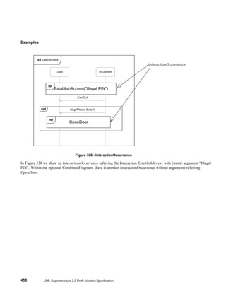


Uml2 super.book.040324
- 1. UML 2.0 Superstructure Specification OMG Specification ptc/04-04-08
- 3. Date: April 2004 Unified Modeling Language: Superstructure version 2.0 Revised Final Adopted Specification ptc/04-04-08
- 5. Copyright © 2001-2003 Adaptive Ltd. Copyright © 2001-2003 Alcatel Copyright © 2001-2003 Borland Software Corporation Copyright © 2001-2003 Computer Associates International, Inc. Copyright © 2001-2003 Telefonaktiebolaget LM Ericsson Copyright © 2001-2003 Fujitsu Copyright © 2001-2003 Hewlett-Packard Company Copyright © 2001-2003 I-Logix Inc. Copyright © 2001-2003 International Business Machines Corporation Copyright © 2001-2003 IONA Technologies Copyright © 2001-2003 Kabira Technologies, Inc. Copyright © 2001-2003 MEGA International Copyright © 2001-2003 Motorola, Inc. Copyright © 1997-2001 Object Management Group. Copyright © 2001-2003 Oracle Corporation Copyright © 2001-2003 SOFTEAM Copyright © 2001-2003 Telelogic AB Copyright © 2001-2003 Unisys Copyright © 2001-2003 X-Change Technologies Group, LLC USE OF SPECIFICATION - TERMS, CONDITIONS & NOTICES The material in this document details an Object Management Group specification in accordance with the terms, conditions and notices set forth below. This document does not represent a commitment to implement any portion of this specification in any company's products. The information contained in this document is subject to change without notice. LICENSES The companies listed above have granted to the Object Management Group, Inc. (OMG) a nonexclusive, royalty-free, paid up, worldwide license to copy and distribute this document and to modify this document and distribute copies of the modified version. Each of the copyright holders listed above has agreed that no person shall be deemed to have infringed the copyright in the included material of any such copyright holder by reason of having used the specification set forth herein or having conformed any computer software to the specification. Subject to all of the terms and conditions below, the owners of the copyright in this specification hereby grant you a fully-paid up, non-exclusive, nontransferable, perpetual, worldwide license (without the right to sublicense), to use this specification to create and distribute software and special purpose specifications that are based upon this specification, and to use, copy, and distribute this specification as provided under the Copyright Act; provided that: (1) both the copyright notice identified above and this permission notice appear on any copies of this specification; (2) the use of the specifications is for informational purposes and will not be copied or posted on any network computer or broadcast in any media and will not be otherwise resold or transferred for commercial purposes; and (3) no modifications are made to this specification. This limited permission automatically terminates without notice if you breach any of these terms or conditions. Upon termination, you will destroy immediately any copies of the specifications in your possession or control. PATENTS The attention of adopters is directed to the possibility that compliance with or adoption of OMG specifications may require use of an invention covered by patent rights. OMG shall not be responsible for identifying patents for which a license may be required by any OMG specification, or for conducting legal inquiries into the legal validity or scope of those patents that are brought to its attention. OMG specifications are prospective and advisory only. Prospective
- 6. users are responsible for protecting themselves against liability for infringement of patents. GENERAL USE RESTRICTIONS Any unauthorized use of this specification may violate copyright laws, trademark laws, and communications regulations and statutes. This document contains information which is protected by copyright. All Rights Reserved. No part of this work covered by copyright herein may be reproduced or used in any form or by any means--graphic, electronic, or mechanical, including photocopying, recording, taping, or information storage and retrieval systems-- without permission of the copyright owner. DISCLAIMER OF WARRANTY WHILE THIS PUBLICATION IS BELIEVED TO BE ACCURATE, IT IS PROVIDED "AS IS" AND MAY CONTAIN ERRORS OR MISPRINTS. THE OBJECT MANAGEMENT GROUP AND THE COMPANIES LISTED ABOVE MAKE NO WARRANTY OF ANY KIND, EXPRESS OR IMPLIED, WITH REGARD TO THIS PUBLICATION, INCLUDING BUT NOT LIMITED TO ANY WARRANTY OF TITLE OR OWNERSHIP, IMPLIED WARRANTY OF MERCHANTABILITY OR WARRANTY OF FITNESS FOR A PARTICULAR PURPOSE OR USE. IN NO EVENT SHALL THE OBJECT MANAGEMENT GROUP OR ANY OF THE COMPANIES LISTED ABOVE BE LIABLE FOR ERRORS CONTAINED HEREIN OR FOR DIRECT, INDIRECT, INCIDENTAL, SPECIAL, CONSEQUENTIAL, RELIANCE OR COVER DAMAGES, INCLUDING LOSS OF PROFITS, REVENUE, DATA OR USE, INCURRED BY ANY USER OR ANY THIRD PARTY IN CONNECTION WITH THE FURNISHING, PERFORMANCE, OR USE OF THIS MATERIAL, EVEN IF ADVISED OF THE POSSIBILITY OF SUCH DAMAGES. The entire risk as to the quality and performance of software developed using this specification is borne by you. This disclaimer of warranty constitutes an essential part of the license granted to you to use this specification. RESTRICTED RIGHTS LEGEND Use, duplication or disclosure by the U.S. Government is subject to the restrictions set forth in subparagraph (c) (1) (ii) of The Rights in Technical Data and Computer Software Clause at DFARS 252.227-7013 or in subparagraph (c)(1) and (2) of the Commercial Computer Software - Restricted Rights clauses at 48 C.F.R. 52.227-19 or as specified in 48 C.F.R. 227-7202-2 of the DoD F.A.R. Supplement and its successors, or as specified in 48 C.F.R. 12.212 of the Federal Acquisition Regulations and its successors, as applicable. The specification copyright owners are as indicated above and may be contacted through the Object Management Group, 250 First Avenue, Needham, MA 02494, U.S.A. TRADEMARKS The OMG Object Management Group Logo®, CORBA®, CORBA Academy®, The Information Brokerage®, XMI® and IIOP® are registered trademarks of the Object Management Group. OMG™, Object Management Group™, CORBA logos™, OMG Interface Definition Language (IDL)™, The Architecture of Choice for a Changing World™, CORBAservices™, CORBAfacilities™, CORBAmed™, CORBAnet™, Integrate 2002™, Middleware That's Everywhere™, UML™, Unified Modeling Language™, The UML Cube logo™, MOF™, CWM™, The CWM Logo™, Model Driven Architecture™, Model Driven Architecture Logos™, MDA™, OMG Model Driven Architecture™, OMG MDA™ and the XMI Logo™ are trademarks of the Object Management Group. All other products or company names mentioned are used for identification purposes only, and may be trademarks of their respective owners.
- 7. COMPLIANCE The copyright holders listed above acknowledge that the Object Management Group (acting itself or through its designees) is and shall at all times be the sole entity that may authorize developers, suppliers and sellers of computer software to use certification marks, trademarks or other special designations to indicate compliance with these materials. Software developed under the terms of this license may claim compliance or conformance with this specification if and only if the software compliance is of a nature fully matching the applicable compliance points as stated in the specification. Software developed only partially matching the applicable compliance points may claim only that the software was based on this specification, but may not claim compliance or conformance with this specification. In the event that testing suites are implemented or approved by Object Management Group, Inc., software developed using this specification may claim compliance or conformance with the specification only if the software satisfactorily completes the testing suites. ISSUE REPORTING All OMG specifications are subject to continuous review and improvement. As part of this process we encourage readers to report any ambiguities, inconsistencies, or inaccuracies they may find by completing the Issue Reporting Form listed on the main web page http://www.omg.org, under Documents & Specifications, Report a Bug/Issue.
- 9. Table of Contents 1 Scope ................................................................................................................................................................ 1 2 Conformance ..................................................................................................................................................... 1 3 Normative references ........................................................................................................................................ 3 4 Terms and definitions ........................................................................................................................................ 3 5 Symbols ............................................................................................................................................................. 4 6 Additional information ........................................................................................................................................ 4 6.1 Changes to Adopted OMG Specifications ............................................................................................ 4 6.2 Architectural Alignment and MDA Support ........................................................................................... 4 6.3 How to Read this Specification ............................................................................................................. 4 6.3.1 Specification format ......................................................................................................... 5 6.4 Acknowledgements............................................................................................................................... 7 Part I - Structure .................................................................................................................................................... 11 7 Classes ............................................................................................................................................................ 13 7.1 Overview............................................................................................................................................. 13 7.2 Kernel – the Root Diagram ................................................................................................................. 15 7.2.1 Comment (from Kernel) ................................................................................................. 16 7.2.2 DirectedRelationship (from Kernel) ............................................................................... 16 7.2.3 Element (from Kernel) ................................................................................................... 17 7.2.4 Relationship (from Kernel) ............................................................................................ 18 7.3 Kernel – the Namespaces Diagram.................................................................................................... 19 7.3.1 ElementImport (from Kernel) ......................................................................................... 19 7.3.2 NamedElement (from Kernel, Dependencies) .............................................................. 21 7.3.3 Namespace (from Kernel) ............................................................................................. 23 7.3.4 PackageableElement (from Kernel) .............................................................................. 25 7.3.5 PackageImport (from Kernel) ........................................................................................ 26 7.3.6 VisibilityKind (from Kernel) ............................................................................................ 27 7.4 Kernel – the Multiplicities Diagram ..................................................................................................... 28 7.4.1 MultiplicityElement (from Kernel) .................................................................................. 28 7.4.2 Type (from Kernel) ........................................................................................................ 31 7.4.3 TypedElement (from Kernel) ......................................................................................... 32 7.5 Kernel – the Expressions Diagram ..................................................................................................... 33 7.5.1 Expression (from Kernel) .............................................................................................. 33 7.5.2 OpaqueExpression (from Kernel) .................................................................................. 34 7.5.3 InstanceValue (from Kernel) ......................................................................................... 35 7.5.4 LiteralBoolean (from Kernel) ......................................................................................... 36 7.5.5 LiteralInteger (from Kernel) ........................................................................................... 37 7.5.6 LiteralNull (from Kernel) ................................................................................................ 37 7.5.7 LiteralSpecification (from Kernel) .................................................................................. 38 7.5.8 LiteralString (from Kernel) ............................................................................................. 39 7.5.9 LiteralUnlimitedNatural (from Kernel) ............................................................................ 39 7.5.10 ValueSpecification (from Kernel) ................................................................................... 40 7.6 Kernel – the Constraints Diagram....................................................................................................... 41 7.6.1 Constraint (from Kernel) ................................................................................................ 42 7.7 Kernel – the Instances Diagram ......................................................................................................... 45 7.7.1 InstanceSpecification (from Kernel) .............................................................................. 45 7.7.2 Slot (from Kernel) .......................................................................................................... 48 7.8 Kernel – the Classifiers Diagram ........................................................................................................ 49 UML Superstructure 2.0 Draft Adopted Specification i
- 10. 7.8.1 Classifier (from Kernel, Dependencies, PowerTypes) ................................................... 49 7.8.2 Generalization (from Kernel, PowerTypes) ................................................................... 54 7.8.3 RedefinableElement (from Kernel) ................................................................................ 58 7.9 Kernel – the Features Diagram........................................................................................................... 59 7.9.1 BehavioralFeature (from Kernel) ................................................................................... 60 7.9.2 Feature (from Kernel) .................................................................................................... 61 7.9.3 Parameter (from Kernel) ............................................................................................... 61 7.9.4 ParameterDirectionKind (from Kernel) .......................................................................... 62 7.9.5 StructuralFeature (from Kernel) .................................................................................... 63 7.10 Kernel – the Operations Diagram ..................................................................................................... 64 7.10.1 Operation (from Kernel) ................................................................................................ 64 7.11 Kernel – the Classes Diagram .......................................................................................................... 68 7.11.1 AggregationKind (from Kernel) ...................................................................................... 68 7.11.2 Association (from Kernel) .............................................................................................. 69 7.11.3 Class (from Kernel) ....................................................................................................... 75 7.11.4 Property (from Kernel, AssociationClasses) .................................................................. 78 7.12 Kernel – the DataTypes Diagram...................................................................................................... 83 7.12.1 DataType (from Kernel) ................................................................................................. 83 7.12.2 Enumeration (from Kernel) ............................................................................................ 85 7.12.3 EnumerationLiteral (from Kernel) .................................................................................. 86 7.12.4 PrimitiveType (from Kernel) .......................................................................................... 86 7.13 Kernel – the Packages Diagram ....................................................................................................... 88 7.13.1 Package (from Kernel) .................................................................................................. 88 7.13.2 PackageMerge (from Kernel) ........................................................................................ 90 7.14 Dependencies ................................................................................................................................... 94 7.14.1 Abstraction (from Dependencies) .................................................................................. 96 7.14.2 Classifier (from Dependencies) ..................................................................................... 96 7.14.3 Dependency (from Dependencies) ............................................................................... 97 7.14.4 NamedElement (from Dependencies) ........................................................................... 98 7.14.5 Permission (from Dependencies) .................................................................................. 98 7.14.6 Realization (from Dependencies) .................................................................................. 99 7.14.7 Substitution (from Dependencies) ............................................................................... 100 7.14.8 Usage (from Dependencies) ....................................................................................... 100 7.15 Interfaces ........................................................................................................................................ 101 7.15.1 BehavioredClassifier (from Interfaces) ........................................................................ 102 7.15.2 Implementation (from Interfaces) ................................................................................ 103 7.15.3 Interface (from Interfaces) ........................................................................................... 103 7.16 AssociationClasses......................................................................................................................... 107 7.16.1 AssociationClass (from AssociationClasses) .............................................................. 108 7.17 PowerTypes .................................................................................................................................... 109 7.17.1 Classifier (from PowerTypes) ...................................................................................... 110 7.17.2 Generalization (from PowerTypes) ............................................................................. 110 7.17.3 GeneralizationSet (from PowerTypes) ........................................................................ 110 7.18 Diagrams......................................................................................................................................... 118 8 Components .................................................................................................................................................. 123 8.1 Overview ........................................................................................................................................... 123 8.2 Abstract syntax ................................................................................................................................. 124 8.3 Class Descriptions ............................................................................................................................ 126 8.3.1 Component .................................................................................................................. 126 8.3.2 Connector (from InternalStructures, as specialized) ................................................... 135 8.3.3 Realization (from Dependencies, as specialized) ....................................................... 138 ii UML Superstructure 2.0 Draft Adopted Specification
- 11. 8.4 Diagrams .......................................................................................................................................... 139 9 Composite Structures .................................................................................................................................... 143 9.1 Overview........................................................................................................................................... 143 9.2 Abstract syntax ................................................................................................................................. 143 9.3 Class Descriptions ............................................................................................................................ 148 9.3.1 Class (from StructuredClasses, as specialized) .......................................................... 148 9.3.2 Classifier (from Collaborations, as specialized) .......................................................... 149 9.3.3 Collaboration (from Collaborations) ............................................................................ 150 9.3.4 CollaborationOccurrence (from Collaborations) .......................................................... 152 9.3.5 ConnectableElement (from InternalStructures) ........................................................... 156 9.3.6 Connector (from InternalStructures) ............................................................................ 156 9.3.7 ConnectorEnd (from InternalStructures, Ports) ........................................................... 158 9.3.8 EncapsulatedClassifier (from Ports) ............................................................................ 159 9.3.9 InvocationAction (from Actions, as specialized) .......................................................... 160 9.3.10 Parameter (Collaboration, as specialized) .................................................................. 160 9.3.11 Port (from Ports) .......................................................................................................... 160 9.3.12 Property (from InternalStructures, as specialized) ...................................................... 164 9.3.13 StructuredClassifier (from InternalStructures) ............................................................. 166 9.3.14 Trigger (from InvocationActions, as specialized) ........................................................ 170 9.3.15 Variable (from StructuredActivities, as specialized) .................................................... 171 9.4 Diagrams .......................................................................................................................................... 171 10 Deployments ................................................................................................................................................. 173 10.1 Overview......................................................................................................................................... 173 10.2 Abstract syntax ............................................................................................................................... 173 10.3 Class Descriptions .......................................................................................................................... 176 10.3.1 Artifact ......................................................................................................................... 176 10.7.1 CommunicationPath .................................................................................................... 178 10.7.2 DeployedArtifact .......................................................................................................... 179 10.7.3 Deployment ................................................................................................................. 180 10.11.1 DeploymentTarget ....................................................................................................... 181 10.12.1 DeploymentSpecification ............................................................................................. 182 10.14.1 Device ......................................................................................................................... 184 10.14.2 ExecutionEnvironment ................................................................................................ 186 10.14.3 InstanceSpecification (from Kernel, as specialized) .................................................... 187 10.14.4 Manifestation ............................................................................................................... 188 10.14.5 Node ............................................................................................................................ 188 10.15.1 Property (from InternalStructures, as specialized) ...................................................... 190 10.16 Diagrams ...................................................................................................................................... 191 10.17 Graphical paths............................................................................................................................. 193 Part II - Behavior ................................................................................................................................................. 195 11 Actions ........................................................................................................................................................... 197 11.1 Overview......................................................................................................................................... 197 11.2 Abstract Syntax............................................................................................................................... 199 11.3 Class Descriptions .......................................................................................................................... 211 11.3.1 AcceptCallAction ......................................................................................................... 211 11.3.2 AcceptEventAction ...................................................................................................... 212 11.3.3 AddStructuralFeatureValueAction ............................................................................... 214 11.3.4 AddVariableValueAction ............................................................................................. 216 11.3.5 ApplyFunctionAction ................................................................................................... 217 11.3.6 BroadcastSignalAction ................................................................................................ 218 11.3.7 CallAction .................................................................................................................... 219 UML Superstructure 2.0 Draft Adopted Specification iii
- 12. 11.3.8 CallBehaviorAction ...................................................................................................... 220 11.3.9 CallOperationAction .................................................................................................... 222 11.3.10 ClearAssociationAction ............................................................................................... 224 11.3.11 ClearStructuralFeatureAction ...................................................................................... 225 11.3.12 ClearVariableAction .................................................................................................... 226 11.3.13 CreateLinkAction ......................................................................................................... 227 11.3.14 CreateLinkObjectAction .............................................................................................. 228 11.3.15 CreateObjectAction ..................................................................................................... 229 11.3.16 DestroyLinkAction ....................................................................................................... 230 11.3.17 DestroyObjectAction ................................................................................................... 231 11.3.18 InvocationAction .......................................................................................................... 232 11.3.19 LinkAction .................................................................................................................... 232 11.3.20 LinkEndCreationData .................................................................................................. 234 11.3.21 LinkEndData ................................................................................................................ 235 11.3.22 MultiplicityElement (as specialized) ............................................................................ 236 11.3.23 PrimitiveFunction ......................................................................................................... 236 11.3.24 QualifierValue .............................................................................................................. 237 11.3.25 RaiseExceptionAction ................................................................................................. 238 11.3.26 ReadExtentAction ....................................................................................................... 239 11.3.27 ReadIsClassifiedObjectAction ..................................................................................... 240 11.3.28 ReadLinkAction ........................................................................................................... 241 11.3.29 ReadLinkObjectEndAction .......................................................................................... 242 11.3.30 ReadLinkObjectEndQualifierAction ............................................................................. 243 11.3.31 ReadSelfAction ........................................................................................................... 244 11.3.32 ReadStructuralFeatureAction ...................................................................................... 246 11.3.33 ReadVariableAction .................................................................................................... 246 11.3.34 ReclassifyObjectAction ............................................................................................... 247 11.3.35 RemoveStructuralFeatureValueAction ........................................................................ 248 11.3.36 RemoveVariableValueAction ...................................................................................... 249 11.3.37 ReplyAction ................................................................................................................. 250 11.3.38 SendObjectAction ....................................................................................................... 251 11.3.39 SendSignalAction ........................................................................................................ 252 11.3.40 StartOwnedBehaviorAction ......................................................................................... 253 11.3.41 StructuralFeatureAction .............................................................................................. 254 11.3.42 TestIdentityAction ........................................................................................................ 255 11.3.43 VariableAction ............................................................................................................. 256 11.3.44 WriteStructuralFeatureAction ...................................................................................... 257 11.3.45 WriteLinkAction ........................................................................................................... 258 11.3.46 WriteVariableAction ..................................................................................................... 258 11.4 Diagrams......................................................................................................................................... 259 12 Activities ........................................................................................................................................................ 261 12.1 Overview ......................................................................................................................................... 261 12.2 Abstract Syntax............................................................................................................................... 262 12.3 Class Descriptions .......................................................................................................................... 277 12.3.1 Action .......................................................................................................................... 277 12.3.2 Activity ......................................................................................................................... 281 12.3.3 ActivityEdge ................................................................................................................ 291 12.3.4 ActivityFinalNode ........................................................................................................ 296 12.3.5 ActivityGroup ............................................................................................................... 299 12.3.6 ActivityNode ................................................................................................................ 300 12.3.7 ActivityParameterNode ............................................................................................... 302 iv UML Superstructure 2.0 Draft Adopted Specification
- 13. 12.3.8 ActivityPartition ............................................................................................................ 305 12.3.9 CentralBufferNode ...................................................................................................... 310 12.3.10 Clause ......................................................................................................................... 312 12.3.11 ConditionalNode .......................................................................................................... 312 12.3.12 ControlFlow ................................................................................................................. 314 12.3.13 ControlNode ................................................................................................................ 315 12.3.14 DataStoreNode ........................................................................................................... 317 12.3.15 DecisionNode .............................................................................................................. 318 12.3.16 ExceptionHandler ........................................................................................................ 321 12.3.17 ExecutableNode .......................................................................................................... 324 12.3.18 ExpansionKind ............................................................................................................ 324 12.3.19 ExpansionNode ........................................................................................................... 324 12.3.20 ExpansionRegion ........................................................................................................ 325 12.3.21 FinalNode .................................................................................................................... 331 12.3.22 FlowFinalNode ............................................................................................................ 333 12.3.23 ForkNode .................................................................................................................... 334 12.3.24 InitialNode ................................................................................................................... 335 12.3.25 InputPin ....................................................................................................................... 337 12.3.26 InterruptibleActivityRegion .......................................................................................... 337 12.3.27 JoinNode ..................................................................................................................... 339 12.3.28 LoopNode .................................................................................................................... 342 12.3.29 MergeNode ................................................................................................................. 344 12.3.30 ObjectFlow .................................................................................................................. 345 12.3.31 ObjectNode ................................................................................................................. 350 12.3.32 ObjectNodeOrderingKind ............................................................................................ 353 12.3.33 OutputPin .................................................................................................................... 353 12.3.34 Parameter (as specialized) ......................................................................................... 353 12.3.35 ParameterEffectKind ................................................................................................... 355 12.3.36 ParameterSet .............................................................................................................. 356 12.3.37 Pin ............................................................................................................................... 358 12.3.38 StructuredActivityNode ................................................................................................ 365 12.3.39 ValuePin ...................................................................................................................... 366 12.3.40 Variable ....................................................................................................................... 367 12.4 Diagrams ........................................................................................................................................ 368 13 Common Behaviors ....................................................................................................................................... 373 13.1 Overview......................................................................................................................................... 373 13.2 Abstract syntax ............................................................................................................................... 378 13.3 Class Descriptions .......................................................................................................................... 382 13.3.1 Activity (from BasicBehaviors) .................................................................................... 382 13.3.2 AnyTrigger (from Communications) ............................................................................ 383 13.3.3 Behavior (from BasicBehaviors) .................................................................................. 383 13.3.4 BehavioralFeature (from BasicBehaviors, Communications, specialized) .................. 386 13.3.5 BehavioredClassifier (from BasicBehaviors) ............................................................... 387 13.3.6 CallConcurrencyKind (from Communications) ............................................................ 388 13.3.7 CallTrigger (from Communications) ............................................................................ 389 13.3.8 ChangeTrigger (from Communications) ...................................................................... 389 13.3.9 Class (from Communications, specialized) ................................................................. 390 13.3.10 Duration (from SimpleTime) ........................................................................................ 391 13.3.11 DurationConstraint (from SimpleTime) ........................................................................ 392 13.3.12 DurationInterval (from SimpleTime) ............................................................................ 393 13.3.13 DurationObservationAction (from SimpleTime) ........................................................... 394 UML Superstructure 2.0 Draft Adopted Specification v
- 14. 13.3.14 Interface (from Communications, specialized) ............................................................ 395 13.3.15 Interval (from SimpleTime) .......................................................................................... 395 13.3.16 IntervalConstraint (from SimpleTime) .......................................................................... 396 13.3.17 MessageTrigger (from Communications) .................................................................... 396 13.3.18 OpaqueExpression (from BasicBehaviors, specialized) .............................................. 397 13.3.19 Operation (from Communications, as specialized) ...................................................... 397 13.3.20 Reception (from Communications) .............................................................................. 398 13.3.21 Signal (from Communications) .................................................................................... 399 13.3.22 SignalTrigger (from Communications) ......................................................................... 400 13.3.23 TimeConstraint (from SimpleTime) ............................................................................. 401 13.3.24 TimeExpression (from SimpleTime) ............................................................................ 402 13.3.25 TimeInterval (from SimpleTime) .................................................................................. 402 13.3.26 TimeObservationAction (from SimpleTime) ................................................................ 403 13.3.27 TimeTrigger (from Communications) ........................................................................... 404 13.3.28 Trigger (from Communications) .................................................................................. 405 14 Interactions .................................................................................................................................................... 407 14.1 Overview ......................................................................................................................................... 407 14.2 Abstract syntax ............................................................................................................................... 408 14.3 Class Descriptions .......................................................................................................................... 414 14.3.1 CombinedFragment (from Fragments) ........................................................................ 414 14.3.2 Continuation (from Fragments) ................................................................................... 419 14.3.3 EventOccurrence (from BasicInteractions) ................................................................. 421 14.3.4 ExecutionOccurrence (from BasicInteractions) ........................................................... 422 14.3.5 Gate (from Fragments) ................................................................................................ 423 14.3.6 GeneralOrdering (from BasicInteractions) .................................................................. 424 14.3.7 Interaction (from BasicInteraction, Fragments) ........................................................... 424 14.3.8 InteractionConstraint (from Fragments) ...................................................................... 427 14.3.9 InteractionFragment (from Fragments) ....................................................................... 428 14.3.10 InteractionOccurrence (from Fragments) .................................................................... 428 14.3.11 InteractionOperand (from Fragments) ......................................................................... 431 14.3.12 InteractionOperator (from Fragments) ........................................................................ 432 14.3.13 Lifeline (from BasicInteractions, Fragments) ............................................................... 433 14.3.14 Message (from BasicInteractions) ............................................................................... 434 14.3.15 MessageEnd (from BasicInteractions) ........................................................................ 437 14.3.16 PartDecomposition (from Fragments) ......................................................................... 437 14.3.17 StateInvariant (from BasicInteractions) ....................................................................... 440 14.3.18 Stop (from BasicInteractions) ...................................................................................... 441 14.4 Diagrams......................................................................................................................................... 442 15 State Machines .............................................................................................................................................. 463 15.1 Overview ......................................................................................................................................... 463 15.2 Abstract Syntax............................................................................................................................... 464 15.3 Class Descriptions .......................................................................................................................... 467 15.3.1 ConnectionPointReference (from BehaviorStatemachines) ........................................ 467 15.3.2 Interface (from ProtocolStatemachines, as specialized) ............................................. 470 15.3.3 FinalState (from BehaviorStatemachines) .................................................................. 470 15.3.4 Port ( (from ProtocolStatemachines, as specialized) .................................................. 471 15.3.5 ProtocolConformance (from ProtocolStatemachines) ................................................. 471 15.3.6 ProtocolStateMachine (from ProtocolStatemachines) ................................................. 472 15.3.7 ProtocolTransition (from ProtocolStateMachines) ....................................................... 474 15.3.8 PseudoState (from BehaviorStatemachines) .............................................................. 478 15.3.9 PseudoStateKind (from BehaviorStatemachines) ....................................................... 483 vi UML Superstructure 2.0 Draft Adopted Specification
- 15. 15.3.10 Region (from BehaviorStatemachines) ....................................................................... 484 15.3.11 State (from BehaviorStatemachines) .......................................................................... 486 15.3.12 StateMachine (from BehaviorStatemachines) ............................................................. 498 15.3.13 TimeTrigger ( from BehaviorStatemachines, as specialized) ...................................... 507 15.3.14 Transition (from BehaviorStatemachines) ................................................................... 507 15.3.15 Vertex (from BehaviorStatemachines) ........................................................................ 515 15.3.16 TransitionKind ............................................................................................................. 515 15.4 Diagrams ........................................................................................................................................ 516 16 Use Cases ..................................................................................................................................................... 521 16.1 Overview......................................................................................................................................... 521 16.2 Abstract syntax ............................................................................................................................... 521 16.3 Class Descriptions .......................................................................................................................... 522 16.3.1 Actor (from UseCases) ................................................................................................ 522 16.3.2 Classifier (from UseCases, as specialized) ................................................................. 524 16.3.3 Extend (from UseCases) ............................................................................................. 525 16.3.4 ExtensionPoint (from UseCases) ................................................................................ 527 16.3.5 Include (from UseCases) ............................................................................................ 528 16.3.6 UseCase (from UseCases) ......................................................................................... 530 16.4 Diagrams ........................................................................................................................................ 535 Part III - Supplement ........................................................................................................................................... 541 17 Auxiliary Constructs ....................................................................................................................................... 543 17.1 Overview......................................................................................................................................... 543 17.2 InformationFlows ............................................................................................................................ 543 17.2.1 InformationFlow (from InformationFlows) .................................................................... 544 17.2.2 InformationItem (from InformationFlows) .................................................................... 545 17.3 Models ............................................................................................................................................ 547 17.3.1 Model (from Models) ................................................................................................... 547 17.4 PrimitiveTypes ................................................................................................................................ 549 17.4.1 Boolean (from PrimitiveTypes) .................................................................................... 550 17.4.2 Integer (from PrimitiveTypes) ...................................................................................... 551 17.4.3 String (from PrimitiveTypes) ........................................................................................ 552 17.4.4 UnlimitedNatural (from PrimitiveTypes) ...................................................................... 553 17.5 Templates ....................................................................................................................................... 554 17.5.1 ParameterableElement ............................................................................................... 556 17.5.2 TemplateableElement ................................................................................................. 558 17.5.3 TemplateBinding ......................................................................................................... 560 17.5.4 TemplateParameter .................................................................................................... 561 17.5.5 TemplateParameterSubstitution .................................................................................. 562 17.5.6 TemplateSignature ...................................................................................................... 563 17.5.7 Classifier (as specialized) ........................................................................................... 565 17.5.8 ClassifierTemplateParameter ...................................................................................... 570 17.5.9 RedefinableTemplateSignature ................................................................................... 571 17.5.10 Package (as specialized) ............................................................................................ 572 17.5.11 NamedElement (as specialized) ................................................................................. 574 17.5.12 Operation (as specialized) .......................................................................................... 577 17.5.13 Operation (as specialized) .......................................................................................... 577 17.5.14 OperationTemplateParameter ..................................................................................... 578 17.5.15 ConnectableElement (as specialized) ......................................................................... 579 17.5.16 ConnectableElementTemplateParameter ................................................................... 580 17.5.17 Property (as specialized) ............................................................................................. 581 17.5.18 ValueSpecification (as specialized) ............................................................................. 582 UML Superstructure 2.0 Draft Adopted Specification vii
- 16. 18 Profiles ........................................................................................................................................................... 583 18.1 Overview ......................................................................................................................................... 583 18.1.1 Positioning profiles versus metamodels, MOF and UML ............................................ 583 18.1.2 Profiles History and design requirements ................................................................... 583 18.2 Abstract syntax ............................................................................................................................... 585 18.3 Class descriptions........................................................................................................................... 586 18.3.1 Extension (from Profiles) ............................................................................................. 586 18.3.2 ExtensionEnd (from Profiles) ...................................................................................... 588 18.3.3 Class (from Constructs, Profiles) ................................................................................ 589 18.3.4 Package (from Constructs, Profiles) ........................................................................... 590 18.3.5 Profile (from Profiles) .................................................................................................. 591 18.3.6 ProfileApplication (from Profiles) ................................................................................. 594 18.3.7 Stereotype (from Profiles) ........................................................................................... 596 18.4 Diagrams......................................................................................................................................... 599 Part IV - Appendices ........................................................................................................................................... 601 Appendix A. Diagrams ......................................................................................................................................... 603 Appendix B. Standard Stereotypes ...................................................................................................................... 609 B.1 Basic................................................................................................................................................. 609 B.2 Intermediate...................................................................................................................................... 613 B.3 Complete .......................................................................................................................................... 614 Appendix C. Component Profile Examples ......................................................................................................... 617 C.1 J2EE/EJB Component Profile Example ........................................................................................... 617 C.2 COM Component Profile Example ................................................................................................... 618 C.3 .NET Component Profile Example ................................................................................................... 618 C.4 CCM Component Profile Example ................................................................................................... 619 Appendix D. Tabular Notations ........................................................................................................................... 621 D.1 Tabular Notation for Sequence Diagrams ........................................................................................ 621 D.2 Tabular Notation for Other Behavioral Diagrams ............................................................................. 623 Appendix E. Classifiers Taxonomy ..................................................................................................................... 625 Appendix F. XMI Serialization and Schema......................................................................................................... 627 Index .................................................................................................................................................................... 629 viii UML Superstructure 2.0 Draft Adopted Specification
- 17. 1 Scope This UML 2.0: Superstructure is the second of two complementary specifications that represent a major revision to the Object Management Group’s Unified Modeling Language (UML), for which the most current version is UML v1.4. The first specification, which serves as the architectural foundation for this specification, is the UML 2.0: Infrastructure. This UML 2.0: Superstructure defines the user level constructs required for UML 2.0. It is complemented by UML 2.0: Infrastructure which defines the foundational language constructs required for UML 2.0. The two complementary specifications constitute a complete specification for the UML 2.0 modeling language. Issue 6211 - removed editorial comment with instructions to the FTF 2 Conformance Issue 6211 - removed editorial comment with instructions to the FTF The basic units of compliance for UML are the packages which define the UML metamodel. Unless otherwise qualified, complying with a package requires complying with its abstract syntax, well-formedness rules, semantics, notation and XMI schema. Complying with a particular package requires complying with any packages on which the particular package depends via a package merge or import relationship In the case of the UML Superstructure, the metamodel is organized into medium-grain packages (compare the InfrastructureLibrary’s fine-grained packages) that support flexible compliance points. All UML 2.0 compliant implementations are required to implement the UML::Classes::Kernel package. All other UML Superstructure packages are optional compliance points. The following table summarizes the compliance points of the UML 2.0: Superstructure, where the following compliance options are valid: • no compliance: Implementation does not comply with the abstract syntax, well-formedness rules, semantics and nota- tion of the package. • partial compliance: Implementation partially complies with the abstract syntax, well-formedness rules, semantics and notation of the package. • compliant compliance: Implementation fully complies with the abstract syntax, well-formedness rules, semantics and notation of the package • interchange compliance: Implementation fully complies with the abstract syntax, well-formedness rules, semantics, notation and XMI schema of the package. Table 1 Summary of Compliance Points Compliance Level Compliance Point Valid Options Basic (Level 1) Classes::Kernel complete, interchange Basic (Level 1) Activities::BasicActivities no, partial, complete, interchange UML Superstructure 2.0 Draft Adopted Specification 1
- 18. Table 1 Summary of Compliance Points Basic (Level 1) AuxiliaryConstructs::Primitives no, partial, complete, interchange Basic (Level 1) Classes::Dependencies no, partial, complete, interchange Basic (Level 1) Classes::Interfaces no, partial, complete, interchange Basic (Level 1) CommonBehaviors:: no, partial, complete, interchange BasicBehaviors Basic (Level 1) CompositeStructures:: no, partial, complete, interchange InternalStructures Basic (Level 1) Interactions::BasicInteractions no, partial, complete, interchange Basic (Level 1) AuxiliaryConstructs:: no, partial, complete, interchange PrimitiveTypes Basic (Level 1) UseCases no, partial, complete, interchange Intermediate (Level 2) Actions::IntermediateActions no, partial, complete, interchange Intermediate (Level 2) Activities:: no, partial, complete, interchange IntermediateActivities Intermediate (Level 2) Activities:: no, partial, complete, interchange StructuredActivities Intermediate (Level 2) CommonBehaviors:: no, partial, complete, interchange Communications Intermediate (Level 2) CommonBehaviors::Time no, partial, complete, interchange Intermediate (Level 2) Components::BasicComponents no, partial, complete, interchange Intermediate (Level 2) CompositeStructures::Actions no, partial, complete, interchange Intermediate (Level 2) CompositeStructures::Ports no, partial, complete, interchange Intermediate (Level 2) CompositeStructures:: no, partial, complete, interchange StructuredClasses Intermediate (Level 2) Deployments::Artifacts no, partial, complete, interchange Intermediate (Level 2) Deployments::Nodes no, partial, complete, interchange Intermediate (Level 2) Interactions::Fragments no, partial, complete, interchange Intermediate (Level 2) Profiles no, partial, complete, interchange Intermediate (Level 2) StateMachines:: no, partial, complete, interchange BehaviorStateMachines Intermediate (Level 2) StateMachines:: no, partial, complete, interchange MaximumOneRegion Complete (Level 3) Actions::CompleteActions no, partial, complete, interchange Complete (Level 3) Activities::CompleteActivities no, partial, complete, interchange Complete (Level 3) Activities:: no, partial, complete, interchange CompleteStructuredActivities 2 UML Superstructure 2.0 Draft Adopted Specification
- 19. Table 1 Summary of Compliance Points Complete (Level 3) Activities:: no, partial, complete, interchange ExtraStructuredActivities Complete (Level 3) AuxiliaryConstructs:: no, partial, complete, interchange InformationFlows Complete (Level 3) AuxiliaryConstructs:: no, partial, complete, interchange Models Complete (Level 3) AuxiliaryConstructs::Templates no, partial, complete, interchange Complete (Level 3) Classes:: no, partial, complete, interchange AssociationClasses Complete (Level 3) Classes:: no, partial, complete, interchange PowerTypes Complete (Level 3) CompositeStructures:: no, partial, complete, interchange Collaborations Complete (Level 3) Components:: no, partial, complete, interchange PackagingComponents Complete (Level 3) Deployments:: no, partial, complete, interchange ComponentDeployments Complete (Level 3) StateMachines::ProtocolStateMachines no, partial, complete, interchange 3 Normative references The following normative documents contain provisions which, through reference in this text, constitute provisions of this specification. For dated references, subsequent amendments to, or revisions of, any of these publications do not apply. • UML 2.0 Superstructure RFP • UML 2. Infrastructure Specification • MOF 2.0 Specification Issue 6211 - removed editorial comment with instructions to the FTF 4 Terms and definitions Issue 6211 - removed editorial comment with instructions to the FTF, added first paragraph, and removed the glossary from this point in the document There are no formal definitions in this specification that are taken from other documents. UML Superstructure 2.0 Draft Adopted Specification 3
- 20. 5 Symbols Issue 6211 - removed editorial comment with instructions to the FTF and added the first paragraph. There are no symbols defined in this specification. 6 Additional information 6.1 Changes to Adopted OMG Specifications This specification, in conjunction with the specification that complements it, the UML 2.0: Infrastructure, completely replaces the UML 1.4.1 and UML 1.5 with Action Semantics specifications, except for the “Model Interchange Using CORBA IDL” (see Chapter 5, Section 5.3 of the OMG UML Specification v1.4, OMG document ad/01-02-17). It is recommended that “Model Interchange Using CORBA IDL” is retired as an adopted technology because of lack of vendor and user interest. 6.2 Architectural Alignment and MDA Support Chapter 1, “Language Architecture” of the UML 2.0: Infrastructure explains how the UML 2.0: Infrastructure is architecturally aligned with the UML 2.0: Superstructure that complements it. It also explains how the InfrastructureLibrary defined in the UML 2.0: Infrastructure can be strictly reused by MOF 2.0 specifications. It is the intent that the unified MOF 2.0 Core specification must be architecturally aligned with the UML 2.0: Infrastructure part of this specification. Similarly, the unified UML 2.0 Diagram Interchange specification must be architecturally aligned with the UML 2.0: Superstructure part of this specification. The OMG’s Model Driven Architecture (MDA) initiative is an evolving conceptual architecture for a set of industry-wide technology specifications that will support a model-driven approach to software development. Although MDA is not itself a technology specification, it represents an important approach and a plan to achieve a cohesive set of model-driven technology specifications. This specification’s support for MDA is discussed in the UML 2.0: Infrastructure Appendix B, “Support for Model Driven Architecture”. 6.3 How to Read this Specification The rest of this document contains the technical content of this specification. As background for this specification, readers are encouraged to first read the UML: Infrastructure specification that complements this. Part I, “Introduction” of UML: Infrastructure explains the language architecture structure and the formal approach used for its specification. Afterwards the reader may choose to either explore the InfrastructureLibrary, described in Part II, “Infrastructure Library”, or the Classes::Kernel package which reuses it, described in Chapter 1, “Classes”. The former specifies the flexible metamodel library that is reused by the latter; the latter defines the basic constructs used to define the UML metamodel. With that background the reader should be well prepared to explore the user level constructs defined in this UML: Superstructure specification. These concepts are organized into three parts: Part I - “Structure”, Part II - “Behavior”, and Part III - “Supplement”. Part I - “Structure” defines the static, structural constructs (e.g., classes, components, nodes artifacts) used in various structural diagrams, such as class diagrams, component diagrams and deployment diagrams. Part II - “Behavior” specifies the dynamic, behavioral constructs (e.g., activities, interactions, state machines) used in various behavioral diagrams, such as activity diagrams, sequence diagrams, and state machine diagrams. Part I - “Structure” defines auxiliary constructs (e.g., information flows, models, templates, primitive types) and the profiles used to customize UML for various domains, 4 UML Superstructure 2.0 Draft Adopted Specification
- 21. platforms and methods. Although the chapters are organized in a logical manner and can be read sequentially, this is a reference specification is intended to be read in a non-sequential manner. Consequently, extensive cross-references are provided to facilitate browsing and search. Issue 7156 - add explanatiuon of chapter structures 6.3.1 Specification format The concepts of UML are grouped into three major parts: • Part I: Concepts related to the modeling of structure • Part II: Concepts related to the modeling of behavior • Part III: Supplementary concepts Within each part, the concepts are grouped into chapters according to modeling capability. A capability typically covers a specific modeling formalism. For instance, all concepts related to the state machine modeling capability are gathered in the state machines chapter and all concepts related to the activities modeling capability are in the activities chapter. The capability chapters in each part are presented in alphabetical order. Within each chapter, there is first a brief informal description of the capability described in that chapter. This is followed by a section describing the abstract syntax for that capability. The abstract syntax is defined by a MOF model (i.e., the UML metamodel) with each modeling concept represented by an instance of a MOF class or association. The model is decomposed into packages according to capabilities. In the specification, this model is described by a set of UML class and package diagrams showing the concepts and their relationships. The diagrams were designed to provide comprehensive information about a related set of concepts, but it should be noted that, in many cases, the representation of a concept in a given diagram displays only a subset of its features (the subset that is relevant in that context). The same concept may appear in multiple diagrams with different feature subsets. For a complete specification of the features of a concept, readers should refer to its formal concept description (explained below). When the concepts in the capability are grouped into sub-packages, the diagrams are also grouped accordingly with a heading identifying the sub-package preceding each group of diagrams. In addition, the name of the owning package is included in each figure caption. The “Concept Definitions” section follows the abstract syntax section. This section includes formal specifications of all concepts belonging to that capability, listed in alphabetical order. Each concept is described separately according to the format explained below. The final section in most chapters gives an overview of the diagrams, diagram elements, and notational rules and conventions that are specific to that capability. The formal concept descriptions of individual concepts are broken down into sub-sections corresponding to different aspects. In cases where a given aspect does not apply, its sub-section may be omitted entirely from the class description. The following sub-sections and conventions are used to specify a concept: • The heading gives the formal name of the concept and may indicate, in parentheses, the sub-package in which the con- cept is defined. If no sub-package is provided, then the concept is defined in the top-level package for that capability. In some cases, there may be more than one sub-package name listed. This occurs when a concept is defined in multiple package merge increments – one per package. • In some cases, following the heading is a brief, one- or two-sentence informal description of the meaning of a concept. This is intended as a quick reference for those who want only the basic information about a concept. • All the direct generalizations of a concept are listed, alphabetically, in the “Generalizations” sub-section. A “direct” UML Superstructure 2.0 Draft Adopted Specification 5
- 22. generalization of a concept is a concept (e.g., a class) that is immediately above it in the hierarchy of its ancestors (i.e., its “parent”). Note that these items are hyperlinked in electronic versions of the document to facilitate navigation through the metamodel class hierarchy. Readers of hardcopy versions can use the page numbers listed with the names to rapidly locate the description of the superclass. This sub-section is omitted for enumerations. • A more detailed description of the purpose, nature, and potential usage of the concept may be provided in the “Descrip- tion” sub-section. This too is informal. If a concept is defined in multiple increments, then the first part of the descrip- tion covers the top-level package and is followed, in turn, by successive description increments for each sub-package. The individual increments are identified by a sub-package heading such as Package PowerTypes This indicates that the text that follows the heading describes the increment that was added in the PowerTypes sub- package. The description continues either until the end of the sub-section or until the next sub-package increment heading is encountered. This convention for describing sub-package increments is applied to all other sub-sections related to the concept. • The “Attributes” sub-section of a concept description lists each of the attributes that are defined for that metaclass. Each attribute is specified by its formal name, its type, and multiplicity. If no multiplicity is listed, it defaults to 0..*. This is followed by a textual description of the purpose and meaning of the attribute. If an attribute is derived, the name will be preceded by a slash. For example: • body: String[1] Specifies a string that is the comment specifies an attribute called “body” whose type is “String” and whose multiplicity is 1. If an attribute is derived, where possible, the definition will also include a specification (usually expressed as an OCL constraint) specifying how that attribute is derived. For instance: • /isComposite : Boolean A state with isComposite = true is said to be a composite state. A composite state is a state that contains at least one region> isComposite = (region > 1) • The “Associations” sub-section lists all the association ends owned by the concept. The format for these is the same as the one for attributes described above. Association ends that are specializations or redefinitions of other association ends in superclasses are flagged appropriately. For example: For example: • lowerValue: ValueSpecification[0..1] {subsets Element::ownedElement}The specification of the lower bound for this multiplicity. specifies an association end called “lowerValue” that is connected to the “ValueSpecification” class and whose multi- plicity is 0..1. Furthermore, it is a specialization of the “ownedElement” association end of the class “Element”. As with derived attributes, if an association end is derived, where possible, the definition will also include a specifica- tion (usually expressed as an OCL constraint) specifying how that association end is derived. • The “Constraints” sub-section contains a numerical list of all the constraints that define additional well-formedness rules that apply to this concept. Each constraint consists of a textual description and may be followed by a formal con- straint expressed in OCL. Note that in a few cases, it may not be possible to express the constraint in OCL, in which case the formal expression is omitted. 6 UML Superstructure 2.0 Draft Adopted Specification
- 23. • “Additional Operations” contains a numerical list of operations that are applicable to the concept. These may be queries or utility operations that are used to define constraints or other operations. Where possible, operations are specified using OCL. • The “Semantics” sub-section describes the meaning of the concept in terms of its concrete manifestation. This is a specification of the set of things that the concept models (represents) including, where appropriate, a description of the behavior of those things (i.e., the dynamic semantics of the concept). • “Semantic Variation Points” explicitly identifies the areas where the semantics are intentionally underspecified to pro- vide leeway for domain-specific refinements of the general UML semantics (e.g., by using stereotypes and profiles). • The “Notation” sub-section gives the basic notational forms used to represent a concept and its features in diagrams. Only concepts that can appear in diagrams will have a notation specified. This typically includes a simple example illustrating the basic notation. • The “Presentation Options” sub-section supplements the “Notation” section by providing alternative representations for the concept or its parts. Users have the choice to use either the forms described in this sub-section or the forms described in the “Notation” sub-section. • “Style Guidelines” identifies notational conventions recommended by the specification. These are not normative but, if applied consistently, will facilitate communication and understanding. For example, there is a style guideline that sug- gests that the names of classes should be capitalized and another one that recommends that the names of abstract classes be written out in italic font. (Note that these specific recommendations only make sense in certain writing sys- tems, which is why they cannot be normative.) • The “Examples” sub-section, if present, includes additional illustrations of the application of the concept and its nota- tion. • “Changes from previous UML” identifies the main differences in the specification of the concept relative to UML ver- sions 1.5 and earlier. 6.4 Acknowledgements The following companies submitted and/or supported parts of this specification: • Adaptive • Advanced Concepts Center LLC • Alcatel • Artisan • Borland • Ceira Technologies • Commissariat à L'Energie Atomique • Computer Associates • Compuware • DaimlerChrysler • Domain Architects • Embarcadero Technologies UML Superstructure 2.0 Draft Adopted Specification 7
- 24. • Enea Business Software • Ericsson • France Telecom • Fraunhofer FOKUS • Fujitsu • Gentleware • Intellicorp • Hewlett-Packard • I-Logix • International Business Machines • IONA • Jaczone • Kabira Technologies • Kennedy Carter • Klasse Objecten • KLOCwork • Lockheed Martin • MEGA International • Mercury Computer • Motorola • MSC.Software • Northeastern University • Oracle • Popkin Software • Proforma • Project Technology • Sims Associates • SOFTEAM • Sun Microsystems • Syntropy Ltd. • Telelogic 8 UML Superstructure 2.0 Draft Adopted Specification
- 25. • Thales Group • TNI-Valiosys • Unisys • University of Kaiserslautern • University of Kent • VERIMAG • WebGain • X-Change Technologies • 7irene • 88solutions The following persons were members of the core team that designed and wrote this specification: Don Baisley, Morgan Björkander, Conrad Bock, Steve Cook, Philippe Desfray, Nathan Dykman, Anders Ek, David Frankel, Eran Gery, Øystein Haugen, Sridhar Iyengar, Cris Kobryn, Birger Møller-Pedersen, James Odell, Gunnar Övergaard, Karin Palmkvist, Guus Ramackers, Jim Rumbaugh, Bran Selic, Thomas Weigert and Larry Williams. In addition, the following persons contributed valuable ideas and feedback that significantly improved the content and the quality of this specification: Colin Atkinson, Ken Baclawski, Mariano Belaunde, Steve Brodsky, Roger Burkhart, Bruce Douglass, Karl Frank, William Frank, Sandy Friedenthal, Sébastien Gerard, Dwayne Hardy, Mario Jeckle, Larry Johnson, Allan Kennedy, Mitch Kokar, Thomas Kuehne, Michael Latta, Antoine Lonjon, Nikolai Mansurov, Dave Mellor, Stephen Mellor, Joaquin Miller, Jeff Mischkinksky, Hiroshi Miyazaki, Jishnu Mukerji, Ileana Ober, Barbara Price, Tom Rutt, Kendall Scott, Oliver Sims, Cameron Skinner, Jeff Smith, Doug Tolbert, and Ian Wilkie. UML Superstructure 2.0 Draft Adopted Specification 9
- 26. 10 UML Superstructure 2.0 Draft Adopted Specification
- 27. Part I - Structure This part defines the static, structural constructs (e.g., classes, components, nodes artifacts) used in various structural diagrams, such as class diagrams, component diagrams and deployment diagrams. The UML packages that support structural modeling are shown in Figure 1. Classes CompositeStructures Components Deployments Figure 1 - UML packages that support structural modeling The function and contents of these packages are described in following chapters, which are organized by major subject areas. UML Superstructure 2.0 Draft Adopted Specification 11
- 28. 12 UML Infrastructure 2.0 Draft Adopted Specification
- 29. 7 Classes 7.1 Overview The Classes package contains subpackages that deal with the basic modeling concepts of UML, and in particular classes and their relationships. Package Structure Figure 2 describes the dependencies (i.e., package merges) between the subpackages of the package Classes. Kernel «merge» «merge» «merge» AssociationClasses PowerTypes Dependencies «merge» Interfaces Figure 2 - The subpackages of the Classes package and their dependencies Due to the size of the Kernel package, this chapter has been divided according to diagrams, where each diagram of Kernel is turned into a separate section. • “Kernel – the Root Diagram” on page 15 • “Kernel – the Namespaces Diagram” on page 19 • “Kernel – the Multiplicities Diagram” on page 28 • “Kernel – the Expressions Diagram” on page 33 • “Kernel – the Constraints Diagram” on page 41 • “Kernel – the Instances Diagram” on page 45 • “Kernel – the Classifiers Diagram” on page 49 • “Kernel – the Features Diagram” on page 59 • “Kernel – the Operations Diagram” on page 64 UML Superstructure 2.0 Draft Adopted Specification 13
- 30. • “Kernel – the Classes Diagram” on page 68 • “Kernel – the DataTypes Diagram” on page 83 • “Kernel – the Packages Diagram” on page 88 The packages AssociationClasses and PowerTypes are closely related to the Kernel diagrams, but are described in separate sections (See “AssociationClasses” on page 107 and “PowerTypes” on page 109, respectively). The packages Dependencies and Interfaces are described in separate sections (See “Dependencies” on page 94 and “Interfaces” on page 101, respectively). In those cases where any of the latter four packages add to the definitions of classes originally defined in Kernel, the description of the additions is found under the original class. Reusing packages from UML 2.0 Infrastructure The Kernel package represents the core modeling concepts of the UML, including classes, associations, and packages. This part is mostly reused from the infrastructure library, since many of these concepts are the same as those that are used in for example MOF. The Kernel package is the central part of the UML, and primarily reuses the Constructs and Abstractions packages of the InfrastructureLibrary. The reuse is accomplished by merging Constructs with the relevant subpackages of Abstractions. In many cases, the reused classes are extended in the Kernel with additional features, associations, or superclasses. In subsequent diagrams showing abstract syntax, the subclassing of elements from the infrastructure library is always elided since this information only adds to the complexity without increasing understandability. Each metaclass is completely described as part of this chapter; the text from the infrastructure library is repeated here. It should also be noted that while Abstractions contained several subpackages, Kernel is a flat structure that like Constructs only contains metaclasses. The reason for this distinction is that parts of the infrastructure library have been designed for flexibility and reuse, while the Kernel in reusing the infrastructure library has to bring together the different aspects of the reused metaclasses. In order to organize this chapter, we therefore use diagrams rather than packages as the main grouping mechanism. The packages that are explicitly merged from the InfrastructureLibrary::Core are the following: • Abstractions::Instances • Abstractions::MultiplicityExpressions • Abstractions::Literals • Abstractions::Generalizations • Constructs 14 UML Superstructure 2.0 Draft Adopted Specification
- 31. All other packages of the InfrastructureLibrary::Core are implicitly merged through the ones that are explicitly merged. Core:: Core:: Core:: Abstractions:: Abstractions:: Abstractions:: Generalizations Literals MultiplicityExpressions «merge» «merge» «merge» Core:: Core::Constructs Kernel Abstractions:: «merge» «merge» Instances Figure 3 - The InfrastructureLibrary packages that are merged by Kernel; all depen- dencies in the picuture represent package merges 7.2 Kernel – the Root Diagram The Root diagram of the Kernel package is shown in Figure 4. + /o wn e r E l e me n t 0 .. 1 {u n i o n } + /o wn e d E l e m e n t * {u n i o n } + o w n e d Co m m e n t C o m m e nt 0 .. 1 {su b se ts o wn e d E l e m e n t} * + /re l a te d E l e m e n t E l e me nt + a n n o ta te d E l e m e n t Co m m e n t R e l a ti o n sh i p {u n i o n } 1 ..* * b o d y : S tri n g Di re cte d Re l a ti o n sh i p + /ta rg e t {u n i o n , 1 ..* su b se ts re l a te d E l e m e n t} + /so u r ce {u n i o n , 1 .. * sub se ts re l a te d E l e m e n t} Figure 4 - The Root diagram of the Kernel package UML Superstructure 2.0 Draft Adopted Specification 15
- 32. 7.2.1 Comment (from Kernel) A comment is a textual annotation that can be attached to a set of elements. Description A comment gives the ability to attach various remarks to elements. A comment carries no semantic force, but may contain information that is useful to a modeler. A comment can be owned by any element. Attributes • body: String Specifies a string that is the comment. Associations • annotatedElement: Element[*] References the Element(s) being commented. Constraints No additional constraints. Semantics A Comment adds no semantics to the annotated elements, but may represent information useful to the reader of the model. Notation A Comment is shown as a rectangle with the upper right corner bent (this is also known as a “note symbol”). The rectangle contains the body of the Comment. The connection to each annotated element is shown by a separate dashed line. Presentation Options The dashed line connecting the note to the annotated element(s) may be suppressed if it is clear from the context, or not important in this diagram. Examples This class was added by Alan Wright after meeting with the mission planning team. Account Figure 5 - Comment notation 7.2.2 DirectedRelationship (from Kernel) A directed relationship represents a relationship between a collection of source model elements and a collection of target model elements. 16 UML Superstructure 2.0 Draft Adopted Specification
- 33. Description A directed relationship references one or more source elements and one or more target elements. Directed relationship is an abstract metaclass. Attributes No additional attributes. Associations • / source: Element [1..*] Specifies the sources of the DirectedRelationship. Subsets Relationship::relatedEle- ment. This is a derived union. • / target: Element [1..*] Specifies the targets of the DirectedRelationship. Subsets Relationship::relatedElement. This is a derived union. Constraints No additional constraints. Semantics DirectedRelationship has no specific semantics. The various subclasses of DirectedRelationship will add semantics appropriate to the concept they represent. Notation There is no general notation for a DirectedRelationship. The specific subclasses of DirectedRelationship will define their own notation. In most cases the notation is a variation on a line drawn from the source(s) to the target(s). 7.2.3 Element (from Kernel) An element is a constituent of a model. As such, it has the capability of owning other elements. Description Element is an abstract metaclass with no superclass. It is used as the common superclass for all metaclasses in the infrastructure library. Element has a derived composition association to itself to support the general capability for elements to own other elements. Attributes No additional attributes. Associations • ownedComment: Comment[*] The Comments owned by this element. Subsets Element::ownedElement. • / ownedElement: Element[*] The Elements owned by this element. This is a derived union. • / owner: Element [0..1] The Element that owns this element. This is a derived union. UML Superstructure 2.0 Draft Adopted Specification 17
- 34. Constraints [1] An element may not directly or indirectly own itself. not self.allOwnedElements()->includes(self) [2] Elements that must be owned must have an owner. self.mustBeOwned() implies owner->notEmpty() Additional Operations [1] The query allOwnedElements() gives all of the direct and indirect owned elements of an element. Element::allOwnedElements(): Set(Element); allOwnedElements = ownedElement->union(ownedElement->collect(e | e.allOwnedElements())) [2] The query mustBeOwned() indicates whether elements of this type must have an owner. Subclasses of Element that do not require an owner must override this operation. Element::mustBeOwned() : Boolean; mustBeOwned = true Semantics Subclasses of Element provide semantics appropriate to the concept they represent. The comments for an Element add no semantics but may represent information useful to the reader of the model. Notation There is no general notation for an Element. The specific subclasses of Element define their own notation. 7.2.4 Relationship (from Kernel) Relationship is an abstract concept that specifies some kind of relationship between elements. Description A relationship references one or more related elements. Relationship is an abstract metaclass. Attributes No additional attributes. Associations • / relatedElement: Element [1..*]Specifies the elements related by the Relationship. This is a derived union. Constraints No additional constraints. Semantics Relationship has no specific semantics. The various subclasses of Relationship will add semantics appropriate to the concept they represent. Notation There is no general notation for a Relationship. The specific subclasses of Relationship will define their own notation. In most cases the notation is a variation on a line drawn between the related elements. 18 UML Superstructure 2.0 Draft Adopted Specification
- 35. 7.3 Kernel – the Namespaces Diagram The Namespaces diagram of the Kernel package is shown in Figure 6. E l e me n t < < e n u m e ra ti o n > > V i si b i l i ty K i n d N a me d E l e me n t p u b lic n a m e : S tri n g [0 ..1 ] p ri v a te v i si b i l i ty : V i si b i l i ty K i n d [0 ..1 ] p ro te c te d / q u a l i fi e d N a m e : S tri n g [0 ..1 ] p a c ka g e + /m e m b e r N a me d E l e me n t P a c k a g e a b l e E l e me n t N a me s p a c e + /i m p o rte d M e m b e r {u n i o n } * v i si b i l i ty : V i si b i l i ty K i n d * {su b se ts m e m b e r} + /n a m e sp a c e + /o w n e d M e m b e r D ir ec te d R e l a tio n s hi p 0 ..1 {u n i o n , {u n i o n , * s ub s et s ow n e r} su b se ts m e m b e r, su b se ts o w n e d E l e m e n t} + i m p o rte d E l e m e n t + i m p o rti n g N a m e sp a c e + e l e m e n tIm p o rt E l e m e n tIm p o rt P a c k a g e a b l e E l e me n t v i si b i l i ty : V i si b i l i ty K i n d {su b se ts ta rg e t} 1 {s u bs e ts so u rc e , {s u bs e ts o w ne d E l e m e nt } 1 su b se ts o w n e r} * a l i a s : S tri n g [0 ..1 ]] [0 ..1 D i r ec te d R e la ti o n s hi p + i m p o rti n gN a m e sp a c e + p a c ka g e Im p o rt + i m p o rte d P a c ka g e P a c ka g e Im p o rt P a c ka g e v i si b i l i ty : V i si b i l i ty K i n d 1 {su b se ts so u rc e , {su b se ts o w n e d E l e m e n t} * {su b se ts ta rg e t} 1 su b se ts o w n e r} Figure 6 - The Namespaces diagram of the Kernel package In order to locate the metaclasses that are referenced from this diagram, • See “DirectedRelationship (from Kernel)” on page 16. • See “Element (from Kernel)” on page 17. • See “Package (from Kernel)” on page 88. 7.3.1 ElementImport (from Kernel) An element import identifies an element in another package, and allows the element to be referenced using its name without a qualifier. Description An element import is defined as a directed relationship between an importing namespace and a packageable element. The name of the packageable element or its alias is to be added to the namespace of the importing namespace. It is also possible to control whether the imported element can be further imported. Attributes • visibility: VisibilityKind Specifies the visibility of the imported PackageableElement within the importing Package. The default visibility is the same as that of the imported element. If the imported element does not have a visibility, it is possible to add visibility to the element import. • alias: String [0..1] Specifies the name that should be added to the namespace of the importing Pack-age in lieu of the name of the imported PackagableElement. The aliased name must not clash with any other member name in the importing Package. By default, no alias is used. UML Superstructure 2.0 Draft Adopted Specification 19
- 36. Associations • importedElement: PackageableElement [1]Specifies the PackageableElement whose name is to be added to a Namespace. Subsets DirectedRelationship::target. • importingNamespace: Namespace [1]Specifies the Namespace that imports a PackageableElement from another Package. Subsets DirectedRelationship::source and Element::owner. Constraints [1] The visibility of an ElementImport is either public or private. self.visibility = #public or self.visibility = #private [2] An importedElement has either public visibility or no visibility at all. self.importedElement.visibility.notEmpty() implies self.importedElement.visibility = #public Additional Operations [1] The query getName() returns the name under which the imported PackageableElement will be known in the importing namespace. ElementImport::getName(): String; getName = if self.alias->notEmpty() then self.alias else self.importedElement.name endif Semantics An element import adds the name of a packageable element from a package to the importing namespace. It works by reference, which means that it is not possible to add features to the element import itself, but it is possible to modify the referenced element in the namespace from which it was imported. An element import is used to selectively import individual elements without relying on a package import. Issue 6164 - misc. typos In case of a nameclash with an outer name (an element that is defined in an enclosing namespace is available using its unqualified name in enclosed namespaces) in the importing namespace, the outer name is hidden by an element import, and the unqualified name refers to the imported element. The outer name can be accessed using its qualified name. If more than one element with the same name would be imported to a namespace as a consequence of element imports or package imports, the names of the imported elements must be qualified in order to be used and the elements are not added to the importing namespace. If the name of an imported element is the same as the name of an element owned by the importing namespace, the name of the imported element must be qualified in order to be used and is not added to the importing namespace. An imported element can be further imported by other namespaces using either element or member imports. The visibility of the ElementImport may be either the same or more restricted than that of the imported element. Notation An element import is shown using a dashed arrow with an open arrowhead from the importing namespace to the imported element. The keyword «import» is shown near the dashed arrow if the visibility is public, otherwise the key-word «access» is shown. 20 UML Superstructure 2.0 Draft Adopted Specification
- 37. If an element import has an alias, this is used in lieu of the name of the imported element. The aliased name may be shown after or below the keyword «import». Presentation options If the imported element is a package, the keyword may optionally be preceded by element, i.e., «element import». As an alternative to the dashed arrow, it is possible to show an element import by having a text that uniquely identifies the imported element within curly brackets either below or after the name of the namespace. The textual syntax is then: {element import <qualifiedName>} or {element access <qualifiedName>} Optionally, the aliased name may be show as well: {element import <qualifiedName> as <alias>} or {element access <qualifiedName> as <alias>} Examples The element import that is shown in Figure 7 allows elements in the package Program to refer to the type Time in Types without qualification. However, they still need to refer explicitly to Types::Integer, since this element is not imported. Types «datatype» Integer «import» «datatype» Program Time Figure 7 - Example of element import In Figure 8, the element import is combined with aliasing, meaning that the type Types::Real will be referred to as Double in the package Shapes. Types Shapes «import» «datatype» Double Real Circle radius: Double Figure 8 - Example of element import with aliasing 7.3.2 NamedElement (from Kernel, Dependencies) A named element is an element in a model that may have a name. UML Superstructure 2.0 Draft Adopted Specification 21
- 38. Description A named element represents elements that may have a name. The name is used for identification of the named element within the namespace in which it is defined. A named element also has a qualified name that allows it to be unambiguously identified within a hierarchy of nested namespaces. NamedElement is an abstract metaclass. Attributes • name: String [0..1] The name of the NamedElement. • / qualifiedName: String [0..1] A name which allows the NamedElement to be identified within a hierarchy of nested Namespaces. It is constructed from the names of the containing namespaces starting at the root of the hierarchy and ending with the name of the NamedElement itself. This is a derived attribute. • visibility: VisibilityKind [0..1] Determines the visibility of the NamedElement within different Namespaces within the overall model. Package Dependencies (“Dependencies” on page 94) • supplierDependency: Dependency [*]Indicates the dependencies that reference the supplier. • clientDependency: Dependency[*]Indicates the dependencies that reference the client. Associations • / namespace: Namespace [0..1] Specifies the namespace that owns the NamedElement. Subsets Element::owner. This is a derived union. Constraints [1] If there is no name, or one of the containing namespaces has no name, there is no qualified name. (self.name->isEmpty() or self.allNamespaces()->select(ns | ns.name->isEmpty())->notEmpty()) implies self.qualifiedName->isEmpty() [2] When there is a name, and all of the containing namespaces have a name, the qualified name is constructed from the names of the containing namespaces. (self.name->notEmpty() and self.allNamespaces()->select(ns | ns.name->isEmpty())->isEmpty()) implies self.qualifiedName = self.allNamespaces()->iterate( ns : Namespace; result: String = self.name | ns.name->union(self.separator())->union(result)) [3] If a NamedElement is not owned by a Namespace, it does not have a visibility. namespace->isEmpty() implies visibility->isEmpty() Additional Operations [1] The query allNamespaces() gives the sequence of namespaces in which the NamedElement is nested, working outwards. NamedElement::allNamespaces(): Sequence(Namespace); allNamespaces = if self.namespace->isEmpty() then Sequence{} else self.name.allNamespaces()->prepend(self.namespace) endif 22 UML Superstructure 2.0 Draft Adopted Specification
- 39. [2] The query isDistinguishableFrom() determines whether two NamedElements may logically co-exist within a Namespace. By default, two named elements are distinguishable if (a) they have unrelated types or (b) they have related types but dif- ferent names. NamedElement::isDistinguishableFrom(n:NamedElement, ns: Namespace): Boolean; isDistinguishable = if self.oclIsKindOf(n.oclType) or n.oclIsKindOf(self.oclType) then ns.getNamesOfMember(self)->intersection(ns.getNamesOfMember(n))->isEmpty() else true endif [3] The query separator() gives the string that is used to separate names when constructing a qualified name. NamedElement::separator(): String; separator = ‘::’ Semantics The name attribute is used for identification of the named element within namespaces where its name is accessible. Note that the attribute has a multiplicity of [ 0..1 ] which provides for the possibility of the absence of a name (which is different from the empty name). The visibility attribute provides the means to constrain the usage of a named element in different namespaces within a model. It is intended for use in conjunction with import and generalization mechanisms. Notation No additional notation. 7.3.3 Namespace (from Kernel) A namespace is an element in a model that contains a set of named elements that can be identified by name. Description A namespace is a named element that can own other named elements. Each named element may be owned by at most one namespace. A namespace provides a means for identifying named elements by name. Named elements can be identified by name in a namespace either by being directly owned by the namespace or by being introduced into the namespace by other means e.g. importing or inheriting. Namespace is an abstract metaclass. A namespace can own constraints. The constraint does not necessarily apply to the namespace itself, but may also apply to elements in the namespace. A namespace has the ability to import either individial members or all members of a package, thereby making it possible to refer to those named elements without qualification in the importing namespace. In the case of conflicts, it is necessary to use qualified names or aliases to disambiguate the referenced elements. Attributes No additional attributes. UML Superstructure 2.0 Draft Adopted Specification 23
- 40. Associations • elementImport: ElementImport [*]References the ElementImports owned by the Namespace. Subsets Ele- ment::ownedElement. • / importedMember: PackageableElement [*] References the PackageableElements that are members of this Namespace as a result of either PackageImports or ElementImports. Subsets Namespace::member. • / member: NamedElement [*] A collection of NamedElements identifiable within the Namespace, either by being owned or by being introduced by importing or inheritance. This is a derived union. • / ownedMember: NamedElement [*]A collection of NamedElements owned by the Namespace. Subsets Ele- ment::ownedElement and Namespace::member. This is a derived union. • ownedRule: Constraint[*] Specifies a set of Constraints owned by this Namespace. Subsets Namespace::owned- Member. • packageImport: PackageImport [*] References the PackageImports owned by the Namespace. Subsets Ele- ment::ownedElement. Constraints [1] All the members of a Namespace are distinguishable within it. membersAreDistinguishable() [2] The importedMember property is derived from the ElementImports and the PackageImports. self.importedMember->includesAll(self.importedMembers(self.elementImport.importedElement.asSet()- >union(self.packageImport.importedPackage->collect(p | p.visibleMembers())))) Additional Operations [1] The query getNamesOfMember() gives a set of all of the names that a member would have in a Namespace. In general a member can have multiple names in a Namespace if it is imported more than once with different aliases. The query takes account of importing. It gives back the set of names that an element would have in an importing namespace, either because it is owned, or if not owned then imported individually, or if not individually then from a package. Namespace::getNamesOfMember(element: NamedElement): Set(String); getNamesOfMember = if self.ownedMember ->includes(element) then Set{}->include(element.name) else let elementImports: ElementImport = self.elementImport->select(ei | ei.importedElement = element) in if elementImports->notEmpty() then elementImports->collect(el | el.getName()) else self.packageImport->select(pi | pi.importedPackage.visibleMembers()->includes(element))-> collect(pi | pi.importedPackage.getNamesOfMember(element)) endif endif [2] The Boolean query membersAreDistinguishable() determines whether all of the namespace’s members are distinguisha- ble within it. Namespace::membersAreDistinguishable() : Boolean; membersAreDistinguishable = self.member->forAll( memb | self.member->excluding(memb)->forAll(other | memb.isDistinguishableFrom(other, self))) 24 UML Superstructure 2.0 Draft Adopted Specification
- 41. [3] The query importMembers() defines which of a set of PackageableElements are actually imported into the namespace. This excludes hidden ones, i.e., those which have names that conflict with names of owned members, and also excludes elements which would have the same name when imported. Namespace::importMembers(imps: Set(PackageableElement)): Set(PackageableElement); importMembers = self.excludeCollisions(imps)->select(imp | self.ownedMember->forAll(mem | mem.imp.isDistinguishableFrom(mem, self))) [4] The query excludeCollisions() excludes from a set of PackageableElements any that would not be distinguishable from each other in this namespace. Namespace::excludeCollisions(imps: Set(PackageableElements)): Set(PackageableElements); excludeCollisions = imps->reject(imp1 | imps.exists(imp2 | not imp1.isDistinguishableFrom(imp2, self))) Semantics A namespace provides a container for named elements. It provides a means for resolving composite names, such as name1::name2::name3. The member association identifies all named elements in a namespace called N that can be referred to by a composite name of the form N::<x>. Note that this is different from all of the names that can be referred to unqualified within N, because that set also includes all unhidden members of enclosing namespaces. Named elements may appear within a namespace according to rules that specify how one named element is distinguishable from another. The default rule is that two elements are distinguishable if they have unrelated types, or related types but different names. This rule may be overridden for particular cases, such as operations which are distinguished by their signature. The ownedRule constraints for a Namespace represent well formedness rules for the constrained elements. These constraints are evaluated when determining if the model elements are well formed. Notation No additional notation. Concrete subclasses will define their own specific notation. 7.3.4 PackageableElement (from Kernel) A packageable element indicates a named element that may be owned directly by a package. Description A packageable element indicates a named element that may be owned directly by a package. Attributes • visibility: VisibilityKind [1] Indicates that packageable elements must always have a visibility, i.e., visibility is not optional. Redefines NamedElement::visibility. Associations No additional associations. Constraints No additional constraints. Semantics No additional semantics. UML Superstructure 2.0 Draft Adopted Specification 25
- 42. Notation No additional notation. 7.3.5 PackageImport (from Kernel) A package import is a relationship that allows the use of unqualified names to refer to package members from other namespaces. Description A package import is defined as a directed relationship that identifies a package whose members are to be imported by a namespace. Attributes • visibility: VisibilityKind Specifies the visibility of the imported PackageableElements within the import-ing Namespace, i.e., whether imported elements will in turn be visible to other packages that use that importingPackage as an importedPackage. If the PackageImport is public, the imported elements will be visible outside the package, while if it is private they will not. By default, the value of visibility is public. Associations • importedPackage: Package [1] Specifies the Package whose members are imported into a Namespace. Subsets Directe- dRelationship::target. • importingNamespace: Namespace [1]Specifies the Namespace that imports the members from a Package. Subsets Direct- edRelationship::source and Element::owner. Constraints [1] The visibility of a PackageImport is either public or private. self.visibility = #public or self.visibility = #private Semantics A package import is a relationship between an importing namespace and a package, indicating that the importing namespace adds the names of the members of the package to its own namespace. Conceptually, a package import is equivalent to having an element import to each individual member of the imported namespace, unless there is already a separately-defined element import. Notation A package import is shown using a dashed arrow with an open arrowhead from the importing namespace to the imported package. A keyword is shown near the dashed arrow to identify which kind of package import that is intended. The predefined keywords are «import» for a public package import , and «access» for a private package import. Presentation options Issue 6164 - misc. typos As an alternative to the dashed arrow, it is possible to show an element import by having a text that uniquely identifies the imported element within curly brackets either below or after the name of the namespace. The textual syntax is then: 26 UML Superstructure 2.0 Draft Adopted Specification
- 43. {import <qualifiedName>} or {access <qualifiedName>} Examples In Figure 9, a number of package imports are shown. The elements in Types are imported to ShoppingCart, and then further imported WebShop. However, the elements of Auxiliary are only accessed from ShoppingCart, and cannot be referenced using unqualified names from WebShop. Auxiliary «access» ShoppingCart «import» WebShop Types «import» Figure 9 - Examples of public and private package imports 7.3.6 VisibilityKind (from Kernel) VisibilityKind is an enumeration type that defines literals to determine the visibility of elements in a model. Description VisibilityKind is an enumeration of the following literal values: • public • private • protected • package Additional Operations [1] The query bestVisibility() examines a set of VisibilityKinds that includes only public and private, and returns public as the preferred visibility. VisibilityKind::bestVisibility(vis: Set(VisibilityKind)) : VisibilityKind; pre: not vis->includes(#protected) and not vis->includes(#package) bestVisibility = if vis->includes(#public) then #public else #private endif Semantics VisibilityKind is intended for use in the specification of visibility in conjunction with, for example, the Imports, Generalizations and Packages packages. Detailed semantics are specified with those mechanisms. If the Visibility package is used without those packages, these literals will have different meanings, or no meanings. • A public element is visible to all elements that can access the contents of the namespace that owns it. • A private element is only visible inside the namespace that owns it. • A protected element is visible to elements that have a generalization relationship to the namespace that owns it. UML Superstructure 2.0 Draft Adopted Specification 27
- 44. • A package element is owned by a namespace that is not a package, and is visible to elements that are in the same pack- age as its owning namespace. Only named elements that are not owned by packages can be marked as having package visibility. Any element marked as having package element is visible to all elements within the nearest enclosing pack- age (given that other owning elements have proper visibility). Outside the nearest enclosing package, an element marked as having package visibility is not visible. In circumstances where a named element ends up with multiple visibilities, for example by being imported multiple times, public visibility overrides private visibility, i.e., if an element is imported twice into the same namespace, once using a public import and once using a private import, it will be public. 7.4 Kernel – the Multiplicities Diagram The Multiplicities diagram of the Kernel package is shown in Figure 10. Element +ownerUpper MultiplicityElement {subs ets owner} +upperValue isOrdered : Boolean = false ValueSpecification 0..1 {subset s ownedElement} 0..1 isUnique : Boolean = true / upper : UnlimitedNatural [0..1] +ownerLower {subsets owner} +lowerValue / lower : Integer [0..1] 0..1 {subsets ownedElement} 0..1 NamedElement PackageableElement +type TypedElement Type 0..1 Figure 10 - The Multiplicities diagram of the Kernel package. In order to locate the metaclasses that are referenced from this diagram, • See “Classifier (from Kernel, Dependencies, PowerTypes)” on page 49. • See “Element (from Kernel)” on page 17. • See “ValueSpecification (from Kernel)” on page 40. 7.4.1 MultiplicityElement (from Kernel) A multiplicity is a definition of an inclusive interval of non-negative integers beginning with a lower bound and ending with a (possibly infinite) upper bound. A multiplicity element embeds this information to specify the allowable cardinalities for an instantiation of this element. 28 UML Superstructure 2.0 Draft Adopted Specification
- 45. Description A MultiplicityElement is an abstract metaclass which includes optional attributes for defining the bounds of a multiplicity. A MultiplicityElement also includes specifications of whether the values in an instantiation of this element must be unique or ordered. Attributes • isOrdered: Boolean For a multivalued multiplicity, this attribute specifies whether the values in an instantia- tion of this element are sequentially ordered. Default is false. • isUnique : Boolean For a multivalued multiplicity, this attributes specifies whether the values in an instantia- tion of this element are unique. Default is true. • / lower : Integer [0..1] Specifies the lower bound of the multiplicity interval, if it is expressed as an integer. • / upper : UnlimitedNatural [0..1]Specifies the upper bound of the multiplicity interval, if it is expressed as an unlimited natural. Associations • lowerValue: ValueSpecification [0..1]The specification of the lower bound for this multiplicity. Subsets Ele- ment::ownedElement. • upperValue: ValueSpecification [0..1]The specification of the upper bound for this multiplicity. Subsets Ele- ment::ownedElement. Constraints These constraint must handle situations where the upper bound may be specified by an expression not computable in the model. [1] A multiplicity must define at least one valid cardinality that is greater than zero. upperBound()->notEmpty() implies upperBound() > 0 [2] The lower bound must be a non-negative integer literal. lowerBound()->notEmpty() implies lowerBound() >= 0 [3] The upper bound must be greater than or equal to the lower bound. (upperBound()->notEmpty() and lowerBound()->notEmpty()) implies upperBound() >= lowerBound() [4] If a non-literal ValueSpecification is used for the lower or upper bound, then evaluating that specification must not have side effects. Cannot be expressed in OCL. [5] If a non-literal ValueSpecification is used for the lower or upper bound, then that specification must be a constant expres- sion. Cannot be expressed in OCL. [6] The derived lower attribute must equal the lowerBound. lower = lowerBound() [7] The derived upper attribute must equal the upperBound. upper = upperBound() Additional Operations [1] The query isMultivalued() checks whether this multiplicity has an upper bound greater than one. UML Superstructure 2.0 Draft Adopted Specification 29
- 46. MultiplicityElement::isMultivalued() : Boolean; pre: upperBound()->notEmpty() isMultivalued = (upperBound() > 1) [2] The query includesCardinality() checks whether the specified cardinality is valid for this multiplicity. MultiplicityElement::includesCardinality(C : Integer) : Boolean; pre: upperBound()->notEmpty() and lowerBound()->notEmpty() includesCardinality = (lowerBound() <= C) and (upperBound() >= C) [3] The query includesMultiplicity() checks whether this multiplicity includes all the cardinalities allowed by the specified multiplicity. MultiplicityElement::includesMultiplicity(M : MultiplicityElement) : Boolean; pre: self.upperBound()->notEmpty() and self.lowerBound()->notEmpty() and M.upperBound()->notEmpty() and M.lowerBound()->notEmpty() includesMultiplicity = (self.lowerBound() <= M.lowerBound()) and (self.upperBound() >= M.upperBound()) [4] The query lowerBound() returns the lower bound of the multiplicity as an integer. MultiplicityElement::lowerBound() : [Integer]; lowerBound = if lowerValue->isEmpty() then 1 else lowerValue.integerValue() endif [5] The query upperBound() returns the upper bound of the multiplicity for a bounded multiplicity as an unlimited natural. MultiplicityElement::upperBound() : [UnlimitedNatural]; upperBound = if upperValue->isEmpty() then 1 else upperValue.unlimitedValue() endif Semantics A multiplicity defines a set of integers that define valid cardinalities. Specifically, cardinality C is valid for multiplicity M if M.includesCardinality(C). A multiplicity is specified as an interval of integers starting with the lower bound and ending with the (possibly infinite) upper bound. If a MultiplicityElement specifies a multivalued multiplicity, then an instantiation of this element has a set of values. The multiplicity is a constraint on the number of values that may validly occur in that set. If the MultiplicityElement is specified as ordered (i.e. isOrdered is true), then the set of values in an instantiation of this element is ordered. This ordering implies that there is a mapping from positive integers to the elements of the set of values. If a MultiplicityElement is not multivalued, then the value for isOrdered has no semantic effect. If the MultiplicityElement is specified as unordered (i.e. isOrdered is false), then no assumptions can be made about the order of the values in an instantiation of this element. If the MultiplicityElement is specified as unique (i.e. isUnique is true), then the set of values in an instantiation of this element must be unique. If a MultiplicityElement is not multivalued, then the value for isUnique has no semantic effect. The lower and upper bounds for the multiplicity of a MultiplicityElement may be specified by value specifications, such as (side-effect free, constant) expressions. Notation The specific notation for a MultiplicityElement is defined by the concrete subclasses. In general, the notation will include a multiplicity specification is shown as a text string containing the bounds of the interval, and a notation for showing the optional ordering and uniqueness specifications. The multiplicity bounds are typically shown in the format: lower-bound..upper-bound where lower-bound is an integer and upper-bound is an unlimited natural number. The star character (*) is used as part of a multiplicity specification to represent the unlimited (or infinite) upper bound. 30 UML Superstructure 2.0 Draft Adopted Specification
- 47. If the Multiplicity is associated with an element whose notation is a text string (such as an attribute, etc.), the multiplicity string will be placed within square brackets ([]) as part of that text string. Figure 11 shows two multiplicity strings as part of attribute specifications within a class symbol. If the Multiplicity is associated with an element that appears as a symbol (such as an association end), the multiplicity string is displayed without square brackets and may be placed near the symbol for the element. Figure 12 shows two multiplicity strings as part of the specification of two association ends. The specific notation for the ordering and uniqueness specifications may vary depending on the specific subclass of MultiplicityElement. A general notation is to use a property string containing ordered or unordered to define the ordering, and unique or nonunique to define the uniqueness. Presentation Options If the lower bound is equal to the upper bound, then an alternate notation is to use the string containing just the upper bound. For example, “1” is semantically equivalent to “1..1”. A multiplicity with zero as the lower bound and an unspecified upper bound may use the alternative notation containing a single star “*” instead of “0..*”. The following BNF defines the syntax for a multiplicity string, including support for the presentation options. multiplicity ::= <multiplicity_range> [ ‘{‘ <order_designator> ‘}’ ] multiplicity_range ::= [ lower ‘..’ ] upper lower ::= integer | value_specification upper ::= unlimited_natural | ‘*’ | value_specification <order_designator> ::= ordered | unordered <uniqueness_designator> ::= unique | nonunique Examples Customer purchase : Purchase [*] {ordered, unique} account: Account [0..5] {unique} Figure 11 - Multiplicity within a textual specification purchase account Purchase Customer Account {ordered {unique} * unique} 0..5 Figure 12 - Multiplicity as an adornment to a symbol 7.4.2 Type (from Kernel) A type constrains the values represented by a typed element. UML Superstructure 2.0 Draft Adopted Specification 31
- 48. Description A type serves as a constraint on the range of values represented by a typed element. Type is an abstract metaclass. Attributes No additional attributes. Associations No additional associations. Constraints No additional constraints. Additional Operations [1] The query conformsTo() gives true for a type that conforms to another. By default, two types do not conform to each other. This query is intended to be redefined for specific conformance situations. conformsTo(other: Type): Boolean; conformsTo = false Semantics A type represents a set of values. A typed element that has this type is constrained to represent values within this set. Notation No general notation. 7.4.3 TypedElement (from Kernel) A typed element has a type. Description A typed element is an element that has a type that serves as a constraint on the range of values the element can represent. Typed element is an abstract metaclass. Attributes No additional attributes. Associations • type: Type [0..1] The type of the TypedElement. Constraints No additional constraints. Semantics Values represented by the element are constrained to be instances of the type. A typed element with no associated type may represent values of any type. 32 UML Superstructure 2.0 Draft Adopted Specification
- 49. Notation No general notation. 7.5 Kernel – the Expressions Diagram The Expressions diagram of the Kernel package is shown in Figure 13. TypedElement +o perand Va lu eSpecifi cati on {ordered, subsets ownedElement} * +expression +instance Expression OpaqueExpression In stanceSpec if icat ion LiteralSpecification InstanceValue symbol : String body : String 1 0..1 language : String [0..1] {subsets owner} L it eral Bool ean LiteralInteger LiteralString LiteralUnlimitedNatural LiteralNull value : Boolean val ue : I nteger value : String val ue : Un li mit ed Natura l Figure 13 - The Expressions diagram of the Kernel package. In order to locate the metaclasses that are referenced from this diagram, • See “Element (from Kernel)” on page 17. • See “InstanceSpecification (from Kernel)” on page 45. • See “MultiplicityElement (from Kernel)” on page 28. 7.5.1 Expression (from Kernel) An expression is a structured tree of symbols that denotes a (possibly empty) set of values when evaluated in a context. Description An expression represents a node in an expression tree, which may be non-terminal or terminal. It defines a symbol, and has a possibly empty sequence of operands which are value specifications. Attributes • symbol: String [1] The symbol associated with the node in the expression tree. UML Superstructure 2.0 Draft Adopted Specification 33
- 50. Associations • operand: ValueSpecification[*] Specifies a sequence of operands. Subsets Element::ownedElement. Constraints No additional constraints. Semantics An expression represents a node in an expression tree. If there are no operands it represents a terminal node. If there are operands it represents an operator applied to those operands. In either case there is a symbol associated with the node. The interpretation of this symbol depends on the context of the expression. Notation By default an expression with no operands is notated simply by its symbol, with no quotes. An expression with operands is notated by its symbol, followed by round parentheses containing its operands in order. In particular contexts special notations may be permitted, including infix operators. Examples xor else plus(x,1) x+1 7.5.2 OpaqueExpression (from Kernel) An opaque expression is an uninterpreted textual statement that denotes a (possibly empty) set of values when evaluated in a context. Description An expression contains a language-specific text string used to describe a value or values, and an optional specification of the language. One predefined language for specifying expressions is OCL. Natural language or programming languages may also be used. Attributes • body: String [1] The text of the expression. • language: String [0..1] Specifies the language in which the expression is stated. The interpretation of the expres- sion body depends on the language. If language is unspecified, it might be implicit from the expression body or the context. Associations No additional associations. Constraints No additional constraints. 34 UML Superstructure 2.0 Draft Adopted Specification
- 51. Additional Operations These operations are not defined within the specification of UML. They should be defined within an implementation that implements constraints so that constraints that use these operations can be evaluated. [1] The query value() gives an integer value for an expression intended to produce one. Expression::value(): Integer; pre: self.isIntegral() [2] The query isIntegral() tells whether an expression is intended to produce an integer. Expression::isIntegral(): Boolean; [3] The query isPositive() tells whether an integer expression has a positive value. Expression::isPositive(): Boolean; pre: self.isIntegral() [4] The query isNonNegative() tells whether an integer expression has a non-negative value. Expression::isNonNegative(): Boolean; pre: self.isIntegral() Semantics The interpretation of the expression body depends on the language. If the language is unspecified, it might be implicit from the expression body or the context. It is assumed that a linguistic analyzer for the specified language will evaluate the body. The time at which the body will be evaluated is not specified. Notation An opaque expression is displayed as a text string in a particular language. The syntax of the string is the responsibility of a tool and a linguistic analyzer for the language. An opaque expression is displayed as a part of the notation for its containing element. The language of an opaque expression, if specified, is often not shown on a diagram. Some modeling tools may impose a particular language or assume a particular default language. The language is often implicit under the assumption that the form of the expression makes its purpose clear. If the language name is shown, it should be displayed in braces ({}) before the expression string. Style Guidelines A language name should be spelled and capitalized exactly as it appears in the document defining the language. For example, use OCL, not ocl. Examples a>0 {OCL} i > j and self.size > i average hours worked per week 7.5.3 InstanceValue (from Kernel) An instance value is a value specification that identifies an instance. UML Superstructure 2.0 Draft Adopted Specification 35
- 52. Description An instance value specifies the value modeled by an instance specification. Attributes No additional attributes. Associations • instance: InstanceSpecification [1]The instance that is the specified value. Constraints No additional constraints. Semantics The instance specification is the specified value. Notation An instance value can appear using textual or graphical notation. When textual, as can appear for the value of an attribute slot, the name of the instance is shown. When graphical, a reference value is shown by connecting to the instance. See “InstanceSpecification”. 7.5.4 LiteralBoolean (from Kernel) A literal boolean is a specification of a boolean value. Description A literal boolean contains a Boolean-valued attribute. Attributes • value: Boolean The specified Boolean value. Associations No additional associations. Constraints No additional constraints. Additional Operations [1] The query isComputable() is redefined to be true. LiteralBoolean::isComputable(): Boolean; isComputable = true [2] The query booleanValue() gives the value. LiteralBoolean::booleanValue() : [Boolean]; booleanValue = value 36 UML Superstructure 2.0 Draft Adopted Specification
- 53. Semantics A LiteralBoolean specifies a constant Boolean value. Notation A LiteralBoolean is shown as either the word ‘true’ or the word ‘false’, corresponding to its value. 7.5.5 LiteralInteger (from Kernel) A literal integer is a specification of an integer value. Description A literal integer contains an Integer-valued attribute. Attributes • value: Integer The specified Integer value. Associations No additional associations. Constraints No additional constraints. Additional Operations [1] The query isComputable() is redefined to be true. LiteralInteger::isComputable(): Boolean; isComputable = true [2] The query integerValue() gives the value. LiteralInteger::integerValue() : [Integer]; integerValue = value Semantics A LiteralInteger specifies a constant Integer value. Notation A LiteralInteger is shown as a sequence of digits. 7.5.6 LiteralNull (from Kernel) A literal null specifies the lack of a value. Description A literal null is used to represent null, i.e., the absence of a value. UML Superstructure 2.0 Draft Adopted Specification 37
- 54. Attributes No additional attributes. Associations No additional associations. Constraints No additional constraints. [1] The query isComputable() is redefined to be true. LiteralNull::isComputable(): Boolean; isComputable = true [2] The query isNull() returns true. LiteralNull::isNull() : Boolean; isNull = true Semantics LiteralNull is intended to be used to explicitly model the lack of a value. Notation Notation for LiteralNull varies depending on where it is used. It often appears as the word ‘null’. Other notations are described for specific uses. 7.5.7 LiteralSpecification (from Kernel) A literal specification identifies a literal constant being modeled. Description A literal specification is an abstract specialization of ValueSpecification that identifies a literal constant being modeled. Attributes No additional attributes. Associations No additional associations. Constraints No additional constraints. Semantics No additional semantics. Subclasses of LiteralSpecification are defined to specify literal values of different types. Notation No specific notation. 38 UML Superstructure 2.0 Draft Adopted Specification
- 55. 7.5.8 LiteralString (from Kernel) A literal string is a specification of a string value. Description A literal string contains a String-valued attribute. Attributes • value: String The specified String value. Associations No additional associations. Constraints No additional constraints. Additional Operations [1] The query isComputable() is redefined to be true. LiteralString::isComputable(): Boolean; isComputable = true [2] The query stringValue() gives the value. LiteralString::stringValue() : [String]; stringValue = value Semantics A LiteralString specifies a constant String value. Notation A LiteralString is shown as a sequence of characters within double quotes. The character set used is unspecified. 7.5.9 LiteralUnlimitedNatural (from Kernel) A literal unlimited natural is a specification of an unlimited natural number. Description A literal unlimited natural contains a UnlimitedNatural-valued attribute. Attributes • value: UnlimitedNatural The specified UnlimitedNatural value. Associations No additional associations. UML Superstructure 2.0 Draft Adopted Specification 39
- 56. Constraints No additional constraints. Additional Operations [1] The query isComputable() is redefined to be true. LiteralUnlimitedNatural::isComputable(): Boolean; isComputable = true [2] The query unlimitedValue() gives the value. LiteralUnlimitedNatural::unlimitedValue() : [UnlimitedNatural]; unlimitedValue = value Semantics A LiteralUnlimitedNatural specifies a constant UnlimitedNatural value. Notation A LiteralUnlimitedNatural is shown either as a sequence of digits or as an asterisk (*), where an asterisk denotes unlimited (and not infinity). 7.5.10 ValueSpecification (from Kernel) A value specification is the specification of a (possibly empty) set of instances, including both objects and data values. Description ValueSpecification is an abstract metaclass used to identify a value or values in a model. It may reference an instance or it may be an expression denoting an instance or instances when evaluated. Attributes • expression: Expression[0..1] If this value specification is an operand, the owning expression. Subsets Element::owner. Associations No additional associations. Constraints No additional constraints. Additional Operations These operations are introduced here. They are expected to be redefined in subclasses. Conforming implementations may be able to compute values for more expressions that are specified by the constraints that involve these operations. [1] The query isComputable() determines whether a value specification can be computed in a model. This operation cannot be fully defined in OCL. A conforming implementation is expected to deliver true for this operation for all value specifica- tions that it can compute, and to compute all of those for which the operation is true. A conforming implementation is expected to be able to compute the value of all literals. ValueSpecification::isComputable(): Boolean; isComputable = false 40 UML Superstructure 2.0 Draft Adopted Specification
- 57. [2] The query integerValue() gives a single Integer value when one can be computed. ValueSpecification::integerValue() : [Integer]; integerValue = Set{} [3] The query booleanValue() gives a single Boolean value when one can be computed. ValueSpecification::booleanValue() : [Boolean]; booleanValue = Set{} [4] The query stringValue() gives a single String value when one can be computed. ValueSpecification::stringValue() : [String]; stringValue = Set{} [5] The query unlimitedValue() gives a single UnlimitedNatural value when one can be computed. ValueSpecification::unlimitedValue() : [UnlimitedNatural]; unlimitedValue = Set{} [6] The query isNull() returns true when it can be computed that the value is null. ValueSpecification::isNull() : Boolean; isNull = false Semantics A value specification yields zero or more values. It is required that the type and number of values is suitable for the context where the value specification is used. Notation No specific notation. 7.6 Kernel – the Constraints Diagram The Constraints diagram of the Kernel package is shown in Figure 14. PackageableElement Constraint +constrainedElement Element Namesp ace +/co ntext {ordered} * 0..1 {un io n} * +namespace +owne dRul e +sp eci fi ca ti on ValueSpecification 0..1 {subsets context} {su bse ts o wnedMe mb er} * 0..1 {su bse ts o wnedElemen t} 1 Figure 14 - The Constraints diagram of the Kernel package In order to locate the metaclasses that are referenced from this diagram, • See “Element (from Kernel)” on page 17. • See “Namespace (from Kernel)” on page 23. • See “PackageableElement (from Kernel)” on page 25. • See “ValueSpecification (from Kernel)” on page 40. UML Superstructure 2.0 Draft Adopted Specification 41
- 58. 7.6.1 Constraint (from Kernel) A constraint is a condition or restriction expressed in natural language text or in a machine readable language for the purpose of declaring some of the semantics of an element. Description Constraint contains a ValueSpecification that specifies additional semantics for one or more elements. Certain kinds of constraints (such as an association “xor” constraint) are predefined in UML, others may be user-defined. A user-defined Constraint is described using a specified language, whose syntax and interpretation is a tool responsibility. One predefined language for writing constraints is OCL. In some situations, a programming language such as Java may be appropriate for expressing a constraint. In other situations natural language may be used. Constraint is a condition (a Boolean expression) that restricts the extension of the associated element beyond what is imposed by the other language constructs applied to that element. Constraint contains an optional name, although they are commonly unnamed. Attributes No additional attributes. Associations • constrainedElement: Element[*]The ordered set of Elements referenced by this Constraint. • / context: Namespace [0..1] Specifies the Namespace that is the context for evaluating this constraint. This is a derived union. • specification: ValueSpecification[0..1] A condition that must be true when evaluated in order for the constraint to be satisfied. Subsets Element::ownedElement. Constraints [1] The value specification for a constraint must evaluate to a boolean value. Cannot be expressed in OCL. [2] Evaluating the value specification for a constraint must not have side effects. Cannot be expressed in OCL. [3] A constraint cannot be applied to itself. not constrainedElement->includes( self ) Semantics A Constraint represents additional semantic information attached to the constrained elements. A constraint is an assertion that indicates a restriction that must be satisfied by a correct design of the system. The constrained elements are those elements required to evaluate the constraint specification. In addition, the context of the Constraint may be accessed, and may be used as the namespace for interpreting names used in the specification. For example, in OCL ‘self’ is used to refer to the context element. Constraints are often expressed as a text string in some language. If a formal language such as OCL is used, then tools may be able to verify some aspects of the constraints. In general there are many possible kinds of owners for a Constraint. The only restriction is that the owning element must have 42 UML Superstructure 2.0 Draft Adopted Specification
- 59. access to the constrainedElements. The owner of the Constraint will determine when the constraint specification is evaluated. For example, this allows an Operation to specify if a Constraint represents a precondition or a postcondition. Notation A Constraint is shown as a text string in braces ({}) according to the following BNF: constraint ::= ‘{‘ [ <name> ‘:’ ] <boolean expression>’ }’ For an element whose notation is a text string (such as an attribute, etc.), the constraint string may follow the element text string in braces. Figure 15 shows a constraint string that follows an attribute within a class symbol. For a Constraint that applies to a single element (such as a class or an association path), the constraint string may be placed near the symbol for the element, preferably near the name, if any. A tool must make it possible to determine the constrained element. For a Constraint that applies to two elements (such as two classes or two associations), the constraint may be shown as a dashed line between the elements labeled by the constraint string (in braces). Figure 16 shows an {xor} constraint between two associations. Presentation Options The constraint string may be placed in a note symbol and attached to each of the symbols for the constrained elements by a dashed line. Figure 17 shows an example of a constraint in a note symbol. If the constraint is shown as a dashed line between two elements, then an arrowhead may be placed on one end. The direction of the arrow is relevant information within the constraint. The element at the tail of the arrow is mapped to the first position and the element at the head of the arrow is mapped to the second position in the constrainedElements collection. For three or more paths of the same kind (such as generalization paths or association paths), the constraint may be attached to a dashed line crossing all of the paths. UML Superstructure 2.0 Draft Adopted Specification 43
- 60. Examples Stack size: Integer {size >= 0} push() pop() Figure 15 - Constraint attached to an attribute Person Account {xor} Corporation Figure 16 - {xor} constraint 44 UML Superstructure 2.0 Draft Adopted Specification
- 61. 0..1 boss employee employer Person Company * 0..1 {self.boss->isEmpty() or self.employer = self.boss.employer} Figure 17 - Constraint in a note symbol 7.7 Kernel – the Instances Diagram The Instances diagram of the Kernel package is shown in Figure 18. Package ableElement Element +own ing Slo t {subsets owner} +value +owningInstance +slot Slot ValueSpecification InstanceSpecification 0..1 {ordered, subsets ownedElement} * 1 {subsets owner} {subsets ownedElement} * +definingFe ature StructuralFeature +owningInstanceSpec 1 +specification {subsets owner} ValueSpecification 0..1 {subsets ownedElement} 0..1 +cl assifi er Classifier 0..* Figure 18 - The Instances diagram of the Kernel package. In order to locate the metaclasses that are referenced from this diagram, • See “Classifier (from Kernel, Dependencies, PowerTypes)” on page 49. • See “Element (from Kernel)” on page 17. • See “PackageableElement (from Kernel)” on page 25. • See “StructuralFeature (from Kernel)” on page 63. • See “ValueSpecification (from Kernel)” on page 40. 7.7.1 InstanceSpecification (from Kernel) An instance specification is a model element that represents an instance in a modeled system. UML Superstructure 2.0 Draft Adopted Specification 45
- 62. Description An instance specification specifies existence of an entity in a modeled system and completely or partially describes the entity. The description may include: • Classification of the entity by one or more classifiers of which the entity is an instance. If the only classifier specified is abstract, then the instance specification only partially describes the entity. • The kind of instance, based on its classifier or classifiers — for example, an instance specification whose classifier is a class describes an object of that class, while an instance specification whose classifier is an association describes a link of that association. • Specification of values of structural features of the entity. Not all structural features of all classifiers of the instance specification need be represented by slots, in which case the instance specification is a partial description. • Specification of how to compute, derive or construct the instance (optional). InstanceSpecification is a concrete class. Attributes No additional attributes. Associations • classifier : Classifier [0..*] The classifier or classifiers of the represented instance. If multiple classifiers are specified, the instance is classified by all of them. • slot : Slot [*] A slot giving the value or values of a structural feature of the instance. An instance speci- fication can have one slot per structural feature of its classifiers, including inherited fea- tures. It is not necessary to model a slot for each structural feature, in which case the instance specification is a partial description. Subsets Element::ownedElement. • specification : ValueSpecification [0..1]A specification of how to compute, derive, or construct the instance. Subsets Ele- ment::ownedElement. Constraints [1] The defining feature of each slot is a structural feature (directly or inherited) of a classifier of the instance specification. slot->forAll(s | classifier->exists(c | c.allFeatures()->includes(s.definingFeature) ) [2] One structural feature (including the same feature inherited from multiple classifiers) is the defining feature of at most one slot in an instance specification. classifier->forAll(c | (c.allFeatures()->forAll(f | slot->select(s | s.definingFeature = f)->size() <= 1) ) Semantics An instance specification may specify the existence of an entity in a modeled system. An instance specification may provide an illustration or example of a possible entity in a modeled system. An instance specification describes the entity. These details can be incomplete. The purpose of an instance specification is to show what is of interest about an entity in the modeled system. The entity conforms to the specification of each classifier of the instance specification, and has features with values indicated by each slot of the instance specification. Having no slot in an instance specification for some feature does not mean that the represented entity does not have the feature, but merely that the feature is not of interest in the model. 46 UML Superstructure 2.0 Draft Adopted Specification
- 63. An instance specification can represent an entity at a point in time (a snapshot). Changes to the entity can be modeled using multiple instance specifications, one for each snapshot. Note – When used to provide an illustration or example of an entity in a modeled system, an InstanceSpecification class does not depict a precise run-time structure. Instead, it describes information about such structures. No conclusions can be drawn about the implementation detail of run-time structure. When used to specify the existence of an entity in a modeled system, an instance specification represents part of that system. Instance specifications can be modeled incompletely — required struc- tural features can be omitted, and classifiers of an instance specification can be abstract, even though an actual entity would have a concrete classification. Notation An instance specification is depicted using the same notation as its classifier, but in place of the classifier name appears an underlined concatenation of the instance name (if any), a colon (‘:’) and the classifier name or names. If there are multiple classifiers, the names are all shown separated by commas. Classifier names can be omitted from a diagram. If an instance specification has a value specification as its specification, the value specification is shown either after an equal sign (“=”) following the name, or without an equal sign below the name. If the instance specification is shown using an enclosing shape (such as a rectangle) that contains the name, the value specification is shown within the enclosing shape. streetName: String "S. Crown Ct." Figure 19 - Specification of an instance of String Slots are shown using similar notation to that of the corresponding structural features. Where a feature would be shown textually in a compartment, a slot for that feature can be shown textually as a feature name followed by an equal sign (‘=’) and a value specification. Other properties of the feature, such as its type, can optionally be shown. myAddress: Address streetName = "S. Crown Ct." streetNumber : Integer = 381 Figure 20 - Slots with values An instance specification whose classifier is an association represents a link and is shown using the same notation as for an association, but the solid path or paths connect instance specifications rather than classifiers. It is not necessary to show an underlined name where it is clear from its connection to instance specifications that it represents a link and not an association. End names can adorn the ends. Navigation arrows can be shown, but if shown, they must agree with the navigation of the UML Superstructure 2.0 Draft Adopted Specification 47
- 64. association ends. Don : Person father son Josh : Person Figure 21 - Instance specifications representing two objects connected by a link Presentation Options A slot value for an attribute can be shown using a notation similar to that for a link. A solid path runs from the owning instance specification to the target instance specification representing the slot value, and the name of the attribute adorns the target end of the path. Navigability, if shown, must be only in the direction of the target. 7.7.2 Slot (from Kernel) A slot specifies that an entity modeled by an instance specification has a value or values for a specific structural feature. Description A slot is owned by an instance specification. It specifies the value or values for its defining feature, which must be a structural feature of a classifier of the instance specification owning the slot. Attributes No additional attributes. Associations • definingFeature : StructuralFeature [1] The structural feature that specifies the values that may be held by the slot. • owningInstance : InstanceSpecification [1] The instance specification that owns this slot. Subsets Element::owner. • value : InstanceSpecification [*] The value or values corresponding to the defining feature for the owning instance specifi- cation. This is an ordered association. Subsets Element::ownedElement. Constraints No additional constraints. Semantics A slot relates an instance specification, a structural feature, and a value or values. It represents that an entity modeled by the instance specification has a structural feature with the specified value or values. The values in a slot must conform to the defining feature of the slot (in type, multiplicity, etc.). Notation See “InstanceSpecification (from Kernel)”. 48 UML Superstructure 2.0 Draft Adopted Specification
- 65. 7.8 Kernel – the Classifiers Diagram The Classifiers diagram of the Kernel package is shown in Figure 22. NamedElement Redefina bleElement Namespace Type DirectedRelationship Classifier +general Generalization isAbstract : Boolean = false +/rede fi ni ti onCo ntext isSubstitutable : Boolean 1 {subsets target} RedefinableElement +specific +g eneralization isLeaf : Boolean = false {union } * {subsets source, 1 {su bse ts o wnedElemen t} * subsets owner} +/i nhe ri te dMem ber NamedElement +/redefi nedElement {subsets member} * {union} * +redefinedClassifier * {subsets redefinedElement} +/general * Figure 22 - The Classifiers diagram of the Kernel package In order to locate the metaclasses that are referenced from this diagram, • See “DirectedRelationship (from Kernel)” on page 16. • See “NamedElement (from Kernel, Dependencies)” on page 21. • See “Namespace (from Kernel)” on page 23. • See “PackageableElement (from Kernel)” on page 25. 7.8.1 Classifier (from Kernel, Dependencies, PowerTypes) A classifier is a classification of instances — it describes a set of instances that have features in common. Description A classifier is a namespace whose members can include features. Classifier is an abstract metaclass. A classifier is a type and can own generalizations, thereby making it possible to define generalization relationships to other classifiers. A classifier can specify a generalization hierarchy by referencing its general classifiers. A classifier is a redefinable element, meaning that it is possible to redefine nested classifiers. Attributes • isAbstract: Boolean If true, the Classifier does not provide a complete declaration and can typically not be instantiated. An abstract classifier is intended to be used by other classifiers e.g. as the tar- get of general metarelationships or generalization relationships. Default value is false. UML Superstructure 2.0 Draft Adopted Specification 49
- 66. Associations • attribute: Property [*] Refers to all of the Properties that are direct (i.e. not inherited or imported) attributes of the classifier. Subsets Classifier::feature and is a derived union. • / feature : Feature [*] Specifies each feature defined in the classifier. Subsets Namespace::member. This is a derived union. • / general : Classifier[*] Specifies the general Classifiers for this Classifier. This is derived. • generalization: Generalization[*]Specifies the Generalization relationships for this Classifier. These Generalizations navi- gate to more general classifiers in the generalization hierarchy. Subsets Ele- ment::ownedElement. • / inheritedMember: NamedElement[*]Specifies all elements inherited by this classifier from the general classifiers. Sub- sets Namespace::member. This is derived. • package: Package [0..1] Specifies the owning package of this classifier, if any. Subsets NamedEle- ment::namespace. • redefinedClassifier: Classifier [*]References the Classifiers that are redefined by this Classifier. Subsets RedefinableEle- ment::redefinedElement. Package Dependencies (“Dependencies” on page 94) • substitution : Substitution References the substitutions that are owned by this Classifier. Subsets Ele- ment::ownedElement and NamedElement::clientDependency.) Package PowerTypes (“PowerTypes” on page 109) • powertypeExtent : GeneralizationSet Designates the GeneralizationSet of which the associated Classifier is a power type. Constraints [1] The general classifiers are the classifiers referenced by the generalization relationships. general = self.parents() [2] Generalization hierarchies must be directed and acyclical. A classifier can not be both a transitively general and transi- tively specific classifier of the same classifier. not self.allParents()->includes(self) [3] A classifier may only specialize classifiers of a valid type. self.parents()->forAll(c | self.maySpecializeType(c)) [4] The inheritedMember association is derived by inheriting the inheritable members of the parents. self.inheritedMember->includesAll(self.inherit(self.parents()->collect(p | p.inheritableMembers(self))) Package PowerTypes (“PowerTypes” on page 109) [5] The Classifier that maps to a GeneralizationSet may neither be a specific nor a general Classifier in any of the Generaliza- tion relationships defined for that GeneralizationSet. In other words, a power type may not be an instance of itself nor may its instances also be its subclasses. Additional Operations [1] The query allFeatures() gives all of the features in the namespace of the classifier. In general, through mechanisms such as inheritance, this will be a larger set than feature. 50 UML Superstructure 2.0 Draft Adopted Specification
- 67. Classifier::allFeatures(): Set(Feature); allFeatures = member->select(oclIsKindOf(Feature)) [2] The query parents() gives all of the immediate ancestors of a generalized Classifier. Classifier::parents(): Set(Classifier); parents = generalization.general [3] The query allParents() gives all of the direct and indirect ancestors of a generalized Classifier. Classifier::allParents(): Set(Classifier); allParents = self.parents()->union(self.parents()->collect(p | p.allParents()) [4] The query inheritableMembers() gives all of the members of a classifier that may be inherited in one of its descendants, subject to whatever visibility restrictions apply. Classifier::inheritableMembers(c: Classifier): Set(NamedElement); pre: c.allParents()->includes(self) inheritableMembers = member->select(m | c.hasVisibilityOf(m)) [5] The query hasVisibilityOf() determines whether a named element is visible in the classifier. By default all are visible. It is only called when the argument is something owned by a parent. Classifier::hasVisibilityOf(n: NamedElement) : Boolean; pre: self.allParents()->collect(c | c.member)->includes(n) hasVisibilityOf =true [6] The query conformsTo() gives true for a classifier that defines a type that conforms to another. This is used, for example, in the specification of signature conformance for operations. Classifier::conformsTo(other: Classifier): Boolean; conformsTo = (self=other) or (self.allParents()->includes(other)) [7] The query inherit() defines how to inherit a set of elements. Here the operation is defined to inherit them all. It is intended to be redefined in circumstances where inheritance is affected by redefinition. Classifier::inherit(inhs: Set(NamedElement)): Set(NamedElement); inherit = inhs [8] The query maySpecializeType() determines whether this classifier may have a generalization relationship to classifiers of the specified type. By default a classifier may specialize classifiers of the same or a more general type. It is intended to be redefined by classifiers that have different specialization constraints. Classifier::maySpecializeType(c : Classifier) : Boolean; maySpecializeType = self.oclIsKindOf(c.oclType) Semantics A classifier is a classification of instances according to their features. A Classifier may participate in generalization relationships with other Classifiers. An instance of a specific Classifier is also an (indirect) instance of each of the general Classifiers. Therefore, features specified for instances of the general classifier are implicitly specified for instances of the specific classifier. Any constraint applying to instances of the general classifier also applies to instances of the specific classifier. The specific semantics of how generalization affects each concrete subtype of Classifier varies. All instances of a classifier have values corresponding to the classifier’s attributes. A Classifier defines a type. Type conformance between generalizable Classifiers is defined so that a Classifier conforms to itself and to all of its ancestors in the generalization hierarchy. Package PowerTypes (“PowerTypes” on page 109) The notion of power type was inspired by the notion of power set. A power set is defined as a set whose instances are subsets. In essence, then, a power type is a class whose instances are subclasses. The powertypeExtent association relates a Classifier UML Superstructure 2.0 Draft Adopted Specification 51
- 68. with a set of generalizations which a) have a common specific Classifier, and b) represent a subclass partitioning of that class. Semantic Variation Points The precise lifecycle semantics of aggregation is a semantic variation point. Notation The default notation for a classifier is a solid-outline rectangle containing the classifier’s name, and optionally with compartments separated by horizontal lines containing features or other members of the classifier. The specific type of classifier can be shown in guillemets above the name. Some specializations of Classifier have their own distinct notations. The name of an abstract Classifier is shown in italics. An attribute can be shown as a text string that can be parsed into the various properties of an attribute. The basic syntax is (with optional parts shown in braces): [visibility] [/] name [: type] [multiplicity] [= default] [{ property-string }] In the following bullets, each of these parts is described: • visibility is a visibility symbol such as +, -, #, or ~. See VisibilityKind (from Kernel) on page -27. • / means the attribute is derived. • name is the name of the attribute. • type identifies a classifier that is the attribute’s type. • multiplicity shows the attribute’s multiplicity in square brackets. The term may be omitted when a multiplicity of 1 (exactly one) is to be assumed. See MultiplicityElement (from Kernel) on page -28 • default is an expression for the default value or values of the attribute. • property-string indicates property values that apply to the attribute. The property string is optional (the braces are omit- ted if no properties are specified). The following property strings can be applied to an attribute: {readOnly}, {union}, {subsets <property-name>}, {redefines <property-name>}, {ordered}, {bag}, {seq} or {sequence}, and {composite}. An attribute with the same name as an attribute that would have been inherited is interpreted to be a redefinition, without the need for a {redefines <x>} property string. Note that a redefined attribute is not inherited into a namespace where it is redefined, so its name can be reused in the featuring classifier, either for the redefining attribute, or alternately for some other attribute. Presentation Options Any compartment may be suppressed. A separator line is not drawn for a suppressed compartment. If a compartment is suppressed, no inference can be drawn about the presence or absence of elements in it. Compartment names can be used to remove ambiguity, if necessary. An abstract Classifier can be shown using the keyword {abstract} after or below the name of the Classifier. The type, visibility, default, multiplicity, property string may be suppressed from being displayed, even if there are values in the model. The individual properties of an attribute can be shown in columns rather than as a continuous string. 52 UML Superstructure 2.0 Draft Adopted Specification
- 69. Style Guidelines Attribute names typically begin with a lowercase letter. Multiword names are often formed by concatenating the words and using lowercase for all letter except for upcasing the first letter of each word but the first. Examples ClassA name: String shape: Rectangle + size: Integer [0..1] / area: Integer {readOnly} height: Integer= 5 width: Integer ClassB id {redefines name} shape: Square height = 7 / width Figure 23 - Examples of attributes The attributes in Figure 23 are explained below. • ClassA::name is an attribute with type String. • ClassA::shape is an attribute with type Rectangle. • ClassA::size is a public attribute of type Integer with multiplicity 0..1. • ClassA::area is a derived attribute with type Integer. It is marked as read-only. • ClassA::height is an attribute of type Integer with a default initial value of 5. • ClassA::width is an attribute of type Integer • ClassB::id is an attribute that redefines ClassA::name. • ClassB::shape is an attribute that redefines ClassA::shape. It has type Square, a specialization of Rectangle. • ClassB::height is an attribute that redefines ClassA::height. It has a default of 7 for ClassB instances which overrides the ClassA default of 5. • ClassB::width is a derived attribute that redefines ClassA::width, which is not derived. UML Superstructure 2.0 Draft Adopted Specification 53
- 70. An attribute may also be shown using association notation, with no adornments at the tail of the arrow as shown in Figure 24. size Window Area 1 Figure 24 - Association-like notation for attribute Package PowerTypes (“PowerTypes” on page 109) For example, a Bank Account Type classifier could have a powertype association with a GeneralizationSet. This GeneralizationSet could then associate with two Generalizations where the class (i.e., general Classifier) Bank Account has two specific subclasses (i.e., Classifiers): Checking Account and Savings Account. Checking Account and Savings Account, then, are instances of the power type: Bank Account Type. In other words, Checking Account and Savings Account are both: instances of Bank Account Type, as well as subclasses of Bank Account. (For more explanation and examples, see Examples in the GeneralizationSet section, below.) 7.8.2 Generalization (from Kernel, PowerTypes) A generalization is a taxonomic relationship between a more general classifier and a more specific classifier. Each instance of the specific classifier is also an indirect instance of the general classifier. Thus, the specific classifier inherits the features of the more general classifier. Description A generalization relates a specific classifier to a more general classifier, and is owned by the specific classifier. Package PowerTypes (“PowerTypes” on page 109) A generalization can be designated as being a member of a particular generalization set. Attributes • isSubstitutable: Boolean [0..1] Indicates whether the specific classifier can be used whereever the general classifier can be used. If true, the execution traces of the specific classifier will be a superset of the exe- cution traces of the general classifier. Associations • general: Classifier [1] References the general classifier in the Generalization relationship. Subsets DirectedRelationship::target. • specific: Classifier [1] References the specializing classifier in the Generalization relationship. Subsets DirectedRelationship::source and Element::owner. Package PowerTypes (“PowerTypes” on page 109) • generalizationSet Designates a set in which instances of Generalization is considered members. Constraints No additional constraints. 54 UML Superstructure 2.0 Draft Adopted Specification
- 71. Package PowerTypes (“PowerTypes” on page 109) [1] Every Generalization associated with a given GeneralizationSet must have the same general Classifier. That is, all Gener- alizations for a particular GeneralizationSet must have the same superclass. Semantics Where a generalization relates a specific classifier to a general classifier, each instance of the specific classifier is also an instance of the general classifier. Therefore, features specified for instances of the general classifier are implicitly specified for instances of the specific classifier. Any constraint applying to instances of the general classifier also applies to instances of the specific classifier. Package PowerTypes (“PowerTypes” on page 109) Each Generalization is a binary relationship that relates a specific Classifier to a more general Classifier (i.e., a subclass). Each GeneralizationSet contains a particular set of Generalization relationships that collectively describe the way in which a specific Classifier (or class) may be partitioned. The generalizationSet associates those instances of a Generalization with a particular GeneralizationSet. For example, one Generalization could relate Person as a general Classifier with a Female Person as the specific Classifier. Another Generalization could also relate Person as a general Classifier, but have Male Person as the specific Classifier. These two Generalizations could be associated with the same GeneralizationSet, because they specify one way of partitioning the Person class. Notation A Generalization is shown as a line with an hollow triangle as an arrowhead between the symbols representing the involved classifiers. The arrowhead points to the symbol representing the general classifier. This notation is referred to as the “separate target style”. See the example section below. Package PowerTypes (“PowerTypes” on page 109) A generalization is shown as a line with an hollow triangle as an arrowhead between the symbols representing the involved classifiers. The arrowhead points to the symbol representing the general classifier. When these relationships are named, that name designates the GeneralizationSet to which the Generalization belongs. Each GeneralizationSet has a name (which it inherits since it is a subclass of PackableElement). Therefore, all Generalization relationships with the same GeneralizationSet name are part of the same GeneralizationSet. This notation form is depicted in a), below. When two or more lines are drawn to the same arrowhead, as illustrated in b) below, the specific Classifiers are part of the same GeneralizationSet. When diagrammed in the way, the lines do not need to be labeled separately; instead the generalization set need only be labeled once. The labels are optional because the GeneralizationSet is clearly designated. Lastly in c) below, a GeneralizationSet can be designated by drawing a dashed line across those lines with separate arrowheads that are meant to be part of the same set, as illustrated at the bottom of the figure below. Here, as with b), the GeneralizationSet may be labeled with a single name, instead of each line labeled separately. However, such labels are optional because the UML Superstructure 2.0 Draft Adopted Specification 55
- 72. GeneralizationSet is clearly designated. another one Generalization Set Generalization Set generalization generalization generalization set name-1 set name-2 set name-1 a) GeneralizationSet sharing same general Classifier using the same generalization relationship names. one another generalization generalization Generalization Generalization Set set name-1 set name-2 Set generalization set name-1 generalization set name-2 another Generalization Set one Generalization Set b) GeneralizationSet designation by subtypes sharing a common generalization arrowhead. one another Generalization Generalization Set Set generalization generalization set name-1 set name-2 c) GeneralizationSet sharing same general Classifier using the dashed-line notation. Figure 25 - GeneralizationSet designation notations Presentation Options Multiple Generalization relationships that reference the same general classifier can be connected together in the “shared target style”. See the example section below. 56 UML Superstructure 2.0 Draft Adopted Specification
- 73. Examples Separate target style Shape Polygon Ellipse Spline Shared target style Shape Polygon Ellipse Spline Figure 26 - Examples of generalizations between classes Package PowerTypes (“PowerTypes” on page 109) In the illustration below, the Person class can be specialized as either a Female Person or a Male Person. Furthermore, Person’s can be specialized as an Employee. Here, Female Person or a Male Person of Person constitute one GeneralizationSet and Manager another. This illustration employs the notation forms depicted in the diagram above. Person Person employment gender status employment gender gender status Female Employee Female Male Person Employee Person Person Male Person Person Person employment gender status Female Male Employee Female Male Employee Person Person Person Person Figure 27 - Multiple subtype partitions (GeneralizationSets) example UML Superstructure 2.0 Draft Adopted Specification 57
- 74. 7.8.3 RedefinableElement (from Kernel) A redefinable element is an element that, when defined in the context of a classifier, can be redefined more specifically or differently in the context of another classifier that specializes (directly or indirectly) the context classifier. Description A redefinable element is a named element that can be redefined in the context of a generalization. RedefinableElement is an abstract metaclass. Attributes • isLeaf: Boolean Indicates whether it is possible to further specialize a RedefinableElement. If the value is true, then it is not possible to further specialize the RedefinableElement. Default value is false. Associations • / redefinedElement: RedefinableElement[*]The redefinable element that is being redefined by this element. This is a derived union. • / redefinitionContext: Classifier[*]References the contexts that this element may be redefined from. This is a derived union. Constraints [1] At least one of the redefinition contexts of the redefining element must be a specialization of at least one of the redefinition contexts for each redefined element. self.redefinedElement->forAll(e | self.isRedefinitionContextValid(e)) [2] A redefining element must be consistent with each redefined element. self.redefinedElement->forAll(re | re.isConsistentWith(self)) Additional Operations [1] The query isConsistentWith() specifies, for any two RedefinableElements in a context in which redefinition is possible, whether redefinition would be logically consistent. By default, this is false; this operation must be overridden for sub- classes of RedefinableElement to define the consistency conditions. RedefinableElement::isConsistentWith(redefinee: RedefinableElement): Boolean; pre: redefinee.isRedefinitionContextValid(self) isConsistentWith = false [2] The query isRedefinitionContextValid() specifies whether the redefinition contexts of this RedefinableElement are prop- erly related to the redefinition contexts of the specified RedefinableElement to allow this element to redefine the other. By default at least one of the redefinition contexts of this element must be a specialization of at least one of the redefini- tion contexts of the specified element. Issue 7054 - fix incorrect OCL RedefinableElement::isRedefinitionContextValid(redefined: RedefinableElement): Boolean; isRedefinitionContextValid = redefinitionContext->exists(c | c.allParents()->includes(redefined.redefinitionContext)) Semantics A RedefinableElement represents the general ability to be redefined in the context of a generalization relationship. The detailed semantics of redefinition varies for each specialization of RedefinableElement. 58 UML Superstructure 2.0 Draft Adopted Specification
- 75. A redefinable element is a specification concerning instances of a classifier that is one of the element’s redefinition contexts. For a classifier that specializes that more general classifier (directly or indirectly), another element can redefine the element from the general classifier in order to augment, constrain, or override the specification as it applies more specifically to instances of the specializing classifier. A redefining element must be consistent with the element it redefines, but it can add specific constraints or other details that are particular to instances of the specializing redefinition context that do not contradict invariant constraints in the general context. A redefinable element may be redefined multiple times. Furthermore, one redefining element may redefine multiple inherited redefinable elements. Semantic Variation Points There are various degrees of compatibility between the redefined element and the redefining element, such as name compatibility (the redefining element has the same name as the redefined element), structural compatibility (the client visible properties of the redefined element are also properties of the redefining element), or behavioral compatibility (the redefining element is substitutable for the redefined element). Any kind of compatibility involves a constraint on redefinitions. The particular constraint chosen is a semantic variation point. Notation No general notation. See the subclasses of RedefinableElement for the specific notation used. 7.9 Kernel – the Features Diagram The Features diagram of the Kernel package is shown in Figure 28. Re d efi na b le El e me n t <<en u m e ra ti on >> P a ra m ete rDi re ct io nKi nd + /f ea tur in gCl assifi er +/fe atu re in Cl assi fi e r Fe a tu re i no u t 1..* {u ni o n} * isS ta ti c : Bo ol e an = fa lse o ut {un i on } retu rn Namesp ace Mul ti pl i cityEl e me n t T yp ed E le men t Type d El e me nt Mul ti pl i cityEl e me nt +/pa ram ete r S tru ctu ral Fe atu re Be ha vio ral Fea ture +o wni n gP ara m e te r +de fau l tVa l ue Pa ram ete r V alu eSp e ci fi ca ti o n i sRe ad O nl y : B oo l ea n = fa l se {u ni o n, 0 ..1 * d ir ecti on : Pa ram ete rDi re ct ion Kin d = i n sub sets mem be r, 0 ..1 {su bse ts o wn er} {sub sets o wne dE l em en t} 0..1 / def au l t : Str in g [0 . .1 ] ord ere d} +owne rFo rm a lP a ra m {su bsets na m e spa ce} +form a l Pa ram ete r {ord ere d, 0 ..1 * su bse ts p ara m e te r, sub sets own ed M e m b er} +o wne rRe tu rnP a ra m {su bse ts n am esp ace } +re tu rn Re sul t 0 ..1 {o rd e re d , * su b se ts p ara m e ter, su bse ts o wn ed M e m b e r} T yp e +ra ise dE xce pti o n * Figure 28 - The Features diagram of the Kernel package In order to locate the metaclasses that are referenced from this diagram, • See “Classifier (from Kernel, Dependencies, PowerTypes)” on page 49. • See “NamedElement (from Kernel, Dependencies)” on page 21. • See “Namespace (from Kernel)” on page 23. UML Superstructure 2.0 Draft Adopted Specification 59
- 76. • See “RedefinableElement (from Kernel)” on page 58. • See “TypedElement (from Kernel)” on page 32. • See “ValueSpecification (from Kernel)” on page 40. 7.9.1 BehavioralFeature (from Kernel) A behavioral feature is a feature of a classifier that specifies an aspect of the behavior of its instances. Description A behavioral feature specifies that an instance of a classifier will respond to a designated request by invoking a behavior. BehavioralFeature is an abstract metaclass specializing Feature and Namespace. Kinds of behavioral aspects are modeled by subclasses of BehavioralFeature. Attributes No additional attributes. Associations • formalParameter: Parameter[*] Specifies the ordered set of formal parameters of this BehavioralFeature. Subsets BehavioralFeature::parameter and Namespace::ownedMember. • raisedException: Type[*] References the Types representing exceptions that may be raised during an invocation of this operation. • / parameter: Parameter[*] Specifies the parameters of the BehavioralFeature. Subsets Namespace::member. This is a derived union and is ordered. • returnResult: Parameter[*] Specifies the ordered set of return results of this BehavioralFeature. Subsets Behavioral- Feature::parameter and Namespace::ownedMember. Constraints No additional constraints. Additional Operations [1] The query isDistinguishableFrom() determines whether two BehavioralFeatures may coexist in the same Namespace. It specifies that they have to have different signatures. BehavioralFeature::isDistinguishableFrom(n: NamedElement, ns: Namespace): Boolean; isDistinguishableFrom = if n.oclIsKindOf(BehavioralFeature) then if ns.getNamesOfMember(self)->intersection(ns.getNamesOfMember(n))->notEmpty() then Set{}->including(self)->including(n)->isUnique( bf | bf.parameter->collect(type)) else true endif else true endif Semantics The list of parameters describes the order and type of arguments that can be given when the BehavioralFeature is invoked. 60 UML Superstructure 2.0 Draft Adopted Specification
- 77. The formal parameters define the type, and number, of arguments that must be provided when invoking the BehavioralFeature. The return results define the type, and number, of arguments that will be returned from a successful invocation. A BehavioralFeature may raise an exception during its invocation. Notation No additional notation. 7.9.2 Feature (from Kernel) A feature declares a behavioral or structural characteristic of instances of classifiers. Description A feature declares a behavioral or structural characteristic of instances of classifiers. Feature is an abstract metaclass. Attributes • isStatic: Boolean Specifies whether the feature is applied at the classifier-level (true) or the instance-level (false). Default value is false. Associations • / featuringClassifier: Classifier [1..*] The Classifiers that have this Feature as a feature. This is a derived union. Constraints No additional constraints. Semantics A Feature represents some characteristic for its featuring classifiers. A Feature can be a feature of multiple classifiers. Notation No general notation. Subclasses define their specific notation. Static features are underlined. Presentation Options Only the names of static features are underlined. 7.9.3 Parameter (from Kernel) A parameter is a specification of an argument used to pass information into or out of an invocation of a behavioral feature. Description A parameter is a specification of an argument used to pass information into or out of an invocation of a behavioral feature. It has a type, and may have a multiplicity and an optional default value. UML Superstructure 2.0 Draft Adopted Specification 61
- 78. Attributes • / default: String [0..1] Specifies a String that represents a value to be used when no argument is supplied for the Parameter. This is a derived value. • direction: ParameterDirectionKind [1] Indicates whether a parameter is being sent into or out of a behavioral element. The default value is in. Associations • /operation: Operation[0..1] References the Operation for which this is a formal parameter. Subsets NamedEle- ment::namespace. • defaultValue: ValueSpecification [0..1]Specifies a ValueSpecification that represents a value to be used when no argument is supplied for the Parameter. Subsets Element::ownedElement. Constraints No additional constraints. Semantics A parameter specifies how arguments are passed into or out of an invocation of a behavioral feature like an operation. The type and multiplicity of a parameter restrict what values can be passed, how many, and whether the values are ordered. If a default is specified for a parameter, then it is evaluated at invocation time and used as the argument for this parameter if and only if no argument is supplied at invocation of the behavioral feature. A parameter may be given a name, which then identifies the parameter uniquely within the parameters of the same behavioral feature. If it is unnamed, it is distinguished only by its position in the ordered list of parameters. Notation No general notation. Specific subclasses of BehavioralFeature will define the notation for their parameters. Style Guidelines A parameter name typically starts with a lowercase letter. 7.9.4 ParameterDirectionKind (from Kernel) Parameter direction kind is an enumeration type that defines literals used to specify direction of parameters. Description ParameterDirectionKind is an enumeration of the following literal values: • in Indicates that parameter values are passed into the behavioral element by the caller. • inout Indicates that parameter values are passed into a behavioral element by the caller and then back out to the caller from the behavioral element. • out Indicates that parameter values are passed from a behavioral element out to the caller. • return Indicates that parameter values are passed as return values from a behavioral element back to the caller. 62 UML Superstructure 2.0 Draft Adopted Specification
- 79. 7.9.5 StructuralFeature (from Kernel) A structural feature is a typed feature of a classifier that specify the structure of instances of the classifier. Description A structural feature is a typed feature of a classifier that specify the structure of instances of the classifier. Structural feature is an abstract metaclass. By specializing multiplicity element, it supports a multiplicity that specifies valid cardinalities for the set of values associated with an instantiation of the structural feature. Attributes • isReadOnly: Boolean States whether the feature’s value may be modified by a client. Default is false. Associations No additional associations. Constraints No additional constraints. Semantics A structural feature specifies that instances of the featuring classifier have a slot whose value or values are of a specified type. Notation A read only structural feature is shown using {readOnly} as part of the notation for the structural feature. A modifiable structural feature is shown using {unrestricted} as part of the notation for the structural feature. This annotation may be suppressed, in which case it is not possible to determine its value from the diagram. Presentation Option It is possible to only allow suppression of this annotation when isReadOnly=false. In this case it is possible to assume this value in all cases where {readOnly} is not shown. UML Superstructure 2.0 Draft Adopted Specification 63
- 80. 7.10 Kernel – the Operations Diagram The Operations diagram of the Kernel package is shown in Figure 29. BehavioralFeature + operat io n +formalParameter Operation Parameter isQuery : Boo lea n = f al se {subsets namespace} {re defines formalParameter} * 0..1 / isOrd ered : Boo lea n / isUni que : B ool ean +p reContext +precondition / lo wer : Int ege r [0..1] {subsets context, Constraint {subsets ownedMember} / uppe r : Un li mit edNatu ral [0..1] 0..1 subsets namespace} * +postContext +postcondition {subse ts c ontext, 0..1 subsets namespace} {subsets ownedMember} * +bodyContext +bodyCondition {subsets context, {subsets ownedMember} 0..1 0.. 1 subsets names ace} p +/type Type 0..1 +raisedException * +redefinedOperation * {subsets redefinedElement} Figure 29 - The Operations diagram of the Kernel package. In order to locate the metaclasses that are referenced from this diagram, • See “BehavioralFeature (from Kernel)” on page 60. • See “Constraint (from Kernel)” on page 42. • See “Classifier (from Kernel, Dependencies, PowerTypes)” on page 49. • See “Parameter (from Kernel)” on page 61. 7.10.1 Operation (from Kernel) An operation is a behavioral feature of a classifier that specifies the name, type, parameters, and constraints for invoking an associated behavior. Description An operation is a behavioral feature of a classifier that specifies the name, type, parameters, and constraints for invoking an associated behavior. 64 UML Superstructure 2.0 Draft Adopted Specification
- 81. Attributes • class : Class [0..1] The class that owns this operation. Subsets RedefinableElement::redefinitionContext, NamedElement::namespace and Feature::featuringClassifier. • /isOrdered : Boolean Specifies whether the return parameter is ordered or not, if present. This is derived. • isQuery : Boolean Specifies whether an execution of the BehavioralFeature leaves the state of the system unchanged (isQuery=true) or whether side effects may occur (isQuery=false). The default value is false. • /isUnique : Boolean Specifies whether the return parameter is unique or not, if present. This is derived. • /lower : Integer[0..1] Specifies the lower multiplicity of the return parameter, if present. This is derived. • /upper : UnlimitedNatural[0..1]Specifies the upper multiplicity of the return parameter, if present.This is derived. Associations • bodyCondition: Constraint[0..1]An optional Constraint on the result values of an invocation of this Operation. Subsets Namespace::ownedMember. • formalParameter: Parameter[*] Specifies the formal parameters for this Operation. Redefines BehavioralFeature::formal- Parameter. • postcondition: Constraint[*] An optional set of Constraints specifying the state of the system when the Operation is completed. Subsets Namespace::ownedMember. • precondition: Constraint[*] An optional set of Constraints on the state of the system when the Operation is invoked. Subsets Namespace::ownedMember. • raisedException: Type[*] References the Types representing exceptions that may be raised during an invocation of this operation. Redefines Basic::Operation.raisedException and BehavioralFea- ture.raisedException. • redefinedOperation: Operation[*]References the Operations that are redefined by this Operation. Subsets RedefinableEle- ment.redefinedElement. • /type: Type[0..1] Specifies the return result of the operation, if present. This is a derived value. Constraints [1] If this operation has a single return result, isOrdered equals the value of isOrdered for that parameter. Otherwise isOrdered is false. isOrdered = if returnResult->size() = 1 then returnResult->any().isOrdered else false endif [2] If this operation has a single return result, isUnique equals the value of isUnique for that parameter. Otherwise isUnique is true. isUnique = if returnResult->size() = 1 then returnResult->any().isUnique else true endif [3] If this operation has a single return result, lower equals the value of lower for that parameter. Otherwise lower is not defined. lower = if returnResult->size() = 1 then returnResult->any().lower else Set{} endif [4] If this operation has a single return result, upper equals the value of upper for that parameter. Otherwise upper is not defined. upper = if returnResult->size() = 1 then returnResult->any().upper else Set{} endif [5] If this operation has a single return result, type equals the value of type for that parameter. Otherwise type is not defined. UML Superstructure 2.0 Draft Adopted Specification 65
- 82. type = if returnResult->size() = 1 then returnResult->any().type else Set{} endif [6] A bodyCondition can only be specified for a query operation. bodyCondition->notEmpty() implies isQuery Additional Operations [1] The query isConsistentWith() specifies, for any two Operations in a context in which redefinition is possible, whether redefinition would be logically consistent. A redefining operation is consistent with a redefined operation if it has the same number of formal parameters, the same number of return results, and the type of each formal parameter and return result conforms to the type of the corresponding redefined parameter or return result. Operation::isConsistentWith(redefinee: RedefinableElement): Boolean; pre: redefinee.isRedefinitionContextValid(self) isConsistentWith = (redefinee.oclIsKindOf(Operation) and let op: Operation = redefinee.oclAsType(Operation) in self.formalParameter.size() = op.formalParameter.size() and self.returnResult.size() = op.returnResult.size() and forAll(i | op.formalParameter[i].type.conformsTo(self.formalParameter[i].type)) and forAll(i | op.returnResult[i].type.conformsTo(self.returnResult[i].type)) ) Semantics An operation is invoked on an instance of the classifier for which the operation is a feature. The preconditions for an operation define conditions that must be true when the operation is invoked. These preconditions may be assumed by an implementation of this operation. The postconditions for an operation define conditions that will be true when the invocation of the operation is completes successfully, assuming the preconditions were satisfied. These postconditions must be satisfied by any implementation of the operation. The bodyCondition for an operation constrains the return result. The bodyCondition differs from postconditions in that the bodyCondition may be overridden when an operation is redefined, whereas postconditions can only be added during redefinition. An operation may raise an exception during its invocation. When an exception is raised, it should not be assumed that the postconditions or bodyCondition of the operation are satisfied. An operation may be redefined in a specialization of the featured classifier. This redefinition may specialize the types of the formal parameters or return results, add new preconditions or postconditions, add new raised exceptions, or otherwise refine the specification of the operation. Each operation states whether or not its application will modify the state of the instance or any other element in the model (isQuery). An operation may be owned by and in the namespace of a class that provides the context for its possible redefinition. Semantic Variation Points The behavior of an invocation of an operation when a precondition is not satisfied is a semantic variation point. Notation An operation is shown as a text string of the form: visibility name ( parameter-list ) : property-string • Where visibility is the operation’s visibility -- visibility may be suppressed. 66 UML Superstructure 2.0 Draft Adopted Specification
- 83. • Where name is the operation’s name. • Where parameter-list is a comma-separated list of formal parameters, each specified using the syntax: direction name : type-expression [multiplicity] = default-value [{ property-string }] • Where direction is the parameter’s direction, with the default of in if absent. • Where name is the parameter’s name. • Where type-expression identifies the type of the parameter. • Where multiplicity is the parameter’s multiplicity in square brackets -- multiplicity may be suppressed in which case [1] is assumed. • Where default-value is a value specification for the default value of the parameter. The default value is optional (the equal sign is also omitted if the default value is omitted). • Where property-string indicates property values that apply to the parameter. The property string is optional (the braces are omitted if no properties are specified). • Where property-string optionally shows other properties of the operation enclosed in braces. Presentation Options The parameter list can be suppressed. Style Guidelines An operation name typically begins with a lowercase letter. Examples display () -hide () +createWindow (location: Coordinates, container: Container [0..1]): Window +toString (): String UML Superstructure 2.0 Draft Adopted Specification 67
- 84. 7.11 Kernel – the Classes Diagram The Classes diagram of the Kernel package is shown in Figure 30. StructuralFeature Relati on shi p Classifier C lassi fier +cl assifi er +/attribute Property {union, * isDerived : Boolean = false 0..1 {subsets redefinitionContext} +mem berEnd +association Association subsets feature} isReadOnly : Boolean = false isDerivedUnion : Boolean = false isDe rive d : Boolean = f al se +class +ownedAttribute [0..1] 2..* {o rdere d, 0..1 / default : String [0..1] subsets member} +/endType Cla ss aggregation : AggregationKind = none +owningAssociation 0..1 {subsets classifier, * +ownedEnd Type {ordered, / isCom posite : Boolean subsets namespace, subsets attribute, 1..* * {ordered, {subsets association, 0..1 subsets featuringClassifier} subset s owne dM em ber} subsets mem berEnd, subsets nam espace, subsets feature, subsets featuringClassifier} subsets ownedMem ber} +s bse tt edPrope rt y u * +owningProperty +def aul tValue +/superClass {su bse ts o wnedElem en t} ValueSpecification 0 .. 1 {su bse ts o wner} 0..1 *{redefi nes g eneral } +redefinedProperty {subsets redefinedElement} * +/opposite <<en umeration >> 0..1 AggregationKind +cla ss +nestedClassifier none Cla ssi fie r shared 0.. 1 {subsets namespace, {ordered, * composite subsets redefiniti onContext} subsets ownedMember} +class +ownedOperation Operation {ordered, 0..1 {su bse ts rede finitionCont ext, * subsets namespace, subsets feature, subsets featuringClassifier} subsets ownedMem ber} Figure 30 - The Classes diagram of the Kernel package In order to locate the metaclasses that are referenced from this diagram, • See “Classifier (from Kernel, Dependencies, PowerTypes)” on page 49. • See “Operation (from Kernel)” on page 64. • See “Relationship (from Kernel)” on page 18. • See “StructuralFeature (from Kernel)” on page 63. • See “ValueSpecification (from Kernel)” on page 40. 7.11.1 AggregationKind (from Kernel) AggregationKind is an enumeration type that specifies the literals for defining the kind of aggregation of a property. Description AggregationKind is an enumeration of the following literal values: • none Indicates that the property has no aggregation. • shared Indicates that the property has a shared aggregation. • composite Indicates that the property is aggregated compositely, i.e., the composite object has responsibility for the existence and storage of the composed objects (parts). Semantic Variation Points Precise semantics of shared aggregation varies by application area and modeler. 68 UML Superstructure 2.0 Draft Adopted Specification
- 85. The order and way in which part instances are created is not defined. 7.11.2 Association (from Kernel) An association describes a set of tuples whose values refers to typed instances. An instance of an association is called a link. Description An association specifies a semantic relationship that can occur between typed instances. It has at least two ends represented by properties, each of which is connected to the type of the end. More than one end of the association may have the same type. When a property is owned by an association it represents a non-navigable end of the association. In this case the property does not appear in the namespace of any of the associated classifiers. When a property at an end of an association is owned by one of the associated classifiers it represents a navigable end of the association. In this case the property is also an attribute of the associated classifier. Only binary associations may have navigable ends. Attributes • isDerived : Boolean Specifies whether the association is derived from other model elements such as other asso- ciations or constraints. The default value is false. Associations • memberEnd : Property [2..*] Each end represents participation of instances of the classifier connected to the end in links of the association. This is an ordered association. Subsets Namespace::member. • ownedEnd : Property [*] The non-navigable ends that are owned by the association itself. This is an ordered associ- ation. Subsets Association::memberEnd, Classifier::feature, and Namespace::owned- Member. • / endType: Type [1..*] References the classifiers that are used as types of the ends of the association. Constraints [1] An association specializing another association has the same number of ends as the other association. self.parents()->forAll(p | p.memberEnd.size() = self.memberEnd.size()) [2] When an association specializes another association, every end of the specific association corresponds to an end of the general association, and the specific end reaches the same type or a subtype of the more general end. [3] endType is derived from the types of the member ends. self.endType = self.memberEnd->collect(e | e.type) Issue 2278 - only binary associations can be aggregations [4] Only binary associations can be aggregations. self.memberEnd->exists(aggregation <> Aggregation::none) implies self.memberEnd->size() = 2 Semantics An association declares that there can be links between instances of the associated types. A link is a tuple with one value for each end of the assocaition, where each value is an instance of the type of the end. When one or more ends of the association have isUnique=false, it is possible to have several links associating the same set of instances. In such a case, links carry an additional identifier apart from their end values. UML Superstructure 2.0 Draft Adopted Specification 69
- 86. When one or more ends of the association are ordered, links carry ordering information in addition to their end values. For an association with N ends, choose any N-1 ends and associate specific instances with those ends. Then the collection of links of the association that refer to these specific instances will identify a collection of instances at the other end. The multiplicity of the association end constrains the size of this collection. If the end is marked as ordered, this collection will be ordered. If the end is marked as unique, this collection is a set; otherwise it allows duplicate elements. An end of one association may be marked as a subset of an end of another in circumstances where (a) both have the same number of ends, and (b) each of the set of types connected by the subsetting association conforms to a corresponding type connected by the subsetted association. In this case, given a set of specific instances for the other ends of both associations, the collection denoted by the subsetting end is fully included in the collection denoted by the subsetted end. An end of one association may be marked as redefining an end of another in circumstances where (a) both have the same number of ends, and (b) each of the set of types connected by the redefing association conforms to a corresponding type connected by the redefined association. In this case, given a set of specific instances for the other ends of both associations, the collections denoted by the redefining and redefined ends are the same. Associations may be specialized. The existence of a link of a specializing association implies the existence of a link relating the same set of instances in a specialized association. The semantics of navigable association ends are the same as for attributes. Note – For n-ary associations, the lower multiplicity of an end is typically 0. If the lower multiplicity for an end of an n-ary association of 1 (or more) implies that one link (or more) must exist for every possible combination of values for the other ends. An association may represent a composite aggregation (i.e., a whole/part relationship). Only binary associations can be aggregations. Composite aggregation is a strong form of aggregation that requires a part instance be included in at most one composite at a time. If a composite is deleted, all of its parts are normally deleted with it. Note that a part can (where allowed) be removed from a composite before the composite is deleted, and thus not be deleted as part of the composite. Compositions define transitive asymmetric relationships—their links form a directed, acyclic graph. Composition is represented by the isComposite attribute on the part end of the association being set to true. Semantic Variation Points The order and way in which part instances in a composite are created is not defined. The logical relationship between the derivation of an association and the derivation of its ends is not defined. The interaction of association specialization with association end redefinition and subsetting is not defined. Notation Any association may be drawn as a diamond (larger than a terminator on a line) with a solid line for each association end connecting the diamond to the classifier that is the end’s type. An association with more than two ends can only be drawn this way. A binary assocation is normally drawn as a solid line connecting two classifiers, or a solid line connecting a single classifier to itself (the two ends are distinct). A line may consist of one or more connected segments. The individual segments of the line itself have no semantic significance, but they may be graphically meaningful to a tool in dragging or resizing an association symbol. An association symbol may be adorned as follows: • The association’s name can be shown as a name string near the association symbol, but not near enough to an end to be 70 UML Superstructure 2.0 Draft Adopted Specification
- 87. confused with the end’s name. • A slash appearing in front of the name of an association, or in place of the name if no name is shown, marks the associ- ation as being derived. • A property string may be placed near the association symbol, but far enough from any end to not be confused with a property string on an end. On a binary association drawn as a solid line, a solid triangular arrowhead next to or in place of the name of the association and pointing along the line in the direction of one end indicates that end to be the last in the order of the ends of the association. The arrow indicates that the association is to be read as associating the end away from the direction of the arrow with the end to which the arrow is pointing (see Figure 31). • Generalizations between associations can be shown using a generalization arrow between the association symbols. An association end is the connection between the line depicting an association and the icon (often a box) depicting the connected classifier. A name string may be placed near the end of the line to show the name of the association end. The name is optional and suppressible. Various other notations can be placed near the end of the line as follows: • A multiplicity. • A property string enclosed in curly braces. The following property strings can be applied to an association end: • {subsets <property-name>} to show that the end is a subset of the property called <property-name>. • {redefined <end-name>} to show that the end redefines the one named <end-name>. • {union} to show that the end is derived by being the union of its subsets. • {ordered} to show that the end represents an ordered set. • {bag} to show that the end represents a collection that permits the same element to appear more than once. • {sequence} or {seq} to show that the end represents a sequence (an ordered bag). • if the end is navigable, any property strings that apply to an attribute. Note that by default an association end represents a set. Issue 6477 - rename “stick arrowhead” to open “arrowhead” An open arrowhead on the end of an association indicates the end is navigable. A small x on the end of an association indicates the end is not navigable. A visibility symbol can be added as an adornment on a navigable end to show the end’s visibility as an attribute of the featuring classifier. If the association end is derived, this may be shown by putting a slash in front of the name, or in place of the name if no name is shown. The notation for an attribute can be applied to a navigable assocation end name. Issue 6172 - explain unfilled diamond notation An association with aggregationKind = shared differs in notation from binary associations in adding a hollow diamond as a terminal adornment at the aggregate end of the association line. An association with aggregationKind = composite likewise has a diamond at the aggregate end, but differs in having the diamond filled in. UML Superstructure 2.0 Draft Adopted Specification 71
- 88. Presentation Options When two lines cross, the crossing may optionally be shown with a small semicircular jog to indicate that the lines do not intersect (as in electrical circuit diagrams). Various options may be chosen for showing navigation arrows on a diagram. In practice, it is often convenient to suppress some of the arrows and crosses and just show exceptional situations: • Show all arrows and xs. Navigation and its absence are made completely explicit. • Suppress all arrows and xs. No inference can be drawn about navigation. This is similar to any situation in which infor- mation is suppressed from a view. • Suppress arrows for associations with navigability in both directions, and show arrows only for associations with one- way navigability. In this case, the two-way navigability cannot be distinguished from situations where there is no nav- igation at all; however, the latter case occurs rarely in practice. If there are two or more aggregations to the same aggregate, they may be drawn as a tree by merging the aggregation ends into a single segment. Any adornments on that single segment apply to all of the aggregation ends. Style Guidelines Lines may be drawn using various styles, including orthogonal segments, oblique segments, and curved segments. The choice of a particular set of line styles is a user choice. Generalizations between associations are best drawn using a different color or line width than what is used for the associations. Examples Figure 31 shows a binary association from Player to Year named PlayedInYear. The solid triangle indicates the order of * PlayedInYear Year year season * Team * * Player team goalie Figure 31 - Binary and ternary associations reading: Player PlayedInYear Year. The figure further shows a ternary association between Team, Year, and Player with ends named team, season, and goalie respectively. 72 UML Superstructure 2.0 Draft Adopted Specification
- 89. The following example shows association ends with various adornments. a b A B 0..1 * {ordered} d C D 1 0..1 {subsets b} Figure 32 - Association ends with various adornments The following adornments are shown on the four association ends in Figure 32. • Names a, b, and d on three of the ends. • Multiplicities 0..1 on a, * on b, 1 on the unnamed end, and 0..1 on d. • Specification of ordering on b. • Subsetting on d. For an instance of class C, the collection d is a subset of the collection b. This is equivalent to the OCL constraint: context C inv: b->includesAll(d) UML Superstructure 2.0 Draft Adopted Specification 73
- 90. The following examples show notation for navigable ends. a b A B 1..4 2..5 c d C D 1..4 2..5 e f E F 1..4 2..5 g h G H 1..4 2..5 i j I J 1..4 2..5 Figure 33 - Examples of navigable ends In Figure 33: • The top pair AB shows a binary association with two navigable ends. • The second pair CD shows a binary association with two non-navigable ends. • The third pair EF shows a binary association with unspecified navigability. • The fourth pair GH shows a binary association with one end navigable and the other non-navigable. • The fifth pair IJ shows a binary association with one end navigable and the other having unspecified navigability. Figure 34 shows a navigable end using attribute notation. A navigable end is an attribute, so it can be shown using attribute notation. Normally this notation would be used in conjunction with the line-arrow notation to make it perfectly clear that the navigable ends are also attributes. A b: B[*] Figure 34 - Example of navigable end shown with attribute notation 74 UML Superstructure 2.0 Draft Adopted Specification
- 91. Figure 35 shows the notation for a derived union. The attribute A::b is derived by being the strict union of all of the attributes /b {union} a A B 0..1 0..* a b1 A1 B1 0..1 0..* {subsets b} Figure 35 - Derived supersets (union) that subset it. In this case there is just one of these, A1::b1. So for an instance of the class A1, b1 is a subset of b, and b is derived from b1. Figure 36 shows the black diamond notation for composite aggregation. Window 1 1 1 +scrollbar 2 +title 1 1 +body Slider Header Panel Figure 36 - Composite aggregation is depicted as a black diamond 7.11.3 Class (from Kernel) A class describes a set of objects that share the same specifications of features, constraints, and semantics. Description Class is a kind of classifier whose features are attributes and operations. Attributes of a class are represented by instances of Property that are owned by the class. Some of these attributes may represent the navigable ends of binary associations. Attributes No additional attributes. UML Superstructure 2.0 Draft Adopted Specification 75
- 92. Associations • nestedClassifier: Classifier [*] References all the Classifiers that are defined (nested) within the Class. Subsets Ele- ment::ownedMember. • ownedAttribute : Property [*] The attributes (i.e. the properties) owned by the class. The association is ordered. Subsets Classifier::attribute and Namespace::ownedMember. • ownedOperation : Operation [*] The operations owned by the class. The association is ordered. Subsets Classifier::feature and Namespace::ownedMember. • / superClass : Class [*] This gives the superclasses of a class. It redefines Classifier::general. This is derived. Constraints No additional constraints. Additional Operations [1] The inherit operation is overridden to exclude redefined properties. Class::inherit(inhs: Set(NamedElement)) : Set(NamedElement); inherit = inhs->excluding(inh | ownedMember->select(oclIsKindOf(RedefinableElement))->select(redefinedElement->includes(inh))) Semantics The purpose of a class is to specify a classification of objects and to specify the features that characterize the structure and behavior of those objects. Objects of a class must contain values for each attribute that is a member of that class, in accordance with the characteristics of the attribute, for example its type and multiplicity. When an object is instantiated in a class, for every attribute of the class that has a specified default, if an initial value of the attribute is not specified explicitly for the instantiation, then the default value specification is evaluated to set the initial value of the attribute for the object. Operations of a class can be invoked on an object, given a particular set of substitutions for the parameters of the operation. An operation invocation may cause changes to the values of the attributes of that object. It may also return a value as a result, where a result type for the operation has been defined. Operation invocations may also cause changes in value to the attributes of other objects that can be navigated to, directly or indirectly, from the object on which the operation is invoked, to its output parameters, to objects navigable from its parameters, or to other objects in the scope of the operation’s execution. Operation invocations may also cause the creation and deletion of objects. Notation A class is shown using the classifier symbol. As class is the most widely used classifier, the keyword “class” need not be shown in guillemets above the name. A classifier symbol without a metaclass shown in guillemets indicates a class. Presentation Options A class is often shown with three compartments. The middle compartment holds a list of attributes while the bottom compartment holds a list of operations. Attributes or operations may be presented grouped by visibility. A visibility keyword or symbol can then be given once for multiple features with the same visibility. 76 UML Superstructure 2.0 Draft Adopted Specification
- 93. Additional compartments may be supplied to show other details, such as constraints, or to divide features. Style Guidelines • Center class name in boldface. • Capitalize the first letter of class names (if the character set supports uppercase). • Left justify attributes and operations in plain face. • Begin attribute and operation names with a lowercase letter. • Put the class name in italics if the class is abstract. • Show full attributes and operations when needed and suppress them in other contexts or when merely referring to a class. Examples Window Window + size: Area = (100, 100) # visibility: Boolean = true + defaultSize: Rectangle - xWin: XWindow Window display() size: Area hide() visibility: Boolean - attachX(xWin: XWindow) display() hide() Figure 37 - Class notation: details suppressed, analysis-level details, implementa- tion-level details Window public size: Area = (100, 100) defaultSize: Rectangle protected visibility: Boolean = true private xWin: XWindow public display() hide() private attachX(xWin: XWindow) Figure 38 - Class notation: attributes and operations grouped according to visibility UML Superstructure 2.0 Draft Adopted Specification 77
- 94. 7.11.4 Property (from Kernel, AssociationClasses) A property is a structural feature. When a property is owned by a class it represents an attribute. In this case it relates an instance of the class to a value or set of values of the type of the attribute. When a property is owned by an association it represents a non-navigable end of the association. In this case the type of the property is the type of the end of the association. Description Property represents a declared state of one or more instances in terms of a named relationship to a value or values. When a property is an attribute of a classifier, the value or values are related to the instance of the classifier by being held in slots of the instance. When a property is an association end, the value or values are related to the instance or instances at the other end(s) of the association (see semantics of Association). Property is indirectly a subclass of Constructs::TypedElement. The range of valid values represented by the property can be controlled by setting the property’s type. Package AssociationClasses (“AssociationClasses” on page 107) A property may have other properties (attributes) that serve as qualifiers. Attributes • aggregation: AggregationKind [1]Specifies the kind of aggregation that applies to the Property. The default value is none. • / default: String [0..1] A String that is evaluated to give a default value for the Property when an object of the owning Classifier is instantiated. This is a derived value. • / isComposite: Boolean [1] This is a derived value, indicating whether the aggregation of the Property is composite or not. • isDerived: Boolean [1] Specifies whether the Property is derived, i.e., whether its value or values can be com- puted from other information. The default value is false. • isDerivedUnion : Boolean Specifies whether the property is derived as the union of all of the properties that are con- strained to subset it. The default value is false. • isReadOnly : Boolean If true, the attribute may only be read, and not written. The default value is false. Associations • association: Association [0..1] References the association of which this property is a member, if any. • owningAssociation: Association [0..1] References the owning association of this property. Subsets Property::association, NamedElement::namespace, Feature::featuringClassifier, and RedefinableEle- ment::redefinitionContext. • datatype : DataType [0..1] The DataType that owns this Property. Subsets NamedElement::namespace, Feature::fea- turingClassifier, and Property::classifier. • defaultValue: ValueSpecification [0..1]A ValueSpecification that is evaluated to give a default value for the Property when an object of the owning Classifier is is instantiated. Subsets Element::ownedEle- ment. 78 UML Superstructure 2.0 Draft Adopted Specification
- 95. • redefinedProperty : Property [*] References the properties that are redefined by this property. Subsets RedefinableEle- ment::redefinedElement. • subsettedProperty : Property [*] References the properties of which this property is constrained to be a subset. • / opposite : Property [0..1] In the case where the property is one navigable end of a binary association with both ends navigable, this gives the other end. Package AssociationClasses (“AssociationClasses” on page 107) • associationEnd : Property [ 0..1 ] Designates the optional association end that owns a qualifier attribute. Subsets Element::owner. • qualifier : Property [*] An optional list of ordered qualifier attributes for the end. If the list is empty, then the Association is not qualified. Subsets Element::ownedElement. Constraints [1] If this property is owned by a class, associated with a binary association, and the other end of the association is also owned by a class, then opposite gives the other end. opposite = if owningAssociation->notEmpty() and association.memberEnd->size() = 2 then let otherEnd = (association.memberEnd - self)->any() in if otherEnd.owningAssociation->notEmpty() then otherEnd else Set{} endif else Set {} endif [2] A multiplicity on an aggregate end of a composite aggregation must not have an upper bound greater than 1. isComposite implies (upperBound()->isEmpty() or upperBound() <= 1) [3] Subsetting may only occur when the context of the subsetting property conforms to the context of the subsetted property. subsettedProperty->notEmpty() implies (subsettingContext()->notEmpty() and subsettingContext()->forAll (sc | subsettedProperty->forAll(sp | sp.subsettingContext()->exists(c | sc.conformsTo(c))))) [4] A navigable property (one that is owned by a class) can only be redefined or subsetted by a navigable property. (subsettedProperty->exists(sp | sp.class->notEmpty()) implies class->notEmpty()) and (redefinedProperty->exists(rp | rp.class->notEmpty()) implies class->notEmpty()) [5] A subsetting property may strengthen the type of the subsetted property, and its upper bound may be less. subsettedProperty->forAll(sp | type.conformsTo(sp.type) and ((upperBound()->notEmpty() and sp.upperBound()->notEmpty()) implies upperBound()<=sp.upperBound() )) [6] Only a navigable property can be marked as readOnly. isReadOnly implies class->notEmpty() [7] A derived union is derived. isDerivedUnion implies isDerived [8] A derived union is read only. isDerivedUnion implies isReadOnly UML Superstructure 2.0 Draft Adopted Specification 79
- 96. [9] The value of isComposite is true only if aggregation is composite. isComposite = (self.aggregation = #composite) Additional Operations [1] The query isConsistentWith() specifies, for any two Properties in a context in which redefinition is possible, whether redefinition would be logically consistent. A redefining property is consistent with a redefined property if the type of the redefining property conforms to the type of the redefined property, the multiplicity of the redefining property (if.specified) is contained in the multiplicity of the redefined property, and the redefining property is derived if the redefined attribute is property. Property::isConsistentWith(redefinee : RedefinableElement) : Boolean pre: redefinee.isRedefinitionContextValid(self) isConsistentWith = (redefinee.oclIsKindOf(Property) and let prop: Property = redefinee.oclAsType(Property) in type.conformsTo(prop.type) and (lowerBound()->notEmpty and prop.lowerBound()->notEmpty() implies lowerBound() >= prop.lowerBound()) and (upperBound()->notEmpty and prop.upperBound()->notEmpty() implies upperBound() <= prop.upperBound()) and (prop.isDerived implies isDerived) ) [2] The query subsettingContext() gives the context for subsetting a property. It consists, in the case of an attribute, of the corresponding classifier, and in the case of an association end, all of the classifiers at the other ends. Property::subsettingContext() : Set(Type) subsettingContext = if association->notEmpty() then association.endType-type else if classifier->notEmpty() then Set{classifier} else Set{} endif endif Semantics When a property is owned by a class or data type via ownedAttribute, then it represents an attribute of the class or data type. When owned by an association via ownedEnd, it represents a non-navigable end of the association. In either case, when instantiated a property represents a value or collection of values associated with an instance of one (or in the case of a ternary or higher-order association, more than one) type. This set of classifiers is called the context for the property; in the case of an attribute the context is the owning classifier, and in the case of an association end the context is the set of types at the other end or ends of the association. The value or collection of values instantiated for a property in an instance of its context conforms to the property’s type. Property inherits from MultiplicityElement and thus allows multiplicity bounds to be specified. These bounds constrain the size of the collection. Typically and by default the maximum bound is 1. Property also inherits the isUnique and isOrdered meta-attributes. When isUnique is true (the default) the collection of values may not contain duplicates. When isOrdered is true (false being the default) the collection of values is ordered. In combination these two allow the type of a property to represent a collection in the following way: Table 2 - Collection types for properties isOrdered isUnique Collection type false true Set true true OrderedSet 80 UML Superstructure 2.0 Draft Adopted Specification
- 97. Table 2 - Collection types for properties isOrdered isUnique Collection type false false Bag true false Sequence If there is a default specified for a property, this default is evaluated when an instance of the property is created in the absence of a specific setting for the property or a constraint in the model that requires the property to have a specific value. The evaluated default then becomes the initial value (or values) of the property. If a property is derived, then its value or values can be computed from other information. Actions involving a derived property behave the same as for a nonderived property. Derived properties are often specified to be read-only (i.e. clients cannot directly change values). But where a derived property is changeable, an implementation is expected to appropriately change the source information of the derivation. The derivation for a derived property may be specified by a constraint. The name and visibility of a property are not required to match those of any property it redefines. A derived property can redefine one which is not derived. An implementation must ensure that the constraints implied by the derivation are maintained if the property is updated. If a property has a specified default, and the property redefines another property with a specified default, then the redefining property’s default is used in place of the more general default from the redefined property. If a navigable property (attribute) is marked as readOnly then it cannot be updated, once it has been assigned an initial value. A property may be marked as the subset of another, as long as every element in the context of subsetting property conforms to the corresponding element in the context of the subsetted property. In this case, the collection associated with an instance of the subsetting property must be included in (or the same as) the collection associated with the corresponding instance of the subsetted property. A property may be marked as being a derived union. This means that the collection of values denoted by the property in some context is derived by being the strict union of all of the values denoted, in the same context, by properties defined to subset it. If the property has a multiplicity upper bound of 1, then this means that the values of all the subsets must be null or the same. A property may be owned by and in the namespace of a datatype. Package AssociationClasses (“AssociationClasses” on page 107) A qualifier declares a partition of the set of associated instances with respect to an instance at the qualified end (the qualified instance is at the end to which the qualifier is attached). A qualifier instance comprises one value for each qualifier attribute. Given a qualified object and a qualifier instance, the number of objects at the other end of the association is constrained by the declared multiplicity. In the common case in which the multiplicity is 0..1, the qualifier value is unique with respect to the qualified object, and designates at most one associated object. In the general case of multiplicity 0..*, the set of associated instances is partitioned into subsets, each selected by a given qualifier instance. In the case of multiplicity 1 or 0..1, the qualifier has both semantic and implementation consequences. In the case of multiplicity 0..*, it has no real semantic consequences but suggests an implementation that facilitates easy access of sets of associated instances linked by a given qualifier value. Note – The multiplicity of a qualifier is given assuming that the qualifier value is supplied. The “raw” multiplicity without the qualifier is assumed to be 0..*. This is not fully general but it is almost always adequate, as a situation in which the raw multi- plicity is 1 would best be modeled without a qualifier. Note – A qualified multiplicity whose lower bound is zero indicates that a given qualifier value may be absent, while a lower UML Superstructure 2.0 Draft Adopted Specification 81
- 98. bound of 1 indicates that any possible qualifier value must be present. The latter is reasonable only for qualifiers with a finite number of values (such as enumerated values or integer ranges) that represent full tables indexed by some finite range of val- ues. Notation Notation for properties is defined separately for their use as attributes and association ends. Examples of subsetting and derived union are shown for associations. See “Classifier (from Kernel, Dependencies, PowerTypes)” on page 49. See “Association (from Kernel)” on page 69. Package AssociationClasses (“AssociationClasses” on page 107) A qualifier is shown as a small rectangle attached to the end of an association path between the final path segment and the symbol of the classifier that it connects to. The qualifier rectangle is part of the association path, not part of the classifier. The qualifier is attached to the source end of the association. The multiplicity attached to the target end denotes the possible cardinalities of the set of target instances selected by the pairing of a source instance and a qualifier value. The qualifier attributes are drawn within the qualifier box. There may be one or more attributes shown one to a line. Qualifier attributes have the same notation as classifier attributes, except that initial value expressions are not meaningful. It is permissible (although somewhat rare), to have a qualifier on each end of a single association. A qualifier may not be suppressed. Style Guidelines Package AssociationClasses (“AssociationClasses” on page 107) The qualifier rectangle should be smaller than the attached class rectangle, although this is not always practical. Examples Package AssociationClasses (“AssociationClasses” on page 107) Bank Chessboard accountNo rank : Rank file : File * 1 0..1 1 Person Square Figure 39 - Qualified associations 82 UML Superstructure 2.0 Draft Adopted Specification
- 99. 7.12 Kernel – the DataTypes Diagram The DataTypes diagram of the Kernel package is shown in Figure 40. Classifier +datatype +owne dAttribute Property DataType 0..1 {subsets namespace, {ordered, * subsets featuringClassifier, subset s at trib ut e, subsets classifier} subsets ownedMember} +datatype +o wnedOperation Op era tion {subsets namespace, {ordered, 0..1 subsets redefinitionContext , * subsets feature, sub set s feat urin gCla s ier} sif sub set s ownedM emb er} Insta nceSp ecif ic ation +enu me ra ti on +literal PrimitiveType Enumeration EnumerationLiteral 0..1 {su bse ts n am esp ace} {ordered, * subsets ownedM emb er} Figure 40 - The DataTypes diagram of the Kernel package In order to locate the metaclasses that are referenced from this diagram, • See “Classifier (from Kernel, Dependencies, PowerTypes)” on page 49. • See “InstanceSpecification (from Kernel)” on page 45. • See “Property (from Kernel, AssociationClasses)” on page 78. • See “Operation (from Kernel)” on page 64. 7.12.1 DataType (from Kernel) A data type is a type whose values have no identity (i.e., they are pure values). Data types include primitive built-in types (such as integer and string) as well as enumeration types. Description DataType defines a kind of classifier in which operations are all pure functions (i.e., they can return data values but they cannot change data values, because they have no identity). For example, an “add” operation on a number with another number as an argument yields a third number as a result; the target and argument are unchanged. A DataType may also contain attributes to support the modeling of structured data types. Attributes No additional attributes. UML Superstructure 2.0 Draft Adopted Specification 83
- 100. Associations • ownedAttribute: Attribute[*] The Attributes owned by the DataType. Subsets Classifier::attribute and Ele- ment::ownedMember. • ownedOperation: Operation[*] The Operations owned by the DataType. Subsets Classifier::feature and Ele- ment::ownedMember. Constraints No additional constraints. Semantics A data type is a special kind of classifier, similar to a class, whose instances are values (not objects). For example, the integers and strings are usually treated as values. A value does not have an identity, so two occurrences of the same value cannot be differentiated. Usually, a data type is used for specification of the type of an attribute. An enumeration type is a user-definable type comprising a finite number of values. If a data type has attributes, then instances of that data type will contain attribute values matching the attributes. Semantic Variation Points Any restrictions on the capabilities of data types, such as constraining the types of their attributes, is a semantic variation point. Notation A data type is denotated using the rectangle symbol with keyword «dataType» or, when it is referenced by e.g. an attribute, denoted by a string containing the name of the data type. Presentation Options The attribute compartment is often suppressed, especially when a data type does not contain attributes. The operation compartment may be suppressed. A separator line is not drawn for a missing compartment. If a compartment is suppressed, no inference can be drawn about the presence or absence of elements in it. Compartment names can be used to remove ambiguity, if necessary. Additional compartments may be supplied to show other predefined or user-defined model properties (for example, to show business rules, responsibilities, variations, events handled, exceptions raised, and so on). Most compartments are simply lists of strings, although more complicated formats are also possible. Appearance of each compartment should preferably be implicit based on its contents. Compartment names may be used, if needed. A data-type symbol with a stereotype icon may be “collapsed” to show just the stereotype icon, with the name of the data type either inside the rectangle or below the icon. Other contents of the data type are suppressed. Style Guidelines • Center the name of the data type in boldface. • Center keyword (including stereotype names) in plain face within guillemets above data-type name. • For those languages that distinguish between uppercase and lowercase characters, capitalize names (i.e, begin them with an uppercase character). • Left justify attributes and operations in plain face. • Begin attribute and operation names with a lowercase letter. 84 UML Superstructure 2.0 Draft Adopted Specification
- 101. • Show full attributes and operations when needed and suppress them in other contexts or references Examples «dataType» size: Integer Integer Figure 41 - Notation of data type: to the left is an icon denoting a data type and to the right is a reference to a data type which is used in an attribute. 7.12.2 Enumeration (from Kernel) An enumeration is a data type whose values are enumerated in the model as enumeration literals. Description Enumeration is a kind of data type, whose instances may be any of a number of user-defined enumeration literals. It is possible to extend the set of applicable enumeration literals in other packages or profiles. Attributes No additional attributes. Associations • ownedLiteral: EnumerationLiteral[*]The ordered set of literals for this Enumeration. Subsets Element::ownedMember. Constraints No additional constraints. Semantics The run-time instances of an Enumeration are data values. Each such value corresponds to exactly one EnumerationLiteral. Notation An enumeration may be shown using the classifier notation (a rectangle) with the keyword «enumeration». The name of the enumeration is placed in the upper compartment. A compartment listing the attributes for the enumeration is placed below the name compartment. A compartment listing the operations for the enumeration is placed below the attribute compartment. A list of enumeration literals may be placed, one to a line, in the bottom compartment. The attributes and operations compartments may be suppressed, and typically are suppressed if they would be empty. UML Superstructure 2.0 Draft Adopted Specification 85
- 102. Examples «enumeration» VisibilityKind public private Figure 42 - Example of an enumeration 7.12.3 EnumerationLiteral (from Kernel) An enumeration literal is a user-defined data value for an enumeration. Description An enumeration literal is a user-defined data value for an enumeration. Attributes No additional attributes. Associations • enumeration: Enumeration[0..1]The Enumeration that this EnumerationLiteral is a member of. Subsets NamedEle- ment::namespace. Constraints No additional constraints. Semantics An EnumerationLiteral defines an element of the run-time extension of an enumeration data type. An EnumerationLiteral has a name that can be used to identify it within its enumeration datatype. The enumeration literal name is scoped within and must be unique within its enumeration. Enumeration literal names are not global and must be qualified for general use. The run-time values corresponding to enumeration literals can be compared for equality. Notation An EnumerationLiteral is typically shown as a name, one to a line, in the a compartment of the enumeration notation. 7.12.4 PrimitiveType (from Kernel) A primitive type defines a predefined data type, without any relevant substructure (i.e. it has no parts). A primitive datatype may have an algebra and operations defined outside of UML, for example, mathematically. 86 UML Superstructure 2.0 Draft Adopted Specification
- 103. Description The instances of primitive type used in UML itself include Boolean, Integer, UnlimitedNatural, and String. Attributes No addtional attributes. Associations No additional associations. Constraints No additional constraints. Semantics The run-time instances of a primitive type are data values. The values are in many-to-one correspondence to mathematical elements defined outside of UML (for example, the various integers). Instances of primitive types do not have identity. If two instances have the same representation, then they are indistinguishable. Notation A primitive type has the keyword «primitive» above or before the name of the primitive type. Instances of the predefined primitive types may be denoted with the same notation as provided for references to such instances (see the subtypes of “ValueSpecification (from Kernel)”). UML Superstructure 2.0 Draft Adopted Specification 87
- 104. 7.13 Kernel – the Packages Diagram The Packages diagram of the Kernel package is shown in Figure 43. Namespace PackageableElement +o wni ngPackage {subsets nam espace } +ownedMember Package Pack agea ble Ele ment 0..1 {redefines ownedMember} * +package Type +/ownedClassifier 0..1 {subsets namespace} {su bse ts o wnedMe mb er} * DirectedRelationship + me rging Package +p ackageExtension Pa cka geMerge {subsets s rce, ou 1 {subsets ownedElement} * subsets owner} + me rg edPac k e ag 1 {subsets target} +nestingPackage 0..1 {su bse ts nam esp ace} +nestedPackage * {subsets ownedMember} Figure 43 - The Packages diagram of the Kernel package In order to locate the metaclasses that are referenced from this diagram, • See “Classifier (from Kernel, Dependencies, PowerTypes)” on page 49. • See “DirectedRelationship (from Kernel)” on page 16. • See “Namespace (from Kernel)” on page 23. • See “PackageableElement (from Kernel)” on page 25. 7.13.1 Package (from Kernel) A package is used to group elements, and provides a namespace for the grouped elements. Description A package is a namespace for its members, and may contain other packages. Only packageable elements can be owned members of a package. By virtue of being a namespace, a package can import either individual members of other packages, or all the members of other packages. In addition a package can be merged with other packages. Attributes No additional attributes. 88 UML Superstructure 2.0 Draft Adopted Specification
- 105. Associations • nestedPackage: Package [*] References the owned members that are Packages. Subsets Package::ownedMember. • ownedMember: PackageableElement [*]Specifies the members that are owned by this Package. Redefines Namespace::ownedMember. • ownedType: Type [*] References the owned members that are Types. Subsets Package::ownedMember. • package: Package [0..1] References the owning package of a package. Subsets NamedElement::namespace. • packageMerge: Package [*] References the PackageMerges that are owned by this Package. Subsets Ele- ment::ownedElement. Constraints [1] If an element that is owned by a package has visibility, it is public or private. self.ownedElements->forAll(e | e.visibility->notEmpty() implies e.visbility = #public or e.visibility = #private) Additional Operations [1] The query mustBeOwned() indicates whether elements of this type must have an owner. Package::mustBeOwned() : Boolean mustBeOwned = false [2] The query visibleMembers() defines which members of a Package can be accessed outside it. Package::visibleMembers() : Set(PackageableElement); visibleMembers = member->select( m | self.makesVisible(m)) [3] The query makesVisible() defines whether a Package makes an element visible outside itself. Elements with no visibility and elements with public visibility are made visible. Package::makesVisible(el: Namespaces::NamedElement) : Boolean; pre: self.member->includes(el) makesVisible = el.visibility->isEmpty() or el.visibility = #public Semantics A package is a namespace and is also an packageable element that can be contained in other packages. The elements that can be referred to using non-qualified names within a package are owned elements, imported elements, and elements in enclosing (outer) namespaces. Owned and imported elements may each have a visibility that determines whether they are available outside the package. A package owns its owned members, with the implication that if a package is removed from a model, so are the elements owned by the package. The public contents of a package is always accessible outside the package through the use of qualified names. Notation A package is shown as a large rectangle with a small rectangle (a “tab”) attached to the left side of the top of the large rectangle. The members of the package may be shown within the large rectangle. Members may also be shown by branching lines to member elements, drawn outside the package. A plus sign (+) within a circle is drawn at the end attached to the namespace (package). • If the members of the package are not shown within the large rectangle, then the name of the package should be placed within the large rectangle. UML Superstructure 2.0 Draft Adopted Specification 89
- 106. • If the members of the package are shown within the large rectangle, then the name of the package should be placed within the tab. The visibility of a package element may be indicated by preceding the name of the element by a visibility symbol (‘+’ for public and ‘-’ for private). Presentation Options A tool may show visibility by a graphic marker, such as color or font. A tool may also show visibility by selectively displaying those elements that meet a given visibility level, e.g., only public elements. A diagram showing a package with contents must not necessarily show all its contents; it may show a subset of the contained elements according to some criterion. Elements that become available for use in a importing package through a package import or an element import may have a distinct color or be dimmed to indicate that they cannot be modified. Examples There are three representations of the same package Types in Figure 44. The one on the left just shows the package without revealing any of its members. The middle one shows some of the members within the borders of the package, and the one to the right shows some of the members using the alternative membership notation. Types Types Types Integer Time Shape Point Figure 44 - Examples of a package with members 7.13.2 PackageMerge (from Kernel) A package merge defines how one package extends another package by merging their contents. Description A package merge is a relationship between two packages, where the contents of the target package (the one pointed at) is merged with the contents of the source package through specialization and redefinition, where applicable. This is a mechanism that should be used when elements of the same name are intended to represent the same concept, regardless of the package in which they are defined. A merging package will take elements of the same kind with the same name from one or more packages and merge them together into a single element using generalization and redefinitions. It should be noted that a package merge can be viewed as a short-hand way of explicitly defining those generalizations and redefinitions. The merged packages are still available, and the elements in those packages can be separately qualified. From an XMI point of view, it is either possible to exchange a model with all PackageMerges retained or a model where all PackageMerges have been transformed away (in which case package imports, generalizations, and redefinitions are used instead). 90 UML Superstructure 2.0 Draft Adopted Specification
- 107. Attributes No additional attributes. Associations • mergedPackage: Package [1] References the Package that is to be merged with the source of the PackageMerge. Subsets DirectedRelationship;;target. • mergingPackage: Package [1] References the Package that is being extended with the contents of the target of the Pack- ageMerge. Subsets Element::owner and DirectedRelationship::source. Constraints No additional constraints. Semantics A package merge between two packages implies a set of transformations, where the contents of the merged package is expanded in the merging package. Each element has its own specific expansion rules. The package merge is transformed to a package import having the same source and target packages as the package merge. An element with private visibility in the merged package is not expanded in the merging package. This applies recursively to all owned elements of the merged package. A classifier from the target (merged) package is transformed into a classifier with the same name in the source (merging) package, unless the source package already contains a classifier of the same kind with the same name. In the former case, the new classifier gets a generalization to the classifier from the target package. In the latter case, the already existing classifier gets a generalization to the classifier from the target package. In either case, every feature of the general classifier is redefined in the specific classifier in such a way that all types refer to the transformed classifiers. In addition, the classifier in the source package gets generalizations to each transformed superclassifier of the classifier from the target package. This is because the superclassifiers may have merged in additional properties in the source package that need to be propagated properly to the classifier. Classifiers of the same kind with the same name from multiple target packages are transformed into a single classifier in the source package, with generalizations to each target classifier. Nested classifiers are recursively transformed the same way. If features from multiple classifiers are somehow conflicting, the same rules that apply for multiple inheritance are used to resolve conflicts. Note that having an explicit generalization from a classifier in a source package to a classifier of the same kind with the same name in a target package is redundant, since it will be created as part of the transformation. A subpackage from the target (merged) package is transformed into a subpackage with the same name in the source (merging) package, unless the source package already contains a subpackage with the same name. In the former case, the new subpackage gets a package merge to the subpackage from the target package. In the latter case, the already existing package gets a package merge to the subpackage from the target package. Subpackages with the same name from multiple target packages are transformed into a single subpackage in the source package, with package merges to each target subpackage. Nested subpackages are recursively transformed the same way. A package import owned by the target package is transformed into a corresponding new package import in the source package. Elements from imported packages are not merged (unless there is also a package merge to the imported package). The names of merged elements take precedence over the names of imported elements, meaning that names of imported elements are hidden in case of name conflicts and need to be referred to using qualifiers. An element import owned by the target package is transformed into a corresponding new element import in the source package. Imported elements are not merged (unless there is also a package merge to the package owning the imported element or its alias). A non-generalizable packageable element owned by the target package is copied down to the source package. Any classifiers UML Superstructure 2.0 Draft Adopted Specification 91
- 108. referenced as part of the packageable element are redirected at transformed classifiers, if any. Notation Issue 6477 - rename “stick arrowhead” to open “arrowhead” A PackageMerge is shown using a dashed line with an open arrowhead pointing from the merging package (the source) to the merged package (the target). In addition, the keyword «merge» is shown near the dashed line. Target «merge» Source Figure 45 - Notation for package merge Examples In Figure 46, packages P and Q are being merged by package R, while package S merges only package Q. P Q A A C «merge» B «merge» S «merge» R D A A B Figure 46 - Simple example of package merges The transformed packages R and Q are shown in Figure 47. While not shown, the package merges have been transformed into 92 UML Superstructure 2.0 Draft Adopted Specification
- 109. package imports. R S P::A Q::A Q::C D Q::A Q::C P::B A C C A B B Figure 47 - Simple example of transformed packages In Figure 48, additional package merges are introduced by having the package T merge the packages R and S that were previously defined. Aside from the package merges, the package T is completely empty. R «merge» T S «merge» Figure 48 - Introducing additional package merges In Figure 49, the transformed version of the package T is depicted. In this package, the partial definitions of A, B, C, and D have all been brought together. Again, the package merges have been transformed to package imports. Note that the types of the ends of the associations that were originally in the packages Q and S have all been updated to refer to the appropriate types UML Superstructure 2.0 Draft Adopted Specification 93
- 110. in package T. T S::D D R::A S::A R::C S::C R::B S::B A C B Figure 49 - The result of the additional package merges It is possible to elide all but the most specific of each classifier, which gives a clearer picture of the end result of the package merge transformations, as is shown in Figure 50. T D A C B Figure 50 - The result of the additional package merges: elided view 7.14 Dependencies The contents of the Dependencies package is shown in Figure 51. The Dependencies package is one of the packages of the Classes package. 94 UML Superstructure 2.0 Draft Adopted Specification
- 111. NamedElement DirectedRelationship PackageableElement (from Kernel) (from Kernel) (from Kernel) +supplier +supplierDependency NamedElement Dependency 1..* * +client +clientDependency 1..* * 1 0..1 Abstraction Expression Usage Permission (from Kernel) +mapping {subsets ownedElement} Realization Classifier (from Kernel) +contract Substitution {subsets supplier, subsets target} Classifier * 1 +substitutingClassifier {subsets client, subsets source} * +substitution 1 {subsets ownedElement, subsets clientDependency} Figure 51 - The contents of Dependencies package In order to locate the metaclasses that are referenced from this package, • See “Classifier (from Kernel, Dependencies, PowerTypes)” on page 49. • See “DirectedRelationship (from Kernel)” on page 16. • See “OpaqueExpression (from Kernel)” on page 34. • See “NamedElement (from Kernel, Dependencies)” on page 21. • See “PackageableElement (from Kernel)” on page 25. UML Superstructure 2.0 Draft Adopted Specification 95
- 112. 7.14.1 Abstraction (from Dependencies) Description An abstraction is a relationship that relates two elements or sets of elements that represent the same concept at different levels of abstraction or from different viewpoints. (See also, the definition of abstration in the Glossary.) In the metamodel, an Abstraction is a Dependency in which there is a mapping between the supplier and the client. Attributes No additional attributes. Associations • mapping: Expression An composition of an Expression that states the abstraction relationship between the sup- plier and the client. In some cases, such as Derivation, it is usually formal and unidirec- tional; in other cases, such as Trace, it is usually informal and bidirectional. The mapping expression is optional and may be omitted if the precise relationship between the elements is not specified. Constraints No additional constraints. Semantics Depending on the specific stereotype of Abstraction, the mapping may be formal or informal, and it may be unidirectional or bidirectional. Abstraction has predefined stereotypes (such as «derive», «refine», and «trace») which are defined in the Standard Profiles chapter. If an Abstraction element has more than one client element, the supplier element maps into the set of client elements as a group. For example, an analysis-level class might be split into several design-level classes. The situation is similar if there is more than one supplier element. Notation An abstraction relationship is shown as a dependency with an «abstraction» keyword attached to it or the specific predefined stereotype name. Examples In the example below, the Employee class indentified in analysis (i.e., the «type») maps to the same concept in the design model called Employee Record. «refine» «type» «implementation class» Employee Employee Record Figure 52 - An example of a refine abstraction 7.14.2 Classifier (from Dependencies) • See “Classifier (from Kernel, Dependencies, PowerTypes)” on page 49. 96 UML Superstructure 2.0 Draft Adopted Specification
- 113. 7.14.3 Dependency (from Dependencies) Description A dependency is a relationship that signifies that a single or a set of model elements requires other model elements for their specification or implementation. This means that the complete semantics of the depending elements is either semantically or structurally dependent on the definition of the supplier element(s). Attributes No additional attributes. Associations • client: NamedElement [1..*] The element that is affected by the supplier element. In some cases (such as a Trace Abstraction) the direction is unimportant and serves only to distinguish the two elements. • supplier: NamedElement [1..*] Designates the element that is unaffected by a change. In a two-way relationship (such as some Refinement Abstractions) this would be the more general element. In an undirected situation, such as a Trace Abstraction, the choice of client and supplier is not relevant. Constraints No additional constraints. Semantics A dependency signifies a supplier/client relationship between model elements where the modification of the supplier may impact the client model elements. A dependency implies the semantics of the client is not complete without the supplier. The presence of dependency relationships in a model does not have any runtime semantics implications, it is all given in terms of the model-elements that participate in the relationship, not in terms of their instances. Notation A dependency is shown as a dashed arrow between two model elements. The model element at the tail of the arrow (the client) depends on the model element at the arrowhead (the supplier). The arrow may be labeled with an optional stereotype and an optional name. It is possible to have a set of elements for the client or supplier. In this case, one or more arrows with their tails on the clients are connected the tails of one or more arrows with their heads on the suppliers. A small dot can be placed on the junction if desired. A note on the dependency should be attached at the junction point. Issue 6164 - misc. typos «dependencyName» NamedElement-1 NamedElement-2 Figure 53 - Notation for a dependency between two elements UML Superstructure 2.0 Draft Adopted Specification 97
- 114. Examples In the example below, the Car class has a dependency on the Vehicle Type class. In this case, the dependency is an instantiate dependency, where the Car class is an instance of the Vehicle Type class. «instantiate» Vehicle Car Type Issue 6164 - misc. typos Figure 54 - An example of an instantiate dependency 7.14.4 NamedElement (from Dependencies) See “NamedElement (from Kernel, Dependencies)” on page 21. 7.14.5 Permission (from Dependencies) Description A Permission signifies granting of access rights from the supplier model element to a client model element. Or to put it another way, it signifies that the client requires access to some or all of the constituent elements of the supplier. The supplier element gives the client permission to access some or all of its constituents elements. Attributes No additional attributes. Constraints [1] The supplier must be a namespace Notation A permission dependency is shown as a dependency with a «permit» keyword attached to it. Examples In the example below, the Employee class grants access rights to Executive objects. This means that executive objects may 98 UML Superstructure 2.0 Draft Adopted Specification
- 115. access the private properties of salary and homePhoneNumber. «permit» Employee Executive + phoneExtension +employeeID - salary - homePhoneNumber Figure 55 - An example of a permit dependency 7.14.6 Realization (from Dependencies) Description Realization is a specialized abstraction relationship between two sets of model elements, one representing a specification (the supplier) and the other represents an implementation of the latter (the client). Realization can be used to model stepwise refinement, optimizations, transformations, templates, model synthesis, framework composition, etc. Issue 6164 - misc. typos Attributes No additional attributes. Associations No additional associations. Constraints No additional constraints. Semantics A Realization signifies that the client set of elements are an implementation of the supplier set, which serves as the specification. The meaning of ‘implementation’ is not strictly defined, but rather implies a more refined or elaborate form in respect to a certain modeling context. It is possible to specify a mapping between the specification and implementation elements, although it is not necessarily computable. Notation Issue 6166 - add further explanation at end A Realization dependency is shown as a dependency with the keyword «realize» attached to it, or, alternatively, with a dashed line with an open triangular arrowhead at the supplier end of the relationship. UML Superstructure 2.0 Draft Adopted Specification 99
- 116. 7.14.7 Substitution (from Dependencies) Description A substitution is a relationship between two classifiers signifies that the substitutingClassifier complies with the contract specified by the contract classifier. This implies that instances of the substitutingClassifier are runtime substitutable where instances of the contract classifier are expected. Associations • contract: Classifier [1] (Specializes Dependency.target.) • substitutingClassifier: Classifier [1] (Specializes Dependency.client.) Attributes None. Constraints No additional constraints. Semantics The substitution relationship denotes runtime substitutability which is not based on specialization. Substitution, unlike specialization, does not imply inheritance of structure, but only compliance of publicly available contracts. A substitution like relationship is instrumental to specify runtime substitutability for domains that do not support specilization such as certain component technologies. It requires that (1) interfaces implemented by the contract classifier are also implemented by the sunstituting classifier, or else the substituting classifier implements a more specilized interface type. And, (2) the any port owned by the contract classifier has a matching port (see ports) owned by the substituting classifier. Notation A Substitution dependency is shown as a dependency with the keyword «substitute» attached to it. Examples In the example below, a generic Window class is substituted in a particular environment by the Resizable Window class. «substitute» Resizable Window Window Figure 56 - An example of a substitute dependency 7.14.8 Usage (from Dependencies) Description A usage is a relationship in which one element requires another element (or set of elements) for its full implementation or operation. In the metamodel, a Usage is a Dependency in which the client requires the presence of the supplier. 100 UML Superstructure 2.0 Draft Adopted Specification
- 117. Attributes No additional attributes. Associations No additional associations. Constraints No additional constraints. Semantics The usage dependency does not specify how the client uses the supplier other than the fact that the supplier is used by of the definition or implementation of the client. Notation A usage dependency is shown as a dependency with a «use» keyword attached to it. Examples In the example below, a Order class requires the Line Item class for its full implementation. «use» Line Order Item Figure 57 - An example of a use dependency 7.15 Interfaces The contents of the Interfaces package is shown in Figure 51. The Interfaces package is one of the packages of the Classes package. UML Superstructure 2.0 Draft Adopted Specification 101
- 118. Classifier (from Kernel) {ordered, subsets attribute, subsets ownedMember} {subsets namespace, +ownedAttribute 0..1 subsets redefinitionContext} Property Interface (from Kernel) * {subsets classifier, subsets namespace, 0..1 subsets featuringClassifie} * {ordered, subsets ownedMember} {ordered, subsets feature, subsets ownedMember} +nestedInterface +ownedOperation 0..1 Operation * (from Kernel) * {subsets redefinitionContext} * +redefinedInterface +contract 1 {subsets redefinedElement} {subsets supplier, subsets target} {subsets ownedElement, subsets clientDependency} * BehavioredClassifier 1 +implementation Implementation +implementatingClassifier * {subsets client, subsets source} Realization (from Dependencies) Figure 58 - The contents of Interfaces package In order to locate the metaclasses that are referenced from this package, • See “BehavioredClassifier (from Interfaces)” on page 102. • See “Classifier (from Kernel, Dependencies, PowerTypes)” on page 49. • See “Operation (from Kernel)” on page 64. • See “Property (from Kernel, AssociationClasses)” on page 78. • See “Realization (from Dependencies)” on page 99. 7.15.1 BehavioredClassifier (from Interfaces) Description A BehavioredClassifier may have implementations. Associations • implementation: Implementation [*](Specializes Element.ownedElement and Realization.clientDependency.) 102 UML Superstructure 2.0 Draft Adopted Specification
- 119. 7.15.2 Implementation (from Interfaces) Description An Implementation is a specialized Realization relationship between a Classifier and an Interface. The implementation relationship signifies that the realizing classifier conforms to the contract specified by the interface. Attributes No additional attributes. Associations • contract: Interface [1] References the Interface specifying the conformance contract. (Specializes Depen- dency.supplier and Relationship.target) • implementingClassifier: Classifier [1] References the operations owned by the Interface. (Specializes Dependency.client and Relationship.source) Constraints No additional constraints. Semantics A classifier that implements an interface specifies instances that are conforming to the interface and to any of its ancestors. A classifier may implement a number of interfaces. The set of interfaces implemented by the classifier are its provided interfaces and signify the set of services the classifier offers to its clients. A classifier implementing an interface supports the set of features owned by the interface. In addition to supporting the features, a classifier must comply with the constraints owned by the interface. Issue 6164 - misc. typos An implementation relationship between a classifier and an interface implies that the classifier supports the set of features owned by the interface, and any of its parent interfaces. For behavioral features, the implementing classifier will have an operations or reception for every operation or reception, respectively, owned by the interface. For properties, the implementing classifier will provide functionality that maintains the state represented by the property. While such may be done by direct mapping to a property of the implementing classifier, it may also be supported by the state machine of the classifier or by a pair of operations that support the retrieval of the state information and an operation that changes the state information. Notation See “Interface (from Interfaces)”. 7.15.3 Interface (from Interfaces) Description An interface is a kind of classifier that represents a declaration of a set of coherent public features and obligations. In a sense, an interface specifies a kind of contract which must be fulfilled by any instance of a classifier that realizes the interface. The obligations that may be associated with an interface are in the form of various kinds of constraints (such as pre- and post- conditions) or protocol specifications, which may impose ordering restrictions on interactions through the interface. UML Superstructure 2.0 Draft Adopted Specification 103
- 120. Since interfaces are declarations, they are not directly instantiable. Instead, an interface specification is realized by an instance of a classifier, such as a class, which means that it presents a public facade that conforms to the interface specification. Note that a given classifier may realize more than one interface and that an interface may be realized by a number of different classifiers. Attributes No additional attributes. Associations • ownedAttribute: Proprety References the properties owned by the Interface. (Subsets Namespace.ownedMember and Classifier.feature.) • ownedOperation: Operation References the operations owned by the Interface. (Subsets Namespace.ownedMember and Classifier.feature.) • nestedInterface: Interface (Subsets Namespace.ownedMember.) • redefinedInterface: Interface (Subsets Element.redefinedElement.) Constraints [1] The visibility of all features owned by an interface must be public. self.feature->forAll(f | f.visibility = #public) Semantics An interface declares a set of public features and obligations that constitute a coherent service offered by a classifier. Interfaces provide a way to partition and characterize groups of properties that realizing classifier instances must possess. An interface does not specify how it is to be implemented, but merely what needs to be supported by realizing instances. That is, such instances must provide a a public facade (attributes, operations, externally observable behavior) that conforms to the interface. Thus, if an interface declares an attribute, this does not necessarily mean that the realizing instance will necessarily have such an attribute in its implementation, only that it will appear so to external observers. Because an interface is merely a declaration it is not an instantiable model element; that is, there are no instances of interfaces at run time. The set of interfaces realized by a classifier are its provided interfaces, which represent the obligations that instances of that classifier have to their clients. They describe the services that the instances of that classifier offer to their clients. Interfaces may also be used to specify required interfaces, which are specified by a usage dependency between the classifier and the corresponding interfaces. Required interfaces specify services that a classifier needs in order to perform its function and fulfill its own obligations to its clients. Properties owned by interfaces are abstract and imply that the conforming instance should maintain information corresponding to the type and multiplicity of the property and facilitate retrieval and modification of that information. There will not necessarily be a property implementing the classifier corresponding to the property of the interface. Interfaces may also own constraints which impose constraints on the features of the implementing classifier. An association between an interface and any other classifier implies that a conforming association must exist between any implementation of that interface and that other classifier. In particular, an association between interfaces implies that a conforming association must exist between implementations of the interfaces. An interface cannot be directly instantiated. Instantiable classifiers, such as classes, must implement an interface (see 104 UML Superstructure 2.0 Draft Adopted Specification
- 121. “Implementation (from Interfaces)”). Notation As a classifier, an interface may be shown using a rectangle symbol with the keyword «interface» preceding the name. The implementation dependency from a classifier to an interface is shown by representing the interface by a circle or ball, labelled with the name of the interface, attached by a solid line to the classifier that implements this interface (see Figure 59). ProximitySensor ISensor Figure 59 - Isensor is the provided interface of ProximitySensor The usage dependency from a classifer to an interface is shown by representing the interface by a half-circle or socket, labeled with the name of the interface, attached by a solid line to the classifier that implements this interface (see Figure 60). TheftAlarm ISensor Figure 60 - Isensor is the required interface of TheftAlarm Where two classifiers provide and require the same interface, respectively, these two notations may be combined as shown in Figure 61. The ball-and-socket notation hints at that the interface in question serves to mediate interactions between the two classifiers. TheftAlarm ProximitySensor ISensor Figure 61 - Isensor is the required interface of TheftAlarm as well as the provided interface of ProximitySensor Presentation Option Alternatively, if an interface is shown using the rectangle symbol, their implementation and usage dependencies to provided and required interfaces, respectively, may be shown using dependency arrows (see Figure 62). The classifier at the tail of the arrow implements the interface at the head of the arrow or uses that interface, respectively. UML Superstructure 2.0 Draft Adopted Specification 105
- 122. Issue 6069 - corrected line style (problem with conversion from Visio drawing to PDF), corrected typo «interface» ISensor TheftAlarm ProximitySensor activate() read() Figure 62 - Alternative notation for the situation depicted in Figure 61 A set of interfaces constituting a protocol may be depicted as interfaces with associations between them (see Figure 63). Issue 6070 - typos «interface» «interface» theAlarm the Sensor ISensor IAlarm 1 1 activate() notify( ) read() Figure 63 - IAlarm is the required interface for any classifier implementing Isensor; conversely, Isensor is the required interface for any classifier implementing IAlarm. Examples The following example shows a set of associated interfaces that specify an alarm system. (These interfaces may be defined independently or as part of a collaboration.) Figure 64 shows the specification of three interfaces, IAlarm, ISensor, and IBuzzer. IAlarm and Isensor are shown as engaged in a bidirectional protocol; IBuzzer describes the required interface for instances of classifiers implementing IAlarm, as depicted by their respective associations. Issue 6070 - typos «interface» IBuzzer «interface» «interface» theAlarm the Sensor theBuzzer ISensor IAlarm Volume 1 1 1 activate() notify( ) Start( ) read() Reset( ) Figure 64 - A set of collaborating interfaces Three classes: DoorSensor, DoorAlarm, and DoorBell, implement the above interfaces (see Figure 65 below). These classifiers are completely decoupled. Nevertheless, instances of these classifiers are able to interact by virtue of the conforming associations declared by the associations between the interfaces that they realize. 106 UML Superstructure 2.0 Draft Adopted Specification
- 123. Issue 6164 - misc. typos ISensor IAlarm IBuzzer DoorSensor DoorAlarm DoorBell Figure 65 - Classifiers implementing the above interfaces 7.16 AssociationClasses The contents of the AssociationClasses package is shown in Figure 66. The AssociationClasses package is one of the packages of the Classes package. +qualifier +assoc iationEnd Property Property * 0..1 {ordered, s ubsets ownedElement} {subset s owner} Class Association (from Kernel) (from Kernel) Ass ociationClass Figure 66 - The contents of AssociationClasses package In order to locate the metaclasses that are referenced from this package, • See “Property (from Kernel, AssociationClasses)” on page 78. • See “Class (from Kernel)” on page 75. • See “Association (from Kernel)” on page 69. UML Superstructure 2.0 Draft Adopted Specification 107
- 124. 7.16.1 AssociationClass (from AssociationClasses) A model element that has both association and class properties. An AssociationClass can be seen as an association that also has class properties, or as a class that also has association properties. It not only connects a set of classifiers but also defines a set of features that belong to the relationship itself and not to any of the classifiers. Description In the metamodel, an AssociationClass is a declaration of a semantic relationship between Classifiers, which has a set of features of its own. AssociationClass is both an Association and a Class. Attributes No additional attributes. Associations No additional associations. Constraints Issue 7041 - errors in OCL expressions [1] An AssociationClass cannot be defined between itself and something else. self.allConnections ( )->forAll ( ar | ar.type <> self and ar.type.allParents ()-> excludes ( self ) and ar.type.allChildren () -> excludes ( self ) ) Additional Operations [1] The operation allConnections results in the set of all AssociationEnds of the Association. Issue 7041 - errors in OCL expressions AssociationClass::allConnections ( ) : Set ( Property ); allConnections = memberEnd->union ( self.parents ()->collect (p | p.allConnections () ) Semantics An association may be refined to have its own set of features; that is, features that do not belong to any of the connected classifiers but rather to the association itself. Such an association is called an association class. It will be both an association, connecting a set of classifiers and a class, and as such have features and be included in other associations. The semantics of an association class is a combination of the semantics of an ordinary association and of a class. An association class is both a kind of association and kind of a class. Both of these constructs are classifiers and hence have a set of common properties, like being able to have features, having a name etc. As these properties are inherited from the same construct (Classifier), they will not be duplicated. Therefore, an association class has only one name, and has the set of features that are defined for classes and for associations. The constraints defined for class and for association also are applicable for association class, which implies for example that the attributes of the association class, the ends of the association class, and the opposite ends of associations connected to the association class must all have distinct names. Moreover, the specialization and refinement rules defined for class and association are also applicable to association class. 108 UML Superstructure 2.0 Draft Adopted Specification
- 125. Note – It should be noted that in an instance of an association class, there is only one instance of the associated classifiers at each end , i.e. from the instance point of view, the multiplicity of the associations ends are ‘1’. Notation An association class is shown as a class symbol attached to the association path by a dashed line. The association path and the association class symbol represent the same underlying model element, which has a single name. The name may be placed on the path, in the class symbol, or on both, but they must be the same name. Logically, the association class and the association are the same semantic entity; however, they are graphically distinct. The association class symbol can be dragged away from the line, but the dashed line must remain attached to both the path and the class symbol. * Job 1..* Person person company Company Job salary Figure 67 - An AssociationClass is depicted by an association symbol (a line) and a class symbol (a box) connected with a dashed line. The diagram shows the associa- tion class Job which is defined between the two classes Person and Company. 7.17 PowerTypes The contents of the PowerTypes package is shown below. The PowerTypes package is one of the packages of the Classes package. UML Superstructure 2.0 Draft Adopted Specification 109
- 126. Classifier +generalization Generalization 1 +specific * (from Kernel) (from Kernel) {subsets source, {subsets ownedElement} subsets owner} 1 +general {subsets target} Classifier PackageableElement Generalization (from Kernel) 0..1 +powertype * +generalizatio GeneralizationSet 0..* * isCovering : Boolean isDisjoint : Boolean +powertypeExtent +generalizationSet Figure 68 - The contents of PowerTypes package In order to locate the metaclasses that are referenced from this package, • See “Classifier (from Kernel, Dependencies, PowerTypes)” on page 49. • See “Generalization (from Kernel, PowerTypes)” on page 54. • See “PackageableElement (from Kernel)” on page 25. 7.17.1 Classifier (from PowerTypes) See “Classifier (from Kernel, Dependencies, PowerTypes)” on page 49. 7.17.2 Generalization (from PowerTypes) See “Generalization (from Kernel, PowerTypes)” on page 54. 7.17.3 GeneralizationSet (from PowerTypes) A GeneralizationSet is an AutonomousElement (from Foundation :: Kernel :: PackagingNamespaces) whose instances define partitioned sets of Generalization relationships. Description Each Generalization is a binary relationship that relates a specific Classifier to a more general Classifier (i.e., a subclass). Each GeneralizationSet defines a particular set of Generalization relationships that describe the way in which a specific Classifier 110 UML Superstructure 2.0 Draft Adopted Specification
- 127. (or superclass) may be partitioned. For example, a GeneralizationSet could define a partitioning of the class Person into two subclasses: Male Person and Female Person. Here, the GeneralizationSet would associate two instances of Generalization. Both instances would have Person as the specific classifier, however one Generalization would involve Male Person as the general Classifier and the other would involve Female Person as the general classifier. In other words, the class Person can here be said to be partitioned into two subclasses: Male Person and Female Person. Person could also be partitioned into North American Person, Asian Person, European Person, or something else. This partitioning would define a different GeneralizationSet that would associate with three other Generalization relationships. All three would have Person as the specific Classifier; only the general classifiers would differ: i.e., North AmericanPerson, Asian Person, and European Person. Attributes • isCovering : Boolean Indicates (via the associated Generalizations) whether or not the set of specific Classifiers are covering for a particular general classifier. When isCovering is true, every instance of a particular general Classifier is also an instance of at least one of its specific Classifiers for the GeneralizationSet. When isCovering is false, there are one or more instances of the particular general Classifier that are not instances of at least one of its specific Classifiers defined for the GeneralizationSet. For example, Person could have two Generalization relationships each with a different specific Classifier: Male Person and Female Person. This GeneralizationSet would be covering because every instance of Person would be an instance of Male Person or Female Person. In contrast, Person could have a three General- ization relationships involving three specific Classifiers: North AmericanPerson, Asian Person, and European Person. This GeneralizationSet would not be covering because there are instances of Person for which these three specific Classifiers do not apply. The first example, then, could be read: any Person would be specialized as either being a Male Person or a Female Person—and nothing else; the second could be read: any Person would be specialized as being North American Person, Asian Person, European Person, or some- thing else. • isDisjoint : Boolean Indicates whether or not the set of specific Classifiers in a Generalization relationship have instance in common. If isDisjoint is true, the specific Classifiers for a particular Gen- eralizationSet have no members in common; that is, their intersection is empty. If isDis- joint is false, the specific Classifiers in a particular GeneralizationSet have one or more members in common; that is, their intersection is not empty. For example, Person could have two Generalization relationships, each with the different specific Classifier: Manager or Staff. This would be disjoint because every instance of Person must either be a Manager or Staff. In contrast, Person could have two Generalization relationships involving two specific (and non-covering) Classifiers: Sales Person and Manager. This Generalization- Set would not be disjoint because there are instances of Person which can be a Sales Per- son and a Manager. Associations Issue 7072 - add types to associations • generalization : Generalziation [*] Designates the instances of Generalization which are members of a given Generaliza- tionSet (see constraint [1] below). • powertype : Classifier [0..1] Designates the Classifier that is defined as the power type for the associated Generaliza- tionSet (see constraint [2] below). UML Superstructure 2.0 Draft Adopted Specification 111
- 128. Constraints Issue 7073 - add OCL constraints [1] Every Generalization associated with a particular GeneralizationSet must have the same general Classifier. generalization->collect(g | g.general)->asSet()->size() <= 1 [2] The Classifier that maps to a GeneralizationSet may neither be a specific nor a general Classifier in any of the Generaliza- tion relationships defined for that GeneralizationSet. In other words, a power type may not be an instance of itself nor may its instances be its subclasses. generalization->collect(g | g.general->union(g.general->collect(c. | c.allParents()-> union(c.allChildren()))))->union(generalization->collect(g | g.specific->union(g.specific-> collect(c | c.allParents()->union(c.allChildren())))))->excludes(powertype) Semantics The generalizationSet association designates the partition to which the Generalization link belongs. All of the Generalization links that share a given general Classifier are divided into disjoint sets (that is, partitions) using the generalizationSet association. Each partition represents an orthogonal dimension of specialization of the general Classifier. Issue 7074 - clarify generalization set semantics As mentioned above, in essence, a power type is a class whose instances are subclasses of another class. Power types, then, are metaclasses with an extra twist: the instances are also be subclasses. The powertype association relates a classifier to the instances of that classifier—which are the specific classifiers identified for a GeneralizationSet. For example, the Bank Account Type classifier could associate with a GeneralizationSet that has Generalizations with specific classifiers of Checking Account and Savings Account. Here, then, Checking Account and Savings Account are instances of Bank Account Type. Furthermore, if the Generalization relationship has a general classifier of Bank Account, then Checking Account and Savings Account are also subclasses of Bank Account. Therefore, Checking Account and Savings Account are both instances of Bank Account Type and subclasses of Bank Account. (For more explanation and examples see “Examples” on page 114.) Notation The notation to express the grouping of Generalizations into GeneralizationSets were presented in the Notation section of Generalization, above. To indicate whether or not a generalization set is covering and disjoint, each set should be labeled with one of the constraints indicated below. {complete, disjoint} - Indicates the generalization set is covering and its specific Classifiers have no common instances {incomplete, disjoint} - Indicates the generalization set is not covering and its specific Classifiers have no common instances* {complete, overlapping} - Indicates the generalization set is covering and its specific Classifiers do share common instances {incomplete, overlapping} - Indicates the generalization set is not covering and its specific Classifiers do share common instances *Default is {incomplete, disjoint} Figure 69 - Generalization set constraint notation 112 UML Superstructure 2.0 Draft Adopted Specification
- 129. Graphically, the GeneralizationSet constraints are placed next to the sets, whether the common arrowhead notation is employed of the dashed line, as illustrated below. {Generalization {Generalization Set constraint-1} Set constraint-2} (a) GeneralizationSet constraint when sharing common generalization arrowhead. {Generalization Set constraint-3} {Generalization Set constraint-4} (b) GeneralizationSet constraint using dashed-line notation. Figure 70 - GeneralizationSet constraint notation Power type specification is indicated by placing the name of the powertype Classifier—preceded by a colon—next the GeneralizationSet graphically containing the specific classifiers that are the instances of the power type. The illustration below UML Superstructure 2.0 Draft Adopted Specification 113
- 130. indicates how this would appear for both the “shared arrowhead” and the “dashed-line” notation. for GeneralizationSets. PowerType General PowerType Classifier-1 Classifier Classifier-2 : powertype classifier-1 : powertype classifier-2 Specific Specific Specific Classifier-1 Classifier-2 Classifier-3 (a) Power type specification when sharing common generalization arrowhead PowerType General PowerType Classifier-1 Classifier Classifier-2 : powertype classifier-1 : powertype classifier-2 Specific Specific Specific Classifier-1 Classifier-2 Classifier-3 (b) Power type specification using dashed-line notation Figure 71 - Power type notation Examples In the illustration below, the Person class can be specialized as either a Female Person or a Male Person. Because this partitioning, or GeneralizationSet, is constrained to be complete and disjoint, each instance of Person must either be a Female Person or a Male Person; that is, it must be one or the other and not both. (Therefore, Person is an abstract class because a Person object may not exist without being either a Female Person or a Male Person.) Furthermore, Person’s can be specialized as an Employee. The generalization set here is expressed as {incomplete, disjoint}, which means that instances of Persons can be partitioned as Employees or some other unnamed collection that consists of all non-Employee instances. In other words, Persons can either be an Employee or in the complement of Employee, and not both. Taken together, the diagram indicates that a Person may be 1) either a Male Person or Female Person, and 2) an Employee or not. When expressed in this manner, it 114 UML Superstructure 2.0 Draft Adopted Specification
- 131. is possible to partition the instances of a classifier using a disjunctive normal form (DNF). Person {complete, {incomplete, disjoint} disjoint} An incomplete partition indicating that a Person Female can also be an Employee A complete partition Employee indicating that a Person Person or not. may be subtyped as either a Female Person or a Male Person. Male Person Figure 72 - Multiple subtype partitions (generalization sets) and constraint examples Grouping the objects in our world by categories, or classes, is an important technique for organizations. For instance, one of the ways botanists organize trees is by species. In this way, each tree we see can be classified as an American elm, sugar maple, apricot, saguaro—or some other species of tree. The class diagram below expresses that each Tree Species classifies zero or more instances of Tree, and each Tree is classified as exactly one Tree Species. For example, one of the instances of Tree could be the tree in your front yard, the tree in your neighbor’s backyard, or trees at your local nursery. Instances of Tree Species, such as sugar maple and apricot. Furthermore, this figure indicates the relationships that exist between these two sets of objects. For instance, the tree in your front yard might be classified as a sugar maple, your neighbor’s tree as an apricot, and so on. This class diagram expresses that each Tree Species classifies zero or more instances of Tree, and each Tree is classified as exactly one Tree Species. It also indicates that each Tree Species is identified with a Leaf Pattern and has a general location in any number of Geographic Locations. For example, the saguaro cactus has leaves reduced to large spines and is generally found in southern Arizona and northern Sonora. Additionally, this figure indicates each Tree has an actual location at a particular Geographic Location. In this way, a particular tree could be classified as a saguaro and be located in Phoenix, Arizona. Lastly, this diagrams illustrates that Tree is subtyped as American Elm, Sugar Maple, Apricot, or Saguaro—or something else. Each subtype, then, can have its own specialized properties. For instance, each Sugar Maple could have a yearly maple sugar yield of some given quantity, each Saguaro could be inhabited by zero or more instances of a Gila Woodpecker, and so on. At first glance, it would seem that a modeler should only use either the Tree Species class or the subclasses of Tree—since the instances of Tree Species are the same as the subclasses of tree. In other words, it seems redundant to represent both on the same diagram. Furthermore, having both would seem to cause potential diagram maintenance issues. For instance, if botanists got together and decided that the American elm should no longer be a species of tree, the American Elm object would then be removed as an instance of Tree Species. To maintain the integrity of our model in such a situation, the American Elm subtype of Tree must also be removed. Additionally, if a new species were added as a subtype of Tree, that new species would have to be added as an instance of Tree Species. The same kind of situation exists if the name of a tree species were changed—both the subtype of Tree and the instance of Tree Species would have to be modified accordingly. Issue 6249 - (typo and remove incorrect sentence at end) As it turns out, this apparent redunadancy is not a redundancy semantically (although it may be implemented that way). different modeling approaches depicted above are not really all that different. In reality, the subtypes of Tree and the instances of Tree Species are the same objects. In other words, the subtypes of Tree are instances of Tree Species. Furthermore, the instances of Tree Species are the subtypes of Tree. The fact that an instance of Tree Species is called sugar maple and a subtype of Tree is called Sugar Maple is no coincidence. The sugar maple instance and Sugar Maple subtype are the same object. The instances of Tree Species are—as the name implies—types of trees. The subtypes of Tree are—by definition— UML Superstructure 2.0 Draft Adopted Specification 115
- 132. types of trees. While Tree may be partitioned in various ways (based on size or age, for example), in this example it is partitioned on the basis of species. Therefore, the integrity issue mentioned above is not really an issue here. Deleting the American Elm subtype from the Tree partition does not require also deleting the corresponding Tree Species instance, because the American Elm subtype and the corresponding Tree Species instance are the same object. . tree tree species 1 Tree Tree * Species * * 1 actual general leaf {disjoint, location locations pattern incomplete} 1 * 1 : Tree Species Geographic Leaf Location Pattern Sugar Maple Apricot American Elm Saguaro Figure 73 - Power type example and notation As established above, the instances of Classifiers can also be Classifiers. (This is the stuff that metamodels are made of.) These same instances, however, can also be specific classifiers (i.e. subclasses) of another classifier. When this occurs, we have what is called a power type. Formally, a power type is a classifier whose instances are also subclasses of another classifier In the examples above, Tree Species is a power type on the Tree type. Therefore, the instances of Tree Species are subtypes of Tree. This concept applies to many situations within many lines of business. The figure below depicts other examples of power types. The name on the generalization set beginning with a colon indicates the power type. In other words, this name is the name of the type of which the subtypes are instances. Diagram (a) in the figure below, then, can be interpreted as: each instance of Account is classified with exactly one instance of Account Type. It can also be interpreted as: the subtypes of Account are instances of Account Type. This means that each instance of Checking Account can have its own attributes (based on those defined for Checking Account and those inherited from Account), such as account number and balance. Additionally, it means that Checking Account as an object in its own right can have attributes, such as interest rate and maximum delay for withdrawal. (Such attributes are sometime referred to as class variables, rather than instance variables.) The example (b) depicts a vehicle-modeling example. Here, each Vehicle can be subclassed as either a Truck or a Car or something else. Furthermore, Truck and Car are instances of Vehicle Type. In (c), Disease Occurrence classifies each occurrence of disease, e.g. my chicken pox and your measles. Disease Classification is the 116 UML Superstructure 2.0 Draft Adopted Specification
- 133. power type whose instances are classes such as Chicken Pox and Measles. account classifier vehicle category 1 Account 1 Vehicle Account * Type Vehicle * Type account classified vehicle {disjoint, incomplete} {disjoint, incomplete} :Account Type :Vehicle Type Checking Account Truck Savings Account Car (a) Bank account/account type example (b) Vehicle/vehicle type example disease classifier service category 1 Installed 1 Telephone Disease Disease Service * Telephone * Occurrence Classification Service Category classified disease installed service {disjoint, incomplete} {disjoint, incomplete} : Disease Classification : Telephone Service Category Chicken Call Pox Waiting Measles Call Transferring (c) Disease Occurrence/Disease Classification example (d) Telephone service example Figure 74 - Other power type examples Labeling partitions with the power type becomes increasingly important when a type has more than one power type. The figure below is one such example. Without knowing which partition contains Policy Coverage Types and which Insurance Lines, clarity is compromised. This figure depicts an even more complex situation. Here, a power type is expressed with multiple partitions. For instance, a Policy can be subtyped as either a Life, Health, Property/Casualty, or some other Insurance Line. Furthermore, a Property/Casualty policy can be further subtyped as Automobile, Equipment, Inland Marine, or some other Property/Casualty line of insurance. In other words, the subtypes in the partitions labeled Insurance Line are all instances of UML Superstructure 2.0 Draft Adopted Specification 117
- 134. the Insurance Line power type. issued policy insurance line Policy * 1 Coverage Policy Insurance 1 * Line Type coverage type issued policy {disjoint, complete} {disjoint, complete} :Policy Coverage Type :Insurance Line Group Life Policy Policy Individual Health Policy Policy Property/ Casualty Policy Figure 75 - Other power type examples Power types are a conceptual, or analysis, notion. They express a real-world situation. Implementing, however, them may not be easy and efficient. To implement power types with a relational database would mean that the instances of a relation could also be relations in their own right. In object-oriented implementations, the instances of a class could also be classes. However, if the software implementation can not directly support classes being objects and vice versa, redundant structures must be defined. In other words, unless you’re programming in Smalltalk or CLOS, the designer must be aware of the integrity problem of keeping the list of power type instances in sync with the existing subclasses. Without the power type designation, implementors would not be aware that they need to consider keeping the subclasses in sync with the instances of the power type; with the power type indication, the implementor knows that a) an data integrity situation exists, and b) how to manage the integrity situation. For example, if the Life Policy instance of Insurance Line were deleted, the subclass called Life Policy can no longer exist. Or, is a new subclass of Policy were added, a new instance must also be added to the appropriate power type. 7.18 Diagrams Structure diagram This section outlines the graphic elements that may be shown in structure diagrams, and provides cross references where detailed information about the semantics and concrete notation for each element can be found. It also furnishes examples that illustrate how the graphic elements can be assembled into diagrams. 118 UML Superstructure 2.0 Draft Adopted Specification
- 135. Graphical nodes The graphic nodes that can be included in structure diagrams are shown in Table 3. Table 3 Graphic nodes included in structure diagrams NODE TYPE NOTATION REFERENCE Class See “Class (from Kernel)” on page 75. ClassName Interface See “Interface (from Interfaces)” on page 103. InterfaceName <<interface>> InterfaceName InstanceSpecification See “InstanceSpecification (from Kernel)” on page 45. (Note that instances of any classifier can Instancename : be shown by prefixing the classifier name by the ClassName instance name followed by a colon and underlining the complete name string.) Package See “Package (from Kernel)” on page 88. PackageName UML Superstructure 2.0 Draft Adopted Specification 119
- 136. Graphical paths The graphic paths that can be included in structure diagrams are shown in Table 4. Table 4 - Graphic nodes included in structure diagrams PATH TYPE NOTATION REFERENCE Aggregation See “AggregationKind (from Kernel)” on page 68. Association See “Association (from Kernel)” on page 69. Composition See “AggregationKind (from Kernel)” on page 68. Dependency See “Dependency (from Dependencies)” on page 97. Generalization See “Generalization (from Kernel, PowerTypes)” on page 54. Realization See “Realization (from Dependencies)” on page 99. Package Merge See “PackageMerge (from Kernel)” on page 90. <<merge>> PackageImport See “PackageImport (from Kernel)” on page 26. (private) <<use>> 120 UML Superstructure 2.0 Draft Adopted Specification
- 137. Table 4 - Graphic nodes included in structure diagrams PATH TYPE NOTATION REFERENCE PackageImport See “PackageImport (from Kernel)” on page 26. (public) <<import>> Variations Variations of structure diagrams often focus on particular structural aspects, such as relationships between packages, showing instance specifications, or relationships between classes. There are no strict boundaries between different variations; it is possible to display any element you normally display in a structure diagram in any variation. Class diagram The following nodes and edges are typically drawn in a class diagram: • Association • Aggregation • Class • Composition • Dependency • Generalization • Interface • Realization Package diagram The following nodes and edges are typically drawn in a package diagram: • Dependency • Package • PackageExtension • PackageImport Object diagram The following nodes and edges are typically drawn in an object diagram: • InstanceSpecification • Link (i.e., Association) UML Superstructure 2.0 Draft Adopted Specification 121
- 138. 122 UML Superstructure 2.0 Draft Adopted Specification
- 139. 8 Components 8.1 Overview The Components package specifies a set of constructs that can be used to define software systems of arbitrary size and complexity. In particular, the package specifies a component as a modular unit with well-defined interfaces that is replaceable within its environment. The component concept addresses the area of component-based development and component-based system structuring, where a component is modeled throughout the development life cycle and successively refined into deployment and run-time. Issue 6474 - clarify component interfaces An important aspect of component-based development is the reuse of previously constructed components. A component can always be considered an autonomous unit within a system or subsystem. It has one or more provided and/or required interfaces (potentially exposed via ports), and its internals are hidden and inaccessible other than as provided by its interfaces. Although it may be dependent on other elements in terms of interfaces that are required, a component is encapsulated and its dependencies are designed such that it can be treated as independently as possible. As a result, components and subsystems can be flexibly reused and replaced by connecting (“wiring”) them together via their provided and required interfaces. The aspects of autonomy and reuse also extend to components at deployment time. The artifacts that implement component are intended to be capable of being deployed and re-deployed independently, for instance to update an existing system. The Components package supports the specification of both logical components (e.g. business components, process components) and physical components (e.g. EJB components, CORBA components, COM+ and .NET components, WSDL components, etc.), along with the artifacts that implement them and the nodes on which they are deployed and executed. It is anticipated that profiles based around components will be developed for specific component technologies and associated hardware and software environments. Basic Components The BasicComponents package focuses on defining a component as an executable element in a system. It defines the concept of a component as a specialized class that has an external specification in the form of one or more provided and required interfaces, and an internal implementation consisting of one or more classifiers that realize its behavior. In addition, the BasicComponents package defines specialized connectors for ‘wiring’ components together based on interface compatibility. Packaging Components The PackagingComponents package focuses on defining a component as a coherent group of elements as part of the development process. It extends the concept of a basic component to formalize the aspects of a component as a ‘building block’ that may own and import a (potentially large) set of model elements. UML Superstructure 2.0 Draft Adopted Specification 123
- 140. 8.2 Abstract syntax Figure 76 shows the dependencies of the Component packages. StructuredClasses Dependencies (from CompositeStructures) (from Cla sses) <<m erge>> BasicCom ponents <<merge>> PackagingCom ponents Figure 76 - Dependencies between packages described in this chapter (transitive dependencies to Kernel and Interfaces packages are not shown). 124 UML Superstructure 2.0 Draft Adopted Specification
- 141. Package BasicComponents Cla ss (from StructuredClasses) {subsets s rce, ou subsets owner, subsets client} Interface Component (f rom Int erf ac es ) * +abstraction * isIndirectlyInstantiated : Boolean Realization +/provided +realiz ation 0..1 * {subsets ownedElement, +/required subsets clientDependency} +realizingClassifier {subsets supplier, subsets target} 1 Clas si fier (f romKernel) Figure 77 - The metaclasses that define the basic Component construct. * + con tract Connector Behavior kind : Con nectorKi nd * (from BasicBehaviors) << enumerati on>> ConnectorKind asse mbly de legat ion Figure 78 - The metaclasses that define the component wiring constructs UML Superstructure 2.0 Draft Adopted Specification 125
- 142. Package PackagingComponents +ownedMember Component PackageableElement (from Kernel) 0..1 {redefines ownedMember} * Figure 79 - The packaging capabilities of Components 8.3 Class Descriptions 8.3.1 Component A component represents a modular part of a system that encapsulates its contents and whose manifestation is replaceable within its environment. A component defines its behavior in terms of provided and required interfaces. As such, a component serves as a type, whose conformance is defined by these provided and required interfaces (encompassing both their static as well as dynamic semantics). One component may therefore be substituted by another only if the two are type conformant. Larger pieces of a system's functionality may be assembled by reusing components as parts in an encompassing component or assembly of components, and wiring together their required and provided interfaces. A component is modeled throughout the development life cycle and successively refined into deployment and run-time. A component may be manifest by one or more artifacts, and in turn, that artifact may be deployed to its execution environment. A deployment specification may define values that parameterize the component’s execution. (See Deployment chapter). Description BasicComponents Issue 6728 - fix unreadable sentence A component is a subtype of Class which provides for a Component having attributes and operations, and being able to participate in Associations and Generalizations. A Component may form the abstraction for a set of realizingClassifiers that realize its behavior. In addition, because a Class itself is a subtype of an EncapsulatedClassifier, a Component may optionally have an internal structure and own a set of Ports that formalize its interaction points. A component has a number of provided and required Interfaces, that form the basis for wiring components together, either using Dependencies, or by using Connectors. A provided Interface is one that is either implemented directly by the component or one of its realizingClassifiers, or it is the type of a provided Port of the Component. A required interface is designated by a Usage Dependency from the Component or one of its realizingClassifiers, or it is the type of a required Port. PackagingComponents Issue 5744 - spelling of the word Use Case A component is extended to define the grouping aspects of packaging components. This defines the Namespace aspects of a Component through its inherited ownedMember and elementImport associations. In the namespace of a component, all model elements that are involved in or related to its definition are either owned or imported explicitly. This may include e.g. 126 UML Superstructure 2.0 Draft Adopted Specification
- 143. UseCases and Dependencies (e.g. mappings), Packages, Components, and Artifacts. Attributes BasicComponents • isIndirectlyInstantiated : Boolean {default = true} The kind of instantiation that applies to a Component. If false, the component is instanti- ated as an addressable object. If true, the Component is defined at design-time, but at run- time (or execution-time) an object specified by the Component does not exist, that is, the component is instantiated indirectly, through the instantiation of its realizing classifiers or parts. Several standard stereotypes use this meta attribute, e.g. «specification, «focus», «sub- system». Associations BasicComponents Issue 6999 - add missing multiplicities • provided: Interface [*] The interfaces that the component exposes to its environment. These interfaces may be Implemented or Realized by the Component or any of its realizingClassifiers, or they may be the types of its required Ports. The provided interfaces association is a derived association (OCL version of the deriva- tion above to be added). • required: Interface [*] The interfaces that the component requires from other components in its environment in order to be able to offer its full set of provided functionality. These interfaces may be Used by the Component or any of its realizingClassifiers, or they may be the types of its required Ports. The required interfaces association is a derived association (OCL version of the derivation above to be added). • realization: Realization [*] References the Classifiers of which the Component is an abstraction, i.e. that realize its behavior. PackagingComponents • ownedMember: PackageableElement [*] The set of PackageableElements that a Components owns. In the namespace of a compo- nent, all model elements that are involved in or related to its definition may be owned or imported explicitly. These may include e.g. Classes, Interfaces, Components, Packages, Use cases, Dependencies (e.g. mappings), and Artifacts. Constraints No further constraints. Semantics A component is a self contained unit that encapsulates the state and behavior of a number of classifiers. A component specifies a formal contract of the services that it provides to its clients and those that it requires from other components or services in the system in terms of its provided and required interfaces. UML Superstructure 2.0 Draft Adopted Specification 127
- 144. Issue 6164 - misc. typos 7000 - typos A component is a substitutable unit that can be replaced at design time or run-time by a component that offers equivalent functionality based on compatibility of its interfaces. As long as the environment obeys the constraints expressed by the provided and required interfaces of a component, it will be able to interact with this environment. Similarly, a system can be extended by adding new component types that add new functionality. The required and provided interfaces of a component allow for the specification of structural features such as attributes and association ends, as well as behavioral features such as operations and events. A component may implement a provided interface directly, or, its realizing classifiers may do so. The required and provided interfaces may optionally be organized through ports, these enable the definition of named sets of provided and required interfaces that are typically (but not always) addressed at run-time. A component has an external view (or. “black-box” view) by means of its publicly visible properties and operations. Optionally, a behavior such as a protocol state machine may be attached to an interface, port and to the component itself, to define the external view more precisely by making dynamic constraints in the sequence of operation calls explicit. Other behaviors may also be associated with interfaces or connectors to define the ‘contract’ between participants in a collaboration e.g. in terms of use case, activity or interaction specifications. The wiring between components in a system or other context can be structurally defined by using dependencies between component interfaces (typically on structure diagrams). Optionally, a more detailed specification of the structural collaboration can be made using parts and connectors in of composite structures, to specify the role or instance level collaboration between components (See Chapter Composite Structures). A component also has an internal view (or “white-box” view) by means of its private properties and realizing classifiers. This view shows how the external behavior is realized internally. The mapping between external and internal view is by means of dependencies (on structure diagrams), or delegation connectors to internal parts (on composite structure diagrams). Again, more detailed behavior specifications such as for example interactions and activities may be used to detail the mapping from external to internal behavior. A number of UML standard stereotypes exist that apply to component, e.g. «subsystem» to model large-scale components, and «specification» and «realization» to model components with distinct specification and realization definitions, where one specification may have multiple realizations - see the UML Standard Elements Appendix. Notation A component is shown as a Classifier rectangle with the keyword «component». Optionally, in the right hand corner a component icon can be displayed. This is a classifier rectangle with two smaller rectangles protruding from its left hand side. QuoteInf «component» QuoteService Figure 80 - A Component with one provided interface 128 UML Superstructure 2.0 Draft Adopted Specification
- 145. «component» Person Order Invoice OrderableItem Figure 81 - A Component with two provided and three required interfaces An external view of a Component is by means of Interface symbols sticking out of the Component box (external, or black-box view). Alternatively, the interfaces and/or individual operations and attributes can be listed in the compartments of a component box (for scalability, tools may offer way of listing and abbreviating component properties and behavior). «component» Order «provided interfaces» OrderEntry Billing «required interfaces» Invoice create (...) registerPayment (...) Figure 82 - Black box notation showing a listing of the properties of a component. For displaying the full signature of an interface of a component, the interfaces can also be displayed as typical classifier rectangles that can be expanded to show details of operations and events Issue 6476 - add keyword label . «Interface» «Interface» «use» «component» OrderEntry Person Order Create() FindbyName() ValidateDetails() Create() AddOrderline() GetDetails() Figure 83 - Explicit representation of the provided and required interfaces, allowing interface details such as operation to be displayed (when desired). UML Superstructure 2.0 Draft Adopted Specification 129
- 146. An internal, or white box view of a Component is where the realizing classifiers are listed in an additional compartment. Compartments may also be used to display a listing of any parts and connectors, or any implementing artifacts. «component» Order «provided interfaces» OrderEntry AccountPayable «required interfaces» Person «realizations» OrderHeader LineItem «artifacts» Order.jar Figure 84 - A white-box representation of a component The internal classifiers that realize the behavior of a component may be displayed by means of general dependencies. Alternatively, they may be nested within the component shape. Issue 6476 - add keyword label «component» Customer CustomerImpl CustomerColl CustomerDef Figure 85 - A representation of the realization of a complex component Alternatively, the internal classifiers that realize the behavior of a component may be displayed nested within the component 130 UML Superstructure 2.0 Draft Adopted Specification
- 147. shape. Issue 6476 - add keyword label «component» Order OrderHeader OrderEntry order 1 item * Person LineItem Figure 86 - An alternative nested representation of a complex component If more detail is required of the role or instance level containment of a component, then an internal structure consisting of parts and connectors can be defined for that component. This allows e.g. explicit part names or connector names to be shown in situations where the same Classifier (Association) is the type of more than one Part (Connector). That is, the Classifier is instantiated more than once inside the component, playing different roles in its realization. Optionally, specific instances (InstanceSpecifications) can also be referred to as in this notation. Issue 6338 - description of component Interfaces that are exosed by a Component and notated on a diagram, either directly or though a port definition, may be inherited from a supertype component. These interfaces are indicatged on teh diagram by preceding the name of the interface by a forward slash. An example of this can be found in Figure 89, where “/orderedItem“ is an interface that is implemented by a supertype of the Product component. Issue 6476 - add keyword labels UML Superstructure 2.0 Draft Adopted Specification 131
- 148. «component» Store OrderEntry «delegate» «component» Person «component» OrderEntry :Order Person :Customer OrderableItem Account «delegate» OrderableItem Account «component» :Product Figure 87 - An internal or white-box view of the internal structure of a component that contains other components as parts of its internal assembly. Artifacts that implement components can be connected to them by physical containment or by an «implement» relationship, which is an instance of the meta association between Component and Artifact. Examples «component» «component» Order Account «component» Product Figure 88 - Example of an overview diagram showing components and their general dependencies. Issue 6338 - description of component 132 UML Superstructure 2.0 Draft Adopted Specification
- 149. Issue 6476 - fix keyword labels «component» «component» 1 Order Account account «focus» OrderHeader AccountPayable /orderedItem «component» 1 Product concerns * LineItem OrderableItem Figure 89 - Example of a platform independent model of a component, its provided and required interfaces, and wiring through dependencies on a structure diagram. Issue 6476 - add keyword labels UML Superstructure 2.0 Draft Adopted Specification 133
- 150. «component» Person :BackOrder OrderEntry «component» «component» Person «component» :ShoppingCart OrderEntry :Order :Customer Person OrderableItem «component» OrderableItem «component» :Service Client :Organization OrderableItem «component» :Product Figure 90 - Example of a composite structure of components, with connector wiring between provided and required interfaces of parts (Note: “Client” interface is a subtype of “Person”). The wiring of components can be represented on structure diagrams by means of classifiers and dependencies between them (Note: the ball-and-socket notation from Figure 90 may used as a notation option for dependency based wiring). On composite structure diagrams, detailed wiring can be performed at the role or instance level by defining parts and connectors. Changes from previous UML The following changes from UML 1.x have been made: The component model has made a number of implicit concepts from the UML 1.x model explicit, and made the concept more applicable throughout the modeling life cycle (rather than the implementation focus of UML 1.x). In particular, the “resides” relationship from 1.x relied on namespace aspects to define both namespace aspects as well as ‘residence’ aspects. These two aspects have been separately modeled in the UML metamodel in 2.0. The basic residence relationship in 1.x maps to the realizingClassifiers relationship in 2.0. The namespace aspects are defined through the basic namespace aspects of Classifiers in UML 2.0, and extended in the PackagingComponents metamodel for optional namespace relationships to elements other than classifiers. In addition, the Component construct gains the capabilities from the general improvements in CompositeStructures (around Parts, Ports and Connectors). In UML 2.0, a Component is notated by a classifier symbol that no longer has two protruding rectangles. These were cumbersome to draw and did not scale well in all circumstances. Also, they interfered with any interface symbols on the edge of the Component. Instead, a «component» keyword notation is used in UML 2.0. Optionally, a component icon that is similar to the UML 1.4 icon can still be used in the upper right-hand corner of the component symbol. For backward compatibility reasons, the UML 1.4 notation with protruding rectangles can still be used. 134 UML Superstructure 2.0 Draft Adopted Specification
- 151. 8.3.2 Connector (from InternalStructures, as specialized) The connector concept is extended in the Components package to include interface based constraints and notation. A delegation connector is a connector that links the external contract of a component (as specified by its ports) to the internal realization of that behavior by the component’s parts. It represents the forwarding of signals (operation requests and events) : a signal that arrives at a port that has a delegation connector to a part or to another port will be passed on to that target for handling. An assembly connector is a connector between two components that defines that one component provides the services that another component requires. An assembly connector is a connector that is defined from a required interface or port to a provided interface or port. Description In the metamodel, a connector kind attribute is added to the Connector metaclass. Its value is an enumeration type with valid values “assembly” or “delegation”. Attributes BasicComponents • kind : ConnectorKind = {assembly, delegation} Indicates the kind of connector. Associations No additional associations. Constraints [1] A delegation connector must only be defined between used Interfaces or Ports of the same kind, e.g. between two pro- vided Ports or between two required Ports. [2] If a delegation connector is defined between a used Interface or Port and an internal Part Classifier, then that Classifier must have an “implements” relationship to the Interface type of that Port. [3] If a delegation connector is defined between a source Interface or Port and a target Interface or Port, then the target Inter- face must support a signature compatible subset of Operations of the source Interface or Port. [4] In a complete model, if a source Port has delegation connectors to a set of delegated target Ports, then the union of the Interfaces of these target Ports must be signature compatible with the Interface that types the source Port. [5] An assembly connector must only be defined from a required Interface or Ports to a provided Interface or Port. Semantics A delegation connector is a declaration that behavior that is available on a component instance is not actually realized by that component itself, but by another instance that has “compatible” capabilities. This may be another Component or a (simple) Class. The latter situation is modeled through a delegation connector from a Component Interface or Port to a contained Class that functions as a Part. In that case, the Class must have an implements relationship to the Interface of the Port. Delegation connectors are used to model the hierarchical decomposition of behavior, where services provided by a component may ultimately be realized by one that is nested multiple levels deep within it. The word delegation suggests that concrete message and signal flow will occur between the connected ports, possibly over multiple levels. It should be noted that such signal flow is not always realized in all system environments or implementations (i.e. it may be design time only). A port may delegate to a set of ports on subordinate components. In that case, these subordinate ports must collectively offer UML Superstructure 2.0 Draft Adopted Specification 135
- 152. the delegated functionality of the delegating port. At execution time, signals will be delivered to the appropriate port. In the cases where multiple target ports support the handling of the same signal, the signal will be delivered to all these subordinate ports. The execution time semantics for an assembly connector are that signals travel along an instance of a connector, originating in a required port and delivered to a provided port. Multiple connectors directed from a single required interface or port to provided interfaces on different components indicates that the instance that will handle the signal will be determined at execution time. Similarly, multiple required ports that are connected to a single provided port indicates that the request may originate from instances of different component types. The interface compatibility between provided and required ports that are connected enables an existing component in a system to be replaced by one that (minimally) offers the same set of services. Also, in contexts where components are used to extend a system by offering existing services, but also adding new functionality, assembly connectors can be used to link in the new component definition. That is, by adding the new component type that offers the same set of services as existing types, and defining new assembly connectors to link up its provided and required ports to existing ports in an assembly. Notation A delegation connector is notated as a Connector from the delegating source Port to the handling target Part, and vice versa for required Interfaces or Ports. Issue 6476 - add keyword labels «component» Order OrderEntry :OrderHeader Person :LineItem Figure 91 - Delegation connectors connect the externally provided interfaces of a component to the parts that realize or require them. An assembly connector is notated by a “ball-and-socket” connection between a provided interface and a required interface. This notation allows for succinct graphical wiring of components, a requirement for scaling in complex systems. When this notation is used to connect “complex” ports that are typed by multiple provided and/or required interfaces, the various interfaces are listed as an ordered set, designated with {provided} or {required} if needed. Issue 5995 136 UML Superstructure 2.0 Draft Adopted Specification
- 153. OrderEntry «component» OrderEntry «component» Order :Order OrderableItem OrderableItem «component» Product OrderableItem OrderableItem «component» :Product Figure 92 - An assembly connector maps a required interface of a component to a provided interface of another component in a certain context (definition of components e.g. in a library on the left, an assembly of those components on the right). In a system context where there are multiple components that provide or require a particular interface, a notation abstraction can be used that combines by joining the multiple connectors. This abstraction is similar to the one defined for aggregation and subtyping relationships. «component» Person :BackOrder OrderEntry «component» «component» Person :Order :Customer OrderEntry Person «component» :Organization Note: Client interface is a subtype of Person interface Figure 93 - As a notation abstraction, multiple wiring relationships can be visually grouped together in a component assembly. Changes from previous UML The following changes from UML 1.x have been made: Connector is not defined in UML 1.4. UML Superstructure 2.0 Draft Adopted Specification 137
- 154. 8.3.3 Realization (from Dependencies, as specialized) The Realization concept is specialized in the Components package to (optionally) define the Classifiers that realize the contract offered by a component in terms of its provided and required interfaces. The component forms an abstraction from these various Classifiers. Description In the metamodel, a Realization is a subtype of Dependencies::Realization. Attributes No additional attributes. Associations No additional associations. Constraints No additional associations. Semantics A component’s behavior may typically be realized (or implemented) by a number of Classifiers. In effect, it forms an abstraction for a collection of model elements. In that case, a component owns a set of Realization Dependencies to these Classifiers. It should be noted that for the purpose of applications that require multiple different sets of realizations for a single component specification, a set of standard stereotypes are defined in the UML Standard Profile. In particular, «specification» and «realization» are defined there for this purpose. Notation A component realization is notated in the same way as the realization dependency, i.e. as a general dashed line with an open arrow-head. Changes from previous UML The following changes from UML 1.x have been made: Realization is defined in UML 1.4 as a ‘free standing’ general dependency - it is not extended to cover component realization specifically. These semantics have been made explicit in UML 2.0. 138 UML Superstructure 2.0 Draft Adopted Specification
- 155. 8.4 Diagrams Structure diagram Graphical nodes The graphic nodes that can be included in structure diagrams are shown in Table 4. Table 4 - Graphic nodes included in structure diagrams NODE TYPE NOTATION REFERENCE Component See “Component”. <<component>> ComponentName ComponentName Component implements See “Interface”. Interface «component» Name Component has provided See “Port”. Port (typed by Interface) «component» Name Component uses Inter- See “Interface”. face «component» Name UML Superstructure 2.0 Draft Adopted Specification 139
- 156. Table 4 - Graphic nodes included in structure diagrams NODE TYPE NOTATION REFERENCE Component has required See “Port”. Port (typed by Interface) «component» Name Component has complex See “Port”. Port (typed by provided «component» and required Interfaces) Name Graphical paths The graphic paths that can be included in structure diagrams are shown in Table 5. Table 5 Graphic nodes included in structure diagrams PATH TYPE NOTATION REFERENCE Assembly connector See “assembly connector”. Also used as notation option for wiring between interfaces using Depen- dencies. Variations Variations of structure diagrams often focus on particular structural aspects, such as relationships between packages, showing instance specifications, or relationships between classes. There are no strict boundaries between different variations; it is possible to display any element you normally display in a structure diagram in any variation. Component diagram The following nodes and edges are typically drawn in a component diagram: • Component • Interface • Realization, Implementation, Usage Dependencies • Class • Artifact • Port 140 UML Superstructure 2.0 Draft Adopted Specification
- 157. UML Superstructure 2.0 Draft Adopted Specification 141
- 158. 142 UML Superstructure 2.0 Draft Adopted Specification
- 159. 9 Composite Structures 9.1 Overview The term “structure” in this chapter refers to a composition of interconnected elements, representing run-time instances collaborating over communications links to achieve some common objectives. Internal Structures The InternalStructure subpackage provides mechanisms for specifying structures of interconnected elements that are created within an instance of a containing classifier. A structure of this type represents a decomposition of that classifier. and is referred to as its “internal structure”. Ports The Ports subpackage provides mechanisms for isolating a classifier from its environment. This is achieved by providing a point for conducting interactions between the internals of the classifier and its environment. This interaction point is referred to as a “port.” Multiple ports can be defined for a classifier, enabling different interactions to be distinguished based on the port through which they occur. By decoupling the internals of the classifier from its environment, ports allow a classifier to be defined independently of its environment, making that classifier reusable in any environment that conforms to the interaction constraints imposed by its ports. Collaborations Objects in a system typically cooperate with each other to produce the behavior of a system. The behavior is the functionality that the system is required to implement. A behavior of a collaboration will eventually be exhibited by a set of cooperating instances (specified by classifiers) that communicate with each other by sending signals or invoking operations. However, to understand the mechanisms used in a design, it may be important to describe only those aspects of these classifiers and their interactions that are involved in accomplishing a task or a related set of tasks, projected from these classifiers. Collaborations allow us to describe only the relevant aspects of the cooperation of a set of instances by identifying the specific roles that the instances will play. Interfaces allow the externally observable properties of an instance to be specified without determining the classifier that will eventually be used to specify this instance. Consequentially, the roles in a collaboration will often be typed by interfaces and will then prescribe properties that the participating instances must exhibit, but will not determine what class will specify the participating instances. StructuredClasses The StructuredClasses subpackage supports the representation of classes that may have ports as well as internal structure. Actions The Actions subpackage adds actions that are specific to the features introduced by composite structures, e.g., the sending of messages via ports. 9.2 Abstract syntax Figure 94 shows the dependencies of the CompositeStructures packages. UML Superstructure 2.0 Draft Adopted Specification 143
- 160. Communications Int erfaces (from CommonBehaviors) (from Classes) <<merge>> <<merge>> InternalStructures <<merge>> <<merge>> Ports <<merge>> <<merge>> StructuredAc tivit ies Collaborations (from Activities) <<merge>> <<merge>> <<merge>> <<merge>> <<merge> > Structu red Cla sses InvocationActions IntermediateActions Structu red Activ it ies <<merge>> (from Actions) Figure 94 - Dependencies between packages described in this chapter 144 UML Superstructure 2.0 Draft Adopted Specification
- 161. Package InternalStructures Classifie r NamedElement (from K ernel ) (from K ernel ) {union, subsets member} StructuredClassifier + /role Connectab leElement * * {subsets role, subsets attribute, subs ets ownedMemb er} 0..1 +o wn edAtt ri bute Property {subsets classifier} * 0..1 +/part * {subsets feat ure, subsets ownedMember} +ownedConnector * Connector 0..1 * {subsets redefin it ion Co ntext} * +redefinedConnector {subsets redefinedElement} Figure 95 - Structured classifier MultiplicityElement Feature (from Kernel) (from Kernel) ConnectableElement +role +end ConnectorEnd 2..* Connector 0..1 * +end 1 * {ordered, subsets ownedElement} * +/definingEnd 0..1 0..1 +type Property Associat ion (from Kernel) Figure 96 - Connectors UML Superstructure 2.0 Draft Adopted Specification 145
- 162. Package Ports StructuredClassifier ConnectableElement StructuralFeature (f rom In ternalStructures) (from InternalStructures) (from Kernel) {subsets feature, EncapsulatedClassifier subsets ownedMember} 0..1 +ownedPort Port isBehavior : Boolean = false +/ required {subsets redefinitionContext} * Interface isService : Boolean = true (from Interfaces) * * ConnectorEnd +/provided * * * 0..1 +partWithPort * Property +redefinedPort (from InternalStructures) {subsets redefinedElement} Figure 97 - The Port metaclass Package StructuredClasses EncapsulatedClassifier Class (from Ports) (from Communications) Class Figure 98 - Classes with internal structure 146 UML Superstructure 2.0 Draft Adopted Specification
- 163. Package Collaborations StructuredClassifier BehavioredClassifier (from InternalStructures) (from B asicBehaviors) ConnectableElement * * Collaboration (from InternalStructures) +collaborationRole {subsets role} Parameter Figure 99 - Collaboration Issue 6350 dependencies do not have to be owned by collaboration occurrences NamedElement (f ro m Ke rne l) * 0..1 {subsets ownedElement } CollaborationOccurrence +roleBinding 0.. 1 Classifier +occurrence Dependency {subsets ownedElement} (from Dependencies) * 0..1 0..1 * +representation {subsets occurrence} 1 +type Collaboration Figure 100 - Collaboration.occurrence and role binding Package Actions +onPort * * Port Trigger InvocationAction * 0..1 (from Ports) +port Figure 101 - Actions specific to composite structures UML Superstructure 2.0 Draft Adopted Specification 147
- 164. Package StructuredActivities ConnectableElement (f ro m Int ernal Structu re s) Variable Figure 102 - Extension to Variable 9.3 Class Descriptions 9.3.1 Class (from StructuredClasses, as specialized) Description Extends the metaclass Class with the capability to have an internal structure and ports. Semantics See “Property” on page 160, “Connector” on page 156, and “Port” on page 160 for the semantics of the features of Class. Initialization of the internal structure of a class is discussed in section “StructuredClassifier” on page 164. A class acts as the namespace for various kinds of classifiers defined within its scope, including classes. Nesting of classifiers limits the visibility of the classifier to within the scope of the namespace of the containing class and is used for reasons of information hiding. Nested classifiers are used like any other classifier in the containing class. Notation See “Class (from Kernel)” on page 75, “StructuredClassifier” on page 164, and “Port” on page 160. Presentation Option Issue 6477 - rename “stick arrowhead” to open “arrowhead” A dashed arrow with an open arrowhead, optionally labelled with the keyword «create», may be used to relate an instance value to a constructor for a class, describing the single value returned by the constructor which must have the class as its classifier. The arrowhead points at the operation defining the constructor. The constructor may reference parameters declared 148 UML Superstructure 2.0 Draft Adopted Specification
- 165. by the operation. The instance value at the base of the arrow represents the default for the return value of the constructor. Window make (...) theW:Window «create» Figure 103 - Instance specification describes the return value of an operation Changes from UML 1.x Class has been extended with internal structure and ports. 9.3.2 Classifier (from Collaborations, as specialized) Description Classifier is extended with the capability to own collaboration occurrences. These collaboration occurrences link a collaboration with the classifier to give a description of the workings of the classifier. Associations • occurrence: CollaborationOccurrence References the collaboration occurrences owned by the classifier. (Subsets Ele- ment.ownedElement.) • representation: CollaborationOccurrence [ 0..1 ] References a collaboration occurrence which indicates the collaboration that represents this classifier. (Subsets Classifier.occurrence.) Semantics A classifier can own collaboration occurrences which relate (aspects of) this classifier to a collaboration. The collaboration describes those aspects of this classifier. One of the collaboration occurrences owned by a classifier may be singled out as representing the behavior of the classifier as a whole. The collaboration that is related to the classifier by this collaboration occurrence shows how the instances corresponding to the structural features of this classifier (e.g., its attributes and parts) interact to generate the overall behavior of the classifier. The representing collaboration may be used to provide a description of the behavior of the classifier at a different level of abstraction than is offered by the internal structure of the classifier. The properties of the classifier are mapped to roles in the collaboration by the role bindings of the collaboration occurrence. Notation See “CollaborationOccurrence” on page 152. Changes from UML 1.x Replaces and widens the applicability of Collaboration.usedCollaboration. Together with the newly introduced concept of internal structure replaces Collaboration.representedClassifier. UML Superstructure 2.0 Draft Adopted Specification 149
- 166. 9.3.3 Collaboration (from Collaborations) A collaboration describes a structure of collaborating elements (roles), each performing a specialized function, which collectively accomplish some desired functionality. Its primary purpose is to explain how a system works and, therefore, it typically only incorporates those aspects of reality that are deemed relevant to the explanation. Thus, details, such as the identity or precise class of the actual participating instances are suppressed. Description A collaboration is represented as a kind of classifier and defines a set of cooperating entities to be played by instances (its roles), as well as a set of connectors that define communication paths between the participating instances. The cooperating entities are the properties of the collaboration (see “Property” on page 160). A collaboration specifies a view (or projection) of a set of cooperating classifiers. It describes the required links between instances that play the roles of the collaboration, as well as the features required of the classifiers that specify the participating instances. Several collaborations may describe different projections of the same set of classifiers. Attributes No additional attributes. Associations Issue 7003 - add missing multiplicity 7075 - duplicate • collaborationRole: ConnectableElement [*] References connectable elements (possibly owned by other classifiers) which represent roles that instances may play in this collaboration. (Subsets StructuredClassifier.role.) Constraints No additional constraints. Semantics Collaborations are generally used to explain how a collection of cooperating instances achieve a joint task or set of tasks. Therefore, a collaboration typically incorporates only those aspects that are necessary for its explanation and suppresses everything else. Thus, a given object may be simultaneously playing roles in multiple different collaborations, but each collaboration would only represent those aspects of that object that are relevant to its purpose. A collaboration defines a set of cooperating participants that are needed for a given task. The roles of a collaboration will be played by instances when interacting with each other. Their relationships relevant for the given task are shown as connectors between the roles. Roles of collaborations define a usage of instances, while the classifiers typing these roles specify all required properties of these instances. Thus, a collaboration specifies what properties instances must have to be able to participate in the collaboration: A role specifies (through its type) the required set of features a participating instance must have. The connectors between the roles specify what communication paths must exist between the participating instances. Neither all features nor all contents of the participating instances nor all links between these instances are always required in a particular collaboration. Therefore, a collaboration is often defined in terms of roles typed by interfaces (see “Interface (from Interfaces)” on page 103). An interface is a description of a set of properties (externally observable features) required or provided by an instance. An interface can be viewed as a projection of the externally observable features of a classifier realizing the interface. Instances of different classifiers can play a role defined by a given interface, as long as these classifiers 150 UML Superstructure 2.0 Draft Adopted Specification
- 167. realize the interface, i.e., have all the required properties. Several interfaces may be realized by the same classifier, even in the same context, but their features may be different subsets of the features of the realizing classifier. Collaborations may be specialized from other collaborations. If a role is extended in the specialization, the type of a role in the specialized collaboration must be conform to the type of the role in the general collaboration. The specialization of the types of the roles does not imply corresponding specialization of the classifiers that realize those roles. It is sufficient that they conform to the constraints defined by those roles. A collaboration may be attached to an operation or a classifier through a CollaborationOccurrence. A collaboration used in this way describes how this operation or this classifier is realized by a set of cooperating instances. The connectors defined within the collaboration specify links between the instances when they perform the behavior specified in the classifier. The collaboration specifies the context in which behavior is performed. Such a collaboration may constrain the set of valid interactions that may occur between the instances that are connected by a link. A collaboration is not directly instantiable. Instead, the cooperation defined by the collaboration comes about as a consequence of the actual cooperation between the instances that play the roles defined in the collaboration (the collaboration is a selective view of that situation). Notation A collaboration is shown as a dashed ellipse icon containing the name of the collaboration. The internal structure of a collaboration as comprised by roles and connectors may be shown in a compartment within the dashed ellipse icon. Alternatively, a composite structure diagram can be used. Observer Subject : CallQueue Observer : SlidingBarIcon Figure 104 - The internal structure of the Observer collaboration shown inside the collaboration icon (a connection is shown between the Subject and the Observer role). Using an alternative notation for properties, a line may be drawn from the collaboration icon to each of the symbols denoting classifiers that are the types of properties of the collaboration. Each line is labeled by the name of the property. In this manner, a collaboration icon can show the use of a collaboration together with the actual classifiers that occur in that particular use of the collaboration (see Figure 105). UML Superstructure 2.0 Draft Adopted Specification 151
- 168. CallQueue Subject SlidingBarIcon Observer queue: List of Call reading: Real source: Object Observer color: Color waitAlarm: Alarm range: Interval capacity: Integer Observer.reading = length (Subject.queue) Observer.range = (0 .. Subject.capacity) Figure 105 - In the Observer collaboration two roles, a Subject and an Observer, collaborate to produce the desired behavior. Any instance playing the Subject role must possess the properties specified by CallQueue, and similarly for the Observer role. Rationale The primary purpose of collaborations is to explain how a system of communicating entities collectively accomplish a specific task or set of tasks without necessarily having to incorporate detail that is irrelevant to the explanation. It is particularly useful as a means for capturing standard design patterns. Changes from UML 1.x The contents of a collaboration is specified as its internal structure relying on roles and connectors; the concepts of ClassifierRole, AssociationRole, and AssociationEndRole have been superseded. A collaboration in UML 2.0 is a kind of classifier, and can have any kind of behavioral descriptions associated. There is no loss in modeling capabilities. 9.3.4 CollaborationOccurrence (from Collaborations) A collaboration occurrence represents the application of the pattern described by a collaboration to a specific situation involving specific classes or instances playing the roles of the collaboration. Description A collaboration occurrence represents one particular use of a collaboration to explain the relationships between the properties of a classifier. A collaboration occurrence indicates a set of roles and connectors that cooperate within the classifier according to a given collaboration, indicated by the type of the collaboration occurrence. There may be multiple occurrences of a given collaboration within a classifier, each involving a different set of roles and connectors. A given role or connector may be involved in multiple occurrences of the same or different collaborations. Associated dependencies map features of the collaboration type to features in the classifier. These dependencies indicate which role in the classifier plays which role in the collaboration. Attributes No additional attributes. 152 UML Superstructure 2.0 Draft Adopted Specification
- 169. Associations • type: Collaboration [1] The collaboration which is used in this occurrence. The collaboration defines the coopera- tion between its roles which are mapped to properties of the classifier owning the collabo- ration occurrence. Issue 7004 - add missing multiplicity • roleBinding: Dependency [*] A mapping between features of the collaboration type and features of the classifier or operation. This mapping indicates which connectable element of the classifier or operation plays which role(s) in the collaboration. A connectable element may be bound to multiple roles in the same collaboration occurrence (that is, it may play multiple roles). Constraints [1] All the client elements of a roleBinding are in one classifier and all supplier elements of a roleBinding are in one collabo- ration and they are compatible. [2] Every role in the collaboration is bound within the collaboration occurrence to a connectable element within the classifier or operation. [3] The connectors in the classifier connect according to the connectors in the collaboration Semantics A collaboration occurrence relates a feature in its collaboration type to connectable a element in the classifier or operation that owns the collaboration occurrence. Any behavior attached to the collaboration type applies to the set of roles and connectors bound within a given collaboration occurrence. For example, an interaction among parts of a collaboration applies to the classifier parts bound to a single collaboration occurrence. If the same connectable element is used in both the collaboration and the represented element, no role binding is required. Semantic Variation Points It is a semantic variation when client and supplier elements in role bindings are compatible. Notation A collaboration occurrence is shown by a dashed ellipse containing the name of the occurrence, a colon, and the name of the collaboration type. For every role binding, there is a dashed line from the ellipse to the client element; the dashed line is labeled on the client end with the name of the supplier element. Presentation Option Issue 6477 - rename “stick arrowhead” to open “arrowhead” A dashed arrow with an open arrowhead may be used to show that a collaboration is used in a classifier, optionally labelled with the keyword «represents». A dashed arrow with an open arrowhead may also be used to show that a collaboration represents a classifier, optionally labelled with the keyword «occurrence». The arrowhead points at the owning classifier. UML Superstructure 2.0 Draft Adopted Specification 153
- 170. When using this presentation option, the role bindings are shown explicitly as dependencies. Window :RealizeDisplay display (...) Behavior «represents» Figure 106 - Collaboration occurrence relates a classifier to a collaboration Examples This example shows the definition of two collaborations, Sale (Figure 107) and BrokeredSale (Figure 108). Sale is used twice as part of the definition of BrokeredSale. Sale is a collaboration among two roles, a seller and a buyer. An interaction, or other behavior specification, could be attached to Sale to specify the steps involved in making a Sale. Sale buyer seller Figure 107 - The Sale collaboration Issue 7005 - typo BrokeredSale is a collaboration among three roles, a producer, a broker, and a consumer. The specification of BrokeredSale shows that it consists of two occurrences of the Sale collaboration, indicated by the dashed ellipses. The occurrence wholesale indicates a Sale in which the producer is the seller and the broker is the buyer. The occurrence retail indicates a Sale in which the broker is the seller and the consumer is the buyer. The connectors between sellers and buyers are not shown in the two occurrences; these connectors are implicit in the BrokeredSale collaboration in virtue of them being comprised of Sales. The BrokeredSale collaboration could itself be used as part of a larger collaboration. 154 UML Superstructure 2.0 Draft Adopted Specification
- 171. BrokeredSale wholesale: Sale broker buyer seller seller producer retail: Sale buyer consumer Figure 108 - The BrokeredSale collaboration Figure 109 shows part of the BrokeredSale collaboration in a presentation option. «occurrence» Sale BrokeredSale buyer seller broker producer Figure 109 - A subset of the BrokeredSale collaboration Rationale A collaboration occurrence is used to specify the application of a pattern specified by a collaboration to a specific situation. In that regard, it acts as the invocation of a macro with specific values used for the parameters (roles). Changes from UML 1.x This metaclass has been added. UML Superstructure 2.0 Draft Adopted Specification 155
- 172. 9.3.5 ConnectableElement (from InternalStructures) Description A ConnectableElement is an abstract metaclass representing a set of instances that are owned by a containing classifier instance. Connectable elements may be joined by attached connectors and specify configurations of linked instances to be created within an instance of the containing classifier. Attributes No additional attributes. Associations • end: ConnectorEnd Denotes a connector that attaches to this connectable element. Constraints No additional constraints. Semantics The semantics of ConnectableElement is given by its concrete subtypes. Notation None. Examples None. Rationale This metaclass supports factoring out the ability of a model element to be linked by a connector. Changes from UML 1.x This metaclass generalizes the concept of classifier role from 1.x 9.3.6 Connector (from InternalStructures) Specifies a link that enables communication between two or more instances. This link may be an instance of an association, or it may represent the possibility of the instances being able to communicate because their identities are known by virtue of being passed in as parameters, held in variables, created during the execution of a behavior, or because the communicating instances are the same instance. The link may be realized by something as simple as a pointer or by something as complex as a network connection. In contrast to associations, which specify links between any instance of the associated classifiers, connectors specify links between instances playing the connected parts only. Description Each connector may be attached to two or more connectable elements, each representing a set of instances. Each connector end is distinct in the sense that it plays a distinct role in the communication realized over a connector. The communications realized over a connector may be constrained by various constraints (including type constraints) that apply to the attached connectable elements. 156 UML Superstructure 2.0 Draft Adopted Specification
- 173. Constraints No additional constraints. Attributes No additional attributes. Associations • end: ConnectorEnd [ 2..* ] A connector consists of at two connector ends, each of which represents the participation of instances of the classifiers typing the connectable elements attached to this end. The set of connector ends is ordered. (Subsets Element.ownedElement.) • type: Association An optional association that specifies the link corresponding to this connector. • redefinedConnector: ConnectorA connector may be redefined when its containing classifier is specialized. The redefining connector may have a type that specializes the type of the redefined connector. The types of the connector ends of the redefining connector may specialize the types of the connec- tor ends of the redefined connector. The properties of the connector ends of the redefining connector may be replaced. (Subsets Element.redefinedElement.) Constraints [1] The types of the connectable elements that the ends of a connector are attached to must conform to the types of the associ- ation ends of the association that types the connector, if any. [2] If a connector is attached to a connectable element which has required interfaces, then the connectable elements attached to the other ends must realize interfaces that are compatible with these required interfaces. [3] If a connector is attached to a connectable element which has required interfaces, then either ports attached on the other ends must provide interfaces that are compatible with these required interfaces, or other connectable elements must real- ize interfaces that are compatible with these required interfaces. Semantics If a connector between two roles of a classifier is a feature of an instantiable classifier, it declares that a link may exist within an instance of that classifier. If a connector between two roles of a classifier is a feature of an uninstantiable classifier, it declares that links may exist within an instance of the classifier that realizes the original classifier. These links will connect instances corresponding to the parts joined by the connector. Links corresponding to connectors may be created upon the creation of the instance of the containing classifier (see “StructuredClassifier” on page 164). The set of links is a subset of the total set of links specified by the association typing the connector. All links are destroyed when the containing classifier instance is destroyed. If the type of the connector is omitted, the type is inferred based on the connector, as follows: If the type of a role (i.e, the connectable element attached to a connector end) realizes an interface that has a unique association to another interface which is realized by the type of another role (or an interface compatible to that interface is realized by the type of another role), then that association is the type of the connector between these parts. If the connector realizes a collaboration (that is, a collaboration occurrence maps the connector to a connector in an associated collaboration through role bindings), then the type of the connector is an anonymous association with association ends corresponding to each connector end. The type of each association end is the classifier that realizes the parts connected to the matching connector in the collaboration. Any adornments on the connector ends (either the original connector or the connector in the collaboration) specify adornments of the ends of the inferred association. Otherwise, the type of the connector is an anonymously named association with association ends corresponding to each connector end. The type of each association end is the type of the part that each corresponding connector end is attached to. Any adornments on the connector ends specify adornments of the ends of the UML Superstructure 2.0 Draft Adopted Specification 157
- 174. inferred association. Any inferred associations are always bidirectionally navigable and are owned by the containing classifier. Semantic Variation Points What makes interfaces compatible is a semantic variation point. At a minimum, the provided interfaces must support a superset of the operations and signals specified in the required interfaces. Notation A connector is drawn using the notation for association (see “Association (from Kernel)” on page 69). The optional name string of the connector obeys the following syntax: {{ [ name ] ‘:’ classname } | name } where name is the name of the connector, and classname is the name of the association that is its type. A stereotype keyword within guillemets may be placed above or in front of the connector name. A property string may be placed after or below the connector name.Examples Examples are shown in section “StructuredClassifier” on page 164. Changes from UML 1.x Connector has been added in UML 2.0. The UML 1.4 concept of association roles is subsumed by connectors. 9.3.7 ConnectorEnd (from InternalStructures, Ports) Description A connector end is an endpoint of a connector, which attaches the connector to a connectable element. Each connector end is part of one connector. Attributes No additional attributes. Associations InternalStructures • role: ConnectableElement [1] The connectable element attached at this connector end. When an instance of the contain- ing classifier is created, a link may (depending on the multiplicities) be created to an instance of the classifier that types this connectable element. • definingEnd: Property [0..1] A derived association referencing the corresponding association end on the association which types the connector owing this connector end. This association is derived by select- ing the association end at the same place in the ordering of association ends as this con- nector end. Ports • partWithPort: Property [ 0..1 ] Indicates the role of the internal structure of a classifier with the port to which the connec- tor end is attached. Constraints [1] If a connector end is attached to a port of the containing classifier, partWithPort will be empty. 158 UML Superstructure 2.0 Draft Adopted Specification
- 175. [2] If a connector end references both a role and a partWithPort, then the role must be a port that is defined by the type of the partWithPort. Semantics InternalStructures A connector end describes which connectable element is attached to the connector owning that end. Its multiplicity indicates the number of instances that may be linked to each instance of the property connected on the other end. Notation InternalStructures Adornments may be shown on the connector end corresponding to adornments on association ends (see “Association (from Kernel)” on page 69). These adornments specify properties of the association typing the connector. The multiplicity indicates the number of instances that may be connected to each instance of the role on the other end. If no multiplicity is specified, the multiplicity matches the multiplicity of the role the end is attached to. Ports If the end is attached to a port on a part of the internal structure and no multiplicity is specified, the multiplicity matches the multiplicity of the port multiplied by the multiplicity of the part (if any). Changes from UML 1.x Connector end has been added in UML 2.0. The UML 1.4 concept of association end roles is subsumed by connector ends. 9.3.8 EncapsulatedClassifier (from Ports) Description Extends a classifier with the ability to own ports as specific and type checked interaction points. Attributes No additional attributes. Associations • ownedPort: Port References a set of ports that an encapsulated classifier owns. (Subsets Classifier.feature and Namespace.ownedMember.) Constraints No additional constraints. Semantics See “Port” on page 160. Notation See “Port” on page 160. UML Superstructure 2.0 Draft Adopted Specification 159
- 176. Changes from UML 1.x This metaclass has been added to UML. 9.3.9 InvocationAction (from Actions, as specialized) Description In addition to targeting an object, invocation actions can also invoke behavioral features on ports from where the invocation requests are routed onwards on links deriving from attached connectors. Invocation actions may also be sent to a target via a given port, either on the sending object or on another object. Associations • onPort: Port [0..1] A optional port of the receiver object on which the behavioral feature is invoked. Constraints [1] The onPort must be a port on the receiver object. Semantics The target value of an invocation action may also be a port. In this case, the invocation request is sent to the object owning this port as identified by the port identity, and is, upon arrival, handled as described in “Port” on page 160. Notation The optional port is identified by the phrase “via <port>” in the name string of the icon denoting the particular invocation action (for example, see “CallOperationAction” on page 222). 9.3.10 Parameter (Collaboration, as specialized) Description Parameters are allowed to be treated as connectable elements. Constraints [1] A parameter may only be associated with a connector end within the context of a collaboration. 9.3.11 Port (from Ports) A port is a structural feature of a classifier that specifies a distinct interaction point between that classifier and its environment or between the (behavior of the) classifier and its internal parts. Ports are connected to properties of the classifier by connectors through which requests can be made to invoke the behavioral features of a classifier. A Port may specify the services a classifier provides (offers) to its environment as well as the services that a classifier expects (requires) of its environment. Description Ports represent interaction points between a classifier and its environment. The interfaces associated with a port specify the nature of the interactions that may occur over a port. The required interfaces of a port characterize the requests which may be made from the classifier to its environment through this port. The provided interfaces of a port characterize requests to the classifier that its environment may make through this port. 160 UML Superstructure 2.0 Draft Adopted Specification
- 177. A port has the ability to specify that any requests arriving at this port are handled by the behavior of the instance of the owning classifier, rather than being forwarded to any contained instances, if any. Attributes • isService: Boolean If true indicates that this port is used to provide the published functionality of a classifier; if false, this port is used to implement the classifier but is not part of the essential exter- nally-visible functionality of the classifier and can, therefore, be altered or deleted along with the internal implementation of the classifier and other properties that are considered part of its implementation. The default value for this attribute is true. • isBehavior: Boolean Specifies whether requests arriving at this port are sent to the classifier behavior of this classifier (see “BehavioredClassifier (from BasicBehaviors)” on page 387). Such ports are referred to as behavior port. Any invocation of a behavioral feature targeted at a behavior port will be handled by the instance of the owning classifier itself, rather than by any instances that this classifier may contain. The default value is false. Associations • required: Interface References the interfaces specifying the set of operations and receptions which the classi- fier expects its environment to handle. This association is derived as the set of interfaces required by the type of the port or its supertypes. • provided: Interface References the interfaces specifying the set of operations and receptions which the classi- fier offers to its environment, and which it will handle either directly or by forwarding it to a part of its internal structure. This association is derived from the interfaces realized by the type of the port or by the type of the port, if the port was typed by an interface. • redefinedPort: Port A port may be redefined when its containing classifier is specialized. The redefining port may have additional interfaces to those that are associated with the redefined port or it may replace an interface by one of its subtypes. (Subsets Element.redefinedElement.) Constraints [1] A port cannot be created or destroyed except as part of the creation or destruction of the owning classifier. [2] The required interfaces of a port must be provided by elements to which the port is connected. Semantics A port represents an interaction point between a classifier instance and its environment or between a classifier instance and instances it may contain. A port by default has public visibility. However, a behavior port may be hidden but does not have to be. The required interfaces characterize services that the owning classifier expects from its environment and that it may access through this interaction point: Instances of this classifier expects that the features owned by its required interfaces will be offered by one or more instances in its environment. The provided interfaces characterize the behavioral features that the owning classifier offers to its environment at this interaction point: The owning classifier must offer the features owned by the provided interfaces. The provided and required interfaces completely characterize any interaction that may occur between a classifier and its environment at a port. When an instance of a classifier is created, instances corresponding to each of its ports are created and held in the slots specified by the ports, in accordancy with its multiplicity. These instances are referred to as “interaction points” and provide unique references. A link from that instance to the instance of the owning classifier is created through which communication is forwarded to the instance of the owning classifier or through which the owning classifier communicates with its environment. It is, therefore, possible for an instance to differentiate between requests for the UML Superstructure 2.0 Draft Adopted Specification 161
- 178. invocation of a behavioral feature targeted at its different ports. Similarly, it is possible to direct such requests at a port, and the requests will be routed as specified by the links corresponding to connectors attached to this port. (In the following, “requests arriving at a port” shall mean “request occurrences arriving at the interaction point of this instance corresponding to this port”.) The interaction point object must be an instance of a classifier that realizes the provided interfaces of the port. If the port was typed by an interface, the classifier typing the interaction point object realizes that interface. If the port was typed by a class, the interaction point object will be an instance of that class. The latter case allows elaborate specification of the communication over a port. For example, it may describe that communication is filtered, modified in some way, or routed to other parts depending on its contents as specified by the classifier that types the port. If connectors are attached to both the port when used on a property within the internal structure of a classifier and the port on the container of an internal structure, the instance of the owning classifier will forward any requests arriving at this port along the link specified by those connectors. If there is a connector attached to only one side of a port, any requests arriving at this port will terminate at this port. For a behavior port, the instance of the owning classifier will handle requests arriving at this port (as specified in the behavior of the classifier, see Chapter 13, “Common Behaviors”), if this classifier has any behavior. If there is no behavior defined for this classifier, any communication arriving at a behavior port is lost. Semantic Variation Points If several connectors are attached on one side of a port, then any request arriving at this port on a link derived from a connector on the other side of the port will be forwarded on links corresponding to these connectors. It is a semantic variation point whether these request will be forwarded on all links, or on only one of those links. In the latter case, one possibility is that the link at which this request will be forwarded will be arbitrarily selected among those links leading to an instance that had been specified as being able to handle this request (i.e., this request is specified in a provided interface of the part corresponding to this instance). Notation A port of a classifier is shown as a small square symbol. The name of the port is placed near the square symbol. If the port symbol is placed overlapping the boundary of the rectangle symbol denoting that classifier this port is exposed (i.e., its visibility is public). If the port is shown inside the rectangle symbol, then the port is hidden and its visibility is as specified (it is protected by default). A port of a classifier may also be shown as a small square symbol overlapping the boundary of the rectangle symbol denoting a part typed by that classifier (see Figure 110). The name of the port is shown near the port; the multiplicity follows the name surrounded by brackets. Name and multiplicity may be elided. Issue 6164 - misc. typos The type of a port may be shown following the port name, separated by colon (“:”). A provided interface may be shown using the “lollipop” notation (see “Interface (from Interfaces)” on page 103) attached to the port. A required interface may be shown by the “socket” notation attached to the port. The presentation options shown there are also applicable to interfaces of ports. Figure 110 shows the notation for ports: p is a port on the Engine class. The provided interface (also its type) of port p is powertrain. The multiplicity of p is “1”. In addition, a required interface, power, is shown also. The figure on the left shows 162 UML Superstructure 2.0 Draft Adopted Specification
- 179. the provided interface using the “lollipop” notation, while the figure on the right shows the interface as the type of the port. Engine Engine powertrain p [1] p: powertrain [1] power power Figure 110 - Port notation A behavior port is indicated by a port being connected through a line to a small state symbol drawn inside the symbol representing the containing classifier. (The small state symbol indicates the behavior of the containing classifier.) Figure 111 shows the behavior port p, as indicated by its connection to the state symbol representing the behavior of the Engine class. Its provided interface is powertrain. In addition, a required interface, power, is shown also. Engine powertrain p power Figure 111 - Behavior port notation Presentation Option The name of a port may be suppressed. Every depiction of an unnamed port denotes a different port from any other port. If there are multiple interfaces associated with a port, these interfaces may be listed with the interface icon, separated by commas. Figure 112 below shows a port OnlineServices on the OrderProcess class with two provided interfaces, OrderEntry and Tracking, as well as a required interface Payment. Online OrderEntry, Services Tracking OrderProcess Payment Figure 112 - Port notation showing multiple provided interfaces UML Superstructure 2.0 Draft Adopted Specification 163
- 180. Examples powertrain Engine Car p axle p rear : Wheel [2] e : Engine power <<interface>> powertrain Boat shaft p <<interface>> : Propeller e : Engine power Figure 113 - Port examples Figure 113 shows a class Engine with a port p with a provided interface powertrain. This interface specifies the services that the engine offers at this port (i.e., the operations and receptions that are accessible by communication arriving at this port). The interface power is the required interface of the engine. The required interface specifies the services that the engine expects its environment to provide. At port p, the Engine class is completely encapsulated; it can be specified without any knowledge of the environment the engine will be embedded in. As long as the environment obeys the constraints expressed by the provided and required interfaces of the engine, the engine will function properly. Two uses of the Engine class are depicted: Both a boat and a car contain a part that is an engine. The Car class connects port p of the engine to a set of wheels via the axle. The Boat class connects port p of the engine to a propeller via the shaft. As long as the interaction between the Engine and the part linked to its port p obeys the constraints specified by the provided and required interfaces, the engine will function as specified, whether it is an engine of a car or an engine of a boat. (This example also shows that connectors need not necessarily attach to parts via ports (as shown in the Car class.) Rationale The required and provided interfaces of a port specify everything that is necessary for interactions through that interaction point. If all interactions of a classifier with its environment are achieved through ports, then the internals of the classifier are fully isolated from the environment. This allows such a classifier to be used in any context that satisfies the constraints specified by its ports. Changes from UML 1.x This metaclass has been added to UML. 9.3.12 Property (from InternalStructures, as specialized) Description A property represents a set of instances that are owned by a containing classifier instance. 164 UML Superstructure 2.0 Draft Adopted Specification
- 181. Attributes No additional attributes. Associations No additional associations. Constraints No additional constraints. Semantics Issue 6164 - misc. typos When an instance of the containing classifier is created, a set of instances corresponding to its properties may be created either immediately or at some later time. These instances are instances of the classifier typing the property. A property specifies that a set of instances may exist; this set of instances is a subset of the total set of instances specified by the classifier typing the property. A part declares that an instance of this classifier may contain a set of instances by composition. All such instances are destroyed when the containing classifier instance is destroyed. Figure 114 shows two possible views of the Car class. In subfigure (i), Car is shown as having a composition associations with role name rear to a class Wheel and an association with role name e to a class Engine. In subfigure (ii), the same is specified. However, in addition, in subfigure (ii) it is specified that rear and e belong to the internal structure of the class Car. This allows specification of detail that holds only for instances of the Wheel and Engine classes within the context of the class Car, but which will not hold for wheels and engines in general. For example, subfigure (i) specifies that any instance of class Engine can be linked to an arbitrary number of instances of class Wheel. Subfigure (ii), however, specifies that within the context of class Car, the instance playing the role of e may only be connected to two instances playing the role of rear. In addition, the instances playing the e and rear roles may only be linked if they are roles of the same instance of class Car. In other words, subfigure (ii) asserts additional constraints on the instances of the classes Wheel and Engine, when they are playing the respective roles within an instance of class Car. These constraints are not true for instances of Wheel and Engine in general. Other wheels and engines may be arbitrarily linked as specified in subfigure (i). Car Car rear 2 1 e a: Axle rear : Wheel [2] e : Engine Wheel Axle Engine 2 1 * * (ii) (i) Figure 114 - Properties UML Superstructure 2.0 Draft Adopted Specification 165
- 182. Notation A part is shown by graphical nesting of a box symbol with a solid outline representing the part within the symbol representing the containing classifier in a separate compartment. A property specifying an instance that is not owned by composition by the instance of the containing classifier is shown by graphical nesting of a box symbol with a dashed outline. The contained box symbol has only a name compartment, which contains a string according to the syntax defined in Chapter 1, “Classes”. Detail may be shown within the box symbol indicating specific values for properties of the type classifier when instances corresponding to the property symbol are created. Presentation Options The multiplicity for a property may also be shown as a multiplicity mark in the top right corner of the part box. A property symbol may be shown containing just a single name (without the colon) in its name string. This implies the definition of an anonymously named class nested within the namespace of the containing class. The part has this anonymous class as its type. Every occurrence of an anonymous class is different from any other occurrence. The anonymously defined class has the properties specified with the part symbol. It is allowed to show compartments defining attributes and operations of the anonymously named class. Examples 4 w: Wheel e: Engine [1..2] Figure 115 - Property examples Figure 115 shows examples of properties. On the left, the property denotes that the containing instance will own four instances of the Wheel class by composition. The multiplicity is shown using the presentation option discussed above. The property on the right denotes that the containing instance will reference one or two instances of the Engine class. For additional examples, see “StructuredClassifier” on page 164. Changes from UML 1.x A connectable element used in a collaboration subsumes the concept of ClassifierRole. 9.3.13 StructuredClassifier (from InternalStructures) Description A structured classifier is an abstract metaclass that represents any classifier whose behavior can be fully or partly described by the collaboration of owned or referenced instances. Attributes No additional attributes. Associations • role: ConnectableElement References the roles that instances may play in this classifier. (Abstract union; subsets Classifier.feature.) 166 UML Superstructure 2.0 Draft Adopted Specification
- 183. • ownedAttribute: Property References the properties owned by the classifier. (Subsets StructuredClassifier.role, Clas- sifier.attribute,and Namespace.ownedMember) • part: Property References the properties specifying instances that the classifier owns by composition. This association is derived, selecting those owned properties where isComposite is true. • ownedConnector: Connector References the connectors owned by the classifier. (Subsets Classifier.feature and Namespace.ownedMember) Constraints [1] The multiplicities on connected elements must be consistent. Semantics The multiplicities on the structural features and connector ends indicate the number of instances (objects and links) that may be created within an instance of the containing classifier, either when the instance of the containing classifier is created, or at a later time. The lower bound of the multiplicity range indicates the number of instances that are created (unless indicated differently by an associated instance specification or an invoked constructor function); the upper bound of the multiplicity range indicates the maximum number of instances that may be created. The slots corresponding to the structural features are initialized with these instances. For each instance playing a role in an internal structure, there will initially be as many links as indicated by the multiplicity of the opposite ends of connectors attached to that role (see “ConnectorEnd” on page 158 for the semantics where no multiplicities are given for an end). If the multiplicities of the ends match the multiplicities of the roles they are attached to (see Figure 116 i), the initial configuration that will be created when an instance of the containing classifier is created consists of the set of instances corresponding to the roles (as specified by the multiplicities on the roles) fully connected by links (see the resultant instance, Figure 116 ii). (i) 2 2 a: b: 2 2 (ii) / a: / b: / a: / b: Figure 116 - “Star” connector pattern Multiplicities on connector ends serve to restrict the number of initial links created. Links will be created for each instance playing the connected roles according to their ordering until the minimum connector end multiplicity is reached for both ends of the connector (see the resultant instance, Figure 117 ii). In this example, only two links are created, resulting in an array UML Superstructure 2.0 Draft Adopted Specification 167
- 184. pattern. (i) 2 2 a: b: 1 1 (ii) / a: / b: / a: / b: Figure 117 - “Array” connector pattern The manner of creation of the containing classifier may override the default instantiation. When an instance specification is used to specify the initial instance to be created for a classifiers (see “Class” on page 148), the multiplicities of its parts determine the number of initial instances that will be created within that classifier. Initially, there will be as many instances held in slots as indicated by the corresponding multiplicity. Multiplicity ranges on such instance specifications may not contain upper bounds. All instances corresponding to parts of a structured classifier are destroyed recursively, when an instance of that structured classifier is deleted. The instance is removed from the extent of its classifier, and is itself destroyed. Notation The namestring of a role in an instance specification obeys the following syntax: Issue 7106 - simplify regular expression {name [‘/’rolename] | ‘/’ rolename} [‘:’ classifiername [‘,’ classifiername]*] The name of the instance specification may be followed by the name of the part which the instance plays. The name of the part may only be present if the instance plays a role. Examples The following example shows two classes, Car and Wheel. The Car class has four parts, all of type Wheel, representing the four wheels of the car. The front wheels and the rear wheels are linked via a connector representing the front and rear axle, respectively. An implicit association is defined as the type of each axle with each end typed by the Wheel class. Figure 118 specifies that whenever an instance of the Car class is created, four instances of the Wheel class are created and held by composition within the car instance. In addition, one link each is created between the front wheel instances and the rear wheel 168 UML Superstructure 2.0 Draft Adopted Specification
- 185. instances. Wheel Car tire: String size: String frontaxle leftFront : rightFront : Wheel Wheel rearaxle leftRear : rightRear : Wheel Wheel Figure 118 - Connectors and parts in a structure diagram Figure 119 specifies an equivalent system, but relies on multiplicities to show the replication of the wheel and axle arrangement: This diagram specifies that there will be two instances of the left wheel and two instances of the right wheel, with each matching instance connected by a link deriving from the connector representing the axle. As specified by the multiplicities, no additional instances of the Wheel class can be added as left or right parts for a Car instance. Car Wheel tire: String size: String axle left: Wheel [2] right: Wheel [2] 1 Figure 119 - Connectors and parts in a structure diagram using multiplicities Figure 120 shows an instance of the Car class (as specified in Figure 118). It describes the internal structure of the Car that it creates and how the four contained instances of Wheel will be initialized. In this case, every instance of Wheel will have the predefined size and use the brand of tire as specified. The left wheel instances are given names, and all wheel instances are UML Superstructure 2.0 Draft Adopted Specification 169
- 186. shown as playing the respective roles. The types of the wheel instances have been suppressed. : Car Wheel tire: String l1 / leftfront / rightfront size: String frontaxle tire = "Michelin" tire = "Michelin" size = "215x95" size = "215x95" l2 / leftrear / rightrear rearaxle Car tire = "Firestone" tire = "Firestone" size = "215x95" size = "215x95" Figure 120 - A instance of the Car class Finally, Figure 121 shows a constructor for the Car class (see “Class” on page 148). This constructor takes a parameter brand of type String. It describes the internal structure of the Car that it creates and how the four contained instances of Wheel will be initialized. In this case, every instance of Wheel will have the predefined size and use the brand of tire passed as parameter. The left wheel instances are given names, and all wheel instances are shown as playing the parts. The types of the wheel instances have been suppressed. : Car Car «create» l1 / leftfront / rightfront frontaxle make(brand:String) tire = brand tire = brand size = "215x95" size = "215x95" l2 / leftrear / rightrear rearaxle tire = brand tire = brand size = "215x95" size = "215x95" Figure 121 - A constructor for the Car class 9.3.14 Trigger (from InvocationActions, as specialized) Description A trigger specification may be qualified by the port on which the event occurred. Associations • port: Port [*] Specifies the ports at which a communication that caused an event may have arrived. 170 UML Superstructure 2.0 Draft Adopted Specification
- 187. Semantics Specifying one or more ports for an event implies that the event triggers the execution of an associated behavior only if the event was received via one of the specified ports. Notation The ports of a trigger are specified following a trigger signature by a list of port names separated by comma, preceded by the keyword «from»: «from» {port ‘,’}+ 9.3.15 Variable (from StructuredActivities, as specialized) Description A variable is considered a connectable element. Semantics Extends variable to specialize connectable element. 9.4 Diagrams Composite structure diagram A composite structure diagram depicts the internal structure of a classifier, , as well as the use of a collaboration in a collaboration occurrence. Graphical nodes Additional graphical nodes that can be included in composite structure diagrams are shown in Table 6. Table 6 - Graphic nodes included in composite structure diagrams NODE TYPE NOTATION REFERENCE Part See “Property” on page 160. partName : ClassName Port Issue 6147 portName: See “Ports” on page 160. A port may appear either ClassifierName on a contained part representing a port on that part, or on the boundary of the class diagram, represent- ing a port on the represented classifier itself. UML Superstructure 2.0 Draft Adopted Specification 171
- 188. Table 6 - Graphic nodes included in composite structure diagrams NODE TYPE NOTATION REFERENCE Collaboration See “Collaboration” on page 150. CollaborationName Collaboration See “CollaborationOccurrence” on page 152. Occurrence occurrenceName : CollaborationName Graphical paths Additional graphical paths that can be included in composite structure diagrams are shown in Table 7. Table 7 - Graphic nodes included in composite structure diagrams PATH TYPE NOTATION REFERENCE Connector See “Connector” on page 156. Role binding See “CollaborationOccurrence” on page 152. Structure diagram All graphical nodes and paths shown on composite structure diagrams can also be shown on other structure diagrams. 172 UML Superstructure 2.0 Draft Adopted Specification
- 189. 10 Deployments 10.1 Overview The Deployments package specifies a set of constructs that can be used to define the execution architecture of systems that represent the assignment of software artifacts to nodes. Nodes are connected through communication paths to create network systems of arbitrary complexity. Nodes are typically defined in a nested manner, and represent either hardware devices or software execution environments. Artifacts represent concrete elements in the physical world that are the result of a development process. The Deployment package supports a streamlined model of deployment that is deemed sufficient for the majority of modern applications. Where more elaborate deployment models are required, it can be extended through profiles or meta models to model specific hardware and software environments. Artifacts The Artifacts package defines the basic Artifact construct as a special kind of Classifier. Nodes The Nodes package defines the concept of Node, as well as the basic deployment relationship between Artifacts and Nodes. Component Deployments The ComponentDeployments package extends the basic deployment model with capabilities to support deployment mechanisms found in several common component technologies. 10.2 Abstract syntax Figure 123 shows the dependencies of the Deployments packages. UML Superstructure 2.0 Draft Adopted Specification 173
- 190. Issue 6181 - remove redundant dependency on Kernel Depe ndenc ie s Artifacts StructuredClasses <<merge>> <<merge>> Nodes BasicComponents <<merge>> ComponentDeployments Figure 123 - Dependencies between packages described in this chapter 174 UML Superstructure 2.0 Draft Adopted Specification
- 191. Package Artifacts Issue 6204 - spelling of Manifestation GR: As a classifier (instead of class previously) must enable instances, and associations and subtyping. Classifier (from Kernel) Abstraction (f rom Dependenci es ) +nestedArtifact {redefines nestedClassifier} * {subsets ownedElement, subsets clientDe pendency} Artifa ct +manifestation +utilizedElement Manifestation PackageableEleme nt fi leName : St ri ng (fromKernel) 1 * * {subsets redefinitionContext, 0..1 1 0.. 1 subset s namespace, {subsets namespace, {subsets supplier, subsets featuringClassifier} sub set s feat uring Cla ssif ier, sub set s target} subset s class fie r} i {ordered, subsets feature, subsets ownedMember} +own edAttribute +ownedOperation * * {ordered, subsets attribute, subsets ownedMember} Operation Property (from Kernel) (from Kernel) Figure 124 - The elements defined in the Artifacts package Package Nodes Issue 6406 node composition Class (from StructuredClasses) +nestedNode {redefines nestedClassifier} Association No de (from Kernel) * CommunicationPath Devi ce ExecutionEnvironment { All ends of a CommunicationPath are typed by Nodes } Figure 125 - The definition of the Node concept UML Superstructure 2.0 Draft Adopted Specification 175
- 192. Issue 6352 rename role name ‘node’ to ‘location’ Named Ele ment Dependency NamedElement (fromDependencies) (from Dependencies) (from Dependencies) {subsets ownedElement, {su bse ts supp lier, +/deployedElement subset s client Dep enden cy} subsets target} * +loc ation +deployment +deployedArtifact P ack agea ble Ele ment DeploymentTarget Depl oyme nt DeployedArtifact {subsets source, * * 1 * * subsets client} Node Insta nceSp ecif ic ation Artifact Property Figure 126 - The definition of the Deployment relationship between DeploymentTargets and DeployedArtifacts. Package ComponentDeployments Arti fact Depl oym e nt (from Artifacts) (from Nodes) +confi gurati o n Depl oym e nt De pl oym entSp eci fi cati on 0..1 {subsets owne dM em ber} * depl oym entLoca ti on : Stri ng executi onLocati o n : Stri ng { the dep l oym ent target of a Depl oym entSpeci fi cati on i s of type Executi o nEnvi ronm e nt } { the uti l i zed el em en ts of a Depl oym entSpeci fi cati on are of type Com pon ent } Figure 127 - The metaclasses that define component Deployment 10.3 Class Descriptions 10.3.1 Artifact An artifact is the specification of a physical piece of information that is used or produced by a software development process, 176 UML Superstructure 2.0 Draft Adopted Specification
- 193. or by deployment and operation of a system. Examples of artifacts include model files, source files, scripts, and binary executable files, a table in a database system, a development deliverable, or a word-processing document, a mail message. Description 10.4Artifacts In the metamodel, an Artifact is a Classifier that represents a physical entity. Artifacts may have Properties that represent features of the Artifact, and Operations that can be performed on its instances. Artifacts can be involved in Associations to other Artifacts, e.g. composition associations. Artifacts can be instantiated to represent detailed copy semantics, where different instances of the same Artifact may be deployed to various Node instances (and each may have separate property values, e.g. for a ‘time-stamp’ property. 10.5Node As part of the Nodes package, an Artifact is extended to become the source of a deployment to a Node. This is achieved by specializing the abstract superclass DeployedArtifact defined in the Nodes package. Attributes 10.6Artifacts • filename : String [0..1] A concrete name that is used to refer to the Artifact in a physical context. Example: file system name, universal resource locator. Associations 10.7Artifacts • nestedArtifact: Artifact [*] The Artifacts that are defined (nested) within the Artifact. The association is a specialization of the nestedClassifier association from Class to Classi- fier. • ownedProperty : Property [*] The attributes or association ends defined for the Artifact. The association is a specialization of the ownedMember association. • ownedOperation : Operation [*]The Operations defined for the Artifact. The association is a specialization of the ownedMember association. Issue 7108 - typo • manifestation : Manifestation [*] The set of model elements that are manifested in the Artifact. That is, these model ele- ments are utilized in the construction (or generation) of the artifact. This association is a specialization of the clientDependency association. Constraints No additional constraints. Semantics An Artifact defined by the user represents a concrete element in the physical world. A particular instance (or ‘copy’) of an artifact is deployed to a node instance. Artifacts may have composition associations to other artifacts that are nested within it. For instance, a deployment descriptor artifact for a component may be contained within the artifact that implements that component. In that way, the component and its descriptor are deployed to a node instance as one artifact instance. UML Superstructure 2.0 Draft Adopted Specification 177
- 194. Specific profiles are expected to stereotype artifact to model sets of files (e.g. as characterized by a ‘file extension’ on a file system). The UML Standard Profile defines several standard stereotypes that apply to Artifacts, e.g. «source», or «executable» (See the Appendix). These stereotypes can be further specialized into implementation and platform specific stereotypes in profiles. For example, an EJB profile might define «jar» as a subclass of «executable» for executable Java archives. Notation An artifact is presented using an ordinary class rectangle with the key-word «artifact». Alternatively, it may be depicted by a icon. Optionally, the underlining of the name of an artifact instance may be omitted, as the context is assumed to be known to users. «artifact» Order.jar Figure 128 - An Artifact instance «component» Order «manifest» «artifact» Order.jar Figure 129 - A visual representation of the manifestation relationship between artifacts and components. Changes from previous UML Issue 7109 - remove incomplete phrase The following changes from UML 1.x have been made: Artifacts can now manifest any PackageableElement (not just Components, as in UML 1.x). 10.7.1 CommunicationPath A communication path is an association between two Nodes, through which Nodes are able to exchange signals and messages. 178 UML Superstructure 2.0 Draft Adopted Specification
- 195. Description In the metamodel, CommunicationPath is a subclass of Association. Attributes No additional attributes. Associations No additional associations. Constraints • The association ends of a CommunicationPath are typed by Nodes. Semantics A communication path is an association that can only be defined between nodes, to model the exchange of signals and messages between them. Notation No additional notation. Changes from previous UML The following changes from UML 1.x have been made: CommunicationPath was implicit in UML 1.x. It has been made explicit to formalize the modeling of networks of complex Nodes. 10.7.2 DeployedArtifact A deployed artifact is an artifact or artifact instance that has been deployed to a deployment target. Description In the metamodel, DeployedArtifact is an abstract metaclass that is a specialization of NamedElement. A DeployedArtifact is involved in one or more Deployments to a DeploymentTarget. Attributes No additional attributes. Associations No additional associations. Constraints No additional constraints. Semantics Deployed artifacts are deployed to a deployment target. UML Superstructure 2.0 Draft Adopted Specification 179
- 196. Notation No additional notation. Changes from previous UML The following changes from UML 1.x have been made: the capability to deploy artifacts and artifact instances to nodes has been made explicit based on UML 2.0 instance modeling through the addition of this abstract metaclass. 10.7.3 Deployment 10.8Nodes A deployment is the allocation of an artifact or artifact instance to a deployment target. 10.9ComponentDeployments A component deployment is the deployment of one or more executable artifacts or artifact instances to a deployment target, optionally parameterized by a deployment specification. Description In the metamodel, Deployment is a subtype of Dependency. Attribute No additional attributes. Associations 10.10Nodes • deployedArtifact : Artifact [*] The Artifacts that are deployed onto a Node. This association specializes the supplier association. • location : Node [1] The Node which is the target of a Deployment. This association specializes the client association. 10.11ComponentDeployments • configuration : deploymentSpecification [*] The specification of properties that parameterize the deployment and execution of one or more Artifacts. This association is specialized from the ownedMember association. Constraints No additional constraints. Semantics The deployment relationship between a DeployedArtifact and a DeploymentTarget can be defined at the “type” level and at the “instance level”. For example, a ‘type level’ deployment relationship can be defined between an “application server” Node and a “order entry request handler” executable Artifact. At the ‘instance level’, 3 specific instances “app-server1” ... “app- server3” may be the deployment target for six “request handler*” instances. Finally, for modeling complex deployment target models consisting of nodes with an composite structure defined through ‘parts’, a Property (that functions as a part) may also 180 UML Superstructure 2.0 Draft Adopted Specification
- 197. be the target of a deployment. Notation Deployment diagrams show the allocation of Artifacts to Nodes according to the Deployments defined between them. :AppServer1 «artifact» «artifact» ShoppinCart.jar Order.jar Figure 130 - A visual representation of the deployment location of artifacts (including a dependency between the artifacts). :AppServer1 Order.jar ShoppingCart.jar Account.jar Product.jar BackOrder.jar Service.jar Figure 131 - A textual list based representation of the deployment location of arti- facts. Changes from previous UML The following changes from UML 1.x have been made: An association to DeploymentSpecification has been added. 10.11.1 DeploymentTarget A deployment target is the location for a deployed artifact. Description In the metamodel, DeploymentTarget is an abstract metaclass that is a specialization of NamedElement. A DeploymentTarget owns a set of Deployments. UML Superstructure 2.0 Draft Adopted Specification 181
- 198. Attributes No additional attributes. Associations 10.12Nodes • deployment : Deployment [*] The set of Deployments for a DeploymentTarget. This association specializes the clientDependency association. • / deployedElement : PackageableElement [*] The set of elements that are manifested in an Artifact that is involved in Deployment to a DeploymentTarget. The association is a derived association (OCL for informal derivation above to be pro- vided). Constraints No additional constraints. Semantics Artifacts are deployed to a deployment target. The deployment target owns the a set of deployments that target it. Notation No additional notation. Changes from previous UML The following changes from UML 1.x have been made: the capability to deploy artifacts and artifact instances to nodes has been made explicit based on UML 2.0 instance modeling. 10.12.1 DeploymentSpecification A deployment specification specifies a set of properties which determine execution parameters of a component artifact that is deployed on a node. A deployment specification can be aimed at a specific type of container. An artifact that reifies or implements deployment specification properties is a deployment descriptor. Description In the metamodel, a DeploymentSpecification is a subtype of Artifact. It defines a set of deployment properties that are specific to a certain Container type. An instance of a DeploymentSpecification with specific values for these properties may be contained in a complex Artifact. Attributes 10.13ComponentDeployments • deploymentLocation : String The location where an Artifact is deployed onto a Node. This is typically a 'directory' or 'memory address'. • executionLocation : String The location where a component Artifact executes. This may be a local or remote location. 182 UML Superstructure 2.0 Draft Adopted Specification
- 199. Associations 10.14ComponentDeployments • deployment : Deployment [0..1]The deployment with which the DeploymentSpecification is associated. Constraints [1] The DeploymentTarget of a DeploymentSpecification is a kind of ExecutionEnvironment. [2] The deployedElements of a DeploymentTarget that are involved in a Deployment that has an associated Deployment- Specification is a kind of Component (i.e. the configured components). Semantics A Deployment specification is a general mechanism to parameterize a Deployment relationship, as is common in various hardware and software technologies. The deployment specification element is expected to be extended in specific component profiles. Non-normative examples of standard tagged values that a profile might add to deployment specification are e.g. «concurrencyMode» with tagged values {thread, process, none}, or «transactionMode» with tagged values {transaction, nestedTransaction, none}. Notation Issue 6234 - (corrected reference) A DeploymentSpecification is graphically displayed as a classifier rectangle that is attached to a component artifact that is deployed on a container using a regular dependency notation is used. If the deployment relationship is made explicit (as in Figure 134), the Dependency may be attached to that relationship. «deployment spec» «deployment spec» Name Name execution: execKind execution: thread transaction : Boolean transaction : true Figure 132 - A DeploymentSpecification for an artifact (specification and instance levels) UML Superstructure 2.0 Draft Adopted Specification 183
- 200. :AppServer1 «artifact» ShoppingApp.ear «artifact» «artifact» ShoppinCart.jar Order.jar «deployment spec» «deployment spec» ShoppingAppdesc.xml Orderdesc.xml Figure 133 - DeploymentSpecifications related to the artifacts that they parameterize Issue 6234 - (replaced diagram) «artifact» Order.jar «deployment spec» «deploy» Orderdesc.xml :AppServer Figure 134 - A DeploymentSpecification for an artifact Changes from previous UML The following changes from UML 1.x have been made: DeploymentSpecification does not exist in UML 1.x. 10.14.1 Device A Device is a physical computational resource with processing capability upon which artifacts may be deployed for execution. Devices may be complex, i.e. they may consist of other devices. 184 UML Superstructure 2.0 Draft Adopted Specification
- 201. Description In the metamodel, a Device is a subclass of Node. Attributes No additional attributes. Associations No additional associations. Constraints No additional constraints. Semantics A device may be a nested element, where a physical machine is decomposed into its elements, either through namespace ownership or through attributes that are typed by Devices. Notation A Device is notated by a Node annotated with the stereotype «device». Issue 6924 - fix stereotype name «device» :AppServer :DBServer «device» «executionEnvironment» :DBServer :J2EEServer OrderSchema.ddl Order.jar ItemSchema.ddl ShoppingCart.jar Account.jar Product.jar BackOrder.jar Service.jar Figure 135 - Notation for a Device Changes from previous UML The following changes from UML 1.x have been made: Device is not defined in UML 1.x. UML Superstructure 2.0 Draft Adopted Specification 185
- 202. 10.14.2 ExecutionEnvironment A ExecutionEnvironment is a node that offers an execution environment for specific types of components that are deployed on it in the form of executable artifacts. Description In the metamodel, a ExecutionEnvironment is a subclass of Node. It is usually part of a general Node, representing the physical hardware environment on which the ExecutionEnvironment resides. In that environment, the ExecutionEnvironment implements a standard set of services that Components require at execution time (at the modeling level these services are usually implicit). For each component Deployment, aspects of these services may be determined by properties in a DeploymentSpecification for a particular kind of ExecutionEnvironment. Attributes No additional attributes. Associations No additional associations. Constraints No additional constraints. Semantics ExecutionEnvironment instances are assigned to node instances by using composite associations between nodes and ExecutionEnvironments, where the ExecutionEnvironment plays the role of the part. ExecutionEnvironments can be nested, e.g. a database ExecutionEnvironment may be nested in an operating system ExecutionEnvironment. Components of the appropriate type are then deployed to specific ExecutionEnvironment nodes. Typical examples of standard ExecutionEnvironments that specific profiles might define stereotypes for are «OS», «workflow engine», «database system»and «J2EE container. An ExecutionEnvironment can optionally have an explicit interface of system level services that can be called by the deployed elements, in those cases where the modeler wants to make the ExecutionEnvironment software execution environment services explicit. Notation Issue 6924 - fix stereotype name A ExecutionEnvironment is notated by a Node annotated with the stereotype «executionEnvironment». 186 UML Superstructure 2.0 Draft Adopted Specification
- 203. «executionEnvironment» :J2EEServer Order.jar ShoppingCart.jar Account.jar Product.jar BackOrder.jar Service.jar Figure 136 - Notation for a ExecutionEnvironment (example of an instance of a J2EEServer ExecutionEnvironment) Changes from previous UML The following changes from UML 1.x have been made: ExecutionEnvironment is not defined in UML 1.x. 10.14.3 InstanceSpecification (from Kernel, as specialized) An instance specification is extended with the capability of being a deployment target in a deployment relationship, in the case that it is an instance of a node. It is also extended with the capability of being a deployed artifact, if it is an instance of an artifact. Description In the metamodel, InstanceSpecification is a specialization of DeploymentTarget and DeployedArtifact. Attributes No additional attributes. Associations No additional associations. Constraints [1] An InstanceSpecification can be a DeploymentTarget if it is the instance specification of a Node and functions as a part in the internal structure of an encompassing Node. [2] An InstanceSpecification can be a DeployedArtifact if it is the instance specification of an Artifact. Semantics No additional semantics. Notation An instance can be attached to a node using a deployment dependency, or it may be visually nested inside the node. UML Superstructure 2.0 Draft Adopted Specification 187
- 204. Changes from previous UML The following changes from UML 1.x have been made: the capability to deploy artifact instances to node instances existed in UML 1.x, and has been made explicit based on UML 2.0 instance modeling. 10.14.4 Manifestation Issue 6234 - (added word) A manifestation is the concrete physical rendering of one or more model elements by an artifact. Description In the metamodel, a Manifestation is a subtype of Abstraction. A Manifestation is owned by an Artifact. Attributes No additional attributes. Associations Artifacts • utilizedElement : PackageableElement [1] The model element that is utilized in the manifestation in an Artifact. This association specializes the supplier association. Constraints No additional associations. Semantics An artifact embodies or manifests a number of model elements. The artifact owns the manifestations, each representing the utilization of a packageable element. Specific profiles are expected to stereotype the manifestation relationship to indicate particular forms of manifestation, e.g. <<tool generated>> and <<custom code>> might be two manifestations for different classes embodied in an artifact. Notation A manifestation is notated in the same way as an abstraction dependency, i.e. as a general dashed line with an open arrow-head labeled with the keyword <<manifest>>. Changes from previous UML The following changes from UML 1.x have been made: Manifestation is defined as a meta association in UML 1.x, prohibiting stereotyping of manifestations. In UML 1.x, the concept of Manifestation was referred to as ‘implementation’ and annotated in the notation as <<implement>>. Since this was one of the many uses of the word ‘implementation’ this has been replaced by <<manifest>>. 10.14.5 Node A node is computational resource upon which artifacts may be deployed for execution. 188 UML Superstructure 2.0 Draft Adopted Specification
- 205. Nodes can be interconnected through communication paths to define network structures. Description In the metamodel, a Node is a subclass of Class. It is associated with a Deployment of an Artifact. It is also associated with a set of Elements that are deployed on it. This is a derived association in that these PackageableElements are involved in a Manifestation of an Artifact that is deployed on the Node. Nodes may have an internal structure defined in terms of parts and connectors associated with them for advanced modeling applications. Attributes No additional attributes. Associations 10.15Nodes • nestedNode : Node [*] The Nodes that are defined (nested) within the Node. The association is a specialization of the ownedMember association from Namespace to NamedElement. Constraints [1] The internal structure of a Node (if defined) consists solely of parts of type Node. Semantics Nodes can be connected to represent a network topology by using communication paths. Communication paths can be defined between nodes such as “application server” and “client workstation” to define the possible communication paths between nodes. Specific network topologies can then be defined through links between node instances. Hierarchical nodes (i.e. nodes within nodes) can be modeled using composition associations, or by defining an internal structure for advanced modeling applications. Non-normative examples of nodes are «application server», «client workstation», «mobile device», «embedded device». Notation A node is shown as a figure that looks like a 3-dimensional view of a cube. :AppServer Figure 137 - An instance of a Node Dashed arrows with the keyword «deploy» show the capability of a node type to support a component type. Alternatively, this may be shown by nesting component symbols inside the node symbol. Nodes may be connected by associations to other nodes. A link between node instances indicates a communication path UML Superstructure 2.0 Draft Adopted Specification 189
- 206. between the nodes. AppServer 1 DBServer * «deploy» «deploy» Order.jar RequestHandler.jar Figure 138 - A communication path between two Node types, with deployed Artifacts Artifacts may be contained within node instance symbols. This indicates that the items are deployed on the node instances. : A p p S e rv e r1 « a rtif a c t» « a rtif a c t» S h o p p in C a rt.ja r O rd e r.ja r Figure 139 - A set of deployed component artifacts on a Node Examples Changes from previous UML The following changes from UML 1.x have been made: to be written. 10.15.1 Property (from InternalStructures, as specialized) A Property is extended with the capability of being a DeploymentTarget in a Deployment relationship. This enables modeling the deployment to hierarchical Nodes that have Properties functioning as internal parts. Description In the metamodel, Property is a specialization of DeploymentTarget. Attributes No additional attributes. Associations No additional associations. 190 UML Superstructure 2.0 Draft Adopted Specification
- 207. Constraints [1] A Property can be a DeploymentTarget if it is a kind of Node and functions as a part in the internal structure of an encom- passing Node. Semantics No additional semantics. Notation No additional notation. Changes from previous UML The following changes from UML 1.x have been made: the capability to deploy to Nodes with an internal structure has been added to UML 2.0. 10.16 Diagrams Deployment diagram Graphical nodes The graphic nodes that can be included in deployment diagrams are shown in Table 8. Table 8 - Graphic nodes included in deployment diagrams NODE TYPE NOTATION REFERENCE Artifact See “Artifact” « a r tifa c t» A r t i f a c tN a m e Node See “Node”. Has keyword options «device» and «execution environment». NodeN am e Artifact deployed on Node See “Deployment” «artif act» Artifac tN am e Node with deployed Artifacts See “Deployment” Node «artifact» ArtifactName UML Superstructure 2.0 Draft Adopted Specification 191
- 208. Table 8 - Graphic nodes included in deployment diagrams NODE TYPE NOTATION REFERENCE Node with deployed Artifacts Issue 6924 - fix See “Deployment” (alternative, textual notation) stereotype « e x e c u t io n E n v ir o n m e n t» N odeN am e a r t if a c t 1 a r t if a c t 2 a r t if a c t 3 Deployment specification See “Deployment Specification”. « d e p lo y m e n t s p e c » Nam e Deployment specification - with See “Deployment Specification”. properties «deployment spec» Name execution: execKind transaction : Boolean Deployment specification - with See “Deployment Specification”. property values «deploym ent spec» N am e execution: thread transaction : true Artifact with annotated deploy- See “Artifact”. ment properties « artifa c t» Artifa c tN a m e {e xe cu tion = th rea d, tran s ac tio n = tru e} 192 UML Superstructure 2.0 Draft Adopted Specification
- 209. 10.17 Graphical paths Issue 6234 - (fixed problem with dashed lines and incorrect cross references) 6946 - fix cross-references The graphic paths that can be included in deployment diagrams are shown in Table 9 . Table 9 - Graphic nodes included in deployment diagrams PATH TYPE NOTATION REFERENCE Association See “Association (from Kernel)” on page 69. Used to model communication paths between Nodes. Dependency See “Dependency (from Dependencies)” on page 97. Used to model general dependencies. In Deployment diagrams, this notation is used to depict the fol- lowing metamodel associations: (i) the relationship between an Artifact and the model element(s) that it implements, and (ii) the deployment of an Artifact (instance) on a Node (instance). Generalization See “Generalization (from Kernel, PowerTypes)” on page 54. Deployment The Deployment relationship «deploy» Manifestation The Manifestation relationship «manifest» UML Superstructure 2.0 Draft Adopted Specification 193
- 210. 194 UML Superstructure 2.0 Draft Adopted Specification
- 211. Part II - Behavior This part specifies the dynamic, behavioral constructs (e.g., activities, interactions, state machines) used in various behavioral diagrams, such as activity diagrams, sequence diagrams, and state machine diagrams.. The UML packages that support behavioral modeling, along with the structure packages they depend upon (CompositeStructures and Classes) are shown in Figure 140. Classes C om mo nBehaviors Activities Interactions S tateMa ch in es UseCases Actions Figure 140 - UML packages that support behavioral modeling The function and contents of these packages are described in following chapters, which are organized by major subject areas. UML Infrastructure 2.0 Draft Adopted Specification 195
- 212. 196 UML Infrastructure 2.0 Draft Adopted Specification
- 213. 11 Actions 11.1 Overview Basic Concepts The abstract concept of an action is found in the Activities chapter. This chapter covers its specific actions. An action is the fundamental unit of behavior specification. An action takes a set of inputs and converts them into a set of outputs, though either or both sets may be empty. In addition, some actions modify the state of the system in which the action executes. The values that are the inputs to an action may be obtained from the results of other actions using the activity flow model, or they may be described by value specifications. The outputs of the action may be provided as inputs to other actions using the activity flow model. Actions are contained in activities, which provide their context. Activities provide control and data sequencing constraints among actions as well as nested structuring mechanisms for control and scope. See the Activities chapter for details. The Actions chapter is concerned with the semantics of individual, primitive actions. Intermediate Concepts The intermediate level describes the various action primitives that may be executed within UML activity models. These primitive actions are defined in such a way as to enable the maximum range of mappings. Specifically, primitive actions are defined so that they either carry out a computation or access object memory, and never both. This approach enables clean mappings to a physical model, even those with data organizations different from that suggested by the specification. In addition, any re-organization of the data structure will leave the specification of the computation unaffected. A surface action language would encompass both primitive actions and the control mechanisms provided by activities. In addition, a surface language may map higher-level constructs to the actions. For example, in a composition association where the deletion of an instance implies the deletion of all its components, the specification defines the delete action to remove only the single instance, and the specification requires further deletions for each of the component instances. A surface language could choose to define a delete-composition operation as a single unit as a shorthand for several deletions that cascade across other associations. A particular surface language could implement each semantic construct one-to-one, or it could define higher-level, composite constructs to offer the modeler both power and convenience. This specification, then, expresses the fundamental semantics in terms of primitive behavioral concepts that are conceptually simple to implement. Modelers can work in terms of higher-level constructs as provided by their chosen surface language or notation. The semantic primitives are defined to enable the construction of different execution engines, each of which may have different performance characteristics. A model compiler builder can optimize the structure of the software to meet specific performance requirements, so long as the semantic behavior of the specification and the implementation remain the same. For example, one engine might be fully sequential within a single task, while another may separate the classes into different processors based on potential overlapping of processing, and yet others may separate the classes in a client-server, or even a three-tier model The modeler can provide “hints” to the execution engine when the modeler has special knowledge of the domain solution that could be of value in optimizing the execution engine. For example, instances could—by design—be partitioned to match the distribution selected, so tests based on this partitioning can be optimized on each processor. The execution engines are not required to check or enforce such hints. An execution engine can either assume that the modeler is correct, or just ignore it. An execution engine is not required to verify that the modeler’s assertion is true. When an action violates aspects of static UML modeling that constrain runtime behavior, the semantics is left undefined. For example, attempting to create an instance of an abstract class is undefined: some languages may make this action illegal, UML Superstructure 2.0 Draft Adopted Specification 197
- 214. others may create a partial instance for testing purposes. The semantics are also left undefined in situations that require classes as values at runtime. However, in the execution of actions the lower multiplicity bound ignored and no error or undefined semantics is implied. (Otherwise it is impossible to use actions to pass through the intermediate configurations necessary to construct object configurations that satisfy multiplicity constraints.) The modeler must determine when minimum multiplicity should be enforced, and these points cannot be everywhere or the configuration cannot change. Invocation Actions The actions defined in this package perform operation calls and signal sends (including both transmissions to specific targets and broadcasts to the available “universe”). Operations are specified in the model and can be dynamically selected only through polymorphism. Signals are specified by a signal object, whose type represents the kind of message transmitted between objects, and can be dynamically created. Note that operations may be bound to activities (procedures), state machine transitions, or other behaviors. The receipt of signals may be bound to activities, state machine transitions, or other behaviors. There is also an action to directly invoke behavior. Read Write Actions Objects, structural features, links, and variables have values that are available to actions. Objects can be created and destroyed; structural features and variables have values; links can be created and destroyed, and can reference values through their ends; all of which are available to actions. Read actions get values, while write actions modify values and create and destroy objects and links. Read and write actions share the structures for identifying the structural features, links, and variables they access. The use of qualifiers on associations is supported in CompleteActions. Read actions do not modify the values they access, while write actions have only limited effect. The semantics of actions that read and write associations that have a static end is undefined. Object actions create and destroy objects. Structural feature actions support the reading and writing of structural features. The abstract metaclass StructuralFeatureAction statically specifies the structural feature being accessed. The object to access is specified dynamically, by referring to an input pin on which the object will be placed at runtime. The semantics for static features is undefined. Association actions operate on associations and links. In the description of these actions, the term “associations” does not include those modeled with association classes, unless specifically indicated. Similarly, a “link” is not a link object unless specifically indicated. The semantics of actions that read and write associations that have a static end is undefined. Variable actions support the reading and writing of variables. The abstract metaclass VariableAction statically specifies the variable being accessed. Variable actions can only access variables within the activity of which the action is a part. Computation Actions Computation actions transform a set of input values to a set of output values by invoking a function. Primitive functions represent functions from a set of input values to a set of output values. The execution of a primitive function depends only on the input values and has no other effect than to compute output values. A primitive function does not read or write structural feature or link values, nor otherwise interact with object memory or other objects. Its behavior is completely self-contained. Specific primitive functions are not defined in the UML, but would be defined in domain-specific extensions. Typical primitive functions would include arithmetic, Boolean, and string functions. Complete Concepts The major constructs associated with complete actions are outlined below. Read Write Actions Additional actions deal with the relation between object and class and link objects. These read the instances of a given classi- fier, check which classifier an instance is classified by, and change the classifier of an instance. Link object actions operate on instances of association classes. Also the reading and writing actions of associations are extended to support qualifiers. Other 198 UML Superstructure 2.0 Draft Adopted Specification
- 215. Actions Actions are defined for raising exceptions and accepting events, including operation calls. The StartOwnedBehaviorAction provides a way to indicate when the behavior of a newly created object should begin to execute. 11.2 Abstract Syntax The package dependencies of the Actions chapter are shown in Figure 141. S tr uc tu r ed A ctiv it ie s Co m m u n i ca ti o n s (fro m A cti vi ti e s) (fro m Co m m o n B e h a vi o rs) < < m er g e> > << m e rg e > > In ter m e di at e Ac ti o ns B e h a vi o rS ta te M a ch i n e s A sso ci a ti o n Cl a sse s (fro m S ta te M a ch i n e s) (fro m Cl a sse s) < <m e rg e > > < < m e rg e > > < < m e rg e > > Co m p l e te A cti o n s Figure 141 Dependencies of the Action packages Class Diagrams (IntermediateActions) Note that class Action is defined in the Activities chapter. UML Superstructure 2.0 Draft Adopted Specification 199
- 216. Issue 6094 - make Action concrete Action (from BasicActivities) +argument {o rdere d, subsets input} InvocationAction InputPin (from BasicActi vities) * +request 1 {re defin es argument} OutputPin (from BasicActivities) +resu lt * {ordered, subset s out put} CallAction Se ndSigna lActi on BroadcastSignalAct ion SendObjectActi on isSynchronous : Boolean = true 0..1 * * 1 1 +signal +signal S ign al (from Comm cations ) uni 0..1 CallBe havi orAct io n Ca llOperat io nActio n * * +target +target {subsets input} 1 1 {subse ts inpu t} +behavior 1 +operation 1 InputPin +target {subsets input} Behavior Operation (from BasicBehaviors) (from BasicActivities) (from Kernel) 1 Figure 142 - Invocation actions 200 UML Superstructure 2.0 Draft Adopted Specification
- 217. Issue 6094 - make Action concrete Action Element (from BasicActivities) (from Kernel) ApplyFunctionAction + fun ct io n Primit iv eFun ct ion body : String * 1 la ngua ge : Stri ng [0..1] +result {orde red , +argument * subsets output} * {subsets input} OutputPin InputPin (from BasicActi v ities) (from BasicActivities) Figure 143 - Apply actions Issue 6094 - make Action concrete 6222 - add isDestroyLinks and isDestroyOwnedObjects attributes to DestroyObjectAction UML Superstructure 2.0 Draft Adopted Specification 201
- 218. Action InputPin (from BasicActivities) (from BasicActivities) + fi rst 1 1 +second {subsets input} {subsets input} 0..1 0..1 De st ro yObjectAc tion CreateObjectAction T estIdentityAction ReadSelfAction isDestroyLinks : Boolean = false isDestroyOwnedObjects : Boolean = false * 0..1 0..1 0..1 0..1 +result +result +res lt u 1 {subsets input} 1 {subse ts o ut put } {subsets output} 1 +cl as er sifi {subsets out put } 1 1 +target Classifier OutputPin In putPin OutputPin OutputPin (from Kernel) (from BasicActivities) (from BasicActivities) (from Basic Acti viti es ) (from BasicActivities) Figure 144 - Object actions Issue 6094 - make Action concrete 202 UML Superstructure 2.0 Draft Adopted Specification
- 219. Action (fromBasicActivities) 1 * Structural Fea ture StructuralFeatureAction 0 .. 1 1 Inp utPin (fromKernel) +structuralFeature (from BasicActivities) + obj ect {subsets input} 0..1 WriteStructuralFeatureAction Clea rStruct ural FeatureAc ti on Re adStru ct uralFeatureActi on 0..1 + re sul t 1 {subsets out put } OutputPin AddStructu ralFe atureValueAction (from BasicActivities) isRepl aceAll : Boo le an = f al se +va lue 0.. 1 {subsets input} 1 RemoveStructuralFeatureValueAction 0..1 In putPin (from BasicActivities) +insertAt {subsets input} Figure 145 - Structural Feature Actions UML Superstructure 2.0 Draft Adopted Specification 203
- 220. Issue 6094 - make Action concrete Action Element (f romBasic Acti vities ) (from Kernel) 2..* LinkEndData LinkAction 1 +endData * 0 .. 1 +value { Property must be 1 + end 0..1 an association end.} Property InputPin (from Kernel) (f rom Basi cActi v ities ) Figure 146 - Link identification LinkAction 0..1 1 ReadLinkAction OutputPin +result (from BasicActivities) {subse ts o utp ut} Figure 147 - Read link actions 204 UML Superstructure 2.0 Draft Adopted Specification
- 221. Issue 6094 - make Action concrete Action (from BasicActiviti es) LinkAction ClearAssociationAction 0..1 0..1 +object {subsets input} 1 InputPin WriteLinkAction (from BasicActivities) + associati on 1 Asso ci ation (f rom Kernel) LinkEndData CreateLinkAction DestroyLinkAction 1 +endData 2..* {redefines endData} 0..1 LinkEndCreationData InputPin (from BasicActivities) isReplaceAll : Boolean = false 0..1 +insertAt Figure 148 - Write link actions UML Superstructure 2.0 Draft Adopted Specification 205
- 222. Issue 6094 - make Action concrete Action (from BasicActivities) VariableAction * 1 Varia ble (f rom Str ucturedActiviti es) +variable 0 .. 1 ReadVa ri ableAc tion WriteVariableAction ClearVariableAction 0..1 +resul t 1 {subsets output} AddVa ri abl eVa lue Act io n OutputPin isReplaceAll : Boolean = false (f rom BasicActi vities) 0..1 +value 1 {subsets input} RemoveVariableValueAc ti on 0..1 Inp utP in (from BasicActivities) +insertAt {subsets input} Figure 149 - Variable actions 206 UML Superstructure 2.0 Draft Adopted Specification
- 223. Class Diagrams (CompleteActions) Issue 6094 - make Action concrete ) Action (from BasicActivities) 1 Trigger ReplyAction AcceptEventAction (from Com unications) m +trigger 0.. * OutputPin 1 0..* +result (f rom BasicActi v es ) iti +replyValue +returnInformation {subsets out put } {subsets input} {subsets input} Inpu tPin (from BasicActivities) +trigger 1 +replyToCall {redefines trigger} AcceptCallAction CallTrigger (from Communications) 1 + re turnI nf orma tion {subsets output} OutputPin (from BasicActivities) Figure 150 - Accept event actions UML Superstructure 2.0 Draft Adopted Specification 207
- 224. Issue 6094 - make Action concrete Action (from BasicActivities) ReadExtentAction ReclassifyObjectAction ReadIsClassifiedObjectAction StartOwnedBehaviorAction isReplaceAll : Boolean = false isDirect : Boolean = false 0..1 0..1 0.. 1 * * 0..1 0 .. 1 +object {subsets in put} +obj ect 1 {subsets inp ut} 1 Inp utPin (from BasicActivities) InputPin (from BasicActivities) +res lt u +oldClassifier * * +newClassifier +result +object 1 1 {subsets output} {subsets output} {subsets input} 1 1 OutputPin 1 Classifier Outpu tPin InputPin (from BasicActivities) (fromKernel) (f rom Basic Acti vities ) +classifier +cla ssifie r (from BasicActivities) Figure 151 - Object actions (CompleteActions) 208 UML Superstructure 2.0 Draft Adopted Specification
- 225. L inkEndDa ta (from IntermediateActions) LinkEndData Element (fromKernel) 1 * +q ual ifier QualifierValue * 1 Property +qual ifier (from Associ ati o a nCl sses) 0..1 1 +value {Prop erty must Inpu tPin be a qual ifier (from BasicActivities) attribute.} Figure 152 - Link identification (CompleteActions) UML Superstructure 2.0 Draft Adopted Specification 209
- 226. Issue 6094 - make Action concrete Action (f romBasicActi vit ies) Re adLinkObje ct EndAc tion ReadLinkObjectEndQualifierAction 0..1 0.. 1 0..1 0..1 0.. 1 0.. 1 +qualifier 1 +end 1 1 1 Property Property OutputPin (f rom As soci ati onCl as ses) (from Kernel) +result (from BasicActivities) +result {subse ts o utp ut } {subsets output} { Property must be an 1 {Property must association 1 InputPin be an qualifier end.} +object (from BasicActivities) attribute.} +object {subsets input} {subsets input} Figure 153 - Read link actions (CompleteActions) 210 UML Superstructure 2.0 Draft Adopted Specification
- 227. CreateLinkAction LinkEndCreationData (from IntermediateActions) (from IntermediateActions) CreateLinkObjectAction +endData LinkEndCreationData 2..* 0 .. 1 {re defin es en dData} {ordered} +re s t ul {su bse ts o utp ut } 1 1 .. * +qualifier OutputPin QualifierValue (from BasicActivities) Figure 154 - Write link actions (CompleteActions) Issue 6094 - make Action concrete Action (from BasicActivities) + exc ept io n RaiseExceptionAction {subsets in put} InputPin (from Basic Acti viti es ) 1 Figure 155 - Raise exception action 11.3 Class Descriptions 11.3.1 AcceptCallAction (CompleteActions) AcceptCallAction is an accept event action representing the receipt of a synchronous call request. In addition to the normal operation parameters, the action produces a output token that is needed later to supply the information to the ReplyAction necessary to return control to the caller. This action is for synchronous calls. If it is used to handle an asynchronous call, execution of the subsequent reply action will UML Superstructure 2.0 Draft Adopted Specification 211
- 228. complete immediately with no effects. Attributes None. Associations • trigger: CallTrigger The operation call trigger accepted by the action. • returnInformation: OutputPin [1..1] Pin where a token is placed containing sufficient information to perform a subsequent reply and return control to the caller. The value in this token is opaque. It can be passed and copied but it cannot be manipulated by the model. Constraints [1] The result pins must match the in and inout parameters of the call trigger operation in number, type, and order. Semantics This action accepts events representing the receipt of calls on the operation specified by the call trigger. If an ongoing activity has executed an accept call action that has not completed and the owning object has an event representing a call of the specified activity, the accept call action claims the event and removes it from the owning object. If several accept call actions concurrently request a call on the same operation, it is unspecified which one claims the event, but one and only one action will claim the event. The argument values of the call are placed on the result output pins of the action. Information sufficient to perform a subsequent reply action is placed in a token on the returnInformation output pin. The execution of the accept call action is then complete. This return information token flows like any other data token, but the information in it is opaque and may not be manipulated by any actions. It only has meaning to ReplyAction. Note that the target class must not define a method for the operation being received. Otherwise, the operation call will be dispatched to that method instead of being put in the event buffer to be handled by AcceptCallAction. In general, classes determine how operation calls are handled, namely by a method, by a behavior owned directly by the class, by a state machine transition, and so on. The class must ensure that the operation call is handled in a way that AcceptCallAction has access to the call event. 11.3.2 AcceptEventAction (CompleteActions) AcceptEventAction is an action that waits for the occurrence of an event meeting specified conditions. Attributes none Associations • trigger : Trigger [1] The type of event accepted by the action, as specified by a trigger. If it is a signal trigger, a signal of any subtype of the specified signal type is accepted. • result: OutputPin [1] Pin holding the event object that has been received. Event objects may be copied in trans- mission, so identity might not be preserved. Constraints [1] Only control edges may target an AcceptEventAction. 212 UML Superstructure 2.0 Draft Adopted Specification
- 229. [2] If the trigger is a ChangeTrigger, there are no output pins. Same is true for CallTrigger if this class is AcceptCallAction and not one of its children. [3] If the trigger is a SignalTrigger or a TimeTrigger, there is exactly one output pin. Semantics Accept event actions handle events detected by the object owning the activity. Events are detected by objects independently of actions and the events are stored by the object. The arrangement of detected events is not defined, but it is expected that extensions or profiles will specify such arrangements. If the accept event action is executed and the object detected an event matching the specification on the action and the event has not been accepted by another action or otherwise consumed by another behavior, then the accept signal action completes and outputs a token describing the event. If such a matching event is not available, the action waits until such an event becomes available, at which point the action may accept it. In a system with concurrency, several actions or other behaviors might contend for an available event. Unless otherwise specified by an extension or profile, only one action accepts a given event, even if the event would satisfy multiple concurrently executing actions. If the event is a SignalEvent, the result token contains a signal object whose reception by the owning object caused the event. Signal objects may be copied in transmission and storage by the owning object, so identity might not be preserved. An action whose event is a signal event is informally called an accept signal action. If the event is a TimeEvent, the result token contains the time at which the event occurred. Such an action is informally called a wait time action. If the event is a ChangeEvent ot a CallEvent, the result is a control token, there are no output pins. See CommonBehavior for a description of Event specifications. If an AcceptEventAction has no incoming edges, then the action starts when the containing activity or structured node does. In addition, an AcceptEventAction with no incoming edges is always enabled to accept events, no matter how many it accepts. It does not terminate after accepting an event and outputing a value, but continues to wait for other events. This semantic is an exception to the normal execution rules in Activities. This action handles asynchronous messages, including asynchronous calls. If it is used for a synchronous call with no return parameters, an immediate reply is sent with no parameters. If it is used for a synchronous call with return parameters, it is an error and the system behavior is unspecified. Notation An accept event action is notated with a concave pentagon. A wait time action is notated with an hour glass. Accept event action Accept time event action Figure 156 - Accept event notations. Examples Figure 157 is an example of the acceptance of a signal indicating the cancellation of an order. The acceptance of the signal causes an invocation of a cancellation behavior. This action is enabled on entry to the activity containing it, therefore no input UML Superstructure 2.0 Draft Adopted Specification 213
- 230. arrow is shown. In many cases, the arrow from such a signal will be an interrupting edge (CompleteActions). Cancel order Cancel request Order Figure 157 - Accept signal, top level in scope. In Figure 158, a request payment signal is sent after an order is processed. The activity then waits to receive a payment confirmed signal. Acceptance of the payment confirmed signal is enabled only after the request for payment is sent; no confirmation is accepted until then. When the confirmation is received, the order is shipped. Process Request Payment Ship Order Payment confirmed Order Figure 158 - Accept signal, explicit enable In Figure 159, the end-of-month accept time event action generates an output at the end of the month. Since there are no incoming edges to the time event action, it is enabled as long as its containing activity or structured node is. It will generate an output at the end of every month. End of Report month Meter occurred Reading Figure 159 - Repetitive time event Rationale Accept event actions are introduced to handle processing of events during the execution of an activity. Changes from previous UML AcceptEventAction is new in UML 2.0. 11.3.3 AddStructuralFeatureValueAction AddStructuralFeatureValueAction is a write structural feature action for adding values to a structural feature. 214 UML Superstructure 2.0 Draft Adopted Specification
- 231. Description Structural Features are potentially multi-valued and ordered, so the action supports specification of insertion points for new values. It also supports the removal of existing values of the structural feature before the new value is added. The object to access is specified dynamically, by referring to an input pin on which the object will be placed at runtime. The type of the value of this pin is the classifier that owns the specified structural feature, and the value’s multiplicity is 1..1. Attributes • isReplaceAll : Boolean [1..1] = falseSpecifies whether existing values of the structural feature of the object should be removed before adding the new value. Associations • insertAt : InputPin [0..1] (Specialized from Action:input) Gives the position at which to insert a new value or move an existing value in ordered structural features. The type of the pin is UnlimitedNatural, but the value cannot be zero. This pin is omitted for unordered structural features. Constraints [1] Actions adding a value to ordered structural features must have a single input pin for the insertion point with type Unlim- itedNatural and multiplicity of 1..1, otherwise the action has no input pin for the insertion point. let insertAtPins : Collection = self.insertAt in if self.structuralFeature.isOrdered = #false then insertAtPins->size() = 0 else let insertAtPin : InputPin= insertAt->asSequence()->first() in insertAtPins->size() = 1 and insertAtPin.type = UnlimitedNatural and insertAtPin.multiplicity.is(1,1)) endif Semantics If isReplaceAll is true, then the existing values of the structural feature are removed before the new one added, except if the new value already exists, then it is not removed under this option. If isReplaceAll is false, then adding an existing value has no effect. Issue 6131 - clarification of insert Values of a structural feature may be ordered or unordered, even if the multiplicity maximum is 1.Adding values to ordered structural features requires an insertion point for a new value using the insertAt input pin. The insertion point is a positive integer giving the position to insert the value, or infinity, to insert at the end.. A positive integer less than or equal to the current number of values means to insert the new value at that position in the sequence of existing values, with the integer one meaning the new value will be first in the sequence. A value of infinity for insertAt means to insert the new value at the end of the sequence. The semantics is undefined for a value of zero or an integer greater than the number of existing values. The insertion point is required for ordered structural features and omitted for unordered structural features. Reinserting an existing value at a new position moves the value to that position (this works because structural feature values are sets). The insertion point is ignored when replacing all values. The semantics is undefined for adding a value that violates the upper multiplicity of the structural feature. Removing a value succeeds even when that violates the minimum multiplicity—the same as if the minimum were zero. The modeler must determine when minimum multiplicity of structural features should be enforced. The semantics is undefined for adding a new value for a structural feature with settability readOnly or removeOnly after UML Superstructure 2.0 Draft Adopted Specification 215
- 232. initialization of the owning object. Notation None. Examples Rationale AddStructuralFeatureValueAction is introduced to add structural feature values. isReplaceAll is introduced to replace and add in a single action, with no intermediate states of the object where only some of the existing values are present. Changes from previous UML AddStructuralFeatureValueAction is new in UML 2.0. It generalizes AddAttributeAction in UML 1.5. 11.3.4 AddVariableValueAction AddVariableValueAction is a write variable action for adding values to a variable. Description Variables are potentially multi-valued and ordered, so the action supports specification of insertion points for new values. It also supports the removal of existing values of the variable before the new value is added. Attributes • isReplaceAll : Boolean [1..1] = falseSpecifies whether existing values of the variable should be removed before adding the new value. Associations • insertAt : InputPin [0..1] (Specialized from Action:input) Gives the position at which to insert a new value or move an existing value in ordered variables. The types is UnlimitedINatural, but the value can- not be zero. This pin is omitted for unordered variables. Constraints [1] Actions adding values to ordered variables must have a single input pin for the insertion point with type UnlimtedNatural and multiplicity of 1..1, otherwise the action has no input pin for the insertion point. let insertAtPins : Collection = self.insertAt in if self.variable.ordering = #unordered then insertAtPins->size() = 0 else let insertAtPin : InputPin = insertAt->asSequence()->first() in insertAtPins->size() = 1 and insertAtPin.type = UnlimitedNatural and insertAtPin.multiplicity.is(1,1)) endif Semantics If isReplaceAll is true, then the existing values of the variable are removed before the new one added, except if the new value already exists, then it is not removed under this option. If isReplaceAll is false, then adding an existing value has no effect. Values of an variable may be ordered or unordered, even if the multiplicity maximum is 1.Adding values to ordered variables 216 UML Superstructure 2.0 Draft Adopted Specification
- 233. requires an insertion point for a new value using the insertAt input pin. The insertion point is a positive integer giving the position to insert the value, or infinity, to insert at the end.. A positive integer less than or equal to the current number of values means to insert the new value at that position in the sequence of existing values, with the integer one meaning the new value will be first in the sequence. A value of infinity for insertAt means to insert the new value at the end of the sequence. The semantics is undefined for a value of zero or an integer greater than the number of existing values. The insertion point is required for ordered variables and omitted for unordered variables. Reinserting an existing value at a new position moves the value to that position (this works because variable values are sets). The semantics is undefined for adding a value that violates the upper multiplicity of the variable. Removing a value succeeds even when that violates the minimum multiplicity—the same as if the minimum were zero. The modeler must determine when minimum multiplicity of variables should be enforced. Notation None. Examples Rationale AddVariableValueAction is introduced to add variable values. isReplaceAll is introduced to replace and add in a single action, with no intermediate states of the variable where only some of the existing values are present. Changes from previous UML AddVariableValueAction is unchanged from UML 1.5. 11.3.5 ApplyFunctionAction Description ApplyFunctionAction is an action that invokes a primitive predefined function that computes output values based only on the input values and the function. The execution does not have access to object memory or to any objects. The execution of a primitive function has no side effects on any other object. Attributes None. Associations • argument : InputPin [*] The pins that provide inputs to the function. (Specializes Action.input.) • function : PrimitiveFunction [1]The primitive function to be invoked. • result : OutputPin [*] The pins on which the results of invoking the function are returned. (Specializes Action.output.) Stereotypes None. Tagged Values None. UML Superstructure 2.0 Draft Adopted Specification 217
- 234. Constraints [1] The number and types of the input arguments and output result pins are derived from the parameters of the function. self.argument->size( ) = self.function.formalParameter->size( ) and Sequence {1..self.argument->size( )} -> forAll (i:Integer | let argumenti = self.argument->at(i) in let inparameteri = self.function.formalParameter->at(i) in argumenti.type = inparameteri.type) and self.result->size( ) = self.function.returnedResult->size( ) and Sequence {1..self.result->size( )} -> forAll (i:Integer | let resulti = self.result->at(i) in let outparameteri = self.function.returnedResult>at(i) in resulti.type = outparameteri.type) Semantics The result values are computed from the input values according to the given function. During the execution of the computation, no communication or interaction with the rest of the system is possible. The amount of time to compute the results is undefined. The result values are placed on the output pins of the action execution and the execution of the apply function action is complete. Primitive functions may raise exceptions for certain input values, in which case the computation is abandoned. Notation None. Presentation Option None. Examples None. Rationale ApplyFunctionAction is introduced to invoke behaviors that are external to the modeled system. Changes from previous UML Same as UML 1.5. 11.3.6 BroadcastSignalAction Description Issue 6144 - clarify when signals are sent BroadcastSignalAction is an action that transmits a signal instance to all the potential target objects in the system, which may cause the firing of a state machine transitions or the execution of associated activities of a target object. The argument values are available to the execution of associated behaviors. The requestor continues execution immediately after the signals are sent out. It does not wait for receipt. Any reply messages are ignored and are not transmitted to the requestor. 218 UML Superstructure 2.0 Draft Adopted Specification
- 235. Attributes None Associations • signal: Signal [1] The specification of signal object transmitted to the target objects. Constraints [1] The number and order of argument pins must be the same as the number and order of attributes in the signal. [2] The type, ordering, and multiplicity of an argument pin must be the same as the corresponding attribute of the signal. Semantics When all the control and data flow prerequisites of the action execution are satisfied, a signal object is generated from the argument values according to signal and this signal object is transmitted concurrently to each of the implicit broadcast target objects in the system. The manner of identifying the set of objects that are broadcast targets is a semantic variation point and may be limited to some subset of all the objects that exist. There is no restriction on the location of target objects. The manner of transmitting the signal object, the amount of time required to transmit it, the order in which the transmissions reach the various target objects, and the path for reaching the target objects are undefined. [1] When a transmission arrives at a target object, it may invoke a behavior in the target object. The effect of receiving such transmission is specified in Chapter 13, “Common Behaviors”. Such effects include executing activities and firing state machine transitions. [2] A broadcast signal action receives no reply from the invoked behavior; any attempted reply is simply ignored, and no transmission is performed to the requestor. Semantic Variation Point The determination of the set of broadcast target objects is a semantic variation point.Notation None. Examples None Rationale Sends a signal to a set of system defined target objects. Changes from previous UML Same as UML 1.5. 11.3.7 CallAction CallAction is an abstract class for actions that invoke behavior and receive return values. UML Superstructure 2.0 Draft Adopted Specification 219
- 236. Attributes • isSynchronous: Boolean If true, the call is synchronous and the caller waits for completion of the invoked behavior. If false, the call is asynchronous and the caller proceeds immediately and does not expect a return values. Associations • result: OutputPin [0..*] A list of output pins where the results of performing the invocation are placed. Constraints [1] Only synchronous call actions can have result pins. Semantics Issue 6103 - Pin/parameter matching 1 Parameters on behaviors and operations are totally ordered lists. To match parameters to pins on call actions, select the sublist of that list that corresponds to in and inout parameters (i.e., Behavior.formalParameter). The input pins on Action.input are matched in order against these parameters in the sublist order. Then take the sublist of the parameter list that corresponds to out, inout, and return parameters (i.e., Behavior.returnResult). The output pins on Action.output are matched in order against these parameters in sublist order. See children of CallAction. 11.3.8 CallBehaviorAction Description CallBehaviorAction is a call action that invokes a behavior directly rather than invoking a behavioral feature that, in turn, results in the invocation of that behavior. The argument values of the action are available to the execution of the invoked behavior. The execution of the call behavior action waits until the execution of the invoked behavior completes and a result is returned on its output pin. In particular, the invoked behavior may be an activity. Attributes None. Associations • behavior : Behavior [1..1] The invoked behavior. It must be capable of accepting and returning control. Constraints [1] The number of argument pins and the number of parameters of the behavior of type in and in-out must be equal. [2] The number of result pins and the number of parameters of the behavior of type return, out, and in-out must be equal. Issue 6106 [3] The type, ordering, and multiplicity of an argument or result pin is derived from the corresponding parameter of the behavior. Any return or out values from teh invoked behavior are not passed back to the containing activity. 220 UML Superstructure 2.0 Draft Adopted Specification
- 237. Semantics [1] When all the control and data flow prerequisites of the action execution are satisfied, CallBehaviorAction consumes its input tokens and invokes its specified behavior. The values in the input tokens are made available to the invoked behavior as argument values. When the behavior is finished, tokens are offered on all outgoing control edges, with a copy made for each control edge. Object and data tokens are offered on the outgoing object flow edges as determined by the output pins. Each parameter of the behavior of the action provides input to a pin or takes output from one. See Pin. The inputs to the action determine the actual arguments of the call. [2] If the call is asynchronous, a control token is offered to each outgoing control edge of the action and execution of the action is complete. Execution of the invoked behavior proceeds without any further dependency on the execution of the activity containing the invoking action. Once the invocation of the behavior has been initiated, execution of the asynchro- nous action is complete. [3] An asynchronous invocation completes when its behavior is started, or is at least ensured to be started at some point. When an asynchronous invocation is done, the flow continues regardless of the status of the invoked behavior. For exam- ple, the containing activity may complete even though the invoked behavior is not finished. This is why asynchronous invocation is not the same as using a fork to invoke the behavior followed by a flow final. A forked behavior still needs to finish for the containing activity to finish. If it is desired to complete the invocation, but have some outputs provided later when they are needed, then use a fork to give the invocation its own flow line, and rejoin the outputs of the invocation to the original flow when they are needed. [4] If the call is synchronous, execution of the calling action is blocked until it receives a reply token from the invoked behavior. The reply token includes values for any return, out, or inout parameters. [5] If the call is synchronous, when the execution of the invoked behavior completes, the result values are placed as object tokens on the result pins of the call behavior action, a control token is offered on each outgoing control edge of the call behavior action, and the execution of the action is complete. (CompleteActions, ExtraActivities) If the execution of the invoked behavior yields an exception, the exception is transmitted to the call behavior action where it is presented on a declared exception pin as an exception token, and the action delivers no normal object or control tokens. If no exception pin is declared, the exception is propagated to an enclosing scope. Notation Issue 6128 - add explanation on pre and post-conditions notation The name of the behavior, or other description of it, that is performed by the action is placed inside the rectangle. If the node name is different than the behavior name, then it appears in the symbol instead. Pre and postconditions on the behavior can be shown similarly to Figure 197 on page 279, using keywords «precondition» and «postcondition». behavior name Figure 160 CallBehaviorAction Presentation Option The call of an activity is indicated by placing a rake-style symbol within the symbol. The rake resembles a miniature hierarchy, indicating that this invocation starts another activity that represents a further decomposition. An alternative notation in the case of an invoked activity is to show the contents of the invoked activity inside a large round-cornered rectangle. Edges flowing into the invocation connect to the parameter object nodes in the invoked activity. The parameter object nodes are UML Superstructure 2.0 Draft Adopted Specification 221
- 238. shown on the border of the invoked activity. The model is the same regardless of the choice of notation. This assumes the UML 2.0 Diagram Interchange RFP supports the interchange of diagram elements and their mapping to model elements.. Activity name Parameter name: type Activity ... name ... ... (Note: the border and name are the notation; the other symbols are present to provide clarity, only.) Figure 161 - Invoking Activities that have nodes and edges Below is an example of invoking an activity called FillOrder. Fill Order Figure 162 - Example of invoking an activity Examples Rationale Invokes a behavior directly without the need for a behavioral feature. Changes from previous UML Same as UML 1.5. 11.3.9 CallOperationAction Description CallOperationAction is an action that transmits an operation call request to the target object, where it may cause the invocation of associated behavior. The argument values of the action are available to the execution of the invoked behavior. If the action is marked synchronous, the execution of the call operation action waits until the execution of the invoked behavior completes and a reply transmission is returned to the caller; otherwise execution of the action is complete when the invocation of the operation is established and the execution of the invoked operation proceeds concurrently with the execution of the calling activity. Any values returned as part of the reply transmission are put on the result output pins of the call operation action. Upon receipt of the reply transmission, execution of the call operation action is complete. Attributes None. 222 UML Superstructure 2.0 Draft Adopted Specification
- 239. Associations • operation: Operation [1] The operation to be invoked by the action execution • target: InputPin [1] The target object to which the request is sent. The classifier of the target object is used to dynamically determine a behavior to invoke. This object constitutes the context of the exe- cution of the operation. Constraints [1] The number of argument pins and the number of formal parameters of the operation of type in and in-out must be equal. [2] The number of result pins and the number of formal parameters of the operation of type return, out, and in-out must be equal. [3] The type, ordering, and multiplicity of an argument or result pin is derived from the corresponding formal parameter of the operation. Issue 6106 [4] The type of the target pin must be the same as the type that owns the operation. Any return or out values from the invoked opertion are not passed back to the containing activity. Semantics The inputs to the action determine the target object and additional actual arguments of the call. [1] When all the control and data flow prerequisites of the action execution are satisfied, information comprising the operation and the argument pin values of the action execution is created and transmitted to the target object. The target objects may be local or remote. The manner of transmitting the call, the amount of time required to transmit it, the order in which the transmissions reach the various target objects, and the path for reaching the target objects are undefined. [2] When a call arrives at a target object, it may invoke a behavior in the target object. The effect of receiving such call is specified in Chapter 13, “Common Behaviors”. Such effects include executing activities and firing state machine transi- tions. [3] If the call is synchronous, when the execution of the invoked behavior completes, its return results are transmitted back as a reply to the calling action execution. The manner of transmitting the reply, the time required for transmission, the repre- sentation of the reply transmission, and the transmission path are unspecified. If the execution of the invoked behavior yields an exception, the exception is transmitted to the caller where it is reraised as an exception in the execution of the calling action. Possible exception types may be specified by attaching them to the called Operation using the raisedEx- ception association. [4] If the call is asynchronous, the caller proceeds immediately and the execution of the call operation action is complete. If the call is synchronous, the caller is blocked from further execution until it receives a reply from the invoked behavior. [5] When the reply transmission arrives at the invoking action execution, the return result values are placed on the result pins of the call operation action, and the execution of the action is complete. Semantic Variation Points The mechanism for determining the method to be invoked as a result of a call operation is unspecified. Notation Issue 6128 - add explanation on pre and post-conditions notation UML Superstructure 2.0 Draft Adopted Specification 223
- 240. The name of the operation, or other description of it, is displayed in the symbol. Pre and postconditions on the operation can be shown similarly to Figure 197 on page 279, using keywords «precondition» and «postcondition». operation name Figure 163 - Calling an operation Presentation Option Issue 6234 - typo If the node has a different name than the operation, then this is used in the symbol instead. The name of the class may optionally appear below the name of the operation, in parentheses postfixed by a double colon. If the node name is different than the operation name, then the behavioral feature name may be shown after the double colon. name name (ClassName::) (ClassName::OperationName) Figure 164 - Invoking behavioral feature notations Examples None Rationale Calls an operation on a specified target object. Changes from previous UML Same as UML 1.5. 11.3.10 ClearAssociationAction ClearAssociationAction is an action that destroys all links of an association in which a particular object participates. Description This action destroys all links of an association that have a particular object at one end. Attributes None. Associations • association : Association [1..1] Association to be cleared. 224 UML Superstructure 2.0 Draft Adopted Specification
- 241. • object : InputPin [1..1] (Specialized from Action:input) Gives the input pin from which is obtained the object whose participation in the association is to be cleared. Constraints [1] The type of the input pin must be the same as the type of at least one of the association ends of the association. self.association->exists(end.type = self.object.type) [2] The multiplicity of the input pin is 1..1. self.object.multiplicity.is(1,1) Semantics This action has a statically-specified association. It has an input pin for a runtime object that must be of the same type as at least one of the association ends of the association. All links of the association in which the object participates are destroyed even when that violates the minimum multiplicity of any of the association ends. If the association is a class, then link object identities are destroyed. Notation None. Examples Rationale ClearAssociationAction is introduced to remove all links from an association in which an object participates in a single action, with no intermediate states where only some of the existing links are present. Changes from previous UML ClearAssociationAction is unchanged from UML 1.5. 11.3.11 ClearStructuralFeatureAction ClearStructuralFeatureAction is a structural feature action that removes all values of a structural feature. Description This action removes all values of a structural feature. Attributes None. Associations None. Constraints None. UML Superstructure 2.0 Draft Adopted Specification 225
- 242. Semantics All values are removed even when that violates the minimum multiplicity of the structural feature—the same as if the minimum were zero. The semantics is undefined if the settability of the structural feature is addOnly, or the settability is readOnly after initialization of the object owning the structural feature, unless the structural feature has no values. The action has no effect if the structural feature has no values. Notation None. Examples Rationale ClearStructuralFeatureAction is introduced to remove all values from a structural feature in a single action, with no intermediate states where only some of the existing values are present. Changes from previous UML ClearStructuralFeatureAction is new in UML 2.0. It generalizes ClearAttributeAction from UML 1.5. 11.3.12 ClearVariableAction ClearVariableAction is a variable action that removes all values of an variable. Description This action removes all values of an variable. Attributes None. Associations None. Constraints None. Semantics All values are removed even when that violates the minimum multiplicity of the variable—the same as if the minimum were zero. Notation None. 226 UML Superstructure 2.0 Draft Adopted Specification
- 243. Examples Rationale ClearVariableAction is introduced to remove all values from an variable in a single action, with no intermediate states where only some of the existing values are present. Changes from previous UML ClearVariableAction is unchanged from UML 1.5. 11.3.13 CreateLinkAction CreateLinkAction is a write link action for creating links. Description This action can be used to create links and link objects. There is no return value in either case. This is so that no change of the action is required if the association is changed to an association class or vice versa. CreateLinkAction uses a specialization of LinkEndData called LinkEndCreationData, to support ordered associations. The insertion point is specified at runtime by an additional input pin, which is required for ordered association ends and omitted for unordered ends. The insertion point is a positive integer giving the position to insert the link, or infinity, to insert at the end. Reinserting an existing end at a new position moves the end to that position. CreateLinkAction also uses LinkEndCreationData to support the destruction of existing links of the association that connect any of the objects of the new link. When the link is created, this option is available on an end-by-end basis, and causes all links of the association emanating from the specified ends to be destroyed before the new link is created. Attributes None. Associations • endData : LinkEndCreationData [2..*] (Redefined from LinkAction:endData) Specifies ends of association and inputs. Constraints [1] The association cannot be an abstract classifier. self.association().isAbstract = #false Semantics CreateLinkAction creates a link or link object for an association or association class. It has no output pin, because links are not necessarily values that can be passed to and from actions. When the action creates a link object, the object could be returned on output pin, but it is not for consistency with links. This allows actions to remain unchanged when an association is changed to an association class or vice versa. The semantics of CreateLinkObjectAction applies to creating link objects with CreateLinkAction. This action also supports the destruction of existing links of the association that connect any of the objects of the new link. This option is available on an end-by-end basis, and causes all links of the association emanating from the specified ends to be destroyed before the new link is created. If the link already exists, then it is not destroyed under this option. Otherwise, recreating an existing link has no effect. The semantics is undefined for creating a link for an association class that is abstract. The semantics is undefined for creating UML Superstructure 2.0 Draft Adopted Specification 227
- 244. a link that violates the upper multiplicity of one of its association ends. A new link violates the upper multiplicity of an end if the cardinality of that end after the link is created would be greater than the upper multiplicity of that end. The cardinality of an end is equal to the number of links with objects participating in the other ends that are the same as those participating in those other ends in the new link, and with qualifier values on all ends the same as the new link, if any. The semantics is undefined for creating a link that has an association end with settability readOnly or removeOnly after initialization of the other end objects, unless the link being created already exists. Objects participating in the association across from an addable end can have links created as long as the objects across from all readOnly or removeOnly ends are still being initialized. This means that objects participating in links with two or more readOnly or removeOnly ends cannot have links created unless all the linked objects are being initialized. Creating ordered association ends requires an insertion point for a new link using the insertAt input pin of LinkEndCreationData. The pin is of type UnlimitedNatural with multiplicity of 1..1. A pin value that is a positive integer less than or equal to the current number of links means to insert the new link at that position in the sequence of existing links, with the integer one meaning the new link will be first in the sequence. A value of infinity for insertAt means to insert the new link at the end of the sequence. The semantics is undefined for value of zero or an integer greater than the number of existing links. The insertAt input pin does not exist for unordered association ends. Reinserting an existing end at a new position moves the end so that it is in the position specified after the action is complete. Notation None. Examples Rationale CreateLinkAction is introduced to create links. Changes from previous UML CreateLinkAction is unchanged from UML 1.5. 11.3.14 CreateLinkObjectAction (CompleteActions) CreateLinkObjectAction creates a link object. Description This action is exclusively for creating links of association classes. It returns the created link object. Attributes None. Associations • result [1..1] : OutputPin [1..1] (Specialized from Action:output) Gives the output pin on which the result is put. Constraints [1] The association must be an association class. self.association().oclIsKindOf(Class) [2] The type of the result pin must be the same as the association of the action. 228 UML Superstructure 2.0 Draft Adopted Specification
- 245. self.result.type = self.association() [3] The multiplicity of the output pin is 1..1. self.result.multiplicity.is(1,1) Semantics CreateLinkObjectAction inherits the semantics of CreateLinkAction, except that it operates on association classes to create a link object. The additional semantics over CreateLinkAction is that the new or found link object is put on the output pin. If the link already exists, then the found link object is put on the output pin. The semantics of CreateObjectAction applies to creating link objects with CreateLinkObjectAction. Notation None. Examples Rationale CreateLinkObjectAction is introduced to create link objects in a way that returns the link object. Compare CreateLinkAction. Changes from previous UML CreateLinkObjectAction is unchanged from UML 1.5. 11.3.15 CreateObjectAction CreateObjectAction is an action that creates an object that conforms to a statically specified classifier and puts it on an output pin at runtime. Description Issue 6234 - (remove ambiguous sentence) This action instantiates a classifier. Attributes None. Associations • classifier : Classifier [1..1] Classifier to be instantiated. • result : OutputPin [1..1] (Specialized from Action:output) Gives the output pin on which the result is put. Constraints [1] The classifier cannot be abstract. not (self.classifier.isAbstract = #true) [2] The classifier cannot be an association class UML Superstructure 2.0 Draft Adopted Specification 229
- 246. not self.classifier.oclIsKindOf(AssociationClass) [3] The type of the result pin must be the same as the classifier of the action. self.result.type = self.classifier [4] The multiplicity of the output pin is 1..1. self.result.multiplicity.is(1,1) Semantics The new object is created, and the classifier of the object is set to the given classifier. The new object is returned as the value of the action. The action has no other effect. In particular, no behaviors are executed, no initial expressions are evaluated, and no state machines transitions are triggered. The new object has no structural feature values and participates in no links. Notation None. Examples Rationale CreateObjectAction is introduced for creating new objects. Changes from previous UML Same as UML 1.5. 11.3.16 DestroyLinkAction DestroyLinkAction is a write link action that destroys links and link objects. Description This action destroys a link or a link object. Link objects can also be destroyed with DestroyObjectAction. The link is specified in the same way as link creation, even for link objects. This allows actions to remain unchanged when their associations are transformed from ordinary ones to association classes and vice versa. Attributes None. Associations None. Constraints None. Semantics Destroying a link that does not exist has no effect. The semantics of DestroyObjectAction applies to destroying a link that has a link object with DestroyLinkAction. The semantics is undefined for destroying a link that has an association end with settability addOnly, or readOnly after 230 UML Superstructure 2.0 Draft Adopted Specification
- 247. initialization of the other end objects, unless the link being destroyed does not exist. Objects participating in the association across from a removable end can have links destroyed as long as the objects across from all readOnly ends are still being initialized. This means that objects participating in links with two or more addOnly ends cannot have links destroyed. Same for objects participating in two or more readOnly ends, unless all the linked objects are being initialized. Notation None. Examples Rationale DestroyLinkAction is introduced for destroying links. Changes from previous UML DestroyLinkAction is unchanged from UML 1.5. 11.3.17 DestroyObjectAction DestroyObjectAction is an action that destroys objects. Description This action destroys the object on its input pin at runtime. The object may be a link object, in which case the semantics of DestroyLinkAction also applies. Attributes Issue 6222 - add isDestroyLInks and isDestroyOwnedObjects attributes • isDestroyLinks : Boolean = false Specifies whether links in which the object participates are destroyed along with the object. Default value is false. • isDestroyOwnedObjects : Boolean = false Specifies whether objects owned by the object are destroyed along with the object. Default value is false. Associations • target : InputPin [1..1] (Specialized from Action:input) The input pin providing the object to be destroyed. Constraints [1] The multiplicity of the input pin is 1..1. self.input.multiplicity.is(1,1) [2] The input pin has no type. self.input.type->size() = 0 Semantics Issue 6222 - add isDestroyLInks and isDestroyOwnedObjects effects UML Superstructure 2.0 Draft Adopted Specification 231
- 248. The classifiers of the object are removed as its classifiers, and the object is destroyed. The default action has no other effect. In particular, no behaviors are executed, no state machines transitions are triggered, and references to the destroyed objects are unchanged. If isDestroyLinks is true, links in which the object participates are destroyed along with the object according to the semantics of DestroyLinkAction, except for link objects, which are destroyed according to the semantics of DestroyObjectAction with the same attribute values as the original DestroyObjectAction. If isDestroyOwnedObjects is true, objects owned by the object are destroyed according to the semantics of DestroyObjectAction with the same attribute values as the original DestroyObjectAction. Destroying an object that is already destroyed has no effect. Notation None. Examples Rationale DestroyObjectAction is introduced for destroying objects. Changes from previous UML Same as UML 1.5. 11.3.18 InvocationAction Invocation is an abstract class for the various actions that invoke behavior. Attributes none Associations • argument : InputPin [0..*] Specification of an argument value that appears during execution. Constraints Semantics See children of InvocationAction. 11.3.19 LinkAction LinkAction is an abstract class for all link actions that identify their links by the objects at the ends of the links and by the qualifiers at ends of the links. Description A link action creates, destroys, or reads links, identifying a link by its end objects and qualifier values, if any. Attributes None. 232 UML Superstructure 2.0 Draft Adopted Specification
- 249. Associations • endData : LinkEndData [2..*] Data identifying one end of a link by the objects on its ends and qualifiers. • input : InputPin [1..*] (Specialized from Action:input) Pins taking end objects and qualifier values as input. Constraints [1] The association ends of the link end data must all be from the same association and include all and only the association ends of that association. self.endData->collect(end) = self.association()->collect(connection)) [2] The association ends of the link end data must not be static. self.endData->forall(end.oclisKindOf(NavigableEnd) implies end.isStatic = #false) [3] The input pins of the action are the same as the pins of the link end data and insertion pins. self.input->asSet() = let ledpins : Set = self.endData->collect(value) in if self.oclIsKindOf(LinkEndCreationData) then ledpins->union(self.endData.oclAsType(LinkEndCreationData).insertAt) else ledpins Additional operations: [1] association operates on LinkAction. It returns the association of the action. association(); association = self.endData->asSequence().first().end.association Constraints [1] The input pins of the action are the same as the pins of the link end data, qualifier values, and insertion pins. self.input->asSet() = let ledpins : Set = if self.endData.oclIsKindOf(CompleteActions::LinkEndData) then self.endData->collect(value)->union(self.endData.qualifier.value) else self.endData->collect(value) in if self.oclIsKindOf(LinkEndCreationData) then ledpins->union(self.endData.oclAsType(LinkEndCreationData).insertAt) else ledpins Semantics For actions that write links, all association ends must have a corresponding input pin so that all end objects are specified when creating or deleting a link. An input pin identifies the end object by being given a value at runtime. It has the type of the association end and multiplicity of 1..1, since a link always have exactly one object at its ends. The behavior is undefined for links of associations that are static on any end. For the semantics of link actions see the children of LinkAction. Notation None. UML Superstructure 2.0 Draft Adopted Specification 233
- 250. Examples Rationale LinkAction is introduced to abstract aspects of link actions that identify links by the objects on their ends. In CompleteActions, LinkAction is extended for qualifiers. Changes from previous UML LinkAction is unchanged from UML 1.5. 11.3.20 LinkEndCreationData LinkEndCreationData is not an action. It is an element that identifies links. It identifies one end of a link to be created by CreateLinkAction. Description This class is required when using CreateLinkAction, to specify insertion points for ordered ends and for replacing all links at end. A link cannot be passed as a runtime value to or from an action. Instead, a link is identified by its end objects and qualifier values, as required. This requires more than one piece of data, namely, the statically-specified end in the user model, the object on the end, and the qualifier values for that end. These pieces are brought together around LinkEndData. Each association end is identified separately with an instance of the LinkEndData class. Qualifier values are used in CompleteActions. Attributes • isReplaceAll : Boolean [1..1] = falseSpecifies whether the existing links emanating from the object on this end should be destroyed before creating a new link. Associations • insertAt : InputPin [0..1] Specifies where the new link should be inserted for ordered association ends, or where an existing link should be moved to. The type of the input is UnlimitedNatural, but the input cannot be zero. This pin is omitted for association ends that are not ordered. Associations (CompleteActions) • qualifier : QualifierValue [0..*] Specifies qualifier attribute/value pairs of the given end. Constraints [1] LinkEndCreationData can only be end data for CreateLinkAction or one of its specializations. self.LinkAction.oclIsKindOf(CreateLinkAction) [2] Link end creation data for ordered association ends must have a single input pin for the insertion point with type Unlimit- edNatural and multiplicity of 1..1, otherwise the action has no input pin for the insertion point.. let insertAtPins : Collection = self.insertAt in if self.end.ordering = #unordered then insertAtPins->size() = 0 else let insertAtPin : InputPin = insertAts->asSequence()->first() in insertAtPins->size() = 1 and insertAtPin.type = UnlimitedNatural and insertAtPin.multiplicity.is(1,1)) 234 UML Superstructure 2.0 Draft Adopted Specification
- 251. endif Constraints (CompleteActions) [1] The qualifiers include all and only the qualifiers of the association end. self.qualifier->collect(qualifier) = self.end.qualifier [2] The end object input pin is not also a qualifier value input pin. self.value->excludesAll(self.qualifier.value) Semantics See CreateLinkAction, also see LinkAction and all its children. Notation None. Examples Rationale LinkEndCreationData is introduced to indicate which inputs are for which link end objects and qualifiers. Changes from previous UML LinkEndCreationData is unchanged from UML 1.5. 11.3.21 LinkEndData LinkEndData is not an action. It is an element that identifies links. It identifies one end of a link to be read or written by the children of LinkAction. A link cannot be passed as a runtime value to or from an action. Instead, a link is identified by its end objects and qualifier values, if any. This requires more than one piece of data, namely, the statically-specified end in the user model, the object on the end, and the qualifier values for that end, if any. These pieces are brought together around LinkEndData. Each association end is identified separately with an instance of the LinkEndData class. Attributes None. Associations • end : Property [1..1] Association end for which this link-end data specifies values. • value : InputPin [0..1] Input pin that provides the specified object for the given end. This pin is omitted if the link-end data specifies an “open” end for reading. Associations (CompleteActions) • qualifier : QualifierValue [*] List of qualifier values Constraints [1] The property must be an association end. self.end.association->size = 1 UML Superstructure 2.0 Draft Adopted Specification 235
- 252. [2] The type of the end object input pin is the same as the type of the association end. self.value.type = self.end.type [3] The multiplicity of the end object input pin must be “1..1”. self.value.multiplicity.is(1,1) Additional operations: [1] association operates on LinkAction. It returns the association of the action. association(); association = self.endData->asSequence().first().end.association Semantics See LinkAction and its children. Notation None. Examples Rationale LinkEndData is introduced to indicate which inputs are for which link end objects and qualifiers. Changes from previous UML LinkEndData is unchanged from UML 1.5. 11.3.22 MultiplicityElement (as specialized) Operations [1] The operation compatibleWith takes another multiplicity as input. It checks if one multiplicity is compatible with another. compatibleWith(other : Multiplicity) : Boolean; compatibleWith(other) = Integer.allInstances()-> forAll(i : Integer | self.includesCardinality(i) implies other.includesCardinality(i)) [2] The operation is determines if the upper and lower bound of the ranges are the ones given. is(lowerbound : integer, upperbound : integer) : Boolean is(lowerbound, upperbound) = (lowerbound = self.lowerbound and upperbound = self.upperbound) 11.3.23 PrimitiveFunction Description PrimitiveFunction is not an action. It is the signature of a function that produces output values from input values for use with ApplyFunctionAction. The behavior is described using the body and language attributes. The specification of the detailed behavior is expressed in an external language and is not further specified within UML. Attributes • body: String A textual representation of the function in the named surface language. 236 UML Superstructure 2.0 Draft Adopted Specification
- 253. • language: String [0..1] Specifies the language in which the body of the primitive function is stated. The interpre- tation of the body depends on the language. If the language is unspecified, it might be implicit from the body or the context. Associations None. Constraints None. Semantics The interpretation of the function body depends on the specified language. If formal parameters are specified, these provide values to the function during its execution. The result parameters specify the values to be returned by the function. The execution of a primitive function has no effect on the execution environment other than the production of output values that depend only on the supplied input values. Notation None. Examples None. Rationale PrimitiveFunction models external functions that only take inputs and product outputs and have no effect on the specified system. Changes from previous UML Same as UML 1.5. 11.3.24 QualifierValue (CompleteActions) QualifierValue is not an action. It is an element that identifies links. It gives a single qualifier within a link end data specification. See LinkEndData. Description A link cannot be passed as a runtime value to or from an action. Instead, a link is identified by its end objects and qualifier values, as required. This requires more than one piece of data, namely, the end in the user model, the object on the end, and the qualifier values for that end. These pieces are brought together around LinkEndData. Each association end is identified separately with an instance of the LinkEndData class. Attributes None. UML Superstructure 2.0 Draft Adopted Specification 237
- 254. Associations • qualifier : Property [1..1] Attribute representing the qualifier for which the value is to be specified. • value : InputPin [1..1] Input pin from which the specified value for the qualifier is taken. Constraints [1] The qualifier attribute must be a qualifier of the association end of the link-end data. self.LinkEndData.end->collect(qualifier)->includes(self.qualifier) [2] The type of the qualifier value input pin are the same as the type of the qualifier attribute. self.value.type = self.qualifier.type [3] The multiplicity of the qualifier value input pin is “1..1”. self.value.multiplicity.is(1,1) Semantics See LinkAction and its children. Notation None. Examples Rationale QualifierValue is introduced to indicate which inputs are for which link end qualifiers. Changes from previous UML QualifierValue is unchanged from UML 1.5 11.3.25 RaiseExceptionAction Description (CompleteActions) RaiseExceptionAction is an action that causes an exception to occur. The input value becomes the exception object. Attributes None. Associations • exception : InputPin [1..1] An input pin whose value becomes an exception object. Semantics When a raise exception action is executed, the value on the input pin is raised as an exception. The value may be copied in this process, so identity may not be preserved. Raising the exception terminates the immediately containing structured node or activity and begins a search of enclosing nested scopes for an exception handler that matches the type of the exception object. See “ExceptionHandler” on page 321 for details of handling exceptions. 238 UML Superstructure 2.0 Draft Adopted Specification
- 255. Notation See Action. Examples Rationale Raise exception action allows models to generate exceptions. Otherwise the only exception types would be predefined built-in exception types, which would be too restrictive. Changes from previous UML RaiseExceptionAction replaces JumpAction from UML 1.5. Their behavior is essentially the same, except that it is no longer needed for performing simple control constructs such as break and continue. 11.3.26 ReadExtentAction Description (CompleteActions) ReadExtentAction is an action that retrieves the current instances of a classifier. Attributes None. Associations • classifier : Classifier [1..1] The classifier whose instances are to be retrieved. • result : OutputPin [1..1] The runtime instances of the classifier. Constraints [1] The type of the result output pin is the classifier. [2] The multiplicity of the result output pin is “0..*”. self.result.multiplicity.is(0,#null) Semantics The extent of a classifier is the set of all instances of a classifier that exist at any one time. Semantic Variation Point It is not generally practical to require that reading the extent produce all the instances of the classifier that exist in the entire universe. Rather, an execution engine typically manages only a limited subset of the total set of instances of any classifier and may manage multiple distributed extents for any one classifier. It is not formally specified which managed extent is actually read by a ReadExtentAction. Notation None. UML Superstructure 2.0 Draft Adopted Specification 239
- 256. Examples None. Rationale ReadExtentAction is introduced to provide access to the runtime instances of a classifier. Changes from previous UML ReadExtentAction is unchanged from UML 1.5. 11.3.27 ReadIsClassifiedObjectAction (CompleteActions) ReadIsClassifiedObjectAction is an action that determines whether a runtime object is classified by a given classifier. Description This action tests the classification of an object against a given class. It can be restricted to testing direct instances. Attributes • isDirect : Boolean [1..1] Indicates whether the classifier must directly classify the input object. The default value is false. Associations • classifier : Classifier [1..1] The classifier against which the classification of the input object is tested. • object : InputPin [1..1] Holds the object whose classification is to be tested. (Specializes Action.input.) • result : OutputPin [1..1] After termination of the action, will hold the result of the test. (Specializes Action.output.) Constraints [1] The multiplicity of the input pin is 1..1. self.argument.multiplicity.is(1,1) [2] The input pin has no type. self.argument.type->size() = 0 [3] The multiplicity of the output pin is 1..1. self.result.multiplicity.is(1,1) [4] The type of the output pin is Boolean self.result.type = Boolean Semantics The action returns true if the input object is classified by the specified classifier. It returns true if the isDirect attribute is false and the input object is classified by the specified classifier, or by one of its (direct or indirect) descendents. Otherwise, the action returns false. Notation None. 240 UML Superstructure 2.0 Draft Adopted Specification
- 257. Examples None. Rationale ReadisClassifiedObjectAction is introduced for run-time type identification. Changes from previous UML ReadisClassifiedObjectAction is unchanged from UML 1.5. 11.3.28 ReadLinkAction ReadLinkAction is a link action that navigates across associations to retrieve objects on one end. Description This action navigates an association towards one end, which is the end that does not have an input pin to take its object (the “open” end). The objects put on the result output pin are the ones participating in the association at the open end, conforming to the specified qualifiers, in order if the end is ordered. The semantics is undefined for reading a link that violates the navigability or visibility of the open end. Attributes None. Associations • result : OutputPin [0..*] (Specialized from Action:output) The pin on which are put the objects participating in the association at the end not specified by the inputs. Constraints [1] Exactly one link-end data specification (the “open” end) must not have an end object input pin. self.endData->select(ed | ed.value->size() = 0)->size() = 1 [2] The type and ordering of the result output pin are same as the type and ordering of the open association end. let openend : AssociationEnd = self.endData->select(ed | ed.value->size() = 0)->asSequence()->first().end in self.result.type = openend.type and self.result.ordering = openend.ordering [3] The multiplicity of the open association end must be compatible with the multiplicity of the result output pin. let openend : AssociationEnd = self.endData->select(ed | ed.value->size() = 0)->asSequence()->first().end in openend.multiplicity.compatibleWith(self.result.multiplicity) [4] The open end must be navigable. let openend : AssociationEnd = self.endData->select(ed | ed.value->size() = 0)->asSequence()->first().end in openend.isNavigable = #true [5] Visibility of the open end must allow access to the object performing the action. let host : Classifier = self.activity().hostClassifier() in let openend : AssociationEnd = self.endData->select(ed | ed.value->size() = 0)->asSequence()->first().end in openend.visibility = #public or self.endData->exists(oed | not oed.end = openend and (host = oed.end.participant or (openend.visibility = #protected UML Superstructure 2.0 Draft Adopted Specification 241
- 258. and host.allSupertypes->includes(oed.end.participant)))) Semantics Navigation of a binary association requires the specification of the source end of the link.The target end of the link is not specified. When qualifiers are present, one navigates to a specific end by giving objects for the source end of the association and qualifier values for all the ends. These inputs identify a subset of all the existing links of the association that match the end objects and qualifier values. The result is the collection of objects for the end being navigated towards, one object from each identified link. In a ReadLinkAction, generalized for n-ary associations, one of the link-end data must have an unspecified object (the “open” end). The result of the action is a collection of objects on the open end of links of the association, such that the links have the given objects and qualifier values for the other ends and the given qualifier values for the open end. This result is placed on the output pin of the action, which has a type and ordering given by the open end. The multiplicity of the open end must be compatible with the multiplicity of the output pin. For example, the modeler can set the multiplicity of this pin to support multiple values even when the open end only allows a single value. This way the action model will be unaffected by changes in the multiplicity of the open end. The semantics are defined only when the open end is navigable, and visible to the host object of the action. Notation None. Examples Rationale ReadLinkAction is introduced to navigate across links. Changes from previous UML ReadLinkAction is unchanged from UML 1.5. 11.3.29 ReadLinkObjectEndAction (CompleteActions) ReadLinkObjectEndAction is an action that retrieves an end object from a link object. Description This action reads the object on an end of a link object. The association end to retrieve the object from is specified statically, and the link object to read is provided on the input pin at run time. Attributes None. Associations • end : Property [1..1] Link end to be read. • object : InputPin [1..1] (Specialized from Action:input) Gives the input pin from which the link object is obtained. • result : OutputPin [1..1] Pin where the result value is placed 242 UML Superstructure 2.0 Draft Adopted Specification
- 259. Constraints [1] The property must be an association end. self.end.association->size = 1 [2] The association of the association end must be an association class. self.end.Association.oclIsKindOf(AssociationClass) [3] The ends of the association must not be static. self.end.association.end->forall(oclIsKindOf(NavigableEnd) implies isStatic = #false) [4] The type of the object input pin is the association class that owns the association end. self.object.type = self.end.association [5] The multiplicity of the object input pin is “1..1”. self.object.multiplicity.is(1,1) [6] The type of the result output pin is the same as the type of the association end. self.result.type = self.end.type [7] The multiplicity of the result output pin is 1..1. self.result.multiplicity.is(1,1) Semantics Notation None. Examples Rationale ReadLinkObjectEndAction is introduced to navigate from a link object to its end objects. Changes from previous UML ReadLinkObjectEndAction is unchanged from UML 1.5. 11.3.30 ReadLinkObjectEndQualifierAction (CompleteActions) ReadLinkObjectEndAction is an action that retrieves a qualifier end value from a link object. Description This action reads a qualifier value or values on an end of a link object. The association end to retrieve the qualifier from is specified statically, and the link object to read is provided on the input pin at run time. Attributes None. Associations • qualifier : Property [1..1] The attribute representing the qualifier to be read. UML Superstructure 2.0 Draft Adopted Specification 243
- 260. • object : InputPin [1..1] (Specialized from Action:input) Gives the input pin from which the link object is obtained. • result : OutputPin [1..1] Pin where the result value is placed Constraints [1] The qualifier attribute must be a qualifier attribute of an association end. self.qualifier.associationEnd->size() = 1 [2] The association of the association end of the qualifier attribute must be an association class. self.qualifier.associationEnd.association.oclIsKindOf(AssociationClass) [3] The ends of the association must not be static. self.qualifier.associationEnd.association.end->forall(oclIsKindOf(NavigableEnd) implies isStatic = #false) [4] The type of the object input pin is the association class that owns the association end that has the given qualifier attribute. self.object.type = self.qualifier.associationEnd.association [5] The multiplicity of the qualifier attribute is 1..1. self.qualifier.multiplicity.is(1,1) [6] The multiplicity of the object input pin is “1..1”. self.object.multiplicity.is(1,1) [7] The type of the result output pin is the same as the type of the qualifier attribute. self.result.type = self.qualifier.type [8] The multiplicity of the result output pin is “1..1”. self.result.multiplicity.is(1,1) Semantics Notation None. Examples Rationale ReadLinkObjectEndQualifierAction is introduced to navigate from a link object to its end objects. Changes from previous UML ReadLinkObjectEndQualifierAction is unchanged from UML 1.5, except the name was corrected from ReadLinkObjectQualifierAction. 11.3.31 ReadSelfAction ReadSelfAction is an action that retrieves the host object of an action. 244 UML Superstructure 2.0 Draft Adopted Specification
- 261. Description Issue 7121 - typo Every action is ultimately a part of some activity, which is in turn optionally attached in some way to the specification of a classifier—for example as the body of a method or as part of a state machine. When the activity executes, it does so in the context of some specific host instance of that classifier. This action produces this host instance, if any, on its output pin. The type of the output pin is the classifier to which the activity is associated in the user model. Attributes None. Associations • result : OutputPin [1..1] (Specialized from Action:output) Gives the output pin on which the hosting object is placed. Constraints [1] The action must be contained in an activity that has a host classifier. self.activity().hostClassifier()->size() = 1 [2] If the action is contained in an activity that is acting as the body of a method, then the operation of the method must not be static. let hostelement : Element = self.activity().hostElement() in not hostelement.oclIsKindOf(Method) or hostelement.oclAsType(Method).specification.isStatic = #false [3] The type of the result output pin is the host classifier. self.result.type = self.activity().hostClassifier() [4] The multiplicity of the result output pin is “1..1”. self.result.multiplicity.is(1,1) Semantics Issue 6366 - clarify ReadSelfAction in activity behaviors Every action is part of some activity, as are behaviors invoked by actions or other elements of activities. Activities are optionally attached in some way to the specification of a classifier. Notation None. Examples Rationale ReadSelfAction is introduced to provide access to the context object when it is not available as a parameter. Changes from previous UML ReadSelfAction is unchanged from UML 1.5. UML Superstructure 2.0 Draft Adopted Specification 245
- 262. 11.3.32 ReadStructuralFeatureAction ReadStructuralFeatureAction is a structural feature action that retrieves the values of a structural feature. Description This action reads the values of a structural feature, in order if the structural feature is ordered. Attributes None. Associations • result : OutputPin [1..1] (Specialized from Action:output) Gives the output pin on which the result is put. Constraints [1] The type and ordering of the result output pin are the same as the type and ordering of the structural feature. self.result.type = self.structuralFeature.type and self.result.ordering = self.structuralFeature.ordering [2] The multiplicity of the structural feature must be compatible with the multiplicity of the output pin. self.structuralFeature.multiplicity.compatibleWith(self.result.multiplicity) Semantics The values of the structural feature of the input object are placed on the output pin of the action. The type and ordering of the output pin are the same as the specified structural feature. The multiplicity of the structural feature must be compatible with the multiplicity of the output pin. For example, the modeler can set the multiplicity of this pin to support multiple values even when the structural feature only allows a single value. This way the action model will be unaffected by changes in the multiplicity of the structural feature. Notation None. Examples Rationale ReadStructuralFeatureAction is introduced to retrieve the values of a structural feature. Changes from previous UML ReadStructuralFeatureAction is new in UML 2.0. It generalizes ReadAttributeAction from UML 1.5. 11.3.33 ReadVariableAction ReadVariableAction is a variable action that retrieves the values of an variable. Description This action reads the values of a variables, in order if the variable is ordered. 246 UML Superstructure 2.0 Draft Adopted Specification
- 263. Attributes None. Associations • result : OutputPin [1..1] (Specialized from Action:output) Gives the output pin on which the result is put. Constraints [1] The type and ordering of the result output pin of a read-variable action are the same as the type and ordering of the vari- able. self.result.type =self.variable.type and self.result.ordering = self.variable.ordering [2] The multiplicity of the variable must be compatible with the multiplicity of the output pin. self.variable.multiplicity.compatibleWith(self.result.multiplicity) Semantics The values of the variable are placed on the output pin of the action. The type and ordering of the output pin are the same as the specified variable. The multiplicity of the variable must be compatible with the multiplicity of the output pin. For example, the modeler can set the multiplicity of this pin to support multiple values even when the variable only allows a single value. This way the action model will be unaffected by changes in the multiplicity of the variable. Notation None. Examples Rationale ReadVariableAction is introduced to retrieve the values of a variables. Changes from previous UML ReadVariableAction is unchanged from UML 1.5. 11.3.34 ReclassifyObjectAction (CompleteActions) ReclassifyObjectAction is an action that changes which classifiers classify an object. Description ReclassifyObjectAction adds given classifier to an object and removes given classifiers from that object. Multiple classifiers may be added and removed at a time. Attributes • isReplaceAll : Boolean [1..1] Specifies whether existing classifiers should be removed before adding the new classifi- ers. The default value is false. Associations • object : InputPin [1..1] Holds the object to be reclassified. (Specializes Action.input.) UML Superstructure 2.0 Draft Adopted Specification 247
- 264. • newClassifier : Classifier [0..*] A set of classifiers to be added to the classifiers of the object. • oldClassifier : Classifier [0..*] A set of classifiers to be removed from the classifiers of the object. Constraints [1] None of the new classifiers may be abstract. not self.newClassifier->exists(isAbstract = true) [2] The multiplicity of the input pin is 1..1. self.argument.multiplicity.is(1,1) [3] The input pin has no type. self.argument.type->size() = 0 Semantics After the action completes, the input object is classified by its existing classifiers and the “new” classifiers given to the action; however, the “old” classifiers given to the actions do not any longer classify the input object. The identity of the object is preserved, no behaviors are executed, and no initial expressions are evaluated. “New” classifiers replace existing classifiers in an atomic step, so that structural feature values and links are not lost during the reclassification, when the “old” and “new” classifiers have structural features and associations in common. Neither adding a classifier that duplicates an already existing classifier, nor removing a classifier that is not classifying the input object, has any effect. Adding and removing the same classifiers has no effect. If isReplaceAll is true, then the existing classifiers are removed before the “new” classifiers are added, except if the “new” classifier already classifies the input object, in which case this classifier it is not removed. If isReplaceAll is false, then adding an existing value has no effect. It is an error, if any of the “new” classifiers is abstract or if all classifiers are removed from the input object. Notation None. Examples None. Rationale ReclassifyObjectAction is introduced to change the classifiers of an object. Changes from previous UML ReclassifyObjectAction is unchanged from UML 1.5. 11.3.35 RemoveStructuralFeatureValueAction RemoveStructuralFeatureValueAction is a write structural feature action that removes values from structural features. Description The object to access is specified dynamically, by referring to an input pin on which the object will be placed at runtime. The type of the value of this pin is the classifier that owns the specified structural feature, and the value’s multiplicity is 1..1. 248 UML Superstructure 2.0 Draft Adopted Specification
- 265. Attributes None. Associations None. Constraints None. Semantics Structural features are potentially multi-valued. Removing a value succeeds even when it violates the minimum multiplicity. Removing a value that does not exist has no effect. The semantics is undefined for removing an existing value for a structural feature with settability addOnly. The semantics is undefined for removing an existing value of a structural feature with settability readOnly after initialization of the owning object. Notation None. Examples Rationale RemoveStructuralFeatureValueAction is introduced to remove structural feature values. Changes from previous UML RemoveStructuralFeatureValueAction is new in UML 2.0. It generalizes RemoveAttributeValueAction in UML 2.0. 11.3.36 RemoveVariableValueAction RemoveVaraibleValueAction is a write variable action that removes values from variables. Description One value is removed from the set of possible variable values. Attributes None. Associations None. Constraints None. UML Superstructure 2.0 Draft Adopted Specification 249
- 266. Semantics Variables are potentially multi-valued. Removing a value succeeds even when it violates the minimum multiplicity. Removing a value that does not exist has no effect. Notation None. Examples Rationale RemoveVariableValueAction is introduced to remove variable values. Changes from previous UML RemoveVariableValueAction is unchanged from UML 1.5. 11.3.37 ReplyAction (CompleteActions) ReplyAction is an action that accepts a set of return values and a token containing return information produced by a previous accept call action. The reply action returns the values to the caller of the previous call, completing execution of the call. Attributes none Associations • replyToCall : CallTrigger [1..1]The operation call trigger being replied to. • replyValue : OutputPin [0..*] A list of pins containing the reply values of the operation. These values are returned to the caller. • returnInformation : InputPin [1..1] A pin containing the return information token produced by an earlier AcceptCallAction. Constraints [1] The reply value pins must match the return, out, and inout parameters of the call trigger operation in number, type, and order. Semantics The execution of a reply action completes the execution of a call that was initiated by a previous AcceptCallAction. The two are connected by the returnInformation token, which is produced by the AcceptCallAction and consumed by the ReplyAction. The information in this token is used by the execution engine to return the reply values to the caller and to complete execution of the original call. The details of transmitting call requests, encoding return information, and transmitting replies are opaque and unavailable to models, therefore they need not be and are not specified in this document. Return information may be copied, stored in objects, and passed around, but it may only be used in a reply action once. If the same return information token is supplied to a second ReplyAction, the execution is in error and the behavior of the system is unspecified. It is not intended that any profile give any other meaning the the return information. The operation specified by 250 UML Superstructure 2.0 Draft Adopted Specification
- 267. the call trigger must be consistent with the information returned at runtime. If the return information is lost to the execution or if a reply is never made, the caller will never receive a reply and therefore will never complete execution. This is not inherently illegal but it represents an unusual situation at the very least. 11.3.38 SendObjectAction SendObjectAction is an action that transmits an object to the target object, where it may invoke behavior such as the firing of state machine transitions or the execution of an activity. The value of the object is available to the execution of invoked behaviors. The requestor continues execution immediately. Any reply message is ignored and is not transmitted to the requestor. Attributes None Associations Issue 6132 - • request: InputPin [1] The request object, which is transmitted to the target object. The object may be copied in transmission, so identity might not be preserved. (Specialized from InvocationActon.argu- ment) • target: InputPin [1] The target object to which the object is sent. Constraints None. Semantics [1] When all the control and data flow prerequisites of the action execution are satisfied, the object on the input pin is trans- mitted to the target object. The target object may be local or remote. The object on the input pin may be copied during transmission, so identity might not be preserved. The manner of transmitting the object, the amount of time required to transmit it, the order in which the transmissions reach the various target objects, and the path for reaching the target objects are undefined. [2] When a transmission arrives at a target object, it may invoke behavior in the target object. The effect of receiving a object is specified in Chapter 13, “Common Behaviors”. Such effects include executing activities and firing state machine tran- sitions. [3] A send object action receives no reply from the invoked behavior; any attempted reply is simply ignored, and no trans- mission is performed to the requestor. Notation See Action. Presentation Option If the activity in which a send object action is used will always send a signal, then the SendSignalAction notation can be used. UML Superstructure 2.0 Draft Adopted Specification 251
- 268. Examples None Rationale Issue 6132 - Sends any object to a specified target object. Changes from previous UML SendObjectAction is new in UML 2.0. 11.3.39 SendSignalAction SendSignalAction is an action that creates a signal instance from its inputs, and transmits it to the target object, where it may cause the firing of a state machine transition or the execution of an activity. The argument values are available to the execution of associated behaviors. The requestor continues execution immediately. Any reply message is ignored and is not transmitted to the requestor. If the input is already a signal instance, use SendObjectAction. Attributes None Associations • signal: Signal [1] The type of signal transmitted to the target object. • target: InputPin [1] The target object to which the signal is sent. Constraints [1] The number and order of argument pins must be the same as the number and order of attributes in the signal. The type, ordering, and multiplicity of an argument pin must be the same as the corresponding attribute of the signal. Semantics [1] When all the control and data flow prerequisites of the action execution are satisfied, a signal instance of the type specified by signal is generated from the argument values and his signal instance is transmitted to the identified target object. The target object may be local or remote. The signal instance may be copied during transmission, so identity might not be pre- served.The manner of transmitting the signal object, the amount of time required to transmit it, the order in which the transmissions reach the various target objects, and the path for reaching the target objects are undefined. [2] When a transmission arrives at a target object, it may invoke behavior in the target object. The effect of receiving a signal object is specified in Chapter 13, “Common Behaviors”. Such effects include executing activities and firing state machine transitions. [3] A send signal action receives no reply from the invoked behavior; any attempted reply is simply ignored, and no trans- mission is performed to the requestor. Notation A send signal action is notated with a convex pentagon. The symbol may optionally have a input pin for the target object but 252 UML Superstructure 2.0 Draft Adopted Specification
- 269. this is often omitted. The symbol has a control output only. Issue 7112 - correct ‘receive’ to ‘send’ Signal Type Send signal action Figure 165 - Send signal notation Examples Figure 166 shows part of an order-processing workflow in which two signals are sent. An order is created (in response to some previous request that is not shown in the example). A signal is sent to the warehouse to fill and ship the order. Then an invoice is created and sent to the customer. Create Create Fill order request Notify customer Order invoice Figure 166 - Signal node notations Rationale Sends a signal to a specified target object. Changes from previous UML Same as UML 1.5. 11.3.40 StartOwnedBehaviorAction Description (CompleteActions) StartOwnedBehaviorAction is an action that starts the owned behavior of the input. Attributes None. Associations • object : InputPin [1..1] Holds the object on which to start the owned behavior. (Specializes Action.input.) UML Superstructure 2.0 Draft Adopted Specification 253
- 270. Constraints [1] The input pin has no type. self.argument.type->size() = 0 Semantics When a StartOwnedBehaviorAction is invoked, it initiates the owned behavior of the classifier of the input object. If the behavior has already been initiated, this action has no effect. Notation None. Examples None. Rationale This action is provided to permit the explicit initiation of owned behaviors, such as state machines and code, in a detailed, low- level “raw” specification of behavior. Changes from previous UML StartOwnedBehaviorAction is unchanged from UML 1.5. 11.3.41 StructuralFeatureAction StructuralFeatureAction is an abstract class for all structural feature actions. Description This abstract action class statically specifies the structural feature being accessed. The object to access is specified dynamically, by referring to an input pin on which the object will be placed at runtime. The type of the value of this pin is the classifier that owns the specified structural feature, and the value’s multiplicity is 1..1. Attributes None. Associations • structuralFeature : StructuralFeature [1..1]Structural feature to be read. • object : InputPin [1..1] (Specialized from Action:input) Gives the input pin from which the object whose struc- tural feature is to be read or written is obtained. Constraints [1] The structural feature must have not be static. self.structuralFeature.isStatic = #false [2] The type of the object input pin is the same as the classifier of the object passed on this pin. [3] The multiplicity of the input pin must be 1..1. 254 UML Superstructure 2.0 Draft Adopted Specification
- 271. self.object.multiplicity.is(1,1) [4] Visibility of structural feature must allow access to the object performing the action. let host : Classifier = self.activity().hostClassifier() in self.structuralFeature.visibility = #public or host = self.structuralFeature.featuringClassifier.type or (self.structuralFeature.visibility = #protected and host.allSupertypes ->includes(self.structuralFeature.featuringClassifier.type))) Semantics A structural feature action operates on a statically specified structural feature of some classifier. The action requires an object on which to act, provided at runtime through an input pin. The semantics is undefined for accessing a structural feature that violates its visibility. The semantics for static features is undefined. The structural features of an object may change over time due to dynamic classification. However, the structural feature specified in a structural feature action is inherited from a single classifier, and it is assumed that the object passed to a structural feature action is classified by that classifier directly or indirectly. The structural feature is referred to as a user model element, so it is uniquely identified, even if there are other structural features of the same name on other classifiers. Notation None. Examples Rationale StructuralFeatureAction is introduced for the abstract aspects of structural feature actions. Changes from previous UML StructuralFeatureAction is new in UML 2.0. It generalizes AttributeAction in UML 1.5. 11.3.42 TestIdentityAction Issue 6234 - (typo) 7115 - duplicate TestIdentifyAction is an action that tests if two values are identical objects. Description This action returns true if the two input values are the same identity, false if they are not. Attributes None. Associations • first: InputPin [1..1]. (Specialized from Action:input) Gives the pin on which an object is placed. • result: OutputPin [1..1] (Specialized from Action:output) Tells whether the two input objects are identical. • second: InputPin [1..1] (Specialized from Action:input) Gives the pin on which an object is placed. UML Superstructure 2.0 Draft Adopted Specification 255
- 272. Constraints [1] The input pins have no type. self.first.type->size() = 0 and self.second.type->size() = 0 [2] The multiplicity of the input pins is 1..1. self.first.multiplicity.is(1,1) and self.second.multiplicity.is(1,1) Semantics When all control and data flow prerequisites of the action have been satisfied, the input values are obtained from the input pins and made available to the computation. If the two input values represent the same object (regardless of any implementation- level encoding), the value true is placed on the output pin of the action execution, otherwise the value false is placed on the output pin. The execution of the action is complete and satisfies appropriate control and data flow prerequisites. Notation None. Examples Rationale TestIdentityAction is introduced to tell when two values refer to the same object. Changes from previous UML TestIdentityAction is unchanged from UML 1.5. 11.3.43 VariableAction Description VariableAction is an abstract class for actions that operate on a statically specified variable. Attributes None. Associations • variable : Variable [1..1] Variable to be read. Constraints [1] The action must be in the scope of the variable. self.variable.isAccessibleBy(self) Semantics Variable action is an abstract metaclass. For semantics see its concrete subtypes. 256 UML Superstructure 2.0 Draft Adopted Specification
- 273. Notation None. Examples Rationale VariableAction is introduced for the abstract aspects of variable actions. Changes from previous UML VariableAction is unchanged from UML 1.5. 11.3.44 WriteStructuralFeatureAction WriteStructuralFeatureAction is an abstract class for structural feature actions that change structural feature values. Description A write structural feature action operates on a structural feature of an object to modify its values. It has an input pin on which the value that will be added or removed is put. Other aspects of write structural feature actions are inherited from StructuralFeatureAction. Attributes None. Associations • value : InputPin [1..1] (Specialized from Action:input) Value to be added or removed from the structural feature. Constraints [1] The type input pin is the same as the classifier of the structural feature. self.value.type = self.structuralFeature.featuringClassifier [2] The multiplicity of the input pin is 1..1. self.value.multiplicity.is(1,1) Semantics None.Notation None. Examples Rationale WriteStructuralFeatureAction is introduced to abstract aspects of structural feature actions that change structural feature values. UML Superstructure 2.0 Draft Adopted Specification 257
- 274. Changes from previous UML WriteStructuralFeatureAction is new in UML 2.0. It generalizes WriteAttributeAction in UML 1.5. 11.3.45 WriteLinkAction WriteLinkAction is an abstract class for link actions that create and destroy links. Description A write link action takes a complete identification of a link and creates or destroys it. Attributes None. Associations None. Constraints [1] All end data must have exactly one input object pin. self.endData.forall(value->size() = 1) Semantics See children of WriteLinkAction. Notation None. Examples Rationale WriteLinkAction is introduced to navigate across links. Changes from previous UML WriteLinkAction is unchanged from UML 1.5. 11.3.46 WriteVariableAction WriteVariableAction is an abstract class for variable actions that change variable values. Description A write variable action operates on a variable to modify its values. It has an input pin on which the value that will be added or removed is put. Other aspects of write variable actions are inherited from VariableAction. Attributes None. 258 UML Superstructure 2.0 Draft Adopted Specification
- 275. Associations • value : InputPin [1..1] (Specialized from Action:input) Value to be added or removed from the variable. Constraints [1] The type input pin is the same as the type of the variable. self.value.type = self.variable.type [2] The multiplicity of the input pin is 1..1. self.value.multiplicity.is(1,1) Semantics See children of WriteVariableAction. Notation None. Examples Rationale WriteVariableAction is introduced to abstract aspects of structural feature actions that change variable values. Changes from previous UML WriteVariableAction is unchanged from UML 1.5. 11.4 Diagrams The following sections describe the graphic nodes for actions. The notation for actions is optional. A textual notation may be used instead. Graphic Nodes The graphic nodes for actions are shown in Table 10. Table 10 - Graphic nodes included in activity diagrams NODE TYPE NOTATION REFERENCE AcceptEventAction See “AcceptEventAction” on page 212 SendSignalAction See “SendSignalAction” on page 252. UML Superstructure 2.0 Draft Adopted Specification 259
- 276. 260 UML Superstructure 2.0 Draft Adopted Specification
- 277. 12 Activities 12.1 Overview Activity modeling emphasizes the sequence and conditions for coordinating lower-level behaviors, rather than which classifiers own those behaviors. These are commonly called control flow and object flow models. The actions coordinated by activity models can be initiated because other actions finish executing, because objects and data become available, or because events occur external to the flow. Actions and activities Issue 6138 - Time spec text An action execution corresponds to the execution of a particular action within an activity. Similarly, an activity execution is the execution of an activity, ultimately including the executions of actions within it. Each action in an activity may execute zero, one, or more times for each activity execution. At the minimum, actions need access to data, they need to transform and test data, and actions may require sequencing. The activities specification (at the higher compliance levels) allows for several (logical) threads of control executing at once and synchronization mechanisms to ensure that activities execute in a specified order. Semantics based on concurrent execution can then be mapped easily into a distributed implementation. However, the fact that the UML allows for concurrently executing objects does not necessarily imply a distributed software structure. Some implementations may group together objects into a single task and execute sequentially—so long as the behavior of the implementation conforms to the sequencing constraints of the specification. There are potentially many ways of implementing the same specification, and any implementation that preserves the information content and behavior of the specification is acceptable. Because the implementation can have a different structure from that of the specification, there is a mapping between the specification and its implementation. This mapping need not be one-to-one: an implementation need not even use object-orientation, or it might choose a different set of classes from the original specification. The mapping may be carried out by hand by overlaying physical models of computers and tasks for implementation purposes, or the mapping could be carried out automatically. This specification neither provides the overlays, nor does it provide for code generation explicitly, but the specification makes both approaches possible. See the “Activity” and “Action” metaclasses for more introduction and semantic framework. BasicActivities The basic level supports modeling of traditional sequential flow charts. It includes control sequencing, but explicit forks and joins of control are not supported at this level. Decisions and merges are supported at this level and need not be well structured. IntermediateActivities The intermediate level supports modeling of activity diagrams that include concurrent control and data flow. It supports modeling similar to traditional Petri nets with queuing. It requires the basic level. The intermediate and structured levels are orthogonal. Either can be used without the other or both can be used to support modeling that includes both concurrency and structured control constructs. CompleteActivities The complete level adds constructs that enhance the lower level models, such as edge weights and streaming. UML Superstructure 2.0 Draft Adopted Specification 261
- 278. StructuredActivities The structured level supports modeling of traditional structured programming constructs, such as loops and conditionals, as an addition the basic nonstructured activity sequencing. It requires the basic level. It is compatible with the intermediate and complete levels. CompleteStructuredActivities This level adds support for data flow output pins of conditionals and loops. It is intended to be used in conjunction with the intermediate layer, which supports explicit concurrency, but there is no actual dependency between the levels. ExtraStructuredActivities The extra structure level supports exception handling as found in traditional programming languages and invocation of behaviors on sets of values. It requires the structured level. 12.2 Abstract Syntax Figure 175 shows the dependencies of the activity packages. BasicBehaviors Kernel (from CommonBehaviors) (from Classes) <<merge>> BasicActivities Beha viorS tat eMachin es <<merge>> (from StateMachines) <<merge>> StructuredActivities Int ermedi ate Act iviti es <<merge> > <<merge>> < <merge>> < <merg e>> <<merge>> ExtraStruct uredActi v CompleteStructuredActivities CompleteActivities it ie s Figure 175 - Dependencies of the Activity packages 262 UML Superstructure 2.0 Draft Adopted Specification
- 279. Issue 6162 - Typos Issue 6094 - make Action concrete Class Diagrams (BasicActivities ) Activit y RedefinableElement (from BasicBehaviors) (from Kernel) +node 0..1 Activity {subsets owne dElement } ActivityNode +activity * {su bse ts o wner} 0..1 +redefinedElement {redefines redefinedElement} * TypedElement (fromKernel) ExecutableNode ObjectNode ControlNode 0.. * Action Pin Activit yP ara mete rNo de +action {ordered, subsets node} +/c ont ex t 0 .. 1 1 +parameter Classifier Parameter (fromKernel) (from Kernel) Figure 176 - Nodes UML Superstructure 2.0 Draft Adopted Specification 263
- 280. RedefinableElement (fromKernel) +edge {subsets ownedElement} 0..1 ActivityEdge Activity ActivityNode 1 +target +in comi ng * +a ctivity {subsets owne r} * 1 +source +outgoing * ValueSpecification 1 * (fromKernel) +red efined Ele me nt +guard {re defines redefin edElement} {default value is true} {subsets ownedElement} Cont ro lFl ow Obje ctFlo w Figure 177 - Flows 264 UML Superstructure 2.0 Draft Adopted Specification
- 281. Issue 6103 - Pin/parameter matching 1 Issue 6094 - make Action concrete Pin Ou tp utPin In putPin ValuePin +input 0.. 1 * + out put * {ordere d, union, {ordered, union, subsets subsets +val ue 1 ownedElement} owne dElement} ValueSpecification 1 1 (from Kernel) Action effect : String Figure 178 - Actions ControlNode InitialNode FinalNode MergeNode DecisionNode * +decisionInput 0..1 Behavior ActivityFinalNode (from Bas ic Behaviors) Figure 179 - Control nodes UML Superstructure 2.0 Draft Adopted Specification 265
- 282. Issue 6675 - end naming consistency 6676 - association end specialization consistency Element (from Kernel) +activity {subsets owner} Activ it y 0..1 +/subgroup +group {union, subsets ownedElement} {subsets ownedElement} * * 0..1 A ctivit yGroup +/superGroup {union, subsets owner} * * +/inGrou p +/inGroup {union} {union} * * Activit yEdg e ActivityNode +co nta ine dEdg e +co ntain edNod e Figure 180 - Groups Class Diagrams (IntermediateActivities) ObjectNode (from BasicActivities) CentralBufferNode Figure 181 - Object nodes (IntermediateActivities) 266 UML Superstructure 2.0 Draft Adopted Specification
- 283. ControlNode (from BasicActivities) ForkNode JoinNode FinalNode (fromBasicActivities) FlowFinalNode Figure 182 - Controls (IntermediateActivities) UML Superstructure 2.0 Draft Adopted Specification 267
- 284. Issue 6675 end naming consistency ActivityGroup Na medElemen t (from BasicActivities) (fromKernel) +subgroup {redefines subgroup} * 0..1 Activit yPa rt ition +represents +superPartition isDimension : Boolean = false Ele ment isExternal : Boolean = false * 0..1 (from Kernel) {subsets superGroup} * * + in Parti tion +inPartition {subsets inGroup} {subsets inGroup} ActivityEdge ActivityNode +containedEdge +containedNode {redefines containedEdge} {redefines containedNode} Figure 183 - Partitions 268 UML Superstructure 2.0 Draft Adopted Specification
- 285. Issue 6162 - Typos Class Diagrams (CompleteActivities) Activity (from StructuredActivities) Activity isSingleExecution : Boolean isReadOnly : Boolean = false Figure 184 - Elements (CompleteActivities) Issue 6094 - make Action concrete Action (from BasicActivities) +localPrecondition {subsets ownedElement} * Action Constraint (from Kernel) * +localPo stcond itio n {subsets ownedElement} Figure 185 - Constraints (CompleteActivities) UML Superstructure 2.0 Draft Adopted Specification 269
- 286. Issue 6109 - ObjectFlow effect ObjectFl ow (f rom Ba sicA cti vities) 0.. 1 * ObjectFlow Beha vior +transform ation (from BasicBehaviors) isM ulticast : Boolean = false * 0.. 1 isM ultireceive : Boolean = false +selecti on ActivityEdge (from IntermediateActivities) +weight {subsets ownedElem ent} ActivityEdge Val ueSpecification (from Kernel) 1 { default value is 1 } Figure 186 - Flows (CompleteActivities) 270 UML Superstructure 2.0 Draft Adopted Specification
- 287. Ob je ctNode (fromBasicActivities) ObjectNode 0.. 1 1 Va lue Specif ication ordering : ObjectNodeOrderingKind = FIFO (fromKernel) +upperBound * * { default value is null, {subsets ownedElement} which means unlimited } +selection +inState * 0..1 State Behavior <<enumeration>> (from BehaviorStateMachines) (from BasicBehavior s) ObjectNode Orde ringKind unordered ordered LIFO FIFO Figure 187 - Object nodes (CompleteActivities) CentralBufferNode (from Activities-int) DataStoreNode Figure 188 - Data stores UML Superstructure 2.0 Draft Adopted Specification 271
- 288. Issue 6115 - correct role names in association 6109 - ObjectFlow effect 6488 - added Constraint Param eter NamedElement (f rom Kernel) (from Kernel) Param eter +param eter +param eterSet Param eterSet isExcepti on : Boolean = false isStream : Boolean = false * 1..* effect : Param eterEffectKind <<enum eration>> Pa ra me terEffe ct Kin d create +conditi on * read {subsets ownedElem ent} update Constraint delete (from Kernel) Figure 189 Parameter sets Issue 6367 - (added attribute to JoinNode) Joi nNode (from IntermediateActivities) 1 J oi n Node ValueSpecification isCom bineDuplicate : Bool ean +joinSpec (from Kernel) {subsets ownedElem ent} {default value is "and"} Figure 190 - Control nodes (CompleteActivities) 272 UML Superstructure 2.0 Draft Adopted Specification
- 289. Issue 6675 - end naming consistency 6677 - remove invalid association 6678 - inconcistency in subsetting ActivityGroup (fromBasicActi vit ies) Interruptib leActivityRegion Activit yNo de (fromIntermediateActivities) +interrupts 0..1 * +inInterruptibleRegion {subsets inGroup} +interruptingEdge * ActivityNode ActivityEdge +containedNode {redefines containedNode} Figure 191 - Interruptible regions UML Superstructure 2.0 Draft Adopted Specification 273
- 290. Class Diagrams (StructuredActivities) Issue 6675 - end naming consistency 6680 - subsetting two properties ActivityGroup Namespace Ex ecutab leNode TypedElement (fromBasicActivities) (fromKernel) (fromBasic Acti vities ) (from Kernel) + varia ble +inStructuredNode 1 {subsets ownedMember} {subsets inGroup} Variable StructuredActivityNode ActivityNode * +scope 0..1 +containedNode {subsets owner} {redefines containedNode} +activity {redefines activity, +inStructuredNod e redefines activity} * Act ivity {subsets inGroup} ActivityEdge 0.. 1 +/struc tu red Node {subsets node, 0..1 +containedEdge subsets group} {redefines containedEdge} ConditionalNode isDeterminate : Boolean Element isAssured : Boolean (from Kernel) 1 +clause {subsets ownedElement} 1..* 0..1 0..1 0.. 1 LoopNode predec essorClause Clause isTested First : Boo lea n * 0..1 0..1 +successorClause 0..1 0..1 * +setupPa rt +bodyPart +decider 1 1 +dec id er * * +bod y * +test * ActivityNode OutputPin ActivityNode * (f romBasic Activities) (from BasicActivities) (fromBasicActivities) +te st Figure 192 - Structured nodes 274 UML Superstructure 2.0 Draft Adopted Specification
- 291. Class Diagrams (CompleteStructuredActivities) Issue 6094 - make Action concrete 6135 - pins on structured nodes StructuredActivityNode Action (from StructuredActivities) (from BasicActi v ities) InputPin Clause ConditionalNode L oopNo de (from StructuredActivities) (from Basic Acti viti es ) (f rom StructuredActi v es ) iti (from StructuredActivities) * +loopVa ri abl eI npu t {ordered, 0..1 subsets input} StructuredActivit yNode Co ndi tiona lNo de LoopNode Clause mustIsolate : Boolean * 0 .. 1 0..1 0..1 * {orde red , subset s {ordered, {ordered, output} subset s +bodyOutput subsets output} ownedElement} +result * +result * * +lo opVa ri abl e * OutputPin OutputPin * (f rom Basic Acti viti es ) (from BasicActivities) +bodyOutput Figure 193 - Structured nodes (CompleteStructuredActivities) UML Superstructure 2.0 Draft Adopted Specification 275
- 292. Class Diagrams (ExtraStructuredActivities) ExecutableNode Ele ment (from BasicActivities) (from Kernel) +handler 1 +exceptionInput ExecutableNode {subsets ownedElement} ObjectNode Exce ption Handler (fromBasicA tiv iti e ) c s +protectedNode * 1 {subsets owner} +exceptionType 1 Classifier (fromKernel) 1..* +handlerBody Figure 194 - Exceptions Structu redActivit yNode ObjectNode (from Str uc turedActi vities ) (from BasicActiviti... +inputElement +regionAsInput 1 .. * 0..1 Expa ns onRe gion i ExpansionNode mode : ExpansionKind 0.. * 0..1 +reg ion AsOutpu t +outputElement <<enumeration>> ExpansionKind parallel iterative stream Figure 195 - Expansion regions 276 UML Superstructure 2.0 Draft Adopted Specification
- 293. 12.3 Class Descriptions 12.3.1 Action Description Issue 6092 An action is an executable activity node that is the fundamental unit of executable functionality in an activity. Actions are coordinated by control and data flow. The execution of an action represents some transformation or processing in the modeled system, be it a computer system or otherwise. An action may have sets of incoming and outgoing activity edges that specify control flow and data flow from and to other nodes. An action will not begin execution until all of its input conditions are satisfied. The completion of the execution of an action may enable the execution of a set of successor nodes and actions that take their inputs from the outputs of the action. In CompleteActivities, action is extended to have pre- and postconditions. Attributes • /context : Classifier [1] The classifier that owns the behavior of which this action is a part. • effect : String [0..1] An optional text specification of the effect of the action. This may be used to indicate the behavior of an action without specialization into a subclass, or it may represent a text description of an action that is specialized, either for human understanding or to help code generation. Associations (BasicActivities) Issue 6103 - Pin/parameter matching 1 • input : InputPin [*] The ordered set of input pins connected to the Action. • output : OutputPin [*] The ordered set of output pins connected to the Action. The action places its results onto pins in this set. Associations (CompleteActivities) • localPrecondition : Constraint [0..*] Constraint that must be satisfied when execution is started. • localPostcondition : Constraint [0..*] Constraint that must be satisfied when executed is completed. Constraints none Operations Issue 6234 - (typo) [1] activity operates on Action. It returns the activity containing the action. activity() : Activity; activity = if self.Activity->size() > 0 then self.Activity else self.group.activity() endif UML Superstructure 2.0 Draft Adopted Specification 277
- 294. Semantics An action execution represents the run-time behavior of executing an action within a specific activity execution. As Action is an abstract class, all action executions will be executions of specific kinds of actions. The sequencing of actions are controlled by control edges and object flow edges within activities, which carry control and object tokens respectively (see Activity). Except where noted, an action can only begin execution when all incoming control edges have tokens, and all input pins have object tokens. The action begins execution by taking tokens from its incoming control edges and input pins. When the execution of an action is complete, it offers tokens in its outgoing control edges and output pins, where they are accessible to other actions. The steps of executing an action are as follows: [1] An action execution is created when all its object flow and control flow prerequisites have been satisfied (implicit join). Exceptions to this are listed below. The flow prerequisite is satisfied when all of the input pins are offered tokens and accept them all at once, precluding them from being consumed by any other actions. This ensures that multiple action exe- cutions competing for tokens do not accept only some of the tokens they need to begin, causing deadlock as each execu- tion waits for tokens that are already taken by others. Issue 6349 - control at joins (added sentence) [2] An action execution consumes the input control and object tokens and removes them from the sources of control edges and from input pins. The action execution is now enabled and may begin execution. If multiple control tokens are availa- ble on a single edge, they are all consumed. [3] An action continues executing until it has completed. Most actions operate only on their inputs. Some give access to a wider context, such as variables in the a containing structured activity node, or the self object, which is the object owning the activity containing the executing action. The detailed semantic of execution an action and definition of completion depends on the particular subclass of action. [4] When completed, an action execution offers object tokens on all its output pins and control tokens on all its outgoing con- trol edges (implicit fork), and it terminates. Exceptions to this are listed below. The output tokens are now available to satisfy the control or object flow prerequisites for other action executions. [5] After an action execution has terminated, its resources may be reclaimed by an implementation, but the details of resource management are not part of this specification and are properly part of an implementation profile. Issue 6105 See ValuePin and Parameter for exceptions to rule for starting action execution. Issue 6162 - Typos 6349 - control at joins (added phrase) If a behavior is not reentrant, then no more than one execution of it will exist at any given time. An invocation of a non- reentrant behavior does not start the behavior when the behavior is already executing. In this case, tokens control tokens are discarded, and data tokens collect at the input pins of the invocation action, if their upper bound is greater than one, or upstream otherwise. An invocation of a reentrant behavior will start a new execution of the behavior with newly arrived tokens, even if the behavior is already executing from tokens arriving at the invocation earlier. (ExtraStructuredActivities) If an exception occurs during the execution of an action, the execution of the action is abandoned and no regular output is generated by this action. If the action has an exception handler, it receives the exception object as a token. If the action has no exception handler, the exception propagates to the enclosing node and so on until it is caught by one of them. If an exception propagates out of a nested node (action, structured activity node, or activity), all tokens in the nested node are terminated. The data describing an exception is represented as an object of any class. 278 UML Superstructure 2.0 Draft Adopted Specification
- 295. (CompleteActivities) Streaming allows an action execution to take inputs and provide outputs while it is executing. During one execution, the action may consume multiple tokens on each streaming input and produce multiple tokens on each streaming output. See Parameter. Issue 6162 - Typos (CompleteActivities) Local preconditions and postconditions are constraints that should hold when the execution starts and completes, respectively. They hold only at the point in the flow that they are specified, not globally for other invocations of the behavior at other places in the flow or on other diagrams. Compare to pre- and postconditions on Behavior (in Activities). See semantic variations below for their effect on flow. Semantic Variation Points (CompleteActivities) How local pre- and postconditions are enforced is determined by the implementation. For example, violations may detected at compile time or runtime. The effect may be an error that stops the execution or just a warning, and so on. Since local pre and postconditions are modeler-defined constraints, violations do not mean that the semantics of the invocation is undefined as far as UML goes. They only mean the model or execution trace does not conform to the modeler’s intention (although in most cases this indicates a serious modeling error that calls into question the validity of the model). See variations in ActivityEdge and ObjectNode. Notation Use of action and activity notation is optional. A textual notation may be used instead. Actions are notated as round-cornered rectangles. The name of the action or other description of it may appear in the symbol. See children of action for refinements. name Figure 196 - Action (CompleteActivities) Local pre- and postconditions are shown as notes attached to the invocation with the keywords «localPrecondition» and «localPostcondition», respectively. «localPrecondition» constraint name «localPostcondition» constraint Figure 197 - Local pre- and postconditions UML Superstructure 2.0 Draft Adopted Specification 279
- 296. Examples Examples of actions are illustrated below. These perform behaviors called Send Payment and Accept Payment. Send Accept Payment Payment Figure 198 - Examples of actions. Below is an example of an action expressed in an application-dependent action language: FOR every Employee calculate salary print check ENDFOR Figure 199 - Example of action with tool-dependent action language.. Issue 6124 - Local pre/postcondition example (CompleteActivities) The example below illustrates local pre- and postconditions for the action of a drink-dispensing machine. This is considered “local” because a drink-dispensing machine is constrained to operate under these conditions for this particular action. For a machine technician scenario, the situation would be different. Here, a machine technician would have a key to open up the machine, and therefore no money need be inserted to dispense the drink, nor change need be given. In such a situation, the global pre- and postconditions would be all that is required. (Global conditions are described in Activity specification, in the next subsection.) For example, a global precondition for a Dispense Drink activity could be “A drink is selected that the vending machine dispenses”; the postcondition, then, would be “The vending machine dispensed the drink that is selected.” In other words, there is no global requirement for money and correct change 280 UML Superstructure 2.0 Draft Adopted Specification
- 297. Issue 6162 - Typos . «localPrecondition» A drink is selected that the vending machine contains and the correct payment is made. Dispense Drink «localPostcondition» The vending machine dispensed the drink that is selected and correct change is provided. Figure 200 - Example of an action with local pre/postconditions. Rationale An action represents a single step within an activity, that is, one that is not further decomposed within the activity. An activity represents a behavior which is composed of individual elements that are actions. Note, however, that a call behavior action may reference an activity definition, in which case the execution of the call action involves the execution of the referenced activity and its actions. Similarly for all the invocation actions. An action is therefore simple from the point of view of the activity containing it, but may be complex in its effect and not be atomic. As a piece of structure within an activity model, it is a single discrete element; as a specification of behavior to be performed, it may invoke referenced behavior that is arbitrarily complex. As a consequence, an activity defines a behavior that can be reused in many places, whereas an instance of an action is only used once at a particular point in an activity. Changes from previous UML Explicitly modeled actions as part of activities are new in UML 2.0, and replace ActionState, CallState, and SubactivityState in UML 1.5. They represent a merger of activity graphs from UML 1.5 and actions from UML 1.5. Local pre and postconditions are new to UML 2.0. 12.3.2 Activity An activity is the specification of parameterized behavior as the coordinated sequencing of subordinate units whose individual elements are actions. There are actions that invoke activities (directly by “CallBehaviorAction” on page 220 or indirectly as methods by “CallOperationAction” on page 222). Description An activity specifies the coordination of executions of subordinate behaviors, using a control and data flow model. The subordinate behaviors coordinated by these models may be initiated because other behaviors in the model finish executing, because objects and data become available, or because events occur external to the flow. The flow of execution is modeled as activity nodes connected by activity edges. A node can be the execution of a subordinate behavior, such as an arithmetic UML Superstructure 2.0 Draft Adopted Specification 281
- 298. computation, a call to an operation, or manipulation of object contents. Activity nodes also include flow-of-control constructs, such as synchronization, decision, and concurrency control. Activities may form invocation hierarchies invoking other activities, ultimately resolving to individual actions. In an object-oriented model, activities are usually invoked indirectly as methods bound to operations that are directly invoked. Activities may describe procedural computation. In this context, they are the methods corresponding to operations on classes. Activities may be applied to organizational modeling for business process engineering and workflow. In this context, events often originate from inside the system, such as the finishing of a task, but also from outside the system, such as a customer call. Activities can also be used for information system modeling to specify system level processes. Activities may contain actions of various kinds: • occurrences of primitive functions, such as arithmetic functions. • invocations of behavior, such as activities. • communication actions, such as sending of signals. • manipulations of objects, such as reading or writing attributes or associations. Actions have no further decomposition in the activity containing them. However, the execution of a single action may induce the execution of many other actions. For example, a call action invokes an operation which is implemented by an activity containing actions that execute before the call action completes. Most of the constructs in the activity chapter deal with various mechanisms for sequencing the flow of control and data among the actions: • object flows for sequencing data produced by one node that is used by other nodes. • control flows for sequencing the execution of nodes. • control nodes to structure control and object flow. These include decisions and merges to model contingency. These also include initial and final nodes for starting and ending flows. In IntermediateActivities, they include forks and joins for creating and synchronizing concurrent subexecutions. • activity generalization to replace nodes and edges. • (StructuredActivities) composite nodes to represent structured flow-of-control constructs, such as loops and condition- als. • object nodes to represent objects and data as they flow in and out of invoked behaviors, or to represent collections of tokens waiting to move downstream. • (IntermediateActivities) partitions to organize lower-level activities according to various criteria, such as the real-world organization responsible for their performance. • (CompleteActivities) interruptible regions and exceptions to represent deviations from the normal, mainline flow of control. Attributes (CompleteActivities) • isReadOnly : Boolean = false If true, this activity must not make any changes to variables outside the activity or to objects. (This is an assertion, not an executable property. It may be used by an execution engine to optimize model execution. If the assertion is violated by the action, then the model is ill-formed.) The default is false (an activity may make nonlocal changes). • isSingleExecution : Boolean = false If true, tokens from separate invocations of the activity may interact. 282 UML Superstructure 2.0 Draft Adopted Specification
- 299. Associations (BasicActivities) • edge : ActivityEdge [0..*] Edges expressing flow between nodes of the activity. • group : ActivityGroup [0..*] Top-level groups in the activity. • node : ActivityNode [0..*] Nodes coordinated by the activity. Associations (IntermediateActivities) • partition : ActivityPartition [0..*] Top-level partitions in the activity. Associations (StructuredActivities) Issue 6680 - subsetting two properties • /structuredNode : StructuredActivityNode [0..*] Top-level structured nodes in the activity. Stereotypes None. Tagged Values None. Constraints [1] The nodes of the activity must include one ActivityParameterNode for each parameter. [2] An activity cannot be autonomous and have a classifier or behavioral feature context at the same time. Operations [1] hostElement operates on Activity. It returns the “innermost” element in the user model that is hosting the activity. This will be either a Method, State, Transition, Message, or Stimulus. hostElement() : ModelElement; hostElement = if self.Method->size() > 0 then self.Method else if self.State->size() > 0 then self.State else if self.Transition->size() > 0 then self.Transition else if self.Message->size()>0 then self.Message else if self.Stimulus->size>0 then self.Stimulus endif endif endif endi ] [2] hostClassifier operates on Activity. It returns the classifier hosting the activity. This is the classifier on which the activity is defined as a method, action in a state machine, sender of a message in a collaboration, or sender of a stimulus in a Col- laborationInstance. hostClassifier() : Classifier; hostClassifier = if self.Method->size() > 0 then self.Method.owner UML Superstructure 2.0 Draft Adopted Specification 283
- 300. else if self.State->size() > 0 then self.oclAsType(StateVertex).hostClassifier() else if self.Transition->size() > 0 then self.Transition.source.hostClassifier() else if self.Message->size()>0 then self.Message.sender.base else if self.Stimulus->size>0 then self.Stimulus.sender.classifier endif endif endif endif Semantics The semantics of activities is based on token flow. By flow, we mean that the execution of one node affects and is affected by the execution of other nodes, and such dependencies are represented by edges in the activity diagram. A token contains an object, datum, or locus of control, and is present in the activity diagram at a particular node. Each token is distinct from any other, even if it contains the same value as another. A node may begin execution when specified conditions on its input tokens are satisfied; the conditions depend on the kind of node. When a node begins execution, tokens are accepted from some or all of its input edges and a token is placed on the node. When a node completes execution, a token is removed from the node and tokens are offered to some or all of its output edges. See later in this section for more about how tokens are managed. All restrictions on the relative execution order of two or more actions are explicitly constrained by flow relationships. If two actions are not directly or indirectly ordered by flow relationships, they may execute concurrently. This does not require parallel execution; a specific execution engine may choose to perform the executions sequentially or in parallel, as long as any explicit ordering constraints are satisfied. In most cases, there are some flow relationships that constrain execution order. Concurrency is supported IntermediateActivities, but not in BasicActivities. Activities can be parameterized, which is a capability inherited from Behavior. See “ActivityParameterNode”. Functionality inherited from Behavior also supports the use of activities on classifiers and as methods for behavioral features. The classifier, if any, is referred to as the context of the activity. At runtime, the activity has access to the attributes and operations of its context object and any objects linked to the context object, transitively. An activity that is also a method of a behavioral feature has access to the parameters of the behavioral feature. In workflow terminology, the scope of information an activity uses is called the process-relevant data. Implementations that have access to metadata can define parameters that accept entire activities or other parts of the user model. Issue 6234 - (typo) An activity with a classifier context, but that is not a method of a behavioral feature, is invoked when the classifier is instantiated. An activity that is a method of a behavioral feature is invoked when the behavioral feature is invoked. The Behavior metaclass also provides parameters, which must be compatible with the behavioral feature it is a method of, if any. Behavior also supports overriding of activities used as inherited methods. See the Behavior metaclass for more information. Activities can also be invoked directly by other activities rather than through the call of a behavioral feature that has an activity as a method. This functional or monomorphic style of invocation is useful at the stage of development where focus is on the activities to be completed and goals to be achieved. Classifiers responsible for each activity can be assigned at a later stage by declaring behavioral features on classifiers and assigning activities as methods for these features. For example, in business reengineering, an activity flow can be optimized independently of which departments or positions are later assigned to handle each step. This is why activities are autonomous when they are not assigned to a classifier. Regardless of whether an activity is invoked through a behavioral feature or directly, inputs to the invoked activity are supplied by an invocation action in the calling activity, which gets its inputs from incoming edges. Likewise an activity invoked from another activity produces outputs that are delivered to an invocation action, which passes them onto its outgoing edges. 284 UML Superstructure 2.0 Draft Adopted Specification
- 301. An activity execution represents an execution of the activity. An activity execution, as a reflective object, can support operations for managing execution, such as starting, stopping, aborting, and so on; attributes, such as how long the process has been executing or how much it costs; and links to objects, such as the performer of the execution, who to report completion to, or resources being used, and states of execution such as started, suspended, and so on. Used this way activity is the modeling basis for the WfProcess interface in the OMG Workflow Management Facility, www.omg.org/cgi-bin/doc?formal/00-05-02. It is expected that profiles will include class libraries with standard classes that are used as root classes for activities in the user model. Vendors may define their own libraries, or support user-defined features on activity classes. Nodes and edges have token flow rules. Nodes control when tokens enter or leave them. Edges have rules about when a token may be taken from the source node and moved to the target node. A token traverses an edge when it satisfies the rules for target node, edge, and source node all at once. This means a source node can only offer tokens to the outgoing edges, rather than force them along the edge, because the tokens may be rejected by the edge or the target node on the other side. Since multiple edges can leave the same node, token flow semantics is highly distributed and subject to timing issues and race conditions, as is any distributed system. There is no specification of the order in which rules are applied on the various nodes and edges in an activity. It is the responsibility of the modeler to ensure that timing issues do not affect system goals, or that they are eliminated from the model. Execution profiles may tighten the rules to enforce various kinds of execution semantics. Start at ActivityEdge and ActivityNode to see the token management rules. Tokens cannot “rest” at control nodes, such as decisions and merges, waiting to moving downstream. Control nodes act as traffic switches managing tokens as they make their way between object nodes and actions, which are the nodes where tokens can rest for a period of time. Initial nodes are excepted from this rule. A data token with no value in is called the null token. It can be passed along and used like any other token. For example, an action can output a null token and a downstream decision point can test for it and branch accordingly. Null tokens satisfy the type of all object nodes. The semantics of activities is specified in terms of these token rules, but only for the purpose of describing the expected runtime behavior. Token semantics is not intended to dictate the way activities are implemented, despite the use of the term “execution”. They only define the sequence and conditions for behaviors to start and stop. Token rules may be optimized in particular cases as long as the effect is the same. (IntermediateActivities) Activities can have multiple tokens flowing in them at any one time, if required. Special nodes called object nodes provide and accept objects and data as they flow in and out of invoked behaviors, and may act as buffers, collecting tokens as they wait to move downstream. (CompleteActivities) Each time an activity is invoked, the isSingleExecution attribute indicates whether the same execution of the activity handles tokens for all invocations, or a separate execution of the activity is created for each invocation. For example, an activity that models a manufacturing plant might have a parameter for an order to fill. Each time the activity is invoked, a new order enters the flow. Since there is only one plant, one execution of the activity handles all orders. If a single execution of the activity is used for all invocations, the modeler must consider the interactions between the multiple streams of tokens moving through the nodes and edges. Tokens may reach bottlenecks waiting for other tokens ahead of them to move downstream, they may overtake each other due to variations in the execution time of invoked behaviors, and most importantly, may abort each other with constructs such as activity final. If a separate execution of the activity is used for each invocation, tokens from the various invocations do not interact. For example, an activity with a context classifier, but that is not a method, is invoked when the classifier is instantiated, and the modeler will usually want a separate execution of the activity for each instance of the classifier. A new activity execution for each invocation reduces token interaction, but might not eliminate it. For example, an activity may have a loop creating tokens to be handled by the rest of the activity, or an unsynchronized flow that is aborted by an activity final. In these cases, modelers must consider the same token interaction issues as using a single activity execution for all invocations. Also see the effect of non-reentrant behaviors described at “Action”. Except in CompleteActivities, each invocation of an activity is executed separately; tokens from different invocations do not interact. Nodes and edges inherited from more general activities can be replaced. See RedefinableElement for more information on UML Superstructure 2.0 Draft Adopted Specification 285
- 302. overriding inherited elements. (IntermediateActivities) If a single execution of the activity is used for all invocations, the modeler must consider additional interactions between tokens. Tokens may reach bottlenecks waiting for tokens ahead of them to move downstream, they may overtake each other due to the ordering algorithm used in object node buffers, or due to variations in the execution time of invoked behaviors, and most importantly, may abort each other with constructs such as activity final, exception outputs, and interruptible regions. (CompleteActivities) Complete activities add functionality that also increases interaction. For example, streaming outputs create tokens to be handled by the rest of the activity. In these cases, modelers must consider the same token interaction issues even when using a separate execution of activity execution for all invocations. (CompleteActivities) Interruptible activity regions are groups of nodes within which all execution can be terminated if an interruptible activity edge is traversed leaving the region. See “ActivityNode” and “ActivityEdge” for more information on the way activities function. An activity with no nodes and edges is well-formed, but unspecified. It may be used as an alternative to a generic behavior in activity modeling. See “ActivityPartition” for more information on grouping mechanisms in activities. Semantic Variation Points No specific variations in token management are defined, but extensions may add new types of tokens that have their own flow rules. For example, a BPEL extension might define a failure token that flows along edges that reject other tokens. Or an extension for systems engineering might define a new control token that terminates executing actions. Notation Use of action and activity notation is optional. A textual notation may be used instead. The notation for an activity is a combination of the notations of the nodes and edges it contains, plus a border and name displayed in the upper left corner. Activity parameter nodes are displayed on the border. Actions and flows that are contained in the activity are also depicted. Pre- and postcondition constraints, inherited from Behavior, are shown as with the keywords «precondition» and «postcondition», respectively. These apply globally to all uses of the activity. See Figure 201 and Behavior in Common Behavior. Compare to local pre- and postconditions on Action. (CompleteActivities) The keyword «singleExecution» is used for activities that execute as a single shared execution. Otherwise, each invocation executes in its space. See the notation sections of the various kinds of nodes and edges for more information. 286 UML Superstructure 2.0 Draft Adopted Specification
- 303. activity name «precondition» constraint parameter name: Type «postcondition» constraint ... ... ... Figure 201 - Activity notation The notation for classes can be used for diagramming the features of a reflective activity as shown below, with the keyword “activity” to indicate it is an activity class. Association and state machine notation can also be used as necessary. «activity» Activity Name attribute : type attribute : type operation (parameters) operation (parameters) Figure 202 - Activity class notation Issue 6141 6140 (added sentence to end of paragraph) Presentation Option The round-cornered border of Figure 201 on page -287 may be replaced with the frame notation described in Appendix A. Activity parameter nodes are displayed on the frame. The round-cornered border or frame may be omitted completely. See the presentation option for “ActivityParameterNode” on page 302. Examples The definition of Process Order below uses the border notation to indicate that it is an activity. It has pre and post conditions UML Superstructure 2.0 Draft Adopted Specification 287
- 304. on the order (see Behavior). All invocations of it use the same execution. Process Order «precondition» Order complete Requested Order: Order «postcondition» Order closed «singleCopy» [order rejected] Requested Receive Fill Ship Close Order Order Order Order Order [order accepted] Send Make Accept Invoice Payment Payment Invoice Figure 203 - Example of an activity with input parameter The diagram below is based on a standard part selection workflow within an airline design process in section 6.1.1.2 of the Workflow Process Definition RFP, bom/2000-12-11. Notice that the Standards Engineer insures that the substeps in Provide Required Part are performed in the order specified and under the conditions specified, but doesn't necessarily perform the steps. Some of them are performed by the Design Engineer even though the Standards Engineer is managing the process. The Expert Part Search behavior can result in a part found or not. When a part is not found, it is assigned to the Assign Standards Engineer activity. Lastly, Specify Part Mod Workflow invocation produces entire activities and they are passed to subsequent invocations for scheduling and execution (i.e. Schedule Pat Mod Workflow, Execute Part Mod Workflow, and Research Production Possibility). In other words, behaviors can produce tokens that are activities that can in turn be executed; in short, 288 UML Superstructure 2.0 Draft Adopted Specification
- 305. runtime activity generation and execution. Design Part [part found] ID Part Standard Use Design Requirement Part Search Part Engineer [part not found] [part provided] Standards Provide Engineer Required Part [else] Provide Required Part Standards Design Engineer Engineer Clarify Requirements [part found] [stream] [stream] Expert Assign Review Specify Schedule Review Part Standards Part Mod Part Mod Schedule Search Engineer Requirements Workflow Workflow [part not found] [reschedule] [cancel] [OK] Provide [stream] addt’l part [stream] mod info Execute Part Mod Workflow [accept] Research Production Possibility [reject] Figure 204 - Workflow based on example from the Workflow Process Definition RFP The diagram below is based on a trouble-ticket activity defined in section 6.1.1.3 of the Workflow Process Definition RFP, UML Superstructure 2.0 Draft Adopted Specification 289
- 306. bom/2000-12-11. Trouble Ticket [problem statement rectified] [cannot reproduce [recorded] problem] Record Reproduce Correct Problem Problem Problem [not recorded] [else] [known [can problem reproduce [duplication and solution] problem] of another problem] Communicate ID Problem Verify Results and Resolution Resolution [else] Audit and Record [problem not solved] Figure 205 - Workflow based on example from the Workflow Process Definition RFP. Below is an example of using class notation to show the class features of an activity. Associations and state machines can also be shown. «activity» Fill Order costSoFar : USD timeToComplete : Integer suspend () resume () Figure 206 - Activity class with attributes and operations Rationale Activities are introduced to flow models that coordinate other behaviors, including other flow models. It supports class features to model control and monitoring of executing processes, and relating them to other objects, for example in an organization model. Changes from previous UML Activity replaces ActivityGraph in UML 1.5. Activities are redesigned to use a Petri-like semantics instead of state machines. Among other benefits, this widens the number of flows that can be modeled, especially those that have parallel flows. Activity also replaces procedures in UML 1.5, as well as the other control and sequencing aspects, including composite and collection actions. 290 UML Superstructure 2.0 Draft Adopted Specification
- 307. 12.3.3 ActivityEdge An activity edge is an abstract class for directed connections between two activity nodes. Description Issue 6162 - Typos ActivityEdge is an abstract class for the connections along which tokens flow between activity nodes. It covers control and data flow edges. Activity edges can control token flow. Description (CompleteActivities) Issue 6162 - Typos Complete activity edges can be containe in interruptible regions. Associations (BasicActivities) • activity : Activity[0..1] Activity containing the edge. Issue 6676 - association end specialization consistency • /inGroup : ActivityGroup[0..*] Groups containing the edge. Multiplicity specialized to [0..1] for StructuredActivity- Group. • guard : ValueSpecification [1..1] = trueSpecification evaluated at runtime to determine if the edge can be traversed. • redefinedElement: ActivityEdge [0..*]Inherited edges replaced by this edge in a specialization of the activity. • source ActivityNode [1..1] Node from which tokens are taken when they traverse the edge. • target : ActivityNode [1..1] Node to which tokens are put when they traverse the edge. Associations (IntermediateActivities) • inPartition : Partition [0..*] Partitions containing the edge. Associations (StructuredActivities) • inStructuredNode : StructuredActivityNode [0..1]Structured activity node containing the edge. Associations (CompleteActivities) Issue 6678 inconsistency in subsetting • interrupts : InterruptibleActivityRegion [0..1]Region that the edge can interrupt. • weight : ValueSpecification [1..1] = 1Number of objects consumed from the source node on each traversal. Constraints [1] The source and target of an edge must be in the same activity as the edge. [2] Activity edges may be owned only by activities or groups. UML Superstructure 2.0 Draft Adopted Specification 291
- 308. Semantics Activity edges are directed connections, that is, they have a source and a target, along which tokens may flow. Other rules for when tokens may be passed along the edge depend the kind of edge and characteristics of its source and target. See the children of ActivityEdge and ActivityNode. The rules may be optimized to a different algorithm as long as the effect is the same. Issue 6162 - Typos The guard must evaluate to true for every token that is offered to pass along the edge. Tokens in the intermediate level of activities can only pass along the edge individually at different times. See application of guards at DecisionNode. Semantics (CompleteActivities) Any number of tokens can pass along the edge, in groups at one time, or individually at different times. The weight attribute dictates the minimum number of tokens that must traverse the edge at the same time. It is a value specification evaluated every time a new token becomes available at the source. It must evaluate to a positive integer or null, and may be a constant, that is, a LiteralInteger or a LiteralNull. When the minimum number of tokens are offered, all the tokens at the source are offered to the target all at once. The guard must evaluate to true for each token. If the guard fails for any of the tokens, and this reduces the number of tokens that can be offered to the target to less than the weight, then all the tokens fail to be offered. A null weight means that all the tokens at the source are offerred to the target. This can be combined with a join to take all of the tokens at the source when certain conditions hold. See examples in Figure 210. A weaker but simpler alternative to weight is grouping information into larger objects so that a single token carries all necessary data. See additional functionality for guards at DecisionNode. Other rules for when tokens may be passed along the edge depend the kind of edge and characteristics of its source and target. See the children of ActivityEdge and ActivityNode. The rules may be optimized to a different algorithm as long as the effect is the same. For example, if the target is an object node that has reached its upper bound, no token can be passed. The implementation can omit unnecessary weight evaluations until the downstream object node can accept tokens. Edges can be named, by inheritance from RedefinableElement, which is a NamedElement. However, edges are not required to have unique names within an activity. The fact that Activity is a Namespace, inherited through Behavior, does not affect this, because the containment of edges is through ownedElement, the general ownership metaassociation for Element that does not imply unique names, rather than ownedMember. Edges inherited from more general activities can be replaced. See RedefinableElement for more information on overriding inherited elements. Semantic Variation Points See variations at children of ActivityEdge and ActivityNode. Notation An activity edge is notated by a stick-arrowhead line connecting two activity nodes. If the edge has a name it is notated near 292 UML Superstructure 2.0 Draft Adopted Specification
- 309. the arrow. name Regular activity edge Activity edge with name Figure 207 - Activity edge notation An activity edge can also be notated using a connector, which is a small circle with the name of the edge in it. The circles and lines involved map to a single activity edge in the model. Every connector with a given label must be paired with exactly one other with the same label on the same activity diagram. One connector must have exactly one incoming edge and the other exactly one outgoing edge, each with the same type of flow, object or control. This assumes the UML 2.0 Diagram Interchange RFP supports the interchange of diagram elements and their mapping to model elements. n n (where, n is connector name) Figure 208 - Activity edge connector notation Notation (CompleteActivities) Issue 6096 - Weight=all The weight of the edge many be shown in curly braces that contain the weight. The weight is a value specification that is a positive integer or null, which may be a constant. A weight of null is notated as “all”When regions have interruptions, a lightning-bolt style activity edge expresses this interruption, see InterruptibleActivityRegion. See Pin for filled arrowhead notation. {weight=n} {weight=all} Activity edge for interruptible regions With edge weight (where n is a value specification) Figure 209 - Activity edge notation Examples (BasicActivities) In the example illustrated below, the arrowed line connecting Fill Order to Ship Order is a control flow edge. This means that when the Fill Order behavior is completed, control is passed to the Ship Order. Below it, the same control flow is shown with an edge name. The one at the bottom left employs connectors, instead of a continuous line. On the upper right, the arrowed lines starting from Send Invoice and ending at Make Payment (via the Invoice object node) are object flow edges. This indicates that the flow of Invoice objects goes from Send Invoice to Make Payment. UML Superstructure 2.0 Draft Adopted Specification 293
- 310. Fill Ship Order Order Send Make Invoice Payment Fill Filled Ship Order Order Invoice Fill Ship Fill Ship A A is equivalent to Order Order Order Order Figure 210 - Activity edge examples In the example below, a connector is used to avoid drawing a long edge around one tine of the fork. If a problem is not priority one, the token going to the connector is sent to the merge instead of the one that would arrive from Revise Plan for priority one problems. This is equivalent to the activity shown in Figure 212, which is how Figure 211 is stored in the model. A A [else] Evaluate Revise [priority=1] Impact Plan Register Release Problem Fix Fix Test Problem Fix Figure 211 - Connector example 294 UML Superstructure 2.0 Draft Adopted Specification
- 311. [else] Evaluate Revise [priority=1] Impact Plan Register Release Problem Fix Fix Test Problem Fix Figure 212 - Equivalent model to Figure 211 Examples (CompleteActivities) The figure below illustrates three examples of using the weight attribute. The Cricket example uses a constant weight to indicate that a cricket team cannot be formed until eleven players are present. The Task example uses a non-constant weight to indicate that an invoice for a particular job can only be sent when all of its tasks have been completed. The proposal example depicts an activity for placing bids for a proposal, where many such bids can be placed. Then, when the bidding period is over, the Award Proposal Bid activity reads all the bids as a single set and determines which vendor to award the bid. {weight=11} {weight=no_of_job_tasks} Form Send Cricket Cricket Task Player Job Team [completed] Invoice Ready to award bid Award Bid Bid Bids for arrives Proposal {weight=all} Figure 213 - Activity edge examples Rationale Activity edges are introduced to provide a general class for connections between activity nodes. UML Superstructure 2.0 Draft Adopted Specification 295
- 312. Changes from previous UML ActivityEdge replaces the use of (state) Transition in UML 1.5 activity modeling. It also replaces data flow and control flow links in UML 1.5 action model. 12.3.4 ActivityFinalNode An activity final node is a final node that stops all flows in an activity. Description An activity may have more than one activity final node. The first one reached stops all flows in the activity. Attributes None. Associations None. Stereotypes None. Tagged Values None. Constraints None. Semantics Issue 6361 activity final clarification 6486 clarify termination of asynchronous invocations 6504 - add explanation at the front of the paragraph (replace sentence) A token reaching an activity final node terminates the activity. In particular, it stops all executing actions in the activity, and estroys all tokens in object nodes, except in the output activity parameter nodes. Terminating the execution of synchronous invocation actions also terminates whatever behaviors they are waiting on for return. Any behaviors invoked asynchronously by the activity are not affected. All tokens offered on the incoming edges are accepted. Any object nodes declared as outputs are passed out of the containing activity, using the null token for object nodes that have nothing in them. If there is more than one final node in an activity, the first one reached terminates the activity, including the flow going towards the other activity final. If it is not desired to abort all flows in the activity, use flow final instead. For example, if the same execution of an activity is being used for all its invocations, then multiple streams of tokens will be flowing through the same activity. In this case, it is probably not desired to abort all tokens just because one reaches an activity final. Using a flow final will simply consume the tokens reaching it without aborting other flows. Or arrange for separate invocations of the activity to use separate executions of the activity, so tokens from separate invocations will not affect each other. 296 UML Superstructure 2.0 Draft Adopted Specification
- 313. Semantic Variation Points None. Notation Activity final nodes are notated as a solid circle with a hollow circle, as indicated in the figure below. It can be thought of as a goal notated as “bull’s eye,” or target. Figure 214 - Activity final notation Presentation Option Style Guidelines Examples The first example below depicts that when the Close Order behavior is completed, all tokens in the activity are terminated. This is indicated by passing control to an activity final node. Close Order Figure 215 - Activity final example The next figure is based on an example for an employee expense reimbursement process in section 6.1.1.1 of the Workflow Process Definition RFP, bom/2000-12-11. It uses an activity diagram that illustrates two parallel flows racing to complete. The first one to reach the activity final aborts the others. The two flows appear in the same activity so they can share data, for UML Superstructure 2.0 Draft Adopted Specification 297
- 314. example who to notify in the case of no action. [decision = reject] Notify Reject Reject [amount >= 200] Submit for Approval Service [decision = accept] Approval Auto Approve [amount < 200] No action Notify Cancel Cancel timer No Action Transaction Service Figure 216 - Activity final example based on example from the Workflow Process Definition RFP. The last figure is based on the second example in section 6.1.1.4 of the Workflow Process Definition RFP, bom/2000-12-11. Here, two ways to reach an activity final exist; but it is result of exclusive “or” branching, not a “race” situation like the previous example. This example uses two activity final nodes, which has the same semantics as using one with two edges targeting it. The Notify of Modification behavior must not take long or the activity finals might kill it. Notify of Modification [decision = modify] Modify Review Publish Proposal Proposal Proposal [decision = accept] Notify of Rejection [decision = reject] Figure 217 - Activity final example based on an example from the Workflow Process Definition RFP. Rationale Activity final nodes are introduced to model non-local termination of all flows in an activity. 298 UML Superstructure 2.0 Draft Adopted Specification
- 315. Changes from previous UML ActivityFinal is new in UML 2.0. 12.3.5 ActivityGroup (IntermediateActivities) An activity group is an abstract class that for defining sets of nodes and edges in an activity. Description Activity groups are a generic grouping construct for nodes and edges. Nodes and edges can belong to more than group. They have no inherent semantics and can be used for various purposes. Subclasses of ActivityGroup may add semantics. Attributes None. Associations • activity : Activity [0..1] Activity containing the group. Issue 6675 end naming consistency • containedEdge : ActivityEdge [0..*] Edges immediately contained in the group. • containedNode : ActivityNode [0..*] Nodes immediately contained in the group. • /superGroup : ActivityGroup [0..1] Group immediately containing the group. • /subgroup : ActivityGroup [0..*] Groups immediately contained in the group. Constraints [1] All nodes and edges of the group must be in the same activity as the group. [2] No node or edge in a group may be contained by its subgroups or its containing groups, transitively. [3] Groups may only be owned by activities or groups. Semantics None. Notation None. Examples None. Rationale Activity groups provide a generic grouping mechanism that can be used for various purposes, as defined in the subclasses of ActivityGroup, and in extensions and profiles. UML Superstructure 2.0 Draft Adopted Specification 299
- 316. Changes from previous UML ActivityGroups are new in UML 2.0. 12.3.6 ActivityNode An activity node is an abstract class for points in the flow of an activity connected by edges. Description Issue 6162 - Typos An activity node is an abstract class for the steps of an activity. It covers executable nodes, control nodes, and object nodes. Nodes can be replaced in generalization and (CompleteActivities) be contained in interruptible regions. Attributes (CompleteStructuredActivities) Issue 6162 - Typos • None Associations (BasicActivities) • activity : Activity[0..1] Activity containing the node. Issue 6676 - association end specialization consistency • /inGroup : Group [0..*] Groups containing the node. Multiplicity specialized to [0..1] for StructuredActivity- Group. • incoming : ActivityEdge [0..*] Edges that have the node as target. Issue 7011 - Typo • outgoing : ActivityEdge [0..*] Edges that have the node as source. • redefinedElement : ActivityNode [0..*]Inherited nodes replaced by this node in a specialization of the activity. Associations (IntermediateActivities) • inPartition : Partition [0..*] Partitions containing the node. Associations (StructuredActivities) • inStructuredNode : StructuredActivityNode [0..1]Structured activity node containing the node. Issue 6162 - Typos 6678 - inconsistency in subsetting Associations (CompleteActivities) • inInterruptibleRegion : InterruptibleActivityRegion [0..*] Interruptible regions containing the node. 300 UML Superstructure 2.0 Draft Adopted Specification
- 317. Constraints [1] Activity nodes can only be owned by activities or groups. Semantics Nodes can be named, however, nodes are not required to have unique names within an activity to support multiple invocations of the same behavior or multiple uses of the same action. See Action, which is a kind of node. The fact that Activity is a Namespace, inherited through Behavior, does not affect this, because the containment of nodes is through ownedElement, the general ownership metaassociation for Element that does not imply unique names, rather than ownedMember. Other than naming, and functionality added by the complete version of activities, an activity node is only a point in an activity at this level of abstraction. See the children of ActivityNode for additional semantics. Nodes inherited from more general activities can be replaced. See RedefinableElement for more information on overriding inherited elements, and Activity for more information on activity generalization. See children of ActivityNode for additional semantics. Issue 6162 - Typos Notation The notations for activity nodes are illustrated below. There are a three kinds of nodes: action node, object node, and control node. See these classes for more information. Action node Object node Control nodes Figure 218 - Activity node notation UML Superstructure 2.0 Draft Adopted Specification 301
- 318. Examples This figure illustrates the following kinds of activity node: action nodes (e.g., Receive Order, Fill Order), object nodes (Invoice), and control nodes (the initial node before Receive Order, the decision node after Receive Order, and the fork node and Join node around Ship Order, merge node before Close Order, and activity final after Close Order). [order rejected] Receive Fill Ship Close Order Order Order Order [order accepted] Send Make Accept Invoice Payment Payment Invoice Figure 219 - Activity node example (where the arrowed lines are only the non-activity node symbols) Rationale Activity nodes are introduced to provide a general class for nodes connected by activity edges. Changes from previous UML ActivityNode replaces the use of StateVertex and its children for activity modeling in UML 1.5. 12.3.7 ActivityParameterNode An activity parameter node is an object node for inputs and outputs to activities. Description Activity parameters are object nodes at the beginning and end of flows, to accept inputs to an activity and provide outputs from it. (CompleteActivities) Activity parameters inherit support for streaming and exceptions from Parameter. Attributes None. 302 UML Superstructure 2.0 Draft Adopted Specification
- 319. Associations • parameter : Parameter The parameter the object node will be accepting and providing values for. Constraints [1] Activity parameter nodes must have parameters from the containing activity. [2] The type of an activity parameter node is the same as the type of its parameter. [3] Activity parameter nodes must have either no incoming edges or no outgoing edges. [4] Activity parameter object nodes with no incoming edges and one or more outgoing edges must have a parameter with in or inout direction. Issue 6162 - Typos [5] Activity parameter object nodes with no outgoing edges and one or more incoming edges must have a parameter with out, inout, or return direction. See Activity. Semantics Issue 6162 - Typos When an activity is invoked, the inputs values are placed as tokens on the input activity parameter nodes, those with no incoming edges. Outputs of the activity must flow to output activity parameter nodes, those with no outgoing edges. See semantics at ObjectNode, Action, and ActivityParameterNode. Notation Issue 6125 - clarify colon notation The label for parameter nodes can be a full specification of the corresponding parameter. Also see notation at Activity. Activity name Parameter name: type ... ... ... Figure 220 - Activity notation (CompleteActivities) The figure below shows annotations for streaming and exception activity parameters, which are same as UML Superstructure 2.0 Draft Adopted Specification 303
- 320. for pins. See Parameter for semantics of stream and exception parameters. Activity name {stream} Parameter name: type ... ... ... Figure 221 - Activity notation Presentation Option Issue 6140 - (added paragraph) If the round-cornered border of Figure 221 is replaced with the frame notation that is described in Appendix A, then activity parameter nodes overlap the frame instead. If the round-cornered border or frame is omitted completely, then the activity parameter nodes can be placed anywhere, but it is clearer if they are placed in the same locations they would be in if the frame or border was shown. (CompleteActivities) See presentation option for Pin when parameter is streaming. This can be used for activity parameters also. Examples In the example below, production materials are fed into printed circuit board. At the end of the activity, computers are quality checked. Rejected Computers Produce Assemble Test Production Printed-Circuit Computers Computers Materials Boards Accepted Printed- Computers Assembled Circuit Computers Boards Figure 222 - Example of activity parameters.nodes 304 UML Superstructure 2.0 Draft Adopted Specification
- 321. (CompleteActivities) In the example below, production materials are streaming in to feed the ongoing printed circuit board fabrication. At the end of the activity, computers are quality checked. Computers that do not pass the test are exceptions. See Parameter for semantics of streaming and exception parameters. {stream} Rejected Computers Produce Assemble Test Production Printed-Circuit Computers Computers Materials Boards Accepted Printed- Computers Assembled Circuit Computers Boards Figure 223 - Example of activity parameter nodes for streaming and exceptions Rationale Activity parameter nodes are introduced to model parameters of activities in way that integrates easily with the rest of the flow model. Changes from previous UML ActivityParameterNode is new in UML 2.0. 12.3.8 ActivityPartition (IntermediateActivities) An activity partition is a kind of activity group for identifying actions that have some characteristic in common. Description Partitions divide the nodes and edges to constrain and show a view of the contained nodes. Partitions can share contents. They often correspond to organizational units in a business model. They may be used to allocate characteristics or resources among the nodes of an activity. Attributes • isDimension : Boolean [1..1] = falseTells whether the partition groups other partitions along a dimension. • isExternal : Boolean [1..1] = falseTells whether the partition represents an entity to which the partitioning structure does not apply. Associations • partition : ActivityPartition [0..1] Partition immediately containing the partition. Specialized from Activity- Group::group. • represents : Element [0..1] An element constraining behaviors invoked by nodes in the partition. UML Superstructure 2.0 Draft Adopted Specification 305
- 322. • superPartition : ActivityPartition [0..1] Partitions immediately containing the partition. Specialized from Activity- Group::subgroup. • activity : Activity [0..1] The activity containing the partition. Specialized from ActivityGroup. Constraints [1] A partition with isDimension = true may not be contained by another partition. [2] No node or edge of a partition may be in another partition in the same dimension. [3] If a partition represents a part, then all the non-external partitions in the same dimension and at the same level of nesting in that dimension must represent parts directly contained in the internal structure of the same classifier. [4] If a non-external partition represents a classifier and is contained in another partition, then the containing partition must represent a classifier, and the classifier of the subpartition must be nested in the classifier represented by the containing partition, or be at the contained end of a strong composition association with the classifier represented by the containing partition. [5] If a partition represents a part and is contained by another partition, then the part must be of a classifier represented by the containing partition, or of a classifier that is the type of a part representing the containing partition. Semantics Partitions do not affect the token flow of the model. They constrain and provide a view on the behaviors invoked in activities. Constraints vary according to the type of element that the partition represents. The following constraints are normative: 1) Classifier Behaviors of invocations contained by the partition are the responsibility of instances of the classifier represented by the partition. This means the context of invoked behaviors is the classifier. Invoked procedures containing a call to an operation or sending a signal must target objects at runtime that are instances of the classifier. 2) Instance This imposes the same constraints as classifier, but restricted to a particular instance of the classifier. 3) Part Behaviors of invocations contained by the partition are the responsibility of instances playing the part represented by the partition. This imposes the constraints for classifiers above according to the type of the part. In addition, invoked procedures containing a call to an operation or sending a signal must target objects at runtime that play the part at the time the message is sent. Just as partitions in the same dimension and nesting must be represented by parts of the same classifier’s internal structure, all the runtime target objects of operation and signal passing invoked by the same execution of the activity must play parts of the same instance of the structured classifier. In particular, if an activity is executed in the context of a particular object at runtime, the parts of that object will be used as targets. If a part has more than one object playing it at runtime, the invocations are treated as if they were multiple, that is, the calls are sent in parallel, and the invocation does not complete until all the operations return. 4) Attribute and Value A partition may be represented by an attribute and its subpartitions by values of that attribute. Behaviors of invocations contained by the subpartition have this attribute and the value represented by the subpartition. For example, a partition may represent the location at which a behavior is carried out, and the subpartitions would represent specific values for that attribute, such as Chicago. The location attribute could be on the process class associated with an activity, or added in a profile to extend behaviors with these attributes. A partition may be marked as being a dimension for its subpartitions. For example, an activity may be have one dimension of 306 UML Superstructure 2.0 Draft Adopted Specification
- 323. partitions for location at which the contained behaviors are carried out, and another for the cost of performing them. Dimension partitions cannot be contained in any other partition. Issue 6139 - partition semantics Elements other than actions that have behaviors or value specifications, such as transformation behaviors on edges, adhere to the same partition rules above for actions. Partitions may be used in a way that provides enough information for review by high-level modelers, though not enough for execution. For example, if a partition represents a classifier, then behaviors in that partition are the responsibility of instances of the classifier, but the model may or may not say which instance in particular. In particular, a behavior in the partition calling an operation would be limited to an operation on that classifier, but an input object flow to the invocation might not be specified to tell which instance should be the target at runtime. The object flow could be specified in a later stage of development to support execution. Another option would be to use partitions that represent parts. Then when the activity executes in the context of a particular object, the parts of that object at runtime will be used as targets for the operation calls, as described above. External partitions are intentional exceptions to the rules for partition structure. For example, a dimension may have partitions showing parts of a structured classifier. It can have an external partition that does not represent one of the parts, but a completely separate classifier. In business modeling, external partitions can be used to model entities outside a business. Notation Activity partition may be indicated with two, usually parallel lines, either horizontal or vertical, and a name labeling the partition in a box at one end. Any activity nodes and edges placed between these lines are considered to be contained within the partition. Swimlanes can express hierarchical partitioning by representing the children in the hierarchy as further partitioning of the parent partition, as illustrated in b), below. Diagrams can also be partitioned multidimensionally, as depicted in c), below, where, each swim cell is an intersection of multiple partitions. The specification for each dimension (e.g., part, attribute) is expressed in next to the appropriate partition set. Dimension name Partition Name Partition Partition Name-3 Name-4 Name-2 Partition a) Partition using a swimlane notation Dimension name Sub-partition Dimension name Partition Name Name Name-1 Partition Sub-partition Name c) Partition using a multidimensional hierarchical swimlane notation b) Partition using a hierarchical swimlane notation Figure 224 - Activity partition notations In some diagramming situations, using parallel lines to delineate partitions is not practical. An alternate is to place the partition name in parenthesis above the activity name, as illustrated for actions in a), below. A comma-delimited list of partition names UML Superstructure 2.0 Draft Adopted Specification 307
- 324. means that the node is contained in more than one partition. A double colon within a partition name indicates that the partition is nested, with the larger partitions coming earlier in the name. When activities are considered to occur outside the domain of a particular model, the partition can be label with the keyword «external», as illustrated in b) below. Whenever an activity in a swimlane is marked «external», this overrides the swimlane and dimension designation. (Partition Name) «external» action Partition Name «external» (Name1, Name2) (PartitionName) action action (Name::Subname) action b) Partition notated to occur outside a) Partition notated on a specific activity the primary concern of the model. Figure 225 - Activity partition notations Presentation Option When partitions are combined with the frame notation for Activity, the outside edges of the top level partition can be merged with the activity frame. Examples The figures below illustrate an example of partitioning the order processing activity diagram into “swim lanes.” The top partition contains the portion of an activity for which the Order Department is responsible; the middle partition, the Accounting Department, and the bottom the Customer. These are attributes of the behavior invoked in the partitions, except for Customer, which is external to the domain. The flow of the invoice is not a behavior, so it does not need to appear in a 308 UML Superstructure 2.0 Draft Adopted Specification
- 325. partition. «attribute» performingDept: Department Order Department Receive Fill Ship Close Order Order Order Order [order accepted] Acctg Department Send Accept Invoice Payment Invoice «external» Customer Make Payment Figure 226 - Activity partition using swimlane example (Order (Order (Order Department) Department) Department) (Order Fill Order Ship Order Department) Receive Order [order Close Order accepted] (Accounting «external» (Accounting Department) (Customer) Department) Send Invoice Make Accept Payment Payment Invoice Figure 227 - Activity partition using annotation example The example below depicts multidimensional swim lanes. The Receive Order and Fill Order behaviors are performed by an instance of the Order Processor class, situated in Seattle, but not necessarily the same instance for both behaviors. Even though UML Superstructure 2.0 Draft Adopted Specification 309
- 326. the Make Payment is contain with in the Seattle/Accounting Clerk swim cell, it’s performer and location are not specified by the containing partition, because it has an overriding partition. «attribute» performingLocation:Location Seattle Reno Order Processor «class» Receive Fill Ship Close Order Order Order Order [order accepted] Accounting Clerk «external» «class» Send (Customer) Accept Invoice Make Payment Payment Invoice Figure 228 - Activity partition using multidimensional swimlane example Rationale Activity partitions are introduced to support the assignment of domain-specific information to nodes and edges. Changes from previous UML Edges can be contained in partitions in UML 2.0. Additional notation is provided for cases when swimlanes are too cumbersome. Partitions can be hierarchical and multidimensional. The relation to classifier, parts, and attributes is formalized, including external partitions as exceptions to these rules. 12.3.9 CentralBufferNode A central buffer node is a object node for managing flows from multiple sources and destinations. Description A central buffer node accepts tokens from upstream objects nodes and passes them along to downstream object nodes. They act as a buffer for multiple in flows and out flows from other object nodes. They do not connect directly to actions. Attributes None. Associations None. 310 UML Superstructure 2.0 Draft Adopted Specification
- 327. Semantics See semantics at ObjectNode. All object nodes have buffer functionality, but central buffers differ in that they are not tied to an action as pins are, or to an activity as activity parameter nodes are. See example below. Notation See notation at ObjectNode. A central buffer may also have the keyword «centralBuffer» as shown below. This is useful when it needs to be distinguished from the standalone notation for pins shown on the left of Figure 279 and the top left of Figure 286. «centralBuffer» Figure 229 - Optional central buffer notation Examples Issue 6378 - Questions about semantics In the example below, the behaviors for making parts at two factories produce finished parts. The central buffer node collects the parts, and behaviors after it in the flow use them as needed. All the parts that are not used will be packed as spares, and vice versa, because each token can only be drawn from the object node by one outgoing edge. The choice in this example is non- deterministic. Part Part Make Parts [Finished] [Finished] Pack at Factory 1 Parts «centralBuffer» Part [Finished] Use Make Parts Part Parts at Factory2 Part [Finished] [Finished] Figure 230 - Central buffer node example Rationale Central buffer nodes give additional support for queuing and competition between flowing objects. Changes from previous UML CentralBufferNode is new in UML 2.0. UML Superstructure 2.0 Draft Adopted Specification 311
- 328. 12.3.10 Clause A clause is an element that represents a single branch of a conditional construct, including a test and a body section. The body section is executed only if (but not necessarily if) the test section evaluates true. Attributes none Associations (StructuredActivities) • test : ActivityNode [0..*] A nested activity fragment with a designated output pin that specifies the result of the test. • body : ActivityNode [0..*] A nested activity fragment that is executed if the test evaluates to true and the clause is chosen over any concurrent clauses that also evaluate to true. • predecessorClause : Clause [*] A set of clauses whose tests must all evaluate false before the current clause can be tested. • successorClause : Clause [*] A set of clauses which may not be tested unless the current clause tests false. • decider : OutputPin [1] An output pin within the test fragment the value of which is examined after execution of the test to determine whether the body shoud be executed. Associations ((CompleteStructuredActivities)) • bodyOutput : OutputPin [0..*] A list of output pins within the body fragment whose values are copied to the result pins of the containing conditional node or conditional node after execution of the clause body. Semantics The semantics are explained under “ConditionalNode”. 12.3.11 ConditionalNode A conditional node is a structured activity node that represents an exclusive choice among some number of alternatives. Description A conditional node consists of one or more clauses. Each clause consists of a test section and a body section. When the conditional node begins execution, the test sections of the clauses are executed. If one or more test sections yield a true value, one of the corresponding body sections will be executed. If more than one test section yields a true value, only one body section will be executed. The choice is nondeterministic unless the test sequence of clauses is specified. If no test section yields a true value, then no body section is executed; this may be a semantic error if output values are expected from the conditional node. In general, test section may be executed in any order, including simultaneously (if the underlying execution architecture supports it). The result may therefore be nondeterministic if more than one test section can be true concurrently. To enforce ordering of evaluation, sequencing constraints may be specified among clauses. One frequent case is a total ordering of clauses, in which case the result is determinate. If it is impossible for more than one test section to evaluate true simultaneously, the result is deterministic and it is unnecessary to order the clauses, as ordering may impose undesirable and unnecessary restrictions on implementation.Note that, although evaluation of test sections may be specified as concurrent, this does not require that the implementation evaluate them in parallel; it merely means that the model does not impose any order on evaluation. An “else” clause is a clause that is a successor to all other clauses in the conditional and whose test part always returns true. A 312 UML Superstructure 2.0 Draft Adopted Specification
- 329. notational gloss is provided for this frequent situation. Output values created in the test or body section of a clause are potentially available for use outside the conditional. However, any value used outside the conditional must be created in every clause, otherwise an undefined value would be accessed if a clause not defining the value were executed. Attributes (StructuredActivities) • isAssured : Boolean If true, the modeler asserts that at least one test will succeed. • isDeterminate: Boolean If true, the modeler asserts that at most one test will succeed concurrently and therefore the choice of clause is deterministic. Associations (StructuredActivities) • clause : Clause[1..*] Set of clauses composing the conditional. Associations (CompleteStructuredActivities) • result : OutputPin [0..*] A list of output pins that constitute the data flow outputs of the conditional. Constraints None. Semantics No part of a conditional node is executed until all control-flow or data-flow predecessors of the conditional node have completed execution. When all such predecessors have completed execution and made tokens available to inputs of the conditional node, the conditional node captures the input tokens and begins execution. The test section of any clause without a predecessorClause is eligible for execution immediately. If a test section yields a false value, a control token is delivered to all of its successorClauses. Any test section with a predecessorClause is eligible for execution when it receives control tokens from each of its predecessor clauses. If a test section yields a true value, then the corresponding body section is executed provided another test section does not also yield a true value. If more than one test section yields a true value, exactly one body section will be executed, but it is indeterminate which one will be executed. When a body section is chosen for execution, the evaluation of all other test parts is terminated (just like an interrupting edge). If some of the test parts have external effects, terminating them may be another source of indeterminacy. Although test parts are permitted to produce side effects, avoiding side effects in tests will greatly reduce the chance of logical errors and race conditions in a model and in any code generated from it. Issue 6162 - Typos If no test section yields a true value, the execution of the conditional node terminates with no outputs. This may be a semantic error if a subsequent node requires an output from the conditional. It is safe if none of the clauses create outputs. If the isAssured attribute of the conditional node has a true value, the modeler asserts that at least one test section will yield a test value. If the isDeterminate attribute has a true value, the modeler asserts that at most one test section will concurrently yield a test value (the predecessor relationship may be used to enforce this assertion). Note that it is, in general, impossible for a computer system to verify these assertions, so they may provide useful information to a code generator, but if the assertions are incorrect then incorrect code may be generated. When a body section is chosen for execution, all of its nodes without predecessor flows within the conditional receive control tokens and are enabled for execution. When execution of all nodes within the body section has completed, execution of the conditional node is complete and its successors are enabled. UML Superstructure 2.0 Draft Adopted Specification 313
- 330. Within the body section, variables defined in the loop node or in some higher-level enclosing node may be accessed and updated with new values. Values that are used in a data flow manner must be created or updated in all clauses of the conditional, otherwise undefined values would be accessed. Notation Presentation Option Style Guidelines Mixing sequential and concurrent tests in one conditional may be confusing, although it is permitted. Examples Rationale Conditional nodes are introduced to provide a structured way to represent decisions. Changes from previous UML Conditional nodes replace ConditionalAction from the UML 1.5 action model. 12.3.12 ControlFlow Issue 6162 - Typos A control flow is an edge that starts an activity node after the previous one is finished. Description Objects and data cannot pass along a control flow edge. Attributes None. Associations None. Constraints [1] Control flows may not have object nodes at either end. Semantics See semantics inherited from ActivityEdge. A control flow is an activity edge that only passes control tokens. Tokens offered by the source node are all offered to the target node. 314 UML Superstructure 2.0 Draft Adopted Specification
- 331. Notation A control flow is notated by an arrowed line connecting two actions. Control flow Control flow edge linking (without actions) two actions Figure 231 - Control flow notation Examples The figure below depicts an example of the Fill Order action passing control to the Ship Order action. The activity edge between the two is a control flow which indicates that when Fill Order is completed, Ship Order is invoked. Fill Ship Order Order Figure 232 - Control flow example Rationale Control flow is introduced to model the sequencing of behaviors that does not involve the flow of objects. Changes from previous UML Explicitly modeled control flows are new to activity modeling in UML 2.0. They replace the use of (state) Transition in UML 1.5 activity modeling. They replace control flows in UML 1.5 action model. 12.3.13 ControlNode A control node is an abstract activity node that coordinates flows in an activity. Description A control node is an activity node used to coordinate the flows between other nodes. It covers initial node, final node and its children, fork node, join node, decision node, and merge node. Attributes None. Associations None. UML Superstructure 2.0 Draft Adopted Specification 315
- 332. Stereotypes None. Tagged Values None. Constraints Issue 6093 None. Semantics See semantics at Activity. See subclasses for the semantics of each kind of control node. Semantic Variation Points None. Notation The notations for control nodes are illustrated below: decision node, initial node, activity final, and flow final. (IntermediateActivities) Fork node and join node are the same symbol, they have different semantics and are distinguished notationally by the way edges are used with them. For more information, see ForkNode and JoinNode below. Decision node Fork node, join node Initial node Activity final Flow final or Merge node Final nodes Figure 233 - Control node notations Examples The figure below contains examples of various kinds of control nodes. An initial node is depicted in the upper left as triggering the Receive Order action. A decision node after Received Order illustrates branching based on order rejected or order accepted conditions. Fill Order is followed by a fork node which passes control both to Send Invoice and Ship Order. The join node indicates that control will be passed to the merge when both Ship Order and Accept Payment are completed. Since a merge will just pass the token along, Close Order activity will be invoked. (Control is also passed to Close Order whenever an order 316 UML Superstructure 2.0 Draft Adopted Specification
- 333. is rejected.) When Close Order is completed, control passes to an activity final. [order rejected] Receive Fill Ship Close Order Order Order Order [order accepted] Send Make Accept Invoice Payment Payment Invoice Figure 234 - Control node examples (with accompanying actions and control flows) Rationale Control nodes are introduced to provide a general class for nodes that coordinate flows in an activity. Changes from previous UML ControlNode replaces the use of PseudoState in UML 1.5 activity modeling. 12.3.14 DataStoreNode A data store node is a central buffer node for non-transient information. Description A data store keeps all tokens that enter it, copying them when they are chosen to move downstream. Incoming tokens containing a particular object replace any tokens in the object node containing that object. Attributes None. Associations None Constraints None. Semantics Tokens chosen to move downstream are copied so that tokens appear to never leave the data store. If a token containing an UML Superstructure 2.0 Draft Adopted Specification 317
- 334. object is chosen to move into a data store, and there is a token containing that object already in the data store, then the chosen token replaces existing one. Selection and transformation behavior on outgoing edges can be designed to get information out of the data store, as if a query were being performed. For example, the selection behavior can identify an object to retrieve and the transformation behavior can get the value of an attribute on that object. Selection can also be designed to only succeed when a downstream action has control passed to it, thereby implementing the pull semantics of earlier forms of data flow. Notation The data store notation is a special case of the object node notation, using the label «datastore». «datastore» name [state] Figure 235 - Data store node notation. Presentation Option Style Guidelines Examples The figure below is an example of using a data store node. «datastore» Hire {weight=all} Employee Personnel database Review Employee «selection» employee. assignment = null Once a year Assign Employee Figure 236 - Data store node example Rationale Data stores are introduced to support earlier forms of data flow modeling in which data is persistent and used as needed, rather than transient and used when available. Changes from previous UML Data stores are new in UML 2.0. 12.3.15 DecisionNode A decision node is a control node that chooses between outgoing flows. 318 UML Superstructure 2.0 Draft Adopted Specification
- 335. Description A decision node has one incoming edge and multiple outgoing activity edges. Attributes None. Associations • decisionInput : Behavior [0..1] Provides input to guard specifications on edges outgoing from the decision node. Stereotypes None. Tagged Values None. Constraints [1] A decision node has one incoming edge. Issue 6162 - Typos 6364 decision behaviors on control tokens 7008 - typos [2] A decision input behavior has zero or one input parameter and one output parameter. Any input parameter must be the same as or a supertype of the type of object tokens coming along the incoming edge. The behavior cannot have side effects. Semantics Each token arriving at a decision node can traverse only one outgoing edge. Tokens are not duplicated. Each token offered by the incoming edge is offered to the outgoing edges. Issue 6363 - guard evaluation Most commonly, guards of the outgoing edges are evaluated to determine which edge should be traversed. The order in which guards are evaluated is not defined, because edges in general are not required to determine which tokens they accept in any particular order. The modeler should arrange that each token only be chosen to traverse one outgoing edge, otherwise there will be race conditions among the outgoing edges. If the implementation can ensure that only one guard will succeed, it is not required to evaluate all guards when one is found that does. For decision points, a predefined guard “else” may be defined for at most one outgoing edge. This guard succeeds for a token only if the token is not acepted by all the other edges outgoing from the decision point. Notice that the semantics only requires that the token traverse one edge, rather than be offered to only one edge. Multiple edges may be offered the token, but if only one of them has a target that accepts the token, then that edge is traversed. If multiple edges accept the token and have approval from their targets for traversal at the same time, then the semantics is not defined. UML Superstructure 2.0 Draft Adopted Specification 319
- 336. Issue 6364 - decision behaviors on control tokens If a decision input behavior is specified, then each data token is passed to the behavior before guards are evaluated on the outgoing edges. The behavior is invoked without input for control tokens. The output of the behavior is available to the guard. Because the behavior is used during the process of offering tokens to outgoing edges, it may be run many times on the same token before the token is accepted by those edges. This means the behavior cannot have side effects. It may not modify objects, but it may for example, navigate from one object to another or get an attribute value from an object. Semantic Variation Points None. Notation The notation for a decision node is a diamond-shaped symbol, as illustrated on the left side of the figure below. Decision input behavior is specified by the keyword «decisionInput» placed in a note symbol, and attached to the appropriate decision node symbol as illustrated in the figure below. A decision node must have a single activity edge entering it, and one or more edges leaving it. The functionality of decision node and merge node can be combined by using the same node symbol, as illustrated at the right side of the figure below. This case maps to a model containing a a merge node with all the incoming edges shown in the diagram and one outgoing edge to a decision node that has all the outgoing edges shown in the diagram. It assumes the UML 2.0 Diagram Interchange RFP supports the interchange of diagram elements and their mapping to model elements. «decisionInput» decision condition ... ... ... Decision node Decision node and merge node used Decision node Decision node (with control flows) together, sharing the same symbol with behavior Figure 237 - Decision node notation Presentation Option Style Guidelines Examples The figure below contains a decision node that follows the Received Order behavior. The branching is based on whether order was rejected or accepted. An order accepted condition results in passing control to Fill Order and rejected orders to Close 320 UML Superstructure 2.0 Draft Adopted Specification
- 337. Order. [order rejected] Receive Fill Close Order Order Order [order accepted] Figure 238 - Decision node example. The example in the figure below illustrates an order process example. Here, an order item is pulled from stock and prepared for delivery. Since the item has been remove from inventory, the reorder level should also be checked; and if the actual level falls below a prespecified reorder point, more of the same type of item should be reordered. Prepare Item Ship Pull for Delivery Order Order Item [true] from Stock Reorder Goods [false] «decisionInput» inventoryLevel < reorderPoint Figure 239 - Decision node example Rationale Decision nodes are introduced to support conditionals in activities. Decision input behaviors are introduced to avoid redudant recalculations in guards. Changes from previous UML Decision nodes replace the use of PseudoState with junction kind in UML 1.5 activity modeling. 12.3.16 ExceptionHandler (ExtraStructuredActivities) An exception handler is an element that specifies a body to execute in case the specified exception occurs during the execution of the protected node. Associations • protectedNode : ExecutableNode [1..1] The node protected by the handler. The handler is examined if an exception propagates to the outside of the node. • handlerBody : ExecutableNode [1..1]A node that is executed if the handler satisfies an uncaught exception. UML Superstructure 2.0 Draft Adopted Specification 321
- 338. • exceptionType : Classsifier [1..*]The kind of instances that the handler catches. If an exception occurs whose type is any of the classifiers in the set, the handler catches the exception and executes its body. Issue 6133 - add multiplicity • exceptionInput : ObjectNode [1..1] An object node within the handler body. When the handler catches an exception, the exception token is placed in this node, causing the body to execute. Constraints Issue 6162 - Typos 6133 - add constraint (typos fixed by 6162) [1] The exception body may not have any explicit input or output edges. [2] The result pins of the exception handler body must correspond in number and types to the result pins of the protected node. [3] The handler body has one input, and that input is the same as the exception input. Semantics If an exception occurs during the execution of an action, the set of execution handlers on the action is examined for a handler that matches the exception. A handler matches if the type of the exception is the same as or a descendant of one of the exception classifiers specified in the handler. If there is a match, the handler “catches” the exception. The exception object is placed in the exceptionInput node as a token to start execution of the handler body. If the exception is not caught by any of the handlers on the node, all the tokens in the node are terminated and the exception propagates to the enclosing executable node or activity. If the exception propagates to the topmost level of the system and is not caught, the behavior of the system is unspecified. Profiles may specify what happens in such cases. The exception body has no explicit input or output edges. It has the same access to its surrounding context as the protected node. The result tokens of the exception body become the result tokens of the protected node. Any control edges leaving the protected node receive control tokens on completion of execution of the exception body. When the execution body completes execution, it is as if the protected node had completed execution. Semantic Variation Points None. Notation The notation for exception handlers is illustrated in Figure 240. An exception handler for a protected node is shown by drawing a “lightning bolt” symbol from the boundary of the protected node to a small square on the boundary of the exception handler. The name of the exception type is placed next to the lightning bolt. The small square is the exception input node, and it must be owned by the handler body. Its type is the given exception type. Both the protected node and the exception handler must be at the same nesting level. (Otherwise the notation could be misinterpreted as an interrupting edge, which crosses a 322 UML Superstructure 2.0 Draft Adopted Specification
- 339. boundary.) Multiple exception handlers may may attached to the same protected node, each by its own lightning bolt. Protected Node HandlerBody Node ExceptionType Figure 240 - Exception Handler Notation Presentation Option Style Guidelines Examples Figure 241 shows a matrix calculation. First a matrix is inverted, then it is multiplied by a vector to produce a vector. If the matrix is singular, the inversion will fail and a SingularMatrix exception occurs. This exception is handled by the exception handler labeled SingularMatrix, which executes the region containing the SubstituteVector1 action. If an overflow exception occurs during either the matirx inversion or the vector multiplication, the region containing the SubstituteVector2 action is executed. The successors to an exception handler body are the same as the successors to the protected node. It is unnecessary to show control flow from the hander body. Regardless of whether the matrix operations complete without exception or whether one of the exception handlers is triggered, the action PrintResults is executed next. SingularMatrix Invert Substitute Matrix Vector1 Multiply Vector Overflow Substitute Vector2 Print Results Figure 241 - Exception Handler example UML Superstructure 2.0 Draft Adopted Specification 323
- 340. Rationale Changes from previous UML ExceptionHandler replaces JumpHandler in UML 1.5. Modeling of traditional break and continue statements can be accomplished using direct control flow from the statement to the control target.UML 1.5 combined the modeling of breaks and continues with exceptions, but that is no longer necessary and it is not recommended in this specification. 12.3.17 ExecutableNode An executable node is an abstract class for activity nodes that may be executed. It is used as an attachment point for exception handlers. Associations (StructuredActivities) • handler : ExceptionHandler [0..*] A set of exception handlers that are examined if an uncaught exception propagates to the outer level of the executable node. 12.3.18 ExpansionKind (ExtraStructuredActivities) ExpansionKind is an enumeration type used to specify how multiple executions of an expansion region interact. See “ExpansionRegion”. Enumeration Literals • parallel The executions are independent. They may be executed concurrently. • iterative The executions are dependent and must be executed one at a time, in order of the collec- tion elements. Issue 6164 - misc. typos • stream A stream of collection elements flows into a single execution, in order of the collection elements. 12.3.19 ExpansionNode (ExtraStructuredActivities) An expansion node is an object node used to indicate a flow across the boundary of an expansion region. A flow into a region contains a collection that is broken into its individual elements inside the region, which is executed once per element. A flow out of a region combines individual elements into a collection for use outside the region. Associations • regionAsInput : ExpansionRegion[0..1]The expansion region for which the node is an input. • regionAsOutput : ExpansionRegion[0..1]The expansion region for which the node is an output. Semantics See “ExpansionRegion”. 324 UML Superstructure 2.0 Draft Adopted Specification
- 341. Notation See “ExpansionRegion”. 12.3.20 ExpansionRegion (ExtraStructuredActivities) An expansion region is a structured activity region that executes multiple times corresponding to elements of an input collection. Description An expansion region is a strictly nested region of an activity with explicit input and outputs (modeled as ExpansionNodes). Each input is a collection of values. If there are multiple input pins, each of them must hold the same kind of collection, although the types of the elements in the different collections may vary. The expansion region is executed once for each element (or position) in the input collection. If an expansion region has outputs, they must be collections of the same kind and must contain elements of the same type as the corresponding inputs. The number of output collections at runtime can differ from the number of input collections. On each execution of the region, an output value from the region is inserted into an output collection at the same position as the input elements. If the region execution ends with no output, then nothing is added to the output collection. When this happens the output collection will not have the same number of elements as the input collections, the region acts as a . [Reviewer: text is missing] If all the executions provide an output to the collection, then the output collections will have the same number of elements as the input collections. The inputs and outputs to an expansion region are modeled as ExpansionNodes. From “outside” of the region, the values on these nodes appear as collections. From “inside” the region the values appear as elements of the collections. Object flow edges connect pins outside the region to input and output expansion nodes as collections. Object flow edges connect pins inside the region to input and output expansion nodes as individual elements. From the inside of the region, these nodes are visible as individual values. If an expansion node has a name, it is the name of the individual element within the region. Any object flow edges that cross the boundary of the region, without passing through expansion nodes, provide values that are fixed within the different executions of the region. Attributes • mode : ExpansionKind The way in which the executions interact: parallel — all interactions are independent iterative — the interactions occur in order of the elements stream — a stream of values flows into a single execution Associations • inputElement : ExpansionNode[1..*] An object node that holds a separate element of the input collection during each of the multiple executions of the region. • outputElement : ExpansionNode[0..*] An object node that accepts a separate element of the output collection during each of the multiple executions of the region. The values are formed into a collection that is available when the execution of the region is complete. UML Superstructure 2.0 Draft Adopted Specification 325
- 342. Constraints [1] An ExpansionRegion must have one or more argument ExpansionNodes and zero or more result ExpansionNodes. Semantics When an execution of an activity makes a token available to the input of an expansion region, the expansion region consumes the token and begins execution. The expansion region is executed once for each element in the collection (or once per element position, if there are multiple collections). The concurrency attribute controls how the multiple executions proceed: If the value is parallel, the execution may happen in parallel, or overlapping in time, but they are not required to. If the value is iterative, the executions of the region must happen in sequence, with one finishing before another can begin. The first iteration begins immediately. Subsequent iterations start when the previous iteration is completed. During each of these cases, one element of the collection is made available to the execution of the region as a token during each execution of the region. If the collection is ordered, the elements will be presented to the region in order; if the collection in unordered, the order of presenting elements is undefined and not necessarily repeatable. On each execution of the region, an output value from the region is inserted into an output collection at the same position as the input elements. If the value is stream, there is a single execution of the region, but its input place receives a stream of elements from the collection. The values in the input collection are extracted and placed into the execution of the expansion region as a stream, in order if the collection is ordered. Such a region must handle streams properly or it is ill defined. When the execution of the entire stream is complete, any output streams are assembled into collections of the same kinds as the inputs. Notation Issue 6099 An expansion region is shown as a dashed rounded box with one of the keywords parallel, iterative, or streaming in the upper left corner. 326 UML Superstructure 2.0 Draft Adopted Specification
- 343. Input and output expansion nodes are drawn as small rectangles divided by vertical bars into small compartments. (The symbol in meant to suggest a list of elements.) The expansion node symbols are placed on the boundary of the dashed box. Usually arrows inside and outside the expansion region will distinguish input and output expansion nodes. If not, then a small arrow can be used as with Pins (see Figure 284 on page 361). keyword Figure 242 - Expansion region As a shorthand notation, the “list box pin” notation may be placed directly on an action symbol, replacing the pins of the action (Figure 243). This indicates an expansion region containing a single action. The equivalent full form is shown in Figure 244. keyword identifier: behaviorDescription Figure 243 - Shorthand notation for expansion region containing single node UML Superstructure 2.0 Draft Adopted Specification 327
- 344. keyword identifier: behaviorDescription Figure 244 - Full form of previous shorthand notation Presentation Option The UML 1.5 notation for unlimited dynamicMultiplicity maps to an expansion region in parallel mode, with one behavior invoked in the region, as shown below. * name Figure 245 - UML 1.5 notation for expansion region with one behavior invocation Examples Issue 6099 Figure 246 shows an expansion region with two inputs and one output that is executed in parallel. Execution of the region does not begin until both input collections are available. Both collections must have the same number of elements. The interior activity fragment is executed once for each position in the input collections. During each execution of the region, a pair of values, one from each collection, is available to the region on the expansion nodes. Each execution of the region produces a result value on the output expansion node. All of the result values are formed into a collection of the same size as the input collections. This output collection is available outside the region on the result node after all the parallel executions of the region have completed. 328 UML Superstructure 2.0 Draft Adopted Specification
- 345. Issue 6100 - add guillemets around keyword . «parallel» Figure 246 - Expansion region with 2 inputs and 1 output Figure 246 shows a fragment of an FFT (Fast Fourier Transform) computation containing an expansion region. Outside the region, there are operations on arrays of complex numbers. S, Slower, Supper, and V are arrays. Cut and shuffle are operations on arrays. Inside the region, two arithmetic operations are performed on elements of the 3 input arrays, yielding 2 output arrays. Different positions in the arrays do not interact, therefore the region can be executed in parallel on all positions UML Superstructure 2.0 Draft Adopted Specification 329
- 346. Issue 6100 - add guillemets around keyword . S: Array<Complex> V: Array<Complex> Slower, Supper = cut(S) Slower: Array<Complex> Supper: Array<Complex> lower:Complex upper:Complex root:Complex «concurrent» nxteven = lower+upper nxtodd = (lower-upper)*root nxteven:Complex nxtodd:Complex Sneven: Array<Complex> Snodd: Array<Complex> S = shuffle(Sneven,Snodd) S’: Array<Complex> Figure 247 - Expansion region The following example shows a use of the shorthand notation for an expansion region with a single action. In this example, the trip route outputs sets of flights and sets of hotels to book. The hotels may be booked independently and in parallel with each 330 UML Superstructure 2.0 Draft Adopted Specification
- 347. other and with booking the flight. Book Flight Specify Print Trip Itinerary Route Book Hotel Figure 248 -Examples of expansion region shorthand Using the UML 1.5 notation, specify Trip Route below can result in multiple flight segments, each of which must be booked separately. The Book Flight action will invoke the Book Flight behavior multiple times, once for each flight segment in the set passed to BookFlight. Specify * Trip Book Route Flight Figure 249 - Shortand notation for expansion region Rationale Expansion regions are introduced to support applying behaviors to elements of a set without constraining the order of application. Changes from previous UML ExpansionRegion replaces MapAction, FilterAction, and dynamicConcurrency and dynamicMultiplicity attributes on ActionState. Dynamic multiplicities less than unlimited are not supported in UML 2.0. 12.3.21 FinalNode A final node is an abstract control node at which a flow in an activity stops. Description See descriptions at children of final node. Attributes None. UML Superstructure 2.0 Draft Adopted Specification 331
- 348. Associations None. Constraints [1] A final node has no outgoing edges. Semantics All tokens offered on incoming edges are accepted. See children of final node for other semantics. Notation The notations for final node are illustrated below. There are a two kinds of final node: activity final and (IntermediateActivities) flow final. For more detail on each of these specializations, see ActivityFinal and FlowFinal. Activity final Flow final Figure 250 - Final node notation Examples The figure below illustrates two kinds of final node: flow final and activity final. In this example, it is assumed that many components can be built and installed before finally delivering the resulting application. Here, the Build Component behavior occurs iteratively for each component. When the last component is built, the end of the building iteration is indicated with a flow final. However, even though all component building has come to an end, other behaviors are still executing. When the last component has been installed, the application is delivered. When Deliver Application has completed, control is passed to an activity final node—indicating that all processing in the activity is terminated. Issue 6360 - Caption typo [no more components Build Install to be installed] Deliver Component Component Application [more components [no more to be installed] [more components components to be built] to be built] Figure 251 - Flow final and activity final example. Rationale Final nodes are introduced to model where flows end in an activity. 332 UML Superstructure 2.0 Draft Adopted Specification
- 349. Changes from previous UML FinalNode replaces the use of FinalState in UML 1.5 activity modeling, but its concrete classes have different semantics than FinalState. 12.3.22 FlowFinalNode A flow final node is a final node that terminates a flow. Description A flow final destroys all tokens that arrive at it. It has no effect on other flows in the activity. Attributes None. Associations None. Constraints None. Semantics Flow final destroys tokens flowing into it. Notation The notation for flow final is illustrated below. Figure 252 - Flow final notation Examples In the example below, it is assumed that many components can be built and installed. Here, the Build Component behavior occurs iteratively for each component. When the last component is built, the end of the building iteration is indicated with a flow final. However, even though all component building has come to an end, other behaviors are still executing (such as UML Superstructure 2.0 Draft Adopted Specification 333
- 350. Install Component). Build Install Component Component [no more [more components components to be built] to be built] Figure 253 - Flow final example without merge edge Rationale Flow final nodes are introduced to model termination or merging of a flow in an activity. Changes from previous UML Flow final is new in UML 2.0. 12.3.23 ForkNode A fork node is a control node that splits a flow into multiple concurrent flows. Description A fork node has one incoming edge and multiple outgoing edges. Attributes None. Associations None. Constraints [1] A fork node has one incoming edge. Semantics Tokens arriving at a fork are duplicated across the outgoing edges. Tokens offered by the incoming edge are all offered to the outgoing edges. When an offered token is accepted on all the outgoing edges, duplicates of the token are made and one copy traverses each edges. No duplication is necessary if there is only one outgoing edge, but it is not a useful case. If guards are used on edges outgoing from forks, the modelers should ensure that no downstream joins depend on the arrival of tokens passing through the guarded edge. If that cannot be avoided, then a decision node should be introduced to have the guard, and shunt the token to the downstream join if the guard fails. See example in Figure 212 on page 295. Notation The notation for a fork node is simply a line segment, as illustrated on the left side of the figure below. In usage, however, the fork node must have a single activity edge entering it, and two or more edges leaving it. The functionality of join node and fork 334 UML Superstructure 2.0 Draft Adopted Specification
- 351. node can be combined by using the same node symbol, as illustrated at the right side of the figure below. This case maps to a model containing a a join node with all the incoming edges shown the diagram and one outgoing edge to a fork node that has all the outgoing edges shown in the diagram. It assumes the UML 2.0 Diagram Interchange RFP supports the interchange of diagram elements and their mapping to model elements. ... ... ... Fork node Fork node Join node and fork node used (without flows) (with flows) together, sharing the same symbol Figure 254 - Fork node notation Examples In the example below, the fork node passes control to both the Ship Order and Send Invoice behaviors when Fill Order is completed. Fill Order Fill Order Send Invoice Figure 255 - Fork node example. Rationale Fork nodes are introduced to support parallelism in activities. Changes from previous UML Fork nodes replace the use of PseudoState with fork kind in UML 1.5 activity modeling. State machine forks in UML 1.5 required synchronization between parallel flows through the state machine RTC step. UML 2.0 activity forks model unrestricted parallelism. 12.3.24 InitialNode An initial node is a control node at which flow starts when the activity is invoked. Description An activity may have more than one initial node. Attributes None. UML Superstructure 2.0 Draft Adopted Specification 335
- 352. Associations None. Constraints [1] An initial node has no incoming edges. Issue 6358 outgoing edges on initial nodes [2] Only control edges can have initial nodes as source. Semantics Issue 6162 - Typos 6359 - guards on initial nodes An initial node is a starting point for invoking an activity. A control token is placed at the initial node when the activity starts. Tokens in an initial node are offered to all outgoing edges. If an activity has more than one initial node, then invoking the activity starts multiple flows, one at each initial node. For convenience, initial nodes are an exception to the rule that control nodes cannot hold tokens if they are blocked from moving downstream, for example, by guards (see Activity). This is equivalent to interposing a CentralBufferNode between the initial node and its outgoing edges. Note that flows can also start at other nodes, see ActivityParameterNode and AcceptEventAction, so initial nodes are not required for an activity to start execution. Notation Initial nodes are notated as a solid circle, as indicated in the figure below. Figure 256 - Initial node notation Examples In the example below, the initial node passes control to the Receive Order behavior at the start of an activity. Receive Order Figure 257 - Initial node example Rationale Initial nodes are introduced to model where flows start in an activity. Changes from previous UML InitialNode replaces the use of PseudoState with kind initial in UML 1.5 activity modeling. 336 UML Superstructure 2.0 Draft Adopted Specification
- 353. 12.3.25 InputPin An input pin is a pin that holds input values to be consumed by an action. They are object nodes and receive values from other actions through object edges. See Pin, Action, and ObjectNode for more details. Attributes None. Associations None. Constraints [1] Input pins have incoming edges only. 12.3.26 InterruptibleActivityRegion An interruptible activity region is an activity group that supports termination of tokens flowing in the portions of an activity. Description An interruptible region contains activity nodes. When a token leaves an interruptible region via edges designated by the region as interrupting edges, all tokens and behaviors in the region are terminated. Attributes None. Associations (CompleteActivities) • interruptingEdge : ActivityEdge [0..*].The edges leaving the region that will abort other tokens flowing in the region. Constraints [1] Interrupting edges of a region must have their source node in the region and their target node outside the region in the same activity containing the region. Semantics The region is interrupted when a token traverses an interrupting edge. At this point the interrupting token has left the region and is not terminated. Token transfer is still atomic, even when using interrupting regions. If a non-interrupting edge is passing a token from a source node in the region to target node outside the region, then the transfer is completed and the token arrives at the target even if in interruption occurs during the traversal. In other words, a token transition is never partial; it is either complete or it does not happen at all. Do not use an interrupting region if it is not desired to abort all flows in the region in some cases. For example, if the same execution of an activity is being used for all its invocations, then multiple streams of tokens will be flowing through the same activity. In this case, it is probably not desired to abort all tokens just because one leaves the region. Arrange for separate invocations of the activity to use separate executions of the activity when employing interruptible regions, so tokens from each invocation will not affect each other. UML Superstructure 2.0 Draft Adopted Specification 337
- 354. Notation An interruptible activity region is notated by a dashed, round-cornered rectangle drawn around the nodes contained by the region. An interrupting edge is notation with a lightning-bolt activity edge. Figure 258 - InterruptibleActivityRegion notation with interrupting edge Presentation Option An option for notating an interrupting edge is an zig zag adornment on a straight line. Figure 259 - InterruptibleActivityRegion notation with interrupting edge Examples The first figure below illustrates that when an order cancellation request is made—only while receiving, filling, or shipping) 338 UML Superstructure 2.0 Draft Adopted Specification
- 355. orders—the Cancel Order behavior is invoked. Cancel Order Order cancel request [order rejected] Receive Fill Ship Close Order Order Order Order [order accepted] Send Make Accept Invoice Payment Payment Invoice Figure 260 - InterruptibleActivityRegion example Rationale Interruptible regions are introduced to support more flexible non-local termination of flow. Changes from previous UML Interruptible regions in activity modeling are new to UML 2.0. 12.3.27 JoinNode A join node is a control node that synchronizes multiple flows. Description A join node has multiple incoming edges and one outgoing edge. (CompleteActivities) Join nodes have a boolean value specification using the names of the incoming edges to specify the conditions under which the join will emit a token. Issue 6367 - (added attribute) Attributes (CompleteActivities) • isCombineDuplicate : Boolean [1..1] Tells whether tokens having objects with the same identity are combined into one by the join. Default value is true. Associations None. UML Superstructure 2.0 Draft Adopted Specification 339
- 356. Associations (CompleteActivities) • joinSpec : ValueSpecification [1..1] A specification giving the conditions under which the join will emit a token. Default is “and”. Constraints [1] A join node has one outgoing edge. Semantics If there is a token offered on all incoming edges, then tokens are offered on the outgoing edge according to the following join rules: 1. If all the tokens offered on the incoming edges are control tokens, then one control token is offered on the outgoing edge. 2. If some of the tokens offered on the incoming edges are control tokens and other are data tokens, then only the data tokens are offered on the outgoing edge. Issue 6349 - control at joins (added sentence) Multiple control tokens offered on the same incoming edge are combined into one before applying the above rules. No joining of tokens is necessary if there is only one incoming edge, but it is not a useful case. (CompleteActivities) The reserved string “and” used as a join specification is equivalent to a specification that requires at least one token offered on each incoming edge. It is the default. The join specification is evaluated whenever a new token is offered on any incoming edge. The evaluation is not interrupted by any new tokens offered during the evaluation, nor are concurrent evaluations started when new tokens are offered during an evaluation. If any tokens are offered to the outgoing edge, they must be accepted or rejected for traversal before any more tokens are offered to the outgoing edge. If tokens are rejected for traversal, they are no longer offered to the outgoing edge. The join specification may contain the names of the incoming edges to refer to whether a token was offered on that edge at the time the evaluation started. Issue 6367 - (added paragraph) If isCombinedDuplicate is true, then before object tokens are offered to the outgoing edge, those containing objects with the same identity are combined into one token. Issue 7012 - Typo Other rules for when tokens may be passed along the outgoing edge depend on the characteristics of the edge and its target. For example, if the outgoing edge targets an object node that has reached its upper bound, no token can be passed. The rules may be optimized to a different algorithm as long as the effect is the same. In the full object node example, the implementation can omit the unnecessary join evaluations until the down stream object node can accept tokens. Notation The notation for a join node is a line segment, as illustrated on the left side of the figure below. The join node must have one or more activity edges entering it, and only one edge leaving it. The functionality of join node and fork node can be combined by using the same node symbol, as illustrated at the right side of the figure below. This case maps to a model containing a a join node with all the incoming edges shown in the diagram and one outgoing edge to a fork node that has all the outgoing edges shown in the diagram. It assumes the UML 2.0 Diagram Interchange RFP supports the interchange of diagram elements and 340 UML Superstructure 2.0 Draft Adopted Specification
- 357. their mapping to model elements. ... ... ... Join node Join node Join node and fork node used (without flows) (with flows) together, sharing the same symbol Figure 261 - Join node notations (CompleteActivities) Join specifications are shown near the join node, as shown below. {joinSpec = ...} Join node (with flows and a join specification) ... Figure 262 - Join node notations Examples The example at the left of the figure indicates that a Join is used to synchronize the processing of the Ship Order and Accept Order behaviors. Here, when both have been completed, control is passed to Close Order. Issue 6371 - Join example Ship Order Close Order Send Invoice Figure 263 - Join node example (CompleteActivities) The example below illustrates how a join specification can be used to ensure that both a drink is selected and the correct amount of money has been inserted before the drink is dispensed. Names of the incoming edges are used in the UML Superstructure 2.0 Draft Adopted Specification 341
- 358. join specification to refer to whether tokens are available on the edges. {joinSpec = A and B and the total coin value inserted is >= drink price} Select Drink A Dispense B Drink Insert Coin Figure 264 - Join node example Rationale Join nodes are introduced to support parallelism in activities. Changes from previous UML Join nodes replace the use of PseudoState with join kind in UML 1.5 activity modeling. 12.3.28 LoopNode Issue 6162 - Typos (StructuredActivities) A loop node is a structured activity node that represents a loop with setup, test, and body sections. Description Each section is a well-nested subregion of the activity whose nodes follow any predecessors of the loop and precede any successors of the loop. The test section may precede or follow the body section. The setup section is executed once on entry to the loop, and the test and body sections are executed repeatedly until the test produces a false value. The results of the final execution of the test or body are available after completion of execution of the loop. Attributes • isTestedFirst : Boolean [1] If true, the test is performed before the first execution of the body. If false, the body is executed once before the test is performed. Associations (StructuredActivities) • setupPart : ActivityNode[0..*] The set of nodes and edges that initialize values or perform other setup computations for the loop. • bodyPart : ActivityNode[0..*] The set of nodes and edges that perform the repetitive computations of the loop. The body section is executed as long as the test section produces a true value. • test : ActivityNode[0..*] The set of nodes, edges, and designated value that compute a Boolean value to determine if another execution of the body will be performed. • decider : OutputPin [1] An output pin within the test fragment the value of which is examined after execution of the test to determine whether to execute the loop body. 342 UML Superstructure 2.0 Draft Adopted Specification
- 359. Associations ((CompleteStructuredActivities) • result : OutputPin [0..*] A list of output pins that constitute the data flow output of the entire loop. • loopVariable : OutputPin [0..*] A list of output pins owned by the loop that hold the values of the loop variables during an execution of the loop. When the test fails, the values are copied to the result pins of the loop. • bodyOutput : OutputPin [0..*] A list of output pins within the body fragment the values of which are copied to the loop variable pins after completion of execution of the body, before the next iteration of the loop begins or before the loop exits. • loopVariableInput : InputPin[0..*] A list of values that are copied into the loop variable pins before the first iteration of the loop. Constraints None. Semantics No part of a loop node is executed until all control-flow or data-flow predecessors of the loop node have completed execution. When all such predecessors have completed execution and made tokens available to inputs of the loop node, the loop node captures the input tokens and begins execution. First the setup section of the loop node is executed. A front end node is a node within a nested section (such as the setup section, test section, or body section) that has no predecessor dependencies within the same section. A control token is offered to each front end node within the setup section. Nodes in the setup section may also have individual dependencies (typically data flow dependencies) on nodes external to the loop node. To begin execution, such nodes must receive their individual tokens in addition to the control token from the overall loop. A back end node is a node within a nested section that has no successor dependencies within the same section. When all the back end nodes have completed execution, the overall section is considered to have completed execution. (It may be thought of as delivering a control token to the next section within the loop.) When the setup section has completed execution, the iterative execution of the loop begins. The test section may precede or follow the body section (test-first loop or test-last loop). The following description assumes that the test section comes first. If the body section comes first, it is always executed at least once, after which this description applies to subsequent iterations. When the setup section has completed execution (if the test comes first) or when the body sections has completed execution of an iteration, the test section is executed. A control token is offered to each front end node within the test section. When all back end nodes in the test section have completed execution, execution of the test section is complete. Typically there will only be one back end node and it will have a Boolean value, but for generality it is permitted to perform arbitrary computation in the test section. When the test section has completed execution, the Boolean value on the designated decider pin within the test section is examined. If the value is true, the body section is executed again. If the value is false, execution of the loop node is complete. When the setup section has completed execution (if the body comes first) or when the iteration section has completed execution and produced a true value, execution of the body section begins. Each front end node in the body section is offered a control token. When all back end nodes in the body section have completed execution, execution of the body section is complete. Within the body section, variables defined in the loop node or in some higher-level enclosing node are updated with any new values produced during the iteration and any temporary values are discarded. UML Superstructure 2.0 Draft Adopted Specification 343
- 360. Notation Examples Rationale Loop nodes are introduced to provide a structured way to represent iteration. Changes from previous UML Loop nodes are new in UML 2.0. 12.3.29 MergeNode A merge node is a control node that brings together multiple alternate flows. It is not used to synchronize concurrent flows but to accept one among several alternate flows. Description A merge node has multiple incoming edges and a single outgoing edge. Attributes None. Associations Constraints [1] A merge node has one outgoing edge. Semantics All tokens offered on incoming edges are offered to the outgoing edge. There is no synchronization of flows or joining of tokens. Notation The notation for a merge node is a diamond-shaped symbol, as illustrated on the left side of the figure below. In usage, however, the merge node must have two or more edges entering it and a single activity edge leaving it. The functionality of merge node and decision node can be combined by using the same node symbol, as illustrated at the right side of the figure below. This case maps to a model containing a a merge node with all the incoming edges shown the diagram and one outgoing edge to a decision node that has all the outgoing edges shown in the diagram. It assumes the UML 2.0 Diagram Interchange 344 UML Superstructure 2.0 Draft Adopted Specification
- 361. RFP supports the interchange of diagram elements and their mapping to model elements. ... ... ... Merge node Merge node Merge node and decision node used (with flows) together, sharing the same symbol Figure 265 - Merge node notation Examples In the example below, either one or both of the behaviors, Buy Item or Make Item could have been invoked. As each completes, control is passed to Ship Item. That is, if only one of Buy Item or Make Item complete, then Ship Item is invoked only once; if both complete, Ship Item is invoked twice. Buy Item Ship Item Make Item Figure 266 - Merge node example Rationale Merge nodes are introduced to support bringing multiple flows together in activities. For example, if a decision is used after a fork, the two flows coming out of the decision need to be merged into one before going to a join. Otherwise the join will wait for both flows, only one of which will arrive. Changes from previous UML Merge nodes replace the use of PseudoState with junction kind in UML 1.5 activity modeling. 12.3.30 ObjectFlow An object flow is an activity edge that can have objects or data passing along it. Description An object flow models the flow of values to or from object nodes. Issue 6109 - ObjectFlow effect (CompleteActivities) Object flows add support for multicast/receive, token selection from object nodes, and transformation of tokens. UML Superstructure 2.0 Draft Adopted Specification 345
- 362. Attributes (CompleteActivities) Issue 6109 - ObjectFlow effect (delete entry for effect) • isMulticast : Boolean [1..1] = falseTells whether the objects in the flow are passed by multicasting. • isMultireceive : Boolean [1..1] = falseTells whether the objects in the flow are gathered from respondents to multicasting. Associations (CompleteActivities) • selection : Behavior [0..1] Selects tokens from a source object node. • transformation : Behavior [0..1]Changes or replaces data tokens flowing along edge. Constraints (BasicActivities) [1] Object flows may have an action on at most one end. [2] Object nodes connected by an object flow, with optionally intervening control nodes, must have compatible types. In par- ticular, the downstream object node type must be the same or a supertype of the upstream object node type. [3] Object nodes connected by an object flow, with optionally intervening control nodes, must have the same upper bounds. Constraints (CompleteActivities) [1] An edge with constant weight may not target an object node, or lead to an object node downstream with no intervening actions, that has an upper bound less than the weight. Issue 6162 - Typos 7008 - typos [2] A transformation behavior has one input parameter and one output parameter. The input parameter must be the same as or a supertype of the type of object token coming from the source end. The output parameter must be the same or a subtype of the type of object token expected downstream. The behavior cannot have side effects. [3] An object flow may have a selection behavior only if has an object node as a source. Issue 6162 - Typos 7008 - typos [4] A selection behavior has one input parameter and one output parameter. The input parameter must be a bag of elements of the same as or a supertype of the type of source object node. The output parameter must be the same or a subtype of the type of source object node. The behavior cannot have side effects. [5] isMulticast and isMultireceive cannot both be true. Issue 6109 - ObjectFlow effect (delete constraint) Semantics (BasicActivities) See semantics inherited from ActivityEdge. An object flow is an activity edge that only passes object and data tokens. Tokens offered by the source node are all offered to the target node, subject to the restrictions inherited from ActivityEdge. Two object flows may have the same object node as source. In this case the edges will compete for objects. Once an edge takes an object from an object node, the other edges do not have access to it. Use a fork to duplicate tokens for multiple uses. 346 UML Superstructure 2.0 Draft Adopted Specification
- 363. Semantics (CompleteActivities) Issue 6101- multiple outputs of object flow transformations If a transformation behavior is specified, then each token offered to the edge is passed to the behavior, and the output of the behavior is given to the target node for consideration instead of the token that was input to the transformation behavior. Because the behavior is used while offering tokens to the target node, it may be run many times on the same token before the token is accepted by the target node. This means the behavior cannot have side effects. It may not modify objects, but it may for example, navigate from one object to another, get an attribute value from an object, or replace a data value with another. Transformation behaviors with an output parameter with multiplicity greater than 1 may replace one token with many. If a selection behavior is specified, then it is used to offer a token from the source object node to the edge, rather than using object node’s ordering. It has the same semantics as selection behavior on object nodes. See ObjectNode. See application at DataStoreNode. Multicasting and receiving is used in conjunction with partitions to model flows between behaviors that are the responsibility of objects determined by a publish and subscribe facility. To support execution the model must be refined to specify the particular publish/subscribe facility employed. This is illustrated in the Figure 273. Notation An object flow is notated by an arrowed line. Object flow Two object flow edges linking (without activity nodes) object nodes and actions An object flow edge linking two object node pins. Figure 267 - Object flow notations (CompleteActivities) Selection behavior is specified with the keyword «selection» placed in a note symbol, and attached to the appropriate objectFlow symbol as illustrated in the figure below. «selection» «selection» selection selection specification specification Figure 268 - Specifying selection behavior on an Object flow UML Superstructure 2.0 Draft Adopted Specification 347
- 364. Issue 6109 - ObjectFlow effect (delete paragraph and move figure) Presentation Option To reduce clutter in complex diagrams, object nodes may be elided. The names of the invoked behaviors can suggest their parameters. Tools may support hyperlinking from the edge lines to show the data flowing along them, and show a small square above the line to indicate that pins are elided, as illustrated in the figure below. Any adornments that would normally be near the pin, like effect, can be displayed at the ends of the flow lines. With explicit pins With pins elided Figure 269 - Eliding objects flowing on the edge Examples In the example on the left below, the two arrowed lines are both object flow edges. This indicates that order objects flow from Fill Order to Ship Order. In the example on the right, the one arrowed line starts from the Fill Order object node pin and ends at Ship Order object node pin. This also indicates that order objects flow from Fill Order to Ship Order. Order Order Fill Order Ship Fill Ship Order Order Order Order Figure 270 - Object flow example On the left, the example below shows the Pick Materials activity provide an order along with its associated materials for assembly. On the right, the object flow has been simplified through eliding the object flow details. Order Order Pick Assemble Pick Materials Materials Assemble Order Order for Order for Order Materials Materials With explicit pins With elided pins Figure 271 - Eliding objects flowing on the edge Issue 6109 - ObjectFlow effect (deleted last sentence) (CompleteActivities) In the figure below, two examples of selection behavior are illustrated. The example on the left indicates that the orders are to be shipped based or order priority—and those with the same priority should be filled on a first-in/first-out (FIFO) basis. The example on the right indicates that the result of a Close Order activity produces closed order objects, but the Send Customer Notice activity requires a customer object. The selection, then, specifies that a query operation that takes an 348 UML Superstructure 2.0 Draft Adopted Specification
- 365. Order evaluates the customer object via the Order.customer:Party association. Issue 6109 ObjectFlow effect (removed lower part of the diagram) «selection» FIFO within «transformation» Order Priority Order.customer Order Order Order [Filled] [Filled] Customer [Closed] Send Fill Ship Close Order Order Customer Order Notice Figure 272 - Specifying selection behavior on an Object flow (CompleteActivities) In the example below, the Requests for Quote (RFQs) are sent to multiple specific sellers (i.e. is multicast) for a quote response by each of the sellers. Some number of sellers then respond by returning their quote response. Since multiple responses can be received, the edge is labeled for the multiple-receipt option. Publish/subscribe and other brokered mechanisms can be handled using the multicast and multireceive mechanisms. Note that the swimlanes are an important feature for indicating the subject and source of this. Buyer Seller «multicast» Request RFQs Place for Quote Quote Award Quote «multireceive» Quote Responses Figure 273 - Specifying multicast and multireceive on the edge Rationale Object flow is introduced to model the flow of data and objects in an activity. Changes from previous UML Explicitly modeled object flows are new in UML 2.0. They replace the use of (state) Transition in UML 1.5 activity modeling. They also replace data flow dependencies from UML 1.5 action model. UML Superstructure 2.0 Draft Adopted Specification 349
- 366. 12.3.31 ObjectNode An object node is an abstract activity node that is part of defining object flow in an activity. Description An object node is an activity node that indicates an instance of a particular classifier, possibly in a particular state, may be available at a particular point in the activity. Object nodes can be used in a variety of ways, depending on where objects are flowing from and to, as described in the semantics section. (CompleteActivities) Complete object nodes add support for token selection, limitation on the number of tokens, and specifying the state required for tokens. Attributes (CompleteActivities) • ordering : ObjectNodeOrderingKind [1..1] = FIFO Tells whether and how the tokens in the object node are ordered for selection to traverse edges outgoing from the object node. Associations (BasicActivities) None. Associations (CompleteActivities) • inState : State [0..*] The required states of the object available at this point in the activity. • selection : Behavior [0..1] Selects tokens for outgoing edges. • upperBound : ValueSpecification [1..1] = Null The maximum number of tokens allowed in the node. Objects cannot flow into the node if the upper bound is reached. Constraints (BasicActivities) [1] All edges coming into or going out of object nodes must be object flow edges. Constraints (CompleteActivities) [1] The upper bound must be equal to the upper bound of nearest upstream and downstream object nodes that do not have intervening action nodes. [2] If an object node has a selection behavior, then the ordering of the object node is ordered, and vice versa. [3] A selection behavior has one input parameter and one output parameter. The input parameter must be a bag of elements of the same type as the object node or a supertype of the type of object node. The output parameter must be the same or a subtype of the type of object node. The behavior cannot have side effects. Semantics Issue 6511 - token flow semantics Object nodes may only contain values at runtime that conform to the type of the object node, in the state or states specified, if any. If no type is specified, then the values may be of any type. Multiple tokens containing the same value may reside in the object node at the same time. This includes data values. A token in an object node can traverse only one of the outgoing edges. 350 UML Superstructure 2.0 Draft Adopted Specification
- 367. Semantics (CompleteActivities) An object node may not contain more tokens than its upper bound. The upper bound must be a positive LiteralInteger or a LiteralNull. An upper bound that is a LiteralNull means the upper bound is unlimited. See ObjectFlow for additional rules regarding when objects may traverse the edges incoming and outgoing from an object node. The ordering of an object node specifies the order in which tokens in the node are offered to the outgoing edges. This can be set to require that tokens do not overtake each other as they pass through the node (FIFO), or that they do (LIFO or modeler- defined ordering). Modeler-defined ordering is indicated by an ordering value of ordered, and a selection behavior that determines what token to offer to the edges. The selection behavior takes all the tokens in the object node as input and chooses a single token from those. It is executed whenever a token is to be offered to an edge. Because the behavior is used while offering tokens to outgoing edges, it may be run many times on the same token before the token is accepted by those edges. This means the behavior cannot have side effects. The selection behavior of an object node is overridden by any selection behaviors on its outgoing edges. See ObjectFlow. Overtaking due to ordering is distinguished from the case where the each invocation of the activity is handled by a separate execution of the activity. In this case, the tokens have no interaction with each other, because they flow through separate executions of the activity. See Activity. Notation Issue 6125 - clarify colon notation for pins Object nodes are notated as rectangles. A name labeling the node is placed inside the symbol, where the name indicates the type of the object node, or the name and type of the node in the format”name:type”. Object nodes whose instances are sets of the “name” type are labeled as such. Object nodes with a signal as type are shown with the symbol on the right. name Set of name name Object node Object node Object node for tokens for tokens with containing sets signal as type Figure 274 - Object node notations (CompleteActivities) A name labeling the node indicates the type of the object node. The name can also be qualified by a state or states, which is to be written within brackets below the name of the type. Upper bounds and ordering other than the defaults UML Superstructure 2.0 Draft Adopted Specification 351
- 368. are notated in braces underneath the object node. name name name [state, state...] Object node for {upperBound = 2} {ordering = LIFO} tokens containing Object node Object node objects in specific with a limited with ordering states upper bound other than FIFO Figure 275 - Object node notations (CompleteActivities) Selection behavior is specified with the keyword «selection» placed in a note symbol, and attached to an ObjectNode symbol as illustrated in the figure below. «selection» selection specification name Figure 276 - Specifying selection behavior on an Object node Presentation Option It is expected that the UML 2.0 Diagram Interchange RFP will define a metaassociation between model elements and view elements, like diagrams. It can be used to link an object node to an object diagram showing the classifier that is the type of the object and its relations to other elements. Tools can use this information in various ways to integrate the activity and class diagrams, such as a hyperlink from the object node to the diagram, or insertion of the class diagram in the activity diagram as desired. See example in Figure 287. Style Guidelines Examples See examples at ObjectFlow and children of ObjectNode. Rationale Object nodes are introduced to model the flow of objects in an activity. Changes from previous UML ObjectNode replaces and extends ObjectFlowState in UML 1.5. In particular, it and its children support collection of tokens at runtime, single sending and receipt, and the new “pin” style of activity model. 352 UML Superstructure 2.0 Draft Adopted Specification
- 369. 12.3.32 ObjectNodeOrderingKind ObjectNodeOrderingKind is an enumeration indicating queuing order within a node. Enumeration Values • unordered • ordered • LIFO • FIFO 12.3.33 OutputPin An output pin is a pin that holds output values produced by an action. Output pins are object nodes and deliver values to other actions through object edges. See Pin, Action, and ObjectNode for more details. Attributes None. Associations None. Constraints [1] Output pins have outgoing edges only. 12.3.34 Parameter (as specialized) (CompleteActivities) Parameter is specialized when used with complete activities. Description Parameters are extended in complete activities to add support for streaming, exceptions, and parameter sets. Attributes Issue 6109 - ObjectFlow effect (moved definition of effect here) • effect : ParameterEffectKind [0..*] Specifies the effect that the owner of the parameter has on values passed in or out of the parameter • isException : Boolean [1..1] =falseTells whether an output parameter may emit a value to the exclusion of the other out- puts. • isStream : Boolean [1..1] = falseTells whether an input parameter may accept values while its behavior is executing, or whether an output parameter post values while the behavior is executing. • parameterSet : ParameterSet [0..*] The parameter sets containing the parameter. See ParameterSet. UML Superstructure 2.0 Draft Adopted Specification 353
- 370. Associations None. Constraints [1] A parameter cannot be a stream and exception at the same time. [2] An input parameter cannot be an exception. [3] Reentrant behaviors cannot have stream parameters. Issue 6109 - ObjectFlow effect (added constraint) [4] Only in and inout parameters may have a delete effect. Only out, inout, and return parameters may have a create effect. Semantics isException applies to output parameters. An output posted to an exception excludes outputs from being posted to other data and control outputs of the behavior. A token arriving at an exception output parameter of an activity aborts all flows in the activity. Any objects previously posted to non-stream outputs never leave the activity. Streaming outputs posted before any exception are not affected. Use exception parameters on activities only if it is desired to abort all flows in the activity. For example, if the same execution of an activity is being used for all its invocations, then multiple streams of tokens will be flowing through the same activity. In this case, it is probably not desired to abort all tokens just because one reaches an exception. Arrange for separate executions of the activity to use separate executions of the activity when employing exceptions, so tokens from separate executions will not affect each other. Streaming parameters give an action access to tokens passed from its invoker while the action is executing. Values for streaming parameters may arrive anytime during the execution of the action, not just at the beginning. Multiple value may arrive on a streaming parameter during a single action execution and be consumed by the action. In effect, streaming parameters give an action access to token flows outside of the action while it is executing. In addition to the execution rules given at Action, these rules also apply to invoking a behavior with streaming parameters: Issue 6121 - Streaming • All required non-stream inputs must arrive for the behavior to be invoked. If there are only required stream inputs, then at least one must arrive for the behavior to be invoked. Issue 6162 - Typos 6121 - Streaming • All requred inputs must arrive for the behavior to finish. Issue 6162 - Typos 6121 - Streaming 6130 - clarify no-token activity termination • Either all required non-exception outputs must be posted by the time the activity is finished, or one of the exception outputs must be. An activity finishes when all its tokens are in its output parameter nodes. If some output parameter nodes are empty at that time, they are assigned the null token (see “Activity” on page 281), and the activity terminates. The execution rules above provide for the arrival of inputs after a behavior is started and the posting of outputs before a behavior is finished. These are stream inputs and outputs. Multiple stream input and output tokens may be consumed and posted while a behavior is running. Since an activity is a kind of behavior, the above rules apply to invoking an activity, even 354 UML Superstructure 2.0 Draft Adopted Specification
- 371. if the invocation is not from another activity. A reentrant behavior cannot have streaming parameters because there are potentially multiple executions of the behavior going at the same time, and it is ambiguous which execution should receive streaming tokens. Issue 6109 - ObjectFlow effect (add paragraph) The effect of a parameter is a declaration of the modeler’s intent, and does not have execution semantics. The modeler must ensure that the owner of the parameter has the stated effect. Issue 6105 See semantics of Action and ActivityParameterNode. Also, see “MultiplicityElement (from Kernel)” on page 28, which inherits to Parameter. It defines a lower and upper bound on the values passed to parameter at runtime. A lower bound of zero means the parameter is optional. Actions using the parameter may execute without having a value for optional parameters. A lower bound greater than zero means values for the parameter are required to arrive sometime during the execution of the action. Notation See notation at Pin and ActivityParameterNode. The notation in class diagrams for exceptions and streaming parameters on operations has the keywords “exception” or “stream” in the property string. See notation for Operation. Examples See examples at Pin and ActivityParameterNode. Rationale Parameter (in Activities) is extended to support invocation of behaviors by activities. Changes from previous UML Parameter (in Activities) is new in UML 2.0. Issue 6109 - ObjectFlow effect (renamed class, changed definition, and moved to new position) 12.3.35 ParameterEffectKind The datatype ParameterEffectKind is an enumeration that indicates the effect of a behavior on values passed in or out of its parameters (see “Parameter (as specialized)” on page 353). Enumeration Values • create • read • update • delete UML Superstructure 2.0 Draft Adopted Specification 355
- 372. 12.3.36 ParameterSet A parameter set is an element that provides alternative sets of inputs and outputs that a behavior may use. Description An parameter set acts as a complete set of inputs and outputs to a behavior, exclusive of other parameter sets on the behavior. Attributes None. Associations (CompleteActivities) Issue 6115 - correct role names 6488 - added condition entry • condition : Constraint [0..*] Constraint that should be satisfied for the owner of the parameters in an input parameter set to start execution using the values provided for those parameters, or the owner of the parameters in an output parameter set to end execution providing the values for those parameters, if all preconditions and conditions on input parameter sets were satisfied. • parameter : ParameterPin [1..*] Parameters in the parameter set. Constraints [1] The parameters in a parameter set must all be inputs or all be outputs of the same parameterized entity, and the parameter set is owned by that entity. [2] If a behavior has input parameters that are in a parameter set, then any inputs that are not in a parameter set must be streaming. Same for output parameters. Issue 6116 - parameter set corrections [3] Two parameter sets cannot have exactly the same set of parameters. Semantics Issue 6120 - parameter set corrections 6 6488 - added sentence at end of paragraph A behavior with input parameter sets can only accept inputs from parameters in one of the sets per execution. A behavior with output parameter sets can only post outputs to the parameters in one of the sets per execution. The same is true for operations with parameter sets. The semantics described at Action and ActivityParameter apply to each set separately. The semantics of conditions of input and output parameter sets is the same as Behavior preconditions and postconditions, respectively, but apply only to the set of parameters specified. Notation Multiple object flows entering or leaving a behavior invocation are typically treated as “and” conditions. However, sometimes one group of flows are permitted to the exclusion of another. This is modeled as parameter set and notated with rectangles surrounding one or more pins. The notation in the figure below expresses a disjunctive normal form where one group of “and” flows are separated by “or” groupings. For input, when one group or another has a complete set of input flows, the activity 356 UML Superstructure 2.0 Draft Adopted Specification
- 373. may begin. For output, based on the internal processing of the behavior, one group or other of output flows may occur. Figure 277 - Alternative input/outputs using parameter sets notation Examples Issue 6234 - (remove invaid sentence) In the figure below, the Ship Item activity begins whenever it receives a bought item or a made item. The example at the UML Superstructure 2.0 Draft Adopted Specification 357
- 374. bottom of the figure is a similar simplification of the Trouble Ticket example earlier. Issue 6234 - (add label to activity) Buy Item Ship Item Make Item Using parameter sets to express “or” invocation [problem statement rectified] [cannot reproduce [recorded] problem] Record Reproduce Correct Problem Problem Problem [not recorded] [else] [known [can [duplication problem reproduce and solution] problem] of another problem] Communicate Results ID Problem Verify and Resolution Resolution [else] Audit and Record [problem not solved] Trouble Ticket example using parameter sets. Figure 278 - Example of alternative input/outputs using parameter sets Rationale Parameter sets provide a way for behaviors to direct token flow in the activity which invokes those behaviors. Changes from previous UML ParameterSet is new in UML 2.0. 12.3.37 Pin A pin is an object node for inputs and outputs to actions. Description Pins are connected as inputs and outputs to actions. They provide values to actions and accept result values from them. 358 UML Superstructure 2.0 Draft Adopted Specification
- 375. Attributes None. Associations None. Constraints [1] If the action is an invocation action, the number and types of pins must be the same as the number of parameters and types of the invoked behavior or behavioral feature. Pins are matched to parameters by order. See constraints on ObjectFlow. Semantics A pin represents an input to an action or an output from an action. The definition on an action assumes that pins are ordered (although names are usually sufficient in the notation to disambiguate pins, so the ordering is rarely shown in the notation). Notation Issue 6125 - clarify colon notation for pins Pin rectangles may be notated as small rectangles that are attached to action rectangles. See figure below and examples. The name of the pin can be displayed near the pin. The name is not restricted, but it is often just shows the type of object or data that flows through the pin. It can also be a full specification of the corresponding behavior parameter for invocation actions, using the same notation as parameters for behavioral features on classes. The pins may be elided in the notation even though they are present in the model. Pins that do not correspond to parameters can be labelled as “name:type”. name name Input pin Output pin Figure 279 - Pin notations The situation in which the output pin of one action is connected to the input pin of the same name in another action may be shown by the optional notations of Figure 280. The standalone pin in the notation maps to an output pin and an input pin in the underlying model. This form should be avoided if the pins are not of the same type. These variations in notation assume the UML 2.0 Diagram Interchange RFP supports the interchange of diagram elements and their mapping to model elements, so that the chosen variation is preserved on interchange. UML Superstructure 2.0 Draft Adopted Specification 359
- 376. name name Figure 280 - Standalone pin notations See ObjectNode for other notations applying to pins, with examples for pins below. (CompleteActivities) To show streaming, a text annotation is placed near the pin symbol: {stream} or {nonstream}. See figure below. The notation is the same for a standalone object node. Nonstream is the default where the notation is omitted. name name {stream} {stream} [state] [state] name {stream} {stream} Standalone object node,, Input pin, Output pin, streaming on both end streaming streaming Figure 281 - Stream pin notations (CompleteActivities) Pins for exception parameters are indicated with a small triangle annotating the source end of the edge that comes out of the exception pin. The notation is the same even if the notation uses a standalone notation. See figure below. 360 UML Superstructure 2.0 Draft Adopted Specification
- 377. Output pin, pin style, exception Input and output pin, standalone style, exception Figure 282 - Exception pin notations Issue 6109 - ObjectFlow effect (moved diagram into this position and added explanation) (CompleteActivities) Specifying the effect that the behavior of actions has on the objects passed in and out of their parameters can be represented by placing the effect in braces near the edge leading to or from the pin for the parameter. {output {input {output {input effect} effect} effect} effect} Figure 283 - Specifying effect that actions have on objects See ObjectNode for other notations applying to pins, with examples for pins below. Presentation Option When edges are not present to distinguish input and output pins, an optional arrow may be placed inside the pin rectangle, as shown below. Input pins have the arrow pointing toward the action and output pins have the arrow pointing away from the action. Input pin, Output pin, pin-style, with arrow pin-style, with arrow Figure 284 - Pin notations, with arrows UML Superstructure 2.0 Draft Adopted Specification 361
- 378. (CompleteActivities) Additional emphasis may be added to streaming parameters by using a graphical notation instead of the textual adornment. Object nodes can be connected with solid arrows contained filled arrowheads to indicate streaming. Pins can be shown as filled rectangles. When combined with the option above, the arrows are shown as normal arrowheads. name name [state] [state] name [state] Input and output pin, Input pin, Output pin, stand-alone style, streaming on both ends pin-style, streaming pin-style, streaming Figure 285 - Stream pin notations, with filled arrows and rectangles Examples In the example below, the pin named “Order” represents Order objects. In this example at the upper left, the Fill Order behavior produces filled orders and Ship Order consumes them and an invocation of Fill Order must complete for Ship Order to begin. The pin symbols have been elided from the actions symbols; both pins are represented by the single box on the arrow. The example on the upper right shows the same thing with explicit pin symbols on actions. The example at the bottom of the figure illustrates the use of multiple pins. Fill Ship Order Order Order Order Fill Ship Order Order Order PC designs Produce Order Designs {stream} Accept Order Order PC designs Materials [accepted] Pick [picked] Assemble Materials Order Order for Order Materials [assembled] [picked] Figure 286 - Pin examples In the figure below, the object node rectangle Order is linked to a class diagram that further defines the node. The class diagram shows that filling an order requires order, line item, and the customer’s trim-and-finish requirements. An Order token 362 UML Superstructure 2.0 Draft Adopted Specification
- 379. is the object flowing between the Accept and Fill activities, but linked to other objects. The activity without the class diagram provides a simplified view of the process. The link to an associated class diagram is used to show more detail. Accept Fill Order Order Order Object node rectangle linked with a class diagram Order Line Trim & Item Finish Figure 287 - Linking a class diagram to an object node (CompleteActivities) In the example below Order Filling is a continuous behavior that periodically emits (streams out) filled- order objects, without necessarily concluding as an activity. The Order Shipping behavior is also a continuous behavior that periodically receives filled-order objects as they are produced. Order Shipping is invoked when the first order arrives and does not terminate, processing orders as they arrive. Order Order Order Order [Filled] [Filled] Filling Shipping Order Order Filling Shipping {stream} Order {stream} {stream} {stream} [Filled] Figure 288 - Pin examples (CompleteActivities) Examples of exception notation is shown at the top of the figure below. Accept Payment normally completes with a payment as being accepted and the account is then credited. However, when something goes wrong in the acceptance process, an exception can be raised that the payment is not valid, and the payment is rejected. UML Superstructure 2.0 Draft Adopted Specification 363
- 380. Send Accept Rejected Send Accept Payment Rejection Rejection Payment Payment Credit Accepted Credit Account Payment Account Figure 289 - Exception pin examples (CompleteActivities) The figure below shows two examples of selection behavior. Both examples indicate that orders are to be shipped based or order priority—and those with the same priority should be filled on a first-in/first-out (FIFO) basis. Issue 6109 - ObjectFlow effect (added figure and text below the following figure but had to reposition the figure below (no change to that figure or caption)) Order Fill Ship Order [Filled] Order Order [Filled] Fill Ship Order Order Order [Filled] «selection» FIFO within «selection» Order Priority FIFO within Order Priority Figure 290 Specifying selection behavior on an ObjectFlow In the figure below, an example depicts a Place Order activity which creates orders and Fill Order activity which reads these placed orders for the purpose of filling them. Order Order [Placed] [Placed] Place Fill Order Order {create} {read} Figure 291 Pin example with effects Rationale Pins are introduced to model inputs and outputs of actions. Changes from previous UML Pin is new to activity modeling in UML 2.0. It replaces pins from UML 1.5 action model. 364 UML Superstructure 2.0 Draft Adopted Specification
- 381. 12.3.38 StructuredActivityNode (StructuredActivities) A structured activity node is an executable activity node that may have an expansion into subordinate nodes as an ActivityGroup. The subordinate nodes must belong to only one structured activity node, although they may be nested. Description A structured activity node represents a structured portion of the activity that is not shared with any other structured node, except for nesting. It may have control edges connected to it, and pins in CompleteStructuredActivities. The execution of any embedded actions may not begin until the structured activity node has received its object and control tokens. The availability of output tokens from the structured activity node does not occur until all embedded actions have completed execution. (CompleteStructuredActivities) Because of the concurrent nature of the execution of actions within and across activities, it can be difficult to guarantee the consistent access and modification of object memory. In order to avoid race conditions or other concurrency-related problems, it is sometimes necessary to isolate the effects of a group of actions from the effects of actions outside the group. This may be indicated by setting the mustIsolate attribute to true on a structured activity node. If a structured activity node is “isolated,” then any object used by an action within the node cannot be accessed by any action outside the node until the structured activity node as a whole completes. Any concurrent actions that would result in accessing such objects are required to have their execution deferred until the completion of the node. Note – Any required isolation may be achieved using a locking mechanisms, or it may simply sequentialize execution to avoid concurrency conflicts. Isolation is different from the property of “atomicity”, which is the guarantee that a group of actions either all complete successfully or have no effect at all. Atomicity generally requires a rollback mechanism to prevent commit- ting partial results. Attributes Issue 6162 - Typos • mustIsolate : Boolean If true, then the actions in the node execute in isolation from actions outside the node. Associations • variable: Variable [0..*] A variable defined in the scope of the structured activity node. It has no value and may not be accessed outside the node. Constraints [1] The edges owned by a structured node must have source and target nodes in the structured node. Semantics Nodes and edges contained by a structured node cannot be contained by any other structured node. This constraint is modeled as a specialized multiplicity from ActivityNode and ActivityEdge to StructuredActivityNode. See children of StructuredActivityNode. No subnode in the structured node may begin execution until the node itself has consumed a control token. A control flow from a structured activity node implies that a token is produced on the flow only after no tokens are left in the node or its contained nodes recursively. (CompleteStructuredActivities) An object node attached to a structured activity node is accessible within the node. The same rules apply as for control flow. An input pin on a structured activity node implies that no action in the node may begin execution until all input pins have received tokens. An output pin on a structured activity node will make tokens available UML Superstructure 2.0 Draft Adopted Specification 365
- 382. outside the node only after no tokens left in the node or its contained nodes recursively. Issue 6162 - Typos (CompleteStructuredActivities) If the mustIsolate flag is true for an activity node, then any access to an object by an action within the node must not conflict with access to the object by an action outside the node. A conflict is defined as an attempt to write to the object by one or both of the actions. If such a conflict potentially exists, then no such access by an action outside the node may be interleaved with the execution of any action inside the node. This specification does not constrain the ways in which this rule may be enforced. If it is impossible to execute a model in accordance with these rules, then it is ill formed. Notation A structured activity node is notated with a dashed round cornered rectangle enclosed its nodes and edges, with the keyword «structured» at the top. Also see children of StructuredActivityNode. Examples See children of StructuredActivityNode. Rationale StructuredActivityNode is for applications that require well-nested nodes. It provides well-nested nodes that were enforced by strict nesting rules in UML 1.5. Changes from previous UML StructuredActivityNode is new in UML 2.0. 12.3.39 ValuePin A value pin is an input pin that provides a value to an action that does not come from an incoming object flow edge. Attributes None. Associations • value : ValueSpecification [1..1]Value that the pin will provide. Constraints [1] Value pins have no incoming edges. [2] The type of value specification must be compatible with the type of the value pin. Semantics ValuePins provide values to their actions, but only when the actions are otherwise enabled. If an action has no incoming edges or other way to start execution, a value pin will not start the execution by itself or collect tokens waiting for execution to start. When the action is enabled by these other means, the value specification of the value pin is evaluated and the result provided as input to the action, which begins execution. This is an exception to the normal token flow semantics of activities. 366 UML Superstructure 2.0 Draft Adopted Specification
- 383. Notation A value pin is notated as an input pin with the value specification written beside it. Examples Rationale ValuePin is introduced to reduce the size of activity models that use constant values. Changes from UML 1.5 ValuePin replaces LiteralValueAction from UML 1.5. 12.3.40 Variable (StructuredActivities) Variables are elements for passing data between actions indirectly. A local variable stores values shared by the actions within a structured activity group but not accessible outside it. The output of an action may be written to a variable and read for the input to a subsequent action, which is effectively an indirect data flow path. Because there is no predefined relationship between actions that read and write variables, these actions must be sequenced by control flows to prevent race conditions that may occur between actions that read or write the same variable. Description A variable specifies data storage shared by the actions within a group. There are actions to write and read variables. These actions are treated as side effecting actions, similar to the actions to write and read object attributes and associations. There are no sequencing constraints among actions that access the same variable. Such actions must be explicitly coordinated by control flows or other constraints. Any values contained by a variable must conform to the type of the variable and have cardinalities allowed by the multiplicity of the variable. Associations None. Attributes • scope : StructuredActivityGroup [1]The structured activity group that owns the variable. Constraints None. Semantics A variable specifies a slot able to hold a value or a sequence of values, consistent with the multiplicity of the variable. The values held in this slot may be accessed from any action contained directly or indirectly within the group action that is the scope of the variable. Notation None. UML Superstructure 2.0 Draft Adopted Specification 367
- 384. Examples None. Rationale Variables are introduced to simplify translation of common programming languages into activity models for those applications that do not require object flow information to be readily accessible. However, source programs that set variables only once can be easily translated to use object flows from the action that determines the values to the actions that use them. Source programs that set variables more than once can be translated to object flows by introducing a local object containing attributes for the variables, or one object per variable combined with data store nodes. Changes from UML 1.5 Variable is unchanged from UML 1.5, except that it is used on StructuredActivityNode instead of GroupNode. 12.4 Diagrams The focus of activity modeling is the sequence and conditions for coordinating lower-level behaviors, rather than which classifiers own those behaviors. These are commonly called control flow and object flow models. The behaviors coordinated by these models can be initiated because other behaviors finish executing, because objects and data become available, or because events occur external to the flow. See the Activity on page -281 metaclass for more introduction and semantic framework. The notation for activities is optional. A textual notation may be used instead. The following sections describe the graphic nodes and paths that may be shown in activity diagrams. Graphic Nodes The graphic nodes that can be included in structural diagrams are shown in Table 11. Table 11 - Graphic nodes included in activity diagrams NODE TYPE NOTATION REFERENCE Action See Action on page -277. ActivityFinal See ActivityFinalNode on page -296. ActivityNode See ExecutableNode, ControlN- See ActivityNode on page -300. ode, and ObjectNode. ControlNode See DecisionNode, FinalNode, See ControlNode on page -315. ForkNode, InitialNode, Join- Node, and MergeNode. 368 UML Superstructure 2.0 Draft Adopted Specification
- 385. Table 11 - Graphic nodes included in activity diagrams NODE TYPE NOTATION REFERENCE DataStore <<datastore>> See DataStoreNode on page -317 . DecisionNode ... See DecisionNode on page -318. FinalNode See ActivityFinal and FlowFi- See FinalNode on page -331. nal. FlowFinal See FlowFinalNode on page -333. ForkNode See ForkNode on page -334. ... InitialNode See InitialNode on page -335. JoinNode See “JoinNode” on page 339. ... MergeNode See “MergeNode” on page 344. ... ObjectNode See “ObjectNode” on page 350 and its children. UML Superstructure 2.0 Draft Adopted Specification 369
- 386. Graphic Paths The graphic paths that can be included in structural diagrams are shown in Table 12 Issue 6162 - Typos . Table 12 - Graphic paths included in activity diagrams PATH TYPE REFERENCE ActivityEdge See ControlFlow and Object- See “ActivityEdge” on page 291. Flow. ControlFlow See “ControlFlow” on page 314. ObjectFlow See “ObjectFlow” on page 345 and its children. Other Graphical Elements Activity diagrams have graphical elements for containment. These are included in Table 13 Issue 6162 - Typos . Table 13 - Graphic paths included in activity diagrams TYPE NOTATION REFERENCE Activity See “Activity” on page 281. Activity name Parameter name: type ... ... ... 370 UML Superstructure 2.0 Draft Adopted Specification
- 387. Table 13 - Graphic paths included in activity diagrams TYPE NOTATION REFERENCE ActivityPartition See “ActivityPartition” on page 305. Partition Name (Partition Name) invocation InterruptibleActivityRegion See “InterruptibleActivityRegion” on page 337. ExceptionHandler See “ExceptionHandler” on page 321. ExpansionRegion “ExpansionRegion” on page 325 Local pre- and postconditions. See “Action” on page 277. «localPrecondition» constraint name «localPostcondition» constraint UML Superstructure 2.0 Draft Adopted Specification 371
- 388. Table 13 - Graphic paths included in activity diagrams TYPE NOTATION REFERENCE ParameterSet See “ParameterSet” on page 356. 372 UML Superstructure 2.0 Draft Adopted Specification
- 389. 13 Common Behaviors 13.1 Overview The Common Behaviors packages specify the core concepts required for dynamic elements and provides the infrastructure to support more detailed definitions of behavior. Figure 306 shows a domain model explaining the relationship between occurrences of behaviors. Note – The models shown in Figure 306 through Figure 310 are not metamodels but show objects in the semantic domain and relationships between these objects. These models are used to give an informal explication of the dynamic semantics of the classes of the UML metamodel. BehaviorOccurrence 1 +execution Objec t +host BehaviorExecution BehaviorEmergence * 1 +invoker * +participant 1..* * Figure 306 - Common Behaviors Domain Model Any behavior is the direct consequence of the action of at least one object. A behavior describes how the states of these objects, as reflected by their structural features, change over time. Behaviors, as such, do not exist on their own, and they do not communicate. If a behavior operates on data, that data is obtained from the host object. (Note that an executing behavior may itself be an object, however.) There are two kinds of behaviors, emergent behavior and executing behavior. An executing behavior is performed by an object (its host) and is the description of the behavior of this object. An executing behavior is directly caused by the invocation of a behavioral feature of that object or by its creation. In either case, it is a consequence of the execution of an action by some related object. A behavior has access to the structural features of its host object. Objects that may host behaviors are specified by the concrete subtypes of the BehavioredClassifier metaclass. Emergent behavior results from the interaction of one or more participant objects. If the participating objects are parts of a larger composite object, an emerging behavior can be seen as indirectly describing the behavior of the container object also. Nevertheless, an emergent behavior is simply the sum of the executing behaviors of the participant objects. Occurring behaviors are specified by the concrete subtypes of the abstract Behavior metaclass. Behavior specifications can be used to define the behavior of an object, or they can be used to describe or illustrate the behavior of an object. The latter may only focus on a relevant subset of the behavior an object may exhibit (allowed behavior), or it may focus on behavior an object must not exhibit (forbidden behavior). Albeit behavior is ultimately related to an object, emergent behavior may also be specified for non-instantiable classifiers, such as interfaces or collaborations. Such behaviors describe the interaction of the objects that realize the interfaces or the parts of the collaboration (see “Collaboration (from Collaborations)” on page 150). UML Superstructure 2.0 Draft Adopted Specification 373
- 390. BasicBehaviors The BasicBehaviors subpackage of the Common Behavior package introduces the framework that will be used to specify behaviors. The concrete subtypes of Behavior will provide different mechanisms to specify behaviors. A variety of specification mechanisms are supported by the UML, such as automata (“StateMachine (from BehaviorStatemachines)” on page 498), Petri-net like graphs (“Activity (from BasicBehaviors)” on page 382), informal descriptions (“UseCase (from UseCases)” on page 530), or partially-ordered sequences of events (“Interaction (from BasicInteraction, Fragments)” on page 424). Profiles may introduce additional styles of behavioral specification. The styles of behavioral specification differ in their expressive power and domain of applicability. Further, they may specify behaviors either explicitly, by describing the observable events resulting from the occurrence of the behavior, or implicitly, by describing a machine that would induce these events. The relationship between a specified behavior and its hosting or participating instances is independent of the specification mechanism chosen and described in the common behavior package. The choice of specification mechanism is one of convenience and purpose; typically, the same kind of behavior could be described by any of the different mechanisms. Note that not all behaviors can be described by each of the different specification mechanisms, as these do not all have the same expressive power. However, for many behaviors, the choice of specification mechanism is one of convenience. As shown in the domain model of Figure 307, the execution of a behavior may be caused by a call behavior event (representing the direct invocation of a behavior through an action) or a trigger event (representing an indirect invocation of a behavior, such as through an operation call). A start event marks the beginning of a behavior execution, while its completion is accompanied by a termination event. Object +host 1 Termination Event +execution * 1 1 BehaviorExecution +effect +caus e +finish Event 1 1 0..1 1 Start Event +start Trigger Event CallBehaviorEvent Figure 307 - Invocation Domain Model Communications The Communications subpackage of the Common Behavior package adds the infrastructure to communicate between objects in the system and to invoke behaviors. The domain model shown in Figure 308 explains how communication takes place. Note that this domain model specifies the semantics of communication between objects in a system. Not all aspects of the domain model are explicitly represented in the specification of the system but may be implied by the dynamic semantics of the constructs used in a specification. An action representing the invocation of a behavioral feature is executed by a sender object resulting in an invocation event occurring. The invocation event may represent the sending of a signal or the call to an operation. As a result of the invocation event, a request is generated. A request is an object capturing the data that was passed to the action causing the invocation event (the arguments which must match the parameters of the invoked behavioral feature), information about 374 UML Superstructure 2.0 Draft Adopted Specification
- 391. the nature of the request (i.e., the behavioral feature that was invoked), the identities of the sender and receiver objects, as well as sufficient information about the behavior execution to enable the return of a reply from the invoked behavior, where appropriate. (In profiles, the request object may include additional information, for example, a time stamp.) While each request is targeted at exactly one receiver object and caused by exactly one sending object, an invocation event may result in a number of requests being generated (as in a signal broadcast). The receiver may be the same object that is the sender, it may be local (i.e., an object held in a slot of the currently executing object, or the currently executing object itself, or the object owning the currently executing object), or it may be remote. The manner of transmitting the request object, the amount of time required to transmit it, the order in which the transmissions reach their receiver objects, and the path for reaching the receiver objects are undefined. Once the generated request arrives at the receiver object, a receiving event will occur. Object Invocation Event +sendEvent +message +message +receiveEvent Receiving Event Request 1 1..* 1 1 +event * * * * * +sender 1 1 +receiver +sender +execution 1 Object +receiver 1 BehaviorExecution 1 * +execution +host 1 Figure 308 - Communication Domain Model Several kinds of requests exist between instances, for example, sending a signal or invoking an operation. The kind of request is determined by the kind of invocation event that caused it, as shown in Figure 309. The former is used to trigger a reaction in the receiver in an asynchronous way and without a reply, while the latter applies an operation to an instance, which may be either synchronously or asynchronously and may require a reply from the receiver to the sender. A send invocation event creates a send request and causes a signal event in the receiver. A call invocation event creates a call request and causes a call event in the receiver. UML Superstructure 2.0 Draft Adopted Specification 375
- 392. SendInvocation SendRequest Signal Event Event +message 1 Receiving Event +sendEvent 1..* Request Invocation Event 1 +message 1 +receiveEvent CallInvocat ion Event CallRequest Call Event Figure 309 - Domain Model Showing Request Kinds Invocation events are specified by various kinds of actions (see Chapter 5, “Actions”). A send request is specified by a Signal (see “Signal” on page 399). A call request is derived from the operation associated with the specification of the call invocation event. Signal events and call events are specified by the corresponding metaclasses (see “SignalTrigger” on page 400 and “CallTrigger” on page 389). As shown in Figure 308, the invocation event that eventually will lead to a behavior invocation which itself occurs within the context of a behavior execution, is in turn hosted by an object. In case of an operation invocation, the invoked behavior will be able to reply to the action in virtue of having knowledge of this behavior execution. Receiving events may cause a behavioral response. For example, a statemachine may transition to a new state upon detection of a trigger event or an activity may be enabled upon detection of a receiving event. The specific mechanism by which the data passed with the request (the attributes of the request object) are made available as arguments to the invoked behavior (e.g., whether the data or copies are passed with the request) is a semantic variation point. The behavior will be executed in the context of the receiving object (i.e., the receiving object will host the behavior execution). The details of identifying the behavior to be invoked in response to the occurrence of an event is a semantic variation point. The occurrence of spontaneous events may also trigger behaviors: The occurrence of a change event (see “ChangeTrigger” on page 389) is based on some expression becoming true. A time event occurs when a predetermined deadline expires (see “TimeTrigger” on page 404). No data is passed by the occurrence of a spontaneous event. Figure 310 shows the hierarchy of such trigger events. The occurrence of trigger events, may also cause the invocation of a behavior in the context of the containing object. When a trigger event is recognized by an object, it may have an immediate effect or the event may be saved in an event pool and have a later effect when it is matched by a trigger specified for a behavior. 376 UML Superstructure 2.0 Draft Adopted Specification
- 393. Trigger Event Receiving Event Spontaneous Event Change Event Time Event Figure 310 - Domain Model Showing Event Kinds SimpleTime The SimpleTime subpackage of the Common Behavior package adds metaclasses to represent time and durations, as well as actions to observe the passing of time. The simple model of time described here is intended as an approximation for situations where the more complex aspects of time and time measurement can safely be ignored. For example, this model does not account for the relativistic effects that occur in many distributed systems, or the effects resulting from imperfect clocks with finite resolution, overflows, drift, skew, etc. It is assumed that applications for which such characteristics are relevant will use a more sophisticated model of time provided by an appropriate profile. UML Superstructure 2.0 Draft Adopted Specification 377
- 394. 13.2 Abstract syntax Issue 6016 - rename Time package to SimpleTime Figure 311 shows the dependencies of the CommonBehaviors packages. Kernel <<merge>> Interfaces Int erme diate Act io ns BasicBehaviors < <merge>> <<merge>> <<merge>> <<merge>> <<merge>> Communications Simpl eT i me Figure 311 - Dependencies of the CommonBehaviors packages 378 UML Superstructure 2.0 Draft Adopted Specification
- 395. BasicBehaviors Classifier Class (from Kernel) (from Kernel) +ownedBehavior {ordered, subsets ownedMember} 0..1 {subsets ownedMember} BehavioredClassifier Behavior 0..1 +paramet er +context Parameter * isReentrant : Boolean (from Kernel) * +classifierBehavior 0..1 {subsets ownedBehavior} +/formalParameter 0..1 {ordered} 0..1 * +/returnResult +specification +met hod 0..1 {ordered} * BehavioralFeature isAbstract : Boolean 0..1 * * * +redefinedBehavior {subsets redefinedE lement} Activity body : String language : String Figure 312 - Common Behavior +/result Parameter OpaqueExpression 0..1 (from Kernel) * +behavior Behavior * 0..1 Figure 313 - Expression {subsets namespace, subsets context} +precondition Constraint Behavior (from Kernel) 0..1 {subsets ownedRule} * +postcondition 0..1 {subsets ownedRule} * {subsets namespace, subsets context} Figure 314 - Precondition and postcondition constraints for behavior UML Superstructure 2.0 Draft Adopted Specification 379
- 396. Communications BehavioralFeature BehavioredClassifier (from BasicBeha vi ors) concurrency : CallConcurrencyKind {subsets feature, subsets ownedMember} Class * 0..1 Reception isActive : Boolean 0..1 +ownedReception Signal +signal * * 0..1 Interface +ownedReception {subsets feature, subset s ownedMember} Figure 315 - Reception Classifier (from Kernel) * Signal BehavioralFeature +raisedException * concurrency : CallConcurrencyKind {redefines raisedException} 0..1 +owningSignal {subsets namespace, subsets classifier, s ubsets featuringClassifier} +ownedAtt ribut e <<enumeration>> * {ordered, subsets attribute, subsets ownedMember} CallConcurrencyKind sequent ial Property guarded (from Kernel) concurrent Figure 316 - Extensions to behavioral features and signal 380 UML Superstructure 2.0 Draft Adopted Specification
- 397. Element (from Kernel) Trigger MessageTrigger TimeTrigger ChangeTrigger isRelative : Boolean AnyTrigger Sig nalTrig ger CallTrigger +when 1 +changeExpressi on 1 Val ueSpe cification ValueSpecification * (fro m K er nel) (from Kernel) * {su bsets own edEle men t} {su bse ts ownedEle men t} +signal 1 +operation 1 Signal Operation (f rom Kernel) Figure 317 - Triggers UML Superstructure 2.0 Draft Adopted Specification 381
- 398. SimpleTime 1 Constraint ValueSpecification (from Kernel) TimeTrigger +max (from Kernel) 1 +min IntervalConstraint Interval +specification {redefines specification} {re defin es whe n} +when 1 {redefines min} +min TimeInterval +specification TimeConstraint NamedElement +event TimeExpression (f romKernel) firstTime : Boolean = True {rede fi nes spe cificat ion} 0..1 +max 0..2 +event +now {redefines max} {re defin es va lu e} {redefi nes mi n} +min DurationInterval +sp eci fi ca ti on DurationConstraint Duration firstTime : Boolean = True {redefines specification} +max {redefines value} +duration {redefi nes max} WriteStructuralFeatureAction (fromIntermediateActions) TimeObservationAction DurationObservationAction Figure 318 - SimpleTime 13.3 Class Descriptions 13.3.1 Activity (from BasicBehaviors) An activity specifies behavior by its body string. Description An activity contains a language-specific text string used to describe a computation, and an optional specification of the language. OCL, natural language, or programming languages may be used to specify an activity. Attributes • body: String [0..1] A textual representation of the computation in the surface language determined by the lan- guage attribute. • language: String [0..1] Specifies the language in which the body of the activity is stated. The interpretation of the expression body depends on the language. Associations No additional associations. 382 UML Superstructure 2.0 Draft Adopted Specification
- 399. Constraints No additional constraints. Semantics The interpretation of the activity body depends on the specified language. Notation See “OpaqueExpression (from Kernel)” on page 34. Changes from UML 1.x In UML 1.4, the function of the Activity metaclass, as defined in this package, was subsumed by Expression. 13.3.2 AnyTrigger (from Communications) Description An AnyTrigger for a given state specifies that the transition is triggered for all applicable message triggers except for those specified explicitly on other transitions for this state. Attributes No additional attributes. Associations No additional associations. Constraints No additional constraints. Semantics An AnyTrigger for a given state specifies that the transition is triggered for all applicable message triggers except for those specified explicitly on other transitions for this state. Notation Any AnyTrigger is denoted by the string “all” used as the trigger. Changes from UML 1.x This construct has been added. 13.3.3 Behavior (from BasicBehaviors) Description Behavior is a specification of how its context classifier changes state over time. This specification may be either a definition of possible behavior execution or emergent behavior, or a selective illustration of an interesting subset of possible executions. The latter form is typically used for capturing examples, such as a trace of a particular execution. UML Superstructure 2.0 Draft Adopted Specification 383
- 400. A classifier behavior is always a definition of behavior and not an illustration. It describes the sequence of state changes an instance of a classifier may undergo in the course of its lifetime. Its precise semantics depends on the kind of classifier. For example, the classifier behavior of a collaboration represents emergent behavior of all the parts, whereas the classifier behavior of a class is just the behavior of instances of the class separated from the behaviors of any of its parts. When a behavior is associated as the method of a behavioral feature, it defines the implementation of that feature; i.e., the computation that generates the effects of the behavioral feature. As a classifier, a behavior can be specialized. Instantiating a behavior is referred to as “invocating” the behavior, an instantiated behavior is also called a behavior “execution.” A behavior may be invoked directly or its invocation may be the result of invoking the behavioral feature that specifies this behavior. A behavior can also be instantiated as an object in virtue of it being a class. The specification of a behavior can take a number of forms, as described in the subclasses of Behavior. Behavior is an abstract metaclass factoring out the commonalities of these different specification mechanisms. When a behavior is invoked, its execution receives a set of input values that are used to affect the course of execution and as a result of its execution it produces a set of output values which are returned, as specified by its parameters. The observable effects of a behavior execution may include changes of values of various objects involved in the execution, the creation and destruction of objects, generation of communications between objects, as well as an explicit set of output values. Attributes • isReentrant: Boolean [1] Tells whether the behavior can be invoked while it is still executing from a previous invo- cation. Associations • specification: BehavioralFeature [ 0..1 ] Designates a behavioral feature that the behavior implements. The behavioral feature must be owned by the classifier that owns the behavior or be inherited by it. The param- eters of the behavioral feature and the implementing behavior must match. If a behavior does not have a specification, it is directly associated with a classifier (i.e., it is the behavior of the classifier as a whole). • context: BehavioredClassifier [ 0..1 ] The classifier owning the behavior. The features of the context classifier as well as the ele- ments visible to the context classifier are visible to the behavior. • parameter: Parameter References a list of parameters to the behavior which describes the order and type of arguments that can be given when the behavior is invoked and of the values which will be returned when the behavior completes its execution. (Specializes Namespace.owned- Member.) • /formalParameter: Parameter References a list of parameters to the behavior which describes the order and type of arguments that can be given when the behavior is invoked. Derived from Behav- ior.parameter by omitting those parameters who have direction=return. • /returnedResult: ReturnResult References a sequence of parameters to the behavior which describes the order and type of values that will be returned when the behavior terminates. Derived from Behav- ior.parameter by selecting those parameters who have direction=return. • redefinedBehavior: Behavior References a behavior that this behavior redefines. A subtype of Behavior may redefine any other subtype of Behavior. If the behavior implements a behavioral feature, it replaces 384 UML Superstructure 2.0 Draft Adopted Specification
- 401. the redefined behavior. If the behavior is a classifier behavior, it extends the redefined behavior. • precondition: Constraint An optional set of Constraints specifying what must be fulfilled when the behavior is invoked. (Specializes Namespace.constraint and Constraint.context.) • postcondition: Constraint An optional set of Constraints specifying what is fulfilled after the execution of the behav- ior is completed, if its precondition was fulfilled before its invocation. (Specializes Namespace.constraint and Constraint.context.) Constraints [1] The parameters of the behavior must match the parameters of the implemented behavioral feature. [2] The implemented behavioral feature must be a feature (possibly inherited) of the context classifier of the behavior. [3] If the implemented behavioral feature has been redefined in the ancestors of the owner of the behavior, then the behavior must realize the latest redefining behavioral feature. [4] There may be at most one behavior for a given pairing of classifier (as owner of the behavior) and behavioral feature (as specification of the behavior). Semantics The detailed semantics of behavior is determined by its subtypes. The features of the context classifier and elements that are visible to the context classifier are also visible to the behavior, provided that is allowed by the visibility rules. When a behavior is invoked, its attributes and parameters (if any) are created and appropriately initialized. Upon invocation, the arguments of the original invocation action are made available to the new behavior execution corresponding to its formal parameters, if any. When a behavior completes its execution, a value or set of values is returned corresponding to each return result parameter, if any. If such a parameter has a default value associated and the behavior does not explicitly generate a value for this parameter, the default value describes the value that will be returned corresponding to this parameter. If the invocation was synchronous, any return values from the behavior execution are returned to the original caller, which is unblocked and allowed to continue execution The behavior executes within its context object, independently of and concurrently with any existing behavior executions. The object which is the context of the behavior manages the input pool holding the events to which a behavior may respond (see BehavioredClassifier on page 387). As an object may have a number of behaviors associated, all these behaviors may access the same input pool. The object ensures that each event on the input pool is consumed by only one behavior. When a behavior is instantiated as an object, it is its own context. Semantic Variation Points The means by which requests are transported to their target depend on the type of requesting action, the target, the properties of the communication medium, and numerous other factors. In some cases, this is instantaneous and completely reliable while in others it may involve transmission delays of variable duration, loss of requests, reordering, or duplication. (See also the discussion on page 375.) How the parameters of behavioral features or a behavior match the parameters of a behavioral feature is a semantic variation point (see BehavioralFeature on page 386). Notation None. UML Superstructure 2.0 Draft Adopted Specification 385
- 402. Changes from UML 1.x This metaclass has been added. It abstracts the commonalities between the various ways that behavior can be implemented in the UML. It allows the various ways of implementing behavior (as expressed by the subtypes of Behavior) to be used interchangeably. 13.3.4 BehavioralFeature (from BasicBehaviors, Communications, specialized) Description A behavioral feature is implemented (realized) by a behavior. A behavioral feature specifies that a classifier will respond to a designated request by invoking its implementing method. Attributes BasicBehaviors • isAbstract: Boolean If true, then the behavioral feature does not have an implementation, and one must be supplied by a more specific element. If false, the behavioral feature must have an imple- mentation in the classifier or one must be inherited from a more general element. Communications • concurrency: CallConcurrencyKind Specifies the semantics of concurrent calls to the same passive instance (i.e., an instance originating from a class with isActive being false). Active instances control access to their own behavioral features. Associations BasicBehaviors • method: Behavior A behavioral description that implements the behavioral feature. There may be at most one behavior for a particular pairing of a classifier (as owner of the behavior) and a behav- ioral feature (as specification of the behavior). Communications • raisedException: Signal The signals that the behavioral feature raises as exceptions. (Specializes BehavioralFea- ture.raisedException.) Constraints No additional constraints. Semantics The invocation of a method is caused by receiving a request invoking the behavioral feature specifying that behavior. The details of invoking the behavioral feature are defined by the subclasses of BehavioralFeature. 386 UML Superstructure 2.0 Draft Adopted Specification
- 403. Semantic Variation Points How the parameters of behavioral features or a behavior match the parameters of a behavioral feature is a semantic variation point. Different languages and methods rely on exact match (i.e., the type of the parameters must be the same), co-variant match (the type of a parameter of the behavior may be a subtype of the type of the parameter of the behavioral feature), contra-variant match (the type of a parameter of the behavior may be a supertype of the type of the parameter of the behavioral feature), or a combination thereof. Changes from UML 1.x The metaattributes isLeaf and isRoot have been replaced by properties inherited from RedefinableElement. 13.3.5 BehavioredClassifier (from BasicBehaviors) Description A classifier can have behavior specifications defined in its namespace. One of these may specify the behavior of the classifier itself. Attributes No additional attributes. Associations • ownedBehavior: Behavior References behavior specifications owned by a classifier. (Specializes Namespace.owned- Member.) • classifierBehavior: Behavior [ 0..1 ] A behavior specification that specifies the behavior of the classifier itself. (Specializes BehavioredClassifier.ownedBehavior.) Constraints If a behavior is classifier behavior, it does not have a specification. Semantics The behavior specifications owned by a classifier are defined in the context of the classifier. Consequently, the behavior specifications may reference features of the classifier. Any invoked behavior may, in turn, invoke other behaviors visible to its context classifier. When an instance of a behaviored classifier is created, its classifier behavior is invoked. When an event is recognized by an object that is an instance of a behaviored classifier, it may have an immediate effect or the event may be saved for later triggered effect. An immediate effect is manifested by the invocation of a behavior as determined by the event. A triggered effect is manifested by the storage of the event in the input event pool of the object and the later consumption of the event by the execution of an ongoing behavior that reaches a point in its execution at which a trigger matches the event in the pool. At this point, a behavior may be invoked as determined by the event. When an executing behavior owned by an object comes to a point where it needs a trigger to continue its execution, the input pool is examined for an event that satisfies the outstanding trigger or triggers. If an event satisfies one of the triggers, the event is removed from the input pool and the behavior continues its execution, as specified. Any data associated with the event are made available to the triggered behavior. UML Superstructure 2.0 Draft Adopted Specification 387
- 404. Semantic Variation Points It is a semantic variation whether one or more behaviors are triggered when an event satisfies multiple outstanding triggers. If an event in the pool satisfies no triggers at a wait point, it is a semantic variation point what to do with it. The ordering of the events in the input pool is a semantic variation. Notation See “Classifier (from Kernel, Dependencies, PowerTypes)” on page 49. Changes from UML 1.x In UML 1.4, there was no separate metaclass for classifiers with behavior. 13.3.6 CallConcurrencyKind (from Communications) Description CallConcurrencyKind is an enumeration with the following literals: • sequential No concurrency management mechanism is associated with the operation and, therefore, concurrency conflicts may occur. Instances that invoke a behavioral feature need to coor- dinate so that only one invocation to a target on any behavioral feature occurs at once. • guarded Multiple invocations of a behavioral feature may occur simultaneously to one instance, but only one is allowed to commence. The others are blocked until the performance of the first behavioral feature is complete. It is the responsibility of the system designer to ensure that deadlocks do not occur due to simultaneous blocks. • concurrent Multiple invocations of a behavioral feature may occur simultaneously to one instance and all of them may proceed concurrently. Attributes No additional attributes. Associations No additional associations. Constraints No additional constraints. Semantics Not applicable. Notation None. Changes from UML 1.x None. 388 UML Superstructure 2.0 Draft Adopted Specification
- 405. 13.3.7 CallTrigger (from Communications) A call trigger specifies that a given behavior execution may be triggered by a call event. Description A call trigger represents the reception of a request to invoke a specific operation and specifies a call event. A call event is distinct from the call action that caused it. A call event may cause the invocation of a behavior that is the method of the operation referenced by the call request, if that operation is owned or inherited by the classifier that specified the receiver object. Attributes No additional attributes. Associations • operation: Operation [1] Designates the operation whose invocation raised the call event that is specified by the call trigger. Constraints No additional constraints. Semantics A call trigger specifies that a behavior will be triggered by a call event as caused by the object receiving a call request from some other object or from itself. The call event may result in the execution of the behavior that implements the called operation. A call event may, in addition, cause other responses, such as a state machine transition, as specified in the classifier behavior of the classifier that specified the receiver object. In that case, the additional behavior is invoked after the completion of the operation referenced by the call trigger. A call event makes available any argument values carried by the received call request to all behaviors caused by this event (such as transition actions or entry actions). Notation None. Changes from UML 1.x This metaclass replaces CallEvent. 13.3.8 ChangeTrigger (from Communications) A change trigger specifies that a behavior execution may trigger as the result of a change event. Description A change trigger specifies an event that occurs when a Boolean-valued expression becomes true as a result of a change in value of one or more attributes or associations. A change event is raised implicitly and is not the result of an explicit action. UML Superstructure 2.0 Draft Adopted Specification 389
- 406. Attributes No additional attributes. Associations • changeExpression: Expression [1] A Boolean-valued expression that will result in a change event whenever its value changes from false to true. Constraints No additional constraints. Semantics Each time the value of the change expression changes from false to true, a change event is generated. Semantic Variation Points It is a semantic variation when the change expression is evaluated. For example, the change expression may be continuously evaluated until it becomes true. It is further a semantic variation whether a change event remains until it is consumed, even if the change expression changes to false after a change event. Notation A change trigger is denoted by a Boolean expression. Changes from UML 1.x This metaclass replaces change event. 13.3.9 Class (from Communications, specialized) Description A class may be designated as active, i.e., each of its instance having its own thread of control, or passive, i.e., each of its instance executing within the context of some other object. A class may also specify which signals the instances of this class handle. Attributes • isActive: Boolean Determines whether an object specified by this class is active or not. If true, then the owning class is referred to as an active class. If false, then such a class is referred to as a passive class. Associations • ownedReception: Reception Receptions that objects of this class are willing to accept. (Specializes Namespace.owned- Member and Classifier.feature.) 390 UML Superstructure 2.0 Draft Adopted Specification
- 407. Semantics An active object is an object that, as a direct consequence of its creation, commences to execute its classifier behavior, and does not cease until either the complete behavior is executed or the object is terminated by some external object. (This is sometimes referred to as “the object having its own thread of control”.) The points at which an active object responds to communications from other objects is determined solely by the behavior of the active object and not by the invoking object. If the classifier behavior of an active object completes, the object is terminated. Notation Presentation options A class with the property isActive = true can be shown by a class box with an additional vertical bar on either side, as depicted in Figure 319. EngineControl Figure 319 - Active class Issue 6016 - rename Time package to SimpleTime 13.3.10 Duration (from SimpleTime) Description A duration defines a value specification that specifies the temporal distance between two time expressions that specify time instants. Attributes • firstTime:Boolean [0..2] If the duration is between times of two NamedElements, there are two Boolean attributes, one for the start of the duration and one for the end of the duration. For each of these it holds that firstTime is true if the time information is associated with the first point in time of the NamedElement referenced by event, and false if it represents the last point in time of the NamedElement. If there is only one NamedElement referenced by event, then this attribute is irrelevant. The default value is true. Associations • event: NamedElement [0..2] Refers to the specification(s) that describes the starting TimeExpression and the ending TimeExpression of the Duration. If only one NamedElement is referenced, the duration is from the first point in time of that NamedElement until the last point in time of that NamedElement. Constraints No additional constraints. UML Superstructure 2.0 Draft Adopted Specification 391
- 408. Semantics A Duration defines a ValueSpecification that denotes some duration in time. The duration is given by the difference in time between a starting point in time and an ending point in time. If the ending point in time precedes the starting point in time the duration will still be positive assuming the starting point and ending points to swap. Notation A Duration is a value of relative time given in an implementaion specific textual format. Often a Duration is a non- negative integer expression representing the number of "time ticks" which may elapse during this duration. Changes from UML 1.x This metaclass has been added. Issue 6016 - rename Time package to SimpleTime 13.3.11 DurationConstraint (from SimpleTime) Description A DurationConstraint defines a Constraint that refers to a DurationInterval. Attributes No additional attributes. Associations No additional associations. Constraints No additional constraints. Semantics The semantics of a DurationConstraint is inherited from Constraints. Notation A DurationConstraint is shown as some graphical association between a DurationInterval and the constructs that it constrains. The notation is specific to the diagram type. Examples See example in Figure 320 where the TimeConstraint is associated with the duration of a Message and the duration between two EventOccurrences. 392 UML Superstructure 2.0 Draft Adopted Specification
- 409. DurationConstraint sd UserAccepted :User :ACSystem Code d=duration {d..3*d} CardOut {0..13} t=now OK DurationConstraint {t..t+3} Unlock Figure 320 - DurationConstraint. and other time-related concepts Changes from UML 1.x This metaclass has been added. Issue 6016 - rename Time package to SimpleTime 13.3.12 DurationInterval (from SimpleTime) Description A DurationInterval defines the range between two Durations. Attributes No additional attributes. Associations • min: Duration [1] Refers to the Duration denoting the minimum value of the range. • max: Duration [1] Refers to the Duration denoting the maximum value of the range. Constraints No additional constraints. Semantics None. UML Superstructure 2.0 Draft Adopted Specification 393
- 410. Notation A DurationInterval is shown using the notation of Interval where each value specification element is a DurationExpression. Issue 6016 - rename Time package to SimpleTime 13.3.13 DurationObservationAction (from SimpleTime) Description A DurationObservationAction defines an action that observes duration in time. Attributes No additional attributes. Associations • duration: Duration[1] represent the measured Duration Constraints No additional constraints. Semantics A DurationObservationAction measures a duration during a trace at runtime. Notation A Duration is depicted by text in the expression language used to denote a time value. It may be possible that a duration contains arithmetic operators. A duration observation is when a duration is assigned to a write-once variable. The duration observation is associated with two NamedElements with lines. durationobservation ::= write-once-attribute=duration Examples See example in Figure 321 where the duration observation records the duration of a message, i.e., the time between the sending and the reception of that message. Duration in a duration observation of a Message Code d=duration Figure 321 - Duration observation 394 UML Superstructure 2.0 Draft Adopted Specification
- 411. Changes from UML 1.x This metaclass has been added. 13.3.14 Interface (from Communications, specialized) Description Adds the capability for interfaces to include receptions (in addition to operations). Associations • ownedReception: Reception Receptions that objects providing this interface are willing to accept. (Subsets Namespace.ownedMember and Classifier.feature.) Issue 6016 - rename Time package to SimpleTime 13.3.15 Interval (from SimpleTime) Description An Interval defines the range between two value specifications. Attributes No additional attributes. Associations • min: ValueSpecification[1] Refers to the ValueSpecification denoting the minimum value of the range. • max: ValueSpecification[1] Refers to the ValueSpecification denoting the maximum value of the range. Constraints No additional constraints. Semantics The semantics of an Interval is always related to Constraints in which it takes part. Notation An Interval is denoted textually by two ValueSpecifications separated by “..”: interval ::= valuespecification-min .. valuespecification-max Changes from UML 1.x This metaclass has been added. UML Superstructure 2.0 Draft Adopted Specification 395
- 412. Issue 6016 - rename Time package to SimpleTime 13.3.16 IntervalConstraint (from SimpleTime) Description A IntervalConstraint defines a Constraint that refers to an Interval. Attributes No additional attributes. Associations No additional associations. Constraints No additional constraints. Semantics The semantics of an IntervalConstraint is inherited from Constraint. All traces where the constraints are violated are negative traces, i.e., if they occur in practice the system has failed. Notation An IntervalConstraint is shown as a graphical association between an Interval and the constructs that this Interval constrains. The concrete form is given in its subclasses. Changes from UML 1.x This metaclass has been added. 13.3.17 MessageTrigger (from Communications) Description A message trigger specifies the an observable event caused by a either a call or a signal. MessageTrigger is an abstract metaclass. Attributes No additional attributes. Associations No additional associations. Constraints No additional constraints. 396 UML Superstructure 2.0 Draft Adopted Specification
- 413. Semantics No additional semantics. Notation None. Changes from UML 1.x The metaclass has been added. 13.3.18 OpaqueExpression (from BasicBehaviors, specialized) Description Provides a mechanism for precisely defining the behavior of an opaque expression. An opaque expression is defined by a behavior restricted to return one result. Attributes No additional attributes. Associations • behavior: Behavior [ 0..1 ] Specifies the behavior of the opaque expression. • result: Parameter [ 0..1 ] Restricts an opaque expression to return exactly one return result. When the invocation of the opaque expression completes, a single set of values is returned to its owner. This asso- ciation is derived from the single return result parameter of the associated behavior. Constraints [1] The behavior must not have formal parameters. [2] The behavior must have exactly one return result parameter. Semantics An opaque expression is invoked by the execution of its owning element. Anopaque expression does not have formal parameters and thus cannot be passed data upon invocation. It accesses its input data through elements of its behavioral description. Upon completion of its execution, a single value or a single set of values is returned to its owner. 13.3.19 Operation (from Communications, as specialized) Description On operation may invoke both the execution of method behaviors as well as other behavioral responses. Semantics If an operation is not mentioned in a trigger of a behavi