SlideShare a Scribd company logo
MICROPROCESSORS AND
MICROCONTROLLERS
Unit # 3
8086 Microprocessor
Interrupt Structure
DR. RAJ GAURAV MISHRA (NMIMS INDORE) - JAN 2025
Unit 3 (Complete) - 8086 Interrupt Structure.pdf
Unit # Description Duration
3 8086 Interrupt Structure: Instruction, Hardware software
and program generated interrupts in 8086. Response to
interrupt, Interrupt vector Table, Interrupt acknowledge
machine cycle, 8259 PCI, EOI, and interfacing with
8086.
6 Lectures
Access Study Material
Interrupts in 8086 Microprocessor
• An interrupt is a condition that halts the microprocessor temporarily to
work on a different task and then returns to its previous task.
• An interrupt is an event or signal that requests the CPU’s attention.
• This halt allows peripheral devices to access the microprocessor.
• Whenever an interrupt occurs, the processor completes the current
instruction and starts the implementation of an Interrupt Service
Routine (ISR) or Interrupt Handler.
Types of Interrupts in 8086 Microprocessor
Hardware Interrupts in 8086 Microprocessor
• These interrupts are generated by external hardware devices (like
keyboards, timers, etc.) to signal the microprocessor that it needs
attention.
• The hardware interrupts are connected to the Interrupt Request Lines
(IR0 to IR7).
• IR0 to IR7 (Pin # 17 to 24): These are connected to external hardware
devices. IR0 is the highest priority, and IR7 is the lowest priority. These
interrupts are maskable, meaning they can be disabled if needed.
Types of Hardware Interrupts in 8086 Microprocessor
• Maskable Hardware Interrupts are interrupts that can be disabled or
"masked" by the processor if needed. In other words, the processor
has the capability to ignore or prevent the interrupt from interrupting
its current operations by using specific instructions or mechanisms.
The Interrupt Flag (IF) in the Flags Register is used to enable or
disable interrupts globally in the processor.
• Non-Maskable Hardware Interrupts (NMI) are a type of interrupt that
cannot be disabled (masked) by the processor. This is why they are
often used for critical system events that require immediate attention,
such as hardware failures or critical system errors. NMIs will always
interrupt the processor, regardless of whether interrupts are globally
enabled or disabled through the Interrupt Flag (IF).
Types of Hardware Interrupts in 8086 Microprocessor
The INTR (Interrupt Request) is a maskable interrupt in the 8086
microprocessor.
If the IF flag is set (IF = 1), the processor will respond to INTR requests
(i.e., it is enabled).
If the IF flag is cleared (IF = 0), the processor will ignore incoming INTR
requests (i.e., it is disabled).
Internal Interrupts (Exceptions) in 8086 Microprocessor
• Internal Interrupts (also known as Exceptions) are interrupts that are
generated by the 8086 microprocessor itself due to errors or
exceptional conditions that occur during the execution of instructions.
• Unlike external interrupts (which come from peripheral devices),
internal interrupts arise from issues within the processor, such as
invalid instructions, errors in data handling, or other unexpected
conditions.
Types of Internal Interrupts (Exceptions) in 8086
Microprocessor
1. Division by Zero (Type 0 - Divide Error): Division by zero during arithmetic
operation
2. Overflow (Type 4 - Overflow Error): Arithmetic overflow (result exceeds
operand size)
3. Invalid Opcode (Type 6 - Invalid Opcode Fault): Encountering an invalid or
unrecognized opcode
4. Segment Not Present (Type 11 - Segment Not Present Fault): Access to an
unavailable or non-existent memory segment
5. Stack Fault (Type 12 - Stack Fault): Stack overflow or underflow
Types of Internal Interrupts (Exceptions) in 8086
Microprocessor
6. General Protection Fault (Type 13 - General Protection Fault): Access violation or
protection violation in memory
7. Page Fault (Type 14 - Page Fault): Invalid memory page access (paging error)
8. Floating Point Error (Type 16 - Floating Point Error): Error in floating-point
operations (e.g., division by zero)
9. Bounds Check (Type 5 - Bounds Check Exception): Accessing memory outside
the defined bounds
10. Control Protection Fault (Type 9 - Control Protection Fault): Violating control
operations in protected modes
Software Interrupts in 8086 Microprocessor
In the 8086 microprocessor, Software Interrupts are interrupts that are generated
by software instructions rather than external hardware events.
These interrupts are typically invoked by the program itself using the INT
instruction.
Software interrupts allow programs to interact with the operating system or
execute specific system services or functions.
A software interrupt is initiated by the INT instruction in the assembly language.
The INT instruction causes the processor to stop executing the current program
and jump to a specific memory address (the interrupt vector).
This vector points to the interrupt service routine (ISR) that handles the interrupt.
Types of Software Interrupts in 8086 Microprocessor
Software interrupts in 8086 are broadly classified into two categories:
Standard Software Interrupts (System Calls): These are predefined interrupts in
the 8086 microprocessor that are used for system services. The interrupt number
defines the type of service requested. Many of these interrupt numbers are used
for interacting with DOS services, like reading input from a user or printing output
to the screen.
User-defined Software Interrupts: 8086 microprocessor also allows programmers
to define their own custom software interrupts. These are useful for custom
system services, error handling, or for implementing special routines within user
programs.
Types of Software Interrupts in 8086 Microprocessor
Examples of Standard Software Interrupts (System Calls):
INT 21H DOS interrupt for various system services, such as input/output, file handling, memory
allocation, etc.
INT 10H Video services (e.g., setting video modes, clearing screen).
INT 16H Keyboard services (e.g., reading key presses).
INT 13H Disk services (e.g., reading from or writing to disk).
INT 14H Serial communication services (e.g., sending and receiving data through serial ports).
Examples of Common Interrupt 21H Services (DOS Interrupts):
INT 21H, AH = 01H Read a character from standard input (keyboard).
INT 21H, AH = 02H Display a character on the screen.
INT 21H, AH = 09H Display a string of characters.
INT 21H, AH = 4CH Terminate a program and return to the operating system.
Types of Software Interrupts in 8086 Microprocessor
Example of User-defined Software Interrupts:
A programmer can assign any interrupt number between 0 and 255 to a custom
routine.
To define a user-defined interrupt, the programmer sets up the appropriate
interrupt vector in the Interrupt Vector Table (IVT) and writes the interrupt service
routine (ISR) for that interrupt number.
For example, a program might create an interrupt with number INT 50H to handle
a specific type of error in the program.
Interrupt Service Routines (ISR) in 8086 Microprocessor
An Interrupt Service Routine (ISR) is a specialized subroutine in assembly or machine
language that is executed in response to an interrupt request.
The ISR is responsible for handling specific events triggered by hardware or software
interrupts and ensuring that the system continues functioning correctly after the
interrupt has been processed.
An ISR is a block of code that is executed when a particular interrupt occurs.
When an interrupt occurs (either external or internal), the processor temporarily halts
the execution of the current program and jumps to a specific address in memory where
the ISR is located. This address is found in the Interrupt Vector Table (IVT).
The processor then executes the ISR to handle the interrupt. Once the ISR has finished
executing, control is returned to the point in the program where the interrupt occurred.
Steps Involved in Handling an Interrupt via an ISR
1. Interrupt Occurrence: An interrupt (either hardware or software) triggers the INTR
(Interrupt Request) or another interrupt line. If the processor's Interrupt Flag (IF) is
enabled, it responds to the interrupt.
2. Context Saving: The processor saves the current execution context (the program
counter, flags, and other relevant registers) onto the stack. This allows the
processor to restore the context and resume normal operation after the ISR
finishes.
3. Interrupt Acknowledge (INTA): The processor acknowledges the interrupt request
by sending an Interrupt Acknowledge (INTA) signal. For hardware interrupts, this is
a signal sent to the interrupting device, indicating that the interrupt is being
processed.
4. Fetch ISR Address: The processor retrieves the address of the appropriate ISR from
the Interrupt Vector Table (IVT). The IVT contains the addresses of all ISRs for
different interrupts, indexed by the interrupt number. The processor looks up the
corresponding entry in the IVT for the interrupt number that was triggered.
Steps Involved in Handling an Interrupt via an ISR
5. Execute ISR: The processor jumps to the ISR’s address and begins executing the
service routine. The ISR is responsible for handling the interrupt and processing the
necessary tasks related to the interrupting event. For example:
• I/O operations: Reading data from an external device or sending data to it.
• Error handling: Resolving issues like memory access violations or hardware faults.
• Timers: Updating system time or managing periodic tasks.
6. Restoring Context: After the ISR completes, the processor restores the saved
context from the stack. This includes restoring the Program Counter (PC), flags,
and registers to the values they had before the interrupt occurred.
7. Return to Normal Program Execution: Once the context is restored, the processor
returns to the main program and continues execution from the point where it was
interrupted. The IRET (Interrupt Return) instruction is used to return from the ISR,
allowing the program to continue executing normally.
Steps Involved in Handling an Interrupt via an ISR
Example Code: Interrupt Service Routines (ISR) in 8086 Microprocessor
Interrupt Vector Table (IVT) in 8086 Microprocessor
The Interrupt Vector Table (IVT) is a data structure used in the 8086 microprocessor to
store the addresses of interrupt service routines (ISRs).
Interrupt Vector Table (IVT) is a critical component in the 8086 microprocessor’s
interrupt handling mechanism.
It enables the processor to quickly and efficiently locate the appropriate ISR for each
interrupt type, ensuring smooth system operation and responsiveness to external and
internal events.
Interrupt Vector Table (IVT) in 8086 Microprocessor
Location in Memory: The IVT starts at memory
address 0000H and occupies the first 1024 bytes
(256 interrupt vectors × 4 bytes per vector).
Structure: The IVT contains 256 entries (for
interrupts 0 to 255). Each entry in the table is 4
bytes:
2 bytes for the offset of the ISR.
2 bytes for the segment of the ISR.
Interrupt Vector Table (IVT) in 8086 Microprocessor
Purpose: The IVT stores the addresses
(segment:offset) of Interrupt Service Routines
(ISRs) for all interrupts. It enables the processor to
quickly find the address of the ISR when an
interrupt occurs.
Interrupt Processing: When an interrupt occurs, the
processor uses the interrupt vector to locate the
corresponding ISR in the IVT. The processor then
jumps to the ISR, processes the interrupt, and
returns to the main program.
Interrupt Vector Table (IVT) in 8086 Microprocessor
Interrupt Acknowledge Machine Cycle
• CLK (Clock): The system clock signal
that synchronizes all operations.
• ALE (Address Latch Enable): This
signal goes high in the first T-state of
a bus cycle to indicate a valid address
is being placed on AD0-AD7.
• LOCK' (Bus Lock Signal): If LOCK' = 0
(active low), the system bus is locked,
preventing other bus masters from
interrupting the processor during
critical operations.
• INTA' (Interrupt Acknowledge): This is
an active-low signal indicating that
the 8086 is acknowledging an
interrupt. It is generated in response to
an INTR (maskable interrupt) request.
• AD0-AD7 (Multiplexed Address/Data
Bus): During the interrupt
acknowledgement cycle, the interrupt
vector number is placed on AD0-AD7.
Interrupt Acknowledge Machine Cycle
• The 8086 sends two INTA' pulses to
acknowledge the interrupt.
• The first INTA' cycle is for the external
device to recognize the
acknowledgement.
• The second INTA' cycle is for fetching
the interrupt vector number.
• The processor then fetches the
Interrupt Service Routine (ISR)
address from the Interrupt Vector
Table (IVT) and starts executing it.
Intel 8259A: Programmable Interrupt Controller
• The Programmable Interrupt Controller (PIC) functions as an overall manager in an
interrupt-driven system environment.
• It accepts requests from the peripheral equipment, determines which of the
incoming requests is of the highest importance (priority), ascertains whether the
incoming request has a higher priority value than the level currently being serviced
and issues an interrupt to the CPU based on this determination.
• Each peripheral device or structure usually has a special program or, routine that is
associated with its specific functional or operational requirements; that is referred to
as a service routine or service procedure.
• The 8259A PIC, after issuing an interrupt to the CPU, must somehow input
information (interrupt vector number) into the CPU that can point the program
counter to the service procedure associated with the requesting device.
Intel 8259A: Programmable Interrupt Controller
• Purpose: Manages multiple hardware interrupts for the 8086 microprocessor.
• Interrupt Handling: Supports 8 interrupt requests (IR0–IR7), expandable up to 64
using cascading.
• Priority Mechanism: Provides priority-based interrupt handling and supports
nesting.
• Operating Modes: Supports fully nested, automatic rotation, and specific rotation
modes.
• Communication with CPU: Uses Interrupt Command Words (ICWs) for initialization
and Operation Command Words (OCWs) for controlling interrupts.
Intel 8259A: Programmable Interrupt Controller
• Triggering Options: Works with edge-triggered and level-triggered interrupts.
• Vector Addressing: Supplies the interrupt vector number to the CPU for servicing
the interrupt.
• Cascading Support: Allows connection of multiple 8259A PICs to handle more than
8 interrupts.
• Efficiency: Reduces CPU overhead by managing and prioritizing interrupts before
passing them to the processor.
Intel 8259A: Programmable Interrupt Controller
The 8259A Programmable Interrupt Controller
(PIC) is an essential IC used in 8086
microprocessor-based systems to manage
hardware interrupts efficiently.
The 8086 has only one INTR (interrupt request)
pin, the 8259A allows handling up to eight
interrupt sources by prioritizing and queuing them.
It is also known as a priority interrupt controller
and was designed by Intel to increase the
interrupt handling ability of the microprocessor.
An 8259 PIC never services an interrupt; it simply
forwards the interrupt to the processor for the
execution of interrupt service routine.
Intel 8259A: Programmable Interrupt Controller
Intel 8259A: PIC Block Diagram
Interrupt Request Register (IRR):
Stores pending interrupt requests
from IR0–IR7.
In-Service Register (ISR): Keeps
track of active interrupts being
serviced.
Priority Resolver: Determines the
highest priority interrupt and sends
it to the CPU.
Interrupt Mask Register (IMR):
Masks/unmasks specific interrupt
lines as required.
Intel 8259A: PIC Block Diagram
Control Logic: Manages
communication between 8259A and
8086, including command words
(ICWs & OCWs).
Data Bus Buffer: Interfaces with the
8086 data bus for transferring
control and interrupt vector
information.
Read/Write Control Logic: Handles
data flow between CPU and 8259A
through RD, WR, CS, and A0
signals.
Intel 8259A: PIC Block Diagram
Cascade Buffer / Comparator:
Supports cascading multiple 8259A
chips for handling more than 8
interrupts.
Interrupt Output (INT & INTA̅):
Sends interrupt signals to 8086
(INT) and waits for acknowledgment
(INTA̅).
Intel 8259A Interfacing with 8086: PIC in Single Mode
Intel 8259A Interfacing with 8086: PIC in Cascade Mode
Intel 8259A: Programmable Interrupt Controller
Intel 8259A: PIC Operating Modes
Fully Nested Mode:
• Default mode where highest priority (IR0–IR7) interrupt is serviced first.
• Lower priority interrupts wait until higher priority interrupts are completed.
Automatic Rotation Mode
• After servicing an interrupt, its priority is shifted to the lowest.
• Ensures all interrupts get equal priority over time.
Specific Rotation Mode
• Similar to automatic rotation but follows a user-defined priority order.
Special Fully Nested Mode (SFNM)
• Used in cascaded 8259A configurations.
• Helps master 8259A handle interrupts from slave 8259A efficiently.
Intel 8259A: PIC Operating Modes
Buffered Mode
• Used when 8259A operates in buffered systems (with bus drivers).
• Can work in Master or Slave mode based on SP/EN pin.
Cascade Mode
• Supports multiple 8259A PICs (master-slave setup) for handling more than 8
interrupts.
• Uses CAS0–CAS2 lines for communication between master and slaves.
Polled Mode
• Instead of using INT & INTA̅ signals, the CPU checks (polls) 8259A for pending
interrupts.
• Useful in systems where interrupts are not frequently used.
EOI (End of Interrupt) in 8259A
EOI (End of Interrupt) is a command sent by the CPU to the 8259A PIC to inform
that the current interrupt service is complete.
This allows the 8259A to reset the In-Service Register (ISR) and accept new
interrupts.
Purpose of EOI:
• Informs 8259A that the CPU has completed servicing an interrupt.
• Allows new interrupts of the same or lower priority to be accepted.
EOI in Nested Interrupts:
• If multiple interrupts occur, EOI must be sent for each interrupt before lower-
priority ones can be serviced.
EOI in Cascaded Mode:
• When using multiple 8259A PICs, an EOI must be sent to both Master and Slave
PICs if the interrupt originated from the slave.
Types of EOI (End of Interrupt) commands in 8259A
Specific EOI
• Used when the CPU explicitly specifies which interrupt to clear.
• Required in non-rotating priority modes.
Non-Specific EOI
• Clears the highest priority interrupt that is currently being serviced.
• Used in nested and automatic rotation modes.
Automatic EOI
• No explicit EOI command is needed from the CPU.
• The 8259A automatically clears ISR after the ISR routine is executed.
• Used in priority-based systems where interrupts are frequently occurring.
ICW (Initialization Command Words) in 8259A
Purpose of ICW:
• Used for configuring the 8259A during initialization.
• Required after a system reset to define how the PIC operates.
• Total: 4 ICWs (ICW1–ICW4).
ICW Format & Purpose:
1. ICW1: Selects basic operating mode (edge/level-triggered, single/cascaded
mode).
2. ICW2: Sets the interrupt vector address for interrupt handling.
3. ICW3: Used only in cascaded mode, defines master/slave connections.
4. ICW4: Enables special modes, such as automatic EOI or buffered mode.
When is ICW Used?
• During system boot-up or reset, when initializing 8259A.
• When changing the 8259A PIC configuration, such as switching from single to
cascade mode.
Initialization sequence of 8259A
ICW Format & Purpose:
1. ICW1: Selects basic
operating mode (edge/level-
triggered, single/cascaded
mode).
2. ICW2: Sets the interrupt
vector address for interrupt
handling.
3. ICW3: Used only in cascaded
mode, defines master/slave
connections.
4. ICW4: Enables special
modes, such as automatic
EOI or buffered mode.
ICW (Initialization Command Words) in 8259A
OCW (Operation Command Words) in 8259A
Purpose of ICW:
• Used for controlling interrupt operations after initialization.
• Total: 3 OCWs (OCW1–OCW3).
OCW Format & Purpose:
1. OCW1: Enables or masks specific interrupts (IR0–IR7).
2. OCW2: Used for End of Interrupt (EOI), rotating priority, and specific interrupt
handling.
3. OCW3: Controls polling mode and checks the status of interrupts.
When is OCW Used?
• When dynamically enabling/disabling interrupts.
• When sending EOI (End of Interrupt) commands.
• When switching to polling mode for software-based interrupt handling.
OCW (Operation Command Words) in 8259A
Polling in 8259A (Polled Mode)
8259A can operate in polling mode where the CPU checks its status instead of
relying on INT & INTA̅ signals.
In this mode, the CPU sends a poll command and reads the Interrupt Request
Register (IRR) to determine pending interrupts.
No need for EOI (End of Interrupt) commands since the CPU manually clears
interrupts.
Topics Covered
• Interrupts in 8086, and their types,
• 8086 Interrupt Structure,
• Interrupt Instructions,
• Hardware software and program generated interrupts in 8086,
• Response to interrupt,
• Interrupt Vector Table,
• Interrupt acknowledge machine cycle,
• 8259A: Programmable Interrupt Controller,
• Operating Modes, EOI, and interfacing with 8086,
• ICWs and OCWs.
THANK YOU!
Dr. RAJ GAURAV MISHRA
Associate Professor – STME
rajgaurav.mishra@nmims.edu

More Related Content

PDF
Chapter 7 Interrupts in microprocessor and assembly language.pdf
PPTX
Interrupts of 8085
PPTX
Interrupts
PPTX
Interrupts of 8086
PPTX
interrupts.pptx
PPTX
Interrupts and types of interrupts
PPTX
MICROPROCESSOR_Anurad gor systej ndjksauduiha MAITY.pptx
PDF
Device drivers and interrupt service mechanism
Chapter 7 Interrupts in microprocessor and assembly language.pdf
Interrupts of 8085
Interrupts
Interrupts of 8086
interrupts.pptx
Interrupts and types of interrupts
MICROPROCESSOR_Anurad gor systej ndjksauduiha MAITY.pptx
Device drivers and interrupt service mechanism

Similar to Unit 3 (Complete) - 8086 Interrupt Structure.pdf (20)

PPT
Ch12 microprocessor interrupts
PDF
Interrupt in embedded system theory objective and its component
PPTX
Interrupt in real time system
DOCX
Interrupts
PDF
Ec 1303 microprocessor_its_applications
PPTX
INTERRUPTS OF 8086 MICROPROCESSOR
PDF
5a_8085 Interrupts & Direct Memory Access_pptx.pdf
PPT
Microprocessors - 80386DX
PPTX
Interrupts on 8086 microprocessor by vijay kumar.k
PPTX
Coa INTERUPT
PPT
Vino's 8086 interrupts
PPTX
SYBSC IT SEM IV EMBEDDED SYSTEMS UNIT II Processor Family
PPTX
Processors topic in system on chip architecture
PDF
full 8085-microprocessor-question-bank.pdf
PDF
Direct Memory Access & Interrrupts
PDF
27901623002_ARIJIT MITRA_Interrupts of 8086 microprocessor.pdf
PPTX
Interrupts
PPTX
Timing n interrupt.pptx
PDF
Microcontroller part 4
Ch12 microprocessor interrupts
Interrupt in embedded system theory objective and its component
Interrupt in real time system
Interrupts
Ec 1303 microprocessor_its_applications
INTERRUPTS OF 8086 MICROPROCESSOR
5a_8085 Interrupts & Direct Memory Access_pptx.pdf
Microprocessors - 80386DX
Interrupts on 8086 microprocessor by vijay kumar.k
Coa INTERUPT
Vino's 8086 interrupts
SYBSC IT SEM IV EMBEDDED SYSTEMS UNIT II Processor Family
Processors topic in system on chip architecture
full 8085-microprocessor-question-bank.pdf
Direct Memory Access & Interrrupts
27901623002_ARIJIT MITRA_Interrupts of 8086 microprocessor.pdf
Interrupts
Timing n interrupt.pptx
Microcontroller part 4
Ad

Recently uploaded (20)

PPTX
quadraticequations-111211090004-phpapp02.pptx
PPT
Lines and angles cbse class 9 math chemistry
PPTX
material for studying about lift elevators escalation
PPTX
Entre CHtzyshshshshshshshzhhzzhhz 4MSt.pptx
PPT
chapter_1_a.ppthduushshwhwbshshshsbbsbsbsbsh
PPTX
5. MEASURE OF INTERIOR AND EXTERIOR- MATATAG CURRICULUM.pptx
PDF
How NGOs Save Costs with Affordable IT Rentals
PDF
Dynamic Checkweighers and Automatic Weighing Machine Solutions
PDF
Cableado de Controladores Logicos Programables
PPTX
title _yeOPC_Poisoning_Presentation.pptx
PPTX
02fdgfhfhfhghghhhhhhhhhhhhhhhhhhhhh.pptx
DOCX
fsdffdghjjgfxfdghjvhjvgfdfcbchghgghgcbjghf
PPTX
1.pptxsadafqefeqfeqfeffeqfqeqfeqefqfeqfqeffqe
PPTX
PROGRAMMING-QUARTER-2-PYTHON.pptxnsnsndn
PPTX
Operating System Processes_Scheduler OSS
PPTX
PLC ANALOGUE DONE BY KISMEC KULIM TD 5 .0
PPTX
"Fundamentals of Digital Image Processing: A Visual Approach"
PPTX
INFERTILITY (FEMALE FACTORS).pptxgvcghhfcg
PPTX
Presentacion compuuuuuuuuuuuuuuuuuuuuuuu
PDF
Smarter Security: How Door Access Control Works with Alarms & CCTV
quadraticequations-111211090004-phpapp02.pptx
Lines and angles cbse class 9 math chemistry
material for studying about lift elevators escalation
Entre CHtzyshshshshshshshzhhzzhhz 4MSt.pptx
chapter_1_a.ppthduushshwhwbshshshsbbsbsbsbsh
5. MEASURE OF INTERIOR AND EXTERIOR- MATATAG CURRICULUM.pptx
How NGOs Save Costs with Affordable IT Rentals
Dynamic Checkweighers and Automatic Weighing Machine Solutions
Cableado de Controladores Logicos Programables
title _yeOPC_Poisoning_Presentation.pptx
02fdgfhfhfhghghhhhhhhhhhhhhhhhhhhhh.pptx
fsdffdghjjgfxfdghjvhjvgfdfcbchghgghgcbjghf
1.pptxsadafqefeqfeqfeffeqfqeqfeqefqfeqfqeffqe
PROGRAMMING-QUARTER-2-PYTHON.pptxnsnsndn
Operating System Processes_Scheduler OSS
PLC ANALOGUE DONE BY KISMEC KULIM TD 5 .0
"Fundamentals of Digital Image Processing: A Visual Approach"
INFERTILITY (FEMALE FACTORS).pptxgvcghhfcg
Presentacion compuuuuuuuuuuuuuuuuuuuuuuu
Smarter Security: How Door Access Control Works with Alarms & CCTV
Ad

Unit 3 (Complete) - 8086 Interrupt Structure.pdf

  • 1. MICROPROCESSORS AND MICROCONTROLLERS Unit # 3 8086 Microprocessor Interrupt Structure DR. RAJ GAURAV MISHRA (NMIMS INDORE) - JAN 2025
  • 3. Unit # Description Duration 3 8086 Interrupt Structure: Instruction, Hardware software and program generated interrupts in 8086. Response to interrupt, Interrupt vector Table, Interrupt acknowledge machine cycle, 8259 PCI, EOI, and interfacing with 8086. 6 Lectures Access Study Material
  • 4. Interrupts in 8086 Microprocessor • An interrupt is a condition that halts the microprocessor temporarily to work on a different task and then returns to its previous task. • An interrupt is an event or signal that requests the CPU’s attention. • This halt allows peripheral devices to access the microprocessor. • Whenever an interrupt occurs, the processor completes the current instruction and starts the implementation of an Interrupt Service Routine (ISR) or Interrupt Handler.
  • 5. Types of Interrupts in 8086 Microprocessor
  • 6. Hardware Interrupts in 8086 Microprocessor • These interrupts are generated by external hardware devices (like keyboards, timers, etc.) to signal the microprocessor that it needs attention. • The hardware interrupts are connected to the Interrupt Request Lines (IR0 to IR7). • IR0 to IR7 (Pin # 17 to 24): These are connected to external hardware devices. IR0 is the highest priority, and IR7 is the lowest priority. These interrupts are maskable, meaning they can be disabled if needed.
  • 7. Types of Hardware Interrupts in 8086 Microprocessor • Maskable Hardware Interrupts are interrupts that can be disabled or "masked" by the processor if needed. In other words, the processor has the capability to ignore or prevent the interrupt from interrupting its current operations by using specific instructions or mechanisms. The Interrupt Flag (IF) in the Flags Register is used to enable or disable interrupts globally in the processor. • Non-Maskable Hardware Interrupts (NMI) are a type of interrupt that cannot be disabled (masked) by the processor. This is why they are often used for critical system events that require immediate attention, such as hardware failures or critical system errors. NMIs will always interrupt the processor, regardless of whether interrupts are globally enabled or disabled through the Interrupt Flag (IF).
  • 8. Types of Hardware Interrupts in 8086 Microprocessor The INTR (Interrupt Request) is a maskable interrupt in the 8086 microprocessor. If the IF flag is set (IF = 1), the processor will respond to INTR requests (i.e., it is enabled). If the IF flag is cleared (IF = 0), the processor will ignore incoming INTR requests (i.e., it is disabled).
  • 9. Internal Interrupts (Exceptions) in 8086 Microprocessor • Internal Interrupts (also known as Exceptions) are interrupts that are generated by the 8086 microprocessor itself due to errors or exceptional conditions that occur during the execution of instructions. • Unlike external interrupts (which come from peripheral devices), internal interrupts arise from issues within the processor, such as invalid instructions, errors in data handling, or other unexpected conditions.
  • 10. Types of Internal Interrupts (Exceptions) in 8086 Microprocessor 1. Division by Zero (Type 0 - Divide Error): Division by zero during arithmetic operation 2. Overflow (Type 4 - Overflow Error): Arithmetic overflow (result exceeds operand size) 3. Invalid Opcode (Type 6 - Invalid Opcode Fault): Encountering an invalid or unrecognized opcode 4. Segment Not Present (Type 11 - Segment Not Present Fault): Access to an unavailable or non-existent memory segment 5. Stack Fault (Type 12 - Stack Fault): Stack overflow or underflow
  • 11. Types of Internal Interrupts (Exceptions) in 8086 Microprocessor 6. General Protection Fault (Type 13 - General Protection Fault): Access violation or protection violation in memory 7. Page Fault (Type 14 - Page Fault): Invalid memory page access (paging error) 8. Floating Point Error (Type 16 - Floating Point Error): Error in floating-point operations (e.g., division by zero) 9. Bounds Check (Type 5 - Bounds Check Exception): Accessing memory outside the defined bounds 10. Control Protection Fault (Type 9 - Control Protection Fault): Violating control operations in protected modes
  • 12. Software Interrupts in 8086 Microprocessor In the 8086 microprocessor, Software Interrupts are interrupts that are generated by software instructions rather than external hardware events. These interrupts are typically invoked by the program itself using the INT instruction. Software interrupts allow programs to interact with the operating system or execute specific system services or functions. A software interrupt is initiated by the INT instruction in the assembly language. The INT instruction causes the processor to stop executing the current program and jump to a specific memory address (the interrupt vector). This vector points to the interrupt service routine (ISR) that handles the interrupt.
  • 13. Types of Software Interrupts in 8086 Microprocessor Software interrupts in 8086 are broadly classified into two categories: Standard Software Interrupts (System Calls): These are predefined interrupts in the 8086 microprocessor that are used for system services. The interrupt number defines the type of service requested. Many of these interrupt numbers are used for interacting with DOS services, like reading input from a user or printing output to the screen. User-defined Software Interrupts: 8086 microprocessor also allows programmers to define their own custom software interrupts. These are useful for custom system services, error handling, or for implementing special routines within user programs.
  • 14. Types of Software Interrupts in 8086 Microprocessor Examples of Standard Software Interrupts (System Calls): INT 21H DOS interrupt for various system services, such as input/output, file handling, memory allocation, etc. INT 10H Video services (e.g., setting video modes, clearing screen). INT 16H Keyboard services (e.g., reading key presses). INT 13H Disk services (e.g., reading from or writing to disk). INT 14H Serial communication services (e.g., sending and receiving data through serial ports). Examples of Common Interrupt 21H Services (DOS Interrupts): INT 21H, AH = 01H Read a character from standard input (keyboard). INT 21H, AH = 02H Display a character on the screen. INT 21H, AH = 09H Display a string of characters. INT 21H, AH = 4CH Terminate a program and return to the operating system.
  • 15. Types of Software Interrupts in 8086 Microprocessor Example of User-defined Software Interrupts: A programmer can assign any interrupt number between 0 and 255 to a custom routine. To define a user-defined interrupt, the programmer sets up the appropriate interrupt vector in the Interrupt Vector Table (IVT) and writes the interrupt service routine (ISR) for that interrupt number. For example, a program might create an interrupt with number INT 50H to handle a specific type of error in the program.
  • 16. Interrupt Service Routines (ISR) in 8086 Microprocessor An Interrupt Service Routine (ISR) is a specialized subroutine in assembly or machine language that is executed in response to an interrupt request. The ISR is responsible for handling specific events triggered by hardware or software interrupts and ensuring that the system continues functioning correctly after the interrupt has been processed. An ISR is a block of code that is executed when a particular interrupt occurs. When an interrupt occurs (either external or internal), the processor temporarily halts the execution of the current program and jumps to a specific address in memory where the ISR is located. This address is found in the Interrupt Vector Table (IVT). The processor then executes the ISR to handle the interrupt. Once the ISR has finished executing, control is returned to the point in the program where the interrupt occurred.
  • 17. Steps Involved in Handling an Interrupt via an ISR 1. Interrupt Occurrence: An interrupt (either hardware or software) triggers the INTR (Interrupt Request) or another interrupt line. If the processor's Interrupt Flag (IF) is enabled, it responds to the interrupt. 2. Context Saving: The processor saves the current execution context (the program counter, flags, and other relevant registers) onto the stack. This allows the processor to restore the context and resume normal operation after the ISR finishes. 3. Interrupt Acknowledge (INTA): The processor acknowledges the interrupt request by sending an Interrupt Acknowledge (INTA) signal. For hardware interrupts, this is a signal sent to the interrupting device, indicating that the interrupt is being processed. 4. Fetch ISR Address: The processor retrieves the address of the appropriate ISR from the Interrupt Vector Table (IVT). The IVT contains the addresses of all ISRs for different interrupts, indexed by the interrupt number. The processor looks up the corresponding entry in the IVT for the interrupt number that was triggered.
  • 18. Steps Involved in Handling an Interrupt via an ISR 5. Execute ISR: The processor jumps to the ISR’s address and begins executing the service routine. The ISR is responsible for handling the interrupt and processing the necessary tasks related to the interrupting event. For example: • I/O operations: Reading data from an external device or sending data to it. • Error handling: Resolving issues like memory access violations or hardware faults. • Timers: Updating system time or managing periodic tasks. 6. Restoring Context: After the ISR completes, the processor restores the saved context from the stack. This includes restoring the Program Counter (PC), flags, and registers to the values they had before the interrupt occurred. 7. Return to Normal Program Execution: Once the context is restored, the processor returns to the main program and continues execution from the point where it was interrupted. The IRET (Interrupt Return) instruction is used to return from the ISR, allowing the program to continue executing normally.
  • 19. Steps Involved in Handling an Interrupt via an ISR
  • 20. Example Code: Interrupt Service Routines (ISR) in 8086 Microprocessor
  • 21. Interrupt Vector Table (IVT) in 8086 Microprocessor The Interrupt Vector Table (IVT) is a data structure used in the 8086 microprocessor to store the addresses of interrupt service routines (ISRs). Interrupt Vector Table (IVT) is a critical component in the 8086 microprocessor’s interrupt handling mechanism. It enables the processor to quickly and efficiently locate the appropriate ISR for each interrupt type, ensuring smooth system operation and responsiveness to external and internal events.
  • 22. Interrupt Vector Table (IVT) in 8086 Microprocessor Location in Memory: The IVT starts at memory address 0000H and occupies the first 1024 bytes (256 interrupt vectors × 4 bytes per vector). Structure: The IVT contains 256 entries (for interrupts 0 to 255). Each entry in the table is 4 bytes: 2 bytes for the offset of the ISR. 2 bytes for the segment of the ISR.
  • 23. Interrupt Vector Table (IVT) in 8086 Microprocessor Purpose: The IVT stores the addresses (segment:offset) of Interrupt Service Routines (ISRs) for all interrupts. It enables the processor to quickly find the address of the ISR when an interrupt occurs. Interrupt Processing: When an interrupt occurs, the processor uses the interrupt vector to locate the corresponding ISR in the IVT. The processor then jumps to the ISR, processes the interrupt, and returns to the main program.
  • 24. Interrupt Vector Table (IVT) in 8086 Microprocessor
  • 25. Interrupt Vector Table (IVT) in 8086 Microprocessor
  • 26. Interrupt Vector Table (IVT) in 8086 Microprocessor
  • 27. Interrupt Acknowledge Machine Cycle • CLK (Clock): The system clock signal that synchronizes all operations. • ALE (Address Latch Enable): This signal goes high in the first T-state of a bus cycle to indicate a valid address is being placed on AD0-AD7. • LOCK' (Bus Lock Signal): If LOCK' = 0 (active low), the system bus is locked, preventing other bus masters from interrupting the processor during critical operations. • INTA' (Interrupt Acknowledge): This is an active-low signal indicating that the 8086 is acknowledging an interrupt. It is generated in response to an INTR (maskable interrupt) request. • AD0-AD7 (Multiplexed Address/Data Bus): During the interrupt acknowledgement cycle, the interrupt vector number is placed on AD0-AD7.
  • 28. Interrupt Acknowledge Machine Cycle • The 8086 sends two INTA' pulses to acknowledge the interrupt. • The first INTA' cycle is for the external device to recognize the acknowledgement. • The second INTA' cycle is for fetching the interrupt vector number. • The processor then fetches the Interrupt Service Routine (ISR) address from the Interrupt Vector Table (IVT) and starts executing it.
  • 29. Intel 8259A: Programmable Interrupt Controller • The Programmable Interrupt Controller (PIC) functions as an overall manager in an interrupt-driven system environment. • It accepts requests from the peripheral equipment, determines which of the incoming requests is of the highest importance (priority), ascertains whether the incoming request has a higher priority value than the level currently being serviced and issues an interrupt to the CPU based on this determination. • Each peripheral device or structure usually has a special program or, routine that is associated with its specific functional or operational requirements; that is referred to as a service routine or service procedure. • The 8259A PIC, after issuing an interrupt to the CPU, must somehow input information (interrupt vector number) into the CPU that can point the program counter to the service procedure associated with the requesting device.
  • 30. Intel 8259A: Programmable Interrupt Controller • Purpose: Manages multiple hardware interrupts for the 8086 microprocessor. • Interrupt Handling: Supports 8 interrupt requests (IR0–IR7), expandable up to 64 using cascading. • Priority Mechanism: Provides priority-based interrupt handling and supports nesting. • Operating Modes: Supports fully nested, automatic rotation, and specific rotation modes. • Communication with CPU: Uses Interrupt Command Words (ICWs) for initialization and Operation Command Words (OCWs) for controlling interrupts.
  • 31. Intel 8259A: Programmable Interrupt Controller • Triggering Options: Works with edge-triggered and level-triggered interrupts. • Vector Addressing: Supplies the interrupt vector number to the CPU for servicing the interrupt. • Cascading Support: Allows connection of multiple 8259A PICs to handle more than 8 interrupts. • Efficiency: Reduces CPU overhead by managing and prioritizing interrupts before passing them to the processor.
  • 32. Intel 8259A: Programmable Interrupt Controller The 8259A Programmable Interrupt Controller (PIC) is an essential IC used in 8086 microprocessor-based systems to manage hardware interrupts efficiently. The 8086 has only one INTR (interrupt request) pin, the 8259A allows handling up to eight interrupt sources by prioritizing and queuing them. It is also known as a priority interrupt controller and was designed by Intel to increase the interrupt handling ability of the microprocessor. An 8259 PIC never services an interrupt; it simply forwards the interrupt to the processor for the execution of interrupt service routine.
  • 33. Intel 8259A: Programmable Interrupt Controller
  • 34. Intel 8259A: Programmable Interrupt Controller
  • 35. Intel 8259A: PIC Block Diagram
  • 36. Intel 8259A: PIC Block Diagram Interrupt Request Register (IRR): Stores pending interrupt requests from IR0–IR7. In-Service Register (ISR): Keeps track of active interrupts being serviced. Priority Resolver: Determines the highest priority interrupt and sends it to the CPU. Interrupt Mask Register (IMR): Masks/unmasks specific interrupt lines as required.
  • 37. Intel 8259A: PIC Block Diagram Control Logic: Manages communication between 8259A and 8086, including command words (ICWs & OCWs). Data Bus Buffer: Interfaces with the 8086 data bus for transferring control and interrupt vector information. Read/Write Control Logic: Handles data flow between CPU and 8259A through RD, WR, CS, and A0 signals.
  • 38. Intel 8259A: PIC Block Diagram Cascade Buffer / Comparator: Supports cascading multiple 8259A chips for handling more than 8 interrupts. Interrupt Output (INT & INTA̅): Sends interrupt signals to 8086 (INT) and waits for acknowledgment (INTA̅).
  • 39. Intel 8259A Interfacing with 8086: PIC in Single Mode
  • 40. Intel 8259A Interfacing with 8086: PIC in Cascade Mode
  • 41. Intel 8259A: Programmable Interrupt Controller
  • 42. Intel 8259A: PIC Operating Modes Fully Nested Mode: • Default mode where highest priority (IR0–IR7) interrupt is serviced first. • Lower priority interrupts wait until higher priority interrupts are completed. Automatic Rotation Mode • After servicing an interrupt, its priority is shifted to the lowest. • Ensures all interrupts get equal priority over time. Specific Rotation Mode • Similar to automatic rotation but follows a user-defined priority order. Special Fully Nested Mode (SFNM) • Used in cascaded 8259A configurations. • Helps master 8259A handle interrupts from slave 8259A efficiently.
  • 43. Intel 8259A: PIC Operating Modes Buffered Mode • Used when 8259A operates in buffered systems (with bus drivers). • Can work in Master or Slave mode based on SP/EN pin. Cascade Mode • Supports multiple 8259A PICs (master-slave setup) for handling more than 8 interrupts. • Uses CAS0–CAS2 lines for communication between master and slaves. Polled Mode • Instead of using INT & INTA̅ signals, the CPU checks (polls) 8259A for pending interrupts. • Useful in systems where interrupts are not frequently used.
  • 44. EOI (End of Interrupt) in 8259A EOI (End of Interrupt) is a command sent by the CPU to the 8259A PIC to inform that the current interrupt service is complete. This allows the 8259A to reset the In-Service Register (ISR) and accept new interrupts. Purpose of EOI: • Informs 8259A that the CPU has completed servicing an interrupt. • Allows new interrupts of the same or lower priority to be accepted. EOI in Nested Interrupts: • If multiple interrupts occur, EOI must be sent for each interrupt before lower- priority ones can be serviced. EOI in Cascaded Mode: • When using multiple 8259A PICs, an EOI must be sent to both Master and Slave PICs if the interrupt originated from the slave.
  • 45. Types of EOI (End of Interrupt) commands in 8259A Specific EOI • Used when the CPU explicitly specifies which interrupt to clear. • Required in non-rotating priority modes. Non-Specific EOI • Clears the highest priority interrupt that is currently being serviced. • Used in nested and automatic rotation modes. Automatic EOI • No explicit EOI command is needed from the CPU. • The 8259A automatically clears ISR after the ISR routine is executed. • Used in priority-based systems where interrupts are frequently occurring.
  • 46. ICW (Initialization Command Words) in 8259A Purpose of ICW: • Used for configuring the 8259A during initialization. • Required after a system reset to define how the PIC operates. • Total: 4 ICWs (ICW1–ICW4). ICW Format & Purpose: 1. ICW1: Selects basic operating mode (edge/level-triggered, single/cascaded mode). 2. ICW2: Sets the interrupt vector address for interrupt handling. 3. ICW3: Used only in cascaded mode, defines master/slave connections. 4. ICW4: Enables special modes, such as automatic EOI or buffered mode. When is ICW Used? • During system boot-up or reset, when initializing 8259A. • When changing the 8259A PIC configuration, such as switching from single to cascade mode.
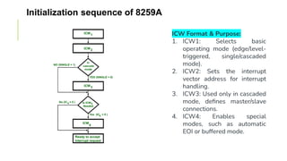
  • 47. Initialization sequence of 8259A ICW Format & Purpose: 1. ICW1: Selects basic operating mode (edge/level- triggered, single/cascaded mode). 2. ICW2: Sets the interrupt vector address for interrupt handling. 3. ICW3: Used only in cascaded mode, defines master/slave connections. 4. ICW4: Enables special modes, such as automatic EOI or buffered mode.
  • 48. ICW (Initialization Command Words) in 8259A
  • 49. ICW (Initialization Command Words) in 8259A
  • 50. ICW (Initialization Command Words) in 8259A
  • 51. OCW (Operation Command Words) in 8259A Purpose of ICW: • Used for controlling interrupt operations after initialization. • Total: 3 OCWs (OCW1–OCW3). OCW Format & Purpose: 1. OCW1: Enables or masks specific interrupts (IR0–IR7). 2. OCW2: Used for End of Interrupt (EOI), rotating priority, and specific interrupt handling. 3. OCW3: Controls polling mode and checks the status of interrupts. When is OCW Used? • When dynamically enabling/disabling interrupts. • When sending EOI (End of Interrupt) commands. • When switching to polling mode for software-based interrupt handling.
  • 52. OCW (Operation Command Words) in 8259A
  • 53. OCW (Operation Command Words) in 8259A
  • 54. OCW (Operation Command Words) in 8259A
  • 55. Polling in 8259A (Polled Mode) 8259A can operate in polling mode where the CPU checks its status instead of relying on INT & INTA̅ signals. In this mode, the CPU sends a poll command and reads the Interrupt Request Register (IRR) to determine pending interrupts. No need for EOI (End of Interrupt) commands since the CPU manually clears interrupts.
  • 56. Topics Covered • Interrupts in 8086, and their types, • 8086 Interrupt Structure, • Interrupt Instructions, • Hardware software and program generated interrupts in 8086, • Response to interrupt, • Interrupt Vector Table, • Interrupt acknowledge machine cycle, • 8259A: Programmable Interrupt Controller, • Operating Modes, EOI, and interfacing with 8086, • ICWs and OCWs.
  • 57. THANK YOU! Dr. RAJ GAURAV MISHRA Associate Professor – STME rajgaurav.mishra@nmims.edu