SlideShare a Scribd company logo
Manufacturing processes-I
Unit-1
Casting Processes
Unit I: CASTING PROCESSES
Syllabus
• SAND CASTING – Pattern- types, material and allowances,
• Molding sand- types, properties and testing,
• Molding – types, equipment’s, tools and machines,
• Core – types and manufacturing,
• Gating system and Riser – types and design (Numerical),
• Heating and pouring, cooling and solidification process and time
estimation (Numerical),
• Cleaning and Finishing, Defects and remedies, Inspection techniques.
• Die casting, Investment casting, Centrifugal Casting, Continuous Casting-
Types, equipment, process parameters, material to cast.
Types of manufacturing processes
Extrusion
Forging
Rolling
Bar drawing
Wiredrawing
Deformation
Centrifugal
Die casting
Investment
Permanent mold
Sand casting
Casting
Bending
Blanking
Drawing
Punching
Shearing
Spinning
Sheet
Metal
Blow molding
Casting
Compression molding
Extrusion
Injection Molding
Thermoforming
Transfer molding
Polymer
Processes
Boring
Drilling
Facing
Grinding
Milling
Planing
Turning
Sawing
ECM, EDM
Machining
Anodizing
Honing
Painting
Plating
Polishing
Finishing
Automated
Bonding
Brazing
Manual
Riveting
Soldering
Welding
Assembly
Manufacturing
Processes
Casting since about 4000 BC…
4
Ancient Greece; bronze
statue casting circa 450BC
Iron works in early Europe,
e.g. cast iron cannons from
England circa 1543
Casting
• Foundry is a process of producing metal castings.
• Casting is an operation of shaping metal by pouring it in the liquid state
into a mold followed by solidification.
• Casting is a process in which molten metal flows into a mold where it
solidifies in the shape of the mold cavity. The part produced is also called
casting.
• In some cases casting is the only method of shaping a metal or alloy: when
the alloy is not malleable and therefore it’s plastic deformation is not
possible or when a large detail of complex shape is to be produced.
Advantages
• Complex shapes
• Net-shape ability
• Very large parts
• Variety of metals
• Mass production
Disadvantages
• Poor accuracy
• Poor surface
• Internal defects
• Mechanical properties
• Environmental impact
Applications
 Big parts:
engine blocks and heads for
automotive vehicles,
wood burning stoves,
machine frames,
railway wheels, pipes, church
bells,
big statues, and pump housings
 Small parts:
dental crowns,
jewelry,
small statues, and
frying pans
Cameras
Casting Processes
• 1. Expendable mold processes
Uses an expendable mold which must be
destroyed to remove casting
Mold materials: sand, plaster & ceramic
• 2. Permanent mold processes
Uses a permanent mold which can be used
many times to produce many castings
Mold materials :Made of metal
Casting Processes
Expendable mould Permanent mould
Sand mould
Gravity die
casting
Pressure
die casting
Centrifugal
casting
Continuous
casting
Investment mould
Sand Casting
• Sand casting, the most widely used casting process, utilizes expendable
sand molds to form complex metal parts that can be made of nearly any
alloy.
• - has a low production rate.
• The sand casting process involves the use of a furnace, metal, pattern, and
sand mold.
CASTING TERMINOLOGY
• Pattern:
It is the replica of the final object to be made.
CASTING TERMINOLOGY
•Core:
A separate part of the mould, made of sand which
is placed in mould to create openings and various
shaped cavities in the castings.
CASTING TERMINOLOGY
• Flask(Mould box):
A metal or wood frame/container, without fixed top or
bottom which is used to create the mould.
CASTING TERMINOLOGY
• Mould: In sand casting, the primary piece of equipment is the mould,
which contains several components.
The mould is divided into two halves - the cope (upper half) and the
drag (bottom half), which meet along a parting line.
• Mould cavity:
The mould cavity is formed by packing sand around
the pattern in each half of the flask.
The mould cavity is made with the help of pattern.
CASTING TERMINOLOGY
• Gating system: It consist of pouring basin,sprue,runner,
gates, riser. It is used to feed the molten metal.
• (1)Pouring basin(feeder:) A small funnel shaped cavity at
the top of the mould into which the molten metal is
poured.
• (2)Sprue: The passage through which the molten metal,
from the pouring basin, reaches the mold cavity. In many
cases it controls the flow of metal into the mold.
• (3)Runner: The channel through which the molten
metal is carried from the sprue to the gate.
• (4)Gate: A channel through which the molten metal
enters the mold cavity.
• (5)Riser: A column of molten metal placed in the
mold to feed the castings as it shrinks and solidifies.
Also known as feed head.
CASTING TERMINOLOGY
CASTING TERMINOLOGY
CASTING TERMINOLOGY
Steps in Sand Casting
1
2
3
4 5
6 7 8 9
10
Fettling
What is basic requirement for sand casting
process…?
• 1. Pattern.
• 2. Core
• 3. Gating system
• 4. Sand casting
• 5. Mold
I. PATTERN
•It is the replica of the final object to be made.
•Pattern is the solid form that is used to make mold cavity.
•The quality of the castings produced depends on the design of the pattern,
its material and construction.
• One major requirement is that patterns (and therefore the mold cavity)
must be oversized
• (i) to account for shrinkage in cooling and solidification, and
• (ii) to provide enough metal for the subsequence machining operation(s).
I. PATTERN
Solidification and cooling
Shrinkage
FACTORS EFFECTING SELECTION OF PATTERN MATERIAL
1. Number of castings to be produced.
Metal pattern----- large in number.
2. Type of mold material used.
3. Kind of molding process.
4. Method of molding (hand or machine).
5. Degree of dimensional accuracy and surface finish required.
6. Minimum thickness required.
7. Shape, complexity and size of casting.
8. Cost of pattern and chances of repeat orders of the pattern
COMMON PATTERN MATERIALS
• The common materials used for making patterns are wood, metal, plastic,
plaster, wax or mercury.
Pattern properties are
• Easily worked, shaped and joined
• Light in weight
• Strong, hard, durable etc
• Resistance to wear and abrasion, chemical reaction
• Dimensionally stable
• Available at low cast
Pattern Materials
• Wood-pine (softwood),
or mahogany (hardwood),
• Metals and alloys
• Plaster of Paris
• Plastic and rubber
• Wax and resins
1. Wood- shisham, kail, deodar, teak and mahogany.
Advantages of wooden patterns
1 Wood can be easily worked.
2 It is light in weight.
3 It is easily available.
4 It is very cheap.
5 It is easy to join.
6 It is easy to obtain good surface finish.
7 Wooden laminated patterns are strong.
8 It can be easily repaired.
Disadvantages
1 It is susceptible to moisture.
2 It tends to warp.
3 It wears out quickly due to sand abrasion.
4 It is weaker than metallic patterns.
2. Metal- cast iron, brass and bronzes and aluminum alloys.
• i). Cast Iron
Advantages
• 1. It is cheap
• 2. It is easy to file and fit
• 3. It is strong
• 4. It has good resistance against sand abrasion
• 5. Good surface finish
Disadvantages
• 1 It is heavy
• 2 It is brittle and hence it can be easily broken
• 3 It may rust
ii). Brasses and Bronzes
Advantages
• 1. Better surface finish than cast iron.
• 2. Very thin sections can be easily casted.
Disadvantages
• 1. It is costly
• 2. It is heavier than cast iron.
iii). Aluminum Alloys
Advantages
• 1. Aluminum alloys pattern does not rust.
• 2. They are easy to cast.
• 3. They are light in weight.
• 4. They can be easily machined.
Disadvantages
• 1. They can be damaged by sharp edges.
• 2. They are softer than brass and cast iron.
• 3. Their storing and transportation needs proper care.
• Iv). White Metal (Alloy of Antimony, Copper and Lead)
• Advantages
• 1. It is best material for lining and stripping plates.
• 2. It has low melting point around 260°C
• 3. It can be cast into narrow cavities.
• Disadvantages
• 1. It is too soft.
• 2. Its storing and transportation needs proper care
• 3. It wears away by sand or sharp edges.
3. Plastic
• Advantages
• lighter, stronger, moisture and wear resistant, non sticky to molding sand,
durable and they are not affected by the moisture of the molding sand.
• Moreover they impart very smooth surface finish on the pattern surface.
Disadvantages
• These materials are somewhat fragile, less resistant to sudden loading and their
section may need metal reinforcement.
• The plastics used for this purpose are thermosetting resins.
• Phenolic resin plastics are commonly used.
4. Plaster
• The main advantages of plaster are that it has high compressive
strength and is of high expansion setting type which compensate for
the shrinkage allowance of the casting metal.
• It is also preferred for production of small size intricate castings and
making core boxes.
• preferable for producing highly intricate casting.
5. Wax
• The commonly used waxes are paraffin wax, shellac wax, bees-
wax, cerasin wax, and micro-crystalline wax.
• used in the process of investment casting where accuracy is
linked with intricacy of the cast object.
TYPES OF PATTERN
1. One piece or solid pattern
2. Two piece or split pattern
3. Cope and drag pattern
4. Three-piece or multi- piece pattern
5. Loose piece pattern
6. Match plate pattern
7. Follow board pattern
8. Gated pattern
9. Sweep pattern
10. Skeleton pattern
11. Segmental or part pattern
1. Loose pattern:
• Loose pattern are patterns which are not connected to other patterns or
mounted on a plate. Loose patterns may be further classified into:
• 1. Solid or Single piece pattern
• 2. Self core pattern
• 3. Split patterns
• 4. Loose piece pattern
1.Solid Pattern/single piece pattern
• Solid pattern is made of single piece without joints, partings lines or
loose pieces. It is the simplest form of the pattern.
• It is an easy pattern to manufacture, but determining the parting line
between cope and drag is more difficult for the foundry worker.
2. Self core patterns:
• Self core type solid patterns are patterns having a hollow portion
with straight draft which is used for producing its own core during
moulding process itself.
• This type of pattern eliminates the need for core box.
3. Split Pattern:
• The split pattern is comprised of two separate parts that when put
together will represent the geometry of the casting.
• Split pattern is made in two pieces which are joined at the parting line
by means of dowel pins.
• The splitting at the parting line is done to facilitate the withdrawal of
the pattern.
4. Match Plate Pattern:
• -- high production.
• In the match plate pattern, however, each of the parts are mounted on a
plate.
• The plates come together to assemble the pattern for the casting
process.
• - more proficient and makes alignment of the pattern in the mold quick
and accurate.
5. Cope and Drag Pattern:
• Each of the two halves are mounted on a separate plate for easy
alignment of the pattern and mold.
• The cope and drag pattern enables the cope section of the mold, and
the drag section of the mold to be created separately and latter
assembled before the pouring of the casting.
6. Shell patterns:
• --used for piping work or for producing drainage fittings.
• This pattern consists of a thin cylindrical or curved metal piece parted
along the center line.
• The two halves of the pattern are held in alignment by dowels.
6. Gated patterns:
• Gated patterns are number of loose patterns connected with a gating
system.
• They are molded like a single pattern and withdrawn from the mould in
one piece thus reducing moulding time.
• Gated patterns are useful when a number of small castings are to be
produced
Eg. Investment casting
7. Sweep pattern
• Sweep patterns are used for forming large circular moulds of
symmetric kind by revolving a sweep attached to a spindle.
• Actually a sweep is a template of wood or metal and is attached to
the spindle at one edge and the other edge has a contour depending
upon the desired shape of the mould.
• The pivot end is attached to a stake of metal in the center of the
mould.
8. Skeleton pattern
• When only a small number of large and heavy castings are to be made,
it is not economical to make a solid pattern.
• In such cases, however, a skeleton pattern may be used.
• This is a ribbed construction of wood which forms an outline of the
pattern to be made.
• This frame work is filled with loam sand and rammed.
• The surplus sand is removed by stickle board.
• For round shapes, the pattern is made in two halves which are joined
with glue or by means of screws etc.
9. Three-piece or multi-piece pattern
• Some patterns are of complicated kind in shape and hence can
not be made in one or two pieces because of difficulty in
withdrawing the pattern.
• Therefore these patterns are made in either three pieces or in
multi-pieces.
• Multi molding flasks are needed to make mold from these
patterns.
10. Segmental pattern
• Patterns of this type are generally used for circular castings, for example
wheel rim, gear blank etc.
• Such patterns are sections of a pattern so arranged as to form a complete
mould by being moved to form each section of the mould.
• The movement of segmental pattern is guided by the use of a central
pivot.
11. Follow board pattern
• When the use of solid or split patterns becomes difficult, a
contour corresponding to the exact shape of one half of the
pattern is made in a wooden board, which is called a follow board
and it acts as a molding board for the first molding operation
PATTERN ALLOWANCES
• The size of a pattern is never kept the same as that of the desired
casting because of the fact that during cooling the casting is subjected
to various effects and hence to compensate for these effects,
corresponding allowances are given in the pattern.
• These various allowances given to pattern can be enumerated as,
• allowance for shrinkage,
• allowance for machining,
• allowance for draft,
• allowance for rapping or shake,
• allowance for distortion and
• allowance for mould wall movement.
1. Shrinkage Allowance
• In practice it is found that all common cast metals shrink a significant
amount when they are cooled from the molten state.
The total contraction in volume
• 1. Liquid contraction, i.e. the contraction during the period in which the
temperature of the liquid metal or alloy falls from the pouring temperature to
the liquidus temperature.
• 2. Contraction on cooling from the liquidus to the solidus temperature, i.e.
solidifying contraction.
• 3. Contraction that results there after until the temperature reaches the room
temperature. This is known as solid contraction.
• The first two of the above are taken care of by proper gating and
risering.
• Only the last one, i.e. the solid contraction is taken care by the pattern
makers by giving a positive shrinkage allowance.
• The contraction allowances for different metals and alloys such as
• Cast Iron 10 mm/m.
• Brass 16 mm/m,
• Aluminium Alloys. 15 mm/m.,
• Steel 21 mm/m,
• Lead 24 mm/m.
• Copper 16mm/m.
In fact, there is a special rule known as the pattern marks contraction
rule / shrinkage rule in which the shrinkage of the casting metals is
added.
2. Machining Allowance
• It is a positive allowance given to compensate for the amount of
material that is lost in machining or finishing the casting.
• If this allowance is not given, the casting will become undersize after
machining.
• The amount of this allowance depends on the size of casting, methods
of machining and the degree of finish.
• the value varies from 3 mm. to 18 mm.
3. Draft or Taper Allowance
• Taper allowance is also a positive allowance and is given on all the
vertical surfaces of pattern so that its withdrawal becomes easier.
• The normal amount of taper on the external surfaces varies from 10 mm
to 20 mm/mt. On interior holes and recesses which are smaller in size,
the taper should be around 60 mm/mt. These values are greatly affected
by
• the size of the pattern and the molding method. In machine molding its,
value varies from 10 mm to 50 mm/mt.
4. Rapping or Shake Allowance
• Actually by rapping, the external sections move outwards increasing the
size and internal
• sections move inwards decreasing the size.
• This movement may be insignificant in the case of
• small and medium size castings, but it is significant in the case of large
castings.
• This allowance is kept negative and hence the pattern is made
slightly smaller in dimensions 0.5-1.0 mm.
5. Distortion Allowance
• This allowance is applied to the castings which have the tendency to
distort during cooling due to thermal stresses developed.
• For example a casting in the form of U shape will contract at the closed
end on cooling, while the open end will remain fixed in position.
• Therefore, to avoid the distortion, the legs of U pattern must converge
slightly so that the sides will remain parallel after cooling.
II. CORE
II. Core
• Cores serve to produce internal surfaces in castings, in some cases, they
have to be supported by chaplets for more stable positioning.
• For producing hallow casting.
• The core is normally a disposable item that is destroyed to get it out of
the piece.
Eg. the use of cores is in the
casting of engine blocks
Definition of core:-
Cores are compact mass of core sand that when placed in mould cavity
at required location with proper alignment does not allow the molten
metal to occupy space for solidification in that portion and hence help to
produce hollowness in the casting.
Types of core
Cores are classified according to shape and position in the mold.
1. Horizontal core
2. Vertical core
3. Balanced core
4. Hanging and cover core –wire support
5. Wind up core- below or above parting line
6. Ram up core- before ramming
7. Kiss core - no core prints (seat)
•Horizontal
•Usually cylindrical, laid
horizontally at parting
plane
•Core rest in seats
provided by core print on
pattern
•Vertical
•Both in cope and drag
•Top and bottom provided
with taper - alignment
•Balanced
•Opening on one side of
casting
•Only one core print
•Core print is made large
to balance the weight
and sufficient support
•Long core supported by
chaplets
•Cover Cover hanging
from cope plus support
at bottom in drag
•Hanging
•Core hangs from cope
and no support at
bottom of drag
• Wing
• When hole is required in casting
above or below the parting line
• Side of core is given sufficient
amount of taper so core can be
placed easily
• Also called as drop core, tail core,
chair or saddle core
•Ram – up
•Setting the core brfore
mould is rammed
• core details located in
in-acessible position
•Kiss Core
•No core prints and no
seta is available
•Core is held between
cope and drag simply by
pressure of cope
Horizontal Vertical
Balanced
Cover
Hanging Wing
Ram-up Kiss core
Fig. Vertical core
Fig. Balancing core
CORE MAKING
• Core making basically is carried out in four stages namely
• 1. core sand preparation,
• 2. core making,
• 3. core baking and
• 4. core finishing.
i. CORE sand characteristics / properties
• It is special kind of molding sand.
• Those considerations involves
• (i) The cores are subjected to a very high temperature and hence the core
sand should be highly refractory in nature
• (ii) The permeability of the core sand must be sufficiently high as compared
to that of the molding sands so as to allow the core gases to escape through
the limited area of the core recesses generated by core prints
• (iii) The core sand should not possess such materials which may produce
gases while they come in contact with molten metal and
• (iv) The core sand should be collapsible in nature, i.e. it should disintegrate
after the metal solidifies, because this property will ease the cleaning of the
casting.
• The main constituents of the core sand are pure silica sand and a binder.
• Silica sand is preferred because of its high refractoriness.
• For higher values of permeability sands with coarse grain size
distribution are used.
• The main purpose of the core binder is to hold the grains together,
impart strength and sufficient degree collapsibility.
Core Material
Commonly used binders in core making..
1. Cereal binder
It develops green strength, baked strength and collapsibility in core. The
amount of these binders used varies from 0.2 to 2.2% by weight in the core
sand.
2. Protein binder
It is generally used to increase collapsibility property of core.
3. Thermo setting resin
It is gaining popularity nowadays because it imparts high strength,
collapsibility to core sand and it also evolve minimum amount of mold and core
gases which may produce defects in the casting. The most common binders
under this group are phenol formaldehyde and urea formaldehyde.
4. Sulphite binder
Sulphite binder is also sometimes used in core but along with certain
amount of clay.
5. Dextrin
It is commonly added in core sand for increasing collapsibility and baked
strength of core
1.Core blowing machines
• The basic principle of core blowing machine comprises of filling the core
sand into the core box by using compressed air.
• The velocity of the compressed air is kept high to obtain a high velocity of
core sand particles, thus ensuring their deposit in the remote corners the
core box.
• On entering the core sand with high kinetic energy, the shaping and
ramming of core is carried out simultaneously in the core box.
ii. The process of core making is basically mechanized using core
blowing, core ramming and core drawing machines
2. Core ramming machines
• Cores can also be prepared by ramming core sands in the core boxes by
machines based on the principles of squeezing, jolting and slinging.
• Out of these three machines, jolting and slinging are more common for
core making.
3. Core drawing machines
• The core drawing is preferred when the core boxes have deep draws.
After ramming sand in it, the core box is placed on a core plate supported
on the machine bed.
• A rapping action on the core box is produced by a vibrating vertical plate.
• This rapping action helps in drawing off the core from the core box.
• After rapping, the core box, the core is pulled up thus leaving the core on
the core plate.
• The drawn core is then baked further before its use in mold cavity to
produce hollowness in the casting.
iii. Core baking
• Once the cores are prepared, they will be baked in a baking ovens or
furnaces.
• The main purpose of baking is to drive away the moisture and hard en the
binder, thereby giving strength to the core.
Dielectric bakers
• After baking of cores, they are smoothened using dextrin and water
soluble binders.
Type of cores
1. GREEN SAND CORES
• Green sand cores are made by green sand containing moist condition about
5% water and 15- 30 % clay.
• It imparts very good permeability to core and thus avoids defects like
shrinkage or voids in the casting. Green sand cores are not dried.
• They are poured in green condition and are generally preferred for simple,
small and medium castings.
• Such cores possess less strength in comparison to dry sand cores and hence
cannot be stored for longer period.
2. DRY SAND CORES
• Dry sand cores are produced by drying the green sand cores to about 110°C.
• These cores possess high strength rigidity and also good thermal stability.
• These cores can be stored for long period and are more stable than green
sand core. They are used for large castings.
• They also produce good surface finish in comparison to green sand cores.
Core Box
• Any kind of hollowness in form of holes and recesses in castings is
obtained by the use of cores.
• Cores are made by means of core boxes comprising of either single or in
two parts.
• Core boxes are generally made of wood or metal and are of several
types.
• The main types of core box are
• half core box,
• dump core box,
• split core box,
• strickle core box,
• right and left hand core box and
• loose piece core box.
1. Half core box
• This is the most common type of core box. The two identical
halves of a symmetrical core prepared in the half core box.
• Two halves of cores are pasted or cemented together after
baking to form a complete core.
2. Dump core box
• Dump core box is similar in construction to half core box.
• The cores produced do not require pasting, rather they are complete by
themselves.
• If the core produced is in the shape of a slab, then it is called as a slab
box or a rectangular box.
• A dump core-box is used to prepare complete core in it. Generally
cylindrical and rectangular cores are prepared in these boxes.
3. Split core box
• Split core boxes are made in two parts.
• They form the complete core by only one ramming.
• The two parts of core boxes are held in position by means of clamps and
their alignment is maintained by means of dowel pins and thus core is
produced.
4. Right and left hand core box
• Some times the cores are not symmetrical about the center line. In such
cases, right and left hand core boxes are used. The two halves of a core
made in the same core box are not identical and they cannot be pasted
together.
5. Strickle core box
• This type of core box is used when a core with an irregular shape is
desired. The required shape is achieved by striking oft the core sand
from the top of the core box with a wooden piece, called as strickle
board. The strickle board has the same contour as that of the required
core.
6. Loose piece core box
• Loose piece core boxes are highly suitable for making cores where
provision for bosses, hubs etc. is required. In such cases, the loose
pieces may be located by dowels, nails and dovetails etc. In certain
cases, with the help of loose pieces, a single core box can be made to
generate both halves of the right-left core.
Color codification for patterns and core boxes
• There is no set or accepted standard for representing of various surfaces of
pattern and core boxes by different colors.
• The American practice is the most popular.
• In this practice, the color identification is as follows.
surfaces color
Unfinished Surfaces black
Machined surfaces red
Core prints yellow
Seats for loose pieces red stripes on yellow background
Stop-offs black stripes on yellow base
CORE PRINTS
• When a hole blind or through is needed in the casting, a core is placed in
the mould cavity to produce the same.
• The core has to be properly located or positioned in the mould cavity on
pre-formed recesses or impressions in the sand.
• To form these recesses or impressions for generating seat for placement
of core, extra projections are added on the pattern surface at proper
places.
• These extra projections on the pattern (used for producing recesses in the
mould for placement of cores at that location) are known as core prints.
• The core is placed in the metal casting after the removal of the
pattern.
III. Gating System
• In order for this mold to be functional to manufacture a casting, in
addition to the impression of the part, the mold cavity will also need to
include a gating system.
• Sometimes the gating system will be cut by hand or in more adept
manufacturing procedures the gating system will be incorporated into
the pattern along with the part.
• Basically a gating system functions during the metal casting operation to
facilitate the flow of the molten material into the mold cavity.
Unit_1_Casting Processes.pdf
Pouring Basin:
• This is where the molten metal employed to manufacture the part
enters the mold. The pouring basin should have a projection with a
radius around it to reduce turbulence.
Down Sprue:
• From the pouring basin the molten metal for the casting travels through
the down sprue. This should be tapered so its cross-section is reduced
as it goes downward.
Sprue Base:
• The down sprue ends at the sprue base. It is here that the casting's
inner cavity begins.
Gate
• It is a small passage or channel being cut by gate cutter which connect
runner with the mould cavity and through which molten metal flows to
fill the mould cavity.
• It feeds the liquid metal to the casting at the rate consistent with the
rate of solidification.
Choke
• It is that part of the gating system which possesses smallest cross-
section area.
• In choked system, gate serves as a choke, but in free gating system sprue
serves as a choke.
Chaplets
• Chaplets are metal distance pieces inserted in a mould either to prevent
shifting of mould or locate core surfaces.
• The distances pieces in form of chaplets are made of parent metal of
which the casting is. These are placed in mould cavity suitably which
positions core and to give extra support to core and mould surfaces.
• Its main objective is to impart good alignment of mould and core surfaces
and to achieve directional solidification.
• When the molten metal is poured in the mould cavity, the chaplet melts
and fuses itself along with molten metal during solidification and thus
forms a part of the cast material.
Chills
• At that particular position, the special mould surface for fast extraction of
heat is to be made.
• The fast heat extracting metallic materials known as chills will be
incorporated separately along with sand mould surface during molding.
• Thus, the main function of chill is to provide a hard surface at a localized
place in
• the casting by way of special and fast solidification.
Runners:
• Runners are passages that distribute the liquid metal to the different
areas inside the mold.
Main Cavity:
• The impression of the actual part to be cast is often referred to as the
main cavity.
Vents:
• Vents help to assist in the escape of gases that are expelled from the
molten metal during the solidification phase of the metal casting process.
Risers:
• Risers are reservoirs of molten material. They feed this material to
sections of the mold to compensate for shrinkage as the casting solidifies.
There are different classifications for risers.
Top Risers: Risers that feed the metal casting from the top.
Side Risers: Risers that feed the metal casting from the side.
Blind Risers: Risers that are completely contained within the mold.
Open Risers: Risers that are open at the top to the outside environment.
Figure . Illustrates the difference
between top risers and side
risers.
Why Riser?
• The shrinkage occurs in three stages,
1. When temperature of liquid metal drops from pouring to zero
temperature
2. When the metal changes from liquid to solid state, and
3. When the temperature of solid phase drops from freezing to
room temperature
• The shrinkage for stage 3 is compensated by providing shrinkage allowance on
pattern, while the shrinkage during stages 1 and 2 are compensated by
providing risers.
• The riser should solidify in the last otherwise liquid metal will start flowing
from casting to riser. It should promote directional solidification. The shape,
size and location of the risers are important considerations in casting design
IV. MOLDING SAND
• The general sources of receiving molding sands are the beds of sea,
rivers, lakes, granular elements of rocks, and deserts.
• The common sources of molding sands available in India are as follows:
• 1 Batala sand ( Punjab)
• 2 Ganges sand (Uttar Pradesh)
• 3 Oyaria sand (Bihar)
• 4 Damodar and Barakar sands (Bengal- Bihar Border)
• 5 Londha sand (Bombay)
• 6 Gigatamannu sand (Andhra Pradesh) and
• 7 Avadi and Veeriyambakam sand (Madras)
• Molding sands may be of two types namely natural or synthetic.
• Natural molding sands contain sufficient binder.
• Whereas synthetic molding sands are prepared artificially using basic
sand molding constituents (silica sand in 88-92%, binder 6-12%, water or
moisture content 3-6%) and other additives in proper proportion by
weight with perfect mixing and mulling in suitable equipments.
CONSTITUENTS OF MOLDING SAND
• The main constituents of molding sand involve silica sand, binder,
moisture content and additives.
1. Silica sand
• Silica sand in form of granular quarts is the main constituent of molding
sand having enough refractoriness which can impart strength, stability
and permeability to molding and core sand.
• But along with silica small amounts of iron oxide, alumina, lime stone,
magnesia, soda and potash are present as impurities.
• The chemical composition of silica sand gives an idea of the impurities
like lime, magnesia, alkalis etc. present.
• The presence of excessive amounts of iron oxide, alkali oxides and lime
can lower the fusion point to a considerable extent which is undesirable.
• The silica sand can be specified according to the size (small, medium and
large silica sand grain) and the shape (angular, sub-angular and
rounded).
2. Binder
• In general, the binders can be either inorganic or organic substance.
• The inorganic group includes clay sodium silicate and port land cement
etc. In foundry shop, the clay acts as binder which may be Kaolonite, Ball
Clay, Fire Clay, Limonite, Fuller’s earth and Bentonite.
• Binders included in the organic group are dextrin, molasses, cereal
binders, linseed oil and resins like phenol formaldehyde, urea
formaldehyde etc.
• Organic binders are mostly used for core making.
• Among all the above binders, the bentonite variety of clay is the most
common.
• However, this clay alone can not develop bonds among sand grins
without the presence of moisture in molding sand and core sand.
3. Moisture
• The amount of moisture content in the molding sand varies generally
between 2 to 8 percent.
• This amount is added to the mixture of clay and silica sand for
developing bonds.
• This is the amount of water required to fill the pores between the
particles of clay without separating them.
• This amount of water is held rigidly by the clay and is mainly responsible
for developing the strength in the sand.
• The effect of clay and water decreases permeability with increasing clay
and moisture content.
• The green compressive strength first increases with the increase in clay
content, but after a certain value, it starts decreasing.
4 Additives
• Additives are the materials generally added to the molding and core sand
mixture to develop some special property in the sand.
4.1 Coal dust
• Coal dust is added mainly for producing a reducing atmosphere during
casting.
• This reducing atmosphere results in any oxygen in the poles becoming
chemically bound so that it cannot oxidize the metal.
• It is usually added in the molding sands for making molds for production
of grey iron and malleable cast iron castings.
4.2 Corn flour
• It belongs to the starch family of carbohydrates and is used to increase
the collapsibility of the molding and core sand.
• It is completely volatilized by heat in the mould, thereby leaving space
between the sand grains.
• This allows free movement of sand grains, which finally gives rise to
mould wall movement and decreases the mold expansion and hence
defects in castings.
• Corn sand if added to molding sand and core sand improves significantly
strength of the mold and core.
4.3 Dextrin
• Dextrin belongs to starch family of carbohydrates that behaves also in a
manner similar to that of the corn flour. It increases dry strength of the
molds.
4.4 Sea coal
• Sea coal is the fine powdered bituminous coal which positions its place
among the pores of the silica sand grains in molding sand and core sand.
• When heated, it changes to coke which fills the pores and is unaffected
by water: Because to this, the sand grains become restricted and cannot
move into a dense packing pattern.
• Thus, sea coal reduces the mould wall movement and the permeability
in mold and core sand and hence makes the mold and core surface clean
and smooth.
4.5 Pitch
• It is distilled form of soft coal. It can be added from 0.02 % to 2% in mold
and core sand.
• It enhances hot strengths, surface finish on mold surfaces and behaves
exactly in a manner similar to that of sea coal.
4.6 Wood flour
• This is a fibrous material mixed with a granular material like sand; its
relatively long thin fibers prevent the sand grains from making contact
with one another.
• It can be added from 0.05 % to 2% in mold and core sand.
• It also increases collapsibility of both of mold and core.
4.7 Silica flour
• It is called as pulverized silica and it can be easily added up to 3% which
increases the hot strength and finish on the surfaces of the molds and
cores. It also reduces metal penetration in the walls of the molds and
cores.
Moulding Sand/ Foundry Sand
• Moulding Sands:
• Most sand casting operations use Silica sand (SiO2). Usually sand used
to manufacture a mould for the casting process is held together by a
mixture of water and clay. A typical mixture by volume could be 89%
sand, 4% water, 7% clay.
Types Of Moulding Sands
• Classification of moulding sands:
1. Green sand:
• It is sand used in the wet condition for making the mould. It is mixture of
silica sand with 15-25 per cent clay and 6-8 per cent water
• As explained earlier green sand moulds are not dried and metal is
poured in them in the wet condition
• Being damp the sand can be easily worked with hand to give it any
desired shape
This sand is used for producing
small to medium sized moulds
which are not very complex
2. Dry sand:
• Dry sand is the green sand that has been dried or baked after preparing
the mould.
• Drying sand gives strength to the mould so that it can be used for larger
castings
• 3. Loam sand:
• Loam sand is sand containing up to 50 % clay which has been worked to
the consistency of builder mortar.
• This sand is used for loam sand moulds for making very heavy castings
usually with the help of sweeps and skeleton patterns.
4. Parting sand:
• This sand is used during making of the mould to ensure that green sand
does not stick to the pattern and the cope and drug parts can be easily
separated for removing the pattern without causing any damage to the
mould.
• Parting sand consists of fine grained clay free dried silica sand, sea sand or
burnt sand with some parting compounds.
• The parting compounds used include charcoal, ground bone and
limestone, groundnut shells, talc and calcium phosphate.
5. Facing sand:
• Facing sand is the sand which covers the pattern all around it. The
remaining box is filled with ordinary floor sand.
• Facing sand forms the face of the mould and comes in direct contact with
the molten metal when it is poured.
• High strength and refractoriness are required for this sand.
• It is made of silica sand and clay without the addition of any used sand.
• Graphite, mollases, plumbago etc. may be added to the facing sand.
Thickness of the sand layer varies from 20 to 30 mm.
6. Backing sand:
• Backing sand is the bulk of the sand used to back up the facing sand and to
fill up the volume of the flask.
• It consists mainly of old, repeatedly used moulding sand which is generally
black in colour due to addition of coal dust and burning on contact with hot
metal.
• Because of the colour backing sand is also sometimes called black sand.
• The main purpose for the use of backing sand is to reduce the cost of
moulding.
7. System sand:
• This is the sand used in mechanized foundries for filling the entire flask.
• No separate facing sand in used in a mechanized foundry.
• Sand, cleaned and reactivated by the addition of water and binders is used
to fill the flask. Because of the absence of any fresh sand, system sand
must have more strength, permeability and refractoriness compared to
backing sand.
8. Core sand:
• Core sand is the sand used for making cores. This is silica sand mixed with
core oil. That is why it is also called oil sand.
• The core oil consists of linseed oil, resin, light mineral oil with some
binders.
• For larger cores, sometimes pitch or flour and water may also be used to
save on cost.
Important characteristics of sand are:
• 1. These sands are refractory in nature and can withstand temperature
of the metal being poured, without fusing.
• 2. The moulding sands do not chemically react or combine with molten
metal and can therefore be used repeatedly.
• 3. The sands have a high degree of permeability and thus allow the
gases formed during pouring to escape.
• 4. The strength, permeability and hardness of the sand mix can be varied
by changing the structure or ingredients of sand.
Properties of moulding sands:
1. Strength
2. Permeability
3. Grain Size and Shape
4. Thermal stability
5. Refractoriness
6. Flow ability
7. Sand Texture
8. Collapsibility
9. Adhesiveness
10. Reusability
11. Easy of preparation and control
12. Conductivity
Strength:
• The sand should have adequate strength in its green, dry and hot states
• Green strength is the strength of sand in the wet state and is required
for making possible to prepare and handle the mould.
• If the metal is poured into a green mould the sand adjacent to the metal
dries and in the dry state it should have strength to resist erosion and
the pressure of metal.
• The strength of the sand that has been dried or basked is called dry
strength.
• At the time of pouring the molten metal the mould must be able to
withstand flow and pressure of the metal at high temperature otherwise
the mould may enlarge, crack, get washed or break
Strength of the moulding sand depends on:
• 1. Grain size and shape
• 2. Moisture content
• 3. Density of sand after ramming
• The strength of the mould increases with a decrease of grain size and
an increase of clay content and density after ramming.
• The strength also goes down if moisture content is higher than an
optimum value.
2. Permeability:
• The moulding sand must be sufficiently porous to allow the dissolved
gases, which are evolved when the metal freezes or moisture present
or generated within the moulds to be removed freely when the
moulds are poured.
• This property of sand is called porosity or permeability.
3. Grain size and shape:
• ·The size and shape of the grains in the sand determine the application
in various types of foundry. These are three different sizes of sand
grains.
• 1. Fine
• 2. Medium
• 3. Coarse
• Fine sand is used for small and intricate castings.
• Medium sand is used for benchmark and light floor works.
• If the size of casting is larger coarse sand is used
• Sand having fine, rounded grains can be closely packed and forms a
smooth surface. Although fine-grained sand enhances mould strength.
4. Thermal stability:
• The sand adjacent to the metal is suddenly heated and undergoes
expansion.
• If the mould wall is not dimensionally stable under rapid heating,
cracks, buckling and flacking off sand may occur.
5. Refractoriness:
• Refractoriness is the property of withstanding the high temperature
condition moulding sand with low refractoriness may burn on to the
casting.
• It is the ability of the moulding material to resist the temperature of
the liquid metal to be poured so that it does not get fused with the
metal.
• The refractoriness of the Silica sand is highest.
6. Flowability:
• Flowability or plasticity is the property of the sand to respond to the
moulding process so that when rammed it will flow all around the
pattern and take the desired mould shape. High flowability of sand is
desirable for the sand to get compacted to a uniform density and to get
good impression of the pattern in the mould.
Flowability is also very
important in machine
moulding
·Flowability of sand
increases as clay and
water content are
increased.
7. Sand texture:
• As mentioned earlier the texture of sand is defined by its grain size
and grain size distribution.
• The texture chosen for an application should allow the required
porosity, provide enough strength and produce the desired surface
finish on the casting.
8. Collapsibility:
• The moulding sand should collapse during the contraction of the
solidified casting it does not provide any resistance, which may result
in cracks in the castings.
• Besides these specific properties the moulding material should be
cheap, reusable and should have good thermal conductivity
9. Adhesiveness & Cohesiveness:
• The sand particles must be capable of adhering to another body, then
only the sand should be easily attach itself with the sides of the moulding
box and give easy of lifting and turning the box when filled with the
stand.
Cohesiveness
10. Reusability:
• Since large quantities of sand are used in a foundry it is very important that
the sand be reusable otherwise apart from cost it will create disposal
problems
11. Easy of preparation and control:
• Sand should lend itself to easy preparation and control by mechanical
equipment
12. Conductivity:
• Sand should have enough conductivity to permit removal of heat from the
castings.
• 1. Moisture content test
• 2. Clay content test
• 3. Grain fitness test
• 4. Permeability test
• 5. Strength test
• 6. Refractoriness test
• 7. Mould hardness test
1. Moisture content Test
2. Clay content Test
3. Chemical composition of sand
4. Grain shape and surface texture of
sand.
5. Grain size distribution of sand
6. Specific surface of sand grains
7. Water absorption capacity of sand
8. Refractoriness of sand
9. Strength Test
10. Permeability Test
11. Flowability Test
12. Shatter index Test
13. Mould hardness Test.
SAND TESTING METHODS AND SAND TESTING EQUIPMENT
1. Moisture content test:
• Moisture is the property of the moulding sand it is defined as the
amount of water present in the moulding sand. Low moisture
content in the moulding sand does not develop strength properties.
High moisture content decreases permeability.
Procedures are:
• 1. 20 to 50 gms of prepared sand is placed in the pan and is heated by an
infrared heater bulb for 2 to 3 minutes.
• 2. The moisture in the moulding sand is thus evaporated.
• 3. Moulding sand is taken out of the pan and reweighed.
• 4. The percentage of moisture can be calculated from the difference in
the weights, of the original moist and the consequently dried sand
samples.
• Percentage of moisture content = (W1-W2)/(W1) %
Where, W1-Weight of the sand before drying,
W2-Weight of the sand after drying.
2. Clay content test
• Clay influences strength, permeability and other moulding
properties. It is responsible for bonding sand particles together.
Procedures are:
• 1. Small quantity of prepared moulding sand was dried
• 2. Separate 50 gms of dry moulding sand and transfer wash bottle.
• 3. Add 475cc of distilled water + 25cc of a 3% NaOH.
• 4. Agitate this mixture about 10 minutes with the help of sand stirrer.
• 5. Fill the wash bottle with water up to the marker.
• 6. After the sand etc., has settled for about 10 minutes, Siphon out the
water from the wash bottle.
• 7. Dry the settled down sand.
• 8. The clay content can be determined from the difference in weights of
the initial and final sand samples.
Percentage of clay content = (W1-W2)/(W1) * 100
Where,
• W1-Weight of the sand before drying,
• W2-Weight of the sand after drying.
3. Grain fitness test:
• The grain size, distribution, grain fitness are determined with the help of
the fitness testing of moulding sands.
• The apparatus consists of a number of standard sieves mounted one
above the other, on a power driven shaker.
• The shaker vibrates the sieves and the sand placed on the top sieve gets
screened and collects on different sieves depending upon the various
sizes of grains present in the moulding sand.
• The top sieve is coarsest and the bottom-most sieve is the finest of all the
sieves. In between sieve are placed in order of fineness from top to
bottom.
• Procedures are:
• 1. Sample of dry sand (clay removed sand) placed in the upper sieve
• 2. Sand is vibrated for definite period
• 3. The amount of same retained on each sieve is weighted.
• 4. Percentage distribution of grain is computed.
3. Permeability test:
• The quantity of air that will pass through a standard specimen of the
sand at a particular pressure condition is called the permeability of
the sand.
• Following are the major parts of the permeability test equipment:
• 1. An inverted bell jar, which floats in a water.
• 2. Specimen tube, for the purpose of hold the equipment
• 3. A manometer (measure the air pressure)
Unit_1_Casting Processes.pdf
Steps involved are:
• 1. The air (2000cc volume) held in the bell jar is forced to pass through the
sand specimen.
• 2. At this time air entering the specimen equal to the air escaped through
the specimen
• 3. Take the pressure reading in the manometer.
• 4. Note the time required for 2000cc of air to pass the sand
• 5. Calculate the permeability number
• 6. Permeability number (N) = ((V x H) / (A x P x T))
• Where,
• V-Volume of air (cc)
• H-Height of the specimen (mm)
• A-Area of the specimen (mm2)
• P-Air pressure (gm / cm2)
• T-Time taken by the air to pass through the sand (seconds)
Strength test:
• Measurements of strength of moulding sands can be carried out on the
universal sand strength testing machine. The strength can be measured in
compression, shear and tension.
• The sands that could be tested are green sand, dry sand or core sand. The
compression and shear test involve the standard cylindrical specimen that
was used for the permeability test.
Steps involved are:
1. Specimen is held between the
grips
2. Apply the hydraulic pressure
by rotating the hand wheel
3. Taking the deformation use of
the indicators.
Refractoriness test
• The refractoriness is used to measure the ability of the sand to
withstand the higher temperature.
Steps involved are:
1. Prepare a cylindrical specimen of sand
2. Heating the specimen at 1500 C for 2
hours
3. Observe the changes in dimension and
appearance
4. If the sand is good, it retains specimen
share and shows very little expansion. If
the sand is poor, specimen will shrink and
distort.
Mould hardness test
• Hardness of the mould surface can be tested with the help of an
“indentation hardness tester”. It consists of indicator, spring loaded
spherical indenter.
The spherical indenter is penetrates into the mould
surface at the time of testing. The depth of
penetration w.r.t. the flat reference surface of the
tester.
Mould hardness number = ((P) / (D – (D2-d2))
Where,
P- Applied Force (N)
D- Diameter of the indenter (mm)
d- Diameter of the indentation (mm)
Advantages and disadvantages of sand casting
• Advantages of sand casting
• Low cost of mold materials and equipment.
• Large casting dimensions may be obtained.
• Wide variety of metals and alloys (ferrous and non-ferrous) may be cast
(including high melting point metals).
• Disadvantages of sand casting
• Rough surface.
• Poor dimensional accuracy.
• High machining tolerances.
• Coarse Grain structure.
• Limited wall thickness: not higher than 0.1”-0.2” (2.5-5 mm).
Advantages: Can produce very large parts
Can form complex shapes
Many material options
Low tooling and equipment cost
Scrap can be recycled
Short lead time possible
Disadvantages: Poor material strength
High porosity possible
Poor surface finish and tolerance
Seondary machining often required
Low production rate
High labor cost
Applications: Engine blocks and manifolds, machine bases, gears,
pulleys, crankshafts, connecting rods, and propellers,
cylinder heads, and transmission cases
V. The Mold
A typical mold is shown in figure
•The pattern is placed in the
mold and the mold material is
packed around it.
• The mold contains two parts,
the drag (bottom), and the cope
(top).
•The parting line between the
cope and drag allows for the
mold to be opened and the
pattern to be removed once the
impression has been made.
•For some moulds additional
intermediate boxes called
“Cheeks” may be required.
Mold (used in us ) / Mould ( used in Britain et al.)
• A mold is formed into the geometric shape of a desired part.
• Molten metal is then poured into the mold, the mold holds this material
in shape as it solidifies. A metal casting is created.
• Molds can be classified as either open or closed.
• A open mold is a container, like a cup, that has only the shape of the
desired part.
• The molten material is poured directly into the mold cavity which is
exposed to the open environment.
Open and Closed Mould
• Two main branches of methods can be distinguished by the basic
nature of the mold they employ.
• There is expendable mold casting and permanent mold casting.
•Expendable Mold Can
produce one metal casting only
•Made of sand, plaster, or other
similar material. Binders used
to help material hold its form.
•Mold that metal solidifies in
must be destroyed to remove
casting
•More intricate geometries are
possible for casting
•Permanent Mold Can
manufacture many metal
castings
•Usually made of metal or
sometimes a refractory ceramic
•Mold has sections that can
open or close permitting
removal of the casting
•Need to open mold limits part
shapes
Mould Making
• Making a mould properly means a casting half done.
• A sand mould is formed by packing sand into each half of the mould.
• The sand is packed around the pattern, which is a replica of the external
shape of the casting.
• When the pattern is removed, the cavity that will form the casting
remains.
• Any internal features of the casting that cannot be formed by the
pattern are formed by separate cores which are made of sand prior to
the formation of the mould.
Characteristics of Mold
• 1. The mould should be strong enough to resist erosion by the flow of the
metal and to take the weight of the metal.
• 2. The mould material should not produce too much of gases as the gases
may enter the mould cavity and get entrapped with metal or violently boil
out the metal.
• 3. The mould should be made in such a way that gases generated are
vented out of the mould.
• 4. The mould should be refractory enough to withstand the high
temperature of liquid metal.
• 5. The cores should be collapsible enough to permit contraction of the
metal after solidification.
• 6. Flow should be laminar i.e. smooth flow
• 7. There should be a proper riser system in the mould to provide
sufficient extra metal to account for the liquid and solidification
shrinkage.
• 8. The mould material and moulding process should be such that cleaning
of castings is facilitated.
Molding Tools
1.Mallet:
• It is a mallet to loosen the pattern in the mould by striking slightly, so
that it can be withdrawn without damaging the mould
• 2. Gate cutter:
• It is a metal piece to the gate the opening that connects tee sprue with
the mould cavity. (sleek)
3. Rapping plate (or) Lifting plate:
• It is used to facilitate shaking and lifting large pattern from the mold.
4. Spirit level:
• It is used to check that the sand bed, moulding box or table of moulding
machine is horizontal.
• 5. Clamps:
• Clamps are used to hold the cope and drag of the complete mould
together so that the cope may not float or rise when the molten metal is
poured into the mould.
6. Moulding box:
• Sand moulds are prepared specially constructed boxes called the
moulding boxes or flasks. The function and construction of a molding box
have already been described.
Moulding flasks
7.Shovel:
• It is just like rectangular pan fitted with a handle. It is used for
mixing the moulding sand and for moving it from one place to the
other.
8. Riddle:
• It is used for removing foreign materials like nails, shot metal
splinters of wood etc from the moulding sand.
9. Rammer:
• It is a wooden tool used for ramming or packing the sand in the
mould. Rammers are made in different shapes.
10. Strike-off bar:
• It is a cast iron or wrought iron bar with a true straight edge. It is used to
remove the surplus sand from the mould after the ramming has been
completed.
11. Vent wire:
• It is a mild steel wire used for making vents or openings in the mould.
12. Lifter:
• It is a metal piece used for patching deep section of the mould and
removing loose sand from pockets of the mould.
13. Slick:
• Different types of slicks are used for repairing and finishing moulds.
14. Trowel:
It contains of a flat and thick metal sheet
with upwards projected handle at one end. It
is used for making joints and finishing flat
surface of a mould.
15. Swab:
It is made of flax or hemp. It is used for
applying water to the mould around the
edge of the pattern.
Moulding Machines
• Moulding processes may be classified as hand moulding or machine
moulding according to whether the mould is prepared by hand tools or
with the aid of some moulding machine.
• Hand moulding is generally found to be economical when the castings
are required in a small number.
• The major functions of molding machines involves ramming of molding
sand, rolling over or inverting the mould, rapping the pattern and
withdrawing the pattern from the mould.
• Most of the molding machines perform a combination of two or more of
functions.
Types of Moulding machine:
1. Hand Operated molding machine
a. Pattern draw type
b. Pattern draw and Squeeze type
c. Pin Lift type machine
d. Roll Over type machine
2. Power operated Molding Machine
a. Squeeze machine
b. Jolt machine
c. Jolt squeeze machine
d. Jolt squeeze roll over pattern draw
machine
e. Sand Slinger
Squeezer
•1.table 2. pattern 3. flask. 4.Sand frame 5. platen
6. squeezer head. 7. frame
Squeezer
•Molding sand squeezed between machine table and
overhead squeeze board
•Pneumatic or hydraulic
•Top squeezing
•Bottom squeezing
•Limitation- sand is packed more densely on top of
mould
•Density deceases uniformly with depth
•At parting plane density is lowest
•Restricted to molds up to 150 mm depth
Jolt machine
•1.table.3.patern and
flask.8. plunger.9
hose.10. channel.
•11. opening
•12. guide cylinder
•13. springs
Unit_1_Casting Processes.pdf
•Flask is filled with moulding sand
•Table supporting flask is raised and dropped in
succession
•Due to sudden change in inertia – sand gets packed
and rammed
•Action of raising and sudden dropping – jolt
•Drawback – sand is rammed hardest at parting
plane sand remains les dense at tops
•Preferred fro horizontal surfaces
Jolt squeeze machine
• Jolting action to consolodate sand on face of pattern
• Squeezing – desired density throughout mass of sand
• Mold with maximum hardness,unform ramming
Sand slinger
•Overhead impellar
head 1. housing. 2.
blade 3. opening 4.
outlet
•Conveyor buckets
Slinging – consolidation and ramming due to impact of sand
which falls at very high velocity
Rate – 500 to 2000kg per min.
Mold of adequate strength , hardness
Sand slinger
Jolt-Squeeze machine
5. Pattern draw machines
• These machines enable easy withdrawal of patterns from the molds.
• They can be of the kind of stripping plate type and pin lift or push off
type.
• The pattern is drawn through the stripping plate either by raising the
stripping plate and the mould up and keeping the pattern stationary or
by keeping the stripping plate and mould stationary and moving the
pattern supporting ram downwards along with the pattern and pattern
plate.
• A suitable mechanism can be incorporated in the machine for these
movements.
•6. stripping pins
•1.pattern, 3. pattern plate, table 5, molding box 2
•4. stripping plate between patern plate and flask
6 Roll-over machine
• The pattern is mounted on a plate which is secured to the roll-over
frame.
• The platen of the machine can be moved up and down.
• For preparation of the mould, the roll-over frame is clamped in
position with the pattern facing upward.
• Molding box is placed over the pattern plate and clamped properly.
• Molding sand is then filled in it and rammed by hand and the extra
molding sand is struck off and molding board placed over the box and
clamped to it.
•Turn over
•Flask together with work
table rotates 1800 and
pin 6 lifts table with
pattern
•Pins 6
Foundry Safety
Hand Pouring Equipment
Ladles
• Moving molten metal from melting furnace to mold is
sometimes done using crucibles
• More often, transfer is accomplished by ladles
Figure 11.21 Two common types of ladles: (a) crane ladle, and
(b) two-man ladle.
©2007 John Wiley & Sons, Inc. M P Groover, Fundamentals of Modern Manufacturing 3/e
The casting process ( Special Casting process)
1 - Expendable mold casting
(sand, plastic, shell, and investment (lost-wax technique) mouldings.)
2 - Nonexpendable mold casting
(permanent, die, centrifugal, and continuous casting).
Classification of die casting:
(a)Gravity Die Casting (also called permanent mould process)
(b)Pressure Die Casting
Unit_1_Casting Processes.pdf
Precision or investment casting (lost wax
casting)
• Investment (lost wax) casting is a method of precision casting
complex near-net-shape details using replication of wax patterns.
• Precision or investment casting employed techniques that enable
very smooth highly accurate castings to be made from both ferrous
and non-ferrous alloys
• The process is useful in casting unmachinable alloys and radioactive
metals.
• In investment casting, the pattern is made of wax, which melts after
making the mold to produce the mold cavity.
Ceramic
particles, wet
plaster Investment,
up to 3-5 mm
Ceramic slurry materials
Mullite: Al2O3 44-48%, SiO2
47-51%, Fe2O3 max. 1%, TiO2
max. 1%.
Zircon flour.
Binders: Colloidal Silica SiO2
25-45%, Na2O max.1% in
distilled water;
sodium silicate
NaO*nSiO2*mH2O; ethyl
silicate Si(OC2H5)4.
Unit_1_Casting Processes.pdf
Investment casting process
• The investment casting process uses expendable patterns made of investment
casting wax.
• The wax patterns are commonly prepared by injection molding technology
which involves injection of wax into a prefabricated die having the same
geometry of the cavity as the desired cast part.
• The wax patterns are then attached to a gating system (a set of channels through
which a molten metal flows to the mold cavity).
• The next stage is the shell building - the wax assembly is immersed into
refractory ceramic slurry of hardening mixtures followed by drying. This
operation is repeatedly carried out resulting in formation of a solid ceramic shell
of 1/4” -3/8” (6mm – 9mm) thick.
• The next stage is dewax. At this stage the assembly is heated in an autoclave
where the most of the wax is melted out. This operation is followed by burning
out the residual wax in a furnace.
• The mold is then preheated to 1830°F (1000°C). Now the mold is ready for filling
with a molten metal.
• Casting stage is conventional operation involving pouring a molten metal into
the shell through the gating system.
• After the metal has solidified and cooled to a desired temperature, the shell is
broken and the castings are cut away from the gates and sprue.
• The last stage is finishing carried out by sandblasting or machining.
Advantages and disadvantages of investment casting
Advantages:
• Excellent surface finish.
• Tight dimensional tolerances.
• Complex and intricate shapes may be produced.
• Capability to cast thin walls.
• Wide variety of metals and alloys (ferrous and non-ferrous) may be cast.
• Draft is not required in the molds design.
• Low material waste.
Disadvantages:
• Individual pattern is required for each casting.
• Limited casting dimensions.
• Relatively high cost (tooling cost, labor cost).
Turbine blades
Applications:
Turbine blades, armament parts, pipe
fittings, lock parts, handtools,
art pieces, jewelry, dental fixtures,
automotive, aircraft, and military
industries.
Die Casting
A permanent mold casting process in which molten metal is injected
into mold cavity under high pressure up to 30,000 psi (200 MPa).
• Pressure is maintained during solidification, then mold is opened and
part is removed
• Molds in this casting operation are called dies; hence the name die
casting
• Use of high pressure to force metal into die cavity is what
distinguishes this from other permanent mold processes
Die Casting Machines
• Designed to hold and accurately close two mold halves and keep them
closed while liquid metal is forced into cavity
• Two main types:
1. Hot-chamber machine
2. Cold-chamber machine
(1) Cold-chamber Die Casting:
• Material to be cast is molten outside the machine.
• Used for materials having high melting temperature Tm> 550°C, i.e.
brass, aluminum, and magnesium.
(2) Hot-chamber Die Casting:
• Materials to be cast is molten inside the machine.
• Used for materials having low melting temperature Tm< 550°C, i.e. zinc,
tin, and lead.
Hot-Chamber Die Casting
Metal is melted in a container, and a piston injects liquid metal under high
pressure into the die
• High production rates - 500 parts per hour not uncommon
• Applications limited to low melting - point metals that do not chemically
attack plunger and other mechanical components
• Casting metals: zinc, tin, lead, and magnesium
Unit_1_Casting Processes.pdf
Hot-Chamber Die Casting
Figure. Cycle in hot-chamber casting: (1) with die closed and plunger
withdrawn, molten metal flows into the chamber (2) plunger forces metal in
chamber to flow into die, maintaining pressure during cooling and
solidification.
Cold-Chamber Die Casting Machine
• Molten metal is poured into unheated chamber from external melting
container, and a piston injects metal under high pressure into die
cavity
• High production but not usually as fast as hot-chamber machines
because of pouring step
• Casting metals: aluminum, brass, and magnesium alloys
• Advantages of cold-chamber process favor its use on low
melting - point alloys (zinc, tin, lead)
Unit_1_Casting Processes.pdf
Cold-Chamber Die Casting
Figure 11.14 Cycle in cold-chamber casting: (1) with die closed
and ram withdrawn, molten metal is poured into the chamber
Molds for Die Casting
• Usually made of tool steel, mold steel, or maraging steel
• Tungsten and molybdenum (good refractory qualities) used to die cast
steel and cast iron
• Ejector pins required to remove part from die when it opens
• Lubricants must be sprayed into cavities to prevent sticking
Common metals for die
casting.
Alloys of aluminum
Zinc
Magnesium
Lead
Copper
Tin
Die casting
Advantages:
Can produce large parts
Can form complex shapes
High strength parts
Very good surface finish and accuracy
High production rate
Low labor cost
Scrap can be recycled
Disadvantages:
Trimming is required
High tooling and equipment cost
Limited die life
Long lead time
Applications:
Engine components, pump components, automobile
components, household appliances, railway and aircraft
fittings, bath room hardware, business machines, locks,
pullers
Unit_1_Casting Processes.pdf
Centrifugal casting
• Centrifugal casting is a method of casting parts having axial
symmetry. The method involves pouring molten metal into a
cylindrical mold spinning about its axis of symmetry.
• The mold is kept rotating till the metal has solidified.
•
• As the mold material steels, Cast irons, Graphite or sand may be used.
• The rotation speed of centrifugal mold is commonly about 1000 RPM
(may vary from 250 RPM to 3600 RPM).
Centrifugal casting is carried out as follows
• The mold wall is coated by a refractory ceramic coating (applying ceramic
slurry, spinning, drying and baking).
• Starting rotation of the mold at a predetermined speed.
• Pouring a molten metal directly into the mold (no gating system is
employed).
• The mold is stopped after the casting has solidified.
• Extraction of the casting from the mold.
The centrifugal group includes:
A. True centrifugal casting
B. Semi-centrifugal casting
C. Centrifuge casting
Unit_1_Casting Processes.pdf
A. True Centrifugal Casting
Fig. Setup for true centrifugal casting.
2.03.2021 CHAPTER3 SPECIALCASTINGPROCESSES 203
 Non-metallic and slag inclusions
and gas bubbles being less dense
than the melt are forced to the
inner surface of the casting by
the centrifugal forces.
 This impure zone is then removed
by machining.
 used for manufacturing of iron
pipes, bushings, wheels, pulleys
bi-metal steel-bronze bearings
and other parts possessing axial
symmetry.
B. Semi-centrifugal Casting
Centrifugal force is used to produce solid castings rather than tubular parts
• Molds are designed with risers at center to supply feed metal
• Density of metal in final casting is greater in outer sections than at center
of rotation
• Often used on parts in which center of casting is machined away, thus
eliminating the portion where quality is lowest
• The process is suitable for large axis-symmetrical castings like gear
blanks, fly wheels and track wheels.
Semi-centrifugal casting
C. Centrifuge Casting
Mold is designed with part cavities located away from axis of rotation,
so that molten metal poured into mold is distributed to these cavities
by centrifugal force
• Used for smaller parts
• Radial symmetry of part is not required as in other centrifugal casting
methods
The process is used
on parts in which the
center of the casting
is machined away,
such as wheels and
pulleys.
Centrifuge Casting
Continuous casting
• Continuous casting is a casting method, in which the steps of pouring,
solidification and withdrawal (extraction) of the casting from an open end
mold are carried out continuously.
• Cross-sectional dimensions of a continuous casting are constant along the
casting length and they are determined only by the dimensions of the mold
cavity.
• The length of a continuous casting is limited by the life time of the mold.
• Continuous casting technology is used for both ferrous and non-ferrous
alloys.
Depending on the mold position (vertical or horizontal) continuous casting
machines may be vertical or horizontal:
• Vertical continuous casting
• Horizontal continuous casting
Vertical continuous casting
• Molten metal is continuously supplied from the ladle to the
intermediate ladle (tundish) from which it is continuously poured into
the mold at a controllable rate keeping the melt level at a constant
position.
• The water-cooled copper mold (primary cooling zone) extracts the heat
of the metal causing its solidification. The mold oscillates in order to
prevent sticking with the casting.
• When the casting goes out from the mold it is cooled in the secondary
cooling zone by water (or water with air) sprayed on the casting
surface.
• The casting is continuously extracted from the mold by the withdrawal
unit followed by a cut-off unit.
• Then a molten metal is poured into the mold where it solidifies and
grips the end of the dummy bar.
Unit_1_Casting Processes.pdf
Horizontal continuous casting
• Horizontal continuous casting machine is generally used for casting
non-ferrous alloys.
• Horizontal continuous casting in stationary mold with graphite
water-cooled molds, Twin-roll caster and Twin-belt caster are most
popular methods of this type.
• Due to the water cooling (primary and secondary) solidification rate
provided by continuous casting is higher than in other casting
methods therefore continuous castings have more uniform and finer
grain structure and enhanced mechanical properties.
Unit_1_Casting Processes.pdf
2.03.2021 CHAPTER3 SPECIALCASTINGPROCESSES 214
Comparison of Casting Processes
Unit_1_Casting Processes.pdf
Additional Steps After Solidification
• Trimming
• Removing the core
• Surface cleaning
• Inspection
• Repair, if required
• Heat treatment
Trimming
Removal of sprues, runners, risers, parting-line flash, fins, chaplets,
and any other excess metal from the cast part
• For brittle casting alloys and when cross sections are relatively small,
appendages can be broken off
• Otherwise, hammering, shearing, hack-sawing, band-sawing,
abrasive wheel cutting, or various torch cutting methods are used
Removing the Core
If cores have been used, they must be removed
• Most cores are bonded, and they often fall out of casting as the
binder deteriorates
• In some cases, they are removed by shaking casting, either manually
or mechanically
• In rare cases, cores are removed by chemically dissolving bonding
agent
• Solid cores must be hammered or pressed out
Cleaning and Finishing
1. Casting is taken out of the mould by shaking and the Moulding sand is
recycled often with suitable additions.
2. The remaining sand, some of which may be embedded in the casting, is
removed by means of Shot blasting.
3. The excess material in the form of sprue, runners, gates etc., along with
the flashes formed due to flow of molten metal into the gaps is broken
manually in case of brittle casting or removed by sawing and grinding in
case of ductile grinding.
4. The entire casting is then cleaned by either shot blasting or chemical
pickling.
5. Sometimes castings are heat treated to achieve better mechanical
properties.
Surface Cleaning
Removal of sand from casting surface and otherwise enhancing
appearance of surface
• Cleaning methods: tumbling, air-blasting with coarse sand grit or
metal shot, wire brushing, buffing, and chemical pickling
• Surface cleaning is most important for sand casting
• In many permanent mold processes, this step can be
avoided
• Defects are possible in casting, and inspection is needed to detect
their presence
Heat Treatment
• Castings are often heat treated to enhance properties
• Reasons for heat treating a casting:
• For subsequent processing operations such as machining
• To bring out the desired properties for the application of
the part in service
Casting Quality
• There are numerous opportunities for things to go wrong in a casting
operation, resulting in quality defects in the product
• The defects can be classified as follows:
• General defects common to all casting processes
• Defects related to sand casting process
Casting defects
Surface
Defect
Internal
Defect
Visible defects
Blow
Scar
Blister
Drop
Scab
Penetration
Buckle
Blow holes
Porosity
Pin holes
Inclusions
Dross
Wash
Rat tail
Swell
Misrun
Cold shut
Hot tear
Shrinkage/Shift
A casting that has solidified before completely filling mold
cavity
Casting Defects: Misrun
Two portions of metal flow together but there is a lack of fusion due to
premature freezing
Casting Defects: Cold Shut
Metal splatters during pouring and solid globules form and become entrapped in
casting
Casting Defects: Cold Shot
Depression in surface or internal void caused by solidification shrinkage
that restricts amount of molten metal available in last region to freeze
Casting Defects: Shrinkage Cavity
Balloon-shaped gas cavity caused by release of mold gases during pouring
Sand Casting Defects: Sand Blow/ blow holes
Blow holes are large spherical shaped gas bubbles, while porosity indicates a
large number of uniformly distributed tiny holes. Pin holes are tiny blow
holes appearing just below the casting surface.
Sand Casting Defects: Pin Holes and porosity
• Hot tears are ragged irregular internal or external cracks occurring
immediately after the metal have solidified.
• Hot tears occur on poorly designed castings having abrupt section changes
or having no proper fillets or corner radii. Wrongly placed chills.
Sand Casting Defects: Hot tears
When fluidity of liquid metal is high, it may penetrate into sand mold or core,
causing casting surface to consist of a mixture of sand grains and metal
Sand Casting Defects: Penetration
A step in cast product at parting line caused by sidewise relative
displacement of cope and drag
Sand Casting Defects: Mold Shift/ Mismatch
Sand Casting Defects: Sand Inclusions
Inclusions are the non-metallic particles in the metal matrix,
Lighter impurities appearing the casting surface are dross.
• Scabs are rough, irregular projections on surface of castings containing
embedded sand.
• Scabs occur when a portion on the face of mould or core lifts and metal
flows underneath in a thin layer.
Sand Casting Defects: Scabs
• Scar is shallow blow generally occurring on a flat surface. A
scar covered with a thin layer of metal is called blister.
Sand Casting Defects: Scar and Blister
Sand Casting Defects: Rat tails
Rat tail is a long, shallow, angular depression caused by
expansion of the sand
• Drop is an irregularly-shaped projection on the cope surface
caused by dropping of sand.
Sand Casting Defects: Drop
• Wash is a low projection near the gate caused by erosion of sand by the
flowing metal. Swell is the deformation of vertical mould surface due to
hydrostatic pressure caused by moisture in the sand.
Sand Casting Defects: Wash and swell
Unit_1_Casting Processes.pdf
Classification of casting defects
Casting defects
Surface
Defect
Internal Defect Visible defects
Blow
Scar
Blister
Drop
Scab
Penetration
Buckle
Blow holes
Porosity
Pin holes
Inclusions
Dross
Wash
Rat tail
Swell
Misrun
Cold shut
Hot tear
Shrinkage/Shift
Surface Defects
• These are due to poor design and quality of sand molds and general cause is
poor ramming
• Blow is relatively large cavity produced by gases which displace molten metal
from convex surface. Scar is shallow blow generally occurring on a flat surface.
A scar covered with a thin layer of metal is called blister. These are due to
improper permeability or venting. Sometimes excessive gas forming
constituents in moulding sand
• Drop is an irregularly-shaped projection on the cope surface caused by dropping
of sand.
• A scab when an up heaved sand gets separated from the mould surface and the
molten metal flows between the displaced sand and the mold.
• Penetration occurs when the molten metal flows between the sand particles in
the mould. These defects are due to inadequate strength of the mold and high
temperature of the molten metal adds on it.
• Buckle is a vee-shaped depression on the surface of a flat casting caused by
expansion of a thin layer of sand at the mould face. A proper amount of volatile
additives in moulding material could eliminate this defect by providing room for
expansion.
Internal Defects
• The internal defects found in the castings are mainly due to trapped
gases and dirty metal. Gases get trapped due to hard ramming or
improper venting. These defects also occur when excessive moisture
or excessive gas forming materials are used for mould making.
• Blow holes are large spherical shaped gas bubbles, while porosity
indicates a large number of uniformly distributed tiny holes. Pin holes
are tiny blow holes appearing just below the casting surface.
• Inclusions are the non-metallic particles in the metal matrix, Lighter
impurities appearing the casting surface are dross.
Visible Defects
• Insufficient mould strength, insufficient metal, low pouring temperature, and bad
design of casting are some of the common causes.
• Wash is a low projection near the gate caused by erosion of sand by the flowing
metal. Rat tail is a long, shallow, angular depression caused by expansion of the
sand. Swell is the deformation of vertical mould surface due to hydrostatic
pressure caused by moisture in the sand.
• Misrun and cold shut are caused by insufficient superheat provided to the liquid
metal.
• Hot tear is the crack in the casting caused by high residual stresses.
• Shrinkage is essentially solidification contraction and occurs due to improper use
of Riser.
• Shift is due to misalignment of two parts of the mould or incorrect core location.
Inspection of Castings
• Inspections may be in process inspections or finished product
inspections.
• In process inspections are carried out before a lot of castings have been
completed to detect any flaws that may have occurred in the process so
that corrective measures can be taken to remove the defect in the
remaining units.
• Finished product inspections are carried out after the castings have all
been completed to make sure that the product meets the requirements
specified by the customer.
• Two types of methods- destructive or non-destructive
• Destructive methods generally relate to sawing or breaking off of parts
of the castings at places where voids or internal defects are suspected.
Castings may also be damaged during strength tests.
Visual Inspection:
• It consists of inspecting the surface of
the casting with naked eye or sometimes
with a magnifying glass or microscope.
• It can only indicate surface defects such
as blow holes, fusion, swells, external
cracks, and mismatch.
• Almost all castings are subjected to
certain degree of visual inspection.
The prominent non destructive methods
Dimensional Inspection
• Dimensional inspection is carried
out to make sure that the
castings produced have the
required overall dimensions
including allowances for
machining.
• It may sometimes be necessary
to break a part of the casting to
take measurements of inside
dimensions.
Sound Test
• This is a rough test to indicate a flaw or discontinuity in a casting.
• The casting is suspended from a suitable support free of all
obstructions and tapped at various places on its surface with a small
hammer.
• Any change in the tone produced indicates the existence of a flaw.
• The method cannot indicate the exact location and extent of the
discontinuity.
Impact Test
• In this test the casting is subjected
to a blow from a hammer of known
weight striking or falling on the
casting.
• Defective castings fail under the
impact of the blow but the method
is very crude and unreliable.
Pressure Test
• This test is carried out on castings required
to be leak proof. All openings of the
castings are closed and a gas or fluid under
pressure is introduced in it.
• Castings having porosity leak under this
pressure. The leakage may be detected by
submerging the casting in a water tank or
using a soap film if the pressure is applied
by compressed air.
• If a liquid is used for applying pressure the
leakage can be found by visual inspection.
Radiography:
• Radiography uses X-rays or gamma rays
penetrating through the castings and
giving a shadow picture on a
photographic film placed behind the
work piece.
• Any defects in the casting can easily be
identified from this picture.
• Because of their shorter wave length
gamma rays have a better penetration
through the metal and are more
commonly used.
Magnetic Particle Testing:
• This test is used for detecting cracks in
metals like cast iron and steel which can be
magnetized.
• For carrying out the test the casting is
magnetized and then fine particles of iron
or steel are spread on its surface.
• Presence of a crack or void in the casting
results in interruption of the magnetic field
and leakage of magnetic flux at the place of
the crack.
• Very small cracks or voids at or near the
surface which may not even be detected by
radiography are easily revealed by this
method.
Penetrant Testing:
• This method also is used for detecting
very small surface cracks and has the
advantage over the magnetic particle
method that it can be used for any
material.
• The parts to be tested are either dipped
into or covered with a penetrant testing
liquid which has very good wetting and
penetrating ability.
• The liquid is drawn into the cracks or
voids by capillary action.
• After the penetrant has been applied to
the surface to be tested extra penetrant
is wiped off the surface is dried and a
developer applied to it.
Ultrasonic Testing:
• Ultrasonic testing is used to detect defects
like cracks, voids or porosity within the
interior of the casting.
• The method uses reflection and transmission
of high frequency sound waves.
• Ultrasonic sound waves much higher than
the audible range are produced and made to
pass through the casting.
• Any crack or void in the casting results in
reflection or some of the sound from the
crack which appears as a pip between the
two pips representing the thickness of the
casting.
• The depth of the crack from the surface of
the casting can be easily calculated from the
distance between these pips.

More Related Content

PPSX
Nitriding and carbonitriding copy
PDF
Welding
PPT
Surface hardening processes
PPTX
Heat treatment defects &and its remedies
PPTX
METAL JOINING PROCESS
PPTX
Surface finish measurement (mechanical measurement and metrology)
PPTX
Gas welding
PPTX
Frictional welding
Nitriding and carbonitriding copy
Welding
Surface hardening processes
Heat treatment defects &and its remedies
METAL JOINING PROCESS
Surface finish measurement (mechanical measurement and metrology)
Gas welding
Frictional welding

What's hot (20)

PPTX
Gauge block
PDF
Angular measurements
PPTX
Shell molding process
PDF
Lathe operations
PPTX
Abrasive flow machining
PPTX
Metal casting ppt3
PPTX
Metal inert gas (mig) welding
PPTX
ARC WELDING
PPTX
Thermit welding
PPTX
Unit 3A1 Lathe turning and related operations
PPTX
PPT
DIFFERENT TOOLS IN CNC MACHINES
PPTX
Single point cutting tool
PPTX
Tool geometry
PPTX
Expandable Pattern Casting and Plaster Mold Casting
PPTX
8.melting furnaces
PDF
METAL FORMING PROCESS
PPT
Unit 1 & Unit 2 - AICE
Gauge block
Angular measurements
Shell molding process
Lathe operations
Abrasive flow machining
Metal casting ppt3
Metal inert gas (mig) welding
ARC WELDING
Thermit welding
Unit 3A1 Lathe turning and related operations
DIFFERENT TOOLS IN CNC MACHINES
Single point cutting tool
Tool geometry
Expandable Pattern Casting and Plaster Mold Casting
8.melting furnaces
METAL FORMING PROCESS
Unit 1 & Unit 2 - AICE
Ad

Similar to Unit_1_Casting Processes.pdf (20)

PPTX
The tensile test samples samples Unit 1.pptx
PPTX
Manufacturing Technology -I ME 8351
PPTX
casting notes mpya.pptx
PPTX
Manufacturing Process 1: Metal Casting Process
PPT
UNIT1-CastingprocessPROCESS MANUFACTURING.ppt
PPT
UNIT1-CastingprocessPROCESSINTRODUCTION.ppt
PPT
UNIT1-Castingprocessriserdesign design gating elemnts.ppt
PDF
Unit 1 casting processes
PPT
UNIT1-Castingprocessmechanical engineering.ppt
PPT
UNIT1-Castingprocess.mechanjcalalrning ppt
PPTX
Metal casting ppt1
PPT
castingprocessmechanicalenginerring .ppt
PPT
castingprocessprocess mouling gating .ppt
PPT
castingprocessprocess mechanical solidification.ppt
PPT
castingprocessprocess in mecahnicaengineeing.ppt
PPT
Casting
PPT
castingprocesscastiron-161223050424 (1).ppt
PPT
castingprocessprocessing-161223050424.ppt
PPT
2 CASTING SAND FIRST LECTURE.ppt
PPTX
Presentation study of manufacturing process in hmt machine tools limited.docx
The tensile test samples samples Unit 1.pptx
Manufacturing Technology -I ME 8351
casting notes mpya.pptx
Manufacturing Process 1: Metal Casting Process
UNIT1-CastingprocessPROCESS MANUFACTURING.ppt
UNIT1-CastingprocessPROCESSINTRODUCTION.ppt
UNIT1-Castingprocessriserdesign design gating elemnts.ppt
Unit 1 casting processes
UNIT1-Castingprocessmechanical engineering.ppt
UNIT1-Castingprocess.mechanjcalalrning ppt
Metal casting ppt1
castingprocessmechanicalenginerring .ppt
castingprocessprocess mouling gating .ppt
castingprocessprocess mechanical solidification.ppt
castingprocessprocess in mecahnicaengineeing.ppt
Casting
castingprocesscastiron-161223050424 (1).ppt
castingprocessprocessing-161223050424.ppt
2 CASTING SAND FIRST LECTURE.ppt
Presentation study of manufacturing process in hmt machine tools limited.docx
Ad

Recently uploaded (20)

PPTX
FINAL REVIEW FOR COPD DIANOSIS FOR PULMONARY DISEASE.pptx
PPT
Mechanical Engineering MATERIALS Selection
PPTX
Sustainable Sites - Green Building Construction
PPTX
MET 305 2019 SCHEME MODULE 2 COMPLETE.pptx
PPTX
additive manufacturing of ss316l using mig welding
PPTX
CARTOGRAPHY AND GEOINFORMATION VISUALIZATION chapter1 NPTE (2).pptx
PPTX
web development for engineering and engineering
PPTX
IOT PPTs Week 10 Lecture Material.pptx of NPTEL Smart Cities contd
PDF
SM_6th-Sem__Cse_Internet-of-Things.pdf IOT
PPTX
Lecture Notes Electrical Wiring System Components
PPTX
Geodesy 1.pptx...............................................
PPTX
Foundation to blockchain - A guide to Blockchain Tech
PPTX
Internet of Things (IOT) - A guide to understanding
PPTX
Lesson 3_Tessellation.pptx finite Mathematics
DOCX
ASol_English-Language-Literature-Set-1-27-02-2023-converted.docx
PDF
Evaluating the Democratization of the Turkish Armed Forces from a Normative P...
PPTX
Welding lecture in detail for understanding
PPTX
Engineering Ethics, Safety and Environment [Autosaved] (1).pptx
PPTX
bas. eng. economics group 4 presentation 1.pptx
DOCX
573137875-Attendance-Management-System-original
FINAL REVIEW FOR COPD DIANOSIS FOR PULMONARY DISEASE.pptx
Mechanical Engineering MATERIALS Selection
Sustainable Sites - Green Building Construction
MET 305 2019 SCHEME MODULE 2 COMPLETE.pptx
additive manufacturing of ss316l using mig welding
CARTOGRAPHY AND GEOINFORMATION VISUALIZATION chapter1 NPTE (2).pptx
web development for engineering and engineering
IOT PPTs Week 10 Lecture Material.pptx of NPTEL Smart Cities contd
SM_6th-Sem__Cse_Internet-of-Things.pdf IOT
Lecture Notes Electrical Wiring System Components
Geodesy 1.pptx...............................................
Foundation to blockchain - A guide to Blockchain Tech
Internet of Things (IOT) - A guide to understanding
Lesson 3_Tessellation.pptx finite Mathematics
ASol_English-Language-Literature-Set-1-27-02-2023-converted.docx
Evaluating the Democratization of the Turkish Armed Forces from a Normative P...
Welding lecture in detail for understanding
Engineering Ethics, Safety and Environment [Autosaved] (1).pptx
bas. eng. economics group 4 presentation 1.pptx
573137875-Attendance-Management-System-original

Unit_1_Casting Processes.pdf

  • 2. Unit I: CASTING PROCESSES Syllabus • SAND CASTING – Pattern- types, material and allowances, • Molding sand- types, properties and testing, • Molding – types, equipment’s, tools and machines, • Core – types and manufacturing, • Gating system and Riser – types and design (Numerical), • Heating and pouring, cooling and solidification process and time estimation (Numerical), • Cleaning and Finishing, Defects and remedies, Inspection techniques. • Die casting, Investment casting, Centrifugal Casting, Continuous Casting- Types, equipment, process parameters, material to cast.
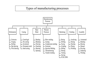
  • 3. Types of manufacturing processes Extrusion Forging Rolling Bar drawing Wiredrawing Deformation Centrifugal Die casting Investment Permanent mold Sand casting Casting Bending Blanking Drawing Punching Shearing Spinning Sheet Metal Blow molding Casting Compression molding Extrusion Injection Molding Thermoforming Transfer molding Polymer Processes Boring Drilling Facing Grinding Milling Planing Turning Sawing ECM, EDM Machining Anodizing Honing Painting Plating Polishing Finishing Automated Bonding Brazing Manual Riveting Soldering Welding Assembly Manufacturing Processes
  • 4. Casting since about 4000 BC… 4 Ancient Greece; bronze statue casting circa 450BC Iron works in early Europe, e.g. cast iron cannons from England circa 1543
  • 5. Casting • Foundry is a process of producing metal castings. • Casting is an operation of shaping metal by pouring it in the liquid state into a mold followed by solidification. • Casting is a process in which molten metal flows into a mold where it solidifies in the shape of the mold cavity. The part produced is also called casting. • In some cases casting is the only method of shaping a metal or alloy: when the alloy is not malleable and therefore it’s plastic deformation is not possible or when a large detail of complex shape is to be produced.
  • 6. Advantages • Complex shapes • Net-shape ability • Very large parts • Variety of metals • Mass production Disadvantages • Poor accuracy • Poor surface • Internal defects • Mechanical properties • Environmental impact Applications  Big parts: engine blocks and heads for automotive vehicles, wood burning stoves, machine frames, railway wheels, pipes, church bells, big statues, and pump housings  Small parts: dental crowns, jewelry, small statues, and frying pans Cameras
  • 7. Casting Processes • 1. Expendable mold processes Uses an expendable mold which must be destroyed to remove casting Mold materials: sand, plaster & ceramic • 2. Permanent mold processes Uses a permanent mold which can be used many times to produce many castings Mold materials :Made of metal
  • 8. Casting Processes Expendable mould Permanent mould Sand mould Gravity die casting Pressure die casting Centrifugal casting Continuous casting Investment mould
  • 9. Sand Casting • Sand casting, the most widely used casting process, utilizes expendable sand molds to form complex metal parts that can be made of nearly any alloy. • - has a low production rate. • The sand casting process involves the use of a furnace, metal, pattern, and sand mold.
  • 10. CASTING TERMINOLOGY • Pattern: It is the replica of the final object to be made.
  • 11. CASTING TERMINOLOGY •Core: A separate part of the mould, made of sand which is placed in mould to create openings and various shaped cavities in the castings.
  • 12. CASTING TERMINOLOGY • Flask(Mould box): A metal or wood frame/container, without fixed top or bottom which is used to create the mould.
  • 13. CASTING TERMINOLOGY • Mould: In sand casting, the primary piece of equipment is the mould, which contains several components. The mould is divided into two halves - the cope (upper half) and the drag (bottom half), which meet along a parting line. • Mould cavity: The mould cavity is formed by packing sand around the pattern in each half of the flask. The mould cavity is made with the help of pattern.
  • 14. CASTING TERMINOLOGY • Gating system: It consist of pouring basin,sprue,runner, gates, riser. It is used to feed the molten metal. • (1)Pouring basin(feeder:) A small funnel shaped cavity at the top of the mould into which the molten metal is poured. • (2)Sprue: The passage through which the molten metal, from the pouring basin, reaches the mold cavity. In many cases it controls the flow of metal into the mold.
  • 15. • (3)Runner: The channel through which the molten metal is carried from the sprue to the gate. • (4)Gate: A channel through which the molten metal enters the mold cavity. • (5)Riser: A column of molten metal placed in the mold to feed the castings as it shrinks and solidifies. Also known as feed head.
  • 19. Steps in Sand Casting
  • 20. Steps in Sand Casting
  • 21. Steps in Sand Casting 1 2 3 4 5 6 7 8 9 10 Fettling
  • 22. What is basic requirement for sand casting process…? • 1. Pattern. • 2. Core • 3. Gating system • 4. Sand casting • 5. Mold
  • 24. •It is the replica of the final object to be made. •Pattern is the solid form that is used to make mold cavity. •The quality of the castings produced depends on the design of the pattern, its material and construction. • One major requirement is that patterns (and therefore the mold cavity) must be oversized • (i) to account for shrinkage in cooling and solidification, and • (ii) to provide enough metal for the subsequence machining operation(s). I. PATTERN
  • 27. FACTORS EFFECTING SELECTION OF PATTERN MATERIAL 1. Number of castings to be produced. Metal pattern----- large in number. 2. Type of mold material used. 3. Kind of molding process. 4. Method of molding (hand or machine). 5. Degree of dimensional accuracy and surface finish required. 6. Minimum thickness required. 7. Shape, complexity and size of casting. 8. Cost of pattern and chances of repeat orders of the pattern
  • 28. COMMON PATTERN MATERIALS • The common materials used for making patterns are wood, metal, plastic, plaster, wax or mercury. Pattern properties are • Easily worked, shaped and joined • Light in weight • Strong, hard, durable etc • Resistance to wear and abrasion, chemical reaction • Dimensionally stable • Available at low cast Pattern Materials • Wood-pine (softwood), or mahogany (hardwood), • Metals and alloys • Plaster of Paris • Plastic and rubber • Wax and resins
  • 29. 1. Wood- shisham, kail, deodar, teak and mahogany. Advantages of wooden patterns 1 Wood can be easily worked. 2 It is light in weight. 3 It is easily available. 4 It is very cheap. 5 It is easy to join. 6 It is easy to obtain good surface finish. 7 Wooden laminated patterns are strong. 8 It can be easily repaired. Disadvantages 1 It is susceptible to moisture. 2 It tends to warp. 3 It wears out quickly due to sand abrasion. 4 It is weaker than metallic patterns.
  • 30. 2. Metal- cast iron, brass and bronzes and aluminum alloys. • i). Cast Iron Advantages • 1. It is cheap • 2. It is easy to file and fit • 3. It is strong • 4. It has good resistance against sand abrasion • 5. Good surface finish Disadvantages • 1 It is heavy • 2 It is brittle and hence it can be easily broken • 3 It may rust
  • 31. ii). Brasses and Bronzes Advantages • 1. Better surface finish than cast iron. • 2. Very thin sections can be easily casted. Disadvantages • 1. It is costly • 2. It is heavier than cast iron. iii). Aluminum Alloys Advantages • 1. Aluminum alloys pattern does not rust. • 2. They are easy to cast. • 3. They are light in weight. • 4. They can be easily machined. Disadvantages • 1. They can be damaged by sharp edges. • 2. They are softer than brass and cast iron. • 3. Their storing and transportation needs proper care.
  • 32. • Iv). White Metal (Alloy of Antimony, Copper and Lead) • Advantages • 1. It is best material for lining and stripping plates. • 2. It has low melting point around 260°C • 3. It can be cast into narrow cavities. • Disadvantages • 1. It is too soft. • 2. Its storing and transportation needs proper care • 3. It wears away by sand or sharp edges.
  • 33. 3. Plastic • Advantages • lighter, stronger, moisture and wear resistant, non sticky to molding sand, durable and they are not affected by the moisture of the molding sand. • Moreover they impart very smooth surface finish on the pattern surface. Disadvantages • These materials are somewhat fragile, less resistant to sudden loading and their section may need metal reinforcement. • The plastics used for this purpose are thermosetting resins. • Phenolic resin plastics are commonly used.
  • 34. 4. Plaster • The main advantages of plaster are that it has high compressive strength and is of high expansion setting type which compensate for the shrinkage allowance of the casting metal. • It is also preferred for production of small size intricate castings and making core boxes. • preferable for producing highly intricate casting.
  • 35. 5. Wax • The commonly used waxes are paraffin wax, shellac wax, bees- wax, cerasin wax, and micro-crystalline wax. • used in the process of investment casting where accuracy is linked with intricacy of the cast object.
  • 36. TYPES OF PATTERN 1. One piece or solid pattern 2. Two piece or split pattern 3. Cope and drag pattern 4. Three-piece or multi- piece pattern 5. Loose piece pattern 6. Match plate pattern 7. Follow board pattern 8. Gated pattern 9. Sweep pattern 10. Skeleton pattern 11. Segmental or part pattern
  • 37. 1. Loose pattern: • Loose pattern are patterns which are not connected to other patterns or mounted on a plate. Loose patterns may be further classified into: • 1. Solid or Single piece pattern • 2. Self core pattern • 3. Split patterns • 4. Loose piece pattern
  • 38. 1.Solid Pattern/single piece pattern • Solid pattern is made of single piece without joints, partings lines or loose pieces. It is the simplest form of the pattern. • It is an easy pattern to manufacture, but determining the parting line between cope and drag is more difficult for the foundry worker.
  • 39. 2. Self core patterns: • Self core type solid patterns are patterns having a hollow portion with straight draft which is used for producing its own core during moulding process itself. • This type of pattern eliminates the need for core box.
  • 40. 3. Split Pattern: • The split pattern is comprised of two separate parts that when put together will represent the geometry of the casting. • Split pattern is made in two pieces which are joined at the parting line by means of dowel pins. • The splitting at the parting line is done to facilitate the withdrawal of the pattern.
  • 41. 4. Match Plate Pattern: • -- high production. • In the match plate pattern, however, each of the parts are mounted on a plate. • The plates come together to assemble the pattern for the casting process. • - more proficient and makes alignment of the pattern in the mold quick and accurate.
  • 42. 5. Cope and Drag Pattern: • Each of the two halves are mounted on a separate plate for easy alignment of the pattern and mold. • The cope and drag pattern enables the cope section of the mold, and the drag section of the mold to be created separately and latter assembled before the pouring of the casting.
  • 43. 6. Shell patterns: • --used for piping work or for producing drainage fittings. • This pattern consists of a thin cylindrical or curved metal piece parted along the center line. • The two halves of the pattern are held in alignment by dowels.
  • 44. 6. Gated patterns: • Gated patterns are number of loose patterns connected with a gating system. • They are molded like a single pattern and withdrawn from the mould in one piece thus reducing moulding time. • Gated patterns are useful when a number of small castings are to be produced Eg. Investment casting
  • 45. 7. Sweep pattern • Sweep patterns are used for forming large circular moulds of symmetric kind by revolving a sweep attached to a spindle. • Actually a sweep is a template of wood or metal and is attached to the spindle at one edge and the other edge has a contour depending upon the desired shape of the mould. • The pivot end is attached to a stake of metal in the center of the mould.
  • 46. 8. Skeleton pattern • When only a small number of large and heavy castings are to be made, it is not economical to make a solid pattern. • In such cases, however, a skeleton pattern may be used. • This is a ribbed construction of wood which forms an outline of the pattern to be made. • This frame work is filled with loam sand and rammed. • The surplus sand is removed by stickle board. • For round shapes, the pattern is made in two halves which are joined with glue or by means of screws etc.
  • 47. 9. Three-piece or multi-piece pattern • Some patterns are of complicated kind in shape and hence can not be made in one or two pieces because of difficulty in withdrawing the pattern. • Therefore these patterns are made in either three pieces or in multi-pieces. • Multi molding flasks are needed to make mold from these patterns.
  • 48. 10. Segmental pattern • Patterns of this type are generally used for circular castings, for example wheel rim, gear blank etc. • Such patterns are sections of a pattern so arranged as to form a complete mould by being moved to form each section of the mould. • The movement of segmental pattern is guided by the use of a central pivot.
  • 49. 11. Follow board pattern • When the use of solid or split patterns becomes difficult, a contour corresponding to the exact shape of one half of the pattern is made in a wooden board, which is called a follow board and it acts as a molding board for the first molding operation
  • 50. PATTERN ALLOWANCES • The size of a pattern is never kept the same as that of the desired casting because of the fact that during cooling the casting is subjected to various effects and hence to compensate for these effects, corresponding allowances are given in the pattern. • These various allowances given to pattern can be enumerated as, • allowance for shrinkage, • allowance for machining, • allowance for draft, • allowance for rapping or shake, • allowance for distortion and • allowance for mould wall movement.
  • 51. 1. Shrinkage Allowance • In practice it is found that all common cast metals shrink a significant amount when they are cooled from the molten state. The total contraction in volume • 1. Liquid contraction, i.e. the contraction during the period in which the temperature of the liquid metal or alloy falls from the pouring temperature to the liquidus temperature. • 2. Contraction on cooling from the liquidus to the solidus temperature, i.e. solidifying contraction. • 3. Contraction that results there after until the temperature reaches the room temperature. This is known as solid contraction. • The first two of the above are taken care of by proper gating and risering. • Only the last one, i.e. the solid contraction is taken care by the pattern makers by giving a positive shrinkage allowance.
  • 52. • The contraction allowances for different metals and alloys such as • Cast Iron 10 mm/m. • Brass 16 mm/m, • Aluminium Alloys. 15 mm/m., • Steel 21 mm/m, • Lead 24 mm/m. • Copper 16mm/m. In fact, there is a special rule known as the pattern marks contraction rule / shrinkage rule in which the shrinkage of the casting metals is added.
  • 53. 2. Machining Allowance • It is a positive allowance given to compensate for the amount of material that is lost in machining or finishing the casting. • If this allowance is not given, the casting will become undersize after machining. • The amount of this allowance depends on the size of casting, methods of machining and the degree of finish. • the value varies from 3 mm. to 18 mm.
  • 54. 3. Draft or Taper Allowance • Taper allowance is also a positive allowance and is given on all the vertical surfaces of pattern so that its withdrawal becomes easier. • The normal amount of taper on the external surfaces varies from 10 mm to 20 mm/mt. On interior holes and recesses which are smaller in size, the taper should be around 60 mm/mt. These values are greatly affected by • the size of the pattern and the molding method. In machine molding its, value varies from 10 mm to 50 mm/mt.
  • 55. 4. Rapping or Shake Allowance • Actually by rapping, the external sections move outwards increasing the size and internal • sections move inwards decreasing the size. • This movement may be insignificant in the case of • small and medium size castings, but it is significant in the case of large castings. • This allowance is kept negative and hence the pattern is made slightly smaller in dimensions 0.5-1.0 mm.
  • 56. 5. Distortion Allowance • This allowance is applied to the castings which have the tendency to distort during cooling due to thermal stresses developed. • For example a casting in the form of U shape will contract at the closed end on cooling, while the open end will remain fixed in position. • Therefore, to avoid the distortion, the legs of U pattern must converge slightly so that the sides will remain parallel after cooling.
  • 58. II. Core • Cores serve to produce internal surfaces in castings, in some cases, they have to be supported by chaplets for more stable positioning. • For producing hallow casting. • The core is normally a disposable item that is destroyed to get it out of the piece. Eg. the use of cores is in the casting of engine blocks
  • 59. Definition of core:- Cores are compact mass of core sand that when placed in mould cavity at required location with proper alignment does not allow the molten metal to occupy space for solidification in that portion and hence help to produce hollowness in the casting.
  • 60. Types of core Cores are classified according to shape and position in the mold. 1. Horizontal core 2. Vertical core 3. Balanced core 4. Hanging and cover core –wire support 5. Wind up core- below or above parting line 6. Ram up core- before ramming 7. Kiss core - no core prints (seat)
  • 61. •Horizontal •Usually cylindrical, laid horizontally at parting plane •Core rest in seats provided by core print on pattern
  • 62. •Vertical •Both in cope and drag •Top and bottom provided with taper - alignment
  • 63. •Balanced •Opening on one side of casting •Only one core print •Core print is made large to balance the weight and sufficient support •Long core supported by chaplets
  • 64. •Cover Cover hanging from cope plus support at bottom in drag
  • 65. •Hanging •Core hangs from cope and no support at bottom of drag
  • 66. • Wing • When hole is required in casting above or below the parting line • Side of core is given sufficient amount of taper so core can be placed easily • Also called as drop core, tail core, chair or saddle core
  • 67. •Ram – up •Setting the core brfore mould is rammed • core details located in in-acessible position
  • 68. •Kiss Core •No core prints and no seta is available •Core is held between cope and drag simply by pressure of cope
  • 70. Fig. Vertical core Fig. Balancing core
  • 71. CORE MAKING • Core making basically is carried out in four stages namely • 1. core sand preparation, • 2. core making, • 3. core baking and • 4. core finishing.
  • 72. i. CORE sand characteristics / properties • It is special kind of molding sand. • Those considerations involves • (i) The cores are subjected to a very high temperature and hence the core sand should be highly refractory in nature • (ii) The permeability of the core sand must be sufficiently high as compared to that of the molding sands so as to allow the core gases to escape through the limited area of the core recesses generated by core prints • (iii) The core sand should not possess such materials which may produce gases while they come in contact with molten metal and • (iv) The core sand should be collapsible in nature, i.e. it should disintegrate after the metal solidifies, because this property will ease the cleaning of the casting.
  • 73. • The main constituents of the core sand are pure silica sand and a binder. • Silica sand is preferred because of its high refractoriness. • For higher values of permeability sands with coarse grain size distribution are used. • The main purpose of the core binder is to hold the grains together, impart strength and sufficient degree collapsibility. Core Material
  • 74. Commonly used binders in core making.. 1. Cereal binder It develops green strength, baked strength and collapsibility in core. The amount of these binders used varies from 0.2 to 2.2% by weight in the core sand. 2. Protein binder It is generally used to increase collapsibility property of core. 3. Thermo setting resin It is gaining popularity nowadays because it imparts high strength, collapsibility to core sand and it also evolve minimum amount of mold and core gases which may produce defects in the casting. The most common binders under this group are phenol formaldehyde and urea formaldehyde. 4. Sulphite binder Sulphite binder is also sometimes used in core but along with certain amount of clay. 5. Dextrin It is commonly added in core sand for increasing collapsibility and baked strength of core
  • 75. 1.Core blowing machines • The basic principle of core blowing machine comprises of filling the core sand into the core box by using compressed air. • The velocity of the compressed air is kept high to obtain a high velocity of core sand particles, thus ensuring their deposit in the remote corners the core box. • On entering the core sand with high kinetic energy, the shaping and ramming of core is carried out simultaneously in the core box. ii. The process of core making is basically mechanized using core blowing, core ramming and core drawing machines
  • 76. 2. Core ramming machines • Cores can also be prepared by ramming core sands in the core boxes by machines based on the principles of squeezing, jolting and slinging. • Out of these three machines, jolting and slinging are more common for core making. 3. Core drawing machines • The core drawing is preferred when the core boxes have deep draws. After ramming sand in it, the core box is placed on a core plate supported on the machine bed. • A rapping action on the core box is produced by a vibrating vertical plate. • This rapping action helps in drawing off the core from the core box. • After rapping, the core box, the core is pulled up thus leaving the core on the core plate. • The drawn core is then baked further before its use in mold cavity to produce hollowness in the casting.
  • 77. iii. Core baking • Once the cores are prepared, they will be baked in a baking ovens or furnaces. • The main purpose of baking is to drive away the moisture and hard en the binder, thereby giving strength to the core. Dielectric bakers • After baking of cores, they are smoothened using dextrin and water soluble binders.
  • 78. Type of cores 1. GREEN SAND CORES • Green sand cores are made by green sand containing moist condition about 5% water and 15- 30 % clay. • It imparts very good permeability to core and thus avoids defects like shrinkage or voids in the casting. Green sand cores are not dried. • They are poured in green condition and are generally preferred for simple, small and medium castings. • Such cores possess less strength in comparison to dry sand cores and hence cannot be stored for longer period. 2. DRY SAND CORES • Dry sand cores are produced by drying the green sand cores to about 110°C. • These cores possess high strength rigidity and also good thermal stability. • These cores can be stored for long period and are more stable than green sand core. They are used for large castings. • They also produce good surface finish in comparison to green sand cores.
  • 79. Core Box • Any kind of hollowness in form of holes and recesses in castings is obtained by the use of cores. • Cores are made by means of core boxes comprising of either single or in two parts. • Core boxes are generally made of wood or metal and are of several types. • The main types of core box are • half core box, • dump core box, • split core box, • strickle core box, • right and left hand core box and • loose piece core box.
  • 80. 1. Half core box • This is the most common type of core box. The two identical halves of a symmetrical core prepared in the half core box. • Two halves of cores are pasted or cemented together after baking to form a complete core.
  • 81. 2. Dump core box • Dump core box is similar in construction to half core box. • The cores produced do not require pasting, rather they are complete by themselves. • If the core produced is in the shape of a slab, then it is called as a slab box or a rectangular box. • A dump core-box is used to prepare complete core in it. Generally cylindrical and rectangular cores are prepared in these boxes.
  • 82. 3. Split core box • Split core boxes are made in two parts. • They form the complete core by only one ramming. • The two parts of core boxes are held in position by means of clamps and their alignment is maintained by means of dowel pins and thus core is produced.
  • 83. 4. Right and left hand core box • Some times the cores are not symmetrical about the center line. In such cases, right and left hand core boxes are used. The two halves of a core made in the same core box are not identical and they cannot be pasted together. 5. Strickle core box • This type of core box is used when a core with an irregular shape is desired. The required shape is achieved by striking oft the core sand from the top of the core box with a wooden piece, called as strickle board. The strickle board has the same contour as that of the required core. 6. Loose piece core box • Loose piece core boxes are highly suitable for making cores where provision for bosses, hubs etc. is required. In such cases, the loose pieces may be located by dowels, nails and dovetails etc. In certain cases, with the help of loose pieces, a single core box can be made to generate both halves of the right-left core.
  • 84. Color codification for patterns and core boxes • There is no set or accepted standard for representing of various surfaces of pattern and core boxes by different colors. • The American practice is the most popular. • In this practice, the color identification is as follows. surfaces color Unfinished Surfaces black Machined surfaces red Core prints yellow Seats for loose pieces red stripes on yellow background Stop-offs black stripes on yellow base
  • 85. CORE PRINTS • When a hole blind or through is needed in the casting, a core is placed in the mould cavity to produce the same. • The core has to be properly located or positioned in the mould cavity on pre-formed recesses or impressions in the sand. • To form these recesses or impressions for generating seat for placement of core, extra projections are added on the pattern surface at proper places. • These extra projections on the pattern (used for producing recesses in the mould for placement of cores at that location) are known as core prints.
  • 86. • The core is placed in the metal casting after the removal of the pattern.
  • 87. III. Gating System • In order for this mold to be functional to manufacture a casting, in addition to the impression of the part, the mold cavity will also need to include a gating system. • Sometimes the gating system will be cut by hand or in more adept manufacturing procedures the gating system will be incorporated into the pattern along with the part. • Basically a gating system functions during the metal casting operation to facilitate the flow of the molten material into the mold cavity.
  • 91. Pouring Basin: • This is where the molten metal employed to manufacture the part enters the mold. The pouring basin should have a projection with a radius around it to reduce turbulence. Down Sprue: • From the pouring basin the molten metal for the casting travels through the down sprue. This should be tapered so its cross-section is reduced as it goes downward. Sprue Base: • The down sprue ends at the sprue base. It is here that the casting's inner cavity begins.
  • 92. Gate • It is a small passage or channel being cut by gate cutter which connect runner with the mould cavity and through which molten metal flows to fill the mould cavity. • It feeds the liquid metal to the casting at the rate consistent with the rate of solidification. Choke • It is that part of the gating system which possesses smallest cross- section area. • In choked system, gate serves as a choke, but in free gating system sprue serves as a choke.
  • 93. Chaplets • Chaplets are metal distance pieces inserted in a mould either to prevent shifting of mould or locate core surfaces. • The distances pieces in form of chaplets are made of parent metal of which the casting is. These are placed in mould cavity suitably which positions core and to give extra support to core and mould surfaces. • Its main objective is to impart good alignment of mould and core surfaces and to achieve directional solidification. • When the molten metal is poured in the mould cavity, the chaplet melts and fuses itself along with molten metal during solidification and thus forms a part of the cast material.
  • 94. Chills • At that particular position, the special mould surface for fast extraction of heat is to be made. • The fast heat extracting metallic materials known as chills will be incorporated separately along with sand mould surface during molding. • Thus, the main function of chill is to provide a hard surface at a localized place in • the casting by way of special and fast solidification.
  • 95. Runners: • Runners are passages that distribute the liquid metal to the different areas inside the mold. Main Cavity: • The impression of the actual part to be cast is often referred to as the main cavity. Vents: • Vents help to assist in the escape of gases that are expelled from the molten metal during the solidification phase of the metal casting process.
  • 96. Risers: • Risers are reservoirs of molten material. They feed this material to sections of the mold to compensate for shrinkage as the casting solidifies. There are different classifications for risers. Top Risers: Risers that feed the metal casting from the top. Side Risers: Risers that feed the metal casting from the side. Blind Risers: Risers that are completely contained within the mold. Open Risers: Risers that are open at the top to the outside environment. Figure . Illustrates the difference between top risers and side risers.
  • 97. Why Riser? • The shrinkage occurs in three stages, 1. When temperature of liquid metal drops from pouring to zero temperature 2. When the metal changes from liquid to solid state, and 3. When the temperature of solid phase drops from freezing to room temperature • The shrinkage for stage 3 is compensated by providing shrinkage allowance on pattern, while the shrinkage during stages 1 and 2 are compensated by providing risers. • The riser should solidify in the last otherwise liquid metal will start flowing from casting to riser. It should promote directional solidification. The shape, size and location of the risers are important considerations in casting design
  • 98. IV. MOLDING SAND • The general sources of receiving molding sands are the beds of sea, rivers, lakes, granular elements of rocks, and deserts. • The common sources of molding sands available in India are as follows: • 1 Batala sand ( Punjab) • 2 Ganges sand (Uttar Pradesh) • 3 Oyaria sand (Bihar) • 4 Damodar and Barakar sands (Bengal- Bihar Border) • 5 Londha sand (Bombay) • 6 Gigatamannu sand (Andhra Pradesh) and • 7 Avadi and Veeriyambakam sand (Madras)
  • 99. • Molding sands may be of two types namely natural or synthetic. • Natural molding sands contain sufficient binder. • Whereas synthetic molding sands are prepared artificially using basic sand molding constituents (silica sand in 88-92%, binder 6-12%, water or moisture content 3-6%) and other additives in proper proportion by weight with perfect mixing and mulling in suitable equipments.
  • 100. CONSTITUENTS OF MOLDING SAND • The main constituents of molding sand involve silica sand, binder, moisture content and additives. 1. Silica sand • Silica sand in form of granular quarts is the main constituent of molding sand having enough refractoriness which can impart strength, stability and permeability to molding and core sand. • But along with silica small amounts of iron oxide, alumina, lime stone, magnesia, soda and potash are present as impurities. • The chemical composition of silica sand gives an idea of the impurities like lime, magnesia, alkalis etc. present. • The presence of excessive amounts of iron oxide, alkali oxides and lime can lower the fusion point to a considerable extent which is undesirable. • The silica sand can be specified according to the size (small, medium and large silica sand grain) and the shape (angular, sub-angular and rounded).
  • 101. 2. Binder • In general, the binders can be either inorganic or organic substance. • The inorganic group includes clay sodium silicate and port land cement etc. In foundry shop, the clay acts as binder which may be Kaolonite, Ball Clay, Fire Clay, Limonite, Fuller’s earth and Bentonite. • Binders included in the organic group are dextrin, molasses, cereal binders, linseed oil and resins like phenol formaldehyde, urea formaldehyde etc. • Organic binders are mostly used for core making. • Among all the above binders, the bentonite variety of clay is the most common. • However, this clay alone can not develop bonds among sand grins without the presence of moisture in molding sand and core sand.
  • 102. 3. Moisture • The amount of moisture content in the molding sand varies generally between 2 to 8 percent. • This amount is added to the mixture of clay and silica sand for developing bonds. • This is the amount of water required to fill the pores between the particles of clay without separating them. • This amount of water is held rigidly by the clay and is mainly responsible for developing the strength in the sand. • The effect of clay and water decreases permeability with increasing clay and moisture content. • The green compressive strength first increases with the increase in clay content, but after a certain value, it starts decreasing.
  • 103. 4 Additives • Additives are the materials generally added to the molding and core sand mixture to develop some special property in the sand. 4.1 Coal dust • Coal dust is added mainly for producing a reducing atmosphere during casting. • This reducing atmosphere results in any oxygen in the poles becoming chemically bound so that it cannot oxidize the metal. • It is usually added in the molding sands for making molds for production of grey iron and malleable cast iron castings.
  • 104. 4.2 Corn flour • It belongs to the starch family of carbohydrates and is used to increase the collapsibility of the molding and core sand. • It is completely volatilized by heat in the mould, thereby leaving space between the sand grains. • This allows free movement of sand grains, which finally gives rise to mould wall movement and decreases the mold expansion and hence defects in castings. • Corn sand if added to molding sand and core sand improves significantly strength of the mold and core.
  • 105. 4.3 Dextrin • Dextrin belongs to starch family of carbohydrates that behaves also in a manner similar to that of the corn flour. It increases dry strength of the molds. 4.4 Sea coal • Sea coal is the fine powdered bituminous coal which positions its place among the pores of the silica sand grains in molding sand and core sand. • When heated, it changes to coke which fills the pores and is unaffected by water: Because to this, the sand grains become restricted and cannot move into a dense packing pattern. • Thus, sea coal reduces the mould wall movement and the permeability in mold and core sand and hence makes the mold and core surface clean and smooth.
  • 106. 4.5 Pitch • It is distilled form of soft coal. It can be added from 0.02 % to 2% in mold and core sand. • It enhances hot strengths, surface finish on mold surfaces and behaves exactly in a manner similar to that of sea coal. 4.6 Wood flour • This is a fibrous material mixed with a granular material like sand; its relatively long thin fibers prevent the sand grains from making contact with one another. • It can be added from 0.05 % to 2% in mold and core sand. • It also increases collapsibility of both of mold and core. 4.7 Silica flour • It is called as pulverized silica and it can be easily added up to 3% which increases the hot strength and finish on the surfaces of the molds and cores. It also reduces metal penetration in the walls of the molds and cores.
  • 107. Moulding Sand/ Foundry Sand • Moulding Sands: • Most sand casting operations use Silica sand (SiO2). Usually sand used to manufacture a mould for the casting process is held together by a mixture of water and clay. A typical mixture by volume could be 89% sand, 4% water, 7% clay.
  • 108. Types Of Moulding Sands • Classification of moulding sands: 1. Green sand: • It is sand used in the wet condition for making the mould. It is mixture of silica sand with 15-25 per cent clay and 6-8 per cent water • As explained earlier green sand moulds are not dried and metal is poured in them in the wet condition • Being damp the sand can be easily worked with hand to give it any desired shape This sand is used for producing small to medium sized moulds which are not very complex
  • 109. 2. Dry sand: • Dry sand is the green sand that has been dried or baked after preparing the mould. • Drying sand gives strength to the mould so that it can be used for larger castings
  • 110. • 3. Loam sand: • Loam sand is sand containing up to 50 % clay which has been worked to the consistency of builder mortar. • This sand is used for loam sand moulds for making very heavy castings usually with the help of sweeps and skeleton patterns.
  • 111. 4. Parting sand: • This sand is used during making of the mould to ensure that green sand does not stick to the pattern and the cope and drug parts can be easily separated for removing the pattern without causing any damage to the mould. • Parting sand consists of fine grained clay free dried silica sand, sea sand or burnt sand with some parting compounds. • The parting compounds used include charcoal, ground bone and limestone, groundnut shells, talc and calcium phosphate.
  • 112. 5. Facing sand: • Facing sand is the sand which covers the pattern all around it. The remaining box is filled with ordinary floor sand. • Facing sand forms the face of the mould and comes in direct contact with the molten metal when it is poured. • High strength and refractoriness are required for this sand. • It is made of silica sand and clay without the addition of any used sand. • Graphite, mollases, plumbago etc. may be added to the facing sand. Thickness of the sand layer varies from 20 to 30 mm.
  • 113. 6. Backing sand: • Backing sand is the bulk of the sand used to back up the facing sand and to fill up the volume of the flask. • It consists mainly of old, repeatedly used moulding sand which is generally black in colour due to addition of coal dust and burning on contact with hot metal. • Because of the colour backing sand is also sometimes called black sand. • The main purpose for the use of backing sand is to reduce the cost of moulding.
  • 114. 7. System sand: • This is the sand used in mechanized foundries for filling the entire flask. • No separate facing sand in used in a mechanized foundry. • Sand, cleaned and reactivated by the addition of water and binders is used to fill the flask. Because of the absence of any fresh sand, system sand must have more strength, permeability and refractoriness compared to backing sand.
  • 115. 8. Core sand: • Core sand is the sand used for making cores. This is silica sand mixed with core oil. That is why it is also called oil sand. • The core oil consists of linseed oil, resin, light mineral oil with some binders. • For larger cores, sometimes pitch or flour and water may also be used to save on cost.
  • 116. Important characteristics of sand are: • 1. These sands are refractory in nature and can withstand temperature of the metal being poured, without fusing. • 2. The moulding sands do not chemically react or combine with molten metal and can therefore be used repeatedly. • 3. The sands have a high degree of permeability and thus allow the gases formed during pouring to escape. • 4. The strength, permeability and hardness of the sand mix can be varied by changing the structure or ingredients of sand.
  • 117. Properties of moulding sands: 1. Strength 2. Permeability 3. Grain Size and Shape 4. Thermal stability 5. Refractoriness 6. Flow ability 7. Sand Texture 8. Collapsibility 9. Adhesiveness 10. Reusability 11. Easy of preparation and control 12. Conductivity
  • 118. Strength: • The sand should have adequate strength in its green, dry and hot states • Green strength is the strength of sand in the wet state and is required for making possible to prepare and handle the mould. • If the metal is poured into a green mould the sand adjacent to the metal dries and in the dry state it should have strength to resist erosion and the pressure of metal. • The strength of the sand that has been dried or basked is called dry strength. • At the time of pouring the molten metal the mould must be able to withstand flow and pressure of the metal at high temperature otherwise the mould may enlarge, crack, get washed or break
  • 119. Strength of the moulding sand depends on: • 1. Grain size and shape • 2. Moisture content • 3. Density of sand after ramming • The strength of the mould increases with a decrease of grain size and an increase of clay content and density after ramming. • The strength also goes down if moisture content is higher than an optimum value.
  • 120. 2. Permeability: • The moulding sand must be sufficiently porous to allow the dissolved gases, which are evolved when the metal freezes or moisture present or generated within the moulds to be removed freely when the moulds are poured. • This property of sand is called porosity or permeability.
  • 121. 3. Grain size and shape: • ·The size and shape of the grains in the sand determine the application in various types of foundry. These are three different sizes of sand grains. • 1. Fine • 2. Medium • 3. Coarse • Fine sand is used for small and intricate castings. • Medium sand is used for benchmark and light floor works. • If the size of casting is larger coarse sand is used • Sand having fine, rounded grains can be closely packed and forms a smooth surface. Although fine-grained sand enhances mould strength.
  • 122. 4. Thermal stability: • The sand adjacent to the metal is suddenly heated and undergoes expansion. • If the mould wall is not dimensionally stable under rapid heating, cracks, buckling and flacking off sand may occur.
  • 123. 5. Refractoriness: • Refractoriness is the property of withstanding the high temperature condition moulding sand with low refractoriness may burn on to the casting. • It is the ability of the moulding material to resist the temperature of the liquid metal to be poured so that it does not get fused with the metal. • The refractoriness of the Silica sand is highest.
  • 124. 6. Flowability: • Flowability or plasticity is the property of the sand to respond to the moulding process so that when rammed it will flow all around the pattern and take the desired mould shape. High flowability of sand is desirable for the sand to get compacted to a uniform density and to get good impression of the pattern in the mould. Flowability is also very important in machine moulding ·Flowability of sand increases as clay and water content are increased.
  • 125. 7. Sand texture: • As mentioned earlier the texture of sand is defined by its grain size and grain size distribution. • The texture chosen for an application should allow the required porosity, provide enough strength and produce the desired surface finish on the casting. 8. Collapsibility: • The moulding sand should collapse during the contraction of the solidified casting it does not provide any resistance, which may result in cracks in the castings. • Besides these specific properties the moulding material should be cheap, reusable and should have good thermal conductivity
  • 126. 9. Adhesiveness & Cohesiveness: • The sand particles must be capable of adhering to another body, then only the sand should be easily attach itself with the sides of the moulding box and give easy of lifting and turning the box when filled with the stand. Cohesiveness
  • 127. 10. Reusability: • Since large quantities of sand are used in a foundry it is very important that the sand be reusable otherwise apart from cost it will create disposal problems 11. Easy of preparation and control: • Sand should lend itself to easy preparation and control by mechanical equipment 12. Conductivity: • Sand should have enough conductivity to permit removal of heat from the castings.
  • 128. • 1. Moisture content test • 2. Clay content test • 3. Grain fitness test • 4. Permeability test • 5. Strength test • 6. Refractoriness test • 7. Mould hardness test 1. Moisture content Test 2. Clay content Test 3. Chemical composition of sand 4. Grain shape and surface texture of sand. 5. Grain size distribution of sand 6. Specific surface of sand grains 7. Water absorption capacity of sand 8. Refractoriness of sand 9. Strength Test 10. Permeability Test 11. Flowability Test 12. Shatter index Test 13. Mould hardness Test. SAND TESTING METHODS AND SAND TESTING EQUIPMENT
  • 129. 1. Moisture content test: • Moisture is the property of the moulding sand it is defined as the amount of water present in the moulding sand. Low moisture content in the moulding sand does not develop strength properties. High moisture content decreases permeability.
  • 130. Procedures are: • 1. 20 to 50 gms of prepared sand is placed in the pan and is heated by an infrared heater bulb for 2 to 3 minutes. • 2. The moisture in the moulding sand is thus evaporated. • 3. Moulding sand is taken out of the pan and reweighed. • 4. The percentage of moisture can be calculated from the difference in the weights, of the original moist and the consequently dried sand samples.
  • 131. • Percentage of moisture content = (W1-W2)/(W1) % Where, W1-Weight of the sand before drying, W2-Weight of the sand after drying.
  • 132. 2. Clay content test • Clay influences strength, permeability and other moulding properties. It is responsible for bonding sand particles together.
  • 133. Procedures are: • 1. Small quantity of prepared moulding sand was dried • 2. Separate 50 gms of dry moulding sand and transfer wash bottle. • 3. Add 475cc of distilled water + 25cc of a 3% NaOH. • 4. Agitate this mixture about 10 minutes with the help of sand stirrer. • 5. Fill the wash bottle with water up to the marker. • 6. After the sand etc., has settled for about 10 minutes, Siphon out the water from the wash bottle. • 7. Dry the settled down sand. • 8. The clay content can be determined from the difference in weights of the initial and final sand samples. Percentage of clay content = (W1-W2)/(W1) * 100 Where, • W1-Weight of the sand before drying, • W2-Weight of the sand after drying.
  • 134. 3. Grain fitness test: • The grain size, distribution, grain fitness are determined with the help of the fitness testing of moulding sands. • The apparatus consists of a number of standard sieves mounted one above the other, on a power driven shaker. • The shaker vibrates the sieves and the sand placed on the top sieve gets screened and collects on different sieves depending upon the various sizes of grains present in the moulding sand. • The top sieve is coarsest and the bottom-most sieve is the finest of all the sieves. In between sieve are placed in order of fineness from top to bottom.
  • 135. • Procedures are: • 1. Sample of dry sand (clay removed sand) placed in the upper sieve • 2. Sand is vibrated for definite period • 3. The amount of same retained on each sieve is weighted. • 4. Percentage distribution of grain is computed.
  • 136. 3. Permeability test: • The quantity of air that will pass through a standard specimen of the sand at a particular pressure condition is called the permeability of the sand. • Following are the major parts of the permeability test equipment: • 1. An inverted bell jar, which floats in a water. • 2. Specimen tube, for the purpose of hold the equipment • 3. A manometer (measure the air pressure)
  • 139. Steps involved are: • 1. The air (2000cc volume) held in the bell jar is forced to pass through the sand specimen. • 2. At this time air entering the specimen equal to the air escaped through the specimen • 3. Take the pressure reading in the manometer. • 4. Note the time required for 2000cc of air to pass the sand • 5. Calculate the permeability number • 6. Permeability number (N) = ((V x H) / (A x P x T)) • Where, • V-Volume of air (cc) • H-Height of the specimen (mm) • A-Area of the specimen (mm2) • P-Air pressure (gm / cm2) • T-Time taken by the air to pass through the sand (seconds)
  • 140. Strength test: • Measurements of strength of moulding sands can be carried out on the universal sand strength testing machine. The strength can be measured in compression, shear and tension. • The sands that could be tested are green sand, dry sand or core sand. The compression and shear test involve the standard cylindrical specimen that was used for the permeability test. Steps involved are: 1. Specimen is held between the grips 2. Apply the hydraulic pressure by rotating the hand wheel 3. Taking the deformation use of the indicators.
  • 141. Refractoriness test • The refractoriness is used to measure the ability of the sand to withstand the higher temperature. Steps involved are: 1. Prepare a cylindrical specimen of sand 2. Heating the specimen at 1500 C for 2 hours 3. Observe the changes in dimension and appearance 4. If the sand is good, it retains specimen share and shows very little expansion. If the sand is poor, specimen will shrink and distort.
  • 142. Mould hardness test • Hardness of the mould surface can be tested with the help of an “indentation hardness tester”. It consists of indicator, spring loaded spherical indenter. The spherical indenter is penetrates into the mould surface at the time of testing. The depth of penetration w.r.t. the flat reference surface of the tester. Mould hardness number = ((P) / (D – (D2-d2)) Where, P- Applied Force (N) D- Diameter of the indenter (mm) d- Diameter of the indentation (mm)
  • 143. Advantages and disadvantages of sand casting • Advantages of sand casting • Low cost of mold materials and equipment. • Large casting dimensions may be obtained. • Wide variety of metals and alloys (ferrous and non-ferrous) may be cast (including high melting point metals). • Disadvantages of sand casting • Rough surface. • Poor dimensional accuracy. • High machining tolerances. • Coarse Grain structure. • Limited wall thickness: not higher than 0.1”-0.2” (2.5-5 mm).
  • 144. Advantages: Can produce very large parts Can form complex shapes Many material options Low tooling and equipment cost Scrap can be recycled Short lead time possible Disadvantages: Poor material strength High porosity possible Poor surface finish and tolerance Seondary machining often required Low production rate High labor cost Applications: Engine blocks and manifolds, machine bases, gears, pulleys, crankshafts, connecting rods, and propellers, cylinder heads, and transmission cases
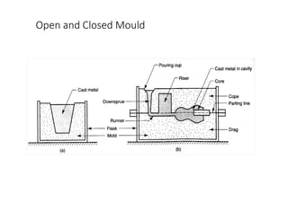
  • 145. V. The Mold A typical mold is shown in figure •The pattern is placed in the mold and the mold material is packed around it. • The mold contains two parts, the drag (bottom), and the cope (top). •The parting line between the cope and drag allows for the mold to be opened and the pattern to be removed once the impression has been made. •For some moulds additional intermediate boxes called “Cheeks” may be required.
  • 146. Mold (used in us ) / Mould ( used in Britain et al.) • A mold is formed into the geometric shape of a desired part. • Molten metal is then poured into the mold, the mold holds this material in shape as it solidifies. A metal casting is created. • Molds can be classified as either open or closed. • A open mold is a container, like a cup, that has only the shape of the desired part. • The molten material is poured directly into the mold cavity which is exposed to the open environment.
  • 147. Open and Closed Mould
  • 148. • Two main branches of methods can be distinguished by the basic nature of the mold they employ. • There is expendable mold casting and permanent mold casting. •Expendable Mold Can produce one metal casting only •Made of sand, plaster, or other similar material. Binders used to help material hold its form. •Mold that metal solidifies in must be destroyed to remove casting •More intricate geometries are possible for casting •Permanent Mold Can manufacture many metal castings •Usually made of metal or sometimes a refractory ceramic •Mold has sections that can open or close permitting removal of the casting •Need to open mold limits part shapes
  • 149. Mould Making • Making a mould properly means a casting half done. • A sand mould is formed by packing sand into each half of the mould. • The sand is packed around the pattern, which is a replica of the external shape of the casting. • When the pattern is removed, the cavity that will form the casting remains. • Any internal features of the casting that cannot be formed by the pattern are formed by separate cores which are made of sand prior to the formation of the mould.
  • 150. Characteristics of Mold • 1. The mould should be strong enough to resist erosion by the flow of the metal and to take the weight of the metal. • 2. The mould material should not produce too much of gases as the gases may enter the mould cavity and get entrapped with metal or violently boil out the metal. • 3. The mould should be made in such a way that gases generated are vented out of the mould. • 4. The mould should be refractory enough to withstand the high temperature of liquid metal. • 5. The cores should be collapsible enough to permit contraction of the metal after solidification. • 6. Flow should be laminar i.e. smooth flow • 7. There should be a proper riser system in the mould to provide sufficient extra metal to account for the liquid and solidification shrinkage. • 8. The mould material and moulding process should be such that cleaning of castings is facilitated.
  • 151. Molding Tools 1.Mallet: • It is a mallet to loosen the pattern in the mould by striking slightly, so that it can be withdrawn without damaging the mould
  • 152. • 2. Gate cutter: • It is a metal piece to the gate the opening that connects tee sprue with the mould cavity. (sleek)
  • 153. 3. Rapping plate (or) Lifting plate: • It is used to facilitate shaking and lifting large pattern from the mold.
  • 154. 4. Spirit level: • It is used to check that the sand bed, moulding box or table of moulding machine is horizontal.
  • 155. • 5. Clamps: • Clamps are used to hold the cope and drag of the complete mould together so that the cope may not float or rise when the molten metal is poured into the mould.
  • 156. 6. Moulding box: • Sand moulds are prepared specially constructed boxes called the moulding boxes or flasks. The function and construction of a molding box have already been described. Moulding flasks
  • 157. 7.Shovel: • It is just like rectangular pan fitted with a handle. It is used for mixing the moulding sand and for moving it from one place to the other.
  • 158. 8. Riddle: • It is used for removing foreign materials like nails, shot metal splinters of wood etc from the moulding sand.
  • 159. 9. Rammer: • It is a wooden tool used for ramming or packing the sand in the mould. Rammers are made in different shapes.
  • 160. 10. Strike-off bar: • It is a cast iron or wrought iron bar with a true straight edge. It is used to remove the surplus sand from the mould after the ramming has been completed.
  • 161. 11. Vent wire: • It is a mild steel wire used for making vents or openings in the mould.
  • 162. 12. Lifter: • It is a metal piece used for patching deep section of the mould and removing loose sand from pockets of the mould. 13. Slick: • Different types of slicks are used for repairing and finishing moulds. 14. Trowel: It contains of a flat and thick metal sheet with upwards projected handle at one end. It is used for making joints and finishing flat surface of a mould. 15. Swab: It is made of flax or hemp. It is used for applying water to the mould around the edge of the pattern.
  • 163. Moulding Machines • Moulding processes may be classified as hand moulding or machine moulding according to whether the mould is prepared by hand tools or with the aid of some moulding machine. • Hand moulding is generally found to be economical when the castings are required in a small number. • The major functions of molding machines involves ramming of molding sand, rolling over or inverting the mould, rapping the pattern and withdrawing the pattern from the mould. • Most of the molding machines perform a combination of two or more of functions.
  • 164. Types of Moulding machine: 1. Hand Operated molding machine a. Pattern draw type b. Pattern draw and Squeeze type c. Pin Lift type machine d. Roll Over type machine 2. Power operated Molding Machine a. Squeeze machine b. Jolt machine c. Jolt squeeze machine d. Jolt squeeze roll over pattern draw machine e. Sand Slinger
  • 165. Squeezer •1.table 2. pattern 3. flask. 4.Sand frame 5. platen 6. squeezer head. 7. frame
  • 166. Squeezer •Molding sand squeezed between machine table and overhead squeeze board •Pneumatic or hydraulic •Top squeezing •Bottom squeezing •Limitation- sand is packed more densely on top of mould •Density deceases uniformly with depth •At parting plane density is lowest •Restricted to molds up to 150 mm depth
  • 167. Jolt machine •1.table.3.patern and flask.8. plunger.9 hose.10. channel. •11. opening •12. guide cylinder •13. springs
  • 169. •Flask is filled with moulding sand •Table supporting flask is raised and dropped in succession •Due to sudden change in inertia – sand gets packed and rammed •Action of raising and sudden dropping – jolt •Drawback – sand is rammed hardest at parting plane sand remains les dense at tops •Preferred fro horizontal surfaces
  • 170. Jolt squeeze machine • Jolting action to consolodate sand on face of pattern • Squeezing – desired density throughout mass of sand • Mold with maximum hardness,unform ramming
  • 171. Sand slinger •Overhead impellar head 1. housing. 2. blade 3. opening 4. outlet •Conveyor buckets Slinging – consolidation and ramming due to impact of sand which falls at very high velocity Rate – 500 to 2000kg per min. Mold of adequate strength , hardness
  • 173. 5. Pattern draw machines • These machines enable easy withdrawal of patterns from the molds. • They can be of the kind of stripping plate type and pin lift or push off type. • The pattern is drawn through the stripping plate either by raising the stripping plate and the mould up and keeping the pattern stationary or by keeping the stripping plate and mould stationary and moving the pattern supporting ram downwards along with the pattern and pattern plate. • A suitable mechanism can be incorporated in the machine for these movements.
  • 174. •6. stripping pins •1.pattern, 3. pattern plate, table 5, molding box 2 •4. stripping plate between patern plate and flask
  • 175. 6 Roll-over machine • The pattern is mounted on a plate which is secured to the roll-over frame. • The platen of the machine can be moved up and down. • For preparation of the mould, the roll-over frame is clamped in position with the pattern facing upward. • Molding box is placed over the pattern plate and clamped properly. • Molding sand is then filled in it and rammed by hand and the extra molding sand is struck off and molding board placed over the box and clamped to it.
  • 176. •Turn over •Flask together with work table rotates 1800 and pin 6 lifts table with pattern •Pins 6
  • 178. Ladles • Moving molten metal from melting furnace to mold is sometimes done using crucibles • More often, transfer is accomplished by ladles Figure 11.21 Two common types of ladles: (a) crane ladle, and (b) two-man ladle. ©2007 John Wiley & Sons, Inc. M P Groover, Fundamentals of Modern Manufacturing 3/e
  • 179. The casting process ( Special Casting process) 1 - Expendable mold casting (sand, plastic, shell, and investment (lost-wax technique) mouldings.) 2 - Nonexpendable mold casting (permanent, die, centrifugal, and continuous casting). Classification of die casting: (a)Gravity Die Casting (also called permanent mould process) (b)Pressure Die Casting
  • 181. Precision or investment casting (lost wax casting) • Investment (lost wax) casting is a method of precision casting complex near-net-shape details using replication of wax patterns. • Precision or investment casting employed techniques that enable very smooth highly accurate castings to be made from both ferrous and non-ferrous alloys • The process is useful in casting unmachinable alloys and radioactive metals. • In investment casting, the pattern is made of wax, which melts after making the mold to produce the mold cavity.
  • 183. Ceramic slurry materials Mullite: Al2O3 44-48%, SiO2 47-51%, Fe2O3 max. 1%, TiO2 max. 1%. Zircon flour. Binders: Colloidal Silica SiO2 25-45%, Na2O max.1% in distilled water; sodium silicate NaO*nSiO2*mH2O; ethyl silicate Si(OC2H5)4.
  • 185. Investment casting process • The investment casting process uses expendable patterns made of investment casting wax. • The wax patterns are commonly prepared by injection molding technology which involves injection of wax into a prefabricated die having the same geometry of the cavity as the desired cast part. • The wax patterns are then attached to a gating system (a set of channels through which a molten metal flows to the mold cavity). • The next stage is the shell building - the wax assembly is immersed into refractory ceramic slurry of hardening mixtures followed by drying. This operation is repeatedly carried out resulting in formation of a solid ceramic shell of 1/4” -3/8” (6mm – 9mm) thick. • The next stage is dewax. At this stage the assembly is heated in an autoclave where the most of the wax is melted out. This operation is followed by burning out the residual wax in a furnace. • The mold is then preheated to 1830°F (1000°C). Now the mold is ready for filling with a molten metal. • Casting stage is conventional operation involving pouring a molten metal into the shell through the gating system. • After the metal has solidified and cooled to a desired temperature, the shell is broken and the castings are cut away from the gates and sprue. • The last stage is finishing carried out by sandblasting or machining.
  • 186. Advantages and disadvantages of investment casting Advantages: • Excellent surface finish. • Tight dimensional tolerances. • Complex and intricate shapes may be produced. • Capability to cast thin walls. • Wide variety of metals and alloys (ferrous and non-ferrous) may be cast. • Draft is not required in the molds design. • Low material waste. Disadvantages: • Individual pattern is required for each casting. • Limited casting dimensions. • Relatively high cost (tooling cost, labor cost).
  • 187. Turbine blades Applications: Turbine blades, armament parts, pipe fittings, lock parts, handtools, art pieces, jewelry, dental fixtures, automotive, aircraft, and military industries.
  • 188. Die Casting A permanent mold casting process in which molten metal is injected into mold cavity under high pressure up to 30,000 psi (200 MPa). • Pressure is maintained during solidification, then mold is opened and part is removed • Molds in this casting operation are called dies; hence the name die casting • Use of high pressure to force metal into die cavity is what distinguishes this from other permanent mold processes
  • 189. Die Casting Machines • Designed to hold and accurately close two mold halves and keep them closed while liquid metal is forced into cavity • Two main types: 1. Hot-chamber machine 2. Cold-chamber machine (1) Cold-chamber Die Casting: • Material to be cast is molten outside the machine. • Used for materials having high melting temperature Tm> 550°C, i.e. brass, aluminum, and magnesium. (2) Hot-chamber Die Casting: • Materials to be cast is molten inside the machine. • Used for materials having low melting temperature Tm< 550°C, i.e. zinc, tin, and lead.
  • 190. Hot-Chamber Die Casting Metal is melted in a container, and a piston injects liquid metal under high pressure into the die • High production rates - 500 parts per hour not uncommon • Applications limited to low melting - point metals that do not chemically attack plunger and other mechanical components • Casting metals: zinc, tin, lead, and magnesium
  • 192. Hot-Chamber Die Casting Figure. Cycle in hot-chamber casting: (1) with die closed and plunger withdrawn, molten metal flows into the chamber (2) plunger forces metal in chamber to flow into die, maintaining pressure during cooling and solidification.
  • 193. Cold-Chamber Die Casting Machine • Molten metal is poured into unheated chamber from external melting container, and a piston injects metal under high pressure into die cavity • High production but not usually as fast as hot-chamber machines because of pouring step • Casting metals: aluminum, brass, and magnesium alloys • Advantages of cold-chamber process favor its use on low melting - point alloys (zinc, tin, lead)
  • 195. Cold-Chamber Die Casting Figure 11.14 Cycle in cold-chamber casting: (1) with die closed and ram withdrawn, molten metal is poured into the chamber
  • 196. Molds for Die Casting • Usually made of tool steel, mold steel, or maraging steel • Tungsten and molybdenum (good refractory qualities) used to die cast steel and cast iron • Ejector pins required to remove part from die when it opens • Lubricants must be sprayed into cavities to prevent sticking Common metals for die casting. Alloys of aluminum Zinc Magnesium Lead Copper Tin
  • 197. Die casting Advantages: Can produce large parts Can form complex shapes High strength parts Very good surface finish and accuracy High production rate Low labor cost Scrap can be recycled Disadvantages: Trimming is required High tooling and equipment cost Limited die life Long lead time Applications: Engine components, pump components, automobile components, household appliances, railway and aircraft fittings, bath room hardware, business machines, locks, pullers
  • 199. Centrifugal casting • Centrifugal casting is a method of casting parts having axial symmetry. The method involves pouring molten metal into a cylindrical mold spinning about its axis of symmetry. • The mold is kept rotating till the metal has solidified. • • As the mold material steels, Cast irons, Graphite or sand may be used. • The rotation speed of centrifugal mold is commonly about 1000 RPM (may vary from 250 RPM to 3600 RPM).
  • 200. Centrifugal casting is carried out as follows • The mold wall is coated by a refractory ceramic coating (applying ceramic slurry, spinning, drying and baking). • Starting rotation of the mold at a predetermined speed. • Pouring a molten metal directly into the mold (no gating system is employed). • The mold is stopped after the casting has solidified. • Extraction of the casting from the mold. The centrifugal group includes: A. True centrifugal casting B. Semi-centrifugal casting C. Centrifuge casting
  • 202. A. True Centrifugal Casting Fig. Setup for true centrifugal casting.
  • 203. 2.03.2021 CHAPTER3 SPECIALCASTINGPROCESSES 203  Non-metallic and slag inclusions and gas bubbles being less dense than the melt are forced to the inner surface of the casting by the centrifugal forces.  This impure zone is then removed by machining.  used for manufacturing of iron pipes, bushings, wheels, pulleys bi-metal steel-bronze bearings and other parts possessing axial symmetry.
  • 204. B. Semi-centrifugal Casting Centrifugal force is used to produce solid castings rather than tubular parts • Molds are designed with risers at center to supply feed metal • Density of metal in final casting is greater in outer sections than at center of rotation • Often used on parts in which center of casting is machined away, thus eliminating the portion where quality is lowest • The process is suitable for large axis-symmetrical castings like gear blanks, fly wheels and track wheels.
  • 206. C. Centrifuge Casting Mold is designed with part cavities located away from axis of rotation, so that molten metal poured into mold is distributed to these cavities by centrifugal force • Used for smaller parts • Radial symmetry of part is not required as in other centrifugal casting methods
  • 207. The process is used on parts in which the center of the casting is machined away, such as wheels and pulleys. Centrifuge Casting
  • 208. Continuous casting • Continuous casting is a casting method, in which the steps of pouring, solidification and withdrawal (extraction) of the casting from an open end mold are carried out continuously. • Cross-sectional dimensions of a continuous casting are constant along the casting length and they are determined only by the dimensions of the mold cavity. • The length of a continuous casting is limited by the life time of the mold. • Continuous casting technology is used for both ferrous and non-ferrous alloys. Depending on the mold position (vertical or horizontal) continuous casting machines may be vertical or horizontal: • Vertical continuous casting • Horizontal continuous casting
  • 209. Vertical continuous casting • Molten metal is continuously supplied from the ladle to the intermediate ladle (tundish) from which it is continuously poured into the mold at a controllable rate keeping the melt level at a constant position. • The water-cooled copper mold (primary cooling zone) extracts the heat of the metal causing its solidification. The mold oscillates in order to prevent sticking with the casting. • When the casting goes out from the mold it is cooled in the secondary cooling zone by water (or water with air) sprayed on the casting surface. • The casting is continuously extracted from the mold by the withdrawal unit followed by a cut-off unit. • Then a molten metal is poured into the mold where it solidifies and grips the end of the dummy bar.
  • 211. Horizontal continuous casting • Horizontal continuous casting machine is generally used for casting non-ferrous alloys. • Horizontal continuous casting in stationary mold with graphite water-cooled molds, Twin-roll caster and Twin-belt caster are most popular methods of this type. • Due to the water cooling (primary and secondary) solidification rate provided by continuous casting is higher than in other casting methods therefore continuous castings have more uniform and finer grain structure and enhanced mechanical properties.
  • 215. Comparison of Casting Processes
  • 217. Additional Steps After Solidification • Trimming • Removing the core • Surface cleaning • Inspection • Repair, if required • Heat treatment
  • 218. Trimming Removal of sprues, runners, risers, parting-line flash, fins, chaplets, and any other excess metal from the cast part • For brittle casting alloys and when cross sections are relatively small, appendages can be broken off • Otherwise, hammering, shearing, hack-sawing, band-sawing, abrasive wheel cutting, or various torch cutting methods are used
  • 219. Removing the Core If cores have been used, they must be removed • Most cores are bonded, and they often fall out of casting as the binder deteriorates • In some cases, they are removed by shaking casting, either manually or mechanically • In rare cases, cores are removed by chemically dissolving bonding agent • Solid cores must be hammered or pressed out
  • 220. Cleaning and Finishing 1. Casting is taken out of the mould by shaking and the Moulding sand is recycled often with suitable additions. 2. The remaining sand, some of which may be embedded in the casting, is removed by means of Shot blasting. 3. The excess material in the form of sprue, runners, gates etc., along with the flashes formed due to flow of molten metal into the gaps is broken manually in case of brittle casting or removed by sawing and grinding in case of ductile grinding. 4. The entire casting is then cleaned by either shot blasting or chemical pickling. 5. Sometimes castings are heat treated to achieve better mechanical properties.
  • 221. Surface Cleaning Removal of sand from casting surface and otherwise enhancing appearance of surface • Cleaning methods: tumbling, air-blasting with coarse sand grit or metal shot, wire brushing, buffing, and chemical pickling • Surface cleaning is most important for sand casting • In many permanent mold processes, this step can be avoided • Defects are possible in casting, and inspection is needed to detect their presence
  • 222. Heat Treatment • Castings are often heat treated to enhance properties • Reasons for heat treating a casting: • For subsequent processing operations such as machining • To bring out the desired properties for the application of the part in service
  • 223. Casting Quality • There are numerous opportunities for things to go wrong in a casting operation, resulting in quality defects in the product • The defects can be classified as follows: • General defects common to all casting processes • Defects related to sand casting process
  • 224. Casting defects Surface Defect Internal Defect Visible defects Blow Scar Blister Drop Scab Penetration Buckle Blow holes Porosity Pin holes Inclusions Dross Wash Rat tail Swell Misrun Cold shut Hot tear Shrinkage/Shift
  • 225. A casting that has solidified before completely filling mold cavity Casting Defects: Misrun
  • 226. Two portions of metal flow together but there is a lack of fusion due to premature freezing Casting Defects: Cold Shut
  • 227. Metal splatters during pouring and solid globules form and become entrapped in casting Casting Defects: Cold Shot
  • 228. Depression in surface or internal void caused by solidification shrinkage that restricts amount of molten metal available in last region to freeze Casting Defects: Shrinkage Cavity
  • 229. Balloon-shaped gas cavity caused by release of mold gases during pouring Sand Casting Defects: Sand Blow/ blow holes
  • 230. Blow holes are large spherical shaped gas bubbles, while porosity indicates a large number of uniformly distributed tiny holes. Pin holes are tiny blow holes appearing just below the casting surface. Sand Casting Defects: Pin Holes and porosity
  • 231. • Hot tears are ragged irregular internal or external cracks occurring immediately after the metal have solidified. • Hot tears occur on poorly designed castings having abrupt section changes or having no proper fillets or corner radii. Wrongly placed chills. Sand Casting Defects: Hot tears
  • 232. When fluidity of liquid metal is high, it may penetrate into sand mold or core, causing casting surface to consist of a mixture of sand grains and metal Sand Casting Defects: Penetration
  • 233. A step in cast product at parting line caused by sidewise relative displacement of cope and drag Sand Casting Defects: Mold Shift/ Mismatch
  • 234. Sand Casting Defects: Sand Inclusions Inclusions are the non-metallic particles in the metal matrix, Lighter impurities appearing the casting surface are dross.
  • 235. • Scabs are rough, irregular projections on surface of castings containing embedded sand. • Scabs occur when a portion on the face of mould or core lifts and metal flows underneath in a thin layer. Sand Casting Defects: Scabs
  • 236. • Scar is shallow blow generally occurring on a flat surface. A scar covered with a thin layer of metal is called blister. Sand Casting Defects: Scar and Blister
  • 237. Sand Casting Defects: Rat tails Rat tail is a long, shallow, angular depression caused by expansion of the sand
  • 238. • Drop is an irregularly-shaped projection on the cope surface caused by dropping of sand. Sand Casting Defects: Drop
  • 239. • Wash is a low projection near the gate caused by erosion of sand by the flowing metal. Swell is the deformation of vertical mould surface due to hydrostatic pressure caused by moisture in the sand. Sand Casting Defects: Wash and swell
  • 241. Classification of casting defects Casting defects Surface Defect Internal Defect Visible defects Blow Scar Blister Drop Scab Penetration Buckle Blow holes Porosity Pin holes Inclusions Dross Wash Rat tail Swell Misrun Cold shut Hot tear Shrinkage/Shift
  • 242. Surface Defects • These are due to poor design and quality of sand molds and general cause is poor ramming • Blow is relatively large cavity produced by gases which displace molten metal from convex surface. Scar is shallow blow generally occurring on a flat surface. A scar covered with a thin layer of metal is called blister. These are due to improper permeability or venting. Sometimes excessive gas forming constituents in moulding sand
  • 243. • Drop is an irregularly-shaped projection on the cope surface caused by dropping of sand. • A scab when an up heaved sand gets separated from the mould surface and the molten metal flows between the displaced sand and the mold. • Penetration occurs when the molten metal flows between the sand particles in the mould. These defects are due to inadequate strength of the mold and high temperature of the molten metal adds on it. • Buckle is a vee-shaped depression on the surface of a flat casting caused by expansion of a thin layer of sand at the mould face. A proper amount of volatile additives in moulding material could eliminate this defect by providing room for expansion.
  • 244. Internal Defects • The internal defects found in the castings are mainly due to trapped gases and dirty metal. Gases get trapped due to hard ramming or improper venting. These defects also occur when excessive moisture or excessive gas forming materials are used for mould making. • Blow holes are large spherical shaped gas bubbles, while porosity indicates a large number of uniformly distributed tiny holes. Pin holes are tiny blow holes appearing just below the casting surface. • Inclusions are the non-metallic particles in the metal matrix, Lighter impurities appearing the casting surface are dross.
  • 246. • Insufficient mould strength, insufficient metal, low pouring temperature, and bad design of casting are some of the common causes. • Wash is a low projection near the gate caused by erosion of sand by the flowing metal. Rat tail is a long, shallow, angular depression caused by expansion of the sand. Swell is the deformation of vertical mould surface due to hydrostatic pressure caused by moisture in the sand. • Misrun and cold shut are caused by insufficient superheat provided to the liquid metal. • Hot tear is the crack in the casting caused by high residual stresses. • Shrinkage is essentially solidification contraction and occurs due to improper use of Riser. • Shift is due to misalignment of two parts of the mould or incorrect core location.
  • 247. Inspection of Castings • Inspections may be in process inspections or finished product inspections. • In process inspections are carried out before a lot of castings have been completed to detect any flaws that may have occurred in the process so that corrective measures can be taken to remove the defect in the remaining units. • Finished product inspections are carried out after the castings have all been completed to make sure that the product meets the requirements specified by the customer. • Two types of methods- destructive or non-destructive • Destructive methods generally relate to sawing or breaking off of parts of the castings at places where voids or internal defects are suspected. Castings may also be damaged during strength tests.
  • 248. Visual Inspection: • It consists of inspecting the surface of the casting with naked eye or sometimes with a magnifying glass or microscope. • It can only indicate surface defects such as blow holes, fusion, swells, external cracks, and mismatch. • Almost all castings are subjected to certain degree of visual inspection. The prominent non destructive methods
  • 249. Dimensional Inspection • Dimensional inspection is carried out to make sure that the castings produced have the required overall dimensions including allowances for machining. • It may sometimes be necessary to break a part of the casting to take measurements of inside dimensions.
  • 250. Sound Test • This is a rough test to indicate a flaw or discontinuity in a casting. • The casting is suspended from a suitable support free of all obstructions and tapped at various places on its surface with a small hammer. • Any change in the tone produced indicates the existence of a flaw. • The method cannot indicate the exact location and extent of the discontinuity.
  • 251. Impact Test • In this test the casting is subjected to a blow from a hammer of known weight striking or falling on the casting. • Defective castings fail under the impact of the blow but the method is very crude and unreliable.
  • 252. Pressure Test • This test is carried out on castings required to be leak proof. All openings of the castings are closed and a gas or fluid under pressure is introduced in it. • Castings having porosity leak under this pressure. The leakage may be detected by submerging the casting in a water tank or using a soap film if the pressure is applied by compressed air. • If a liquid is used for applying pressure the leakage can be found by visual inspection.
  • 253. Radiography: • Radiography uses X-rays or gamma rays penetrating through the castings and giving a shadow picture on a photographic film placed behind the work piece. • Any defects in the casting can easily be identified from this picture. • Because of their shorter wave length gamma rays have a better penetration through the metal and are more commonly used.
  • 254. Magnetic Particle Testing: • This test is used for detecting cracks in metals like cast iron and steel which can be magnetized. • For carrying out the test the casting is magnetized and then fine particles of iron or steel are spread on its surface. • Presence of a crack or void in the casting results in interruption of the magnetic field and leakage of magnetic flux at the place of the crack. • Very small cracks or voids at or near the surface which may not even be detected by radiography are easily revealed by this method.
  • 255. Penetrant Testing: • This method also is used for detecting very small surface cracks and has the advantage over the magnetic particle method that it can be used for any material. • The parts to be tested are either dipped into or covered with a penetrant testing liquid which has very good wetting and penetrating ability. • The liquid is drawn into the cracks or voids by capillary action. • After the penetrant has been applied to the surface to be tested extra penetrant is wiped off the surface is dried and a developer applied to it.
  • 256. Ultrasonic Testing: • Ultrasonic testing is used to detect defects like cracks, voids or porosity within the interior of the casting. • The method uses reflection and transmission of high frequency sound waves. • Ultrasonic sound waves much higher than the audible range are produced and made to pass through the casting. • Any crack or void in the casting results in reflection or some of the sound from the crack which appears as a pip between the two pips representing the thickness of the casting. • The depth of the crack from the surface of the casting can be easily calculated from the distance between these pips.