


![10
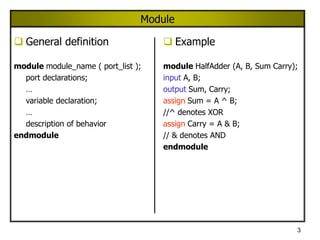
Dataflow Modeling
Uses continuous assignment statement
Format: assign [ delay ] net = expression;
Example: assign sum = a ^ b;
Delay: Time duration between assignment from RHS to
LHS
All continuous assignment statements execute
concurrently
Order of the statement does not impact the design](https://image.slidesharecdn.com/verilogtutorial1-230506113000-df1df756/85/verilog_tutorial1-pptx-10-320.jpg)


![25
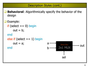
Data Types
Net Type: Wire
wire [ msb : lsb ] wire1, wire2, …
Example
wire Reset; // A 1-bit wire
wire [6:0] Clear; // A 7-bit wire
Register Type: Reg
reg [ msb : lsb ] reg1, reg2, …
Example
reg [ 3: 0 ] cla; // A 4-bit register
reg cla; // A 1-bit register](https://image.slidesharecdn.com/verilogtutorial1-230506113000-df1df756/85/verilog_tutorial1-pptx-25-320.jpg)

![27
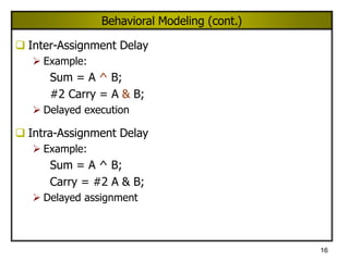
Memories
An array of registers
reg [ msb : lsb ] memory1 [ upper : lower ];
Example
reg [ 0 : 3 ] mem [ 0 : 63 ];
// An array of 64 4-bit registers
reg mem [ 0 : 4 ];
// An array of 5 1-bit registers](https://image.slidesharecdn.com/verilogtutorial1-230506113000-df1df756/85/verilog_tutorial1-pptx-27-320.jpg)
![28
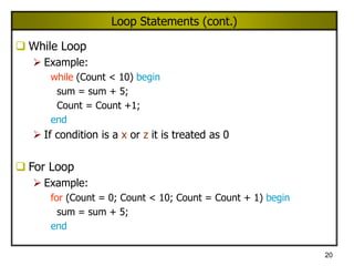
Compiler Directives
`define – (Similar to #define in C) used to define global
parameter
Example:
`define BUS_WIDTH 16
reg [ `BUS_WIDTH - 1 : 0 ] System_Bus;
`undef – Removes the previously defined directive
Example:
`define BUS_WIDTH 16
…
reg [ `BUS_WIDTH - 1 : 0 ] System_Bus;
…
`undef BUS_WIDTH](https://image.slidesharecdn.com/verilogtutorial1-230506113000-df1df756/85/verilog_tutorial1-pptx-28-320.jpg)


![34
Test Bench
`timescale 1ns/100ps
module Top;
reg PA, PB;
wire PSum, PCarry;
HalfAdder G1(PA, PB, PSum, PCarry);
initial begin: LABEL
reg [2:0] i;
for (i=0; i<4; i=i+1) begin
{PA, PB} = i;
#5 $display (“PA=%b PB=%b PSum=%b
PCarry=%b”, PA, PB, PSum, PCarry);
end // for
end // initial
endmodule
Test Bench
Design
Module
Apply Inputs
Observe Outputs](https://image.slidesharecdn.com/verilogtutorial1-230506113000-df1df756/85/verilog_tutorial1-pptx-34-320.jpg)


verilog_tutorial1.pptx
- 1. 1 Hardware Description Language (HDL) What is the need for Hardware Description Language? Model, Represent, And Simulate Digital Hardware Hardware Concurrency Parallel Activity Flow Semantics for Signal Value And Time Special Constructs And Semantics Edge Transitions Propagation Delays Timing Checks
- 2. 2 VERILOG HDL Basic Unit – A module Module Describes the functionality of the design States the input and output ports Example: A Computer Functionality: Perform user defined computations I/O Ports: Keyboard, Mouse, Monitor, Printer
- 3. 3 Module General definition module module_name ( port_list ); port declarations; … variable declaration; … description of behavior endmodule Example module HalfAdder (A, B, Sum Carry); input A, B; output Sum, Carry; assign Sum = A ^ B; //^ denotes XOR assign Carry = A & B; // & denotes AND endmodule
- 4. 4 Lexical Conventions Comments // Single line comment /* Another single line comment */ /* Begins multi-line (block) comment All text within is ignored Line below ends multi-line comment */ Number decimal, hex, octal, binary unsized decimal form size base form include underlines, +,- String " Enclose between quotes on a single line"
- 5. 5 Lexical Conventions (cont.) Identifier A ... Z a ... z 0 ... 9 Underscore Strings are limited to 1024 chars First char of identifier must not be a digit Keywords: See text. Operators: See text. Verilog is case sensitive
- 6. 6 Description Styles Structural: Logic is described in terms of Verilog gate primitives Example: not n1(sel_n, sel); and a1(sel_b, b, sel_b); and a2(sel_a, a, sel); or o1(out, sel_b, sel_a); sel b a out sel_n sel_b sel_a n1 a1 a2 o1
- 7. 7 Description Styles (cont.) Dataflow: Specify output signals in terms of input signals Example: assign out = (sel & a) | (~sel & b); sel b a out sel_n sel_b sel_a
- 8. 8 Description Styles (cont.) Behavioral: Algorithmically specify the behavior of the design Example: if (select == 0) begin out = b; end else if (select == 1) begin out = a; end a b sel out Black Box 2x1 MUX
- 9. 9 Structural Modeling Execution: Concurrent Format (Primitive Gates): and G2(Carry, A, B); First parameter (Carry) – Output Other Inputs (A, B) - Inputs
- 10. 10 Dataflow Modeling Uses continuous assignment statement Format: assign [ delay ] net = expression; Example: assign sum = a ^ b; Delay: Time duration between assignment from RHS to LHS All continuous assignment statements execute concurrently Order of the statement does not impact the design
- 11. 11 Dataflow Modeling (cont.) Delay can be introduced Example: assign #2 sum = a ^ b; “#2” indicates 2 time-units No delay specified : 0 (default) Associate time-unit with physical time `timescale time-unit/time-precision Example: `timescale 1ns/100 ps Timescale `timescale 1ns/100ps 1 Time unit = 1 ns Time precision is 100ps (0.1 ns) 10.512ns is interpreted as 10.5ns
- 12. 12 Dataflow Modeling (cont.) Example: `timescale 1ns/100ps module HalfAdder (A, B, Sum, Carry); input A, B; output Sum, Carry; assign #3 Sum = A ^ B; assign #6 Carry = A & B; endmodule
- 14. 14 Behavioral Modeling Example: module mux_2x1(a, b, sel, out); input a, b, sel; output out; always @(a or b or sel) begin if (sel == 1) out = a; else out = b; end endmodule Sensitivity List
- 15. 15 Behavioral Modeling (cont.) always statement : Sequential Block Sequential Block: All statements within the block are executed sequentially When is it executed? Occurrence of an event in the sensitivity list Event: Change in the logical value Statements with a Sequential Block: Procedural Assignments Delay in Procedural Assignments Inter-Statement Delay Intra-Statement Delay
- 16. 16 Behavioral Modeling (cont.) Inter-Assignment Delay Example: Sum = A ^ B; #2 Carry = A & B; Delayed execution Intra-Assignment Delay Example: Sum = A ^ B; Carry = #2 A & B; Delayed assignment
- 17. 17 Procedural Constructs Two Procedural Constructs initial Statement always Statement initial Statement : Executes only once always Statement : Executes in a loop Example: … initial begin Sum = 0; Carry = 0; end … … always @(A or B) begin Sum = A ^ B; Carry = A & B; end …
- 18. 18 Event Control Event Control Edge Triggered Event Control Level Triggered Event Control Edge Triggered Event Control @ (posedge CLK) //Positive Edge of CLK Curr_State = Next_state; Level Triggered Event Control @ (A or B) //change in values of A or B Out = A & B;
- 19. 19 Loop Statements Loop Statements Repeat While For Repeat Loop Example: repeat (Count) sum = sum + 5; If condition is a x or z it is treated as 0
- 20. 20 Loop Statements (cont.) While Loop Example: while (Count < 10) begin sum = sum + 5; Count = Count +1; end If condition is a x or z it is treated as 0 For Loop Example: for (Count = 0; Count < 10; Count = Count + 1) begin sum = sum + 5; end
- 21. 21 Conditional Statements if Statement Format: if (condition) procedural_statement else if (condition) procedural_statement else procedural_statement Example: if (Clk) Q = 0; else Q = D;
- 22. 22 Conditional Statements (cont.) Case Statement Example 1: case (X) 2’b00: Y = A + B; 2’b01: Y = A – B; 2’b10: Y = A / B; endcase Example 2: case (3’b101 << 2) 3’b100: A = B + C; 4’b0100: A = B – C; 5’b10100: A = B / C; //This statement is executed endcase
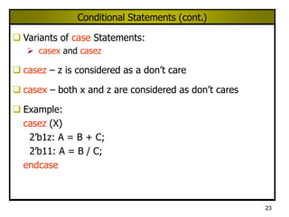
- 23. 23 Conditional Statements (cont.) Variants of case Statements: casex and casez casez – z is considered as a don’t care casex – both x and z are considered as don’t cares Example: casez (X) 2’b1z: A = B + C; 2’b11: A = B / C; endcase
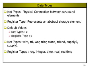
- 24. 24 Data Types Net Types: Physical Connection between structural elements Register Type: Represents an abstract storage element. Default Values Net Types : z Register Type : x Net Types: wire, tri, wor, trior, wand, triand, supply0, supply1 Register Types : reg, integer, time, real, realtime
- 25. 25 Data Types Net Type: Wire wire [ msb : lsb ] wire1, wire2, … Example wire Reset; // A 1-bit wire wire [6:0] Clear; // A 7-bit wire Register Type: Reg reg [ msb : lsb ] reg1, reg2, … Example reg [ 3: 0 ] cla; // A 4-bit register reg cla; // A 1-bit register
- 26. 26 Restrictions on Data Types Data Flow and Structural Modeling Can use only wire data type Cannot use reg data type Behavioral Modeling Can use only reg data type (within initial and always constructs) Cannot use wire data type
- 27. 27 Memories An array of registers reg [ msb : lsb ] memory1 [ upper : lower ]; Example reg [ 0 : 3 ] mem [ 0 : 63 ]; // An array of 64 4-bit registers reg mem [ 0 : 4 ]; // An array of 5 1-bit registers
- 28. 28 Compiler Directives `define – (Similar to #define in C) used to define global parameter Example: `define BUS_WIDTH 16 reg [ `BUS_WIDTH - 1 : 0 ] System_Bus; `undef – Removes the previously defined directive Example: `define BUS_WIDTH 16 … reg [ `BUS_WIDTH - 1 : 0 ] System_Bus; … `undef BUS_WIDTH
- 29. 29 Compiler Directives (cont.) `include – used to include another file Example `include “./fulladder.v”
- 30. 30 System Tasks Display tasks $display : Displays the entire list at the time when statement is encountered $monitor : Whenever there is a change in any argument, displays the entire list at end of time step Simulation Control Task $finish : makes the simulator to exit $stop : suspends the simulation Time $time: gives the simulation
- 31. 31 Type of Port Connections Connection by Position parent_mod
- 32. 32 Type of Port Connections (cont.) Connection by Name parent_mod
- 33. 33 Empty Port Connections If an input port of an instantiated module is empty, the port is set to a value of z (high impedance). module child_mod(In1, In2, Out1, Out2) module parent_mod(…….) input In1; input In2; child_mod mod(A, ,Y1, Y2); output Out1; //Empty Input output Out2; endmodule //behavior relating In1 and In2 to Out1 endmodule If an output port of an instantiated module is left empty, the port is considered to be unused. module parent_mod(…….) child_mod mod(A, B, Y1, ); //Empty Output endmodule
- 34. 34 Test Bench `timescale 1ns/100ps module Top; reg PA, PB; wire PSum, PCarry; HalfAdder G1(PA, PB, PSum, PCarry); initial begin: LABEL reg [2:0] i; for (i=0; i<4; i=i+1) begin {PA, PB} = i; #5 $display (“PA=%b PB=%b PSum=%b PCarry=%b”, PA, PB, PSum, PCarry); end // for end // initial endmodule Test Bench Design Module Apply Inputs Observe Outputs
- 35. 35 Test Bench - Generating Stimulus Example: A sequence of values initial begin Clock = 0; #50 Clock = 1; #30 Clock = 0; #20 Clock = 1; end
- 36. 36 Test Bench - Generating Clock Repetitive Signals (clock) Clock A Simple Solution: wire Clock; assign #10 Clock = ~ Clock Caution: Initial value of Clock (wire data type) = z ~z = x and ~x = x
- 37. 37 Test Bench - Generating Clock (cont.) Initialize the Clock signal initial begin Clock = 0; end Caution: Clock is of data type wire, cannot be used in an initial statement Solution: reg Clock; … initial begin Clock = 0; end … always begin #10 Clock = ~ Clock; end forever loop can also be used to generate clock