


Anesthesia machine
- 1. Anesthesia machine Presented to Dr D.M MAKHDOOI PROFESSOR AND HEAD DIVISION OF VSR SKUAST K
- 3. Introduction The anesthesia machine is a device that delivers precisely known but variable gas mixtures under controlled conditions. The Anesthesia machine contains mechanical respiratory support (ventilator) and O2 support as well as being a means for administering anesthetic gases which may be used for sedation as well as total anesthesia.
- 4. HISTORY The concept of anesthetic machine was given by Henry boyle in 1917. In 1920 vapourizing bottle was inco porated. In 1926 bypass controls were introduced. In 1933 flowmeter device was incorporated HENRY BOYLE
- 5. TYPES OF ANESTHETIC MACHINE INTERMITTENT gas flows only during inspiration e.g entonex apparatus CONTINIOUS gas flows both during inspiration and expiration e.g boyls machine
- 6. Three pressure systems High pressure system •From cylinder to pressure reducing valves Intermediate pressure system •From pressure reducing valves to flowmeter. Low pressure system •From flowmeters to common gas outlet.
- 7. Components of anesthetic machine
- 9. COMPRESSED GAS CYLINDER:- •Pressurized container used for storage and transport carrier gas and oxygen. •They are made up of chrome molybdenum and aluminium. Non liquified gas These are gases that do not liquify at ambient temperature regardless of pressure applied e.g O2,N2. Liquified compressed gas gas becomes liquid when compressed by a pressure of 25- 100 psi
- 10. International colour coding of anesthetic cylinders.
- 11. TANK PRESSURE GUAGE •INDICATES THE PRESSURE OF GAS REMAINING IN A COMPRESSED GAS CYLINDER. •MEASURED IN POUNDS PER SQU ARE INCH. •DETERMINE NO OF LITRES of gas REMaINING IN A TANK.
- 12. PRESSURE REDUCING VALVES As oxygen moves from the high-pressure tank (at up to 2200 psi) into the anesthetic machine, the pressure is lowered by a regulator to provide a safe operating pressure (45-50 psi). Regulator also provides for constant flow as the pressure in the tank decreases. Regulators used at HSVMA-RAVS clinics mount on top of the oxygen tanks.
- 13. FLOWMETER From the cylinder, pressure gauge and pressure-reducing valve, oxygen travels through a low-pressure hose to the flowmeter. Allows anesthetist to provide measured amount of oxygen to the patient Flow rates are expressed in liters of gas per minute (L/min). Oxygen enters the flowmeter and is delivered to the vaporizer at a constant rate as indicated on the flowmeter dial.
- 14. OXYGEN FLOW RATES Recommended oxygen flow rates for patients on a non-rebreathing system are at least 200- 300 ml/kg/min, with the minimum flow rate being 1 L/min. Patients on a semi-closed (circle) system are run at a flow rate of 20-50 ml/kg/min with a maximum of 2 L/min. In general, an oxygen flow rate of 1-2 L/min is appropriate for most patients. With some vaporizers flow rates less than 1000 ml/minute will not allow accurate delivery of the dialed vaporizer concentration.
- 15. VAPORIZER Oxygen exits the top of the flowmeter and continues via a low-pressure hose to the vaporizer. The vaporizer is designed to convert liquid anesthetic to vapor and to add a controlled amount of vapor to the carrier gas flowing through the machine. If the oxygen flow is turned off, no anesthetic is delivered to the patient. A tube running from the “outlet” side of the vaporizer attaches to the breathing circuit and is called the “common gas outlet”. An indicator window at the base of the vaporizer indicates the amount of liquid anesthetic remaining..
- 16. vapourizer
- 17. COMMON GAS OUTLET The common gas outlet is where the oxygen/medical gas/anesthetic agent mixture exits the anesthesia machine to the breathing system, which can be either a rebreathing or nonrebreathing system.
- 18. OXYGEN FLUSH VALUE The oxygen flush valve is used to bypass the vaporizer and delivers oxygen only to the common gas outlet then to the breathing circuit. The O2 flush valve delivers a high flow of about 30 or more liters per minute depending on the machine. Note Do not use the oxygen flush valve to fill the breathing circuit with oxygen while connected to a patient. This may cause damage to patient’s lungs due to the sudden increase in volume pressure. Turn up the flow on the flowmeter to fill the system when a patient is connected to the breathing circuit.
- 19. BREATHING SYSTEM
- 20. Properties of the ideal breathing system Simple and safe to use Delivers the intended inspired gas mixture Permits spontaneous, manual and controlled ventilation in all size groups Efficient, requiring low fresh gas flow rate Protects the patient from barotraumas Sturdy, compact and lightweight in design Permits easy removal of waste exhaled gases Easy to maintain with minimal running cost
- 21. TYPES REBREATHING • To n fro system. • Circle system NON REBREATHING SYSTEM • Magill system • Brain circuit • Lack system • Coaxial system
- 23. REBREATHING SYSTEM The rebreathing or circle system allows for the rebreathing of the exhaled gases. The CO2 is removed and the fresh gas mixture is continually added. Usually used for patients that weigh greater than 7kgs(15lbs). The components of a rebreathing system are fresh gas inlet, absorber circuit, manometer, rebreathing bag, hoses, Y piece, unidirectional valves (inspiration & expiration), pop off valve, and a scavenger system.
- 24. Circle system
- 26. REBREATHING SYSTEM The components of the rebreathing system increase the resistance to the movement of the gas mixture in the system comparatively to a non-rebreathing. Thus smaller patients may have more difficulty inhaling the gas mixture. The rebreathing systems are more economical because the gas flows are less. Changes in anesthetic depth are relatively slow due to the lower flow rate of the gas mixture.
- 27. FRESH GAS INLET Fresh gas inlet is where the gas mixture enters the breathing system. The inlet is usually located on the inspiratory side of a rebreathing circle system. This minimizes the dilution of the fresh gas with the expired gases, absorption of dust and the loss of fresh gas through the popoff valve.
- 28. UNIDIRECTIONAL VALVES Unidirectional Valves prevent expired gases from being recirculated and Breathing tubes and Y-piece connect the patient to the absorber circuit. The Y-piece is connected to the endotracheal tube and the other ends of the hoses are connected at the expiratory and inspiratory valves. Upon inspiration, the inspiratory valve will open and allow the gas mixture to flow toward the patient. At expiration, the inspiratory valve will close and the expiratory valve will open to allow the expired gases to pass into the absorber circuit
- 29. REBREATHING BAG Rebreathing Bag provides a tidal volume for the patient and compliance for the system. The rebreathing bag is used to store gases, observation of respirations, and to manually ventilate a patient.
- 30. ABSORBER CANISTER Absorber canister is where CO2 is removed from the expired gases. As the absorber is used the granules will change to a blue color as it becomes exhausted. The granules will return back to a normal color when not in use after sometime has passed. Fresh granules will be soft and easily crushed while exhausted granules will be hard and brittle.
- 31. reaction • CO2 + H2O → H2CO3 • H2CO3 + 2 NaOH → Na2CO3 + 2H2O • H2CO3 + 2KOH → K2CO3 + 2H2O • Na2CO3 (or K2CO3) + Ca(OH)2 → 2NaOH (or 2KOH) + CaCO3. • Soft and crushable granules are converted to hard and non-crushable granules (calcium hydroxide changes to calcium carbonate - limestone) which indicates exhausted sodalime.
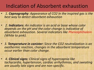
- 32. Indication of Absorbent exhaustion • 1. Capnography: Appearance of CO2 in the inspired gas is the best way to detect absorbent exhaustion • 2. Indicators: An indicator is an acid or base whose color depends on the pH and the color change is indicative of absorbent exhaustion. Several indicators like Phenolphthalein (White to pink). • 3. Temperature in canister: Since the CO2 neutralization is an exothermic reaction, changes in the absorbent temperature occur earlier than color change. • 4. Clinical signs: Clinical signs of hypercapnia like tachycardia, hypertension, cardiac arrhythmias, and sweating are usually late signs and are non-specific.
- 33. POP OFF VALVE Pop off valve or APL valve is used to allow the excess/waste gases to be vented to a scavenging system and allows the anesthetist to increase the pressure in the breathing system when needed. The pop off valve is usually left open when the patient is spontaneously breathing and closed for manual or mechanical ventilation. The valve can be adjusted as needed to accommodate the appropriate pressure needed for that particular patient.
- 34. FILTERS • Bacterial filters: These are meant to prevent transmission of infection to the patient or contamination of the equipment. The recommendations for their use vary for different countries. Generally a new filter should be used for every patient or in the absence of a filter a disposable system should be used for every patient. Filters are generally not preferred for paediatric patients.
- 35. . Heat and Moisture Exchange (HME) filters: Administration of dry gases at room temperature could lead to heat loss and increased pulmonary complication. The function of the nose is to warm and humidify inhaled gases. When the nose is bypassed it is advisable to use HME filters to achieve this objective. These devices also help to dehumidify the gases that are being sampled for analysis by side stream devices
- 36. Circle system
- 37. To n fro system
- 38. ADVANTAGES Economical Expired oxygen and anesthetic vapor are recirculated and reused . Fresh gas flow and anesthetic agent utilization are minimized . Humidifying inspired gas Preserving heat and moisture of the patient.
- 39. NON REBREATHING BAG A non-rebreathing system has less drag on the ET tube than does a rebreathing system. Due to the higher flow rates needed for a non- rebreathing the cost does increase as compared to a rebreathing system. The components of a non-rebreathing system differ from a rebreathing system as that there are no unidirectional valves, manometer, or absorber circuit. The use of a reservoir bag allows for bagging when needed and a buffer between the scavenging system.
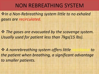
- 40. NON REBREATHING SYSTEM In a Non-Rebreathing system little to no exhaled gases are recirculated. The gases are evacuated by the scavenge system. Usually used for patient less than 7kgs(15 lbs). A nonrebreathing system offers little resistance to the patient when breathing, a significant advantage to smaller patients.
- 41. magil system
- 42. T piece system
- 43. Lack circuit
- 44. Brain system
- 45. • Recommended for ; - • Small dogs & cats • Neonates • Small birds • Pocket pets • Small exotic animals
- 46. Scavenging System The scavenging system removes the waste anesthetic gases from the anesthetic breathing system and reduces the contamination of the workplace. There are two types of scavenging systems. The passive system uses the positive pressure of the anesthetic machine to push the gas into the system. The other is an active system, which uses suction created by a vacuum pump or fan to draw the gas into the system
- 47. SCAVANGING SYSTEM Both systems are effective when correctly assembled, operated, and maintained properly. However, the active system appears to be the most efficient in removing waste gases.