


![27
Swap Instructions
Allow a value in a register to be exchanged with a value in memory.
Effectively do both a load and a store operation in one instruction.
They are little used in user-level programs.
Syntax: SWP{B} Rd, Rm, [Rn]
SWP Word exchange tmp = mem32[Rn]
mem32[Rn] = Rm
Rd = tmp
SWPB Byte exchange tmp = mem16[Rn]
mem16[Rn] = Rm
Rd = tmp](https://image.slidesharecdn.com/armprogramming-250707070533-52adc5d3/85/ARM-Programming-pptxARM-instructions-process-data-held-in-registers-and-only-access-memory-with-load-and-store-instructions-27-320.jpg)
ARM Programming.pptxARM instructions process data held in registers and only access memory with load and store instructions.
- 1. 1 ARM PROGRAMMING PREPARED BY DEBASISH MOHANTA ASSISTANT PROFESSOR DEPARTMENT OF ELECTRICAL ENGINEERING GOVERNMENT COLLEGE OF ENGINEERING, KEONJHAR
- 2. 2 ARM Programming ARM instructions process data held in registers and only access memory with load and store instructions. ARM instructions commonly take two or three operands. For instance the ADD instruction below adds the two values stored in registers r1 and r2 (the source registers). It writes the result to register r3 (the destination register). Instruction syntax Destination register (Rd) Source register 1 (Rn) Source register 2 (Rm) ADD r3,r1,r2 r3 r1 r2
- 3. 3 Data Processing Instructions The data processing instructions manipulate data within registers. move instructions, arithmetic instructions, logical instructions, comparison instructions, and multiply instructions. Most data processing instructions can process one of their operands using the barrel shifter. If you use the S suffix on a data processing instruction, then it updates the flags in the cpsr. Move and logical operations update the carry flag C, negative flag N, and zero flag Z. The carry flag is set from the result of the barrel shift as the last bit shifted out. The N flag is set to bit 31 of the result. The Z flag is set if the result is zero.
- 4. 4 Move Instructions Move is the simplest ARM instruction. It copies N into a destination register Rd, where N is a register or immediate value. This instruction is useful for setting initial values and transferring data between registers. Syntax: <instruction>{<condition>}{S} Rd, N Example: PRE r5 = 5 r7 = 8 MOV r7, r5 ; let r7 = r5 POST r5 = 5 r7 = 5 MOV Move a 32-bit value into a register Rd = N MVN move the NOT of the 32-bit value into a register Rd = ~ N
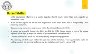
- 5. 5 Barrel Shifter MOV instruction where N is a simple register. But N can be more than just a register or immediate value; N can also be a register Rm that has been preprocessed by the barrel shifter prior to being used by a data processing instruction. Data processing instructions are processed within the arithmetic logic unit (ALU). A unique and powerful feature: the ability to shift the 32-bit binary pattern in one of the source registers left or right by a specific number of positions before it enters the ALU. This shift increases the power and flexibility of many data processing operations. Pre-processing or shift occurs within the cycle time of the instruction. This is particularly useful for loading constants into a register and achieving fast multiplies or division by a power of 2.
- 6. 6 Barrel Shifter Pre-processing or shift occurs within the cycle time of the instruction. This is particularly useful for loading constants into a register and achieving fast multiplies or division by a power of 2. PRE r5 = 5 r7 = 8 MOV r7, r5, LSL #2 ; let r7 = r5*4 = (r5<<2) POST r5 = 5 r7 = 20
- 7. 7 Barrel Shifter Five different shift operations that you can use within the barrel shifter are:
- 8. 8 Barrel Shifter MOVS instruction shifts register r1 left by one bit. This multiplies register r1 by a value 21.
- 10. 10 Arithmetic Instructions The arithmetic instructions implement addition and subtraction of 32-bit signed and unsigned values.
- 11. 11 Barrel Shifter with Arithmetic Instructions The wide range of second operand shifts available on arithmetic and logical instructions is a very powerful feature of the ARM instruction set. Register r1 is first shifted one location to the left to give the value of twice r1. The ADD instruction then adds the result of the barrel shift operation to register r1.
- 12. 12 Logical Instructions Logical instructions perform bitwise logical operations on the two source registers.
- 13. 13 Logical Instructions This example shows a more complicated logical instruction called BIC, which carried out a logical bit clear. Register r2 contains a binary pattern where every binary 1 in r2 clears a corresponding bit location in register r1. This instruction is particularly useful when clearing status bits and is frequently used to change interrupt masks in the cpsr. The logical instructions update the cpsr flags only if the S suffix is present. These instructions can use barrel-shifted second operands in the same way as the arithmetic instructions.
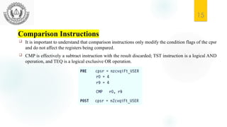
- 14. 14 Comparison Instructions The comparison instructions are used to compare or test a register with a 32-bit value. They update the cpsr flag bits according to the result, but do not affect other registers. After the bits have been set, the information can then be used to change program flow by using conditional execution.
- 15. 15 Comparison Instructions It is important to understand that comparison instructions only modify the condition flags of the cpsr and do not affect the registers being compared. CMP is effectively a subtract instruction with the result discarded; TST instruction is a logical AND operation, and TEQ is a logical exclusive OR operation.
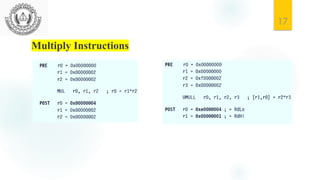
- 16. 16 Multiply Instructions The multiply instructions multiply the contents of a pair of registers and, depending upon the instruction, accumulate the results in with another register. The long multiplies accumulate onto a pair of registers representing a 64-bit value. The final result is placed in a destination register or a pair of registers.
- 18. 18 Branch Instructions A branch instruction changes the flow of execution or is used to call a routine. This type of instruction allows programs to have subroutines, if-then-else structures, and loops. The change of execution flow forces the program counter pc to point to a new address. The branch exchange (BX) and branch exchange with link (BLX) are the third type of branch instruction. The BX instruction uses an absolute address stored in register Rm. It is primarily used to branch to and from Thumb code.
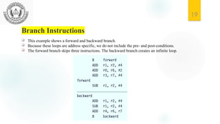
- 19. 19 Branch Instructions This example shows a forward and backward branch. Because these loops are address specific, we do not include the pre- and post-conditions. The forward branch skips three instructions. The backward branch creates an infinite loop.
- 20. 20 Load-Store Instructions Load-store instructions transfer data between memory and processor registers. There are three types of load store instructions: single-register transfer, multiple-register transfer, and swap. Single-Register Transfer: These instructions are used for moving a single data item in and out of a register. The data types supported are signed and unsigned words (32-bit), half words (16-bit), and bytes. Here are the various load-store single-register transfer instructions.
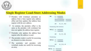
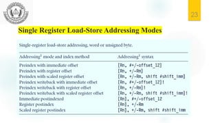
- 21. 21 Single Register Load-Store Addressing Modes The ARM instruction set provides different modes for addressing memory. These modes incorporate one of the indexing methods: preindex with writeback, preindex, and postindex. Preindex with writeback calculates an address from a base register plus address offset and then updates that address base register with the new address. In contrast, the preindex offset is the same as the preindex with writeback but does not update the address base register. Postindex only updates the address base register after the address is used. The preindex mode is useful for accessing an element in a data structure. The postindex and preindex with writeback modes are useful for traversing an array.
- 22. 22 Single Register Load-Store Addressing Modes Preindex with writeback calculates an address from a base register plus address offset and then updates that address base register with the new address. In contrast, the preindex offset is the same as the preindex with writeback but does not update the address base register. Postindex only updates the address base register after the address is used. The preindex mode is useful for accessing an element in a data structure. The postindex and preindex with writeback modes are useful for traversing an array.
- 23. 23 Single Register Load-Store Addressing Modes
- 24. 24 Multiple Register Transfer Load-store multiple instructions can transfer multiple registers between memory and the processor in a single instruction. The transfer occurs from a base address register Rn pointing into memory. Multiple-register transfer instructions are more efficient from single-register transfers for moving blocks of data around memory and saving and restoring context and stacks. If an interrupt has been raised, then it has no effect until the load-store multiple instruction is complete.
- 25. 25 Multiple Register Transfer In this example, register r0 is the base register Rn and is followed by !, indicating that the register is updated after the instruction is executed. You will notice within the load multiple instruction that the registers are not individually listed. Instead the “-” character is used to identify a range of registers. In this case the range is from register r1 to r3 inclusive. • Each register can also be listed, using a comma to separate each register within “{” and “}” brackets.
- 27. 27 Swap Instructions Allow a value in a register to be exchanged with a value in memory. Effectively do both a load and a store operation in one instruction. They are little used in user-level programs. Syntax: SWP{B} Rd, Rm, [Rn] SWP Word exchange tmp = mem32[Rn] mem32[Rn] = Rm Rd = tmp SWPB Byte exchange tmp = mem16[Rn] mem16[Rn] = Rm Rd = tmp