THERMODYNAMICS
Dinesh Panchal
BASICS OF THERMODYNAMICS
WORKING SUBSTANCE:
The working substance is mostly gas or vapors and liquid in
equilibrium. It is very important to know the behavior of the substance and its
properties
Pure substances are those which have homogeneous chemical
structure. Water is the example of pure substance. Air is also considered as a pure
substance in gaseous form.
Thermodynamics System:
It is defined as the space on which attention is concentrated to analyze it.
Thermodynamics Surrounding :
It is defined as the remaining space of the universe except system
Dinesh Panchal
Boundary:
An envelop enclosing the system is known as boundary.
Universe:
When the system and surrounding are put together, is called universe.
Types of Systems:
1. Open System
2. Closed System
3. Isolated System
1. Open system: A system is called open when there is transfer of mass as well
as heat between the system and surrounding.
2. closed system: A system is called closed when there is transfer of heat
between the system and surrounding and there is no transfer of mass
between system and surrounding.
3. Isolated system: A system is called isolated when there is transfer no
transfer of mass as well as heat between the system and surrounding
Dinesh Panchal
Property or Parameters of substance:
Property or Parameters are those quantities which specify the state of the
substance. So we can say that the properties of a substance dependent on the state
of substance e.g. Mass, Physical Composition, Vol., Pressure, Temp, Surface Area,
Velocity, Thermal Conductivity, Entropy, Enthalpy ect.
Types of Properties :
1. Intensive Properties
2. Extensive Properties
1. Intensive Properties: Are those properties which does not depend on the
mass of system. E.g. pressure, temp., density, velocity , height, viscosity
2. Extensive Properties: Are those properties which depend on the mass of
system. E.g. vol., Surface area, internal energy, potential energy
Dinesh Panchal
Pressure:
Pressure is defined as the force per unit area. Its unit is Pascal, Bar,
N/M2.
Atm. Pressure :
It is the pressure exerted by the weight of air column on the surface
of earth is called atm. Pressure.
Atm. Pressure = hρg Where h is the height of air column, ρ is
the density of air, g is acc. due to gravity
Gauge. Pressure :
Pressure measured by the pressure gauge is called gauge pressure
and it is one atm. less pressure than the absolute pressure. It is the
pressure above the atm. Pressure.
Absolute Pressure :
Absolute pressure is the total pressure.
Absolute Pressure= Atm. Pressure+ Gauge Pressure
gaugeatmabs PPP  ..
Dinesh Panchal
262
36-
2
2
25
/10/1
10101Torr1
980665.0/1
lbf/in14.696Hg.of760mmPa101325Atm.1
/10Bar1
mNmmN
mmHgmHg
Barcmkgf
mN







Dinesh Panchal
Thermodynamic Equilibrium:
A system is said to be in thermal equilibrium if the value of property is same
at all the points of the system. For thermodynamic equilibrium following
condition must be satisfied.
1. Mechanical Equilibrium
2. Chemical Equilibrium
3. Thermal Equilibrium
1. Mechanical Equilibrium:
A system is said to be in mechanical equilibrium if Algebraic sum of
all the forces and moments are zero
2. Chemical Equilibrium:
A system is said to be in chemical equilibrium if there is no chemical
reaction with in the system.
3. Thermal Equilibrium:
A system is said to be in thermal equilibrium if there is no temp.
difference between the parts of system.
Dinesh Panchal
State:
Instantaneous condition on of a thermodynamic system is called state. It the
condition of the system at any time. The state of the system is define by the
temp. pressure vol. density.
Path :
It is the locus of points of states at different time.
Process:
A process is defined as when a system changes its state from one state to
another state.
Dinesh Panchal
Cyclic Process :
When a process or processes are performed on the system in such
away that the final state is same with the initial state.
Reversible Process:
If the process in the reverse, follow the same path from one state to
another state as the path traced during forward path called reversible path.
Irreversible Process:
If the process in the reverse, do not follow the same path from one
state to another state as the path traced during forward path called irreversible
path. Dinesh Panchal
Energy :
It is the capacity to do work.
1. Mechanical Energy
(a) Potential Energy: It is the energy possessed by virtue of its
position .e.g. Potential energy due to height
P.E. =mgh
(b) Kinetic Energy : It is the energy possessed by virtue of its
motion .
K.E. =1/2mv2
2. Internal Energy:
It is the energy possessed by the body due to its molecular
arrangement and motion of the molecules.
3. Total Energy:
It is the sum of K.E., P.E. and I.E.
E=P.E.+K.E.+U
Dinesh Panchal
Law of conservation of Energy :
It state that energy can neither be created nor be destroyed, but can be
changed from one form to another form. It means electrical energy can be
converted in to mech. Energy and vice versa. Similarly thermal energy can be
converted in to mechanical or electrical energy.
Law of conservation of Mass:
It state that mass can neither be created nor be destroyed, but can be
changed from one form to another form. A solid can be changed from solid
to liquid, liquid to gas or vice versa.
Heat:
Heat is defined as the energy that is transferred across the boundary of a
system due to temp. difference. Heat flow from high temp. to low temp.
 
gsurroundinandsystembetweendifferencetemptheisT-T
heatspecifictheisc
systemofmasstheismWhere
T-TcmferredHeat trans
21
21
Dinesh Panchal
Specific Heat :
Specific Heat is defined as the amount of heat required to raise the temp.
of the unit mass through one degree centigrade.
It has two type
(a) Specific heat at constant volume :
It is defined as the amount of heat
required to raise the temp. of the
unit mass through one degree
centigrade at constant volume. It is
denoted by
(b) Specific heat at constant pressure:
It is defined as the amount of heat
required to raise the temp. of the
unit mass through one degree
centigrade at constant Pressure.
It is denoted by
vC
pC
Dinesh Panchal
Sign Convention for Heat and Work :
# Work done by the System is +ve
# Work done on the System is -ve
# Heat Transferred to the system is +ve
# Heat Transferred from the system is –ve
Gas Law :
It is the relation between Temperature, Volume, Pressure and mass of a gas
at any particular state.
KKgJ/872R
KKJ/mol8.314R
eTemperaturtheisT
molesofno.theis-n
masstheism
VolumetheisV
PressuretheisP








nRTPV
mRTPV
Dinesh Panchal
Boyle’s Law : (Isothermal Process)
The absolute pressure of a given mass of perfect gas varies inversely
proportional to its volume at constant temp.
2211So.
Constant
1
VPVP
PV
V
P


Dinesh Panchal
Boyle’s Law : (Isobaric Process)
The absolute volume of a given mass of perfect gas varies directly
proportional to its volume.
2
2
2
1
So.
Constant
T
V
T
V
T
V
TV


Dinesh Panchal
Gay – Lussac Law : (Isochoric Process)
It state that the absolute pressure of a given mass of a perfect gas
varies directly as its temperature.
2
2
1
1
So.
Constant
T
T
P
T
P
P
TP


Dinesh Panchal
Temperature :
Temp. is defined as the hotness and coldness of the system or body. Its unit of
measurement are Celsius or Centigrade, Fahrenheit and Kelvin. Relation
between these temp. measuring scale is given below .
Absolute Zero Temp. :
It is defined as the temp below which temp. does not fall. Its value is
Zeroth Law of Temperature :
It state that if body A is in thermal equilibrium
with body B and body B is in thermal
equilibrium with body C then body A is also
thermal equilibrium with body C.
180
32
100


FC
KC 00
0273 
Dinesh Panchal
First Law of Thermodynamics :
It state that heat and mechanical work are mutually convertible. In others
words cyclic integral of heat transfer equal to the cyclic integral of work.
Another statement is that Energy can neither be created nor be destroyed,
but can be changed from one form to another.
  WQ 
2
2
2
22
1
2
1
11
2
1
21
21
122121
2
1
1
1
2
1
2
2
2stateatsystemofenergyTotal-
1stateatsystemofenergyTotal-
procsstheduringgsurroundinon thesystemby thedoneWork-
2stateto1statefromsystemtheoTransfer tHeat-
U
mV
mgzE
U
mV
mgzE
E
E
W
Q
EEWQ
dEWQ
dEWQ








  

Dinesh Panchal
Application of first law to non flow processes:
1. Constant Volume Process:
If the volume remains constant during the process , then the process is
called Isochoric or constant volume process.
 
 
WdU
iii
TTmCU
iii
VVP
ii
T
P
T
VP
i
v
 




Q
TransferHeat)(
U
EnergyInternalinChange)(
W
Gasby thekdoneWor)(
T
P
VVBut
T
VP
VolumeandeTemperatur,PressurebetweenRelation)(
1221
122-1
2
2
1
1
21
2
22
1
11
Dinesh Panchal
2. Constant Temperature (Isothermal Process) :
In this process temperature remains constant throughout the
process. This process is called Isothermal Process.
 
0AsQ
Q
TransferHeat)(
0USo
ButU
EnergyInternalinChange)(
log3.2
log3.2logW
Gasby thekdoneWor)(
VPVP
TTBut
T
VP
VolumeandeTemperatur,PressurebetweenRelation)(
21
121221
1
2
101
1
2
1011
1
2
112-1
2211
21
2
22
1
11








dUW
WdU
iv
U
TTTTmCU
iii
V
V
mRT
V
V
VP
V
V
VP
ii
T
VP
i
v
e


Dinesh Panchal
 
 
 
Q
TransferHeat)(
U
EnergyInternalinChange)(
W
Gasby thekdoneWor)(
Constant
T
V
T
V
PPBut
T
VP
VolumeandeTemperatur,PressurebetweenRelation)(
12
1221
122-1
2
2
1
1
21
2
22
1
11
TTmC
WdU
iv
TTmCU
iii
TTmR
ii
T
VP
i
p
v







2. Constant Pressure (Isobaric Process) :
In this process pressure remains constant throughout the process.
This process is called Isobaric Process.
Dinesh Panchal
3. Adiabatic Process (Isentropic Process) :
In this process there is no heat addition or removal from the syatem
to surrounding.
 
 
0Q
TransferHeat)(
U
EnergyInternalinChange)(
1
1
W
Gasby thekdoneWor)(
PVPV
VTVT
VPVP
VolumeandeTemperatur,PressurebetweenRelation)(
1221
21
2211
2-1
1
22
1
11
1-
22
1-
11
2121


















iv
TTmCU
iii
TTmR
VPVP
ii
i
v
Dinesh Panchal
QUESTION NO. 1 (A) A dry saturated steam at a pressure of 600KPa is contained in a
thermally insulated cylinder fitted with a frictional piston. As the piston moves outwards, the
steam expands to a pressure 60KPa.Calculatye the work done by the gas.
Dinesh Panchal
 
   
KJJ
Rm
Rm
K
BarKPa
KC
BarKPa
383.1495.149383
4.0
4.59753
6.2328.314
14.1
1287
TT
1
W
J/KgK287RofValueand1KgM:massunitfordoneWork
TT
1
WexpansionadiabaticforWorkdone
6.223
6
0.6
8.314T
P
P
TT
P
P
T
T
processadiabaticFor
?T
6.060P
:ConditionsfinalThe
Table)SteamFrom(8.4312738.1588.158Tpressureat this
TempSaturatedSosaturated.dryissteamtheAnd
6600P
:ConditionsInitial
21
21
0
4.1
14.1
2
1
1
2
12
1
1
2
1
2
1
2
00
1
1











































Free Expansion :
The free expansion process is an irreversible process. Free expansion
is a process in which the fluid expands suddenly in to the vacuum
chamber.
In this process no external heat is supplied and no external work
is done. In this process enthalpy of the system remains constant.
Limitations of 1st Law of Thermodynamics:
0
0W0 2-121


dU
Q
Dinesh Panchal
Heat Engine :
Heat engine is a device which convert heat energy in to mechanical
work in cyclic process. In heat engine high pressure and temp steam is generated in
the boiler and supplied to the steam turbine. Turbine convert the heat energy of
steam in to mechanical work.
Suppose a heat engine is working between two heat reservoir one at high temp
and one at low temp. Heat is supplied by the reservoir at high temp. and heat is
rejected to the reservoir at low temp.
h
l
h
l
1
lh
lh
l
h
T
T
1
Q
Q
1
Q
QQ
SuppliedHeat
Workdone
EfficiencyThermal
QQ
engineby theRejectedHeat-
enginethetoSuppliedHeatEngineby theWorkdone
Qengineby theRejectedHeat
QenginethetoSuppliedHeat









Dinesh Panchal
Heat Pump :
Heat engine is a device which transfer heat energy from low temp to
high temp. this can be done by doing the external work on the system.
Suppose a heat pump is working between two heat reservoir one at high temp and
one at low temp. Heat is transferred from low temp to high temp.
LH
H
LH
H
LH
H
L
TT
T
QQ
Q
neNet Workdo
EffectDesired
EfficiencyThermal
QQ
SuppliedHeat-
RejectedHeat
PumpHeatby theRequiredWorkdone
QPumpHeatby theRejectedHeat
QPumpHeatthetoSuppliedHeat










NETW
Dinesh Panchal
Second Law of Thermodynamics:
1. Kelvin – Planks Statement : It is impossible to construct a heat engine
which operate in a cycle, will produce no effect other than the exchange of
heat from a single reservoir and produce work . Or no actual engine operating
in a cycle can convert whole of heat energy supplied to it in to work.
2. Clausius Statement : It is impossible to construct a heat pump, which is
operating in a cycle, will produce no effect other than the transfer of heat
from lower temp. body to higher temp. body. Or heat can not flow from
lower temp. to higher temp. without help of external work
Third Law of Thermodynamics:
This law state that absolute value of entropy can not be achieved. The
entropy of perfect crystal is zero at absolute zero temp.
Dinesh Panchal
Enthalpy:
Enthalpy is the sum of internal energy and the product of pressure and
volume or work done
Enthalpy = U + p V
Where U is the internal energy
P is the pressure
V is the volume
Internal Energy:
Internal energy is defined as the sum of all the microscopic forms of energy of
the system. It is the energy associated with the molecular activity of the
constituent partials of the system. It is the sum of kinetic energy and potential
energy of the partials. It is denoted by U.
Entropy :
It is the function of quantity of heat which shows the possibility of conversion
of that heat in to useful work. It is an important thermodynamic property of a
working substance, which increases with the addition of heat and decreases with
its removal.
Temp.absolutetheisT
substanceby theabsoredheattheisWhere Q
TdSQ

 
Dinesh Panchal
THERMODYNAMICS PROPERTIES OF STEAM
1. Vaporization: It is the process of change of liquid to vapor phase. Water vapor
are obtained by vaporization and steam from boiling.
2. Evaporation: is the process of vapor generation only from the surface of the
liquid.
3. Boiling :- is the process of vapor formation that take place in the whole mass
of the liquid.
4. Saturated Temperature:- The boiling of liquid take place at a definite temp.
and this temp dependent on the pressure called saturate temp. It is denoted
by
5. Saturated Pressure:- The boiling of liquid take place at a definite Pressure at
given temp. called Saturate Pressure . It is denoted by .
st
sp
Dinesh Panchal
THERMODYNAMICS PROPERTIES OF STEAM
1. WET STEAM:- When the steam contain moist or water partial called wet steam.
2. DRY SATURATED STEAM:- When the wet steam is further heated and it does not
contain any suspended partials of water it is known as dry saturated steam.
Dry saturated steam absorbed its full latent heat.
3. SUPERHEATED STEAM:- When the dry stem is further heated at constant
pressure for raising its temp then it is to be said superheated steam.
4. DRYNESS FRACTION:- It is the ratio of mass of actual dry steam to mass of total
mass of wet steam denoted by x
5. Latent Heat of Vaporization:- It is the amount of heat absorbed to evaporate 1
kg of water at its boiling point or saturation temp without change in temp.
fg
g
mm
m
x


kgkjhfg /2257
Dinesh Panchal
1. Sensible heat of Water:- :- It is the amount of heat absorbed by 1 kg of water, when
heated at a constant pressure from to the temp of formation of steam
2. Latent Heat of vaporization: It is the quantity of heat required to convert 1 kg. of water
at saturation temp. at a given pressure in to dry saturated steam at
that temp. and pressure. It is denoted by
3. Enthalpy or Total Heat of steam:- It is the amount of heat absorbed by the water from
freezing point to saturation temp plus heat absorbed during
evaporation Enthalpy= Sensible Heat + Latent Heat•
(1) Wet Steam
(2) Dry Steam
(3) Superheated steam
KgtKJhf /2.4
fgf xhhh 
)*1( fgfg hhhh 
)()( supsupsup ttchttchhh pgpfgf 
fgh
Dinesh Panchal
Entropy of Steam: Heating and vaporization of water during the steam formation
take place at constant pressure. Even superheating is done at constant
pressure.
Entropy of water :
Suppose 1 Kg. of water is heated from temp. T1 to T2 . Then Entropy change is given
by
(1) Wet Steam
(2) Dry Steam
(3) Superheated steam
fgf xsss 
T
xh
ss
fg
f 
Thss
sss
fgfg
fgfg
/








T
T
css SUP
psg 3.2sup
fS
1
2
21 log
T
T
Csss
T
dT
C
T
dQ
ds
epf
p


Dinesh Panchal
FORMATION OF STEAM UNDER DIFFERENT PRESSURE
Dinesh Panchal
Q .No. 2(b) Determine the enthalpy , entropy and volume of steam at 1.4 MPa and
380 C
Ans:
Dinesh Panchal
   
 
305.7PrssureBar14andat380
305.7PrssureBar14andat400
139.7PrssureBar14andat350
-:EntropySpecific
7.3150PrssureBar14andat380
2.2583PrssureBar14andat400
7.1503PrssureBar14andat350
-:EnthalpySpecific
2107.030
50
0175.0
2002.0
350380
350400
2002.02177.0
2002.0PrssureBar14and380at
0.2177PrssureBar14and400at
0.2002PrssureBar14and350at
-:VolSpecific
144.1PressureAt
:TableSteamFrom
144.1Pressure
380SteamofTemp.
:Given
0
2
0
1
0
0
22
0
11
0
1
`12
12
1
0
22
0
11
0
0



















xC
xC
xC
yxC
yxC
yxC
xx
xx
yy
yyxC
yxC
yxC
BarMPa
BarMPa
C
Dinesh Panchal
• Degree of superheat
The Degree of Superheat can be defined as the amount by which the
temperature of a superheated vapor/steam exceeds the temperature of
the saturated vapor/steam at the same pressure. Superheated steam is a
steam at a temperature higher than its vaporization (boiling) point at the
absolute pressure where the temperature is measured. The difference
between the superheated temperature and saturation vapor temperature
is called the degree of superheat. It applied to vapors only. It is carried out
at constant pressure. It is expressed as degree of superheat. Degree of
superheat is the difference between actual temperature and the boiling (
saturation) temperature at a CERTAIN pressure.
Dinesh Panchal
Example : (i) Pressure 1 bar For water vapor
Actual temperature is 1070C.
Boiling (saturation) temperature is 1000C.
Degree of superheat is 107 –100 = 7 0C
(ii) Pressure is 2 bars
For water vapor
Say actual temperature of vapor is 1350C.
Boiling (saturation) is 1200C.
Degree of superheat is 135 – 120 =150C
(iii) Pressure is 1 bar.
For refrigerant R-22.
Say actual temperature is -350C.
Boiling (saturation temperature at 1 bar is –410C.
Degree of superheat is -35 –(-41) = 60C
Dinesh Panchal
Degree of sub cooling.
• The opposite of this is sub-cooling, the amount of additional heat removed from a
fluid below its condensing point. An example would be refrigerant liquid coming off
a condenser at its saturation point and then being cooled another ten or so
degrees F., which is common. This too allows the fluid (refrigerant) more available
capacity for work. It applied to LIQUID PHASE only. It is carried out at constant
pressure. It is expressed as degree of sub-cooling. Degree of sub-cooling is the
difference between the boiling (saturation) temperature and actual temperature of
a liquid at a CERTAIN pressure. Actual temperature will be less than the
condensation (saturation) temperature.
Dinesh Panchal
Degree of sub cooling.
Example : (i) Pressure 1 bar
For water vapor
Actual temperature is 400C.
Condensation (saturation) temperature is
1000C.
Degree of sub-cooling is 100 –40 = 60 0C
(ii) Pressure is 2 bars
For water vapor
Say actual temperature of vapor is 1050C.
Condensation (saturation) is 1200C.
Degree of sub-cooling is 120 – 105 =150C
(iii) Pressure is 1 bar.
For refrigerant R-22.
Say actual temperature is -450C.
Condensation (saturation temperature at 1 bar
is –410C.
Degree of sub-cooling is -41 –(-45) = 40C
STEAM TABLE
The properties of steam such as pressure temp. specific vol. enthalpy, entropy
ect. have been experimentally determined and tabulated and are available in
form of tables called steam table.
Steam table gives value of specific vol. , enthalpy, entropy, for saturated
liquid and dry saturated vapor tabulated against pressure or corresponding
saturation temp.
The properties of superheated steam are tabulated separately.
STEAM TABLE
P (Bar)
(Ts)
t
( centigrade)
200 250 300 350 400
5.0
(151.8)
v 0.425 0.474 0.523 0.570 0.617
h 2855.4 2960.7 3064 3167.7 3271.9
s 7.059 7.271 7.46 7.633 7.794
15.0
(198.3)
v 0.132 0.172 0.169 0.187 0.203
h 2796.8 2923.3 3037.6 3147.5 3255.8
s 6.455 6.709 6.918 7.102 7.269Dinesh Panchal
PROPERTIES OF DRY SATURATED STEAM
PROPERTIES OF SUPERHEATED STEAM
Absolute
Pressure
(Bar)
Saturation
temperature
Specific
Volume
Specific Enthalpy
(KJ/Kg)
Specific Entropy
(KJ/Kg K)
10 179.9 0.001127 0.194 762.6 2013.6 2776.2 2.138 4.4446 6.5825
20 233.8 0.001216 0.0666 1008.4 1793.9 2802.2.3 3.5382 3.5382 6.1837
Kgm /3
C0
p st fv gv fh fgh gh fs fgs fgs
Absolute
Temperature
(Bar)
Saturation
Pressure
Specific
Volume
Specific Enthalpy
(KJ/Kg)
Specific Entropy
(KJ/Kg K)
10 0.0123 0.001000 106.4 42.0 2477.7 2519.7 0.151 8.750 8.901
50 0.1235 0.001012 12.03 209.3 2382.7 2582.7 0.704 7.372 8.076
st p fv gv fh
fgh gh fs fgs gs
Dinesh Panchal
INTERPOLATION
This method is used to find the intermediate values of steam properties
 12
12
1
1 yy
pp
pp
yy 



Dinesh Panchal
Temp. and Entropy Diagram
It is a graph between the Temp. And Entropy of steam where Entropy on x- axis and
Temp on the Y – Axis
# The liquid boundary line originates at the axis of ordinate at temp. 273.16 k
# The boundary curve (ABCD) and saturated vapor line (EFGHI) divide the diagram in
two three parts
# To the left of AE is the liquid region. Between AE and EI wet vapor region. To the
right of EI Iies the region of superheated steam.
# The boundary curve meet at point E which is critical point of water. With pressure
221.2 bar and temp. 647.31 K .
# The constant pressure lines are parallel to the constant temp. lines in the wet
region.
# The wet region has plots of constant dryness fraction and constant vol. lines.
# The const. vol. lines are steeper than const. pressure lines in the superheated
region.
Dinesh Panchal
Dinesh Panchal
Mollier Diagram
It is a graphical representation of steam table in which enthalpy is plotted along
Ordinate and entropy along Abscissa
Dinesh Panchal
Dinesh Panchal
CARNOT CYCLE
Fig shows the P-V and T-S Diagram of Carnot Cycle.
This cycle consist of two isentropic and two isothermal processes.
1. Process 1-2 : (Isothermal Expansion Process) : In This process the cylinder
piston arrangement put on the source maintained at constant temp. and gas is
allowed to expand isothermally. During this process heat is added to the system
isothermally and heat addition is given by the equitation
1
2
11 logQSuppliedHeat
v
v
mRT
Dinesh Panchal
Process 2-3 Adiabatic Expansion:
In this process the gas in the cylinder piston is allowed to
expand adiabatically at the cost of the heat of the system. So the temp. of the
system drops up to temp. T2 . In this process there is no heat addition.
Process 3-4 Adiabatic Compression:
In This process the cylinder piston arrangement put on the
sink maintained at constant temp. T2 and gas is compressed isothermally. During
this process heat is rejected by the system to the sink isothermally and heat
addition is given by the equitation.
3
4
22 logQRejectedHeat
v
v
mRT
Dinesh Panchal
Efficiency of the Cycle:
 
 
 
1
2
1
2
1
21
2
3
2
2
3
21
2
3
21
2
3
2
2
3
1
1
4
2
2
3
1
Net
Net
1
1
T
logRT
logTR
SuppliedHeat
Work
Efiiciency
logTR
logRTlogRT
logRTlogRT
CycleoneinRejectedHeat-CycleinSuppliedHeatW
Wcyclein theneNet workdo
T
T
T
T
T
T
v
v
v
v
T
v
v
T
v
v
v
v
v
v
v
v
e
e
e
ee
ee























































Dinesh Panchal
Efficiency of Rankine Cycle:-
Dinesh Panchal
     
     
     
     
             
 
 
   
 
3baa2Area
34112Area
Therefore,
smallveryiswaterofvol.specificbecause,negligibleisworkPumpThe
3baa22Area
341122Area
q
w
SuppliedHeat
Net Work
w
q
q
waysameIn the
q
Process)(Adiabatic0q4,-3ProcessFor
q
Process)Addition(Heat0w3,-2ProcessFor
dhwq
energykineticandenergypotentialinchange
thegconsiderinwithoutsystemthethetoamicsthermodynoflaw1st
applyingandfluid,workingofKg1Consider
I
I
Rankine
I
I
23
1243
12432143
21
41
43
23

























hh
hhhh
iciencyThermalEff
hhhhhhhhww
hhdh
hhdh
hhdh
hhdh
Boiler
Net
th
PumpTurbineNet
PumpPump
CondensorCondensor
TurbineTurbiner
BoilerBoiler
Reasons for Considering Rankine Cycle as an Ideal Cycle For Steam Power Plants:
1) It is very difficult to build a pump that will handle a mixture of liquid and
vapor at state 1’ (refer T-s diagram) and deliver saturated liquid at
state 2’. It is much easier to completely condense the vapor and handle
only liquid in the pump.
2) In the Rankine cycle, the vapor may be superheated at constant pressure
from 3 to 3” without difficulty. In a Carnot cycle using superheated steam,
the superheating will have to be done at constant temperature along
path 3-5. During this process, the pressure has to be dropped. This means
that heat is transferred to the vapor as it undergoes expansion doing
work. This is difficult to achieve in practice.
Dinesh Panchal
Question : Discuss the effect of dryness fraction of steam on the performance of the steam
power plant. Steam at 15 bar and 300 c is throttled to 10 bar before supplying the steam
turbine. It is then undergoes isentropic expansion to 1 bar in the turbine. Determine isentropic
heat drop and condition of steam at exit from the turbine. Use enthalpy-entropy chart
Ans: With increase in dryness fraction the amount of liquid water decrease. As the liquid
particle have lesser velocity than that of vapor particles hence liquid particles obstruct the flow
of vapor particle therefore loss in the kinetic energy. Also the steam having high dryness fraction
carry high amount of heat. So efficiency of the steam turbine will increase with increase in
dryness fraction.
Dinesh Panchal
Dinesh Panchal
Dinesh Panchal
/4502580-3030orkdoneW
bar2580HEnthalpy
DiagramEntropy-Enthalpythefromofvaluethefind
)S(SProcessIsentropicFor
(Given)1barPPressure
-:turbinetheleavingAfter.3
/3030HDiagramEntropy-EnthalpytheFrom
(Given)15barTeTemperatur
DiagramEntropy-EnthalpythefromofvaluethefindH&PofvaluetheFrom
bar0303HEnthalpy)H(HProcesslingFor thrott
(Given)10barPPressure
-:turbinetheenteringbeforeandttlingAfter thro2.
/3030HDiagramEntropy-EnthalpytheFrom
(Given)15barTeTemperatur
(Given)15barPPressure
-:ThrottlingBefore1.
3
32
3
1
1
21
221
2
1
1
1
kgkj
kgKJ
kgKJ











BOILERS
Dinesh Panchal
BOILER
It is a closed vessel which generate steam at desired pressure and temp. by
transferring the heat from the burning fuel to water to change in to steam.
Applications of Steam:
# Power generation
# Industrial Process Work
# Heating Installations
# Hot water supplies
FACTOR AFFECTING THE BOILER SELECTION
• # Working pressure of steam
• # Quality of stem Required
• # Steam generation Rate
• # Fuel and water available
• #Type of fuel used
• # Facilities available for erection
• # Operation and Maintenance cost
• # Load Factor
• # Initial Cost
Dinesh Panchal
REQUIREMENTS OF GOOD BOILER
# It should produce max. quantity of steam with min. fuel
consumption
# It should be light in weight
# It should occupies small space
# Capable of quick start
# Meet Large variation of load
# Easy Maintenance
# Mud should not deposits on heated plates
# Installation should be simple
# It should as per safety regulation laid down by boiler act.Dinesh Panchal
CLASSIFICATION OF BOILERS
# According to the Content in the tube
1. Fire Tube Boiler :
fire tube boiler hot gases passes through the tubes and water surrounds them.
Heat conducted through the wall of the tube from the hot gases to the
surrounding water
Examples: Cochran Boiler, Lancashire Boiler, Cornish Boiler and Locomotive
Boiler
. :
2. Water Tube Boiler :-
In water tube boiler water flows through the tubes and flue gases flows around
the tubes. Heat conducted through the wall of the tube from the hot gases to
the water inside the tube.
Examples: Babcock and Wilcox Boiler, Strirling Boiler, La mont Boiler and
Benson Boiler
Dinesh Panchal
# According to the Method of Firing
1. Internally Fired Boiler :
Are those boilers in which furnace is located inside the
boiler shell or drum. Most of boiler are internally fired boilers. Examples: Cochran
Boiler, Lancashire Boiler, and Locomotive Boiler
.2. Externally Fired Boiler :
Are those boilers in which furnace is located outside the
boiler shell or drum. Most of boiler are internally fired boilers.
Examples: Babcock and Wilcox Boiler
# According to the Pressure of Steam
1. Low Pressure Boilers:
Are those boilers which generates the steam at a pressure
below 80 bar is called Low Pressure Boilers
Examples: Cochran Boiler, Lancashire Boiler, and Locomotive Boiler
2. High Pressure Boilers:
Are those boilers which generates the steam at a pressure
More than 80 bar is called Low Pressure Boilers.
Examples: Babcock and Wilcox Boiler, Lamont, Benson Boiler
Dinesh Panchal
# According to Method of Circulation Of Water
1. Natural Circulation:::
In natural circulation boilers, Circulation of water is due to gravity.
Examples: Babcock and Wilcox Boiler, Lancashire Boiler, and Locomotive Boiler
2. Forced Circulation::
In forced circulation boilers Circulation of water by the pump driven
by external power. Examples: Lamount , Benson Boiler
# According to Axis of Shell or Drum
1. Vertical Boiler::-If the axis of the shell of the boiler is vertical so called vertical
boilers. Examples: Cochran Boiler
2. Horizontal Boiler:
If the axis of the shell of the boiler is horizontal so called horizontal
boilers. Examples: Laocomotive Boiler , Lancashire Boiler
Dinesh Panchal
# According to No. of Tubes
1. Single Tube Boiler :
In single tube boiler there is only one water tube or fire tube.
Examples: Cornish Boiler
2. Multi Tube Boiler :
In multi tube boiler there are two or more than two water tubes or
fire tubes. Examples: Cochran Boiler , Lancashire Boiler and Locomotive boiler
# According to Nature of Draught
1. Natural draught boiler:-
in natural draught boilers , draught is produced by natural circulation
of air and gas
2. Forced draught Boilers:
in Forced draught boilers , draught is produced by means of
mechanical fans
Dinesh Panchal
COMPARISON FIRE TUBE AND WATER TUBE BOILER
FIRE TUBE BOILER
1. Hot gases flow through the tubes
2. Generate steam pressure up to 25 bar
3. Rate of steam generation is up to 9 tons per
hour
4. Floor area required is more
5. Overall efficiency is 75%
6. Transportation and erection is difficult
7. Water does not circulate in definite direction
8. Operating cost is less
9. Bursting chances are less
10. used in large power plant
11. Greater risk in case of bursting
WATER TUBE BOILER
1. Water circulate inside the tubes
2. Generate steam pressure up to 250 bar
3. Rate of steam generation is up to 450
tons per hour
4. Floor area required is less
5. Overall efficiency is 90%
6. Transportation and erection is easy
7. Water circulate in definite direction
8. Operating cost is high
9. Bursting chances are more
10. used in process industries
11. lesser risk in case of bursting
Dinesh Panchal
COCHRAN BOILER
It is vertical ,multi tubular, fire tube ,
internally fired natural circulation Boiler.
It consist of a vertical cylindrical shell
having a hemispherical top and furnace is
also hemispherical . The fire grate is
arranged in the furnace and ash pit is
provided below the grate . A fire door is
attached to the fire box . The boiler has a
combustion chamber which is lined with
fire bricks. the end of the smoke tube are
fitted in the smoke box. The chimney is
provided on the top of the smoke box to
discharge of gas to the atmosphere. The
furnace is surrounded by water on all
sides except at opening of the fire door
and combustion chamber.
Dinesh Panchal
BABCOCK AND WILCOX BOILER
It is a horizontal drum, multi tubular,
water tube, externally fired , natural
circulation boiler. The water tube
boiler are used when pressure above
10 bar and steam capacity more than
7000 kg per hr. is required.
It consist of a drum mounted at the top
and connected by upper header and
down take header. A large no. of.
Water tubes connects the uptake and
down take header. the water tubes
are inclined 5 to 15 degrees to
promote water circulation. The
heating surface of the tubes. And half
of the cylinder surface of the water
drum which is exposed to the flue
gases. Below the uptake header the
furnace of the boiler is arranged.
There is a bridge wall deflector which
deflect the combustion gases upward.
Dinesh Panchal
Baffles are arranged across the tubes to act as a deflectors for the flue gases and to
provide them with gas passes. A chimney is provided for the exit of gases. A damper is
placed at the inlet of the chimney to regulate the draught.
Working:
The hot combustion gases caused by burning of the fuel on the grate
rises and are deflected upward by the bridge walls deflectors and passers over to the
front portion water tubes and drum. By this way they complete the first pass. With the
provision of baffles they deflect downward and complete the second pass .During their
travel they give heat to the water and steam is formed. The circulation of the water in the
boiler is natural. The hottest water and stem rise from the tube to the uptake header and
then through the rise enter the boiler drum.
Specification –
Dia of Drum – 1.22 to 1.83 m
LENGTH – 6.096 To 9.144 M
SIZE OF SUPERHEATER TUBE – 3.84 TO 5.71
SIZE OF WATER TUBE – 7.62 To 10.16
WORKING PRESSURE – 40 BAR
STEAM CAPICITY- 40000 KG PER HR
EFFICIENCY – 60 To 80%
Dinesh Panchal
Boiler Mountings:
The boiler mountings are the part of the boiler and are required for proper
functioning. In accordance with the Indian Boiler regulations, of the boiler
mountings is essential fitting for safe working of a boiler. These mounting are the
integral part of the Boiler.
Some of the important mountings are:
Dinesh Panchal
1.WATER LEVEL INDICATOR Water level
indicator is a device to show the
level of water in boiler. It located in
front of boiler in such a position that
the level of water can easily be seen
by attendant. Two water level
indicators are used on all boilers. . It
consist three valve and a glass tube .
Steam valve D connects the glass
tube with steam space and valve E
connect the glass tube with water
.Drain Valve K is used at frequent
intervals. If glass is broken two balls
after B and C close the end of the
glass tube and protects the water
and steam from escaping.
Dinesh Panchal
Fusible Plug :-
It is very important safety device, which
protects the fire tube boiler against
overheating. It is located just above
the furnace in the boiler. It consists of
gun metal plug fixed in a gun metal
body with fusible molten metal.
During the normal boiler operation,
the fusible plug is covered by water
and its temperature does not rise to
its melting state. But when the water
level falls too low in the boiler, it
uncovers the fusible plug. The furnace
gases heat up the plug and fusible
metal of plug melts, the inner plug
falls down The water and steam then
rush through the hole and extinguish
the fire before any major damage
occurs to the boiler due to
overheating.
Dinesh Panchal
Pressure Gauge :-
The function of the pressure gauge is to
indicate the steam pressure of boiler in
bar gauge. A pressure gauge is fitted in
front of boiler in such a position that the
operator can conveniently read it. It reads
the pressure of steam in the boiler and is
connected to steam space by a siphon
tube. The most commonly, the Bourdon
pressure gauges used. I A burden tube
pressure gauge consist of a elliptical elastic
tube ABC bent in to an arc of a circle. One
end of the tube is fixed and connected to
the steam space in the boiler and other
end is connected to a sector link. When
pressure increases the tube tends to
straighten and pinion and sector
arrangement rotate a pointer. The pointer
moves over a calibrated scale.
Dinesh Panchal
Blow-Off Cock:-
The function of blow-off cock is to
discharge mud and other sediments
deposited in the bottom most part
of the water space in the boiler,
while boiler is in operation. It can
also be used to drain-off boiler
water. Hence it is mounted at the
lowest part of the boiler. When it is
open, water under the pressure
rushes out, thus carrying sediments
and mud. The cock is fitted to the
bottom of the boiler drum and
consist of a conical plug fitted to the
body.
Dinesh Panchal
SAFETY VALVES:
Safety valves are located on the top
of the boiler. They guard the boiler
against the excessive high pressure
of steam inside the drum. If the
pressure of steam in the boiler
drum exceeds the working
pressure then the safety valve
allows blow-off the excess quantity
of steam to atmosphere. Thus the
pressure of steam in the drum falls.
The escape of steam makes a audio
noise to warm the boiler
attendant.
There are four types of safety valve.
• 1. Dead weight safety valve.
• 2. Spring loaded safety valve
• 3. Lever loaded safety valve
• 4. High steam and low water safety
valve.
Dinesh Panchal
FEED CHECK VALVE :-
The feed check valve is fitted
to the boiler, slightly below
the working level in the
boiler. It is used to supply
high pressure feed water to
boiler. It also prevents the
returning of feed water from
the boiler if feed pump fails
to work.
Dinesh Panchal
Boiler Accessories
The accessories are mounted on the boiler to increase its efficiency. These units
are optional on an efficient boiler. With addition of accessories on the boiler,
the plant efficiency also increases.
The following accessories are normally used on a modern boiler:
(i) Economizer
(ii) Super heater
(iii) Air pre heater
(iv) Feed water pump
(v) Steam injector.
Dinesh Panchal
ECONOMIZER :-
An economizer is a heat
exchanger, used for heating
the feed water before it
enters the boiler. The
economizer recovers some of
waste heat of hot flue gases
going to chimney. It helps in
improving the boiler
efficiency. It is placed in the
path of flue gases at the rear
end of the boiler just before
air pre-heater.
Dinesh Panchal
SUPERHEATER:-
It is a heat exchanger in which
heat of combustion products
is used to dry the wet steam,
pressure remains constant,
its volume and temperature
increase. Basically, a super
heater consists of a set of
small diameter U tubes in
which steam flows and takes
up the heat from hot flue
gases.
Dinesh Panchal
AIR PRE- HEATER:-
The function of an air pre-heater is similar to that of an economizer. It
recovers some portion of the waste heat of hot flue gases going to chimney, and
transfers same to the fresh air before it enters the combustion chamber. Due to
preheating of air, the furnace temperature increases. It results in rapid combustion
of fuel with less soot, smoke and ash. The high furnace temperature can permit low
grade fuel with less atmospheric pollution. The air pre-heater is placed between
economizer and chimney.
FEED WATER PUMP:-
It is used to feed the water at a high pressure against the high pressure of
steam already existing inside the boiler.
STEAM INJECTOR:-
A steam injector lifts and forces the feed water into the boiler. It is usually
used for vertical and locomotive boilers and can be accommodated in small space.
It is less costly. It does not have any moving parts thus operation is salient.
Dinesh Panchal
STEAM TURBINE
Dinesh Panchal
STEAM TURBINE
FLOW
DIRECTION
AXIAL
RADIAL
WAY OF ENERGY
CONVERSION
IMPULSE
REACTION
TYPE OF
COMPOUNDING
PRESSURE
COMPOUNDING
VELOCITY
COMPOUNDING
PRESSURE
VELOCITY
COMPOUNDING
EXHAUSTING
CONDITION
CONDENSING
EXTRACTION
BACK PRESSURE
REHEAT
NO. OF STAGES
SINGLE
MULTI
INLET PRESSURE
LOW
MEDIUM
HIGH
STEAM TURBINE CLASSIFICATION
Dinesh Panchal
Stem Turbine :
In steam turbine enthalpy of the steam is first converted in to kinetic energy in the
nozzle or blade passage. The high velocity steam impinges on the curved blade
which change the direction of the steam. The chjange in the flow of direction
causes a force to be exerted on the blade fixed on the rotor and power is
developed.
Advantages of steam turbine over reciprocation steam engine:
1. Highly simplified in construction and operation
2. 2. Condensate can be used directly in the boiler without pretreatment.
3. The vibration and noise in minimum.
4. Much higher speed is possible.
5. Steam turbine can take considerable over load.
6. Steam turbines can be designed ranging from 1KW to 1000MW.
Dinesh Panchal
Classification of Steam turbine:
Steam turbine mainly classified in to two group.
1. Impulse Turbine
2. Reaction Turbine
1. Impulse Turbine:
The steam coming with very high velocity through the fixed nozzle and the high
velocity steam impinges on the blades fixed on the periphery of the rotor. The
blade changes the direction
of the steam flow without changing
its pressure. Due to change in the
direction of flow of steam , there
is change in the momentum of the
steam which exert the force on the
blades and hence there rotor moves. Example of impluse turbine
are De-Laval, Curties and Rateau.
Dinesh Panchal
Reaction Turbine :
The high pressure steam from the boiler is passed through the nozzle . As
shown in fig. When the steam comes out from the nozzle they produces the
reaction force on the rotation disk and the disk rotate opposite to the direction of
the steam flow.
Dinesh Panchal
Impulse Vs Reaction Turbine :
1. In impulse turbine, steam completely expands in the nozzle and its
pressure remain constant.
In Reaction turbine, steam partially expands in the nozzle and expansion also
takes place on the blades.
2. In impulse turbine, relative velocity of the steam passing over the blades
remain constant if there is no friction.
In impulse turbine, relative velocity of the steam passing over the blades
increases as its passes over the blades.
3. In impulse turbine, Blades shape are symmetrical.
But reaction turbine have aerofoil section . The area of flow changes along
the blade passage similar to the nozzle.
Dinesh Panchal
CONDESER
Dinesh Panchal
CONDENSERS
• Condenser is a device in which steam is condensed at a pressure lower than
atmospheric pressure
• Condensation can be done by removing the heat from exhaust steam by using
circulating cooling water.
• A condenser is basically stem to water exchanger in which heat from the exhaust
steam is transferred to the circulating water.
• Function of condensers is to reduce the turbine exhaust presure so as to increase
the specific output and hence increase the plant efficiency and to reduce the
specific steam consumption.
• It also condense the exhaust steam from the turbine and reuse it as a pure feed
water in the boiler.
Dinesh Panchal
Advantages of Condensers:
# High pressure ratio provide the larger enthalpy drop
# work output per kg of steam increases and hence specific steam consumption is
reduced.
# condensate can be reused as a hot feed water to the boiler. This reduces the fuel
consumption.
# No feed water treatment is required. Hence reduce the cost of plant.
# Formation of deposit in the boiler surface can be prevented with the use of
condensate instead of feed water from out sources.
Elements of condensers:
1. Condensers
2. Air extraction Pump
3. Condensate extraction Pump
4. Circulating cooling water pump
5. Hot well
6. Cooling Tower
7. Make up water pump
8. Boiler feed water pump
Dinesh Panchal
Dinesh Panchal
Classification of condensers :
Dinesh Panchal
CLASSIFICATION OF CONDENSER
condenser
JET
CONDENSER
PARALLEL
FLOW
LOW LEVEL
TYPE
HIGH LEVEL
TYPE
COUNTER
FLOW
EJECTOR FLOW
SURFACE
CONDENSER
DOWN FLOW
TYPE
CENTRAL
FLOW TYPE
INVERTED
FLOW TYPE
REGENERATIVE
TYPE
EVAPORATIVE
TYPE
Dinesh Panchal
Dinesh Panchal
Dinesh Panchal
Jet Condensers:
They are used in small capacity units where fresh clean water is available in
plenty. In jet condenser water is in direct contact with exhaust steam. Hence they
are called direct type or mixed type condensers
Advantages of jet Condensers:
1. As result of effective mixing, it require less circulating cooling water
2. Equipments are simple and occupy less space
3. Maintenance is cheap
Disadvantages :
1. Not suitable for higher capacity
2. Condensate can not be used as feed water to boiler
3. Air leakage are more
4. Require larger air pump
5. Less vacuum is maintained.
Dinesh Panchal
Surface condenser
are used in large capacity plants. In surface condenser, exhaust steam and water
do not mix together. Hence they are called Indirect contact type or non mixed type.
Advantages:
1. Can be used for large capacity plants.
2. High Vacuum is created.
3. Condensate is free from impurities and can be reused as feed water to the boiler.
4. Air leakage is completely less, hence less power is required to operate air pump.
Disadvantages :
1. Design is complicated and costly
2. High maintenance cost
3. Occupies more space
4. Require more circulating water.
Dinesh Panchal
IC ENGINE
Dinesh Panchal
I.C.ENGINES
ENGINE:- An Engine is a device which transforms the chemical energy of a fuel into
thermal energy and uses this thermal energy to produce mechanical work. Engines
normally convert thermal energy into mechanical work and therefore they are
called heat engines.
TYPES OF ENGINES:-
Heat engines can be broadly classified into :
i) External combustion engines ( E C Engines)
ii) Internal combustion engines ( I C Engines )
Dinesh Panchal
External combustion engines:-
are those in which combustion takes
place outside the engine. For example,
In steam engine or steam turbine the
heat generated due to combustion of
fuel and it is employed to generate high
pressure steam, which is used as
working fluid in a reciprocating engine
or turbine. See Figure 1.
Internal combustion engines:-
are those in which combustion takes place
inside the engine or cylinder . For
example, Diesel engine, petrol engine ,
gasoline engine the heat generated
due to combustion of fuel and it is
employed to give the motion to
cylinder
Dinesh Panchal
ADVANTAGES OF INTERNAL COMBUSTION ENGINES
1. Greater mechanical simplicity.
2. Higher power output per unit weight because of absence of auxiliary units like boiler
, condenser and feed pump
3. Low initial cost
4. Higher brake thermal efficiency as only a small fraction of heat energy of the fuel is
dissipated to cooling system
5. These units are compact and requires less space
6. Easy starting from cold conditions
DISADVANTAGES OF INTERNAL COMBUSTION ENGINES
1. I C engines cannot use solid fuels which are cheaper. Only liquid or gaseous fuel of
given specification can be efficiently used. These fuels are relatively more
expensive.
2. I C engines have reciprocating parts and hence balancing of them is problem and
they are also susceptible to mechanical vibrations.
Dinesh Panchal
CLASSIFICATION OF INTERNAL COMBUSTION ENGINES.
1. According to thermodynamic cycle
i) Otto cycle engine or Constant volume heat supplied cycle.
ii) Diesel cycle engine or Constant pressure heat supplied cycle
iii) Dual-combustion cycle engine
2. According to the fuel used:
i) Petrol engine
ii) Diesel engine
iii) Gas engine
3. According to the cycle of operation:
i) Two stroke cycle engine
ii) Four stroke cycle engine
4. According to the method of ignition:
i) Spark ignition (S.I) engine
ii) Compression ignition (C I ) engine
5. According to the number of cylinders.
i) Single cylinder engine
ii) Multi cylinder engine
Dinesh Panchal
6. According to the arrangement of cylinder:
I) Horizontal engine
ii) Vertical engine
iii) V-engine
v) In-line engine
vi) Radial engine, etc.
7. According to the method of cooling the cylinder:
I) Air cooled engine
ii) Water cooled engine
8. According to their applications:
i) Stationary engine
ii) Automobile engine
iii) Aero engine
iv) Locomotive engine
v) Marine engine, etc.
Dinesh Panchal
INTERNAL COMBUSTION ENGINE PARTS AND THEIR
FUNCTION
1. Cylinder :- It is a container fitted with piston,
where the fuel is burnt and power is
produced.
2. Cylinder Head/Cylinder Cover:-
One end of the cylinder is closed by
means of cylinder head. This consists of
inlet valve for admitting air fuel mixture and
exhaust valve for removing the products of
combustion.
• 3. Piston:- Piston is used to reciprocate inside
the cylinder. It transmits the energy to
crankshaft through connecting rod.
4. Piston Rings:- These are used to maintain a
pressure tight seal between the piston and
cylinder walls and also it transfer the heat
from the piston head to cylinder walls.
Dinesh Panchal
5. Connecting Rod:- One end of the
connecting rod is connected to
piston through piston pin while the
other is connected to crank through
crank pin. It transmits the
reciprocatory motion of piston to
rotary crank.
6. Crank:- It is a lever between
connecting rod and crank shaft.
7. Crank Shaft:- The function of crank
shaft is to transform reciprocating
motion in to a rotary motion.
8. Fly wheel:- Fly wheel is a rotating
mass used as an energy storing
device.
9. Crank Case:- It supports and covers
the cylinder and the crank shaft. It is
used to store the lubricating oil.
Dinesh Panchal
IC ENGINE – TERMINOLOGY
1. Bore: The inside diameter of the cylinder is called the bore.
2. Stroke: The linear distance along the cylinder axis between the two limiting
positions of the piston is called stroke.
3.Top Dead Centre (T.D.C) The top most position of the piston towards cover end side
of the cylinder” is called top dead centre. In case of horizontal engine, it is called as
inner dead centre
Dinesh Panchal
Working of a Four-Stroke Petrol Engine
1. Suction Stroke : During suction stroke, the piston
is moved from the top dead centre to the bottom
dead centre by the crank shaft. The crank shaft is
revolved either by the momentum of the
flywheel or by the electric starting motor. The
inlet valve remains open and the exhaust valve is
closed during this stroke. The proportionate air-
petrol mixture is sucked into the cylinder due to
the downward movement of the piston. This
operation is represented by the line AB on the P-
V diagram.
2. Compression Stroke:
During compression stroke, the piston moves from
bottom dead centre to the top dead centre, thus
compressing air petrol mixture. Due to
compression, the pressure and temperature are
increased and is shown by the line BC on the P- V
diagram. Just before the end of this stroke the
spark - plug initiates a spark, which ignites the
mixture and combustion takes place at constant
volume as shown by the line CD. Both the inlet and
exhaust valves remain closed during this stroke.Dinesh Panchal
3. Working Stroke:
The expansion of hot gases exerts a pressure on
the piston. Due to this pressure, the piston
moves from top dead centre to bottom dead
centre and thus the work is obtained in this
stroke. Both the inlet and exhaust valves remain
closed during this stroke. The expansion of the
gas is shown by the curve DE.
4. Exhaust Stroke:
During this stroke, the inlet valve remains
closed and the exhaust valve opens. The greater
part of the burnt gases escapes because of their
own expansion. The drop in pressure at
constant volume is represented by the line EB.
The piston moves from bottom dead centre to
top dead centre and pushes the remaining
gases to the atmosphere. When the piston
reaches the top dead centre the exhaust valve
closes and cycle is completed. This stroke is
represented by the line BA on the P- V diagram.
The operations are repeated over and over
again in running the engine. Thus a four stroke
engine completes one working cycle, during this
the crank rotate by two revolutions.Dinesh Panchal
Working of 2-S Engine
Diagram 1: The piston moves up,
compressing the fuel-air mixture in
the cylinder. Simultaneously, the
bottom of the piston uncovers a port
(the inlet port), and sucks a fuel-air
charge into the bottom of the engine
.It can do this because as the piston
moves up, it creates a low pressure
zone in the enclosed space behind it,
and so the charge rushes in.
When the piston gets to the top of its
stroke, either the spark plug fires (in
a petrol engine), or diesel-fuel is
sprayed into the engine and ignites
because of the extreme heat
produced by the compression of air
in the cylinder.
Dinesh Panchal
• Diagram 2: The spark plug fires (or diesel-fuel is
injected into the cylinder), the piston is driven
down, and the bottom of the piston compresses
the charge below it. As the piston moves further
down, it uncovers the exhaust port, and the
burnt gasses begin to flow out of the cylinder.
Near the bottom of its stroke, the piston then
uncovers the inlet port, and the compressed
charge flows into the top of the cylinder helping
to drive the burnt gasses out of the cylinder.
Dinesh Panchal
Diagram 3-4: The spark plug fires (or diesel-
fuel is injected into the cylinder), the
piston is driven down, and the bottom of
the piston compresses the charge below
it. As the piston moves further down, it
uncovers the exhaust port, and the burnt
gasses begin to flow out of the cylinder.
Near the bottom of its stroke, the piston
then uncovers the inlet port, and the
compressed charge flows into the top of
the cylinder helping to drive the burnt
gasses out of the cylinder
Dinesh Panchal
COMPARISON OF SI AND CI ENGINES
1. Works on otto cycle
2. Petrol is used as a fuel
3. It has lass compression ratio
4. Ignition takes place with the help of
electric spark
5. Thermal efficiency is less
6. Initial cost is less
7. Starting is easy
8. Maintenance cost is less
9. It has carburetor to mix air and fuel
10. They are light in weight
1. Works on diesel cycle
2. Diesel is used as a fuel
3. It has more compression ratio
4. Ignition takes place due to
compression
5. Thermal efficiency is more
6. Initial cost is higher
7. Starting is difficult
8. Maintenance cost is high
9. It has injector to inject fuel.
10. They are heavy in weight
Dinesh Panchal
Comparison Between 2-S and 4- S Engines
2-Stroke
1. Crank complete one revolution in in
one power stroke
2. Turning effort on crank is much
uniform. So lighter flywheel is
required
3. It has three ports
4. It is compact and light in weight
5. It produce more noise and has more
wear and tear
6. Maintenance cost is less
7. Thermal efficiency is less
8. More lubricating oil is consumed
9. Crank case is made gas tight
10. More lubricating oil is consumed
4-Stroke
1. Crank complete two revolution in in
one power stroke
2. Turning effort on crank is not
uniform. So heavier flywheel is
required
3. It has two valves
4. It is heavier and complicated in
design
5. It produces less noise
6. Maintenance cost is high
7. Thermal efficiency is high
8. Less lubricating oil is consumed
9. Crank case ins not made gas tight
10. More lubricating oil is consumed
Dinesh Panchal
Otto Cycle
Fig. Shows the P-V and T-S Diagram of Otto Cycle
Diesel cycle consist four processes::
1. Process 1-2 (Isentropic Compression): In this Process piston moves from BDC to
TDC and compression of air will take place adiabatically. It means there is no heat
addition and removal from the gas.
2. Process 2-3 (heat addition at const. vol.): In this Process heat addition will take
place at constant vol. Fuel is continuously added to air up to point 3.Dinesh Panchal
3. Process 3-4 (Isentropic Expansion): In this Process piston moves from TDC to BDC
and expansion of air will take place adiabatically. It means there is no heat
addition and removal from the gas.
4. Process 4-1 (heat rejection at const. vol.): In this Process heat rejection will take
place at constant vol.
Dinesh Panchal
EFFICIENCY OF OTTO CYCLE
 
 
   14v23v
21
14v2
2
23v1
1
cmcm
QQRejectedHeat-addedHeatWorkdone
cmQ
DifferenceTemp.*Vol.Const.atHeatSpecific*QRejectedHeat
4-3processtheduringrejectedisHeat
cmQ
DifferenceTemp.*Vol.Const.atHeatSpecific*QInputHeat
2-1processtheduringaddedisHeat
TTTT
TT
Mass
TT
Mass






Dinesh Panchal
   
 
 
 
 
 
 
1
11-
2
1-
11
2
2
1
1
2
1
11-
2
1-
11
2
1-
22
1-
11
13
14
23
14
23v
14v
23v
14v23v
1
21
1
T
V
VT
RatioompressionButT
V
VT
VTVT
SoProcess.isentropicis2-1Process
respct.TandTof
in termsTandTofvalueput theNow
1..........................................1
cm
cm
1
cm
cmcm
edHeatSuppli
Workdone
Efficiency






























c
c
rT
Cr
V
V
V
V
T
TT
TT
TT
TT
TT
TTTT
Q
QQ
Q
W
Dinesh Panchal
   
 
 
 
 
 
 c
c
c
cc
c
c
r
r
r
TT
rr
TT
TT
TT
rT
Cr
V
V
V
V
T
RationCompressio
ondependentcycleottoofefficiencySo
1
1
TT
1
TT
1
11eq.inofvalueput theNow
T
RatioompressionBut
T
V
VT
VTVT
Soexpansion.isentropicis4-3Process
1
14
1
14
1
1
1
4
14
23
14
1
43
3
4
1
3
4
41-
3
1-
44
3
1-
44
1-
33



































Dinesh Panchal
Diesel Cycle
Fig. Shows the P-V and T-S Diagram of Diesel Cycle
Diesel cycle consist four processes::
1. Process 1-2 (Isentropic Compression): In this Process piston moves from BDC to
TDC and compression of air will take place adiabatically. It means there is no heat
addition and removal from the gas.
2. 1. Process 2-3 (heat addition at const. pressure): In this Process heat addition will
take place at constant pressure . Fuel is continuously added to air up to point 3.Dinesh Panchal
3. Process 3-4 (Isentropic Expansion): In this Process piston moves from TDC to BDC
and expansion of air will take place adiabatically. It means there is no heat
addition and removal from the gas.
4. Process 4-1 (heat rejection at const. vol.): In this Process heat rejection will take
place at constant vol.
Dinesh Panchal
 
 
   14v23p
21
14v2
23p1
cmcm
Q-QRejectedHeat-addedHeatWorkdone
cmQ
DifferenceTemp.*Vol.Const.atHeatSpecific*RejectedHeat
4-3processtheduringrejectedisHeat
cmQ
DifferenceTemp.*PressureConst.atHeatSpecific*InputHeat
2-1processtheduringaddedisHeat
TTTT
TT
Mass
TT
Mass






Dinesh Panchal
   
 
 
 
 
 
 
1
11-
2
1-
11
2
2
1
1
2
1
11-
2
1-
11
2
1-
22
1-
11
1
332
v
p
23
14
23p
14v
23p
14v23p
1
21
1
T
V
VT
RatioompressionButT
V
VT
VTVT
SoProcess.isentropicis2-1Process
respct.Tof
in termsTand,T,Tofvalueput theNow
c
c
Because
1...........................1
cm
cm
1
cm
cmcm
edHeatSuppli
Workdone
Efficiency

































c
c
rT
Cr
V
V
V
V
T
TT
TT
TT
TT
TT
TTTT
Q
QQ
Q
W
Dinesh Panchal
 
   















































































1
11
1-1
eq.efficiencyin theT,T,Tofvalueput theNow
T
1
*
1
**TT
1
*
1
**T
V
VT
T
VTVT
SoProcess.isentropicis4-3Process
T
RatioratiooffCutButT
V
VT
VV
SoProcess.isobaricis3-2Process
11
1
1
1
11
432
14
1
1
1
1
3
1
4
2
2
3
344
1
1
1
1
3
1
4
2
2
3
34
1
4
3
3
4
1
33
4
1
44
1
33
1
123
2
3
2
3
2
2
32
3
3
3
2
2
cccc
c
Ccc
c
C
c
Ccc
c
C
ccc
c
c
c
c
c
rrTrT
TT
T
r
rT
r
T
V
V
V
V
T
r
rT
r
T
V
V
V
V
T
V
V
T
rTT
V
V
V
V
T
TT

























Dinesh Panchal
QUESTION NO. 3(B) The following data pertains to C.I. Engine working on air standard diesel cycle.
Cylinder bore=15cm, stroke length =-25 cm. ,clearance volume= 400 cc. Calculate air standard efficiency if
fuel injection take place 5% of the stroke.
Dinesh Panchal
   
%5959.0
77.0
85.0
7.2
1
1
155.14.1
155.1
12
1
-1
1
1
r
1
-1CycleDieselofEfficiency
55.1
400
625.441505.0400
Vol.Clearance
Vol.Stroke%5Vol.Clearance
Vol.Clearance
Vol.offCut
RatioofCut
12
400
625.4815V
rRationCompressio
625.4815400625.4415VVVol.CylinderTotal
625.4415
4
25151514.3
4
VVol.Swept
cc400VVol.Clearance
cm25LStrokeofLengthcm;15DcylinderofBore
:
4.1
4.01-
c
T
c
CT
2
S
C





































c
c
c
C
S
of
V
ccV
cc
LD
Given






Q. NO.2 An investor claims to have developed an engine that taken 105 MJ at a temp. of 400
K, rejects 42 MJ at temp of 200 K and deliver 15 KWH of mechanical work. Would you advise
investing money to this engine in the market.
Dinesh Panchal
project.in thatmadebenotshouldinvestmentHence
.efficiencycarnotthan theefficiencygreaterthehaveengineNo
%6060.0
105
42
-1
Q
Q
-1EngineofEfficiency
%505.0
400
200
-1
T
T
-1EngineofefficiencyCarnot
1
2
1
2




Dinesh Panchal
Same Compression Ratio and Heat Addition:
Dinesh Panchal
Same Compression Ratio and Heat Addition:
The Otto cycle 1-2-3-4-1, the Diesel cycle 1-2-3'-4'-1 and t he Dual cycle 1-2-2”-
3”-4”-1 are shown in p-V and T-θ diagram in Fig.4.7.1 (a) and (b) respectively for
the same compression ratio and heat input. From the T -s diagram, it can be seen
that Area 5-2-3-6 = Area 5-2-3'-6’ = Area 5-2-2"- 3"-6" as this area represents the
heat input which is the same for all cycles. All the cycles start from the same
initial state point 1 and the air is compressed from state 1 to 2 as the
compression ratio is same. It is seen from the T-s diagram for the same heat
input, the heat rejection in Otto cycle (area 5-1-4-6) is minimum and heat
rejection in
Diesel cycle (5-1-4'-6') is maximum.. Consequently, Otto cycle has the highest
work output and efficiency. Diesel cycle has the least efficiency and Dual cycle
having the efficiency between the two. One more observation can be made i.e.,
Otto cycle allows the working medium to expand more whereas Diesel cycle is
least in this respect. The reason is heat is added before expansion in the case of
Otto cycle and the last portion of heat supplied to the fluid has a relatively short
Dinesh Panchal
Problem 1 :
The compression ratio of an I.C. Petrol Engine is 4 .Find the air standard efficiency.
Problem 2:
The efficiency of Otto cycle is 505 .What will be the compression ratio if ϒ=1.4
Problem 3:
An engine working on Otto cycle has a cylinder dia. Of 18 cm and a stroke of 25
cm. The clearance volume is 1400 cub. Cm. .Find the air standard efficiency of the
engine.
Problem 4:
In an engine working on Otto cycle , the pressure and temp. at the beginning of the
adiabatic compression are 1 bar and 30 0C Respectively. Calculate the compression
ratio and also calculate the pressure and temperature at the end of the
compression if air standard efficiency is 45% and ϒ=1.4
Problem 5 :
An engine working on Otto cycle has pressure and temperature at the beginning of
the adiabatic compression as 1 bar and 500 respectively. The pressure at the end of
the compression is 12 times that at the beginning,. If the temperature of the air at
the end of the heat supplied during constant vol. is 20000C . Calculate 1.
Compression Ratio 2. Efficiency 3. Heat Supplied/Kg OF Air 4. Work done/Kg of Air
5. Pressure at the end of the adiabatic Compression.
Dinesh Panchal
Problem 6. :
Calculate the efficiency of diesel cycle whose compression ratio is 18 and cut off
ratio is 2.133. Assume ϒ=1.4
Problem 7. :
Calculate the air standard efficiency of a diesel cycle whose compression ratio is 14.
The cut off takes place at 65 of stroke. Assume ϒ=1.4
Problem8 :
Following data relates to the diesel engine.
Stroke Length = 30 cm, Diameter of the cylinder = 20 cm, Clearance Volume = 800
Cubic cm, Cut off ratio take place at 55 of the stroke . Calculate the Compression
Ratio, Cut off Ratio and Air Standard Efficiency.
Dinesh Panchal
GAS TURBINE
It is a machine which produces power by utilizing the K.E. Obtained by burnt gases
under pressure and undergoes a pressure drop in a nozzle.
Dinesh Panchal
GAS TURBINE
It is a machine which produces power by
utilizing the K.E. Obtained by burnt
gases under pressure and undergoes a
pressure drop in a nozzle
The basic component of Gas Turbine are
shown in fig.
1. Air compressor
2. Combustion chamber
3. turbine
Dinesh Panchal
WORKING OF GAS TURBINE
In gas turbine air is obtained from
the atmosphere and compressed
in the compressor. Compression
may by 4 to 6 .The compressed air
then passed in to the combustion
chamber . , where it is heated.
The hot air is then made to flow
over the moving blade of gas
turbine. Which gives the
rotational motion. During this
process air gets expanded and
finally exhausted to the
atmosphere. Thermal efficiency
of gas turbine varies from 25 to
35%. Fuel used in gas turbine are
oil, natural gas, coal ect.
Dinesh Panchal
Types of Gas Turbines
1. Open Cycle gas Turbine
2. Closed Cycle Gas Turbine
Open cycle gas turbine:-
it is the simplest form and
consist compressor ,
combustion chamber and a gas
turbine which drives the
generator and compressor. In
this turbine air is sucked from
the atmosphere and then
compressed isentropic ally .This
compressed air is heated in the
combustion chamber and finally
made to flow over the blade of
the turbine and this hot air
gives the drive to the blades.
Dinesh Panchal
CLOSED CYCLE GAS TURBINE
A closed-cycle gas turbine is a turbine that uses a gas (e.g. air, nitrogen helium, argon
etc.) for the working as part of a closed thermodynamic system. Heat is supplied
from an external source. Such recalculating turbines follow the Brayton Cycle. The
diagram shows the closed cycle gas turbine. In this turbine air is compressed
isentropic ally in the compressor and then passed in to the heating chamber. The
compressed air is heated with the help of some external source and ten made to
flow over the turbine blade . The gas while flowing over the turbine blade ,gets
expanded. From the turbine , the gas is passed over to the cooling chamber where
it get cooled at constant pressure with the help of circulating water to original
water. Now the air is made to flow in to the compressor again .
Applications :
1. Aviation
2.Central Electric Generation Station
3.Used in Combined Cycle Power Station
Dinesh Panchal
Comparison Between Gas turbine and I.C. Engines
1. Balancing is perfect
2. Pressure used is low
3. Installation and running cost is less
4. Running speed is high
5. Maintenance cost is less
6. Lubrication and ignition system is
simple
7. Efficiency is higher.
8. Cooling system is simple.
9. Torque produced is uniform.
10. Starting is not simple.
11. Suitable for air craft.
12. Exhaust is free from smoke and less
polluting.
1. Balancing is not perfect
2. Pressure used is high
3. Installation and running cost is more
4. Running speed is low
5. Maintenance cost is more
6. Lubrication and ignition system is
complicated.
7. Efficiency is lower.
8. Cooling system is not simple.
9. Torque produced is not uniform.
10. Starting is simple.
11. Less Suitable for air craft.
12. Exhaust is more polluting.
Dinesh Panchal
SIMPLE
LIFTING
MACHINESDinesh Panchal
Machine:- it is a device that is capable of doing
useful work. It receive energy in some available
form and uses that energy in to useful work. The
energy may be electrical, mechanical, thermal,
chemical. The machine may be simple or
compound.
Simple machine:- simple machine has only one
point of application of effort and one point for
load
Examples:-
• Lever
• Pulley and pulley system
• Wheel and axle
• Inclined plane
• Screw jack
2. Compound Machines:- are those machines which
has more than one point of application of effort
and more than one point of applying the load.Dinesh Panchal
Lifting Machine:-
it is a device with the help of which we are
able to lift the heavy loads by applying the
less effort.
Examples :-
• Lever
• Pulley and pulley system
• Wheel and axle
• Inclined plane
• Screw jack
Dinesh Panchal
Some Definitions
Load: - a machine is used to lift the load or overcome to some resistance. The weight is
to be lifted by the machine is called Load. It is denoted by W
Effort: - The force required to lift the load or to overcome the resistance is called Effort
. It is denoted by P
Input :- input of a machine is the work done on machine. It is the product of effort and
distance moved by effort
Input=Effort x Distance moved by Effort
= P X y
Output :- output of a machine is the work done by the machine. It is the product of
Load and distance moved by Load
Output=Load x Distance moved by Load
=W X x
Mechanical Advantage:- It is defined as the ratio of the load to the effort applied
denoted by M.A.
Velocity Ratio :- It is defined as the ratio of the distance moved by effort to the
distance moved by load denoted by V.R.
P
W
AppliedEffort
LiftedLoad
M.A.AdvantageMechanical 
x
y

LoadbyMovedDistance
EffortbyMovedDistance
RatioVelocityDinesh Panchal
Efficiency of Machine:- it is defined as the ratio of output of a machine to input of a
machine. It is denoted by η
η = Output of Machine/ Input of Machine
= W X x / P X y
= M.A. / V.R.
So efficiency of a machine is the ratio of Mechanical Advantage to Velocity Ratio.
Ideal Machine:- A machine whose efficiency is 100% is called an ideal machine. It has
equal input and output
Ideal effort :- is the effort required to lift the load by the machine, assuming the
machine to be ideal.
Dinesh Panchal
LAW OF MACHINE
The law of machine may be defined as by an
equitation which gives the relationship
between the load lifted (W) and the effort
applied (P)
This is generally a straight line which does not
pass through the origin. The law of machine is
given below
P=mW+C
C – intercept OA , m- Slop of AB
P- Effort Applied, W – Load Lifted
For an ideal machine the line passes through the
origin
Max. M.A.=1/m
Max. Efficiency=Max. M.A./V.R.
m=(P2-P1)/ (W2-W1)
Y intercept P1=Mw1+C
Fig.
A
O
B
C
Effort
DLoad
E
F
m
1
For Actual Machine
ForIdealMACHINE
Dinesh Panchal
REVERSIBILITY OF A MACHINE
If a machine is capable of doing work in the reverse direction after the removal of
the Effort called reversible machine.
Let P be the effort required to lift the load W . Now if P is removed W may fall. It is
called reversible machine. Reversibility of a machine dependent on its efficiency,
if the efficiency is less than 50% it will be self locking and if it is greater than 50%
it is reversible.
CONDITION FOR REVERSIBILITY : -
W- Load Lifted by Machine
P- Effort Applied to Lift the Load
y- Distance moved by Effort
X- Distance moved by Load
Input = output + Work done by Friction
= Output + Work done to overcome to Friction
Work done Lost in Friction = Input -Output
= P . y - W . xDinesh Panchal
When effort is removed , the load can start moving down if it can overcome the
friction resistance(i.e. Input-Output) Hence the condition for the reversibility is the
output of the machine is more than that the work lost in friction when effort is
removed i.e. P=0
Output > Work Lost in Friction
Output > Input-Output
W . x > P . y - W . x
2W . x > P . y
W/P . x/y >1/2
M.A./V.R. >1/2
η > ½
η > 50%
Dinesh Panchal
• QUESTION NO. 7 In a lifting machine an effort of 16N is required to lift the load of 800 N at an
efficiency of 60% . The same machine require an effort 25 N to lift the load of 1500 N. Determine the
Law of Machine and calculate max. M.A. and efficiency.
• Ans:
%9393.
33.83
7.77
R.V.
M.A.Max.
Max.
7.77
9
700
m
1
M.A.Max.
:AdvantageMechanicalMax.
5.710.0128wP
:MachineofLaw
71.5
7
40
C;0128.0
700
9
m
(ii)and(i)equatationtheSolve
......(ii)..........C1500m25
....(i)..........C800m16
2and1CasefromWPandofvaluePut the
CmWP
:MachineofLaw
N800WLiftedLoad
16PappliedEffort:2Case
33.83
6.0
16/800M.A.
V.R.
V.R.
M.A.
N800WLiftedLoad
16PappliedEffort:1Case
60%
:
2
2
1
1

















N
N
Given
Dinesh Panchal
• QUESTION NO. 7 In case of lifting machine, effort required to lift the load 50N and 80N were 12N
and 18 N.If the velocity ratio of the machine was 6 . Determine (i) Law of machine (ii) Efficiency of the
machine and the effort lost in friction at 50 n load (iii) Max. efficiency expected from the machine
• Ans:
%8383.
6
5
R.V.
M.A.Max.
Max.
5
2.0
1
m
1
M.A.Max.
:AdvantageMechanicalMax.
%707.0
6
2.4
V.R.
M.A.
(Given)6R.V.And2.4
12
50
M.A.
1220.250P
50WloadAt
2W2.0P
:MachineofLaw
2C;20.0
30
6
m
(ii)and(i)equatationtheSolve
......(ii)..........Cm0818
....(i)..........Cm0512
2and1CasefromWPandofvaluePut the
CmWP
:MachineofLaw
N80WLiftedLoad18PappliedEffort
N05WLiftedLoad12PappliedEffort
60%
:
3
11
11

















N
N
N
Given
Dinesh Panchal
WHEEL AND AXLE
It consist of two cylinders A and B of different diameters rotating on the same axis.
The bigger cylinder A is called wheel and the smaller one B is called axle. Wheel
had diameter D and axle diameter is D. a string is wound round the axle. The one
end of the string is fixed to the axle and attached to the load W. Another string is
wound round on the wheel. One end of the string is fixed to wheel and effort is
applied on the other end. These two strings are wound in opposite directions, so
that one rope wrap and other unwrap on rotation.
Dinesh Panchal
D – Dia of wheel
d – Dia of Axle
W – Load Lifted
P – Effort Applied
Distance moved by Effort in one revolution = ΠD
Distance moved by Load in one revolution = πd
PD
Wd
RV
AM
Efficiency
d
D





d
D
P
W
..
..
P
W
AppliedEffort
edWeightLift
M.A.
d
D
LoadbymovedDistance
effortbymovedDistance
V.R.



Dinesh Panchal
Differential Wheel and Axle
It has one wheel and two axle.
It consist of wheel A of Diameter D
, Axle B of Diameter of d1 and axle
C of Diameter d2 . All three are
keyed to the same shaft.
One string is wound round the
wheel A . Another end of this string
is for applying effort.
Second string is wound round
the axle B, which after passing
rounds to the pulley is wound
round on axle C in the opposite
direction. So that when the string
on wheel A unwound, The string on
axle C should also unwind but
wound on axle B.
Dinesh Panchal
W – Load Lifted
P – Effort Applied
D – Diameter of Wheel
d1 – Diameter of Axle B
D2 – Diameter of Axle C
Distance moved by Effort in one revolution = Πd
Length of string unwound from cylinder C= πd2
Length of string wounds from cylinder B= πd1
Length of string wound in one revolution = πd1- πd2
Displacement of Load = (πd1- πd2)/2
   
   2121
2121
D
d-d
P
W
..
..
P
W
M.A.
D
d-dd
LoadbymovedDistance
effortbymovedDistance
V.R.
ddP
WD
RV
AM
Efficiency
D
d











Dinesh Panchal
Differential Pulley Block
It consist of three pulleys
A, B and C. Pulleys A and B
having Diameters D, d
respectively which rotates
about a common axis through
O. Pulley C is a movable pulley
and load is attached to this
pulley.
A single string passes
around the pulleys as shown in
fig. The string first passes
round the pulley A then round
pulley C and then finally round
the pulley B. Effort is applied at
the end of the string passing
round the pulley A .
Dinesh Panchal
W – Load Lifted
P – Effort Applied
D – Diameter of Pulley A
d1– Diameter of Pulley B
When pulley makes one revolution, it
moves downwards by an amount of .Then
string passes over the pulley B and moves
downwards by an amount
`So string passes over the pulley C is
=
Displacement of Effort P in one Revolution
of Pulley A =
Length of string released by pulley B =
Dinesh Panchal
   
 
 
DP
dDW
dD
D
RV
AM
Efficiency
dD
D
dD
D
22
P
W
..
..
P
W
AppliedEffort
LiftedWeight
M.A.
2
2
LoadbymovedDistance
effortbymovedDistance
V.R.


















Dinesh Panchal
Worm and Worm Wheel
It consist of a square
threaded screw B called worm and
a toothed wheel C known as worm
wheel. The worm B is in mesh with
worm wheel; C and their axis are at
right angle the each other.
On the axis of worm B , effort
wheel A of Diameter D is attached
, over which a rope is wounded.
The effort is applied at one end of
rope.
On the axis of the wheel c, a
small pulley or a load drum having
diameter d provided over which a
rope is wounded and one end of
the rope is used to attach load.
B
C
A
d
Dinesh Panchal
W – Load Lifted
P – Effort Applied
D – Diameter of Effort Wheel A
r=d/2Diameter of load Drum
T – Number of teeth on worm wheel C
Single Start:
Distance moved by effort in one
revolution of effort wheel = π D
Load Drum will turn in one revolution
of worm B = 1/T Revolution
Distance moved by Load = 2π r X 1/T
A
B
C
D
P
W
M.A.
d
DT
d
DT
1
LoadbymovedDistance
effortbymovedDistance
V.R.







T
d
D
Dinesh Panchal
PDT
Wd
o
PDT
Wd
o
PDT
Wd
r
RV
AM
3
startdoublefEfficiencyHence
Bwormofrevolutioncompleteoneinrevolution3/TcompletewillDrumLoad
StartTripple:iiCase
2
startdoublefEfficiencyHence
Bwormofrevolutioncompleteoneinrevolution2/TcompletewillDrumLoad
StartDouble:iiCase
2
DT
P
W
..
..
Efficiency




Dinesh Panchal
Single Purchase Winch Crab
It consist of an effort axle having
a small toothed wheel known
as pinion with teeth T1 on it.
The pinion gear is the driving
gear and it is in mesh with
the larger toothed gear
known as spur gear having
teeth T2 .It is a driven gear.
This spur gear is connected
to the load drum. When
effort is applied to the effort
axle, the effort wheel and the
pinion wheel attached to it
start to move. As the pinion
wheel is coupled with spur
gear, later also rotates in
reverse direction
Dinesh Panchal
L – Length of Arm Lever
W - Load Lifted
P – Effort Applied
d – Dia . Of Load Drum
T1 – No. of teeth on pinion
T2 – No. of teeth on Spur Gear
In one revolution of lever, pinion will
complete one revolution.
So distance moved by Effort in one
revolution of lever = 2π L
In one revolution of lever spur wheel will
complete T1/T2 revolution.
So distance moved by Load in one
revolution of lever =T1/T2 X πD
L
P
W
M.A.
DT
2LT
D
LT22
LoadbymovedDistance
effortbymovedDistance
V.R.
1
2
1
2
2
1



T
T
T
D
L




Dinesh Panchal
2
1
1
2 22LT
..
..
Efficiency
PLT
WDT
DT
P
W
RV
AM


Dinesh Panchal
Double Purchase Crab Winch
It is the extended version of single
purchase crab winch. Velocity ratio of
a crab winch is increased by providing
another axle with pair of pinion and
spur wheel. As shown in Fig.
L – Length of Arm Lever
W - Load Lifted
P – Effort Applied
d – Dia . Of Load Drum
T1 – No. of teeth on pinion of effort
wheel
T2 – No. of teeth on Spur wheel of
intermediate wheel
T3– No. of teeth on pinion of
intermediate axle
T4 – No. of teeth on Spur wheel of load
axle
In one revolution of lever pinion will
complete one revolution. Dinesh Panchal
So distance moved by Effort in one revolution of lever
= 2π L
In one revolution of effort wheel intermediate axle
will complete T1/T2
No of revolutions made by spur wheel attached to
load axle = T1/T2 X T3/T4
42
31
31
42
31
42
31
42
4
3
2
1
T2LPT
TWDT
2..
..
P
W
M.A.
D
LT2
D
LT22
LoadbymovedDistance
effortbymovedDistance
V.R.





TDT
TLT
P
W
RV
AM
Efficiency
TT
T
TT
T
T
T
X
T
T
D
L





Dinesh Panchal
Simple Screw Jack
In screw jack , a square threaded
screw is used to raise the heavy
loads by applying smaller effort. It
consist of a nut, which form the
body. Screw with square thread
and handle attached to screw
thread. The load lifted is placed on
the screw head. The effort P is
applied at end of the handle
attached to the screw.
Pitch of screw = p
Distance moved by effort in one
revolution of handle = 2π L
Distance moved by the Load = p
Dinesh Panchal
LP2
Wp
2..
..
P
W
M.A.
2
LoadbymovedDistance
effortbymovedDistance
V.R.









p
L
P
W
RV
AM
Efficiency
p
L
Dinesh Panchal
Differential Screw Jack
Fig shows the differential screw jack.
It gives more velocity ratio . So it
require less effort to lift the load. It
consist of two screws B and C
threaded on both inner and outer
side passes through a nut, while
small screw C threaded only on the
outer side meshes through the inner
side of screw B.
p1 – Pitch of thread of spindle B
p2 – Pitch of thread of spindle C
Distance moved by effort in one
revolution of screw C = 2π L
Distance moved by load in one
revolution of screw C = p1-p2 Dinesh Panchal
 
 
 
LP2
pW
2..
..
P
W
M.A.
2
LoadbymovedDistance
effortbymovedDistance
V.R.
21
21
21




p
pp
L
P
W
RV
AM
Efficiency
pp
L








Dinesh Panchal
• QUESTION NO. 5 In a simple screw jack the pitch of the screw is 10 mm and the length of
the handle is 450mm . Find the velocity ratio. If an effort of 25 N applied on the handle can
lift a load of 3KN . Find efficiency of the jack. Also calculate the amount of effort wasted in
friction.
• Ans:
J40.79.58x70.65
)-(1supplikedEnergyfrictionintedEnergy was
70.65
1000
45025xx2π
effortbymovedDistanceEffort xmachinetheSuppliedEnergy
%5.42
2.282
120
..
..
120
25
3000
..
2.282
10
2x3.14x450
2
tan
tan
..
3LiftedLoad
25NappliedEffort
450mmhandletheofLength
10mmScrewtheofPitch
:Given
















RV
AM
P
W
AM
p
L
oadcemovedbyLDis
heEffortcemovedbytDis
RV
KNW
P
L
p
Dinesh Panchal
Problem 1:
In a simple machine, whose velocity ratio is 30, a load of 2400 N is to be lifted
by an effort of 150 N and a load of 3000N is lifted by an effort of 180 N . Find the
law of machine and calculate the load that could be lifted by a force of 200 N.
Calculate
(i) Amount of Effort wasted in overcoming the friction (ii) M.A. (III) Efficiency
Problem 2. :
In a differential wheel and axle the diameter of axles are 150mm and 70mm and
load 250N is raised by an effort of 10N at an efficiency of 80% . Find the diameter
of the wheel.
Problem 3:
In an differential wheel axle assembly, the diameter of the wheel is 150mm and
that of axles are 50mm and 30 mm respectively. If the machine has an efficiency of
65% find the effort required to lift the load of 2500 N .Calculate the no. of
revolution made by the machine in lifting the load by a distance of 150mm.
Dinesh Panchal
Problem 4 :
The western differential pulley consist of a lower block and upper block. The upper
block has two pulleys of diameter 230mm and 210 mm. If the efficiency of the
machine is 505 .Calculate the effort required to Raise the load of 160 N.
Problem 5 :
In a double threaded worm and worm wheel the no. of teeth on the worm wheel
is 25. The diameter of the effort wheel and the load drum are 500mm and 150mm
RESPECTIVELY. Calculate the velocity ratio and efficiency of the machine if it require
an effort of 300N to lift a load of 3200 N.
Problem 6.:
Following are the specifications of single purchase winch crab.
Dia. Of Load Drum=200mm, Length of Lever Arm=L= 1.2m, No. of Teeth on Pinion
= T1=10 , No. of Teeth on Pinion = T2=100. Find the velocity ratio of the . On this
machine effort of 100N and 160 N are require to lift the load of 3KN and 9 KN
respectively .Find the law of machine and efficiency.
Dinesh Panchal
Problem 7 :
In a double purchase crab winch , the pinions have 15 and 20 teeth, while the spur
wheels have 45 and 40 teeth. The effort handle is 400 mm long while the effective
diameter of the drum is 150mm .If the efficiency of the winch is 40% , what load
will be lifted by an effort of 250 N applied at the end of the handle.
Problem 8:
A screw Jack has a square threaded screw of 5cm did and 1cm pitch. The coefficient
of friction at the screw thread is 0.15. Find the force required at the end of the 70
cm long handle to raise a load of 2000N . What is the force required if screw jack is
considered to be an idle machine.
Problem 9:
A screw jack has square threads 50mm mean dia. And 10mm pitch. The load on the
jack revolve with the screw . The coefficient of friction at the screw thread is 0.05 .
Find the tangential force at the end of 300mm lever to lift load of 6000N. State
whether the jack is self locking. If not find the torque must be applied to keep the
load from descending.
Dinesh Panchal
REFRIGERATION
AND
AIR CONDITIONING
Dinesh Panchal
REFRIGERATION AND AIR CONDITIONING
Refrigeration
may be defined as the process of
achieving and maintaining a
temperature below that of the
surroundings, the aim being to cool
some product or space to the required
temperature.
Important application:
1.preservation of food and products
Refrigeration systems are
2. Water cooler
3. Refrigerator
4. Cold storage
5. Ice cream manufacturer.
Dinesh Panchal
Air Conditioning
refers to the treatment of air so as to
simultaneously control its temperature,
moisture content, cleanliness, odor and
circulation, as required by occupants, a
process, or products in the space.
Applications:
1. Buildings
2. Homes
3. Offices
4. Automobiles
5. railways
Dinesh Panchal
Rating of Refrigeration Machine:
Means the cooling effect produced by the machine. Unit for measurement of cooling
is Ton of known as ton of refrigeration
One ton of refrigeration is defined as the amount of refrigeration effect
produced by uniform melting of one ton of ice from and at 0 degree in 24 hours.
1TR=1000X335KJ in 24 Hours
= 232.6KJ/min
But in actual practice one ton of refrigeration is 210 KJ/Min or 3.5 KJ/Sec
Dinesh Panchal
Coefficient of Performance:
It is defined as the ratio between refrigeration
effect and work done on the refrigerant
12
1
1
e
e
Workdone
ExtractedHeat
...
C.O.P.lTheoretica
C.O.P.Actual
C.O.P.Relative
unity.thanmorealwaysisC.O.P.
re.temperatulowatthebodyfrom
extractedheatooamounttheisEffectingRefrigerat
KJ/Secinworkdonetheis-W
KJ/SecinEffectingRefrigerattheisRWhere
W
R
Workdone
EffectingRefrigerat
...
QQ
Q
W
Q
POC
POC






Dinesh Panchal
Question no. 1(c) A household refrigerator maintain the refrigerated space at 3 C by
removing the heat from it at a rate of 4KW. The power required to run the
refrigerator is 1.5KW. Determine the C..O.P. of refrigerator.
Ans:
Dinesh Panchal
666.2
5.1
4
Workdone
RemovedHeat
C.O.P
KW5.51.54gSurroundinthetosuppliedHeat
4QRemovedHeat
5.1
3TempoLower
2
0





KW
KWWorkdone
C
Dinesh Panchal
SIMPLE VAPOUR COMPRESSION
CYCLE:
It is the most commonly used
refrigeration cycle. In this cycle
there are four fundamental
processes are required to complete
one cycle
1. Compression
2. Condensation
3. Expansion
4. Vaporization
Dinesh Panchal
1. Compression
The low pressure and temp
vapor in dry state enters in the
compressor during the suction
stroke of the compressor. During
compression stroke, it
compresses the vapors
isentropic ally, hence temp. and
pressure increases.
2. Condensation:
After compression the high
pressure and temp refrigerant
vapors enters in the condenser ,
heat is removed from the
refrigerant and refrigerant temp.
decreases in the condenser and
refrigerant returned to the liquid
state.
Dinesh Panchal
3. Expansion :
After condensation, the liquid
refrigerant is stored in a receiver
tank. From the receiver tank ,it
passes through an expansion valve
where it get throttled down and
allow to expand at low pressure .
Here the high pressure liquid
converts into the low temp vapors.
4. Vaporization:
The low pressure refrigerant
vapor after expansion in the
expansion valve enters in to the
evaporator or refrigerated space ,
where heat is absorbed by it from
the refrigerated space .After that
these vapors enters in the
compressor for compressor .the
same process repeats again and
again
Dinesh Panchal
Fundamentals of Air Conditioning :
1. Dry Bulb Temp :
It is the temp. of moist air as measured by stranded thermometer.
2. Wet Bulb Temp. :
If the unsaturated air flows over a thermometer with a wet cloth over the
bulb of the thermometer. And the temp. recorded will be less than the DBT .This
temp. is known as WBT.
3. Relative Humidity :
it is defined as the ratio of actual mass of water vapor in a given vol. of moist
air to mass of water vapour in the same vol. of saturated air at the same temp and
pressure. It is denoted by φ
PressureandTemp.sameatAirSaturatedofvol.samein theVapourWaterofMass
AirMoistofgiven vol.inourwater vapofMassActual

Dinesh Panchal
4. Humidity Ratio (W):
It is the ratio of mass of water to the mass of dry air in a given vol.
5. Absolute Humidity:
Water vapor in the air is called Humidity. The absolute Humidity of the air at
any given condition is the mass of water vapors per unit vol. of air at that condition.
6. Due Point Temp :
If an unsaturated moist air is cooled at constant pressure , then the temp. at
which the moister in the air begin to condense is known as dew point temp. of air
(DPT)
vt
v
a
a
a
v
pp
p
TR
Vp
T
m
m
w



622.0R
p
AirDryofMass
VapourwaterofMass
V
v
Dinesh Panchal
Degree of Saturation:
The degree of saturation is the ratio of the Humidity Ratio W to the Humidity
Ratio of a saturated mixture Ws at the same temp and Pressure.
W= Humidity Ratio
Ws= Water vapour in the same mass and pressure of dry air when it is saturated at
the same temp.
ptSW
W
,1

Dinesh Panchal
Refrigerant:
it is a heat carrying medium , which during the cycle absorb the heat at low temp
and release the heat at high temp. Ammonia and sulphur di-oxide are used as are
refrigerant in past. Most common refrigerants are
1. Freon 12 – dichloro difloro methane-CCl2F - R-12 OR F-12 . It is harmful gas for
ozone layer.
2. Ammonia is used for large industrial plants.
1.Halocarbon Compounds
(A) R-11 Trichloromonofloromethane CCl3F4
(b) R-12 dichlorodifloro methane CCl2F
( c) R-13 Monochlorodtrifloro methane CClF3
(d) R-22 Monochloroddifloro methane CHClF2
2. Inorganic Compounds:
(a) R-717 Ammonia NH3
(b) R-718 Water H2O
( c) R-729 Air
(d) R-744 Carbon dioxide CO2
3. Hydrocarbon :
(a) R-50 Methane CH4
(b) R-170 Ethane C2H6 Dinesh Panchal
Refrigerant Classification
1.Halocarbon Compounds
(A) R-11 Trichloromonofloromethane CCl3F4
(b) R-12 dichlorodifloro methane CCl2F
( c) R-13 Monochlorodtrifloro methane CClF3
(d) R-22 Monochloroddifloro methane CHClF2
2. Inorganic Compounds:
(a) R-717 Ammonia NH3
(b) R-718 Water H2O
( c) R-729 Air
(d) R-744 Carbon dioxide CO2
3. Hydrocarbon :
(a) R-50 Methane CH4
(b) R-170 Ethane C2H6
Dinesh Panchal
Psychometric Chart
Dinesh Panchal
Psychometric Chart
1. Dry Bulb Temp. Lines :
The dry bulb temp lines are
vertical to the ordinate and
uniformly spaced . The
Temperature range of these lines
is from -60C To 450C.
2. Specific Humidity :
The specific humidity are
horizontal lines and uniformly
spaced. The moister content
range is 0 to o.030 Kg/Kg of dry
air.
Dinesh Panchal
3. Dew point temperature:
The due point temp. lines are
horizontal and non uniformly
spaced. At any point on the
saturation curve, the dry bulb
and dew point temp. are equal
4. Wet bulb temp. lines:
The wet bulb temp lines are
inclined straight lines and non
uniformly spaced . At any point
on the saturation curve, the dry
and wet bulb temp are equal.
5. Enthalpy lines:
Enthalpy or total heat lines
inclined straight lines and
uniformly spaced. These lines are
parallel to the wet bulb temp
lines .
Dinesh Panchal
6. Specific Vol. Lines:
The specific vol. lines are obliquely
inclined straight lines and uniformly
spaced.
7. Relative Humidity Lines :
The relative humidity lines are
curved lines and follow the
saturation curve and drawn with
10%, 20%, 30% and up to 100%
Dinesh Panchal
POWER TRANSMISION
Dinesh Panchal
Introduction
# Power is transmitted from one shaft to another shaft by means of
1. belt
2. Ropes
3. chains
4. Gears
# For large distance between the shaft belt rope and chains are used.
# But gears are used for small distance.
# To decide the type of drive the following factors are considered
1. Angular position of the shaft
2. Distance between the shaft
3. Direction of motion
4. Requirement of sped
5. Type of maintenance required.
6. Power to be transmitted
7. Positive drive requirement
Dinesh Panchal
Belt and Rope Drive :
The flexible wrapping connectors are used for
transmitting the power from one shaft to
another shaft. When the thickness of the
connector is small as compared to its width
then it is called belt . If the cress section is
approximately circular then it is called rope
drive. The rope and belt kept in tension so
that there is no slip between the pulley and
the connector. In case of rope grooved
pulleys are used.
Types of belts :
1. flat belt : A belt having the
rectangular cross section is known as
flat belt. It is used mostly in factories for
moderate power transmission. The
distance between the pully not more
than 8 meter
Dinesh Panchal
2. V- belt : The belt having the trapezoidal cross section is known as V belt. It is
used in factories and workshops. It is used to transmit great power when the
distance between the pulleys is small. The belt does not touch the
bottom of the groove.
3. Rope belt : The belt having the circular cross section is known as rope or circular
belt. It is must have high coefficient of friction. They can be classified
according to the belt material
# Leather Belt
# Cotton Belt
# Rubber Belt
Dinesh Panchal
Types of Flat Belt :
1. Open Belt Drive 2. Crossed Belt Drive
3. Quarter Turn Belt Drive 4. Belt Drive with idle pulley
5. Compound Belt Drive 6. stepped pulley drive
7. Fast and loose pulley drive
Dinesh Panchal
Dinesh Panchal
Rope belt : The belt having the circular cross section is known as rope or circular
belt. It is must have high coefficient of friction. When the large amount of
power are to be transmitted over a considerable distance then rope are used.
The flat belt drive is limited to a distance of 8 m and for large power
transmission. The frictional grip of the rope drive is more as compared to the
V belt. The are used in well drawing, spinning mills . They are of two types
# Fiber Rope
# Wire Rope
Advantages of Rope Drive :
# They have low cost
# They have high mechanical efficiency
# The outdoor condition affect them very little.
# The shaft may be out of strict alignment.
#The have smooth ,steady and quite operation.
Dinesh Panchal
Chain Drive :
A chain drive consist of endless chain running over two sprockets driver and
driven. These are used where positive action is required. The velocity ratio is
constant. These drives are use when the distance between the shafts are very
short. The are used in bicycles, motorcycles, agricultures machinery.
Advantages :
# It is positive drive.
# It can be employed between short
and long centre distance.
# Less load on shaft.
# Give constant velocity ratio.
# They are compact in size.
Disadvantages :
# High wear and tear
# Cost is high
# Drive needs lubrication.
Dinesh Panchal
Types of Chain Drive :
1. Hoisting Chains
2. Conveyor Chains
3. Power transmission Chains
Dinesh Panchal
Gear Drive :
Gear are toothed wheels used to transmit motion between two shafts, when
the centre between the shaft is very small. Gear is positive drive which give exact
velocity ratio. Intermediate link or connector .Two bodies have either rolling or
sliding contact. They do not use When the teeth are provided on the internal
surface called internal gears and if they are provided on the outer surface called
external gears. They are used in watches , cutting machine tools, automobiles,
rolling mills.
Diagrams
Dinesh Panchal
Advantages :
# They are compact in size.
# They Give positive drive
# They have high efficiency
# They can be used for precise timing.
# They can transmit large power.
# Maintenance cost is less.
# They can drive loads without shock at speed up to 20 m/sec
Disadvantages :
# They are not suitable for large distance.
# Manufacturing is complex
# If there is error in manufacturing they gives undesirable noise
Dinesh Panchal
Classification of Gears :
1. According to position of axis
(i) Parallel shafts
(a) Spur Gear (b) Spur Rack and Pinion
(c) Helical Gear (d) Double Helical Gear
(e) Herring Bone Gear
Dinesh Panchal
(ii) Intersecting Shafts
(a) Straight bevel gear (b) Spiral bevel gear
(iii) Non Intersecting Shafts and non Parallel shafts
(a) Hypoid gear (b) Spiral bevel gear
(c) Worm Gear
Dinesh Panchal
2. According to peripheral velocity of gears
(i) Low velocity (ii) Medium velocity
(iii) High velocity
3. According to type of gearing
(i) Internal Gearing (ii) External Gearing
4. According to shape of teeth of gears
(i) Straight teeth gear (ii) Inclined teeth gear
(iii) Curved teeth gear
Dinesh Panchal
Gear Nomenclature :
1. Pitch Circle : It is the imaginary circle by which pure rolling action , would give the
same motion as the actual gear
2. Pitch Circle Diameter : It is the diameter of pitch circle
3. Pitch Point : It is the common point of contact Between two pitch circles
4. Pressure Angle : It is the angle between the common normal to the two teeth at the
point of contact and the common tangent at the pitch circle. It is usually denoted
by Ф. Pressure angle are 14.50 and 200.
Dinesh Panchal
5. Addendum: It is the radial distance of a tooth from the pitch circle to the top of
tooth.
6. Dedendum: It is the radial distance of a tooth from the pitch circle to the bottom of
the tooth.
7. Addendum Circle: It is the circle drawn through the top of the and concentric with
the pitch circle.
8. Dedendum Circle: It is the circle drawn through the bottom of the teeth. It is also
called root circle.
Dinesh Panchal
9. Circular Pitch : It the distance measured on the circumference of the pitch circle
from a point of one tooth to the corresponding point on the next tooth. It is
denoted by pc .
pc=∏D/T Where D is the pitch circle and T is the no. of teeth
10. Diametrical Pitch : It is the ratio of no. of teeth to the pitch circle diameter in mm
.It is denoted by pd.
pd.=T/D
11. Module : It is the ratio of pitch circle diameter in mm to the no. of teeth. It is
denoted by m.
m=D/T
12. Clearance : It is the radial distance from the top of the tooth to the bottom of the
tooth in meshing gear.
Dinesh Panchal
13. Total Depth: It is equal to the sum of addendum and dedendum.
14. Working Depth: It the radial distance from the addendum circle to the clearance
circle. It is equal to the sum of the addendum of two meshing gears.
15. Tooth Thickness: It is the width of tooth measured along the pitch circle.
16. Tooth Space: It is the width of space between the two adjacent teeth measured
along the pitch circle.
17. Backlash : It is the difference between the tooth space and tooth thickness, as
measured along the pitch circle.
18. Face of tooth : It is the surface of the gear above the pitch circle.
19. Flank of Tooth : It is the surface of gear below the pitch circle.
Dinesh Panchal
Gear trains :
It is the combination of two or more than two gears to transmit the motion
fro driving shaft to the driven shaft.
Types of gears trains:
(i) Simple Gear Train (ii) Compound Gear Train
(iii) Reverted Gear Train (iv) Epicyclical Gear Train
(i) Simple Gear Train : It is a series of gears capable of receiving and transmitting
the motion from one to another gear. Speed Ration is the ratio of speed of driver
to the speed of driven. Train value is the ratio of speed of driven to the speed of
driver
2
1
1
2
1
2
2
1
N
N
ValueTrain
N
N
RatioVelocityRatioSpeed
T
T
T
T


Dinesh Panchal
(ii) Compound Gear Train : Compound gear train consist of series of gears connected
in such a way that two or more gears rotate around an axis with same angular
velocity.
Dinesh Panchal
(iii) Reverted Gear Train : If the axis of driver shaft and the driven shaft is co axial then
it is known as reverted gear train.
Dinesh Panchal
(iii) Epicyclical Gear Train: if one of the gear is rotating over other gear . Epic means
over and cyclic means around. There is an arm connecting these two gears.
Dinesh Panchal
• CLUTCH
A Clutch is a machine member used to connect the driving shaft to a
driven shaft, so that the driven shaft may be started or stopped at will,
without stopping the driving shaft. A clutch thus provides an interruptible
connection between two rotating shafts Clutches allow a high inertia load to
be stated with a small power. A popularly known application of clutch is in
automotive vehicles where it is used to connect the engine and the gear box.
Here the clutch enables to crank and start the engine disengaging the
transmission Disengage the transmission and change the gear to alter the
torque on the wheels. Clutches are also used extensively in production
machinery of all types
Dinesh Panchal
Clutch :
A Clutch is a machine member used to connect the driving shaft to a driven shaft,
so that the driven shaft may be started or stopped at will, without stopping the
driving shaft. A clutch thus provides an interruptible connection between two
rotating shafts. Clutches allow a high inertia load to be stated with a small power.
A popularly known application of clutch is in automotive vehicles where it is used
to connect the engine and the gear box. Here the clutch enables to crank and start
the engine disengaging the transmission Disengage the transmission and change
the gear to alter the torque on the wheels. Clutches are also used extensively in
production machinery of all types
Dinesh Panchal
Requirement of clutch :
# For Transmission of torque under different conditions
# For transmitting the power gradually.
# Clutch should dissipate the large amount of heat.
# Clutch should be dynamically balanced.
# There should be suitable mechanism with in the clutch to reduce the noise.
# Size of clutch should be as small as possible.
# The rotating parts of clutch should have minimum inertia.
# Clutch design should be such that it is easy to operate.
Function of clutch :
# To engage the engine power to the gear box.
# To disengage the engine power to the gear box.
# To provide the smooth and gradual operation to take up the load without jerk.
# To help in shifting the gear in the gear box.
Dinesh Panchal
Principle of clutch :
Suppose there are two discs as shown ion fig. Initially the disc A is rotating at
a speed N rpm and disc B is stationary. It means clutch is not engaged. Now load W
is applied on Disc B to engage it with disc A then the force of friction comes in to
play between the dices and the disc B will start rotate. If the load is increased, the
speed of B will increase and at last will attain the speed equal to the speed of A.
This is the principle of clutch.
Dinesh Panchal
Types of clutches
Clutch
Dog Clutch Friction Clutch
Cone Clutch Disc Clutch
Single Plate
Cutch
Multi Plate
Clutch
Diaphragm
Clutch
Centrifugal
Clutch
Semi
Centrifugal
Clutch
Fluid Clutch
Electromagnetic
Clutch
Dinesh Panchal
Single Plate Clutch :
It consist of only one clutch plate. Mounted on the splines of the clutch shaft. The
flywheel is mounted on the engine shaft and rotates with it. The Pressure plate is
bolted to the flywheel through clutch springs, and free to slide on the clutch shaft
when the clutch pedal is operated . When the clutch is engaged, the clutch plate is
gripped between the flywheel and the pressure plate. Friction lining are on the
both sides of the clutch plate . Due to friction between the flywheel, clutch plate
and pressure plate, the clutch plate revolve with flywheel. As the clutch plate
revolve the clutch shaft is also rotate. The clutch shaft is connected to the
transmission. Thus the engine power is transmitted to the transmission through
clutch.
Dinesh Panchal
Dinesh Panchal
Brake:
Brake is the mechanical system which is used to reduce the speed or
to stop the motion. Brake convert the K.E. In to heat energy. Force of friction is
used in the braking system. As the force of friction oppose the motion.
There are two main functions of brakes :
(a) To slow down or stop the vehicle in the shortest possible time at the time of need.
(b) To control the speed of vehicle at turns and also at the time of driving down on a
hill slope.
PRINCIPLE OF VEHICLE BRAKING :
Braking of a vehicle depends upon the static function that acts between tyres and road
surface. Brakes work on the following principle to stop the vehicle :
“The kinetic energy due to motion of the vehicle is dissipated in the form of heat
energy due to friction between moving parts (wheel or wheel drum) and
stationary parts of vehicle (brake shoes)”.The heat energy so enerate4d due to
application of brakes is dissipated into air.
Brakes operate most effectively when they are applied in a manner so that wheels
do not lock completely but continue to roll without slipping on the surface of road.
Dinesh Panchal
CLASSIFICATION OF BRAKES
On the Basis of Method of Actuation
(a) Foot brake (also called service brake) operated by foot pedal.
(b) Hand brake –it is also called parking brake operated by hand. On
the Basis of
Mode of Operation
(a) Mechanical brakes
(b) Hydraulic brakes
(c) Air brakes
(d) Vacuum brakes
(e) Electric brakes.
On the Basis of Action on Front or Rear Wheels
(a) Front-wheel brakes
(b) Rear-wheel brakes.
On the Basis of Method of Application of Braking Contact
(a) Internally –expanding brakes
(b) Externally –contracting brakes.
Dinesh Panchal
Air Brakes :
Air brakes are applied by the pressure of compressed air. Air pressure applies force
on brakes shoes through suitable linkages to operate brakes. An air compressor is
used to compress air. This compressor is run by engine power.
Vacuum Brakes
Vacuum brakes are a piston or a diaphragm operating in a cylinder. For application
of brakes one side of piston is subjected to atmospheric pressure while the other is
applied vacuum by exhausting air from this side. A force acts on the piston due to
difference of pressure. This force is used to operate brake through suitable
linkages.
Electric Brakes
In electrical brakes an electromagnet is used to actuate a cam to expand the brake
shoes. The electromagnet is energized by the current flowing from the battery.
When flow of current is stopped the cam and brake shoes return to their original
position and brakes are disengaged. Electric brakes are not used in automobiles as
service brakes.
Dinesh Panchal
Dinesh Panchal
Dinesh Panchal
Shear Force
and
Bending Moments
Dinesh Panchal
Shear Force and Bending Moments
Beam: A structural member which carries lateral or transverse force is termed as
beam.
1. Cantilever Beam:
A beam which is fixed at one end and free from other end is called cantilever
beam.
Beam
Cantilever
Beam
Simply
Supported
Beam
Overhanging
Beam
Fixed Beam
Continuous
Beam
Dinesh Panchal
2. Simply Supported Beam :
A beam supported or freely resting on the supported at its both ends, is
known as simply supported beam.
The whole length of the beam is known as its total span. The clear horizontal
distance between the walls is called the clear span of the beam. The horizontal
distance between the centers of the ends bearings is called effective span of the
beam.
3. Overhanging Beam:
A beam in which its end portion is extended beyond the support is known as
overhanging beam
Dinesh Panchal
4. Fixed Beam ;
Abeam whose end points are fixed in wall is known as fixed beam.
5. Continuous Beam :
A beam supported on two or more supports is known as continuous beam.
Dinesh Panchal
Types of End Supports Load :
1. Simply Supported Load :
A beam which rests freely on supports at its both ends is called simply
supported beam.
Supports
Simply
Supported
Load
Roller
Supported
beams
Hinged Beam
Dinesh Panchal
2. Roller Supported Beam :
In this case one end of the beam is supported on roller in order to permit free
movement in horizontal direction. Roller reaction is vertical to the surface.
3. Hinged Beam:
In this case , the end of a beam is hinged to the support.
Dinesh Panchal
Load :
Load is the force acting on the beam is called load.
1. Concentrated Load : A concentrated load or point load is the load acting on a pont
on the beam
Load
Concentrated
or Pont Load
Uniformly
Distributed
Load
Uniformly
Varying Load
Dinesh Panchal
2. Uniformly Distributed Load :
A load which is spread uniformly over the entire span or small portion of the
beam is known as uniformly Distributed Load.
2. Uniformly Varying Load :
A load which is spread over the entire span or small portion of the beam in
such a manner that the rate of loading varies from one point to another point
uniformly is known as uniformly Distributed Load.
Dinesh Panchal
Shear Force in Loaded Beam:
Shearing force at any section of a beam carrying load is the algebraic sum of
the forces on either side of the section.
Bending Moment :
The moment causing the bending in the beam is called bending moment.
Sign Convention :
Shear Force :
1. Shear force will be taken as positive if the total force on the right
side of the section is in the upward direction
2. Shear force will be taken as negative if the total force on the right
side of the section is in the downward direction.
Bending Moment :
1. Bending Moment will be taken as positive if the bending on the
right side of the section is in the upward direction
2. Shear force will be taken as negative if the total force on the right
side of the section is in the downward direction
Dinesh Panchal
STRESSES AND STRAINS
Dinesh Panchal
Load:
It is the external force on a body is called load.
Load
According to manor
of application of load
Dead Load or
Static Load
Live of Fluctuating
Loads
According to effect
Produced
Tensile
Load
Compressi
ve Load
Shearing
Load
Twisting or
torsion Load
Bending
Load
Dinesh Panchal
(A) According to manor of application of load:
1. Dead Load : These are the loads which are applied very gradually increasing
from zero to max.
2. Live or Fluctuating Loads :
(i) These loads are always the same kind but vary in magnitude. E.g. weight of
vehicle crossing the bridge
(ii) Those load which are applied with velocity e.g. a hammer below
(iii) Those loads which changes from max. of one kind to the max. of opposite
kind e.g. alternate push and pull or piston force
(A) According to effect of load on the member :
1. Tensile Load : The load which tends to pull the member in the direction of its
application called tensile load
2. Compressive Load: The loads which tends to push together the opposite ends
of the member is called compressive load.
Dinesh Panchal
3. Shearing Load :
The load which when applied at the opposite face of a body tends to cause
the sliding of one of these faces are called shearing force. This consist of equal ,
parallel and opposite force.
4. Twisting or Torsion Loads :
The load produced by two couple at opposite ends of the members, tending
to cause one end to rotate about its longitudinal axis relative to the other end
called torsion loads
Dinesh Panchal
5. Bending Load :
The loads which tends to cause a certain degree of curvature or bending in
the member called bending load.
Dinesh Panchal
Stress :
When a body is subjected to the external force or load , it tends to undergoes
the deformation i.e. change in dimension.
The force of resistance per unit area offered by the body against the
formation is called stress.
σ=P/A
Where σ is the stress, P is the Load and A is the cross sectional area.
Unity of Stress are N/m2 , N/mm2 ,
1MN/m2=1MPa=1X 106 N/m2 =1N/mm2
1GPa=1000MPa=1KN/mm2 =1000N/mm2
Stress
Tensile
Stress
Compressive
Stress
Shear Stress
Dinesh Panchal
(i) Tensile Stress :
When two equal and opposite pulls are applied on the member, the stress
induced in the member is called tensile stress.
σt=P/A
(ii) Compressive Stress :
When two equal and opposite pushes are applied on the member, the
stress induced in the member is called compressive stress.
σc=P/A
Dinesh Panchal
(iii) Shear Stress :
When two equal and opposite forces are acting tangentially to the cross-
section , the stress induced is called shear stress.
Dinesh Panchal
Strain :
It is the measurement of deformation or change in the shape of the loaded
body. It is the ratio of change in dimension to the original dimension.
(i) Tensile Strain :
If tensile load P is applied to a member of original length l and after
applying the load, increase in length is δl. So tensile strain is given as
DimensionOriginal
dimensioninChange
eStrain 
l
δ l

LengthOriginal
LengthinIncrease
eStrainTensile t
Dinesh Panchal
(ii) Compressive Strain :
If tensile load P is applied to a member of original length l and after
applying the load, decrease in length is δl. So tensile strain is
(iii) Shear Strain :
It is the measure of angle through which a body is distorted under action
of shear force.
(iv) Volumetric Strain:
It is the ratio of Change in volume to the ratio of original volume.
l
δ l

LengthOriginal
LengthinDecrease
eStrainTensile c
  taneStrainShear s
BC
CCI
V
V

VolumeOriginal
VolumeinChange
StrainVolumetric
Dinesh Panchal
Elasticity :
This is the property of material by virtue of it the material regain its original
shape after the removal of external force called elasticity. A material remain elastic
up to a certain limit called elastic limit.
Hooke’s Law:
This law state that when a material is loaded within the elastic limit, the
stress is directly proportional to the strain.
Young’s Modulus of Elasticity:
It is the ratio of tensile stress to the tensile strain or ratio of compressive
stress to compressive strain.It is denoted by E.
elasticityofmodulusasknownisContant
Strain
Stress
Constant
StrainConstant xStress
StrainStress



c
c
t
t
ee
E
orE



StraineCompressiv
StresseCompressiv
StrainTensile
StressTensile
Dinesh Panchal
Modulus of rigidity or shear modulus :
It is the ratio of shear stress to the shear strain. It is denoted by C or G
Bulk Modulus of Elasticity:
It is the ratio of normal stress to the volumetric strain, called Bulk Modulus of
Elasticity. It is denoted by K.
Longitudinal Strain :
When a body is subjected to tensile load there is a axial deformation in the
length of the body. The ratio of axial deformation to its original length is known as
longitudinal strain
strainsheartheisandstressshearistheWhere
StrainShear
StressShear



C
ve
K


StrainVolumetric
StressNormal
l
l

LengthOriginal
nDeformatioAxial
StainalLongitudin
Dinesh Panchal
Lateral Strain :
When a body is subjected to axial tensile or compressive load , there is an
axial deformation in its length of the body but at the same time there is
change in the other dimension of the body at right angle to the line of action
of force. Thus body have deformation in axial as well in right angle direction.
So lateral strain is given by
Poission’s Ratio :
It is the ratio of lateral strain to the longitudinal strain. It is denoted by γ or
1/m
LoadApplied-P
elongatioafterdiameterReduced-d
rodofdiameterOriginal
D
d-D
StrainLateral


D
diameterreducedtheisdandDiameterorigionaltheisD
LengthorigionaltheisLandlengthinchjangetheisLWhere
StrainalLongitudin
StrainLateral


L
L
D
dD
v


Dinesh Panchal
QUESTION NO. 8(B) A tensile load of 56 KN was applied to a bar 30 mm diameter with 300
mm gauge length. Measurement showed 0.12mm increase in length and the corresponding
.0036mm contraction in dia. Make tha calculation for Poisson Ratio and value of three elastic
constants.
Ans:
Dinesh Panchal
9
300
12.0
30
0036.0
StrainalLongitudin
StrainLateral
RatioPoission
0.0036LengthnContractio
0.12mmLlengthinIncrease
300mmbarofLength
300mmDbartheofDiameter
56KNWappliedLoad
:








L
L
D
dD
v
dD
L
Given


Relation between three elastic Constants (K,E, C):
Relation between E and C :
 
 
(ii)eq.withcompareand(i)eq.inBCandCCofvaluethePutting
2
AC
BC45cos
AC
BC
ABCtriangleanglerightIn
2
45cos
CCor45cos
CECtriangleanglerightIn
....................................
C
StrainShearAlso
................................StrainShear
45astakenbemayCACangle
,smallisndeformatioAsFig.inshownasACtoCElarprependicutheDraw
DABC
tochangedisABCDshapetheand,stressshearbydistortedisABCDcubeA
0
0
I0
I
0I
I
I




EC
EC
CC
EC
ii
i
BC
CC
I
I
I
I
I
I



Dinesh Panchal
 
   
   
     vvv
EC
ivv
EE
v
E
iii
AC
EC
CAC
EC
AC
EC
C
III
......................................12CE1
2
iiiandiveq.From
....................1
AC
EC
BDinstresscompessivetodueStrain-
ACinstresstensiletodueStrainbygivenisACdiagonalinstrainThe
ncompressiotosubjectedisBDdiagonaland
stresstensiletosubjectedisitthatindicateswhichelongates,ACdiagonal
AC
EC
ACdiagonalinstrainalLongitudin
ACdiagonaloflengthin theincreasetheisCE
AEACBut
.................................
2
222
I
I
I
















Dinesh Panchal
Relation between E and K :
Consider a cubical element is subjected to the volumetric stress σ which act
simultaneously along the mutually perpendicular x, y, z direction.
The resultant strain along the three direction can be worked out by taking
thee effect of individual stresses.
Strain in x direction
ex = strain in x direction due to σx - strain in x direction due to σy - strain in x
direction due to σz
 
 
 v
E
e
v
E
e
v
EE
v
E
v
E
e
E
v
E
v
E
e
z
y
x
zyx
x
21
and21
Similarly
21
But zyx










Dinesh Panchal
 
   
   
   
   
   
6K
3
2
2
So
6K
3
2
2
2
3K
-121
3K
1
2
1
2
21312
viandveq.From
KC,betweenE,Relation
vi.............................2-13KE
21321
3
StrainVolumetric
StressNormal
KModulusBulk
21
3
StrainVolumetric
EK
C
CE
v
EK
v
C
CE
v
E
v
E
v
C
E
v
C
E
vKEvCE
v
v
E
v
E
v
E
eeee zyxv




















Dinesh Panchal
   
CK
CK
E
CKCEKE
CKCEKE
CECKCKKE
EKCCEK
EK
C
CE









3
9
923
1826
26126
3226
MultiplyCross
6K
3
2
2
Dinesh Panchal
Stress strain diagram:
When a ductile material is subjected to the tensile loading under increasing
load . The following stress strain diagram is obtained.
1. Proportional Limit :
Pont A is the limit of proportionality.
From the origin O to point A, Stress
diagram is a straight line i.e. stress is
directly proportional to the strain.
Beyond this point stress is no longer
proportional to strain.
2. Elastic Limit :
Point B is the elastic limit stage.
Between A and B although the strain
increases slightly more than stress, yet
the material is elastic i.e. on removal of
load the material will regain its original
shape and size. If the material is
stressed beyond the point B plastic
deformation will take place. Dinesh Panchal
3. Yield Point :
Point C is the yield point, between B
and c, the strain increases more quickly
than the stress.
4. Maximum Stress Point :
Beyond point C, the load again start
increasing but the elongation now
increases at a much faster rate than
the load . As the test is continued, a
point of max. stress is reached at D .
The stress at this point is called ultimate
stress.
5. Breaking Point :
The reduction in area at the neck lead to
drop in the load. After point D extension
remains continuous even with lesser load and ultimately fracture occur at
point E. The stress corresponding to Pont E is called Breaking Stress.
Dinesh Panchal
Maximum or Ultimate Stress :
It is the ratio of maximum load to the original cross – sectional area
Working Stress:
The stress used in practical design is called working stress. Iot is called safe
stress or allowable stress.
Factor of Safety :
It is the ratio of ultimate stress to the working stress.
SectionCrossOriginal
LoadMaximum
ressUltimateSt


SafetyofFactor
StressUltimate
essWorkingStr 
essWorkingStr
StressUltimate
SafetyofFactor 
Dinesh Panchal
Breaking Stress :
It is determined by dividing the load at the time of fracture or breaking by the
original cress – section area.
Proof Stress :
It is stress necessary to cause the a non proportional or permanent extension
equal to a defined % of gauge length. If the specified % is 0.15 of the gauge length
the corresponding proof stress is designed as 0.1% of proof stress
AreaSectionalCrossOriginal
PointStressBreakingat theLoad
StressBreaking


Dinesh Panchal
QUESTION NO. 8(A) The bending moment and shear force diagram for simply supported beam as shown
in fig.
Dinesh Panchal
0)825.7()64()46()25(APointatMomentBending
5.14)625.7()44()26(CPointatMomentBending
21)425.7()24(DPointatMomentBending
5.1425.72EPointatMomentBending
0BPointatMomentBending
:MomentBending
KN75.756425.7A&CbetweenforceShear
KN75.26425.7C&DbetweenforceShear
KN25.3425.7D&EbetweenforceShear
KN25.7E&BbetweenforceShear
:ForceShear
75.725.715R
25.7
8
644625
8R644625
ApontaboutmomentTaking
15R
equilbriummechanicalperAs
A
B
A















KN
R
KNR
B
B
Dinesh Panchal
Dinesh Panchal
2
3
2
3
/8.31
4040
4
1040
BCin
/127
2020
4
1040
ABin
mmN
Area
Forcc
Stress
mmN
Area
Forcc
Stress












Problem 1 :
A rod of 20 mm in diameter and 2m long is subjected to an axial pull of 35 KN . If
the modulus of elasticity of material of the rod is 219GN/m2. Determine
(i) Stress (ii) Strain (iii) Elongation in Rod
Problem 2 :
A steel rod of 30 mm in diameter and 3oomm long is subjected to an axial force
alternating between a max. compression of 20 KN and max. tension of 8 KN. Find
the difference between the greatest and least length of rod. Take W=210KN/mm2
Problem 3 :
The ultimate stress , for a hollow steel column which carries an axial load of 2.2MN
is 500N/mm2 . If the external diameter of the column is 250mm, Determine the the
difference between the greatest and least length of rod. Take W=210KN/mm2
Problem 4 :
A metallic bar 25o mm x 100 mm x 50 mm is loaded as shown in fig. Find change in
volume . Take E=2 x 10⁵ N/mm2 and Poisson Ratio=0.25
Dinesh Panchal
Problem 5:
Fig. shows a steel bar consisting three lengths. Find the stresses in the three parts
and the total elongation of the bar for axial pull of 40 KN. Take E = 2.1N/mm2.
Problem 6:
A round bar as shown in fig. subjcted to an axial tensile load of 100 KN . What must
be the diameter d if the stress there is to be 100MN/m2? Find Total elongation.
Take E=200 Gpa.
Dinesh Panchal
Problem 7 :
A bar is subjected to axial force as shown in fig. Find the total change in length of
bar . Take E =1 x 10⁵ N/mm2.
Problem 8:
Two copper bars and a steel bar together support a load of 350 KN as shown
in fig. Find the Stress in the rods Young's Modulus for steel is twice as that of
copper.
Dinesh Panchal
Problem 9 :
A load of 30 KN is jointly supported by three equidistance vertical loads in the same
vertical plane. The rods are so adjusted that they share load equally. All the rods
are of 25 mm diameter. Calculate the final tresses if an additional load of 20 KN is
added. Take ES =2EC =210 GPa
Dinesh Panchal
Q. NO. Abrass rod in static equilibrium is subjected to axial load as shown in fig find load P and change in
the length of the bar if its diameter is 10 cm. Take E= 90 GN/mm2
Dinesh Panchal
Dinesh Panchal
 
 
  mm
lFlFlF
AE
AE
lF
AE
lF
AE
lF
EEAA
EA
lF
EA
lF
EA
lF
D
mmN
cmD
Given
8
8
14
6
333
94
332211
332211
321321
11
11
11
11
11
11
321
24
2
29
1035.7
65.7
1056
45101
1065.7
101
5001090100010105001020
109010785.0
1
1
EEandAAWhere
lengthinincreasenetSo
s.elongationhavesectiontheallfigtheFrom
mm10785.0
4
10010014.3
4
ABarBrassofArea
/1090E
mm10001BarBrassofDia.
:



































TURBINES
 A hydraulic machine is a device in which mechanical energy is transferred from the
liquid flowing through the machine to its operating member (runner, piston and
others) or from the operating member of the machine to the liquid flowing through
it.
 Hydraulic machines in which, the operating member receives energy from the
liquid flowing through it and the inlet energy of the liquid is greater than the outlet
energy of the liquid are referred as hydraulic turbines.
 Hydraulic machines in which energy is transmitted from the working member to
the flowing liquid and the energy of the liquid at the outlet of the hydraulic
machine is less than the outlet energy are referred to as pumps.
 It is well known from Newton’s Law that to change momentum of fluid, a force Is
required. Similarly, when momentum of fluid is changed, a force is generated. This
principle is made use in hydraulic turbine.Dinesh Panchal
 In a turbine, blades or buckets are provided on a wheel and directed against water
to alter the momentum of water. As the momentum is changed with the water
passing through the wheel, the resulting force turns the shaft of the wheel
performing work and generating power.
 A hydraulic turbine uses potential energy and kinetic energy of water and converts
it into usable mechanical energy . The mechanical energy made available at the
turbine shaft is used to run an electric power generator which is directly coupled to
the turbine shaft
 The electric power which is obtained from the hydraulic energy is known as Hydro
electric energy. Hydraulic turbines belong to the category of roto-dynamic
machinery
 The hydraulic turbines are classified according to type of energy available at
the inlet of turbine, direction of flow through vanes, head at the inlet of the
turbines and specific speed of the turbinesDinesh Panchal
FRANCIS TURBINE
The Francis turbine is an inward flow reaction turbine which was designed and
developed by the American engineer James B. Francis. Francis turbine has a purely
radial flow runner; the flow passing through the runner had velocity component only
in a plane of the normal to the axis of the runner. Reaction hydraulic turbines of
relatively medium speed with radial flow of water in the component of turbine are
runner.
Dinesh Panchal
CONSTRUCTION DETAILS OF FRANCIS TURBINE:
Components of the Francis turbine:-
Pen stoke: – It is a large sized shaped; where the water is provided to the turbine
runner from the dam.
Scroll casing: – Penstocks connected to and feeds water directly into an annular
channel surrounding the turbine runner. The channel is spiral in its layout.
Guide vanes: – A series of airfoil shaped vanes called the guide vanes are arranged
inside the casing to form a number of flow passages between the casing and the
runner blades. Guide vanes are fixed in position (they do not rotate with rotating
runner).
Guide wheel and governing mechanism: – It changes the position of guide blades to a
ffect variation in the water flow rate in the wake of changing load conditions on the
turbine. When the load changes, the governing mechanism rotates all the guide
blades about their axis through the same angle so that the water flow rate to the
runner.
Runner and runner blades: – Runner of the Francis turbine is a rotor which has
passages formed between the drat tube and scroll casing.
Draft tube: – After passing through the runner, the water is discharged to the tail race
through a gradually expanding tube.
Dinesh Panchal
• WORKING OF FRANCIS TURBINE: The amount of water falls on the vanes (buckets) of
the runner. The turbine rotor is called runner. Runner revolves at constant with the help
of governing mechanism. The runner shaft is connected with the generator; thus the
electricity is produce with the help of generator. And the water is discharge from the tail
race.
• APPLICATION: Francis Inlet Scroll, Grand Coulee Dam Large Francis turbines are
individually designed for each site to operate at the highest possible efficiency, typically
over 90%. They are best suited for sites with high flows and low to medium head.
Francis Turbines are very expensive to design, manufacture and install, but operate for
decades.
• In addition to electrical production, they may also be used for pumped storage; where a
reservoir is filled by the turbine (acting as a pump) during low power demand, and then
reversed and used to generate power during peak demand.
• Francis turbines may be designed for a wide range of heads and flows. This, along with
their high efficiency, has made them the most widely used turbine in the world.
Dinesh Panchal
: Classification of Hydraulic Turbines:
1.According to the type of energy at inlet:
i) Impulse turbine
ii) Reaction Turbine
2. According to the direction of flow through runner:
i) Tangential flow turbines
ii) Radial flow turbines
Inward flow turbine:
Outward flow turbine
iii) Axial flow turbine
iv) Mixed flow turbine:
3. According to the head at inlet of turbine:
i) High head turbine
ii) Medium head turbine
iii) Low head turbine:
4. According to the specific speed of the turbine
i) Low specific speed turbine
ii) Medium specific turbine
iii) High specific turbine
Dinesh Panchal
Radial flow turbines
# Radical flow turbines are those turbines in which the water flows in
radial direction. The water may flow radically from outwards to
inwards or from inwards to outwards.
# If the water flows from outwards to inwards through the runner, the
turbine is known as inward radial flow turbine. If the water flows from
inwards to outwards, the turbine is known as outward radial flow
turbine.
# Reaction turbine means that the water at inlet of turbine possesses
kinetic energy as well as pressure energy.
The main parts of a radial flow reaction turbine are:
1. Casing: The water from penstocks enters the casing which is of spiral
shape in which area of cross section of casing goes on decreasing
gradually. The casing completely surrounds the runner of the turbine.
2. Guide mechanism:- It consists of stationary circular wheel all round
the runner of the turbine. The stationary guide vanes are fixed on
guide mechanism. The guide vanes allow the water to strike the
vanes fixed on the runner without shock at inlet.
3. Runner:-It is a circular wheel on which a series of radial curved
vanes are fixed. The surfaces of the vanes are made very smooth.
The radial curved are so shaped that the water enters and leaves
without shock.
Dinesh Panchal
4. Draft tube: The pressure at the exit of the runner of reaction turbine is generally
less than atmospheric pressure. The water exit cannot be directly discharged to the tail
race. A tube or pipe of gradually increasing area is used for discharging water from the
exit of turbine to the tailrace.This tube of increasing area is called draft tube.
Dinesh Panchal
Dinesh Panchal

More Related Content

PPTX
Ees104 thermodynamics
PPTX
Fundamentals of Thermodynamics
PPT
Thermodynamics
PPTX
Lecture on thermodynamics
PDF
Thermodynamics
PDF
Lecture 1 introduction of engineering thermodynamics
PDF
Thermodynamics chapter:8 Heat Transfer
PPTX
Chapter 6 thermodynamics class 11 cbse
Ees104 thermodynamics
Fundamentals of Thermodynamics
Thermodynamics
Lecture on thermodynamics
Thermodynamics
Lecture 1 introduction of engineering thermodynamics
Thermodynamics chapter:8 Heat Transfer
Chapter 6 thermodynamics class 11 cbse

What's hot (20)

PPTX
Basics of Thermodynamics with problems
PPTX
Introduction to thermodynamics
PDF
Thermodynamics (chapter-1 introduction)
PDF
Heat transfer GATE notes
PPTX
Basic concepts of thermodynamics
PPTX
Basics of Thermodynamics
PDF
Thermodynamics note chapter:4 First law of Thermodynamics
PDF
Thermodynamics chapter:3 Heat and Work
PPT
Thermodynamics
PDF
Thermodynamics
PDF
Engineering Thermodynamics-Basic concepts 1
PDF
ME6301 ENGINEERING THERMODYNAMICS - LECTURE NOTES
PPT
Some basic terms in thermodynamics ( introductory terms) (other ppt can also ...
PDF
thermodynamics notes for gate
PDF
Engineering Thermodynamics -Basic Concepts 2
PPT
Unit 2.1 thm
PDF
Thermodynamics note chapter:6 Entropy
PPT
Basics of thermodynamics
PPTX
Heat and thermodynamics - III / Dr. Mathivanan Velumani
PDF
ENGINEERING THERMODYNAMICS-UNIT 1
Basics of Thermodynamics with problems
Introduction to thermodynamics
Thermodynamics (chapter-1 introduction)
Heat transfer GATE notes
Basic concepts of thermodynamics
Basics of Thermodynamics
Thermodynamics note chapter:4 First law of Thermodynamics
Thermodynamics chapter:3 Heat and Work
Thermodynamics
Thermodynamics
Engineering Thermodynamics-Basic concepts 1
ME6301 ENGINEERING THERMODYNAMICS - LECTURE NOTES
Some basic terms in thermodynamics ( introductory terms) (other ppt can also ...
thermodynamics notes for gate
Engineering Thermodynamics -Basic Concepts 2
Unit 2.1 thm
Thermodynamics note chapter:6 Entropy
Basics of thermodynamics
Heat and thermodynamics - III / Dr. Mathivanan Velumani
ENGINEERING THERMODYNAMICS-UNIT 1
Ad

Similar to Basics of mechanical engineering (20)

PDF
Engineering Thermodynamics Lecture Notes
PDF
elements of mechanical engineering for firs year
PDF
Engineering Thermodynamics Notes for Quick Reference
PPT
Thermodynamics and Heat Transfer
PDF
Concepts of Thermodynamics
PDF
ENGINEERING THERMODYNAMICS-UNIT 1
PPT
Basic concept and first law of thermodynamics
PPTX
Thermo 2& 3
PDF
Comrac thermodynamics and heat transfer.pdf
PPTX
Thermodynamics part -1
PDF
ETHT unit 1 Basics_thermodynamics - Fundamentals
PPTX
Basics of Thermodynamics-1.pptx
PDF
Applied thermodynamics(lecture 1)
PDF
Basics Of Thermodynamics Part 1.pdf
PDF
Thermodynamics and Its Properties Lecture.pdf
DOCX
Basic mechanical engineering unit 1 thermodynamics by varun pratap singh (202...
PDF
Basic Concepts and First Law of Thermodynamics
PPTX
Thermodynamic lecture
PPTX
chapter one: Introduction to Thermodynamics
PDF
Basis review of thermodynamics_Aircraft Propulsion
Engineering Thermodynamics Lecture Notes
elements of mechanical engineering for firs year
Engineering Thermodynamics Notes for Quick Reference
Thermodynamics and Heat Transfer
Concepts of Thermodynamics
ENGINEERING THERMODYNAMICS-UNIT 1
Basic concept and first law of thermodynamics
Thermo 2& 3
Comrac thermodynamics and heat transfer.pdf
Thermodynamics part -1
ETHT unit 1 Basics_thermodynamics - Fundamentals
Basics of Thermodynamics-1.pptx
Applied thermodynamics(lecture 1)
Basics Of Thermodynamics Part 1.pdf
Thermodynamics and Its Properties Lecture.pdf
Basic mechanical engineering unit 1 thermodynamics by varun pratap singh (202...
Basic Concepts and First Law of Thermodynamics
Thermodynamic lecture
chapter one: Introduction to Thermodynamics
Basis review of thermodynamics_Aircraft Propulsion
Ad

More from Dinesh Panchal (13)

DOC
Energy saving tips for electrical home appliance
PPT
Introduction to mechanical vibration
PPT
Flow of Steam through Nozzels
PPT
Boilers ppt (energy conversion)
PPT
Direct Energy Conversion in Power Plant Engineering
PPT
Nuclear Power Plant PPT
PDF
Ultrasonic machining (modern manufacturing process)
PDF
Plasma Arc Machining (Modern Manufacturing Process)
PDF
Laser Beam Machining (Modern Manufacturing Process)
PDF
Electric Discharge Machining (Modern Machining Process)
PDF
Electron Beam Machining (Modern ManufacturingProcess)
PDF
Abrasive Jet Mechaning (Modern Manufacturing Process
PPT
Automatics Control Notes
Energy saving tips for electrical home appliance
Introduction to mechanical vibration
Flow of Steam through Nozzels
Boilers ppt (energy conversion)
Direct Energy Conversion in Power Plant Engineering
Nuclear Power Plant PPT
Ultrasonic machining (modern manufacturing process)
Plasma Arc Machining (Modern Manufacturing Process)
Laser Beam Machining (Modern Manufacturing Process)
Electric Discharge Machining (Modern Machining Process)
Electron Beam Machining (Modern ManufacturingProcess)
Abrasive Jet Mechaning (Modern Manufacturing Process
Automatics Control Notes

Recently uploaded (20)

PDF
OBE - B.A.(HON'S) IN INTERIOR ARCHITECTURE -Ar.MOHIUDDIN.pdf
PDF
BP 704 T. NOVEL DRUG DELIVERY SYSTEMS (UNIT 2).pdf
DOCX
Cambridge-Practice-Tests-for-IELTS-12.docx
PDF
Hazard Identification & Risk Assessment .pdf
PDF
Vision Prelims GS PYQ Analysis 2011-2022 www.upscpdf.com.pdf
PDF
MBA _Common_ 2nd year Syllabus _2021-22_.pdf
PDF
Uderstanding digital marketing and marketing stratergie for engaging the digi...
PPTX
B.Sc. DS Unit 2 Software Engineering.pptx
PDF
My India Quiz Book_20210205121199924.pdf
PDF
AI-driven educational solutions for real-life interventions in the Philippine...
PDF
HVAC Specification 2024 according to central public works department
PDF
Τίμαιος είναι φιλοσοφικός διάλογος του Πλάτωνα
PDF
Practical Manual AGRO-233 Principles and Practices of Natural Farming
PPTX
Onco Emergencies - Spinal cord compression Superior vena cava syndrome Febr...
PDF
Chinmaya Tiranga quiz Grand Finale.pdf
PPTX
Unit 4 Computer Architecture Multicore Processor.pptx
PPTX
Chinmaya Tiranga Azadi Quiz (Class 7-8 )
PDF
CISA (Certified Information Systems Auditor) Domain-Wise Summary.pdf
PPTX
TNA_Presentation-1-Final(SAVE)) (1).pptx
PDF
A GUIDE TO GENETICS FOR UNDERGRADUATE MEDICAL STUDENTS
OBE - B.A.(HON'S) IN INTERIOR ARCHITECTURE -Ar.MOHIUDDIN.pdf
BP 704 T. NOVEL DRUG DELIVERY SYSTEMS (UNIT 2).pdf
Cambridge-Practice-Tests-for-IELTS-12.docx
Hazard Identification & Risk Assessment .pdf
Vision Prelims GS PYQ Analysis 2011-2022 www.upscpdf.com.pdf
MBA _Common_ 2nd year Syllabus _2021-22_.pdf
Uderstanding digital marketing and marketing stratergie for engaging the digi...
B.Sc. DS Unit 2 Software Engineering.pptx
My India Quiz Book_20210205121199924.pdf
AI-driven educational solutions for real-life interventions in the Philippine...
HVAC Specification 2024 according to central public works department
Τίμαιος είναι φιλοσοφικός διάλογος του Πλάτωνα
Practical Manual AGRO-233 Principles and Practices of Natural Farming
Onco Emergencies - Spinal cord compression Superior vena cava syndrome Febr...
Chinmaya Tiranga quiz Grand Finale.pdf
Unit 4 Computer Architecture Multicore Processor.pptx
Chinmaya Tiranga Azadi Quiz (Class 7-8 )
CISA (Certified Information Systems Auditor) Domain-Wise Summary.pdf
TNA_Presentation-1-Final(SAVE)) (1).pptx
A GUIDE TO GENETICS FOR UNDERGRADUATE MEDICAL STUDENTS

Basics of mechanical engineering

  • 2. BASICS OF THERMODYNAMICS WORKING SUBSTANCE: The working substance is mostly gas or vapors and liquid in equilibrium. It is very important to know the behavior of the substance and its properties Pure substances are those which have homogeneous chemical structure. Water is the example of pure substance. Air is also considered as a pure substance in gaseous form. Thermodynamics System: It is defined as the space on which attention is concentrated to analyze it. Thermodynamics Surrounding : It is defined as the remaining space of the universe except system Dinesh Panchal
  • 3. Boundary: An envelop enclosing the system is known as boundary. Universe: When the system and surrounding are put together, is called universe. Types of Systems: 1. Open System 2. Closed System 3. Isolated System 1. Open system: A system is called open when there is transfer of mass as well as heat between the system and surrounding. 2. closed system: A system is called closed when there is transfer of heat between the system and surrounding and there is no transfer of mass between system and surrounding. 3. Isolated system: A system is called isolated when there is transfer no transfer of mass as well as heat between the system and surrounding Dinesh Panchal
  • 4. Property or Parameters of substance: Property or Parameters are those quantities which specify the state of the substance. So we can say that the properties of a substance dependent on the state of substance e.g. Mass, Physical Composition, Vol., Pressure, Temp, Surface Area, Velocity, Thermal Conductivity, Entropy, Enthalpy ect. Types of Properties : 1. Intensive Properties 2. Extensive Properties 1. Intensive Properties: Are those properties which does not depend on the mass of system. E.g. pressure, temp., density, velocity , height, viscosity 2. Extensive Properties: Are those properties which depend on the mass of system. E.g. vol., Surface area, internal energy, potential energy Dinesh Panchal
  • 5. Pressure: Pressure is defined as the force per unit area. Its unit is Pascal, Bar, N/M2. Atm. Pressure : It is the pressure exerted by the weight of air column on the surface of earth is called atm. Pressure. Atm. Pressure = hρg Where h is the height of air column, ρ is the density of air, g is acc. due to gravity Gauge. Pressure : Pressure measured by the pressure gauge is called gauge pressure and it is one atm. less pressure than the absolute pressure. It is the pressure above the atm. Pressure. Absolute Pressure : Absolute pressure is the total pressure. Absolute Pressure= Atm. Pressure+ Gauge Pressure gaugeatmabs PPP  .. Dinesh Panchal
  • 7. Thermodynamic Equilibrium: A system is said to be in thermal equilibrium if the value of property is same at all the points of the system. For thermodynamic equilibrium following condition must be satisfied. 1. Mechanical Equilibrium 2. Chemical Equilibrium 3. Thermal Equilibrium 1. Mechanical Equilibrium: A system is said to be in mechanical equilibrium if Algebraic sum of all the forces and moments are zero 2. Chemical Equilibrium: A system is said to be in chemical equilibrium if there is no chemical reaction with in the system. 3. Thermal Equilibrium: A system is said to be in thermal equilibrium if there is no temp. difference between the parts of system. Dinesh Panchal
  • 8. State: Instantaneous condition on of a thermodynamic system is called state. It the condition of the system at any time. The state of the system is define by the temp. pressure vol. density. Path : It is the locus of points of states at different time. Process: A process is defined as when a system changes its state from one state to another state. Dinesh Panchal
  • 9. Cyclic Process : When a process or processes are performed on the system in such away that the final state is same with the initial state. Reversible Process: If the process in the reverse, follow the same path from one state to another state as the path traced during forward path called reversible path. Irreversible Process: If the process in the reverse, do not follow the same path from one state to another state as the path traced during forward path called irreversible path. Dinesh Panchal
  • 10. Energy : It is the capacity to do work. 1. Mechanical Energy (a) Potential Energy: It is the energy possessed by virtue of its position .e.g. Potential energy due to height P.E. =mgh (b) Kinetic Energy : It is the energy possessed by virtue of its motion . K.E. =1/2mv2 2. Internal Energy: It is the energy possessed by the body due to its molecular arrangement and motion of the molecules. 3. Total Energy: It is the sum of K.E., P.E. and I.E. E=P.E.+K.E.+U Dinesh Panchal
  • 11. Law of conservation of Energy : It state that energy can neither be created nor be destroyed, but can be changed from one form to another form. It means electrical energy can be converted in to mech. Energy and vice versa. Similarly thermal energy can be converted in to mechanical or electrical energy. Law of conservation of Mass: It state that mass can neither be created nor be destroyed, but can be changed from one form to another form. A solid can be changed from solid to liquid, liquid to gas or vice versa. Heat: Heat is defined as the energy that is transferred across the boundary of a system due to temp. difference. Heat flow from high temp. to low temp.   gsurroundinandsystembetweendifferencetemptheisT-T heatspecifictheisc systemofmasstheismWhere T-TcmferredHeat trans 21 21 Dinesh Panchal
  • 12. Specific Heat : Specific Heat is defined as the amount of heat required to raise the temp. of the unit mass through one degree centigrade. It has two type (a) Specific heat at constant volume : It is defined as the amount of heat required to raise the temp. of the unit mass through one degree centigrade at constant volume. It is denoted by (b) Specific heat at constant pressure: It is defined as the amount of heat required to raise the temp. of the unit mass through one degree centigrade at constant Pressure. It is denoted by vC pC Dinesh Panchal
  • 13. Sign Convention for Heat and Work : # Work done by the System is +ve # Work done on the System is -ve # Heat Transferred to the system is +ve # Heat Transferred from the system is –ve Gas Law : It is the relation between Temperature, Volume, Pressure and mass of a gas at any particular state. KKgJ/872R KKJ/mol8.314R eTemperaturtheisT molesofno.theis-n masstheism VolumetheisV PressuretheisP         nRTPV mRTPV Dinesh Panchal
  • 14. Boyle’s Law : (Isothermal Process) The absolute pressure of a given mass of perfect gas varies inversely proportional to its volume at constant temp. 2211So. Constant 1 VPVP PV V P   Dinesh Panchal
  • 15. Boyle’s Law : (Isobaric Process) The absolute volume of a given mass of perfect gas varies directly proportional to its volume. 2 2 2 1 So. Constant T V T V T V TV   Dinesh Panchal
  • 16. Gay – Lussac Law : (Isochoric Process) It state that the absolute pressure of a given mass of a perfect gas varies directly as its temperature. 2 2 1 1 So. Constant T T P T P P TP   Dinesh Panchal
  • 17. Temperature : Temp. is defined as the hotness and coldness of the system or body. Its unit of measurement are Celsius or Centigrade, Fahrenheit and Kelvin. Relation between these temp. measuring scale is given below . Absolute Zero Temp. : It is defined as the temp below which temp. does not fall. Its value is Zeroth Law of Temperature : It state that if body A is in thermal equilibrium with body B and body B is in thermal equilibrium with body C then body A is also thermal equilibrium with body C. 180 32 100   FC KC 00 0273  Dinesh Panchal
  • 18. First Law of Thermodynamics : It state that heat and mechanical work are mutually convertible. In others words cyclic integral of heat transfer equal to the cyclic integral of work. Another statement is that Energy can neither be created nor be destroyed, but can be changed from one form to another.   WQ  2 2 2 22 1 2 1 11 2 1 21 21 122121 2 1 1 1 2 1 2 2 2stateatsystemofenergyTotal- 1stateatsystemofenergyTotal- procsstheduringgsurroundinon thesystemby thedoneWork- 2stateto1statefromsystemtheoTransfer tHeat- U mV mgzE U mV mgzE E E W Q EEWQ dEWQ dEWQ             Dinesh Panchal
  • 19. Application of first law to non flow processes: 1. Constant Volume Process: If the volume remains constant during the process , then the process is called Isochoric or constant volume process.     WdU iii TTmCU iii VVP ii T P T VP i v       Q TransferHeat)( U EnergyInternalinChange)( W Gasby thekdoneWor)( T P VVBut T VP VolumeandeTemperatur,PressurebetweenRelation)( 1221 122-1 2 2 1 1 21 2 22 1 11 Dinesh Panchal
  • 20. 2. Constant Temperature (Isothermal Process) : In this process temperature remains constant throughout the process. This process is called Isothermal Process.   0AsQ Q TransferHeat)( 0USo ButU EnergyInternalinChange)( log3.2 log3.2logW Gasby thekdoneWor)( VPVP TTBut T VP VolumeandeTemperatur,PressurebetweenRelation)( 21 121221 1 2 101 1 2 1011 1 2 112-1 2211 21 2 22 1 11         dUW WdU iv U TTTTmCU iii V V mRT V V VP V V VP ii T VP i v e   Dinesh Panchal
  • 21.       Q TransferHeat)( U EnergyInternalinChange)( W Gasby thekdoneWor)( Constant T V T V PPBut T VP VolumeandeTemperatur,PressurebetweenRelation)( 12 1221 122-1 2 2 1 1 21 2 22 1 11 TTmC WdU iv TTmCU iii TTmR ii T VP i p v        2. Constant Pressure (Isobaric Process) : In this process pressure remains constant throughout the process. This process is called Isobaric Process. Dinesh Panchal
  • 22. 3. Adiabatic Process (Isentropic Process) : In this process there is no heat addition or removal from the syatem to surrounding.     0Q TransferHeat)( U EnergyInternalinChange)( 1 1 W Gasby thekdoneWor)( PVPV VTVT VPVP VolumeandeTemperatur,PressurebetweenRelation)( 1221 21 2211 2-1 1 22 1 11 1- 22 1- 11 2121                   iv TTmCU iii TTmR VPVP ii i v Dinesh Panchal
  • 23. QUESTION NO. 1 (A) A dry saturated steam at a pressure of 600KPa is contained in a thermally insulated cylinder fitted with a frictional piston. As the piston moves outwards, the steam expands to a pressure 60KPa.Calculatye the work done by the gas. Dinesh Panchal       KJJ Rm Rm K BarKPa KC BarKPa 383.1495.149383 4.0 4.59753 6.2328.314 14.1 1287 TT 1 W J/KgK287RofValueand1KgM:massunitfordoneWork TT 1 WexpansionadiabaticforWorkdone 6.223 6 0.6 8.314T P P TT P P T T processadiabaticFor ?T 6.060P :ConditionsfinalThe Table)SteamFrom(8.4312738.1588.158Tpressureat this TempSaturatedSosaturated.dryissteamtheAnd 6600P :ConditionsInitial 21 21 0 4.1 14.1 2 1 1 2 12 1 1 2 1 2 1 2 00 1 1                                           
  • 24. Free Expansion : The free expansion process is an irreversible process. Free expansion is a process in which the fluid expands suddenly in to the vacuum chamber. In this process no external heat is supplied and no external work is done. In this process enthalpy of the system remains constant. Limitations of 1st Law of Thermodynamics: 0 0W0 2-121   dU Q Dinesh Panchal
  • 25. Heat Engine : Heat engine is a device which convert heat energy in to mechanical work in cyclic process. In heat engine high pressure and temp steam is generated in the boiler and supplied to the steam turbine. Turbine convert the heat energy of steam in to mechanical work. Suppose a heat engine is working between two heat reservoir one at high temp and one at low temp. Heat is supplied by the reservoir at high temp. and heat is rejected to the reservoir at low temp. h l h l 1 lh lh l h T T 1 Q Q 1 Q QQ SuppliedHeat Workdone EfficiencyThermal QQ engineby theRejectedHeat- enginethetoSuppliedHeatEngineby theWorkdone Qengineby theRejectedHeat QenginethetoSuppliedHeat          Dinesh Panchal
  • 26. Heat Pump : Heat engine is a device which transfer heat energy from low temp to high temp. this can be done by doing the external work on the system. Suppose a heat pump is working between two heat reservoir one at high temp and one at low temp. Heat is transferred from low temp to high temp. LH H LH H LH H L TT T QQ Q neNet Workdo EffectDesired EfficiencyThermal QQ SuppliedHeat- RejectedHeat PumpHeatby theRequiredWorkdone QPumpHeatby theRejectedHeat QPumpHeatthetoSuppliedHeat           NETW Dinesh Panchal
  • 27. Second Law of Thermodynamics: 1. Kelvin – Planks Statement : It is impossible to construct a heat engine which operate in a cycle, will produce no effect other than the exchange of heat from a single reservoir and produce work . Or no actual engine operating in a cycle can convert whole of heat energy supplied to it in to work. 2. Clausius Statement : It is impossible to construct a heat pump, which is operating in a cycle, will produce no effect other than the transfer of heat from lower temp. body to higher temp. body. Or heat can not flow from lower temp. to higher temp. without help of external work Third Law of Thermodynamics: This law state that absolute value of entropy can not be achieved. The entropy of perfect crystal is zero at absolute zero temp. Dinesh Panchal
  • 28. Enthalpy: Enthalpy is the sum of internal energy and the product of pressure and volume or work done Enthalpy = U + p V Where U is the internal energy P is the pressure V is the volume Internal Energy: Internal energy is defined as the sum of all the microscopic forms of energy of the system. It is the energy associated with the molecular activity of the constituent partials of the system. It is the sum of kinetic energy and potential energy of the partials. It is denoted by U. Entropy : It is the function of quantity of heat which shows the possibility of conversion of that heat in to useful work. It is an important thermodynamic property of a working substance, which increases with the addition of heat and decreases with its removal. Temp.absolutetheisT substanceby theabsoredheattheisWhere Q TdSQ    Dinesh Panchal
  • 29. THERMODYNAMICS PROPERTIES OF STEAM 1. Vaporization: It is the process of change of liquid to vapor phase. Water vapor are obtained by vaporization and steam from boiling. 2. Evaporation: is the process of vapor generation only from the surface of the liquid. 3. Boiling :- is the process of vapor formation that take place in the whole mass of the liquid. 4. Saturated Temperature:- The boiling of liquid take place at a definite temp. and this temp dependent on the pressure called saturate temp. It is denoted by 5. Saturated Pressure:- The boiling of liquid take place at a definite Pressure at given temp. called Saturate Pressure . It is denoted by . st sp Dinesh Panchal
  • 30. THERMODYNAMICS PROPERTIES OF STEAM 1. WET STEAM:- When the steam contain moist or water partial called wet steam. 2. DRY SATURATED STEAM:- When the wet steam is further heated and it does not contain any suspended partials of water it is known as dry saturated steam. Dry saturated steam absorbed its full latent heat. 3. SUPERHEATED STEAM:- When the dry stem is further heated at constant pressure for raising its temp then it is to be said superheated steam. 4. DRYNESS FRACTION:- It is the ratio of mass of actual dry steam to mass of total mass of wet steam denoted by x 5. Latent Heat of Vaporization:- It is the amount of heat absorbed to evaporate 1 kg of water at its boiling point or saturation temp without change in temp. fg g mm m x   kgkjhfg /2257 Dinesh Panchal
  • 31. 1. Sensible heat of Water:- :- It is the amount of heat absorbed by 1 kg of water, when heated at a constant pressure from to the temp of formation of steam 2. Latent Heat of vaporization: It is the quantity of heat required to convert 1 kg. of water at saturation temp. at a given pressure in to dry saturated steam at that temp. and pressure. It is denoted by 3. Enthalpy or Total Heat of steam:- It is the amount of heat absorbed by the water from freezing point to saturation temp plus heat absorbed during evaporation Enthalpy= Sensible Heat + Latent Heat• (1) Wet Steam (2) Dry Steam (3) Superheated steam KgtKJhf /2.4 fgf xhhh  )*1( fgfg hhhh  )()( supsupsup ttchttchhh pgpfgf  fgh Dinesh Panchal
  • 32. Entropy of Steam: Heating and vaporization of water during the steam formation take place at constant pressure. Even superheating is done at constant pressure. Entropy of water : Suppose 1 Kg. of water is heated from temp. T1 to T2 . Then Entropy change is given by (1) Wet Steam (2) Dry Steam (3) Superheated steam fgf xsss  T xh ss fg f  Thss sss fgfg fgfg /         T T css SUP psg 3.2sup fS 1 2 21 log T T Csss T dT C T dQ ds epf p   Dinesh Panchal
  • 33. FORMATION OF STEAM UNDER DIFFERENT PRESSURE Dinesh Panchal
  • 34. Q .No. 2(b) Determine the enthalpy , entropy and volume of steam at 1.4 MPa and 380 C Ans: Dinesh Panchal       305.7PrssureBar14andat380 305.7PrssureBar14andat400 139.7PrssureBar14andat350 -:EntropySpecific 7.3150PrssureBar14andat380 2.2583PrssureBar14andat400 7.1503PrssureBar14andat350 -:EnthalpySpecific 2107.030 50 0175.0 2002.0 350380 350400 2002.02177.0 2002.0PrssureBar14and380at 0.2177PrssureBar14and400at 0.2002PrssureBar14and350at -:VolSpecific 144.1PressureAt :TableSteamFrom 144.1Pressure 380SteamofTemp. :Given 0 2 0 1 0 0 22 0 11 0 1 `12 12 1 0 22 0 11 0 0                    xC xC xC yxC yxC yxC xx xx yy yyxC yxC yxC BarMPa BarMPa C
  • 35. Dinesh Panchal • Degree of superheat The Degree of Superheat can be defined as the amount by which the temperature of a superheated vapor/steam exceeds the temperature of the saturated vapor/steam at the same pressure. Superheated steam is a steam at a temperature higher than its vaporization (boiling) point at the absolute pressure where the temperature is measured. The difference between the superheated temperature and saturation vapor temperature is called the degree of superheat. It applied to vapors only. It is carried out at constant pressure. It is expressed as degree of superheat. Degree of superheat is the difference between actual temperature and the boiling ( saturation) temperature at a CERTAIN pressure.
  • 36. Dinesh Panchal Example : (i) Pressure 1 bar For water vapor Actual temperature is 1070C. Boiling (saturation) temperature is 1000C. Degree of superheat is 107 –100 = 7 0C (ii) Pressure is 2 bars For water vapor Say actual temperature of vapor is 1350C. Boiling (saturation) is 1200C. Degree of superheat is 135 – 120 =150C (iii) Pressure is 1 bar. For refrigerant R-22. Say actual temperature is -350C. Boiling (saturation temperature at 1 bar is –410C. Degree of superheat is -35 –(-41) = 60C
  • 37. Dinesh Panchal Degree of sub cooling. • The opposite of this is sub-cooling, the amount of additional heat removed from a fluid below its condensing point. An example would be refrigerant liquid coming off a condenser at its saturation point and then being cooled another ten or so degrees F., which is common. This too allows the fluid (refrigerant) more available capacity for work. It applied to LIQUID PHASE only. It is carried out at constant pressure. It is expressed as degree of sub-cooling. Degree of sub-cooling is the difference between the boiling (saturation) temperature and actual temperature of a liquid at a CERTAIN pressure. Actual temperature will be less than the condensation (saturation) temperature.
  • 38. Dinesh Panchal Degree of sub cooling. Example : (i) Pressure 1 bar For water vapor Actual temperature is 400C. Condensation (saturation) temperature is 1000C. Degree of sub-cooling is 100 –40 = 60 0C (ii) Pressure is 2 bars For water vapor Say actual temperature of vapor is 1050C. Condensation (saturation) is 1200C. Degree of sub-cooling is 120 – 105 =150C (iii) Pressure is 1 bar. For refrigerant R-22. Say actual temperature is -450C. Condensation (saturation temperature at 1 bar is –410C. Degree of sub-cooling is -41 –(-45) = 40C
  • 39. STEAM TABLE The properties of steam such as pressure temp. specific vol. enthalpy, entropy ect. have been experimentally determined and tabulated and are available in form of tables called steam table. Steam table gives value of specific vol. , enthalpy, entropy, for saturated liquid and dry saturated vapor tabulated against pressure or corresponding saturation temp. The properties of superheated steam are tabulated separately. STEAM TABLE P (Bar) (Ts) t ( centigrade) 200 250 300 350 400 5.0 (151.8) v 0.425 0.474 0.523 0.570 0.617 h 2855.4 2960.7 3064 3167.7 3271.9 s 7.059 7.271 7.46 7.633 7.794 15.0 (198.3) v 0.132 0.172 0.169 0.187 0.203 h 2796.8 2923.3 3037.6 3147.5 3255.8 s 6.455 6.709 6.918 7.102 7.269Dinesh Panchal
  • 40. PROPERTIES OF DRY SATURATED STEAM PROPERTIES OF SUPERHEATED STEAM Absolute Pressure (Bar) Saturation temperature Specific Volume Specific Enthalpy (KJ/Kg) Specific Entropy (KJ/Kg K) 10 179.9 0.001127 0.194 762.6 2013.6 2776.2 2.138 4.4446 6.5825 20 233.8 0.001216 0.0666 1008.4 1793.9 2802.2.3 3.5382 3.5382 6.1837 Kgm /3 C0 p st fv gv fh fgh gh fs fgs fgs Absolute Temperature (Bar) Saturation Pressure Specific Volume Specific Enthalpy (KJ/Kg) Specific Entropy (KJ/Kg K) 10 0.0123 0.001000 106.4 42.0 2477.7 2519.7 0.151 8.750 8.901 50 0.1235 0.001012 12.03 209.3 2382.7 2582.7 0.704 7.372 8.076 st p fv gv fh fgh gh fs fgs gs Dinesh Panchal
  • 41. INTERPOLATION This method is used to find the intermediate values of steam properties  12 12 1 1 yy pp pp yy     Dinesh Panchal
  • 42. Temp. and Entropy Diagram It is a graph between the Temp. And Entropy of steam where Entropy on x- axis and Temp on the Y – Axis # The liquid boundary line originates at the axis of ordinate at temp. 273.16 k # The boundary curve (ABCD) and saturated vapor line (EFGHI) divide the diagram in two three parts # To the left of AE is the liquid region. Between AE and EI wet vapor region. To the right of EI Iies the region of superheated steam. # The boundary curve meet at point E which is critical point of water. With pressure 221.2 bar and temp. 647.31 K . # The constant pressure lines are parallel to the constant temp. lines in the wet region. # The wet region has plots of constant dryness fraction and constant vol. lines. # The const. vol. lines are steeper than const. pressure lines in the superheated region. Dinesh Panchal
  • 44. Mollier Diagram It is a graphical representation of steam table in which enthalpy is plotted along Ordinate and entropy along Abscissa Dinesh Panchal
  • 46. CARNOT CYCLE Fig shows the P-V and T-S Diagram of Carnot Cycle. This cycle consist of two isentropic and two isothermal processes. 1. Process 1-2 : (Isothermal Expansion Process) : In This process the cylinder piston arrangement put on the source maintained at constant temp. and gas is allowed to expand isothermally. During this process heat is added to the system isothermally and heat addition is given by the equitation 1 2 11 logQSuppliedHeat v v mRT Dinesh Panchal
  • 47. Process 2-3 Adiabatic Expansion: In this process the gas in the cylinder piston is allowed to expand adiabatically at the cost of the heat of the system. So the temp. of the system drops up to temp. T2 . In this process there is no heat addition. Process 3-4 Adiabatic Compression: In This process the cylinder piston arrangement put on the sink maintained at constant temp. T2 and gas is compressed isothermally. During this process heat is rejected by the system to the sink isothermally and heat addition is given by the equitation. 3 4 22 logQRejectedHeat v v mRT Dinesh Panchal
  • 48. Efficiency of the Cycle:       1 2 1 2 1 21 2 3 2 2 3 21 2 3 21 2 3 2 2 3 1 1 4 2 2 3 1 Net Net 1 1 T logRT logTR SuppliedHeat Work Efiiciency logTR logRTlogRT logRTlogRT CycleoneinRejectedHeat-CycleinSuppliedHeatW Wcyclein theneNet workdo T T T T T T v v v v T v v T v v v v v v v v e e e ee ee                                                        Dinesh Panchal
  • 49. Efficiency of Rankine Cycle:- Dinesh Panchal                                                 3baa2Area 34112Area Therefore, smallveryiswaterofvol.specificbecause,negligibleisworkPumpThe 3baa22Area 341122Area q w SuppliedHeat Net Work w q q waysameIn the q Process)(Adiabatic0q4,-3ProcessFor q Process)Addition(Heat0w3,-2ProcessFor dhwq energykineticandenergypotentialinchange thegconsiderinwithoutsystemthethetoamicsthermodynoflaw1st applyingandfluid,workingofKg1Consider I I Rankine I I 23 1243 12432143 21 41 43 23                          hh hhhh iciencyThermalEff hhhhhhhhww hhdh hhdh hhdh hhdh Boiler Net th PumpTurbineNet PumpPump CondensorCondensor TurbineTurbiner BoilerBoiler
  • 50. Reasons for Considering Rankine Cycle as an Ideal Cycle For Steam Power Plants: 1) It is very difficult to build a pump that will handle a mixture of liquid and vapor at state 1’ (refer T-s diagram) and deliver saturated liquid at state 2’. It is much easier to completely condense the vapor and handle only liquid in the pump. 2) In the Rankine cycle, the vapor may be superheated at constant pressure from 3 to 3” without difficulty. In a Carnot cycle using superheated steam, the superheating will have to be done at constant temperature along path 3-5. During this process, the pressure has to be dropped. This means that heat is transferred to the vapor as it undergoes expansion doing work. This is difficult to achieve in practice. Dinesh Panchal
  • 51. Question : Discuss the effect of dryness fraction of steam on the performance of the steam power plant. Steam at 15 bar and 300 c is throttled to 10 bar before supplying the steam turbine. It is then undergoes isentropic expansion to 1 bar in the turbine. Determine isentropic heat drop and condition of steam at exit from the turbine. Use enthalpy-entropy chart Ans: With increase in dryness fraction the amount of liquid water decrease. As the liquid particle have lesser velocity than that of vapor particles hence liquid particles obstruct the flow of vapor particle therefore loss in the kinetic energy. Also the steam having high dryness fraction carry high amount of heat. So efficiency of the steam turbine will increase with increase in dryness fraction. Dinesh Panchal
  • 55. BOILER It is a closed vessel which generate steam at desired pressure and temp. by transferring the heat from the burning fuel to water to change in to steam. Applications of Steam: # Power generation # Industrial Process Work # Heating Installations # Hot water supplies FACTOR AFFECTING THE BOILER SELECTION • # Working pressure of steam • # Quality of stem Required • # Steam generation Rate • # Fuel and water available • #Type of fuel used • # Facilities available for erection • # Operation and Maintenance cost • # Load Factor • # Initial Cost Dinesh Panchal
  • 56. REQUIREMENTS OF GOOD BOILER # It should produce max. quantity of steam with min. fuel consumption # It should be light in weight # It should occupies small space # Capable of quick start # Meet Large variation of load # Easy Maintenance # Mud should not deposits on heated plates # Installation should be simple # It should as per safety regulation laid down by boiler act.Dinesh Panchal
  • 57. CLASSIFICATION OF BOILERS # According to the Content in the tube 1. Fire Tube Boiler : fire tube boiler hot gases passes through the tubes and water surrounds them. Heat conducted through the wall of the tube from the hot gases to the surrounding water Examples: Cochran Boiler, Lancashire Boiler, Cornish Boiler and Locomotive Boiler . : 2. Water Tube Boiler :- In water tube boiler water flows through the tubes and flue gases flows around the tubes. Heat conducted through the wall of the tube from the hot gases to the water inside the tube. Examples: Babcock and Wilcox Boiler, Strirling Boiler, La mont Boiler and Benson Boiler Dinesh Panchal
  • 58. # According to the Method of Firing 1. Internally Fired Boiler : Are those boilers in which furnace is located inside the boiler shell or drum. Most of boiler are internally fired boilers. Examples: Cochran Boiler, Lancashire Boiler, and Locomotive Boiler .2. Externally Fired Boiler : Are those boilers in which furnace is located outside the boiler shell or drum. Most of boiler are internally fired boilers. Examples: Babcock and Wilcox Boiler # According to the Pressure of Steam 1. Low Pressure Boilers: Are those boilers which generates the steam at a pressure below 80 bar is called Low Pressure Boilers Examples: Cochran Boiler, Lancashire Boiler, and Locomotive Boiler 2. High Pressure Boilers: Are those boilers which generates the steam at a pressure More than 80 bar is called Low Pressure Boilers. Examples: Babcock and Wilcox Boiler, Lamont, Benson Boiler Dinesh Panchal
  • 59. # According to Method of Circulation Of Water 1. Natural Circulation::: In natural circulation boilers, Circulation of water is due to gravity. Examples: Babcock and Wilcox Boiler, Lancashire Boiler, and Locomotive Boiler 2. Forced Circulation:: In forced circulation boilers Circulation of water by the pump driven by external power. Examples: Lamount , Benson Boiler # According to Axis of Shell or Drum 1. Vertical Boiler::-If the axis of the shell of the boiler is vertical so called vertical boilers. Examples: Cochran Boiler 2. Horizontal Boiler: If the axis of the shell of the boiler is horizontal so called horizontal boilers. Examples: Laocomotive Boiler , Lancashire Boiler Dinesh Panchal
  • 60. # According to No. of Tubes 1. Single Tube Boiler : In single tube boiler there is only one water tube or fire tube. Examples: Cornish Boiler 2. Multi Tube Boiler : In multi tube boiler there are two or more than two water tubes or fire tubes. Examples: Cochran Boiler , Lancashire Boiler and Locomotive boiler # According to Nature of Draught 1. Natural draught boiler:- in natural draught boilers , draught is produced by natural circulation of air and gas 2. Forced draught Boilers: in Forced draught boilers , draught is produced by means of mechanical fans Dinesh Panchal
  • 61. COMPARISON FIRE TUBE AND WATER TUBE BOILER FIRE TUBE BOILER 1. Hot gases flow through the tubes 2. Generate steam pressure up to 25 bar 3. Rate of steam generation is up to 9 tons per hour 4. Floor area required is more 5. Overall efficiency is 75% 6. Transportation and erection is difficult 7. Water does not circulate in definite direction 8. Operating cost is less 9. Bursting chances are less 10. used in large power plant 11. Greater risk in case of bursting WATER TUBE BOILER 1. Water circulate inside the tubes 2. Generate steam pressure up to 250 bar 3. Rate of steam generation is up to 450 tons per hour 4. Floor area required is less 5. Overall efficiency is 90% 6. Transportation and erection is easy 7. Water circulate in definite direction 8. Operating cost is high 9. Bursting chances are more 10. used in process industries 11. lesser risk in case of bursting Dinesh Panchal
  • 62. COCHRAN BOILER It is vertical ,multi tubular, fire tube , internally fired natural circulation Boiler. It consist of a vertical cylindrical shell having a hemispherical top and furnace is also hemispherical . The fire grate is arranged in the furnace and ash pit is provided below the grate . A fire door is attached to the fire box . The boiler has a combustion chamber which is lined with fire bricks. the end of the smoke tube are fitted in the smoke box. The chimney is provided on the top of the smoke box to discharge of gas to the atmosphere. The furnace is surrounded by water on all sides except at opening of the fire door and combustion chamber. Dinesh Panchal
  • 63. BABCOCK AND WILCOX BOILER It is a horizontal drum, multi tubular, water tube, externally fired , natural circulation boiler. The water tube boiler are used when pressure above 10 bar and steam capacity more than 7000 kg per hr. is required. It consist of a drum mounted at the top and connected by upper header and down take header. A large no. of. Water tubes connects the uptake and down take header. the water tubes are inclined 5 to 15 degrees to promote water circulation. The heating surface of the tubes. And half of the cylinder surface of the water drum which is exposed to the flue gases. Below the uptake header the furnace of the boiler is arranged. There is a bridge wall deflector which deflect the combustion gases upward. Dinesh Panchal
  • 64. Baffles are arranged across the tubes to act as a deflectors for the flue gases and to provide them with gas passes. A chimney is provided for the exit of gases. A damper is placed at the inlet of the chimney to regulate the draught. Working: The hot combustion gases caused by burning of the fuel on the grate rises and are deflected upward by the bridge walls deflectors and passers over to the front portion water tubes and drum. By this way they complete the first pass. With the provision of baffles they deflect downward and complete the second pass .During their travel they give heat to the water and steam is formed. The circulation of the water in the boiler is natural. The hottest water and stem rise from the tube to the uptake header and then through the rise enter the boiler drum. Specification – Dia of Drum – 1.22 to 1.83 m LENGTH – 6.096 To 9.144 M SIZE OF SUPERHEATER TUBE – 3.84 TO 5.71 SIZE OF WATER TUBE – 7.62 To 10.16 WORKING PRESSURE – 40 BAR STEAM CAPICITY- 40000 KG PER HR EFFICIENCY – 60 To 80% Dinesh Panchal
  • 65. Boiler Mountings: The boiler mountings are the part of the boiler and are required for proper functioning. In accordance with the Indian Boiler regulations, of the boiler mountings is essential fitting for safe working of a boiler. These mounting are the integral part of the Boiler. Some of the important mountings are: Dinesh Panchal
  • 66. 1.WATER LEVEL INDICATOR Water level indicator is a device to show the level of water in boiler. It located in front of boiler in such a position that the level of water can easily be seen by attendant. Two water level indicators are used on all boilers. . It consist three valve and a glass tube . Steam valve D connects the glass tube with steam space and valve E connect the glass tube with water .Drain Valve K is used at frequent intervals. If glass is broken two balls after B and C close the end of the glass tube and protects the water and steam from escaping. Dinesh Panchal
  • 67. Fusible Plug :- It is very important safety device, which protects the fire tube boiler against overheating. It is located just above the furnace in the boiler. It consists of gun metal plug fixed in a gun metal body with fusible molten metal. During the normal boiler operation, the fusible plug is covered by water and its temperature does not rise to its melting state. But when the water level falls too low in the boiler, it uncovers the fusible plug. The furnace gases heat up the plug and fusible metal of plug melts, the inner plug falls down The water and steam then rush through the hole and extinguish the fire before any major damage occurs to the boiler due to overheating. Dinesh Panchal
  • 68. Pressure Gauge :- The function of the pressure gauge is to indicate the steam pressure of boiler in bar gauge. A pressure gauge is fitted in front of boiler in such a position that the operator can conveniently read it. It reads the pressure of steam in the boiler and is connected to steam space by a siphon tube. The most commonly, the Bourdon pressure gauges used. I A burden tube pressure gauge consist of a elliptical elastic tube ABC bent in to an arc of a circle. One end of the tube is fixed and connected to the steam space in the boiler and other end is connected to a sector link. When pressure increases the tube tends to straighten and pinion and sector arrangement rotate a pointer. The pointer moves over a calibrated scale. Dinesh Panchal
  • 69. Blow-Off Cock:- The function of blow-off cock is to discharge mud and other sediments deposited in the bottom most part of the water space in the boiler, while boiler is in operation. It can also be used to drain-off boiler water. Hence it is mounted at the lowest part of the boiler. When it is open, water under the pressure rushes out, thus carrying sediments and mud. The cock is fitted to the bottom of the boiler drum and consist of a conical plug fitted to the body. Dinesh Panchal
  • 70. SAFETY VALVES: Safety valves are located on the top of the boiler. They guard the boiler against the excessive high pressure of steam inside the drum. If the pressure of steam in the boiler drum exceeds the working pressure then the safety valve allows blow-off the excess quantity of steam to atmosphere. Thus the pressure of steam in the drum falls. The escape of steam makes a audio noise to warm the boiler attendant. There are four types of safety valve. • 1. Dead weight safety valve. • 2. Spring loaded safety valve • 3. Lever loaded safety valve • 4. High steam and low water safety valve. Dinesh Panchal
  • 71. FEED CHECK VALVE :- The feed check valve is fitted to the boiler, slightly below the working level in the boiler. It is used to supply high pressure feed water to boiler. It also prevents the returning of feed water from the boiler if feed pump fails to work. Dinesh Panchal
  • 72. Boiler Accessories The accessories are mounted on the boiler to increase its efficiency. These units are optional on an efficient boiler. With addition of accessories on the boiler, the plant efficiency also increases. The following accessories are normally used on a modern boiler: (i) Economizer (ii) Super heater (iii) Air pre heater (iv) Feed water pump (v) Steam injector. Dinesh Panchal
  • 73. ECONOMIZER :- An economizer is a heat exchanger, used for heating the feed water before it enters the boiler. The economizer recovers some of waste heat of hot flue gases going to chimney. It helps in improving the boiler efficiency. It is placed in the path of flue gases at the rear end of the boiler just before air pre-heater. Dinesh Panchal
  • 74. SUPERHEATER:- It is a heat exchanger in which heat of combustion products is used to dry the wet steam, pressure remains constant, its volume and temperature increase. Basically, a super heater consists of a set of small diameter U tubes in which steam flows and takes up the heat from hot flue gases. Dinesh Panchal
  • 75. AIR PRE- HEATER:- The function of an air pre-heater is similar to that of an economizer. It recovers some portion of the waste heat of hot flue gases going to chimney, and transfers same to the fresh air before it enters the combustion chamber. Due to preheating of air, the furnace temperature increases. It results in rapid combustion of fuel with less soot, smoke and ash. The high furnace temperature can permit low grade fuel with less atmospheric pollution. The air pre-heater is placed between economizer and chimney. FEED WATER PUMP:- It is used to feed the water at a high pressure against the high pressure of steam already existing inside the boiler. STEAM INJECTOR:- A steam injector lifts and forces the feed water into the boiler. It is usually used for vertical and locomotive boilers and can be accommodated in small space. It is less costly. It does not have any moving parts thus operation is salient. Dinesh Panchal
  • 77. STEAM TURBINE FLOW DIRECTION AXIAL RADIAL WAY OF ENERGY CONVERSION IMPULSE REACTION TYPE OF COMPOUNDING PRESSURE COMPOUNDING VELOCITY COMPOUNDING PRESSURE VELOCITY COMPOUNDING EXHAUSTING CONDITION CONDENSING EXTRACTION BACK PRESSURE REHEAT NO. OF STAGES SINGLE MULTI INLET PRESSURE LOW MEDIUM HIGH STEAM TURBINE CLASSIFICATION Dinesh Panchal
  • 78. Stem Turbine : In steam turbine enthalpy of the steam is first converted in to kinetic energy in the nozzle or blade passage. The high velocity steam impinges on the curved blade which change the direction of the steam. The chjange in the flow of direction causes a force to be exerted on the blade fixed on the rotor and power is developed. Advantages of steam turbine over reciprocation steam engine: 1. Highly simplified in construction and operation 2. 2. Condensate can be used directly in the boiler without pretreatment. 3. The vibration and noise in minimum. 4. Much higher speed is possible. 5. Steam turbine can take considerable over load. 6. Steam turbines can be designed ranging from 1KW to 1000MW. Dinesh Panchal
  • 79. Classification of Steam turbine: Steam turbine mainly classified in to two group. 1. Impulse Turbine 2. Reaction Turbine 1. Impulse Turbine: The steam coming with very high velocity through the fixed nozzle and the high velocity steam impinges on the blades fixed on the periphery of the rotor. The blade changes the direction of the steam flow without changing its pressure. Due to change in the direction of flow of steam , there is change in the momentum of the steam which exert the force on the blades and hence there rotor moves. Example of impluse turbine are De-Laval, Curties and Rateau. Dinesh Panchal
  • 80. Reaction Turbine : The high pressure steam from the boiler is passed through the nozzle . As shown in fig. When the steam comes out from the nozzle they produces the reaction force on the rotation disk and the disk rotate opposite to the direction of the steam flow. Dinesh Panchal
  • 81. Impulse Vs Reaction Turbine : 1. In impulse turbine, steam completely expands in the nozzle and its pressure remain constant. In Reaction turbine, steam partially expands in the nozzle and expansion also takes place on the blades. 2. In impulse turbine, relative velocity of the steam passing over the blades remain constant if there is no friction. In impulse turbine, relative velocity of the steam passing over the blades increases as its passes over the blades. 3. In impulse turbine, Blades shape are symmetrical. But reaction turbine have aerofoil section . The area of flow changes along the blade passage similar to the nozzle. Dinesh Panchal
  • 83. CONDENSERS • Condenser is a device in which steam is condensed at a pressure lower than atmospheric pressure • Condensation can be done by removing the heat from exhaust steam by using circulating cooling water. • A condenser is basically stem to water exchanger in which heat from the exhaust steam is transferred to the circulating water. • Function of condensers is to reduce the turbine exhaust presure so as to increase the specific output and hence increase the plant efficiency and to reduce the specific steam consumption. • It also condense the exhaust steam from the turbine and reuse it as a pure feed water in the boiler. Dinesh Panchal
  • 84. Advantages of Condensers: # High pressure ratio provide the larger enthalpy drop # work output per kg of steam increases and hence specific steam consumption is reduced. # condensate can be reused as a hot feed water to the boiler. This reduces the fuel consumption. # No feed water treatment is required. Hence reduce the cost of plant. # Formation of deposit in the boiler surface can be prevented with the use of condensate instead of feed water from out sources. Elements of condensers: 1. Condensers 2. Air extraction Pump 3. Condensate extraction Pump 4. Circulating cooling water pump 5. Hot well 6. Cooling Tower 7. Make up water pump 8. Boiler feed water pump Dinesh Panchal
  • 86. Classification of condensers : Dinesh Panchal
  • 87. CLASSIFICATION OF CONDENSER condenser JET CONDENSER PARALLEL FLOW LOW LEVEL TYPE HIGH LEVEL TYPE COUNTER FLOW EJECTOR FLOW SURFACE CONDENSER DOWN FLOW TYPE CENTRAL FLOW TYPE INVERTED FLOW TYPE REGENERATIVE TYPE EVAPORATIVE TYPE Dinesh Panchal
  • 90. Jet Condensers: They are used in small capacity units where fresh clean water is available in plenty. In jet condenser water is in direct contact with exhaust steam. Hence they are called direct type or mixed type condensers Advantages of jet Condensers: 1. As result of effective mixing, it require less circulating cooling water 2. Equipments are simple and occupy less space 3. Maintenance is cheap Disadvantages : 1. Not suitable for higher capacity 2. Condensate can not be used as feed water to boiler 3. Air leakage are more 4. Require larger air pump 5. Less vacuum is maintained. Dinesh Panchal
  • 91. Surface condenser are used in large capacity plants. In surface condenser, exhaust steam and water do not mix together. Hence they are called Indirect contact type or non mixed type. Advantages: 1. Can be used for large capacity plants. 2. High Vacuum is created. 3. Condensate is free from impurities and can be reused as feed water to the boiler. 4. Air leakage is completely less, hence less power is required to operate air pump. Disadvantages : 1. Design is complicated and costly 2. High maintenance cost 3. Occupies more space 4. Require more circulating water. Dinesh Panchal
  • 93. I.C.ENGINES ENGINE:- An Engine is a device which transforms the chemical energy of a fuel into thermal energy and uses this thermal energy to produce mechanical work. Engines normally convert thermal energy into mechanical work and therefore they are called heat engines. TYPES OF ENGINES:- Heat engines can be broadly classified into : i) External combustion engines ( E C Engines) ii) Internal combustion engines ( I C Engines ) Dinesh Panchal
  • 94. External combustion engines:- are those in which combustion takes place outside the engine. For example, In steam engine or steam turbine the heat generated due to combustion of fuel and it is employed to generate high pressure steam, which is used as working fluid in a reciprocating engine or turbine. See Figure 1. Internal combustion engines:- are those in which combustion takes place inside the engine or cylinder . For example, Diesel engine, petrol engine , gasoline engine the heat generated due to combustion of fuel and it is employed to give the motion to cylinder Dinesh Panchal
  • 95. ADVANTAGES OF INTERNAL COMBUSTION ENGINES 1. Greater mechanical simplicity. 2. Higher power output per unit weight because of absence of auxiliary units like boiler , condenser and feed pump 3. Low initial cost 4. Higher brake thermal efficiency as only a small fraction of heat energy of the fuel is dissipated to cooling system 5. These units are compact and requires less space 6. Easy starting from cold conditions DISADVANTAGES OF INTERNAL COMBUSTION ENGINES 1. I C engines cannot use solid fuels which are cheaper. Only liquid or gaseous fuel of given specification can be efficiently used. These fuels are relatively more expensive. 2. I C engines have reciprocating parts and hence balancing of them is problem and they are also susceptible to mechanical vibrations. Dinesh Panchal
  • 96. CLASSIFICATION OF INTERNAL COMBUSTION ENGINES. 1. According to thermodynamic cycle i) Otto cycle engine or Constant volume heat supplied cycle. ii) Diesel cycle engine or Constant pressure heat supplied cycle iii) Dual-combustion cycle engine 2. According to the fuel used: i) Petrol engine ii) Diesel engine iii) Gas engine 3. According to the cycle of operation: i) Two stroke cycle engine ii) Four stroke cycle engine 4. According to the method of ignition: i) Spark ignition (S.I) engine ii) Compression ignition (C I ) engine 5. According to the number of cylinders. i) Single cylinder engine ii) Multi cylinder engine Dinesh Panchal
  • 97. 6. According to the arrangement of cylinder: I) Horizontal engine ii) Vertical engine iii) V-engine v) In-line engine vi) Radial engine, etc. 7. According to the method of cooling the cylinder: I) Air cooled engine ii) Water cooled engine 8. According to their applications: i) Stationary engine ii) Automobile engine iii) Aero engine iv) Locomotive engine v) Marine engine, etc. Dinesh Panchal
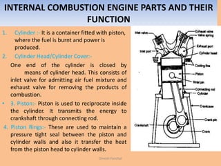
  • 98. INTERNAL COMBUSTION ENGINE PARTS AND THEIR FUNCTION 1. Cylinder :- It is a container fitted with piston, where the fuel is burnt and power is produced. 2. Cylinder Head/Cylinder Cover:- One end of the cylinder is closed by means of cylinder head. This consists of inlet valve for admitting air fuel mixture and exhaust valve for removing the products of combustion. • 3. Piston:- Piston is used to reciprocate inside the cylinder. It transmits the energy to crankshaft through connecting rod. 4. Piston Rings:- These are used to maintain a pressure tight seal between the piston and cylinder walls and also it transfer the heat from the piston head to cylinder walls. Dinesh Panchal
  • 99. 5. Connecting Rod:- One end of the connecting rod is connected to piston through piston pin while the other is connected to crank through crank pin. It transmits the reciprocatory motion of piston to rotary crank. 6. Crank:- It is a lever between connecting rod and crank shaft. 7. Crank Shaft:- The function of crank shaft is to transform reciprocating motion in to a rotary motion. 8. Fly wheel:- Fly wheel is a rotating mass used as an energy storing device. 9. Crank Case:- It supports and covers the cylinder and the crank shaft. It is used to store the lubricating oil. Dinesh Panchal
  • 100. IC ENGINE – TERMINOLOGY 1. Bore: The inside diameter of the cylinder is called the bore. 2. Stroke: The linear distance along the cylinder axis between the two limiting positions of the piston is called stroke. 3.Top Dead Centre (T.D.C) The top most position of the piston towards cover end side of the cylinder” is called top dead centre. In case of horizontal engine, it is called as inner dead centre Dinesh Panchal
  • 101. Working of a Four-Stroke Petrol Engine 1. Suction Stroke : During suction stroke, the piston is moved from the top dead centre to the bottom dead centre by the crank shaft. The crank shaft is revolved either by the momentum of the flywheel or by the electric starting motor. The inlet valve remains open and the exhaust valve is closed during this stroke. The proportionate air- petrol mixture is sucked into the cylinder due to the downward movement of the piston. This operation is represented by the line AB on the P- V diagram. 2. Compression Stroke: During compression stroke, the piston moves from bottom dead centre to the top dead centre, thus compressing air petrol mixture. Due to compression, the pressure and temperature are increased and is shown by the line BC on the P- V diagram. Just before the end of this stroke the spark - plug initiates a spark, which ignites the mixture and combustion takes place at constant volume as shown by the line CD. Both the inlet and exhaust valves remain closed during this stroke.Dinesh Panchal
  • 102. 3. Working Stroke: The expansion of hot gases exerts a pressure on the piston. Due to this pressure, the piston moves from top dead centre to bottom dead centre and thus the work is obtained in this stroke. Both the inlet and exhaust valves remain closed during this stroke. The expansion of the gas is shown by the curve DE. 4. Exhaust Stroke: During this stroke, the inlet valve remains closed and the exhaust valve opens. The greater part of the burnt gases escapes because of their own expansion. The drop in pressure at constant volume is represented by the line EB. The piston moves from bottom dead centre to top dead centre and pushes the remaining gases to the atmosphere. When the piston reaches the top dead centre the exhaust valve closes and cycle is completed. This stroke is represented by the line BA on the P- V diagram. The operations are repeated over and over again in running the engine. Thus a four stroke engine completes one working cycle, during this the crank rotate by two revolutions.Dinesh Panchal
  • 103. Working of 2-S Engine Diagram 1: The piston moves up, compressing the fuel-air mixture in the cylinder. Simultaneously, the bottom of the piston uncovers a port (the inlet port), and sucks a fuel-air charge into the bottom of the engine .It can do this because as the piston moves up, it creates a low pressure zone in the enclosed space behind it, and so the charge rushes in. When the piston gets to the top of its stroke, either the spark plug fires (in a petrol engine), or diesel-fuel is sprayed into the engine and ignites because of the extreme heat produced by the compression of air in the cylinder. Dinesh Panchal
  • 104. • Diagram 2: The spark plug fires (or diesel-fuel is injected into the cylinder), the piston is driven down, and the bottom of the piston compresses the charge below it. As the piston moves further down, it uncovers the exhaust port, and the burnt gasses begin to flow out of the cylinder. Near the bottom of its stroke, the piston then uncovers the inlet port, and the compressed charge flows into the top of the cylinder helping to drive the burnt gasses out of the cylinder. Dinesh Panchal
  • 105. Diagram 3-4: The spark plug fires (or diesel- fuel is injected into the cylinder), the piston is driven down, and the bottom of the piston compresses the charge below it. As the piston moves further down, it uncovers the exhaust port, and the burnt gasses begin to flow out of the cylinder. Near the bottom of its stroke, the piston then uncovers the inlet port, and the compressed charge flows into the top of the cylinder helping to drive the burnt gasses out of the cylinder Dinesh Panchal
  • 106. COMPARISON OF SI AND CI ENGINES 1. Works on otto cycle 2. Petrol is used as a fuel 3. It has lass compression ratio 4. Ignition takes place with the help of electric spark 5. Thermal efficiency is less 6. Initial cost is less 7. Starting is easy 8. Maintenance cost is less 9. It has carburetor to mix air and fuel 10. They are light in weight 1. Works on diesel cycle 2. Diesel is used as a fuel 3. It has more compression ratio 4. Ignition takes place due to compression 5. Thermal efficiency is more 6. Initial cost is higher 7. Starting is difficult 8. Maintenance cost is high 9. It has injector to inject fuel. 10. They are heavy in weight Dinesh Panchal
  • 107. Comparison Between 2-S and 4- S Engines 2-Stroke 1. Crank complete one revolution in in one power stroke 2. Turning effort on crank is much uniform. So lighter flywheel is required 3. It has three ports 4. It is compact and light in weight 5. It produce more noise and has more wear and tear 6. Maintenance cost is less 7. Thermal efficiency is less 8. More lubricating oil is consumed 9. Crank case is made gas tight 10. More lubricating oil is consumed 4-Stroke 1. Crank complete two revolution in in one power stroke 2. Turning effort on crank is not uniform. So heavier flywheel is required 3. It has two valves 4. It is heavier and complicated in design 5. It produces less noise 6. Maintenance cost is high 7. Thermal efficiency is high 8. Less lubricating oil is consumed 9. Crank case ins not made gas tight 10. More lubricating oil is consumed Dinesh Panchal
  • 108. Otto Cycle Fig. Shows the P-V and T-S Diagram of Otto Cycle Diesel cycle consist four processes:: 1. Process 1-2 (Isentropic Compression): In this Process piston moves from BDC to TDC and compression of air will take place adiabatically. It means there is no heat addition and removal from the gas. 2. Process 2-3 (heat addition at const. vol.): In this Process heat addition will take place at constant vol. Fuel is continuously added to air up to point 3.Dinesh Panchal
  • 109. 3. Process 3-4 (Isentropic Expansion): In this Process piston moves from TDC to BDC and expansion of air will take place adiabatically. It means there is no heat addition and removal from the gas. 4. Process 4-1 (heat rejection at const. vol.): In this Process heat rejection will take place at constant vol. Dinesh Panchal
  • 110. EFFICIENCY OF OTTO CYCLE        14v23v 21 14v2 2 23v1 1 cmcm QQRejectedHeat-addedHeatWorkdone cmQ DifferenceTemp.*Vol.Const.atHeatSpecific*QRejectedHeat 4-3processtheduringrejectedisHeat cmQ DifferenceTemp.*Vol.Const.atHeatSpecific*QInputHeat 2-1processtheduringaddedisHeat TTTT TT Mass TT Mass       Dinesh Panchal
  • 111.                 1 11- 2 1- 11 2 2 1 1 2 1 11- 2 1- 11 2 1- 22 1- 11 13 14 23 14 23v 14v 23v 14v23v 1 21 1 T V VT RatioompressionButT V VT VTVT SoProcess.isentropicis2-1Process respct.TandTof in termsTandTofvalueput theNow 1..........................................1 cm cm 1 cm cmcm edHeatSuppli Workdone Efficiency                               c c rT Cr V V V V T TT TT TT TT TT TTTT Q QQ Q W Dinesh Panchal
  • 112.                c c c cc c c r r r TT rr TT TT TT rT Cr V V V V T RationCompressio ondependentcycleottoofefficiencySo 1 1 TT 1 TT 1 11eq.inofvalueput theNow T RatioompressionBut T V VT VTVT Soexpansion.isentropicis4-3Process 1 14 1 14 1 1 1 4 14 23 14 1 43 3 4 1 3 4 41- 3 1- 44 3 1- 44 1- 33                                    Dinesh Panchal
  • 113. Diesel Cycle Fig. Shows the P-V and T-S Diagram of Diesel Cycle Diesel cycle consist four processes:: 1. Process 1-2 (Isentropic Compression): In this Process piston moves from BDC to TDC and compression of air will take place adiabatically. It means there is no heat addition and removal from the gas. 2. 1. Process 2-3 (heat addition at const. pressure): In this Process heat addition will take place at constant pressure . Fuel is continuously added to air up to point 3.Dinesh Panchal
  • 114. 3. Process 3-4 (Isentropic Expansion): In this Process piston moves from TDC to BDC and expansion of air will take place adiabatically. It means there is no heat addition and removal from the gas. 4. Process 4-1 (heat rejection at const. vol.): In this Process heat rejection will take place at constant vol. Dinesh Panchal
  • 115.        14v23p 21 14v2 23p1 cmcm Q-QRejectedHeat-addedHeatWorkdone cmQ DifferenceTemp.*Vol.Const.atHeatSpecific*RejectedHeat 4-3processtheduringrejectedisHeat cmQ DifferenceTemp.*PressureConst.atHeatSpecific*InputHeat 2-1processtheduringaddedisHeat TTTT TT Mass TT Mass       Dinesh Panchal
  • 116.                 1 11- 2 1- 11 2 2 1 1 2 1 11- 2 1- 11 2 1- 22 1- 11 1 332 v p 23 14 23p 14v 23p 14v23p 1 21 1 T V VT RatioompressionButT V VT VTVT SoProcess.isentropicis2-1Process respct.Tof in termsTand,T,Tofvalueput theNow c c Because 1...........................1 cm cm 1 cm cmcm edHeatSuppli Workdone Efficiency                                  c c rT Cr V V V V T TT TT TT TT TT TTTT Q QQ Q W Dinesh Panchal
  • 117.                                                                                      1 11 1-1 eq.efficiencyin theT,T,Tofvalueput theNow T 1 * 1 **TT 1 * 1 **T V VT T VTVT SoProcess.isentropicis4-3Process T RatioratiooffCutButT V VT VV SoProcess.isobaricis3-2Process 11 1 1 1 11 432 14 1 1 1 1 3 1 4 2 2 3 344 1 1 1 1 3 1 4 2 2 3 34 1 4 3 3 4 1 33 4 1 44 1 33 1 123 2 3 2 3 2 2 32 3 3 3 2 2 cccc c Ccc c C c Ccc c C ccc c c c c c rrTrT TT T r rT r T V V V V T r rT r T V V V V T V V T rTT V V V V T TT                          Dinesh Panchal
  • 118. QUESTION NO. 3(B) The following data pertains to C.I. Engine working on air standard diesel cycle. Cylinder bore=15cm, stroke length =-25 cm. ,clearance volume= 400 cc. Calculate air standard efficiency if fuel injection take place 5% of the stroke. Dinesh Panchal     %5959.0 77.0 85.0 7.2 1 1 155.14.1 155.1 12 1 -1 1 1 r 1 -1CycleDieselofEfficiency 55.1 400 625.441505.0400 Vol.Clearance Vol.Stroke%5Vol.Clearance Vol.Clearance Vol.offCut RatioofCut 12 400 625.4815V rRationCompressio 625.4815400625.4415VVVol.CylinderTotal 625.4415 4 25151514.3 4 VVol.Swept cc400VVol.Clearance cm25LStrokeofLengthcm;15DcylinderofBore : 4.1 4.01- c T c CT 2 S C                                      c c c C S of V ccV cc LD Given      
  • 119. Q. NO.2 An investor claims to have developed an engine that taken 105 MJ at a temp. of 400 K, rejects 42 MJ at temp of 200 K and deliver 15 KWH of mechanical work. Would you advise investing money to this engine in the market. Dinesh Panchal
  • 121. Same Compression Ratio and Heat Addition: Dinesh Panchal
  • 122. Same Compression Ratio and Heat Addition: The Otto cycle 1-2-3-4-1, the Diesel cycle 1-2-3'-4'-1 and t he Dual cycle 1-2-2”- 3”-4”-1 are shown in p-V and T-θ diagram in Fig.4.7.1 (a) and (b) respectively for the same compression ratio and heat input. From the T -s diagram, it can be seen that Area 5-2-3-6 = Area 5-2-3'-6’ = Area 5-2-2"- 3"-6" as this area represents the heat input which is the same for all cycles. All the cycles start from the same initial state point 1 and the air is compressed from state 1 to 2 as the compression ratio is same. It is seen from the T-s diagram for the same heat input, the heat rejection in Otto cycle (area 5-1-4-6) is minimum and heat rejection in Diesel cycle (5-1-4'-6') is maximum.. Consequently, Otto cycle has the highest work output and efficiency. Diesel cycle has the least efficiency and Dual cycle having the efficiency between the two. One more observation can be made i.e., Otto cycle allows the working medium to expand more whereas Diesel cycle is least in this respect. The reason is heat is added before expansion in the case of Otto cycle and the last portion of heat supplied to the fluid has a relatively short Dinesh Panchal
  • 123. Problem 1 : The compression ratio of an I.C. Petrol Engine is 4 .Find the air standard efficiency. Problem 2: The efficiency of Otto cycle is 505 .What will be the compression ratio if ϒ=1.4 Problem 3: An engine working on Otto cycle has a cylinder dia. Of 18 cm and a stroke of 25 cm. The clearance volume is 1400 cub. Cm. .Find the air standard efficiency of the engine. Problem 4: In an engine working on Otto cycle , the pressure and temp. at the beginning of the adiabatic compression are 1 bar and 30 0C Respectively. Calculate the compression ratio and also calculate the pressure and temperature at the end of the compression if air standard efficiency is 45% and ϒ=1.4 Problem 5 : An engine working on Otto cycle has pressure and temperature at the beginning of the adiabatic compression as 1 bar and 500 respectively. The pressure at the end of the compression is 12 times that at the beginning,. If the temperature of the air at the end of the heat supplied during constant vol. is 20000C . Calculate 1. Compression Ratio 2. Efficiency 3. Heat Supplied/Kg OF Air 4. Work done/Kg of Air 5. Pressure at the end of the adiabatic Compression. Dinesh Panchal
  • 124. Problem 6. : Calculate the efficiency of diesel cycle whose compression ratio is 18 and cut off ratio is 2.133. Assume ϒ=1.4 Problem 7. : Calculate the air standard efficiency of a diesel cycle whose compression ratio is 14. The cut off takes place at 65 of stroke. Assume ϒ=1.4 Problem8 : Following data relates to the diesel engine. Stroke Length = 30 cm, Diameter of the cylinder = 20 cm, Clearance Volume = 800 Cubic cm, Cut off ratio take place at 55 of the stroke . Calculate the Compression Ratio, Cut off Ratio and Air Standard Efficiency. Dinesh Panchal
  • 125. GAS TURBINE It is a machine which produces power by utilizing the K.E. Obtained by burnt gases under pressure and undergoes a pressure drop in a nozzle. Dinesh Panchal
  • 126. GAS TURBINE It is a machine which produces power by utilizing the K.E. Obtained by burnt gases under pressure and undergoes a pressure drop in a nozzle The basic component of Gas Turbine are shown in fig. 1. Air compressor 2. Combustion chamber 3. turbine Dinesh Panchal
  • 127. WORKING OF GAS TURBINE In gas turbine air is obtained from the atmosphere and compressed in the compressor. Compression may by 4 to 6 .The compressed air then passed in to the combustion chamber . , where it is heated. The hot air is then made to flow over the moving blade of gas turbine. Which gives the rotational motion. During this process air gets expanded and finally exhausted to the atmosphere. Thermal efficiency of gas turbine varies from 25 to 35%. Fuel used in gas turbine are oil, natural gas, coal ect. Dinesh Panchal
  • 128. Types of Gas Turbines 1. Open Cycle gas Turbine 2. Closed Cycle Gas Turbine Open cycle gas turbine:- it is the simplest form and consist compressor , combustion chamber and a gas turbine which drives the generator and compressor. In this turbine air is sucked from the atmosphere and then compressed isentropic ally .This compressed air is heated in the combustion chamber and finally made to flow over the blade of the turbine and this hot air gives the drive to the blades. Dinesh Panchal
  • 129. CLOSED CYCLE GAS TURBINE A closed-cycle gas turbine is a turbine that uses a gas (e.g. air, nitrogen helium, argon etc.) for the working as part of a closed thermodynamic system. Heat is supplied from an external source. Such recalculating turbines follow the Brayton Cycle. The diagram shows the closed cycle gas turbine. In this turbine air is compressed isentropic ally in the compressor and then passed in to the heating chamber. The compressed air is heated with the help of some external source and ten made to flow over the turbine blade . The gas while flowing over the turbine blade ,gets expanded. From the turbine , the gas is passed over to the cooling chamber where it get cooled at constant pressure with the help of circulating water to original water. Now the air is made to flow in to the compressor again . Applications : 1. Aviation 2.Central Electric Generation Station 3.Used in Combined Cycle Power Station Dinesh Panchal
  • 130. Comparison Between Gas turbine and I.C. Engines 1. Balancing is perfect 2. Pressure used is low 3. Installation and running cost is less 4. Running speed is high 5. Maintenance cost is less 6. Lubrication and ignition system is simple 7. Efficiency is higher. 8. Cooling system is simple. 9. Torque produced is uniform. 10. Starting is not simple. 11. Suitable for air craft. 12. Exhaust is free from smoke and less polluting. 1. Balancing is not perfect 2. Pressure used is high 3. Installation and running cost is more 4. Running speed is low 5. Maintenance cost is more 6. Lubrication and ignition system is complicated. 7. Efficiency is lower. 8. Cooling system is not simple. 9. Torque produced is not uniform. 10. Starting is simple. 11. Less Suitable for air craft. 12. Exhaust is more polluting. Dinesh Panchal
  • 132. Machine:- it is a device that is capable of doing useful work. It receive energy in some available form and uses that energy in to useful work. The energy may be electrical, mechanical, thermal, chemical. The machine may be simple or compound. Simple machine:- simple machine has only one point of application of effort and one point for load Examples:- • Lever • Pulley and pulley system • Wheel and axle • Inclined plane • Screw jack 2. Compound Machines:- are those machines which has more than one point of application of effort and more than one point of applying the load.Dinesh Panchal
  • 133. Lifting Machine:- it is a device with the help of which we are able to lift the heavy loads by applying the less effort. Examples :- • Lever • Pulley and pulley system • Wheel and axle • Inclined plane • Screw jack Dinesh Panchal
  • 134. Some Definitions Load: - a machine is used to lift the load or overcome to some resistance. The weight is to be lifted by the machine is called Load. It is denoted by W Effort: - The force required to lift the load or to overcome the resistance is called Effort . It is denoted by P Input :- input of a machine is the work done on machine. It is the product of effort and distance moved by effort Input=Effort x Distance moved by Effort = P X y Output :- output of a machine is the work done by the machine. It is the product of Load and distance moved by Load Output=Load x Distance moved by Load =W X x Mechanical Advantage:- It is defined as the ratio of the load to the effort applied denoted by M.A. Velocity Ratio :- It is defined as the ratio of the distance moved by effort to the distance moved by load denoted by V.R. P W AppliedEffort LiftedLoad M.A.AdvantageMechanical  x y  LoadbyMovedDistance EffortbyMovedDistance RatioVelocityDinesh Panchal
  • 135. Efficiency of Machine:- it is defined as the ratio of output of a machine to input of a machine. It is denoted by η η = Output of Machine/ Input of Machine = W X x / P X y = M.A. / V.R. So efficiency of a machine is the ratio of Mechanical Advantage to Velocity Ratio. Ideal Machine:- A machine whose efficiency is 100% is called an ideal machine. It has equal input and output Ideal effort :- is the effort required to lift the load by the machine, assuming the machine to be ideal. Dinesh Panchal
  • 136. LAW OF MACHINE The law of machine may be defined as by an equitation which gives the relationship between the load lifted (W) and the effort applied (P) This is generally a straight line which does not pass through the origin. The law of machine is given below P=mW+C C – intercept OA , m- Slop of AB P- Effort Applied, W – Load Lifted For an ideal machine the line passes through the origin Max. M.A.=1/m Max. Efficiency=Max. M.A./V.R. m=(P2-P1)/ (W2-W1) Y intercept P1=Mw1+C Fig. A O B C Effort DLoad E F m 1 For Actual Machine ForIdealMACHINE Dinesh Panchal
  • 137. REVERSIBILITY OF A MACHINE If a machine is capable of doing work in the reverse direction after the removal of the Effort called reversible machine. Let P be the effort required to lift the load W . Now if P is removed W may fall. It is called reversible machine. Reversibility of a machine dependent on its efficiency, if the efficiency is less than 50% it will be self locking and if it is greater than 50% it is reversible. CONDITION FOR REVERSIBILITY : - W- Load Lifted by Machine P- Effort Applied to Lift the Load y- Distance moved by Effort X- Distance moved by Load Input = output + Work done by Friction = Output + Work done to overcome to Friction Work done Lost in Friction = Input -Output = P . y - W . xDinesh Panchal
  • 138. When effort is removed , the load can start moving down if it can overcome the friction resistance(i.e. Input-Output) Hence the condition for the reversibility is the output of the machine is more than that the work lost in friction when effort is removed i.e. P=0 Output > Work Lost in Friction Output > Input-Output W . x > P . y - W . x 2W . x > P . y W/P . x/y >1/2 M.A./V.R. >1/2 η > ½ η > 50% Dinesh Panchal
  • 139. • QUESTION NO. 7 In a lifting machine an effort of 16N is required to lift the load of 800 N at an efficiency of 60% . The same machine require an effort 25 N to lift the load of 1500 N. Determine the Law of Machine and calculate max. M.A. and efficiency. • Ans: %9393. 33.83 7.77 R.V. M.A.Max. Max. 7.77 9 700 m 1 M.A.Max. :AdvantageMechanicalMax. 5.710.0128wP :MachineofLaw 71.5 7 40 C;0128.0 700 9 m (ii)and(i)equatationtheSolve ......(ii)..........C1500m25 ....(i)..........C800m16 2and1CasefromWPandofvaluePut the CmWP :MachineofLaw N800WLiftedLoad 16PappliedEffort:2Case 33.83 6.0 16/800M.A. V.R. V.R. M.A. N800WLiftedLoad 16PappliedEffort:1Case 60% : 2 2 1 1                  N N Given Dinesh Panchal
  • 140. • QUESTION NO. 7 In case of lifting machine, effort required to lift the load 50N and 80N were 12N and 18 N.If the velocity ratio of the machine was 6 . Determine (i) Law of machine (ii) Efficiency of the machine and the effort lost in friction at 50 n load (iii) Max. efficiency expected from the machine • Ans: %8383. 6 5 R.V. M.A.Max. Max. 5 2.0 1 m 1 M.A.Max. :AdvantageMechanicalMax. %707.0 6 2.4 V.R. M.A. (Given)6R.V.And2.4 12 50 M.A. 1220.250P 50WloadAt 2W2.0P :MachineofLaw 2C;20.0 30 6 m (ii)and(i)equatationtheSolve ......(ii)..........Cm0818 ....(i)..........Cm0512 2and1CasefromWPandofvaluePut the CmWP :MachineofLaw N80WLiftedLoad18PappliedEffort N05WLiftedLoad12PappliedEffort 60% : 3 11 11                  N N N Given Dinesh Panchal
  • 141. WHEEL AND AXLE It consist of two cylinders A and B of different diameters rotating on the same axis. The bigger cylinder A is called wheel and the smaller one B is called axle. Wheel had diameter D and axle diameter is D. a string is wound round the axle. The one end of the string is fixed to the axle and attached to the load W. Another string is wound round on the wheel. One end of the string is fixed to wheel and effort is applied on the other end. These two strings are wound in opposite directions, so that one rope wrap and other unwrap on rotation. Dinesh Panchal
  • 142. D – Dia of wheel d – Dia of Axle W – Load Lifted P – Effort Applied Distance moved by Effort in one revolution = ΠD Distance moved by Load in one revolution = πd PD Wd RV AM Efficiency d D      d D P W .. .. P W AppliedEffort edWeightLift M.A. d D LoadbymovedDistance effortbymovedDistance V.R.    Dinesh Panchal
  • 143. Differential Wheel and Axle It has one wheel and two axle. It consist of wheel A of Diameter D , Axle B of Diameter of d1 and axle C of Diameter d2 . All three are keyed to the same shaft. One string is wound round the wheel A . Another end of this string is for applying effort. Second string is wound round the axle B, which after passing rounds to the pulley is wound round on axle C in the opposite direction. So that when the string on wheel A unwound, The string on axle C should also unwind but wound on axle B. Dinesh Panchal
  • 144. W – Load Lifted P – Effort Applied D – Diameter of Wheel d1 – Diameter of Axle B D2 – Diameter of Axle C Distance moved by Effort in one revolution = Πd Length of string unwound from cylinder C= πd2 Length of string wounds from cylinder B= πd1 Length of string wound in one revolution = πd1- πd2 Displacement of Load = (πd1- πd2)/2        2121 2121 D d-d P W .. .. P W M.A. D d-dd LoadbymovedDistance effortbymovedDistance V.R. ddP WD RV AM Efficiency D d            Dinesh Panchal
  • 145. Differential Pulley Block It consist of three pulleys A, B and C. Pulleys A and B having Diameters D, d respectively which rotates about a common axis through O. Pulley C is a movable pulley and load is attached to this pulley. A single string passes around the pulleys as shown in fig. The string first passes round the pulley A then round pulley C and then finally round the pulley B. Effort is applied at the end of the string passing round the pulley A . Dinesh Panchal
  • 146. W – Load Lifted P – Effort Applied D – Diameter of Pulley A d1– Diameter of Pulley B When pulley makes one revolution, it moves downwards by an amount of .Then string passes over the pulley B and moves downwards by an amount `So string passes over the pulley C is = Displacement of Effort P in one Revolution of Pulley A = Length of string released by pulley B = Dinesh Panchal
  • 147.         DP dDW dD D RV AM Efficiency dD D dD D 22 P W .. .. P W AppliedEffort LiftedWeight M.A. 2 2 LoadbymovedDistance effortbymovedDistance V.R.                   Dinesh Panchal
  • 148. Worm and Worm Wheel It consist of a square threaded screw B called worm and a toothed wheel C known as worm wheel. The worm B is in mesh with worm wheel; C and their axis are at right angle the each other. On the axis of worm B , effort wheel A of Diameter D is attached , over which a rope is wounded. The effort is applied at one end of rope. On the axis of the wheel c, a small pulley or a load drum having diameter d provided over which a rope is wounded and one end of the rope is used to attach load. B C A d Dinesh Panchal
  • 149. W – Load Lifted P – Effort Applied D – Diameter of Effort Wheel A r=d/2Diameter of load Drum T – Number of teeth on worm wheel C Single Start: Distance moved by effort in one revolution of effort wheel = π D Load Drum will turn in one revolution of worm B = 1/T Revolution Distance moved by Load = 2π r X 1/T A B C D P W M.A. d DT d DT 1 LoadbymovedDistance effortbymovedDistance V.R.        T d D Dinesh Panchal
  • 151. Single Purchase Winch Crab It consist of an effort axle having a small toothed wheel known as pinion with teeth T1 on it. The pinion gear is the driving gear and it is in mesh with the larger toothed gear known as spur gear having teeth T2 .It is a driven gear. This spur gear is connected to the load drum. When effort is applied to the effort axle, the effort wheel and the pinion wheel attached to it start to move. As the pinion wheel is coupled with spur gear, later also rotates in reverse direction Dinesh Panchal
  • 152. L – Length of Arm Lever W - Load Lifted P – Effort Applied d – Dia . Of Load Drum T1 – No. of teeth on pinion T2 – No. of teeth on Spur Gear In one revolution of lever, pinion will complete one revolution. So distance moved by Effort in one revolution of lever = 2π L In one revolution of lever spur wheel will complete T1/T2 revolution. So distance moved by Load in one revolution of lever =T1/T2 X πD L P W M.A. DT 2LT D LT22 LoadbymovedDistance effortbymovedDistance V.R. 1 2 1 2 2 1    T T T D L     Dinesh Panchal
  • 154. Double Purchase Crab Winch It is the extended version of single purchase crab winch. Velocity ratio of a crab winch is increased by providing another axle with pair of pinion and spur wheel. As shown in Fig. L – Length of Arm Lever W - Load Lifted P – Effort Applied d – Dia . Of Load Drum T1 – No. of teeth on pinion of effort wheel T2 – No. of teeth on Spur wheel of intermediate wheel T3– No. of teeth on pinion of intermediate axle T4 – No. of teeth on Spur wheel of load axle In one revolution of lever pinion will complete one revolution. Dinesh Panchal
  • 155. So distance moved by Effort in one revolution of lever = 2π L In one revolution of effort wheel intermediate axle will complete T1/T2 No of revolutions made by spur wheel attached to load axle = T1/T2 X T3/T4 42 31 31 42 31 42 31 42 4 3 2 1 T2LPT TWDT 2.. .. P W M.A. D LT2 D LT22 LoadbymovedDistance effortbymovedDistance V.R.      TDT TLT P W RV AM Efficiency TT T TT T T T X T T D L      Dinesh Panchal
  • 156. Simple Screw Jack In screw jack , a square threaded screw is used to raise the heavy loads by applying smaller effort. It consist of a nut, which form the body. Screw with square thread and handle attached to screw thread. The load lifted is placed on the screw head. The effort P is applied at end of the handle attached to the screw. Pitch of screw = p Distance moved by effort in one revolution of handle = 2π L Distance moved by the Load = p Dinesh Panchal
  • 158. Differential Screw Jack Fig shows the differential screw jack. It gives more velocity ratio . So it require less effort to lift the load. It consist of two screws B and C threaded on both inner and outer side passes through a nut, while small screw C threaded only on the outer side meshes through the inner side of screw B. p1 – Pitch of thread of spindle B p2 – Pitch of thread of spindle C Distance moved by effort in one revolution of screw C = 2π L Distance moved by load in one revolution of screw C = p1-p2 Dinesh Panchal
  • 159.       LP2 pW 2.. .. P W M.A. 2 LoadbymovedDistance effortbymovedDistance V.R. 21 21 21     p pp L P W RV AM Efficiency pp L         Dinesh Panchal
  • 160. • QUESTION NO. 5 In a simple screw jack the pitch of the screw is 10 mm and the length of the handle is 450mm . Find the velocity ratio. If an effort of 25 N applied on the handle can lift a load of 3KN . Find efficiency of the jack. Also calculate the amount of effort wasted in friction. • Ans: J40.79.58x70.65 )-(1supplikedEnergyfrictionintedEnergy was 70.65 1000 45025xx2π effortbymovedDistanceEffort xmachinetheSuppliedEnergy %5.42 2.282 120 .. .. 120 25 3000 .. 2.282 10 2x3.14x450 2 tan tan .. 3LiftedLoad 25NappliedEffort 450mmhandletheofLength 10mmScrewtheofPitch :Given                 RV AM P W AM p L oadcemovedbyLDis heEffortcemovedbytDis RV KNW P L p Dinesh Panchal
  • 161. Problem 1: In a simple machine, whose velocity ratio is 30, a load of 2400 N is to be lifted by an effort of 150 N and a load of 3000N is lifted by an effort of 180 N . Find the law of machine and calculate the load that could be lifted by a force of 200 N. Calculate (i) Amount of Effort wasted in overcoming the friction (ii) M.A. (III) Efficiency Problem 2. : In a differential wheel and axle the diameter of axles are 150mm and 70mm and load 250N is raised by an effort of 10N at an efficiency of 80% . Find the diameter of the wheel. Problem 3: In an differential wheel axle assembly, the diameter of the wheel is 150mm and that of axles are 50mm and 30 mm respectively. If the machine has an efficiency of 65% find the effort required to lift the load of 2500 N .Calculate the no. of revolution made by the machine in lifting the load by a distance of 150mm. Dinesh Panchal
  • 162. Problem 4 : The western differential pulley consist of a lower block and upper block. The upper block has two pulleys of diameter 230mm and 210 mm. If the efficiency of the machine is 505 .Calculate the effort required to Raise the load of 160 N. Problem 5 : In a double threaded worm and worm wheel the no. of teeth on the worm wheel is 25. The diameter of the effort wheel and the load drum are 500mm and 150mm RESPECTIVELY. Calculate the velocity ratio and efficiency of the machine if it require an effort of 300N to lift a load of 3200 N. Problem 6.: Following are the specifications of single purchase winch crab. Dia. Of Load Drum=200mm, Length of Lever Arm=L= 1.2m, No. of Teeth on Pinion = T1=10 , No. of Teeth on Pinion = T2=100. Find the velocity ratio of the . On this machine effort of 100N and 160 N are require to lift the load of 3KN and 9 KN respectively .Find the law of machine and efficiency. Dinesh Panchal
  • 163. Problem 7 : In a double purchase crab winch , the pinions have 15 and 20 teeth, while the spur wheels have 45 and 40 teeth. The effort handle is 400 mm long while the effective diameter of the drum is 150mm .If the efficiency of the winch is 40% , what load will be lifted by an effort of 250 N applied at the end of the handle. Problem 8: A screw Jack has a square threaded screw of 5cm did and 1cm pitch. The coefficient of friction at the screw thread is 0.15. Find the force required at the end of the 70 cm long handle to raise a load of 2000N . What is the force required if screw jack is considered to be an idle machine. Problem 9: A screw jack has square threads 50mm mean dia. And 10mm pitch. The load on the jack revolve with the screw . The coefficient of friction at the screw thread is 0.05 . Find the tangential force at the end of 300mm lever to lift load of 6000N. State whether the jack is self locking. If not find the torque must be applied to keep the load from descending. Dinesh Panchal
  • 165. REFRIGERATION AND AIR CONDITIONING Refrigeration may be defined as the process of achieving and maintaining a temperature below that of the surroundings, the aim being to cool some product or space to the required temperature. Important application: 1.preservation of food and products Refrigeration systems are 2. Water cooler 3. Refrigerator 4. Cold storage 5. Ice cream manufacturer. Dinesh Panchal
  • 166. Air Conditioning refers to the treatment of air so as to simultaneously control its temperature, moisture content, cleanliness, odor and circulation, as required by occupants, a process, or products in the space. Applications: 1. Buildings 2. Homes 3. Offices 4. Automobiles 5. railways Dinesh Panchal
  • 167. Rating of Refrigeration Machine: Means the cooling effect produced by the machine. Unit for measurement of cooling is Ton of known as ton of refrigeration One ton of refrigeration is defined as the amount of refrigeration effect produced by uniform melting of one ton of ice from and at 0 degree in 24 hours. 1TR=1000X335KJ in 24 Hours = 232.6KJ/min But in actual practice one ton of refrigeration is 210 KJ/Min or 3.5 KJ/Sec Dinesh Panchal
  • 168. Coefficient of Performance: It is defined as the ratio between refrigeration effect and work done on the refrigerant 12 1 1 e e Workdone ExtractedHeat ... C.O.P.lTheoretica C.O.P.Actual C.O.P.Relative unity.thanmorealwaysisC.O.P. re.temperatulowatthebodyfrom extractedheatooamounttheisEffectingRefrigerat KJ/Secinworkdonetheis-W KJ/SecinEffectingRefrigerattheisRWhere W R Workdone EffectingRefrigerat ... QQ Q W Q POC POC       Dinesh Panchal
  • 169. Question no. 1(c) A household refrigerator maintain the refrigerated space at 3 C by removing the heat from it at a rate of 4KW. The power required to run the refrigerator is 1.5KW. Determine the C..O.P. of refrigerator. Ans: Dinesh Panchal 666.2 5.1 4 Workdone RemovedHeat C.O.P KW5.51.54gSurroundinthetosuppliedHeat 4QRemovedHeat 5.1 3TempoLower 2 0      KW KWWorkdone C
  • 171. SIMPLE VAPOUR COMPRESSION CYCLE: It is the most commonly used refrigeration cycle. In this cycle there are four fundamental processes are required to complete one cycle 1. Compression 2. Condensation 3. Expansion 4. Vaporization Dinesh Panchal
  • 172. 1. Compression The low pressure and temp vapor in dry state enters in the compressor during the suction stroke of the compressor. During compression stroke, it compresses the vapors isentropic ally, hence temp. and pressure increases. 2. Condensation: After compression the high pressure and temp refrigerant vapors enters in the condenser , heat is removed from the refrigerant and refrigerant temp. decreases in the condenser and refrigerant returned to the liquid state. Dinesh Panchal
  • 173. 3. Expansion : After condensation, the liquid refrigerant is stored in a receiver tank. From the receiver tank ,it passes through an expansion valve where it get throttled down and allow to expand at low pressure . Here the high pressure liquid converts into the low temp vapors. 4. Vaporization: The low pressure refrigerant vapor after expansion in the expansion valve enters in to the evaporator or refrigerated space , where heat is absorbed by it from the refrigerated space .After that these vapors enters in the compressor for compressor .the same process repeats again and again Dinesh Panchal
  • 174. Fundamentals of Air Conditioning : 1. Dry Bulb Temp : It is the temp. of moist air as measured by stranded thermometer. 2. Wet Bulb Temp. : If the unsaturated air flows over a thermometer with a wet cloth over the bulb of the thermometer. And the temp. recorded will be less than the DBT .This temp. is known as WBT. 3. Relative Humidity : it is defined as the ratio of actual mass of water vapor in a given vol. of moist air to mass of water vapour in the same vol. of saturated air at the same temp and pressure. It is denoted by φ PressureandTemp.sameatAirSaturatedofvol.samein theVapourWaterofMass AirMoistofgiven vol.inourwater vapofMassActual  Dinesh Panchal
  • 175. 4. Humidity Ratio (W): It is the ratio of mass of water to the mass of dry air in a given vol. 5. Absolute Humidity: Water vapor in the air is called Humidity. The absolute Humidity of the air at any given condition is the mass of water vapors per unit vol. of air at that condition. 6. Due Point Temp : If an unsaturated moist air is cooled at constant pressure , then the temp. at which the moister in the air begin to condense is known as dew point temp. of air (DPT) vt v a a a v pp p TR Vp T m m w    622.0R p AirDryofMass VapourwaterofMass V v Dinesh Panchal
  • 176. Degree of Saturation: The degree of saturation is the ratio of the Humidity Ratio W to the Humidity Ratio of a saturated mixture Ws at the same temp and Pressure. W= Humidity Ratio Ws= Water vapour in the same mass and pressure of dry air when it is saturated at the same temp. ptSW W ,1  Dinesh Panchal
  • 177. Refrigerant: it is a heat carrying medium , which during the cycle absorb the heat at low temp and release the heat at high temp. Ammonia and sulphur di-oxide are used as are refrigerant in past. Most common refrigerants are 1. Freon 12 – dichloro difloro methane-CCl2F - R-12 OR F-12 . It is harmful gas for ozone layer. 2. Ammonia is used for large industrial plants. 1.Halocarbon Compounds (A) R-11 Trichloromonofloromethane CCl3F4 (b) R-12 dichlorodifloro methane CCl2F ( c) R-13 Monochlorodtrifloro methane CClF3 (d) R-22 Monochloroddifloro methane CHClF2 2. Inorganic Compounds: (a) R-717 Ammonia NH3 (b) R-718 Water H2O ( c) R-729 Air (d) R-744 Carbon dioxide CO2 3. Hydrocarbon : (a) R-50 Methane CH4 (b) R-170 Ethane C2H6 Dinesh Panchal
  • 178. Refrigerant Classification 1.Halocarbon Compounds (A) R-11 Trichloromonofloromethane CCl3F4 (b) R-12 dichlorodifloro methane CCl2F ( c) R-13 Monochlorodtrifloro methane CClF3 (d) R-22 Monochloroddifloro methane CHClF2 2. Inorganic Compounds: (a) R-717 Ammonia NH3 (b) R-718 Water H2O ( c) R-729 Air (d) R-744 Carbon dioxide CO2 3. Hydrocarbon : (a) R-50 Methane CH4 (b) R-170 Ethane C2H6 Dinesh Panchal
  • 180. Psychometric Chart 1. Dry Bulb Temp. Lines : The dry bulb temp lines are vertical to the ordinate and uniformly spaced . The Temperature range of these lines is from -60C To 450C. 2. Specific Humidity : The specific humidity are horizontal lines and uniformly spaced. The moister content range is 0 to o.030 Kg/Kg of dry air. Dinesh Panchal
  • 181. 3. Dew point temperature: The due point temp. lines are horizontal and non uniformly spaced. At any point on the saturation curve, the dry bulb and dew point temp. are equal 4. Wet bulb temp. lines: The wet bulb temp lines are inclined straight lines and non uniformly spaced . At any point on the saturation curve, the dry and wet bulb temp are equal. 5. Enthalpy lines: Enthalpy or total heat lines inclined straight lines and uniformly spaced. These lines are parallel to the wet bulb temp lines . Dinesh Panchal
  • 182. 6. Specific Vol. Lines: The specific vol. lines are obliquely inclined straight lines and uniformly spaced. 7. Relative Humidity Lines : The relative humidity lines are curved lines and follow the saturation curve and drawn with 10%, 20%, 30% and up to 100% Dinesh Panchal
  • 184. Introduction # Power is transmitted from one shaft to another shaft by means of 1. belt 2. Ropes 3. chains 4. Gears # For large distance between the shaft belt rope and chains are used. # But gears are used for small distance. # To decide the type of drive the following factors are considered 1. Angular position of the shaft 2. Distance between the shaft 3. Direction of motion 4. Requirement of sped 5. Type of maintenance required. 6. Power to be transmitted 7. Positive drive requirement Dinesh Panchal
  • 185. Belt and Rope Drive : The flexible wrapping connectors are used for transmitting the power from one shaft to another shaft. When the thickness of the connector is small as compared to its width then it is called belt . If the cress section is approximately circular then it is called rope drive. The rope and belt kept in tension so that there is no slip between the pulley and the connector. In case of rope grooved pulleys are used. Types of belts : 1. flat belt : A belt having the rectangular cross section is known as flat belt. It is used mostly in factories for moderate power transmission. The distance between the pully not more than 8 meter Dinesh Panchal
  • 186. 2. V- belt : The belt having the trapezoidal cross section is known as V belt. It is used in factories and workshops. It is used to transmit great power when the distance between the pulleys is small. The belt does not touch the bottom of the groove. 3. Rope belt : The belt having the circular cross section is known as rope or circular belt. It is must have high coefficient of friction. They can be classified according to the belt material # Leather Belt # Cotton Belt # Rubber Belt Dinesh Panchal
  • 187. Types of Flat Belt : 1. Open Belt Drive 2. Crossed Belt Drive 3. Quarter Turn Belt Drive 4. Belt Drive with idle pulley 5. Compound Belt Drive 6. stepped pulley drive 7. Fast and loose pulley drive Dinesh Panchal
  • 189. Rope belt : The belt having the circular cross section is known as rope or circular belt. It is must have high coefficient of friction. When the large amount of power are to be transmitted over a considerable distance then rope are used. The flat belt drive is limited to a distance of 8 m and for large power transmission. The frictional grip of the rope drive is more as compared to the V belt. The are used in well drawing, spinning mills . They are of two types # Fiber Rope # Wire Rope Advantages of Rope Drive : # They have low cost # They have high mechanical efficiency # The outdoor condition affect them very little. # The shaft may be out of strict alignment. #The have smooth ,steady and quite operation. Dinesh Panchal
  • 190. Chain Drive : A chain drive consist of endless chain running over two sprockets driver and driven. These are used where positive action is required. The velocity ratio is constant. These drives are use when the distance between the shafts are very short. The are used in bicycles, motorcycles, agricultures machinery. Advantages : # It is positive drive. # It can be employed between short and long centre distance. # Less load on shaft. # Give constant velocity ratio. # They are compact in size. Disadvantages : # High wear and tear # Cost is high # Drive needs lubrication. Dinesh Panchal
  • 191. Types of Chain Drive : 1. Hoisting Chains 2. Conveyor Chains 3. Power transmission Chains Dinesh Panchal
  • 192. Gear Drive : Gear are toothed wheels used to transmit motion between two shafts, when the centre between the shaft is very small. Gear is positive drive which give exact velocity ratio. Intermediate link or connector .Two bodies have either rolling or sliding contact. They do not use When the teeth are provided on the internal surface called internal gears and if they are provided on the outer surface called external gears. They are used in watches , cutting machine tools, automobiles, rolling mills. Diagrams Dinesh Panchal
  • 193. Advantages : # They are compact in size. # They Give positive drive # They have high efficiency # They can be used for precise timing. # They can transmit large power. # Maintenance cost is less. # They can drive loads without shock at speed up to 20 m/sec Disadvantages : # They are not suitable for large distance. # Manufacturing is complex # If there is error in manufacturing they gives undesirable noise Dinesh Panchal
  • 194. Classification of Gears : 1. According to position of axis (i) Parallel shafts (a) Spur Gear (b) Spur Rack and Pinion (c) Helical Gear (d) Double Helical Gear (e) Herring Bone Gear Dinesh Panchal
  • 195. (ii) Intersecting Shafts (a) Straight bevel gear (b) Spiral bevel gear (iii) Non Intersecting Shafts and non Parallel shafts (a) Hypoid gear (b) Spiral bevel gear (c) Worm Gear Dinesh Panchal
  • 196. 2. According to peripheral velocity of gears (i) Low velocity (ii) Medium velocity (iii) High velocity 3. According to type of gearing (i) Internal Gearing (ii) External Gearing 4. According to shape of teeth of gears (i) Straight teeth gear (ii) Inclined teeth gear (iii) Curved teeth gear Dinesh Panchal
  • 197. Gear Nomenclature : 1. Pitch Circle : It is the imaginary circle by which pure rolling action , would give the same motion as the actual gear 2. Pitch Circle Diameter : It is the diameter of pitch circle 3. Pitch Point : It is the common point of contact Between two pitch circles 4. Pressure Angle : It is the angle between the common normal to the two teeth at the point of contact and the common tangent at the pitch circle. It is usually denoted by Ф. Pressure angle are 14.50 and 200. Dinesh Panchal
  • 198. 5. Addendum: It is the radial distance of a tooth from the pitch circle to the top of tooth. 6. Dedendum: It is the radial distance of a tooth from the pitch circle to the bottom of the tooth. 7. Addendum Circle: It is the circle drawn through the top of the and concentric with the pitch circle. 8. Dedendum Circle: It is the circle drawn through the bottom of the teeth. It is also called root circle. Dinesh Panchal
  • 199. 9. Circular Pitch : It the distance measured on the circumference of the pitch circle from a point of one tooth to the corresponding point on the next tooth. It is denoted by pc . pc=∏D/T Where D is the pitch circle and T is the no. of teeth 10. Diametrical Pitch : It is the ratio of no. of teeth to the pitch circle diameter in mm .It is denoted by pd. pd.=T/D 11. Module : It is the ratio of pitch circle diameter in mm to the no. of teeth. It is denoted by m. m=D/T 12. Clearance : It is the radial distance from the top of the tooth to the bottom of the tooth in meshing gear. Dinesh Panchal
  • 200. 13. Total Depth: It is equal to the sum of addendum and dedendum. 14. Working Depth: It the radial distance from the addendum circle to the clearance circle. It is equal to the sum of the addendum of two meshing gears. 15. Tooth Thickness: It is the width of tooth measured along the pitch circle. 16. Tooth Space: It is the width of space between the two adjacent teeth measured along the pitch circle. 17. Backlash : It is the difference between the tooth space and tooth thickness, as measured along the pitch circle. 18. Face of tooth : It is the surface of the gear above the pitch circle. 19. Flank of Tooth : It is the surface of gear below the pitch circle. Dinesh Panchal
  • 201. Gear trains : It is the combination of two or more than two gears to transmit the motion fro driving shaft to the driven shaft. Types of gears trains: (i) Simple Gear Train (ii) Compound Gear Train (iii) Reverted Gear Train (iv) Epicyclical Gear Train (i) Simple Gear Train : It is a series of gears capable of receiving and transmitting the motion from one to another gear. Speed Ration is the ratio of speed of driver to the speed of driven. Train value is the ratio of speed of driven to the speed of driver 2 1 1 2 1 2 2 1 N N ValueTrain N N RatioVelocityRatioSpeed T T T T   Dinesh Panchal
  • 202. (ii) Compound Gear Train : Compound gear train consist of series of gears connected in such a way that two or more gears rotate around an axis with same angular velocity. Dinesh Panchal
  • 203. (iii) Reverted Gear Train : If the axis of driver shaft and the driven shaft is co axial then it is known as reverted gear train. Dinesh Panchal
  • 204. (iii) Epicyclical Gear Train: if one of the gear is rotating over other gear . Epic means over and cyclic means around. There is an arm connecting these two gears. Dinesh Panchal
  • 205. • CLUTCH A Clutch is a machine member used to connect the driving shaft to a driven shaft, so that the driven shaft may be started or stopped at will, without stopping the driving shaft. A clutch thus provides an interruptible connection between two rotating shafts Clutches allow a high inertia load to be stated with a small power. A popularly known application of clutch is in automotive vehicles where it is used to connect the engine and the gear box. Here the clutch enables to crank and start the engine disengaging the transmission Disengage the transmission and change the gear to alter the torque on the wheels. Clutches are also used extensively in production machinery of all types Dinesh Panchal
  • 206. Clutch : A Clutch is a machine member used to connect the driving shaft to a driven shaft, so that the driven shaft may be started or stopped at will, without stopping the driving shaft. A clutch thus provides an interruptible connection between two rotating shafts. Clutches allow a high inertia load to be stated with a small power. A popularly known application of clutch is in automotive vehicles where it is used to connect the engine and the gear box. Here the clutch enables to crank and start the engine disengaging the transmission Disengage the transmission and change the gear to alter the torque on the wheels. Clutches are also used extensively in production machinery of all types Dinesh Panchal
  • 207. Requirement of clutch : # For Transmission of torque under different conditions # For transmitting the power gradually. # Clutch should dissipate the large amount of heat. # Clutch should be dynamically balanced. # There should be suitable mechanism with in the clutch to reduce the noise. # Size of clutch should be as small as possible. # The rotating parts of clutch should have minimum inertia. # Clutch design should be such that it is easy to operate. Function of clutch : # To engage the engine power to the gear box. # To disengage the engine power to the gear box. # To provide the smooth and gradual operation to take up the load without jerk. # To help in shifting the gear in the gear box. Dinesh Panchal
  • 208. Principle of clutch : Suppose there are two discs as shown ion fig. Initially the disc A is rotating at a speed N rpm and disc B is stationary. It means clutch is not engaged. Now load W is applied on Disc B to engage it with disc A then the force of friction comes in to play between the dices and the disc B will start rotate. If the load is increased, the speed of B will increase and at last will attain the speed equal to the speed of A. This is the principle of clutch. Dinesh Panchal
  • 209. Types of clutches Clutch Dog Clutch Friction Clutch Cone Clutch Disc Clutch Single Plate Cutch Multi Plate Clutch Diaphragm Clutch Centrifugal Clutch Semi Centrifugal Clutch Fluid Clutch Electromagnetic Clutch Dinesh Panchal
  • 210. Single Plate Clutch : It consist of only one clutch plate. Mounted on the splines of the clutch shaft. The flywheel is mounted on the engine shaft and rotates with it. The Pressure plate is bolted to the flywheel through clutch springs, and free to slide on the clutch shaft when the clutch pedal is operated . When the clutch is engaged, the clutch plate is gripped between the flywheel and the pressure plate. Friction lining are on the both sides of the clutch plate . Due to friction between the flywheel, clutch plate and pressure plate, the clutch plate revolve with flywheel. As the clutch plate revolve the clutch shaft is also rotate. The clutch shaft is connected to the transmission. Thus the engine power is transmitted to the transmission through clutch. Dinesh Panchal
  • 212. Brake: Brake is the mechanical system which is used to reduce the speed or to stop the motion. Brake convert the K.E. In to heat energy. Force of friction is used in the braking system. As the force of friction oppose the motion. There are two main functions of brakes : (a) To slow down or stop the vehicle in the shortest possible time at the time of need. (b) To control the speed of vehicle at turns and also at the time of driving down on a hill slope. PRINCIPLE OF VEHICLE BRAKING : Braking of a vehicle depends upon the static function that acts between tyres and road surface. Brakes work on the following principle to stop the vehicle : “The kinetic energy due to motion of the vehicle is dissipated in the form of heat energy due to friction between moving parts (wheel or wheel drum) and stationary parts of vehicle (brake shoes)”.The heat energy so enerate4d due to application of brakes is dissipated into air. Brakes operate most effectively when they are applied in a manner so that wheels do not lock completely but continue to roll without slipping on the surface of road. Dinesh Panchal
  • 213. CLASSIFICATION OF BRAKES On the Basis of Method of Actuation (a) Foot brake (also called service brake) operated by foot pedal. (b) Hand brake –it is also called parking brake operated by hand. On the Basis of Mode of Operation (a) Mechanical brakes (b) Hydraulic brakes (c) Air brakes (d) Vacuum brakes (e) Electric brakes. On the Basis of Action on Front or Rear Wheels (a) Front-wheel brakes (b) Rear-wheel brakes. On the Basis of Method of Application of Braking Contact (a) Internally –expanding brakes (b) Externally –contracting brakes. Dinesh Panchal
  • 214. Air Brakes : Air brakes are applied by the pressure of compressed air. Air pressure applies force on brakes shoes through suitable linkages to operate brakes. An air compressor is used to compress air. This compressor is run by engine power. Vacuum Brakes Vacuum brakes are a piston or a diaphragm operating in a cylinder. For application of brakes one side of piston is subjected to atmospheric pressure while the other is applied vacuum by exhausting air from this side. A force acts on the piston due to difference of pressure. This force is used to operate brake through suitable linkages. Electric Brakes In electrical brakes an electromagnet is used to actuate a cam to expand the brake shoes. The electromagnet is energized by the current flowing from the battery. When flow of current is stopped the cam and brake shoes return to their original position and brakes are disengaged. Electric brakes are not used in automobiles as service brakes. Dinesh Panchal
  • 218. Shear Force and Bending Moments Beam: A structural member which carries lateral or transverse force is termed as beam. 1. Cantilever Beam: A beam which is fixed at one end and free from other end is called cantilever beam. Beam Cantilever Beam Simply Supported Beam Overhanging Beam Fixed Beam Continuous Beam Dinesh Panchal
  • 219. 2. Simply Supported Beam : A beam supported or freely resting on the supported at its both ends, is known as simply supported beam. The whole length of the beam is known as its total span. The clear horizontal distance between the walls is called the clear span of the beam. The horizontal distance between the centers of the ends bearings is called effective span of the beam. 3. Overhanging Beam: A beam in which its end portion is extended beyond the support is known as overhanging beam Dinesh Panchal
  • 220. 4. Fixed Beam ; Abeam whose end points are fixed in wall is known as fixed beam. 5. Continuous Beam : A beam supported on two or more supports is known as continuous beam. Dinesh Panchal
  • 221. Types of End Supports Load : 1. Simply Supported Load : A beam which rests freely on supports at its both ends is called simply supported beam. Supports Simply Supported Load Roller Supported beams Hinged Beam Dinesh Panchal
  • 222. 2. Roller Supported Beam : In this case one end of the beam is supported on roller in order to permit free movement in horizontal direction. Roller reaction is vertical to the surface. 3. Hinged Beam: In this case , the end of a beam is hinged to the support. Dinesh Panchal
  • 223. Load : Load is the force acting on the beam is called load. 1. Concentrated Load : A concentrated load or point load is the load acting on a pont on the beam Load Concentrated or Pont Load Uniformly Distributed Load Uniformly Varying Load Dinesh Panchal
  • 224. 2. Uniformly Distributed Load : A load which is spread uniformly over the entire span or small portion of the beam is known as uniformly Distributed Load. 2. Uniformly Varying Load : A load which is spread over the entire span or small portion of the beam in such a manner that the rate of loading varies from one point to another point uniformly is known as uniformly Distributed Load. Dinesh Panchal
  • 225. Shear Force in Loaded Beam: Shearing force at any section of a beam carrying load is the algebraic sum of the forces on either side of the section. Bending Moment : The moment causing the bending in the beam is called bending moment. Sign Convention : Shear Force : 1. Shear force will be taken as positive if the total force on the right side of the section is in the upward direction 2. Shear force will be taken as negative if the total force on the right side of the section is in the downward direction. Bending Moment : 1. Bending Moment will be taken as positive if the bending on the right side of the section is in the upward direction 2. Shear force will be taken as negative if the total force on the right side of the section is in the downward direction Dinesh Panchal
  • 227. Load: It is the external force on a body is called load. Load According to manor of application of load Dead Load or Static Load Live of Fluctuating Loads According to effect Produced Tensile Load Compressi ve Load Shearing Load Twisting or torsion Load Bending Load Dinesh Panchal
  • 228. (A) According to manor of application of load: 1. Dead Load : These are the loads which are applied very gradually increasing from zero to max. 2. Live or Fluctuating Loads : (i) These loads are always the same kind but vary in magnitude. E.g. weight of vehicle crossing the bridge (ii) Those load which are applied with velocity e.g. a hammer below (iii) Those loads which changes from max. of one kind to the max. of opposite kind e.g. alternate push and pull or piston force (A) According to effect of load on the member : 1. Tensile Load : The load which tends to pull the member in the direction of its application called tensile load 2. Compressive Load: The loads which tends to push together the opposite ends of the member is called compressive load. Dinesh Panchal
  • 229. 3. Shearing Load : The load which when applied at the opposite face of a body tends to cause the sliding of one of these faces are called shearing force. This consist of equal , parallel and opposite force. 4. Twisting or Torsion Loads : The load produced by two couple at opposite ends of the members, tending to cause one end to rotate about its longitudinal axis relative to the other end called torsion loads Dinesh Panchal
  • 230. 5. Bending Load : The loads which tends to cause a certain degree of curvature or bending in the member called bending load. Dinesh Panchal
  • 231. Stress : When a body is subjected to the external force or load , it tends to undergoes the deformation i.e. change in dimension. The force of resistance per unit area offered by the body against the formation is called stress. σ=P/A Where σ is the stress, P is the Load and A is the cross sectional area. Unity of Stress are N/m2 , N/mm2 , 1MN/m2=1MPa=1X 106 N/m2 =1N/mm2 1GPa=1000MPa=1KN/mm2 =1000N/mm2 Stress Tensile Stress Compressive Stress Shear Stress Dinesh Panchal
  • 232. (i) Tensile Stress : When two equal and opposite pulls are applied on the member, the stress induced in the member is called tensile stress. σt=P/A (ii) Compressive Stress : When two equal and opposite pushes are applied on the member, the stress induced in the member is called compressive stress. σc=P/A Dinesh Panchal
  • 233. (iii) Shear Stress : When two equal and opposite forces are acting tangentially to the cross- section , the stress induced is called shear stress. Dinesh Panchal
  • 234. Strain : It is the measurement of deformation or change in the shape of the loaded body. It is the ratio of change in dimension to the original dimension. (i) Tensile Strain : If tensile load P is applied to a member of original length l and after applying the load, increase in length is δl. So tensile strain is given as DimensionOriginal dimensioninChange eStrain  l δ l  LengthOriginal LengthinIncrease eStrainTensile t Dinesh Panchal
  • 235. (ii) Compressive Strain : If tensile load P is applied to a member of original length l and after applying the load, decrease in length is δl. So tensile strain is (iii) Shear Strain : It is the measure of angle through which a body is distorted under action of shear force. (iv) Volumetric Strain: It is the ratio of Change in volume to the ratio of original volume. l δ l  LengthOriginal LengthinDecrease eStrainTensile c   taneStrainShear s BC CCI V V  VolumeOriginal VolumeinChange StrainVolumetric Dinesh Panchal
  • 236. Elasticity : This is the property of material by virtue of it the material regain its original shape after the removal of external force called elasticity. A material remain elastic up to a certain limit called elastic limit. Hooke’s Law: This law state that when a material is loaded within the elastic limit, the stress is directly proportional to the strain. Young’s Modulus of Elasticity: It is the ratio of tensile stress to the tensile strain or ratio of compressive stress to compressive strain.It is denoted by E. elasticityofmodulusasknownisContant Strain Stress Constant StrainConstant xStress StrainStress    c c t t ee E orE    StraineCompressiv StresseCompressiv StrainTensile StressTensile Dinesh Panchal
  • 237. Modulus of rigidity or shear modulus : It is the ratio of shear stress to the shear strain. It is denoted by C or G Bulk Modulus of Elasticity: It is the ratio of normal stress to the volumetric strain, called Bulk Modulus of Elasticity. It is denoted by K. Longitudinal Strain : When a body is subjected to tensile load there is a axial deformation in the length of the body. The ratio of axial deformation to its original length is known as longitudinal strain strainsheartheisandstressshearistheWhere StrainShear StressShear    C ve K   StrainVolumetric StressNormal l l  LengthOriginal nDeformatioAxial StainalLongitudin Dinesh Panchal
  • 238. Lateral Strain : When a body is subjected to axial tensile or compressive load , there is an axial deformation in its length of the body but at the same time there is change in the other dimension of the body at right angle to the line of action of force. Thus body have deformation in axial as well in right angle direction. So lateral strain is given by Poission’s Ratio : It is the ratio of lateral strain to the longitudinal strain. It is denoted by γ or 1/m LoadApplied-P elongatioafterdiameterReduced-d rodofdiameterOriginal D d-D StrainLateral   D diameterreducedtheisdandDiameterorigionaltheisD LengthorigionaltheisLandlengthinchjangetheisLWhere StrainalLongitudin StrainLateral   L L D dD v   Dinesh Panchal
  • 239. QUESTION NO. 8(B) A tensile load of 56 KN was applied to a bar 30 mm diameter with 300 mm gauge length. Measurement showed 0.12mm increase in length and the corresponding .0036mm contraction in dia. Make tha calculation for Poisson Ratio and value of three elastic constants. Ans: Dinesh Panchal 9 300 12.0 30 0036.0 StrainalLongitudin StrainLateral RatioPoission 0.0036LengthnContractio 0.12mmLlengthinIncrease 300mmbarofLength 300mmDbartheofDiameter 56KNWappliedLoad :         L L D dD v dD L Given  
  • 240. Relation between three elastic Constants (K,E, C): Relation between E and C :     (ii)eq.withcompareand(i)eq.inBCandCCofvaluethePutting 2 AC BC45cos AC BC ABCtriangleanglerightIn 2 45cos CCor45cos CECtriangleanglerightIn .................................... C StrainShearAlso ................................StrainShear 45astakenbemayCACangle ,smallisndeformatioAsFig.inshownasACtoCElarprependicutheDraw DABC tochangedisABCDshapetheand,stressshearbydistortedisABCDcubeA 0 0 I0 I 0I I I     EC EC CC EC ii i BC CC I I I I I I    Dinesh Panchal
  • 241.                vvv EC ivv EE v E iii AC EC CAC EC AC EC C III ......................................12CE1 2 iiiandiveq.From ....................1 AC EC BDinstresscompessivetodueStrain- ACinstresstensiletodueStrainbygivenisACdiagonalinstrainThe ncompressiotosubjectedisBDdiagonaland stresstensiletosubjectedisitthatindicateswhichelongates,ACdiagonal AC EC ACdiagonalinstrainalLongitudin ACdiagonaloflengthin theincreasetheisCE AEACBut ................................. 2 222 I I I                 Dinesh Panchal
  • 242. Relation between E and K : Consider a cubical element is subjected to the volumetric stress σ which act simultaneously along the mutually perpendicular x, y, z direction. The resultant strain along the three direction can be worked out by taking thee effect of individual stresses. Strain in x direction ex = strain in x direction due to σx - strain in x direction due to σy - strain in x direction due to σz      v E e v E e v EE v E v E e E v E v E e z y x zyx x 21 and21 Similarly 21 But zyx           Dinesh Panchal
  • 243.                       6K 3 2 2 So 6K 3 2 2 2 3K -121 3K 1 2 1 2 21312 viandveq.From KC,betweenE,Relation vi.............................2-13KE 21321 3 StrainVolumetric StressNormal KModulusBulk 21 3 StrainVolumetric EK C CE v EK v C CE v E v E v C E v C E vKEvCE v v E v E v E eeee zyxv                     Dinesh Panchal
  • 244.     CK CK E CKCEKE CKCEKE CECKCKKE EKCCEK EK C CE          3 9 923 1826 26126 3226 MultiplyCross 6K 3 2 2 Dinesh Panchal
  • 245. Stress strain diagram: When a ductile material is subjected to the tensile loading under increasing load . The following stress strain diagram is obtained. 1. Proportional Limit : Pont A is the limit of proportionality. From the origin O to point A, Stress diagram is a straight line i.e. stress is directly proportional to the strain. Beyond this point stress is no longer proportional to strain. 2. Elastic Limit : Point B is the elastic limit stage. Between A and B although the strain increases slightly more than stress, yet the material is elastic i.e. on removal of load the material will regain its original shape and size. If the material is stressed beyond the point B plastic deformation will take place. Dinesh Panchal
  • 246. 3. Yield Point : Point C is the yield point, between B and c, the strain increases more quickly than the stress. 4. Maximum Stress Point : Beyond point C, the load again start increasing but the elongation now increases at a much faster rate than the load . As the test is continued, a point of max. stress is reached at D . The stress at this point is called ultimate stress. 5. Breaking Point : The reduction in area at the neck lead to drop in the load. After point D extension remains continuous even with lesser load and ultimately fracture occur at point E. The stress corresponding to Pont E is called Breaking Stress. Dinesh Panchal
  • 247. Maximum or Ultimate Stress : It is the ratio of maximum load to the original cross – sectional area Working Stress: The stress used in practical design is called working stress. Iot is called safe stress or allowable stress. Factor of Safety : It is the ratio of ultimate stress to the working stress. SectionCrossOriginal LoadMaximum ressUltimateSt   SafetyofFactor StressUltimate essWorkingStr  essWorkingStr StressUltimate SafetyofFactor  Dinesh Panchal
  • 248. Breaking Stress : It is determined by dividing the load at the time of fracture or breaking by the original cress – section area. Proof Stress : It is stress necessary to cause the a non proportional or permanent extension equal to a defined % of gauge length. If the specified % is 0.15 of the gauge length the corresponding proof stress is designed as 0.1% of proof stress AreaSectionalCrossOriginal PointStressBreakingat theLoad StressBreaking   Dinesh Panchal
  • 249. QUESTION NO. 8(A) The bending moment and shear force diagram for simply supported beam as shown in fig. Dinesh Panchal
  • 252. Problem 1 : A rod of 20 mm in diameter and 2m long is subjected to an axial pull of 35 KN . If the modulus of elasticity of material of the rod is 219GN/m2. Determine (i) Stress (ii) Strain (iii) Elongation in Rod Problem 2 : A steel rod of 30 mm in diameter and 3oomm long is subjected to an axial force alternating between a max. compression of 20 KN and max. tension of 8 KN. Find the difference between the greatest and least length of rod. Take W=210KN/mm2 Problem 3 : The ultimate stress , for a hollow steel column which carries an axial load of 2.2MN is 500N/mm2 . If the external diameter of the column is 250mm, Determine the the difference between the greatest and least length of rod. Take W=210KN/mm2 Problem 4 : A metallic bar 25o mm x 100 mm x 50 mm is loaded as shown in fig. Find change in volume . Take E=2 x 10⁵ N/mm2 and Poisson Ratio=0.25 Dinesh Panchal
  • 253. Problem 5: Fig. shows a steel bar consisting three lengths. Find the stresses in the three parts and the total elongation of the bar for axial pull of 40 KN. Take E = 2.1N/mm2. Problem 6: A round bar as shown in fig. subjcted to an axial tensile load of 100 KN . What must be the diameter d if the stress there is to be 100MN/m2? Find Total elongation. Take E=200 Gpa. Dinesh Panchal
  • 254. Problem 7 : A bar is subjected to axial force as shown in fig. Find the total change in length of bar . Take E =1 x 10⁵ N/mm2. Problem 8: Two copper bars and a steel bar together support a load of 350 KN as shown in fig. Find the Stress in the rods Young's Modulus for steel is twice as that of copper. Dinesh Panchal
  • 255. Problem 9 : A load of 30 KN is jointly supported by three equidistance vertical loads in the same vertical plane. The rods are so adjusted that they share load equally. All the rods are of 25 mm diameter. Calculate the final tresses if an additional load of 20 KN is added. Take ES =2EC =210 GPa Dinesh Panchal
  • 256. Q. NO. Abrass rod in static equilibrium is subjected to axial load as shown in fig find load P and change in the length of the bar if its diameter is 10 cm. Take E= 90 GN/mm2 Dinesh Panchal
  • 257. Dinesh Panchal       mm lFlFlF AE AE lF AE lF AE lF EEAA EA lF EA lF EA lF D mmN cmD Given 8 8 14 6 333 94 332211 332211 321321 11 11 11 11 11 11 321 24 2 29 1035.7 65.7 1056 45101 1065.7 101 5001090100010105001020 109010785.0 1 1 EEandAAWhere lengthinincreasenetSo s.elongationhavesectiontheallfigtheFrom mm10785.0 4 10010014.3 4 ABarBrassofArea /1090E mm10001BarBrassofDia. :                                   
  • 258. TURBINES  A hydraulic machine is a device in which mechanical energy is transferred from the liquid flowing through the machine to its operating member (runner, piston and others) or from the operating member of the machine to the liquid flowing through it.  Hydraulic machines in which, the operating member receives energy from the liquid flowing through it and the inlet energy of the liquid is greater than the outlet energy of the liquid are referred as hydraulic turbines.  Hydraulic machines in which energy is transmitted from the working member to the flowing liquid and the energy of the liquid at the outlet of the hydraulic machine is less than the outlet energy are referred to as pumps.  It is well known from Newton’s Law that to change momentum of fluid, a force Is required. Similarly, when momentum of fluid is changed, a force is generated. This principle is made use in hydraulic turbine.Dinesh Panchal
  • 259.  In a turbine, blades or buckets are provided on a wheel and directed against water to alter the momentum of water. As the momentum is changed with the water passing through the wheel, the resulting force turns the shaft of the wheel performing work and generating power.  A hydraulic turbine uses potential energy and kinetic energy of water and converts it into usable mechanical energy . The mechanical energy made available at the turbine shaft is used to run an electric power generator which is directly coupled to the turbine shaft  The electric power which is obtained from the hydraulic energy is known as Hydro electric energy. Hydraulic turbines belong to the category of roto-dynamic machinery  The hydraulic turbines are classified according to type of energy available at the inlet of turbine, direction of flow through vanes, head at the inlet of the turbines and specific speed of the turbinesDinesh Panchal
  • 260. FRANCIS TURBINE The Francis turbine is an inward flow reaction turbine which was designed and developed by the American engineer James B. Francis. Francis turbine has a purely radial flow runner; the flow passing through the runner had velocity component only in a plane of the normal to the axis of the runner. Reaction hydraulic turbines of relatively medium speed with radial flow of water in the component of turbine are runner. Dinesh Panchal
  • 261. CONSTRUCTION DETAILS OF FRANCIS TURBINE: Components of the Francis turbine:- Pen stoke: – It is a large sized shaped; where the water is provided to the turbine runner from the dam. Scroll casing: – Penstocks connected to and feeds water directly into an annular channel surrounding the turbine runner. The channel is spiral in its layout. Guide vanes: – A series of airfoil shaped vanes called the guide vanes are arranged inside the casing to form a number of flow passages between the casing and the runner blades. Guide vanes are fixed in position (they do not rotate with rotating runner). Guide wheel and governing mechanism: – It changes the position of guide blades to a ffect variation in the water flow rate in the wake of changing load conditions on the turbine. When the load changes, the governing mechanism rotates all the guide blades about their axis through the same angle so that the water flow rate to the runner. Runner and runner blades: – Runner of the Francis turbine is a rotor which has passages formed between the drat tube and scroll casing. Draft tube: – After passing through the runner, the water is discharged to the tail race through a gradually expanding tube. Dinesh Panchal
  • 262. • WORKING OF FRANCIS TURBINE: The amount of water falls on the vanes (buckets) of the runner. The turbine rotor is called runner. Runner revolves at constant with the help of governing mechanism. The runner shaft is connected with the generator; thus the electricity is produce with the help of generator. And the water is discharge from the tail race. • APPLICATION: Francis Inlet Scroll, Grand Coulee Dam Large Francis turbines are individually designed for each site to operate at the highest possible efficiency, typically over 90%. They are best suited for sites with high flows and low to medium head. Francis Turbines are very expensive to design, manufacture and install, but operate for decades. • In addition to electrical production, they may also be used for pumped storage; where a reservoir is filled by the turbine (acting as a pump) during low power demand, and then reversed and used to generate power during peak demand. • Francis turbines may be designed for a wide range of heads and flows. This, along with their high efficiency, has made them the most widely used turbine in the world. Dinesh Panchal
  • 263. : Classification of Hydraulic Turbines: 1.According to the type of energy at inlet: i) Impulse turbine ii) Reaction Turbine 2. According to the direction of flow through runner: i) Tangential flow turbines ii) Radial flow turbines Inward flow turbine: Outward flow turbine iii) Axial flow turbine iv) Mixed flow turbine: 3. According to the head at inlet of turbine: i) High head turbine ii) Medium head turbine iii) Low head turbine: 4. According to the specific speed of the turbine i) Low specific speed turbine ii) Medium specific turbine iii) High specific turbine Dinesh Panchal
  • 264. Radial flow turbines # Radical flow turbines are those turbines in which the water flows in radial direction. The water may flow radically from outwards to inwards or from inwards to outwards. # If the water flows from outwards to inwards through the runner, the turbine is known as inward radial flow turbine. If the water flows from inwards to outwards, the turbine is known as outward radial flow turbine. # Reaction turbine means that the water at inlet of turbine possesses kinetic energy as well as pressure energy. The main parts of a radial flow reaction turbine are: 1. Casing: The water from penstocks enters the casing which is of spiral shape in which area of cross section of casing goes on decreasing gradually. The casing completely surrounds the runner of the turbine. 2. Guide mechanism:- It consists of stationary circular wheel all round the runner of the turbine. The stationary guide vanes are fixed on guide mechanism. The guide vanes allow the water to strike the vanes fixed on the runner without shock at inlet. 3. Runner:-It is a circular wheel on which a series of radial curved vanes are fixed. The surfaces of the vanes are made very smooth. The radial curved are so shaped that the water enters and leaves without shock. Dinesh Panchal
  • 265. 4. Draft tube: The pressure at the exit of the runner of reaction turbine is generally less than atmospheric pressure. The water exit cannot be directly discharged to the tail race. A tube or pipe of gradually increasing area is used for discharging water from the exit of turbine to the tailrace.This tube of increasing area is called draft tube. Dinesh Panchal