Computer graphics lab report with code in cpp
3 likes5,140 views

The document describes various algorithms for generating graphic shapes, including Bresenham's line drawing, DDA line drawing, midpoint circle and ellipse drawing, as well as translation, rotation, and scaling of objects. Each algorithm outlines its objective, process, and provides corresponding source code in C++. Results confirm the successful execution of each graphic generation method.


![13
05. Name of the Problem: Program for the generation of Translating an object.
Objective: To reposition an object it along a straight-line path from on coordinate location to
another coordinate according to Translation Algorithm.
Algorithm:
1) Start
2) Initialize the graphics mode.
3) Construct a 2D object (use Drawpoly()) e.g. (x,y)
4) Get the translation value tx, ty
5) Move the 2d object with tx, ty (x’=x+tx,y’=y+ty)
6) Plot (x’,y’)
Source Program:
#include<bits/stdc++.h>
#include<graphics.h>
using namespace std;
void translateLine ( int P[][2], int T[])
{
initwindow(600,800);
int gd = DETECT, gm, errorcode;
initgraph (&gd, &gm, "c:tcbgi");
ine(getmaxx()/2,0,getmaxx()/2,getmaxy());
line(0,getmaxy()/2,getmaxx(),getmaxy()/2);
line(P[0][0], P[0][1], P[1][0], P[1][1]);
P[0][0] = P[0][0] + T[0];
P[0][1] = P[0][1] + T[1];
P[1][0] = P[1][0] + T[0];
P[1][1] = P[1][1] + T[1];
setcolor(3);
line(P[0][0], P[0][1], P[1][0], P[1][1]);](https://image.slidesharecdn.com/labreportgraphics-181208191310/85/Computer-graphics-lab-report-with-code-in-cpp-13-320.jpg)
![14
closegraph();
}
int main()
{
int P[2][2] = {60, 70, 30, 50}; // coordinates of point
int T[] = {10, 20}; // translation factor
translateLine (P, T);
delay(50000);
closegraph();
return 0;
}
Input and Output:
Coordinates of point: 60, 70, 30, 50
Translation factor: 10, 20
Figure: output of the ellipse drawing.
Result and Discussion: From the sample output we can see that the translating an object is
very successful. For the following above translation code the output picture is generated.](https://image.slidesharecdn.com/labreportgraphics-181208191310/85/Computer-graphics-lab-report-with-code-in-cpp-14-320.jpg)


![18
07. Name of the Problem: Program for the generation of scaling an object.
Objective: To alter the size of an object by multiplying the coordinate values(x, y) according
to Scaling Algorithm.
Algorithm:
1. Start
2. Initialize the graphics mode.
3. Construct a 2D object (use Drawpoly()) e.g. (x,y)
4. Get the scaling value Sx,Sy
5. Resize the object with Sx,Sy (x’=x*Sx,y’=y*Sy)
6. Plot (x’,y’)
Source Program:
#include<stdio.h>
#include<graphics.h>
void findNewCoordinate(int s[][2], int p[][1])
{
int temp[2][1] = { 0 };
for (int i = 0; i < 2; i++)
for (int j = 0; j < 1; j++)
for (int k = 0; k < 2; k++)
temp[i][j] += (s[i][k] * p[k][j]);
p[0][0] = temp[0][0];
p[1][0] = temp[1][0];
}
void scale(int x[], int y[], int sx, int sy)
{ line(x[0], y[0], x[1], y[1]);
line(x[1], y[1], x[2], y[2]);
line(x[2], y[2], x[0], y[0]);](https://image.slidesharecdn.com/labreportgraphics-181208191310/85/Computer-graphics-lab-report-with-code-in-cpp-18-320.jpg)
![19
int s[2][2] = { sx, 0, 0, sy };
int p[2][1];
for (int i = 0; i < 3; i++)
{
p[0][0] = x[i];
p[1][0] = y[i];
findNewCoordinate(s, p);
x[i] = p[0][0];
y[i] = p[1][0];
}
line(x[0], y[0], x[1], y[1]);
line(x[1], y[1], x[2], y[2]);
line(x[2], y[2], x[0], y[0]);
}
int main()
{
int x[] = { 50, 100, 150 };
int y[] = { 100, 50, 100 };
int sx = 2, sy = 2;
int gd, gm;
detectgraph(&gd, &gm);
initgraph(&gd, &gm," ");
scale(x, y, sx,sy);
getch();
return 0;
}](https://image.slidesharecdn.com/labreportgraphics-181208191310/85/Computer-graphics-lab-report-with-code-in-cpp-19-320.jpg)

Computer graphics lab report with code in cpp
- 1. 1 01. Name of the Problem: Program for the generation of Bresenham Line Drawing. Objective: To generate basic line according to Bresenham’s Line-Drawing Algorithm. Algorithm: 1. Input the two line endpoints and store the left endpoint in (x0, y0). 2. Set the color for frame-buffer position (x0, y0); i.e., plot the first point. 3. Calculate the constants _x, _y, 2_y, and 2_y − 2_x, and obtain the Starting value for the decision parameter as p0 = 2_y − _x. 4. At each xk along the line, starting at k = 0, perform the following test: If pk < 0, the next point to plot is (xk + 1, yk ) and pk+1 = pk + 2_y.Otherwise, the next point to plot is (xk + 1, yk + 1) and pk+1 = pk + 2_y − 2_x. 5. Repeat step 4 _x − 1 more times. Source Program: #include<iostream> #include<graphics.h> using namespace std; int main() { initwindow(500,600); int x0,y0,x1,y1; cout<<"Enter the First Line Coordinates:"; cin>>x0>>y0; cout<<"Enter the Second Line Coordinates:"; cin>>x1>>y1; int dx=x1-x0; int dy=y1-y0; int d=2*dy-dx; int incrE=2*dy; int incrNE=2*(dy-dx); int x=x0; int y=y0;
- 2. 2 putpixel(x,y,5); while(x<x1) { if(d<=0) { d+=incrE; x++; } else { d+=incrNE; x++; y++; } putpixel(x,y,5); } delay(50000); closegraph(); return 0; } Input and Output: Figure: Input for the line drawing.
- 3. 3 Figure: output of the line drawing. Result and Discussion: From the sample output we can see that the Bresenham’s Line- Drawing is very successful. For the following above Bresenham’s Line-Drawing code the output picture is generated.
- 4. 4 02. Name of the Problem: Program for the generation of Digital Differential Analyzer (DDA) Line Drawing. Objective: To generate basic line according to Digital Differential Analyzer (DDA) Line Drawing Algorithm. Algorithm: 1. Input the two line endpoints and store the left endpoint in (x0, y0). 2. Set the color for frame-buffer position (x0, y0); i.e., plot the first point. 3. Calculate the constants x, y, 2y, and 2y − 2x, and If x= 1 the next point to plot is yk+1 =yk + m and If y= 1 the next point to plot is xk+1 =xk + 1/m 4. At each xk along the line, starting at k = 0, perform the following test: If x= -1 the next point to plot is yk+1 =yk – m and If y= -1 the next point to plot is xk+1 =xk – 1/m and 5. Repeat step (4) x − 1 more times. Source Program: #include <graphics.h> #include <stdio.h> #include <math.h> int main( ) { float x,y,x1,y1,x2,y2,dx,dy,pixel; int i,gd,gm; printf("Enter the value of x1 : "); scanf("%f",&x1); printf("Enter the value of y1 : "); scanf("%f",&y1); printf("Enter the value of x2 : "); scanf("%f",&x2); printf("Enter the value of y1 : "); scanf("%f",&y2); detectgraph(&gd,&gm);
- 6. 6 Input and Output: Figure: Input for the line drawing. Figure: output of the line drawing. Result and Discussion: From the sample output we can see that the Digital Differential Analyzer (DDA) Line Drawing is very successful. For the following above Digital Differential Analyzer (DDA) Line Drawing code the output picture is generated.
- 7. 7 03. Name of the Problem: Program for the generation of Midpoint Circle Drawing. Objective: To generate basic circle according to Midpoint Circle Drawing Algorithm. Algorithm: 1. Input radius r and circle center (xc , yc ), then set the coordinates for the first point on the circumference of a circle centered on the origin as (x0, y0) = (0, r ) 2. Calculate the initial value of the decision parameter as p0 = (5/ 4) − r 3. At each xk position, starting at k = 0, perform the following test: If pk <0, the next point along the circle centered on (0, 0) is (xk+1, yk ) and pk+1 = pk + 2xk+1 + 1 Otherwise, the next point along the circle is (xk + 1, yk − 1) and pk+1 = pk + 2xk+1 + 1 − 2yk+1 where 2xk+1 = 2xk + 2 and 2yk+1 = 2yk − 2. 4. Determine symmetry points in the other seven octants. 5. Move each calculated pixel position (x, y) onto the circular path centered at (xc , yc ) and plot the coordinate values as follows: x = x + xc , y = y + yc. 6. Repeat steps 3 through 5 until x ≥ y. Source Program: #include<iostream> #include<graphics.h> using namespace std; void drawcircle(int x0, int y0, int radius) { int x = radius; int y = 0; int err = 0; while (x >= y) { putpixel(x0 + x, y0 + y, 7); putpixel(x0 + y, y0 + x, 7); putpixel(x0 - y, y0 + x, 7); putpixel(x0 - x, y0 + y, 7); putpixel(x0 - x, y0 - y, 7);
- 8. 8 putpixel(x0 - y, y0 - x, 7); putpixel(x0 + y, y0 - x, 7); putpixel(x0 + x, y0 - y, 7); if (err <= 0) { y += 1; err += 2*y + 1; } if (err > 0) { x -= 1; err -= 2*x + 1; } } } int main() { int gdriver=DETECT, gmode, error, x, y, r; initgraph(&gdriver, &gmode, "c:turboc3bgi"); cout<<"Enter radius of circle: "; cin>>r; cout<<"Enter co-ordinates of center(x and y): "; cin>>x>>y; drawcircle(x, y, r); delay(50000); closegraph(); return 0; }
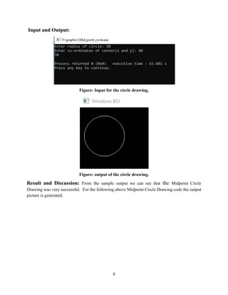
- 9. 9 Input and Output: Figure: Input for the circle drawing. Figure: output of the circle drawing. Result and Discussion: From the sample output we can see that the Midpoint Circle Drawing was very successful. For the following above Midpoint Circle Drawing code the output picture is generated.
- 10. 10 04. Name of the Problem: Program for the generation of Midpoint Ellipse Drawing. Objective: To generate basic ellipse according to Midpoint Ellipse Drawing Algorithm. Algorithm: 1. Input rx, ry, and ellipse center (xc , yc ), and obtain the first point on an ellipse centered on the origin as (x0, y0) = (0, ry) 2. Calculate the initial value of the decision parameter in region 1 as p10 = r 2 y− r 2 xry + 1 /4 r2 x 3. At each xk position in region 1, starting at k = 0, perform the following test: If p1k <0, the next point along the ellipse centered on (0, 0) is (xk+1, yk ) and p1k+1 = p1k + 2r 2 y xk+1 + r 2 y .Otherwise, the next point along the ellipse is (xk + 1, yk − 1) andp1k+1 = p1k + 2r 2 yxk+1 − 2r 2 x yk+1 + r 2 y with2r 2 yxk+1 = 2r 2 yxk + 2r 2 y, 2r 2 x yk+1 = 2r 2 x yk − 2r 2 x and continue until 2r 2 yx ≥ 2r x y. 4. Calculate the initial value of the decision parameter in region 2 as p20 = r 2 Y(x0 + ½)2 + r 2 x (y0 − 1)2 − r 2 xr 2 y where (x0, y0) is the last position calculated in region 1. 5. At each yk position in region 2, starting at k = 0, perform the following test: If p2k >0, the next point along the ellipse centered on (0, 0) is (xk , yk − 1) and p2k+1 = p2k − 2r 2 x yk+1 + r 2 x .Otherwise, the next point along the ellipse is (xk + 1, yk − 1) and p2k+1 = p2k + 2r 2 yxk+1 − 2r 2 x yk+1 + r 2 x using the same incremental calculations for x and y as in region 1. Continue until y = 0. 6. For both regions, determine symmetry points in the other three quadrants. 7. Move each calculated pixel position (x, y) onto the elliptical path centered on (xc , yc ) and plot these coordinate values: x = x + xc , y = y + yc. Source Program: #include<graphics.h> #include<stdlib.h> #include<iostream> using namespace std; int main() { int gd = DETECT, gm; int xc,yc,x,y;float p; long rx,ry; initgraph(&gd, &gm, "C:TCBGI");
- 11. 11 cout<<"Enter coordinates of centre : "; cin>>xc>>yc; cout<<"Enter x,y radius of ellipse: "; cin>>rx>>ry; p=ry*ry-rx*rx*ry+rx*rx/4; x=0;y=ry; while(2.0*ry*ry*x <= 2.0*rx*rx*y) { if(p < 0) { x++; p = p+2*ry*ry*x+ry*ry; } else { x++;y--; p = p+2*ry*ry*x-2*rx*rx*y-ry*ry;} putpixel(xc+x,yc+y,WHITE); putpixel(xc+x,yc-y,WHITE); putpixel(xc-x,yc+y,WHITE); putpixel(xc-x,yc-y,WHITE); } p=ry*ry*(x+0.5)*(x+0.5)+rx*rx*(y-1)*(y-1)-rx*rx*ry*ry; while(y > 0) { if(p <= 0) { x++;y--; p = p+2*ry*ry*x-2*rx*rx*y+rx*rx; } else { y--; p = p-2*rx*rx*y+rx*rx; } putpixel(xc+x,yc+y,WHITE); putpixel(xc+x,yc-y,WHITE); putpixel(xc-x,yc+y,WHITE);
- 12. 12 putpixel(xc-x,yc-y,WHITE); } delay(50000); closegraph(); return 0; } Input and Output: Figure: Input for the ellipse drawing. Figure: output of the ellipse drawing. Result and Discussion: From the sample output we can see that the Midpoint Ellipse Drawing is very successful. For the following above Midpoint Ellipse Drawing code the output picture is generated.
- 13. 13 05. Name of the Problem: Program for the generation of Translating an object. Objective: To reposition an object it along a straight-line path from on coordinate location to another coordinate according to Translation Algorithm. Algorithm: 1) Start 2) Initialize the graphics mode. 3) Construct a 2D object (use Drawpoly()) e.g. (x,y) 4) Get the translation value tx, ty 5) Move the 2d object with tx, ty (x’=x+tx,y’=y+ty) 6) Plot (x’,y’) Source Program: #include<bits/stdc++.h> #include<graphics.h> using namespace std; void translateLine ( int P[][2], int T[]) { initwindow(600,800); int gd = DETECT, gm, errorcode; initgraph (&gd, &gm, "c:tcbgi"); ine(getmaxx()/2,0,getmaxx()/2,getmaxy()); line(0,getmaxy()/2,getmaxx(),getmaxy()/2); line(P[0][0], P[0][1], P[1][0], P[1][1]); P[0][0] = P[0][0] + T[0]; P[0][1] = P[0][1] + T[1]; P[1][0] = P[1][0] + T[0]; P[1][1] = P[1][1] + T[1]; setcolor(3); line(P[0][0], P[0][1], P[1][0], P[1][1]);
- 14. 14 closegraph(); } int main() { int P[2][2] = {60, 70, 30, 50}; // coordinates of point int T[] = {10, 20}; // translation factor translateLine (P, T); delay(50000); closegraph(); return 0; } Input and Output: Coordinates of point: 60, 70, 30, 50 Translation factor: 10, 20 Figure: output of the ellipse drawing. Result and Discussion: From the sample output we can see that the translating an object is very successful. For the following above translation code the output picture is generated.
- 15. 15 06. Name of the Problem: Program for the generation of Rotating an Object. Objective: To reposition an object it along a circular path in the xy plane according to Rotation Algorithm. Algorithm: 1. Start 2. Initialize the graphics mode. 3. Construct a 2D object (use Drawpoly()) e.g. (x,y) 4. Get the Rotation angle 5.Rotate the object by the angle ф x’=x cos ф - y sin ф y’=x sin ф - y cosф 6. Plot (x’,y’) Source Program: #include<graphics.h> #include<stdlib.h> #include<stdio.h> #include<math.h> int main() { int graphdriver=DETECT,graphmode,errorcode; int i; int x2,y2,x1,y1,x,y,xn,yn; double r11,r12,r21,r22,th; printf("Enter the 2 line end points:"); printf("x1,y1,x2,y2:"); scanf("%d%d%d%d",&x1,&y1,&x2,&y2); initgraph(&graphdriver,&graphmode,"c:tcbgi");
- 16. 16 line(x1,y1,x2,y2); printf("nEnter the angle:"); scanf("%lf",&th); r11=cos((th*3.1428)/180); r12=sin((th*3.1428)/180); r21=(-sin((th*3.1428)/180)); r22=cos((th*3.1428)/180); xn=((x2*r11)-(y2*r12)); yn=((x2*r12)+(y2*r11)); line(x1,y1,xn,yn); getch(); closegraph(); } Input and Output: Figure: Input for the rotation of an Object.
- 17. 17 Figure: output of the rotation of an Object Result and Discussion: From the sample output we can see that the rotation of an Object is very successful. For the following above Rotation of an object code the output picture is generated.
- 18. 18 07. Name of the Problem: Program for the generation of scaling an object. Objective: To alter the size of an object by multiplying the coordinate values(x, y) according to Scaling Algorithm. Algorithm: 1. Start 2. Initialize the graphics mode. 3. Construct a 2D object (use Drawpoly()) e.g. (x,y) 4. Get the scaling value Sx,Sy 5. Resize the object with Sx,Sy (x’=x*Sx,y’=y*Sy) 6. Plot (x’,y’) Source Program: #include<stdio.h> #include<graphics.h> void findNewCoordinate(int s[][2], int p[][1]) { int temp[2][1] = { 0 }; for (int i = 0; i < 2; i++) for (int j = 0; j < 1; j++) for (int k = 0; k < 2; k++) temp[i][j] += (s[i][k] * p[k][j]); p[0][0] = temp[0][0]; p[1][0] = temp[1][0]; } void scale(int x[], int y[], int sx, int sy) { line(x[0], y[0], x[1], y[1]); line(x[1], y[1], x[2], y[2]); line(x[2], y[2], x[0], y[0]);
- 19. 19 int s[2][2] = { sx, 0, 0, sy }; int p[2][1]; for (int i = 0; i < 3; i++) { p[0][0] = x[i]; p[1][0] = y[i]; findNewCoordinate(s, p); x[i] = p[0][0]; y[i] = p[1][0]; } line(x[0], y[0], x[1], y[1]); line(x[1], y[1], x[2], y[2]); line(x[2], y[2], x[0], y[0]); } int main() { int x[] = { 50, 100, 150 }; int y[] = { 100, 50, 100 }; int sx = 2, sy = 2; int gd, gm; detectgraph(&gd, &gm); initgraph(&gd, &gm," "); scale(x, y, sx,sy); getch(); return 0; }
- 20. 20 Input and Output: Drawing X axis: line (0,240,640,240) Drawing Y axis: line (320, 0,320,480) Original object: 500, 20 Transformed object: 500, 50 Figure: output of the scaling of an object. Result and Discussion: From the sample output we can see that the scaling of an object is very successful. For the following above the scaling of an object code the output picture is generated.