


![Since the fluctuation of speed is±1%
of the mean speed (ω),
therefore total fluctuation of speed,
ω1-ω2= 2% ω = 0.02ω
& coefficient of fluctuation of speed,
Cs =[(ω1-ω2)/ω] = 0.02
maximum fluctuation of energy, ∆E,
∆E, = 2581 = I.ω2.Cs = I (62.84)2 0.02 = 79xI
:. I = 2581/79 = 32.7 kgm2…..Ans
Example-3](https://image.slidesharecdn.com/designofflywheelnew-231007052024-613e4117/85/DEsign-of-Flywheel-new-ppt-65-320.jpg)


![We know that, Mass of the flywheel rim,
m =Vol. x density=2πR x A x ρ
i.e., m=(b x t )x πD x ρ & [b=4t (given)]
Further, Energy of the flywheel rim,
Erim= (1/2)Iω2 = (1/2)mk2ω2 = (1/2)mR2ω2 (v=ωR)
= (1/2)xmxv2 [Erim=(15/16)E …given]
And Max. fluctuation of energy, ∆E= E x 2 Cs
& hoop Stress=σt=ρv2 & v=πDN/60
Example-4](https://image.slidesharecdn.com/designofflywheelnew-231007052024-613e4117/85/DEsign-of-Flywheel-new-ppt-73-320.jpg)
![Tmean transmitted by the engine or flywheel.
Power transmitted, P= (2xπxNxTmean)/60
i.e., 50x103= (2xπx150xTmean)/60 =15.71 Tmean
Tmean= 50 x 103/15.71= 3182.7 N-m
Workdone/cycle = Tmeanx θ = 3182.7 x 4 π= 40000 Nm
{Or The workdone per cycle for a 4 stroke engine,
Workdone l cycle =[(Px60)/(No. of explosions/min)]
=(Px60)/n = (50000x60)/75=40000 Nm}
:. Workdone during power stroke =1.4xWorkdone/cycle
=1.4x40000 = 56000 N-m
Example-4](https://image.slidesharecdn.com/designofflywheelnew-231007052024-613e4117/85/DEsign-of-Flywheel-new-ppt-74-320.jpg)


DEsign of Flywheel new.ppt
- 1. Flywheel
- 2. • Necessity In a combustion engine, & especially in one with one or two cylinders, energy is imparted to the crankshaft intermittently, & in order to keep it rotating at a fairly uniform speed under a substantially constant load, it is necessary to provide it with a flywheel. Flywheel
- 3. • In a single cylinder engine(4 Stroke), in which there is only one power stroke in two revolutions of the crankshaft, a considerable fraction of energy generated per cycle is stored in the flywheel, & the proportion thus stored decreases with an increase in the No. of cylinders • In a 4 cylinder engine about 40% of the energy of the cycle is temporarily stored. Flywheel
- 4. However, not all of this energy goes into flywheel During the 1st half of the power stroke, when energy is being supplied in excess by the burning gases, all of the reciprocating parts of the engine are being accelerated & absorb energy; besides, the rotating parts other than the flywheel also have some flywheel capacity, & this reduces the proportion of the energy of the cycle which must be stored in the flywheel. Flywheel
- 5. • In a 6 cylinder engine the proportion of the energy which must be absorbed & returned by the moving parts amounts to about 20%. • The greater the No. of cylinders the smaller the flywheel capacity required per unit of piston displacement, because the overlap of power strokes is greater & besides other rotating parts of the engine have greater inertia. Flywheel
- 6. • However, the flywheel has by far the greatest inertia even in a multi cylinder engine. • Aside from its principle function, the fly wheel serves as a member of the friction clutch, & it usually carries also the ring gear of the electric starter. Flywheel
- 7. Flywheel
- 8. Flywheel
- 9. Flywheel •Energy accumulator •Energy re-distributor •A flywheel serves as a reservoir which stores energy during the period when the supply of energy is more than the requirement & releases, it during the period when the requirement of energy is more than supply. •A flywheel helps to keep the crankshaft rotating at a uniform speed
- 10. In internal combustion engines, • the energy is developed during one stroke and the engine is to run for the whole cycle on the energy produced during this one stroke. • the energy is developed, only during power stroke which is much more than the engine load; and no energy is being developed during suction, compression and exhaust strokes in case of 4 stroke engines & during compression in case of 2 stroke engines. Flywheel
- 11. • The excess energy developed during power stroke is absorbed by the flywheel and releases it to the crankshaft during other strokes in which no energy is developed, thus rotating the crankshaft at a uniform speed. • When the flywheel absorbs energy, its speed increases and when it releases, the speed decreases. Hence a flywheel does not maintain a constant speed, it simply reduces the fluctuation of speed. Flywheel
- 12. • The function of a governor in engine is entirely different from that of a flywheel Governor regulates the mean speed of an engine when there are variations in the load, e.g., when the load on the engine increases it becomes necessary to increase the supply of Working fluid. On the other hand, when the load decreases, less working fluid is required. The governor automatically; controls the supply, of working fluid to the engine with the varying load condition and keeps the mean speed within certain limits. Flywheel
- 13. • The flywheel does not maintain constant speed • It simply reduces the fluctuation of speed. • A flywheel controls the speed variations caused by the fluctuation of the engine turning moment during each cycle of operation. It does not control the speed variations caused by the varying load. Flywheel
- 14. Capacity & Diameter • The flywheel capacity of a given mass increases with its distance from the axis of rotation ; consequently, if the flywheel is made large in diameter it need not be so heavy. • On the other hand there are two reasons for limiting the diameter. – At high rpm, flywheel is subjected to disruptive or bursting force, & by keeping down the diameter, the F O S can be kept high. – As it is cast or cast & pressed steel housing, this need not weigh so much if the diameter is smaller Flywheel
- 15. Flywheel A Flywheel is given a high rotational inertia; i.e., most of its weight is well out from the axis
- 17. Construction of Flywheels The flywheels of smaller size (up to 600 mm diameter) are casted in one piece. The rim & hub are joined together by means of web. The holes in the web may be made for handling purposes.
- 18. In case the flywheel is of larger size (up to 2.5m diameter), the arms are made instead of web. The number of arms depends upon the size of flywheel & its speed of rotation. Construction of Flywheels
- 19. The split flywheels are above 2.5m diameter & are usually casted in two piece. It has advantage of relieving shrinkage stresses in arms due to unequal rate of cooling of casting. Construction of Flywheels
- 20. Maximum Fluctuation of Speed & Coefficient of Fluctuation of Speed
- 21. •The Maximum Fluctuation of Speed the difference between the maximum & minimum speeds during a cycle. i.e., =(N1-N2) Where, N1=Maximum speed in r.p.m. during the cycle, N2=Minimum speed in r.p.m. during the cycle •The Coefficient of Fluctuation of Speed is the ratio of the maximum fluctuation of speed to the mean speed. Flywheel
- 22. 1/Cs m Steadiness of t Coefficien flywheel. of design the in factor limiting a is C The .... v v v v 2 v v v ..... ω ω ω ω 2 ω ω ω N N N N 2 N N N C C Speed of n Fluctuatio t Coefficien N N m p r in Speed Mean N s 2 1 2 1 2 1 2 1 2 1 2 1 2 1 2 1 2 1 s s 2 1 speeds linear of terms in speeds angular of terms in 2 / Flywheel
- 23. Fluctuation of Energy The Fluctuation of Energy may be determined by the turning moment diagram for one complete cycle of operation
- 24. • turning moment is zero when the crank angle is zero • It rises to a max. value when crank angle reaches 90° and it is again zero when crank angle is 180°. Flywheel
- 25. • work done=turning moment x angle turned • The area of the turning moment diagram represents the work done per revolution • Engine is assumed to work against the mean resisting torque, • Since it is assumed that work done by the turning moment / revolution = work done against the mean resisting torque Therefore, area of rectangle (aAFe) is proportional to work done against the mean resisting torque. Flywheel
- 26. • When crank moves from 'a' to 'p' work done by the engine is = area aBp, whereas the energy required = area aABp. • In other words, the engine has done less work than the requirement. This amount of energy is taken from the flywheel and hence the speed of the flywheel decreases. Flywheel
- 27. Now the • crank moves from p to q, • work done by the engine = area pBbCq • requirement of energy = area pBCq • Therefore the engine has done more work than the requirement. This excess work is stored in the flywheel and hence the speed of the flywheel increases while the crank moves from p to q. Flywheel
- 28. • Similarly when the crank moves from q to r, more work is taken from engine than is developed= area CcD. To supply this loss, the flywheel gives up some of its energy and thus the speed decreases while the crank moves from q to r. • As the crank moves from r to s, excess energy is again developed = area DdE & the speed again increases. • As the piston moves from s to e, again there is a loss of work & the speed decreases. Flywheel
- 29. •The variations of energy above and below the mean resisting torque line are called fluctuation of energy. The areas BbC, CcD, DdE etc. represent fluctuations of energy. Flywheel
- 30. • Engine has a max. speed either at q or at s. This is due to the fact that flywheel absorbs energy while the crank moves from p to q and from r to s. • Engine has a minimum speed either at p or at r. The reason is that flywheel gives out some of its energy when the crank moves from a to p and q to r. • The difference between the maximum and the minimum energies is known as maximum fluctuation of energy. Flywheel Mean Speed Maximum Speed Speed Crankangle Min. Speed
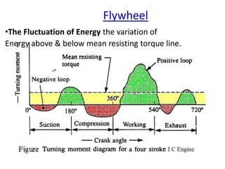
- 31. Flywheel •The Fluctuation of Energy the variation of Energy above & below mean resisting torque line.
- 32. For a 4 Stroke IC Engine, •During suction stroke, since the pr. inside the engine cylinder is less than the atmospheric pr., a negative loop is formed •During compression stroke, the work is done on the gases, there a higher negative loop is obtained •In the working stroke, the fuel burns & the gases expand, therefore a large positive loop is formed •During exhaust stroke, the work is done on the gases, therefore a negative loop is obtained Flywheel
- 33. Maximum Fluctuation of Energy
- 35. 4 3 2 1 1 a a a a E a E ΔE Energy, of n Fluctuatio Maximum ly. respective E & B at is Energies these of Min. & Max. the Let A at Energy a a a a a a E G at Energy a a a a a E F at Energy a a a a E E at Energy a a a E D at Energy a a E C at Energy a E B at Energy fig., from then E, A at flywheel in Energy Let 6 5 4 3 2 1 5 4 3 2 1 4 3 2 1 3 2 1 2 1 1
- 36. Coefficient of Fluctuation of Energy
- 37. ly respective Engines C I st. & for n strokes/mi working of No. n 60 P θ rad/sec in ω watts in P θ N 2π 60 P cycle per done Work or rad/sec in ω watts in P N 2π 60 P m - N in torque Mean T & ly respective Engines C I st. & for & rad/sec in turned Angle θ where, E 4 2 N/2 & N n 4 2 4π 2π T cycle per done Work Energy Min. - Energy Max. cycle per done Work Energy of n Fluctuatio Max. C rpm in rpm in mean mean E ) (C energy of n fluctuatio of t Coefficien n E E P 60
- 38. Energy stored in a flywheel
- 39. 2 2 1 2 1 2 1 2 1 mk I & )/ω/ ω (ω )/N N (N s )/2 ω (ω mean )/2, N (N mean C ω N where, or s 2 2 C ω I ω ω ω Iω ω I 2 1 ω I 2 1 K.E Min. - K.E Max. ΔE ΔE Energy, of n fluctuatio Max. , ω to ω from changes speed As J or Nm ω mk 2 1 Iω 2 1 E E Flywheel of Energy Kinetic Mean s C 2E ΔE C ω mk s 2 2 1 2 2 2 2 1 2 1 2 2 2 Flywheel a in Stored Energy
- 40. out found be can t & b , 2 usuallyb/t ratio b/t Knowing t, b A then r, rectangula be to rim of area c/s Assuming density vol. m rim flywheel of Mass determined be may flywheel of mass this From C mv C ω mR ΔE R Rim of radius mean k gyration of Radius s 2 s 2 2 diameter, to compared small very is rim of thickness As of rim thickness width & t where,b rim. of area c/s find may we this From neglected hub & arms & that of considered of rim is nertia oment of i nly mass m ression, o ve in the abo ρ A πR R v 2 , exp ,
- 41. Example-1
- 42. Example-1 The turning moment diagram for a Petrol engine is drawn to following scales: Turning moment, 1 mm =5 Nm; Crank angle, I mm = 1°; The turning moment diagram repeats itself at every half revolution of the engine and the areas above and below mean turning moment line, taken in order are 295, 685, 40, 340, 960, 270 mm2. Determine the mass of 300 mm diameter flywheel rim when the coefficient of fluctuation of speed is 0.3% and the engine runs at 1800 r.p.m.. Also determine the cross-section of the rim when the width of the rim is twice of thickness. Assume density of rim material as 7250 kg/m3.
- 43. Example-1… •Solution; Given: ρ = 7250 kg/m3; Cs = 0.3% = 0.003; D = 300 mm or R = 150 mm = 0.15 m; N =1800r.p.m. or ω = 2 π x 1800 /60 = 188.5rad/s m, b, t = ? ∆ E = Iω2Cs = m.R2.ω2Cs m = ρV = ρ.(πD.A) = ρ.(2πR.A) A = b x t, b=2t
- 44. •Mass of the flywheel (m kg) As per given scale, on the turning moment diagram, 1 mm2 = 5 Nm x 10 = 5 x(10 xπ /180) = 0.087 Nm Max. fluctuation of energy = ∆ E = m.R2.ω2Cs Let the total energy at A = E, from fig., Energy at B = E + 295 Energy at C = E + 295 - 685 = E - 390 Energy at D = E - 390 + 40 = E - 350 Energy at E = E - 350 - 340 = E - 690 Energy at F = E - 690 + 960 = E + 270 Energy at G = E + 270 - 270 =E=Energy at A Example-1…
- 45. :. Maximum energy =E+295 at B& Minimum energy =E-690 at E Maximum fluctuation of energy, i.e. ∆ E =Max. energy – Min. energy =(E + 295) - (E - 690) = 985 mm2 =985 x 0.087=86 Nm Also, Maximum fluctuation of energy, i.e. ∆ E = 86 =m.R2.ω2Cs =m (0.15)2 (188.5)2 (0.003) = 2.4xm :. m = 86/2.4 = 35.8 kg………Ans. Example-1…
- 46. Example-1… •Cross-section of the flywheel rim Mass of the flywheel rim, m =Vol. x density =(A x 2πR) xρ Let, Width of rim, b=2 x t, thickness of rim :. Cross-sectional area of rim, A=b x t = 2t x t = 2 t2 mass of the flywheel rim (m) = 35.8 = A x 2πRx ρ =2 t2 X2 π x 0.15 x 7250 =13668 t2 :. t2 =35.8/13668 =0.0026 or t =0.051 m = 51mm….Ans. & b =2 t =2 x 51 = 102 mm….Ans.
- 47. Example-2
- 48. Example-2 A single cylinder, single acting,4 stroke oil engine develops 20 kW at 300 r.p.m. The work done by the gases during expan. stroke is 2.3 times the work done on the gases during the compression and work done during the suction and exhaust strokes is negligible. The speed is to be maintained within ±1%. Determine the mass moment of inertia of the flywheel.
- 49. Solution; Given: P = 20kW =20x 103 W; N = 300r.p.m. or ω= 2πx300/60 =31.42rad/s Cs=±1% or ω1- ω2= ±1%ω Example-2 ∆ E = Iω2Cs
- 50. Example-2… Nm / /n P ycle done per c also, work 8000 150 60 10 20 60 3 Nm 8000 π 4 X 636.5 θ X T ycle workdone/c Nm 636.5 300 2π x60 10 20x N 2 Px60 T engine, by d transmitte torque Mean xCs Ix E energy, of n fluctuatio Maximum • mean 3 mean 2 I inertia, of moment Mass
- 51. Example-2… 14160Nm 8000/0.565 W 0.565W /2.3 W W 8000Nm or W W cycle per workdone done work Net stroke expn. during done work W & stroke comprn. during done work W let, E E E E C E E C
- 52. The work done during expan. stroke is shown by triangle ABC in Fig., in which base AC =π radians & height BF =Tmax :. Work done during expansion stroke, WE =14160 =(1/2) X π X Tmax = 1.571 Tmax Or Tmax= 14160/1.571 = 9013 Nm Height above the mean torque line, BG = BF - FG = Tmax- Tmean = 9013 - 636.5 = 8376.5 Nm Example-2…
- 53. Example-2… N-m . x . x / x DE x BG / BDE) le a ofΔ (i.e., are :. Δ. rad . π . π T ) mean -T (T AC BF BG DE or BF BG AC DE and BAC, ngles BDE milar tria s, From si as follow calculated ΔE may be also, 12230 5 8376 92 2 2 1 2 1 92 2 9013 5 8376 max max Nm 12230 9013 8376.5 14160 T ) T - (T W E Δ BF (BG) W BF (BG) ABC Δ of Area E i.e.Δ BDE), Δ of Area (i.e. energy of n fluctuatio Max. , BF (BG) ABC Δ of Area BDE Δ of Area relation, l geometrica from 2 2 2 max 2 mean max E 2 2 E 2 2 le le 2 2 le le
- 54. Example-2… .Ans .......... 619.5kgm 4 12230/19.7 I 2 I 19.74 0.02 (31.42) I C Iω 12230 i.e. C Iω ΔE E energy, of n fluctuatio maximum that know We . kgm in flywheel the of inertia of moment Mass I Let 0.02 ω ω - ω C speed, of n fluctuatio of t coefficien and ω 0.02 ω % 2 ω - ω speed of n fluctuatio total therefore speed, mean the of 1% within maintained be to is speed the Since 2 s 2 s 2 2 2 1 s 2 1
- 55. Stresses in a Flywheel Rim
- 56. Stresses in a Flywheel Rim •A flywheel, consists of a rim at which major portion of mass or weight is concentrated. •Following types of stresses are induced in the rim 1. Tensile stress due to centrifugal force, 2. Tensile bending stress caused by the restraint of the arms, and 3. The shrinkage stresses due to unequal rate of cooling of casting. This stress is taken care of by a factor of safety. b = Width of rim, t =Thickness of rim, A = Cross-sectional area of rim = b x t. D = Mean diameter of flywheel R =Mean radius of flywheel, ρ =Density of flywheel material, ω =Angular speed of flywheel, V =Linear velocity of flywheel, and σt =Tensile/hoop stress
- 57. Stresses in Rim 1. Tensile stress due to centrifugal force The tensile stress in the rim due to the centrifugal force, assuming that rim is unstrained by arms, is determined in a similar way as a thin cylinder subjected to internal pr.. Tensile stress, σt =ρ.R2.ω2 =ρ.v2 ...(v = ω.R) (when ρ is in kg/m3 and v is in m/s, then σt will be in N/m2 or Pa) Note: From the above expression the mean diameter (D) of the flywheel may be obtained by using the relation v=πDN / 60
- 58. t n R ρv . b σ v /R) ing (Substitut t n R ρω . bt n πR R btρ bt wl Z M σb 2 2 74 19 6 2 12 6 12 74 19 2 3 2 2 2 2 2 2 b σ stress, Bending loaded, uniformly and ends both at fixed beam a like behaves arms of pair a betn. rim of portion each that assumption the on based is arms of restraint the to due rim the in stress bending tensile The arms the of restraint by caused stress bending Tensile 2. Stresses in Rim
- 60. Example-3
- 61. Example-3 A multi-cylinder engine is to run at a constant load at a speed of 600 r.p.m. On drawing the crank effort diagram to scale of 1 m = 250 Nm and 1 mm = 3°, The areas in mm2 above & below mean torque line are: + 160,- 172, + 168,- 191, + 197,- 162 mm2 The speed is to be kept within ±1% of the mean speed of the engine. Calculate the necessary moment of inertia of the flywheel. Determine suitable dimensions for cast iron flywheel with a rim whose breadth is twice its radial thickness. The density of cast iron is 7250 kg/m3, and its working stress in tension is 6MPa. Assume that rim contributes 92% of flywheel effect.
- 62. Example-3 •Solution. Given: N =600 r.p.m. or ω =2π x 600/60 =62.84 rad/s; ρ =7250 kg/m3; σt =6 MPa =6 x 10⁶ N/m2 ∆ E = Iω2Cs σt=ρ.v2 v = (πDN)/60 ∆ E = m.R2.ω2Cs m = ρV = ρ.(πD.A)= ρ.(2πR.A) A = b x t, b=2t
- 63. •Moment of inertia of the flywheel We know that, Maximum fluctuation of energy, ∆E= Ixω2xCs Scale for the turning moment is 1 mm = 250 Nm & scale for the crank angle is 1 mm = 3°= 3°xπ/180= π/60 rad, therefore 1 mm2 on the turning moment diagram i.e., 1 mm2 =250 x π/60 = 13.1 Nm Example-3
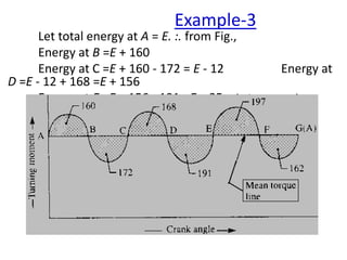
- 64. Let total energy at A = E. :. from Fig., Energy at B =E + 160 Energy at C =E + 160 - 172 = E - 12 Energy at D =E - 12 + 168 =E + 156 Energy at E =E + 156 - 191 =E – 35 (min. energy) Energy at F = E - 35 + 197 =E + 162 (max. energy) Energy at G =E + 162 - 162 = E =Energy at A Max. fluctuation of energy, ∆ E =Max. energy – Min. energy = (E + 162) - (E - 35) = 197 mm2 ∆ E =197 x 13.1=2581 N-m Example-3
- 65. Since the fluctuation of speed is±1% of the mean speed (ω), therefore total fluctuation of speed, ω1-ω2= 2% ω = 0.02ω & coefficient of fluctuation of speed, Cs =[(ω1-ω2)/ω] = 0.02 maximum fluctuation of energy, ∆E, ∆E, = 2581 = I.ω2.Cs = I (62.84)2 0.02 = 79xI :. I = 2581/79 = 32.7 kgm2…..Ans Example-3
- 66. •Dimensions of a flywheel rim We know that, Mass of the flywheel rim, m = Vol. x density =2πR x A x ρ = πD x (b x t )x ρ b=2t (given) •Peripheral velocity (v) & mean diameter (D) We know that, tensile stress, σt=ρ.v2 i.e., σt=6 x 106=ρ.v2 =7250 X v2 So, v2 =(6 x 10⁶)/7250 =827.6 or v =28.76 m/s We also know that, peripheral velocity,v = (πDN)/60 i.e., v=28.76 = (πDN)/60 = (πDx600)/60 = 31.42 D So D = 28.76/31.42 = 0.915 m = 915 mm …Ans. Example-3
- 67. •Mass of flywheel rim Since rim contributes 92% of flywheel effect, :. Energy of flywheel rim, Erim = 0.92 x total Energy of the flywheel, E Max. fluctuation of energy, ∆E= E x 2 Cs i.e., ∆E =2581 = E x 2 Cs =E x 2 x 0.02 = 0.04 E :. E = 2581/ 0.04 = 64525 N-m & Energy of flywheel rim, Erim = 0.92 E (v=ωR) = 0.92 x 64525 = 59363 Nm Also, Erim= (1/2)Iω2 = (1/2)mk2ω2 = (1/2)mR2ω2 = (1/2)xmxv2 i.e., 59363 = 1/2 x m x v2 = 1/2 x m (28.76)2 = 413.6 m :. m = 59363/413.6 = 143.5 kg Example-3
- 68. The mass of the flywheel rim may also be obtained by using following relations. Since the rim contributes 92% of the flywheel effect, •Irim = 0.92xIflywheel or m.k2= 0.92 x 32.7 =30 kgm2 Since radius of gyration, k =R =D/2 = 0.915/2 =0.4575m, i.e., m=(30/k2) =(30/0.45752) =(30/0.2092)=143.5kg •(∆ E) rim = 0.92 (∆ E )flywheel m. V2.CS = 0.92 (∆ E )flywheel m (28.76)2x0.02= 0.92x 2581 16,55xm = 2374.5 or m = 2374.5/16.55= 143.5kg Example-3
- 69. m = 59363/413.6 = 143.5 kg Also,mass of the flywheel rim, m= (b x t )x πD x ρ & b=2t (given) 143.5 = b x t x πD x ρ =2 t X t X π x 0.915 x 7250 = 41686 t2 t2 = 143.5/41686 =0.00344 t =0.0587 say 0.06 m =60 mm Ans. b =2 t =2 x 60 = 120 mm Ans. Example-3
- 70. Example-4
- 71. Example-4 An otto cycle engine develops 50 kW at 150 r.p.m. with 75 explosions per minute. The change of speed from the commencement to the end of power stroke must not exceed 0.5% of mean on either side. Design a suitable rim section having width four times the depth so that the hoop stress does not exceed 4 MPa. Assume that the flywheel stores 16/15 times the energy stored by the rim and that the workdone during power stroke is 1.40 times the workdone during the cycle. Density of rim material is 7200 kg/m3
- 72. •Solution. Given: P =50 kW =50 X 103W; N = 150r.p.m.; n =75 ; σt =4 MPa =4 x 10⁶ N/m2; ρ =7200 kg/m3 Example-4
- 73. We know that, Mass of the flywheel rim, m =Vol. x density=2πR x A x ρ i.e., m=(b x t )x πD x ρ & [b=4t (given)] Further, Energy of the flywheel rim, Erim= (1/2)Iω2 = (1/2)mk2ω2 = (1/2)mR2ω2 (v=ωR) = (1/2)xmxv2 [Erim=(15/16)E …given] And Max. fluctuation of energy, ∆E= E x 2 Cs & hoop Stress=σt=ρv2 & v=πDN/60 Example-4
- 74. Tmean transmitted by the engine or flywheel. Power transmitted, P= (2xπxNxTmean)/60 i.e., 50x103= (2xπx150xTmean)/60 =15.71 Tmean Tmean= 50 x 103/15.71= 3182.7 N-m Workdone/cycle = Tmeanx θ = 3182.7 x 4 π= 40000 Nm {Or The workdone per cycle for a 4 stroke engine, Workdone l cycle =[(Px60)/(No. of explosions/min)] =(Px60)/n = (50000x60)/75=40000 Nm} :. Workdone during power stroke =1.4xWorkdone/cycle =1.4x40000 = 56000 N-m Example-4
- 75. The workdone during power stroke is shown by ∆le ABC in Fig in which base AC =π radians and height BF = Tmax :. Workdone during working stroke= 1/2xπXTmax = 1.571 Tmax :. Also Workdone during working stroke=56000 Nm :. Tmax=(56000/1.571) =35646Nm Height above the mean torque line, BG = BF-FG = Tmax-Tmean = 35646-3182.7= 32463.3Nm Example-4
- 77. Mean diameter of the flywheel (D) Hoop stress, σt=ρv2 i.e., 4 x 106= ρ.v2 = 7200 X v2 :. v2 =4 X 10⁶/7200 = 556 or v = 23.58 m/s Peripheral velocity, v = πDN/60 i.e., 23.58 = πDN/60 = πDx150/60 =7.855 D D =23.58/7.855 D=3 m …Ans. Example-4
- 78. Cross-sectional dimensions of the rim Cross-sectional area of the rim, A=b x t= 4t x t =4t2 (b=4t..given) Since N1 - N2 = 0.5% N either side, (..given) :. total fluctuation of speed, N1 - N2 = 1% of mean speed =0.01 N & coefficient of fluctuation of speed, Cs. = (N1 - N2)/N = 0.01 E = Total energy of the flywheel. Maximum fluctuation of energy (∆ E), 46480 = Ex 2 Cs = E x 2 x 0.01 = 0.02 E :. E = 46480/0.02 =2324 x 103 Nm Example-4
- 79. Since the energy stored by the flywheel is 16/15 times the energy stored by rim, Therefore the energy of the rim, Erim = (16/15)E= (16/15)x 2324 x 103 = 2178.8 x 103Nm Also Erim= (1/2)xmxv2 i.e., 2178.8 X 103 = (1/2)xmx(23.58)2 =278xm :. m = 2178.8 x103 / 278 =7837 kg Also, mass of the flywheel rim, m= A x πD x ρ i.e., 7837 = A x πD x ρ =4 t 2 X π X 3 x 7200 =271469 t2 or t2 = 7837 / 271469 = 0.0288 or t = 0.17 m = 170 mm …Ans. b =4 t =4 x 170 = 680 mm …Ans. Example-4
- 80. Example-5
- 82. Example-5… 3 2 s mean max s 2 7200kg/m iron cast of Density 39.23N/mm f stress shear Safe T T cycle whole the during done work ave. 3 1 1 stroke power during done Work 0.04 K speed of n Fluctuatio 3.92N/mm material in stress Hoop 800rpm @ 36.8kw Power Flywheel iron Cast Given, : Solution ∆ E = Iω2Cs σt=ρ.v2 v = (πDN)/60 ∆ E = m.R2.ω2Cs m = ρV = ρ.(πD.A)= ρ.(2πR.A) A = b x t, b=2t
- 83. Example-5…
- 85. Example-5…
- 88. Example-5… 0.0761m t t 4t 0.546 π 0.0397 4t b let, , t b πD Area R 2 V Also, 0.0397m 9.81 7200 2803 g ρ 2803 w , W , V further, 2803N W Weight, 2 0.546 9.81 W 2 D g W 21.3 I wheel} rimmed thin for R rim, of radius mean {k mk gyration of radius flywheel of mass rotation of axis about inertia of momemt mass I that, know We rim 3 rim 2 2 2 2 density Weight ., .e i
- 90. Stresses in Flywheel Arms
- 91. Stresses in Flywheel Arms Following stresses are induced in the arms of a flywheel •Tensile stress due to centrifugal force acting on the rim. •Bending stress due to torque transmitted from the rim to the shaft or from the shaft to the rim. •Shrinkage stresses due to unequal rate of cooling of casting. These stresses are difficult to determine.
- 92. •Tensile stress due to centrifugal force Due to the centrifugal force acting on the rim, the arms will be subjected to direct tensile stress whose magnitude is, :. Tensile stress in the arms, σt1= (3/4)σt= (3/4)ρxv2 Stresses in Flywheel Arms
- 93. •Bending stress due to torque transmitted T =Maximum torque transmitted by the shaft, Z = Section modulus for the c/s of arms & R =Mean radius of rim r =Radius of the hub n =Number of arms Stresses in Flywheel Arms
- 95. Design of Flywheel Arms
- 96. D/n of Arms (2) & (1) equations by obtained dimensions arms , b 2 a Assuming 2 r)....... - (R Z n R T Z M σ arms, in stress ding MaximumBen r) - (R n R T M moment, bending maximum that know We 1 ....... a b x 32 π Z modulus, Section stress. bending max. for desgnedned is it & axis, minor the twice as axis major with elliptical usually is arms the of c/s The 1 1 b 2 1 1
- 97. Design of Shaft, Hub and Key
- 98. Design of Shaft, Hub and Key shaft. of material the for stress shear Allowable & shaft, the of Diameter d where, 16 T d, transmitte torque Maximum d. transmitte torque maximum the from obtained is flywheel for shaft of diameter The 1 max 3 1 d
- 101. Example-6
- 102. Design and draw a cast iron flywheel used for a four stroke I.C engine developing180 kW at 240 r.p.m. The hoop or centrifugal stress developed in the flywheel is5.2 MPa, the total fluctuation of speed is to be limited to 3% of the mean speed. The work done during the power stroke is 1/3 more than the average work done during the whole cycle. The max. torque on shaft is twice the mean torque. The density of cast iron is 7220 kg/m3. Example-6
- 103. Solution. Given: P =180kW =180X 103W; N = 240r.p.m.; σt = 5.2MPa = 5.2x 10⁶N/m2; Nl - N2 = 3% N; ρ = 7220 kg/m3 . Turning moment diagram of a 4 stroke engine is shown in Fig. Example-6
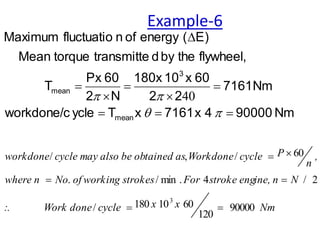
- 104. Nm x x cycle done Work :. N ine, n stroke eng For g strokes of workin No where n , n P cycle Workdone tained as also be ob cycle may workdone 90000 120 60 10 180 / 2 / 4 . min / . 60 / , / 3 40 Nm 90000 4 x 7161 x T ycle workdone/c Nm 7161 2 2 60 x 10 180x N 2 60 Px T flywheel, the by d transmitte torque Mean E) ( energy of n fluctuatio Maximum mean 3 mean Example-6
- 105. Example-6 Nm 76384 2 120000x T 120000 T X x T X x stroke power during Workdone T BF height & radians AC base which, in Fig. in ABC a by shown is stroke power the during Workdone Nm 120000 90000 x 3 1 90000 stroke working) (or power the during Workdone cycle, whole during workdone average than more times 1/3 is stroke power during workdone Since max max max max le 2 1 2 1
- 113. Example-6 ....Ans. mm 160 say 159 L ......Ans mm 20 key of thickness & s ........An mm 36 w key of Width key of Dimensions 6. 3 3 3 3 max 10 90 / 10 x 14322 L 10 90 2 125 x 40 x 36 x L d w L 10 x 14322 T , shaft the by d transmitte torque Max. . : follows as are mm 125 diameter of shaft a for key sunk r rectangula of dimensions standard The shearing in key of failure g considerin by obtd. is (L) key of Length 2 1