SlideShare a Scribd company logo
Unit-2 Electro Chemical Machining
Topics need to be covered
1. Fundamentals of ECM
2. Introduction of ECM
3. Elements of ECM
4. Working of ECM
5. MRR
6. Tool Design
7. Surface finish and accuracy
8. Economic aspects
9. Advantages and Disadvantages
10. Simple problems
11. Electro chemical honing ,Grinding and deburring process
Fundamentals of ECM
What is
oxidation and
reduction??
Anode and
cathode??
Answers
Electrolysis
 The passage of a direct electric current through an ionic
substance that is either molten or dissolved in a suitable
solvent, resulting in chemical reactions at electrodes.
 The chemical reaction is one in which the substance loses or
gains an electron.
Requirements of electrolysis
 Two electrodes
 An Electrolyte
 Power Supply (DC )
Michael faraday
electrochemical cell
An electrolyte - It is a substance
containing free ions which are the
carriers of electric current in the
electrolyte solution
 Electrode is an electrical conductor
which provides the physical interface
between the electrical circuit providing
the energy and the electrolyte
An anode is an electrode through which
conventional current flows into a polarized electrical
device.
The terms anode and cathode do not relate to
the voltage polarity of those electrodes but
the direction of the current: whether positive
charge is flowing into or out of the device.
The part of an electrical device (such as a battery)
from which electrons leave.
The electrode of an electrochemical cell at which
oxidation occurs. (The positive terminal of an
electrolytic cell)
The electrode of an electrochemical cell at which
reduction occurs. (The negative terminal of an
electrolytic cell)
The part of an electrical device (such as a battery)
where electrons enter is called as cathode.
Redox (short for reduction–oxidation reaction)
Oxidation is the loss of electrons or an
increase in oxidation state by a molecule,
atom, or ion.
Reduction is the gain of electrons or a
decrease in oxidation state by a
molecule, atom, or ion
Example, during the combustion of
wood, oxygen from the air is
reduced, gaining electrons from the
carbon.
• The process uses an apparatus consisting of positive and negative electrodes
which are separated from each other in a solution.
• Electric current enters through the positively charged electrode (anode).
• Positively charged parts of the solution travel to the cathode, combine with
the electrons, and are transformed into neutral molecules.
• The negatively charged parts of the solution travel to the positive electrode
(anode), give up electrons, and are transformed into neutral molecules.
Electrolysis Process
Electrolysis Process………
Sodium chloride (salt) is made of an alkali metal and a halogen. When it’s dissolved
we call the solution “brine”, and we can electrolyse it to produce 3 things…
Positive
electrode
Negative
electrode
Chlorine gas (Cl2) – used to kill
bacteria and to make acids, bleach
and plastics
Hydrogen gas (H2) – used to
manufacture ammonia and margarine
Sodium chloride (brine) NaCl(aq)
Sodium hydroxide (NaOH(aq)).
Used to make soap, paper and
ceramics
Ecm by g.venkatesh
 The positive anode attracts the negative hydroxide OH– ions (from water) and
chloride Cl– ions (from sodium chloride).
 The chloride ions are oxidised by electron loss to give chlorine molecules at the
positive electrode which attracts negative ions.
An oxidation electrode reaction
2Cl–
(aq) – 2e– ==> Cl2(g)
or 2Cl– ==> Cl2(g) + 2e–
Chemical reactions of ANODE
 The negative (–) cathode attracts the Na+ (from sodium chloride) and H+ ions
(from water).
 The hydrogen ions are reduced by electron (e–) gain to form hydrogen
molecules at the negative electrode which attracts positive ions.
2H+
(aq) + 2e– ==> H2(g)
other equation
2H2O(l) + 2e– ==> H2(g) + 2OH-
(aq)
Chemical reactions of CATHODE
The hydroxide ion reacts with the unchanged sodium ion, finally residual solution
contains sodium hydroxide. In fact this is how sodium hydroxide is manufactured
in the chemical industry.
Na+ + OH– = NaOH
If most of the chloride ions have been discharged as chlorine molecules, you can
then get some oxygen gas formed at the anode.
2H2O(l) – 4e– ==> 4H+
(aq) + O2(g)
or
4OH–
(aq) – 4e– ==> 2H2O(l) + O2(g) (oxygen gas)
Play Video
Electroplating is often called "electro deposition“.
Electro deposition is the process of producing a
coating, usually metallic, on a surface by the action
of electric current.
Electroplating is a surface coating method that
forms an adherent layer of one metal on
another .
To achieve the desired electrical and corrosion
resistance, reduce wear & friction, improve heat
tolerance and for decoration purposes
Electroplating of Copper
The electroplating of copper in which the
metal to be plated (copper) is used as the
anode .
The electrolyte solution contains the ion of
the metal to be plated (Cu2+ in this example).
anode: Cu(s) → Cu2+(aq) + 2 e-
cathode: Cu2+(aq) + 2 e- → Cu(s)
Procedure of Electroplating In detail
1. The article to be plated (the work) is made the cathode (negative electrode) of an
electrolysis cell through which a direct electric current is passed.
2. The anode is usually a bar of the metal being plated.
3. Both the anode and the cathode are immersed in a solution which contains a
dissolved metal salt (e.g., an ion of the metal being plated) and other ions which act
to permit the flow of electricity through the circuit.
4. During electrolysis metal is deposited on to the work and metal from the bar
dissolves:
at cathode MZ+(aq) + ze-→ M(s)
at anode M(s) → MZ+(aq) +ze-
Metal Anode Electrolyte Application
Cu Cu 20% CuSO4, 3% H2SO4 electrotype
Ag Ag 4% AgCN, 4% KCN, 4% K2CO3 jewelry, tableware
Au Au, C, Ni-Cr 3% AuCN, 19% KCN, 4% Na3PO4 buffer jewelry
Cr Pb 25% CrO3, 0.25% H2SO4 automobile parts
Ni Ni 30% NiSO4, 2% NiCl2, 1% H3BO3 Cr base plate
Zn Zn 6% Zn(CN)2, 5% NaCN, 4% NaOH, 1% Na2CO3,
0.5% Al2(SO4)3
galvanized steel
Sn Sn 8% H2SO4, 3% Sn, 10% cresol-sulfuric acid tin-plated cans
Play Video
What is ECM??
Electrochemical Machining (ECM)
Is a Method of Removing Metal
Particles by an Electro- Chemical
Process Instead of Standard
Machining Methods .
HISTORY
• The First Introduction Of ECM Was In 1929 by Gusseff.
• Its Industrial Applications Have Been Extended To
Electro-Chemical Drilling , Electro-chemical Deburring ,
Electro-Chemical Grinding And Electro-Chemical
Polishing .
• The Techniques Was Applied In Several Ways .And As
A Machining Technique In The 60’s & 70’s.
Introduction
 Electrochemical Machining (ECM) is one of the newest and most useful non-traditional
machining (NTM) process belonging to Electrochemical category.
 Electrochemical machining (ECM) is used to remove metal and alloys which are
difficult or impossible to machine by mechanical machining process.
 The reverse of electroplating.
 This machining process is based Michael Faraday’s classical laws of electrolysis,
requiring basically .
 Normally used for mass production.
 Both external and internal geometries
can be machined.
Two electrodes
An electrolyte
Inter electrode Gap (IEG)
A source of D.C power
Ecm by g.venkatesh
Ecm by g.venkatesh
ECM Process
• During ECM, reactions will occur at the electrodes i.e. at the anode or workpiece
(anodic dissolution) and at the cathode or the tool .
Example of machining of low carbon steel :
 Primarily being a ferrous alloy it contains Iron.
 For ECM of steel, generally a neutral salt solution of sodium chloride (NaCl) is
taken as the electrolyte.
 The electrolyte and water undergoes ionic dissociation as shown below as
potential difference is applied
NaCl ↔ Na++ Cl-
H2O ↔H+ + (OH)-
 As the potential difference is applied between the work piece (anode) and the tool
(cathode), the positive ions move towards the tool and negative ions move towards
the work-piece.
At Cathode
Hydrogen ions will take away electrons from the cathode (tool) and from hydrogen gas
2H++2e- = H2↑
Fe = Fe+ + + 2e-
At ANODE
The iron atoms will come out of the anode (work piece)
Within the electrolyte iron ions would combine with chloride or hydroxyl ions to
form iron chloride or iron hydroxide and sodium ions would combine with hydroxyl ions
to form sodium hydroxide .
FeCl2 and Fe(OH) 2 would form and get precipitated in the forms sludge in electrolyte
 The work piece gets gradually machined and gets precipitated as the sludge .
 There is not coating on the tool, only hydrogen gas evolves at the tool or cathode.
 Material removal takes place due to atomic level dissociation, so the machined
surface is of excellent surface finish and stress free.
Points to Note
Play Video
Electrochemical Boring
Electrochemical Broaching
Electrochemical Drilling
Electrochemical Deburring
Electrochemical Die sinking
Electrochemical Grinding
Electrochemical Honing
Electrochemical Trepanning
Electrochemical Turing
Electrochemical sawing
Electrochemical Wire Cutting
Operations Based on Electro
chemical Dissolution of anode
Ecm by g.venkatesh
Play Video
The electrochemical machining system has the following modules:
1. Power supply
2. Electrolyte supply and Cleaning system
3. Tool and Tool feed system
4. Work piece and work holding system
Equipment
The dc power supply for ECM has the following features:
1. Low value of Electric potential 2 to 30 volts (V) (pulsed or continuous)
2. Current ranges from 50 to 40,000 amperes (A), which allow current densities of 5 to 20,000
A/cm2
3. Continuous adjustment of the gap voltage.
4. Control of the machining current in case of emergency
5. Short circuit protection in a matter of 0.001 s
6. High power factor, high efficiency, small size and weight, and low cost
Power supply
1 • Transformer
2
•SCR (Silicon Controlled Rectifier)
Transformer
A transformer is an electrical device that transfers electrical energy between two or
more circuits through electromagnetic induction.
A varying current in one coil of the transformer produces a varying magnetic field,
which in turn induces a voltage in a second coil.
Power can be transferred between the two coils through the magnetic field, without a
metallic connection between the two circuits.
Transformers are used to increase or decrease the alternating voltages in electric
power applications.
a) Step-up transformer
b) Step-down transformer
 In a step-down transformer is one who secondary windings are fewer than
the primary windings.
 In other words, the transformer’s secondary voltage is less than the primary
voltage.
 So, the transformer is designed to convert high-voltage, low-current power
into a low-voltage, high current power and it is mainly used in domestic
consumption
A common case of step-down application is in
the case of door bells.
Normally, door bells use 16 volts, but most
household power circuits carry 110-120 volts.
Therefore, the doorbell’s step-down transformer
receives the 110 volts and reduces it to lower
voltage before supplying it to the doorbell.
A step-up transformer is the direct opposite of a step-down transformer.
There are many turns on the secondary winding than in the primary winding in the
step-up transformers.
Thus, the voltage supplied in the secondary transformer is greater than the one
supplied across the primary winding.
Because of the principle of conservation of energy, the transformer converts low
voltage, high-current to high voltage-low current. In other words, the voltage has been
stepped up.
step-up transformers located near power plants that are
designed to operate megawatts of power.
Apart from the power plants, step-up transformers can
also be used for local and smaller applications such as x-
ray machine which requires about 50,000 volts to work.
Even a micro-wave oven requires a small step-up
transformer to operate.
SCR
A silicon controlled rectifier (SCR) is a solid state
switching device which can provide fast, infinitely
variable proportional control of electric power.
Rapid Response to changes of load
Voltage regulation can be done
(Voltage regulation of (+/-) 1% is
required for (ECM)
Most of rectifiers use SCR as rectifier
Electrolyte
The main functions of the electrolytes in ECM are :
1. Create conditions for anodic dissolution of work piece material.
2. Conduct the machining current.
3. Remove the debris of the electrochemical reactions from the gap.
4. Carry away the heat generated by the machining process.
5. Maintain a constant temperature in the machining region.
 Should not deposit any coating on the cathode (TOOL)surface, so that the cathode
shape remains unchanged (potassium and sodium electrolytes are used).
 Ensure a uniform and high-speed anodic dissolution.
 It should have a high electrical conductivity and low viscosity to reduce the power loss
due to electrolyte resistance ,heat generation and to ensure good flow conditions in the
extremely narrow inter-electrode gap(IEG).
 Be safe, nontoxic, and less erosive to the machine body.
 Maintain its stable ingredients and pH value, during the machining.
 Be inexpensive and easily available.
 Avoid the formation of a passive film on the anodic surface (electrolytes containing
anions of Cl, SO4, NO3 , ClO3, and OH are often recommended)
The electrolyte solution should, therefore, be able to
Sodium nitrate solution is preferable in many applications
 The local metal removal rate is high at the small gap locations where both the current
Density and the current efficiency are high.
 Additionally, the local removal rate is low at the larger gap locations where both the current
density and current efficiency are low. This results in the gap distribution tending toward uniformity.
The most common electrolytes used are sodium chloride (NaCl), sodium
nitrate (NaNO3), sodium hydroxide and potassium Chloride
Electrolyte supply and Cleaning system
1 •Pumps
2 •Filters
3 •Pipings
4 •Control valves
5 •Pressure guages
6 •Storage Tank
7 •Heating or Cooling coils
The electrolyte supply and
cleaning system contains
following components
Electrolyte supply ports may be provided in either tool or work fixtures
Ecm by g.venkatesh
For high accuracy and MRR usually smaller than 1mm IEG should be maintained.
Blockage of small gaps by particles should be avoided for this purpose the electrolyte
cleanliness is imperative.
Generally filters are used for this purpose. To get
good results filters need to be placed in the supply
Pipe just prior to the work enclosure.
Stainless steel
Monel
Other anti-corrosive materials
Piping system should not introduce any foreign materials like
a) corroded particles
b) Scale or Broken pieces of broken seal material
a) Stainless steel
b) GFRP ( Glass fibre –
reinforced polymers)
c) Plastic lined stainless steel
Note : If piping's are made with metallic parts should be
earthed to prevent their anodic corrosion.
Storage Tank of electrolyte
Required minimum capacity of
electrolyte tank is about 500
gallons for each 10,000 A of
current.
Generally contains three compartments
 Reaction products from the electrolyte are separated by natural sedimentation in
first.
Electrolyte is then made to go into second via filters for further cleaning
In last compartment filter removes rest of the particles before entering into piping
system.
A single tank is not recommended because of
loss of time and wastage of electrolyte during
draining, cleaning, mixing or during filling of
new electrolyte in tank
More than one tank is required and their number will depend on the range of electrolytes
needed to meet the work load.
Concrete tank or swimming pool types of tank are pleaded because of their low cost ,easy
maintenance and reliability.
Ecm by g.venkatesh
Tool (cathode)
 The most commonly used tool material are copper, brass, titanium, copper tungsten
and stainless steels when electrolyte is made of salts of sodium and potassium.
 Titanium has been found to be the most suitable tool where the electrolyte has the
tendency to anodize the tool as in case of sulphuric acid.
 The other tool materials are aluminium, graphite, bronze, platinum and tungsten
carbide.
 The accuracy of tool shape directly affects the work-piece accuracy.
 Electro-forming and cold forging are two methods of tool shaping.
a) Bare tool
b) Coated tool
c) Bit type tool
Ecm by g.venkatesh
 The general requirements of tool material in ECM are:
1. It should be conductor of electricity.
2. It should be rigid enough to take up the load due to fluid
pressure.
3. It should be chemically inert to the electrolyte.
4. It should be easily machinable to make it in the desired
shape.
Faradays law for MRR calculation
 The first law states that the amount of electrochemical dissolution or deposition is
proportional to amount of charge passed through the electrochemical cell, which
may be expressed as:
m ∝ Q
m = mass of material dissolved or deposited
Q = amount of charge passed
 The second law states that the amount of material deposited or dissolved further
depends on Electrochemical Equivalence (ECE) of the material that is again the ratio
of the atomic weigh and valency. Thus
m ∝ E ∝ (A/Z)
I = current
ρ= density of the material
F = Faraday’s constant = 96500 coulombs
Q=It
Process Parameters
Electrolyte
Material NaCl and NaNO3
Temperature 20 – 50 degree
Flow rate 20 lpm per 100 A current
Pressure 0.5 to 20 bar
Dilution 100 g/l to 500 g/l
Power Supply
Type direct current Direct current
Voltage 2 to 35 V
Current 50 to 40,000 A
Current density 0.1 A/mm2 to 5 A/mm2
• Working gap 0.1 mm to 2 mm
• Overcut 0.2 mm to 3 mm
• Feed rate 0.5 mm/min to 15 mm/min
• Electrode material Copper, brass, bronze
• Surface roughness, Ra 0.2 to 1.5 μm
Advantages
1. There is no cutting forces therefore clamping is not required except for controlled
motion of the work piece.
2. It can machine configurations which is beyond the capability of conventional
machining processes.
3. Very accurate (tolerance of ±0.02 mm).
4. Relatively fast.
5. Can machine harder metals than the tool.
6. Extremely thin materials can be easily worked without distortion.
7. Tool wear is nearly absent.
8. Better surface finish (0.2 to 0.8 micron).
9. Machining is done at low voltages, compared to other processes, with high metal
removal rates.
10. Very small dimensions up to 0.05 mm can be controlled.
11. Complicated profiles can be machined easily in a single operation
Disadvantages and Limitations
A huge amount of energy is consumed (about 100 times that required for turning or
drilling steel).
 ECM can only be applied to electrically conductive work-piece materials.
 The work-piece needs to be cleaned and oiled immediately after machining.
The pumping of high-pressure electrolyte into the narrow machining gap gives rise to
large forces acting on the tool and the workpiece.
It is not easy to duplicate the shape of the tool electrode in the workpiece with a high
degree of accuracy because of the side machining effect.
Applications 1. The most common application of ECM is high
accuracy duplication.
2. It is commonly used on thin walled, easily
deformable and brittle material because they
would probably develop cracks with conventional
machining.
3. It is used in machining of hard-heat-resisting alloys.
4. It is used in cutting cavities and holes in various
products, machining of complex external shapes like
that of turbine blades, aerospace components and
machining of tungsten carbide and nozzles of alloy
steels.
5. Any conducting material can be machined by this
method.
Typical Parts made by ECM
a) Turbine blade made of nickel alloy, note the shape of electrode
b) Thin slots on 4340-steel roller-bearing cage.
c) Integral airfoil structures on a compressor disk
Die sinking Profiling and contouring
Ecm by g.venkatesh
Surface finish
Variations in Surface finish occurs due to many reasons
1. Workpiece characteristics
Irregular distribution of current density occurs, thus leaving the microscopic
peaks and valleys that form the surface roughness.
Due to
these
The mechanism of surface formation can be understood from following figure:
The figure shows the effect of machining
feed rate on the local gap width for an
alloy containing two elements X and Y.
Due to the difference in
their machining rates and gap width, the
generated maximum peak-to-valley
surface roughness Rt decreases at higher
feed rates, and thus better surfaces are
expected at these higher rates.
More fine grained and homogenous structures produce a better surface quality.
The roughness obtained with the larger grain size of the annealed carbon steel (Fig), was
due to the reduced number of grain boundaries present on such a surface.
Effect of Heat treatment on surface roughness
Annealing
Normalising
Hardening
Case hardening
Nitriding
1. Large grains cause a rougher finish than fine grains.
2. Insoluble inclusions such as graphite in cast iron increase roughness and create
machining problems.
3. Variations in workpiece composition, as in the case of hardened steel, cause
differences in local machining rates.
4. Precipitation of intermetallic compounds at grain boundaries leads to serious
intergranular attack.
Some reasons for poor surface finish
In non-passivating electrode systems, the reduction in electrolyte concentration and the
increase of its temperature improve the quality of surfaces.
In passivating systems, low electrolyte concentration and a rise in its temperature increase
the formation of a protective layer that causes deterioration to the surface quality.
Increase in current density breaks up this layer so that there
is a decrease in the percentage of the covered surface areas
where the reaction of a non removing effect occurs and a
smoother surface is produced.
Accuracy of ECM
 A small gap width represents a high degree of process accuracy. As can be seen in Fig.
, the accuracy of machined parts depends on the current density, which is affected by
1. Material equivalent and gap voltage
2. Feed rate and gap phenomena including passivation
3. Electrolyte properties including rate, pH, temperature, concentration,
pressure, type, and velocity
For high process accuracy, machining conditions leading to narrow
machining gaps are recommended. These include use of
1. A high feed rate
2. High-conductivity electrolytes
3. Passivating electrolytes, such as NaNO3, that have a low throwing power
4. Tool insulation that limits the side-machining action
Ecm by g.venkatesh
Environmental impacts
1. For ECM of steel which is used as the electrolyte
(a) kerosene
(b) NaCl
(c) Deionised water
(d) HNO3
2. MRR in ECM depends on
(a) Hardness of work material
(b) atomic weight of work material
(c) thermal conductivity of work material
(d) ductility of work material
3. ECM cannot be undertaken for
(a) steel
(b) Nickel based superalloy
(c) Al2O3
(d) Titanium alloy
4. Commercial ECM is carried out at a combination of
(a) low voltage high current
(b) low current low voltage
(c) high current high voltage
(d) low current low voltage
The end
Topics need to be discussed
Electrochemical Deburring
Electrochemical Grinding
Electrochemical Honing
Chemical Machining
Electrochemical Deburring
 When machining metal components, it is necessary to cross-drill holes to interconnect
bores. Hydraulic valve bodies are a typical example where many drilled passages are used to
direct the fluid flow. The intersection of these bores creates burrs, which must be removed
Figure shows conventionally cut parts that require deburring.
In the 1970s the thermal energy method (TEM) was introduced to remove burrs in hard-
to-reach places. In this method, burrs are hit by 2760°C blast of heat for milliseconds,
which burns them away, leaving everything else including threads, dimensions, surface
finish, and the physical properties of the part intact. Parts subjected to TEM should be
cleaned of oil and metal chips to avoid the formation of carbon smut or the vaporization
of chips.
Burrs can be removed using several other methods
 Vibratory and Barrel finishing
 Tumbling,
 Water blasting
 Application of ultrasound and abrasive slurry.
 Abrasive flow machining (AFM)
The drawbacks of these methods include lack of reliability, low metal removal rates, and
contamination of surfaces with grit.
AFM can reach inaccessible
areas and machine multiple
holes, slots, or edges in one
operation. It actually devised
for deburring of hydraulic valve
spools and bodies and
polishing of extrusion dies
1. In electrochemical deburring (ECDB), the anodic part to be deburred is placed in a fixture, which positions the cathodic electrode
in close proximity to the burrs.
2. The electrolyte is then directed, under pressure, to the gap between the cathodic deburring tool and the burr.
3. On the application of the machining current, the burr dissolves forming a controlled radius. Since the gap between the burr and
the electrode is minimal, burrs are removed at high current densities.
4. ECDB, therefore, changes the dimensions of the part by removing burrs leaving a controlled radius.
Mechanism of deburring.
ECDB can be applied to gears, spline shafts,
milled
components, drilled holes, and punched
blanks. The process is particularly
efficient for hydraulic system components such
as spools, and
sleeves of fluid distributors.

More Related Content

PPTX
Edm by G.Venkatesh
PPTX
Unit 4 chemical and electrochemical energy based processes
PPTX
Non traditional machining processes
PPTX
Usm g.venkatesh
PPTX
Abrasive jet machining
PDF
Electrochemical grinding (ecg)
PPTX
ELECTRO CHEMICAL MACHINING PPT.......
PPTX
Magnestic abrasive finishing process
Edm by G.Venkatesh
Unit 4 chemical and electrochemical energy based processes
Non traditional machining processes
Usm g.venkatesh
Abrasive jet machining
Electrochemical grinding (ecg)
ELECTRO CHEMICAL MACHINING PPT.......
Magnestic abrasive finishing process

What's hot (20)

PDF
Chemical machining
PPTX
Electro chemical machining parameters
PPTX
Electrochemical Machining
PPTX
electrochemical grinding
PPT
Chemical machining
PPTX
15. Non Conventional Machining Processes
PPTX
Laser beam machining (lbm)
PPTX
EDM & WCEDM
PPTX
Investment Casting ppt
PPTX
Electro chemical grinding
PPTX
ELECTROCHEMICAL MACHINING-PPT.pptx
PPTX
Electrochemical honing
PPT
Electrical Discharge Machining Process
PPTX
power plant engineering
PDF
Physics of welding arc
PPTX
Electrochemical machining (ECM)
PPTX
Non Conventional Machining Processes
Chemical machining
Electro chemical machining parameters
Electrochemical Machining
electrochemical grinding
Chemical machining
15. Non Conventional Machining Processes
Laser beam machining (lbm)
EDM & WCEDM
Investment Casting ppt
Electro chemical grinding
ELECTROCHEMICAL MACHINING-PPT.pptx
Electrochemical honing
Electrical Discharge Machining Process
power plant engineering
Physics of welding arc
Electrochemical machining (ECM)
Non Conventional Machining Processes
Ad

Similar to Ecm by g.venkatesh (20)

PPTX
Electrochemistry
PPTX
Ap ch 18 electrochemistry ppt
PDF
Electrometallurgy_week 7_8.pdf
PDF
Electrochemistry
PPTX
Chapter 19.4 : Electrochemistry
PPTX
PPTX
electrochemical cells.pptx
PPT
AP_Chapter_18_Electrochemistry.ppt
PDF
Lecture 5-6: Hydrogen, Storage & Batteries
PPT
Physical Oxidation numbers Galvanic cells.ppt
PPT
Electrolysis
PPT
The electrochemistry
PPTX
PPT
Electrochemistry
DOCX
Electrochemical cell, DRY CEL,SECONDARY CELL
PPTX
Electrochemistry Basics, EMF, Galvanic Cells
PPTX
Electro chemical machining
PPT
Industrial metal finishing.ppt
PPTX
Batteray and fuel cell Lesson 1 (2).pptx
PPTX
ELECTROLYSIS PPT.pptxfhjjhhuiuuiiiiiiuyytty
Electrochemistry
Ap ch 18 electrochemistry ppt
Electrometallurgy_week 7_8.pdf
Electrochemistry
Chapter 19.4 : Electrochemistry
electrochemical cells.pptx
AP_Chapter_18_Electrochemistry.ppt
Lecture 5-6: Hydrogen, Storage & Batteries
Physical Oxidation numbers Galvanic cells.ppt
Electrolysis
The electrochemistry
Electrochemistry
Electrochemical cell, DRY CEL,SECONDARY CELL
Electrochemistry Basics, EMF, Galvanic Cells
Electro chemical machining
Industrial metal finishing.ppt
Batteray and fuel cell Lesson 1 (2).pptx
ELECTROLYSIS PPT.pptxfhjjhhuiuuiiiiiiuyytty
Ad

Recently uploaded (20)

PPT
Total quality management ppt for engineering students
PDF
Visual Aids for Exploratory Data Analysis.pdf
PPTX
Safety Seminar civil to be ensured for safe working.
PPTX
Current and future trends in Computer Vision.pptx
PPT
INTRODUCTION -Data Warehousing and Mining-M.Tech- VTU.ppt
PPTX
Fundamentals of Mechanical Engineering.pptx
PDF
COURSE DESCRIPTOR OF SURVEYING R24 SYLLABUS
PDF
Exploratory_Data_Analysis_Fundamentals.pdf
PPTX
UNIT - 3 Total quality Management .pptx
PDF
Human-AI Collaboration: Balancing Agentic AI and Autonomy in Hybrid Systems
PDF
SMART SIGNAL TIMING FOR URBAN INTERSECTIONS USING REAL-TIME VEHICLE DETECTI...
PPTX
6ME3A-Unit-II-Sensors and Actuators_Handouts.pptx
PPTX
Information Storage and Retrieval Techniques Unit III
PDF
UNIT no 1 INTRODUCTION TO DBMS NOTES.pdf
PPTX
Artificial Intelligence
PDF
null (2) bgfbg bfgb bfgb fbfg bfbgf b.pdf
PDF
BIO-INSPIRED ARCHITECTURE FOR PARSIMONIOUS CONVERSATIONAL INTELLIGENCE : THE ...
PDF
Automation-in-Manufacturing-Chapter-Introduction.pdf
PPTX
introduction to high performance computing
PPT
Occupational Health and Safety Management System
Total quality management ppt for engineering students
Visual Aids for Exploratory Data Analysis.pdf
Safety Seminar civil to be ensured for safe working.
Current and future trends in Computer Vision.pptx
INTRODUCTION -Data Warehousing and Mining-M.Tech- VTU.ppt
Fundamentals of Mechanical Engineering.pptx
COURSE DESCRIPTOR OF SURVEYING R24 SYLLABUS
Exploratory_Data_Analysis_Fundamentals.pdf
UNIT - 3 Total quality Management .pptx
Human-AI Collaboration: Balancing Agentic AI and Autonomy in Hybrid Systems
SMART SIGNAL TIMING FOR URBAN INTERSECTIONS USING REAL-TIME VEHICLE DETECTI...
6ME3A-Unit-II-Sensors and Actuators_Handouts.pptx
Information Storage and Retrieval Techniques Unit III
UNIT no 1 INTRODUCTION TO DBMS NOTES.pdf
Artificial Intelligence
null (2) bgfbg bfgb bfgb fbfg bfbgf b.pdf
BIO-INSPIRED ARCHITECTURE FOR PARSIMONIOUS CONVERSATIONAL INTELLIGENCE : THE ...
Automation-in-Manufacturing-Chapter-Introduction.pdf
introduction to high performance computing
Occupational Health and Safety Management System

Ecm by g.venkatesh

  • 2. Topics need to be covered 1. Fundamentals of ECM 2. Introduction of ECM 3. Elements of ECM 4. Working of ECM 5. MRR 6. Tool Design 7. Surface finish and accuracy 8. Economic aspects 9. Advantages and Disadvantages 10. Simple problems 11. Electro chemical honing ,Grinding and deburring process
  • 3. Fundamentals of ECM What is oxidation and reduction?? Anode and cathode??
  • 5. Electrolysis  The passage of a direct electric current through an ionic substance that is either molten or dissolved in a suitable solvent, resulting in chemical reactions at electrodes.  The chemical reaction is one in which the substance loses or gains an electron. Requirements of electrolysis  Two electrodes  An Electrolyte  Power Supply (DC ) Michael faraday electrochemical cell
  • 6. An electrolyte - It is a substance containing free ions which are the carriers of electric current in the electrolyte solution  Electrode is an electrical conductor which provides the physical interface between the electrical circuit providing the energy and the electrolyte An anode is an electrode through which conventional current flows into a polarized electrical device. The terms anode and cathode do not relate to the voltage polarity of those electrodes but the direction of the current: whether positive charge is flowing into or out of the device. The part of an electrical device (such as a battery) from which electrons leave. The electrode of an electrochemical cell at which oxidation occurs. (The positive terminal of an electrolytic cell)
  • 7. The electrode of an electrochemical cell at which reduction occurs. (The negative terminal of an electrolytic cell) The part of an electrical device (such as a battery) where electrons enter is called as cathode. Redox (short for reduction–oxidation reaction) Oxidation is the loss of electrons or an increase in oxidation state by a molecule, atom, or ion. Reduction is the gain of electrons or a decrease in oxidation state by a molecule, atom, or ion Example, during the combustion of wood, oxygen from the air is reduced, gaining electrons from the carbon.
  • 8. • The process uses an apparatus consisting of positive and negative electrodes which are separated from each other in a solution. • Electric current enters through the positively charged electrode (anode). • Positively charged parts of the solution travel to the cathode, combine with the electrons, and are transformed into neutral molecules. • The negatively charged parts of the solution travel to the positive electrode (anode), give up electrons, and are transformed into neutral molecules. Electrolysis Process
  • 9. Electrolysis Process……… Sodium chloride (salt) is made of an alkali metal and a halogen. When it’s dissolved we call the solution “brine”, and we can electrolyse it to produce 3 things… Positive electrode Negative electrode Chlorine gas (Cl2) – used to kill bacteria and to make acids, bleach and plastics Hydrogen gas (H2) – used to manufacture ammonia and margarine Sodium chloride (brine) NaCl(aq) Sodium hydroxide (NaOH(aq)). Used to make soap, paper and ceramics
  • 11.  The positive anode attracts the negative hydroxide OH– ions (from water) and chloride Cl– ions (from sodium chloride).  The chloride ions are oxidised by electron loss to give chlorine molecules at the positive electrode which attracts negative ions. An oxidation electrode reaction 2Cl– (aq) – 2e– ==> Cl2(g) or 2Cl– ==> Cl2(g) + 2e– Chemical reactions of ANODE
  • 12.  The negative (–) cathode attracts the Na+ (from sodium chloride) and H+ ions (from water).  The hydrogen ions are reduced by electron (e–) gain to form hydrogen molecules at the negative electrode which attracts positive ions. 2H+ (aq) + 2e– ==> H2(g) other equation 2H2O(l) + 2e– ==> H2(g) + 2OH- (aq) Chemical reactions of CATHODE
  • 13. The hydroxide ion reacts with the unchanged sodium ion, finally residual solution contains sodium hydroxide. In fact this is how sodium hydroxide is manufactured in the chemical industry. Na+ + OH– = NaOH If most of the chloride ions have been discharged as chlorine molecules, you can then get some oxygen gas formed at the anode. 2H2O(l) – 4e– ==> 4H+ (aq) + O2(g) or 4OH– (aq) – 4e– ==> 2H2O(l) + O2(g) (oxygen gas)
  • 15. Electroplating is often called "electro deposition“. Electro deposition is the process of producing a coating, usually metallic, on a surface by the action of electric current. Electroplating is a surface coating method that forms an adherent layer of one metal on another . To achieve the desired electrical and corrosion resistance, reduce wear & friction, improve heat tolerance and for decoration purposes
  • 16. Electroplating of Copper The electroplating of copper in which the metal to be plated (copper) is used as the anode . The electrolyte solution contains the ion of the metal to be plated (Cu2+ in this example). anode: Cu(s) → Cu2+(aq) + 2 e- cathode: Cu2+(aq) + 2 e- → Cu(s)
  • 17. Procedure of Electroplating In detail 1. The article to be plated (the work) is made the cathode (negative electrode) of an electrolysis cell through which a direct electric current is passed. 2. The anode is usually a bar of the metal being plated. 3. Both the anode and the cathode are immersed in a solution which contains a dissolved metal salt (e.g., an ion of the metal being plated) and other ions which act to permit the flow of electricity through the circuit. 4. During electrolysis metal is deposited on to the work and metal from the bar dissolves: at cathode MZ+(aq) + ze-→ M(s) at anode M(s) → MZ+(aq) +ze-
  • 18. Metal Anode Electrolyte Application Cu Cu 20% CuSO4, 3% H2SO4 electrotype Ag Ag 4% AgCN, 4% KCN, 4% K2CO3 jewelry, tableware Au Au, C, Ni-Cr 3% AuCN, 19% KCN, 4% Na3PO4 buffer jewelry Cr Pb 25% CrO3, 0.25% H2SO4 automobile parts Ni Ni 30% NiSO4, 2% NiCl2, 1% H3BO3 Cr base plate Zn Zn 6% Zn(CN)2, 5% NaCN, 4% NaOH, 1% Na2CO3, 0.5% Al2(SO4)3 galvanized steel Sn Sn 8% H2SO4, 3% Sn, 10% cresol-sulfuric acid tin-plated cans Play Video
  • 19. What is ECM?? Electrochemical Machining (ECM) Is a Method of Removing Metal Particles by an Electro- Chemical Process Instead of Standard Machining Methods .
  • 20. HISTORY • The First Introduction Of ECM Was In 1929 by Gusseff. • Its Industrial Applications Have Been Extended To Electro-Chemical Drilling , Electro-chemical Deburring , Electro-Chemical Grinding And Electro-Chemical Polishing . • The Techniques Was Applied In Several Ways .And As A Machining Technique In The 60’s & 70’s.
  • 21. Introduction  Electrochemical Machining (ECM) is one of the newest and most useful non-traditional machining (NTM) process belonging to Electrochemical category.  Electrochemical machining (ECM) is used to remove metal and alloys which are difficult or impossible to machine by mechanical machining process.  The reverse of electroplating.  This machining process is based Michael Faraday’s classical laws of electrolysis, requiring basically .  Normally used for mass production.  Both external and internal geometries can be machined. Two electrodes An electrolyte Inter electrode Gap (IEG) A source of D.C power
  • 24. ECM Process • During ECM, reactions will occur at the electrodes i.e. at the anode or workpiece (anodic dissolution) and at the cathode or the tool . Example of machining of low carbon steel :  Primarily being a ferrous alloy it contains Iron.  For ECM of steel, generally a neutral salt solution of sodium chloride (NaCl) is taken as the electrolyte.  The electrolyte and water undergoes ionic dissociation as shown below as potential difference is applied NaCl ↔ Na++ Cl- H2O ↔H+ + (OH)-
  • 25.  As the potential difference is applied between the work piece (anode) and the tool (cathode), the positive ions move towards the tool and negative ions move towards the work-piece. At Cathode Hydrogen ions will take away electrons from the cathode (tool) and from hydrogen gas 2H++2e- = H2↑
  • 26. Fe = Fe+ + + 2e- At ANODE The iron atoms will come out of the anode (work piece) Within the electrolyte iron ions would combine with chloride or hydroxyl ions to form iron chloride or iron hydroxide and sodium ions would combine with hydroxyl ions to form sodium hydroxide . FeCl2 and Fe(OH) 2 would form and get precipitated in the forms sludge in electrolyte  The work piece gets gradually machined and gets precipitated as the sludge .  There is not coating on the tool, only hydrogen gas evolves at the tool or cathode.  Material removal takes place due to atomic level dissociation, so the machined surface is of excellent surface finish and stress free. Points to Note
  • 28. Electrochemical Boring Electrochemical Broaching Electrochemical Drilling Electrochemical Deburring Electrochemical Die sinking Electrochemical Grinding Electrochemical Honing Electrochemical Trepanning Electrochemical Turing Electrochemical sawing Electrochemical Wire Cutting Operations Based on Electro chemical Dissolution of anode
  • 31. The electrochemical machining system has the following modules: 1. Power supply 2. Electrolyte supply and Cleaning system 3. Tool and Tool feed system 4. Work piece and work holding system Equipment
  • 32. The dc power supply for ECM has the following features: 1. Low value of Electric potential 2 to 30 volts (V) (pulsed or continuous) 2. Current ranges from 50 to 40,000 amperes (A), which allow current densities of 5 to 20,000 A/cm2 3. Continuous adjustment of the gap voltage. 4. Control of the machining current in case of emergency 5. Short circuit protection in a matter of 0.001 s 6. High power factor, high efficiency, small size and weight, and low cost Power supply 1 • Transformer 2 •SCR (Silicon Controlled Rectifier)
  • 33. Transformer A transformer is an electrical device that transfers electrical energy between two or more circuits through electromagnetic induction. A varying current in one coil of the transformer produces a varying magnetic field, which in turn induces a voltage in a second coil. Power can be transferred between the two coils through the magnetic field, without a metallic connection between the two circuits. Transformers are used to increase or decrease the alternating voltages in electric power applications. a) Step-up transformer b) Step-down transformer
  • 34.  In a step-down transformer is one who secondary windings are fewer than the primary windings.  In other words, the transformer’s secondary voltage is less than the primary voltage.  So, the transformer is designed to convert high-voltage, low-current power into a low-voltage, high current power and it is mainly used in domestic consumption A common case of step-down application is in the case of door bells. Normally, door bells use 16 volts, but most household power circuits carry 110-120 volts. Therefore, the doorbell’s step-down transformer receives the 110 volts and reduces it to lower voltage before supplying it to the doorbell.
  • 35. A step-up transformer is the direct opposite of a step-down transformer. There are many turns on the secondary winding than in the primary winding in the step-up transformers. Thus, the voltage supplied in the secondary transformer is greater than the one supplied across the primary winding. Because of the principle of conservation of energy, the transformer converts low voltage, high-current to high voltage-low current. In other words, the voltage has been stepped up. step-up transformers located near power plants that are designed to operate megawatts of power. Apart from the power plants, step-up transformers can also be used for local and smaller applications such as x- ray machine which requires about 50,000 volts to work. Even a micro-wave oven requires a small step-up transformer to operate.
  • 36. SCR A silicon controlled rectifier (SCR) is a solid state switching device which can provide fast, infinitely variable proportional control of electric power. Rapid Response to changes of load Voltage regulation can be done (Voltage regulation of (+/-) 1% is required for (ECM) Most of rectifiers use SCR as rectifier
  • 37. Electrolyte The main functions of the electrolytes in ECM are : 1. Create conditions for anodic dissolution of work piece material. 2. Conduct the machining current. 3. Remove the debris of the electrochemical reactions from the gap. 4. Carry away the heat generated by the machining process. 5. Maintain a constant temperature in the machining region.
  • 38.  Should not deposit any coating on the cathode (TOOL)surface, so that the cathode shape remains unchanged (potassium and sodium electrolytes are used).  Ensure a uniform and high-speed anodic dissolution.  It should have a high electrical conductivity and low viscosity to reduce the power loss due to electrolyte resistance ,heat generation and to ensure good flow conditions in the extremely narrow inter-electrode gap(IEG).  Be safe, nontoxic, and less erosive to the machine body.  Maintain its stable ingredients and pH value, during the machining.  Be inexpensive and easily available.  Avoid the formation of a passive film on the anodic surface (electrolytes containing anions of Cl, SO4, NO3 , ClO3, and OH are often recommended) The electrolyte solution should, therefore, be able to
  • 39. Sodium nitrate solution is preferable in many applications  The local metal removal rate is high at the small gap locations where both the current Density and the current efficiency are high.  Additionally, the local removal rate is low at the larger gap locations where both the current density and current efficiency are low. This results in the gap distribution tending toward uniformity. The most common electrolytes used are sodium chloride (NaCl), sodium nitrate (NaNO3), sodium hydroxide and potassium Chloride
  • 40. Electrolyte supply and Cleaning system 1 •Pumps 2 •Filters 3 •Pipings 4 •Control valves 5 •Pressure guages 6 •Storage Tank 7 •Heating or Cooling coils The electrolyte supply and cleaning system contains following components Electrolyte supply ports may be provided in either tool or work fixtures
  • 42. For high accuracy and MRR usually smaller than 1mm IEG should be maintained. Blockage of small gaps by particles should be avoided for this purpose the electrolyte cleanliness is imperative. Generally filters are used for this purpose. To get good results filters need to be placed in the supply Pipe just prior to the work enclosure. Stainless steel Monel Other anti-corrosive materials
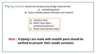
  • 43. Piping system should not introduce any foreign materials like a) corroded particles b) Scale or Broken pieces of broken seal material a) Stainless steel b) GFRP ( Glass fibre – reinforced polymers) c) Plastic lined stainless steel Note : If piping's are made with metallic parts should be earthed to prevent their anodic corrosion.
  • 44. Storage Tank of electrolyte Required minimum capacity of electrolyte tank is about 500 gallons for each 10,000 A of current. Generally contains three compartments  Reaction products from the electrolyte are separated by natural sedimentation in first. Electrolyte is then made to go into second via filters for further cleaning In last compartment filter removes rest of the particles before entering into piping system. A single tank is not recommended because of loss of time and wastage of electrolyte during draining, cleaning, mixing or during filling of new electrolyte in tank
  • 45. More than one tank is required and their number will depend on the range of electrolytes needed to meet the work load. Concrete tank or swimming pool types of tank are pleaded because of their low cost ,easy maintenance and reliability.
  • 47. Tool (cathode)  The most commonly used tool material are copper, brass, titanium, copper tungsten and stainless steels when electrolyte is made of salts of sodium and potassium.  Titanium has been found to be the most suitable tool where the electrolyte has the tendency to anodize the tool as in case of sulphuric acid.  The other tool materials are aluminium, graphite, bronze, platinum and tungsten carbide.  The accuracy of tool shape directly affects the work-piece accuracy.  Electro-forming and cold forging are two methods of tool shaping. a) Bare tool b) Coated tool c) Bit type tool
  • 49.  The general requirements of tool material in ECM are: 1. It should be conductor of electricity. 2. It should be rigid enough to take up the load due to fluid pressure. 3. It should be chemically inert to the electrolyte. 4. It should be easily machinable to make it in the desired shape.
  • 50. Faradays law for MRR calculation  The first law states that the amount of electrochemical dissolution or deposition is proportional to amount of charge passed through the electrochemical cell, which may be expressed as: m ∝ Q m = mass of material dissolved or deposited Q = amount of charge passed  The second law states that the amount of material deposited or dissolved further depends on Electrochemical Equivalence (ECE) of the material that is again the ratio of the atomic weigh and valency. Thus m ∝ E ∝ (A/Z)
  • 51. I = current ρ= density of the material F = Faraday’s constant = 96500 coulombs Q=It
  • 52. Process Parameters Electrolyte Material NaCl and NaNO3 Temperature 20 – 50 degree Flow rate 20 lpm per 100 A current Pressure 0.5 to 20 bar Dilution 100 g/l to 500 g/l Power Supply Type direct current Direct current Voltage 2 to 35 V Current 50 to 40,000 A Current density 0.1 A/mm2 to 5 A/mm2
  • 53. • Working gap 0.1 mm to 2 mm • Overcut 0.2 mm to 3 mm • Feed rate 0.5 mm/min to 15 mm/min • Electrode material Copper, brass, bronze • Surface roughness, Ra 0.2 to 1.5 μm
  • 54. Advantages 1. There is no cutting forces therefore clamping is not required except for controlled motion of the work piece. 2. It can machine configurations which is beyond the capability of conventional machining processes. 3. Very accurate (tolerance of ±0.02 mm). 4. Relatively fast. 5. Can machine harder metals than the tool. 6. Extremely thin materials can be easily worked without distortion. 7. Tool wear is nearly absent. 8. Better surface finish (0.2 to 0.8 micron). 9. Machining is done at low voltages, compared to other processes, with high metal removal rates. 10. Very small dimensions up to 0.05 mm can be controlled. 11. Complicated profiles can be machined easily in a single operation
  • 55. Disadvantages and Limitations A huge amount of energy is consumed (about 100 times that required for turning or drilling steel).  ECM can only be applied to electrically conductive work-piece materials.  The work-piece needs to be cleaned and oiled immediately after machining. The pumping of high-pressure electrolyte into the narrow machining gap gives rise to large forces acting on the tool and the workpiece. It is not easy to duplicate the shape of the tool electrode in the workpiece with a high degree of accuracy because of the side machining effect.
  • 56. Applications 1. The most common application of ECM is high accuracy duplication. 2. It is commonly used on thin walled, easily deformable and brittle material because they would probably develop cracks with conventional machining. 3. It is used in machining of hard-heat-resisting alloys. 4. It is used in cutting cavities and holes in various products, machining of complex external shapes like that of turbine blades, aerospace components and machining of tungsten carbide and nozzles of alloy steels. 5. Any conducting material can be machined by this method.
  • 57. Typical Parts made by ECM a) Turbine blade made of nickel alloy, note the shape of electrode
  • 58. b) Thin slots on 4340-steel roller-bearing cage. c) Integral airfoil structures on a compressor disk Die sinking Profiling and contouring
  • 60. Surface finish Variations in Surface finish occurs due to many reasons 1. Workpiece characteristics Irregular distribution of current density occurs, thus leaving the microscopic peaks and valleys that form the surface roughness. Due to these
  • 61. The mechanism of surface formation can be understood from following figure: The figure shows the effect of machining feed rate on the local gap width for an alloy containing two elements X and Y. Due to the difference in their machining rates and gap width, the generated maximum peak-to-valley surface roughness Rt decreases at higher feed rates, and thus better surfaces are expected at these higher rates.
  • 62. More fine grained and homogenous structures produce a better surface quality. The roughness obtained with the larger grain size of the annealed carbon steel (Fig), was due to the reduced number of grain boundaries present on such a surface. Effect of Heat treatment on surface roughness Annealing Normalising Hardening Case hardening Nitriding
  • 63. 1. Large grains cause a rougher finish than fine grains. 2. Insoluble inclusions such as graphite in cast iron increase roughness and create machining problems. 3. Variations in workpiece composition, as in the case of hardened steel, cause differences in local machining rates. 4. Precipitation of intermetallic compounds at grain boundaries leads to serious intergranular attack. Some reasons for poor surface finish
  • 64. In non-passivating electrode systems, the reduction in electrolyte concentration and the increase of its temperature improve the quality of surfaces. In passivating systems, low electrolyte concentration and a rise in its temperature increase the formation of a protective layer that causes deterioration to the surface quality. Increase in current density breaks up this layer so that there is a decrease in the percentage of the covered surface areas where the reaction of a non removing effect occurs and a smoother surface is produced.
  • 65. Accuracy of ECM  A small gap width represents a high degree of process accuracy. As can be seen in Fig. , the accuracy of machined parts depends on the current density, which is affected by 1. Material equivalent and gap voltage 2. Feed rate and gap phenomena including passivation 3. Electrolyte properties including rate, pH, temperature, concentration, pressure, type, and velocity For high process accuracy, machining conditions leading to narrow machining gaps are recommended. These include use of 1. A high feed rate 2. High-conductivity electrolytes 3. Passivating electrolytes, such as NaNO3, that have a low throwing power 4. Tool insulation that limits the side-machining action
  • 68. 1. For ECM of steel which is used as the electrolyte (a) kerosene (b) NaCl (c) Deionised water (d) HNO3 2. MRR in ECM depends on (a) Hardness of work material (b) atomic weight of work material (c) thermal conductivity of work material (d) ductility of work material
  • 69. 3. ECM cannot be undertaken for (a) steel (b) Nickel based superalloy (c) Al2O3 (d) Titanium alloy 4. Commercial ECM is carried out at a combination of (a) low voltage high current (b) low current low voltage (c) high current high voltage (d) low current low voltage
  • 71. Topics need to be discussed Electrochemical Deburring Electrochemical Grinding Electrochemical Honing Chemical Machining
  • 72. Electrochemical Deburring  When machining metal components, it is necessary to cross-drill holes to interconnect bores. Hydraulic valve bodies are a typical example where many drilled passages are used to direct the fluid flow. The intersection of these bores creates burrs, which must be removed Figure shows conventionally cut parts that require deburring.
  • 73. In the 1970s the thermal energy method (TEM) was introduced to remove burrs in hard- to-reach places. In this method, burrs are hit by 2760°C blast of heat for milliseconds, which burns them away, leaving everything else including threads, dimensions, surface finish, and the physical properties of the part intact. Parts subjected to TEM should be cleaned of oil and metal chips to avoid the formation of carbon smut or the vaporization of chips.
  • 74. Burrs can be removed using several other methods  Vibratory and Barrel finishing  Tumbling,  Water blasting  Application of ultrasound and abrasive slurry.  Abrasive flow machining (AFM) The drawbacks of these methods include lack of reliability, low metal removal rates, and contamination of surfaces with grit. AFM can reach inaccessible areas and machine multiple holes, slots, or edges in one operation. It actually devised for deburring of hydraulic valve spools and bodies and polishing of extrusion dies
  • 75. 1. In electrochemical deburring (ECDB), the anodic part to be deburred is placed in a fixture, which positions the cathodic electrode in close proximity to the burrs. 2. The electrolyte is then directed, under pressure, to the gap between the cathodic deburring tool and the burr. 3. On the application of the machining current, the burr dissolves forming a controlled radius. Since the gap between the burr and the electrode is minimal, burrs are removed at high current densities. 4. ECDB, therefore, changes the dimensions of the part by removing burrs leaving a controlled radius. Mechanism of deburring. ECDB can be applied to gears, spline shafts, milled components, drilled holes, and punched blanks. The process is particularly efficient for hydraulic system components such as spools, and sleeves of fluid distributors.