


GRID CONNECTED PV SYSTEM & RAPS
- 1. SOLAR ENERGY GRID CONNECTION:SYSTEM DESIGN AND RAPS By, Niroshini K Swathi Arasi S N Rajalaxmi T
- 2. GRID CONNECTED PV SYSTEM ❖ A system connected to the utility grid is known as a grid- connected energy system or a grid-connected PV system. ❖ Through this grid-tied connection, the system can capture solar energy, transform it into electrical power, and supply it to the homes where various electronic devices can use it. ❖ When the grid connected PV system is installed on residential or commercial rooftops, it provides solar electricity to all the electrical ports and sockets.
- 3. COMPONENTS OF GRID CONNECTED PV SYSTEM There are five main components involved in the making of a grid-connected solar system. 1. SOLAR PANELS 2. SOLAR INVERTER 3. NET METER (BIDIRECTIONAL METER) 4. GRID 5. MOUNTING STRUCTURES
- 4. GRID CONNECTED SOLAR SYSTEM
- 6. Solar Panels in Series of Same Characteristics • In this method ALL the solar panels are of the same type and power rating. The total voltage output becomes the sum of the voltage output of each panel. Using the same three 6 volt, 3.0 amp panels , • These PV panels are connected together in series, the array will produce an output voltage of 18 Volts (6 + 6 + 6) at 3.0 Amperes, giving 54 Watts (volts x amps) at full sun.
- 7. Solar Panels in Series of Different Voltages • In this method all the solar panels are of different types and power rating but have a common current rating. When they are connected together in series, the array produces 21 volts at 3.0 amps, or 63 watts. The voltage output jumps to 21 volts (5 + 7 + 9) .
- 8. Solar Panels in Series of Different Currents • In this method all the solar panels are of different types and power rating. The individual panel voltages will add together as before, but this time the amperage will be limited to the value of the lowest panel in the series string, in this case 1 Ampere. Then the array will produce 19 Volts (3 + 7 + 9) at 1.0Ampere only, or only 19 watts. • The solar panel rated at 9 volts, 5 amps, will only use one fifth or 20% of its maximum current potential reducing its efficiency
- 9. Solar Panels in Parallel of Same Characteristics • In this method ALL the solar panels are of the same type and power rating. Using the same three 6 Volt, 3.0 Amp panels as above, the total output of the panels, when connected together in parallel, the output voltage still remains at the same value of 6 volts, but the total amperage has now increased to 9.0Amperes (3 + 3 + 3), producing 54 watts at full sun.
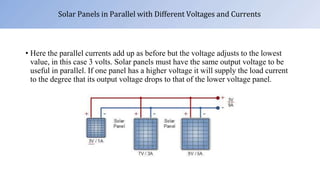
- 10. Solar Panels in Parallel with Different Voltages and Currents • Here the parallel currents add up as before but the voltage adjusts to the lowest value, in this case 3 volts. Solar panels must have the same output voltage to be useful in parallel. If one panel has a higher voltage it will supply the load current to the degree that its output voltage drops to that of the lower voltage panel.
- 11. SOLAR POWER INVERTER • The Solar Power Inverter provides that DC toAC conversion using electronic switching techniques. • The inverter allows us to run electric drills, computers, vacuum cleaners, mains lighting, and most electrical appliances that can be plugged into the wall sockets. If the power inverter is big enough, then larger appliances such as freezers, refrigerators, and washing machines can also be used.
- 12. INVERTER CONFIGURATION • Central Inverter Configuration – Several branches of the array are connected together in parallel. The complete output of the array is converted toAC through a single central solar power inverter and then fed to the grid.
- 13. • Branch Inverter Configuration – Each branch or string has its own inverter attached. Then each single branch can have a different number of PV panels, different panel types, positions, orientations or suffer from full or partial shading. The result is that each inverter produces a different power output relative to its connected array.
- 14. • Individual Inverter Configuration – Each photovoltaic solar panel has its own power inverter. This enables the inverter to select the optimum power point for the panel giving very good efficiency but at a higher cost per kWp. More components in the array means lower reliability and more maintenance.
- 15. SIZE OF SOLAR ARRAY • Electrical power is the product of the panels voltage and its output current, as P = V x I. • The size of the photovoltaic system required varies from home to home as each homes energy usage and energy efficiency will be different. Step 1. – Determine the Suns Peak HoursAvailable Per Day • If the average peak sun hours for a particular location is given as 4.5 hours, this means then that our solar panel will provide 4500 watt-hours a day of peak electricity during the day. Energy available in the solar panel =4.5 hrs x 1000 W
- 16. Step 2. – Determine Your Energy Needs In Terms Of Watts Per Hour To determine the required overall power rating of a photovoltaic solar system required to power a home, the electrical energy needs in terms of watts per hour should be evaluated. Step 3. – Optimize Your Power Demands and Usage An energy-efficient home reduces the number of solar panels required making the installation of the system cheaper, less complicated. Step 4. – Determine The Type of Solar Panels You Wish To Use The number and type of solar panels required to capture enough solar energy to support your electrical consumption plays an important role in the design, sizing, operating voltage and cost of your solar photovoltaic system.
- 17. Step 5. – Size Your Array The total wattage of solar energy provides the total number of solar panels required to generate a given amount of Watt-hours (or kWh) for particular application. For example, Crompton HS Plus 1200 mm (48 inch) High Speed Energy Efficient 53W Ceiling Fan (Opal White).If we consider the fan runs for around 4hr. Then energy consumption by fan E is = 53*4=212 Whr/day Where one solar panel produces 250 watt power , then the number of solar panel required is, =212/4.5 =47.11W Then we can use a single solar panel of around 50W.
- 18. TYPES OF GRID CONNECTED PV SYSTEM □ON-GRID SYSTEMS □ON-GRID SYSTEMS WITHABATTERY BACKUP
- 19. ADVANTAGES OF GRID CONNECTED PV SYSTEM • Systems such as Net metering and Feed-in-Tariff which are offered by some system operators, can offset a customers electricity usage costs. • Grid-connected PV systems are comparatively easier to install as they do not require a battery system. • Grid interconnection of photovoltaic (PV) power generation systems has the advantage of effective utilization of generated power because there are no storage losses involved. • A photovoltaic power system is carbon negative over its lifespan, as any energy produced over and above that to build the panel initially offsets the need for burning fossil fuels. Even though the sun doesn't always shine, any installation gives a reasonably predictable average reduction in carbon consumption.
- 20. DISADVANTAGES OF GRID CONNECTED PV SYSTEM • Grid-connected PV can cause issues with voltage regulation. But electricity injected into the grid increases voltage, and can drive levels outside the acceptable bandwidth of ±5%. • Grid-connected PV can compromise power quality. PV’s intermittent nature means rapid changes in voltage. This not only wears out voltage regulators due to frequent adjusting, but also can result in voltage flicker. • Connecting to the grid poses many protection-related challenges.
- 21. ISLANDING Islanding is the condition in which a distributed generator continues to power a location even though power from the electric utility grid is no longer present. Islanding can be dangerous to utility workers, who may not realize that a circuit is still powered, even though there is no power from the electrical grid . For that reason, distributed generators must detect islanding and immediately stop producing power; this is referred to as anti-islanding
- 22. ANTI-ISLANDING • In the case of a utility blackout in a grid-connected PV system, the solar panels will continue to deliver power as long as the sun is shining. In this case, the supply line becomes an "island" with power surrounded by a "sea" of unpowered lines. For this reason, solar inverters that are designed to supply power to the grid are generally required to have automatic anti-islanding circuitry in them. In intentional islanding, the generator disconnects from the grid, and forces the distributed generator to power the local circuit. This is often used as a power backup system for buildings that normally sell their power to the grid.
- 23. ISLANDING
- 24. DESIGN CONSIDERATION FOR GRID CONNECTED PV SYSTEM • Determine the solar access for the site • Determine whether any shading will occur and estimate its effect • Determine the orientation and tilt angle of the roof • Determine the available area of solar array • Determine whether roof is suitable for mounting the array • Determine how the modules are arranged in roof • Determine whether the inverter will be located. • Determine cable route and estimate the length of cable
- 25. ANALYSIS OF CLIMATIC CONDITION OF THE LOCATION □Know the climatic conditions to install the solar panel based on Monthly average daily normal radiation, Monthly average clear sky insolation, Monthly average sunshine hours, Daily sunshine hours, Monthly average wind speed ,Monthly average air temperature etc. SELECTION OF COMPONENTS □It should follow certain standards for system design for solar PV module , Inverter , Cables , Connectors , Module mounting structure, Lightning arrestor , Weather monitoring system ,Fuses , Supervisory control and data acquisition.
- 26. DESIGNING A PV SYSTEM BASED ON ENERGY BALANCE • Energy generated = Energy consumed • The energy yield at DC side is EDC=A⌠GM Ꞃ-------------------------------------------(1) Total module areaA=NT XAM NT - No of modules • The required energy balance EDC=ELXSF---------------------------------------------(2) SF-Sizing factor (i.e. 1.1) EL - Energy yield at load side
- 27. •
- 28. •
- 29. 2) Effective voltage • Minimum effective voltage • Maximum effective voltage 3) No of modules in a string • Minimum No of modules
- 30. • Maximum No of modules 4) Short circuit current of the module • Matching best combination of string and array to get best power output • Maximum number of strings to be connected with inverter
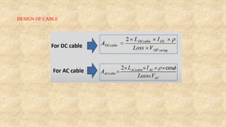
- 31. DESIGN OF CABLE
- 32. THANK YOU
- 33. Remote Area Power Supply ▪ Areas without a power electricity supply are where a Stand Alone Power System (SAPS or SPS), also known as Remote Area Power Supply (RAPS), are utilized. ▪ A stand alone system is an off grid solar PV system. Off grid or stand alone systems are not linked to the local electric grid. The solar panels in a stand alone solar system are used to charge a bank of batteries rather than being connected to the grid. ▪ An off-grid or Stand Alone PV System is made up of a number of individual photovoltaic modules (or panels) usually of 12 volts with power outputs of between 50 and 100+ watts each. ▪ It consisting of and array of one or more PV modules, conductors, electrical components, and one or more loads. 1
- 34. Presentation outline ▪ COMPONENTS OF STAND ALONE PV SYSTEM • Solar panels • Solar battery • Solar inverter • Charge controller • Wirings ▪ SYSTEM DESIGN APPROACH OF STAND ALONE PV SYSTEM 2
- 35. Schematic diagram of proposed off-grid solar photovoltaic system 3
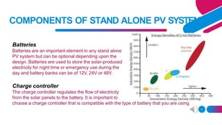
- 36. COMPONENTS OF STAND ALONE PV SYSTEM Batteries Batteries are an important element in any stand alone PV system but can be optional depending upon the design. Batteries are used to store the solar-produced electricity for night time or emergency use during the day and battery banks can be of 12V, 24V or 48V. Charge controller The charge controller regulates the flow of electricity from the solar panels to the battery. It is important to choose a charge controller that is compatible with the type of battery that you are using. 4
- 37. COMPONENTS OF STAND ALONE PV SYSTEM • To ensure that the electrical parameters present at the battery are kept within the specifications given by battery manufacturer. • When the sun radiation is excessive during summer , the generated PV power exceeds the load. This excess energy is sent to battery. • When the battery is fully charged, the charge controller play a critical role in “DE-COUPLING” the PV array from the battery. • A charge controller that contains a proper current regulation is also able to control the C-rate. 5 • Finally, the charge controller can impose the limits on the maximal current flowing into and from the battery. Function of Charge controller Battery parameters like State of charge Depth of discharge Cycle lifetime
- 38. COMPONENTS OF STAND ALONE PV SYSTEM Fuses and Isolation Switches • These allow PV installations to be protected from accidental shorting of wires allowing power from the PV modules and 6 system to be turned “OFF” when not required saving energy and improving battery life. Inverter • The inverter can be another optional unit in a stand alone system. Inverters are used to convert the 12V, 24V or 48 Volts direct current (DC) power from the solar array and batteries into an alternating current (AC) electricity and power of either 120 VAC or 240 VAC for use in the home to power AC mains appliances such as TV’s, washing machines, freezers, etc.
- 39. COMPONENTS OF STAND ALONE PV SYSTEM Solar panels • Solar panels are many individual solar cells that convert sunlight into electricity. The more sunlight hits the solar cells, the more electricity they generate. Solar panels are usually mounted on the roof of a home or building, but they can also be mounted on the ground. Wiring • The final component required in and PV solar system is the electrical wiring. The cables need to be correctly rated for the voltage and power requirements. 7
- 42. A simple approach for designing off- grid system ❖ Total load current and operational time ❖ System losses ❖ Solar irradiation in daily equivalent sun hours(ESH) ❖ Total solar array current requirements ❖ Optimum module arrangement for solar array ❖ Battery size for recommended reserve time 10
- 43. DESIGN PRINCIPLE OF RAPS DESIGN PRINCIPLES DEPENDS ON □ Storage component a) Required number of autonomy b) c) Efail Edump 11
- 44. SIZING BASED ON RELIABILITY OF SUPPLY ❑ One way to quantify the reliability of supply is by a parameter known as the loss-of load probability (LLP). ❑ LLP is the ratio between the estimated energy deficit and the energy demand over the total operation time of the installation. ❑ Lower the LLP, more stable and reliable the PV system would be. EL = year Efail LLP = 12
- 45. SIZING BASED ON RELIABILITY OF SUPPLY 13
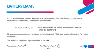
- 46. BATTERY BANK ❑ Battery bank is the workhorse of any off- grid system, because it is stable power source. ❑ It is thus very important to understand how the battery bank will act in the PV system. ❑ To know how a battery works the net effect of all the forces that try to charge or discharge the battery need to be understood. VOC-BB will not be constant, but a function of the state of charge, the ambient temperature, and others. I-V curve of an idealised battery bank IBB-Ch CHARGING REGIME DISCHARGING REGIME 14 VBB-ds Current,I IBB-Dis VBB-CH VOC-BB
- 47. BATTERY BANK 15
- 48. BATTERY BANK Consequently, ẞ=0 means that the PV system is not active, for example during night. In a similar manner. The power on the left and right hand side of the inverter: 16
- 49. BATTERYBANK Clearly, a=0 indicates that no load is present 17
- 50. BATTERY BANK 18
- 51. 19 Designing a system with energy balance An adequate number of days of autonomy (dA) need to be selected depending the location and a basic understanding of weather pattern. The rated energy of the chosen batteries is Ebat =VOC-batCbat where Cat is the battery capacity (unit Ampere-hours).
- 52. Adjustment of the batteries 20
- 53. PV side of the system 21
- 54. Photovoltaic water pumping system • System can pump water from depths of 20-100 meters • Supply water from 500 - 50000 litres/day •PV system supplies power through a dc-ac inverter to an electric motor coupled to a submersible pump. 22