SlideShare a Scribd company logo
Industrial Computer Application, Chapter III: Relay Logic Diagrams
© 2020, UKH, Dr.Ibrahim Ismael Hamarash, ibrahim.hamad@ukh.edu.krd
Industrial Computer Application
Chapter III
Relay Logic Diagrams
Professor Dr. Ibrahim Hamarash
ibrahim.hamad@ukh.edu.krd
Industrial Computer Application, Chapter III: Relay Logic Diagrams
© 2020, UKH, Dr.Ibrahim Ismael Hamarash, ibrahim.hamad@ukh.edu.krd
The Binary Concept
✓ The PLC, like all digital equipment, operates on the binary
principle.
✓ The term binary principle refers to the idea that many things
can be thought of as existing in only one of two states. These
states are 1 and 0. The 1 and 0 can represent ON or OFF, open
or closed, true or false, high or low, or any other two conditions.
✓ The key to the speed and accuracy with which binary
information can be processed is that there are only two states,
each of which is distinctly different. There is no in-between
state so when information is processed the outcome is either
yes or no.
Industrial Computer Application, Chapter III: Relay Logic Diagrams
© 2020, UKH, Dr.Ibrahim Ismael Hamarash, ibrahim.hamad@ukh.edu.krd
The Logic Gate
A logic gate is a circuit with several inputs but only one
output that is activated by particular combinations of input
conditions.
The two-state binary concept, applied to gates, can be the
basis for making decisions.
Logic is the ability to make decisions when one or more
different factors must be taken into account before an
action is taken. This is the basis for the operation of the
PLC, where it is required for a device to operate when
certain conditions have been met.
Industrial Computer Application, Chapter III: Relay Logic Diagrams
© 2020, UKH, Dr.Ibrahim Ismael Hamarash, ibrahim.hamad@ukh.edu.krd
Example:
The high beam automobile lighting circuit of example of a
logical AND decision. For this application, the high beam
light can be turned on only when the light witch AND the
high beam switch are closed.
Example:
The dome light automobile circuit of Figure 4-2 is an
example of a logical OR decision. For this application, the
dome light will be turned on whenever the passenger door
switch OR the driver door switch is activated.
Industrial Computer Application, Chapter III: Relay Logic Diagrams
© 2020, UKH, Dr.Ibrahim Ismael Hamarash, ibrahim.hamad@ukh.edu.krd
Logical Functions
✓ The operations performed by digital equipment are
based on three fundamental logic functions: AND, OR,
and NOT. Each function has a rule that will determine .
✓ the outcome and a symbol that represents the operation.
For the purpose of this discussion, the outcome or output is called
Y and the signal inputs are called A, B, C,
and so on. Also, binary 1 represents the presence of a
signal or the occurrence of some event, and binary 0
represents the absence of the signal or nonoccurrence
of the event
Industrial Computer Application, Chapter III: Relay Logic Diagrams
© 2020, UKH, Dr.Ibrahim Ismael Hamarash, ibrahim.hamad@ukh.edu.krd
The AND Function
Industrial Computer Application, Chapter III: Relay Logic Diagrams
© 2020, UKH, Dr.Ibrahim Ismael Hamarash, ibrahim.hamad@ukh.edu.krd
The OR Function
Industrial Computer Application, Chapter III: Relay Logic Diagrams
© 2020, UKH, Dr.Ibrahim Ismael Hamarash, ibrahim.hamad@ukh.edu.krd
The NOT Function
Industrial Computer Application, Chapter III: Relay Logic Diagrams
© 2020, UKH, Dr.Ibrahim Ismael Hamarash, ibrahim.hamad@ukh.edu.krd
Example (NAND, NOR)
Industrial Computer Application, Chapter III: Relay Logic Diagrams
© 2020, UKH, Dr.Ibrahim Ismael Hamarash, ibrahim.hamad@ukh.edu.krd
The XOR Function
Industrial Computer Application, Chapter III: Relay Logic Diagrams
© 2020, UKH, Dr.Ibrahim Ismael Hamarash, ibrahim.hamad@ukh.edu.krd
The Boolean Algebra
✓ The mathematical study of the binary
number system and logic is called
Boolean algebra.
✓ The purpose of this algebra is to
provide a simple way of writing
complicated combinations of logic
statements. There are many
applications where Boolean algebra
could be applied to solving PLC
programming problems.
Industrial Computer Application, Chapter III: Relay Logic Diagrams
© 2020, UKH, Dr.Ibrahim Ismael Hamarash, ibrahim.hamad@ukh.edu.krd
The Boolean Equation
✓ PLC digital systems may be designed
using Boolean algebra. Circuit
functions are represented by Boolean
equations.
✓ The figure illustrates how logic
operators AND, NAND, OR, NOR, and
NOT are used singly to form logical
statements.
✓ The figure illustrates how basic logic
operators are used in combination to
form Boolean equations
Industrial Computer Application, Chapter III: Relay Logic Diagrams
© 2020, UKH, Dr.Ibrahim Ismael Hamarash, ibrahim.hamad@ukh.edu.krd
The Boolean Algebra Laws
Industrial Computer Application, Chapter III: Relay Logic Diagrams
© 2020, UKH, Dr.Ibrahim Ismael Hamarash, ibrahim.hamad@ukh.edu.krd
Example: Developing logic gate circuit from Boolean
Expression
Y=A (BC+D)
Industrial Computer Application, Chapter III: Relay Logic Diagrams
© 2020, UKH, Dr.Ibrahim Ismael Hamarash, ibrahim.hamad@ukh.edu.krd
The Hardwired Logic
The term hardwired logic refers to logic
control functions
that are determined by the way devices
are electrically interconnected. Hardwired
logic can be implemented using relays and
relay ladder schematics. Relay ladder
schematics are universally used and
understood in industry.
Hardwired logic is fixed; it is changeable
only by altering the way devices are
electrically interconnected.
Industrial Computer Application, Chapter III: Relay Logic Diagrams
© 2020, UKH, Dr.Ibrahim Ismael Hamarash, ibrahim.hamad@ukh.edu.krd
The Hardwired Logic, cont.
A typical relay ladder schematic of a
motor stop/start control station with pilot lights is
shown in this diagram. The control scheme is drawn
between two vertical supply lines. All the
components are placed between these two lines,
called rails or legs, connecting the two power lines
with what look like rungs of a ladder—thus the name,
relay ladder schematic
Industrial Computer Application, Chapter III: Relay Logic Diagrams
© 2020, UKH, Dr.Ibrahim Ismael Hamarash, ibrahim.hamad@ukh.edu.krd
The Programmable Control
The programmable control is based on the basic logic
functions, which are programmable and easily changed.
These functions (AND, OR, NOT) are used either singly or in
combinations to form instructions that will determine if a
device is to be switched on or off. The form in which these
instructions are implemented to convey commands
to the PLC is called the language.
The most common PLC language is ladder logic.
shows a typical ladder logic program for the motor start/stop
circuit. The instructions used are the relay equivalent of
normally open (NO) and normally closed (NC) contacts and coils
Industrial Computer Application, Chapter III: Relay Logic Diagrams
© 2020, UKH, Dr.Ibrahim Ismael Hamarash, ibrahim.hamad@ukh.edu.krd
Example: The Programmable Control
This diagram shows a typical ladder logic
program for the motor start/stop circuit. The
instructions used are the relay equivalent of
normally open (NO) and normally closed (NC)
contacts and coils
Industrial Computer Application, Chapter III: Relay Logic Diagrams
© 2020, UKH, Dr.Ibrahim Ismael Hamarash, ibrahim.hamad@ukh.edu.krd
Notes
✓ PLC contact symbolism is a simple way of expressing
the control logic in terms of symbols. These symbols are
basically the same as those used for representing hardwired relay
control circuits. A rung is the contact symbolism required to
control an output.
✓ Some PLCs allow a rung to have multiple outputs while others allow
only one output per rung. A complete ladder logic program then
consists of several rungs, each of which controls an output.
✓ In programmed logic all mechanical switch contacts are
represented by a software contact symbol and all electromagnetic
coils are represented by a software coil symbol.
Industrial Computer Application, Chapter III: Relay Logic Diagrams
© 2020, UKH, Dr.Ibrahim Ismael Hamarash, ibrahim.hamad@ukh.edu.krd
Examples:
The relationship between
the relay ladder schematic,
the ladder logic program,
and the equivalent logic gate
circuit.
LS: Limit Switch
SOL: Solenoid
PL: Pilot Lamp
PS: Push Button
Industrial Computer Application, Chapter III: Relay Logic Diagrams
© 2020, UKH, Dr.Ibrahim Ismael Hamarash, ibrahim.hamad@ukh.edu.krd
Examples:
The relationship
between the relay
ladder schematic, the
ladder logic program,
and the equivalent logic
gate circuit.
LS: Limit Switch
FS: Flow Switch
PL:Pilot Lamp
Industrial Computer Application, Chapter III: Relay Logic Diagrams
© 2020, UKH, Dr.Ibrahim Ismael Hamarash, ibrahim.hamad@ukh.edu.krd
Examples:
The relationship between
the relay ladder schematic,
the ladder logic program,
and the equivalent logic gate
circuit.
Industrial Computer Application, Chapter III: Relay Logic Diagrams
© 2020, UKH, Dr.Ibrahim Ismael Hamarash, ibrahim.hamad@ukh.edu.krd
Programming Word Level Logic
Instructions
Most PLCs provide word-level logic instructions as
part of their instruction set.
The figure illustrates the operation of the AND
instruction to perform a word-level AND operation
using the bits in the two source addresses. This
instruction tells the processor to perform an AND
operation on B3:5 and B3:7 and to store the result in
destination B3:10 when input device A is true. The
destination bits are a result of the logical AND
operation.
Industrial Computer Application, Chapter III: Relay Logic Diagrams
© 2020, UKH, Dr.Ibrahim Ismael Hamarash, ibrahim.hamad@ukh.edu.krd
Programming Word Level Logic Instructions
The figure illustrates the operation of a word-level
OR instruction, which ORs the data in Source A, bit by
bit, with the data in Source B and stores the result at the
destination address. The address of Source A is B3:1,
the address of Source B is B3:2, and the destination
address is B3:20. The instruction may be programmed
conditionally, with input instruction(s) preceding it, or
unconditionally, as shown, without any input instructions
preceding it.
Industrial Computer Application, Chapter III: Relay Logic Diagrams
© 2020, UKH, Dr.Ibrahim Ismael Hamarash, ibrahim.hamad@ukh.edu.krd
Selecting the correct word logic instruction for different situations
If you want to . . .
. . . use this
instruction.
Know when matching bits in two different
words are both ON
AND
Know when one or both matching bits in two
different words are ON
OR
Know when one or the other bit of matching
bits in two different words is ON
XOR
Reverse the state of bits in a word NOT
Industrial Computer Application, Chapter III: Relay Logic Diagrams
© 2020, UKH, Dr.Ibrahim Ismael Hamarash, ibrahim.hamad@ukh.edu.krd
Reading List
Frank Petruzella, Programmable Logic Controllers, McGeaw Hill, 5th Ed.,
2017.
Austin Scott, Instant PLC Programming with RSLogix 5000, Packt
Publishers, 2013.
Websites
https://www.plcacademy.com
http://www.plcs.net
Industrial Computer Application, Chapter III: Relay Logic Diagrams
© 2020, UKH, Dr.Ibrahim Ismael Hamarash, ibrahim.hamad@ukh.edu.krd
Questions?

More Related Content

PPTX
pp-05-relay-logic-2.pptx................
PPTX
L3 Programmable logic controller
PDF
Introduction to automation
PPTX
Pe 5421 plc aftermid week 10 onwards
PPTX
Unit 4 - PLC.pptx
PDF
Plc documentation final
PPTX
CAM ladder logic diagram
PPTX
Programmable Logic Controller and ladder logic programming
pp-05-relay-logic-2.pptx................
L3 Programmable logic controller
Introduction to automation
Pe 5421 plc aftermid week 10 onwards
Unit 4 - PLC.pptx
Plc documentation final
CAM ladder logic diagram
Programmable Logic Controller and ladder logic programming

Similar to Industrial Computer Applications, ch-3 (20)

PDF
PPTX
Elements of Industrial Automation 20me43p
PDF
Plc intro
PDF
Plc intro
PDF
Plc intro
PPTX
Pe 3231 week 15 18 plc
DOCX
Programmable logic array
PPT
10617568.ppt
PPT
Chapter 2 ladder
PPTX
Introduction to automation ,plc, programing language
PDF
Elements of Industrial Automation Week 05 Notes.pdf
PPT
4597231dsafsfsafsafsfsafsfaffsdfdsfsfds.ppt
PDF
Chapter 3 - Basics of PLC Programming (1).pdf
PDF
PLC-Programmable-Logic-Controller-Book.pdf
PPTX
MECH - UNIT 4.pptx_PLC PERFORMANCE AND IMPORTANCE
PPTX
programmable logic Controller intro.pptx
PPTX
EEE303-Week02 - Boolean Algebra and Num.pptx
PPTX
Programmable Logic Controller
PPT
Pe 6441 advanced manufacturing lab ch4 wks 12 14
PDF
Modul PLC Programming.pdf
Elements of Industrial Automation 20me43p
Plc intro
Plc intro
Plc intro
Pe 3231 week 15 18 plc
Programmable logic array
10617568.ppt
Chapter 2 ladder
Introduction to automation ,plc, programing language
Elements of Industrial Automation Week 05 Notes.pdf
4597231dsafsfsafsafsfsafsfaffsdfdsfsfds.ppt
Chapter 3 - Basics of PLC Programming (1).pdf
PLC-Programmable-Logic-Controller-Book.pdf
MECH - UNIT 4.pptx_PLC PERFORMANCE AND IMPORTANCE
programmable logic Controller intro.pptx
EEE303-Week02 - Boolean Algebra and Num.pptx
Programmable Logic Controller
Pe 6441 advanced manufacturing lab ch4 wks 12 14
Modul PLC Programming.pdf
Ad

More from Salahaddin University-Erbil, University of Kurdistan Hewler (11)

PDF
Machine Learning-Ch.1: Introduction-v3.pdf
PDF
Signals & Systems-Ch-1: Introduction-v4.pdf
PDF
Special Topics in Software Engineering-Ch.1-v1.pdf
PDF
Software Architecture and Design-Ch-3-v6.pdf
PDF
Software Architecture and Design-Ch-2-v6.pdf
PDF
Software Architecture and Design-Ch-1.v6
PDF
Human Computer Interaction,Ch-1. Introduction to HCI.pdf
PDF
Robotics,ch1. Introduction to Robotic Systems.pdf
PDF
Software-Requirements, ch.1. Introduction.pdf
PDF
Industrial Computer Applications, ch-2
PDF
Machine Learning-Ch.1: Introduction-v3.pdf
Signals & Systems-Ch-1: Introduction-v4.pdf
Special Topics in Software Engineering-Ch.1-v1.pdf
Software Architecture and Design-Ch-3-v6.pdf
Software Architecture and Design-Ch-2-v6.pdf
Software Architecture and Design-Ch-1.v6
Human Computer Interaction,Ch-1. Introduction to HCI.pdf
Robotics,ch1. Introduction to Robotic Systems.pdf
Software-Requirements, ch.1. Introduction.pdf
Industrial Computer Applications, ch-2
Ad

Recently uploaded (20)

PDF
Addressing The Cult of Project Management Tools-Why Disconnected Work is Hold...
PPTX
Oracle E-Business Suite: A Comprehensive Guide for Modern Enterprises
PDF
Digital Systems & Binary Numbers (comprehensive )
PDF
Which alternative to Crystal Reports is best for small or large businesses.pdf
PDF
Softaken Excel to vCard Converter Software.pdf
PDF
Nekopoi APK 2025 free lastest update
PDF
T3DD25 TYPO3 Content Blocks - Deep Dive by André Kraus
PPTX
Reimagine Home Health with the Power of Agentic AI​
PDF
SAP S4 Hana Brochure 3 (PTS SYSTEMS AND SOLUTIONS)
PPTX
CHAPTER 2 - PM Management and IT Context
PDF
Adobe Illustrator 28.6 Crack My Vision of Vector Design
PDF
Raksha Bandhan Grocery Pricing Trends in India 2025.pdf
PDF
Wondershare Filmora 15 Crack With Activation Key [2025
PPTX
Agentic AI Use Case- Contract Lifecycle Management (CLM).pptx
PDF
Understanding Forklifts - TECH EHS Solution
PDF
How to Migrate SBCGlobal Email to Yahoo Easily
PPTX
L1 - Introduction to python Backend.pptx
PDF
Navsoft: AI-Powered Business Solutions & Custom Software Development
PPT
Introduction Database Management System for Course Database
PPTX
VVF-Customer-Presentation2025-Ver1.9.pptx
Addressing The Cult of Project Management Tools-Why Disconnected Work is Hold...
Oracle E-Business Suite: A Comprehensive Guide for Modern Enterprises
Digital Systems & Binary Numbers (comprehensive )
Which alternative to Crystal Reports is best for small or large businesses.pdf
Softaken Excel to vCard Converter Software.pdf
Nekopoi APK 2025 free lastest update
T3DD25 TYPO3 Content Blocks - Deep Dive by André Kraus
Reimagine Home Health with the Power of Agentic AI​
SAP S4 Hana Brochure 3 (PTS SYSTEMS AND SOLUTIONS)
CHAPTER 2 - PM Management and IT Context
Adobe Illustrator 28.6 Crack My Vision of Vector Design
Raksha Bandhan Grocery Pricing Trends in India 2025.pdf
Wondershare Filmora 15 Crack With Activation Key [2025
Agentic AI Use Case- Contract Lifecycle Management (CLM).pptx
Understanding Forklifts - TECH EHS Solution
How to Migrate SBCGlobal Email to Yahoo Easily
L1 - Introduction to python Backend.pptx
Navsoft: AI-Powered Business Solutions & Custom Software Development
Introduction Database Management System for Course Database
VVF-Customer-Presentation2025-Ver1.9.pptx

Industrial Computer Applications, ch-3

  • 1. Industrial Computer Application, Chapter III: Relay Logic Diagrams © 2020, UKH, Dr.Ibrahim Ismael Hamarash, ibrahim.hamad@ukh.edu.krd Industrial Computer Application Chapter III Relay Logic Diagrams Professor Dr. Ibrahim Hamarash ibrahim.hamad@ukh.edu.krd
  • 2. Industrial Computer Application, Chapter III: Relay Logic Diagrams © 2020, UKH, Dr.Ibrahim Ismael Hamarash, ibrahim.hamad@ukh.edu.krd The Binary Concept ✓ The PLC, like all digital equipment, operates on the binary principle. ✓ The term binary principle refers to the idea that many things can be thought of as existing in only one of two states. These states are 1 and 0. The 1 and 0 can represent ON or OFF, open or closed, true or false, high or low, or any other two conditions. ✓ The key to the speed and accuracy with which binary information can be processed is that there are only two states, each of which is distinctly different. There is no in-between state so when information is processed the outcome is either yes or no.
  • 3. Industrial Computer Application, Chapter III: Relay Logic Diagrams © 2020, UKH, Dr.Ibrahim Ismael Hamarash, ibrahim.hamad@ukh.edu.krd The Logic Gate A logic gate is a circuit with several inputs but only one output that is activated by particular combinations of input conditions. The two-state binary concept, applied to gates, can be the basis for making decisions. Logic is the ability to make decisions when one or more different factors must be taken into account before an action is taken. This is the basis for the operation of the PLC, where it is required for a device to operate when certain conditions have been met.
  • 4. Industrial Computer Application, Chapter III: Relay Logic Diagrams © 2020, UKH, Dr.Ibrahim Ismael Hamarash, ibrahim.hamad@ukh.edu.krd Example: The high beam automobile lighting circuit of example of a logical AND decision. For this application, the high beam light can be turned on only when the light witch AND the high beam switch are closed. Example: The dome light automobile circuit of Figure 4-2 is an example of a logical OR decision. For this application, the dome light will be turned on whenever the passenger door switch OR the driver door switch is activated.
  • 5. Industrial Computer Application, Chapter III: Relay Logic Diagrams © 2020, UKH, Dr.Ibrahim Ismael Hamarash, ibrahim.hamad@ukh.edu.krd Logical Functions ✓ The operations performed by digital equipment are based on three fundamental logic functions: AND, OR, and NOT. Each function has a rule that will determine . ✓ the outcome and a symbol that represents the operation. For the purpose of this discussion, the outcome or output is called Y and the signal inputs are called A, B, C, and so on. Also, binary 1 represents the presence of a signal or the occurrence of some event, and binary 0 represents the absence of the signal or nonoccurrence of the event
  • 6. Industrial Computer Application, Chapter III: Relay Logic Diagrams © 2020, UKH, Dr.Ibrahim Ismael Hamarash, ibrahim.hamad@ukh.edu.krd The AND Function
  • 7. Industrial Computer Application, Chapter III: Relay Logic Diagrams © 2020, UKH, Dr.Ibrahim Ismael Hamarash, ibrahim.hamad@ukh.edu.krd The OR Function
  • 8. Industrial Computer Application, Chapter III: Relay Logic Diagrams © 2020, UKH, Dr.Ibrahim Ismael Hamarash, ibrahim.hamad@ukh.edu.krd The NOT Function
  • 9. Industrial Computer Application, Chapter III: Relay Logic Diagrams © 2020, UKH, Dr.Ibrahim Ismael Hamarash, ibrahim.hamad@ukh.edu.krd Example (NAND, NOR)
  • 10. Industrial Computer Application, Chapter III: Relay Logic Diagrams © 2020, UKH, Dr.Ibrahim Ismael Hamarash, ibrahim.hamad@ukh.edu.krd The XOR Function
  • 11. Industrial Computer Application, Chapter III: Relay Logic Diagrams © 2020, UKH, Dr.Ibrahim Ismael Hamarash, ibrahim.hamad@ukh.edu.krd The Boolean Algebra ✓ The mathematical study of the binary number system and logic is called Boolean algebra. ✓ The purpose of this algebra is to provide a simple way of writing complicated combinations of logic statements. There are many applications where Boolean algebra could be applied to solving PLC programming problems.
  • 12. Industrial Computer Application, Chapter III: Relay Logic Diagrams © 2020, UKH, Dr.Ibrahim Ismael Hamarash, ibrahim.hamad@ukh.edu.krd The Boolean Equation ✓ PLC digital systems may be designed using Boolean algebra. Circuit functions are represented by Boolean equations. ✓ The figure illustrates how logic operators AND, NAND, OR, NOR, and NOT are used singly to form logical statements. ✓ The figure illustrates how basic logic operators are used in combination to form Boolean equations
  • 13. Industrial Computer Application, Chapter III: Relay Logic Diagrams © 2020, UKH, Dr.Ibrahim Ismael Hamarash, ibrahim.hamad@ukh.edu.krd The Boolean Algebra Laws
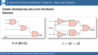
  • 14. Industrial Computer Application, Chapter III: Relay Logic Diagrams © 2020, UKH, Dr.Ibrahim Ismael Hamarash, ibrahim.hamad@ukh.edu.krd Example: Developing logic gate circuit from Boolean Expression Y=A (BC+D)
  • 15. Industrial Computer Application, Chapter III: Relay Logic Diagrams © 2020, UKH, Dr.Ibrahim Ismael Hamarash, ibrahim.hamad@ukh.edu.krd The Hardwired Logic The term hardwired logic refers to logic control functions that are determined by the way devices are electrically interconnected. Hardwired logic can be implemented using relays and relay ladder schematics. Relay ladder schematics are universally used and understood in industry. Hardwired logic is fixed; it is changeable only by altering the way devices are electrically interconnected.
  • 16. Industrial Computer Application, Chapter III: Relay Logic Diagrams © 2020, UKH, Dr.Ibrahim Ismael Hamarash, ibrahim.hamad@ukh.edu.krd The Hardwired Logic, cont. A typical relay ladder schematic of a motor stop/start control station with pilot lights is shown in this diagram. The control scheme is drawn between two vertical supply lines. All the components are placed between these two lines, called rails or legs, connecting the two power lines with what look like rungs of a ladder—thus the name, relay ladder schematic
  • 17. Industrial Computer Application, Chapter III: Relay Logic Diagrams © 2020, UKH, Dr.Ibrahim Ismael Hamarash, ibrahim.hamad@ukh.edu.krd The Programmable Control The programmable control is based on the basic logic functions, which are programmable and easily changed. These functions (AND, OR, NOT) are used either singly or in combinations to form instructions that will determine if a device is to be switched on or off. The form in which these instructions are implemented to convey commands to the PLC is called the language. The most common PLC language is ladder logic. shows a typical ladder logic program for the motor start/stop circuit. The instructions used are the relay equivalent of normally open (NO) and normally closed (NC) contacts and coils
  • 18. Industrial Computer Application, Chapter III: Relay Logic Diagrams © 2020, UKH, Dr.Ibrahim Ismael Hamarash, ibrahim.hamad@ukh.edu.krd Example: The Programmable Control This diagram shows a typical ladder logic program for the motor start/stop circuit. The instructions used are the relay equivalent of normally open (NO) and normally closed (NC) contacts and coils
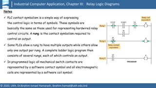
  • 19. Industrial Computer Application, Chapter III: Relay Logic Diagrams © 2020, UKH, Dr.Ibrahim Ismael Hamarash, ibrahim.hamad@ukh.edu.krd Notes ✓ PLC contact symbolism is a simple way of expressing the control logic in terms of symbols. These symbols are basically the same as those used for representing hardwired relay control circuits. A rung is the contact symbolism required to control an output. ✓ Some PLCs allow a rung to have multiple outputs while others allow only one output per rung. A complete ladder logic program then consists of several rungs, each of which controls an output. ✓ In programmed logic all mechanical switch contacts are represented by a software contact symbol and all electromagnetic coils are represented by a software coil symbol.
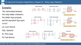
  • 20. Industrial Computer Application, Chapter III: Relay Logic Diagrams © 2020, UKH, Dr.Ibrahim Ismael Hamarash, ibrahim.hamad@ukh.edu.krd Examples: The relationship between the relay ladder schematic, the ladder logic program, and the equivalent logic gate circuit. LS: Limit Switch SOL: Solenoid PL: Pilot Lamp PS: Push Button
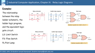
  • 21. Industrial Computer Application, Chapter III: Relay Logic Diagrams © 2020, UKH, Dr.Ibrahim Ismael Hamarash, ibrahim.hamad@ukh.edu.krd Examples: The relationship between the relay ladder schematic, the ladder logic program, and the equivalent logic gate circuit. LS: Limit Switch FS: Flow Switch PL:Pilot Lamp
  • 22. Industrial Computer Application, Chapter III: Relay Logic Diagrams © 2020, UKH, Dr.Ibrahim Ismael Hamarash, ibrahim.hamad@ukh.edu.krd Examples: The relationship between the relay ladder schematic, the ladder logic program, and the equivalent logic gate circuit.
  • 23. Industrial Computer Application, Chapter III: Relay Logic Diagrams © 2020, UKH, Dr.Ibrahim Ismael Hamarash, ibrahim.hamad@ukh.edu.krd Programming Word Level Logic Instructions Most PLCs provide word-level logic instructions as part of their instruction set. The figure illustrates the operation of the AND instruction to perform a word-level AND operation using the bits in the two source addresses. This instruction tells the processor to perform an AND operation on B3:5 and B3:7 and to store the result in destination B3:10 when input device A is true. The destination bits are a result of the logical AND operation.
  • 24. Industrial Computer Application, Chapter III: Relay Logic Diagrams © 2020, UKH, Dr.Ibrahim Ismael Hamarash, ibrahim.hamad@ukh.edu.krd Programming Word Level Logic Instructions The figure illustrates the operation of a word-level OR instruction, which ORs the data in Source A, bit by bit, with the data in Source B and stores the result at the destination address. The address of Source A is B3:1, the address of Source B is B3:2, and the destination address is B3:20. The instruction may be programmed conditionally, with input instruction(s) preceding it, or unconditionally, as shown, without any input instructions preceding it.
  • 25. Industrial Computer Application, Chapter III: Relay Logic Diagrams © 2020, UKH, Dr.Ibrahim Ismael Hamarash, ibrahim.hamad@ukh.edu.krd Selecting the correct word logic instruction for different situations If you want to . . . . . . use this instruction. Know when matching bits in two different words are both ON AND Know when one or both matching bits in two different words are ON OR Know when one or the other bit of matching bits in two different words is ON XOR Reverse the state of bits in a word NOT
  • 26. Industrial Computer Application, Chapter III: Relay Logic Diagrams © 2020, UKH, Dr.Ibrahim Ismael Hamarash, ibrahim.hamad@ukh.edu.krd Reading List Frank Petruzella, Programmable Logic Controllers, McGeaw Hill, 5th Ed., 2017. Austin Scott, Instant PLC Programming with RSLogix 5000, Packt Publishers, 2013. Websites https://www.plcacademy.com http://www.plcs.net
  • 27. Industrial Computer Application, Chapter III: Relay Logic Diagrams © 2020, UKH, Dr.Ibrahim Ismael Hamarash, ibrahim.hamad@ukh.edu.krd Questions?