SlideShare a Scribd company logo
©1996-2009 Operation Technology, Inc. – Workshop Notes: Short-Circuit IEC
Short-Circuit Analysis
IEC Standard
©1996-2009 Operation Technology, Inc. – Workshop Notes: Short-Circuit IEC Slide 2
CORTO CIRCUITO
 Estándar de ANSI/IEEE & IEC.
 Análisis de fallas transitorias
(IEC 61363).
 Efecto de Arco (NFPA 70E-
2000)
 Integrado con coordinación de
dispositivos de protección.
 Evaluación automática de
dispositivos.
Características principales:
©1996-2009 Operation Technology, Inc. – Workshop Notes: Short-Circuit IEC Slide 3
Purpose of Short-Circuit
Studies
• A Short-Circuit Study can be used to determine
any or all of the following:
– Verify protective device close and latch capability
– Verify protective device interrupting capability
– Protect equipment from large mechanical forces
(maximum fault kA)
– I2
t protection for equipment (thermal stress)
– Selecting ratings or settings for relay coordination
Types of Short-Circuit Faults
©1996-2009 Operation Technology, Inc. – Workshop Notes: Short-Circuit IEC Slide 4
©1996-2009 Operation Technology, Inc. – Workshop Notes: Short-Circuit IEC Slide 5
Types of SC Faults
•Three-Phase Ungrounded Fault
•Three-Phase Grounded Fault
•Phase to Phase Ungrounded Fault
•Phase to Phase Grounded Fault
•Phase to Ground Fault
Fault Current
•IL
-G
can range in utility systems from a few percent to
possibly 115 % ( if Xo
< X1
) of I3
-p
h
a
s
e
(85% of all faults).
•In industrial systems the situation IL
-G
> I3
-p
h
a
s
e
is rare.
Typically IL
-G
≅ .87 * I3
-p
h
a
s
e
•In an industrial system, the three-phase fault condition
is frequently the only one considered, since this type of
fault generally results in Maximum current.
Types of Short-Circuit Faults
©1996-2009 Operation Technology, Inc. – Workshop Notes: Short-Circuit IEC Slide 6
)
t
Sin(
Vm
v(t) θ
ω +
∗
=
i(t)
v(t)
Short-Circuit Phenomenon
©1996-2009 Operation Technology, Inc. – Workshop Notes: Short-Circuit IEC Slide 7



 



 



 


 

Offset)
(DC
Transient
State
Steady
t
)
-
sin(
Z
Vm
)
-
t
sin(
Z
Vm
i(t)
(1)
)
t
Sin(
Vm
dt
di
L
Ri
v(t)
L
R
-
e
×
×
+
+
×
=
+
×
=
+
=
φ
θ
φ
θ
ω
θ
ω
expression
following
the
yields
1
equation
Solving
i(t)
v(t)
DC Current
AC Current (Symmetrical) with
No AC Decay
©1996-2009 Operation Technology, Inc. – Workshop Notes: Short-Circuit IEC Slide 8
AC Fault Current Including the
DC Offset (No AC Decay)
©1996-2009 Operation Technology, Inc. – Workshop Notes: Short-Circuit IEC Slide 9
©1996-2009 Operation Technology, Inc. – Workshop Notes: Short-Circuit IEC Slide 10
Machine Reactance ( λ = L I )
AC Decay Current
©1996-2009 Operation Technology, Inc. – Workshop Notes: Short-Circuit IEC Slide 11
Fault Current Including AC & DC Decay
©1996-2009 Operation Technology, Inc. – Workshop Notes: Short-Circuit IEC Slide 12
IEC Short-Circuit
Calculation (IEC 909)
• Initial Symmetrical Short-Circuit Current (I"k)
• Peak Short-Circuit Current (ip)
• Symmetrical Short-Circuit Breaking Current
(Ib)
• Steady-State Short-Circuit Current (Ik)
©1996-2009 Operation Technology, Inc. – Workshop Notes: Short-Circuit IEC Slide 13
IEC Short-Circuit
Calculation Method
• Ik” = Equivalent V @ fault location divided by
equivalent Z
• Equivalent V is based bus nominal kV and c
factor
• XFMR and machine Z adjusted based on
cmax, component Z & operating conditions
©1996-2009 Operation Technology, Inc. – Workshop Notes: Short-Circuit IEC Slide 14
Transformer Z Adjustment
• KT -- Network XFMR
• KS,KSO – Unit XFMR for faults on system side
• KT,S,KT,SO – Unit XFMR for faults in auxiliary
system, not between Gen & XFMR
• K=1– Unit XFMR for faults between Gen &
XFMR
©1996-2009 Operation Technology, Inc. – Workshop Notes: Short-Circuit IEC Slide 15
Syn Machine Z Adjustment
• KG – Synchronous machine w/o unit XFMR
• KS,KSO – With unit XFMR for faults on system
side
• KG,S,KG,SO – With unit XFMR for faults in
auxiliary system, including points between
Gen & XFMR
©1996-2009 Operation Technology, Inc. – Workshop Notes: Short-Circuit IEC Slide 16
Types of Short-Circuits
• Near-To-Generator Short-Circuit
– This is a short-circuit condition to which at least
one synchronous machine contributes a
prospective initial short-circuit current which is
more than twice the generator’s rated current, or
a short-circuit condition to which synchronous
and asynchronous motors contribute more than
5% of the initial symmetrical short-circuit current
( I"k) without motors.
Near-To-Generator Short-Circuit
©1996-2009 Operation Technology, Inc. – Workshop Notes: Short-Circuit IEC Slide 17
©1996-2009 Operation Technology, Inc. – Workshop Notes: Short-Circuit IEC Slide 18
Types of Short-Circuits
• Far-From-Generator Short-Circuit
– This is a short-circuit condition during which the
magnitude of the symmetrical ac component of
available short-circuit current remains essentially
constant.
Far-From-Generator Short-Circuit
©1996-2009 Operation Technology, Inc. – Workshop Notes: Short-Circuit IEC Slide 19
©1996-2009 Operation Technology, Inc. – Workshop Notes: Short-Circuit IEC Slide 20
Factors Used in If Calc
• κ– calc ip based on Ik”
• μ– calc ib for near-to-gen & not meshed network
• q– calc induction machine ib for near-to-gen & not
meshed network
• Equation (75) of Std 60909-0, adjusting Ik for
near-to-gen & meshed network
• λmin & λmax – calc ik
©1996-2009 Operation Technology, Inc. – Workshop Notes: Short-Circuit IEC Slide 21
IEC Short-Circuit Study Case
©1996-2009 Operation Technology, Inc. – Workshop Notes: Short-Circuit IEC Slide 22
Types of Short-Circuits
• Maximum voltage factor is used
• Minimum impedance is used (all negative
tolerances are applied and minimum
resistance temperature is considered)
When these options
are selected
©1996-2009 Operation Technology, Inc. – Workshop Notes: Short-Circuit IEC Slide 23
Types of Short-Circuits
• Minimum voltage factor is used
• Maximum impedance is used (all positive
tolerances are applied and maximum
resistance temperature is considered)
When this option is
selected
©1996-2009 Operation Technology, Inc. – Workshop Notes: Short-Circuit IEC Slide 24
Voltage Factor (c)
• Ratio between equivalent voltage &
nominal voltage
• Required to account for:
• Variations due to time & place
• Transformer taps
• Static loads & capacitances
• Generator & motor subtransient
©1996-2009 Operation Technology, Inc. – Workshop Notes: Short-Circuit IEC Slide 25
Calculation Method
• Breaking kA is more
conservative if the option
No Motor Decay is
selected
IEC SC 909 Calculation
©1996-2009 Operation Technology, Inc. – Workshop Notes: Short-Circuit IEC Slide 26
©1996-2009 Operation Technology, Inc. – Workshop Notes: Short-Circuit IEC Slide 27
Device Duty Comparison
©1996-2009 Operation Technology, Inc. – Workshop Notes: Short-Circuit IEC Slide 28
Mesh & Non-Mesh If
• ETAP automatically determines mesh &
non-meshed contributions according to
individual contributions
• IEC Short Circuit Mesh Determination
Method – 0, 1, or 2 (default)
©1996-2009 Operation Technology, Inc. – Workshop Notes: Short-Circuit IEC Slide 29
L-G Faults
L-G Faults
©1996-2009 Operation Technology, Inc. – Workshop Notes: Short-Circuit IEC Slide 30
Symmetrical Components
L-G Faults
©1996-2009 Operation Technology, Inc. – Workshop Notes: Short-Circuit IEC Slide 31
Sequence Networks
©1996-2009 Operation Technology, Inc. – Workshop Notes: Short-Circuit IEC Slide 32
0
Z
Z
Z
V
3
I
I
3
I
0
2
1
efault
Pr
f
a
f 0
=
+
+
×
=
×
=
g
Z
if
L-G Fault Sequence
Network Connections
©1996-2009 Operation Technology, Inc. – Workshop Notes: Short-Circuit IEC Slide 33
2
1
efault
Pr
f
a
a
Z
Z
V
3
I
I
I 1
2
+
×
=
−
=
L-L Fault Sequence Network
Connections
©1996-2009 Operation Technology, Inc. – Workshop Notes: Short-Circuit IEC Slide 34
0
Z
Z
Z
Z
Z
V
I
I
0
I
I
I
2
0
2
0
1
efault
Pr
f
a
a
a
a 0
1
2
=








+
+
=
=
=
+
+
g
Z
if
L-L-G Fault Sequence
Network Connections
©1996-2009 Operation Technology, Inc. – Workshop Notes: Short-Circuit IEC Slide 35
Transformer Zero Sequence Connections
©1996-2009 Operation Technology, Inc. – Workshop Notes: Short-Circuit IEC Slide 36
grounded.
solidly
are
er
transform
Connected
Y/
or
Generators
if
case
the
be
may
This
I
:
then
true
are
conditions
this
If
&
:
if
greater
be
can
faults
G
-
L
case.
severe
most
the
is
fault
phase
-
3
a
Generally
1
f3
1
0
2
1
∆
<
<
=
φ
φ f
I
Z
Z
Z
Z
Solid Grounded Devices
and L-G Faults
©1996-2009 Operation Technology, Inc. – Workshop Notes: Short-Circuit IEC Slide 37
Zero Sequence Model
• Branch susceptances and static
loads including capacitors will be
considered when this option is
checked
• Recommended by IEC for
systems with isolated neutral,
resonant earthed neutrals &
earthed neutrals with earth fault
factor > 1.4
©1996-2009 Operation Technology, Inc. – Workshop Notes: Short-Circuit IEC Slide 38
Complete reports that include individual
branch contributions for:
•L-G Faults
•L-L-G Faults
•L-L Faults
One-line diagram displayed results that
include:
•L-G/L-L-G/L-L fault current
contributions
•Sequence voltage and currents
•Phase Voltages
Unbalanced Faults Display
& Reports
©1996-2009 Operation Technology, Inc. – Workshop Notes: Short-Circuit IEC Slide 39
Total Fault Current Waveform
Transient Fault Current
Calculation (IEC 61363)
©1996-2009 Operation Technology, Inc. – Workshop Notes: Short-Circuit IEC Slide 40
Percent DC Current Waveform
Transient Fault Current
Calculation (IEC 61363)
©1996-2009 Operation Technology, Inc. – Workshop Notes: Short-Circuit IEC Slide 41
AC Component of Fault Current Waveform
Transient Fault Current
Calculation (IEC 61363)
©1996-2009 Operation Technology, Inc. – Workshop Notes: Short-Circuit IEC Slide 42
Top Envelope of Fault Current Waveform
Transient Fault Current
Calculation (IEC 61363)
©1996-2009 Operation Technology, Inc. – Workshop Notes: Short-Circuit IEC Slide 43
Top Envelope of Fault Current Waveform
Transient Fault Current
Calculation (IEC 61363)
IEC Transient Fault Current
Calculation
©1996-2009 Operation Technology, Inc. – Workshop Notes: Short-Circuit IEC Slide 44
©1996-2009 Operation Technology, Inc. – Workshop Notes: Short-Circuit IEC Slide 45
Complete reports that include individual
branch contributions for:
•L-G Faults
•L-L-G Faults
•L-L Faults
One-line diagram displayed results that
include:
•L-G/L-L-G/L-L fault current
contributions
•Sequence voltage and currents
•Phase Voltages
Unbalanced Faults Display
& Reports
©1996-2009 Operation Technology, Inc. – Workshop Notes: Short-Circuit IEC Slide 46
©1996-2009 Operation Technology, Inc. – Workshop Notes: Short-Circuit IEC Slide 47
©1996-2009 Operation Technology, Inc. – Workshop Notes: Short-Circuit IEC Slide 48
TEMA 2
©1996-2009 Operation Technology, Inc. – Workshop Notes: Short-Circuit IEC
Protective Device Coordination
ETAP Star
©1996-2009 Operation Technology, Inc. – Workshop Notes: Short-Circuit IEC Slide 50
ETAP START PROTECCION Y COORDINACION
 Curvas para más de 75,000
dispositivos.
 Actualización automática de
Corriente de Corto Circuito.
 Coordinación tiempo-corriente de
dispositivos.
 Auto-coordinación de dispositivos.
 Integrados a los diagramas
unifilares.
 Rastreo o cálculos en diferentes
tiempos.
Características principales:
©1996-2009 Operation Technology, Inc. – Workshop Notes: Short-Circuit IEC Slide 51
©1996-2009 Operation Technology, Inc. – Workshop Notes: Short-Circuit IEC Slide 52
Agenda
• Concepts & Applications
• Star Overview
• Features & Capabilities
• Protective Device Type
• TCC Curves
• STAR Short-circuit
• PD Sequence of Operation
• Normalized TCC curves
• Device Libraries
©1996-2009 Operation Technology, Inc. – Workshop Notes: Short-Circuit IEC Slide 53
Definition
• Overcurrent Coordination
– A systematic study of current responsive
devices in an electrical power system.
©1996-2009 Operation Technology, Inc. – Workshop Notes: Short-Circuit IEC Slide 54
Objective
• To determine the ratings and settings of
fuses, breakers, relay, etc.
• To isolate the fault or overloads.
©1996-2009 Operation Technology, Inc. – Workshop Notes: Short-Circuit IEC Slide 55
Criteria
• Economics
• Available Measures of Fault
• Operating Practices
• Previous Experience
©1996-2009 Operation Technology, Inc. – Workshop Notes: Short-Circuit IEC Slide 56
Design
• Open only PD nearest (upstream) of the fault
or overload
• Provide satisfactory protection for overloads
• Interrupt SC as rapidly (instantaneously) as
possible
• Comply with all applicable standards and
codes
• Plot the Time Current Characteristics of
different PDs
©1996-2009 Operation Technology, Inc. – Workshop Notes: Short-Circuit IEC Slide 57
Analysis
When:
• New electrical systems
• Plant electrical system expansion/retrofits
• Coordination failure in an existing plant
©1996-2009 Operation Technology, Inc. – Workshop Notes: Short-Circuit IEC Slide 58
Spectrum Of Currents
• Load Current
– Up to 100% of full-load
– 115-125% (mild overload)
• Overcurrent
– Abnormal loading condition (Locked-Rotor)
• Fault Current
– Fault condition
– Ten times the full-load current and higher
©1996-2009 Operation Technology, Inc. – Workshop Notes: Short-Circuit IEC Slide 59
Protection
• Prevent injury to personnel
• Minimize damage to components
– Quickly isolate the affected portion of the system
– Minimize the magnitude of available short-circuit
©1996-2009 Operation Technology, Inc. – Workshop Notes: Short-Circuit IEC Slide 60
Coordination
• Limit the extent and duration of service
interruption
• Selective fault isolation
• Provide alternate circuits
©1996-2009 Operation Technology, Inc. – Workshop Notes: Short-Circuit IEC Slide 61
Coordination
t
I
C B A
C
D
D B
A
©1996-2009 Operation Technology, Inc. – Workshop Notes: Short-Circuit IEC Slide 62
Protection vs. Coordination
• Coordination is not an exact science
• Compromise between protection and
coordination
– Reliability
– Speed
– Performance
– Economics
– Simplicity
©1996-2009 Operation Technology, Inc. – Workshop Notes: Short-Circuit IEC Slide 63
Required Data
• One-line diagrams (Relay diagrams)
• Power Grid Settings
• Generator Data
• Transformer Data
– Transformer kVA, impedance, and connection
Motor Data
• Load Data
• Fault Currents
• Cable / Conductor Data
• Bus / Switchgear Data
• Instrument Transformer Data (CT, PT)
• Protective Device (PD) Data
– Manufacturer and type of protective devices (PDs)
– One-line diagrams (Relay diagrams)
©1996-2009 Operation Technology, Inc. – Workshop Notes: Short-Circuit IEC Slide 64
Study Procedure
• Prepare an accurate one-line diagram (relay diagrams)
• Obtain the available system current spectrum (operating
load, overloads, fault kA)
• Determine the equipment protection guidelines
• Select the appropriate devices / settings
• Plot the fixed points (damage curves, …)
• Obtain / plot the device characteristics curves
• Analyze the results
©1996-2009 Operation Technology, Inc. – Workshop Notes: Short-Circuit IEC Slide 65
Time Current Characteristics
• TCC Curve / Plot / Graphs
• 4.5 x 5-cycle log-log graph
• X-axis: Current (0.5 – 10,000 amperes)
• Y-axis: Time (.01 – 1000 seconds)
• Current Scaling (…x1, x10, x100, x100…)
• Voltage Scaling (plot kV reference)
• Use ETAP Star Auto-Scale
©1996-2009 Operation Technology, Inc. – Workshop Notes: Short-Circuit IEC Slide 66
©1996-2009 Operation Technology, Inc. – Workshop Notes: Short-Circuit IEC Slide 67
TCC Scaling Example
• Situation:
– A scaling factor of 10 @ 4.16 kV is selected for
TCC curve plots.
• Question
– What are the scaling factors to plot the 0.48 kV
and 13.8 kV TCC curves?
©1996-2009 Operation Technology, Inc. – Workshop Notes: Short-Circuit IEC Slide 68
TCC Scaling Example
• Solution
©1996-2009 Operation Technology, Inc. – Workshop Notes: Short-Circuit IEC Slide 69
Fixed Points
• Cable damage curves
• Cable ampacities
• Transformer damage curves & inrush points
• Motor starting curves
• Generator damage curve / Decrement curve
• SC maximum fault points
Points or curves which do not change regardless
of protective device settings:
©1996-2009 Operation Technology, Inc. – Workshop Notes: Short-Circuit IEC Slide 70
Capability / Damage Curves
t
I
I2
2
t
Gen
I2
t
Motor
Xfmr
I2
t
Cable
I2
t
©1996-2009 Operation Technology, Inc. – Workshop Notes: Short-Circuit IEC Slide 71
Cable Protection
• Standards & References
– IEEE Std 835-1994 IEEE Standard Power Cable Ampacity
Tables
– IEEE Std 848-1996 IEEE Standard Procedure for the
Determination of the Ampacity Derating of Fire-Protected
Cables
– IEEE Std 738-1993 IEEE Standard for Calculating the
Current- Temperature Relationship of Bare Overhead
Conductors
– The Okonite Company Engineering Data for Copper and
Aluminum Conductor Electrical Cables, Bulletin EHB-98
©1996-2009 Operation Technology, Inc. – Workshop Notes: Short-Circuit IEC Slide 72
Cable Protection
2
2
1
t
A
T 234
0.0297log
T 234
Ι
=
 
+
 
+
 
The actual temperature rise of a cable when exposed to
a short circuit current for a known time is calculated by:
Where:
A= Conductor area in circular-mils
I = Short circuit current in amps
t = Time of short circuit in seconds
T1
= Initial operation temperature (750
C)
T2
=Maximum short circuit temperature
(1500
C)
©1996-2009 Operation Technology, Inc. – Workshop Notes: Short-Circuit IEC Slide 73
Cable Short-Circuit Heating Limits
Recommended
temperature rise:
B) CU 75-200C
©1996-2009 Operation Technology, Inc. – Workshop Notes: Short-Circuit IEC Slide 74
Shielded
Cable
The normal tape
width is 1½
inches
©1996-2009 Operation Technology, Inc. – Workshop Notes: Short-Circuit IEC Slide 75
NEC Section 110 14 C
‑
• (c) Temperature limitations. The temperature rating associated with the
ampacity of a conductor shall be so selected and coordinated as to not exceed
the lowest temperature rating of any
lowest temperature rating of any connected termination
connected termination, conductor, or
device. Conductors with temperature ratings higher than specified for
terminations shall be permitted to be used for ampacity adjustment, correction,
or both.
• (1) Termination provisions of equipment for circuits rated 100 amperes or less,
or marked for Nos. 14 through 1 conductors, shall be used only for conductors
rated 600C (1400F).
• Exception No. 1: Conductors with higher temperature ratings shall be permitted
to be used, provided the ampacity of such conductors is determined based on
the 6O0C (1400F) ampacity of the conductor size used.
• Exception No. 2: Equipment termination provisions shall be permitted to be
used with higher rated conductors at the ampacity of the higher rated
conductors, provided the equipment is listed and identified for use with the
higher rated conductors.
• (2) Termination provisions of equipment for circuits rated over 100 amperes, or
marked for conductors larger than No. 1, shall be used only with conductors
rated 750C (1670F).
©1996-2009 Operation Technology, Inc. – Workshop Notes: Short-Circuit IEC Slide 76
Transformer Protection
• Standards & References
– National Electric Code 2002 Edition
– C37.91-2000; IEEE Guide for Protective Relay Applications to Power
Transformers
– C57.12.59; IEEE Guide for Dry-Type Transformer Through-Fault Current
Duration.
– C57.109-1985; IEEE Guide for Liquid-Immersed Transformer Through-
Fault-Current Duration
– APPLIED PROCTIVE RELAYING; J.L. Blackburn; Westinghouse Electric
Corp; 1976
– PROTECTIVE RELAYING, PRINCIPLES AND APPLICATIONS; J.L.
Blackburn; Marcel Dekker, Inc; 1987
– IEEE Std 242-1986; IEEE Recommended Practice for Protection and
Coordination of Industrial and Commercial Power Systems
–
©1996-2009 Operation Technology, Inc. – Workshop Notes: Short-Circuit IEC Slide 77
Transformer Category
ANSI/IEEE C-57.109
©1996-2009 Operation Technology, Inc. – Workshop Notes: Short-Circuit IEC Slide 78
Transformer Categories I, II
©1996-2009 Operation Technology, Inc. – Workshop Notes: Short-Circuit IEC Slide 79
Transformer Categories III
©1996-2009 Operation Technology, Inc. – Workshop Notes: Short-Circuit IEC Slide 80
Transformer
t
(sec)
I (pu)
Thermal
200
2.5
I
2
t = 1250
2
25
Isc
Mechanical
K=(1/Z)
2
t
(D-D LL) 0.87
(D-R LG) 0.58
Frequent Fault
Infrequent Fault
Inrush
FLA
©1996-2009 Operation Technology, Inc. – Workshop Notes: Short-Circuit IEC Slide 81
©1996-2009 Operation Technology, Inc. – Workshop Notes: Short-Circuit IEC Slide 82
Transformer Protection
M
Any Location – Non-Supervised
©1996-2009 Operation Technology, Inc. – Workshop Notes: Short-Circuit IEC Slide 83
Transformer Protection
• Turn on or inrush current
• Internal transformer faults
• External or through faults of major
magnitude
• Repeated large motor starts on the
transformer. The motor represents a
major portion or the transformers KVA
rating.
• Harmonics
• Over current protection – Device 50/51
• Ground current protection – Device
50/51G
• Differential – Device 87
• Over or under excitation – volts/ Hz –
Device 24
• Sudden tank pressure – Device 63
• Dissolved gas detection
• Oil Level
• Fans
• Oil Pumps
• Pilot wire – Device 85
• Fault withstand
• Thermal protection – hot spot, top of oil
temperature, winding temperature
• Devices 26 & 49
• Reverse over current – Device 67
• Gas accumulation – Buckholz relay
• Over voltage –Device 59
• Voltage or current balance – Device 60
• Tertiary Winding Protection if supplied
• Relay Failure Scheme
• Breaker Failure Scheme
©1996-2009 Operation Technology, Inc. – Workshop Notes: Short-Circuit IEC Slide 84
Recommended Minimum
Transformer Protection
Protective system Winding and/or power system
grounded neutral grounded
Winding and/or power system
neutral ungrounded
Up to 10 MVA
Above 10 MVA
Up to 10 MVA Above
10 MVA
Differential -
√ -
√
Time over current √ √ √ √
Instantaneous restricted
ground fault
√ √ - -
Time delayed ground
fault
√ √ - -
Gas detection
√ -
√
Over excitation -
√ √ √
Overheating -
√ -
√
©1996-2009 Operation Technology, Inc. – Workshop Notes: Short-Circuit IEC Slide 85
Question
What is ANSI Shift Curve?
©1996-2009 Operation Technology, Inc. – Workshop Notes: Short-Circuit IEC Slide 86
Answer
• For delta-delta connected transformers, with
line-to-line faults on the secondary side, the
curve must be reduced to 87% (shift to the
left by a factor of 0.87)
• For delta-wye connection, with single line-to-
ground faults on the secondary side, the
curve values must be reduced to 58% (shift
to the left by a factor of 0.58)
©1996-2009 Operation Technology, Inc. – Workshop Notes: Short-Circuit IEC Slide 87
Question
What is meant by Frequent and
Infrequent for transformers?
©1996-2009 Operation Technology, Inc. – Workshop Notes: Short-Circuit IEC Slide 88
Infrequent Fault Incidence Zones for Category II & III Transformers
* Should be selected by reference to the frequent -fault-incidence protection curve or for
transformers serving industrial, commercial and institutional power systems with secondary -side
conductors enclosed in conduit, bus duct, etc., the feeder protective device may be selected by
reference to the infrequent -fault-incidence protection curve.
Source: IEEE C57
Source
Transformer primary -side protective device
(fuses, relayed circuit breakers, etc.) may be
selected by reference to the infrequent -fault-
incidence protection curve
Category II or III Transformer
Fault will be cleared by transformer
primary -side protective device
Optional main secondary –side protective device.
May be selected by reference to the infrequent -fault-
incidence protection curve
Feeder protective device
Fault will be cleared by transformer primary -side
protective device or by optional main secondary -
side protection device
Fault will be cleared by
feeder protective device
Infrequent -Fault
Incidence Zone*
Feeders
Frequent -Fault
Inciden ce Zone*
©1996-2009 Operation Technology, Inc. – Workshop Notes: Short-Circuit IEC Slide 89
Motor Protection
• Standards & References
– IEEE Std 620-1996 IEEE Guide for the Presentation of
Thermal Limit Curves for Squirrel Cage Induction
Machines.
– IEEE Std 1255-2000 IEEE Guide for Evaluation of
Torque Pulsations During Starting of Synchronous Motors
– ANSI/ IEEE C37.96-2000 Guide for AC Motor Protection
– The Art of Protective Relaying – General Electric
©1996-2009 Operation Technology, Inc. – Workshop Notes: Short-Circuit IEC Slide 90
Motor Protection
• Motor Starting Curve
• Thermal Protection
• Locked Rotor Protection
• Fault Protection
©1996-2009 Operation Technology, Inc. – Workshop Notes: Short-Circuit IEC Slide 91
Motor Overload Protection
(NEC Art 430-32 – Continuous-Duty Motors)
• Thermal O/L (Device 49)
• Motors with SF not less than 1.15
– 125% of FLA
• Motors with temp. rise not over 40°C
– 125% of FLA
• All other motors
– 115% of FLA
©1996-2009 Operation Technology, Inc. – Workshop Notes: Short-Circuit IEC Slide 92
Motor Protection – Inst. Pickup
LOCKED
ROTOR S d
1
I
X X "
=
+
PICK UP
LOCKED ROTOR
I
RELAY PICK UP 1.2 TO 1.2
I
= ∗
PICK UP
LOCKED ROTOR
I
RELAY PICK UP 1.6 TO 2
I
= ∗
with a time delay of 0.10 s (six cycles at 60 Hz)
Recommended Instantaneous Setting:
If the recommended setting criteria cannot be met, or where more sensitive
protection is desired, the in-stantaneous relay (or a second relay) can be set more
sensitively if delayed by a timer. This permits the asymmetrical
asymmetrical starting component
to decay out. A typical setting for this is:
©1996-2009 Operation Technology, Inc. – Workshop Notes: Short-Circuit IEC Slide 93
Locked Rotor Protection
• Thermal Locked Rotor (Device 51)
• Starting Time (TS < TLR)
• LRA
– LRA sym
– LRA asym (1.5-1.6 x LRA sym) + 10% margin
©1996-2009 Operation Technology, Inc. – Workshop Notes: Short-Circuit IEC Slide 94
Fault Protection
(NEC Art / Table 430-52)
• Non-Time Delay Fuses
– 300% of FLA
• Dual Element (Time-Delay Fuses)
– 175% of FLA
• Instantaneous Trip Breaker
– 800% - 1300% of FLA*
• Inverse Time Breakers
– 250% of FLA
*can be set up to 1700% for Design B (energy efficient) Motor
©1996-2009 Operation Technology, Inc. – Workshop Notes: Short-Circuit IEC Slide 95
Low Voltage Motor Protection
• Usually pre-engineered (selected from
Catalogs)
• Typically, motors larger than 2 Hp are
protected by combination starters
• Overload / Short-circuit protection
©1996-2009 Operation Technology, Inc. – Workshop Notes: Short-Circuit IEC Slide 96
Low-voltage Motor
Ratings Range of ratings
Continuous amperes 9-250 —
Nominal voltage (V) 240-600 —
Horsepower 1.5-1000 —
Starter size (NEMA) — 00-9
Types of protection Quantity NEMA designation
Overload: overload relay
elements
3 OL
Short circuit:
circuit breaker current
trip elements
3 CB
Fuses 3 FU
Undervoltage: inherent
with integral control
supply and three-wire
control circuit
— —
Ground fault (when
speci-fied): ground relay
with toroidal CT
— —
©1996-2009 Operation Technology, Inc. – Workshop Notes: Short-Circuit IEC Slide 97
Minimum Required Sizes of a NEMA
Combination Motor Starter System
R
HP
C
FLC
TER
E
UM
©1996-2009 Operation Technology, Inc. – Workshop Notes: Short-Circuit IEC Slide 98
Required Data - Protection of a
Medium Voltage Motor
• Rated full load current
• Service factor
• Locked rotor current
• Maximum locked rotor time (thermal limit curve) with the motor at ambient and/or
operating temperature
• Minimum no load current
• Starting power factor
• Running power factor
• Motor and connected load accelerating time
• System phase rotation and nominal frequency
• Type and location of resistance temperature devices (RTDs), if used
• Expected fault current magnitudes
• First ½ cycle current
• Maximum motor starts per hour
©1996-2009 Operation Technology, Inc. – Workshop Notes: Short-Circuit IEC Slide 99
Medium-Voltage Class E Motor Controller
Ratings Class El
(without
fuses)
Class E2 (with
fuses)
Nominal system voltage 2300-6900 2300-6900
Horsepower 0-8000 0-8000
Symmetrical MVA interrupting
capacity at nominal
system voltage
25-75 160-570
Types of Protective Devices Quantity NEMA Designation
Overload, or locked Rotor, or
both:
Thermal overload relay
TOC relay
IOC relay plus time delay
3
3
3
OL OC TR/O
Thermal overload relay 3 OL
TOC relay 3 OC
IOC relay plus time delay 3 TR/OC
Short Circuit:
Fuses, Class E2 3 FU
IOC relay, Class E1 3 OC
Ground Fault
TOC residual relay 1 GP
Overcurrent relay with
toroidal CT
1 GP
NEMA Class E2 medium
voltage starter
NEMA Class E1
medium voltage starter
Phase Balance
Current balance relay 1 BC
Negative-sequence voltage
relay (per bus), or both
1 —
Undervoltage:
Inherent with integral
control supply and three-
wire control circuit, when
voltage falls suffi-ciently to
permit the contractor to
open and break the seal-in
circuit
— UV
Temperature:
Temperature relay,
operating from resistance
sensor or ther-mocouple in
stator winding
— OL
©1996-2009 Operation Technology, Inc. – Workshop Notes: Short-Circuit IEC Slide 100
Starting Current of a 4000Hp, 12 kV,
1800 rpm Motor
First half cycle current showing
current offset.
Beginning of run up current
showing load torque pulsations.
©1996-2009 Operation Technology, Inc. – Workshop Notes: Short-Circuit IEC Slide 101
Starting Current of a 4000Hp, 12 kV,
1800 rpm Motor -
Motor pull in current showing motor
reaching synchronous speed
Oscillographs
©1996-2009 Operation Technology, Inc. – Workshop Notes: Short-Circuit IEC Slide 102
Thermal Limit Curve
©1996-2009 Operation Technology, Inc. – Workshop Notes: Short-Circuit IEC Slide 103
Thermal Limit Curve
Typical
Curve
©1996-2009 Operation Technology, Inc. – Workshop Notes: Short-Circuit IEC Slide 104
200 HP
MCP
O/L
Starting Curve
I2
T
(49)
MCP (50)
(51)
ts
tL
R
LRAs LRAasy
m
©1996-2009 Operation Technology, Inc. – Workshop Notes: Short-Circuit IEC Slide 105
Protective Devices
• Fuse
• Overload Heater
• Thermal Magnetic
• Low Voltage Solid State Trip
• Electro-Mechanical
• Motor Circuit Protector (MCP)
• Relay (50/51 P, N, G, SG, 51V, 67, 49, 46, 79, 21, …)
©1996-2009 Operation Technology, Inc. – Workshop Notes: Short-Circuit IEC Slide 106
Fuse (Power Fuse)
• Non Adjustable Device (unless electronic)
• Continuous and Interrupting Rating
• Voltage Levels (Max kV)
• Interrupting Rating (sym, asym)
• Characteristic Curves
– Min. Melting
– Total Clearing
• Application (rating type: R, E, X, …)
©1996-2009 Operation Technology, Inc. – Workshop Notes: Short-Circuit IEC Slide 107
Fuse Types
• Expulsion Fuse (Non-CLF)
• Current Limiting Fuse (CLF)
• Electronic Fuse (S&C Fault Fiter)
©1996-2009 Operation Technology, Inc. – Workshop Notes: Short-Circuit IEC Slide 108
Minimum Melting
Time Curve
Total Clearing
Time Curve
©1996-2009 Operation Technology, Inc. – Workshop Notes: Short-Circuit IEC Slide 109
Current Limiting Fuse
(CLF)
• Limits the peak current of short-circuit
• Reduces magnetic stresses (mechanical
damage)
• Reduces thermal energy
©1996-2009 Operation Technology, Inc. – Workshop Notes: Short-Circuit IEC Slide 110
Current Limiting Action
Current
(peak
amps)
tm ta
Ip
’
Ip
tc
ta = tc – tm
ta = Arcing Time
tm = Melting Time
tc = Clearing Time
Ip = Peak Current
Ip
’ = Peak Let-thru Current
Time (cycles)
©1996-2009 Operation Technology, Inc. – Workshop Notes: Short-Circuit IEC Slide 111
© 1996-2009 Operation Technology, Inc. – Workshop Notes: Protective Device Coordination
©1996-2009 Operation Technology, Inc. – Workshop Notes: Short-Circuit IEC Slide 112
Symmetrical RMS Amperes
Peak
Let-Through
Amperes
100 A
60 A
7% PF (X/R = 14.3)
12,500
5,200
230,000
300 A
100,000
Let-Through Chart
©1996-2009 Operation Technology, Inc. – Workshop Notes: Short-Circuit IEC Slide 113
Fuse
Generally:
• CLF is a better short-circuit protection
• Non-CLF (expulsion fuse) is a better
Overload protection
• Electronic fuses are typically easier to
coordinate due to the electronic control
adjustments
©1996-2009 Operation Technology, Inc. – Workshop Notes: Short-Circuit IEC Slide 114
Selectivity Criteria
Typically:
• Non-CLF: 140% of full load
• CLF: 150% of full load
• Safety Margin: 10% applied to Min
Melting (consult the fuse manufacturer)
©1996-2009 Operation Technology, Inc. – Workshop Notes: Short-Circuit IEC Slide 115
Molded Case CB
• Thermal-Magnetic
• Magnetic Only
• Motor Circuit Protector
(MCP)
• Integrally Fused (Limiters)
• Current Limiting
• High Interrupting Capacity
• Non-Interchangeable Parts
• Insulated Case (Interchange
Parts)
Types
• Frame Size
• Poles
• Trip Rating
• Interrupting Capability
• Voltage
©1996-2009 Operation Technology, Inc. – Workshop Notes: Short-Circuit IEC Slide 116
MCCB
©1996-2009 Operation Technology, Inc. – Workshop Notes: Short-Circuit IEC Slide 117
MCCB with SST Device
©1996-2009 Operation Technology, Inc. – Workshop Notes: Short-Circuit IEC Slide 118
Thermal Minimum
Thermal Maximum
Magnetic
(instantaneous)
©1996-2009 Operation Technology, Inc. – Workshop Notes: Short-Circuit IEC Slide 119
LVPCB
• Voltage and Frequency Ratings
• Continuous Current / Frame Size / Sensor
• Interrupting Rating
• Short-Time Rating (30 cycle)
• Fairly Simple to Coordinate
• Phase / Ground Settings
• Inst. Override
©1996-2009 Operation Technology, Inc. – Workshop Notes: Short-Circuit IEC Slide 120
CB 2
CB 1
IT
ST PU
ST Band
LT PU
LT Band
480 kV
CB 2
CB 1
If =30 kA
©1996-2009 Operation Technology, Inc. – Workshop Notes: Short-Circuit IEC Slide 121
Inst. Override
©1996-2009 Operation Technology, Inc. – Workshop Notes: Short-Circuit IEC Slide 122
Overload Relay / Heater
• Motor overload protection is provided by a
device that models the temperature rise of
the winding
• When the temperature rise reaches a point
that will damage the motor, the motor is de-
energized
• Overload relays are either bimetallic, melting
alloy or electronic
©1996-2009 Operation Technology, Inc. – Workshop Notes: Short-Circuit IEC Slide 123
Overload Heater (Mfr. Data)
©1996-2009 Operation Technology, Inc. – Workshop Notes: Short-Circuit IEC Slide 124
Question
What is Class 10 and Class 20 Thermal
OLR curves?
©1996-2009 Operation Technology, Inc. – Workshop Notes: Short-Circuit IEC Slide 125
Answer
• At 600% Current Rating:
– Class 10 for fast trip, 10
seconds or less
– Class 20 for, 20 seconds or
less (commonly used)
– There is also Class 15, 30
for long trip time (typically
provided with electronic
overload relays)
6
20
©1996-2009 Operation Technology, Inc. – Workshop Notes: Short-Circuit IEC Slide 126
Answer
©1996-2009 Operation Technology, Inc. – Workshop Notes: Short-Circuit IEC Slide 127
Overload Relay / Heater
• When the temperature at the combination motor starter is more than
±10 °C (±18 °F) different than the temperature at the motor, ambient
temperature correction of the motor current is required.
• An adjustment is required because the output that a motor can safely
deliver varies with temperature.
• The motor can deliver its full rated horsepower at an ambient
temperature specified by the motor manufacturers, normally + 40 °C.
At high temperatures (higher than + 40 °C) less than 100% of the
normal rated current can be drawn from the motor without shortening
the insulation life.
• At lower temperatures (less than + 40 °C) more than 100% of the
normal rated current could be drawn from the motor without shortening
the insulation life.
©1996-2009 Operation Technology, Inc. – Workshop Notes: Short-Circuit IEC Slide 128
Overcurrent Relay
• Time-Delay (51 – I>)
• Short-Time Instantaneous ( I>>)
• Instantaneous (50 – I>>>)
• Electromagnetic (induction Disc)
• Solid State (Multi Function / Multi Level)
• Application
©1996-2009 Operation Technology, Inc. – Workshop Notes: Short-Circuit IEC Slide 129
© 1996-2009 Operation Technology, Inc. – Workshop Notes: Protective Device Coordination
©1996-2009 Operation Technology, Inc. – Workshop Notes: Short-Circuit IEC Slide 130
Time-Overcurrent Unit
• Ampere Tap Calculation
– Ampere Pickup (P.U.) = CT Ratio x A.T. Setting
– Relay Current (IR) = Actual Line Current (IL) / CT
Ratio
– Multiples of A.T. = IR/A.T. Setting
= IL/(CT Ratio x A.T.
Setting)
IL
IR
CT
51
©1996-2009 Operation Technology, Inc. – Workshop Notes: Short-Circuit IEC Slide 131
Instantaneous Unit
• Instantaneous Calculation
– Ampere Pickup (P.U.) = CT Ratio x IT Setting
– Relay Current (IR) = Actual Line Current (IL) / CT
Ratio
– Multiples of IT = IR/IT Setting
= IL/(CT Ratio x IT Setting)
IL
IR
CT
50
©1996-2009 Operation Technology, Inc. – Workshop Notes: Short-Circuit IEC Slide 132
Relay Coordination
• Time margins should be maintained between T/C
curves
• Adjustment should be made for CB opening time
• Shorter time intervals may be used for solid state
relays
• Upstream relay should have the same inverse T/C
characteristic as the downstream relay (CO-8 to
CO-8) or be less inverse (CO-8 upstream to CO-6
downstream)
• Extremely inverse relays coordinates very well with
CLFs
©1996-2009 Operation Technology, Inc. – Workshop Notes: Short-Circuit IEC Slide 133
Situation
Calculate Relay Setting (Tap, Inst. Tap & Time Dial)
For This System
4.16 kV
DS 5 MVA
Cable
1-3/C 500 kcmil
CU - EPR
CB
Isc = 30,000 A
6 %
50/51 Relay: IFC 53
CT 800:5
©1996-2009 Operation Technology, Inc. – Workshop Notes: Short-Circuit IEC Slide 134
Solution
A
Inrsuh 328
,
8
694
12
I =
×
=
A
338
.
4
800
5
I
I L
R =
×
=
Transformer: A
kV
kVA
L 694
16
.
4
3
000
,
5
I =
×
=
IL
CT
R
IR
Set Relay:
A
55
1
.
52
800
5
328
,
8
)
50
(
1
)
38
.
1
(6/4.338
0
.
6
4
.
5
338
.
4
%
125
= >
=
×
=
=
=
=
×
=
A
Inst
TD
A
TAP
A
©1996-2009 Operation Technology, Inc. – Workshop Notes: Short-Circuit IEC Slide 135
Question
What T/C Coordination interval should be maintained between relays?
©1996-2009 Operation Technology, Inc. – Workshop Notes: Short-Circuit IEC Slide 136
Answer
A
t
I
B
CB Opening Time
+
Induction Disc Overtravel (0.1 sec)
+
Safety margin (0.2 sec w/o Inst. & 0.1 sec w/ Inst.)
©1996-2009 Operation Technology, Inc. – Workshop Notes: Short-Circuit IEC Slide 137
Recloser
• Recloser protects electrical transmission systems from temporary
voltage surges and other unfavorable conditions.
• Reclosers can automatically "reclose" the circuit and restore normal
power transmission once the problem is cleared.
• Reclosers are usually designed with failsafe mechanisms that prevent
them from reclosing if the same fault occurs several times in
succession over a short period. This insures that repetitive line faults
don't cause power to switch on and off repeatedly, since this could
cause damage or accelerated wear to electrical equipment.
• It also insures that temporary faults such as lightning strikes or
transmission switching don't cause lengthy interruptions in service.
©1996-2009 Operation Technology, Inc. – Workshop Notes: Short-Circuit IEC Slide 138
Recloser Types
• Hydraulic
• Electronic
– Static Controller
– Microprocessor Controller
©1996-2009 Operation Technology, Inc. – Workshop Notes: Short-Circuit IEC Slide 139
Recloser Curves
©1996-2009 Operation Technology, Inc. – Workshop Notes: Short-Circuit IEC Slide 140
TEMA 3
©1996-2009 Operation Technology, Inc. – Workshop Notes: Short-Circuit IEC
Transient Stability
©1996-2009 Operation Technology, Inc. – Workshop Notes: Short-Circuit IEC Slide 142
Topics
• What is Transient Stability (TS)
• What Causes System Unstable
• Effects When System Is Instable
• Transient Stability Definition
• Modeling and Data Preparation
• ETAP TS Study Outputs
• Power System TS Studies
• Solutions to Stability Problems
©1996-2009 Operation Technology, Inc. – Workshop Notes: Short-Circuit IEC Slide 143
What is Transient Stability
• TS is also called Rotor Angle Stability
Something between mechanical system and
electrical system – energy conversion
• It is a Electromechanical Phenomenon
Time frame in milliseconds
• All Synchronous Machines Must Remain in
Synchronism with One Another
Synchronous generators and motors
This is what system stable or unstable means
©1996-2009 Operation Technology, Inc. – Workshop Notes: Short-Circuit IEC Slide 144
What is Transient Stability
• Torque Equation (generator case)
T = mechanical torque
P = number of poles
φ a
ir = air-gap flux
Fr = rotor field MMF
δ = rotor angle
©1996-2009 Operation Technology, Inc. – Workshop Notes: Short-Circuit IEC Slide 145
What is Transient Stability
• Swing Equation
M = inertia constant
D = damping constant
Pm
e
c
h = input mechanical power
Pe
le
c = output electrical power
©1996-2009 Operation Technology, Inc. – Workshop Notes: Short-Circuit IEC Slide 146
What Causes System Unstable
• From Torque Equation
T (prime mover)
Rotor MMF (field winding)
Air-Gap Flux (electrical system)
• From Swing Equation
Pmech
Pelec
Different time constants in mechanical and
electrical systems
©1996-2009 Operation Technology, Inc. – Workshop Notes: Short-Circuit IEC Slide 147
What Causes System Unstable
• In real operation
Short-circuit
Loss of excitation
Prime mover failure
Loss of utility connections
Loss of a portion of in-plant generation
Starting of a large motor
Switching operations
Impact loading on motors
Sudden large change in load and generation
©1996-2009 Operation Technology, Inc. – Workshop Notes: Short-Circuit IEC Slide 148
Effects When System Is Instable
Case 1: Steady-state stable
Case 2: Transient stable
Case 3: Small-signal unstable
Case 4: First swing unstable
• Swing in Rotor Angle (as well as in V, I, P,
Q and f)
©1996-2009 Operation Technology, Inc. – Workshop Notes: Short-Circuit IEC Slide 149
Effects When System Is Instable
• A 2-Machine
Example
• At δ = -180º
(Out-of-Step,
Slip the Pole)
©1996-2009 Operation Technology, Inc. – Workshop Notes: Short-Circuit IEC Slide 150
Effects When System Is Instable
• Synchronous machine slip poles –
generator tripping
• Power swing
• Misoperation of protective devices
• Interruption of critical loads
• Low-voltage conditions – motor drop-offs
• Damage to equipment
• Area wide blackout
• …
©1996-2009 Operation Technology, Inc. – Workshop Notes: Short-Circuit IEC Slide 151
• Examine One Generator
• Power Output Capability Curve
∀ δ is limited to 180º
Transient Stability Definition
©1996-2009 Operation Technology, Inc. – Workshop Notes: Short-Circuit IEC Slide 152
Transient Stability Definition
• Transient and Dynamic Stability Limit
 After a severe disturbance, the synchronous
generator reaches a steady-state operating
condition without a prolonged loss of
synchronism
 Limit: δ < 180°during swing
©1996-2009 Operation Technology, Inc. – Workshop Notes: Short-Circuit IEC Slide 153
• Synchronous Machine
 Machine
 Exciter and AVR
 Prime Mover and Governor / Load Torque
 Power System Stabilizer (PSS) (Generator)
Modeling and Data Preparation
©1996-2009 Operation Technology, Inc. – Workshop Notes: Short-Circuit IEC Slide 154
Modeling and Data Preparation
©1996-2009 Operation Technology, Inc. – Workshop Notes: Short-Circuit IEC Slide 155
Modeling and Data Preparation
• Typical synchronous machine data
©1996-2009 Operation Technology, Inc. – Workshop Notes: Short-Circuit IEC Slide 156
Modeling and Data Preparation
• Induction Machine
 Machine
 Load Torque
©1996-2009 Operation Technology, Inc. – Workshop Notes: Short-Circuit IEC Slide 157
Modeling and Data Preparation
• Power Grid
 Short-Circuit Capability
 Fixed internal voltage and infinite inertia
©1996-2009 Operation Technology, Inc. – Workshop Notes: Short-Circuit IEC Slide 158
Modeling and Data Preparation
• Load
 Voltage dependency
 Frequency dependency
©1996-2009 Operation Technology, Inc. – Workshop Notes: Short-Circuit IEC Slide 159
Modeling and Data Preparation
• Load
©1996-2009 Operation Technology, Inc. – Workshop Notes: Short-Circuit IEC Slide 160
Modeling and Data Preparation
• Events and Actions
©1996-2009 Operation Technology, Inc. – Workshop Notes: Short-Circuit IEC Slide 161
Modeling and Data Preparation
Device Type Action
Bus 3-P Fault L-G Fault Clear Fault
Branch Fraction Fault Clear Fault
PD Trip Close
Generator Droop / Isoch Start Loss Exc. P Change V Change Delete
Grid P Change V Change Delete
Motor Accelerate Load
Change
Delete
Lumped Load Load Change Delete
MOV Start
Wind Turbine Disturbance Gust Ramp
MG Set Emergency Main
©1996-2009 Operation Technology, Inc. – Workshop Notes: Short-Circuit IEC Slide 162
Power System TS Studies
• Fault
3-phase and single phase fault
Clear fault
Critical Fault Clearing Time (CFCT)
Critical System Separation Time (CSST)
• Bus Transfer
Fast load transferring
• Load Shedding
Under-frequency
Under-voltage
• Motor Dynamic Acceleration
Induction motor
Synchronous motor
©1996-2009 Operation Technology, Inc. – Workshop Notes: Short-Circuit IEC Slide 163
Power System TS Studies
• Critical Fault Clearing Time (CFCT)
• Critical Separation Time (CSST)
unstable
unstable
Cycle
Clear fault
Clear fault
1 cycle
unstable
stable 1 cycle
Clear fault
Clear fault
CFCT
Fault
unstable
unstable
Cycle
1 cycle
unstable
stable
1 cycle
CSST
Separation
Separation
Separation
Separation
Fault
©1996-2009 Operation Technology, Inc. – Workshop Notes: Short-Circuit IEC Slide 164
Power System TS Studies
-1
-0.8
-0.6
-0.4
-0.2
0
0.2
0.4
0.6
0.8
1
-1 -0.8 -0.6 -0.4 -0.2 0 0.2 0.4 0.6 0.8 1
Vmotor
s
• Fast Bus Transfer
Motor residual voltage
©1996-2009 Operation Technology, Inc. – Workshop Notes: Short-Circuit IEC Slide 165
• Fast Bus Transfer
Ttra
n
s
fe
r ≤ 10 cycles
δ ≤ 90 degrees
ER ≤ 1.33 per unit (133%)
Power System TS Studies
ES = System equivalent per unit
volts per hertz
EM = Motor residual per unit per
hertz
ER = Resultant vectorial voltage
in per unit volts per hertz
δ
©1996-2009 Operation Technology, Inc. – Workshop Notes: Short-Circuit IEC Slide 166
Power System TS Studies
• Load Shedding
©1996-2009 Operation Technology, Inc. – Workshop Notes: Short-Circuit IEC Slide 167
Power System TS Studies
• Motor Dynamic Acceleration
Important for islanded system operation
Motor starting impact
Generator AVR action
Reacceleration
©1996-2009 Operation Technology, Inc. – Workshop Notes: Short-Circuit IEC Slide 168
• Improve System Design
 Increase synchronizing power
• Design and Selection of Rotating
Equipment
 Use of induction machines
 Increase moment of inertia
 Reduce transient reactance
 Improve voltage regulator and exciter
characteristics
Solution to Stability Problems
©1996-2009 Operation Technology, Inc. – Workshop Notes: Short-Circuit IEC Slide 169
• Application of Power System Stabilizer
(PSS)
• Add System Protections
 Fast fault clearance
 Load shedding
 System separation
Out-Of-Step relay
…
Solution to Stability Problems
©1996-2009 Operation Technology, Inc. – Workshop Notes: Short-Circuit IEC
©1996-2009 Operation Technology, Inc. – Workshop Notes: Short-Circuit IEC Slide 171
TEMA 4
©1996-2009 Operation Technology, Inc. – Workshop Notes: Short-Circuit IEC
Harmonic Analysis
©1996-2009 Operation Technology, Inc. – Workshop Notes: Short-Circuit IEC Slide 173
ARMONICAS
 Exploración de frecuencia.
 Flujo Armónico de Carga.
 Dimensionamiento y Diseño de
Filtros.
 Evaluación Automática del límite
de distorsión.
 Factores de la influencia del
teléfono (TIF & I*T)
Características principales:
©1996-2009 Operation Technology, Inc. – Workshop Notes: Short-Circuit IEC Slide 174
©1996-2009 Operation Technology, Inc. – Workshop Notes: Short-Circuit IEC Slide 175
Types of Power Quality
Problems
©1996-2009 Operation Technology, Inc. – Workshop Notes: Short-Circuit IEC Slide 176
Waveform Distortion
• Primary Types of Waveform Distortion
– DC Offset
– Harmonics
– Interharmonics
– Notching
– Noise
©1996-2009 Operation Technology, Inc. – Workshop Notes: Short-Circuit IEC Slide 177
Harmonics
• One special category of power quality
problems
• “Harmonics are voltages and/or currents
present in an electrical system at some
multiple of the fundamental frequency.”
(IEEE Std 399, Brown Book)
©1996-2009 Operation Technology, Inc. – Workshop Notes: Short-Circuit IEC Slide 178
Nonlinear Loads
• Sinusoidal voltage
applied to a simple
nonlinear resistor
• Increasing the
voltage by a few
percent may cause
current to double
©1996-2009 Operation Technology, Inc. – Workshop Notes: Short-Circuit IEC Slide 179
Fourier Representation
• Any periodic waveform
can be expressed as a
sum of sinusoids
• The sum of the sinusoids
is referred to as Fourier
Series (6-pulse)
)
cos(
13
cos
13
1
11
cos
11
1
7
cos
7
1
3
cos
5
1
(cos
3
2
1
h
h
h
d
ac
t
h
I
t
t
t
t
t
I
I
Φ
+
⇒
+
−
+
−
=
∑
∞
=
ω
ω
ω
ω
ω
ω
π
©1996-2009 Operation Technology, Inc. – Workshop Notes: Short-Circuit IEC Slide 180
Harmonic Sources
• Utilities (Power Grid)
– Known as “Background Harmonic”
– Pollution from other irresponsible customers
– SVC, HVDC, FACTS, …
– Usually a voltage source
• Synchronous Generators
– Due to Pitch (can be eliminated by fractional-
pitch winding) and Saturation
– Usually a voltage source
©1996-2009 Operation Technology, Inc. – Workshop Notes: Short-Circuit IEC Slide 181
Harmonic Sources (cont’d)
• Transformers
– Due to magnetizing branch saturation
– Only at lightly loaded condition
– Usually a current source
• Power Electronic Devices
– Charger, Converter, Inverter, UPS, VFD, SVC, HVDC,
FACTS (Flexible alternating current transmission systems) …
– Due to switching actions
– Either a voltage source or a current source
©1996-2009 Operation Technology, Inc. – Workshop Notes: Short-Circuit IEC Slide 182
Harmonic Sources (cont’d)
• Other Non-Linear Loads
– Arc furnaces, discharge lighting, …
– Due to unstable and non-linear process
– Either a voltage source or a current source
• In general, any load that is applied to a power
system that requires other than a sinusoidal
current
©1996-2009 Operation Technology, Inc. – Workshop Notes: Short-Circuit IEC Slide 183
Harmonic I and V
©1996-2009 Operation Technology, Inc. – Workshop Notes: Short-Circuit IEC Slide 184
Classification of Harmonics
• Harmonics may be classified as:
– Characteristic Harmonics
 Generally produced by power converters
– Non-Characteristic Harmonics
 Typically produced by arc furnaces and discharge
lighting (from non-periodical waveforms)
©1996-2009 Operation Technology, Inc. – Workshop Notes: Short-Circuit IEC Slide 185
Phase Angle Relationship
• Fundamental Frequency
©1996-2009 Operation Technology, Inc. – Workshop Notes: Short-Circuit IEC Slide 186
Phase Angle Relationship
• Third Order
©1996-2009 Operation Technology, Inc. – Workshop Notes: Short-Circuit IEC Slide 187
Phase Angle Relationship
• Fifth Order
• Seventh Order
©1996-2009 Operation Technology, Inc. – Workshop Notes: Short-Circuit IEC Slide 188
Order vs. Sequence
©1996-2009 Operation Technology, Inc. – Workshop Notes: Short-Circuit IEC Slide 189
Characteristic Harmonics
©1996-2009 Operation Technology, Inc. – Workshop Notes: Short-Circuit IEC Slide 190
Characteristic Harmonics
(cont’d)
©1996-2009 Operation Technology, Inc. – Workshop Notes: Short-Circuit IEC Slide 191
Harmonic Spectrum
%
©1996-2009 Operation Technology, Inc. – Workshop Notes: Short-Circuit IEC Slide 192
Harmonic-Related Problems
• Motors and Generators
– Increased heating due to iron and copper losses
– Reduced efficiency and torque
– Higher audible noise
– Cogging or crawling
– Mechanical oscillations
©1996-2009 Operation Technology, Inc. – Workshop Notes: Short-Circuit IEC Slide 193
Harmonic-Related Problems
(cont’d)
• Transformers
– Parasitic heating
– Increased copper, stray flux and iron losses
• Capacitors (var compensators)
– Possibility of system resonance
– Increased heating and voltage stress
– Shortened capacitor life
©1996-2009 Operation Technology, Inc. – Workshop Notes: Short-Circuit IEC Slide 194
Harmonic-Related Problems
(cont’d)
• Power Cables
– Involved in system resonance
– Voltage stress and corona leading to dielectric
failure
– Heating and derating
• Neutrals of four-wire systems (480/277V; 120/208V)
– Overheating
• Fuses
– Blowing
©1996-2009 Operation Technology, Inc. – Workshop Notes: Short-Circuit IEC Slide 195
Harmonic-Related Problems
(cont’d)
• Switchgears
– Increased heating and losses
– Reduced steady-state current carrying capability
– Shortened insulation components life
• Relays
– Possibility of misoperation
• Metering
– Affected readings
©1996-2009 Operation Technology, Inc. – Workshop Notes: Short-Circuit IEC Slide 196
Harmonic-Related Problems
(cont’d)
• Communication Systems
– Interference by higher frequency electromagnetic field
• Electronic Equipment (computers, PLC)
– Misoperation
• System
– Resonance (serial and parallel)
– Poor power factor
©1996-2009 Operation Technology, Inc. – Workshop Notes: Short-Circuit IEC Slide 197
Parallel Resonance
• Total impedance at resonance frequency
increases
• High circulating current will flow in the
capacitance-inductance loop
©1996-2009 Operation Technology, Inc. – Workshop Notes: Short-Circuit IEC Slide 198
Parallel Resonance
©1996-2009 Operation Technology, Inc. – Workshop Notes: Short-Circuit IEC Slide 199
Capacitor Banks
©1996-2009 Operation Technology, Inc. – Workshop Notes: Short-Circuit IEC Slide 200
Capacitor Banks
©1996-2009 Operation Technology, Inc. – Workshop Notes: Short-Circuit IEC Slide 201
Capacitor Banks
Say, Seventh Harmonic Current = 5% of 1100A = 55 A
©1996-2009 Operation Technology, Inc. – Workshop Notes: Short-Circuit IEC Slide 202
Capacitor Banks
Resistance = 1% including cable and transformer
CAF = X/R = 7*0.0069/0.0012 =40.25
Resonant Current = 55*40.25 = 2214 A
©1996-2009 Operation Technology, Inc. – Workshop Notes: Short-Circuit IEC Slide 203
Parallel Resonance (cont’d)
Cause:
Impacts: 1. Excessive capacitor fuse
operation
2. Capacitor failures
3. Incorrect relay tripping
4. Telephone interference
5. Overheating of equipment
Source inductance resonates with
capacitor bank at a frequency
excited by the facilities harmonic
sources
©1996-2009 Operation Technology, Inc. – Workshop Notes: Short-Circuit IEC Slide 204
Harmonic Distortion
Measurements
• Total Harmonic Distortion (THD)
– Also known as Harmonic Distortion Factor (HDF), is
the most popular index to measure the level of
harmonic distortion to voltage and current
– Ratio of the RMS of all harmonics to the fundamental
component
– For an ideal system THD = 0%
– Potential heating value of the harmonics relative to
the fundamental
©1996-2009 Operation Technology, Inc. – Workshop Notes: Short-Circuit IEC Slide 205
Harmonic Distortion
Measurements (cont’d)
1
2
2
F
F
THD
i
∑
∞
=
Where Fi
is the amplitude of the ith
harmonic,
and F1
is that for the fundamental component.
– Good indicator of additional losses due to
current flowing through a conductor
– Not a good indicator of voltage stress in a
capacitor (related to peak value of voltage
waveform, not its heating value)
©1996-2009 Operation Technology, Inc. – Workshop Notes: Short-Circuit IEC Slide 206
Harmonic Distortion
Example
Find THD for this waveform
©1996-2009 Operation Technology, Inc. – Workshop Notes: Short-Circuit IEC Slide 207
Harmonic Example
• Find THD for this Harmonic Spectrum
©1996-2009 Operation Technology, Inc. – Workshop Notes: Short-Circuit IEC Slide 208
Adjustable Speed Drive –
Current Distortion
©1996-2009 Operation Technology, Inc. – Workshop Notes: Short-Circuit IEC Slide 209
Adjustable Speed Drive –
Voltage Distortion
©1996-2009 Operation Technology, Inc. – Workshop Notes: Short-Circuit IEC Slide 210
Harmonic Distortion
Measurements (cont’d)
• Individual Harmonic Distortion (IHD)
- Ratio of a given harmonic to fundamental
- To track magnitude of individual harmonic
1
F
F
IHD i
=
• Root Mean Square (RMS) - Total
- Root Mean Square of fundamental plus all
harmonics
- Equal to fundamental RMS if Harmonics are
zero
∑
∞
=
1
2
i
F
RMS
©1996-2009 Operation Technology, Inc. – Workshop Notes: Short-Circuit IEC Slide 211
Harmonic Distortion
Measurements (cont’d)
• Arithmetic Summation (ASUM)
– Arithmetic summation of magnitudes of all
components (fundamental and all harmonics)
– Directly adds magnitudes of all components to
estimate crest value of voltage and current
– Evaluation of the maximum withstanding ratings
of a device
∑
∞
=
1
i
F
ASUM
©1996-2009 Operation Technology, Inc. – Workshop Notes: Short-Circuit IEC Slide 212
Harmonic Distortion
Measurements (cont’d)
• Telephone Influence Factor (TIF)
– Weighted THD
– Weights based on interference to an audio
signal in the same frequency range
– Current TIF shows impact on adjacent
communication systems
( )
2
1
2
1
∑
∑
∞
∞
=
i
i
i
F
F
W
TIF
©1996-2009 Operation Technology, Inc. – Workshop Notes: Short-Circuit IEC Slide 213
Harmonic Distortion
Measurements (cont’d)
• I*T Product (I*T)
– A product current components (fundamental
and harmonics) and weighting factors
∑
=
⋅
=
•
H
h
h
h T
I
T
I
1
2
)
(
where Ih
= current component
Th
= weighting factor
h = harmonic order (h=1 for fundamental)
H = maximum harmonic order to account
©1996-2009 Operation Technology, Inc. – Workshop Notes: Short-Circuit IEC Slide 214
Triplen Harmonics
• Odd multiples of the
third harmonic
(h = 3, 9, 15, 21, …)
• Important issue for
grounded-wye systems
with neutral current
• Overloading and TIF problems
• Misoperation of devices due to presence of
harmonics on the neutral
©1996-2009 Operation Technology, Inc. – Workshop Notes: Short-Circuit IEC Slide 215
Triplen Harmonics
©1996-2009 Operation Technology, Inc. – Workshop Notes: Short-Circuit IEC Slide 216
Winding Connections
• Delta winding provides ampere turn balance
• Triplen Harmonics cannot flow
• When currents are balanced Triplens
behave as Zero Sequence currents
• Used in Utility Distribution Substations
• Delta winding connected to Transmission
• Balanced Triplens can flow
• Present in equal proportions on both sides
• Many loads are served in this fashion
©1996-2009 Operation Technology, Inc. – Workshop Notes: Short-Circuit IEC Slide 217
Implications
• Neutral connections are susceptible to overheating
when serving single-phase loads on the Y side that
have high 3rd Harmonic
• Measuring current on delta side will not show the
triplens and therefore do not give a true idea of the
heating the transformer is subjected to
• The flow of triplens can be interrupted by appropriate
isolation transformer connection
• Removing the neutral connection in one or both Y
windings blocks the flow of Triplen harmonic current
• Three legged core transformers behave as if they have
a “phantom” delta tertiary winding
©1996-2009 Operation Technology, Inc. – Workshop Notes: Short-Circuit IEC Slide 218
Modeling in Harmonic
Analysis
• Motors and Machines
– Represented by their equivalent negative
sequence reactance
• Lines and Cables
– Series impedance for low frequencies
– Long line correction including transposition and
distributed capacitance
©1996-2009 Operation Technology, Inc. – Workshop Notes: Short-Circuit IEC Slide 219
Modeling in Harmonic
Analysis (cont’d)
• Transformers
– Leakage impedance
– Magnetizing impedance
• Loads
– Static loads reduce peak resonant impedance
– Motor loads shift resonant frequency due to
motor inductance
©1996-2009 Operation Technology, Inc. – Workshop Notes: Short-Circuit IEC Slide 220
Reducing System
Harmonics
• Add Passive Filters
– Shunt or Single Tuned Filters
– Broadband Filters or Band Pass Filters
– Provide low impedance path for harmonic
current
– Least expensive
©1996-2009 Operation Technology, Inc. – Workshop Notes: Short-Circuit IEC Slide 221
Reducing System
Harmonics (cont’d)
• Increase Pulse Numbers
– Increasing pulse number of convert circuits
– Limited by practical control problems
©1996-2009 Operation Technology, Inc. – Workshop Notes: Short-Circuit IEC Slide 222
Reducing System
Harmonics (cont’d)
• Apply Transformer Phase Shifting
– Using Phase Shifting Transformers
– Achieve higher pulse operation of the total
converter installation
• In ETAP
– Phase shift is specified in the tab page of the
transformer editor
©1996-2009 Operation Technology, Inc. – Workshop Notes: Short-Circuit IEC Slide 223
Reducing System
Harmonics (cont’d)
• Either standard phase shift or special phase
shift can be used
©1996-2009 Operation Technology, Inc. – Workshop Notes: Short-Circuit IEC Slide 224
Reducing System
Harmonics (cont’d)
• Add Active Filters
– Instantly adapts to changing source and load
conditions
– Costly
– MVA Limitation
©1996-2009 Operation Technology, Inc. – Workshop Notes: Short-Circuit IEC Slide 225
Voltage Distortion Limits
Recommended Practices for Utilities (IEEE
519): Bus Voltage
At
PCC
Individual
Distortion
(%)
Total Voltage
Distortion
THD (%)
69 kV and below 3.0 5.0
69.001 kV through 161kV 1.5 2.5
161.001 and above 1.0 1.5
In ETAP:
Specify Harmonic Distortion Limits in Harmonic
Page of Bus Editor:
©1996-2009 Operation Technology, Inc. – Workshop Notes: Short-Circuit IEC Slide 226
Current Distortion Limits
Recommended Practices for General
Distribution Systems (IEEE 519):
©1996-2009 Operation Technology, Inc. – Workshop Notes: Short-Circuit IEC Slide 227
TEMA 5
©1996-2009 Operation Technology, Inc. – Workshop Notes: Short-Circuit IEC
Motor Starting
Dynamic Acceleration
©1996-2009 Operation Technology, Inc. – Workshop Notes: Short-Circuit IEC Slide 229
ARRANQUE DE MOTORES
 Aceleración dinámica de
motores.
 Parpadeo (Flicker) de tensión.
 Modelos dinámicos de motores.
 Arranque estático de motores.
 Varios dispositivos de arranque.
 Transición de carga.
Características principales:
©1996-2009 Operation Technology, Inc. – Workshop Notes: Short-Circuit IEC Slide 230
©1996-2009 Operation Technology, Inc. – Workshop Notes: Short-Circuit IEC Slide 231
Why to Do MS Studies?
• Ensure that motor will start with voltage drop
• If Ts
t <Tlo
a
d at s=1, then motor will not start
• If Tm=Tlo
a
d at s<sr, motor can not reach rated speed
• Torque varies as (voltage)^2
• Ensure that voltage drop will not disrupt other loads
• Utility bus voltage >95%
• 3% Sag represents a point when light flicker becomes visible
• 5% Sag represents a point when light flicker becomes irritating
• MCC bus voltage >80%
• Generation bus voltage > 93%
©1996-2009 Operation Technology, Inc. – Workshop Notes: Short-Circuit IEC Slide 232
Why to Do MS Studies?
• Ensure motor feeders sized adequately
(Assuming 100% voltage at Switchboard or MCC)
• LV cable voltage drop at starting < 20%
• LV cable voltage drop when running at full-load < 5%
• HV cable voltage drop at starting < 15%
• HV cable voltage drop when running at full-load < 3%
• Maximum motor size that can be started across the line
• Motor kW < 1/6 kW rating of generator (islanded)
• For 6 MW of islanded generation, largest motor size < 1 MW
©1996-2009 Operation Technology, Inc. – Workshop Notes: Short-Circuit IEC Slide 233
Motor Sizing
• Positive Displacement Pumps / Rotary Pumps
• p = Pressure in psi
• Q = fluid flow in gpm
• n = efficiency
• Centrifugal Pumps
• H = fluid head in feet
©1996-2009 Operation Technology, Inc. – Workshop Notes: Short-Circuit IEC Slide 234
Motor Types
• Synchronous
• Salient Pole
• Round Rotor
• Induction
• Wound Rotor (slip-ring)
• Single Cage CKT Model
• Squirrel Cage (brushless)
• Double Cage CKT Model
©1996-2009 Operation Technology, Inc. – Workshop Notes: Short-Circuit IEC Slide 235
Induction Motor Advantages
• Squirrel Cage
• Slightly higher efficiency and power factor
• Explosive proof
• Wound Rotor
• Higher starting torque
• Lower starting current
• Speed varied by using external resistances
©1996-2009 Operation Technology, Inc. – Workshop Notes: Short-Circuit IEC Slide 236
Typical Rotor Construction
• Rotor slots are not parallel to the shaft but
skewed
©1996-2009 Operation Technology, Inc. – Workshop Notes: Short-Circuit IEC Slide 237
Wound Rotor
©1996-2009 Operation Technology, Inc. – Workshop Notes: Short-Circuit IEC Slide 238
Operation of Induction
Motor
• AC applied to stator winding
• Creates a rotating stator magnetic field in air gap
• Field induces currents (voltages) in rotor
• Rotor currents create rotor magnetic field in air gap
• Torque is produced by interaction of air gap fields
©1996-2009 Operation Technology, Inc. – Workshop Notes: Short-Circuit IEC Slide 239
Slip Frequency
• Slip represents the inability of the rotor to
keep up with the stator magnetic field
• Slip frequency
S = (ωs-ωn)/ωs where ωs = 120f/P
ωn = mech speed
©1996-2009 Operation Technology, Inc. – Workshop Notes: Short-Circuit IEC Slide 240
Static Start - Example
©1996-2009 Operation Technology, Inc. – Workshop Notes: Short-Circuit IEC Slide 241
Static Start - Example
©1996-2009 Operation Technology, Inc. – Workshop Notes: Short-Circuit IEC Slide 242
Service Factor
©1996-2009 Operation Technology, Inc. – Workshop Notes: Short-Circuit IEC Slide 243
Inrush Current
©1996-2009 Operation Technology, Inc. – Workshop Notes: Short-Circuit IEC Slide 244
Resistance / Reactance
• Torque Slip Curve is changed by altering
resistance / reactance of rotor bars.
• Resistance ↑ by ↓cross sectional area or
using higher resistivity material like brass.
• Reactance ↑ by placing conductor deeper in
the rotor cylinder or by closing the slot at the
air gap.
©1996-2009 Operation Technology, Inc. – Workshop Notes: Short-Circuit IEC Slide 245
Rotor Bar Resistance ↑
• Increase Starting Torque
• Lower Starting Current
• Lower Full Load Speed
• Lower Efficiency
• No Effect on Breakdown Torque
©1996-2009 Operation Technology, Inc. – Workshop Notes: Short-Circuit IEC Slide 246
Rotor Bar Reactance ↑
• Lower Starting Torque
• Lower Starting Current
• Lower Breakdown Torque
• No effect on Full Load Conditions
©1996-2009 Operation Technology, Inc. – Workshop Notes: Short-Circuit IEC Slide 247
Motor Torque Curves
©1996-2009 Operation Technology, Inc. – Workshop Notes: Short-Circuit IEC Slide 248
Rotor Bar Design
• Cross section Large (low
resistance) and positioned deep in
the rotor (high reactance).
(Starting Torque is normal and
starting current is low).
• Double Deck with small conductor
of high resistance. During starting,
most current flows through the
upper deck due to high reactance
of lower deck. (Starting Torque is
high and starting current is low).
©1996-2009 Operation Technology, Inc. – Workshop Notes: Short-Circuit IEC Slide 249
Rotor Bar Design
• Bars are made of Brass or
similar high resistance
material. Bars are close to
surface to reduce leakage
reactance. (Starting torque is
high and starting current is
low).
©1996-2009 Operation Technology, Inc. – Workshop Notes: Short-Circuit IEC Slide 250
Load Torque – ID Fan
©1996-2009 Operation Technology, Inc. – Workshop Notes: Short-Circuit IEC Slide 251
Load Torque – FD Fan
©1996-2009 Operation Technology, Inc. – Workshop Notes: Short-Circuit IEC Slide 252
Load Torque – C. Pump
©1996-2009 Operation Technology, Inc. – Workshop Notes: Short-Circuit IEC Slide 253
Motor Torque – Speed Curve
©1996-2009 Operation Technology, Inc. – Workshop Notes: Short-Circuit IEC Slide 254
Double Cage Motor
©1996-2009 Operation Technology, Inc. – Workshop Notes: Short-Circuit IEC Slide 255
Motor Full Load Torque
• For example, 30 HP 1765 RPM Motor
©1996-2009 Operation Technology, Inc. – Workshop Notes: Short-Circuit IEC Slide 256
Motor Efficiency
• kW Saved = HP * 0.746 (1/Old – 1/New)
• $ Savings = kW Saved * Hrs /Year * $/kWh
©1996-2009 Operation Technology, Inc. – Workshop Notes: Short-Circuit IEC Slide 257
Acceleration Torque
• Greater
Acceleration
Torque means
higher inertia
that can be
handled by the
motor without
approaching
thermal limits
©1996-2009 Operation Technology, Inc. – Workshop Notes: Short-Circuit IEC Slide 258
Acceleration Torque
P
©1996-2009 Operation Technology, Inc. – Workshop Notes: Short-Circuit IEC Slide 259
Operating Range
• Motor, Generator, or Brake
©1996-2009 Operation Technology, Inc. – Workshop Notes: Short-Circuit IEC Slide 260
0.8 1.0
kvar
Load(kva)
Terminal Voltage
Terminal
Current
Terminal Voltage
0.8 1.0
P = Tm Wm , As Vt ( terminal voltage ) changes from 0.8 to 1.1 pu, Wm
changes by a very small amount. There fore, P is approx constant since
Tm (α w²m) is approx. constant
L1 Ir
Rated Conditions
• Constant Power
©1996-2009 Operation Technology, Inc. – Workshop Notes: Short-Circuit IEC Slide 261
0.9 1.0
Kva
LR
Terminal Voltage
Terminal Voltage
0.9 1.0
.8 kva
LR
Vt (pu)
Vt (pu)
.9 I LR
I LR
P
It
KVA LR = Loched - rotor KVA at rated voltage = 2HP
2 ≡ Code letter factor ≡ Locked – rotor KVA ∕ HP
Z st = KVA B KVR ²
KVA LR KVB
Pu, Rst = Zst cos θ st , Xst= Zst sin θ st
______ ____
KVR = rated voltage KVB = Base voltage KVAB = Base power
Starting Conditions
• Constant Impedance
Starting Conditions Constant Impedance
©1996-2009 Operation Technology, Inc. – Workshop Notes: Short-Circuit IEC Slide 262
ws wm
v1
p
R
Load
Voltage Variation
0
I
80% voltage
100% voltage
ws wm
0
T
T st T’
st
Tst α ( operating voltage) ²
Rated voltage
_____________
Rated voltage
_____________
Ist α ( operating voltage)
• Torque is proportional to V^2
• Current is proportional to V
I
80% V
100% V
©1996-2009 Operation Technology, Inc. – Workshop Notes: Short-Circuit IEC Slide 263
Frequency Variation
• As frequency decreases, peak torque shifts toward lower
speed as synchronous speed decreases.
• As frequency decrease, current increases due reduced
impedance.
T
em
WS1 WS2 Wm
F1
F2 › F1
0
I
WS1 WS2 Wm
F1
F2 › F1
0
W3 = 120f
P
___
RPM
Adjustable speed drive : Typical speed range for variable torque loads such as pumps and fans is 3/1,maximun is 8/1 ( 1.5 to 60 Hz)
©1996-2009 Operation Technology, Inc. – Workshop Notes: Short-Circuit IEC Slide 264
Number of Poles Variation
• As Pole number increases, peak torque shifts toward lower
speed as synchronous speed decreases.
T
em
W′S WS
Wm
0
2 P - poles
P - poles
P
R
Load
Nro. of poles variation
W′S =
WS
___
2
©1996-2009 Operation Technology, Inc. – Workshop Notes: Short-Circuit IEC Slide 265
Rotor Z Variation
• Increasing rotor Z will shift peak torque towards lower
speed.
S
R
Q
P
r1
r2 r3
r4
r1 › r2 › r3 › r4
Rotor – Resistance Variation
©1996-2009 Operation Technology, Inc. – Workshop Notes: Short-Circuit IEC Slide 266
Modeling of Elements
• Switching motors – Zlr, circuit model, or
characteristic model
• Synch generator - constant voltage behind
X’d
• Utility - constant voltage behind X”d
• Branches – Same as in Load Flow
• Non-switching Load – Same as Load flow
• All elements must be initially energized,
including motors to start
©1996-2009 Operation Technology, Inc. – Workshop Notes: Short-Circuit IEC Slide 267
Motor Modeling
1. Operating Motor
– Constant KVA Load
1. Starting Motor
– During Acceleration – Constant Impedance
– Locked-Rotor Impedance
– Circuit Models
Characteristic Curves
After Acceleration – Constant KVA Load
©1996-2009 Operation Technology, Inc. – Workshop Notes: Short-Circuit IEC Slide 268
Locked-Rotor Impedance
• ZLR = RLR +j XLR (10 – 25 %)
• PFLR is much lower than operating PD. Approximate
starting PF of typical squirrel cage induction motor:
POWER
FACTOR
HORSE POWER RATING
©1996-2009 Operation Technology, Inc. – Workshop Notes: Short-Circuit IEC Slide 269
Circuit Model I
• Single Cage Rotor
– “Single1” – constant rotor resistance and
reactance
©1996-2009 Operation Technology, Inc. – Workshop Notes: Short-Circuit IEC Slide 270
Circuit Model II
• Single Cage Rotor
– “Single2” - deep bar effect, rotor resistance and
reactance vary with speed [Xm is removed]
©1996-2009 Operation Technology, Inc. – Workshop Notes: Short-Circuit IEC Slide 271
Circuit Model III
• Double Cage Rotor
– “DB1” – integrated rotor cages
©1996-2009 Operation Technology, Inc. – Workshop Notes: Short-Circuit IEC Slide 272
Circuit Model IV
• Double Cage Rotor
– “DB2” – independent rotor cages
©1996-2009 Operation Technology, Inc. – Workshop Notes: Short-Circuit IEC Slide 273
Characteristic Model
• Motor Torque, I, and PF as function of Slip
– Static Model
©1996-2009 Operation Technology, Inc. – Workshop Notes: Short-Circuit IEC Slide 274
Calculation Methods I
• Static Motor Starting
– Time domain using static model
– Switching motors modeled as Zlr during starting and
constant kVA load after starting
– Run load flow when any change in system
• Dynamic Motor Starting
– Time domain using dynamic model and inertia model
– Dynamic model used for the entire simulation
– Requires motor and load dynamic (characteristic) model
©1996-2009 Operation Technology, Inc. – Workshop Notes: Short-Circuit IEC Slide 275
Calculation Methods II
©1996-2009 Operation Technology, Inc. – Workshop Notes: Short-Circuit IEC Slide 276
Static versus Dynamic
• Use Static Model When
– Concerned with effect of motor starting on other
loads
– Missing dynamic motor information
• Use Dynamic Model When
– Concerned with actual acceleration time
– Concerned if motor will actually start
©1996-2009 Operation Technology, Inc. – Workshop Notes: Short-Circuit IEC Slide 277
MS Simulation Features
• Start/Stop induction/synchronous motors
• Switching on/off static load at specified loading category
• Simulate MOV opening/closing operations
• Change grid or generator operating category
• Simulate transformer LTC operation
• Simulate global load transition
• Simulate various types of starting devices
• Simulate load ramping after motor acceleration
©1996-2009 Operation Technology, Inc. – Workshop Notes: Short-Circuit IEC Slide 278
Automatic Alert
• Starting motor terminal V
• Motor acceleration failure
• Motor thermal damage
• Generator rating
• Generator engine continuous
& peak rating
• Generator exciter peak rating
• Bus voltage
• Starting motor bus
• Grid/generator bus
• HV, MV, and LV bus
• User definable minimum time
span
©1996-2009 Operation Technology, Inc. – Workshop Notes: Short-Circuit IEC Slide 279
Starting Devices Types
• Auto-Transformer
• Stator Resistor
• Stator Reactor
• Capacitor at Bus
• Capacitor at Motor
Terminal
• Rotor External Resistor
• Rotor External Reactor
• Y/D Winding
• Partial Wing
• Soft Starter
• Stator Current Limit
– Stator Current Control
– Voltage Control
– Torque Control
©1996-2009 Operation Technology, Inc. – Workshop Notes: Short-Circuit IEC Slide 280
Starting Device
• Comparison of starting conditions
©1996-2009 Operation Technology, Inc. – Workshop Notes: Short-Circuit IEC Slide 281
Starting Device – AutoXFMR
• C4 and C3 closed initially
• C4 opened, C2 is closed with C3 still closed. Finally C3 is open
©1996-2009 Operation Technology, Inc. – Workshop Notes: Short-Circuit IEC Slide 282
Starting Device – AutoXFMR
• Autotransformer starting
MCC
M
Autotransformer starter
line
Vmcc
EX. 50% Tap
VMCC
50%
tap
5VMCC IST
3IST
VM
PFST ( with autotransformer) = PFST ( without autotransformer)
©1996-2009 Operation Technology, Inc. – Workshop Notes: Short-Circuit IEC Slide 283
Starting Device – YD Start
• During Y connection Vs = VL / √3
• Phase current Iy = Id / √3 and 3 to 1 reduction in torque
©1996-2009 Operation Technology, Inc. – Workshop Notes: Short-Circuit IEC Slide 284
Starting Device – Rotor R
©1996-2009 Operation Technology, Inc. – Workshop Notes: Short-Circuit IEC Slide 285
Starting Device – Stator R
• Resistor
VMCC
50%
tap
5VMCC VM
RLR
XLR
RL XL
PFST ( with resistor) = 1-[pu tap setting ]² * [ 1- (PFST without resistor)²]
= 1- (0.5)² * [1-(PFST)²]
©1996-2009 Operation Technology, Inc. – Workshop Notes: Short-Circuit IEC Slide 286
VMCC
50%
tap
5VMCC VM
RLR
XLR
RL XL
Starting Device Stator X
• Reactor
PFST ( with reactor) = [pu tap setting ] * PFST (without reactor)
©1996-2009 Operation Technology, Inc. – Workshop Notes: Short-Circuit IEC Slide 287
Transformer LTC Modeling
• LTC operations can be simulated in motor
starting studies
• Use global or individual Tit and Tot
V limit
Tit Tot
T
©1996-2009 Operation Technology, Inc. – Workshop Notes: Short-Circuit IEC Slide 288
MOV Modeling I
• Represented as an impedance load during
operation
– Each stage has own impedance based on I, pf, Vr
– User specifies duration and load current for each stage
• Operation type depends on MOV status
– Open statusclosing operation
– Close statusopening operation
©1996-2009 Operation Technology, Inc. – Workshop Notes: Short-Circuit IEC Slide 289
MOV Modeling II
• Five stages of operation
Opening Closing
Acceleration Acceleration
No load No load
Unseating Travel
Travel Seating
Stall Stall
• Without hammer blow  Skip “No Load” period
• With a micro switch  Skip “Stall” period
• Operating stage time extended if Vmtr < Vlimit
©1996-2009 Operation Technology, Inc. – Workshop Notes: Short-Circuit IEC Slide 290
MOV Closing
• With Hammer Blow- MOV Closing
©1996-2009 Operation Technology, Inc. – Workshop Notes: Short-Circuit IEC Slide 291
MOV Opening
• With Hammer Blow- MOV Opening
©1996-2009 Operation Technology, Inc. – Workshop Notes: Short-Circuit IEC Slide 292
UNSETTING
TRAVEL
VMTR < V LIMIT
STALL
ACCL
I
MOV Voltage Limit
• Effect of Voltage Limit Violation
Tacc Tpos
Travel Tstl
©1996-2009 Operation Technology, Inc. – Workshop Notes: Short-Circuit IEC Slide 293
TEMA 6
©1996-2009 Operation Technology, Inc. – Workshop Notes: Short-Circuit IEC
Short-Circuit
ANSI Standard
©1996-2009 Operation Technology, Inc. – Workshop Notes: Short-Circuit IEC Slide 295
CORTO CIRCUITO
 Estándar de ANSI/IEEE & IEC.
 Análisis de fallas transitorias
(IEC 61363).
 Efecto de Arco (NFPA 70E-
2000)
 Integrado con coordinación de
dispositivos de protección.
 Evaluación automática de
dispositivos.
Características principales:
©1996-2009 Operation Technology, Inc. – Workshop Notes: Short-Circuit IEC Slide 296
©1996-2009 Operation Technology, Inc. – Workshop Notes: Short-Circuit IEC Slide 297
Types of SC Faults
•Three-Phase Ungrounded Fault
•Three-Phase Grounded Fault
•Phase to Phase Ungrounded Fault
•Phase to Phase Grounded Fault
•Phase to Ground Fault
Fault Current
•IL
-G
can range in utility systems from a few percent to
possibly 115 % ( if Xo
< X1
) of I3
-p
h
a
s
e
(85% of all faults).
•In industrial systems the situation IL
-G
> I3
-p
h
a
s
e
is rare.
Typically IL
-G
≅ .87 * I3
-p
h
a
s
e
•In an industrial system, the three-phase fault condition
is frequently the only one considered, since this type of
fault generally results in Maximum current.
Short-Circuit Analysis
©1996-2009 Operation Technology, Inc. – Workshop Notes: Short-Circuit IEC Slide 298
Purpose of Short-Circuit
Studies
• A Short-Circuit Study can be used to determine
any or all of the following:
– Verify protective device close and latch capability
– Verify protective device Interrupting capability
– Protect equipment from large mechanical forces
(maximum fault kA)
– I2
t protection for equipment (thermal stress)
– Selecting ratings or settings for relay coordination
©1996-2009 Operation Technology, Inc. – Workshop Notes: Short-Circuit IEC Slide 299
System Components
Involved in SC Calculations
• Power Company Supply
• In-Plant Generators
• Transformers (using negative tolerance)
• Reactors (using negative tolerance)
• Feeder Cables and Bus Duct Systems (at
lower temperature limits)
©1996-2009 Operation Technology, Inc. – Workshop Notes: Short-Circuit IEC Slide 300
System Components
Involved in SC Calculations
• Overhead Lines (at lower temperature limit)
• Synchronous Motors
• Induction Motors
• Protective Devices
• Y0 from Static Load and Line Cable
©1996-2009 Operation Technology, Inc. – Workshop Notes: Short-Circuit IEC Slide 301
Elements That Contribute
Current to a Short-Circuit
• Generator
• Power Grid
• Synchronous Motors
• Induction Machines
• Lumped Loads
(with some % motor load)
• Inverters
• I0 from Yg-Delta Connected Transformer
©1996-2009 Operation Technology, Inc. – Workshop Notes: Short-Circuit IEC Slide 302
Elements Do Not Contribute
Current in PowerStation
• Static Loads
• Motor Operated Valves
• All Shunt Y Connected Branches
©1996-2009 Operation Technology, Inc. – Workshop Notes: Short-Circuit IEC Slide 303
)
t
Sin(
Vm
v(t) θ
ω +
∗
=
i(t)
v(t)
Short-Circuit Phenomenon
©1996-2009 Operation Technology, Inc. – Workshop Notes: Short-Circuit IEC Slide 304



 



 



 


 

Offset)
(DC
Transient
State
Steady
t
)
-
sin(
Z
Vm
)
-
t
sin(
Z
Vm
i(t)
(1)
)
t
Sin(
Vm
dt
di
L
Ri
v(t)
L
R
-
e
×
×
+
+
×
=
+
×
=
+
=
φ
θ
φ
θ
ω
θ
ω
expression
following
the
yields
1
equation
Solving
i(t)
v(t)
©1996-2009 Operation Technology, Inc. – Workshop Notes: Short-Circuit IEC Slide 305
DC Current
AC Current (Symmetrical) with
No AC Decay
© 1996-2009 Operation Technology, Inc. – Workshop Notes: Short-Circuit ANSI Slide 305
©1996-2009 Operation Technology, Inc. – Workshop Notes: Short-Circuit IEC Slide 306
AC Fault Current Including the
DC Offset (No AC Decay)
© 1996-2009 Operation Technology, Inc. – Workshop Notes: Short-Circuit ANSI Slide 306
©1996-2009 Operation Technology, Inc. – Workshop Notes: Short-Circuit IEC Slide 307
Machine Reactance ( λ = L I )
AC Decay Current
©1996-2009 Operation Technology, Inc. – Workshop Notes: Short-Circuit IEC Slide 308
Fault Current Including AC & DC Decay
©1996-2009 Operation Technology, Inc. – Workshop Notes: Short-Circuit IEC Slide 309
1) The ANSI standards handle the AC Decay by varying
machine impedance during a fault.
2) The ANSI standards handle the the dc
offset by applying multiplying factors. The
ANSI Terms for this current are:
•Momentary Current
•Close and Latch Current
•First Cycle Asymmetrical Current
ANSI
ANSI Calculation Methods
©1996-2009 Operation Technology, Inc. – Workshop Notes: Short-Circuit IEC Slide 310
Sources
•Synchronous Generators
•Synchronous Motors & Condensers
•Induction Machines
•Electric Utility Systems (Power Grids)
Models
All sources are modeled by an internal
voltage behind its impedance.
E = Prefault Voltage
R = Machine Armature Resistance
X = Machine Reactance (X”d, X’d, Xd)
Sources and Models of Fault
Currents in ANSI Standards
©1996-2009 Operation Technology, Inc. – Workshop Notes: Short-Circuit IEC Slide 311
Synchronous Reactance
Transient Reactance
Subtransient Reactance
Synchronous Generators
Synchronous Generators are modeled
in three stages.
Synchronous Motors &
Condensers
Act as a generator to supply fault
current. This current diminishes as the
magnetic field in the machine decays.
Induction Machines
Treated the same as synchronous
motors except they do not contribute to
the fault after 2 sec.
Electric Utility Systems
The fault current contribution tends to
remain constant.
©1996-2009 Operation Technology, Inc. – Workshop Notes: Short-Circuit IEC Slide 312
½ Cycle Network
This is the network used to calculate momentary short-circuit current
and protective device duties at the ½ cycle after the fault.
1 ½ to 4 Cycle Network
This network is used to calculate the interrupting short-circuit current
and protective device duties 1.5-4 cycles after the fault.
30-Cycle Network
This is the network used to calculate the steady-state short-circuit
current and settings for over current relays after 30 cycles.
©1996-2009 Operation Technology, Inc. – Workshop Notes: Short-Circuit IEC Slide 313
½ Cycle 1 ½ to 4 Cycle 30 Cycle
Utility
X”d X”d X”d
Turbo Generator
X”d X”d X’d
Hydro-Gen with
Amortisseur winding
X”d X”d X’d
Hydro-Gen without
Amortisseur winding
0.75*X”d 0.75*X”d X’d
Condenser
X”d X”d
α
Synchronous Motor
X”d 1.5*X”d α
Reactance Representation for
Utility and Synchronous Machine
©1996-2009 Operation Technology, Inc. – Workshop Notes: Short-Circuit IEC Slide 314
½ Cycle 1 ½ to 4
Cycle
>1000 hp , <= 1800
rpm
X”d 1.5*X”d
>250, at 3600 rpm X”d 1.5*X”d
All others, >= 50 hp 1.2*X”d 3.0*X”d
< 50 hp 1.67*X”d
α
Reactance Representation for Induction
Machine
Note: X”d = 1 / LRCp
u
©1996-2009 Operation Technology, Inc. – Workshop Notes: Short-Circuit IEC Slide 315
½ Cycle Currents
(Subtransient Network)
1 ½ to 4 Cycle Currents
(Transient Network)
HV Circuit Breaker
Closing and Latching
Capability
Interrupting
Capability
LV Circuit Breaker Interrupting Capability ---
Fuse Interrupting Capability
---
SWGR / MCC Bus Bracing ---
Relay Instantaneous Settings ---
Device Duty and Usage of Fault Currents
from Different Networks
30 Cycle currents are used for determining overcurrent settings.
©1996-2009 Operation Technology, Inc. – Workshop Notes: Short-Circuit IEC Slide 316
MFm
is calculated based on:
• Fault X/R (Separate R & X Networks)
• Location of fault (Remote / Local generation)
SC Current Duty Device Rating
HV CB Asymmetrical RMS
Crest
C&L RMS
C&L RMS
HV Bus Asymmetrical RMS
Crest
Asymmetrical RMS
Crest
LV Bus Symmetrical RMS
Asymmetrical RMS
Symmetrical RMS
Asymmetrical RMS
Comparisons of Momentary capability (1/2 Cycle)
Momentary Multiplying
Factor
©1996-2009 Operation Technology, Inc. – Workshop Notes: Short-Circuit IEC Slide 317
SC Current Duty Device Rating
HV CB
Adj. Symmetrical RMS* Adj. Symmetrical RMS*
LV CB & Fuse
Adj. Symmetrical RMS*** Symmetrical RMS
Comparisons of Interrupting Capability (1 ½ to 4 Cycle)
MFi
is calculated based on:
• Fault X/R (Separate R & X Networks)
• Location of Fault (Remote / Local
generation)
• Type and Rating of CB
Interrupting Multiplying
Factor
©1996-2009 Operation Technology, Inc. – Workshop Notes: Short-Circuit IEC Slide 318
Calculate ½ Cycle Current (Im
o
m
,rm
s
,s
y
m
) using ½ Cycle Network.
• Calculate X/R ratio and Multiplying factor MFm
• Im
o
m
,rm
s
,A
s
y
m=
MFm
* Im
o
m
,rm
s
,s
y
m
HV CB Closing and
Latching Duty
©1996-2009 Operation Technology, Inc. – Workshop Notes: Short-Circuit IEC Slide 319
Calculate 1½ to 4 Cycle Current (Im
o
m
,rm
s
,s
y
m
) using ½ Cycle Network.
• Determine Local and Remote contributions (A “local” contribution is
fed predominantly from generators through no more than one
transformation or with external reactances in series that is less than
1.5 times generator subtransient reactance. Otherwise the
contribution is defined as “remote”).
• Calculate no AC Decay ratio (NACD) and multiplying factor MFi
NACD = IR
e
m
o
te
/ IT
o
ta
l
IT
o
ta
l
= IL
o
ca
l
+ IR
e
m
o
te
(NACD = 0 if all local & NACD = 1 if all remote)
• Calculate Iin
t,rm
s
,a
d
j
= MFi
* Iin
t,rm
s
,S
y
m
m
HV CB Interrupting Duty
©1996-2009 Operation Technology, Inc. – Workshop Notes: Short-Circuit IEC Slide 320
• CB Interrupting kA varies between Max kA and Rated kA as
applied kV changes – MVAsc capability.
• ETAP’s comparison between CB Duty of Adj. Symmetrical kA
and CB capability of Adjusted Int. kA verifies both symmetrical
and asymmetrical rating.
• The Option of C37.010-1999 standard allows user to specify
CPT.
• Generator CB has higher DC rating and is always compared
against maximum through SC kA.
HV CB Interrupting
Capability
©1996-2009 Operation Technology, Inc. – Workshop Notes: Short-Circuit IEC Slide 321
LV CB Interrupting Duty
• LV CB take instantaneous action.
• Calculate ½ Cycle current Irms, Symm
(I’f
) from the ½ cycle
network.
• Calculate X/R ratio and MFi
(based on CB type).
• Calculate adjusted interrupting current Iadj, rms, symm
= MFi
*
Irms, Symm
©1996-2009 Operation Technology, Inc. – Workshop Notes: Short-Circuit IEC Slide 322
Calculate ½ Cycle current Iin
t,rm
s
,s
y
m
m
from ½ Cycle Network.
• Same procedure to calculate Iin
t,rm
s
,a
s
y
m
m
as for CB.
Fuse Interrupting Duty
©1996-2009 Operation Technology, Inc. – Workshop Notes: Short-Circuit IEC Slide 323
L-G Faults
L-G Faults
©1996-2009 Operation Technology, Inc. – Workshop Notes: Short-Circuit IEC Slide 324
Symmetrical Components
L-G Faults
©1996-2009 Operation Technology, Inc. – Workshop Notes: Short-Circuit IEC Slide 325
Sequence Networks
©1996-2009 Operation Technology, Inc. – Workshop Notes: Short-Circuit IEC Slide 326
0
Z
Z
Z
V
3
I
I
3
I
0
2
1
efault
Pr
f
a
f 0
=
+
+
×
=
×
=
g
Z
if
L-G Fault Sequence
Network Connections
©1996-2009 Operation Technology, Inc. – Workshop Notes: Short-Circuit IEC Slide 327
2
1
efault
Pr
f
a
a
Z
Z
V
3
I
I
I 1
2
+
×
=
−
=
L-L Fault Sequence Network
Connections
©1996-2009 Operation Technology, Inc. – Workshop Notes: Short-Circuit IEC Slide 328
0
Z
Z
Z
Z
Z
V
I
I
0
I
I
I
2
0
2
0
1
efault
Pr
f
a
a
a
a 0
1
2
=








+
+
=
=
=
+
+
g
Z
if
L-L-G Fault Sequence
Network Connections
©1996-2009 Operation Technology, Inc. – Workshop Notes: Short-Circuit IEC Slide 329
Transformer Zero Sequence Connections
©1996-2009 Operation Technology, Inc. – Workshop Notes: Short-Circuit IEC Slide 330
grounded.
solidly
are
er
transform
Connected
Y/
or
Generators
if
case
the
be
may
This
I
:
then
true
are
conditions
this
If
&
:
if
greater
be
can
faults
G
-
L
case.
severe
most
the
is
fault
phase
-
3
a
Generally
1
f3
1
0
2
1
∆
<
<
=
φ
φ f
I
Z
Z
Z
Z
Solid Grounded Devices
and L-G Faults
©1996-2009 Operation Technology, Inc. – Workshop Notes: Short-Circuit IEC Slide 331
Complete reports that include individual
branch contributions for:
•L-G Faults
•L-L-G Faults
•L-L Faults
One-line diagram displayed results that
include:
•L-G/L-L-G/L-L fault current
contributions
•Sequence voltage and currents
•Phase Voltages
Unbalanced Faults Display
& Reports
©1996-2009 Operation Technology, Inc. – Workshop Notes: Short-Circuit IEC Slide 332
© 1996-2009 Operation Technology, Inc. – Workshop Notes: Short-Circuit ANSI Slide 332
©1996-2009 Operation Technology, Inc. – Workshop Notes: Short-Circuit IEC Slide 333
© 1996-2009 Operation Technology, Inc. – Workshop Notes: Short-Circuit ANSI Slide 333
©1996-2009 Operation Technology, Inc. – Workshop Notes: Short-Circuit IEC Slide 334
SC Study Case Info Page
©1996-2009 Operation Technology, Inc. – Workshop Notes: Short-Circuit IEC Slide 335
SC Study Case Standard
Page
©1996-2009 Operation Technology, Inc. – Workshop Notes: Short-Circuit IEC Slide 336
Tolerance
Adjustments
•Transformer
Impedance
•Reactor
Resistance
•Overload
Heater
Resistance
Temperature
Corrections
•Transmission Line
Resistance
•Cable Resistance
Adjust Fault
Impedance
•L-G fault
Impedance
SC Study Case Adjustments
Page
Length
Adjustments
•Cable Length
•Transmission
Line Length
©1996-2009 Operation Technology, Inc. – Workshop Notes: Short-Circuit IEC Slide 337
Tolerance
Length
Length
Tolerance
Length
Length
Tolerance
Z
Z
onLine
Transmissi
onLine
Transmissi
Cable
Cable
r
Transforme
r
Transforme
)
1
(
*
'
)
1
(
*
'
)
1
(
*
'
±
=
±
=
±
=
Adjustments can be applied Individually or Globally
Tolerance Adjustments
Positive tolerance value is used for IEC Minimum If calculation.
Negative tolerance value is used for all other calculations.
©1996-2009 Operation Technology, Inc. – Workshop Notes: Short-Circuit IEC Slide 338
C
in
limit
e
temperatur
Conductor
Tc
C
in
e
temperatur
base
Conductor
Tb
e
temperatur
operating
at
Resistance
R'
re
tempereatu
base
at
Resistance
R
Tb
Tc
R
R
Tb
Tc
R
R
BASE
BASE
Alumi
BASE
Copper
=
=
=
=
+
+
=
+
+
=
)
1
.
228
(
)
1
.
228
(
*
'
)
5
.
234
(
)
5
.
234
(
*
'
'
Temperature Correction can be applied
Individually or Globally
Temperature Correction
©1996-2009 Operation Technology, Inc. – Workshop Notes: Short-Circuit IEC Slide 339
Transformers
T1 X/R
PS =12
PT =12
ST =12
T2 X/R = 12
Power Grid U1
X/R = 55
Lump1
Y open grounded
Gen1
Voltage Control
Design Setting:
%Pf = 85
MW = 4
Max Q = 9
Min Q = -3
System for SC Study
© 1996-2009 Operation Technology, Inc. – Workshop Notes: Short-Circuit ANSI Slide 339
©1996-2009 Operation Technology, Inc. – Workshop Notes: Short-Circuit IEC Slide 340
System for SC Study
Tmin = 40, Tmax = 90
©1996-2009 Operation Technology, Inc. – Workshop Notes: Short-Circuit IEC Slide 341
System for SC Study
©1996-2009 Operation Technology, Inc. – Workshop Notes: Short-Circuit IEC Slide 342
Short-Circuit Alerts
• Bus Alert
• Protective Device Alert
• Marginal Device Limit
©1996-2009 Operation Technology, Inc. – Workshop Notes: Short-Circuit IEC Slide 343
Type of Device Monitored Parameter Condition Reported
MV Bus (> 1000 Volts)
Momentary Asymmetrical. rms kA Bracing Asymmetrical
Momentary Asymmetrical. crest kA Bracing Crest
LV Bus (<1000Volts)
Momentary Symmetrical. rms kA Bracing Symmetrical
Momentary Asymmetrical. rms kA Bracing Asymmetrical
Bus SC Rating
Device Type ANSI Monitored Parameters IEC Monitored Parameters
LVCB Interrupting Adjusted Symmetrical. rms kA Breaking
HV CB
Momentary C&L Making
Momentary C&L Crest kA N/A
Interrupting Adjusted Symmetrical. rms kA Breaking
Fuse Interrupting Adjusted Symmetrical. rms kA Breaking
SPDT Momentary Asymmetrical. rms kA Making
SPST Switches Momentary Asymmetrical. rms kA Making
Protective Device Rating
©1996-2009 Operation Technology, Inc. – Workshop Notes: Short-Circuit IEC Slide 344
Run a 3-phase Duty SC calculation for a
fault on Bus4. The display shows the
Initial Symmetrical Short-Circuit Current.
3-Phase Duty SC Results
© 1996-2009 Operation Technology, Inc. – Workshop Notes: Short-Circuit ANSI Slide 344
©1996-2009 Operation Technology, Inc. – Workshop Notes: Short-Circuit IEC Slide 345
Unbalance Fault Calculation
© 1996-2009 Operation Technology, Inc. – Workshop Notes: Short-Circuit ANSI Slide 345
©1996-2009 Operation Technology, Inc. – Workshop Notes: Short-Circuit IEC Slide 346
TEMA 7
©1996-2009 Operation Technology, Inc. – Workshop Notes: Short-Circuit IEC
Transient Stability
©1996-2009 Operation Technology, Inc. – Workshop Notes: Short-Circuit IEC Slide 348
Time Frame of Power System
Dynamic Phenomena
©1996-2009 Operation Technology, Inc. – Workshop Notes: Short-Circuit IEC Slide 349
Introduction
• TS is also called Rotor Stability, Dynamic
Stability
• Electromechanical Phenomenon
• All synchronous machines must remain in
synchronism with one another
• TS is no longer only the utility’s concern
• Co-generation plants face TS problems
©1996-2009 Operation Technology, Inc. – Workshop Notes: Short-Circuit IEC Slide 350
Analogy
• Which vehicles will pushed hardest?
• How much energy gained by each vehicle?
• Which direction will they move?
• Height of the hill must they climb to go over?
©1996-2009 Operation Technology, Inc. – Workshop Notes: Short-Circuit IEC Slide 351
Introduction (cont’d)
• System protection requires consideration of:
Critical Fault Clearing Time (CFCT)
Critical Separation Time (CST)
Fast load transferring
Load Shedding
…
©1996-2009 Operation Technology, Inc. – Workshop Notes: Short-Circuit IEC Slide 352
Causes of Instability
• Short-circuits
• Loss of utility connections
• Loss of a portion of in-plant generation
• Starting of a large motor
• Switching operations (lines or capacitors)
• Impact loading on motors
• Sudden large change in load and
generation
©1996-2009 Operation Technology, Inc. – Workshop Notes: Short-Circuit IEC Slide 353
Consequences of Instability
• Synchronous machine slip poles –
generator tripping
• Power swing
• Misoperation of protective devices
• Interruption of critical loads
• Low-voltage conditions – motor drop-offs
• Damage to equipment
• Area wide blackout
• …
©1996-2009 Operation Technology, Inc. – Workshop Notes: Short-Circuit IEC Slide 354
Synchronous Machines
• Torque Equation (generator case)
T = mechanical torque
P = number of poles
φ a
ir = air-gap flux
Fr = rotor field MMF
δ = rotor angle
©1996-2009 Operation Technology, Inc. – Workshop Notes: Short-Circuit IEC Slide 355
Swing Equation
©1996-2009 Operation Technology, Inc. – Workshop Notes: Short-Circuit IEC Slide 356
Synchronous Machines
(cont’d)
• Swing Equation
M = inertia constant
D = damping constant
Pm
e
c
h = input mechanical power
Pe
le
c = output electrical power
©1996-2009 Operation Technology, Inc. – Workshop Notes: Short-Circuit IEC Slide 357
Rotor Angle Responses
• Case 1: Steady-state stable
• Case 2: Transient stable
• Case 3: Small-signal unstable
• Case 4: First swing unstable
©1996-2009 Operation Technology, Inc. – Workshop Notes: Short-Circuit IEC Slide 358
Power and Rotor Angle
(Classical 2-Machine
Example)
©1996-2009 Operation Technology, Inc. – Workshop Notes: Short-Circuit IEC Slide 359
Power and Rotor Angle
(cont’d)
©1996-2009 Operation Technology, Inc. – Workshop Notes: Short-Circuit IEC Slide 360
Power and Rotor Angle
(Parallel Lines)
©1996-2009 Operation Technology, Inc. – Workshop Notes: Short-Circuit IEC Slide 361
Both Lines In Service
©1996-2009 Operation Technology, Inc. – Workshop Notes: Short-Circuit IEC Slide 362
One Line Out of Service
©1996-2009 Operation Technology, Inc. – Workshop Notes: Short-Circuit IEC Slide 363
Equal Area Criterion
©1996-2009 Operation Technology, Inc. – Workshop Notes: Short-Circuit IEC Slide 364
Equal Area Criterion
©1996-2009 Operation Technology, Inc. – Workshop Notes: Short-Circuit IEC Slide 365
Equal Area - Stable
©1996-2009 Operation Technology, Inc. – Workshop Notes: Short-Circuit IEC Slide 366
Equal Area – Unstable
©1996-2009 Operation Technology, Inc. – Workshop Notes: Short-Circuit IEC Slide 367
Equal Area - Unstable
©1996-2009 Operation Technology, Inc. – Workshop Notes: Short-Circuit IEC Slide 368
Power System Stability
Limit
• Steady-State Stability Limit
 After small disturbance, the synchronous
generator reaches a steady state operating
condition identical or close to the pre-
disturbance
 Limit: δ < 90°
©1996-2009 Operation Technology, Inc. – Workshop Notes: Short-Circuit IEC Slide 369
Power System Stability
Limit (con’d)
• Transient and Dynamic Stability Limit
 After a severe disturbance, the synchronous
generator reaches a steady-state operating
condition without a prolonged loss of
synchronism
 Limit: δ < 180°during swing
©1996-2009 Operation Technology, Inc. – Workshop Notes: Short-Circuit IEC Slide 370
Generator Modeling
• Machine
Equivalent Model / Transient Model / Subtransient Model
• Exciter and Automatic Voltage Regulator
(AVR)
• Prime Mover and Speed Governor
• Power System Stabilizer (PSS)
©1996-2009 Operation Technology, Inc. – Workshop Notes: Short-Circuit IEC Slide 371
Generator Modeling (con’d)
• Typical synchronous machine data
©1996-2009 Operation Technology, Inc. – Workshop Notes: Short-Circuit IEC Slide 372
Factors Influencing TS
• Post-Disturbance Reactance seen from generator.
Reactance ↓ Pmax ↓
• Duration of the fault clearing time.
Fault time ↑Rotor Acceleration ↑Kinetic Energy ↑
Dissipation Time during deceleration ↑
• Generator Inertia.
Inertia ↑Rate of change of Angle ↓Kinetic Energy ↓
• Generator Internal Voltage
Internal Voltage ↓Pmax ↓
©1996-2009 Operation Technology, Inc. – Workshop Notes: Short-Circuit IEC Slide 373
Factors Influencing TS
• Generator Loading Prior To Disturbance
Loading ↑Closer to Pmax. Unstable during acceleration
• Generator Internal Reactance
Reactance ↓Peak Power ↑Initial Rotor Angle ↓
Dissipation Time during deceleration ↑
• Generator Output During Fault
Function of Fault Location and Type of Fault
©1996-2009 Operation Technology, Inc. – Workshop Notes: Short-Circuit IEC Slide 374
Solution to Stability
Problems
• Improve system design
 Increase synchronizing power
• Design and selection of rotating equipment
 Use of induction machines
 Increase moment of inertia
 Reduce transient reactance
 Improve voltage regulator and exciter
characteristics
©1996-2009 Operation Technology, Inc. – Workshop Notes: Short-Circuit IEC Slide 375
Solution to Stability
Problems
• Reduction of Transmission System
Reactance
• High Speed Fault Clearing
• Dynamic Braking
• Regulate Shunt Compensation
• Steam Turbine Fast Valving
• Generator Tripping
• Adjustable Speed Synchronous Machines
©1996-2009 Operation Technology, Inc. – Workshop Notes: Short-Circuit IEC Slide 376
Solution to Stability
Problems
• HVDC Link Control
• Current Injection from VSI devices
• Application of Power System Stabilizer
(PSS)
• Add system protections
 Fast fault clearance
 Load Shedding
 System separation
©1996-2009 Operation Technology, Inc. – Workshop Notes: Short-Circuit IEC Slide 377
TEMA 8
©1996-2009 Operation Technology, Inc. – Workshop Notes: Short-Circuit IEC
Load Flow Analysis
©1996-2009 Operation Technology, Inc. – Workshop Notes: Short-Circuit IEC Slide 379
FLUJO DE CARGA
 Cálculo de los flujos de potencia.
 Diversas representaciones de las
cargas.
 Cálculo de los perfiles de tensión.
 Corrección del factor de potencia.
 Diagnóstico automático de equipos.
 Corrección automática de impedancias
por temperatura.
 Cálculo de pérdidas activas y reactivas.
Características principales:
©1996-2009 Operation Technology, Inc. – Workshop Notes: Short-Circuit IEC Slide 380
©1996-2009 Operation Technology, Inc. – Workshop Notes: Short-Circuit IEC Slide 381
System Concepts
System Concepts
©1996-2009 Operation Technology, Inc. – Workshop Notes: Short-Circuit IEC Slide 382
jQ
P
I
V
S
S
I
V
S
L
L
L
N
+
=
×
=
×
=
=
*
1
3
*
1
3
3 φ
φ
φ
Lagging Power Factor Leading Power Factor
Inductive loads have lagging Power Factors.
Capacitive loads have leading Power Factors.
Current and Voltage
Power in Balanced 3-Phase
Systems
©1996-2009 Operation Technology, Inc. – Workshop Notes: Short-Circuit IEC Slide 383
Leading
Power
Factor
Lagging
Power
Factor
ETAP displays lagging Power Factors as positive and leading Power Factors as
negative. The Power Factor is displayed in percent.
jQ
P +
Leading & Lagging Power
Factors
P - jQ P + jQ
©1996-2009 Operation Technology, Inc. – Workshop Notes: Short-Circuit IEC Slide 384
B
2
B
B
B
B
B
MVA
)
kV
(
Z
kV
3
kVA
I
=
=
B
actual
pu
B
actual
pu
Z
Z
Z
I
I
I
=
=
B
actual
pu
B
actual
pu
S
S
S
V
V
V
=
=














=
=










=
=
B
2
B
B
B
B
B
S
V
Z
V
3
S
I
ZI
3
V
VI
3
S If you have two bases:
Then you may calculate the other two
by using the relationships enclosed in
brackets. The different bases are:
•IB (Base Current)
•ZB (Base Impedance)
•VB (Base Voltage)
•SB (Base Power)
ETAP selects for LF:
•100 MVA for SB which is fixed for the
entire system.
•The kV rating of reference point is
used along with the transformer turn
ratios are applied to determine the
base voltage for different parts of the
system.
3-Phase Per Unit System
©1996-2009 Operation Technology, Inc. – Workshop Notes: Short-Circuit IEC Slide 385
Example 1: The diagram shows a simple radial system. ETAP converts the branch
impedance values to the correct base for Load Flow calculations. The LF reports show
the branch impedance values in percent. The transformer turn ratio (N1/N2) is 3.31
and the X/R = 12.14
2
B
1
B kV
2
N
1
N
kV =
Transformer Turn Ratio: The transformer turn ratio is used
by ETAP to determine the base voltage for different parts
of the system. Different turn ratios are applied starting from
the utility kV rating.
To determine base voltage use:
2
pu
pu
R
X
1
R
X
Z
X






+






×
=
Transformer T7: The following equations are used to find
the impedance of transformer T7 in 100 MVA base.






=
R
X
x
R
pu
pu
1
B
kV
2
B
kV
©1996-2009 Operation Technology, Inc. – Workshop Notes: Short-Circuit IEC Slide 386
Impedance Z1: The base voltage is determined by using the transformer turn ratio. The base
impedance for Z1 is determined using the base voltage at Bus5 and the MVA base.
06478
.
0
)
14
.
12
(
1
)
14
.
12
(
065
.
0
X
2
pu =
+
= 005336
.
0
14
.
12
06478
.
0
Rpu =
=
The transformer impedance must be converted to 100 MVA base and therefore the
following relation must be used, where “n” stands for new and “o” stands for old.
)
3538
.
1
j
1115
.
0
(
5
100
5
.
13
8
.
13
)
06478
.
0
j
10
33
.
5
(
S
S
V
V
Z
Z
2
3
o
B
n
B
2
n
B
o
B
o
pu
n
pu +
=












+
×
=
















= −
38
.
135
j
15
.
11
Z
100
Z
% pu +
=
×
=
0695
.
4
31
.
3
5
.
13
2
N
1
N
kV
V
utility
B =
=






= 165608
.
0
100
)
0695
.
4
(
MVA
V
Z
2
2
B
B =
=
=
©1996-2009 Operation Technology, Inc. – Workshop Notes: Short-Circuit IEC Slide 387
8
.
603
j
38
.
60
Z
100
Z
% pu +
=
×
=
)
0382
.
6
j
6038
.
0
(
1656
.
0
)
1
j
1
.
0
(
Z
Z
Z
B
actual
pu +
=
+
=
=
The per-unit value of the impedance may be determined as soon as the base
impedance is known. The per-unit value is multiplied by one hundred to obtain
the percent impedance. This value will be the value displayed on the LF report.
The LF report generated by ETAP displays the following percent impedance values
in 100 MVA base
©1996-2009 Operation Technology, Inc. – Workshop Notes: Short-Circuit IEC Slide 388
Load Flow Analysis
Load Flow Analysis
©1996-2009 Operation Technology, Inc. – Workshop Notes: Short-Circuit IEC Slide 389
Load Flow Problem
• Given
– Load Power Consumption at all buses
– Configuration
– Power Production at each generator
• Basic Requirement
– Power Flow in each line and transformer
– Voltage Magnitude and Phase Angle at each bus
©1996-2009 Operation Technology, Inc. – Workshop Notes: Short-Circuit IEC Slide 390
Load Flow Studies
• Determine Steady State Operating Conditions
– Voltage Profile
– Power Flows
– Current Flows
– Power Factors
– Transformer LTC Settings
– Voltage Drops
– Generator’s Mvar Demand (Qmax & Qmin)
– Total Generation & Power Demand
– Steady State Stability Limits
– MW & Mvar Losses
©1996-2009 Operation Technology, Inc. – Workshop Notes: Short-Circuit IEC Slide 391
Size & Determine System
Equipment & Parameters
• Cable / Feeder Capacity
• Capacitor Size
• Transformer MVA & kV Ratings (Turn Ratios)
• Transformer Impedance & Tap Setting
• Current Limiting Reactor Rating & Imp.
• MCC & Switchgear Current Ratings
• Generator Operating Mode (Isochronous / Droop)
• Generator’s Mvar Demand
• Transmission, Distribution & Utilization kV
©1996-2009 Operation Technology, Inc. – Workshop Notes: Short-Circuit IEC Slide 392
Optimize Operating
Conditions
• Bus Voltages are Within Acceptable Limits
• Voltages are Within Rated Insulation Limits
of Equipment
• Power & Current Flows Do Not Exceed the
Maximum Ratings
• System MW & Mvar Losses are Determined
• Circulating Mvar Flows are Eliminated
©1996-2009 Operation Technology, Inc. – Workshop Notes: Short-Circuit IEC Slide 393
Assume VR
Calc: I = Slo
a
d / VR
Calc: Vd = I * Z
Re-Calc VR = Vs - Vd
Calculation Process
• Non-Linear System
• Calculated Iteratively
– Assume the Load
Voltage (Initial Conditions)
– Calculate the Current I
– Based on the Current,
Calculate Voltage Drop Vd
– Re-Calculate Load Voltage VR
– Re-use Load Voltage as initial condition until the
results are within the specified precision.
©1996-2009 Operation Technology, Inc. – Workshop Notes: Short-Circuit IEC Slide 394
1. Accelerated Gauss-Seidel Method
• Low Requirements on initial values,
but slow in
speed.
1. Newton-Raphson Method
• Fast in speed, but high requirement on
initial values.
• First order derivative is used to speed up
calculation.
3. Fast-Decoupled Method
• Two sets of iteration equations: real
power – voltage angle,
reactive power – voltage magnitude.
• Fast in speed, but low in solution
precision.
• Better for radial systems and
systems with long lines.
Load Flow Calculation
Methods
©1996-2009 Operation Technology, Inc. – Workshop Notes: Short-Circuit IEC Slide 395
kV
kVA
FLA
kV
kVA
FLA
Eff
PF
HP
Eff
PF
kW
kVA
Rated
Rated
Rated
Rated
=
×
=
×
×
=
×
=
φ
φ
1
3
3
7457
.
0
Where PF and Efficiency are taken at 100 %
loading conditions
kV
kVA
1000
I
)
kV
3
(
kVA
1000
I
kVA
kW
PF
)
kVar
(
)
kW
(
kVA
1
3
2
2
×
=
×
×
=
=
+
=
φ
φ
Load Nameplate Data
©1996-2009 Operation Technology, Inc. – Workshop Notes: Short-Circuit IEC Slide 396
Constant Power Loads
• In Load Flow calculations induction,
synchronous and lump loads are treated
as constant power loads.
• The power output remains constant even
if the input voltage changes (constant
kVA).
• The lump load power output behaves like
a constant power load for the specified %
motor load.
©1996-2009 Operation Technology, Inc. – Workshop Notes: Short-Circuit IEC Slide 397
• In Load Flow calculations Static Loads, Lump Loads (%
static), Capacitors and Harmonic Filters and Motor
Operated Valves are treated as Constant Impedance
Loads.
• The Input Power increases proportionally to the square of
the Input Voltage.
• In Load Flow Harmonic Filters may be used as capacitive
loads for Power Factor Correction.
• MOVs are modeled as constant impedance loads
because of their operating characteristics.
Constant Impedance Loads
© 1996-2008 Operation Technology, Inc. – Workshop Notes: Load Flow Analysis Slide 397
©1996-2009 Operation Technology, Inc. – Workshop Notes: Short-Circuit IEC Slide 398
• The current remains constant even if the voltage
changes.
• DC Constant current loads are used to test Battery
discharge capacity.
• AC constant current loads may be used to test
UPS systems performance.
• DC Constant Current Loads may be defined in
ETAP by defining Load Duty Cycles used for
Battery Sizing & Discharge purposes.
Constant Current Loads
©1996-2009 Operation Technology, Inc. – Workshop Notes: Short-Circuit IEC Slide 399
Constant Current Loads
©1996-2009 Operation Technology, Inc. – Workshop Notes: Short-Circuit IEC Slide 400
Exponential Load
Polynomial Load
Comprehensive
Load
Generic Loads
©1996-2009 Operation Technology, Inc. – Workshop Notes: Short-Circuit IEC Slide 401
Feedback Voltage
•AVR: Automatic Voltage
Regulation
•Fixed: Fixed Excitation
(no AVR action)
Generator Operation Modes
©1996-2009 Operation Technology, Inc. – Workshop Notes: Short-Circuit IEC Slide 402
Governor Operating Modes
• Isochronous: This governor setting allows the
generator’s power output to be adjusted based on
the system demand.
• Droop: This governor setting allows the generator
to be Base Loaded, meaning that the MW output is
fixed.
©1996-2009 Operation Technology, Inc. – Workshop Notes: Short-Circuit IEC Slide 403
Isochronous Mode
©1996-2009 Operation Technology, Inc. – Workshop Notes: Short-Circuit IEC Slide 404
Droop Mode
©1996-2009 Operation Technology, Inc. – Workshop Notes: Short-Circuit IEC Slide 405
Droop Mode
©1996-2009 Operation Technology, Inc. – Workshop Notes: Short-Circuit IEC Slide 406
Droop Mode
©1996-2009 Operation Technology, Inc. – Workshop Notes: Short-Circuit IEC Slide 407
Adjusting Steam Flow
©1996-2009 Operation Technology, Inc. – Workshop Notes: Short-Circuit IEC Slide 408
Adjusting Excitation
©1996-2009 Operation Technology, Inc. – Workshop Notes: Short-Circuit IEC Slide 409
Swing Mode
•Governor is operating in
Isochronous mode
•Automatic Voltage Regulator
Voltage Control
•Governor is operating in Droop
Mode
•Automatic Voltage Regulator
Mvar Control
•Governor is operating in Droop
Mode
•Fixed Field Excitation (no AVR
action)
PF Control
•Governor is operating in Droop
Mode
•AVR Adjusts to Power Factor
Setting
In ETAP Generators and Power Grids have four operating
modes that are used in Load Flow calculations.
©1996-2009 Operation Technology, Inc. – Workshop Notes: Short-Circuit IEC Slide 410
•If in Voltage Control Mode, the limits of P & Q are reached, the model
is changed to a Load Model (P & Q are kept fixed)
•In the Swing Mode, the voltage is kept fixed. P & Q can vary
based on the Power Demand
•In the Voltage Control Mode, P & V are kept fixed while Q & θ are
varied
•In the Mvar Control Mode, P and Q are kept fixed while V & θ are
varied
©1996-2009 Operation Technology, Inc. – Workshop Notes: Short-Circuit IEC Slide 411
Generator Capability Curve
©1996-2009 Operation Technology, Inc. – Workshop Notes: Short-Circuit IEC Slide 412
Generator Capability Curve
©1996-2009 Operation Technology, Inc. – Workshop Notes: Short-Circuit IEC Slide 413
Generator Capability Curve
©1996-2009 Operation Technology, Inc. – Workshop Notes: Short-Circuit IEC Slide 414
Field Winding Heating Limit
Armature Winding Heating Limit
Machine Rating (Power Factor Point)
Steady State Stability Curve
Maximum & Minimum
Reactive Power
©1996-2009 Operation Technology, Inc. – Workshop Notes: Short-Circuit IEC Slide 415
Field Winding
Heating Limit
Machine Rating
(Power Factor Point)
Steady State Stability Curve
Generator Capability Curve
©1996-2009 Operation Technology, Inc. – Workshop Notes: Short-Circuit IEC Slide 416
Load Flow Loading Page
Generator/Power Grid Rating Page
10 Different Generation
Categories for Every
Generator or Power Grid in
the System
Generation Categories
©1996-2009 Operation Technology, Inc. – Workshop Notes: Short-Circuit IEC Slide 417
X
V
)
*COS(
X
*V
V
Q
)
(
*SIN
X
*V
V
P
X
V
)
(
*COS
X
*V
V
j
)
(
*SIN
X
*V
V
jQ
P
I
*
V
S
2
2
2
1
2
1
2
1
2
1
2
2
2
1
2
1
2
1
2
1
−
−
=
−
=






−
−
+
−
=
+
=
=
δ
δ
δ
δ
δ
δ
δ
δ










∠
=
∠
=
2
2
2
1
1
1
V
V
V
V
δ
δ
Power Flow
©1996-2009 Operation Technology, Inc. – Workshop Notes: Short-Circuit IEC Slide 418
Example: Two voltage sources designated as V1 and V2 are
connected as shown. If V1= 100 /0° , V2 = 100 /30° and X = 0 +j5
determine the power flow in the system.
I
var
536
5
35
.
10
X
|
I
|
268
j
1000
)
68
.
2
j
10
)(
50
j
6
.
86
(
I
V
268
j
1000
)
68
.
2
j
10
(
100
I
V
68
.
2
j
10
I
5
j
)
50
j
6
.
86
(
0
j
100
X
V
V
I
2
2
*
2
*
1
2
1
=
×
=
−
−
=
+
−
+
=
+
−
=
+
−
=
−
−
=
+
−
+
=
−
=
©1996-2009 Operation Technology, Inc. – Workshop Notes: Short-Circuit IEC Slide 419
2
1
0
1
Real Power Flow
Reactive Power Flow
Power Flow
1
2
−
V E
⋅
( )
X
sin δ ∆
( )
⋅
V E
⋅
( )
X
cos δ ∆
( )
⋅
V
2
X
−
π
0 δ ∆
The following graph shows the power flow from Machine M2. This
machine behaves as a generator supplying real power and
absorbing reactive power from machine M1.
S
©1996-2009 Operation Technology, Inc. – Workshop Notes: Short-Circuit IEC Slide 420
ETAP displays bus voltage values in two ways
•kV value
•Percent of Nominal Bus kV
%
83
.
97
100
%
5
.
13
min
=
×
=
=
al
No
Calculated
Calculated
kV
kV
V
kV 8
.
13
min =
al
No
kV
%
85
.
96
100
%
03
.
4
min
=
×
=
=
al
No
Calculated
Calculated
kV
kV
V
kV 16
.
4
min =
al
No
kV
For Bus4:
For Bus5:
Bus Voltage
©1996-2009 Operation Technology, Inc. – Workshop Notes: Short-Circuit IEC Slide 421
©1996-2009 Operation Technology, Inc. – Workshop Notes: Short-Circuit IEC Slide 422
Lump Load Negative
Loading
©1996-2009 Operation Technology, Inc. – Workshop Notes: Short-Circuit IEC Slide 423
Load Flow Adjustments
• Transformer Impedance
– Adjust transformer impedance based on possible length variation
tolerance
• Reactor Impedance
– Adjust reactor impedance based on specified tolerance
• Overload Heater
– Adjust Overload Heater resistance based on specified tolerance
• Transmission Line Length
– Adjust Transmission Line Impedance based on possible length
variation tolerance
• Cable Length
– Adjust Cable Impedance based on possible length variation tolerance
©1996-2009 Operation Technology, Inc. – Workshop Notes: Short-Circuit IEC Slide 424
Adjustments applied
•Individual
•Global
Temperature Correction
• Cable Resistance
• Transmission Line
Resistance
Load Flow Study Case
Adjustment Page
©1996-2009 Operation Technology, Inc. – Workshop Notes: Short-Circuit IEC Slide 425
Allowable Voltage Drop
NEC and ANSI C84.1
©1996-2009 Operation Technology, Inc. – Workshop Notes: Short-Circuit IEC Slide 426
Load Flow Example 1
Part 1
© 1996-2009 Operation Technology, Inc. - Workshop Notes: Load Flow Analysis
Slide 426
©1996-2009 Operation Technology, Inc. – Workshop Notes: Short-Circuit IEC Slide 427
Load Flow Example 1
Part 2
©1996-2009 Operation Technology, Inc. – Workshop Notes: Short-Circuit IEC Slide 428
Load Flow Alerts
©1996-2009 Operation Technology, Inc. – Workshop Notes: Short-Circuit IEC Slide 429
Bus Alerts Monitor Continuous Amps
Cable Monitor Continuous Amps
Reactor Monitor Continuous Amps
Line Monitor Line Ampacity
Transformer Monitor Maximum MVA Output
UPS/Panel Monitor Panel Continuous Amps
Generator Monitor Generator Rated MW
Equipment Overload Alerts
©1996-2009 Operation Technology, Inc. – Workshop Notes: Short-Circuit IEC Slide 430
Protective Devices Monitored parameters % Condition reported
Low Voltage Circuit Breaker Continuous rated Current OverLoad
High Voltage Circuit Breaker Continuous rated Current OverLoad
Fuses Rated Current OverLoad
Contactors Continuous rated Current OverLoad
SPDT / SPST switches Continuous rated Current OverLoad
Protective Device Alerts
©1996-2009 Operation Technology, Inc. – Workshop Notes: Short-Circuit IEC Slide 431
If the Auto Display
feature is active, the
Alert View Window will
appear as soon as the
Load Flow calculation
has finished.
© 1996-2009 Operation Technology, Inc. – Workshop Notes: Load Flow Analysis Slide 431
©1996-2009 Operation Technology, Inc. – Workshop Notes: Short-Circuit IEC Slide 432
Advanced LF Topics
Advanced LF Topics
Load Flow Convergence
Voltage Control
Mvar Control
©1996-2009 Operation Technology, Inc. – Workshop Notes: Short-Circuit IEC Slide 433
Load Flow Convergence
• Negative Impedance
• Zero or Very Small Impedance
• Widely Different Branch Impedance Values
• Long Radial System Configurations
• Bad Bus Voltage Initial Values
©1996-2009 Operation Technology, Inc. – Workshop Notes: Short-Circuit IEC Slide 434
Voltage Control
• Under/Over Voltage Conditions must be
fixed for proper equipment operation and
insulation ratings be met.
• Methods of Improving Voltage Conditions:
– Transformer Replacement
– Capacitor Addition
– Transformer Tap Adjustment
©1996-2009 Operation Technology, Inc. – Workshop Notes: Short-Circuit IEC Slide 435
Under-Voltage Example
• Create Under Voltage
Condition
– Change Syn2 Quantity to 6.
(Info Page, Quantity Field)
– Run LF
– Bus8 Turns Magenta (Under
Voltage Condition)
• Method 1 - Change Xfmr
– Change T4 from 3 MVA to 8
MVA, will notice slight
improvement on the Bus8 kV
– Too Expensive and time
consuming
• Method 2 - Shunt Capacitor
– Add Shunt Capacitor to Bus8
– 300 kvar 3 Banks
– Voltage is improved
• Method 3 - Change Tap
– Place LTC on Primary of T6
– Select Bus8 for Control Bus
– Select Update LTC in the
Study Case
– Run LF
– Bus Voltage Comes within
specified limits
©1996-2009 Operation Technology, Inc. – Workshop Notes: Short-Circuit IEC Slide 436
Mvar Control
• Vars from Utility
– Add Switch to CAP1
– Open Switch
– Run LF
• Method 1 – Generator
– Change Generator from
Voltage Control to Mvar Control
– Set Mvar Design Setting to 5
Mvars
• Method 2 – Add Capacitor
– Close Switch
– Run Load Flow
– Var Contribution from the
Utility reduces
• Method 3 – Xfmr MVA
– Change T1 Mva to 40 MVA
– Will notice decrease in the
contribution from the Utility
©1996-2009 Operation Technology, Inc. – Workshop Notes: Short-Circuit IEC Slide 437
Panel Systems
Panel Systems
©1996-2009 Operation Technology, Inc. – Workshop Notes: Short-Circuit IEC Slide 438
Panel Boards
• They are a collection of branch circuits
feeding system loads
• Panel System is used for representing
power and lighting panels in electrical
systems
Click to drop once on OLV
Double-Click to drop multiple panels
©1996-2009 Operation Technology, Inc. – Workshop Notes: Short-Circuit IEC Slide 439
A panel branch circuit load can be modeled as an
internal or external load
Advantages:
1. Easier Data Entry
2. Concise System
Representation
Representation
©1996-2009 Operation Technology, Inc. – Workshop Notes: Short-Circuit IEC Slide 440
Pin 0 is the top pin of the panel
ETAP allows up to 24 external load connections
Pin Assignment
©1996-2009 Operation Technology, Inc. – Workshop Notes: Short-Circuit IEC Slide 441
Assumptions
• Vrated (internal load) = Vrated (Panel Voltage)
• Note that if a 1-Phase load is connected to a 3-
Phase panel circuit, the rated voltage of the panel
circuit is (1/√3) times the rated panel voltage
• The voltage of L1 or L2 phase in a 1-Phase 3-Wire
panel is (1/2) times the rated voltage of the panel
• There are no losses in the feeders connecting a
load to the panel
• Static loads are calculated based on their rated
voltage
©1996-2009 Operation Technology, Inc. – Workshop Notes: Short-Circuit IEC Slide 442
Line-Line Connections
Load Connected Between Two Phases of a
3-Phase System
A
B
C
Load
IB
C
IC = -IB
C
A
B
C
LoadB
IB = IB
C
Angle by which load current IB
C
lags the load voltage = θ°
Therefore, for load connected between phases B and C:
SB
C
= VB
C
.IB
C
PB
C
= VB
C
.IB
C
.cos θ
QB
C
= VB
C
.IB
C
.sin θ
For load connected to phase B
SB = VB.IB
PB = VB.IB.cos (θ - 30)
QB = VB.IB.sin (θ - 30)
And, for load connected to phase C
SC = VC.IC
PC = VC.IC.cos (θ + 30)
QC = VC.IC.sin (θ + 30)
©1996-2009 Operation Technology, Inc. – Workshop Notes: Short-Circuit IEC Slide 443
3-Phase 4-Wire Panel
3-Phase 3-Wire Panel
1-Phase 3-Wire Panel
1-Phase 2-Wire Panel
NEC Selection
A, B, C from top to bottom or
left to right from the front of the
panel
Phase B shall be the highest
voltage (LG) on a 3-phase, 4-
wire delta connected system
(midpoint grounded)
Info Page
©1996-2009 Operation Technology, Inc. – Workshop Notes: Short-Circuit IEC Slide 444
Intelligent kV Calculation
If a 1-Phase panel is connected to a 3-Phase bus
having a nominal voltage equal to 0.48 kV, the
default rated kV of the panel is set to (0.48/1.732
=) 0.277 kV
For IEC, Enclosure Type
is Ingress Protection
(IPxy), where IP00 means
no protection or shielding
on the panel
Select ANSI or IEC
Breakers or Fuses from
Main Device Library
Rating Page
©1996-2009 Operation Technology, Inc. – Workshop Notes: Short-Circuit IEC Slide 445
Schedule Page
Circuit Numbers with
Column Layout
Circuit Numbers with
Standard Layout
©1996-2009 Operation Technology, Inc. – Workshop Notes: Short-Circuit IEC Slide 446
Description Tab
First 14 load items in the list are based on NEC 1999
Last 10 load types in the Panel Code Factor Table are user-defined
Load Type is used to determine the Code Factors used in calculating the total
panel load
External loads are classified as motor load or static load according to the element
type
For External links the load status is determined from the connected load’s demand
factor status
©1996-2009 Operation Technology, Inc. – Workshop Notes: Short-Circuit IEC Slide 447
Rating Tab
Enter per phase VA, W, or
Amperes for this load.
For example, if total Watts
for a 3-phase load are 1200,
enter W as 400 (=1200/3)
©1996-2009 Operation Technology, Inc. – Workshop Notes: Short-Circuit IEC Slide 448
Loading Tab
For internal loads, enter the % loading for the selected loading category
For both internal and external loads, Amp values are
calculated based on terminal bus nominal kV
©1996-2009 Operation Technology, Inc. – Workshop Notes: Short-Circuit IEC Slide 449
Protective Device Tab
Library Quick Pick -
LV Circuit Breaker
(Molded Case, with
Thermal Magnetic
Trip Device) or
Library Quick Pick –
Fuse will appear
depending on the
Type of protective
device selected.
©1996-2009 Operation Technology, Inc. – Workshop Notes: Short-Circuit IEC Slide 450
Feeder Tab
©1996-2009 Operation Technology, Inc. – Workshop Notes: Short-Circuit IEC Slide 451
Action Buttons
Copy the content of the selected
row to clipboard. Circuit number,
Phase, Pole, Load Name, Link
and State are not copied.
Paste the entire content (of the
copied row) in the selected row.
This will work when the Link
Type is other than space or
unusable, and only for fields
which are not blocked.
Blank out the contents of the entire
selected row.
©1996-2009 Operation Technology, Inc. – Workshop Notes: Short-Circuit IEC Slide 452
Summary Page
Continuous Load – Per Phase and Total
Non-Continuous Load – Per Phase and Total
Connected Load – Per Phase and Total (Continuous + Non-Continuous Load)
Code Demand – Per Phase and Total
©1996-2009 Operation Technology, Inc. – Workshop Notes: Short-Circuit IEC Slide 453
Output Report
©1996-2009 Operation Technology, Inc. – Workshop Notes: Short-Circuit IEC Slide 454
Panel Code Factors
Code demand load depends on Panel Code Factors
The first fourteen have fixed formats per NEC 1999
Code demand load calculation for internal loads are done
for each types of load separately and then summed up

More Related Content

PDF
Shortcircuit-IEC.pdf
PDF
ETAP Short Circuit Study for power system
PDF
ETAP - Short circuit analysis iec standard
PDF
ETAP - Short circuit ansi standard
PDF
ETAP - device coordination
PDF
ETAP - Arc flash introduction
PDF
Hướng dẫn sử dụng chương trình Etap .pdf
PDF
Selective Coodination
Shortcircuit-IEC.pdf
ETAP Short Circuit Study for power system
ETAP - Short circuit analysis iec standard
ETAP - Short circuit ansi standard
ETAP - device coordination
ETAP - Arc flash introduction
Hướng dẫn sử dụng chương trình Etap .pdf
Selective Coodination

Similar to kupdf.net_shortcircuit-iec as per ir.pdf (20)

PDF
Short Circuit, Protective Device Coordination
PDF
ETAP - dc lf and dc sc | DC Load Flow & DC short-Circuit
PDF
ETAP - Arc flash analysis done Right
PDF
arc-flash-analysis-done-right.pdf
PDF
ETAP - Arc flash analysis etap
PPT
Short circuit (wic) testing and parameters.
PPTX
THREE PHASE TRANSMISSION LINE FAULT DETECTION.pptx
PDF
NXP Functional Safety High Voltage Low voltage
PDF
ETAP - Transient stability 2
PDF
MNS Technical Presentation.pdf
PDF
three phase fault analysis with auto reset for temporary fault and trip for p...
PDF
Selectivity and Coodination
PDF
ANSI vs IEC Standardized Qualifications Standard
PDF
ETAP - Harmonics Analysis
PDF
Lv switchgear &amp; lv cable sizing
PDF
2-Circuit Breakers and Type Tested Assembly (X-Energy)
DOCX
Nabeelpbm1998@gmail.com
PDF
ETAP - Transient stability
PDF
ETAP - Ground grid systems
PDF
ETAP - Ground grid systems
Short Circuit, Protective Device Coordination
ETAP - dc lf and dc sc | DC Load Flow & DC short-Circuit
ETAP - Arc flash analysis done Right
arc-flash-analysis-done-right.pdf
ETAP - Arc flash analysis etap
Short circuit (wic) testing and parameters.
THREE PHASE TRANSMISSION LINE FAULT DETECTION.pptx
NXP Functional Safety High Voltage Low voltage
ETAP - Transient stability 2
MNS Technical Presentation.pdf
three phase fault analysis with auto reset for temporary fault and trip for p...
Selectivity and Coodination
ANSI vs IEC Standardized Qualifications Standard
ETAP - Harmonics Analysis
Lv switchgear &amp; lv cable sizing
2-Circuit Breakers and Type Tested Assembly (X-Energy)
Nabeelpbm1998@gmail.com
ETAP - Transient stability
ETAP - Ground grid systems
Ad

Recently uploaded (20)

PPTX
GDM (1) (1).pptx small presentation for students
PDF
2.FourierTransform-ShortQuestionswithAnswers.pdf
PPTX
Pharma ospi slides which help in ospi learning
PDF
Abdominal Access Techniques with Prof. Dr. R K Mishra
PPTX
Lesson notes of climatology university.
PDF
Saundersa Comprehensive Review for the NCLEX-RN Examination.pdf
PDF
BÀI TẬP BỔ TRỢ 4 KỸ NĂNG TIẾNG ANH 9 GLOBAL SUCCESS - CẢ NĂM - BÁM SÁT FORM Đ...
PDF
Basic Mud Logging Guide for educational purpose
PPTX
Institutional Correction lecture only . . .
PPTX
human mycosis Human fungal infections are called human mycosis..pptx
PDF
O7-L3 Supply Chain Operations - ICLT Program
PPTX
PPH.pptx obstetrics and gynecology in nursing
PDF
grade 11-chemistry_fetena_net_5883.pdf teacher guide for all student
PPTX
master seminar digital applications in india
PDF
Physiotherapy_for_Respiratory_and_Cardiac_Problems WEBBER.pdf
PDF
Microbial disease of the cardiovascular and lymphatic systems
PDF
STATICS OF THE RIGID BODIES Hibbelers.pdf
PPTX
PPT- ENG7_QUARTER1_LESSON1_WEEK1. IMAGERY -DESCRIPTIONS pptx.pptx
PDF
TR - Agricultural Crops Production NC III.pdf
PPTX
Cell Types and Its function , kingdom of life
GDM (1) (1).pptx small presentation for students
2.FourierTransform-ShortQuestionswithAnswers.pdf
Pharma ospi slides which help in ospi learning
Abdominal Access Techniques with Prof. Dr. R K Mishra
Lesson notes of climatology university.
Saundersa Comprehensive Review for the NCLEX-RN Examination.pdf
BÀI TẬP BỔ TRỢ 4 KỸ NĂNG TIẾNG ANH 9 GLOBAL SUCCESS - CẢ NĂM - BÁM SÁT FORM Đ...
Basic Mud Logging Guide for educational purpose
Institutional Correction lecture only . . .
human mycosis Human fungal infections are called human mycosis..pptx
O7-L3 Supply Chain Operations - ICLT Program
PPH.pptx obstetrics and gynecology in nursing
grade 11-chemistry_fetena_net_5883.pdf teacher guide for all student
master seminar digital applications in india
Physiotherapy_for_Respiratory_and_Cardiac_Problems WEBBER.pdf
Microbial disease of the cardiovascular and lymphatic systems
STATICS OF THE RIGID BODIES Hibbelers.pdf
PPT- ENG7_QUARTER1_LESSON1_WEEK1. IMAGERY -DESCRIPTIONS pptx.pptx
TR - Agricultural Crops Production NC III.pdf
Cell Types and Its function , kingdom of life
Ad

kupdf.net_shortcircuit-iec as per ir.pdf

  • 1. ©1996-2009 Operation Technology, Inc. – Workshop Notes: Short-Circuit IEC Short-Circuit Analysis IEC Standard
  • 2. ©1996-2009 Operation Technology, Inc. – Workshop Notes: Short-Circuit IEC Slide 2 CORTO CIRCUITO  Estándar de ANSI/IEEE & IEC.  Análisis de fallas transitorias (IEC 61363).  Efecto de Arco (NFPA 70E- 2000)  Integrado con coordinación de dispositivos de protección.  Evaluación automática de dispositivos. Características principales:
  • 3. ©1996-2009 Operation Technology, Inc. – Workshop Notes: Short-Circuit IEC Slide 3 Purpose of Short-Circuit Studies • A Short-Circuit Study can be used to determine any or all of the following: – Verify protective device close and latch capability – Verify protective device interrupting capability – Protect equipment from large mechanical forces (maximum fault kA) – I2 t protection for equipment (thermal stress) – Selecting ratings or settings for relay coordination
  • 4. Types of Short-Circuit Faults ©1996-2009 Operation Technology, Inc. – Workshop Notes: Short-Circuit IEC Slide 4
  • 5. ©1996-2009 Operation Technology, Inc. – Workshop Notes: Short-Circuit IEC Slide 5 Types of SC Faults •Three-Phase Ungrounded Fault •Three-Phase Grounded Fault •Phase to Phase Ungrounded Fault •Phase to Phase Grounded Fault •Phase to Ground Fault Fault Current •IL -G can range in utility systems from a few percent to possibly 115 % ( if Xo < X1 ) of I3 -p h a s e (85% of all faults). •In industrial systems the situation IL -G > I3 -p h a s e is rare. Typically IL -G ≅ .87 * I3 -p h a s e •In an industrial system, the three-phase fault condition is frequently the only one considered, since this type of fault generally results in Maximum current. Types of Short-Circuit Faults
  • 6. ©1996-2009 Operation Technology, Inc. – Workshop Notes: Short-Circuit IEC Slide 6 ) t Sin( Vm v(t) θ ω + ∗ = i(t) v(t) Short-Circuit Phenomenon
  • 7. ©1996-2009 Operation Technology, Inc. – Workshop Notes: Short-Circuit IEC Slide 7                     Offset) (DC Transient State Steady t ) - sin( Z Vm ) - t sin( Z Vm i(t) (1) ) t Sin( Vm dt di L Ri v(t) L R - e × × + + × = + × = + = φ θ φ θ ω θ ω expression following the yields 1 equation Solving i(t) v(t)
  • 8. DC Current AC Current (Symmetrical) with No AC Decay ©1996-2009 Operation Technology, Inc. – Workshop Notes: Short-Circuit IEC Slide 8
  • 9. AC Fault Current Including the DC Offset (No AC Decay) ©1996-2009 Operation Technology, Inc. – Workshop Notes: Short-Circuit IEC Slide 9
  • 10. ©1996-2009 Operation Technology, Inc. – Workshop Notes: Short-Circuit IEC Slide 10 Machine Reactance ( λ = L I ) AC Decay Current
  • 11. ©1996-2009 Operation Technology, Inc. – Workshop Notes: Short-Circuit IEC Slide 11 Fault Current Including AC & DC Decay
  • 12. ©1996-2009 Operation Technology, Inc. – Workshop Notes: Short-Circuit IEC Slide 12 IEC Short-Circuit Calculation (IEC 909) • Initial Symmetrical Short-Circuit Current (I"k) • Peak Short-Circuit Current (ip) • Symmetrical Short-Circuit Breaking Current (Ib) • Steady-State Short-Circuit Current (Ik)
  • 13. ©1996-2009 Operation Technology, Inc. – Workshop Notes: Short-Circuit IEC Slide 13 IEC Short-Circuit Calculation Method • Ik” = Equivalent V @ fault location divided by equivalent Z • Equivalent V is based bus nominal kV and c factor • XFMR and machine Z adjusted based on cmax, component Z & operating conditions
  • 14. ©1996-2009 Operation Technology, Inc. – Workshop Notes: Short-Circuit IEC Slide 14 Transformer Z Adjustment • KT -- Network XFMR • KS,KSO – Unit XFMR for faults on system side • KT,S,KT,SO – Unit XFMR for faults in auxiliary system, not between Gen & XFMR • K=1– Unit XFMR for faults between Gen & XFMR
  • 15. ©1996-2009 Operation Technology, Inc. – Workshop Notes: Short-Circuit IEC Slide 15 Syn Machine Z Adjustment • KG – Synchronous machine w/o unit XFMR • KS,KSO – With unit XFMR for faults on system side • KG,S,KG,SO – With unit XFMR for faults in auxiliary system, including points between Gen & XFMR
  • 16. ©1996-2009 Operation Technology, Inc. – Workshop Notes: Short-Circuit IEC Slide 16 Types of Short-Circuits • Near-To-Generator Short-Circuit – This is a short-circuit condition to which at least one synchronous machine contributes a prospective initial short-circuit current which is more than twice the generator’s rated current, or a short-circuit condition to which synchronous and asynchronous motors contribute more than 5% of the initial symmetrical short-circuit current ( I"k) without motors.
  • 17. Near-To-Generator Short-Circuit ©1996-2009 Operation Technology, Inc. – Workshop Notes: Short-Circuit IEC Slide 17
  • 18. ©1996-2009 Operation Technology, Inc. – Workshop Notes: Short-Circuit IEC Slide 18 Types of Short-Circuits • Far-From-Generator Short-Circuit – This is a short-circuit condition during which the magnitude of the symmetrical ac component of available short-circuit current remains essentially constant.
  • 19. Far-From-Generator Short-Circuit ©1996-2009 Operation Technology, Inc. – Workshop Notes: Short-Circuit IEC Slide 19
  • 20. ©1996-2009 Operation Technology, Inc. – Workshop Notes: Short-Circuit IEC Slide 20 Factors Used in If Calc • κ– calc ip based on Ik” • μ– calc ib for near-to-gen & not meshed network • q– calc induction machine ib for near-to-gen & not meshed network • Equation (75) of Std 60909-0, adjusting Ik for near-to-gen & meshed network • λmin & λmax – calc ik
  • 21. ©1996-2009 Operation Technology, Inc. – Workshop Notes: Short-Circuit IEC Slide 21 IEC Short-Circuit Study Case
  • 22. ©1996-2009 Operation Technology, Inc. – Workshop Notes: Short-Circuit IEC Slide 22 Types of Short-Circuits • Maximum voltage factor is used • Minimum impedance is used (all negative tolerances are applied and minimum resistance temperature is considered) When these options are selected
  • 23. ©1996-2009 Operation Technology, Inc. – Workshop Notes: Short-Circuit IEC Slide 23 Types of Short-Circuits • Minimum voltage factor is used • Maximum impedance is used (all positive tolerances are applied and maximum resistance temperature is considered) When this option is selected
  • 24. ©1996-2009 Operation Technology, Inc. – Workshop Notes: Short-Circuit IEC Slide 24 Voltage Factor (c) • Ratio between equivalent voltage & nominal voltage • Required to account for: • Variations due to time & place • Transformer taps • Static loads & capacitances • Generator & motor subtransient
  • 25. ©1996-2009 Operation Technology, Inc. – Workshop Notes: Short-Circuit IEC Slide 25 Calculation Method • Breaking kA is more conservative if the option No Motor Decay is selected
  • 26. IEC SC 909 Calculation ©1996-2009 Operation Technology, Inc. – Workshop Notes: Short-Circuit IEC Slide 26
  • 27. ©1996-2009 Operation Technology, Inc. – Workshop Notes: Short-Circuit IEC Slide 27 Device Duty Comparison
  • 28. ©1996-2009 Operation Technology, Inc. – Workshop Notes: Short-Circuit IEC Slide 28 Mesh & Non-Mesh If • ETAP automatically determines mesh & non-meshed contributions according to individual contributions • IEC Short Circuit Mesh Determination Method – 0, 1, or 2 (default)
  • 29. ©1996-2009 Operation Technology, Inc. – Workshop Notes: Short-Circuit IEC Slide 29 L-G Faults L-G Faults
  • 30. ©1996-2009 Operation Technology, Inc. – Workshop Notes: Short-Circuit IEC Slide 30 Symmetrical Components L-G Faults
  • 31. ©1996-2009 Operation Technology, Inc. – Workshop Notes: Short-Circuit IEC Slide 31 Sequence Networks
  • 32. ©1996-2009 Operation Technology, Inc. – Workshop Notes: Short-Circuit IEC Slide 32 0 Z Z Z V 3 I I 3 I 0 2 1 efault Pr f a f 0 = + + × = × = g Z if L-G Fault Sequence Network Connections
  • 33. ©1996-2009 Operation Technology, Inc. – Workshop Notes: Short-Circuit IEC Slide 33 2 1 efault Pr f a a Z Z V 3 I I I 1 2 + × = − = L-L Fault Sequence Network Connections
  • 34. ©1996-2009 Operation Technology, Inc. – Workshop Notes: Short-Circuit IEC Slide 34 0 Z Z Z Z Z V I I 0 I I I 2 0 2 0 1 efault Pr f a a a a 0 1 2 =         + + = = = + + g Z if L-L-G Fault Sequence Network Connections
  • 35. ©1996-2009 Operation Technology, Inc. – Workshop Notes: Short-Circuit IEC Slide 35 Transformer Zero Sequence Connections
  • 36. ©1996-2009 Operation Technology, Inc. – Workshop Notes: Short-Circuit IEC Slide 36 grounded. solidly are er transform Connected Y/ or Generators if case the be may This I : then true are conditions this If & : if greater be can faults G - L case. severe most the is fault phase - 3 a Generally 1 f3 1 0 2 1 ∆ < < = φ φ f I Z Z Z Z Solid Grounded Devices and L-G Faults
  • 37. ©1996-2009 Operation Technology, Inc. – Workshop Notes: Short-Circuit IEC Slide 37 Zero Sequence Model • Branch susceptances and static loads including capacitors will be considered when this option is checked • Recommended by IEC for systems with isolated neutral, resonant earthed neutrals & earthed neutrals with earth fault factor > 1.4
  • 38. ©1996-2009 Operation Technology, Inc. – Workshop Notes: Short-Circuit IEC Slide 38 Complete reports that include individual branch contributions for: •L-G Faults •L-L-G Faults •L-L Faults One-line diagram displayed results that include: •L-G/L-L-G/L-L fault current contributions •Sequence voltage and currents •Phase Voltages Unbalanced Faults Display & Reports
  • 39. ©1996-2009 Operation Technology, Inc. – Workshop Notes: Short-Circuit IEC Slide 39 Total Fault Current Waveform Transient Fault Current Calculation (IEC 61363)
  • 40. ©1996-2009 Operation Technology, Inc. – Workshop Notes: Short-Circuit IEC Slide 40 Percent DC Current Waveform Transient Fault Current Calculation (IEC 61363)
  • 41. ©1996-2009 Operation Technology, Inc. – Workshop Notes: Short-Circuit IEC Slide 41 AC Component of Fault Current Waveform Transient Fault Current Calculation (IEC 61363)
  • 42. ©1996-2009 Operation Technology, Inc. – Workshop Notes: Short-Circuit IEC Slide 42 Top Envelope of Fault Current Waveform Transient Fault Current Calculation (IEC 61363)
  • 43. ©1996-2009 Operation Technology, Inc. – Workshop Notes: Short-Circuit IEC Slide 43 Top Envelope of Fault Current Waveform Transient Fault Current Calculation (IEC 61363)
  • 44. IEC Transient Fault Current Calculation ©1996-2009 Operation Technology, Inc. – Workshop Notes: Short-Circuit IEC Slide 44
  • 45. ©1996-2009 Operation Technology, Inc. – Workshop Notes: Short-Circuit IEC Slide 45 Complete reports that include individual branch contributions for: •L-G Faults •L-L-G Faults •L-L Faults One-line diagram displayed results that include: •L-G/L-L-G/L-L fault current contributions •Sequence voltage and currents •Phase Voltages Unbalanced Faults Display & Reports
  • 46. ©1996-2009 Operation Technology, Inc. – Workshop Notes: Short-Circuit IEC Slide 46
  • 47. ©1996-2009 Operation Technology, Inc. – Workshop Notes: Short-Circuit IEC Slide 47
  • 48. ©1996-2009 Operation Technology, Inc. – Workshop Notes: Short-Circuit IEC Slide 48 TEMA 2
  • 49. ©1996-2009 Operation Technology, Inc. – Workshop Notes: Short-Circuit IEC Protective Device Coordination ETAP Star
  • 50. ©1996-2009 Operation Technology, Inc. – Workshop Notes: Short-Circuit IEC Slide 50 ETAP START PROTECCION Y COORDINACION  Curvas para más de 75,000 dispositivos.  Actualización automática de Corriente de Corto Circuito.  Coordinación tiempo-corriente de dispositivos.  Auto-coordinación de dispositivos.  Integrados a los diagramas unifilares.  Rastreo o cálculos en diferentes tiempos. Características principales:
  • 51. ©1996-2009 Operation Technology, Inc. – Workshop Notes: Short-Circuit IEC Slide 51
  • 52. ©1996-2009 Operation Technology, Inc. – Workshop Notes: Short-Circuit IEC Slide 52 Agenda • Concepts & Applications • Star Overview • Features & Capabilities • Protective Device Type • TCC Curves • STAR Short-circuit • PD Sequence of Operation • Normalized TCC curves • Device Libraries
  • 53. ©1996-2009 Operation Technology, Inc. – Workshop Notes: Short-Circuit IEC Slide 53 Definition • Overcurrent Coordination – A systematic study of current responsive devices in an electrical power system.
  • 54. ©1996-2009 Operation Technology, Inc. – Workshop Notes: Short-Circuit IEC Slide 54 Objective • To determine the ratings and settings of fuses, breakers, relay, etc. • To isolate the fault or overloads.
  • 55. ©1996-2009 Operation Technology, Inc. – Workshop Notes: Short-Circuit IEC Slide 55 Criteria • Economics • Available Measures of Fault • Operating Practices • Previous Experience
  • 56. ©1996-2009 Operation Technology, Inc. – Workshop Notes: Short-Circuit IEC Slide 56 Design • Open only PD nearest (upstream) of the fault or overload • Provide satisfactory protection for overloads • Interrupt SC as rapidly (instantaneously) as possible • Comply with all applicable standards and codes • Plot the Time Current Characteristics of different PDs
  • 57. ©1996-2009 Operation Technology, Inc. – Workshop Notes: Short-Circuit IEC Slide 57 Analysis When: • New electrical systems • Plant electrical system expansion/retrofits • Coordination failure in an existing plant
  • 58. ©1996-2009 Operation Technology, Inc. – Workshop Notes: Short-Circuit IEC Slide 58 Spectrum Of Currents • Load Current – Up to 100% of full-load – 115-125% (mild overload) • Overcurrent – Abnormal loading condition (Locked-Rotor) • Fault Current – Fault condition – Ten times the full-load current and higher
  • 59. ©1996-2009 Operation Technology, Inc. – Workshop Notes: Short-Circuit IEC Slide 59 Protection • Prevent injury to personnel • Minimize damage to components – Quickly isolate the affected portion of the system – Minimize the magnitude of available short-circuit
  • 60. ©1996-2009 Operation Technology, Inc. – Workshop Notes: Short-Circuit IEC Slide 60 Coordination • Limit the extent and duration of service interruption • Selective fault isolation • Provide alternate circuits
  • 61. ©1996-2009 Operation Technology, Inc. – Workshop Notes: Short-Circuit IEC Slide 61 Coordination t I C B A C D D B A
  • 62. ©1996-2009 Operation Technology, Inc. – Workshop Notes: Short-Circuit IEC Slide 62 Protection vs. Coordination • Coordination is not an exact science • Compromise between protection and coordination – Reliability – Speed – Performance – Economics – Simplicity
  • 63. ©1996-2009 Operation Technology, Inc. – Workshop Notes: Short-Circuit IEC Slide 63 Required Data • One-line diagrams (Relay diagrams) • Power Grid Settings • Generator Data • Transformer Data – Transformer kVA, impedance, and connection Motor Data • Load Data • Fault Currents • Cable / Conductor Data • Bus / Switchgear Data • Instrument Transformer Data (CT, PT) • Protective Device (PD) Data – Manufacturer and type of protective devices (PDs) – One-line diagrams (Relay diagrams)
  • 64. ©1996-2009 Operation Technology, Inc. – Workshop Notes: Short-Circuit IEC Slide 64 Study Procedure • Prepare an accurate one-line diagram (relay diagrams) • Obtain the available system current spectrum (operating load, overloads, fault kA) • Determine the equipment protection guidelines • Select the appropriate devices / settings • Plot the fixed points (damage curves, …) • Obtain / plot the device characteristics curves • Analyze the results
  • 65. ©1996-2009 Operation Technology, Inc. – Workshop Notes: Short-Circuit IEC Slide 65 Time Current Characteristics • TCC Curve / Plot / Graphs • 4.5 x 5-cycle log-log graph • X-axis: Current (0.5 – 10,000 amperes) • Y-axis: Time (.01 – 1000 seconds) • Current Scaling (…x1, x10, x100, x100…) • Voltage Scaling (plot kV reference) • Use ETAP Star Auto-Scale
  • 66. ©1996-2009 Operation Technology, Inc. – Workshop Notes: Short-Circuit IEC Slide 66
  • 67. ©1996-2009 Operation Technology, Inc. – Workshop Notes: Short-Circuit IEC Slide 67 TCC Scaling Example • Situation: – A scaling factor of 10 @ 4.16 kV is selected for TCC curve plots. • Question – What are the scaling factors to plot the 0.48 kV and 13.8 kV TCC curves?
  • 68. ©1996-2009 Operation Technology, Inc. – Workshop Notes: Short-Circuit IEC Slide 68 TCC Scaling Example • Solution
  • 69. ©1996-2009 Operation Technology, Inc. – Workshop Notes: Short-Circuit IEC Slide 69 Fixed Points • Cable damage curves • Cable ampacities • Transformer damage curves & inrush points • Motor starting curves • Generator damage curve / Decrement curve • SC maximum fault points Points or curves which do not change regardless of protective device settings:
  • 70. ©1996-2009 Operation Technology, Inc. – Workshop Notes: Short-Circuit IEC Slide 70 Capability / Damage Curves t I I2 2 t Gen I2 t Motor Xfmr I2 t Cable I2 t
  • 71. ©1996-2009 Operation Technology, Inc. – Workshop Notes: Short-Circuit IEC Slide 71 Cable Protection • Standards & References – IEEE Std 835-1994 IEEE Standard Power Cable Ampacity Tables – IEEE Std 848-1996 IEEE Standard Procedure for the Determination of the Ampacity Derating of Fire-Protected Cables – IEEE Std 738-1993 IEEE Standard for Calculating the Current- Temperature Relationship of Bare Overhead Conductors – The Okonite Company Engineering Data for Copper and Aluminum Conductor Electrical Cables, Bulletin EHB-98
  • 72. ©1996-2009 Operation Technology, Inc. – Workshop Notes: Short-Circuit IEC Slide 72 Cable Protection 2 2 1 t A T 234 0.0297log T 234 Ι =   +   +   The actual temperature rise of a cable when exposed to a short circuit current for a known time is calculated by: Where: A= Conductor area in circular-mils I = Short circuit current in amps t = Time of short circuit in seconds T1 = Initial operation temperature (750 C) T2 =Maximum short circuit temperature (1500 C)
  • 73. ©1996-2009 Operation Technology, Inc. – Workshop Notes: Short-Circuit IEC Slide 73 Cable Short-Circuit Heating Limits Recommended temperature rise: B) CU 75-200C
  • 74. ©1996-2009 Operation Technology, Inc. – Workshop Notes: Short-Circuit IEC Slide 74 Shielded Cable The normal tape width is 1½ inches
  • 75. ©1996-2009 Operation Technology, Inc. – Workshop Notes: Short-Circuit IEC Slide 75 NEC Section 110 14 C ‑ • (c) Temperature limitations. The temperature rating associated with the ampacity of a conductor shall be so selected and coordinated as to not exceed the lowest temperature rating of any lowest temperature rating of any connected termination connected termination, conductor, or device. Conductors with temperature ratings higher than specified for terminations shall be permitted to be used for ampacity adjustment, correction, or both. • (1) Termination provisions of equipment for circuits rated 100 amperes or less, or marked for Nos. 14 through 1 conductors, shall be used only for conductors rated 600C (1400F). • Exception No. 1: Conductors with higher temperature ratings shall be permitted to be used, provided the ampacity of such conductors is determined based on the 6O0C (1400F) ampacity of the conductor size used. • Exception No. 2: Equipment termination provisions shall be permitted to be used with higher rated conductors at the ampacity of the higher rated conductors, provided the equipment is listed and identified for use with the higher rated conductors. • (2) Termination provisions of equipment for circuits rated over 100 amperes, or marked for conductors larger than No. 1, shall be used only with conductors rated 750C (1670F).
  • 76. ©1996-2009 Operation Technology, Inc. – Workshop Notes: Short-Circuit IEC Slide 76 Transformer Protection • Standards & References – National Electric Code 2002 Edition – C37.91-2000; IEEE Guide for Protective Relay Applications to Power Transformers – C57.12.59; IEEE Guide for Dry-Type Transformer Through-Fault Current Duration. – C57.109-1985; IEEE Guide for Liquid-Immersed Transformer Through- Fault-Current Duration – APPLIED PROCTIVE RELAYING; J.L. Blackburn; Westinghouse Electric Corp; 1976 – PROTECTIVE RELAYING, PRINCIPLES AND APPLICATIONS; J.L. Blackburn; Marcel Dekker, Inc; 1987 – IEEE Std 242-1986; IEEE Recommended Practice for Protection and Coordination of Industrial and Commercial Power Systems –
  • 77. ©1996-2009 Operation Technology, Inc. – Workshop Notes: Short-Circuit IEC Slide 77 Transformer Category ANSI/IEEE C-57.109
  • 78. ©1996-2009 Operation Technology, Inc. – Workshop Notes: Short-Circuit IEC Slide 78 Transformer Categories I, II
  • 79. ©1996-2009 Operation Technology, Inc. – Workshop Notes: Short-Circuit IEC Slide 79 Transformer Categories III
  • 80. ©1996-2009 Operation Technology, Inc. – Workshop Notes: Short-Circuit IEC Slide 80 Transformer t (sec) I (pu) Thermal 200 2.5 I 2 t = 1250 2 25 Isc Mechanical K=(1/Z) 2 t (D-D LL) 0.87 (D-R LG) 0.58 Frequent Fault Infrequent Fault Inrush FLA
  • 81. ©1996-2009 Operation Technology, Inc. – Workshop Notes: Short-Circuit IEC Slide 81
  • 82. ©1996-2009 Operation Technology, Inc. – Workshop Notes: Short-Circuit IEC Slide 82 Transformer Protection M Any Location – Non-Supervised
  • 83. ©1996-2009 Operation Technology, Inc. – Workshop Notes: Short-Circuit IEC Slide 83 Transformer Protection • Turn on or inrush current • Internal transformer faults • External or through faults of major magnitude • Repeated large motor starts on the transformer. The motor represents a major portion or the transformers KVA rating. • Harmonics • Over current protection – Device 50/51 • Ground current protection – Device 50/51G • Differential – Device 87 • Over or under excitation – volts/ Hz – Device 24 • Sudden tank pressure – Device 63 • Dissolved gas detection • Oil Level • Fans • Oil Pumps • Pilot wire – Device 85 • Fault withstand • Thermal protection – hot spot, top of oil temperature, winding temperature • Devices 26 & 49 • Reverse over current – Device 67 • Gas accumulation – Buckholz relay • Over voltage –Device 59 • Voltage or current balance – Device 60 • Tertiary Winding Protection if supplied • Relay Failure Scheme • Breaker Failure Scheme
  • 84. ©1996-2009 Operation Technology, Inc. – Workshop Notes: Short-Circuit IEC Slide 84 Recommended Minimum Transformer Protection Protective system Winding and/or power system grounded neutral grounded Winding and/or power system neutral ungrounded Up to 10 MVA Above 10 MVA Up to 10 MVA Above 10 MVA Differential - √ - √ Time over current √ √ √ √ Instantaneous restricted ground fault √ √ - - Time delayed ground fault √ √ - - Gas detection √ - √ Over excitation - √ √ √ Overheating - √ - √
  • 85. ©1996-2009 Operation Technology, Inc. – Workshop Notes: Short-Circuit IEC Slide 85 Question What is ANSI Shift Curve?
  • 86. ©1996-2009 Operation Technology, Inc. – Workshop Notes: Short-Circuit IEC Slide 86 Answer • For delta-delta connected transformers, with line-to-line faults on the secondary side, the curve must be reduced to 87% (shift to the left by a factor of 0.87) • For delta-wye connection, with single line-to- ground faults on the secondary side, the curve values must be reduced to 58% (shift to the left by a factor of 0.58)
  • 87. ©1996-2009 Operation Technology, Inc. – Workshop Notes: Short-Circuit IEC Slide 87 Question What is meant by Frequent and Infrequent for transformers?
  • 88. ©1996-2009 Operation Technology, Inc. – Workshop Notes: Short-Circuit IEC Slide 88 Infrequent Fault Incidence Zones for Category II & III Transformers * Should be selected by reference to the frequent -fault-incidence protection curve or for transformers serving industrial, commercial and institutional power systems with secondary -side conductors enclosed in conduit, bus duct, etc., the feeder protective device may be selected by reference to the infrequent -fault-incidence protection curve. Source: IEEE C57 Source Transformer primary -side protective device (fuses, relayed circuit breakers, etc.) may be selected by reference to the infrequent -fault- incidence protection curve Category II or III Transformer Fault will be cleared by transformer primary -side protective device Optional main secondary –side protective device. May be selected by reference to the infrequent -fault- incidence protection curve Feeder protective device Fault will be cleared by transformer primary -side protective device or by optional main secondary - side protection device Fault will be cleared by feeder protective device Infrequent -Fault Incidence Zone* Feeders Frequent -Fault Inciden ce Zone*
  • 89. ©1996-2009 Operation Technology, Inc. – Workshop Notes: Short-Circuit IEC Slide 89 Motor Protection • Standards & References – IEEE Std 620-1996 IEEE Guide for the Presentation of Thermal Limit Curves for Squirrel Cage Induction Machines. – IEEE Std 1255-2000 IEEE Guide for Evaluation of Torque Pulsations During Starting of Synchronous Motors – ANSI/ IEEE C37.96-2000 Guide for AC Motor Protection – The Art of Protective Relaying – General Electric
  • 90. ©1996-2009 Operation Technology, Inc. – Workshop Notes: Short-Circuit IEC Slide 90 Motor Protection • Motor Starting Curve • Thermal Protection • Locked Rotor Protection • Fault Protection
  • 91. ©1996-2009 Operation Technology, Inc. – Workshop Notes: Short-Circuit IEC Slide 91 Motor Overload Protection (NEC Art 430-32 – Continuous-Duty Motors) • Thermal O/L (Device 49) • Motors with SF not less than 1.15 – 125% of FLA • Motors with temp. rise not over 40°C – 125% of FLA • All other motors – 115% of FLA
  • 92. ©1996-2009 Operation Technology, Inc. – Workshop Notes: Short-Circuit IEC Slide 92 Motor Protection – Inst. Pickup LOCKED ROTOR S d 1 I X X " = + PICK UP LOCKED ROTOR I RELAY PICK UP 1.2 TO 1.2 I = ∗ PICK UP LOCKED ROTOR I RELAY PICK UP 1.6 TO 2 I = ∗ with a time delay of 0.10 s (six cycles at 60 Hz) Recommended Instantaneous Setting: If the recommended setting criteria cannot be met, or where more sensitive protection is desired, the in-stantaneous relay (or a second relay) can be set more sensitively if delayed by a timer. This permits the asymmetrical asymmetrical starting component to decay out. A typical setting for this is:
  • 93. ©1996-2009 Operation Technology, Inc. – Workshop Notes: Short-Circuit IEC Slide 93 Locked Rotor Protection • Thermal Locked Rotor (Device 51) • Starting Time (TS < TLR) • LRA – LRA sym – LRA asym (1.5-1.6 x LRA sym) + 10% margin
  • 94. ©1996-2009 Operation Technology, Inc. – Workshop Notes: Short-Circuit IEC Slide 94 Fault Protection (NEC Art / Table 430-52) • Non-Time Delay Fuses – 300% of FLA • Dual Element (Time-Delay Fuses) – 175% of FLA • Instantaneous Trip Breaker – 800% - 1300% of FLA* • Inverse Time Breakers – 250% of FLA *can be set up to 1700% for Design B (energy efficient) Motor
  • 95. ©1996-2009 Operation Technology, Inc. – Workshop Notes: Short-Circuit IEC Slide 95 Low Voltage Motor Protection • Usually pre-engineered (selected from Catalogs) • Typically, motors larger than 2 Hp are protected by combination starters • Overload / Short-circuit protection
  • 96. ©1996-2009 Operation Technology, Inc. – Workshop Notes: Short-Circuit IEC Slide 96 Low-voltage Motor Ratings Range of ratings Continuous amperes 9-250 — Nominal voltage (V) 240-600 — Horsepower 1.5-1000 — Starter size (NEMA) — 00-9 Types of protection Quantity NEMA designation Overload: overload relay elements 3 OL Short circuit: circuit breaker current trip elements 3 CB Fuses 3 FU Undervoltage: inherent with integral control supply and three-wire control circuit — — Ground fault (when speci-fied): ground relay with toroidal CT — —
  • 97. ©1996-2009 Operation Technology, Inc. – Workshop Notes: Short-Circuit IEC Slide 97 Minimum Required Sizes of a NEMA Combination Motor Starter System R HP C FLC TER E UM
  • 98. ©1996-2009 Operation Technology, Inc. – Workshop Notes: Short-Circuit IEC Slide 98 Required Data - Protection of a Medium Voltage Motor • Rated full load current • Service factor • Locked rotor current • Maximum locked rotor time (thermal limit curve) with the motor at ambient and/or operating temperature • Minimum no load current • Starting power factor • Running power factor • Motor and connected load accelerating time • System phase rotation and nominal frequency • Type and location of resistance temperature devices (RTDs), if used • Expected fault current magnitudes • First ½ cycle current • Maximum motor starts per hour
  • 99. ©1996-2009 Operation Technology, Inc. – Workshop Notes: Short-Circuit IEC Slide 99 Medium-Voltage Class E Motor Controller Ratings Class El (without fuses) Class E2 (with fuses) Nominal system voltage 2300-6900 2300-6900 Horsepower 0-8000 0-8000 Symmetrical MVA interrupting capacity at nominal system voltage 25-75 160-570 Types of Protective Devices Quantity NEMA Designation Overload, or locked Rotor, or both: Thermal overload relay TOC relay IOC relay plus time delay 3 3 3 OL OC TR/O Thermal overload relay 3 OL TOC relay 3 OC IOC relay plus time delay 3 TR/OC Short Circuit: Fuses, Class E2 3 FU IOC relay, Class E1 3 OC Ground Fault TOC residual relay 1 GP Overcurrent relay with toroidal CT 1 GP NEMA Class E2 medium voltage starter NEMA Class E1 medium voltage starter Phase Balance Current balance relay 1 BC Negative-sequence voltage relay (per bus), or both 1 — Undervoltage: Inherent with integral control supply and three- wire control circuit, when voltage falls suffi-ciently to permit the contractor to open and break the seal-in circuit — UV Temperature: Temperature relay, operating from resistance sensor or ther-mocouple in stator winding — OL
  • 100. ©1996-2009 Operation Technology, Inc. – Workshop Notes: Short-Circuit IEC Slide 100 Starting Current of a 4000Hp, 12 kV, 1800 rpm Motor First half cycle current showing current offset. Beginning of run up current showing load torque pulsations.
  • 101. ©1996-2009 Operation Technology, Inc. – Workshop Notes: Short-Circuit IEC Slide 101 Starting Current of a 4000Hp, 12 kV, 1800 rpm Motor - Motor pull in current showing motor reaching synchronous speed Oscillographs
  • 102. ©1996-2009 Operation Technology, Inc. – Workshop Notes: Short-Circuit IEC Slide 102 Thermal Limit Curve
  • 103. ©1996-2009 Operation Technology, Inc. – Workshop Notes: Short-Circuit IEC Slide 103 Thermal Limit Curve Typical Curve
  • 104. ©1996-2009 Operation Technology, Inc. – Workshop Notes: Short-Circuit IEC Slide 104 200 HP MCP O/L Starting Curve I2 T (49) MCP (50) (51) ts tL R LRAs LRAasy m
  • 105. ©1996-2009 Operation Technology, Inc. – Workshop Notes: Short-Circuit IEC Slide 105 Protective Devices • Fuse • Overload Heater • Thermal Magnetic • Low Voltage Solid State Trip • Electro-Mechanical • Motor Circuit Protector (MCP) • Relay (50/51 P, N, G, SG, 51V, 67, 49, 46, 79, 21, …)
  • 106. ©1996-2009 Operation Technology, Inc. – Workshop Notes: Short-Circuit IEC Slide 106 Fuse (Power Fuse) • Non Adjustable Device (unless electronic) • Continuous and Interrupting Rating • Voltage Levels (Max kV) • Interrupting Rating (sym, asym) • Characteristic Curves – Min. Melting – Total Clearing • Application (rating type: R, E, X, …)
  • 107. ©1996-2009 Operation Technology, Inc. – Workshop Notes: Short-Circuit IEC Slide 107 Fuse Types • Expulsion Fuse (Non-CLF) • Current Limiting Fuse (CLF) • Electronic Fuse (S&C Fault Fiter)
  • 108. ©1996-2009 Operation Technology, Inc. – Workshop Notes: Short-Circuit IEC Slide 108 Minimum Melting Time Curve Total Clearing Time Curve
  • 109. ©1996-2009 Operation Technology, Inc. – Workshop Notes: Short-Circuit IEC Slide 109 Current Limiting Fuse (CLF) • Limits the peak current of short-circuit • Reduces magnetic stresses (mechanical damage) • Reduces thermal energy
  • 110. ©1996-2009 Operation Technology, Inc. – Workshop Notes: Short-Circuit IEC Slide 110 Current Limiting Action Current (peak amps) tm ta Ip ’ Ip tc ta = tc – tm ta = Arcing Time tm = Melting Time tc = Clearing Time Ip = Peak Current Ip ’ = Peak Let-thru Current Time (cycles)
  • 111. ©1996-2009 Operation Technology, Inc. – Workshop Notes: Short-Circuit IEC Slide 111 © 1996-2009 Operation Technology, Inc. – Workshop Notes: Protective Device Coordination
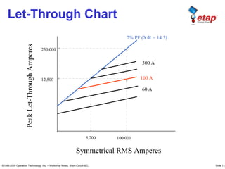
  • 112. ©1996-2009 Operation Technology, Inc. – Workshop Notes: Short-Circuit IEC Slide 112 Symmetrical RMS Amperes Peak Let-Through Amperes 100 A 60 A 7% PF (X/R = 14.3) 12,500 5,200 230,000 300 A 100,000 Let-Through Chart
  • 113. ©1996-2009 Operation Technology, Inc. – Workshop Notes: Short-Circuit IEC Slide 113 Fuse Generally: • CLF is a better short-circuit protection • Non-CLF (expulsion fuse) is a better Overload protection • Electronic fuses are typically easier to coordinate due to the electronic control adjustments
  • 114. ©1996-2009 Operation Technology, Inc. – Workshop Notes: Short-Circuit IEC Slide 114 Selectivity Criteria Typically: • Non-CLF: 140% of full load • CLF: 150% of full load • Safety Margin: 10% applied to Min Melting (consult the fuse manufacturer)
  • 115. ©1996-2009 Operation Technology, Inc. – Workshop Notes: Short-Circuit IEC Slide 115 Molded Case CB • Thermal-Magnetic • Magnetic Only • Motor Circuit Protector (MCP) • Integrally Fused (Limiters) • Current Limiting • High Interrupting Capacity • Non-Interchangeable Parts • Insulated Case (Interchange Parts) Types • Frame Size • Poles • Trip Rating • Interrupting Capability • Voltage
  • 116. ©1996-2009 Operation Technology, Inc. – Workshop Notes: Short-Circuit IEC Slide 116 MCCB
  • 117. ©1996-2009 Operation Technology, Inc. – Workshop Notes: Short-Circuit IEC Slide 117 MCCB with SST Device
  • 118. ©1996-2009 Operation Technology, Inc. – Workshop Notes: Short-Circuit IEC Slide 118 Thermal Minimum Thermal Maximum Magnetic (instantaneous)
  • 119. ©1996-2009 Operation Technology, Inc. – Workshop Notes: Short-Circuit IEC Slide 119 LVPCB • Voltage and Frequency Ratings • Continuous Current / Frame Size / Sensor • Interrupting Rating • Short-Time Rating (30 cycle) • Fairly Simple to Coordinate • Phase / Ground Settings • Inst. Override
  • 120. ©1996-2009 Operation Technology, Inc. – Workshop Notes: Short-Circuit IEC Slide 120 CB 2 CB 1 IT ST PU ST Band LT PU LT Band 480 kV CB 2 CB 1 If =30 kA
  • 121. ©1996-2009 Operation Technology, Inc. – Workshop Notes: Short-Circuit IEC Slide 121 Inst. Override
  • 122. ©1996-2009 Operation Technology, Inc. – Workshop Notes: Short-Circuit IEC Slide 122 Overload Relay / Heater • Motor overload protection is provided by a device that models the temperature rise of the winding • When the temperature rise reaches a point that will damage the motor, the motor is de- energized • Overload relays are either bimetallic, melting alloy or electronic
  • 123. ©1996-2009 Operation Technology, Inc. – Workshop Notes: Short-Circuit IEC Slide 123 Overload Heater (Mfr. Data)
  • 124. ©1996-2009 Operation Technology, Inc. – Workshop Notes: Short-Circuit IEC Slide 124 Question What is Class 10 and Class 20 Thermal OLR curves?
  • 125. ©1996-2009 Operation Technology, Inc. – Workshop Notes: Short-Circuit IEC Slide 125 Answer • At 600% Current Rating: – Class 10 for fast trip, 10 seconds or less – Class 20 for, 20 seconds or less (commonly used) – There is also Class 15, 30 for long trip time (typically provided with electronic overload relays) 6 20
  • 126. ©1996-2009 Operation Technology, Inc. – Workshop Notes: Short-Circuit IEC Slide 126 Answer
  • 127. ©1996-2009 Operation Technology, Inc. – Workshop Notes: Short-Circuit IEC Slide 127 Overload Relay / Heater • When the temperature at the combination motor starter is more than ±10 °C (±18 °F) different than the temperature at the motor, ambient temperature correction of the motor current is required. • An adjustment is required because the output that a motor can safely deliver varies with temperature. • The motor can deliver its full rated horsepower at an ambient temperature specified by the motor manufacturers, normally + 40 °C. At high temperatures (higher than + 40 °C) less than 100% of the normal rated current can be drawn from the motor without shortening the insulation life. • At lower temperatures (less than + 40 °C) more than 100% of the normal rated current could be drawn from the motor without shortening the insulation life.
  • 128. ©1996-2009 Operation Technology, Inc. – Workshop Notes: Short-Circuit IEC Slide 128 Overcurrent Relay • Time-Delay (51 – I>) • Short-Time Instantaneous ( I>>) • Instantaneous (50 – I>>>) • Electromagnetic (induction Disc) • Solid State (Multi Function / Multi Level) • Application
  • 129. ©1996-2009 Operation Technology, Inc. – Workshop Notes: Short-Circuit IEC Slide 129 © 1996-2009 Operation Technology, Inc. – Workshop Notes: Protective Device Coordination
  • 130. ©1996-2009 Operation Technology, Inc. – Workshop Notes: Short-Circuit IEC Slide 130 Time-Overcurrent Unit • Ampere Tap Calculation – Ampere Pickup (P.U.) = CT Ratio x A.T. Setting – Relay Current (IR) = Actual Line Current (IL) / CT Ratio – Multiples of A.T. = IR/A.T. Setting = IL/(CT Ratio x A.T. Setting) IL IR CT 51
  • 131. ©1996-2009 Operation Technology, Inc. – Workshop Notes: Short-Circuit IEC Slide 131 Instantaneous Unit • Instantaneous Calculation – Ampere Pickup (P.U.) = CT Ratio x IT Setting – Relay Current (IR) = Actual Line Current (IL) / CT Ratio – Multiples of IT = IR/IT Setting = IL/(CT Ratio x IT Setting) IL IR CT 50
  • 132. ©1996-2009 Operation Technology, Inc. – Workshop Notes: Short-Circuit IEC Slide 132 Relay Coordination • Time margins should be maintained between T/C curves • Adjustment should be made for CB opening time • Shorter time intervals may be used for solid state relays • Upstream relay should have the same inverse T/C characteristic as the downstream relay (CO-8 to CO-8) or be less inverse (CO-8 upstream to CO-6 downstream) • Extremely inverse relays coordinates very well with CLFs
  • 133. ©1996-2009 Operation Technology, Inc. – Workshop Notes: Short-Circuit IEC Slide 133 Situation Calculate Relay Setting (Tap, Inst. Tap & Time Dial) For This System 4.16 kV DS 5 MVA Cable 1-3/C 500 kcmil CU - EPR CB Isc = 30,000 A 6 % 50/51 Relay: IFC 53 CT 800:5
  • 134. ©1996-2009 Operation Technology, Inc. – Workshop Notes: Short-Circuit IEC Slide 134 Solution A Inrsuh 328 , 8 694 12 I = × = A 338 . 4 800 5 I I L R = × = Transformer: A kV kVA L 694 16 . 4 3 000 , 5 I = × = IL CT R IR Set Relay: A 55 1 . 52 800 5 328 , 8 ) 50 ( 1 ) 38 . 1 (6/4.338 0 . 6 4 . 5 338 . 4 % 125 = > = × = = = = × = A Inst TD A TAP A
  • 135. ©1996-2009 Operation Technology, Inc. – Workshop Notes: Short-Circuit IEC Slide 135 Question What T/C Coordination interval should be maintained between relays?
  • 136. ©1996-2009 Operation Technology, Inc. – Workshop Notes: Short-Circuit IEC Slide 136 Answer A t I B CB Opening Time + Induction Disc Overtravel (0.1 sec) + Safety margin (0.2 sec w/o Inst. & 0.1 sec w/ Inst.)
  • 137. ©1996-2009 Operation Technology, Inc. – Workshop Notes: Short-Circuit IEC Slide 137 Recloser • Recloser protects electrical transmission systems from temporary voltage surges and other unfavorable conditions. • Reclosers can automatically "reclose" the circuit and restore normal power transmission once the problem is cleared. • Reclosers are usually designed with failsafe mechanisms that prevent them from reclosing if the same fault occurs several times in succession over a short period. This insures that repetitive line faults don't cause power to switch on and off repeatedly, since this could cause damage or accelerated wear to electrical equipment. • It also insures that temporary faults such as lightning strikes or transmission switching don't cause lengthy interruptions in service.
  • 138. ©1996-2009 Operation Technology, Inc. – Workshop Notes: Short-Circuit IEC Slide 138 Recloser Types • Hydraulic • Electronic – Static Controller – Microprocessor Controller
  • 139. ©1996-2009 Operation Technology, Inc. – Workshop Notes: Short-Circuit IEC Slide 139 Recloser Curves
  • 140. ©1996-2009 Operation Technology, Inc. – Workshop Notes: Short-Circuit IEC Slide 140 TEMA 3
  • 141. ©1996-2009 Operation Technology, Inc. – Workshop Notes: Short-Circuit IEC Transient Stability
  • 142. ©1996-2009 Operation Technology, Inc. – Workshop Notes: Short-Circuit IEC Slide 142 Topics • What is Transient Stability (TS) • What Causes System Unstable • Effects When System Is Instable • Transient Stability Definition • Modeling and Data Preparation • ETAP TS Study Outputs • Power System TS Studies • Solutions to Stability Problems
  • 143. ©1996-2009 Operation Technology, Inc. – Workshop Notes: Short-Circuit IEC Slide 143 What is Transient Stability • TS is also called Rotor Angle Stability Something between mechanical system and electrical system – energy conversion • It is a Electromechanical Phenomenon Time frame in milliseconds • All Synchronous Machines Must Remain in Synchronism with One Another Synchronous generators and motors This is what system stable or unstable means
  • 144. ©1996-2009 Operation Technology, Inc. – Workshop Notes: Short-Circuit IEC Slide 144 What is Transient Stability • Torque Equation (generator case) T = mechanical torque P = number of poles φ a ir = air-gap flux Fr = rotor field MMF δ = rotor angle
  • 145. ©1996-2009 Operation Technology, Inc. – Workshop Notes: Short-Circuit IEC Slide 145 What is Transient Stability • Swing Equation M = inertia constant D = damping constant Pm e c h = input mechanical power Pe le c = output electrical power
  • 146. ©1996-2009 Operation Technology, Inc. – Workshop Notes: Short-Circuit IEC Slide 146 What Causes System Unstable • From Torque Equation T (prime mover) Rotor MMF (field winding) Air-Gap Flux (electrical system) • From Swing Equation Pmech Pelec Different time constants in mechanical and electrical systems
  • 147. ©1996-2009 Operation Technology, Inc. – Workshop Notes: Short-Circuit IEC Slide 147 What Causes System Unstable • In real operation Short-circuit Loss of excitation Prime mover failure Loss of utility connections Loss of a portion of in-plant generation Starting of a large motor Switching operations Impact loading on motors Sudden large change in load and generation
  • 148. ©1996-2009 Operation Technology, Inc. – Workshop Notes: Short-Circuit IEC Slide 148 Effects When System Is Instable Case 1: Steady-state stable Case 2: Transient stable Case 3: Small-signal unstable Case 4: First swing unstable • Swing in Rotor Angle (as well as in V, I, P, Q and f)
  • 149. ©1996-2009 Operation Technology, Inc. – Workshop Notes: Short-Circuit IEC Slide 149 Effects When System Is Instable • A 2-Machine Example • At δ = -180º (Out-of-Step, Slip the Pole)
  • 150. ©1996-2009 Operation Technology, Inc. – Workshop Notes: Short-Circuit IEC Slide 150 Effects When System Is Instable • Synchronous machine slip poles – generator tripping • Power swing • Misoperation of protective devices • Interruption of critical loads • Low-voltage conditions – motor drop-offs • Damage to equipment • Area wide blackout • …
  • 151. ©1996-2009 Operation Technology, Inc. – Workshop Notes: Short-Circuit IEC Slide 151 • Examine One Generator • Power Output Capability Curve ∀ δ is limited to 180º Transient Stability Definition
  • 152. ©1996-2009 Operation Technology, Inc. – Workshop Notes: Short-Circuit IEC Slide 152 Transient Stability Definition • Transient and Dynamic Stability Limit  After a severe disturbance, the synchronous generator reaches a steady-state operating condition without a prolonged loss of synchronism  Limit: δ < 180°during swing
  • 153. ©1996-2009 Operation Technology, Inc. – Workshop Notes: Short-Circuit IEC Slide 153 • Synchronous Machine  Machine  Exciter and AVR  Prime Mover and Governor / Load Torque  Power System Stabilizer (PSS) (Generator) Modeling and Data Preparation
  • 154. ©1996-2009 Operation Technology, Inc. – Workshop Notes: Short-Circuit IEC Slide 154 Modeling and Data Preparation
  • 155. ©1996-2009 Operation Technology, Inc. – Workshop Notes: Short-Circuit IEC Slide 155 Modeling and Data Preparation • Typical synchronous machine data
  • 156. ©1996-2009 Operation Technology, Inc. – Workshop Notes: Short-Circuit IEC Slide 156 Modeling and Data Preparation • Induction Machine  Machine  Load Torque
  • 157. ©1996-2009 Operation Technology, Inc. – Workshop Notes: Short-Circuit IEC Slide 157 Modeling and Data Preparation • Power Grid  Short-Circuit Capability  Fixed internal voltage and infinite inertia
  • 158. ©1996-2009 Operation Technology, Inc. – Workshop Notes: Short-Circuit IEC Slide 158 Modeling and Data Preparation • Load  Voltage dependency  Frequency dependency
  • 159. ©1996-2009 Operation Technology, Inc. – Workshop Notes: Short-Circuit IEC Slide 159 Modeling and Data Preparation • Load
  • 160. ©1996-2009 Operation Technology, Inc. – Workshop Notes: Short-Circuit IEC Slide 160 Modeling and Data Preparation • Events and Actions
  • 161. ©1996-2009 Operation Technology, Inc. – Workshop Notes: Short-Circuit IEC Slide 161 Modeling and Data Preparation Device Type Action Bus 3-P Fault L-G Fault Clear Fault Branch Fraction Fault Clear Fault PD Trip Close Generator Droop / Isoch Start Loss Exc. P Change V Change Delete Grid P Change V Change Delete Motor Accelerate Load Change Delete Lumped Load Load Change Delete MOV Start Wind Turbine Disturbance Gust Ramp MG Set Emergency Main
  • 162. ©1996-2009 Operation Technology, Inc. – Workshop Notes: Short-Circuit IEC Slide 162 Power System TS Studies • Fault 3-phase and single phase fault Clear fault Critical Fault Clearing Time (CFCT) Critical System Separation Time (CSST) • Bus Transfer Fast load transferring • Load Shedding Under-frequency Under-voltage • Motor Dynamic Acceleration Induction motor Synchronous motor
  • 163. ©1996-2009 Operation Technology, Inc. – Workshop Notes: Short-Circuit IEC Slide 163 Power System TS Studies • Critical Fault Clearing Time (CFCT) • Critical Separation Time (CSST) unstable unstable Cycle Clear fault Clear fault 1 cycle unstable stable 1 cycle Clear fault Clear fault CFCT Fault unstable unstable Cycle 1 cycle unstable stable 1 cycle CSST Separation Separation Separation Separation Fault
  • 164. ©1996-2009 Operation Technology, Inc. – Workshop Notes: Short-Circuit IEC Slide 164 Power System TS Studies -1 -0.8 -0.6 -0.4 -0.2 0 0.2 0.4 0.6 0.8 1 -1 -0.8 -0.6 -0.4 -0.2 0 0.2 0.4 0.6 0.8 1 Vmotor s • Fast Bus Transfer Motor residual voltage
  • 165. ©1996-2009 Operation Technology, Inc. – Workshop Notes: Short-Circuit IEC Slide 165 • Fast Bus Transfer Ttra n s fe r ≤ 10 cycles δ ≤ 90 degrees ER ≤ 1.33 per unit (133%) Power System TS Studies ES = System equivalent per unit volts per hertz EM = Motor residual per unit per hertz ER = Resultant vectorial voltage in per unit volts per hertz δ
  • 166. ©1996-2009 Operation Technology, Inc. – Workshop Notes: Short-Circuit IEC Slide 166 Power System TS Studies • Load Shedding
  • 167. ©1996-2009 Operation Technology, Inc. – Workshop Notes: Short-Circuit IEC Slide 167 Power System TS Studies • Motor Dynamic Acceleration Important for islanded system operation Motor starting impact Generator AVR action Reacceleration
  • 168. ©1996-2009 Operation Technology, Inc. – Workshop Notes: Short-Circuit IEC Slide 168 • Improve System Design  Increase synchronizing power • Design and Selection of Rotating Equipment  Use of induction machines  Increase moment of inertia  Reduce transient reactance  Improve voltage regulator and exciter characteristics Solution to Stability Problems
  • 169. ©1996-2009 Operation Technology, Inc. – Workshop Notes: Short-Circuit IEC Slide 169 • Application of Power System Stabilizer (PSS) • Add System Protections  Fast fault clearance  Load shedding  System separation Out-Of-Step relay … Solution to Stability Problems
  • 170. ©1996-2009 Operation Technology, Inc. – Workshop Notes: Short-Circuit IEC
  • 171. ©1996-2009 Operation Technology, Inc. – Workshop Notes: Short-Circuit IEC Slide 171 TEMA 4
  • 172. ©1996-2009 Operation Technology, Inc. – Workshop Notes: Short-Circuit IEC Harmonic Analysis
  • 173. ©1996-2009 Operation Technology, Inc. – Workshop Notes: Short-Circuit IEC Slide 173 ARMONICAS  Exploración de frecuencia.  Flujo Armónico de Carga.  Dimensionamiento y Diseño de Filtros.  Evaluación Automática del límite de distorsión.  Factores de la influencia del teléfono (TIF & I*T) Características principales:
  • 174. ©1996-2009 Operation Technology, Inc. – Workshop Notes: Short-Circuit IEC Slide 174
  • 175. ©1996-2009 Operation Technology, Inc. – Workshop Notes: Short-Circuit IEC Slide 175 Types of Power Quality Problems
  • 176. ©1996-2009 Operation Technology, Inc. – Workshop Notes: Short-Circuit IEC Slide 176 Waveform Distortion • Primary Types of Waveform Distortion – DC Offset – Harmonics – Interharmonics – Notching – Noise
  • 177. ©1996-2009 Operation Technology, Inc. – Workshop Notes: Short-Circuit IEC Slide 177 Harmonics • One special category of power quality problems • “Harmonics are voltages and/or currents present in an electrical system at some multiple of the fundamental frequency.” (IEEE Std 399, Brown Book)
  • 178. ©1996-2009 Operation Technology, Inc. – Workshop Notes: Short-Circuit IEC Slide 178 Nonlinear Loads • Sinusoidal voltage applied to a simple nonlinear resistor • Increasing the voltage by a few percent may cause current to double
  • 179. ©1996-2009 Operation Technology, Inc. – Workshop Notes: Short-Circuit IEC Slide 179 Fourier Representation • Any periodic waveform can be expressed as a sum of sinusoids • The sum of the sinusoids is referred to as Fourier Series (6-pulse) ) cos( 13 cos 13 1 11 cos 11 1 7 cos 7 1 3 cos 5 1 (cos 3 2 1 h h h d ac t h I t t t t t I I Φ + ⇒ + − + − = ∑ ∞ = ω ω ω ω ω ω π
  • 180. ©1996-2009 Operation Technology, Inc. – Workshop Notes: Short-Circuit IEC Slide 180 Harmonic Sources • Utilities (Power Grid) – Known as “Background Harmonic” – Pollution from other irresponsible customers – SVC, HVDC, FACTS, … – Usually a voltage source • Synchronous Generators – Due to Pitch (can be eliminated by fractional- pitch winding) and Saturation – Usually a voltage source
  • 181. ©1996-2009 Operation Technology, Inc. – Workshop Notes: Short-Circuit IEC Slide 181 Harmonic Sources (cont’d) • Transformers – Due to magnetizing branch saturation – Only at lightly loaded condition – Usually a current source • Power Electronic Devices – Charger, Converter, Inverter, UPS, VFD, SVC, HVDC, FACTS (Flexible alternating current transmission systems) … – Due to switching actions – Either a voltage source or a current source
  • 182. ©1996-2009 Operation Technology, Inc. – Workshop Notes: Short-Circuit IEC Slide 182 Harmonic Sources (cont’d) • Other Non-Linear Loads – Arc furnaces, discharge lighting, … – Due to unstable and non-linear process – Either a voltage source or a current source • In general, any load that is applied to a power system that requires other than a sinusoidal current
  • 183. ©1996-2009 Operation Technology, Inc. – Workshop Notes: Short-Circuit IEC Slide 183 Harmonic I and V
  • 184. ©1996-2009 Operation Technology, Inc. – Workshop Notes: Short-Circuit IEC Slide 184 Classification of Harmonics • Harmonics may be classified as: – Characteristic Harmonics  Generally produced by power converters – Non-Characteristic Harmonics  Typically produced by arc furnaces and discharge lighting (from non-periodical waveforms)
  • 185. ©1996-2009 Operation Technology, Inc. – Workshop Notes: Short-Circuit IEC Slide 185 Phase Angle Relationship • Fundamental Frequency
  • 186. ©1996-2009 Operation Technology, Inc. – Workshop Notes: Short-Circuit IEC Slide 186 Phase Angle Relationship • Third Order
  • 187. ©1996-2009 Operation Technology, Inc. – Workshop Notes: Short-Circuit IEC Slide 187 Phase Angle Relationship • Fifth Order • Seventh Order
  • 188. ©1996-2009 Operation Technology, Inc. – Workshop Notes: Short-Circuit IEC Slide 188 Order vs. Sequence
  • 189. ©1996-2009 Operation Technology, Inc. – Workshop Notes: Short-Circuit IEC Slide 189 Characteristic Harmonics
  • 190. ©1996-2009 Operation Technology, Inc. – Workshop Notes: Short-Circuit IEC Slide 190 Characteristic Harmonics (cont’d)
  • 191. ©1996-2009 Operation Technology, Inc. – Workshop Notes: Short-Circuit IEC Slide 191 Harmonic Spectrum %
  • 192. ©1996-2009 Operation Technology, Inc. – Workshop Notes: Short-Circuit IEC Slide 192 Harmonic-Related Problems • Motors and Generators – Increased heating due to iron and copper losses – Reduced efficiency and torque – Higher audible noise – Cogging or crawling – Mechanical oscillations
  • 193. ©1996-2009 Operation Technology, Inc. – Workshop Notes: Short-Circuit IEC Slide 193 Harmonic-Related Problems (cont’d) • Transformers – Parasitic heating – Increased copper, stray flux and iron losses • Capacitors (var compensators) – Possibility of system resonance – Increased heating and voltage stress – Shortened capacitor life
  • 194. ©1996-2009 Operation Technology, Inc. – Workshop Notes: Short-Circuit IEC Slide 194 Harmonic-Related Problems (cont’d) • Power Cables – Involved in system resonance – Voltage stress and corona leading to dielectric failure – Heating and derating • Neutrals of four-wire systems (480/277V; 120/208V) – Overheating • Fuses – Blowing
  • 195. ©1996-2009 Operation Technology, Inc. – Workshop Notes: Short-Circuit IEC Slide 195 Harmonic-Related Problems (cont’d) • Switchgears – Increased heating and losses – Reduced steady-state current carrying capability – Shortened insulation components life • Relays – Possibility of misoperation • Metering – Affected readings
  • 196. ©1996-2009 Operation Technology, Inc. – Workshop Notes: Short-Circuit IEC Slide 196 Harmonic-Related Problems (cont’d) • Communication Systems – Interference by higher frequency electromagnetic field • Electronic Equipment (computers, PLC) – Misoperation • System – Resonance (serial and parallel) – Poor power factor
  • 197. ©1996-2009 Operation Technology, Inc. – Workshop Notes: Short-Circuit IEC Slide 197 Parallel Resonance • Total impedance at resonance frequency increases • High circulating current will flow in the capacitance-inductance loop
  • 198. ©1996-2009 Operation Technology, Inc. – Workshop Notes: Short-Circuit IEC Slide 198 Parallel Resonance
  • 199. ©1996-2009 Operation Technology, Inc. – Workshop Notes: Short-Circuit IEC Slide 199 Capacitor Banks
  • 200. ©1996-2009 Operation Technology, Inc. – Workshop Notes: Short-Circuit IEC Slide 200 Capacitor Banks
  • 201. ©1996-2009 Operation Technology, Inc. – Workshop Notes: Short-Circuit IEC Slide 201 Capacitor Banks Say, Seventh Harmonic Current = 5% of 1100A = 55 A
  • 202. ©1996-2009 Operation Technology, Inc. – Workshop Notes: Short-Circuit IEC Slide 202 Capacitor Banks Resistance = 1% including cable and transformer CAF = X/R = 7*0.0069/0.0012 =40.25 Resonant Current = 55*40.25 = 2214 A
  • 203. ©1996-2009 Operation Technology, Inc. – Workshop Notes: Short-Circuit IEC Slide 203 Parallel Resonance (cont’d) Cause: Impacts: 1. Excessive capacitor fuse operation 2. Capacitor failures 3. Incorrect relay tripping 4. Telephone interference 5. Overheating of equipment Source inductance resonates with capacitor bank at a frequency excited by the facilities harmonic sources
  • 204. ©1996-2009 Operation Technology, Inc. – Workshop Notes: Short-Circuit IEC Slide 204 Harmonic Distortion Measurements • Total Harmonic Distortion (THD) – Also known as Harmonic Distortion Factor (HDF), is the most popular index to measure the level of harmonic distortion to voltage and current – Ratio of the RMS of all harmonics to the fundamental component – For an ideal system THD = 0% – Potential heating value of the harmonics relative to the fundamental
  • 205. ©1996-2009 Operation Technology, Inc. – Workshop Notes: Short-Circuit IEC Slide 205 Harmonic Distortion Measurements (cont’d) 1 2 2 F F THD i ∑ ∞ = Where Fi is the amplitude of the ith harmonic, and F1 is that for the fundamental component. – Good indicator of additional losses due to current flowing through a conductor – Not a good indicator of voltage stress in a capacitor (related to peak value of voltage waveform, not its heating value)
  • 206. ©1996-2009 Operation Technology, Inc. – Workshop Notes: Short-Circuit IEC Slide 206 Harmonic Distortion Example Find THD for this waveform
  • 207. ©1996-2009 Operation Technology, Inc. – Workshop Notes: Short-Circuit IEC Slide 207 Harmonic Example • Find THD for this Harmonic Spectrum
  • 208. ©1996-2009 Operation Technology, Inc. – Workshop Notes: Short-Circuit IEC Slide 208 Adjustable Speed Drive – Current Distortion
  • 209. ©1996-2009 Operation Technology, Inc. – Workshop Notes: Short-Circuit IEC Slide 209 Adjustable Speed Drive – Voltage Distortion
  • 210. ©1996-2009 Operation Technology, Inc. – Workshop Notes: Short-Circuit IEC Slide 210 Harmonic Distortion Measurements (cont’d) • Individual Harmonic Distortion (IHD) - Ratio of a given harmonic to fundamental - To track magnitude of individual harmonic 1 F F IHD i = • Root Mean Square (RMS) - Total - Root Mean Square of fundamental plus all harmonics - Equal to fundamental RMS if Harmonics are zero ∑ ∞ = 1 2 i F RMS
  • 211. ©1996-2009 Operation Technology, Inc. – Workshop Notes: Short-Circuit IEC Slide 211 Harmonic Distortion Measurements (cont’d) • Arithmetic Summation (ASUM) – Arithmetic summation of magnitudes of all components (fundamental and all harmonics) – Directly adds magnitudes of all components to estimate crest value of voltage and current – Evaluation of the maximum withstanding ratings of a device ∑ ∞ = 1 i F ASUM
  • 212. ©1996-2009 Operation Technology, Inc. – Workshop Notes: Short-Circuit IEC Slide 212 Harmonic Distortion Measurements (cont’d) • Telephone Influence Factor (TIF) – Weighted THD – Weights based on interference to an audio signal in the same frequency range – Current TIF shows impact on adjacent communication systems ( ) 2 1 2 1 ∑ ∑ ∞ ∞ = i i i F F W TIF
  • 213. ©1996-2009 Operation Technology, Inc. – Workshop Notes: Short-Circuit IEC Slide 213 Harmonic Distortion Measurements (cont’d) • I*T Product (I*T) – A product current components (fundamental and harmonics) and weighting factors ∑ = ⋅ = • H h h h T I T I 1 2 ) ( where Ih = current component Th = weighting factor h = harmonic order (h=1 for fundamental) H = maximum harmonic order to account
  • 214. ©1996-2009 Operation Technology, Inc. – Workshop Notes: Short-Circuit IEC Slide 214 Triplen Harmonics • Odd multiples of the third harmonic (h = 3, 9, 15, 21, …) • Important issue for grounded-wye systems with neutral current • Overloading and TIF problems • Misoperation of devices due to presence of harmonics on the neutral
  • 215. ©1996-2009 Operation Technology, Inc. – Workshop Notes: Short-Circuit IEC Slide 215 Triplen Harmonics
  • 216. ©1996-2009 Operation Technology, Inc. – Workshop Notes: Short-Circuit IEC Slide 216 Winding Connections • Delta winding provides ampere turn balance • Triplen Harmonics cannot flow • When currents are balanced Triplens behave as Zero Sequence currents • Used in Utility Distribution Substations • Delta winding connected to Transmission • Balanced Triplens can flow • Present in equal proportions on both sides • Many loads are served in this fashion
  • 217. ©1996-2009 Operation Technology, Inc. – Workshop Notes: Short-Circuit IEC Slide 217 Implications • Neutral connections are susceptible to overheating when serving single-phase loads on the Y side that have high 3rd Harmonic • Measuring current on delta side will not show the triplens and therefore do not give a true idea of the heating the transformer is subjected to • The flow of triplens can be interrupted by appropriate isolation transformer connection • Removing the neutral connection in one or both Y windings blocks the flow of Triplen harmonic current • Three legged core transformers behave as if they have a “phantom” delta tertiary winding
  • 218. ©1996-2009 Operation Technology, Inc. – Workshop Notes: Short-Circuit IEC Slide 218 Modeling in Harmonic Analysis • Motors and Machines – Represented by their equivalent negative sequence reactance • Lines and Cables – Series impedance for low frequencies – Long line correction including transposition and distributed capacitance
  • 219. ©1996-2009 Operation Technology, Inc. – Workshop Notes: Short-Circuit IEC Slide 219 Modeling in Harmonic Analysis (cont’d) • Transformers – Leakage impedance – Magnetizing impedance • Loads – Static loads reduce peak resonant impedance – Motor loads shift resonant frequency due to motor inductance
  • 220. ©1996-2009 Operation Technology, Inc. – Workshop Notes: Short-Circuit IEC Slide 220 Reducing System Harmonics • Add Passive Filters – Shunt or Single Tuned Filters – Broadband Filters or Band Pass Filters – Provide low impedance path for harmonic current – Least expensive
  • 221. ©1996-2009 Operation Technology, Inc. – Workshop Notes: Short-Circuit IEC Slide 221 Reducing System Harmonics (cont’d) • Increase Pulse Numbers – Increasing pulse number of convert circuits – Limited by practical control problems
  • 222. ©1996-2009 Operation Technology, Inc. – Workshop Notes: Short-Circuit IEC Slide 222 Reducing System Harmonics (cont’d) • Apply Transformer Phase Shifting – Using Phase Shifting Transformers – Achieve higher pulse operation of the total converter installation • In ETAP – Phase shift is specified in the tab page of the transformer editor
  • 223. ©1996-2009 Operation Technology, Inc. – Workshop Notes: Short-Circuit IEC Slide 223 Reducing System Harmonics (cont’d) • Either standard phase shift or special phase shift can be used
  • 224. ©1996-2009 Operation Technology, Inc. – Workshop Notes: Short-Circuit IEC Slide 224 Reducing System Harmonics (cont’d) • Add Active Filters – Instantly adapts to changing source and load conditions – Costly – MVA Limitation
  • 225. ©1996-2009 Operation Technology, Inc. – Workshop Notes: Short-Circuit IEC Slide 225 Voltage Distortion Limits Recommended Practices for Utilities (IEEE 519): Bus Voltage At PCC Individual Distortion (%) Total Voltage Distortion THD (%) 69 kV and below 3.0 5.0 69.001 kV through 161kV 1.5 2.5 161.001 and above 1.0 1.5 In ETAP: Specify Harmonic Distortion Limits in Harmonic Page of Bus Editor:
  • 226. ©1996-2009 Operation Technology, Inc. – Workshop Notes: Short-Circuit IEC Slide 226 Current Distortion Limits Recommended Practices for General Distribution Systems (IEEE 519):
  • 227. ©1996-2009 Operation Technology, Inc. – Workshop Notes: Short-Circuit IEC Slide 227 TEMA 5
  • 228. ©1996-2009 Operation Technology, Inc. – Workshop Notes: Short-Circuit IEC Motor Starting Dynamic Acceleration
  • 229. ©1996-2009 Operation Technology, Inc. – Workshop Notes: Short-Circuit IEC Slide 229 ARRANQUE DE MOTORES  Aceleración dinámica de motores.  Parpadeo (Flicker) de tensión.  Modelos dinámicos de motores.  Arranque estático de motores.  Varios dispositivos de arranque.  Transición de carga. Características principales:
  • 230. ©1996-2009 Operation Technology, Inc. – Workshop Notes: Short-Circuit IEC Slide 230
  • 231. ©1996-2009 Operation Technology, Inc. – Workshop Notes: Short-Circuit IEC Slide 231 Why to Do MS Studies? • Ensure that motor will start with voltage drop • If Ts t <Tlo a d at s=1, then motor will not start • If Tm=Tlo a d at s<sr, motor can not reach rated speed • Torque varies as (voltage)^2 • Ensure that voltage drop will not disrupt other loads • Utility bus voltage >95% • 3% Sag represents a point when light flicker becomes visible • 5% Sag represents a point when light flicker becomes irritating • MCC bus voltage >80% • Generation bus voltage > 93%
  • 232. ©1996-2009 Operation Technology, Inc. – Workshop Notes: Short-Circuit IEC Slide 232 Why to Do MS Studies? • Ensure motor feeders sized adequately (Assuming 100% voltage at Switchboard or MCC) • LV cable voltage drop at starting < 20% • LV cable voltage drop when running at full-load < 5% • HV cable voltage drop at starting < 15% • HV cable voltage drop when running at full-load < 3% • Maximum motor size that can be started across the line • Motor kW < 1/6 kW rating of generator (islanded) • For 6 MW of islanded generation, largest motor size < 1 MW
  • 233. ©1996-2009 Operation Technology, Inc. – Workshop Notes: Short-Circuit IEC Slide 233 Motor Sizing • Positive Displacement Pumps / Rotary Pumps • p = Pressure in psi • Q = fluid flow in gpm • n = efficiency • Centrifugal Pumps • H = fluid head in feet
  • 234. ©1996-2009 Operation Technology, Inc. – Workshop Notes: Short-Circuit IEC Slide 234 Motor Types • Synchronous • Salient Pole • Round Rotor • Induction • Wound Rotor (slip-ring) • Single Cage CKT Model • Squirrel Cage (brushless) • Double Cage CKT Model
  • 235. ©1996-2009 Operation Technology, Inc. – Workshop Notes: Short-Circuit IEC Slide 235 Induction Motor Advantages • Squirrel Cage • Slightly higher efficiency and power factor • Explosive proof • Wound Rotor • Higher starting torque • Lower starting current • Speed varied by using external resistances
  • 236. ©1996-2009 Operation Technology, Inc. – Workshop Notes: Short-Circuit IEC Slide 236 Typical Rotor Construction • Rotor slots are not parallel to the shaft but skewed
  • 237. ©1996-2009 Operation Technology, Inc. – Workshop Notes: Short-Circuit IEC Slide 237 Wound Rotor
  • 238. ©1996-2009 Operation Technology, Inc. – Workshop Notes: Short-Circuit IEC Slide 238 Operation of Induction Motor • AC applied to stator winding • Creates a rotating stator magnetic field in air gap • Field induces currents (voltages) in rotor • Rotor currents create rotor magnetic field in air gap • Torque is produced by interaction of air gap fields
  • 239. ©1996-2009 Operation Technology, Inc. – Workshop Notes: Short-Circuit IEC Slide 239 Slip Frequency • Slip represents the inability of the rotor to keep up with the stator magnetic field • Slip frequency S = (ωs-ωn)/ωs where ωs = 120f/P ωn = mech speed
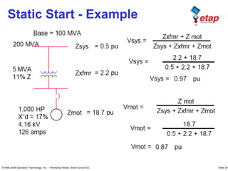
  • 240. ©1996-2009 Operation Technology, Inc. – Workshop Notes: Short-Circuit IEC Slide 240 Static Start - Example
  • 241. ©1996-2009 Operation Technology, Inc. – Workshop Notes: Short-Circuit IEC Slide 241 Static Start - Example
  • 242. ©1996-2009 Operation Technology, Inc. – Workshop Notes: Short-Circuit IEC Slide 242 Service Factor
  • 243. ©1996-2009 Operation Technology, Inc. – Workshop Notes: Short-Circuit IEC Slide 243 Inrush Current
  • 244. ©1996-2009 Operation Technology, Inc. – Workshop Notes: Short-Circuit IEC Slide 244 Resistance / Reactance • Torque Slip Curve is changed by altering resistance / reactance of rotor bars. • Resistance ↑ by ↓cross sectional area or using higher resistivity material like brass. • Reactance ↑ by placing conductor deeper in the rotor cylinder or by closing the slot at the air gap.
  • 245. ©1996-2009 Operation Technology, Inc. – Workshop Notes: Short-Circuit IEC Slide 245 Rotor Bar Resistance ↑ • Increase Starting Torque • Lower Starting Current • Lower Full Load Speed • Lower Efficiency • No Effect on Breakdown Torque
  • 246. ©1996-2009 Operation Technology, Inc. – Workshop Notes: Short-Circuit IEC Slide 246 Rotor Bar Reactance ↑ • Lower Starting Torque • Lower Starting Current • Lower Breakdown Torque • No effect on Full Load Conditions
  • 247. ©1996-2009 Operation Technology, Inc. – Workshop Notes: Short-Circuit IEC Slide 247 Motor Torque Curves
  • 248. ©1996-2009 Operation Technology, Inc. – Workshop Notes: Short-Circuit IEC Slide 248 Rotor Bar Design • Cross section Large (low resistance) and positioned deep in the rotor (high reactance). (Starting Torque is normal and starting current is low). • Double Deck with small conductor of high resistance. During starting, most current flows through the upper deck due to high reactance of lower deck. (Starting Torque is high and starting current is low).
  • 249. ©1996-2009 Operation Technology, Inc. – Workshop Notes: Short-Circuit IEC Slide 249 Rotor Bar Design • Bars are made of Brass or similar high resistance material. Bars are close to surface to reduce leakage reactance. (Starting torque is high and starting current is low).
  • 250. ©1996-2009 Operation Technology, Inc. – Workshop Notes: Short-Circuit IEC Slide 250 Load Torque – ID Fan
  • 251. ©1996-2009 Operation Technology, Inc. – Workshop Notes: Short-Circuit IEC Slide 251 Load Torque – FD Fan
  • 252. ©1996-2009 Operation Technology, Inc. – Workshop Notes: Short-Circuit IEC Slide 252 Load Torque – C. Pump
  • 253. ©1996-2009 Operation Technology, Inc. – Workshop Notes: Short-Circuit IEC Slide 253 Motor Torque – Speed Curve
  • 254. ©1996-2009 Operation Technology, Inc. – Workshop Notes: Short-Circuit IEC Slide 254 Double Cage Motor
  • 255. ©1996-2009 Operation Technology, Inc. – Workshop Notes: Short-Circuit IEC Slide 255 Motor Full Load Torque • For example, 30 HP 1765 RPM Motor
  • 256. ©1996-2009 Operation Technology, Inc. – Workshop Notes: Short-Circuit IEC Slide 256 Motor Efficiency • kW Saved = HP * 0.746 (1/Old – 1/New) • $ Savings = kW Saved * Hrs /Year * $/kWh
  • 257. ©1996-2009 Operation Technology, Inc. – Workshop Notes: Short-Circuit IEC Slide 257 Acceleration Torque • Greater Acceleration Torque means higher inertia that can be handled by the motor without approaching thermal limits
  • 258. ©1996-2009 Operation Technology, Inc. – Workshop Notes: Short-Circuit IEC Slide 258 Acceleration Torque P
  • 259. ©1996-2009 Operation Technology, Inc. – Workshop Notes: Short-Circuit IEC Slide 259 Operating Range • Motor, Generator, or Brake
  • 260. ©1996-2009 Operation Technology, Inc. – Workshop Notes: Short-Circuit IEC Slide 260 0.8 1.0 kvar Load(kva) Terminal Voltage Terminal Current Terminal Voltage 0.8 1.0 P = Tm Wm , As Vt ( terminal voltage ) changes from 0.8 to 1.1 pu, Wm changes by a very small amount. There fore, P is approx constant since Tm (α w²m) is approx. constant L1 Ir Rated Conditions • Constant Power
  • 261. ©1996-2009 Operation Technology, Inc. – Workshop Notes: Short-Circuit IEC Slide 261 0.9 1.0 Kva LR Terminal Voltage Terminal Voltage 0.9 1.0 .8 kva LR Vt (pu) Vt (pu) .9 I LR I LR P It KVA LR = Loched - rotor KVA at rated voltage = 2HP 2 ≡ Code letter factor ≡ Locked – rotor KVA ∕ HP Z st = KVA B KVR ² KVA LR KVB Pu, Rst = Zst cos θ st , Xst= Zst sin θ st ______ ____ KVR = rated voltage KVB = Base voltage KVAB = Base power Starting Conditions • Constant Impedance Starting Conditions Constant Impedance
  • 262. ©1996-2009 Operation Technology, Inc. – Workshop Notes: Short-Circuit IEC Slide 262 ws wm v1 p R Load Voltage Variation 0 I 80% voltage 100% voltage ws wm 0 T T st T’ st Tst α ( operating voltage) ² Rated voltage _____________ Rated voltage _____________ Ist α ( operating voltage) • Torque is proportional to V^2 • Current is proportional to V I 80% V 100% V
  • 263. ©1996-2009 Operation Technology, Inc. – Workshop Notes: Short-Circuit IEC Slide 263 Frequency Variation • As frequency decreases, peak torque shifts toward lower speed as synchronous speed decreases. • As frequency decrease, current increases due reduced impedance. T em WS1 WS2 Wm F1 F2 › F1 0 I WS1 WS2 Wm F1 F2 › F1 0 W3 = 120f P ___ RPM Adjustable speed drive : Typical speed range for variable torque loads such as pumps and fans is 3/1,maximun is 8/1 ( 1.5 to 60 Hz)
  • 264. ©1996-2009 Operation Technology, Inc. – Workshop Notes: Short-Circuit IEC Slide 264 Number of Poles Variation • As Pole number increases, peak torque shifts toward lower speed as synchronous speed decreases. T em W′S WS Wm 0 2 P - poles P - poles P R Load Nro. of poles variation W′S = WS ___ 2
  • 265. ©1996-2009 Operation Technology, Inc. – Workshop Notes: Short-Circuit IEC Slide 265 Rotor Z Variation • Increasing rotor Z will shift peak torque towards lower speed. S R Q P r1 r2 r3 r4 r1 › r2 › r3 › r4 Rotor – Resistance Variation
  • 266. ©1996-2009 Operation Technology, Inc. – Workshop Notes: Short-Circuit IEC Slide 266 Modeling of Elements • Switching motors – Zlr, circuit model, or characteristic model • Synch generator - constant voltage behind X’d • Utility - constant voltage behind X”d • Branches – Same as in Load Flow • Non-switching Load – Same as Load flow • All elements must be initially energized, including motors to start
  • 267. ©1996-2009 Operation Technology, Inc. – Workshop Notes: Short-Circuit IEC Slide 267 Motor Modeling 1. Operating Motor – Constant KVA Load 1. Starting Motor – During Acceleration – Constant Impedance – Locked-Rotor Impedance – Circuit Models Characteristic Curves After Acceleration – Constant KVA Load
  • 268. ©1996-2009 Operation Technology, Inc. – Workshop Notes: Short-Circuit IEC Slide 268 Locked-Rotor Impedance • ZLR = RLR +j XLR (10 – 25 %) • PFLR is much lower than operating PD. Approximate starting PF of typical squirrel cage induction motor: POWER FACTOR HORSE POWER RATING
  • 269. ©1996-2009 Operation Technology, Inc. – Workshop Notes: Short-Circuit IEC Slide 269 Circuit Model I • Single Cage Rotor – “Single1” – constant rotor resistance and reactance
  • 270. ©1996-2009 Operation Technology, Inc. – Workshop Notes: Short-Circuit IEC Slide 270 Circuit Model II • Single Cage Rotor – “Single2” - deep bar effect, rotor resistance and reactance vary with speed [Xm is removed]
  • 271. ©1996-2009 Operation Technology, Inc. – Workshop Notes: Short-Circuit IEC Slide 271 Circuit Model III • Double Cage Rotor – “DB1” – integrated rotor cages
  • 272. ©1996-2009 Operation Technology, Inc. – Workshop Notes: Short-Circuit IEC Slide 272 Circuit Model IV • Double Cage Rotor – “DB2” – independent rotor cages
  • 273. ©1996-2009 Operation Technology, Inc. – Workshop Notes: Short-Circuit IEC Slide 273 Characteristic Model • Motor Torque, I, and PF as function of Slip – Static Model
  • 274. ©1996-2009 Operation Technology, Inc. – Workshop Notes: Short-Circuit IEC Slide 274 Calculation Methods I • Static Motor Starting – Time domain using static model – Switching motors modeled as Zlr during starting and constant kVA load after starting – Run load flow when any change in system • Dynamic Motor Starting – Time domain using dynamic model and inertia model – Dynamic model used for the entire simulation – Requires motor and load dynamic (characteristic) model
  • 275. ©1996-2009 Operation Technology, Inc. – Workshop Notes: Short-Circuit IEC Slide 275 Calculation Methods II
  • 276. ©1996-2009 Operation Technology, Inc. – Workshop Notes: Short-Circuit IEC Slide 276 Static versus Dynamic • Use Static Model When – Concerned with effect of motor starting on other loads – Missing dynamic motor information • Use Dynamic Model When – Concerned with actual acceleration time – Concerned if motor will actually start
  • 277. ©1996-2009 Operation Technology, Inc. – Workshop Notes: Short-Circuit IEC Slide 277 MS Simulation Features • Start/Stop induction/synchronous motors • Switching on/off static load at specified loading category • Simulate MOV opening/closing operations • Change grid or generator operating category • Simulate transformer LTC operation • Simulate global load transition • Simulate various types of starting devices • Simulate load ramping after motor acceleration
  • 278. ©1996-2009 Operation Technology, Inc. – Workshop Notes: Short-Circuit IEC Slide 278 Automatic Alert • Starting motor terminal V • Motor acceleration failure • Motor thermal damage • Generator rating • Generator engine continuous & peak rating • Generator exciter peak rating • Bus voltage • Starting motor bus • Grid/generator bus • HV, MV, and LV bus • User definable minimum time span
  • 279. ©1996-2009 Operation Technology, Inc. – Workshop Notes: Short-Circuit IEC Slide 279 Starting Devices Types • Auto-Transformer • Stator Resistor • Stator Reactor • Capacitor at Bus • Capacitor at Motor Terminal • Rotor External Resistor • Rotor External Reactor • Y/D Winding • Partial Wing • Soft Starter • Stator Current Limit – Stator Current Control – Voltage Control – Torque Control
  • 280. ©1996-2009 Operation Technology, Inc. – Workshop Notes: Short-Circuit IEC Slide 280 Starting Device • Comparison of starting conditions
  • 281. ©1996-2009 Operation Technology, Inc. – Workshop Notes: Short-Circuit IEC Slide 281 Starting Device – AutoXFMR • C4 and C3 closed initially • C4 opened, C2 is closed with C3 still closed. Finally C3 is open
  • 282. ©1996-2009 Operation Technology, Inc. – Workshop Notes: Short-Circuit IEC Slide 282 Starting Device – AutoXFMR • Autotransformer starting MCC M Autotransformer starter line Vmcc EX. 50% Tap VMCC 50% tap 5VMCC IST 3IST VM PFST ( with autotransformer) = PFST ( without autotransformer)
  • 283. ©1996-2009 Operation Technology, Inc. – Workshop Notes: Short-Circuit IEC Slide 283 Starting Device – YD Start • During Y connection Vs = VL / √3 • Phase current Iy = Id / √3 and 3 to 1 reduction in torque
  • 284. ©1996-2009 Operation Technology, Inc. – Workshop Notes: Short-Circuit IEC Slide 284 Starting Device – Rotor R
  • 285. ©1996-2009 Operation Technology, Inc. – Workshop Notes: Short-Circuit IEC Slide 285 Starting Device – Stator R • Resistor VMCC 50% tap 5VMCC VM RLR XLR RL XL PFST ( with resistor) = 1-[pu tap setting ]² * [ 1- (PFST without resistor)²] = 1- (0.5)² * [1-(PFST)²]
  • 286. ©1996-2009 Operation Technology, Inc. – Workshop Notes: Short-Circuit IEC Slide 286 VMCC 50% tap 5VMCC VM RLR XLR RL XL Starting Device Stator X • Reactor PFST ( with reactor) = [pu tap setting ] * PFST (without reactor)
  • 287. ©1996-2009 Operation Technology, Inc. – Workshop Notes: Short-Circuit IEC Slide 287 Transformer LTC Modeling • LTC operations can be simulated in motor starting studies • Use global or individual Tit and Tot V limit Tit Tot T
  • 288. ©1996-2009 Operation Technology, Inc. – Workshop Notes: Short-Circuit IEC Slide 288 MOV Modeling I • Represented as an impedance load during operation – Each stage has own impedance based on I, pf, Vr – User specifies duration and load current for each stage • Operation type depends on MOV status – Open statusclosing operation – Close statusopening operation
  • 289. ©1996-2009 Operation Technology, Inc. – Workshop Notes: Short-Circuit IEC Slide 289 MOV Modeling II • Five stages of operation Opening Closing Acceleration Acceleration No load No load Unseating Travel Travel Seating Stall Stall • Without hammer blow  Skip “No Load” period • With a micro switch  Skip “Stall” period • Operating stage time extended if Vmtr < Vlimit
  • 290. ©1996-2009 Operation Technology, Inc. – Workshop Notes: Short-Circuit IEC Slide 290 MOV Closing • With Hammer Blow- MOV Closing
  • 291. ©1996-2009 Operation Technology, Inc. – Workshop Notes: Short-Circuit IEC Slide 291 MOV Opening • With Hammer Blow- MOV Opening
  • 292. ©1996-2009 Operation Technology, Inc. – Workshop Notes: Short-Circuit IEC Slide 292 UNSETTING TRAVEL VMTR < V LIMIT STALL ACCL I MOV Voltage Limit • Effect of Voltage Limit Violation Tacc Tpos Travel Tstl
  • 293. ©1996-2009 Operation Technology, Inc. – Workshop Notes: Short-Circuit IEC Slide 293 TEMA 6
  • 294. ©1996-2009 Operation Technology, Inc. – Workshop Notes: Short-Circuit IEC Short-Circuit ANSI Standard
  • 295. ©1996-2009 Operation Technology, Inc. – Workshop Notes: Short-Circuit IEC Slide 295 CORTO CIRCUITO  Estándar de ANSI/IEEE & IEC.  Análisis de fallas transitorias (IEC 61363).  Efecto de Arco (NFPA 70E- 2000)  Integrado con coordinación de dispositivos de protección.  Evaluación automática de dispositivos. Características principales:
  • 296. ©1996-2009 Operation Technology, Inc. – Workshop Notes: Short-Circuit IEC Slide 296
  • 297. ©1996-2009 Operation Technology, Inc. – Workshop Notes: Short-Circuit IEC Slide 297 Types of SC Faults •Three-Phase Ungrounded Fault •Three-Phase Grounded Fault •Phase to Phase Ungrounded Fault •Phase to Phase Grounded Fault •Phase to Ground Fault Fault Current •IL -G can range in utility systems from a few percent to possibly 115 % ( if Xo < X1 ) of I3 -p h a s e (85% of all faults). •In industrial systems the situation IL -G > I3 -p h a s e is rare. Typically IL -G ≅ .87 * I3 -p h a s e •In an industrial system, the three-phase fault condition is frequently the only one considered, since this type of fault generally results in Maximum current. Short-Circuit Analysis
  • 298. ©1996-2009 Operation Technology, Inc. – Workshop Notes: Short-Circuit IEC Slide 298 Purpose of Short-Circuit Studies • A Short-Circuit Study can be used to determine any or all of the following: – Verify protective device close and latch capability – Verify protective device Interrupting capability – Protect equipment from large mechanical forces (maximum fault kA) – I2 t protection for equipment (thermal stress) – Selecting ratings or settings for relay coordination
  • 299. ©1996-2009 Operation Technology, Inc. – Workshop Notes: Short-Circuit IEC Slide 299 System Components Involved in SC Calculations • Power Company Supply • In-Plant Generators • Transformers (using negative tolerance) • Reactors (using negative tolerance) • Feeder Cables and Bus Duct Systems (at lower temperature limits)
  • 300. ©1996-2009 Operation Technology, Inc. – Workshop Notes: Short-Circuit IEC Slide 300 System Components Involved in SC Calculations • Overhead Lines (at lower temperature limit) • Synchronous Motors • Induction Motors • Protective Devices • Y0 from Static Load and Line Cable
  • 301. ©1996-2009 Operation Technology, Inc. – Workshop Notes: Short-Circuit IEC Slide 301 Elements That Contribute Current to a Short-Circuit • Generator • Power Grid • Synchronous Motors • Induction Machines • Lumped Loads (with some % motor load) • Inverters • I0 from Yg-Delta Connected Transformer
  • 302. ©1996-2009 Operation Technology, Inc. – Workshop Notes: Short-Circuit IEC Slide 302 Elements Do Not Contribute Current in PowerStation • Static Loads • Motor Operated Valves • All Shunt Y Connected Branches
  • 303. ©1996-2009 Operation Technology, Inc. – Workshop Notes: Short-Circuit IEC Slide 303 ) t Sin( Vm v(t) θ ω + ∗ = i(t) v(t) Short-Circuit Phenomenon
  • 304. ©1996-2009 Operation Technology, Inc. – Workshop Notes: Short-Circuit IEC Slide 304                     Offset) (DC Transient State Steady t ) - sin( Z Vm ) - t sin( Z Vm i(t) (1) ) t Sin( Vm dt di L Ri v(t) L R - e × × + + × = + × = + = φ θ φ θ ω θ ω expression following the yields 1 equation Solving i(t) v(t)
  • 305. ©1996-2009 Operation Technology, Inc. – Workshop Notes: Short-Circuit IEC Slide 305 DC Current AC Current (Symmetrical) with No AC Decay © 1996-2009 Operation Technology, Inc. – Workshop Notes: Short-Circuit ANSI Slide 305
  • 306. ©1996-2009 Operation Technology, Inc. – Workshop Notes: Short-Circuit IEC Slide 306 AC Fault Current Including the DC Offset (No AC Decay) © 1996-2009 Operation Technology, Inc. – Workshop Notes: Short-Circuit ANSI Slide 306
  • 307. ©1996-2009 Operation Technology, Inc. – Workshop Notes: Short-Circuit IEC Slide 307 Machine Reactance ( λ = L I ) AC Decay Current
  • 308. ©1996-2009 Operation Technology, Inc. – Workshop Notes: Short-Circuit IEC Slide 308 Fault Current Including AC & DC Decay
  • 309. ©1996-2009 Operation Technology, Inc. – Workshop Notes: Short-Circuit IEC Slide 309 1) The ANSI standards handle the AC Decay by varying machine impedance during a fault. 2) The ANSI standards handle the the dc offset by applying multiplying factors. The ANSI Terms for this current are: •Momentary Current •Close and Latch Current •First Cycle Asymmetrical Current ANSI ANSI Calculation Methods
  • 310. ©1996-2009 Operation Technology, Inc. – Workshop Notes: Short-Circuit IEC Slide 310 Sources •Synchronous Generators •Synchronous Motors & Condensers •Induction Machines •Electric Utility Systems (Power Grids) Models All sources are modeled by an internal voltage behind its impedance. E = Prefault Voltage R = Machine Armature Resistance X = Machine Reactance (X”d, X’d, Xd) Sources and Models of Fault Currents in ANSI Standards
  • 311. ©1996-2009 Operation Technology, Inc. – Workshop Notes: Short-Circuit IEC Slide 311 Synchronous Reactance Transient Reactance Subtransient Reactance Synchronous Generators Synchronous Generators are modeled in three stages. Synchronous Motors & Condensers Act as a generator to supply fault current. This current diminishes as the magnetic field in the machine decays. Induction Machines Treated the same as synchronous motors except they do not contribute to the fault after 2 sec. Electric Utility Systems The fault current contribution tends to remain constant.
  • 312. ©1996-2009 Operation Technology, Inc. – Workshop Notes: Short-Circuit IEC Slide 312 ½ Cycle Network This is the network used to calculate momentary short-circuit current and protective device duties at the ½ cycle after the fault. 1 ½ to 4 Cycle Network This network is used to calculate the interrupting short-circuit current and protective device duties 1.5-4 cycles after the fault. 30-Cycle Network This is the network used to calculate the steady-state short-circuit current and settings for over current relays after 30 cycles.
  • 313. ©1996-2009 Operation Technology, Inc. – Workshop Notes: Short-Circuit IEC Slide 313 ½ Cycle 1 ½ to 4 Cycle 30 Cycle Utility X”d X”d X”d Turbo Generator X”d X”d X’d Hydro-Gen with Amortisseur winding X”d X”d X’d Hydro-Gen without Amortisseur winding 0.75*X”d 0.75*X”d X’d Condenser X”d X”d α Synchronous Motor X”d 1.5*X”d α Reactance Representation for Utility and Synchronous Machine
  • 314. ©1996-2009 Operation Technology, Inc. – Workshop Notes: Short-Circuit IEC Slide 314 ½ Cycle 1 ½ to 4 Cycle >1000 hp , <= 1800 rpm X”d 1.5*X”d >250, at 3600 rpm X”d 1.5*X”d All others, >= 50 hp 1.2*X”d 3.0*X”d < 50 hp 1.67*X”d α Reactance Representation for Induction Machine Note: X”d = 1 / LRCp u
  • 315. ©1996-2009 Operation Technology, Inc. – Workshop Notes: Short-Circuit IEC Slide 315 ½ Cycle Currents (Subtransient Network) 1 ½ to 4 Cycle Currents (Transient Network) HV Circuit Breaker Closing and Latching Capability Interrupting Capability LV Circuit Breaker Interrupting Capability --- Fuse Interrupting Capability --- SWGR / MCC Bus Bracing --- Relay Instantaneous Settings --- Device Duty and Usage of Fault Currents from Different Networks 30 Cycle currents are used for determining overcurrent settings.
  • 316. ©1996-2009 Operation Technology, Inc. – Workshop Notes: Short-Circuit IEC Slide 316 MFm is calculated based on: • Fault X/R (Separate R & X Networks) • Location of fault (Remote / Local generation) SC Current Duty Device Rating HV CB Asymmetrical RMS Crest C&L RMS C&L RMS HV Bus Asymmetrical RMS Crest Asymmetrical RMS Crest LV Bus Symmetrical RMS Asymmetrical RMS Symmetrical RMS Asymmetrical RMS Comparisons of Momentary capability (1/2 Cycle) Momentary Multiplying Factor
  • 317. ©1996-2009 Operation Technology, Inc. – Workshop Notes: Short-Circuit IEC Slide 317 SC Current Duty Device Rating HV CB Adj. Symmetrical RMS* Adj. Symmetrical RMS* LV CB & Fuse Adj. Symmetrical RMS*** Symmetrical RMS Comparisons of Interrupting Capability (1 ½ to 4 Cycle) MFi is calculated based on: • Fault X/R (Separate R & X Networks) • Location of Fault (Remote / Local generation) • Type and Rating of CB Interrupting Multiplying Factor
  • 318. ©1996-2009 Operation Technology, Inc. – Workshop Notes: Short-Circuit IEC Slide 318 Calculate ½ Cycle Current (Im o m ,rm s ,s y m ) using ½ Cycle Network. • Calculate X/R ratio and Multiplying factor MFm • Im o m ,rm s ,A s y m= MFm * Im o m ,rm s ,s y m HV CB Closing and Latching Duty
  • 319. ©1996-2009 Operation Technology, Inc. – Workshop Notes: Short-Circuit IEC Slide 319 Calculate 1½ to 4 Cycle Current (Im o m ,rm s ,s y m ) using ½ Cycle Network. • Determine Local and Remote contributions (A “local” contribution is fed predominantly from generators through no more than one transformation or with external reactances in series that is less than 1.5 times generator subtransient reactance. Otherwise the contribution is defined as “remote”). • Calculate no AC Decay ratio (NACD) and multiplying factor MFi NACD = IR e m o te / IT o ta l IT o ta l = IL o ca l + IR e m o te (NACD = 0 if all local & NACD = 1 if all remote) • Calculate Iin t,rm s ,a d j = MFi * Iin t,rm s ,S y m m HV CB Interrupting Duty
  • 320. ©1996-2009 Operation Technology, Inc. – Workshop Notes: Short-Circuit IEC Slide 320 • CB Interrupting kA varies between Max kA and Rated kA as applied kV changes – MVAsc capability. • ETAP’s comparison between CB Duty of Adj. Symmetrical kA and CB capability of Adjusted Int. kA verifies both symmetrical and asymmetrical rating. • The Option of C37.010-1999 standard allows user to specify CPT. • Generator CB has higher DC rating and is always compared against maximum through SC kA. HV CB Interrupting Capability
  • 321. ©1996-2009 Operation Technology, Inc. – Workshop Notes: Short-Circuit IEC Slide 321 LV CB Interrupting Duty • LV CB take instantaneous action. • Calculate ½ Cycle current Irms, Symm (I’f ) from the ½ cycle network. • Calculate X/R ratio and MFi (based on CB type). • Calculate adjusted interrupting current Iadj, rms, symm = MFi * Irms, Symm
  • 322. ©1996-2009 Operation Technology, Inc. – Workshop Notes: Short-Circuit IEC Slide 322 Calculate ½ Cycle current Iin t,rm s ,s y m m from ½ Cycle Network. • Same procedure to calculate Iin t,rm s ,a s y m m as for CB. Fuse Interrupting Duty
  • 323. ©1996-2009 Operation Technology, Inc. – Workshop Notes: Short-Circuit IEC Slide 323 L-G Faults L-G Faults
  • 324. ©1996-2009 Operation Technology, Inc. – Workshop Notes: Short-Circuit IEC Slide 324 Symmetrical Components L-G Faults
  • 325. ©1996-2009 Operation Technology, Inc. – Workshop Notes: Short-Circuit IEC Slide 325 Sequence Networks
  • 326. ©1996-2009 Operation Technology, Inc. – Workshop Notes: Short-Circuit IEC Slide 326 0 Z Z Z V 3 I I 3 I 0 2 1 efault Pr f a f 0 = + + × = × = g Z if L-G Fault Sequence Network Connections
  • 327. ©1996-2009 Operation Technology, Inc. – Workshop Notes: Short-Circuit IEC Slide 327 2 1 efault Pr f a a Z Z V 3 I I I 1 2 + × = − = L-L Fault Sequence Network Connections
  • 328. ©1996-2009 Operation Technology, Inc. – Workshop Notes: Short-Circuit IEC Slide 328 0 Z Z Z Z Z V I I 0 I I I 2 0 2 0 1 efault Pr f a a a a 0 1 2 =         + + = = = + + g Z if L-L-G Fault Sequence Network Connections
  • 329. ©1996-2009 Operation Technology, Inc. – Workshop Notes: Short-Circuit IEC Slide 329 Transformer Zero Sequence Connections
  • 330. ©1996-2009 Operation Technology, Inc. – Workshop Notes: Short-Circuit IEC Slide 330 grounded. solidly are er transform Connected Y/ or Generators if case the be may This I : then true are conditions this If & : if greater be can faults G - L case. severe most the is fault phase - 3 a Generally 1 f3 1 0 2 1 ∆ < < = φ φ f I Z Z Z Z Solid Grounded Devices and L-G Faults
  • 331. ©1996-2009 Operation Technology, Inc. – Workshop Notes: Short-Circuit IEC Slide 331 Complete reports that include individual branch contributions for: •L-G Faults •L-L-G Faults •L-L Faults One-line diagram displayed results that include: •L-G/L-L-G/L-L fault current contributions •Sequence voltage and currents •Phase Voltages Unbalanced Faults Display & Reports
  • 332. ©1996-2009 Operation Technology, Inc. – Workshop Notes: Short-Circuit IEC Slide 332 © 1996-2009 Operation Technology, Inc. – Workshop Notes: Short-Circuit ANSI Slide 332
  • 333. ©1996-2009 Operation Technology, Inc. – Workshop Notes: Short-Circuit IEC Slide 333 © 1996-2009 Operation Technology, Inc. – Workshop Notes: Short-Circuit ANSI Slide 333
  • 334. ©1996-2009 Operation Technology, Inc. – Workshop Notes: Short-Circuit IEC Slide 334 SC Study Case Info Page
  • 335. ©1996-2009 Operation Technology, Inc. – Workshop Notes: Short-Circuit IEC Slide 335 SC Study Case Standard Page
  • 336. ©1996-2009 Operation Technology, Inc. – Workshop Notes: Short-Circuit IEC Slide 336 Tolerance Adjustments •Transformer Impedance •Reactor Resistance •Overload Heater Resistance Temperature Corrections •Transmission Line Resistance •Cable Resistance Adjust Fault Impedance •L-G fault Impedance SC Study Case Adjustments Page Length Adjustments •Cable Length •Transmission Line Length
  • 337. ©1996-2009 Operation Technology, Inc. – Workshop Notes: Short-Circuit IEC Slide 337 Tolerance Length Length Tolerance Length Length Tolerance Z Z onLine Transmissi onLine Transmissi Cable Cable r Transforme r Transforme ) 1 ( * ' ) 1 ( * ' ) 1 ( * ' ± = ± = ± = Adjustments can be applied Individually or Globally Tolerance Adjustments Positive tolerance value is used for IEC Minimum If calculation. Negative tolerance value is used for all other calculations.
  • 338. ©1996-2009 Operation Technology, Inc. – Workshop Notes: Short-Circuit IEC Slide 338 C in limit e temperatur Conductor Tc C in e temperatur base Conductor Tb e temperatur operating at Resistance R' re tempereatu base at Resistance R Tb Tc R R Tb Tc R R BASE BASE Alumi BASE Copper = = = = + + = + + = ) 1 . 228 ( ) 1 . 228 ( * ' ) 5 . 234 ( ) 5 . 234 ( * ' ' Temperature Correction can be applied Individually or Globally Temperature Correction
  • 339. ©1996-2009 Operation Technology, Inc. – Workshop Notes: Short-Circuit IEC Slide 339 Transformers T1 X/R PS =12 PT =12 ST =12 T2 X/R = 12 Power Grid U1 X/R = 55 Lump1 Y open grounded Gen1 Voltage Control Design Setting: %Pf = 85 MW = 4 Max Q = 9 Min Q = -3 System for SC Study © 1996-2009 Operation Technology, Inc. – Workshop Notes: Short-Circuit ANSI Slide 339
  • 340. ©1996-2009 Operation Technology, Inc. – Workshop Notes: Short-Circuit IEC Slide 340 System for SC Study Tmin = 40, Tmax = 90
  • 341. ©1996-2009 Operation Technology, Inc. – Workshop Notes: Short-Circuit IEC Slide 341 System for SC Study
  • 342. ©1996-2009 Operation Technology, Inc. – Workshop Notes: Short-Circuit IEC Slide 342 Short-Circuit Alerts • Bus Alert • Protective Device Alert • Marginal Device Limit
  • 343. ©1996-2009 Operation Technology, Inc. – Workshop Notes: Short-Circuit IEC Slide 343 Type of Device Monitored Parameter Condition Reported MV Bus (> 1000 Volts) Momentary Asymmetrical. rms kA Bracing Asymmetrical Momentary Asymmetrical. crest kA Bracing Crest LV Bus (<1000Volts) Momentary Symmetrical. rms kA Bracing Symmetrical Momentary Asymmetrical. rms kA Bracing Asymmetrical Bus SC Rating Device Type ANSI Monitored Parameters IEC Monitored Parameters LVCB Interrupting Adjusted Symmetrical. rms kA Breaking HV CB Momentary C&L Making Momentary C&L Crest kA N/A Interrupting Adjusted Symmetrical. rms kA Breaking Fuse Interrupting Adjusted Symmetrical. rms kA Breaking SPDT Momentary Asymmetrical. rms kA Making SPST Switches Momentary Asymmetrical. rms kA Making Protective Device Rating
  • 344. ©1996-2009 Operation Technology, Inc. – Workshop Notes: Short-Circuit IEC Slide 344 Run a 3-phase Duty SC calculation for a fault on Bus4. The display shows the Initial Symmetrical Short-Circuit Current. 3-Phase Duty SC Results © 1996-2009 Operation Technology, Inc. – Workshop Notes: Short-Circuit ANSI Slide 344
  • 345. ©1996-2009 Operation Technology, Inc. – Workshop Notes: Short-Circuit IEC Slide 345 Unbalance Fault Calculation © 1996-2009 Operation Technology, Inc. – Workshop Notes: Short-Circuit ANSI Slide 345
  • 346. ©1996-2009 Operation Technology, Inc. – Workshop Notes: Short-Circuit IEC Slide 346 TEMA 7
  • 347. ©1996-2009 Operation Technology, Inc. – Workshop Notes: Short-Circuit IEC Transient Stability
  • 348. ©1996-2009 Operation Technology, Inc. – Workshop Notes: Short-Circuit IEC Slide 348 Time Frame of Power System Dynamic Phenomena
  • 349. ©1996-2009 Operation Technology, Inc. – Workshop Notes: Short-Circuit IEC Slide 349 Introduction • TS is also called Rotor Stability, Dynamic Stability • Electromechanical Phenomenon • All synchronous machines must remain in synchronism with one another • TS is no longer only the utility’s concern • Co-generation plants face TS problems
  • 350. ©1996-2009 Operation Technology, Inc. – Workshop Notes: Short-Circuit IEC Slide 350 Analogy • Which vehicles will pushed hardest? • How much energy gained by each vehicle? • Which direction will they move? • Height of the hill must they climb to go over?
  • 351. ©1996-2009 Operation Technology, Inc. – Workshop Notes: Short-Circuit IEC Slide 351 Introduction (cont’d) • System protection requires consideration of: Critical Fault Clearing Time (CFCT) Critical Separation Time (CST) Fast load transferring Load Shedding …
  • 352. ©1996-2009 Operation Technology, Inc. – Workshop Notes: Short-Circuit IEC Slide 352 Causes of Instability • Short-circuits • Loss of utility connections • Loss of a portion of in-plant generation • Starting of a large motor • Switching operations (lines or capacitors) • Impact loading on motors • Sudden large change in load and generation
  • 353. ©1996-2009 Operation Technology, Inc. – Workshop Notes: Short-Circuit IEC Slide 353 Consequences of Instability • Synchronous machine slip poles – generator tripping • Power swing • Misoperation of protective devices • Interruption of critical loads • Low-voltage conditions – motor drop-offs • Damage to equipment • Area wide blackout • …
  • 354. ©1996-2009 Operation Technology, Inc. – Workshop Notes: Short-Circuit IEC Slide 354 Synchronous Machines • Torque Equation (generator case) T = mechanical torque P = number of poles φ a ir = air-gap flux Fr = rotor field MMF δ = rotor angle
  • 355. ©1996-2009 Operation Technology, Inc. – Workshop Notes: Short-Circuit IEC Slide 355 Swing Equation
  • 356. ©1996-2009 Operation Technology, Inc. – Workshop Notes: Short-Circuit IEC Slide 356 Synchronous Machines (cont’d) • Swing Equation M = inertia constant D = damping constant Pm e c h = input mechanical power Pe le c = output electrical power
  • 357. ©1996-2009 Operation Technology, Inc. – Workshop Notes: Short-Circuit IEC Slide 357 Rotor Angle Responses • Case 1: Steady-state stable • Case 2: Transient stable • Case 3: Small-signal unstable • Case 4: First swing unstable
  • 358. ©1996-2009 Operation Technology, Inc. – Workshop Notes: Short-Circuit IEC Slide 358 Power and Rotor Angle (Classical 2-Machine Example)
  • 359. ©1996-2009 Operation Technology, Inc. – Workshop Notes: Short-Circuit IEC Slide 359 Power and Rotor Angle (cont’d)
  • 360. ©1996-2009 Operation Technology, Inc. – Workshop Notes: Short-Circuit IEC Slide 360 Power and Rotor Angle (Parallel Lines)
  • 361. ©1996-2009 Operation Technology, Inc. – Workshop Notes: Short-Circuit IEC Slide 361 Both Lines In Service
  • 362. ©1996-2009 Operation Technology, Inc. – Workshop Notes: Short-Circuit IEC Slide 362 One Line Out of Service
  • 363. ©1996-2009 Operation Technology, Inc. – Workshop Notes: Short-Circuit IEC Slide 363 Equal Area Criterion
  • 364. ©1996-2009 Operation Technology, Inc. – Workshop Notes: Short-Circuit IEC Slide 364 Equal Area Criterion
  • 365. ©1996-2009 Operation Technology, Inc. – Workshop Notes: Short-Circuit IEC Slide 365 Equal Area - Stable
  • 366. ©1996-2009 Operation Technology, Inc. – Workshop Notes: Short-Circuit IEC Slide 366 Equal Area – Unstable
  • 367. ©1996-2009 Operation Technology, Inc. – Workshop Notes: Short-Circuit IEC Slide 367 Equal Area - Unstable
  • 368. ©1996-2009 Operation Technology, Inc. – Workshop Notes: Short-Circuit IEC Slide 368 Power System Stability Limit • Steady-State Stability Limit  After small disturbance, the synchronous generator reaches a steady state operating condition identical or close to the pre- disturbance  Limit: δ < 90°
  • 369. ©1996-2009 Operation Technology, Inc. – Workshop Notes: Short-Circuit IEC Slide 369 Power System Stability Limit (con’d) • Transient and Dynamic Stability Limit  After a severe disturbance, the synchronous generator reaches a steady-state operating condition without a prolonged loss of synchronism  Limit: δ < 180°during swing
  • 370. ©1996-2009 Operation Technology, Inc. – Workshop Notes: Short-Circuit IEC Slide 370 Generator Modeling • Machine Equivalent Model / Transient Model / Subtransient Model • Exciter and Automatic Voltage Regulator (AVR) • Prime Mover and Speed Governor • Power System Stabilizer (PSS)
  • 371. ©1996-2009 Operation Technology, Inc. – Workshop Notes: Short-Circuit IEC Slide 371 Generator Modeling (con’d) • Typical synchronous machine data
  • 372. ©1996-2009 Operation Technology, Inc. – Workshop Notes: Short-Circuit IEC Slide 372 Factors Influencing TS • Post-Disturbance Reactance seen from generator. Reactance ↓ Pmax ↓ • Duration of the fault clearing time. Fault time ↑Rotor Acceleration ↑Kinetic Energy ↑ Dissipation Time during deceleration ↑ • Generator Inertia. Inertia ↑Rate of change of Angle ↓Kinetic Energy ↓ • Generator Internal Voltage Internal Voltage ↓Pmax ↓
  • 373. ©1996-2009 Operation Technology, Inc. – Workshop Notes: Short-Circuit IEC Slide 373 Factors Influencing TS • Generator Loading Prior To Disturbance Loading ↑Closer to Pmax. Unstable during acceleration • Generator Internal Reactance Reactance ↓Peak Power ↑Initial Rotor Angle ↓ Dissipation Time during deceleration ↑ • Generator Output During Fault Function of Fault Location and Type of Fault
  • 374. ©1996-2009 Operation Technology, Inc. – Workshop Notes: Short-Circuit IEC Slide 374 Solution to Stability Problems • Improve system design  Increase synchronizing power • Design and selection of rotating equipment  Use of induction machines  Increase moment of inertia  Reduce transient reactance  Improve voltage regulator and exciter characteristics
  • 375. ©1996-2009 Operation Technology, Inc. – Workshop Notes: Short-Circuit IEC Slide 375 Solution to Stability Problems • Reduction of Transmission System Reactance • High Speed Fault Clearing • Dynamic Braking • Regulate Shunt Compensation • Steam Turbine Fast Valving • Generator Tripping • Adjustable Speed Synchronous Machines
  • 376. ©1996-2009 Operation Technology, Inc. – Workshop Notes: Short-Circuit IEC Slide 376 Solution to Stability Problems • HVDC Link Control • Current Injection from VSI devices • Application of Power System Stabilizer (PSS) • Add system protections  Fast fault clearance  Load Shedding  System separation
  • 377. ©1996-2009 Operation Technology, Inc. – Workshop Notes: Short-Circuit IEC Slide 377 TEMA 8
  • 378. ©1996-2009 Operation Technology, Inc. – Workshop Notes: Short-Circuit IEC Load Flow Analysis
  • 379. ©1996-2009 Operation Technology, Inc. – Workshop Notes: Short-Circuit IEC Slide 379 FLUJO DE CARGA  Cálculo de los flujos de potencia.  Diversas representaciones de las cargas.  Cálculo de los perfiles de tensión.  Corrección del factor de potencia.  Diagnóstico automático de equipos.  Corrección automática de impedancias por temperatura.  Cálculo de pérdidas activas y reactivas. Características principales:
  • 380. ©1996-2009 Operation Technology, Inc. – Workshop Notes: Short-Circuit IEC Slide 380
  • 381. ©1996-2009 Operation Technology, Inc. – Workshop Notes: Short-Circuit IEC Slide 381 System Concepts System Concepts
  • 382. ©1996-2009 Operation Technology, Inc. – Workshop Notes: Short-Circuit IEC Slide 382 jQ P I V S S I V S L L L N + = × = × = = * 1 3 * 1 3 3 φ φ φ Lagging Power Factor Leading Power Factor Inductive loads have lagging Power Factors. Capacitive loads have leading Power Factors. Current and Voltage Power in Balanced 3-Phase Systems
  • 383. ©1996-2009 Operation Technology, Inc. – Workshop Notes: Short-Circuit IEC Slide 383 Leading Power Factor Lagging Power Factor ETAP displays lagging Power Factors as positive and leading Power Factors as negative. The Power Factor is displayed in percent. jQ P + Leading & Lagging Power Factors P - jQ P + jQ
  • 384. ©1996-2009 Operation Technology, Inc. – Workshop Notes: Short-Circuit IEC Slide 384 B 2 B B B B B MVA ) kV ( Z kV 3 kVA I = = B actual pu B actual pu Z Z Z I I I = = B actual pu B actual pu S S S V V V = =               = =           = = B 2 B B B B B S V Z V 3 S I ZI 3 V VI 3 S If you have two bases: Then you may calculate the other two by using the relationships enclosed in brackets. The different bases are: •IB (Base Current) •ZB (Base Impedance) •VB (Base Voltage) •SB (Base Power) ETAP selects for LF: •100 MVA for SB which is fixed for the entire system. •The kV rating of reference point is used along with the transformer turn ratios are applied to determine the base voltage for different parts of the system. 3-Phase Per Unit System
  • 385. ©1996-2009 Operation Technology, Inc. – Workshop Notes: Short-Circuit IEC Slide 385 Example 1: The diagram shows a simple radial system. ETAP converts the branch impedance values to the correct base for Load Flow calculations. The LF reports show the branch impedance values in percent. The transformer turn ratio (N1/N2) is 3.31 and the X/R = 12.14 2 B 1 B kV 2 N 1 N kV = Transformer Turn Ratio: The transformer turn ratio is used by ETAP to determine the base voltage for different parts of the system. Different turn ratios are applied starting from the utility kV rating. To determine base voltage use: 2 pu pu R X 1 R X Z X       +       × = Transformer T7: The following equations are used to find the impedance of transformer T7 in 100 MVA base.       = R X x R pu pu 1 B kV 2 B kV
  • 386. ©1996-2009 Operation Technology, Inc. – Workshop Notes: Short-Circuit IEC Slide 386 Impedance Z1: The base voltage is determined by using the transformer turn ratio. The base impedance for Z1 is determined using the base voltage at Bus5 and the MVA base. 06478 . 0 ) 14 . 12 ( 1 ) 14 . 12 ( 065 . 0 X 2 pu = + = 005336 . 0 14 . 12 06478 . 0 Rpu = = The transformer impedance must be converted to 100 MVA base and therefore the following relation must be used, where “n” stands for new and “o” stands for old. ) 3538 . 1 j 1115 . 0 ( 5 100 5 . 13 8 . 13 ) 06478 . 0 j 10 33 . 5 ( S S V V Z Z 2 3 o B n B 2 n B o B o pu n pu + =             + × =                 = − 38 . 135 j 15 . 11 Z 100 Z % pu + = × = 0695 . 4 31 . 3 5 . 13 2 N 1 N kV V utility B = =       = 165608 . 0 100 ) 0695 . 4 ( MVA V Z 2 2 B B = = =
  • 387. ©1996-2009 Operation Technology, Inc. – Workshop Notes: Short-Circuit IEC Slide 387 8 . 603 j 38 . 60 Z 100 Z % pu + = × = ) 0382 . 6 j 6038 . 0 ( 1656 . 0 ) 1 j 1 . 0 ( Z Z Z B actual pu + = + = = The per-unit value of the impedance may be determined as soon as the base impedance is known. The per-unit value is multiplied by one hundred to obtain the percent impedance. This value will be the value displayed on the LF report. The LF report generated by ETAP displays the following percent impedance values in 100 MVA base
  • 388. ©1996-2009 Operation Technology, Inc. – Workshop Notes: Short-Circuit IEC Slide 388 Load Flow Analysis Load Flow Analysis
  • 389. ©1996-2009 Operation Technology, Inc. – Workshop Notes: Short-Circuit IEC Slide 389 Load Flow Problem • Given – Load Power Consumption at all buses – Configuration – Power Production at each generator • Basic Requirement – Power Flow in each line and transformer – Voltage Magnitude and Phase Angle at each bus
  • 390. ©1996-2009 Operation Technology, Inc. – Workshop Notes: Short-Circuit IEC Slide 390 Load Flow Studies • Determine Steady State Operating Conditions – Voltage Profile – Power Flows – Current Flows – Power Factors – Transformer LTC Settings – Voltage Drops – Generator’s Mvar Demand (Qmax & Qmin) – Total Generation & Power Demand – Steady State Stability Limits – MW & Mvar Losses
  • 391. ©1996-2009 Operation Technology, Inc. – Workshop Notes: Short-Circuit IEC Slide 391 Size & Determine System Equipment & Parameters • Cable / Feeder Capacity • Capacitor Size • Transformer MVA & kV Ratings (Turn Ratios) • Transformer Impedance & Tap Setting • Current Limiting Reactor Rating & Imp. • MCC & Switchgear Current Ratings • Generator Operating Mode (Isochronous / Droop) • Generator’s Mvar Demand • Transmission, Distribution & Utilization kV
  • 392. ©1996-2009 Operation Technology, Inc. – Workshop Notes: Short-Circuit IEC Slide 392 Optimize Operating Conditions • Bus Voltages are Within Acceptable Limits • Voltages are Within Rated Insulation Limits of Equipment • Power & Current Flows Do Not Exceed the Maximum Ratings • System MW & Mvar Losses are Determined • Circulating Mvar Flows are Eliminated
  • 393. ©1996-2009 Operation Technology, Inc. – Workshop Notes: Short-Circuit IEC Slide 393 Assume VR Calc: I = Slo a d / VR Calc: Vd = I * Z Re-Calc VR = Vs - Vd Calculation Process • Non-Linear System • Calculated Iteratively – Assume the Load Voltage (Initial Conditions) – Calculate the Current I – Based on the Current, Calculate Voltage Drop Vd – Re-Calculate Load Voltage VR – Re-use Load Voltage as initial condition until the results are within the specified precision.
  • 394. ©1996-2009 Operation Technology, Inc. – Workshop Notes: Short-Circuit IEC Slide 394 1. Accelerated Gauss-Seidel Method • Low Requirements on initial values, but slow in speed. 1. Newton-Raphson Method • Fast in speed, but high requirement on initial values. • First order derivative is used to speed up calculation. 3. Fast-Decoupled Method • Two sets of iteration equations: real power – voltage angle, reactive power – voltage magnitude. • Fast in speed, but low in solution precision. • Better for radial systems and systems with long lines. Load Flow Calculation Methods
  • 395. ©1996-2009 Operation Technology, Inc. – Workshop Notes: Short-Circuit IEC Slide 395 kV kVA FLA kV kVA FLA Eff PF HP Eff PF kW kVA Rated Rated Rated Rated = × = × × = × = φ φ 1 3 3 7457 . 0 Where PF and Efficiency are taken at 100 % loading conditions kV kVA 1000 I ) kV 3 ( kVA 1000 I kVA kW PF ) kVar ( ) kW ( kVA 1 3 2 2 × = × × = = + = φ φ Load Nameplate Data
  • 396. ©1996-2009 Operation Technology, Inc. – Workshop Notes: Short-Circuit IEC Slide 396 Constant Power Loads • In Load Flow calculations induction, synchronous and lump loads are treated as constant power loads. • The power output remains constant even if the input voltage changes (constant kVA). • The lump load power output behaves like a constant power load for the specified % motor load.
  • 397. ©1996-2009 Operation Technology, Inc. – Workshop Notes: Short-Circuit IEC Slide 397 • In Load Flow calculations Static Loads, Lump Loads (% static), Capacitors and Harmonic Filters and Motor Operated Valves are treated as Constant Impedance Loads. • The Input Power increases proportionally to the square of the Input Voltage. • In Load Flow Harmonic Filters may be used as capacitive loads for Power Factor Correction. • MOVs are modeled as constant impedance loads because of their operating characteristics. Constant Impedance Loads © 1996-2008 Operation Technology, Inc. – Workshop Notes: Load Flow Analysis Slide 397
  • 398. ©1996-2009 Operation Technology, Inc. – Workshop Notes: Short-Circuit IEC Slide 398 • The current remains constant even if the voltage changes. • DC Constant current loads are used to test Battery discharge capacity. • AC constant current loads may be used to test UPS systems performance. • DC Constant Current Loads may be defined in ETAP by defining Load Duty Cycles used for Battery Sizing & Discharge purposes. Constant Current Loads
  • 399. ©1996-2009 Operation Technology, Inc. – Workshop Notes: Short-Circuit IEC Slide 399 Constant Current Loads
  • 400. ©1996-2009 Operation Technology, Inc. – Workshop Notes: Short-Circuit IEC Slide 400 Exponential Load Polynomial Load Comprehensive Load Generic Loads
  • 401. ©1996-2009 Operation Technology, Inc. – Workshop Notes: Short-Circuit IEC Slide 401 Feedback Voltage •AVR: Automatic Voltage Regulation •Fixed: Fixed Excitation (no AVR action) Generator Operation Modes
  • 402. ©1996-2009 Operation Technology, Inc. – Workshop Notes: Short-Circuit IEC Slide 402 Governor Operating Modes • Isochronous: This governor setting allows the generator’s power output to be adjusted based on the system demand. • Droop: This governor setting allows the generator to be Base Loaded, meaning that the MW output is fixed.
  • 403. ©1996-2009 Operation Technology, Inc. – Workshop Notes: Short-Circuit IEC Slide 403 Isochronous Mode
  • 404. ©1996-2009 Operation Technology, Inc. – Workshop Notes: Short-Circuit IEC Slide 404 Droop Mode
  • 405. ©1996-2009 Operation Technology, Inc. – Workshop Notes: Short-Circuit IEC Slide 405 Droop Mode
  • 406. ©1996-2009 Operation Technology, Inc. – Workshop Notes: Short-Circuit IEC Slide 406 Droop Mode
  • 407. ©1996-2009 Operation Technology, Inc. – Workshop Notes: Short-Circuit IEC Slide 407 Adjusting Steam Flow
  • 408. ©1996-2009 Operation Technology, Inc. – Workshop Notes: Short-Circuit IEC Slide 408 Adjusting Excitation
  • 409. ©1996-2009 Operation Technology, Inc. – Workshop Notes: Short-Circuit IEC Slide 409 Swing Mode •Governor is operating in Isochronous mode •Automatic Voltage Regulator Voltage Control •Governor is operating in Droop Mode •Automatic Voltage Regulator Mvar Control •Governor is operating in Droop Mode •Fixed Field Excitation (no AVR action) PF Control •Governor is operating in Droop Mode •AVR Adjusts to Power Factor Setting In ETAP Generators and Power Grids have four operating modes that are used in Load Flow calculations.
  • 410. ©1996-2009 Operation Technology, Inc. – Workshop Notes: Short-Circuit IEC Slide 410 •If in Voltage Control Mode, the limits of P & Q are reached, the model is changed to a Load Model (P & Q are kept fixed) •In the Swing Mode, the voltage is kept fixed. P & Q can vary based on the Power Demand •In the Voltage Control Mode, P & V are kept fixed while Q & θ are varied •In the Mvar Control Mode, P and Q are kept fixed while V & θ are varied
  • 411. ©1996-2009 Operation Technology, Inc. – Workshop Notes: Short-Circuit IEC Slide 411 Generator Capability Curve
  • 412. ©1996-2009 Operation Technology, Inc. – Workshop Notes: Short-Circuit IEC Slide 412 Generator Capability Curve
  • 413. ©1996-2009 Operation Technology, Inc. – Workshop Notes: Short-Circuit IEC Slide 413 Generator Capability Curve
  • 414. ©1996-2009 Operation Technology, Inc. – Workshop Notes: Short-Circuit IEC Slide 414 Field Winding Heating Limit Armature Winding Heating Limit Machine Rating (Power Factor Point) Steady State Stability Curve Maximum & Minimum Reactive Power
  • 415. ©1996-2009 Operation Technology, Inc. – Workshop Notes: Short-Circuit IEC Slide 415 Field Winding Heating Limit Machine Rating (Power Factor Point) Steady State Stability Curve Generator Capability Curve
  • 416. ©1996-2009 Operation Technology, Inc. – Workshop Notes: Short-Circuit IEC Slide 416 Load Flow Loading Page Generator/Power Grid Rating Page 10 Different Generation Categories for Every Generator or Power Grid in the System Generation Categories
  • 417. ©1996-2009 Operation Technology, Inc. – Workshop Notes: Short-Circuit IEC Slide 417 X V ) *COS( X *V V Q ) ( *SIN X *V V P X V ) ( *COS X *V V j ) ( *SIN X *V V jQ P I * V S 2 2 2 1 2 1 2 1 2 1 2 2 2 1 2 1 2 1 2 1 − − = − =       − − + − = + = = δ δ δ δ δ δ δ δ           ∠ = ∠ = 2 2 2 1 1 1 V V V V δ δ Power Flow
  • 418. ©1996-2009 Operation Technology, Inc. – Workshop Notes: Short-Circuit IEC Slide 418 Example: Two voltage sources designated as V1 and V2 are connected as shown. If V1= 100 /0° , V2 = 100 /30° and X = 0 +j5 determine the power flow in the system. I var 536 5 35 . 10 X | I | 268 j 1000 ) 68 . 2 j 10 )( 50 j 6 . 86 ( I V 268 j 1000 ) 68 . 2 j 10 ( 100 I V 68 . 2 j 10 I 5 j ) 50 j 6 . 86 ( 0 j 100 X V V I 2 2 * 2 * 1 2 1 = × = − − = + − + = + − = + − = − − = + − + = − =
  • 419. ©1996-2009 Operation Technology, Inc. – Workshop Notes: Short-Circuit IEC Slide 419 2 1 0 1 Real Power Flow Reactive Power Flow Power Flow 1 2 − V E ⋅ ( ) X sin δ ∆ ( ) ⋅ V E ⋅ ( ) X cos δ ∆ ( ) ⋅ V 2 X − π 0 δ ∆ The following graph shows the power flow from Machine M2. This machine behaves as a generator supplying real power and absorbing reactive power from machine M1. S
  • 420. ©1996-2009 Operation Technology, Inc. – Workshop Notes: Short-Circuit IEC Slide 420 ETAP displays bus voltage values in two ways •kV value •Percent of Nominal Bus kV % 83 . 97 100 % 5 . 13 min = × = = al No Calculated Calculated kV kV V kV 8 . 13 min = al No kV % 85 . 96 100 % 03 . 4 min = × = = al No Calculated Calculated kV kV V kV 16 . 4 min = al No kV For Bus4: For Bus5: Bus Voltage
  • 421. ©1996-2009 Operation Technology, Inc. – Workshop Notes: Short-Circuit IEC Slide 421
  • 422. ©1996-2009 Operation Technology, Inc. – Workshop Notes: Short-Circuit IEC Slide 422 Lump Load Negative Loading
  • 423. ©1996-2009 Operation Technology, Inc. – Workshop Notes: Short-Circuit IEC Slide 423 Load Flow Adjustments • Transformer Impedance – Adjust transformer impedance based on possible length variation tolerance • Reactor Impedance – Adjust reactor impedance based on specified tolerance • Overload Heater – Adjust Overload Heater resistance based on specified tolerance • Transmission Line Length – Adjust Transmission Line Impedance based on possible length variation tolerance • Cable Length – Adjust Cable Impedance based on possible length variation tolerance
  • 424. ©1996-2009 Operation Technology, Inc. – Workshop Notes: Short-Circuit IEC Slide 424 Adjustments applied •Individual •Global Temperature Correction • Cable Resistance • Transmission Line Resistance Load Flow Study Case Adjustment Page
  • 425. ©1996-2009 Operation Technology, Inc. – Workshop Notes: Short-Circuit IEC Slide 425 Allowable Voltage Drop NEC and ANSI C84.1
  • 426. ©1996-2009 Operation Technology, Inc. – Workshop Notes: Short-Circuit IEC Slide 426 Load Flow Example 1 Part 1 © 1996-2009 Operation Technology, Inc. - Workshop Notes: Load Flow Analysis Slide 426
  • 427. ©1996-2009 Operation Technology, Inc. – Workshop Notes: Short-Circuit IEC Slide 427 Load Flow Example 1 Part 2
  • 428. ©1996-2009 Operation Technology, Inc. – Workshop Notes: Short-Circuit IEC Slide 428 Load Flow Alerts
  • 429. ©1996-2009 Operation Technology, Inc. – Workshop Notes: Short-Circuit IEC Slide 429 Bus Alerts Monitor Continuous Amps Cable Monitor Continuous Amps Reactor Monitor Continuous Amps Line Monitor Line Ampacity Transformer Monitor Maximum MVA Output UPS/Panel Monitor Panel Continuous Amps Generator Monitor Generator Rated MW Equipment Overload Alerts
  • 430. ©1996-2009 Operation Technology, Inc. – Workshop Notes: Short-Circuit IEC Slide 430 Protective Devices Monitored parameters % Condition reported Low Voltage Circuit Breaker Continuous rated Current OverLoad High Voltage Circuit Breaker Continuous rated Current OverLoad Fuses Rated Current OverLoad Contactors Continuous rated Current OverLoad SPDT / SPST switches Continuous rated Current OverLoad Protective Device Alerts
  • 431. ©1996-2009 Operation Technology, Inc. – Workshop Notes: Short-Circuit IEC Slide 431 If the Auto Display feature is active, the Alert View Window will appear as soon as the Load Flow calculation has finished. © 1996-2009 Operation Technology, Inc. – Workshop Notes: Load Flow Analysis Slide 431
  • 432. ©1996-2009 Operation Technology, Inc. – Workshop Notes: Short-Circuit IEC Slide 432 Advanced LF Topics Advanced LF Topics Load Flow Convergence Voltage Control Mvar Control
  • 433. ©1996-2009 Operation Technology, Inc. – Workshop Notes: Short-Circuit IEC Slide 433 Load Flow Convergence • Negative Impedance • Zero or Very Small Impedance • Widely Different Branch Impedance Values • Long Radial System Configurations • Bad Bus Voltage Initial Values
  • 434. ©1996-2009 Operation Technology, Inc. – Workshop Notes: Short-Circuit IEC Slide 434 Voltage Control • Under/Over Voltage Conditions must be fixed for proper equipment operation and insulation ratings be met. • Methods of Improving Voltage Conditions: – Transformer Replacement – Capacitor Addition – Transformer Tap Adjustment
  • 435. ©1996-2009 Operation Technology, Inc. – Workshop Notes: Short-Circuit IEC Slide 435 Under-Voltage Example • Create Under Voltage Condition – Change Syn2 Quantity to 6. (Info Page, Quantity Field) – Run LF – Bus8 Turns Magenta (Under Voltage Condition) • Method 1 - Change Xfmr – Change T4 from 3 MVA to 8 MVA, will notice slight improvement on the Bus8 kV – Too Expensive and time consuming • Method 2 - Shunt Capacitor – Add Shunt Capacitor to Bus8 – 300 kvar 3 Banks – Voltage is improved • Method 3 - Change Tap – Place LTC on Primary of T6 – Select Bus8 for Control Bus – Select Update LTC in the Study Case – Run LF – Bus Voltage Comes within specified limits
  • 436. ©1996-2009 Operation Technology, Inc. – Workshop Notes: Short-Circuit IEC Slide 436 Mvar Control • Vars from Utility – Add Switch to CAP1 – Open Switch – Run LF • Method 1 – Generator – Change Generator from Voltage Control to Mvar Control – Set Mvar Design Setting to 5 Mvars • Method 2 – Add Capacitor – Close Switch – Run Load Flow – Var Contribution from the Utility reduces • Method 3 – Xfmr MVA – Change T1 Mva to 40 MVA – Will notice decrease in the contribution from the Utility
  • 437. ©1996-2009 Operation Technology, Inc. – Workshop Notes: Short-Circuit IEC Slide 437 Panel Systems Panel Systems
  • 438. ©1996-2009 Operation Technology, Inc. – Workshop Notes: Short-Circuit IEC Slide 438 Panel Boards • They are a collection of branch circuits feeding system loads • Panel System is used for representing power and lighting panels in electrical systems Click to drop once on OLV Double-Click to drop multiple panels
  • 439. ©1996-2009 Operation Technology, Inc. – Workshop Notes: Short-Circuit IEC Slide 439 A panel branch circuit load can be modeled as an internal or external load Advantages: 1. Easier Data Entry 2. Concise System Representation Representation
  • 440. ©1996-2009 Operation Technology, Inc. – Workshop Notes: Short-Circuit IEC Slide 440 Pin 0 is the top pin of the panel ETAP allows up to 24 external load connections Pin Assignment
  • 441. ©1996-2009 Operation Technology, Inc. – Workshop Notes: Short-Circuit IEC Slide 441 Assumptions • Vrated (internal load) = Vrated (Panel Voltage) • Note that if a 1-Phase load is connected to a 3- Phase panel circuit, the rated voltage of the panel circuit is (1/√3) times the rated panel voltage • The voltage of L1 or L2 phase in a 1-Phase 3-Wire panel is (1/2) times the rated voltage of the panel • There are no losses in the feeders connecting a load to the panel • Static loads are calculated based on their rated voltage
  • 442. ©1996-2009 Operation Technology, Inc. – Workshop Notes: Short-Circuit IEC Slide 442 Line-Line Connections Load Connected Between Two Phases of a 3-Phase System A B C Load IB C IC = -IB C A B C LoadB IB = IB C Angle by which load current IB C lags the load voltage = θ° Therefore, for load connected between phases B and C: SB C = VB C .IB C PB C = VB C .IB C .cos θ QB C = VB C .IB C .sin θ For load connected to phase B SB = VB.IB PB = VB.IB.cos (θ - 30) QB = VB.IB.sin (θ - 30) And, for load connected to phase C SC = VC.IC PC = VC.IC.cos (θ + 30) QC = VC.IC.sin (θ + 30)
  • 443. ©1996-2009 Operation Technology, Inc. – Workshop Notes: Short-Circuit IEC Slide 443 3-Phase 4-Wire Panel 3-Phase 3-Wire Panel 1-Phase 3-Wire Panel 1-Phase 2-Wire Panel NEC Selection A, B, C from top to bottom or left to right from the front of the panel Phase B shall be the highest voltage (LG) on a 3-phase, 4- wire delta connected system (midpoint grounded) Info Page
  • 444. ©1996-2009 Operation Technology, Inc. – Workshop Notes: Short-Circuit IEC Slide 444 Intelligent kV Calculation If a 1-Phase panel is connected to a 3-Phase bus having a nominal voltage equal to 0.48 kV, the default rated kV of the panel is set to (0.48/1.732 =) 0.277 kV For IEC, Enclosure Type is Ingress Protection (IPxy), where IP00 means no protection or shielding on the panel Select ANSI or IEC Breakers or Fuses from Main Device Library Rating Page
  • 445. ©1996-2009 Operation Technology, Inc. – Workshop Notes: Short-Circuit IEC Slide 445 Schedule Page Circuit Numbers with Column Layout Circuit Numbers with Standard Layout
  • 446. ©1996-2009 Operation Technology, Inc. – Workshop Notes: Short-Circuit IEC Slide 446 Description Tab First 14 load items in the list are based on NEC 1999 Last 10 load types in the Panel Code Factor Table are user-defined Load Type is used to determine the Code Factors used in calculating the total panel load External loads are classified as motor load or static load according to the element type For External links the load status is determined from the connected load’s demand factor status
  • 447. ©1996-2009 Operation Technology, Inc. – Workshop Notes: Short-Circuit IEC Slide 447 Rating Tab Enter per phase VA, W, or Amperes for this load. For example, if total Watts for a 3-phase load are 1200, enter W as 400 (=1200/3)
  • 448. ©1996-2009 Operation Technology, Inc. – Workshop Notes: Short-Circuit IEC Slide 448 Loading Tab For internal loads, enter the % loading for the selected loading category For both internal and external loads, Amp values are calculated based on terminal bus nominal kV
  • 449. ©1996-2009 Operation Technology, Inc. – Workshop Notes: Short-Circuit IEC Slide 449 Protective Device Tab Library Quick Pick - LV Circuit Breaker (Molded Case, with Thermal Magnetic Trip Device) or Library Quick Pick – Fuse will appear depending on the Type of protective device selected.
  • 450. ©1996-2009 Operation Technology, Inc. – Workshop Notes: Short-Circuit IEC Slide 450 Feeder Tab
  • 451. ©1996-2009 Operation Technology, Inc. – Workshop Notes: Short-Circuit IEC Slide 451 Action Buttons Copy the content of the selected row to clipboard. Circuit number, Phase, Pole, Load Name, Link and State are not copied. Paste the entire content (of the copied row) in the selected row. This will work when the Link Type is other than space or unusable, and only for fields which are not blocked. Blank out the contents of the entire selected row.
  • 452. ©1996-2009 Operation Technology, Inc. – Workshop Notes: Short-Circuit IEC Slide 452 Summary Page Continuous Load – Per Phase and Total Non-Continuous Load – Per Phase and Total Connected Load – Per Phase and Total (Continuous + Non-Continuous Load) Code Demand – Per Phase and Total
  • 453. ©1996-2009 Operation Technology, Inc. – Workshop Notes: Short-Circuit IEC Slide 453 Output Report
  • 454. ©1996-2009 Operation Technology, Inc. – Workshop Notes: Short-Circuit IEC Slide 454 Panel Code Factors Code demand load depends on Panel Code Factors The first fourteen have fixed formats per NEC 1999 Code demand load calculation for internal loads are done for each types of load separately and then summed up