


![ Verilog code :
module Lcd_Display (clk, lcd_rs, lcd_rw, lcd_e, lcd_4, lcd_5, lcd_6,
lcd_7);
parameter n = 27;
parameter k = 17;
(* LOC="E12" *) input clk; // synthesis attribute PERIOD clk "100.0 MHz"
reg [n-1:0] count=0;
reg lcd_busy=1;
reg lcd_stb;
reg [5:0] lcd_code;
reg [6:0] lcd_stuff;
(* LOC="Y14" *) output reg lcd_rs;
(* LOC="W13" *) output reg lcd_rw;
(* LOC="Y15" *) output reg lcd_7;
(* LOC="AB16" *) output reg lcd_6;
(* LOC="Y16" *) output reg lcd_5;](https://image.slidesharecdn.com/ppthdl-151018065748-lva1-app6891/85/Lcd-module-interface-with-xilinx-software-using-verilog-11-320.jpg)
![(* LOC="AA12" *) output reg lcd_4;
(* LOC="AB4" *) output reg lcd_e;
always @ (posedge clk) begin
count <= count + 1;
case (count[k+7:k+2])
0: lcd_code <= 6'b000010; // function set
1: lcd_code <= 6'b000010;
2: lcd_code <= 6'b001100;
3: lcd_code <= 6'b000000; // display on/off control
4: lcd_code <= 6'b001100;
5: lcd_code <= 6'b000000; // display clear
6: lcd_code <= 6'b000001;
7: lcd_code <= 6'b000000; // entry mode set
8: lcd_code <= 6'b000110;
9: lcd_code <= 6'h24; // H
10: lcd_code <= 6'h28;
11: lcd_code <= 6'h26; // e
12: lcd_code <= 6'h25;](https://image.slidesharecdn.com/ppthdl-151018065748-lva1-app6891/85/Lcd-module-interface-with-xilinx-software-using-verilog-12-320.jpg)

![30: lcd_code <= 6'h24;
31: lcd_code <= 6'h22; // !
32: lcd_code <= 6'h21;
default: lcd_code <= 6'b010000;
endcase
if (lcd_rw)
lcd_busy <= 0;
lcd_stb <= ^count[k+1:k+0] & ~lcd_rw & lcd_busy; // clkrate /
2^(k+2)
lcd_stuff <= {lcd_stb,lcd_code};
{lcd_e,lcd_rs,lcd_rw,lcd_7,lcd_6,lcd_5,lcd_4} <= lcd_stuff;
end
endmodule](https://image.slidesharecdn.com/ppthdl-151018065748-lva1-app6891/85/Lcd-module-interface-with-xilinx-software-using-verilog-14-320.jpg)


Lcd module interface with xilinx software using verilog
- 1. Abstract: Earlier in microcontroller based approach, every LCD display was associated with a static input. This input was static and cannot be changed by user easily as and when needed. Thus restricting the flexibility to user can have in updating the data. In this topic, we propose to design a prototype where we interface LCD display through FPGA board so as to provide flexibility of data which is being displayed directly to LCD. Thus, this design based Device can prove beneficial for future Consumer Electronics Market. In this design, for serial communication, multi UART with configurable baud rate is implemented. The multi UART and LCD driver are implemented with Verilog language and can be integrated into the FPGA to achieve compact, stable and reliable data transmission.
- 2. Index Terms : FPGA, LCD Tools and equipments used: a) XILINX SPARTAN 300AN FPGA Board b) XILINX-7.1 SUITE c) LCD d) Connecting leads and wires
- 3. INTRODUCTION : Text LCD modules are cheap and easy to interface using a microcontroller or FPGA. A liquid-crystal display (LCD) is a flat panel display, electronic visual display, or video display that uses the light modulating properties of liquid crystals. Liquid crystals do not emit light directly. LCDs are available to display arbitrary images (as in a general-purpose computer display) or fixed images which can be displayed or hidden, such as preset words, digits, and 7-segment displays as in a digital clock. They use the same basic technology, except that arbitrary images are made up of a large number of small pixels, while other displays have larger elements
- 4. Block diagram of LCD module from an FPGA board Pluto receives data from the PC serial port, de-serializes it, and sends it to the LCD module. The de - serializer is the same module from the serial interface project, so it is just instantiated here.
- 6. 16x2 LCD : Liquid Crystal Display is an electronic display module. A 16x2 LCD display is very basic module and is very commonly used in various devices and circuits It can display 16 characters per line and there are 2 such lines
- 7. Pin diagram:
- 8. Black box for FPGA(Sparten 3):
- 9. Schematics to Interface 2x16 LCD with Spartan-3 Primer
- 10. LCD INTERFACE:
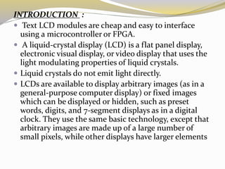
- 11. Verilog code : module Lcd_Display (clk, lcd_rs, lcd_rw, lcd_e, lcd_4, lcd_5, lcd_6, lcd_7); parameter n = 27; parameter k = 17; (* LOC="E12" *) input clk; // synthesis attribute PERIOD clk "100.0 MHz" reg [n-1:0] count=0; reg lcd_busy=1; reg lcd_stb; reg [5:0] lcd_code; reg [6:0] lcd_stuff; (* LOC="Y14" *) output reg lcd_rs; (* LOC="W13" *) output reg lcd_rw; (* LOC="Y15" *) output reg lcd_7; (* LOC="AB16" *) output reg lcd_6; (* LOC="Y16" *) output reg lcd_5;
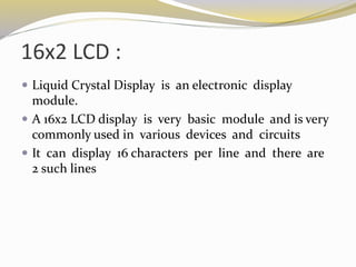
- 12. (* LOC="AA12" *) output reg lcd_4; (* LOC="AB4" *) output reg lcd_e; always @ (posedge clk) begin count <= count + 1; case (count[k+7:k+2]) 0: lcd_code <= 6'b000010; // function set 1: lcd_code <= 6'b000010; 2: lcd_code <= 6'b001100; 3: lcd_code <= 6'b000000; // display on/off control 4: lcd_code <= 6'b001100; 5: lcd_code <= 6'b000000; // display clear 6: lcd_code <= 6'b000001; 7: lcd_code <= 6'b000000; // entry mode set 8: lcd_code <= 6'b000110; 9: lcd_code <= 6'h24; // H 10: lcd_code <= 6'h28; 11: lcd_code <= 6'h26; // e 12: lcd_code <= 6'h25;
- 13. 13: lcd_code <= 6'h26; // l 14: lcd_code <= 6'h2C; 15: lcd_code <= 6'h26; // l 16: lcd_code <= 6'h2C; 17: lcd_code <= 6'h26; // o 18: lcd_code <= 6'h2F; 19: lcd_code <= 6'h22; // 20: lcd_code <= 6'h20; 21: lcd_code <= 6'h25; // W 22: lcd_code <= 6'h27; 23: lcd_code <= 6'h26; // o 24: lcd_code <= 6'h2F; 25: lcd_code <= 6'h27; // r 26: lcd_code <= 6'h22; 27: lcd_code <= 6'h26; // l 28: lcd_code <= 6'h2C; 29: lcd_code <= 6'h26; // d
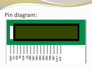
- 14. 30: lcd_code <= 6'h24; 31: lcd_code <= 6'h22; // ! 32: lcd_code <= 6'h21; default: lcd_code <= 6'b010000; endcase if (lcd_rw) lcd_busy <= 0; lcd_stb <= ^count[k+1:k+0] & ~lcd_rw & lcd_busy; // clkrate / 2^(k+2) lcd_stuff <= {lcd_stb,lcd_code}; {lcd_e,lcd_rs,lcd_rw,lcd_7,lcd_6,lcd_5,lcd_4} <= lcd_stuff; end endmodule
- 17. SYNTHESIS RESULT : UCF Generated # PlanAhead Generated physical constraints NET "clk" LOC = E12; NET "lcd_4" LOC = AA12; NET "lcd_5" LOC = Y16; NET "lcd_6" LOC = AB16; NET "lcd_7" LOC = Y15; NET "lcd_e" LOC = AB4; NET "lcd_rs" LOC = Y14; NET "lcd_rw" LOC = W13;
- 18. RTL SCHEMATIC:
- 19. Design Summary :
- 21. CONCLUSION : In this project behavioural level hardware descriptive language Verilog is used. Verification of the designed RTL code using simulation techniques, synthesis of RTL code to obtain gate level netlist using Xilinx ISE tool was successfully designed and implemented using Verilog and Xilinx Spatan-300AN Field Programmable Gate Array. Finally we were able to display “HELLO WORLD” on the LCD of FPGA board using interfacing.
- 22. Applications: Aero Space and Defence Medical Electronics Wired and Wireless comm. High performance computing Scientific instruments Video and image processing