SlideShare a Scribd company logo
Lecture 7

We must transform data into signals to send them from one place to another. Data stored
in the computer is in the form of 0’s and 1’s i.e. data is digital. To be carried from one
place to another, data are usually converted to digital signals. In which form to convert is
actually dependent upon the medium.

Q) What if the underlying medium is analog?
Answer: An analog medium can only carry analog signals, so we need to convert digital
data stored in computer into digital signal, the process of converting (digital data to
analog signal) is called as modulating a digital signal(as discussed below). We will
discuss later about modulation and how it is done.

Q) What if the underlying medium is digital?
Answer: Answer is quite similar to previous one, and with the same justification. Since
digital medium can only carry digital signals, we need to convert digital data stored in
computer into digital signal. The process of converting (digital data to digital signal) is
called as encoding. We will discuss later about encoding how it is done.

We talked about modulating a digital signal or encoding a digital signal, both the
encoding or modulating happens at the source end, can you guess what happens at the
receive end? Obviously receiver has to convert the analog signal to digital data or digital
signal to digital data.

Sometimes we need to convert an analog signal into a digital signal for several reasons,
such as to decrease the effect of noise. This is called analog-to-digital conversion or
digitizing an analog signal.

Often an analog signal is sent over long distances using analog media. For example, voice
or music from a radio station, which is naturally an analog signal, is transmitted through
the air. However, the frequency of the voice or music is not appropriate for this kind of
transmission; the signal should be carried by a higher frequency signal. This is called as
analog-to-analog conversion or modulating an analog signal.
Various techniques for Digital-to-Digital encoding
    1. Unipolar encoding
               Binary Encoding
    2. Polar encoding
               Manchester encoding
               Differential Manchester encoding
    3. Bipolar encoding
               AMI (Alternate Mark Inversion
               B8ZS (Bipolar 8-Zero Substitution)
               HDB3 (High-Density Bipolar 3)
Various techniques for Analog-to-Digital conversion
      1. PCM (Pulse Code Modulation)
      2. DPCM (Differential Pulse Code Modulation)
      3. DM (Delta Modulation)


Various techniques for Digital-to-Analog conversion (Modulation of Digital Data)
      1. ASK (Amplitude Shift Keying)
      2. FSK (Frequency Shift Keying)
      3. PSK (Phase Shift Keying)
      4. QAM (Quadrature Amplitude Modulation)
      5.


Various techniques for Analog-to-Analog Conversion
      1. AM (Amplitude Modulation)
      2. FM (Frequency modulation)
      3. PM (Phase Modulation)
Digital-to-Digital encoding

Binary Encoding
       Binary Encoding is a type of Unipolar Encoding. Unipolar encoding uses only
one voltage level. In this encoding 1’s are encoded as positive value and 0’s are encoded
as negative value.

Manchester Encoding
         Manchester Encoding is a type of Polar Encoding. Polar encoding uses two
voltage levels (positive and negative). With Manchester Encoding each bit period is
divided into two equal intervals. A binary bit 1 is sent by having the voltage set high
during the first interval and low in the second one. A Binary bit 0 is just the reverse, i.e.
voltage set low during the first interval and high in the second interval. The advantage of
this scheme ensures that every bit period has a transition in the middle, making it easy for
the receiver to synchronize with the sender. A disadvantage of Manchester encoding is
that it requires twice the bandwidth.

Differential Manchester Encoding
        Differential Manchester Encoding is a type of Polar Encoding. Polar encoding
uses two voltage levels (positive and negative).Differential Manchester encoding is a
variation of basic Manchester encoding. In it, a 1 bit is indicated by the absence of a
transition at the start of the transition and a 0 bit is indicated by the presence of a
transition at the start of the interval. In both the cases, there is a transition in the middle.
The disadvantage of differential scheme requires more complex equipment to
implement but advantage is that it offers better noise immunity.

In both Manchester and Differential Manchester encoding, the transition at the middle
of the bit is used for both synchronization and bit representation
Analog to Digital Conversion

   PCM (Pulse Code Modulation)
           Pulse Code Modulation is a technique for converting analog signal to digital.
   For that first the analog signal is sampled using sampling theorem. According to
   sampling theorem, Maximum number of samples = 2 * fmax i.e. twice the highest
   frequency. Thus, number of samples into which an analog signal is divided, is
   decided through sampling theorem. After sampling, quantization is done.
   Quantization is a method of assigning integral values in a specific range to samples
   instances. Each value is translated into its seven (7) bit binary equivalent i.e. binary
   encoding. The eighth bit indicates the sign. The binary digits are then transformed
   into a digital signal using one of the digital-to-digital encoding techniques. So, in
   nutshell, PCM is actually made up of four separate processes
   1. PAM
   2. Quantization
   3. Binary encoding
   4. Digital-to-Digital encoding.


PAM (Pulse amplitude modulation) has some applications, but it is not used by itself in
data communication. However, it is the first step in another very popular conversion
method called PCM (pulse code modulation).
The graph above depicts quantization.


The diagram above and below depicts binary encoding.
According to the Nyquist theorem, the sampling rate must be at least 2 times the
highest frequency. So the number of samples will be twice the highest frequency.

PCM has its application in modern telephone system. Whatever, we speak is actually an
analog signal. To transmit, it must be converted into the digital signal, for that PCM is
used. The range of frequency of human voice is 0 to 4000 Hz. This means the maximum
number of samples that can be generate of our voice is 8000 samples/second or 125µsec
i.e. each sample is generated after 125µsec. At a lower sampling rate than this,
information will be lost and at a higher sampling rate than this, no extra information
would be gained. Now this is analog signal is quantized and encoded into 7 bit and 1 bit
for sign. This means that there are (27) 256 levels.

According to Nyquist theorem (which holds true for noiseless channel)
Maximum Channel Capacity=2*B log2V

Where channel capacity is data rate in bits/sec (we want to calculate)
B is bandwidth and V is number of levels.

B is 4000 Hz (4000-0)
V is 256

Substitute in above equation, we get
Channel capacity=64000 bits/sec.

In T1 line, currently being used in U.S for telephonic conversation, there are 24 channels,
and each channel carrying capacity is 64000 bits/sec. Thus total capacity of T1 Line is
24*64000 bits/sec, which is 1536000 approx. 1.544 * 106 bits/sec.

Thus each channel is carrying 8 bits (7 bits of data and 1 bit for sign). It means that whole
T1 line is carrying 8 * 24 = 192 bits) plus one extra bit for framing thus yielding 193 bits.
And these bits are carried every 125µsec.

Q) What sampling rate is needed for a signal with a bandwidth of 10,000 Hz (1000 to
11,000 Hz)?
Answer: The sampling rate must be twice the highest frequency in the signal:
Sampling rate = 2 x (11,000) = 22,000 samples/s

Q) A signal is sampled. Each sample requires at least 12 levels of precision (+0 to +5
and -0 to -5). How many bits should be sent for each sample? Calculate the Nyquist Rate
i.e. channel capacity of the medium with Band Width=4000 Hz
Answer: We need 4 bits; 1 bit for the sign and 3 bits for the value. A 3-bit value can
represent 23 = 8 levels (000 to 111), which is less than what we need. A 2-bit value is not
enough since 22 = 4. A 4-bit value is too much because 24 = 16, but we cannot settle fir 3-
bit also. So number of levels will be effectively 16 and 4 bits will be used to represent
them.

According to Nyquist theorem (which holds true for noiseless channel)
Maximum Channel Capacity=2*B log2V
Maximum Channel Capacity=2*4000* log2 16
Maximum Channel Capacity=32000 bps or 32 Kbps.
Q) A digital signal has a bit rate of 2000 bps. What is the duration of each bit (bit
interval)
Answer: The bit interval is the inverse of the bit rate.
Bit interval = 1/ 2000 s = 0.000500 s
= 0.000500 x 10⁶ ms = 500 ms


Q) Consider a noiseless channel with a bandwidth of 3000 Hz transmitting a signal with
two signal levels. What is the maximum bit rate?
Answer: The maximum bit rate can be calculated as
Bit Rate = 2 × 3000 × log2 2 = 6000 bps

Q) Consider the same noiseless channel, transmitting a signal with four signal levels.
What is the maximum bit rate?
Answer: Bit Rate = 2 x 3000 x log2 4 = 12,000 bps


Q) We want to digitize the human voice. What is the bit rate, assuming 8 bits per sample?
Answer: The human voice normally contains frequencies from 0 to 4000 Hz. Sampling
rate = 4000 x 2 = 8000 samples/s
Bit rate = sampling rate x number of bits per sample
= 8000 x 8 = 64,000 bps = 64 Kbps

Differential Pulse Code Modulation
       Differential Pulse Code Modulation consists of outputting not the digitized
amplitude, but the difference between the current value and the previous one. So in this
case only 5 bits instead of 7 bits solve the purpose of binary encoding. This way same
channel is able to carry more number of bits thus increasing the channel capacity and
obviously the efficiency also.

Delta Modulation
        A variation of the above method is delta modulation, which requires each sampled
value to differ from its predecessor by either +1 or -1. A single bit is transmitted, telling
whether the new sample is above or below the previous one. This technique is called
delta modulation.
Disadvantage of delta modulation is that, if the signal changes too fast, information is
lost.
Fig for Delta Modulation

Channel Capacity for a Noiseless Channel
                       Till now we have learnt the formulae for calculating the channel
capacity of a noiseless medium. If we take a practical situation, there is no noiseless
channel; there is always some noise that can cause damage to the transmitted signal.

Q) So if a signal in transit is damaged, what do you think is the actual data rate, is it
going to be greater than the noiseless channel or less than?
Answer: Obviously less than the noiseless channel, because effectively undamaged bits
that reach at the receive end are less now.

We will learn later in error control, what to do if receiver receives damaged packets or
frames.

So, Shannon gave the formulae for channel capacity for noiseless channel, which is as
follows
C = B log2 (1 + SNR)
Where
C is the channel capacity
B is Bandwidth
SNR is signal to noise ratio.

Q Consider an extremely noisy channel in which the value of the signal-to-noise ratio is
almost zero. Signal-to-noise ratio is zero means; the noise is so strong that the signal is
faint. Calculate the capacity for this channel?
Answer:
C = B log2 (1 + SNR) = B log2 (1 + 0)
        = B log2 (1) = B × 0 = 0

Q. A telephone line normally has a bandwidth of 3000 Hz (300 Hz to 3300 Hz). The
signal-to-noise ratio is usually 3162. Calculate the capacity for this channel?
Answer: C = B log2 (1 + SNR) = 3000 log2 (1 + 3162)
= 3000 log2 (3163)
C = 3000 × 11.62 = 34,860 bps
Q. We have a channel with a 1 MHz bandwidth. The SNR for this channel is 63; what is
the appropriate bit rate and signal level?
Answer: First, we use the Shannon formula to find our upper limit.
C = B log2 (1 + SNR) = 106 log2 (1 + 63) = 106 log2 (64) = 6 Mbps
Then we use the Nyquist formula to find the number of signal levels.
4 Mbps = 2 × 1 MHz × log2 L è L = 4

More Related Content

PDF
Digital transmission
PPTX
3. digital transmission fundamentals
PPT
4 signal encodingtechniques
PPTX
Review
PPT
PPT
Encoding1
PPT
1 PCM & Encoding
PPT
Digital Transmission
Digital transmission
3. digital transmission fundamentals
4 signal encodingtechniques
Review
Encoding1
1 PCM & Encoding
Digital Transmission

What's hot (20)

PDF
A_law_and_Microlaw_companding
PPTX
Pcm transmitter and receiver
PPT
Pulse code modulation
PPT
Audio and video compression
PDF
Companding & Pulse Code Modulation
PPTX
Presentation ct
PPT
1432.encoding concepts
PPT
PPT
Lecture3 signal encoding_in_wireless
PDF
Dccn - Digital Transmission
PPT
L 1 5 sampling quantizing encoding pcm
PPTX
Digital communications 1
PPT
Pulse code mod
PDF
Dc ch05 : signal encoding techniques
PPTX
Unit i-pcm-vsh
DOC
Pulse code modulation and Quantization
PPTX
Digital Communication Techniques
PPTX
Pulse Code Modulation
PPTX
Wireless digital communication and coding techniques new
A_law_and_Microlaw_companding
Pcm transmitter and receiver
Pulse code modulation
Audio and video compression
Companding & Pulse Code Modulation
Presentation ct
1432.encoding concepts
Lecture3 signal encoding_in_wireless
Dccn - Digital Transmission
L 1 5 sampling quantizing encoding pcm
Digital communications 1
Pulse code mod
Dc ch05 : signal encoding techniques
Unit i-pcm-vsh
Pulse code modulation and Quantization
Digital Communication Techniques
Pulse Code Modulation
Wireless digital communication and coding techniques new
Ad

Viewers also liked (18)

PDF
Java script browser objects 1
 
PPSX
Pollock Expresionismo Abstracto
PPT
Week32
 
DOC
Lecture3layered archi
 
DOC
Css 1
 
PPT
What Do They Have in Common?
DOC
Lecture4 isoosi
 
PPT
Ch03
 
PDF
Ip protocol
 
PPT
Tribute To Dr.King
PPT
Reggaeton origin
PPT
The Second America
PDF
Java script browser objects 2
 
DOC
Lecture8 digitaltoanalogconversion
 
PPT
Culture & Diversity It Exists All Around Our World
DOC
Html basics 9 meta background
 
PPSX
Pollock Expresionismo Abstracto
PPT
Week31
 
Java script browser objects 1
 
Pollock Expresionismo Abstracto
Week32
 
Lecture3layered archi
 
Css 1
 
What Do They Have in Common?
Lecture4 isoosi
 
Ch03
 
Ip protocol
 
Tribute To Dr.King
Reggaeton origin
The Second America
Java script browser objects 2
 
Lecture8 digitaltoanalogconversion
 
Culture & Diversity It Exists All Around Our World
Html basics 9 meta background
 
Pollock Expresionismo Abstracto
Week31
 
Ad

Similar to Lecture7 encodingmodulation (20)

PPT
Data Encoding
PPTX
Introductionto Digitalcommunications and baseband modulation techniques
PPT
TeleCom Lecture 07.ppt
PPT
Introduction to communication system lecture4
PPTX
Transmisi Analog_24.pptx for lectured note
PPT
359484366-LECTURE-4-Analog-to-Digital-Conversion-ppt.ppt
PPT
Encoding and Modulating Data Signal from analog to digital and from digital t...
PPT
Ch4 1 Data communication and networking by neha g. kurale
PDF
PCM pulse code modulation.pdf
PPTX
Pulse code modulation (PCM)
PPT
PCM and delta modulation.ppt
PPT
analog_digital convers vvvvvvion1.ppt
PDF
DCOM Viva Questions FOR THIRD YEAR STUDENTS.pdf
PPTX
digital communication and Digital pulse Modulation.pptx
ODP
komdat5
PPT
Ch4 2 v1
PPT
DIGITAL TRANSMISSION
PPT
Analog-to-Digital-Conversion-10032025-081456am.ppt
PPT
ch4_2_v1.ppt111111111111111111111111111111
PDF
24071 digitalcommunication
Data Encoding
Introductionto Digitalcommunications and baseband modulation techniques
TeleCom Lecture 07.ppt
Introduction to communication system lecture4
Transmisi Analog_24.pptx for lectured note
359484366-LECTURE-4-Analog-to-Digital-Conversion-ppt.ppt
Encoding and Modulating Data Signal from analog to digital and from digital t...
Ch4 1 Data communication and networking by neha g. kurale
PCM pulse code modulation.pdf
Pulse code modulation (PCM)
PCM and delta modulation.ppt
analog_digital convers vvvvvvion1.ppt
DCOM Viva Questions FOR THIRD YEAR STUDENTS.pdf
digital communication and Digital pulse Modulation.pptx
komdat5
Ch4 2 v1
DIGITAL TRANSMISSION
Analog-to-Digital-Conversion-10032025-081456am.ppt
ch4_2_v1.ppt111111111111111111111111111111
24071 digitalcommunication

More from H K (20)

PDF
Assignment4
 
DOCX
Assignment3
 
PDF
Induction
 
PDF
Solution3
 
PDF
Solution2
 
DOCX
Mid-
 
PDF
Assignment4
 
PDF
Assignment4
 
PDF
Dm assignment3
 
PPT
Proof
 
PDF
Resolution
 
DOCX
Assignment description
 
PDF
Dm assignment2
 
PDF
Set
 
PDF
Dm assignment1
 
PPTX
Logic
 
DOCX
Introduction
 
PDF
Assignment 2 sol
 
PDF
Assignment sw solution
 
PDF
Violinphoenix
 
Assignment4
 
Assignment3
 
Induction
 
Solution3
 
Solution2
 
Mid-
 
Assignment4
 
Assignment4
 
Dm assignment3
 
Proof
 
Resolution
 
Assignment description
 
Dm assignment2
 
Set
 
Dm assignment1
 
Logic
 
Introduction
 
Assignment 2 sol
 
Assignment sw solution
 
Violinphoenix
 

Recently uploaded (20)

PPTX
A Presentation on Artificial Intelligence
PDF
gpt5_lecture_notes_comprehensive_20250812015547.pdf
PDF
Building Integrated photovoltaic BIPV_UPV.pdf
PDF
Optimiser vos workloads AI/ML sur Amazon EC2 et AWS Graviton
PPTX
ACSFv1EN-58255 AWS Academy Cloud Security Foundations.pptx
PDF
Assigned Numbers - 2025 - Bluetooth® Document
PDF
Peak of Data & AI Encore- AI for Metadata and Smarter Workflows
PPTX
20250228 LYD VKU AI Blended-Learning.pptx
PPTX
sap open course for s4hana steps from ECC to s4
PDF
Unlocking AI with Model Context Protocol (MCP)
PPTX
KOM of Painting work and Equipment Insulation REV00 update 25-dec.pptx
PDF
7 ChatGPT Prompts to Help You Define Your Ideal Customer Profile.pdf
PPTX
Big Data Technologies - Introduction.pptx
PPTX
Programs and apps: productivity, graphics, security and other tools
PDF
Review of recent advances in non-invasive hemoglobin estimation
PDF
Empathic Computing: Creating Shared Understanding
PDF
Blue Purple Modern Animated Computer Science Presentation.pdf.pdf
PDF
Approach and Philosophy of On baking technology
PPTX
Digital-Transformation-Roadmap-for-Companies.pptx
PDF
Reach Out and Touch Someone: Haptics and Empathic Computing
A Presentation on Artificial Intelligence
gpt5_lecture_notes_comprehensive_20250812015547.pdf
Building Integrated photovoltaic BIPV_UPV.pdf
Optimiser vos workloads AI/ML sur Amazon EC2 et AWS Graviton
ACSFv1EN-58255 AWS Academy Cloud Security Foundations.pptx
Assigned Numbers - 2025 - Bluetooth® Document
Peak of Data & AI Encore- AI for Metadata and Smarter Workflows
20250228 LYD VKU AI Blended-Learning.pptx
sap open course for s4hana steps from ECC to s4
Unlocking AI with Model Context Protocol (MCP)
KOM of Painting work and Equipment Insulation REV00 update 25-dec.pptx
7 ChatGPT Prompts to Help You Define Your Ideal Customer Profile.pdf
Big Data Technologies - Introduction.pptx
Programs and apps: productivity, graphics, security and other tools
Review of recent advances in non-invasive hemoglobin estimation
Empathic Computing: Creating Shared Understanding
Blue Purple Modern Animated Computer Science Presentation.pdf.pdf
Approach and Philosophy of On baking technology
Digital-Transformation-Roadmap-for-Companies.pptx
Reach Out and Touch Someone: Haptics and Empathic Computing

Lecture7 encodingmodulation

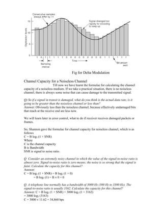
  • 1. Lecture 7 We must transform data into signals to send them from one place to another. Data stored in the computer is in the form of 0’s and 1’s i.e. data is digital. To be carried from one place to another, data are usually converted to digital signals. In which form to convert is actually dependent upon the medium. Q) What if the underlying medium is analog? Answer: An analog medium can only carry analog signals, so we need to convert digital data stored in computer into digital signal, the process of converting (digital data to analog signal) is called as modulating a digital signal(as discussed below). We will discuss later about modulation and how it is done. Q) What if the underlying medium is digital? Answer: Answer is quite similar to previous one, and with the same justification. Since digital medium can only carry digital signals, we need to convert digital data stored in computer into digital signal. The process of converting (digital data to digital signal) is called as encoding. We will discuss later about encoding how it is done. We talked about modulating a digital signal or encoding a digital signal, both the encoding or modulating happens at the source end, can you guess what happens at the receive end? Obviously receiver has to convert the analog signal to digital data or digital signal to digital data. Sometimes we need to convert an analog signal into a digital signal for several reasons, such as to decrease the effect of noise. This is called analog-to-digital conversion or digitizing an analog signal. Often an analog signal is sent over long distances using analog media. For example, voice or music from a radio station, which is naturally an analog signal, is transmitted through the air. However, the frequency of the voice or music is not appropriate for this kind of transmission; the signal should be carried by a higher frequency signal. This is called as analog-to-analog conversion or modulating an analog signal. Various techniques for Digital-to-Digital encoding 1. Unipolar encoding Binary Encoding 2. Polar encoding Manchester encoding Differential Manchester encoding 3. Bipolar encoding AMI (Alternate Mark Inversion B8ZS (Bipolar 8-Zero Substitution) HDB3 (High-Density Bipolar 3)
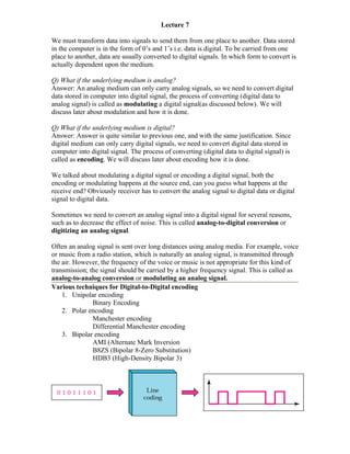
  • 2. Various techniques for Analog-to-Digital conversion 1. PCM (Pulse Code Modulation) 2. DPCM (Differential Pulse Code Modulation) 3. DM (Delta Modulation) Various techniques for Digital-to-Analog conversion (Modulation of Digital Data) 1. ASK (Amplitude Shift Keying) 2. FSK (Frequency Shift Keying) 3. PSK (Phase Shift Keying) 4. QAM (Quadrature Amplitude Modulation) 5. Various techniques for Analog-to-Analog Conversion 1. AM (Amplitude Modulation) 2. FM (Frequency modulation) 3. PM (Phase Modulation) Digital-to-Digital encoding Binary Encoding Binary Encoding is a type of Unipolar Encoding. Unipolar encoding uses only one voltage level. In this encoding 1’s are encoded as positive value and 0’s are encoded as negative value. Manchester Encoding Manchester Encoding is a type of Polar Encoding. Polar encoding uses two voltage levels (positive and negative). With Manchester Encoding each bit period is divided into two equal intervals. A binary bit 1 is sent by having the voltage set high during the first interval and low in the second one. A Binary bit 0 is just the reverse, i.e. voltage set low during the first interval and high in the second interval. The advantage of this scheme ensures that every bit period has a transition in the middle, making it easy for the receiver to synchronize with the sender. A disadvantage of Manchester encoding is that it requires twice the bandwidth. Differential Manchester Encoding Differential Manchester Encoding is a type of Polar Encoding. Polar encoding uses two voltage levels (positive and negative).Differential Manchester encoding is a variation of basic Manchester encoding. In it, a 1 bit is indicated by the absence of a transition at the start of the transition and a 0 bit is indicated by the presence of a transition at the start of the interval. In both the cases, there is a transition in the middle. The disadvantage of differential scheme requires more complex equipment to implement but advantage is that it offers better noise immunity. In both Manchester and Differential Manchester encoding, the transition at the middle of the bit is used for both synchronization and bit representation
  • 3. Analog to Digital Conversion PCM (Pulse Code Modulation) Pulse Code Modulation is a technique for converting analog signal to digital. For that first the analog signal is sampled using sampling theorem. According to sampling theorem, Maximum number of samples = 2 * fmax i.e. twice the highest frequency. Thus, number of samples into which an analog signal is divided, is decided through sampling theorem. After sampling, quantization is done. Quantization is a method of assigning integral values in a specific range to samples instances. Each value is translated into its seven (7) bit binary equivalent i.e. binary encoding. The eighth bit indicates the sign. The binary digits are then transformed into a digital signal using one of the digital-to-digital encoding techniques. So, in nutshell, PCM is actually made up of four separate processes 1. PAM 2. Quantization 3. Binary encoding 4. Digital-to-Digital encoding. PAM (Pulse amplitude modulation) has some applications, but it is not used by itself in data communication. However, it is the first step in another very popular conversion method called PCM (pulse code modulation).
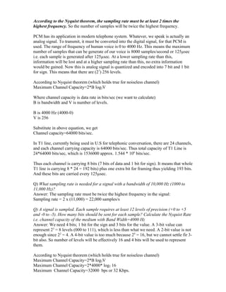
  • 4. The graph above depicts quantization. The diagram above and below depicts binary encoding.
  • 5. According to the Nyquist theorem, the sampling rate must be at least 2 times the highest frequency. So the number of samples will be twice the highest frequency. PCM has its application in modern telephone system. Whatever, we speak is actually an analog signal. To transmit, it must be converted into the digital signal, for that PCM is used. The range of frequency of human voice is 0 to 4000 Hz. This means the maximum number of samples that can be generate of our voice is 8000 samples/second or 125µsec i.e. each sample is generated after 125µsec. At a lower sampling rate than this, information will be lost and at a higher sampling rate than this, no extra information would be gained. Now this is analog signal is quantized and encoded into 7 bit and 1 bit for sign. This means that there are (27) 256 levels. According to Nyquist theorem (which holds true for noiseless channel) Maximum Channel Capacity=2*B log2V Where channel capacity is data rate in bits/sec (we want to calculate) B is bandwidth and V is number of levels. B is 4000 Hz (4000-0) V is 256 Substitute in above equation, we get Channel capacity=64000 bits/sec. In T1 line, currently being used in U.S for telephonic conversation, there are 24 channels, and each channel carrying capacity is 64000 bits/sec. Thus total capacity of T1 Line is 24*64000 bits/sec, which is 1536000 approx. 1.544 * 106 bits/sec. Thus each channel is carrying 8 bits (7 bits of data and 1 bit for sign). It means that whole T1 line is carrying 8 * 24 = 192 bits) plus one extra bit for framing thus yielding 193 bits. And these bits are carried every 125µsec. Q) What sampling rate is needed for a signal with a bandwidth of 10,000 Hz (1000 to 11,000 Hz)? Answer: The sampling rate must be twice the highest frequency in the signal: Sampling rate = 2 x (11,000) = 22,000 samples/s Q) A signal is sampled. Each sample requires at least 12 levels of precision (+0 to +5 and -0 to -5). How many bits should be sent for each sample? Calculate the Nyquist Rate i.e. channel capacity of the medium with Band Width=4000 Hz Answer: We need 4 bits; 1 bit for the sign and 3 bits for the value. A 3-bit value can represent 23 = 8 levels (000 to 111), which is less than what we need. A 2-bit value is not enough since 22 = 4. A 4-bit value is too much because 24 = 16, but we cannot settle fir 3- bit also. So number of levels will be effectively 16 and 4 bits will be used to represent them. According to Nyquist theorem (which holds true for noiseless channel) Maximum Channel Capacity=2*B log2V Maximum Channel Capacity=2*4000* log2 16 Maximum Channel Capacity=32000 bps or 32 Kbps.
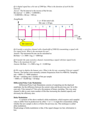
  • 6. Q) A digital signal has a bit rate of 2000 bps. What is the duration of each bit (bit interval) Answer: The bit interval is the inverse of the bit rate. Bit interval = 1/ 2000 s = 0.000500 s = 0.000500 x 10⁶ ms = 500 ms Q) Consider a noiseless channel with a bandwidth of 3000 Hz transmitting a signal with two signal levels. What is the maximum bit rate? Answer: The maximum bit rate can be calculated as Bit Rate = 2 × 3000 × log2 2 = 6000 bps Q) Consider the same noiseless channel, transmitting a signal with four signal levels. What is the maximum bit rate? Answer: Bit Rate = 2 x 3000 x log2 4 = 12,000 bps Q) We want to digitize the human voice. What is the bit rate, assuming 8 bits per sample? Answer: The human voice normally contains frequencies from 0 to 4000 Hz. Sampling rate = 4000 x 2 = 8000 samples/s Bit rate = sampling rate x number of bits per sample = 8000 x 8 = 64,000 bps = 64 Kbps Differential Pulse Code Modulation Differential Pulse Code Modulation consists of outputting not the digitized amplitude, but the difference between the current value and the previous one. So in this case only 5 bits instead of 7 bits solve the purpose of binary encoding. This way same channel is able to carry more number of bits thus increasing the channel capacity and obviously the efficiency also. Delta Modulation A variation of the above method is delta modulation, which requires each sampled value to differ from its predecessor by either +1 or -1. A single bit is transmitted, telling whether the new sample is above or below the previous one. This technique is called delta modulation. Disadvantage of delta modulation is that, if the signal changes too fast, information is lost.
  • 7. Fig for Delta Modulation Channel Capacity for a Noiseless Channel Till now we have learnt the formulae for calculating the channel capacity of a noiseless medium. If we take a practical situation, there is no noiseless channel; there is always some noise that can cause damage to the transmitted signal. Q) So if a signal in transit is damaged, what do you think is the actual data rate, is it going to be greater than the noiseless channel or less than? Answer: Obviously less than the noiseless channel, because effectively undamaged bits that reach at the receive end are less now. We will learn later in error control, what to do if receiver receives damaged packets or frames. So, Shannon gave the formulae for channel capacity for noiseless channel, which is as follows C = B log2 (1 + SNR) Where C is the channel capacity B is Bandwidth SNR is signal to noise ratio. Q Consider an extremely noisy channel in which the value of the signal-to-noise ratio is almost zero. Signal-to-noise ratio is zero means; the noise is so strong that the signal is faint. Calculate the capacity for this channel? Answer: C = B log2 (1 + SNR) = B log2 (1 + 0) = B log2 (1) = B × 0 = 0 Q. A telephone line normally has a bandwidth of 3000 Hz (300 Hz to 3300 Hz). The signal-to-noise ratio is usually 3162. Calculate the capacity for this channel? Answer: C = B log2 (1 + SNR) = 3000 log2 (1 + 3162) = 3000 log2 (3163) C = 3000 × 11.62 = 34,860 bps
  • 8. Q. We have a channel with a 1 MHz bandwidth. The SNR for this channel is 63; what is the appropriate bit rate and signal level? Answer: First, we use the Shannon formula to find our upper limit. C = B log2 (1 + SNR) = 106 log2 (1 + 63) = 106 log2 (64) = 6 Mbps Then we use the Nyquist formula to find the number of signal levels. 4 Mbps = 2 × 1 MHz × log2 L è L = 4