SlideShare a Scribd company logo
3
Most read
9
Most read
10
Most read
Operation of Reciprocating Pump
FLUID POWER ENGINEERING
introduction
• If mechanical energy is converted into
hydraulic energy by taking water inside the
cylinder in which piston is reciprocating, which
exerts thrust force on the liquid is known as
reciprocating pump.
• A reciprocating pump is a class of positive-
displacement pumps which includes the piston
pump, plunger pump and diaphragm pump.
• The given pump is single acting single cylinder
pump with air vessel. It can be used for less
discharge at higher heads. Priming is not
required because it is a positive displacement
pump. Reciprocating pumps are used in
pumping water in hilly areas

Components of reciprocating pumps
• Main parts of reciprocating pump
• A cylinder with a piston, piston rod
and cranka
• Suction pipe
• Delivery pipe
• Suction pipe
• Delivery pipe
Classification of reciprocating pump
• Based on contact of liquid
Single acting
Double acting
• Based on reciprocating member
Piston pump
Plunger pump
Bucket pump
• Based on number of cylinder
Single cylinder
Multi cylinder
• Discharge through a single acting reciprocating pump.
• D=diameter of the cylinder
• A=cross section area of the Piston or cylinder
• r=radius of the Crank
• N=RPM of Crank
• L=length of stroke = 2 x r
• hs=equals to suction head or height of excess of the cylinder from water surface in
sump
• hd=delivery head or height of the delivery outlet above the cylinder axis
• Discharge of water in one revolution = Area x Length of stroke
= A x L
• Number of revolution per second =N/60
• Discharge of pump per second
Q =Discharge in one second x number of revolution per second
= A x L x N/60 = ALN/60 m3/sec
Double acting reciprocating pump
• In case of double-acting pump, the water is
acting on both sides of the piston as shown in
figure. Thus, we require two suction pipes and
two delivery pipes for double-acting pump.
• When there is a Suction stroke on one side of the
piston, there is at the same time a delivery stroke on
the other side of the piston. Thus for one complete
revolution of the crank there are two delivery
strokes and water is delivered to the pipes by the
pump during these two delivery strokes.
Discharge through double acting reciprocating pump
• Discharge = water discharge + water discharge
• in forward stroke in reverse stroke
= ᴫD2L/4 + ᴫ(D2 – d2) L/4ᴫ
= ᴫD2L/4 + ᴫD2L/4 - ᴫd2L/4
= ᴫ (2D2 - d2) L/4 m3/cycle
= ᴫ (2D2 - d2) L/4 * N/60 m3/second
Q = 2ALN/60 ( NEGLECTING d2 )
Work done by double acting reciprocating pump
• Work done/second = weight of water delivered per second * head
lifted
= ρgQ * (hs + hd)
W.D./SECOND = 2ρgALN * (hs + hd) / 60
Slip of the reciprocating pump
• The difference of theoretical discharge and actual discharge is known
as slip of the pump, mathematically
  
















d
rh
act
d
th
act
th
actth
actth
C
Q
Q
C
Q
Q
Q
QQ
QQ
.......1001
1001100slipPercentage
Slip
Indicator Diagram
• The pressure variation in the cylinder
during a cycle consisting of one
revolution of the crank. When
represented in a diagram is termed as
indicator diagram.
• Figure represents an ideal diagram,
assuming no other effects are involved
except the suction and delivery
pressures.
• Point 1 represents the condition as the
piston has just started moving during
the suction stroke.
Indicator Diagram
• 1-2represents the suction stroke and the pressure in the cylinder is the
suction pressure below the atmospheric pressure.
• The point 3 represents the condition just as the piston has started
moving when the pressure increases to the delivery pressure. Along 3-
4 representing the delivery stroke the pressure remains constant.
• The area enclosed represents the work done during a crank revolution
to some scale
 
 
60
ds
ds
hhgLAN
p
hhgQp





Operation of reciprocating pump

More Related Content

PPTX
Reciprocating Pump
PPT
Basics Fundamentals and working Principle of Centrifugal Pump.
PPTX
Centrifugal Pumps
PPTX
centrifugal pump ppt
PPTX
PPTX
Hydraulic Pumps
PDF
Positive Displacement Pumps
PPSX
Basic Mechanical Engineering- Hydraulic turbines
Reciprocating Pump
Basics Fundamentals and working Principle of Centrifugal Pump.
Centrifugal Pumps
centrifugal pump ppt
Hydraulic Pumps
Positive Displacement Pumps
Basic Mechanical Engineering- Hydraulic turbines

What's hot (20)

PDF
Hydraulic systems
PPTX
Draft tube
PPTX
Air compressors
PDF
The Working Principle of Submersible Pump
PDF
Impact of jet
PPT
Pump design presentation
PPTX
Head losses
PPTX
Flow through pipes
PPTX
Turbo machinery
PPTX
Centrifugal Pumps
PPT
Pumps and types of pumps
PPS
Positive Displacement Pumps - Basic Principle
PPTX
Introduction of pump
PPTX
Reciprocating Pumps
PPTX
CAVITATION IN CENTRIFUGAL PUMP
PPTX
Basics of pump
PDF
All You Need To Know About Cavitation In Centrifugal Pumps
PDF
Pumps Presentation.pdf
PPTX
Compressor and Types
Hydraulic systems
Draft tube
Air compressors
The Working Principle of Submersible Pump
Impact of jet
Pump design presentation
Head losses
Flow through pipes
Turbo machinery
Centrifugal Pumps
Pumps and types of pumps
Positive Displacement Pumps - Basic Principle
Introduction of pump
Reciprocating Pumps
CAVITATION IN CENTRIFUGAL PUMP
Basics of pump
All You Need To Know About Cavitation In Centrifugal Pumps
Pumps Presentation.pdf
Compressor and Types
Ad

Similar to Operation of reciprocating pump (20)

PPT
Mechanical engineering resiprocating_pumps.ppt
PPT
Resiprocating_pumpps on description ppt
PPT
5.resiprocating pumps
PPT
5.resiprocating pumps
PPT
5.resiprocating_pumps.ppt5.resiprocating_pumps.ppt
PPT
FMM PUMP.ppt 5.resiprocating_pumps.ppt5.resiprocating_pumps.ppt
PPTX
classification of pump.pptx
PDF
Power Point Presentation on Reciprocating Pumps
PPT
FM RECIPROCATING PUMP
PPTX
working ppt of a Reciprocating Pump.pptx
PPTX
Resiprocating pump
PPTX
Receprocating pump
PPTX
Centrifugal & reciprocating pumps
PDF
4 pump 03 reciprocating pump
PPT
Pumps & valves
DOCX
Reciprocating pump pdf
PPTX
Fluid Machinery 1st class today.pptxcccc
PPTX
Pump eme
PPTX
Reciprocating pump(1) (2)
PPTX
Rceprocating pump
Mechanical engineering resiprocating_pumps.ppt
Resiprocating_pumpps on description ppt
5.resiprocating pumps
5.resiprocating_pumps.ppt5.resiprocating_pumps.ppt
FMM PUMP.ppt 5.resiprocating_pumps.ppt5.resiprocating_pumps.ppt
classification of pump.pptx
Power Point Presentation on Reciprocating Pumps
FM RECIPROCATING PUMP
working ppt of a Reciprocating Pump.pptx
Resiprocating pump
Receprocating pump
Centrifugal & reciprocating pumps
4 pump 03 reciprocating pump
Pumps & valves
Reciprocating pump pdf
Fluid Machinery 1st class today.pptxcccc
Pump eme
Reciprocating pump(1) (2)
Rceprocating pump
Ad

More from vaibhav tailor (20)

PPTX
Numerical integration;Gaussian integration one point, two point and three poi...
PPTX
Flow of viscous fluid through circular pipe
PPTX
Series solutions at ordinary point and regular singular point
PPTX
Recapitulation of carnot,otto and diesel cycle, dual cycle,comparison of ott...
PPTX
Gibbs phase rule and lever rule
PPTX
PPTX
Cases of eccentric loading in bolted joints
PPTX
Flow through pipes
PPTX
The taylor hobson talysurf surface roughness tester
DOC
Sony pictures crippled by gop hackers, 2014 cs ala
PPTX
Physical significance of non dimensional numbers
PPTX
Intro to production management and plant layout
PPTX
Concentric springs, surge phenomenon in spring, helical torsion, spiral spring
PPTX
Classification of clutches, torque transmission capacity, considerations for ...
PPT
USM Ultra Sonic Machinig
PPT
Refrigerant condenser and its types
PPTX
Surface Hardening of Steel
PPTX
Milling cutters
PPTX
Laplace transform & fourier series
PPTX
Graphical interfacing standards
Numerical integration;Gaussian integration one point, two point and three poi...
Flow of viscous fluid through circular pipe
Series solutions at ordinary point and regular singular point
Recapitulation of carnot,otto and diesel cycle, dual cycle,comparison of ott...
Gibbs phase rule and lever rule
Cases of eccentric loading in bolted joints
Flow through pipes
The taylor hobson talysurf surface roughness tester
Sony pictures crippled by gop hackers, 2014 cs ala
Physical significance of non dimensional numbers
Intro to production management and plant layout
Concentric springs, surge phenomenon in spring, helical torsion, spiral spring
Classification of clutches, torque transmission capacity, considerations for ...
USM Ultra Sonic Machinig
Refrigerant condenser and its types
Surface Hardening of Steel
Milling cutters
Laplace transform & fourier series
Graphical interfacing standards

Recently uploaded (20)

PPTX
Sustainable Sites - Green Building Construction
PPT
Mechanical Engineering MATERIALS Selection
DOCX
ASol_English-Language-Literature-Set-1-27-02-2023-converted.docx
PPTX
Current and future trends in Computer Vision.pptx
PDF
Model Code of Practice - Construction Work - 21102022 .pdf
PPTX
Internet of Things (IOT) - A guide to understanding
PPTX
Lecture Notes Electrical Wiring System Components
PPTX
FINAL REVIEW FOR COPD DIANOSIS FOR PULMONARY DISEASE.pptx
PDF
Operating System & Kernel Study Guide-1 - converted.pdf
PDF
composite construction of structures.pdf
DOCX
573137875-Attendance-Management-System-original
PPTX
Construction Project Organization Group 2.pptx
PPTX
UNIT 4 Total Quality Management .pptx
PPTX
Geodesy 1.pptx...............................................
PPTX
OOP with Java - Java Introduction (Basics)
PPT
Project quality management in manufacturing
PDF
PRIZ Academy - 9 Windows Thinking Where to Invest Today to Win Tomorrow.pdf
PDF
keyrequirementskkkkkkkkkkkkkkkkkkkkkkkkkkkkkkkkkkkkk
PDF
Embodied AI: Ushering in the Next Era of Intelligent Systems
PDF
July 2025 - Top 10 Read Articles in International Journal of Software Enginee...
Sustainable Sites - Green Building Construction
Mechanical Engineering MATERIALS Selection
ASol_English-Language-Literature-Set-1-27-02-2023-converted.docx
Current and future trends in Computer Vision.pptx
Model Code of Practice - Construction Work - 21102022 .pdf
Internet of Things (IOT) - A guide to understanding
Lecture Notes Electrical Wiring System Components
FINAL REVIEW FOR COPD DIANOSIS FOR PULMONARY DISEASE.pptx
Operating System & Kernel Study Guide-1 - converted.pdf
composite construction of structures.pdf
573137875-Attendance-Management-System-original
Construction Project Organization Group 2.pptx
UNIT 4 Total Quality Management .pptx
Geodesy 1.pptx...............................................
OOP with Java - Java Introduction (Basics)
Project quality management in manufacturing
PRIZ Academy - 9 Windows Thinking Where to Invest Today to Win Tomorrow.pdf
keyrequirementskkkkkkkkkkkkkkkkkkkkkkkkkkkkkkkkkkkkk
Embodied AI: Ushering in the Next Era of Intelligent Systems
July 2025 - Top 10 Read Articles in International Journal of Software Enginee...

Operation of reciprocating pump

  • 1. Operation of Reciprocating Pump FLUID POWER ENGINEERING
  • 2. introduction • If mechanical energy is converted into hydraulic energy by taking water inside the cylinder in which piston is reciprocating, which exerts thrust force on the liquid is known as reciprocating pump. • A reciprocating pump is a class of positive- displacement pumps which includes the piston pump, plunger pump and diaphragm pump. • The given pump is single acting single cylinder pump with air vessel. It can be used for less discharge at higher heads. Priming is not required because it is a positive displacement pump. Reciprocating pumps are used in pumping water in hilly areas 
  • 3. Components of reciprocating pumps • Main parts of reciprocating pump • A cylinder with a piston, piston rod and cranka • Suction pipe • Delivery pipe • Suction pipe • Delivery pipe
  • 4. Classification of reciprocating pump • Based on contact of liquid Single acting Double acting • Based on reciprocating member Piston pump Plunger pump Bucket pump • Based on number of cylinder Single cylinder Multi cylinder
  • 5. • Discharge through a single acting reciprocating pump. • D=diameter of the cylinder • A=cross section area of the Piston or cylinder • r=radius of the Crank • N=RPM of Crank • L=length of stroke = 2 x r • hs=equals to suction head or height of excess of the cylinder from water surface in sump • hd=delivery head or height of the delivery outlet above the cylinder axis • Discharge of water in one revolution = Area x Length of stroke = A x L • Number of revolution per second =N/60 • Discharge of pump per second Q =Discharge in one second x number of revolution per second = A x L x N/60 = ALN/60 m3/sec
  • 6. Double acting reciprocating pump • In case of double-acting pump, the water is acting on both sides of the piston as shown in figure. Thus, we require two suction pipes and two delivery pipes for double-acting pump. • When there is a Suction stroke on one side of the piston, there is at the same time a delivery stroke on the other side of the piston. Thus for one complete revolution of the crank there are two delivery strokes and water is delivered to the pipes by the pump during these two delivery strokes.
  • 7. Discharge through double acting reciprocating pump • Discharge = water discharge + water discharge • in forward stroke in reverse stroke = ᴫD2L/4 + ᴫ(D2 – d2) L/4ᴫ = ᴫD2L/4 + ᴫD2L/4 - ᴫd2L/4 = ᴫ (2D2 - d2) L/4 m3/cycle = ᴫ (2D2 - d2) L/4 * N/60 m3/second Q = 2ALN/60 ( NEGLECTING d2 ) Work done by double acting reciprocating pump • Work done/second = weight of water delivered per second * head lifted = ρgQ * (hs + hd) W.D./SECOND = 2ρgALN * (hs + hd) / 60
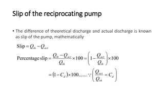
  • 8. Slip of the reciprocating pump • The difference of theoretical discharge and actual discharge is known as slip of the pump, mathematically                    d rh act d th act th actth actth C Q Q C Q Q Q QQ QQ .......1001 1001100slipPercentage Slip
  • 9. Indicator Diagram • The pressure variation in the cylinder during a cycle consisting of one revolution of the crank. When represented in a diagram is termed as indicator diagram. • Figure represents an ideal diagram, assuming no other effects are involved except the suction and delivery pressures. • Point 1 represents the condition as the piston has just started moving during the suction stroke.
  • 10. Indicator Diagram • 1-2represents the suction stroke and the pressure in the cylinder is the suction pressure below the atmospheric pressure. • The point 3 represents the condition just as the piston has started moving when the pressure increases to the delivery pressure. Along 3- 4 representing the delivery stroke the pressure remains constant. • The area enclosed represents the work done during a crank revolution to some scale     60 ds ds hhgLAN p hhgQp     