SlideShare a Scribd company logo
V.R.S. College of Engineering & Technology
(Reaccredited by NAAC and an ISO 9001:2008 Recertified Institution)
Arasur-607107, Villupuram District
Subject Name : Process Planning and Cost Estimation
Subject code : CME 396
Regulation : R-2021
Department : Mechanical
Year : III - Year
Semester : VI
UNIT - II
PROCESS PLANNING ACTIVITIES
SYLLABUS:
Process parameters calculation for various production processes- Selection jigs and fixture
selection of quality assurance methods - Set of documents for process planning-Economics of process
planning- case studies.
Part A
1. What is activity based costing? (AU N/D -2018)
Activity-based costing (ABC) is a costing methodology that identifies activities in an
organization and assigns the cost of each activity with resources to all products and services according
to the actual consumption by each. This model assigns more indirect costs (overhead) into direct costs
compared to conventional costing.
2. What are the main reasons for using jigs and fixtures? (AU N/D -2017) What factors are
considered in the selection of jigs and fixtures for manufacturing processes?(AU Apr/May 2024)
The main purpose of any work holding device is to position and hold a work piece in a
precise location while manufacturing operation is being performed.
Factors
1.Part Geometry and Complexity, 2. Accuracy and Tolerance Requirements,3. Manufacturing
Process Requirements
3. What are the most influential factors in terms of tool performance? (AU N/D-2017)
Factors affecting tool performance
 Cutting tool Materials
1
 Cutting tool Geometry
 Cutting fluids
4. What are the factors to be considered during the selection of a process?(AU N/D -2016)
 Quality of work to be completed
 Availability of equipments, tools and personnels
 Sequence in which operations will be performed on the raw material
 Standard time for each operation
5. Enumerate the documents required for process planning (AU N/D-2015)
 Product design and the engineering drawings pertaining to all the components of the product.
 Machining/Machinability Data Handbook Catalogues of various cutting tools and tool inserts.
 Specifications of various machine tools available in the shop/catalogues of machine tools in the
shop.
 Sizes of standard materials commercially available in the market. Machine Hr. cost of all
equipment available in the shop.
 Design Data Handbook.
 Charts of Limits, Fits & Tolerances.
 Tables showing tolerances and surface finish obtainable for different machining processes.
 Tables of standard cost.
 Table of allowances (such as Personal Allowance, Fatigue Allowance etc. in% of standard time
followed by the company.
6. State the parameters involved in material selection. Mention the importance of calculating process
parameters for various production process.(AU Apr/May 2024)
Functional requirements
 Reliability
 Service life durability
 Aesthetics and appearance
 Environmental Factors
 Compatibility with other materials during service
 Producibility or manufacturability
 Cost
7. What are the activities associated with process planning?
 Analyse the part requirements
 Determine operation sequence
 Select the equipment
 Calculate processing times
 Select inspection methods
 Estimate manufacturing cost
2
 Document process plan
 Communicate to manufacturing engineer
8. State the procedure to select cost optimal process(AU N/D-2011)
 Break even point
 Break even chart and Break even analysis
9. What is the difference between routing sheet and operations?
 A route sheet determines the sequence or order of arrangement of various departments in a facility.
Thus, a route sheet is a document which has information and data inputs and a step wise listing of
all the processes or transactions performed. It also contains details such as date and time, remarks,
log in/out, point of contact etc.
 Operation sheet is a list of operations has to be performed in a process without sequence.
10. What is the relation between tolerance and surface finish?(AU April/May-2017)
Components must fit together and function properly in a predicted dimension is defined as
tolerance, whereas surface finish is the depth of irregularities and vertical deviations of a surface resulting
from the manufacturing process used to produce it.
11. What is the purpose of a work holding device?
The main purpose of any work holding device is to position and hold a work piece in a precise
location while the manufacturing operation is being performed.
12. List the types of work holding devices.
 General work holding devices
 Vice
 Clamps Mandrels Chucks
 Specialist work holding devices Jigs
 Fixtures
13. What is meant by Statistical Quality Control (SQC)?
SQC is about employing inspection methodologies derived from statistical sampling theory
to ensure conformance to requirements.
14. List seven statistical tools of quality that are used in quality control
1. Flowchart
2. Cause and effect diagram
3. Check sheet
4. Scatter diagram
5. Histogram
6. Control chart
7. Pareto diagram
3
15. What is meant by break even analysis (BEA)?
BEA also known as cost volume profit analysis is the study of inter- relationships among a firms
sales, costs and operating profit at various levels of output.
16. What is fixed cost?
The fixed costs are the items of expenditure which remain more or less constant irrespective of the
volume of production. Some important items under fixed costs are depreciation of plant and machinery and
building, interest on capital, supervisory charges, cost of lighting, heating and cleaning the works, operator
charges, rent of building etc.
17. What is variable cost?
Variable costs are those items of expenditure which vary with the volume of production. Some
important items under variable costs are direct material cost, cost of power/fuel consumed, cost of tools
used, cost of consumable stores, repair and maintenance charges, storage charges, etc.
18. How to calculate hourly cost of running and maintenance of machines?
The hourly cost of running and maintenance of a machine has to be calculated before we an
calculate the total cost of any component requiring machining operations.
=
Fixed costs
machine life in hours
+Variable costs per hour
The cost of using a particular machine for one component is given by :
C=T ×R
where, C = Cost of using a particular machine for making one component.
T = Machine hours required to make one component.
R = Hourly rate of running and maintenance of machine.
19. Define production cost? (Apr/May-2017)(Nov/Dec-2019)
Production cost is the cost of manufacturing a product
20. Define prime cost? (Nov/Dec 2009)
 Prime cost is the combination of a manufactured product's costs of direct materials and direct
labor.
 In other words, prime cost refers to the direct production costs. Indirect manufacturing costs are
not part of prime cost.
PART_- B
1. Describe the basic method employed for the selection of cutting tools. (AU N/D 2017)
(i) Evaluation of process and machine selections-
Provided the selection of processes and machines is satisfactory, the range of tools that can be used
should be limited to those suitable for the processes and machines selected. Therefore, this limits
the initial list of possible suitable tooling.
4
(ii) Analysis of machining operations-
 A specific machine will carry out every operation required.
 Each machine tool to be used will have specific tool types to carry out certain operations.
 Therefore, this analysis should enable the identification of specific tool types for specific
operations.
(iii) Analysis of workpiece characteristics –
 The focus of the workpiece analysis is on the workpiece material and geometry and the capability
in terms of dimensional and geometric accuracy and surface finish.
 The analysis of the first two characteristics enables suitable tool materials and geometry (in terms
of size and shape) to be identified.
 The third characteristic allows the tool type and geometry to be refined further to suit the
operations.
(iv) Tooling analysis-
 Using the tooling data available, the general tooling specifications generated at the third stage can
be translated into a statement of tooling requirements for the job, that is, a tooling list.
 This will obviously reflect whatever tooling is actually available for the operations required.
(v) Selection of tooling –
 There are two routes that the tool selection can take at this point.
 If single-piece tooling is being used, then a suitable tool holder should be selected before fully
defining the tool geometry and material.
 However, if insert-type tooling is being used then the following steps should be followed:
1. Select clamping system;
2. Select tool holder type and Size;
3. Select insert shape;
4. Select insert size;
5. Determine tool edge dies;
6. Select insert type;
7. Select tool material.
 Once all of the above is completed, the machining parameters can be calculated. These will be the
speeds, feeds and machining times for each operation. All of the above factors will have a
significant influence on the determination of these parameters.
2. Explain the process planning procedure and List out the information required for process
planning. (AU Nov/Dec-2017) (Or)
What are the Set of documents required for process planning? (Or) Explain the steps involved in
process planning.
 Set of documents required for process planning
5
 Product design and the engineering drawings pertaining to all the components of the product. (i.e.,
components drawings, specifications and a bill of materials that defines how many of each
component go into the product).
 Machining/Machinability Data Handbook (Tables of cutting speeds, depth of cut, feeds for
different processes and for different work materials).
 Catalogues of various cutting tools and tool inserts.
 Specifications of various machine tools available in the shop/catalogues of machine tools in the
shop (speeds, feeds, capacity/power rating of motors, spindle size, table sizes etc.).
(i) Sizes of standard materials commercially available in the market.
(ii) Machine Hr. cost of all equipment available in the shop.
(iii) Design Data Handbook.
(iv) Charts of Limits, Fits & Tolerances.
(v) Tables showing tolerances and surface finish obtainable for different machining processes.
(vi) Tables of standard cost.
(vii) Table of allowances (such as Personal Allowance, Fatigue Allowance etc. in % of standard
time followed by the company).
(viii) Process plans of certain standard components such as shafts, bushings, flanges etc.
(ix) Handbooks (such as Tool Engineers Handbook, Design Data Handbook).
Steps in process planning
Required operations must be determined by examining the design data and employing basic machining
data such as:
1. Holes can be made conveniently on drilling machines.
2. Flat surfaces can be machined easily on milling machines.
3. Cylindrical parts can be made using lathe.
4. Design data can be obtained from the part-drawing or from the finished part design file from the
CAD system. The machines required for each operation must be determined. This selection
depends on knowledge of machine factors, such as availability of the machine, specifications of
machine tools available in the shop, accuracy grade of the m/c, table size, spindle size, Speed and
feed ranges available, torque, power, machining rate and other size limitations.
5. The required tools for each identified machine or process must be determined. For selection of
specialized tools knowledge and prior experience of process planner will be useful.
6. The optimum cutting parameters for each selected tool must be determined. These parameters
include cutting speed, feed rate, depth of cut, and type of coolant/lubricant to be used. This
determination depends on design data, such as work material, tool material, surface finish
specifications and behaviour of cutting tool. Again expertise knowledge and prior experience of
6
process planner and methods engineer will be useful in this regard. Machining data handbooks can
also be referred.
7. Finally an optimum combination of these machining processes must be determined. The best
process plan is the one which minimizes manufacturing time and cost. This provides a detailed
plan for the economical manufacturing of the part.
8. The results of each of these five basic steps can be seen in the final form of the process plan
3. What are the factors that influence process planning? Discuss. Explain the steps in process
selection with suitable example (AU N/D-2017)
Practices of Process Planning
The practices of process planning vary widely in modern industry, depending on such factors as :
 Type of product
 The equipment available, and
 The volume of production (i.e., production quantity)
The individual responsible for carrying out process planning / process analysis is the Process
Engineer also known as process planner, process analyst or methods engineer. To be effective on his or
her job, the process analyst must be familiar with material characteristics and manufacturing processes.
Knowledge of the nature, types, and properties of standard materials and new materials will
assist the process analyst in selecting the most appropriate process, equipment and methods for
manufacturing a particular product. The process analyst must also be familiar with engineering
drawings and product design.
Drawings provide the part configuration and the dimensional tolerances and specifications
that need to be met by the manufacturing process selected.
In addition, the process planner must be familiar with the operating characteristics and costs of
the production and tooling equipment, either available in the plant or to be purchased.
Process Planning starts with a careful examination of the drawing or design of the part. The
process planner must be able to analyze the engineering drawing and visualize the three dimensional
part configuration. The part configuration must then be analyzed to determine its basic geometric
components. Identifying these basic geometric elements assists the process planner in selecting the most
appropriate process to manufacture the product.
Process Selection
1. Consideration should be given to the following factors in selecting a particular process
2. Nature of part, including materials, tolerances, desired surface finish and operation required.
3. Method of fabrication including machining or assembling of similar parts or components.
4. Limitation of facilities including the plant and equipment available.
5. Possibility of likely product design changes to facilitate manufacturability or cost reduction.
7
6. In-plant and outside materials handling systems.
7. Inherent process to produce specified shape, surface, finish to give desired mechanical properties.
8. Available skill level of operators for the production. Sometimes the following additional factors
affect the selection of a particular process.
9. Proposed or anticipated production requirements, including volume requirements, production rates
and short- term or long- term production runs.
10. Total end-product costs.
11. Time available for tooling-up.
12. Materials receipt, storage, handling and transportation. Careful consideration of these factors will
result in the selection of the most appropriate process for the manufacture of a particular product.
Selection of an appropriate manufacturing process depends on many factors and requires
considerable knowledge, skill and competence of the process planner or process analyst.
Machine Selection
Product manufacturing requires tools and machines that can produce economically as well as
accurately. Economy depends to a large extent on the proper selection of the machine or process for the
job that will give a satisfactory finished product. The selection of the machine is influenced, in turn by
the quantity of items to be produced. Usually there is one machine best suited for a certain output.
In small lot or jobbing type manufacture, general purpose machines such as the lathe, drill press, and
milling machine may prove to be the best type since they areadoptable, have lower initial cost, require
less maintenance, and possess the flexibility to meet changing conditions in the shop. However, a
special purpose machine should be considered when large quantities of a standard product are to be
produced. A machine built for one type of work or operation, such as the grinding of a piston or the
machining of a cylinder head, will do the job well, quickly and at a low cost requiring only the service
of a semi-skilled operator.
Many of the special-purpose machines or tools differ from the usual standard type in that they have
built into them some of the skill of the operator. A simple bolt may be produced on either a lathe or an
automatic screw machine. The lathe operator must not only know how to make the bolt but must also be
sufficiently skilled to operate the lathe. On the automatic machine the sequence of operations and
movements of tools are controlled by cams and stops, and each item produced is identical with the
previous one.
This transfer of skill into the machine makes possible the use of less skillful operators, but it does
requires greater skill in supervision and maintenance. Often it is not economical to make a machine
completely automatic, as the cost may become prohibitive.
The selection of the best machine or process for a given product requires knowledge of all possible
production methods. Factors that must be considered are:
8
• Volume of production (Quantity to be produced) i.e., no. of components to be produced.
• Quality of finished product, and
• Advantages and disadvantages of the various types of equipment capable of doing the work.
Too much emphasis cannot be given to the fact that production can be by several methods, but
usually there is one way that is most economical.
Material selection
Material selection is done by the product designer considering the requirements of the parts designed
and the hardness, strength properties and other mechanical characteristics of the material. Cost and
availability of the material are also considered. Material should be strong enough and at the same time
manufacturing or producibility of the part using the given material and the process are also equally
important.
In the initial stages of design, the broad material groups such as ferrous or non-ferrous or other non-
metallic materials can be considered. At a later stage specific material in the group can be identified.
In certain products or components specific properties of materials such as fatigue strength, thermal
conductivity, electrical properties like conductivity, magnetic permeability and insulation resistance
may have to be considered.
Mention the importance of calculating process parameters for various production process.(AU
Apr/May 2024)
Material Selection parameters
 Functional requirements Reliability
 Compatibility with other materials during service producibility or manufacturability Cost
 Service life durability Aesthetics and appearance
 Environmental Factors
4. Write notes on selection of cost for optimal processes. (Or) write notes on economics of
process planning. (AU May/June-2016,2018) Discuss the economic considerations involved in
process planning decisions.(AU Apr/May 2024)
Two different types of processes can be used for the same job. The processes can be compared and
optimum process selected with the help of break-even charts.
Break-even charts: Break-even charts give the production engineer a powerful tool by which feasible
alternative processes can be compared and the process which gives minimum cost can be selected.
The fixed and variable costs for two alternative processes are plotted on a graph to a suitable scale as
9
shown in Fig.
For each process generally the variable cost is a linear function of the quantity manufactured.
Therefore, once the fixed costs have been plotted, only one value for the variable costs is required at
some value QA and the total cost lines can be drawn.
F1 = Fixed costs for process (1) F2= Fixed costs for process (2)
V1 = Variable costs for process (1) V2= Variable costs for process (2)
QE = Break-even quantity at quantity QA
TE = Total costs of manufacture at quantity QE
Where these lines intersect is known as the break-even point, i.e., the point where the total cost of
manufacture of quantity QE is same for both process (1) and process (2). The break-even chart tells us to :
Use process (1) if the quantity to be manufactured ≤ QE
Use process (2) if the quantity to be manufactured ≥ QE
The value of QE can be scaled directly from the chart with sufficient accuracy, although it can also
easily be calculated.
5. A component can be produced with equal ease on either a capstan lathe or on a single spindle
cam operated automatic lathe. Find the break-even quantity QE if the following information is
known.
Capstan Lathe Automatic Lathe
(a) Tooling cost Rs.30.00 Rs. 30.00
(b) Cost of cams ----- Rs.150.00
(c) Material cost/Component Rs.0.25 Rs. 0.25
(d) Operating labour cost Rs.2.50/hour Rs.1.00/hour
(e) Cycle time/Component 5 minutes 1 minute
(f) Setting up labour cost Rs.4.00/hour Rs. 4.00/hour
(g) Setting up time 1 hour 8 hours
10
(h) Machine overheads (setting and operating) 300% of (d) 1000% of (d)
Capstan lathe:
Overheads =
300
100
×2.50=Rs.7.50/hour
Fixed costs = tooling cost+setting−up−cost
= 30.00 + 1 (4.00 + 7.50)
= 30.00 + 11.50 = Rs. 41.50
= Rs.42
Variable costs/Component = (2.50×5|60)+0.25+(7.50×5|60)
= 0.21 + 0.25 + 0.63 = Rs.1.09
Variable costs/1000 components = Rs.1090.00
Automatic lathe:
Overheads =
1000
100
×1.00=Rs.10.00/h
Fixed costs = tooling cost+camcost+settingupcost
11
= 30.00 + 150.00 + 8 (4.00 + 10.00)
= 180.00 + 112.00
= Rs. 292.00
Variable costs/component = (1.00×1|60)+0.25+(10.00×1|60)
= 0.02 + 0.25 + 0.17
= Rs. 0.44
Variable costs/1000 components = Rs. 440.00.
These costs can now be plotted on a break-even chat (Fig.) to find the value of QE.
QE is scaled from the break-even chart (Fig.) and found to be 385. If the batch size to be
manufactured is equal to or less than 385 use the capstan lathe.
If the batch size to be manufactured is equal to or greater than 385 use the automatic lathe.
The above is the graphical method of determining Break-even Quantity.
In this example no account was taken directly of the costs of depreciation and interest charges. The cost
accountant’s methods of dealing with these charges will be determined by circumstances.
If preferred, the break-even quantity QE can be calculated numerically thus :
Total cost of producing a quantity x the capstan lathe = 41.50 + 1.09 x
Total cost of producing a quantity x the automatic lathe = 292.00 + 0.44 x
When x is equal to QE the total costs for each machine must equal
41.50 + 1.09 x = 292.00 + 0.44 x
1.09 x - 0.44 x = 292.00 – 41.50
0.65 x = 250.50
x =
250.50
0.65
=385at the break –even point.
Thus Break-even chart or break-even analysis can be made to select the cost optimal process.
12
6. Th
e
following information is available for two machines in a manufacturing unit .break-even chart
for the two Draw the machines and find out break-even quantity. Also find out which process is
suitable for producing 4,000 items.
Solution: This is a problem on comparison of cost of manufacturing the components on two different
machines or processe
3.1 Volume of production (units)
Variable cost =
1×1
60
+
1×25
60
+
1×4
60
=Rs.0.50
(i) Machine I : (Capstan lathe)
Fixed costs = Tooling cost + set-up-cost + Overheads
= 300 + 20 + 30 = Rs, 350
Variable cost = Operating labour cost + Maintenance charges + Power charges
=
5×5
60
+
5×6
60
+
5×2
60
=Rs.1.08
(ii) Machine II:
Fixed costs = Tooling cost + set-up-cost + Overheads
= 1,800 + 150+ 250 = Rs.2, 200
13
The break-even chart is shown in Fig...
Break-even quantity QE = 3, 1
Now from the chart we see that machine I is economical if quantity to be produced is less than QE and
machine II is economical if quantity to be produced is more than QE.
To produce 4,000 units, machine II is economical.
7. Discuss about break-even point and break- even chart
(1) Break-even point (BEP) represents the production quantity for which the total cost of producing the
goods equals the total sales price. At break-even point there will be neither any profit nor any loss to the
manufacturer.
If Q = Quantity at BEP
F = Fixed costs
V = Variable cost per unit produced
S = Selling price per unit
Then F+(Q×V )=S×Q
Q=
F
S−V
(2) Break-even chart is a graphical representation of inter-relationship between quantity produced, cost
of producing and sales return. The total cost of production (fixed cost +variable cost) and total sales
return are plotted against quantity produced. The intersection of the total cost and total sales return
lines gives the break-even point.
Uses of Break-even Chart
Break-even chart indicates the profit or loss at varying levels of production activity. From Figure we see
that there will be loss to the organisation if the quantity produced is less than Q but if the quantity
produced is more than Q, there will be profit
8. A factory has three sections in a machine shop. During one calendar year the following details are
available:
14
(i) Depreciation and rent of building Rs. 8,000
(ii) Supervisory charges Rs. 20,000
(iii) Indirect labour and indirect materials Rs. 7,000
(iv) Insurance charges Rs. 5,000
(v) Other charges (given below)
Item of expenditure Section I Section II Section III
Depreciation of
machines
Rs.5,000 Rs.7,000 Rs.4,000
Cost of power
consumed
Rs.3,000 Rs.5,000 Rs.2,000
Area occupied as
percentage of total
area
40 % 20% 40 %
M/C hours worked 8,000 25,000 10,000
Maintenance charges Rs.5,000 Rs.5,000 Rs.5,000
Find out the machine-hour rate for each section if the common fixed expenses are to be apportioned on
the basis of
floor space occupied by each section.
Solution:
The total expenses For Section I are as follows :
(i) Common fixed expenses such as depreciation and rent of building, supervisory charges, indirect labour
and indirect materials and insurance charges are charged on the basis of floor area occupied.
= (8,000 + 20,000 + 7,000 + 5,000) ×
40
100
= Rs. 16,000 per year
(ii) Depreciation of machines = Rs. 5,000
Power charges = Rs. 3,000
Maintenance charges = Rs. 2,000
Total expenses = 16,000 + 5,000 + 3,000 + 2,000
= Rs. 26,000 per year.
Machine-hours worked during one year = 8,000
Machine – hour rate for section I =
26,000
8,000
=Rs.3.2
For Section II :
Total cost = (8,000 +20,000+7,000+5,000) ×
20
100
+(7,000+5,000+3,000)
= Rs.23,000 per year
15
Machine - hours worked during one year = 25,000
Machine - hour rate for section II =
23,000
25,000
=Rs.0.92
Similarly calculate the machine-hour rate for Section III = Rs. 2.30
9. What is Inspection? Write briefly about the different methods of inspections followed in
industries.
Inspection is the function by which the product quality is maintained
The objectives of the Inspection are
(ii)To sort out confirm and non-conforming product
(iii) To initiate means to determine variations during manufacture
(iii)To provide means to discover inefficiency during manufacture
Stages of Inspection
Inspection of incoming materials
It consists of inspecting and checking all the purchased raw materials and parts that are
supplied before they are taken on to stock or used in actual manufacturing.
This inspection performed either at supplier’s place or at manufacturer dispatch or gate.
Inspection of production process
The inspection is done in parallel while the production is in processing. Inspection can be
done at different work centers and at the critical production points.
This has the advantages of minimize the wastage of time and money on defective units and
preventing delays in assembly.
Inspection of finished goods
This is the last stage when finished goods are inspected and carried out before marketing to
see that quality may be either rejected or sold at reduced price.
Methods of inspection
There are two methods of inspection. They are:
i) 100% inspection, and
ii) Sampling inspection,
A. 100% inspection
100% or cent percent inspection is quite common when the number of parts to be inspection is
relatively small. Here every part is examined as per the specification or standard established and
16
acceptance or rejection of the part depends on the examination.
B. Sampling inspection
The use of sampling inspection is made when it is not practical or too costly to inspect each piece.
A random sample from a batch is inspected and the batch is accepted if the sample is satisfactory. If the
sample is not to the desired specification then either entire batch may be inspected piece by piece or
rejected as a whole.
Statistical methods are employed to determine the portion of total quality of batch which will serve
as reliable sample.
Types of inspection
Inspection can be classified according to the type of data involved as:
 Inspection of variable, and
 Inspection of attributes
Measurement instruments
The selection of appropriate measurement instrument to be employed is basically depends
on the type of quality characteristic of the component considered.
Measurement: The different types of quality characteristics that are to be measured are:
(i) Dimensions/size,
(ii) Physical properties, (iii)Functionality, and (iv)Appearance.
10. Discuss about factors to be considered in the selection of jigs and fixtures for cost reduction
(April/May-2018)
Function of work holders
The main purpose of any Work holding device is to position and hold a workpiece in a
precise location while the manufacturing operation is being performed. In order to perform this
function adequately, all work holders consist of four basic elements:
Locating elements - That allow the work piece to be positioned correctly
Structural elements- That can withstand the forces applied during the manufacturing operation.
Clamping elements - That can withstand the forces applied during the manufacturing operation and
maintain the position of the work piece.
Fixing elements - That attach the work holder to the machine; There are many devices that adhere to
the above definition that can be classified as general work holding devices as opposed to specialist work
holding devices, that is, jigs and fixtures. General work holding devices can be classified as:
 Vices
 Clamps and abutments
17
 Chucks Collets
 Centers Mandrels
 Face plates the entire above are sometimes referred to as low-cost jigs and fixtures.
Use of jigs and fixtures
For many machining and assembly operations, general-purpose work holding devices may not be
sufficient. In these instances, these special work holding requirements are generally satisfied by designing
and building special-purpose work holding devices known as jigs and fixtures. The design of special jigs,
fixtures and tools is considered as one of three essential activities for facilitating interchangeable
manufacture, along with process planning and the design of suitable limit gauges and gauging equipment.
Consequently, the main reasons for the use of jigs and fixtures are:
 Components can be produced quicker;
 Greater interchangeability is obtained due to repeatability of manufacture which subsequently
reduces assembly time;
 Accuracy can be easily obtained and maintained;
 Unskilled or semi-skilled labour may be used on a machine, resulting in reduced manufacturing
costs.
Jigs:
A jig is a work holding device. However, jigs have a further important function and that is
determining the location dimensions of specific features. In order to fully understand this function, the
distinction between location and size dimensions must be defined. Strictly speaking, not all jigs provide
guidance for tools. This is because in many assembly processes, such as welding, the jig merely holds the
parts together in the correct orientation with respect to each other while the tool carries out the joining
process.
However, in the case of jigs being used with machining processes, they generally always provide
guidance for the cutting tool. In summary, a jig is a specially designed and built work holding device,
usually made of metal, and performs three basic functions
Holding the component;
Providing guidance for the cutting tools to determine the location dimension for
the machining of a feature;
Positively locating the component so that subsequent components are machined in the
same manner.
Jigs can usually be generally classified as either drilling jigs or boring jigs and are used for
operations such as drilling, reaming, tapping, chamfering, counter boring, countersinking and boring
operations.
Fixture:
A fixture is similar to a jig and can be defined as a special-purpose work holding device used during
18
machining or assembly. However, fixtures are generally of heavier construction than jigs and also usually
fixed to the machine table. The main function of a fixture is to positively locate the workpiece. However,
unlike a jig, no guidance is provided for cutting tools. Fixtures are used in a variety of processes including
milling, broaching, planing, grinding and turning.
11. Explain the importance of selection of the right quality assurance method during manufacturing
(AU April/May-2018)
All manufacturing organizations have the common goal of making a profit. The basic model of added
value previously presented focuses on the main input of materials undergoing some transformation
process and value being added to that material. A profit is made if the value added is greater than the cost
to process the material. However, a profit will only be made if the customer is satisfied with the product.
In the globally competitive market, this is where the factor of product quality is seen to be important.
The transformation processes mentioned above in this instance are obviously manufacturing
processes. However, all manufacturing processes have some degree of inherent variability, even highly
automated processes such as CNC milling. Therefore, steps must be taken to ensure that the product
specification is adhered to in spite of this variability. The starting point for this is the establishment of the
capability of the processes being used.
However, except in the case of the introduction of new processes, the capability of available
processes should be known. These data should be documented and available to the process planner if
required.
Based on the capability of the process being employed, the process planner will determine which are
the most appropriate quality assurance (QA) tools and techniques to employ. These will range from basic
measurement tools such as callipers, micrometers and gauges to the use of coordinate measuring machines
(CMMs). Also covered will be the application of statistical process control (SPC) methods. Although SPC
and process capability studies will most probably be designed and carried out by quality engineering, it is
essential that the process planner has an understanding of these in order to enter into meaningful dialogue
with regards to process capability. In fact, the process planner will have to liaise closely with the quality
function on a number of issues with regards to the process plan. These include:
• Identifying inspection locations;
• Identifying appropriate inspection and testing methods; the frequency of inspection and
testing;
• Evaluation of inspection and test data; Identifying corrective action where appropriate.
All of the above will influence the processes, equipment, tools and manufacturing parameters to
be used for a given job, particularly in the case where corrective action involves changing any of these.
Therefore, the process planner requires a knowledge and understanding of all of these aspects of product
quality.
12. Explain the factors to be considered in selection of process parameters
The three Process parameters to be calculated for each operation during process planning
are Cutting Speed Feed Rate Depth of Cut
19
Cutting Speed:
Cutting speed is known as surface cutting speed or surface speed, can be defined as Relative
speed between the tool and the work piece
Unit: meters per minute
Factors affecting the selection of cutting speed
 Nature of the cut
 Continuous cut like turning, boring are done at higher cutting speed Shock initiated cuts in
shaping, planning, slotting machine are done at lower cutting speed.
 Intermittent cuts as in milling, hobbing are done at quite lower speed for dynamic loading
 Work material
 Harder and stronger materials are machined at lower cutting speed Soft, non-sticky materials can
be machined at higher cutting speed
 Cutting tool material Cutting
 Fluid application Purpose of machining
 Rough machining (lower cutting speed) Finish machining (higher cutting speed)
 Kind of machining operation
 Capacity of machine tool Condition
 of machine tool Feed and feed rate
Feed is the distance through which the tool advances into the work piece during one
revolution of the workpiece or the cutter
Feed rate is the speed at which the cutting tool penetrates the work piece
Unit: millimeters per minute
Factors affecting feed rate:
 Nature of the cut Work material Cutting tool material
 Cutting fluid application Purpose of machining
 Kind of machining operation
 Capacity of machine tool
Depth of cut:
Depth of cut is the thickness of the layer of metal removed in one cut or pass, measured in a
direction perpendicular to the machined surface
Unit: millimeter
The feed and depth of cut for a particular operation depend on the material to be machined,
surface finish required and tool used.
13. Prepare the operation and route sheet for the component shown in fig
20
Solution
Operation Sheet:
Comp
Procedure
A.R.C Inc: Part Name Drill Plate Prepared by
Drilling Part No :18 Date
Operation
No.
Operation
Description
Machine
Type
Tool Dept Set
up
Time
(m)
Operation
Time (min)
Material
/Part
01 Cutting Cutter Cutting
Wheel
Machin
e
Shop
30 20 Steel
Plate
02
Surface
Grinding
Grinder Grinding
Wheel
Machin
e
Shop
15 30
Steel
Plate
03
Drilling 4
Nos
Drilling
Machine
Drill tool
-12mm
Machin
e
Shop
15 20
Steel
Plate
04 Drilling Drilling
Machine
Drill tool
-40 mm
Machin
e
Shop
15 20 Steel
Plate
Rout Sheet
21
Routing sheet
Part name Part no Drg no
Quantity Material Planner
Date Page 1 of 1 Order no
Operation no Description Machine tool
01 Cut off 200x360 mm bar to
25
Hor. Bandsaw
mm thick
02 Drill 40 mm dia. Drill press no 1
03 Drill 12 mm dia x 4 nos Drill press no 2
04 Surface Grind 5 micro
meter
Grinding machine no
1
22

More Related Content

PDF
Process Planning and cost Estimation (Regulation 2021)
PDF
Process Planning and Cost Estimation - Question Bank.pdf
PPTX
Routing.pptx scheduling and production plan
PDF
Design and fabrication of modular fixture for cmm inspection
PDF
Process Design and Development of Engine Block
PDF
Value Analysis of A Rubber Hose Moulding and Assembly Line: A Case Study
PDF
Line Balancing and facility optimization of Machine Shop with Work Study and ...
PDF
ME6005 pit - By EasyEngineering.net.pdf
Process Planning and cost Estimation (Regulation 2021)
Process Planning and Cost Estimation - Question Bank.pdf
Routing.pptx scheduling and production plan
Design and fabrication of modular fixture for cmm inspection
Process Design and Development of Engine Block
Value Analysis of A Rubber Hose Moulding and Assembly Line: A Case Study
Line Balancing and facility optimization of Machine Shop with Work Study and ...
ME6005 pit - By EasyEngineering.net.pdf

Similar to Process Planning and cost Estimation (Regulation 2021) Third year Elective Paper UNIT ONE Notes: they have 2 marks, 13 marks and 15 marks questions and answers. Syllabus Unit – I: Introduction to Process Planning (20)

PDF
Process_Planning_and_Cost_Estimation- notes guna 26.04.17 - BY Civildatas.com...
PPTX
Lecture 1 and 2
PDF
Value stream mapping
PDF
ME18025-PPCEhtrkddddddddddddddddddddddfjjjjjjtyt
PDF
IRJET- Productivity Improvement by Time Study Analysis Moderate Scale Ind...
PDF
IRJET- Design and Thermal Analysis of Fixture Assembly and Base Plate for...
PDF
ME8793 PPCE QB-1.pdf
DOCX
B. Manufacturing Engineering.docx
PDF
Productivity improvement by using value stream mapping in stainless steel ut...
PDF
IRJET- Maintenance Management of Construction Equipment on Construction P...
DOCX
MFG 240 - Manufacturing DesignFinal ProjectScope of Project.docx
PPTX
Unit ii Process Planning
PPT
PROCESS PLANNING. steps in process selection
PPTX
SAP BASED PLANT MAINTENANCE
PDF
IRJET- Role of Artificial Intelligence in Flexible Manufacturing Process - A ...
PPTX
Method study(abhishekkumar)
PPT
Commissioning and Operations
PDF
Process planning and cost estimation unit iii
PDF
IRJET- Production Plan and Control
PDF
Single Minute Exchange of Dies in lean manufacturingf
Process_Planning_and_Cost_Estimation- notes guna 26.04.17 - BY Civildatas.com...
Lecture 1 and 2
Value stream mapping
ME18025-PPCEhtrkddddddddddddddddddddddfjjjjjjtyt
IRJET- Productivity Improvement by Time Study Analysis Moderate Scale Ind...
IRJET- Design and Thermal Analysis of Fixture Assembly and Base Plate for...
ME8793 PPCE QB-1.pdf
B. Manufacturing Engineering.docx
Productivity improvement by using value stream mapping in stainless steel ut...
IRJET- Maintenance Management of Construction Equipment on Construction P...
MFG 240 - Manufacturing DesignFinal ProjectScope of Project.docx
Unit ii Process Planning
PROCESS PLANNING. steps in process selection
SAP BASED PLANT MAINTENANCE
IRJET- Role of Artificial Intelligence in Flexible Manufacturing Process - A ...
Method study(abhishekkumar)
Commissioning and Operations
Process planning and cost estimation unit iii
IRJET- Production Plan and Control
Single Minute Exchange of Dies in lean manufacturingf
Ad

Recently uploaded (20)

PDF
Visual Aids for Exploratory Data Analysis.pdf
PDF
Artificial Superintelligence (ASI) Alliance Vision Paper.pdf
PPTX
Fundamentals of Mechanical Engineering.pptx
PPTX
communication and presentation skills 01
PPTX
Safety Seminar civil to be ensured for safe working.
PDF
keyrequirementskkkkkkkkkkkkkkkkkkkkkkkkkkkkkkkkkkkkk
PDF
EXPLORING LEARNING ENGAGEMENT FACTORS INFLUENCING BEHAVIORAL, COGNITIVE, AND ...
PPT
introduction to datamining and warehousing
PDF
Enhancing Cyber Defense Against Zero-Day Attacks using Ensemble Neural Networks
PDF
UNIT no 1 INTRODUCTION TO DBMS NOTES.pdf
PPT
Introduction, IoT Design Methodology, Case Study on IoT System for Weather Mo...
PPT
Occupational Health and Safety Management System
PDF
III.4.1.2_The_Space_Environment.p pdffdf
PPTX
Nature of X-rays, X- Ray Equipment, Fluoroscopy
PDF
Automation-in-Manufacturing-Chapter-Introduction.pdf
PPTX
MET 305 2019 SCHEME MODULE 2 COMPLETE.pptx
PPT
A5_DistSysCh1.ppt_INTRODUCTION TO DISTRIBUTED SYSTEMS
PDF
Human-AI Collaboration: Balancing Agentic AI and Autonomy in Hybrid Systems
PPTX
Information Storage and Retrieval Techniques Unit III
PDF
Analyzing Impact of Pakistan Economic Corridor on Import and Export in Pakist...
Visual Aids for Exploratory Data Analysis.pdf
Artificial Superintelligence (ASI) Alliance Vision Paper.pdf
Fundamentals of Mechanical Engineering.pptx
communication and presentation skills 01
Safety Seminar civil to be ensured for safe working.
keyrequirementskkkkkkkkkkkkkkkkkkkkkkkkkkkkkkkkkkkkk
EXPLORING LEARNING ENGAGEMENT FACTORS INFLUENCING BEHAVIORAL, COGNITIVE, AND ...
introduction to datamining and warehousing
Enhancing Cyber Defense Against Zero-Day Attacks using Ensemble Neural Networks
UNIT no 1 INTRODUCTION TO DBMS NOTES.pdf
Introduction, IoT Design Methodology, Case Study on IoT System for Weather Mo...
Occupational Health and Safety Management System
III.4.1.2_The_Space_Environment.p pdffdf
Nature of X-rays, X- Ray Equipment, Fluoroscopy
Automation-in-Manufacturing-Chapter-Introduction.pdf
MET 305 2019 SCHEME MODULE 2 COMPLETE.pptx
A5_DistSysCh1.ppt_INTRODUCTION TO DISTRIBUTED SYSTEMS
Human-AI Collaboration: Balancing Agentic AI and Autonomy in Hybrid Systems
Information Storage and Retrieval Techniques Unit III
Analyzing Impact of Pakistan Economic Corridor on Import and Export in Pakist...
Ad

Process Planning and cost Estimation (Regulation 2021) Third year Elective Paper UNIT ONE Notes: they have 2 marks, 13 marks and 15 marks questions and answers. Syllabus Unit – I: Introduction to Process Planning

  • 1. V.R.S. College of Engineering & Technology (Reaccredited by NAAC and an ISO 9001:2008 Recertified Institution) Arasur-607107, Villupuram District Subject Name : Process Planning and Cost Estimation Subject code : CME 396 Regulation : R-2021 Department : Mechanical Year : III - Year Semester : VI UNIT - II PROCESS PLANNING ACTIVITIES SYLLABUS: Process parameters calculation for various production processes- Selection jigs and fixture selection of quality assurance methods - Set of documents for process planning-Economics of process planning- case studies. Part A 1. What is activity based costing? (AU N/D -2018) Activity-based costing (ABC) is a costing methodology that identifies activities in an organization and assigns the cost of each activity with resources to all products and services according to the actual consumption by each. This model assigns more indirect costs (overhead) into direct costs compared to conventional costing. 2. What are the main reasons for using jigs and fixtures? (AU N/D -2017) What factors are considered in the selection of jigs and fixtures for manufacturing processes?(AU Apr/May 2024) The main purpose of any work holding device is to position and hold a work piece in a precise location while manufacturing operation is being performed. Factors 1.Part Geometry and Complexity, 2. Accuracy and Tolerance Requirements,3. Manufacturing Process Requirements 3. What are the most influential factors in terms of tool performance? (AU N/D-2017) Factors affecting tool performance  Cutting tool Materials 1
  • 2.  Cutting tool Geometry  Cutting fluids 4. What are the factors to be considered during the selection of a process?(AU N/D -2016)  Quality of work to be completed  Availability of equipments, tools and personnels  Sequence in which operations will be performed on the raw material  Standard time for each operation 5. Enumerate the documents required for process planning (AU N/D-2015)  Product design and the engineering drawings pertaining to all the components of the product.  Machining/Machinability Data Handbook Catalogues of various cutting tools and tool inserts.  Specifications of various machine tools available in the shop/catalogues of machine tools in the shop.  Sizes of standard materials commercially available in the market. Machine Hr. cost of all equipment available in the shop.  Design Data Handbook.  Charts of Limits, Fits & Tolerances.  Tables showing tolerances and surface finish obtainable for different machining processes.  Tables of standard cost.  Table of allowances (such as Personal Allowance, Fatigue Allowance etc. in% of standard time followed by the company. 6. State the parameters involved in material selection. Mention the importance of calculating process parameters for various production process.(AU Apr/May 2024) Functional requirements  Reliability  Service life durability  Aesthetics and appearance  Environmental Factors  Compatibility with other materials during service  Producibility or manufacturability  Cost 7. What are the activities associated with process planning?  Analyse the part requirements  Determine operation sequence  Select the equipment  Calculate processing times  Select inspection methods  Estimate manufacturing cost 2
  • 3.  Document process plan  Communicate to manufacturing engineer 8. State the procedure to select cost optimal process(AU N/D-2011)  Break even point  Break even chart and Break even analysis 9. What is the difference between routing sheet and operations?  A route sheet determines the sequence or order of arrangement of various departments in a facility. Thus, a route sheet is a document which has information and data inputs and a step wise listing of all the processes or transactions performed. It also contains details such as date and time, remarks, log in/out, point of contact etc.  Operation sheet is a list of operations has to be performed in a process without sequence. 10. What is the relation between tolerance and surface finish?(AU April/May-2017) Components must fit together and function properly in a predicted dimension is defined as tolerance, whereas surface finish is the depth of irregularities and vertical deviations of a surface resulting from the manufacturing process used to produce it. 11. What is the purpose of a work holding device? The main purpose of any work holding device is to position and hold a work piece in a precise location while the manufacturing operation is being performed. 12. List the types of work holding devices.  General work holding devices  Vice  Clamps Mandrels Chucks  Specialist work holding devices Jigs  Fixtures 13. What is meant by Statistical Quality Control (SQC)? SQC is about employing inspection methodologies derived from statistical sampling theory to ensure conformance to requirements. 14. List seven statistical tools of quality that are used in quality control 1. Flowchart 2. Cause and effect diagram 3. Check sheet 4. Scatter diagram 5. Histogram 6. Control chart 7. Pareto diagram 3
  • 4. 15. What is meant by break even analysis (BEA)? BEA also known as cost volume profit analysis is the study of inter- relationships among a firms sales, costs and operating profit at various levels of output. 16. What is fixed cost? The fixed costs are the items of expenditure which remain more or less constant irrespective of the volume of production. Some important items under fixed costs are depreciation of plant and machinery and building, interest on capital, supervisory charges, cost of lighting, heating and cleaning the works, operator charges, rent of building etc. 17. What is variable cost? Variable costs are those items of expenditure which vary with the volume of production. Some important items under variable costs are direct material cost, cost of power/fuel consumed, cost of tools used, cost of consumable stores, repair and maintenance charges, storage charges, etc. 18. How to calculate hourly cost of running and maintenance of machines? The hourly cost of running and maintenance of a machine has to be calculated before we an calculate the total cost of any component requiring machining operations. = Fixed costs machine life in hours +Variable costs per hour The cost of using a particular machine for one component is given by : C=T ×R where, C = Cost of using a particular machine for making one component. T = Machine hours required to make one component. R = Hourly rate of running and maintenance of machine. 19. Define production cost? (Apr/May-2017)(Nov/Dec-2019) Production cost is the cost of manufacturing a product 20. Define prime cost? (Nov/Dec 2009)  Prime cost is the combination of a manufactured product's costs of direct materials and direct labor.  In other words, prime cost refers to the direct production costs. Indirect manufacturing costs are not part of prime cost. PART_- B 1. Describe the basic method employed for the selection of cutting tools. (AU N/D 2017) (i) Evaluation of process and machine selections- Provided the selection of processes and machines is satisfactory, the range of tools that can be used should be limited to those suitable for the processes and machines selected. Therefore, this limits the initial list of possible suitable tooling. 4
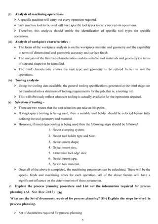
  • 5. (ii) Analysis of machining operations-  A specific machine will carry out every operation required.  Each machine tool to be used will have specific tool types to carry out certain operations.  Therefore, this analysis should enable the identification of specific tool types for specific operations. (iii) Analysis of workpiece characteristics –  The focus of the workpiece analysis is on the workpiece material and geometry and the capability in terms of dimensional and geometric accuracy and surface finish.  The analysis of the first two characteristics enables suitable tool materials and geometry (in terms of size and shape) to be identified.  The third characteristic allows the tool type and geometry to be refined further to suit the operations. (iv) Tooling analysis-  Using the tooling data available, the general tooling specifications generated at the third stage can be translated into a statement of tooling requirements for the job, that is, a tooling list.  This will obviously reflect whatever tooling is actually available for the operations required. (v) Selection of tooling –  There are two routes that the tool selection can take at this point.  If single-piece tooling is being used, then a suitable tool holder should be selected before fully defining the tool geometry and material.  However, if insert-type tooling is being used then the following steps should be followed: 1. Select clamping system; 2. Select tool holder type and Size; 3. Select insert shape; 4. Select insert size; 5. Determine tool edge dies; 6. Select insert type; 7. Select tool material.  Once all of the above is completed, the machining parameters can be calculated. These will be the speeds, feeds and machining times for each operation. All of the above factors will have a significant influence on the determination of these parameters. 2. Explain the process planning procedure and List out the information required for process planning. (AU Nov/Dec-2017) (Or) What are the Set of documents required for process planning? (Or) Explain the steps involved in process planning.  Set of documents required for process planning 5
  • 6.  Product design and the engineering drawings pertaining to all the components of the product. (i.e., components drawings, specifications and a bill of materials that defines how many of each component go into the product).  Machining/Machinability Data Handbook (Tables of cutting speeds, depth of cut, feeds for different processes and for different work materials).  Catalogues of various cutting tools and tool inserts.  Specifications of various machine tools available in the shop/catalogues of machine tools in the shop (speeds, feeds, capacity/power rating of motors, spindle size, table sizes etc.). (i) Sizes of standard materials commercially available in the market. (ii) Machine Hr. cost of all equipment available in the shop. (iii) Design Data Handbook. (iv) Charts of Limits, Fits & Tolerances. (v) Tables showing tolerances and surface finish obtainable for different machining processes. (vi) Tables of standard cost. (vii) Table of allowances (such as Personal Allowance, Fatigue Allowance etc. in % of standard time followed by the company). (viii) Process plans of certain standard components such as shafts, bushings, flanges etc. (ix) Handbooks (such as Tool Engineers Handbook, Design Data Handbook). Steps in process planning Required operations must be determined by examining the design data and employing basic machining data such as: 1. Holes can be made conveniently on drilling machines. 2. Flat surfaces can be machined easily on milling machines. 3. Cylindrical parts can be made using lathe. 4. Design data can be obtained from the part-drawing or from the finished part design file from the CAD system. The machines required for each operation must be determined. This selection depends on knowledge of machine factors, such as availability of the machine, specifications of machine tools available in the shop, accuracy grade of the m/c, table size, spindle size, Speed and feed ranges available, torque, power, machining rate and other size limitations. 5. The required tools for each identified machine or process must be determined. For selection of specialized tools knowledge and prior experience of process planner will be useful. 6. The optimum cutting parameters for each selected tool must be determined. These parameters include cutting speed, feed rate, depth of cut, and type of coolant/lubricant to be used. This determination depends on design data, such as work material, tool material, surface finish specifications and behaviour of cutting tool. Again expertise knowledge and prior experience of 6
  • 7. process planner and methods engineer will be useful in this regard. Machining data handbooks can also be referred. 7. Finally an optimum combination of these machining processes must be determined. The best process plan is the one which minimizes manufacturing time and cost. This provides a detailed plan for the economical manufacturing of the part. 8. The results of each of these five basic steps can be seen in the final form of the process plan 3. What are the factors that influence process planning? Discuss. Explain the steps in process selection with suitable example (AU N/D-2017) Practices of Process Planning The practices of process planning vary widely in modern industry, depending on such factors as :  Type of product  The equipment available, and  The volume of production (i.e., production quantity) The individual responsible for carrying out process planning / process analysis is the Process Engineer also known as process planner, process analyst or methods engineer. To be effective on his or her job, the process analyst must be familiar with material characteristics and manufacturing processes. Knowledge of the nature, types, and properties of standard materials and new materials will assist the process analyst in selecting the most appropriate process, equipment and methods for manufacturing a particular product. The process analyst must also be familiar with engineering drawings and product design. Drawings provide the part configuration and the dimensional tolerances and specifications that need to be met by the manufacturing process selected. In addition, the process planner must be familiar with the operating characteristics and costs of the production and tooling equipment, either available in the plant or to be purchased. Process Planning starts with a careful examination of the drawing or design of the part. The process planner must be able to analyze the engineering drawing and visualize the three dimensional part configuration. The part configuration must then be analyzed to determine its basic geometric components. Identifying these basic geometric elements assists the process planner in selecting the most appropriate process to manufacture the product. Process Selection 1. Consideration should be given to the following factors in selecting a particular process 2. Nature of part, including materials, tolerances, desired surface finish and operation required. 3. Method of fabrication including machining or assembling of similar parts or components. 4. Limitation of facilities including the plant and equipment available. 5. Possibility of likely product design changes to facilitate manufacturability or cost reduction. 7
  • 8. 6. In-plant and outside materials handling systems. 7. Inherent process to produce specified shape, surface, finish to give desired mechanical properties. 8. Available skill level of operators for the production. Sometimes the following additional factors affect the selection of a particular process. 9. Proposed or anticipated production requirements, including volume requirements, production rates and short- term or long- term production runs. 10. Total end-product costs. 11. Time available for tooling-up. 12. Materials receipt, storage, handling and transportation. Careful consideration of these factors will result in the selection of the most appropriate process for the manufacture of a particular product. Selection of an appropriate manufacturing process depends on many factors and requires considerable knowledge, skill and competence of the process planner or process analyst. Machine Selection Product manufacturing requires tools and machines that can produce economically as well as accurately. Economy depends to a large extent on the proper selection of the machine or process for the job that will give a satisfactory finished product. The selection of the machine is influenced, in turn by the quantity of items to be produced. Usually there is one machine best suited for a certain output. In small lot or jobbing type manufacture, general purpose machines such as the lathe, drill press, and milling machine may prove to be the best type since they areadoptable, have lower initial cost, require less maintenance, and possess the flexibility to meet changing conditions in the shop. However, a special purpose machine should be considered when large quantities of a standard product are to be produced. A machine built for one type of work or operation, such as the grinding of a piston or the machining of a cylinder head, will do the job well, quickly and at a low cost requiring only the service of a semi-skilled operator. Many of the special-purpose machines or tools differ from the usual standard type in that they have built into them some of the skill of the operator. A simple bolt may be produced on either a lathe or an automatic screw machine. The lathe operator must not only know how to make the bolt but must also be sufficiently skilled to operate the lathe. On the automatic machine the sequence of operations and movements of tools are controlled by cams and stops, and each item produced is identical with the previous one. This transfer of skill into the machine makes possible the use of less skillful operators, but it does requires greater skill in supervision and maintenance. Often it is not economical to make a machine completely automatic, as the cost may become prohibitive. The selection of the best machine or process for a given product requires knowledge of all possible production methods. Factors that must be considered are: 8
  • 9. • Volume of production (Quantity to be produced) i.e., no. of components to be produced. • Quality of finished product, and • Advantages and disadvantages of the various types of equipment capable of doing the work. Too much emphasis cannot be given to the fact that production can be by several methods, but usually there is one way that is most economical. Material selection Material selection is done by the product designer considering the requirements of the parts designed and the hardness, strength properties and other mechanical characteristics of the material. Cost and availability of the material are also considered. Material should be strong enough and at the same time manufacturing or producibility of the part using the given material and the process are also equally important. In the initial stages of design, the broad material groups such as ferrous or non-ferrous or other non- metallic materials can be considered. At a later stage specific material in the group can be identified. In certain products or components specific properties of materials such as fatigue strength, thermal conductivity, electrical properties like conductivity, magnetic permeability and insulation resistance may have to be considered. Mention the importance of calculating process parameters for various production process.(AU Apr/May 2024) Material Selection parameters  Functional requirements Reliability  Compatibility with other materials during service producibility or manufacturability Cost  Service life durability Aesthetics and appearance  Environmental Factors 4. Write notes on selection of cost for optimal processes. (Or) write notes on economics of process planning. (AU May/June-2016,2018) Discuss the economic considerations involved in process planning decisions.(AU Apr/May 2024) Two different types of processes can be used for the same job. The processes can be compared and optimum process selected with the help of break-even charts. Break-even charts: Break-even charts give the production engineer a powerful tool by which feasible alternative processes can be compared and the process which gives minimum cost can be selected. The fixed and variable costs for two alternative processes are plotted on a graph to a suitable scale as 9
  • 10. shown in Fig. For each process generally the variable cost is a linear function of the quantity manufactured. Therefore, once the fixed costs have been plotted, only one value for the variable costs is required at some value QA and the total cost lines can be drawn. F1 = Fixed costs for process (1) F2= Fixed costs for process (2) V1 = Variable costs for process (1) V2= Variable costs for process (2) QE = Break-even quantity at quantity QA TE = Total costs of manufacture at quantity QE Where these lines intersect is known as the break-even point, i.e., the point where the total cost of manufacture of quantity QE is same for both process (1) and process (2). The break-even chart tells us to : Use process (1) if the quantity to be manufactured ≤ QE Use process (2) if the quantity to be manufactured ≥ QE The value of QE can be scaled directly from the chart with sufficient accuracy, although it can also easily be calculated. 5. A component can be produced with equal ease on either a capstan lathe or on a single spindle cam operated automatic lathe. Find the break-even quantity QE if the following information is known. Capstan Lathe Automatic Lathe (a) Tooling cost Rs.30.00 Rs. 30.00 (b) Cost of cams ----- Rs.150.00 (c) Material cost/Component Rs.0.25 Rs. 0.25 (d) Operating labour cost Rs.2.50/hour Rs.1.00/hour (e) Cycle time/Component 5 minutes 1 minute (f) Setting up labour cost Rs.4.00/hour Rs. 4.00/hour (g) Setting up time 1 hour 8 hours 10
  • 11. (h) Machine overheads (setting and operating) 300% of (d) 1000% of (d) Capstan lathe: Overheads = 300 100 ×2.50=Rs.7.50/hour Fixed costs = tooling cost+setting−up−cost = 30.00 + 1 (4.00 + 7.50) = 30.00 + 11.50 = Rs. 41.50 = Rs.42 Variable costs/Component = (2.50×5|60)+0.25+(7.50×5|60) = 0.21 + 0.25 + 0.63 = Rs.1.09 Variable costs/1000 components = Rs.1090.00 Automatic lathe: Overheads = 1000 100 ×1.00=Rs.10.00/h Fixed costs = tooling cost+camcost+settingupcost 11
  • 12. = 30.00 + 150.00 + 8 (4.00 + 10.00) = 180.00 + 112.00 = Rs. 292.00 Variable costs/component = (1.00×1|60)+0.25+(10.00×1|60) = 0.02 + 0.25 + 0.17 = Rs. 0.44 Variable costs/1000 components = Rs. 440.00. These costs can now be plotted on a break-even chat (Fig.) to find the value of QE. QE is scaled from the break-even chart (Fig.) and found to be 385. If the batch size to be manufactured is equal to or less than 385 use the capstan lathe. If the batch size to be manufactured is equal to or greater than 385 use the automatic lathe. The above is the graphical method of determining Break-even Quantity. In this example no account was taken directly of the costs of depreciation and interest charges. The cost accountant’s methods of dealing with these charges will be determined by circumstances. If preferred, the break-even quantity QE can be calculated numerically thus : Total cost of producing a quantity x the capstan lathe = 41.50 + 1.09 x Total cost of producing a quantity x the automatic lathe = 292.00 + 0.44 x When x is equal to QE the total costs for each machine must equal 41.50 + 1.09 x = 292.00 + 0.44 x 1.09 x - 0.44 x = 292.00 – 41.50 0.65 x = 250.50 x = 250.50 0.65 =385at the break –even point. Thus Break-even chart or break-even analysis can be made to select the cost optimal process. 12
  • 13. 6. Th e following information is available for two machines in a manufacturing unit .break-even chart for the two Draw the machines and find out break-even quantity. Also find out which process is suitable for producing 4,000 items. Solution: This is a problem on comparison of cost of manufacturing the components on two different machines or processe 3.1 Volume of production (units) Variable cost = 1×1 60 + 1×25 60 + 1×4 60 =Rs.0.50 (i) Machine I : (Capstan lathe) Fixed costs = Tooling cost + set-up-cost + Overheads = 300 + 20 + 30 = Rs, 350 Variable cost = Operating labour cost + Maintenance charges + Power charges = 5×5 60 + 5×6 60 + 5×2 60 =Rs.1.08 (ii) Machine II: Fixed costs = Tooling cost + set-up-cost + Overheads = 1,800 + 150+ 250 = Rs.2, 200 13
  • 14. The break-even chart is shown in Fig... Break-even quantity QE = 3, 1 Now from the chart we see that machine I is economical if quantity to be produced is less than QE and machine II is economical if quantity to be produced is more than QE. To produce 4,000 units, machine II is economical. 7. Discuss about break-even point and break- even chart (1) Break-even point (BEP) represents the production quantity for which the total cost of producing the goods equals the total sales price. At break-even point there will be neither any profit nor any loss to the manufacturer. If Q = Quantity at BEP F = Fixed costs V = Variable cost per unit produced S = Selling price per unit Then F+(Q×V )=S×Q Q= F S−V (2) Break-even chart is a graphical representation of inter-relationship between quantity produced, cost of producing and sales return. The total cost of production (fixed cost +variable cost) and total sales return are plotted against quantity produced. The intersection of the total cost and total sales return lines gives the break-even point. Uses of Break-even Chart Break-even chart indicates the profit or loss at varying levels of production activity. From Figure we see that there will be loss to the organisation if the quantity produced is less than Q but if the quantity produced is more than Q, there will be profit 8. A factory has three sections in a machine shop. During one calendar year the following details are available: 14
  • 15. (i) Depreciation and rent of building Rs. 8,000 (ii) Supervisory charges Rs. 20,000 (iii) Indirect labour and indirect materials Rs. 7,000 (iv) Insurance charges Rs. 5,000 (v) Other charges (given below) Item of expenditure Section I Section II Section III Depreciation of machines Rs.5,000 Rs.7,000 Rs.4,000 Cost of power consumed Rs.3,000 Rs.5,000 Rs.2,000 Area occupied as percentage of total area 40 % 20% 40 % M/C hours worked 8,000 25,000 10,000 Maintenance charges Rs.5,000 Rs.5,000 Rs.5,000 Find out the machine-hour rate for each section if the common fixed expenses are to be apportioned on the basis of floor space occupied by each section. Solution: The total expenses For Section I are as follows : (i) Common fixed expenses such as depreciation and rent of building, supervisory charges, indirect labour and indirect materials and insurance charges are charged on the basis of floor area occupied. = (8,000 + 20,000 + 7,000 + 5,000) × 40 100 = Rs. 16,000 per year (ii) Depreciation of machines = Rs. 5,000 Power charges = Rs. 3,000 Maintenance charges = Rs. 2,000 Total expenses = 16,000 + 5,000 + 3,000 + 2,000 = Rs. 26,000 per year. Machine-hours worked during one year = 8,000 Machine – hour rate for section I = 26,000 8,000 =Rs.3.2 For Section II : Total cost = (8,000 +20,000+7,000+5,000) × 20 100 +(7,000+5,000+3,000) = Rs.23,000 per year 15
  • 16. Machine - hours worked during one year = 25,000 Machine - hour rate for section II = 23,000 25,000 =Rs.0.92 Similarly calculate the machine-hour rate for Section III = Rs. 2.30 9. What is Inspection? Write briefly about the different methods of inspections followed in industries. Inspection is the function by which the product quality is maintained The objectives of the Inspection are (ii)To sort out confirm and non-conforming product (iii) To initiate means to determine variations during manufacture (iii)To provide means to discover inefficiency during manufacture Stages of Inspection Inspection of incoming materials It consists of inspecting and checking all the purchased raw materials and parts that are supplied before they are taken on to stock or used in actual manufacturing. This inspection performed either at supplier’s place or at manufacturer dispatch or gate. Inspection of production process The inspection is done in parallel while the production is in processing. Inspection can be done at different work centers and at the critical production points. This has the advantages of minimize the wastage of time and money on defective units and preventing delays in assembly. Inspection of finished goods This is the last stage when finished goods are inspected and carried out before marketing to see that quality may be either rejected or sold at reduced price. Methods of inspection There are two methods of inspection. They are: i) 100% inspection, and ii) Sampling inspection, A. 100% inspection 100% or cent percent inspection is quite common when the number of parts to be inspection is relatively small. Here every part is examined as per the specification or standard established and 16
  • 17. acceptance or rejection of the part depends on the examination. B. Sampling inspection The use of sampling inspection is made when it is not practical or too costly to inspect each piece. A random sample from a batch is inspected and the batch is accepted if the sample is satisfactory. If the sample is not to the desired specification then either entire batch may be inspected piece by piece or rejected as a whole. Statistical methods are employed to determine the portion of total quality of batch which will serve as reliable sample. Types of inspection Inspection can be classified according to the type of data involved as:  Inspection of variable, and  Inspection of attributes Measurement instruments The selection of appropriate measurement instrument to be employed is basically depends on the type of quality characteristic of the component considered. Measurement: The different types of quality characteristics that are to be measured are: (i) Dimensions/size, (ii) Physical properties, (iii)Functionality, and (iv)Appearance. 10. Discuss about factors to be considered in the selection of jigs and fixtures for cost reduction (April/May-2018) Function of work holders The main purpose of any Work holding device is to position and hold a workpiece in a precise location while the manufacturing operation is being performed. In order to perform this function adequately, all work holders consist of four basic elements: Locating elements - That allow the work piece to be positioned correctly Structural elements- That can withstand the forces applied during the manufacturing operation. Clamping elements - That can withstand the forces applied during the manufacturing operation and maintain the position of the work piece. Fixing elements - That attach the work holder to the machine; There are many devices that adhere to the above definition that can be classified as general work holding devices as opposed to specialist work holding devices, that is, jigs and fixtures. General work holding devices can be classified as:  Vices  Clamps and abutments 17
  • 18.  Chucks Collets  Centers Mandrels  Face plates the entire above are sometimes referred to as low-cost jigs and fixtures. Use of jigs and fixtures For many machining and assembly operations, general-purpose work holding devices may not be sufficient. In these instances, these special work holding requirements are generally satisfied by designing and building special-purpose work holding devices known as jigs and fixtures. The design of special jigs, fixtures and tools is considered as one of three essential activities for facilitating interchangeable manufacture, along with process planning and the design of suitable limit gauges and gauging equipment. Consequently, the main reasons for the use of jigs and fixtures are:  Components can be produced quicker;  Greater interchangeability is obtained due to repeatability of manufacture which subsequently reduces assembly time;  Accuracy can be easily obtained and maintained;  Unskilled or semi-skilled labour may be used on a machine, resulting in reduced manufacturing costs. Jigs: A jig is a work holding device. However, jigs have a further important function and that is determining the location dimensions of specific features. In order to fully understand this function, the distinction between location and size dimensions must be defined. Strictly speaking, not all jigs provide guidance for tools. This is because in many assembly processes, such as welding, the jig merely holds the parts together in the correct orientation with respect to each other while the tool carries out the joining process. However, in the case of jigs being used with machining processes, they generally always provide guidance for the cutting tool. In summary, a jig is a specially designed and built work holding device, usually made of metal, and performs three basic functions Holding the component; Providing guidance for the cutting tools to determine the location dimension for the machining of a feature; Positively locating the component so that subsequent components are machined in the same manner. Jigs can usually be generally classified as either drilling jigs or boring jigs and are used for operations such as drilling, reaming, tapping, chamfering, counter boring, countersinking and boring operations. Fixture: A fixture is similar to a jig and can be defined as a special-purpose work holding device used during 18
  • 19. machining or assembly. However, fixtures are generally of heavier construction than jigs and also usually fixed to the machine table. The main function of a fixture is to positively locate the workpiece. However, unlike a jig, no guidance is provided for cutting tools. Fixtures are used in a variety of processes including milling, broaching, planing, grinding and turning. 11. Explain the importance of selection of the right quality assurance method during manufacturing (AU April/May-2018) All manufacturing organizations have the common goal of making a profit. The basic model of added value previously presented focuses on the main input of materials undergoing some transformation process and value being added to that material. A profit is made if the value added is greater than the cost to process the material. However, a profit will only be made if the customer is satisfied with the product. In the globally competitive market, this is where the factor of product quality is seen to be important. The transformation processes mentioned above in this instance are obviously manufacturing processes. However, all manufacturing processes have some degree of inherent variability, even highly automated processes such as CNC milling. Therefore, steps must be taken to ensure that the product specification is adhered to in spite of this variability. The starting point for this is the establishment of the capability of the processes being used. However, except in the case of the introduction of new processes, the capability of available processes should be known. These data should be documented and available to the process planner if required. Based on the capability of the process being employed, the process planner will determine which are the most appropriate quality assurance (QA) tools and techniques to employ. These will range from basic measurement tools such as callipers, micrometers and gauges to the use of coordinate measuring machines (CMMs). Also covered will be the application of statistical process control (SPC) methods. Although SPC and process capability studies will most probably be designed and carried out by quality engineering, it is essential that the process planner has an understanding of these in order to enter into meaningful dialogue with regards to process capability. In fact, the process planner will have to liaise closely with the quality function on a number of issues with regards to the process plan. These include: • Identifying inspection locations; • Identifying appropriate inspection and testing methods; the frequency of inspection and testing; • Evaluation of inspection and test data; Identifying corrective action where appropriate. All of the above will influence the processes, equipment, tools and manufacturing parameters to be used for a given job, particularly in the case where corrective action involves changing any of these. Therefore, the process planner requires a knowledge and understanding of all of these aspects of product quality. 12. Explain the factors to be considered in selection of process parameters The three Process parameters to be calculated for each operation during process planning are Cutting Speed Feed Rate Depth of Cut 19
  • 20. Cutting Speed: Cutting speed is known as surface cutting speed or surface speed, can be defined as Relative speed between the tool and the work piece Unit: meters per minute Factors affecting the selection of cutting speed  Nature of the cut  Continuous cut like turning, boring are done at higher cutting speed Shock initiated cuts in shaping, planning, slotting machine are done at lower cutting speed.  Intermittent cuts as in milling, hobbing are done at quite lower speed for dynamic loading  Work material  Harder and stronger materials are machined at lower cutting speed Soft, non-sticky materials can be machined at higher cutting speed  Cutting tool material Cutting  Fluid application Purpose of machining  Rough machining (lower cutting speed) Finish machining (higher cutting speed)  Kind of machining operation  Capacity of machine tool Condition  of machine tool Feed and feed rate Feed is the distance through which the tool advances into the work piece during one revolution of the workpiece or the cutter Feed rate is the speed at which the cutting tool penetrates the work piece Unit: millimeters per minute Factors affecting feed rate:  Nature of the cut Work material Cutting tool material  Cutting fluid application Purpose of machining  Kind of machining operation  Capacity of machine tool Depth of cut: Depth of cut is the thickness of the layer of metal removed in one cut or pass, measured in a direction perpendicular to the machined surface Unit: millimeter The feed and depth of cut for a particular operation depend on the material to be machined, surface finish required and tool used. 13. Prepare the operation and route sheet for the component shown in fig 20
  • 21. Solution Operation Sheet: Comp Procedure A.R.C Inc: Part Name Drill Plate Prepared by Drilling Part No :18 Date Operation No. Operation Description Machine Type Tool Dept Set up Time (m) Operation Time (min) Material /Part 01 Cutting Cutter Cutting Wheel Machin e Shop 30 20 Steel Plate 02 Surface Grinding Grinder Grinding Wheel Machin e Shop 15 30 Steel Plate 03 Drilling 4 Nos Drilling Machine Drill tool -12mm Machin e Shop 15 20 Steel Plate 04 Drilling Drilling Machine Drill tool -40 mm Machin e Shop 15 20 Steel Plate Rout Sheet 21 Routing sheet Part name Part no Drg no Quantity Material Planner Date Page 1 of 1 Order no Operation no Description Machine tool 01 Cut off 200x360 mm bar to 25 Hor. Bandsaw mm thick 02 Drill 40 mm dia. Drill press no 1 03 Drill 12 mm dia x 4 nos Drill press no 2 04 Surface Grind 5 micro meter Grinding machine no 1
  • 22. 22