


Registers and counters
- 1. REGISTERS AND COUNTERS By Dr. Heman Pathak Chapter -7
- 2. Registers A register is a group of flip-flops with each flip-flop capable of storing one bit of information. An n-bit register has a group of n flip-flops and is capable of storing any binary information of n bits. In addition to the flip-flops, a register may have combinational gates that perform certain data-processing tasks. In its broadest definition, a register consists of a group of flip-flops and gates that effect their transition. The flip-flops hold the binary information and the gates control when and how new information is transferred into the register.
- 3. Registers
- 4. Loading the Register The transfer of new information into a register is referred to as loading the register. Serial load: (transfer in serial mode) Transfer of new binary information into a register bit by bit Number of clock pulses needed to load the register = Number of flip-flops in the register Parallel load: (transfer in parallel mode) If all the bits of the register are loaded simultaneously with a common clock pulse transition, we say that the loading is done in parallel .
- 5. Registers with Parallel Load (RS Flip-flop) S R Q(T+1) 0 0 Q(T) 0 1 0 1 0 1 1 1 - L S R Q(T+1) 0 0 0 Q(T) 1 I I’ I 1 1 0 1 1 0 1 0 L I I’
- 7. Registers with Parallel Load (D Flip-flop) D Q(T+1) 0 0 1 1 L d Q(T+1) 0 Q(T) Q(T) 1 I I 1 1 1 1 0 0 L’ Q L I Q I L D
- 9. Shift Registers A register capable of shifting its binary information in one or both directions is called a shift register.
- 10. Shift Registers (Shift-Right) 1101 0 0 0 0 110 1 0 0 0 11 0 1 0 0 1 1 0 1 0 1 1 0 1 Serial load: (transfer in serial mode) Transfer of new binary information into a register bit by bit Number of clock pulses needed to load the register = Number of flip-flops in the register
- 11. Shift Registers (Shift-Left) 0 0 0 0 1101 0 0 0 1 101 0 0 1 1 01 0 1 1 0 1 1 1 0 1
- 12. Shift Registers A register capable of shifting its binary information in one or both directions is called a shift register. The logical configuration of a shift register consists of a chain of flip-flops in cascade, with the output of one flip-flop connected to the input of the next flip- flop. All flip-flops receive common clock pulses that initiate the shift from one stage to the next. The simplest possible shift register is one that uses only flip-flops (D). The output of a given flip-flop is connected to the D input of the flip-flop at its right. The clock is common to all flip-flops. The serial input determines what goes into the leftmost position during the shift. The serial output is taken from the output of the rightmost flip-flop.
- 13. Serial Transfer
- 17. Bidirectional Shift Register with Parallel Load A register capable of shifting in one direction only is called a unidirectional shift register. A register that can shift in both directions is called a bidirectional shift register. Some shift registers provide the necessary input and output terminals for parallel transfer. The most general shift register has all the capabilities listed below.
- 18. Bidirectional Shift Register with Parallel Load The most general shift register has all the capabilities listed below. 1. An input for clock pulses to synchronize all operations. 2. A shift-right operation and a serial input line associated with the shift right. 3. A shift-left operation and a serial input line associated with the shift-left. 4. A parallel load operation and n input lines associated with the parallel 5. transfer. 6. n parallel output lines. 7. A control state that leaves the information in the register unchanged 8. even though clock pulses are applied continuously.
- 19. Bidirectional Shift Register with Parallel Load A4 No Change A4 Shift Right SIR Shift Left A3 Parallel Load I4 A3 No Change A3 Shift Right A4 Shift Left A2 Parallel Load I3 A2 No Change A2 Shift Right A3 Shift Left A1 Parallel Load I2 A1 No Change A1 Shift Right A2 Shift Left SIL Parallel Load I1 A4 A3 A2 A1
- 21. Serial Addition
- 22. Serial Addition
- 23. Serial Addition
- 24. Asynchronous or Ripple Counter Counter is a sequential circuit which is used for counting input pulses passing through it. Counters are of two types. Asynchronous or ripple counters. Synchronous counters. A ripple counter is an asynchronous counter where only the first flip-flop is clocked by an external clock. All subsequent flip-flops are clocked by the output of the preceding flip-flop. Asynchronous counters are also called ripple-counters because of the way the clock pulse ripples it way through the flip-flops.
- 25. Binary Ripple Counter Negative-Edge-Triggered J-K Flip-Flop
- 30. Binary Down Ripple Counter Take the output from the complemented terminals of all flip-flops
- 31. Binary Down Ripple Counter Instead of Negative-Edge-Triggered flip-flops use Positive-Edge-Triggered flip-flops
- 32. Binary Down Ripple Counter
- 33. BCD or Decade Ripple Counter BCD or Decade Ripple Counter is a serial digital counter that counts ten digits. As it can go through 10 unique combinations of output, it is also called as “Decade counter”.
- 34. BCD or Decade Ripple Counter CLK Q8 Q4 Q2 Q1 Q1 CLK J K External 1 1 Q2 CLK J K Q1 Q8’ 1 Q4 CLK J K Q2 1 1 Q8 CLK J K Q1 Q2Q4 1
- 35. BCD or Decade Ripple Counter Q8 Q4 Q2 Q1 Q1 CLK J K External 1 1 Q2 CLK J K Q1 Q8’ 1 Q4 CLK J K Q2 1 1 Q8 CLK J K Q1 Q2Q4 1
- 36. BCD or Decade Ripple Counter
- 37. BCD or Decade Ripple Counter
- 38. Synchronous Counter Synchronous Counters are so called because the clock input of all the individual flip-flops within the counter are all clocked together at the same time by the same clock signal
- 40. Synchronous Up-Down Counter UP Down Action A4 A3 A2 A1 0 0 No Change 0 0 0 0 0 1 Down Counter A3’A2’A1’ A2’A1’ A1’ 1 1 0 Up Counter A3A2A1 A2A1 A1 1 1 1 Not Allowed - - - -
- 43. Synchronous BCD Counter TQ2 8421 00 01 11 10 00 0 1 1 0 01 0 1 1 0 11 X X X X 10 0 0 X X TQ4 8421 00 01 11 10 00 0 0 1 0 01 0 0 1 0 11 X X X X 10 0 0 X X TQ8 8421 00 01 11 10 00 0 0 0 0 01 0 0 1 0 11 X X X X 10 0 1 X X
- 44. Binary Counter with Parallel Load Counter is basically a register that goes through a predetermined sequence of state. This counter can be loaded in parallel with 4-Bit input data. Load Count Action 0 0 No Change 0 1 Count 1 0 Load 1 1 Load J K Action 0 0 No Change Q Q Count I I’ Load I I’ Load
- 46. Binary Counter with Parallel Load
- 48. Timing Sequences in Serial Mode
- 50. Timing Signals in Parallel Mode
- 51. Ring Counter A ring counter is a type of counter composed of flip- flops connected into a shift register, with the output of the last flip-flop fed to the input of the first, making a "circular" or "ring" structure.
- 52. Ring Counter Straight ring counter Q0 Q1 Q2 Q3 0 1 0 0 0 1 0 1 0 0 2 0 0 1 0 3 0 0 0 1 0 1 0 0 0 1 0 1 0 0 2 0 0 1 0 3 0 0 0 1 0 1 0 0 0
- 53. Ring Counter
- 54. Ring Counter
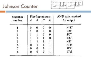
- 55. Johnson Counter In Johnson counter, the complemented output of last flip flop is connected to input of first flip flop.
- 56. Johnson Counter
- 57. Johnson Counter Total number of used states = 2*n =2*4 = 8 Total number of unused states = 2n – 2*n = 24-2*4 = 8 Advantages of Johnson counter: It can count twice the number of states the ring counter can count. Johnson ring counter is used to count the data in a continuous loop. Johnson counter is a self-decoding circuit. Disadvantages of Johnson counter: Johnson counter doesn’t count in a binary sequence. more number of states remain unutilized than the states being utilized. The number of flip flops needed is one half the number of timing signals.
- 58. Johnson Counter A B C D 0 0 1 0 1 0 0 1 0 1 0 0 1 0 1 0 1 1 0 1 0 1 1 0 1 0 1 1 0 1 0 1
- 59. Integrated Circuits An integrated circuit (IC) is a small silicon semiconductor crystal called a chip, containing the electronic components for the digital gates. The various gates are interconnected inside the chip to form the required circuit. The chip is mounted in a ceramic or plastic container, and connections are welded by thin gold wires to external pins to form the integrated circuit. The number of pins may range from 14 in a small IC package to 100 or more in a larger package.
- 60. Integrated Circuits As the technology of ICs has improved, the number of gates that can be put in a single chip has increased considerably. Small-scale integration (SSI) devices contain several independent gates in a single package. The inputs and outputs of the gates are connected directly to the pins in the package. The number of gates is usually less than 10 and is limited by the number of pins available in the IC. Medium-scale integration (MSI) devices have a complexity of approximately10 to 200 gates in a single package. They usually perform specific elementary digital functions such as decoders, adders, and registers.
- 61. Integrated Circuits LSI Large-scale integration (LSI) devices contain between 200 and a few thousand gates in a single package. They include digital systems, such as processors, memory chips, and programmable modules. Very-large-scale integration (VLSI) devices contain thousands of gates within a single package. Examples are large memory arrays and complex microcomputer chips. Because of their small size and low cost, VLSI devices have revolutionized the computer system design technology, giving designers the capability to create structures that previously were not economical.
- 62. Digital Logic Families Digital integrated circuits are classified not only by their logic operation but also by the specific circuit technology to which they belong. The circuit technology is referred to as a digital logic family. Each logic family has its own basic electronic circuit upon which more complex digital circuits and functions are developed. The basic circuit in each technology is either a NAND, a NOR, or an inverter gate. The electronic components that are employed in the construction of the basic circuit are usually used for the name of the technology. Many different logic families of integrated circuits have been introduced commercially.
- 63. Digital Logic Families TTL - Transistor-transistor logic ECL - Emitter-coupled logic MOS - Metal-oxide semiconductor CMOS - Complementary metal-oxide semiconductor I2L - Integrated Injection Logic
- 64. Transistor-Transistor Logic TTL is a widespread logic family that has been in operation for many years and is considered as standard. The transistor-transistor logic family was an evolution of a previous technology that used diodes and transistors for the basic NAND gate. This technology was called DTL, for "diode-transistor logic." Later the diodes were replaced by transistors to improve the circuit operation and the name of the logic family was changed to "transistor-transistor logic." This is the reason for mentioning the word "transistor" twice. Power supply voltage for TTL circuits is 5 volts, and the two logic levels are approximately 0 and 3.5 volts.
- 66. Emitter-Coupled Logic (ECL) The emitter-coupled logic (ECL) family provides the highest-speed digital circuits in integrated form. ECL is used in systems such as supercomputers and signal processors where high speed is essential. The transistors in ECL gates operate in a non-saturated state, a condition that allows the achievement of propagation delays of 1 to 2 nanoseconds.
- 68. Metal-Oxide Semiconductor (MOS) The metal-oxide semiconductor (MOS) is a unipolar transistor that depends on the flow of only one type of carrier, which may be electrons (n-channel) or holes (p-channel). This is in contrast to the bipolar transistor used in TTL and ECL gates, where both carriers exist during normal operation. A p-channel MOS is referred to as PMOS and an n-channel as NMOS. NMOS is the one that is commonly used in circuits with only one type of MOS transistor.
- 69. Complementary MOS (CMOS) The complementary MOS (CMOS) technology uses PMOS and NMOS transistors connected in a complementary fashion in all circuits. The most important advantages of CMOS over bipolar are the high packing density of circuits, a simpler processing technique during fabrication, and a more economical operation because of low power consumption.
- 71. INTEGRATED INJECTION LOGIC Integrated injection logic (IIL, I2L, or I2L) is a class of digital circuits built with multiple collector bipolar junction transistors (BJT). When introduced it had speed comparable to TTL yet was almost as low power as CMOS, making it ideal for use in VLSI (and larger) integrated circuits. The gates can be made smaller with this logic family than with CMOS because complementary transistors are not needed. Although the logic voltage levels are very close (High: 0.7V, Low: 0.2V), I2L has high noise immunity because it operates by current instead of voltage. I2L was developed in 1971 by Siegfried K. Wiedmann and Horst H. Berger who originally called it merged-transistor logic (MTL). A disadvantage of this logic family is that the gates draw power when not switching unlike with CMOS.