SlideShare a Scribd company logo
2
Most read
6
Most read
Types of Encoders and Decoders with Truth
Tables
The encoders and decoders play an essential role in
digital electronics projects; encoders & decoders are used to convert data from one form to another form. These are
frequently used in communication system such as telecommunication, networking, etc..to transfer data from one end
to the other end. Similarly, in the digital domain, for easy trans mission of data, it is often encrypted or placed within
codes,and then transmitted.At the receiver, the coded data is decrypted or gathered from the code and is processed
in order to be displayed or given to the load accordingly.
Types of Encoders and Decoders
An encoder is an electronic device used to convert an analogue signal to a digital signal such as a BCD code. It has a
number of input lines, but only one of the inputs is activated at a given time and produces an N -bit output code that
depends on the activated input. The encoders and decoders are used in many electronics projects to compress the
multiple number of inputs into smaller number of outputs. The encoder allows 2 power N inputs and generates N-
number of outputs. For example, in 4-2 encoder, if we give 4 inputs it produces only 2 outputs.
Encoder
Truth Table Of The Encoder
The decoders and encoders are designed with logic gate such as an OR-gate.There are different types of encoders
and decoders like 4 , 8, and 16 encoders and the truth table of encoder depends upon a particular encoder chosen by
the user.Here, a 4-bitencoder is being explained along with the truth table. The four-bit encoder allows onlyfour
inputs such as A0, A1, A2, A3 and generates the two outputs F0, F1, as shown in below diagram.
Simple Encoder
Encoder Truth Table
Priority Encoder
A normal encoder has a number of input lines amongst which only one of which is activated at a given time while a
priority encoder has more than one input,which is activated based on priority. Which means that,the priority encoders
are used to control interruptrequests byacting according to the highestpriorityrequest? Iftwo or more inputs are equal
to one – at the same time, the input having the highest priority will be preferred to take. Internal hardware will check
this condition and priority, which is set.
Priority Encoder
Multiplexer
The multiplexers and demultiplexers are digitalelectronic devices that are usedto control applications.A multiplexer is
a device that allows multiple input signals and produces a single output signal. For example, sometimes we need to
produce a single outputfrom multiple inputlines.Electronic multiplexer can be considered as a multiple inputand single
output lines.In this case,the multiplexer used selects the inputline to be sentto the output. The digital code is applied
to the selected inputs to generate respective output. The digital code is applied to the selected inputs to generate
respective outputA common application ofmultiplexing occurs when several embedded system devices share a single
transmission line or bus line while communicating with the device. Each device in succession has a brieftime to send
and receive the data. This is the special advantage of using this MUX.
Multiplexer
Introduction Of Decoder
The decoder is an electronic device that is used to convert digital signal to an analogue signal. It allows single input
line and produces multiple output lines. The decoders are used in many communication projects that are used to
communicate between two devices.The decoder allows N- inputs and generates 2 power N-numbers ofoutputs.For
example, if we give 2 inputs that will produce 4 outputs by using 4 by 2 decoder.
Decoder
Truth Table Of The Decoder
The encoders and decoders are designed with logic gates such as AND gate. There are different types of decoders
like 4, 8, and 16 decoders and the truth table of decoder depends upon a particular decoder chosen by the user. The
subsequentdescription is abouta 4-bitdecoder and its truth table. The four bit decoder allows only four outputs such
as A0, A1, A2, A3 and generates two outputs F0, F1, as shown in the below diagram.
Decoder Circuit
Decoder Truth T
2-to-4 line Decoder
In this type of encoders and decoders,decoders contain two inputs A0,A1, and four outputs represented byD0, D1,
D2, and D3. As you can see in the truth table – for each inputcombination,one outputline is activated.
2-to-4 Decoder
In this example,you can notice that, each output of the decoder is actually a minterm,resulting from a certain inputs
combination,thatis:
 D0 =A1 A0, ( minterm m0) which corresponds to input00
 D1 =A1 A0, ( minterm m1) which corresponds to input01
 D2 =A1 A0, ( minterm m2) which corresponds to input10
 D3 =A1 A0, ( minterm m3) which corresponds to input11
The circuit is implemented with AND gates,as shown in the figure. In this circuit, the logic equation for D0 is A1/A0,
and so on. Thus, each output of the decoder will be generated to the input combination.
3-8 DECODERS
This type of decoder contains two inputs: A0, A1, A2; and four outputs represented by D0, D1, D2, D3, D4, D5, D6,
and D7. As you can see in the truth table, for each input combination, one output line is activated. For example, an
input will activate the line A0, A1, A3 as 01 at the input has activated line D1, and so on.
3-to-8 Decoder
In this example, you can notice that, each output of the decoder is actually a minterm,resulting from a certain inputs
combination, that is;
 D0 =A2 A1 A0, ( minterm m0) which corresponds to input 000
 D1 = A2 A1 A0, ( minterm m1) which corresponds to input001
 D2 = A2 A1 A0, ( minterm m2) which corresponds to input010
 D3 = A2 A1 A0, ( minterm m3) which corresponds to input011
 D4 = A2 A1 A0, ( minterm m0) which corresponds to input100
 D5 = A2 A1 A0, ( minterm m1) which corresponds to input101
 D6 = A2 A1 A0, ( minterm m2) which corresponds to input110
 D7 = A2 A1 A0, ( minterm m3) which corresponds to input111
The circuitis implementedwith AND gates,as shown in the figure.In this circuit, the logic equation for D0 is A2/A1/A0/,
and so on. Thus, each output of the decoder will be generated to the input combination.
Decoder Design with NAND Gates
Some decoders are constructed with NAND rather than AND gates. In this case,all decoder outputs will be 1’s except
the one correspondingto the inputcode which will be 0.2-to-4 line decoder with an enable inputconstructed with NAND
gates.The circuit operates with complemented outputs and enables inputE’,which is also complemented to ma tch the
outputs of the decoder NAND gate. The decoder enabled when E’ is equal to zero. As represented by the truth table,
only one output can be equal to zero at any given time, all other outputs being equal to one. The outputs represent
minterm selected bythe inputs A1 and A0. The circuit is disabled when E’ is equal to one, regardless ofthe values of
the other two inputs. If the circuit is disabled, then none of the outputs are equal to zero.
Applications Of Decoder And Encoder; by Edgefx kits.com
Speed Synchronization of Multiple Motors in Industries
This system is used to synchronize motor speed by using RFtechnology. This projectis applicable to many industries
like steel plants,paper plants and textile mills,where the motors are used to design s imultaneously.All these motors
used on conveyer are designed to be synchronized.
Speed Synchronization of Multiple Motors in Industries by Edgefxkits.com
In this system, one motor output is given as the reference speed for the other motors to follow sam e speed. The
proposed system consists oftwo blocks:transmitter and receiver blocks,which are built with encoder and decoder. A
particular speed is sentbythe transmitter with the help ofthe decoder.The receiver receives the data and converts the
digital formatto send the receiver system,and maintains same speed as ithas received. Thus,if a particular speed is
set by the transmitter, then other motors run with the same speed by utilizing radio-frequency communication.
War- Field -Flying Robort with a Night Vision Flying Camera
This system with a wireless camera can wirelessly transmit a real-time video with night vision capabilities using RF
technology, which is for remote operation. This kind of robot can be helpful for spying in War fields.
War Field Flying Robort with NJight Vision Flying Cameraby Edgefxkits.com
In the transmitting end push buttons are used;commands are sentto the controller for controlling the movementof the
robot either in forward, backward, left, right, directions. The RF transmitter acts as a RF remote control that has the
advantage of adequate range (up to 200 meters) with proper antenna,while the receiver decodes before feeding it to
another microcontroller to drive DC motors via motor-driver IC for necessarywork. A wireless camera is mounted on
the robotbody for spying purposes,even in complete darkness byusing infrared lighting.The basic schematic diagram
is shown above.
Robotic Vehicle with Metal Detector
The projectis designed to devolpa robotic vehicle that can sense metals ahead ofit on its path similar to sensing land
mines.The robotis controlled bya remote using RFtechnology.At the transmitting end,using push buttons,commands
are sentto the receiver to control the movementofthe roboteither in forward,backward and left or right directions.At
the receiving end,two motors are interfaced to the microcontroller wheretheyare used for the movementofthe vehicle .
The RF transmitter acts as a RF remote control that has the advantage of adequate range (up to 200 meters) with
proper antenna, while the receiver decodes before feeding it to another microcontroller to drive DC motors via motor-
driver IC for necessary work.
Robotic Vehicle with Metal Detector by Edgefxkits.com
The RF transmitter acts as a RF remote control that has the advantage of adequate range (up to 200 meters) with
proper antenna, while the receiver decodes before feeding it to another microcontroller to drive DC motors via motor
driver IC for necessary work.
RF based Home Automation System
The main goal of this projectis to develop a home automation system with an RF- controlled remote.As technologyis
advancing so houses are also getting smarter.Modern houses are graduallyshifting from conventional switches to a
centralized control system, involving RF controlled switches.
RF based Home Automation System by Edgefxkits.com.
Presently, conventional wall switches located in differentparts of the house make itdifficultfor the user to approach
them for operations.Furthermore,itbecomes more & more difficultfor the elderly or physicallyhandicapped people
to do so.Remote controlled home automation system provides a simpler solution with RFtechnology.
Automatic Wireless Health Monitoring System in Hospitals for Patients
In this project,a wireless communication system is designed and developed for remote patientmonitoring.The primary
function of this system is to monitor the temperature ofa patient’s body, and displaythe same to the doctor through RF
communication.Itis a very tedious method.In this proposedsystem,a transmitting module continuouslyreads patient’s
body temperature through a digital temperature sensor; displays it on the LCD screen and sends it to the
microcontroller, which then transmits the encoded serial data over the air by RF (radio frequency) through an RF
module.
Automatic Wireless Health Monitoring System in Hospitals for Patients Block Diagram by Edgefxkits.com
Secret Code Enabled Secure Communication using RF Technology
The project is designed to send secure message by using a secretcode from a computer keyboard connected to the
transmitting unitvia RF technology. The message is retrieved at the receiver end only upon entering the secretcode
used bythe transmitter.Thus,complete secrecyis maintained in this communication process.This projecthas a unique
feature of tagging the messagewith a secret code as selectedbythe sender.The message is then transmitted through
the RF transmitting module. At the receiver end, the signal is received by the RF receiver module. The message is
then retrieved only if the secret code is known to the receiving personnel. In this project, the encoders and decoders
are used to transmitand receive the information. Once the secretcode is entered, then message is displayed on the
receiving unit on the LCD display.
Secret Code Enabled Secure Communication using RF Technology Block Diagram

More Related Content

PPTX
Satellite Power sub system
PDF
Impact of Partial Shading and bypass diode on PV panel Output Power
PDF
Mechatronics integrated aproach
PPTX
Z bus building algorithm
PPTX
Solar energy
PPTX
Dual axis solar tracking system using microcontroller
PPT
Presentation of single axis solar tracker
PPTX
Optimization in power system
Satellite Power sub system
Impact of Partial Shading and bypass diode on PV panel Output Power
Mechatronics integrated aproach
Z bus building algorithm
Solar energy
Dual axis solar tracking system using microcontroller
Presentation of single axis solar tracker
Optimization in power system

What's hot (20)

PPTX
Dc machines
PDF
Distributed generation & power quality unit 5
PPSX
Optimization for-power-sy-8631549
PPTX
Calculator design with lcd using fpga
DOCX
UNIT-III-DIGITAL SYSTEM DESIGN
PDF
Fault analysis
PPTX
Presentation solar
PPTX
BREAKDOWN IN GASES
PPTX
Distribution network reconfiguration for loss reduction and voltage
PPTX
Solar tracker
PPT
Phase locked loop
PPTX
Dual axis solar tracker
PDF
Programmable Switches for Programmable Logic Devices
PPT
Week 10 part 1 pe 6282 Block Diagrams
PPTX
faults in digital systems
PPTX
Lec 3 desgin via root locus
PPTX
Dynamic analysis of dc machine
PDF
Massive Integration of Offshore Using HVDC, 8th August 2012
PPTX
Focusing type solar collector
PDF
Balanced faults
Dc machines
Distributed generation & power quality unit 5
Optimization for-power-sy-8631549
Calculator design with lcd using fpga
UNIT-III-DIGITAL SYSTEM DESIGN
Fault analysis
Presentation solar
BREAKDOWN IN GASES
Distribution network reconfiguration for loss reduction and voltage
Solar tracker
Phase locked loop
Dual axis solar tracker
Programmable Switches for Programmable Logic Devices
Week 10 part 1 pe 6282 Block Diagrams
faults in digital systems
Lec 3 desgin via root locus
Dynamic analysis of dc machine
Massive Integration of Offshore Using HVDC, 8th August 2012
Focusing type solar collector
Balanced faults
Ad

Similar to Types of encoders and decoders with truth tables (20)

PPTX
ATT SMK.pptx
PPTX
decorder and encoder and its applications
PDF
Combinational Circuits - II (Encoders, Decoders, Multiplexers & PIDs).pdf
PDF
Analysis and Implementation of Hard-Decision Viterbi Decoding In Wireless Com...
PPTX
DTMF based load control
PPTX
Embedded Application : An Autonomous Robot or Line Follower Bot
PPTX
DLD Lecture No 22 Decoder Circuit and Types of Decoder.pptx
PDF
FYBSC IT Digital Electronics Unit IV Chapter I Multiplexer, Demultiplexer, AL...
DOCX
Mobile controll robot
PPTX
5.3 Data conversion
PPTX
B sc3 unit 4 combi..lckt
PPTX
presentation.pptx
PDF
Combinational circuits
PPTX
Analog to Digital .pptx
PPT
Chapter 4 combinational circuit
PPT
11.ppt
PPT
STLD-Combinational logic design
PDF
Lecture 8 Decoders & Encoders (combinational circuits)
DOCX
Training Report on embedded Systems and Robotics
ATT SMK.pptx
decorder and encoder and its applications
Combinational Circuits - II (Encoders, Decoders, Multiplexers & PIDs).pdf
Analysis and Implementation of Hard-Decision Viterbi Decoding In Wireless Com...
DTMF based load control
Embedded Application : An Autonomous Robot or Line Follower Bot
DLD Lecture No 22 Decoder Circuit and Types of Decoder.pptx
FYBSC IT Digital Electronics Unit IV Chapter I Multiplexer, Demultiplexer, AL...
Mobile controll robot
5.3 Data conversion
B sc3 unit 4 combi..lckt
presentation.pptx
Combinational circuits
Analog to Digital .pptx
Chapter 4 combinational circuit
11.ppt
STLD-Combinational logic design
Lecture 8 Decoders & Encoders (combinational circuits)
Training Report on embedded Systems and Robotics
Ad

Recently uploaded (20)

PDF
Digital Logic Computer Design lecture notes
PDF
PRIZ Academy - 9 Windows Thinking Where to Invest Today to Win Tomorrow.pdf
PPTX
MET 305 2019 SCHEME MODULE 2 COMPLETE.pptx
PDF
Embodied AI: Ushering in the Next Era of Intelligent Systems
PPTX
UNIT-1 - COAL BASED THERMAL POWER PLANTS
PPTX
Infosys Presentation by1.Riyan Bagwan 2.Samadhan Naiknavare 3.Gaurav Shinde 4...
PPT
Project quality management in manufacturing
DOCX
ASol_English-Language-Literature-Set-1-27-02-2023-converted.docx
PPTX
additive manufacturing of ss316l using mig welding
PPTX
Strings in CPP - Strings in C++ are sequences of characters used to store and...
PDF
July 2025 - Top 10 Read Articles in International Journal of Software Enginee...
PDF
keyrequirementskkkkkkkkkkkkkkkkkkkkkkkkkkkkkkkkkkkkk
PPTX
Lesson 3_Tessellation.pptx finite Mathematics
PPTX
Welding lecture in detail for understanding
PPTX
Geodesy 1.pptx...............................................
PDF
Mitigating Risks through Effective Management for Enhancing Organizational Pe...
PDF
Evaluating the Democratization of the Turkish Armed Forces from a Normative P...
PPTX
Lecture Notes Electrical Wiring System Components
DOCX
573137875-Attendance-Management-System-original
PPTX
Engineering Ethics, Safety and Environment [Autosaved] (1).pptx
Digital Logic Computer Design lecture notes
PRIZ Academy - 9 Windows Thinking Where to Invest Today to Win Tomorrow.pdf
MET 305 2019 SCHEME MODULE 2 COMPLETE.pptx
Embodied AI: Ushering in the Next Era of Intelligent Systems
UNIT-1 - COAL BASED THERMAL POWER PLANTS
Infosys Presentation by1.Riyan Bagwan 2.Samadhan Naiknavare 3.Gaurav Shinde 4...
Project quality management in manufacturing
ASol_English-Language-Literature-Set-1-27-02-2023-converted.docx
additive manufacturing of ss316l using mig welding
Strings in CPP - Strings in C++ are sequences of characters used to store and...
July 2025 - Top 10 Read Articles in International Journal of Software Enginee...
keyrequirementskkkkkkkkkkkkkkkkkkkkkkkkkkkkkkkkkkkkk
Lesson 3_Tessellation.pptx finite Mathematics
Welding lecture in detail for understanding
Geodesy 1.pptx...............................................
Mitigating Risks through Effective Management for Enhancing Organizational Pe...
Evaluating the Democratization of the Turkish Armed Forces from a Normative P...
Lecture Notes Electrical Wiring System Components
573137875-Attendance-Management-System-original
Engineering Ethics, Safety and Environment [Autosaved] (1).pptx

Types of encoders and decoders with truth tables

  • 1. Types of Encoders and Decoders with Truth Tables The encoders and decoders play an essential role in digital electronics projects; encoders & decoders are used to convert data from one form to another form. These are frequently used in communication system such as telecommunication, networking, etc..to transfer data from one end to the other end. Similarly, in the digital domain, for easy trans mission of data, it is often encrypted or placed within codes,and then transmitted.At the receiver, the coded data is decrypted or gathered from the code and is processed in order to be displayed or given to the load accordingly. Types of Encoders and Decoders An encoder is an electronic device used to convert an analogue signal to a digital signal such as a BCD code. It has a number of input lines, but only one of the inputs is activated at a given time and produces an N -bit output code that depends on the activated input. The encoders and decoders are used in many electronics projects to compress the multiple number of inputs into smaller number of outputs. The encoder allows 2 power N inputs and generates N- number of outputs. For example, in 4-2 encoder, if we give 4 inputs it produces only 2 outputs.
  • 2. Encoder Truth Table Of The Encoder The decoders and encoders are designed with logic gate such as an OR-gate.There are different types of encoders and decoders like 4 , 8, and 16 encoders and the truth table of encoder depends upon a particular encoder chosen by the user.Here, a 4-bitencoder is being explained along with the truth table. The four-bit encoder allows onlyfour inputs such as A0, A1, A2, A3 and generates the two outputs F0, F1, as shown in below diagram. Simple Encoder
  • 3. Encoder Truth Table Priority Encoder A normal encoder has a number of input lines amongst which only one of which is activated at a given time while a priority encoder has more than one input,which is activated based on priority. Which means that,the priority encoders are used to control interruptrequests byacting according to the highestpriorityrequest? Iftwo or more inputs are equal to one – at the same time, the input having the highest priority will be preferred to take. Internal hardware will check this condition and priority, which is set.
  • 4. Priority Encoder Multiplexer The multiplexers and demultiplexers are digitalelectronic devices that are usedto control applications.A multiplexer is a device that allows multiple input signals and produces a single output signal. For example, sometimes we need to produce a single outputfrom multiple inputlines.Electronic multiplexer can be considered as a multiple inputand single output lines.In this case,the multiplexer used selects the inputline to be sentto the output. The digital code is applied to the selected inputs to generate respective output. The digital code is applied to the selected inputs to generate respective outputA common application ofmultiplexing occurs when several embedded system devices share a single transmission line or bus line while communicating with the device. Each device in succession has a brieftime to send and receive the data. This is the special advantage of using this MUX. Multiplexer Introduction Of Decoder The decoder is an electronic device that is used to convert digital signal to an analogue signal. It allows single input line and produces multiple output lines. The decoders are used in many communication projects that are used to communicate between two devices.The decoder allows N- inputs and generates 2 power N-numbers ofoutputs.For example, if we give 2 inputs that will produce 4 outputs by using 4 by 2 decoder.
  • 5. Decoder Truth Table Of The Decoder The encoders and decoders are designed with logic gates such as AND gate. There are different types of decoders like 4, 8, and 16 decoders and the truth table of decoder depends upon a particular decoder chosen by the user. The subsequentdescription is abouta 4-bitdecoder and its truth table. The four bit decoder allows only four outputs such as A0, A1, A2, A3 and generates two outputs F0, F1, as shown in the below diagram. Decoder Circuit
  • 6. Decoder Truth T 2-to-4 line Decoder In this type of encoders and decoders,decoders contain two inputs A0,A1, and four outputs represented byD0, D1, D2, and D3. As you can see in the truth table – for each inputcombination,one outputline is activated. 2-to-4 Decoder In this example,you can notice that, each output of the decoder is actually a minterm,resulting from a certain inputs combination,thatis:  D0 =A1 A0, ( minterm m0) which corresponds to input00  D1 =A1 A0, ( minterm m1) which corresponds to input01
  • 7.  D2 =A1 A0, ( minterm m2) which corresponds to input10  D3 =A1 A0, ( minterm m3) which corresponds to input11 The circuit is implemented with AND gates,as shown in the figure. In this circuit, the logic equation for D0 is A1/A0, and so on. Thus, each output of the decoder will be generated to the input combination. 3-8 DECODERS This type of decoder contains two inputs: A0, A1, A2; and four outputs represented by D0, D1, D2, D3, D4, D5, D6, and D7. As you can see in the truth table, for each input combination, one output line is activated. For example, an input will activate the line A0, A1, A3 as 01 at the input has activated line D1, and so on. 3-to-8 Decoder In this example, you can notice that, each output of the decoder is actually a minterm,resulting from a certain inputs combination, that is;  D0 =A2 A1 A0, ( minterm m0) which corresponds to input 000  D1 = A2 A1 A0, ( minterm m1) which corresponds to input001  D2 = A2 A1 A0, ( minterm m2) which corresponds to input010  D3 = A2 A1 A0, ( minterm m3) which corresponds to input011  D4 = A2 A1 A0, ( minterm m0) which corresponds to input100  D5 = A2 A1 A0, ( minterm m1) which corresponds to input101  D6 = A2 A1 A0, ( minterm m2) which corresponds to input110  D7 = A2 A1 A0, ( minterm m3) which corresponds to input111 The circuitis implementedwith AND gates,as shown in the figure.In this circuit, the logic equation for D0 is A2/A1/A0/, and so on. Thus, each output of the decoder will be generated to the input combination. Decoder Design with NAND Gates Some decoders are constructed with NAND rather than AND gates. In this case,all decoder outputs will be 1’s except the one correspondingto the inputcode which will be 0.2-to-4 line decoder with an enable inputconstructed with NAND gates.The circuit operates with complemented outputs and enables inputE’,which is also complemented to ma tch the outputs of the decoder NAND gate. The decoder enabled when E’ is equal to zero. As represented by the truth table, only one output can be equal to zero at any given time, all other outputs being equal to one. The outputs represent
  • 8. minterm selected bythe inputs A1 and A0. The circuit is disabled when E’ is equal to one, regardless ofthe values of the other two inputs. If the circuit is disabled, then none of the outputs are equal to zero. Applications Of Decoder And Encoder; by Edgefx kits.com Speed Synchronization of Multiple Motors in Industries This system is used to synchronize motor speed by using RFtechnology. This projectis applicable to many industries like steel plants,paper plants and textile mills,where the motors are used to design s imultaneously.All these motors used on conveyer are designed to be synchronized. Speed Synchronization of Multiple Motors in Industries by Edgefxkits.com In this system, one motor output is given as the reference speed for the other motors to follow sam e speed. The proposed system consists oftwo blocks:transmitter and receiver blocks,which are built with encoder and decoder. A particular speed is sentbythe transmitter with the help ofthe decoder.The receiver receives the data and converts the digital formatto send the receiver system,and maintains same speed as ithas received. Thus,if a particular speed is set by the transmitter, then other motors run with the same speed by utilizing radio-frequency communication. War- Field -Flying Robort with a Night Vision Flying Camera This system with a wireless camera can wirelessly transmit a real-time video with night vision capabilities using RF technology, which is for remote operation. This kind of robot can be helpful for spying in War fields.
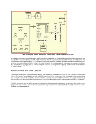
  • 9. War Field Flying Robort with NJight Vision Flying Cameraby Edgefxkits.com In the transmitting end push buttons are used;commands are sentto the controller for controlling the movementof the robot either in forward, backward, left, right, directions. The RF transmitter acts as a RF remote control that has the advantage of adequate range (up to 200 meters) with proper antenna,while the receiver decodes before feeding it to another microcontroller to drive DC motors via motor-driver IC for necessarywork. A wireless camera is mounted on the robotbody for spying purposes,even in complete darkness byusing infrared lighting.The basic schematic diagram is shown above. Robotic Vehicle with Metal Detector The projectis designed to devolpa robotic vehicle that can sense metals ahead ofit on its path similar to sensing land mines.The robotis controlled bya remote using RFtechnology.At the transmitting end,using push buttons,commands are sentto the receiver to control the movementofthe roboteither in forward,backward and left or right directions.At the receiving end,two motors are interfaced to the microcontroller wheretheyare used for the movementofthe vehicle . The RF transmitter acts as a RF remote control that has the advantage of adequate range (up to 200 meters) with proper antenna, while the receiver decodes before feeding it to another microcontroller to drive DC motors via motor- driver IC for necessary work.
  • 10. Robotic Vehicle with Metal Detector by Edgefxkits.com The RF transmitter acts as a RF remote control that has the advantage of adequate range (up to 200 meters) with proper antenna, while the receiver decodes before feeding it to another microcontroller to drive DC motors via motor driver IC for necessary work. RF based Home Automation System The main goal of this projectis to develop a home automation system with an RF- controlled remote.As technologyis advancing so houses are also getting smarter.Modern houses are graduallyshifting from conventional switches to a centralized control system, involving RF controlled switches. RF based Home Automation System by Edgefxkits.com. Presently, conventional wall switches located in differentparts of the house make itdifficultfor the user to approach them for operations.Furthermore,itbecomes more & more difficultfor the elderly or physicallyhandicapped people to do so.Remote controlled home automation system provides a simpler solution with RFtechnology. Automatic Wireless Health Monitoring System in Hospitals for Patients
  • 11. In this project,a wireless communication system is designed and developed for remote patientmonitoring.The primary function of this system is to monitor the temperature ofa patient’s body, and displaythe same to the doctor through RF communication.Itis a very tedious method.In this proposedsystem,a transmitting module continuouslyreads patient’s body temperature through a digital temperature sensor; displays it on the LCD screen and sends it to the microcontroller, which then transmits the encoded serial data over the air by RF (radio frequency) through an RF module. Automatic Wireless Health Monitoring System in Hospitals for Patients Block Diagram by Edgefxkits.com Secret Code Enabled Secure Communication using RF Technology The project is designed to send secure message by using a secretcode from a computer keyboard connected to the transmitting unitvia RF technology. The message is retrieved at the receiver end only upon entering the secretcode used bythe transmitter.Thus,complete secrecyis maintained in this communication process.This projecthas a unique feature of tagging the messagewith a secret code as selectedbythe sender.The message is then transmitted through the RF transmitting module. At the receiver end, the signal is received by the RF receiver module. The message is then retrieved only if the secret code is known to the receiving personnel. In this project, the encoders and decoders are used to transmitand receive the information. Once the secretcode is entered, then message is displayed on the receiving unit on the LCD display.
  • 12. Secret Code Enabled Secure Communication using RF Technology Block Diagram