SlideShare a Scribd company logo
Types of scanners
contentscontents
 IntroductionIntroduction
 Types of scannersTypes of scanners
 Their characteristicsTheir characteristics
 ConclusionConclusion
 ReferencesReferences
INTRODUCTIONINTRODUCTION
 A scanning system employs a detectorA scanning system employs a detector
with a narrow field of view that is sweptwith a narrow field of view that is swept
across the terrain to produce an image.across the terrain to produce an image.
 When photons of electromagneticWhen photons of electromagnetic
energy radiated / reflected from theenergy radiated / reflected from the
terrain encounter the detector, anterrain encounter the detector, an
electrical signal is produced that varieselectrical signal is produced that varies
in proportion to the number of photons.in proportion to the number of photons.
The electrical signal is amplified,The electrical signal is amplified,
recorded on magnetic tape and playedrecorded on magnetic tape and played
back later to produce an image.back later to produce an image.
Scanning systemScanning system
Types of scannersTypes of scanners
 1 – Cross-track scanner1 – Cross-track scanner
 2 – Along-track scanner2 – Along-track scanner
 3 – Circular scanner3 – Circular scanner
 4 – Side- scanning system4 – Side- scanning system
 A scanning system used to collect dataA scanning system used to collect data
over a variety of different wavelengthover a variety of different wavelength
ranges is called aranges is called a multispectral scannermultispectral scanner
(MSS),(MSS), and is the most commonly usedand is the most commonly used
scanning system.scanning system.
 There are two main modes or methodsThere are two main modes or methods
of scanning employed to acquireof scanning employed to acquire
multispectral image data –multispectral image data –
 Cross-track scanningCross-track scanning
 Along-track scanningAlong-track scanning
Cross-Track Scanners
(whiskbroom)
It employs a faceted mirror that is
rotated by an electric motor , with a
horizontal axis of rotation aligned
parallel with the flight direction.
The mirror sweeps across the terrain
in a pattern of parallel scan lines
oriented normal to the flight direction.
Energy radiated or reflected from the
ground is focused onto the detector by
the secondary mirror.
WhiskbroomWhiskbroom
A whiskbroom scannerA whiskbroom scanner
utilizes a mirror that sweeps inutilizes a mirror that sweeps in
a direction perpendicular toa direction perpendicular to
the flight path.the flight path.
As the mirror sweeps acrossAs the mirror sweeps across
the path, EMR is directed viathe path, EMR is directed via
the optics into a series ofthe optics into a series of
mirrors and prisms.mirrors and prisms.
The EMR is split into itsThe EMR is split into its
various wavelengths andvarious wavelengths and
focused onto detectors.focused onto detectors.
Detectors measure EMR fromDetectors measure EMR from
point on ground, storing thepoint on ground, storing the
value as digital number.value as digital number.
Image is built of multiple rowsImage is built of multiple rows
of discrete ground segmentsof discrete ground segments
called “pixels”called “pixels”
DD –– diameter of circulardiameter of circular
ground area viewedground area viewed
(spactial resolution)(spactial resolution)
ß -- instantaneous fieldinstantaneous field
of viewof view
H –H – flying height aboveflying height above
terrain.terrain.
D=H’ßD=H’ß
Cross-track scanner mirror systemCross-track scanner mirror system
WhiskbroomWhiskbroom
Types of scanners
Landsat with whiskbroom scannerLandsat with whiskbroom scanner
Characteristics of LandsatCharacteristics of Landsat
Landsats 4 and 5 carry both MSS and TM
sensors
Satellites orbit at an altitude of 705 km,
with a 16-day cycle.
Satellites designed and operate to collect
data over a 185 km swath.
MSS and TM sensors detect reflected
radiation from Earth’s surface in visible and
near IR wavelengths.
  
Current Landsat TM Ground ReceivingCurrent Landsat TM Ground Receiving
StationsStations
Types of scanners
Along-track scannersAlong-track scanners
(pushbroom)(pushbroom)
Along-track scanners also
use the forward motion of
the platform to record
successive scan lines and
build up a two-dimensional
image, perpendicular to the
flight direction. However,
instead of a scanning mirror,
they use a linear array of
detectors (A) located at the
focal plane of the image (B)
formed by lens systems (C),
which are "pushed" along in
the flight track direction
A push broom scanner usesA push broom scanner uses
a one-dimensional array ofa one-dimensional array of
charged couple devicescharged couple devices
aligned in a directionaligned in a direction
perpendicular to the flightperpendicular to the flight
direction.direction.
Each CCD is aimed at aEach CCD is aimed at a
specific point on the groundspecific point on the ground
with the neighbouring CCDwith the neighbouring CCD
viewing the neighbouringviewing the neighbouring
piece of ground.piece of ground.
The entire line of imageThe entire line of image
data (line of pixels) isdata (line of pixels) is
acquired at one time.acquired at one time.
Analogous to the bristles ofAnalogous to the bristles of
a brooma broom
Types of scanners
Types of scanners
Charge-Coupled Devices (CCD)Charge-Coupled Devices (CCD)
 The CCD senses incoming light through theThe CCD senses incoming light through the
photoelectric effect , which is the actionphotoelectric effect , which is the action
of certain materials that release anof certain materials that release an
electron when hit with a photon of light.electron when hit with a photon of light.
The electrons emitted within the CCD areThe electrons emitted within the CCD are
fenced within nonconductive boundaries,fenced within nonconductive boundaries,
so that they remain within the area of theso that they remain within the area of the
photon strike.photon strike.
 As long as light is allowed to impinge on aAs long as light is allowed to impinge on a
photosite, electrons will accumulate inphotosite, electrons will accumulate in
that pixel.that pixel.
 When the source of light isWhen the source of light is
extinguished simple electronicextinguished simple electronic
circuitry and a microprocessor orcircuitry and a microprocessor or
computer are used to unload the CCDcomputer are used to unload the CCD
array, count the electrons in eacharray, count the electrons in each
pixel, and process the resulting datapixel, and process the resulting data
into an image on a video monitor orinto an image on a video monitor or
other output media.other output media.
SPOT carries two identical HRV(HighSPOT carries two identical HRV(High
Resolution Visible) pushbroom scannersResolution Visible) pushbroom scanners
SPOT Satellite CharacteristicsSPOT Satellite Characteristics
Began in France in 1978 – a long-term
commercial system
Carries two identical HRV pushbroom
scanners (High Resolution Visible)
operating in one of two modes:
Panchromatic – a single visible band
(0.51 – 0.73mm) with a spatial resolution
of 10 m x 10 m
Multispectral – three images produced:
one for each band – 0.50-0.59mm
(green), 0.61-0.68mm (red) and 0.79-
0.89 mm (near IR) with a spatial
resolution of 20 m x 20 m
Field of View (FOV), Instantaneous Field of View (IFOV)
Dwell time is the time required for the detector IFOV to sweep
across a ground cell. The longer
dwell time allows more energy to impinge on the detector, which
creates a stronger signal.
Wiskbroom Pushbroom
Advantages of Along-track scannersAdvantages of Along-track scanners
 Measure the energy from each groundMeasure the energy from each ground
resolution cell for a longer period ofresolution cell for a longer period of
timetime
 More energy to be detected andMore energy to be detected and
improves the radiometric resolutionimproves the radiometric resolution
 Smaller IFOVs and narrowerSmaller IFOVs and narrower
bandwidths for each detectorbandwidths for each detector
Scanning System ComparedScanning System Compared
Cross- track Along- trackCross- track Along- track
scannerscanner scannerscanner
1-Angular field of view - Wider1-Angular field of view - Wider - Narrower- Narrower
2-Mechanical system2-Mechanical system - Complex- Complex - Simple- Simple
3-Optical system3-Optical system - Simple- Simple - Complex- Complex
4-Spectral range of - Wider4-Spectral range of - Wider - Narrower- Narrower
detectorsdetectors
5-Dwell time5-Dwell time - Shorter - Longer- Shorter - Longer
Circular ScannersCircular Scanners
 In this , the scan motor and mirror areIn this , the scan motor and mirror are
mounted with a vertical axis of rotationmounted with a vertical axis of rotation
that sweeps circular path on the terrain.that sweeps circular path on the terrain.
 Only the forward portion of the sweep isOnly the forward portion of the sweep is
recorded to produce images.recorded to produce images.
 Circular scanners are used forCircular scanners are used for
reconnaissance purposes in aircraft.reconnaissance purposes in aircraft.
 The images are displayed in real time onThe images are displayed in real time on
a screen in the cockpit to guide thea screen in the cockpit to guide the
pilot.pilot.
Circular ScannerCircular Scanner
Side-Scanning SystemSide-Scanning System
 Side-scanning system isSide-scanning system is
primarily an active systemprimarily an active system
which provides their ownwhich provides their own
energy sources.energy sources.
 The example given hereThe example given here
is a radar system thatis a radar system that
transmits pulses oftransmits pulses of
microwave energy to onemicrowave energy to one
side of the flight path andside of the flight path and
records the energyrecords the energy
scattered from the terrainscattered from the terrain
back to the antennaback to the antenna..
System Technology Spectral range Bands Bandwidth
1-Daedalus
scanner
Scanning
(cross-Track)
0.38 to 1.10 4 0.10
2-GER Scanner Scanning
(Cross-Track)
0.50 to 2.50 63 0.025 to 0.175
3-AVIRIS
Scanner
Scanning
(Cross – track)
0.40 to 2.50 224 0.010
4-SFSI Scanner Scanning
(Along-track)
1.22 to 2.42 115 0.010
ConclusionConclusion
Many electronic remote sensors acquireMany electronic remote sensors acquire
data using scanning systems, whichdata using scanning systems, which
employ a sensor with a narrow field ofemploy a sensor with a narrow field of
view (i.e. IFOV) that sweeps over theview (i.e. IFOV) that sweeps over the
terrain to build up and produce a two-terrain to build up and produce a two-
dimensional image of the surface.dimensional image of the surface.
Scanning systems can be used on bothScanning systems can be used on both
aircraft and satellite platforms and haveaircraft and satellite platforms and have
essentially the same operating principles.essentially the same operating principles.
A scanning system useA scanning system usedd to collect datato collect data
over a variety of different wavelengthover a variety of different wavelength
ranges is called a multispectral scannerranges is called a multispectral scanner
(MSS)(MSS)..
ReferencesReferences
1 FLOYD F. SABINS1 FLOYD F. SABINS(1996/1997) REMOTE(1996/1997) REMOTE
SENSING principles and Interpretation W.H.SENSING principles and Interpretation W.H.
FREEMAN AND COMPANY NEWYORK 3FREEMAN AND COMPANY NEWYORK 3rdrd
Edition, page 15 - 28.Edition, page 15 - 28.
22 Remote sensing in meteorologyRemote sensing in meteorology byby Murat ilhanMurat ilhan
33 Remote SensingRemote Sensing
Electro-optical Sensors byElectro-optical Sensors by Vicki DrakeVicki Drake
44 INTRODUCTION TO REMOTE SENSINGINTRODUCTION TO REMOTE SENSING
Paul R. BaumannPaul R. Baumann
Professor of Geography (Emeritus)Professor of Geography (Emeritus)
State University of New YorkState University of New York
College at OneontaCollege at Oneonta
Oneonta, New York 13820Oneonta, New York 13820
Types of scanners

More Related Content

PDF
Optical remote sensing
PPTX
Remote sensing - Scanners
PPTX
SENSORS AND SCANNERS.pptx
PPTX
Multispectral remote sensing
PPTX
Multi Spectral Scanning Systems
PPT
Remote sensing-presentaion
PPTX
Landsat.pptx
PPTX
Landsat
Optical remote sensing
Remote sensing - Scanners
SENSORS AND SCANNERS.pptx
Multispectral remote sensing
Multi Spectral Scanning Systems
Remote sensing-presentaion
Landsat.pptx
Landsat

What's hot (20)

PPTX
GIS Map Projection
PPTX
Remote Sensing Platforms and Sensors
PDF
Sensors for remote sensing
PPT
Spectral signatures
PPTX
Remote sensing - Sensors, Platforms and Satellite orbits
PPTX
Remote sensing
PPTX
Types of aerial photographs
PPTX
Microwave remote sensing
PDF
Aerial photography abraham thomas
PPTX
Aerial photography- Concept and Terminologies
PPT
Photogrammetry-part 1
PDF
Aerial photographs and their interpretation
PDF
Introduction to Landsat
PPTX
Aerial photography.pptx
PPTX
Stereoscopic parallax
PPTX
Thermal remote sensing
PPTX
Basics of Remote Sensing
PDF
Principle of aerial photography and types.ppt
PPTX
Digital image processing
PPT
Radar remote sensing, P K MANI
GIS Map Projection
Remote Sensing Platforms and Sensors
Sensors for remote sensing
Spectral signatures
Remote sensing - Sensors, Platforms and Satellite orbits
Remote sensing
Types of aerial photographs
Microwave remote sensing
Aerial photography abraham thomas
Aerial photography- Concept and Terminologies
Photogrammetry-part 1
Aerial photographs and their interpretation
Introduction to Landsat
Aerial photography.pptx
Stereoscopic parallax
Thermal remote sensing
Basics of Remote Sensing
Principle of aerial photography and types.ppt
Digital image processing
Radar remote sensing, P K MANI
Ad

Similar to Types of scanners (20)

PPTX
Remote Sensing Data Acquisition,Scanning/Imaging systems
PPTX
Scanners and sensors used in remote sensing.pptx
PPTX
RS-GISUNIT -2.pptxRS-GISUNIT -2.pptxXXXX
PPT
Earth Viewing Infrared Space System Sensor
PDF
Needs and Emerging Trends of Remote Sensing
PPTX
Continuing chapter rs.pptx
PPTX
data input technique Digitization and GPS.pptx
PPTX
Resolution and scanning system
PPTX
remote sensing Sensors and platform.pptx
PPTX
Scanners, image resolution, orbit in remote sensing, pk mani
PDF
Ar_Utkarsh Khandelwal_ARGIS_Chapter 4.pdf
DOCX
Remote sensing by Priyanshu kumar, 9608684800
PPT
Ppt on remote sensing system
PPT
Remote Sensin
PPTX
Lec 5, Techniques for data collection.pptx
PPTX
Modern Surveying Instrument.pptx
PPTX
Gis unit 3
PPTX
BASIC CONCEPT OF REMOTE SENSING
Remote Sensing Data Acquisition,Scanning/Imaging systems
Scanners and sensors used in remote sensing.pptx
RS-GISUNIT -2.pptxRS-GISUNIT -2.pptxXXXX
Earth Viewing Infrared Space System Sensor
Needs and Emerging Trends of Remote Sensing
Continuing chapter rs.pptx
data input technique Digitization and GPS.pptx
Resolution and scanning system
remote sensing Sensors and platform.pptx
Scanners, image resolution, orbit in remote sensing, pk mani
Ar_Utkarsh Khandelwal_ARGIS_Chapter 4.pdf
Remote sensing by Priyanshu kumar, 9608684800
Ppt on remote sensing system
Remote Sensin
Lec 5, Techniques for data collection.pptx
Modern Surveying Instrument.pptx
Gis unit 3
BASIC CONCEPT OF REMOTE SENSING
Ad

More from PRAMODA G (20)

PPTX
Session_3_The-Interior-of-the-Earth.pptx
PPTX
Session_2_ Earth -System-Components.pptx
PPTX
Session_1_Introduction - to-Geology.pptx
PPTX
Volcanoes-Explosive-Wonders-of-the-Earth.pptx
PPTX
Dimensional - Stone - Technology .pptx
PPTX
Natural-Disasters, Earthquake andTsunami,
PPTX
The-Epic-Journey-of-Oceans-Continents-and-Mountains.pptx
PPTX
Earthquakes, Geology, Disaster management
PPTX
The Cephalopods (Mollusca)- Palaeontology
PPT
Continental-Drift-The-Shifting-Continents.ppt
PPTX
Siwalik- Stratigraphy
PPTX
Hydrogeology
PPTX
Waves and their significance
PPTX
coastal erosion
PPT
Karst topography
PPT
Glacial processes and their land forms.
PPT
Dams
PDF
Upsc geologist syllabus exam pattern
DOCX
Role of non government organizations in disaster management
DOCX
Disaster Management System in India - Notes
Session_3_The-Interior-of-the-Earth.pptx
Session_2_ Earth -System-Components.pptx
Session_1_Introduction - to-Geology.pptx
Volcanoes-Explosive-Wonders-of-the-Earth.pptx
Dimensional - Stone - Technology .pptx
Natural-Disasters, Earthquake andTsunami,
The-Epic-Journey-of-Oceans-Continents-and-Mountains.pptx
Earthquakes, Geology, Disaster management
The Cephalopods (Mollusca)- Palaeontology
Continental-Drift-The-Shifting-Continents.ppt
Siwalik- Stratigraphy
Hydrogeology
Waves and their significance
coastal erosion
Karst topography
Glacial processes and their land forms.
Dams
Upsc geologist syllabus exam pattern
Role of non government organizations in disaster management
Disaster Management System in India - Notes

Recently uploaded (20)

PPTX
The Healthy Child – Unit II | Child Health Nursing I | B.Sc Nursing 5th Semester
PDF
TR - Agricultural Crops Production NC III.pdf
PDF
3rd Neelam Sanjeevareddy Memorial Lecture.pdf
PDF
Saundersa Comprehensive Review for the NCLEX-RN Examination.pdf
PPTX
Microbial diseases, their pathogenesis and prophylaxis
PDF
grade 11-chemistry_fetena_net_5883.pdf teacher guide for all student
PDF
BÀI TẬP BỔ TRỢ 4 KỸ NĂNG TIẾNG ANH 9 GLOBAL SUCCESS - CẢ NĂM - BÁM SÁT FORM Đ...
PDF
Complications of Minimal Access Surgery at WLH
PPTX
master seminar digital applications in india
PDF
Module 4: Burden of Disease Tutorial Slides S2 2025
PPTX
Pharma ospi slides which help in ospi learning
PDF
RMMM.pdf make it easy to upload and study
PDF
2.FourierTransform-ShortQuestionswithAnswers.pdf
PDF
Physiotherapy_for_Respiratory_and_Cardiac_Problems WEBBER.pdf
PPTX
Cell Structure & Organelles in detailed.
PPTX
school management -TNTEU- B.Ed., Semester II Unit 1.pptx
PPTX
Cell Types and Its function , kingdom of life
PDF
01-Introduction-to-Information-Management.pdf
PDF
Supply Chain Operations Speaking Notes -ICLT Program
PDF
VCE English Exam - Section C Student Revision Booklet
The Healthy Child – Unit II | Child Health Nursing I | B.Sc Nursing 5th Semester
TR - Agricultural Crops Production NC III.pdf
3rd Neelam Sanjeevareddy Memorial Lecture.pdf
Saundersa Comprehensive Review for the NCLEX-RN Examination.pdf
Microbial diseases, their pathogenesis and prophylaxis
grade 11-chemistry_fetena_net_5883.pdf teacher guide for all student
BÀI TẬP BỔ TRỢ 4 KỸ NĂNG TIẾNG ANH 9 GLOBAL SUCCESS - CẢ NĂM - BÁM SÁT FORM Đ...
Complications of Minimal Access Surgery at WLH
master seminar digital applications in india
Module 4: Burden of Disease Tutorial Slides S2 2025
Pharma ospi slides which help in ospi learning
RMMM.pdf make it easy to upload and study
2.FourierTransform-ShortQuestionswithAnswers.pdf
Physiotherapy_for_Respiratory_and_Cardiac_Problems WEBBER.pdf
Cell Structure & Organelles in detailed.
school management -TNTEU- B.Ed., Semester II Unit 1.pptx
Cell Types and Its function , kingdom of life
01-Introduction-to-Information-Management.pdf
Supply Chain Operations Speaking Notes -ICLT Program
VCE English Exam - Section C Student Revision Booklet

Types of scanners

  • 2. contentscontents  IntroductionIntroduction  Types of scannersTypes of scanners  Their characteristicsTheir characteristics  ConclusionConclusion  ReferencesReferences
  • 3. INTRODUCTIONINTRODUCTION  A scanning system employs a detectorA scanning system employs a detector with a narrow field of view that is sweptwith a narrow field of view that is swept across the terrain to produce an image.across the terrain to produce an image.  When photons of electromagneticWhen photons of electromagnetic energy radiated / reflected from theenergy radiated / reflected from the terrain encounter the detector, anterrain encounter the detector, an electrical signal is produced that varieselectrical signal is produced that varies in proportion to the number of photons.in proportion to the number of photons. The electrical signal is amplified,The electrical signal is amplified, recorded on magnetic tape and playedrecorded on magnetic tape and played back later to produce an image.back later to produce an image.
  • 5. Types of scannersTypes of scanners  1 – Cross-track scanner1 – Cross-track scanner  2 – Along-track scanner2 – Along-track scanner  3 – Circular scanner3 – Circular scanner  4 – Side- scanning system4 – Side- scanning system
  • 6.  A scanning system used to collect dataA scanning system used to collect data over a variety of different wavelengthover a variety of different wavelength ranges is called aranges is called a multispectral scannermultispectral scanner (MSS),(MSS), and is the most commonly usedand is the most commonly used scanning system.scanning system.  There are two main modes or methodsThere are two main modes or methods of scanning employed to acquireof scanning employed to acquire multispectral image data –multispectral image data –  Cross-track scanningCross-track scanning  Along-track scanningAlong-track scanning
  • 7. Cross-Track Scanners (whiskbroom) It employs a faceted mirror that is rotated by an electric motor , with a horizontal axis of rotation aligned parallel with the flight direction. The mirror sweeps across the terrain in a pattern of parallel scan lines oriented normal to the flight direction. Energy radiated or reflected from the ground is focused onto the detector by the secondary mirror.
  • 8. WhiskbroomWhiskbroom A whiskbroom scannerA whiskbroom scanner utilizes a mirror that sweeps inutilizes a mirror that sweeps in a direction perpendicular toa direction perpendicular to the flight path.the flight path. As the mirror sweeps acrossAs the mirror sweeps across the path, EMR is directed viathe path, EMR is directed via the optics into a series ofthe optics into a series of mirrors and prisms.mirrors and prisms. The EMR is split into itsThe EMR is split into its various wavelengths andvarious wavelengths and focused onto detectors.focused onto detectors. Detectors measure EMR fromDetectors measure EMR from point on ground, storing thepoint on ground, storing the value as digital number.value as digital number. Image is built of multiple rowsImage is built of multiple rows of discrete ground segmentsof discrete ground segments called “pixels”called “pixels”
  • 9. DD –– diameter of circulardiameter of circular ground area viewedground area viewed (spactial resolution)(spactial resolution) ß -- instantaneous fieldinstantaneous field of viewof view H –H – flying height aboveflying height above terrain.terrain. D=H’ßD=H’ß
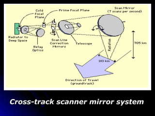
  • 10. Cross-track scanner mirror systemCross-track scanner mirror system
  • 13. Landsat with whiskbroom scannerLandsat with whiskbroom scanner
  • 14. Characteristics of LandsatCharacteristics of Landsat Landsats 4 and 5 carry both MSS and TM sensors Satellites orbit at an altitude of 705 km, with a 16-day cycle. Satellites designed and operate to collect data over a 185 km swath. MSS and TM sensors detect reflected radiation from Earth’s surface in visible and near IR wavelengths.
  • 15.    Current Landsat TM Ground ReceivingCurrent Landsat TM Ground Receiving StationsStations
  • 17. Along-track scannersAlong-track scanners (pushbroom)(pushbroom) Along-track scanners also use the forward motion of the platform to record successive scan lines and build up a two-dimensional image, perpendicular to the flight direction. However, instead of a scanning mirror, they use a linear array of detectors (A) located at the focal plane of the image (B) formed by lens systems (C), which are "pushed" along in the flight track direction
  • 18. A push broom scanner usesA push broom scanner uses a one-dimensional array ofa one-dimensional array of charged couple devicescharged couple devices aligned in a directionaligned in a direction perpendicular to the flightperpendicular to the flight direction.direction. Each CCD is aimed at aEach CCD is aimed at a specific point on the groundspecific point on the ground with the neighbouring CCDwith the neighbouring CCD viewing the neighbouringviewing the neighbouring piece of ground.piece of ground. The entire line of imageThe entire line of image data (line of pixels) isdata (line of pixels) is acquired at one time.acquired at one time. Analogous to the bristles ofAnalogous to the bristles of a brooma broom
  • 21. Charge-Coupled Devices (CCD)Charge-Coupled Devices (CCD)  The CCD senses incoming light through theThe CCD senses incoming light through the photoelectric effect , which is the actionphotoelectric effect , which is the action of certain materials that release anof certain materials that release an electron when hit with a photon of light.electron when hit with a photon of light. The electrons emitted within the CCD areThe electrons emitted within the CCD are fenced within nonconductive boundaries,fenced within nonconductive boundaries, so that they remain within the area of theso that they remain within the area of the photon strike.photon strike.  As long as light is allowed to impinge on aAs long as light is allowed to impinge on a photosite, electrons will accumulate inphotosite, electrons will accumulate in that pixel.that pixel.
  • 22.  When the source of light isWhen the source of light is extinguished simple electronicextinguished simple electronic circuitry and a microprocessor orcircuitry and a microprocessor or computer are used to unload the CCDcomputer are used to unload the CCD array, count the electrons in eacharray, count the electrons in each pixel, and process the resulting datapixel, and process the resulting data into an image on a video monitor orinto an image on a video monitor or other output media.other output media.
  • 23. SPOT carries two identical HRV(HighSPOT carries two identical HRV(High Resolution Visible) pushbroom scannersResolution Visible) pushbroom scanners
  • 24. SPOT Satellite CharacteristicsSPOT Satellite Characteristics Began in France in 1978 – a long-term commercial system Carries two identical HRV pushbroom scanners (High Resolution Visible) operating in one of two modes: Panchromatic – a single visible band (0.51 – 0.73mm) with a spatial resolution of 10 m x 10 m Multispectral – three images produced: one for each band – 0.50-0.59mm (green), 0.61-0.68mm (red) and 0.79- 0.89 mm (near IR) with a spatial resolution of 20 m x 20 m
  • 25. Field of View (FOV), Instantaneous Field of View (IFOV) Dwell time is the time required for the detector IFOV to sweep across a ground cell. The longer dwell time allows more energy to impinge on the detector, which creates a stronger signal. Wiskbroom Pushbroom
  • 26. Advantages of Along-track scannersAdvantages of Along-track scanners  Measure the energy from each groundMeasure the energy from each ground resolution cell for a longer period ofresolution cell for a longer period of timetime  More energy to be detected andMore energy to be detected and improves the radiometric resolutionimproves the radiometric resolution  Smaller IFOVs and narrowerSmaller IFOVs and narrower bandwidths for each detectorbandwidths for each detector
  • 27. Scanning System ComparedScanning System Compared Cross- track Along- trackCross- track Along- track scannerscanner scannerscanner 1-Angular field of view - Wider1-Angular field of view - Wider - Narrower- Narrower 2-Mechanical system2-Mechanical system - Complex- Complex - Simple- Simple 3-Optical system3-Optical system - Simple- Simple - Complex- Complex 4-Spectral range of - Wider4-Spectral range of - Wider - Narrower- Narrower detectorsdetectors 5-Dwell time5-Dwell time - Shorter - Longer- Shorter - Longer
  • 28. Circular ScannersCircular Scanners  In this , the scan motor and mirror areIn this , the scan motor and mirror are mounted with a vertical axis of rotationmounted with a vertical axis of rotation that sweeps circular path on the terrain.that sweeps circular path on the terrain.  Only the forward portion of the sweep isOnly the forward portion of the sweep is recorded to produce images.recorded to produce images.  Circular scanners are used forCircular scanners are used for reconnaissance purposes in aircraft.reconnaissance purposes in aircraft.  The images are displayed in real time onThe images are displayed in real time on a screen in the cockpit to guide thea screen in the cockpit to guide the pilot.pilot.
  • 30. Side-Scanning SystemSide-Scanning System  Side-scanning system isSide-scanning system is primarily an active systemprimarily an active system which provides their ownwhich provides their own energy sources.energy sources.  The example given hereThe example given here is a radar system thatis a radar system that transmits pulses oftransmits pulses of microwave energy to onemicrowave energy to one side of the flight path andside of the flight path and records the energyrecords the energy scattered from the terrainscattered from the terrain back to the antennaback to the antenna..
  • 31. System Technology Spectral range Bands Bandwidth 1-Daedalus scanner Scanning (cross-Track) 0.38 to 1.10 4 0.10 2-GER Scanner Scanning (Cross-Track) 0.50 to 2.50 63 0.025 to 0.175 3-AVIRIS Scanner Scanning (Cross – track) 0.40 to 2.50 224 0.010 4-SFSI Scanner Scanning (Along-track) 1.22 to 2.42 115 0.010
  • 32. ConclusionConclusion Many electronic remote sensors acquireMany electronic remote sensors acquire data using scanning systems, whichdata using scanning systems, which employ a sensor with a narrow field ofemploy a sensor with a narrow field of view (i.e. IFOV) that sweeps over theview (i.e. IFOV) that sweeps over the terrain to build up and produce a two-terrain to build up and produce a two- dimensional image of the surface.dimensional image of the surface. Scanning systems can be used on bothScanning systems can be used on both aircraft and satellite platforms and haveaircraft and satellite platforms and have essentially the same operating principles.essentially the same operating principles. A scanning system useA scanning system usedd to collect datato collect data over a variety of different wavelengthover a variety of different wavelength ranges is called a multispectral scannerranges is called a multispectral scanner (MSS)(MSS)..
  • 33. ReferencesReferences 1 FLOYD F. SABINS1 FLOYD F. SABINS(1996/1997) REMOTE(1996/1997) REMOTE SENSING principles and Interpretation W.H.SENSING principles and Interpretation W.H. FREEMAN AND COMPANY NEWYORK 3FREEMAN AND COMPANY NEWYORK 3rdrd Edition, page 15 - 28.Edition, page 15 - 28. 22 Remote sensing in meteorologyRemote sensing in meteorology byby Murat ilhanMurat ilhan 33 Remote SensingRemote Sensing Electro-optical Sensors byElectro-optical Sensors by Vicki DrakeVicki Drake 44 INTRODUCTION TO REMOTE SENSINGINTRODUCTION TO REMOTE SENSING Paul R. BaumannPaul R. Baumann Professor of Geography (Emeritus)Professor of Geography (Emeritus) State University of New YorkState University of New York College at OneontaCollege at Oneonta Oneonta, New York 13820Oneonta, New York 13820