


uc 1 (design electronical control system).ppt
- 1. Industrial Automation and Control Technology Management Unit of Competence: Design Electronic Control Systems Module Title: Designing Electronic Control Systems Module Code: EEL IAC5 01 0511 Level:- V 1
- 2. An electronic controller is a device that receives an input signal from a measured process variable, compares this value with that of a predetermined control point value (set point), and determines the appropriate amount of output signal required by the final control element to provide corrective action within a control loop.
- 3. What is process control Control in process industries refers to the regulation of all aspects of the process. Precise control of level, temperature, pressure and flow is important in many process applications. Process control is the ability to monitor and adjust a process to give a desired output. 3
- 4. What is process control It is used in industry to maintain quality and improve performance. An example of a simple process that is controlled is keeping the temperature of a room at a certain temperature using a heater and a thermostat. 4
- 5. History of process control The various methods for process control are as follows Manual control Hard-wired control Electronics control PLC control
- 6. Manual control (Human – Aided control) In this case a human has been added to the process. The human can adjust the height by opening and closing the valve to change Q out in such a way that the height can be adjusted . In this case the controlled variable is still the height, but the height can be manipulated by a person changing the manipulated or controlling variable Q out
- 7. Manual control (Human – Aided control) sight tube height
- 8. In this process a human can regulate the level using a sight tube ‘S’ to compare the level ‘h’ to the objective ‘H’ and adjust the value to change the level. By a succession of incremental opening and closing of the valve, the human can bring the level to set point value ‘H’ And maintain it there by continues monitoring of the sight tube and adjustment of the valve, the height is regulated. Manual control (Human – Aided control)
- 9. Automatic control Automation is basically the delegation of human control functions to technical equipment aimed towards achieving For automatic control the system is modified as shown below. An automatic level-control system replaces the human with a controller and uses a sensor to measure the level
- 10. In the previous slide the person is replaced by an automatic control system. The height is measured by a sensor (a float or electronic), and a controller (typically a microcomputer or other electronic circuit) will signal an actuator to open/close the valve controlling Qout Again the height is adjusted to a set point H by manipulating or controlling variable Qout
- 11. Advantages of automatic controller: Higher productivity Superior quality of end product Efficient usage of energy and raw materials Improved safety in working conditions Time saving
- 12. Although this method served the purpose for many years, it had certain limitations as listed below Bulky and complex wiring Involves lot of rework to implement changes in control logic. The work can be started only when the task is fully defined and this leads to longer project time High power consumption
- 13. Electronics control With the advantage of electronics, the logic gates started replacing the relays and auxiliary contactors in the control circuits. The bimetallic and motorized timers were replaced by electronic timers, counters. With incorporation of these changes, we got the benefits of Reduced space requirements. Energy saving Less maintenance and hence greater reliability Easy fault finding However even with electronic, the implementation of changes in the control logic as well as reducing the project lead time was not possible.
- 14. Programmable Logic Controller A digitally operating electronic apparatus which uses a programming memory for the internal storage of instructions for implementing specific functions such as logic, sequencing, timing, counting and arithmetic to control through digital or analog modules, various types of machines or process. Instead of achieving the desired control or automation through physical wiring of control devices, in PLC it is achieved through a program or says software.
- 15. PROCESS CONTROL Process control refers to the methods that are used to control process variables when manufacturing product. For example, factors such as the proportion of one ingredient to another, the temperature of the materials, how well the ingredients are mixed, and the pressure under which the materials are held can significantly impact the quality of an end product. Manufacturers control the production process for three reasons: Reduce variability Increase efficiency Ensure safety
- 16. Reduce Variability Process control can reduce variability in the end product, which ensures a consistently high-quality product. Manufacturers can also save money by reducing variability. For example, in a gasoline blending process, as many as 12 or more different components may be blended to make a specific grade of gasoline. If the refinery does not have precise control over the flow of the separate components, the gasoline may get too much of the high-octane components. As a result, customers would receive a higher grade and more expensive gasoline than they paid for, and the refinery would lose money. The opposite situation would be customers receiving a lower grade at a higher price.
- 18. Increase Efficiency Some processes need to be maintained at a specific point to maximize efficiency. For example, a control point might be the temperature at which a chemical reaction takes place. Accurate control of temperature ensures process efficiency. Manufacturers save money by minimizing the resources required to produce the end product
- 19. Ensure Safety A run-away process, such as an out-of-control nuclear or chemical reaction, may result if manufacturers do not maintain precise control of all of the process variables. The consequences of a run-away process can be catastrophic Precise process control may also be required to ensure safety. For example, maintaining proper boiler pressure by controlling the inflow in preventing boiler implosions that can clearly threaten the safety of workers.
- 20. The Control Loop Three Tasks Control loops in the process control industry work in the same way, requiring three tasks to occur. Measurement Comparison Adjustment
- 21. In Figure below, a level transmitter (LT) measures the level in the tank and transmits a signal associated with the level reading to a controller (LIC). The controller compares the reading to a predetermined value, in this case, the maximum tank level established by the plant operator, and finds that the values are equal. The controller then sends a signal to the device that can bring the tank level back to a lower level—a valve at the bottom of the tank. The valve opens to let some liquid out of the tank.
- 22. Many different instruments and devices may or may not be used in control loops (e.g., transmitters, sensors, controllers, valves, pumps), but the three tasks of measurement, comparison, and adjustment are always present.
- 23. Process Control Terms Process Variable A process variable is a condition of the process fluid (a liquid or gas) that can change the manufacturing process in some way. In the example of you sitting by the fire, the process variable was temperature. In the example of the tank in Figure above, the process variable is level.
- 24. SETPOINT The set point is a value for a process variable that is desired to be maintained. For example, if a process temperature needs to kept within 5 °C of 100 °C, then the set point is 100 °C. A temperature sensor can be used to help maintain the temperature at set point. The sensor is inserted into the process, and a controller compares the temperature reading from the sensor to the set point.
- 25. If the temperature reading is 110 °C, then the controller determines that the process is above set point and signals the fuel valve of the burner to close slightly until the process cools to 100 °C. Set points can also be maximum or minimum values. For example, level in tank cannot exceed 20 feet Common process variables include:
- 26. Common process variables include Pressure Flow Level Temperature Density Ph (acidity or alkalinity) Liquid interface (the relative amounts of different liquids that are combined in a vessel) Mass Conductivity
- 27. Process Control Control Terminology Controlled variable (or “output variable”) • Manipulated variable (or “input variable”) • Disturbance variable (or “load variable”)
- 28. Controlled variables (Measured variables) - The measured variable is the condition of the process fluid that must be kept at the designed set-point., which are also called output variables. Manipulated variables - these input variables are adjusted dynamically to keep the controlled variables at their set-points. Disturbance variables - these are also called "load" variables and represent input variables that can cause the controlled variables to deviate from their respective set points.
- 29. Control Terminology(2) Set-point change - implementing a change in the operating conditions. The set-point signal is changed and the manipulated variable is adjusted appropriately to achieve the new operating conditions. Also called servomechanism (or "servo") control. Disturbance change - the process transient behavior when a disturbance enters, also called regulatory control or load change. A control system should be able to return each controlled variable back to its set-point.
- 30. Control the tank temperature at constant value The controlled variable is temperature The manipulated variable is heat The disturbance variable is tank inlet cold water
- 32. Feedforward vs. Feedback Control
- 34. Feedback Control: Distinguishing feature: measure the controlled variable • It is important to make a distinction between negative feedback and positive feedback. Engineering Usage vs. Social Sciences • Advantages: Corrective action is taken regardless of the source of the disturbance. Reduces sensitivity of the controlled variable to disturbances and changes in the process
- 35. Disadvantages: No corrective action occurs until after the disturbance has upset the process, that is, until after x differs from xsp. Very oscillatory responses, or even instability…
- 36. Feed forward Control: Distinguishing feature: measure a disturbance variable • Advantage: Correct for disturbance before it upsets the process. Takes corrective action before the process is upset (cf. FB control.) Theoretically capable of "perfect control“ Does not affect system stability
- 37. Disadvantage: Must be able to measure the disturbance. No corrective action for unmeasured disturbances. Disturbance must be measured (capital, operating costs) Requires more knowledge of the process to be controlled (process model) Ideal controllers that result in "perfect control”: may be physically unrealizable. Use practical controllers such as lead-lag units
- 38. 3) Feed forward Plus Feedback Control ◦ FF Control • Attempts to eliminate the effects of measurable disturbances. ◦ FB Control • Corrects for unmeasurable disturbances, modeling errors, etc.
- 40. BATCH CONTROL Batch processes are those processes that are taken from start to finish in batches. For example, mixing the ingredients for a juice drinks is often a batch process. Typically, a limited amount of one flavor (e.g., orange drink or apple drink) is mixed at a time. Batch processes often involve getting the correct proportion of ingredients into the batch.
- 41. Level, flow, pressure, temperature, and often mass measurements are used at various stages of batch processes. A disadvantage of batch control is that the process must be frequently restarted. Start-up presents control problems because, typically, all measurements in the system are below set point at start-up. Another disadvantage is that as recipes change, control instruments may need to be recalibrated.
- 43. Error Error is the difference between the measured variable and the Set point and can be either positive or negative. In the temperature control loop example, the error is the difference between the 110 °C measured variable and the 100 °C set point—that is, the error is +10 °C.
- 44. The objective of any control scheme is to minimize or eliminate error. Therefore, it is imperative that error be well understood. Any error can be seen as having three major components. These three components are shown in the figure on the following page
- 45. Magnitude The magnitude of the error is simply the deviation between the values of the set point and the process variable. The magnitude of error at any point in time compared to the previous error provides the basis for determining the change in error. The change in error is also an important value.
- 46. Duration Duration refers to the length of time that an error condition has existed. Rate of Change The rate of change is shown by the slope of the error plot. process variable
- 47. Offset Offset is a sustained deviation of the process variable from the Set point. In the temperature control loop example, if the control system held the process fluid at 100.5 °C consistently, even though the set point is 100 °C, then an offset of 0.5 °C exists.
- 48. Control System Closed Loop Open Loop Control System A control loop is the fundamental building block of industrial control systems. It consists of all the physical components and control functions necessary to automatically adjust the value of a measured process variable (PV) to equal the value of a desired set-point (SP).
- 49. It includes the process sensor, the controller function, and the final control element (FCE) which are all required for automatic control.
- 50. Definition of Control System A control system is a system of devices or set of devices, that manages ,commands, directs or regulates the behavior of other devices or systems to achieve desired results.
- 51. control system can be rewritten as A control system is a system, which controls other systems. As the human civilization is being modernized day by day the demand for automation is increasing accordingly. Automation highly requires control of devices.
- 52. A control system is a set of mechanical or electronic devices that regulates other devices or systems by way of control loops. Typically, control systems are computerized. Control systems are a central part of industry and of automation.
- 53. The types of control loops that regulate these processes include industrial control systems (ICS) such as supervisory control and data acquisition (SCADA) and distributed control systems (DCS).
- 55. Programmable logic controllers (PLCs)—PLCs are usually computers connected to a set of input/output (I/O) devices. The computers are programmed to respond to inputs by sending outputs to maintain all processes at set point.
- 56. Distributed control systems (DCSs)— DCSs are controllers that , in addition to performing control functions, provide readings of the status of the process, maintain databases and advanced man- machine-interface.
- 57. Requirement of Good Control System Accuracy: is the measurement tolerance of the instrument and defines the limits of the errors made when the instrument is used in normal operating conditions.
- 58. Accuracy can be improved by using feedback elements. To increase accuracy of any control system error detector should be present in control system.
- 59. Noise: An undesired input signal is known as noise. A good control system should be able to reduce the noise effect for better performance. Bandwidth :An operating frequency range decides the bandwidth of control system. Bandwidth should be as large as possible for the frequency response of good control system
- 60. Speed : It is the time taken by control system to achieve its stable output. A good control system possesses high speed. The transient period for such system is very small.
- 61. Control systems are used to enhance production, efficiency and safety in many areas, including Agriculture Chemical plants Pulp and paper mills Quality control Boiler controls and power plant Nuclear power plants
- 62. Manual and Automatic Control Manual and Automatic Control Before process automation, people, rather than machines, performed many of the process control tasks. For example, a human operator might have watched a level gauge and closed a valve when the level reached the set point. Control operations that involve human action to make an adjustment are called manual control systems. Conversely, control operations in which no human intervention is required, such as an automatic valve actuator that responds to a level controller, are called automatic control systems.
- 63. Types of Control Systems There are various types of control system but all of them are created to control outputs. The system used for controlling the position, velocity, acceleration, temperature, pressure, voltage and current etc. are examples of control systems. There are two main types of control system. They are as follow 1. Open loop control system 2. Closed loop control system
- 64. Open Loop Control System A control system in which the control action is totally independent of output of the system then it is called open loop control system. Manual control system is also an open loop control system.
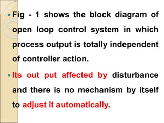
- 65. Fig - 1 shows the block diagram of open loop control system in which process output is totally independent of controller action. Its out put affected by disturbance and there is no mechanism by itself to adjust it automatically.
- 67. Practical Examples of Open Loop Control System 1. Electric Hand Drier - Hot air (output) comes out as long as you keep your hand under the machine, irrespective of how much your hand is dried. 2. Automatic Washing Machine - This machine runs according to the pre-set time irrespective of washing is completed or not. 3. Bread Toaster - This machine runs as per adjusted time irrespective of toasting is completed or not. 4. Automatic Tea/Coffee Maker - These machines also function for pre adjusted time only. 5. Timer Based Clothes Drier - This machine dries wet clothes for pre-adjusted time, it does not matter how much the clothes are dried. 6. Light Switch - Lamps glow whenever light switch is on irrespective of light is required or not. 7. Volume on Stereo System - Volume is adjusted manually irrespective of output volume level.
- 68. A very simple introductory example of an open-loop system is that of the clothes washing machine as shown in the block diagram bellow. Here, the reference signal r(t) designates the various operating conditions that we set on the ‘‘programmer,’’ such as water temperature, duration of various washing cycles, duration of clothes wringing, etc. These operating conditions are carefully chosen so as to achieve satisfactory clothes washing.
- 69. The controller is the ‘‘programmer,’’ whose output u(t) is the control signal. This control signal is the input to the washing machine and forces the washing machine to execute the desired operations reassigned in the reference signal r(t), i.e., water heating, water changing, clothes wringing, etc. The output of the system y(t) is the ‘‘quality’’ of washing, i.e., how well the clothes have been washed. It is well known that during the operation of the washing machine, the output (i.e., whether the clothes are well washed or not) it not taken into consideration. The washing machine performs only a series of operations contained in u(t) without being influenced at all by y(t). It is clear that here u(t) is not a function of y(t) and, therefore, the washing machine is a typical example of an open-loop system. Other examples of open-loop systems are the electric stove, the alarm clock, the elevator, the traffic lights, the worldwide telephone communication system, the computer, and the Internet
- 70. Advantages of Open Loop Control System Simple in construction and design. 2. Economical. 3. Easy to maintain. 4. Generally stable. 5. Convenient to use as output is difficult to measure. Disadvantages of Open Loop Control System 1. They are lower inaccurate. 2. They are unreliable. 3. Any change in output cannot be corrected automatically.
- 71. Closed Loop Control System Control system in which the output has an effect on the input quantity in such a manner that the input quantity will adjust itself based on the output generated is called closed loop control system. Open loop control system can be converted in to closed loop control system by providing a feedback. This feedback automatically makes the suitable changes in the output due to external disturbance. In this way closed loop control system is called automatic control system. Prepared by Oumer
- 72. Figure below shows the block diagram of closed loop control system in which feedback is taken from output and fed in to input
- 74. Example of closed loop control system Prepared by Oumer Hassen
- 75. Advantages of Closed Loop Control System 1. Closed loop control systems are more accurate even in the presence of non-linearity. 2. Highly accurate as any error arising is corrected due to presence of feedback signal. 3. Bandwidth range is large. 4. Facilitates automation. 5. The sensitivity of system may be made small to make system more stable. 6. This system is less affected by noise.
- 76. Disadvantages of Closed Loop Control System 1. They are costlier. 2. They are complicated to design. 3. Required more maintenance. 4. Feedback leads to oscillatory response. 5. Overall gain is reduced due to presence of feedback. 6. Stability is the major problem and more care is needed to design a stable closed loop system.
- 77. Components of Control Loops Primary element/sensor Recorder Controller Correcting element/final control element Actuator Transducer Converter Transmitter Signal Indicator
- 78. TRANSDUCERS AND CONVERTERS A transducer converts any form of energy into another form. In electrical instrumentation field Transducers are devices which converts a physical variable into electrical signals. Another name transducers are Pick-ups. A transducer is a device that translates a mechanical signal into an electrical signal. For example, inside a capacitance pressure device, a transducer converts changes in pressure into a proportional change in capacitance.
- 79. A converter is a device that converts one type of signal into another type of signal. For example, a converter may convert current into voltage or an analog signal into a digital signal. In process control, a converter used to convert a 4–20 mA current signal into a 3–15 psig pneumatic signal (commonly used by valve actuators) is called a current-to-pressure
- 80. Common electroacoustic transducers: Loudspeaker – Converts an electrical signal into sound Microphone – Converts sound waves in air into an electrical signal electrical signal Hydrophone - Converts sound waves in water into an electrical signal. Common electromagnetic transducers: Magnetic cartridge – Converts motion in a magnetic field into an electrical energy
- 81. Electromechanical Transducers Strain gauge – Converts the deformation(strain) of an object into electrical resistance Galvanometer– Converts the electric current of a coil in a magnetic field in movement Generators – Converts mechanical energy (motion) into electrical energy. Motor – Converts electrical energy into mechanical energy (graphic below)
- 82. Photoelectric Transducers: Cathode ray tube (CRT) –Converts electrical signals into light energy for a visual output (graphic above) Light bulb –Converts electrical energy into visible light and heat (explained in next section) Photodiode - Converts light energy into electrical energy Thermoelectric Transducers: Thermocouple – Converts heat energy into electrical energy Temperature sensitive resistor (Thermistor) – a variable resistor affected by temperature changes (heat energy to electrical energy)
- 83. Photovoltaic Transducers Sandwich design of a metal base plate and a thin transparent metallic layer with a semiconductor material in between Light strikes barrier between transparent metal layer and semiconductor material, and a voltage is generated Most widely used application of photovoltaic cell is the light exposure meter in photographic work
- 84. Converter A converter is a device that converts one type of signal into another type of signal. For example, a converter may convert current into voltage or an analog signal into a digital signal. In process control, a converter used to convert a 4–20 mA current signal into a 3–15 psi pneumatic signal (commonly used by valve actuators) is called a current-to-pressure converter.
- 85. Transmitters: Transmitters are devices that convert the signal into a standard signal that can be transmittable through the control loop and the parameters can be monitored remotely. • Pressure transmitters • Flow transmitters • Temperature transmitters • Level transmitters • Analytic transmitters
- 86. TRANSMITTERS A pressure transducer, often called a pressure transmitter, is a transducer that converts pressure into an analog electrical signal. Pressure applied to the pressure transducer produces a deflection of the diaphragm which introduces strain to the gages. Flow transmitters provide electrical outputs that are proportional to flow inputs. They use flow meters to measure the flow of liquids and gases. Flow transmitters use three basic types of meters: mass, volumetric, and velocity.
- 87. Temperature transmitter is an electrical instrument, which interfaces the temperature sensor to isolate, amplify, filter noise and convert the signal from the sensor to send it to the control device. It is a tool to help measure and alert temperature changes. Level transmitters provide continuous level measurement over the range of the system rather than at a single point and produce an output signal that directly correlates to the level within a vessel. The output signal generated can be used to display the depth or to actuate control functions.
- 88. Signals There are three kinds of signals that exist for the process industry to transmit the process variable measurement from the instrument to a centralized control system. ◦ Pneumatic signal ◦ Analog signal ◦ Digital signal
- 89. Pneumatic signal: Pneumatic signals are signals produced by changing the air pressure in a signal pipe in proportion to the measured change in a process variable. The common industry standard pneumatic signal range is 3–15 psig. The 3 corresponds to the lower range value (LRV) and the 15 corresponds to the
- 90. Analog Signals The most common standard electrical signal is the 4–20mA current signal. With this signal, a transmitter sends a small current through a set of wires. The current signal is a kind of gauge in which 4mA represents the lowest possible measurement, or zero, and 20mA represents the highest possible measurement. Other common standard electrical signals include the 1–5 V (volts) signal and the pulse output. 90
- 91. Analog Signals For example, imagine a process that must be maintained at 100 °C. An RTD temperature sensor and transmitter are installed in the process vessel, and the transmitter is set to produce a 4 mA signal when the process temperature is at 95 °C and a 20 mA signal when the process temperature is at 105 °C. The transmitter will transmit a 12 mA signal when the temperature is at the 100 °C Set-point. 91
- 92. As the sensor’s resistance property changes in response to changes in temperature, the transmitter outputs a 4–20 mA signal that is proportionate to the temperature changes. This signal can be converted to a temperature reading or an input to a control device, such as a burner fuel valve.
- 93. Digital signals Digital signals are the most recent addition to process control signal technology. Digital signals are discrete levels or values that are combined in specific ways to represent process variables and also carry other information, such as diagnostic information. The methodology used to combine the digital signals is referred to as protocol. 93
- 94. INDICATORS indicator is a human-readable device that displays information about the process. Indicators may be as simple as a pressure or temperature gauge or more complex, such as a digital read-out device. Some indicators simply display the measured variable, while others have control buttons that enable operators to change settings in the field. 94
- 95. RECORDERS A recorder is a device that records the output of a measurement devices. Many process manufacturers are required by law to provide a process history to regulatory agencies, and manufacturers use recorders to help meet these regulatory requirements. In addition, manufacturers often use recorders to gather data for trend analyses. By recording the readings of critical measurement points and comparing those readings over time with the results of the process, the process can be improved. 95
- 96. Different recorders display the data they collect differently. Some recorders list a set of readings and the times the readings were taken; others create a chart or graph of the readings. Recorders that create charts or graphs are called chart recorders.
- 97. CORRECTING ELEMENTS/FINAL CONTROL ELEMENTS The correcting or final control element is the part of the control system that acts to physically change the manipulated variable. In most cases, the final control element is a valve used to restrict or cut off fluid flow, but pump motors, louvers (typically used to regulate air flow), solenoids, and other devices can also be final control elements. Final control elements are typically used 97
- 98. For example, a final control element may regulate the flow of fuel to a burner to control temperature, the flow of a catalyst into a reactor to control a chemical reaction, or the flow of air into a boiler to control boiler combustion. In any control loop, the speed with which a final control element reacts to correct a variable that is out of set point is very important. Many of the technological improvements in final control elements are related to improving their response time.
- 99. ACTUATORS An actuator is the part of a final control device that causes a physical change in the final control device when signaled to do so. The most common example of an actuator is a valve actuator, which opens or closes a valve in response to control signals from a controller. Actuators are often powered pneumatically, hydraulically, or electrically. Diaphragms, bellows, springs, gears, hydraulic pilot valves, pistons, or electric motors are often parts of an actuator system. 99
- 100. CONTROLLERS A controller is a device that receives data from a measurement instrument, compares that data to a programmed set-point, and, if necessary, signals a control element to take corrective action. Local controllers are usually one of the three types: pneumatic, electronic or programmable. Controllers also commonly reside in a digital control system. 100
- 101. CONTROLLERS Controllers may perform complex mathematical functions to compare a set of data to set-point or they may perform simple addition or subtraction functions to make comparisons. Controllers always have an ability to receive input, to perform a mathematical function with the input, and to produce an output signal. ON/OFF controller (PLC), PID, Fuzzy controller. . .are type of controller. 101
- 102. Programmable Logic Controller for Process Control System CONTROLLER DESIGN 102
- 103. Prepared by Shimels Chekol 103 Prepared by Oumer Hassen
- 104. 1. Design a PLC program to control the level of a water storage tank by turning a discharge pump ON and OFF based on Low and High levels. Logic Description : Auto :if Auto Mode selected in Local Control Panel, then pump will be logically controlled based on Low Level Switch and High Level Switch Manual :if Manual Mode Selected in Local Control Panel, then irrespective of Low Level Switch & High Level Switch Status, Pump will be controlled manually using ON/OFF button in Local Control 104
- 105. When the water level reaches low level then pump will be stopped. if the level of the water reaches high point, the pump will started so that the water can be drained and thus lowering the level. Indication Panel : This panel contains LED’s to show the status of the water level control. It has Pump Running, Low Level & High Level Signals If pump is running then the Pump Running status lamp will be ON. then, if Low Level Switch activated then Low Level Status lamp will be ON. if High Level Switch activated then High Level Status lamp will be ON. 105
- 106. Controller; Programmable Logic Controller (PLC) Hardware 1. Input device of controller 2. Output device of controller Stop push button =I1 Start push button=I2 Low level sensor=I3 High level sensor=I4 Pump motor =Q1 Pump running indicator lamp=Q2 Low level indicator lamp=Q3 High level indicator lamp=Q4 106
- 107. Design PLC controller for automatic water level control system 107 Prepared by Oumer
- 108. Level Sensors Prepared by Shimels Chekol 108