SlideShare a Scribd company logo
6.0 VERTICAL TRANSPORTATION SYSTEM
6.1 Introduction & Functions
MECHANICAL TRANSPORTATION
Building Services (BLD 60903) March 2017 1
Vertical Transportation Systems refers to the service component within a building which enables
us to travel vertically between floors much quicker and effortlessly. Throughout the case study
conducted on the Summit Mall in USJ, it was concluded that the mall has 3 forms of mechanical
transportation system. The Escalators, Inclined Travelators and Elevators.
6.2 Elevators
An elevator is a transportation device used to move goods and people vertically between floors
(levels, decks) of a building, vessel, or other structure. Elevators usually provide access for the
elderly and disable through the floors of modern offices and public buildings.
In present day, there are 2 main types of elevators that are commonly used in public buildings,
that is the Electric elevators and the (i) hydraulic elevators. However, the electric elevators are
classified into 2 based on the variations, the (ii) Traction with Machine Room elevators, and
(ii) Machine room-less Traction Elevators.
Hydraulic Elevator Traction With Machine Room Machine Room-less Traction
6.2.1 Type of Elevator in Summit USJ
Summit USJ Subang uses KONE Ecospace machine room-less (MRL) elevators, which do not
require a machine room above the elevator shafts. Due to the size of KONE EcoDisc hoisting
Fluid Tank
(Controller)
Piston
MECHANICAL TRANSPORTATION
Building Services (BLD 60903) March 2017 2
Diagram 6.2 Components of an
Machine Room-less elevator device
motor, the elevators do not need a separate machine room. The reduction of the sheave size,
alongside a more compact redesigned machine allows the machine to be assembled within the
hoistway itself, saving valuable floor space and the need of a bulky machine room. There is no
need for a control room as the KONE EcoSpace control and logic components fit inside the wall
of the top elevator landing. Most machine room-less elevators are used for low to mid rise
buildings. Machine room-less elevators in mid-rise buildings usually serves up to 20 floors. They
are comparable to geared traction elevators in terms of initial and maintenance costs, but they
have relatively low energy consumption
compared to geared elevators.
Diagram 6.1 KONE Ecospace
Machine Room-less (MRL)
Elevator in Summit USJ
MECHANICAL TRANSPORTATION
Building Services (BLD 60903) March 2017 3
Diagram 6.6 The
interior of a Fire
Fighting Lift
6.2.1.1PassengerLifts & Firefighting Lift
In USJ Summit building, there are 7 firefighting lift and 24 passengers lift in total. The Passenger
lift are capable of transporting 25 persons at a time with the weight limit of 1705 kg. The
passenger lifts are equipped with the fireman switch. When the switch is turned on, elevators are
directed to the fire recall floor. Elevators traveling away are then reversed back to the designated
floor without stopping. Upon reaching, passengers are able to exit the elevator and building
safely. The elevators are then removed from normal service. Once removed from normal service,
the elevators will no longer accept car or hall calls. This mode of Fire Service allows firefighters
to continue to utilize the elevator to rescue people from other floors.
On the other hand, the firefighting lift is an elevator within the firefighting shaft with dual power
supply and is capable of being commandeered by the fire service department. The firefighting
lifts are capable of transporting an approximate amount of 27 people, with the weight limit of
1835 kg.
Diagram 6.3 The exterior
and interior view of the
Passenger Lifts
Diagram 6.4 The Fireman switch
installed on the side façade of the
elevator
Diagram 6.5 The
firefighting lifts in
Summit USJ are
labelled with red
sign stating ‘Lif
Bomba’
MECHANICAL TRANSPORTATION
Building Services (BLD 60903) March 2017 4
6.2.2 ElevatorComponents
6.2.2.1ElevatorCar
Elevator Car is the cabin that travels between different landing floors carrying passengers and
goods, it is usually a heavy steel frame surrounding a cage of metal panels, mounted on a
platform within an enclosed space. The Elevator Car type used in Summit USJ is the Normal
Cabin elevator, which has only one opening. The elevator cabin has weight limit of 1705 kg, a
maximum of 25 pax.
Diagram 6.7 The typesof elevator cabin used in
Summit USJ & the required dimensions for various
lift
Diagram 6.8 The components within an
elevator car
(i) Infrared DoorSensor
MECHANICAL TRANSPORTATION
Building Services (BLD 60903) March 2017 5
Infrared sensors are installed in Summit Mall’s elevator to detect passengers on the doorway,
preventing the doors from closing which may any accidents to happen. Elevator door will reopen
and hold for a specific period of time until the passenger leaves the doorway. Nudge mode of
elevator will be initiated if the lift door has been blocked more than the set period of time to
inform the passengers that the door is closing with a continuously beep. Door sensors in
elevators in Summit work with independent power supply to make sure it works.
Diagram 6.9 Infrared Door Sensor in Summit USJ
(ii) Buttons, Key Controls and System Controls
In Summit, all compulsory buttons in each lift car are provided on the control panels such as the
hall button, floor request buttons, open and close door buttons, emergency stop button,
emergency bell button and the registration panels. The key controls of the elevator are located
MECHANICAL TRANSPORTATION
Building Services (BLD 60903) March 2017 6
below the floor request buttons to allow various functions to be turned on and off by the
management staffs or firefighters who hold the key to carry out operations like maintenance, fire
department control, elevator on or off etc. On the other hand, system controls in Summit are
located in elevator control room to control its operation during daytime or night.
Diagram 6.10 Elevator at Summit (left) Illustration of the buttons and controls (right)
MECHANICAL TRANSPORTATION
Building Services (BLD 60903) March 2017 7
6.2.2.2KONE Ecodisc Hoisting Motor
Diagram 6.10 Ecodisc Motor installed within hoistway
KONE’s machine room-less (MRL) technology eliminates the need for a machine or control
room by attaching its KONE Ecodisc Hoisting Machine to the guard rail, while placing all
controls and logic components within the confined space of the hoist way. The hoisting motor is
capable of transporting people and goods to a maximum distance of 76m and a travelling speed
of 152m per minute.
6.2.2.3KONE EcospaceController
An Elevator Controller is a system to control the
elevators, either manual or automatic. The control
system used in USJ Summit Buildings are of KONE
Ecospace controller, which provides advantages in
space saving and simplified installation. There is no
need for a controller room as the KONE Ecospace
Controller and other logic components are fit inside
the wall of the top elevator landing. This speeds up
the installation process, since no scaffolding or crane
is needed.
Diagram 6.11 Controller installed within the wall of top
landing
6.2.2.4EscalatorDriving Sheave
MECHANICAL TRANSPORTATION
Building Services (BLD 60903) March 2017 8
Diagram 6.12 Sheave as a gear for traction elevator
An escalator sheave is a deeply grooved pulley attached to the elevator’s machine. Compared to
the conventional traction elevators, the driving sheave of KONEMachine Room-less elevator is
reduced in size. While the lift rates are slower than in a typical gearless elevator, the gear
reduction offers the advantage of requiring a less powerful motor to turn the sheave. Optimally
shaped magnets are attached directly to the sheave to produce a gearless motor with smooth,
noiseless operation.
6.2.2.5Polyurethane-CoatedSteelCable
Diagram 6.13 Polyurethane-Coated Steel Cables
The KONE machine room-less elevators do not use traditional steel cables. Instead,
Polyurethane-Coated Steel Cables have replaced them, providing unrivalled elevator eco-
efficiency, reliability and durability, while also improving elevator performance. It eliminates the
disadvantages of existing steel ropes – high energy consumption, rope stretch, large moving
masses, and downtime caused by building sway. These cables are only 3mm thick, therefore
allowing the KONE elevators to have smaller sheave.
6.2.2.6 Counter Weight
A counterweight carried by and elevator cable to balance the
weight of an elevator cab; the counterweight travels
MECHANICAL TRANSPORTATION
Building Services (BLD 60903) March 2017 9
downward when the cab travels upwards and vice versa. The
counterweight is usually steel plates stacked within a frame.
Having a counterweight eases the motor to raise and lower
the car, provided that there is sufficient counterweight top
clearance the car bottom run by is recommended to be
somewhere in between 150mm to 600mm.
Diagram 6.14 Counterweight balancing the elevator and its load
6.2.2.7Guide Rails
Guide Rails in an elevator are steel tracks in the form of a ‘T’
that run the length of the hoist way. The guard rails have
guiding surface to guide and direct the course of travel of an
elevator car and elevator counterweights. They are usually
mounted to the sides of the hoist way. The guide rails are
fixed to the hoist way by means of steel brackets.
Diagram 6.15 Brackets to fix the elevator cars onto the guard rails
6.2.3 Operation of Elevator System
6.2.3.1 Type of Elevators Control System
In Summit, the elevators are in the setting of two-car selective collective operation. This
operating system is the most common application in buildings for two cars under group control
as it remembers all car calls and proceed to the destination in one direction then reverse its
MECHANICAL TRANSPORTATION
Building Services (BLD 60903) March 2017 10
direction again. In each escalator landing, the up and down buttons are provided except in the
highest and lowest floor of the building. There are car buttons provided on car operating panel in
each elevator cars. The operation of elevator begins when lift users press hall call button to
register a hall call, it will initiate one of the two cars to be assigned to the lift lobby. After users
enter the lift car, it will respond to the next car call registered by other users at any lift lobby. If
all hall calls and car calls have been answered in which the direction of the car is traveling, the
car will then travel in an opposite direction to receive any halls calls and car calls assigned to it.
Users are required to press hall call and car call buttons by hand in order to operate the cars.
MECHANICAL TRANSPORTATION
Building Services (BLD 60903) March 2017 11
6.2.3.2SafetyMechanisms in Elevators
Diagram 6.16 Main break in Elevator
The safety mechanism found in elevators is the main break located directly on the shaft. The
elevators start to slow down by the dynamic braking of the motor. The main brake is then
operated to clamp down on the brake drum, this will hold the car still at the floor. There is a dual
safety device that is used to stop the car automatically in case the elevator over-speeds.
Diagram 6.17 Overspeed Governor in Elevator
The over speed governor will cut the power supply towards the motor and activates the brakes if
the speed limit of the escalator is exceeded. This will slow down the elevator car significantly.
The governor will trigger another two safety rail clams if the speed of the escalator remains. The
rail claims are located at the bottom of the elevator car with one at each side. Spring and rubber
buffers are placed in the pit to aid and act as a cushion for the falling car.
6.2.4 UBBL Requirements & Regulations for Elevator
MECHANICAL TRANSPORTATION
Building Services (BLD 60903) March 2017 12
Uniform Building By-Laws 1984 Analysis
Section 124:
Lift
For all non-residential buildings exceeding 4 storeys
above or below the main access level at least one lift
shall be provided.
Section 151:
Ventilation to Lift Shafts
Where openings to lift shafts are not connected to
protected lobbies, such lift shafts shall be provided
with vents of not less than 0.09 square metre per lift
located at the top of the shafts. Where the vent does
not discharge directly to the open air the lift shafts
shall be vented to the exterior through a duct of the
required FRP as for the lift shafts.
Section 153
Smoke Detectors for Lift Lobbies
Summit mall consisting of 5 floors
is installed with 24 Passenger Lifts
& 7 Fire Fighting Lifts.
Two fans are installed to each lift
device on the top part of the shaft.
Photoelectric smoke detectors are
MECHANICAL TRANSPORTATION
Building Services (BLD 60903) March 2017 13
1. All lift lobbies shall be provided with smoke
detectors.
2. Lift not opening into a smoke lobby shall not use
door reopening devices controlled by light beam
or photo-detectors unless incorporated with a force
close feature which after thirty seconds of any
interruption of the beam causes the door to close
within a preset time.
Section 154:
Emergency mode of operation in the event of
mains power failure
1. On failure of mains power all lifts shall return in
sequence directly to the designated floor,
commencing with the fire lifts, without answering
any car or landing calls and park with doors open.
installed at every lift lobbies at
Summit Mall.
During power failure, all lifts at
Summit Mall will automatically
stop at ground floor with doors
open.
6.3 Escalators
An escalator is a vertical transportation device in the form of a moving staircase – a conveyor
which carries people between levels of a building. It consists of a motor-driven chain of
individually linked steps which remain horizontal, allowing the user to stand still while
transporting user to the next floor. The escalator provides an immediate means of transportation,
MECHANICAL TRANSPORTATION
Building Services (BLD 60903) March 2017 14
being able to convey continuously to transport a large number of
people. An elevator can be reversible to suit the main flow of traffic
during peak hours. The escalators used in Summit Mall USJ are of the
brand KONE.
Location of Escalators
In Summit USJ, the escalators are positioned next to the
main entrance at ground floor and center part of the upper
floors to permit efficiency of transportation and circulation.
The escalators allow easy access through the main
circulation of the retail podium which lead people towards
promotional space or alongside display of merchandise at
Summit.
Diagram 6.18 Escalators in Summit USJ
Escalator Inclination and Speed
Inclination of the escalators in Summit USJ is 30°
which provides the maximum safety and
comfortability to the user. They are running a speed
of 0.5 meters per second at Summit which is an
optimum speed to retain shoppers at the mall for a
longer period of time.
Diagram 6.19 Side Elevation & Front elevation of escalator
6.3.1 Arrangement of Escalators
The elevators in Summit Mall USJ is positioned in a multi-level parallel
arrangement. The escalators are used to create a connection between ground floor
to the fourth floor of the retail podium. Multi-level parallel arrangement is used
due to economical as there is no inner layer of lateral claddings required which is
MECHANICAL TRANSPORTATION
Building Services (BLD 60903) March 2017 15
covered by another escalator beside. The mall utilizes this arrangement as one of
the sales strategies since passengers have to make a short detour in order to access
to next escalator to go up or down. Displays of merchandise are strategically
located along the way to increase sales in Summit. Sometimes, Summit will
reverse the travelling direction of escalator if the traffic flow is high during peak
season. However, the direction of users’ traffic will be reversed to make a big U-
turn in order to access to another escalator going up or down. Overall traveling
time of passengers between floors will be increased.
Diagram 6.20 Multi-Level Parallel Arrangement of escalators at Summit Mall
6.3.2 Components of Escalators
MECHANICAL TRANSPORTATION
Building Services (BLD 60903) March 2017 16
MECHANICAL TRANSPORTATION
Building Services (BLD 60903) March 2017 17
6.3.2.1 Upper and Lower Landing Platforms
These two platforms house the curved sections of the tracks, including the gears and motors that
drive the stairs. The top platform contains the motor assembly and the main drive gear, while the
bottom holds the step return idler sprockets. These sections also anchor the ends of the escalator
truss.
Diagram 6.21 Floor Plate and Comb Plate of escalator
Each of the platforms contain a floor plate and a comb plate. The floor plate provides a place for
the passengers to stand before they step onto the moving stairs. This plate is flush with the
finished floor and is removable to allow easy access to the machinery below. The comb plate is
the piece between the stationary floor plate and the moving step. It is so named because its edge
has a series of cleats that resemble the teeth of a comb. These teeth mesh with matching cleats on
the edges of the steps. This design is necessary to minimize the gap between the stair and the
landing, which helps prevent objects from getting caught in the gap.
6.3.2.2 Escalator Truss
Comb Plate
Floor Plate
MECHANICAL TRANSPORTATION
Building Services (BLD 60903) March 2017 18
An escalator truss is the structural frame of an escalator which consists of, the lower section,
incline section and the upper section. It is a hollow metal structure that connects the lower and
upper landings. Both ends of the elevator truss are attached to the top and bottom landing
platforms through steel or concrete supports. The structural steel truss members are designed to
carry the entire load of the escalator equipment and the steel covering. To maintain close
operating tolerances, the entire structure must rigid enough but at the same time tolerating
building shift and vibration because of a built-in system of shift- plates and Teflon pads.
Diagram 6.22 Elevatortruss connected to the platforms at both ends
MECHANICAL TRANSPORTATION
Building Services (BLD 60903) March 2017 19
6.3.2.3 Escalator Tracks
The track system is assembled into the truss of escalator to guide the step chain, which endlessly
pulls the steps from the bottom platform to the top platform in an endless loop. The track system
carries the steps down along the bottom of the truss until they reach the bottom landing, where
they pass through another curved section of track before departing from the bottom landing. At
this point, the tracks separate and the steps once again assume a staircase configuration. This
configuration forces the back of one step to be at a 90-degree angle relative to the step behind it.
This right angle bends the steps into a shape resembling a staircase. This cycle is repeated
continuously.
Diagram 6.23 Components of an EscalatorTrack
MECHANICAL TRANSPORTATION
Building Services (BLD 60903) March 2017 20
6.3.2.4 Escalator Steps
The escalators steps are an arrangement of solid, one piece, die-cast aluminum or steel steps. The
steps are linked by a continuous metal chain that forms a closed loop. The front and back edges
of the steps are connected to a pair of wheels each. The front wheels have shorter axles to fit into
the narrower front track whereas the rear wheels are set further apart to fit into the back track.
Normally, yellow demarcation lines may be added to clearly indicate the steps edges.
Diagram 6.24 Components within an escalator step
Step Plate (Thread)
Demarcation Lines
Axle Slot
Frame Yoke Step Wheel
(Trailing Wheel)
Step Riser
Step Hook
(T BAR)
MECHANICAL TRANSPORTATION
Building Services (BLD 60903) March 2017 21
6.3.2.5 Handrail
A Handrail on the escalators provides a convenient handhold for the users while they are get onto
the escalator. In an escalator, the handrail is drawn along its track by a chain that is connected to
the main drive gear by a series of pulley.
Diagram 6.25 Components within the handrails
6.3.2.6 Escalator Balustrade
A Balustrade consists of the handrail and the exterior supporting structure of the escalator. The
balustrade can also refer to the skirt panels, individual interior panels, and deck covers of the
escalator. Each interior balustrade panel section is removable to allow ease of access towards the
escalator interior for maintenance and component replacement.
Diagram 6.26 Front elevation of Escalatorbalustrade and its components
6.3.2.7Internal Drive Machine
Handrail
New el
Handrail
Guide
MECHANICAL TRANSPORTATION
Building Services (BLD 60903) March 2017 22
Diagram 6.27 View of an Internal Drive Machine used in escalator (Left) Components within an
Internal Drive Machine(Right)
A Drive Machine is used in escalator to drive the pinion gear or the main drive chain which may
directly or indirectly drive the Handrail Drive System. In summit USJ, elevators with Internal
Drive machine is installed. The machine is located at the upper landing, installed inside the truss
between the step bands or at the top pit, the machine will employ a motor to gearbox drive with a
direct drive axle connection. Normally in an Internal Drive Machine, a separated dual drive
machine within the step band is not uncommon with one machine used to directly drive the step
chains located a few feet below the upper incline and one above the lower incline.
MECHANICAL TRANSPORTATION
Building Services (BLD 60903) March 2017 23
6.3.2.8Braking Systems
Diagram 6.28 Components within the Brake systemof Escalator
The braking system uses a pawl connected to one end of the main drive shaft to engage a notch
wheel with brake linings on both faces. The brake lining wheel is slotted between the handrail
1st drive sprocket and the step chain sprocket. A guide shoe lever is connected onto the opposite
end of the main drive shaft. It is normally supported by the drive chain and when the chain
breaks, the shoe drops and turns the shaft. The drive shaft brake pawl moves into the ratchet
wheel and stops the escalator when the guide shoe drops.
MECHANICAL TRANSPORTATION
Building Services (BLD 60903) March 2017 24
6.3.2.9 Safety Devices
(i) Emergency Stop Button (E-STOP)
An emergency stop button is provided at both the upper and lower landing of the escalator. This
covered button enables anyone to stop the escalator immediately in the event of an emergency.
Lifting the cover of the emergency stop button will trigger an alarm for five minutes or until the
escalator is restarted. To restart an elevator, release the Emergency Stop Button by using the
normal start-up procedure.
(ii) Caution Sign Boards & LED indicator
Caution sign boards can be found at the glass panel of the top and bottom landing of every
escalator at Summit Mall which must be noticeable by the users. The signs are in standard format
with identical size, wording and colors. On the other hand, green and red LED lights are
provided at the escalators to inform the users whether the escalators are going up or down.
6.4 Inclined Travelator
An Inclined travelator is a slow-moving conveyor mechanism that transports people or goods
MECHANICAL TRANSPORTATION
Building Services (BLD 60903) March 2017 25
across an inclined plane over a short to medium distance. Inclined travelators are usually
provided in shopping malls where shopping carts or trolleys need to be transported to different
levels. By transporting people continuously non-stop, travelators ensure smooth flow of people
through the building and has the capacity to handle high traffic. Summit Mall in USJ uses KONE
Inclined Travelators. The Inclined travelators in Summit are located next to Giant Mart to
provide an easy access to basement floors after shopping. It allows the users to bring their
shopping trolleys to their cars at basement levels.
Diagram 6.29 Travelator located at the lowerground floorfortransportation of goods to the basement
Diagram 6.30 Dimensions of Travelator used in Summit USJ
6.4.1 Safety equipment
(i) Handrail and Headroom Clearance
MECHANICAL TRANSPORTATION
Building Services (BLD 60903) March 2017 26
In Summit Mall USJ, the measurement for headroom measured vertically from the step nose line
and landing plates is 2500 mm which fulfilled the minimum requirement. The distance between
handrail and adjacent surfaces such as columns in Summit is 400mm. It is to ensure passengers
are free from any potential risk such as knocking some harmful object hence causing any
injuries.
(ii) Protective Barriers
Suitable structural measures are installed at the both ends of the inclined travelators to prevent
people from taking rides in between the escalators. These protective barriers act as guards that
are provided on the balustrading of travelator wherever necessary.
Diagram 6.31 Anti-Slide device installed to avoid sliding of objects or people
MECHANICAL TRANSPORTATION
Building Services (BLD 60903) March 2017 27
(iii) Head Guards
These head guards, known as apex guard’s aids in the
safety requirement of travelators, preventing
passengers’ heads getting trapped in between the
balustrade and the building structure. This might cause
unwanted accident in the mall.
Diagram 6.32 Head guards with striking red stripes
(iv) Emergency Stop Device
The emergency stop device is provided at both the
upper and lower landing of the Travelator. This covered
button enables users to stop the travelator immediately
in the event of an emergency.
Diagram 6.33 Emergency Stop Device installed at the side
of handrails to ease user triggering the brakes

More Related Content

PPT
vertical-transportation (mechanical)
PPTX
Vertical transportation important
PDF
Architectural interior case study on student activity center kuet becm
PPTX
Escalators
PDF
building services -Lift's and escalators
PPTX
Lift.escalator & moving walk
PPTX
Intro to auditorium design
PDF
Vertical Transportation Systems in Buildings by Ramesh Nayaka
vertical-transportation (mechanical)
Vertical transportation important
Architectural interior case study on student activity center kuet becm
Escalators
building services -Lift's and escalators
Lift.escalator & moving walk
Intro to auditorium design
Vertical Transportation Systems in Buildings by Ramesh Nayaka

What's hot (20)

PPTX
Elevators and excelarators
PPTX
Escalators
PPTX
Bulk active
PDF
Architectural acoustics
PPTX
Elevators & Escalators
PPTX
Electrical Systems in a Building
PPTX
Shopping centers
PPTX
Tensile structures
PDF
High rise structure & core
DOC
BS 2 Escalators arrangement
PPTX
Food Court Case Study.pptx
PPTX
Standards Requirement For Multiplexes And Bye Laws Of NOIDA
PDF
Green Buildings-passive heating techniques
PDF
Lifts and Escalators (Schindler)
PPT
Residential cum Commercial Building
PDF
Architectural Case Study
PDF
Building service final pdf
PPTX
Parking final
PPTX
Kinetic structures | B.arch
PPT
Elevators and excelarators
Escalators
Bulk active
Architectural acoustics
Elevators & Escalators
Electrical Systems in a Building
Shopping centers
Tensile structures
High rise structure & core
BS 2 Escalators arrangement
Food Court Case Study.pptx
Standards Requirement For Multiplexes And Bye Laws Of NOIDA
Green Buildings-passive heating techniques
Lifts and Escalators (Schindler)
Residential cum Commercial Building
Architectural Case Study
Building service final pdf
Parking final
Kinetic structures | B.arch
Ad

Viewers also liked (8)

PDF
In Mall Escalators, Travelators & Arches Media Presentation 2013
PPT
BS 2 Lift presentation 4
PPTX
lift ppt
PPTX
Walkalator
PDF
Travelator - Revolutionizing European Travel
PPTX
PPT
Lift Design
In Mall Escalators, Travelators & Arches Media Presentation 2013
BS 2 Lift presentation 4
lift ppt
Walkalator
Travelator - Revolutionizing European Travel
Lift Design
Ad

Similar to Vertical transportation system (20)

PDF
DEKISH ELEVATORS Private Ltd brochure new.pdf
PDF
DESIGN & MANUFACTURING OF WHEELCHAIR LIFTER
PDF
The design of vertical transportation systems
DOCX
Design of Elevator Controller using Verilog HDL
PDF
Catalogue thang máy Nexiez MR
PDF
Catalogue Thang máy Mitsubishi_Series-NEXIEZ-MR.pdf
PDF
Catalogue thang máy Nexiez MRL
PDF
Catalogue Thang máy Mitsubishi_Series-NEXIEZ-MRL.pdf
PDF
Irish Constuction Industry Magazine_Sept_2008_Cost Model_Lifts
DOCX
Final year project report on scissor lift
PDF
Catalogue thang máy Elenessa
PDF
Alternative system solutions for wheel loaders and other construction equipment
PPTX
Elevators notes 1.pptx
PPTX
STAIRS AND LIFTS IN ARCHIETCTURE
PPTX
3340903- UEE- UNIT-3 ELEVATOR.pptx
PPTX
LIFTD AND TRANSPORTATION .
PDF
45671574-design-validation-of-eot-crane.pdf
PDF
Catalogue thang máy Nexway High Speed
PPTX
Elevators and escalators
PDF
Regenerative Elevator With Backup Plan
DEKISH ELEVATORS Private Ltd brochure new.pdf
DESIGN & MANUFACTURING OF WHEELCHAIR LIFTER
The design of vertical transportation systems
Design of Elevator Controller using Verilog HDL
Catalogue thang máy Nexiez MR
Catalogue Thang máy Mitsubishi_Series-NEXIEZ-MR.pdf
Catalogue thang máy Nexiez MRL
Catalogue Thang máy Mitsubishi_Series-NEXIEZ-MRL.pdf
Irish Constuction Industry Magazine_Sept_2008_Cost Model_Lifts
Final year project report on scissor lift
Catalogue thang máy Elenessa
Alternative system solutions for wheel loaders and other construction equipment
Elevators notes 1.pptx
STAIRS AND LIFTS IN ARCHIETCTURE
3340903- UEE- UNIT-3 ELEVATOR.pptx
LIFTD AND TRANSPORTATION .
45671574-design-validation-of-eot-crane.pdf
Catalogue thang máy Nexway High Speed
Elevators and escalators
Regenerative Elevator With Backup Plan

More from yenweizheng (20)

DOCX
Urban comparative essay
DOCX
Wz synopsis
PPTX
Food & culture
PDF
Bscience report
PPTX
Bsci ii (1)
PPTX
Bsci ii
PDF
B tech final report pdf
PPTX
Transient
PDF
Proposal
PDF
Design brief
PDF
Column
PDF
Building structure
PDF
Service report
DOCX
Mechancal ventilatio
DOCX
Introduction of air conditioning system
DOCX
Fire protection system bservice
DOCX
Conclusion reference
DOCX
Introduction b services
PDF
Pj street essay.docx
DOCX
Team bunga raya final report
Urban comparative essay
Wz synopsis
Food & culture
Bscience report
Bsci ii (1)
Bsci ii
B tech final report pdf
Transient
Proposal
Design brief
Column
Building structure
Service report
Mechancal ventilatio
Introduction of air conditioning system
Fire protection system bservice
Conclusion reference
Introduction b services
Pj street essay.docx
Team bunga raya final report

Recently uploaded (20)

PDF
LNK 2025 (2).pdf MWEHEHEHEHEHEHEHEHEHEHE
PDF
Indian roads congress 037 - 2012 Flexible pavement
PDF
IGGE1 Understanding the Self1234567891011
PDF
Classroom Observation Tools for Teachers
PPTX
History, Philosophy and sociology of education (1).pptx
PPTX
1st Inaugural Professorial Lecture held on 19th February 2020 (Governance and...
PDF
Hazard Identification & Risk Assessment .pdf
PDF
GENETICS IN BIOLOGY IN SECONDARY LEVEL FORM 3
DOC
Soft-furnishing-By-Architect-A.F.M.Mohiuddin-Akhand.doc
PPTX
Introduction to Building Materials
PPTX
202450812 BayCHI UCSC-SV 20250812 v17.pptx
PDF
SOIL: Factor, Horizon, Process, Classification, Degradation, Conservation
PDF
Black Hat USA 2025 - Micro ICS Summit - ICS/OT Threat Landscape
PDF
A GUIDE TO GENETICS FOR UNDERGRADUATE MEDICAL STUDENTS
PDF
Trump Administration's workforce development strategy
PDF
1_English_Language_Set_2.pdf probationary
PDF
احياء السادس العلمي - الفصل الثالث (التكاثر) منهج متميزين/كلية بغداد/موهوبين
PDF
Complications of Minimal Access Surgery at WLH
PDF
What if we spent less time fighting change, and more time building what’s rig...
PDF
Weekly quiz Compilation Jan -July 25.pdf
LNK 2025 (2).pdf MWEHEHEHEHEHEHEHEHEHEHE
Indian roads congress 037 - 2012 Flexible pavement
IGGE1 Understanding the Self1234567891011
Classroom Observation Tools for Teachers
History, Philosophy and sociology of education (1).pptx
1st Inaugural Professorial Lecture held on 19th February 2020 (Governance and...
Hazard Identification & Risk Assessment .pdf
GENETICS IN BIOLOGY IN SECONDARY LEVEL FORM 3
Soft-furnishing-By-Architect-A.F.M.Mohiuddin-Akhand.doc
Introduction to Building Materials
202450812 BayCHI UCSC-SV 20250812 v17.pptx
SOIL: Factor, Horizon, Process, Classification, Degradation, Conservation
Black Hat USA 2025 - Micro ICS Summit - ICS/OT Threat Landscape
A GUIDE TO GENETICS FOR UNDERGRADUATE MEDICAL STUDENTS
Trump Administration's workforce development strategy
1_English_Language_Set_2.pdf probationary
احياء السادس العلمي - الفصل الثالث (التكاثر) منهج متميزين/كلية بغداد/موهوبين
Complications of Minimal Access Surgery at WLH
What if we spent less time fighting change, and more time building what’s rig...
Weekly quiz Compilation Jan -July 25.pdf

Vertical transportation system

  • 1. 6.0 VERTICAL TRANSPORTATION SYSTEM 6.1 Introduction & Functions
  • 2. MECHANICAL TRANSPORTATION Building Services (BLD 60903) March 2017 1 Vertical Transportation Systems refers to the service component within a building which enables us to travel vertically between floors much quicker and effortlessly. Throughout the case study conducted on the Summit Mall in USJ, it was concluded that the mall has 3 forms of mechanical transportation system. The Escalators, Inclined Travelators and Elevators. 6.2 Elevators An elevator is a transportation device used to move goods and people vertically between floors (levels, decks) of a building, vessel, or other structure. Elevators usually provide access for the elderly and disable through the floors of modern offices and public buildings. In present day, there are 2 main types of elevators that are commonly used in public buildings, that is the Electric elevators and the (i) hydraulic elevators. However, the electric elevators are classified into 2 based on the variations, the (ii) Traction with Machine Room elevators, and (ii) Machine room-less Traction Elevators. Hydraulic Elevator Traction With Machine Room Machine Room-less Traction 6.2.1 Type of Elevator in Summit USJ Summit USJ Subang uses KONE Ecospace machine room-less (MRL) elevators, which do not require a machine room above the elevator shafts. Due to the size of KONE EcoDisc hoisting Fluid Tank (Controller) Piston
  • 3. MECHANICAL TRANSPORTATION Building Services (BLD 60903) March 2017 2 Diagram 6.2 Components of an Machine Room-less elevator device motor, the elevators do not need a separate machine room. The reduction of the sheave size, alongside a more compact redesigned machine allows the machine to be assembled within the hoistway itself, saving valuable floor space and the need of a bulky machine room. There is no need for a control room as the KONE EcoSpace control and logic components fit inside the wall of the top elevator landing. Most machine room-less elevators are used for low to mid rise buildings. Machine room-less elevators in mid-rise buildings usually serves up to 20 floors. They are comparable to geared traction elevators in terms of initial and maintenance costs, but they have relatively low energy consumption compared to geared elevators. Diagram 6.1 KONE Ecospace Machine Room-less (MRL) Elevator in Summit USJ
  • 4. MECHANICAL TRANSPORTATION Building Services (BLD 60903) March 2017 3 Diagram 6.6 The interior of a Fire Fighting Lift 6.2.1.1PassengerLifts & Firefighting Lift In USJ Summit building, there are 7 firefighting lift and 24 passengers lift in total. The Passenger lift are capable of transporting 25 persons at a time with the weight limit of 1705 kg. The passenger lifts are equipped with the fireman switch. When the switch is turned on, elevators are directed to the fire recall floor. Elevators traveling away are then reversed back to the designated floor without stopping. Upon reaching, passengers are able to exit the elevator and building safely. The elevators are then removed from normal service. Once removed from normal service, the elevators will no longer accept car or hall calls. This mode of Fire Service allows firefighters to continue to utilize the elevator to rescue people from other floors. On the other hand, the firefighting lift is an elevator within the firefighting shaft with dual power supply and is capable of being commandeered by the fire service department. The firefighting lifts are capable of transporting an approximate amount of 27 people, with the weight limit of 1835 kg. Diagram 6.3 The exterior and interior view of the Passenger Lifts Diagram 6.4 The Fireman switch installed on the side façade of the elevator Diagram 6.5 The firefighting lifts in Summit USJ are labelled with red sign stating ‘Lif Bomba’
  • 5. MECHANICAL TRANSPORTATION Building Services (BLD 60903) March 2017 4 6.2.2 ElevatorComponents 6.2.2.1ElevatorCar Elevator Car is the cabin that travels between different landing floors carrying passengers and goods, it is usually a heavy steel frame surrounding a cage of metal panels, mounted on a platform within an enclosed space. The Elevator Car type used in Summit USJ is the Normal Cabin elevator, which has only one opening. The elevator cabin has weight limit of 1705 kg, a maximum of 25 pax. Diagram 6.7 The typesof elevator cabin used in Summit USJ & the required dimensions for various lift Diagram 6.8 The components within an elevator car (i) Infrared DoorSensor
  • 6. MECHANICAL TRANSPORTATION Building Services (BLD 60903) March 2017 5 Infrared sensors are installed in Summit Mall’s elevator to detect passengers on the doorway, preventing the doors from closing which may any accidents to happen. Elevator door will reopen and hold for a specific period of time until the passenger leaves the doorway. Nudge mode of elevator will be initiated if the lift door has been blocked more than the set period of time to inform the passengers that the door is closing with a continuously beep. Door sensors in elevators in Summit work with independent power supply to make sure it works. Diagram 6.9 Infrared Door Sensor in Summit USJ (ii) Buttons, Key Controls and System Controls In Summit, all compulsory buttons in each lift car are provided on the control panels such as the hall button, floor request buttons, open and close door buttons, emergency stop button, emergency bell button and the registration panels. The key controls of the elevator are located
  • 7. MECHANICAL TRANSPORTATION Building Services (BLD 60903) March 2017 6 below the floor request buttons to allow various functions to be turned on and off by the management staffs or firefighters who hold the key to carry out operations like maintenance, fire department control, elevator on or off etc. On the other hand, system controls in Summit are located in elevator control room to control its operation during daytime or night. Diagram 6.10 Elevator at Summit (left) Illustration of the buttons and controls (right)
  • 8. MECHANICAL TRANSPORTATION Building Services (BLD 60903) March 2017 7 6.2.2.2KONE Ecodisc Hoisting Motor Diagram 6.10 Ecodisc Motor installed within hoistway KONE’s machine room-less (MRL) technology eliminates the need for a machine or control room by attaching its KONE Ecodisc Hoisting Machine to the guard rail, while placing all controls and logic components within the confined space of the hoist way. The hoisting motor is capable of transporting people and goods to a maximum distance of 76m and a travelling speed of 152m per minute. 6.2.2.3KONE EcospaceController An Elevator Controller is a system to control the elevators, either manual or automatic. The control system used in USJ Summit Buildings are of KONE Ecospace controller, which provides advantages in space saving and simplified installation. There is no need for a controller room as the KONE Ecospace Controller and other logic components are fit inside the wall of the top elevator landing. This speeds up the installation process, since no scaffolding or crane is needed. Diagram 6.11 Controller installed within the wall of top landing 6.2.2.4EscalatorDriving Sheave
  • 9. MECHANICAL TRANSPORTATION Building Services (BLD 60903) March 2017 8 Diagram 6.12 Sheave as a gear for traction elevator An escalator sheave is a deeply grooved pulley attached to the elevator’s machine. Compared to the conventional traction elevators, the driving sheave of KONEMachine Room-less elevator is reduced in size. While the lift rates are slower than in a typical gearless elevator, the gear reduction offers the advantage of requiring a less powerful motor to turn the sheave. Optimally shaped magnets are attached directly to the sheave to produce a gearless motor with smooth, noiseless operation. 6.2.2.5Polyurethane-CoatedSteelCable Diagram 6.13 Polyurethane-Coated Steel Cables The KONE machine room-less elevators do not use traditional steel cables. Instead, Polyurethane-Coated Steel Cables have replaced them, providing unrivalled elevator eco- efficiency, reliability and durability, while also improving elevator performance. It eliminates the disadvantages of existing steel ropes – high energy consumption, rope stretch, large moving masses, and downtime caused by building sway. These cables are only 3mm thick, therefore allowing the KONE elevators to have smaller sheave. 6.2.2.6 Counter Weight A counterweight carried by and elevator cable to balance the weight of an elevator cab; the counterweight travels
  • 10. MECHANICAL TRANSPORTATION Building Services (BLD 60903) March 2017 9 downward when the cab travels upwards and vice versa. The counterweight is usually steel plates stacked within a frame. Having a counterweight eases the motor to raise and lower the car, provided that there is sufficient counterweight top clearance the car bottom run by is recommended to be somewhere in between 150mm to 600mm. Diagram 6.14 Counterweight balancing the elevator and its load 6.2.2.7Guide Rails Guide Rails in an elevator are steel tracks in the form of a ‘T’ that run the length of the hoist way. The guard rails have guiding surface to guide and direct the course of travel of an elevator car and elevator counterweights. They are usually mounted to the sides of the hoist way. The guide rails are fixed to the hoist way by means of steel brackets. Diagram 6.15 Brackets to fix the elevator cars onto the guard rails 6.2.3 Operation of Elevator System 6.2.3.1 Type of Elevators Control System In Summit, the elevators are in the setting of two-car selective collective operation. This operating system is the most common application in buildings for two cars under group control as it remembers all car calls and proceed to the destination in one direction then reverse its
  • 11. MECHANICAL TRANSPORTATION Building Services (BLD 60903) March 2017 10 direction again. In each escalator landing, the up and down buttons are provided except in the highest and lowest floor of the building. There are car buttons provided on car operating panel in each elevator cars. The operation of elevator begins when lift users press hall call button to register a hall call, it will initiate one of the two cars to be assigned to the lift lobby. After users enter the lift car, it will respond to the next car call registered by other users at any lift lobby. If all hall calls and car calls have been answered in which the direction of the car is traveling, the car will then travel in an opposite direction to receive any halls calls and car calls assigned to it. Users are required to press hall call and car call buttons by hand in order to operate the cars.
  • 12. MECHANICAL TRANSPORTATION Building Services (BLD 60903) March 2017 11 6.2.3.2SafetyMechanisms in Elevators Diagram 6.16 Main break in Elevator The safety mechanism found in elevators is the main break located directly on the shaft. The elevators start to slow down by the dynamic braking of the motor. The main brake is then operated to clamp down on the brake drum, this will hold the car still at the floor. There is a dual safety device that is used to stop the car automatically in case the elevator over-speeds. Diagram 6.17 Overspeed Governor in Elevator The over speed governor will cut the power supply towards the motor and activates the brakes if the speed limit of the escalator is exceeded. This will slow down the elevator car significantly. The governor will trigger another two safety rail clams if the speed of the escalator remains. The rail claims are located at the bottom of the elevator car with one at each side. Spring and rubber buffers are placed in the pit to aid and act as a cushion for the falling car. 6.2.4 UBBL Requirements & Regulations for Elevator
  • 13. MECHANICAL TRANSPORTATION Building Services (BLD 60903) March 2017 12 Uniform Building By-Laws 1984 Analysis Section 124: Lift For all non-residential buildings exceeding 4 storeys above or below the main access level at least one lift shall be provided. Section 151: Ventilation to Lift Shafts Where openings to lift shafts are not connected to protected lobbies, such lift shafts shall be provided with vents of not less than 0.09 square metre per lift located at the top of the shafts. Where the vent does not discharge directly to the open air the lift shafts shall be vented to the exterior through a duct of the required FRP as for the lift shafts. Section 153 Smoke Detectors for Lift Lobbies Summit mall consisting of 5 floors is installed with 24 Passenger Lifts & 7 Fire Fighting Lifts. Two fans are installed to each lift device on the top part of the shaft. Photoelectric smoke detectors are
  • 14. MECHANICAL TRANSPORTATION Building Services (BLD 60903) March 2017 13 1. All lift lobbies shall be provided with smoke detectors. 2. Lift not opening into a smoke lobby shall not use door reopening devices controlled by light beam or photo-detectors unless incorporated with a force close feature which after thirty seconds of any interruption of the beam causes the door to close within a preset time. Section 154: Emergency mode of operation in the event of mains power failure 1. On failure of mains power all lifts shall return in sequence directly to the designated floor, commencing with the fire lifts, without answering any car or landing calls and park with doors open. installed at every lift lobbies at Summit Mall. During power failure, all lifts at Summit Mall will automatically stop at ground floor with doors open. 6.3 Escalators An escalator is a vertical transportation device in the form of a moving staircase – a conveyor which carries people between levels of a building. It consists of a motor-driven chain of individually linked steps which remain horizontal, allowing the user to stand still while transporting user to the next floor. The escalator provides an immediate means of transportation,
  • 15. MECHANICAL TRANSPORTATION Building Services (BLD 60903) March 2017 14 being able to convey continuously to transport a large number of people. An elevator can be reversible to suit the main flow of traffic during peak hours. The escalators used in Summit Mall USJ are of the brand KONE. Location of Escalators In Summit USJ, the escalators are positioned next to the main entrance at ground floor and center part of the upper floors to permit efficiency of transportation and circulation. The escalators allow easy access through the main circulation of the retail podium which lead people towards promotional space or alongside display of merchandise at Summit. Diagram 6.18 Escalators in Summit USJ Escalator Inclination and Speed Inclination of the escalators in Summit USJ is 30° which provides the maximum safety and comfortability to the user. They are running a speed of 0.5 meters per second at Summit which is an optimum speed to retain shoppers at the mall for a longer period of time. Diagram 6.19 Side Elevation & Front elevation of escalator 6.3.1 Arrangement of Escalators The elevators in Summit Mall USJ is positioned in a multi-level parallel arrangement. The escalators are used to create a connection between ground floor to the fourth floor of the retail podium. Multi-level parallel arrangement is used due to economical as there is no inner layer of lateral claddings required which is
  • 16. MECHANICAL TRANSPORTATION Building Services (BLD 60903) March 2017 15 covered by another escalator beside. The mall utilizes this arrangement as one of the sales strategies since passengers have to make a short detour in order to access to next escalator to go up or down. Displays of merchandise are strategically located along the way to increase sales in Summit. Sometimes, Summit will reverse the travelling direction of escalator if the traffic flow is high during peak season. However, the direction of users’ traffic will be reversed to make a big U- turn in order to access to another escalator going up or down. Overall traveling time of passengers between floors will be increased. Diagram 6.20 Multi-Level Parallel Arrangement of escalators at Summit Mall 6.3.2 Components of Escalators
  • 17. MECHANICAL TRANSPORTATION Building Services (BLD 60903) March 2017 16
  • 18. MECHANICAL TRANSPORTATION Building Services (BLD 60903) March 2017 17 6.3.2.1 Upper and Lower Landing Platforms These two platforms house the curved sections of the tracks, including the gears and motors that drive the stairs. The top platform contains the motor assembly and the main drive gear, while the bottom holds the step return idler sprockets. These sections also anchor the ends of the escalator truss. Diagram 6.21 Floor Plate and Comb Plate of escalator Each of the platforms contain a floor plate and a comb plate. The floor plate provides a place for the passengers to stand before they step onto the moving stairs. This plate is flush with the finished floor and is removable to allow easy access to the machinery below. The comb plate is the piece between the stationary floor plate and the moving step. It is so named because its edge has a series of cleats that resemble the teeth of a comb. These teeth mesh with matching cleats on the edges of the steps. This design is necessary to minimize the gap between the stair and the landing, which helps prevent objects from getting caught in the gap. 6.3.2.2 Escalator Truss Comb Plate Floor Plate
  • 19. MECHANICAL TRANSPORTATION Building Services (BLD 60903) March 2017 18 An escalator truss is the structural frame of an escalator which consists of, the lower section, incline section and the upper section. It is a hollow metal structure that connects the lower and upper landings. Both ends of the elevator truss are attached to the top and bottom landing platforms through steel or concrete supports. The structural steel truss members are designed to carry the entire load of the escalator equipment and the steel covering. To maintain close operating tolerances, the entire structure must rigid enough but at the same time tolerating building shift and vibration because of a built-in system of shift- plates and Teflon pads. Diagram 6.22 Elevatortruss connected to the platforms at both ends
  • 20. MECHANICAL TRANSPORTATION Building Services (BLD 60903) March 2017 19 6.3.2.3 Escalator Tracks The track system is assembled into the truss of escalator to guide the step chain, which endlessly pulls the steps from the bottom platform to the top platform in an endless loop. The track system carries the steps down along the bottom of the truss until they reach the bottom landing, where they pass through another curved section of track before departing from the bottom landing. At this point, the tracks separate and the steps once again assume a staircase configuration. This configuration forces the back of one step to be at a 90-degree angle relative to the step behind it. This right angle bends the steps into a shape resembling a staircase. This cycle is repeated continuously. Diagram 6.23 Components of an EscalatorTrack
  • 21. MECHANICAL TRANSPORTATION Building Services (BLD 60903) March 2017 20 6.3.2.4 Escalator Steps The escalators steps are an arrangement of solid, one piece, die-cast aluminum or steel steps. The steps are linked by a continuous metal chain that forms a closed loop. The front and back edges of the steps are connected to a pair of wheels each. The front wheels have shorter axles to fit into the narrower front track whereas the rear wheels are set further apart to fit into the back track. Normally, yellow demarcation lines may be added to clearly indicate the steps edges. Diagram 6.24 Components within an escalator step Step Plate (Thread) Demarcation Lines Axle Slot Frame Yoke Step Wheel (Trailing Wheel) Step Riser Step Hook (T BAR)
  • 22. MECHANICAL TRANSPORTATION Building Services (BLD 60903) March 2017 21 6.3.2.5 Handrail A Handrail on the escalators provides a convenient handhold for the users while they are get onto the escalator. In an escalator, the handrail is drawn along its track by a chain that is connected to the main drive gear by a series of pulley. Diagram 6.25 Components within the handrails 6.3.2.6 Escalator Balustrade A Balustrade consists of the handrail and the exterior supporting structure of the escalator. The balustrade can also refer to the skirt panels, individual interior panels, and deck covers of the escalator. Each interior balustrade panel section is removable to allow ease of access towards the escalator interior for maintenance and component replacement. Diagram 6.26 Front elevation of Escalatorbalustrade and its components 6.3.2.7Internal Drive Machine Handrail New el Handrail Guide
  • 23. MECHANICAL TRANSPORTATION Building Services (BLD 60903) March 2017 22 Diagram 6.27 View of an Internal Drive Machine used in escalator (Left) Components within an Internal Drive Machine(Right) A Drive Machine is used in escalator to drive the pinion gear or the main drive chain which may directly or indirectly drive the Handrail Drive System. In summit USJ, elevators with Internal Drive machine is installed. The machine is located at the upper landing, installed inside the truss between the step bands or at the top pit, the machine will employ a motor to gearbox drive with a direct drive axle connection. Normally in an Internal Drive Machine, a separated dual drive machine within the step band is not uncommon with one machine used to directly drive the step chains located a few feet below the upper incline and one above the lower incline.
  • 24. MECHANICAL TRANSPORTATION Building Services (BLD 60903) March 2017 23 6.3.2.8Braking Systems Diagram 6.28 Components within the Brake systemof Escalator The braking system uses a pawl connected to one end of the main drive shaft to engage a notch wheel with brake linings on both faces. The brake lining wheel is slotted between the handrail 1st drive sprocket and the step chain sprocket. A guide shoe lever is connected onto the opposite end of the main drive shaft. It is normally supported by the drive chain and when the chain breaks, the shoe drops and turns the shaft. The drive shaft brake pawl moves into the ratchet wheel and stops the escalator when the guide shoe drops.
  • 25. MECHANICAL TRANSPORTATION Building Services (BLD 60903) March 2017 24 6.3.2.9 Safety Devices (i) Emergency Stop Button (E-STOP) An emergency stop button is provided at both the upper and lower landing of the escalator. This covered button enables anyone to stop the escalator immediately in the event of an emergency. Lifting the cover of the emergency stop button will trigger an alarm for five minutes or until the escalator is restarted. To restart an elevator, release the Emergency Stop Button by using the normal start-up procedure. (ii) Caution Sign Boards & LED indicator Caution sign boards can be found at the glass panel of the top and bottom landing of every escalator at Summit Mall which must be noticeable by the users. The signs are in standard format with identical size, wording and colors. On the other hand, green and red LED lights are provided at the escalators to inform the users whether the escalators are going up or down. 6.4 Inclined Travelator An Inclined travelator is a slow-moving conveyor mechanism that transports people or goods
  • 26. MECHANICAL TRANSPORTATION Building Services (BLD 60903) March 2017 25 across an inclined plane over a short to medium distance. Inclined travelators are usually provided in shopping malls where shopping carts or trolleys need to be transported to different levels. By transporting people continuously non-stop, travelators ensure smooth flow of people through the building and has the capacity to handle high traffic. Summit Mall in USJ uses KONE Inclined Travelators. The Inclined travelators in Summit are located next to Giant Mart to provide an easy access to basement floors after shopping. It allows the users to bring their shopping trolleys to their cars at basement levels. Diagram 6.29 Travelator located at the lowerground floorfortransportation of goods to the basement Diagram 6.30 Dimensions of Travelator used in Summit USJ 6.4.1 Safety equipment (i) Handrail and Headroom Clearance
  • 27. MECHANICAL TRANSPORTATION Building Services (BLD 60903) March 2017 26 In Summit Mall USJ, the measurement for headroom measured vertically from the step nose line and landing plates is 2500 mm which fulfilled the minimum requirement. The distance between handrail and adjacent surfaces such as columns in Summit is 400mm. It is to ensure passengers are free from any potential risk such as knocking some harmful object hence causing any injuries. (ii) Protective Barriers Suitable structural measures are installed at the both ends of the inclined travelators to prevent people from taking rides in between the escalators. These protective barriers act as guards that are provided on the balustrading of travelator wherever necessary. Diagram 6.31 Anti-Slide device installed to avoid sliding of objects or people
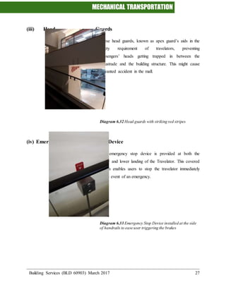
  • 28. MECHANICAL TRANSPORTATION Building Services (BLD 60903) March 2017 27 (iii) Head Guards These head guards, known as apex guard’s aids in the safety requirement of travelators, preventing passengers’ heads getting trapped in between the balustrade and the building structure. This might cause unwanted accident in the mall. Diagram 6.32 Head guards with striking red stripes (iv) Emergency Stop Device The emergency stop device is provided at both the upper and lower landing of the Travelator. This covered button enables users to stop the travelator immediately in the event of an emergency. Diagram 6.33 Emergency Stop Device installed at the side of handrails to ease user triggering the brakes