SlideShare a Scribd company logo
Dec 08
In Circuit Programming method (ICP) Introduction
              g      g        ( )
 Benefit of the highest update flexibility for development, debugging,
   production and repairing by using our In Circuit Programming
   method allowing to reduce your time to market.

 Features: update your SPI Flash soldered on your application board
   by using our dedicated programmers: SF100 and SF300. When
   connected to the application board, the programmer can control
   the
   th SPI b t read or update the Serial Flash content.
           bus to   d       d t th S i l Fl h       t t
In Circuit Programming method (ICP) benefits
In Circuit Programming method (ICP) benefits

Benefits:
       The highest performances (SPI Flash dedicated Programmer)
      - 8Mb = 10sec for update
      - 16Mb = 20sec for update
      The highest code update flexibility for code development, debugging
   warehouse update or repairing (any where at any time)
      The easiest update method for final users
      Reliable (no contact problem due to socket or soldering)
      Ensure th b t SPI signals quality versus th socket solution (l
      E       the best      i   l      lit        the    k t l ti (less
   bus capacitance)
      Time saving (no need to manipulate the memory or unsold for update)
   for the best time to market
Benefits of the highest update flexibility
Benefits of the highest update flexibility

Update flexibility is a must:
       For Reference Board: convenient for your customers trials
      For software development: ensure new code trials in the shortest time
      For Code debugging: easy access and editing of the memory content
   at any time
      For P d ti
      F Production: Program the code after soldering or at th l t ti
                       P         th     d ft       ld i      t the last time f
                                                                             for
   customization before shipment
      For update: in warehouse before shipping in case of new code version
      For repairing: easy field repairing in case of code bug or corruption
      ..
ICP versus IAP and ISP
      IAP = In Application Programming (use the application software to update the Flash)
      ISP = In System Programming (Use an external tool to update the Flash through the application controller)
      ICP = In circuit Programming (Use external tool to update directly the Flash on board)


      IAP or ISP                           ICP is optimized and faster than IAP and ISP
Application communication (IAP)
      Or External tool (ISP)
                                IAP and ISP are often limited by:
                                    External low bus interface                                 ICP
                                   Transfer through chipset
                                    Chipset SPI interface
     Bus                          (
                                  (For Die cost reduction, the chipset
                                                           ,      p
                                  SPI buffer is often reduced to few
     (Jtag..)                     bytes 8, 16 and optimized for fast read but                Chipset
                                  not for fast Serial Flash Programming)
          Chipset                                                                           SPI interface

          SPI interface
                                                                       SF100
                                                                      Or SF300
                                                                                                         SPI

         SPI                                   In Circuit Programming is                              Serial
                                               optimized for Serial Flash:
                    Serial                        Optimum frequency
                                                                                                      Flash
                                                  Optimum SPI buffer (256Bytes)
                                                  O ti          b ff (256B t )
                    Flash                         No limitation due to cost reduction   Application
   Application
The SF100 and SF300  ICP programmer
 The In Circuit Programmers take advantage of the Low lines count of the
   SPI bus (4 lines only) to take the control of the memory.

 These programmers have been designed to fit the different applications
    needs and optimized for the Serial flash offering powerful features,
    high performance for the lowest cost.
                                    cost

                                                                                USB For computer
 ICP connector                                                                  communication
 For application                       LCD screen                SF300
                                       to monitor the         USB & SA mode
                   SF100               Stand Alone mode
                   USB mode                                                          LED for
                                                                                     operation status

                                       Power for                                     ICP connector
                                       Stand Alone                                   For application
                                       mode

                                                                                     Start button
LED for                                                                              For Stand Alone
operation status
                    USB For computer
                    communication
                                                     Buzzer         Socket adaptor
ICP connector description
ICP connector description

                                                    Application Board
                                                                                            Application ICP
                            Red wire:               SPI Programmer Header                   Pin Header
                            Vcc                        (Top view)

                                                        1    Vcc     GND     2

                                                        3    CS      CLK     4
                  SF100
                                         ICP Cable
                                                        5   MISO     MOSI    6

                                                        7   Empty    I/O3    8

                  Programmer
                                              Mistake Proof pin
                                                            p


       Pin                Name of signal                                    Description
       1, 2                   Vcc, Gnd               Vcc supplied from the programmer to the Serial Flash

     3, 4, 5, 6    CS1, CLK, MISO, MOSI              SPI signals

         8                      IO3                  Used to reset the Chipset or switch off the Mosfet

         7                Mistake proof pin          Prevent from wrong connection
Solutions 
to implement the ICP method
to implement the ICP method
Case 1: Update the Serial Flash with 
        Application OFF and serial resistors
        A li ti OFF d i l i t

                                      Memory supplied                    Diode to not supply the
                                      By SF100 or SF300                  application with the
                                                                         programmer

           Chipset not
              supplied


potential
Leakage
Currents
to be measured
(threshold on                                  ICP connector
    resistors I=U/R)                                                        Serial
                                                                               Flash

 Conditions:
 - Chipset must be tolerant to 3.3V      SPI Serial resistors (33 or 47 Ohm) to:
     signals on its SPI IO even if           Filter the SPI signals overshoots and undershoots
     not supplied (small leakage             Limit th l k
                                             Li it the leakage current in the chipset d i ICP
                                                                        t i th hi t during
     current in the chipset)                 update
Case 2: Update the Serial Flash with 
      Application OFF and Mosfet
      A li ti OFF d M f t
                                                  Mosfet to not supply the application
                                                     with the programmer Vcc
                                                     - Application ON    MOSFET ON
                                                     - Application OFF    MOSFET OFF

                                   Memory supplied
                                   By programmer
  Chipset not
     supplied


No Leakage
currents


                                         ICP connector
                                                                    Serial
                                                                       Flash

                               Mosfet to isolate the chipset during the ICP update
Conditions:                       with application OFF:
- Work with all the chipsets      - Application ON     MOSFET ON
                                  - Application OFF     MOSFET OFF
Case 3: Update the Serial Flash with Application 
        Case 3: Update the Serial Flash with Application
        ON and SPI Output in High impedance
                                 Chipset reset by programmer IO3              Memory supplied
                                                                                           li d
                                     before starting the SF update            By application only

          Chipset supplied


SPI Outputs in High
Impedance during
reset or any other
modes..
modes

                                                     ICP connector


  Conditions:
  -  Chipset SPI outputs must be in     SPI Serial resistors (33 or 47 Ohm) to:
  -  High Impedance during the ICP      Filter the SPI signals overshoots and undershoots on edges
  -  update (reset or any other
     modes..)
Case 4: Update the Serial Flash with 
      Application ON and Mosfet
      A li ti ON d M f t
                                                                              Memory supplied
                                                                              By application only

              Chipset supplied


SPI outputs isolated by
Mosfet (CS. CLK, MOSI)


                                                         ICP connector

                                                                              Serial
      SPI Input doesn’t need to be
          isolated (MISO)
                                                                                 Flash
                                     SF100 and SF300 IO3 connected to the Mosfet gates.
                                     Mosfet are supplied by the application but switched off by
                                        the IO3 during the ICP update
                                        - No update    MOSFET ON (chipset connected)
                                        - Update    MOSFET OFF (chipset isolated)

   Conditions:
   - Work with all the chipsets
How can I validate the ICP method with my 
chipset and application?
 The direct ICP method will require a minimum of validation. Actually, the 
 Th  di t ICP  th d  ill          i     i i         f  lid ti  A t ll  th  
   programmer is taking control of the SPI bus and Memory power supply 
   so it is mandatory to check if there is no possible conflict with the 
   application controller (SPI master) or with the application Hardware.
   application controller (SPI master) or with the application Hardware

 For this purpose, DediProg has designed “ICP Evaluation tool” to test and 
   validate the different In Circuit Programming methods on your current 
      lid t  th  diff   t I  Ci it P         i   th d                     t 
   application board without any hardware change required.
ICP Evaluation Board connection
ICP Evaluation Board connection
 The ICP evaluation board can be soldered in your current application 
                                              y              pp
   board in place of your Serial Flash. The ICP evaluation board is 
   designed to support all the different hardware circuits needed to 
   validate the ICP.  
ICP Evaluation Board schematic
ICP Evaluation Board schematic
   User can test all the combinations:   Connect IO3 to the Mosfet
   SPI
   S     MOSFET or S i l resistors
           OS         Serial   i            gate or application reset
   Vcc   Mosfet or Diode or shortcut


                                                                    Serial Flash
Connected to the application
   (Serial Flash Footprint) Test points are used to check   Connect SF100
                            The signals with oscilloscope   Or SF300
Programmer extra features
Programmer extra features
  The SF100 and SF300 has been designed to support the
    update of two different Serial Flash soldered on the
    application board with two extra pins on the ICP
    connector. User has just to select the target memory on
    the DediProg Software: Chip1 or Chip2


  The application ICP connector can be saved by using our
    SO test clip to connect the programmer directly on the
    serial Flash package: SO8N, SO8W or SO16


  More information on the SF100, SF300 programmers and
    ICP evaluation kit on: www.DediProg.com
Contact
DediProg Inc
 4F., No.7, Ln. 143, Xinming Rd., Neihu Dist., Taipei City 
 114, Taiwan
Email for technical support: support@dediprog.com
Email for Sale information: sales@dediprog.com
www.DediProg.com

More Related Content

PDF
IGEP BERLIN
PDF
Dip120 121
PDF
Polnet acp data sheet
PDF
Introduction of AMD Virtual Interrupt Controller
PDF
ICEBreaker Presentation: Complex Sweep Plans for Automatic Component Characte...
PDF
PDF
PDF
Phabrix Sx
IGEP BERLIN
Dip120 121
Polnet acp data sheet
Introduction of AMD Virtual Interrupt Controller
ICEBreaker Presentation: Complex Sweep Plans for Automatic Component Characte...
Phabrix Sx

What's hot (6)

PPTX
Execute DB2 applications more efficiently, in less time and with greater flex...
PDF
REICOM PRODUCTS - POSSIBLE SCENARIOS
DOC
work experience in movon
PDF
Apc series product overview may 2012
PPTX
Echo in WebRTC; Why?
PDF
Apple A Series Application Processor(Update)
Execute DB2 applications more efficiently, in less time and with greater flex...
REICOM PRODUCTS - POSSIBLE SCENARIOS
work experience in movon
Apc series product overview may 2012
Echo in WebRTC; Why?
Apple A Series Application Processor(Update)
Ad

Viewers also liked (15)

PDF
Microsoft SharePoint 2013 - A nova forma de colaboração
PPTX
Cada animal con su casa
PPTX
Modern light
PDF
PPT
PDF
A Póvoa de Varzim - Vol. 6 (1916-1917)
PDF
Scjohnson3
PPT
Ind eng-151-ppt
DOCX
Ind eng-054-doc
PPTX
213556
PDF
Pages from Cooling India_Feb 2012-2
PDF
business plan for fashion eCommerce
PDF
Appasaheb Kapase[CV]
PPTX
Our encounter with d8
PPTX
India as an outsourcing destination
Microsoft SharePoint 2013 - A nova forma de colaboração
Cada animal con su casa
Modern light
A Póvoa de Varzim - Vol. 6 (1916-1917)
Scjohnson3
Ind eng-151-ppt
Ind eng-054-doc
213556
Pages from Cooling India_Feb 2012-2
business plan for fashion eCommerce
Appasaheb Kapase[CV]
Our encounter with d8
India as an outsourcing destination
Ad

Similar to Dedi prog in_circuit_programming_presentation_(nwe_add_update) (20)

PDF
Adv. FPGA Motor Control--EBV & Univ. of Koln: Embedded World 2010
PDF
Ip interfaces by faststream technologies
PDF
IGEP COM ELECTRON
PPTX
Arduino uno
PDF
Sip 02
PDF
PDF
Sip 02
PDF
Lecture Presentation 11.pdfLecture Presentation 9.pdf fpga soc
PDF
Nios2 and ip core
DOCX
D-7-17 Interface an 8-bit serial device using SPI- Thecontrol pin is i.docx
PPTX
EC18713 EMBEDDED SYSTEMS LABORATORY, EC18713
PDF
Apple A Series Application Processor
PPT
300 PLC Presentation training presentation
PDF
Introduction to SCSI over FCP for Linux on System z
PDF
Approaches for Power Management Verification of SOC
PPTX
Tutorial1: mbed開發快速上手
DOCX
RENESAS MICROCONTROLLER PROJECTS CHENNAI-RENESAS RX62N-CHENNAI RENESAS
PDF
Asic implementation of i2 c master bus
PPT
Introduction to nanoWatt XLP: PIC18F46J50
PDF
Trends For Innovating Faster
Adv. FPGA Motor Control--EBV & Univ. of Koln: Embedded World 2010
Ip interfaces by faststream technologies
IGEP COM ELECTRON
Arduino uno
Sip 02
Sip 02
Lecture Presentation 11.pdfLecture Presentation 9.pdf fpga soc
Nios2 and ip core
D-7-17 Interface an 8-bit serial device using SPI- Thecontrol pin is i.docx
EC18713 EMBEDDED SYSTEMS LABORATORY, EC18713
Apple A Series Application Processor
300 PLC Presentation training presentation
Introduction to SCSI over FCP for Linux on System z
Approaches for Power Management Verification of SOC
Tutorial1: mbed開發快速上手
RENESAS MICROCONTROLLER PROJECTS CHENNAI-RENESAS RX62N-CHENNAI RENESAS
Asic implementation of i2 c master bus
Introduction to nanoWatt XLP: PIC18F46J50
Trends For Innovating Faster

Dedi prog in_circuit_programming_presentation_(nwe_add_update)

  • 2. In Circuit Programming method (ICP) Introduction g g ( ) Benefit of the highest update flexibility for development, debugging, production and repairing by using our In Circuit Programming method allowing to reduce your time to market. Features: update your SPI Flash soldered on your application board by using our dedicated programmers: SF100 and SF300. When connected to the application board, the programmer can control the th SPI b t read or update the Serial Flash content. bus to d d t th S i l Fl h t t
  • 3. In Circuit Programming method (ICP) benefits In Circuit Programming method (ICP) benefits Benefits: The highest performances (SPI Flash dedicated Programmer) - 8Mb = 10sec for update - 16Mb = 20sec for update The highest code update flexibility for code development, debugging warehouse update or repairing (any where at any time) The easiest update method for final users Reliable (no contact problem due to socket or soldering) Ensure th b t SPI signals quality versus th socket solution (l E the best i l lit the k t l ti (less bus capacitance) Time saving (no need to manipulate the memory or unsold for update) for the best time to market
  • 4. Benefits of the highest update flexibility Benefits of the highest update flexibility Update flexibility is a must: For Reference Board: convenient for your customers trials For software development: ensure new code trials in the shortest time For Code debugging: easy access and editing of the memory content at any time For P d ti F Production: Program the code after soldering or at th l t ti P th d ft ld i t the last time f for customization before shipment For update: in warehouse before shipping in case of new code version For repairing: easy field repairing in case of code bug or corruption ..
  • 5. ICP versus IAP and ISP IAP = In Application Programming (use the application software to update the Flash) ISP = In System Programming (Use an external tool to update the Flash through the application controller) ICP = In circuit Programming (Use external tool to update directly the Flash on board) IAP or ISP ICP is optimized and faster than IAP and ISP Application communication (IAP) Or External tool (ISP) IAP and ISP are often limited by: External low bus interface ICP Transfer through chipset Chipset SPI interface Bus ( (For Die cost reduction, the chipset , p SPI buffer is often reduced to few (Jtag..) bytes 8, 16 and optimized for fast read but Chipset not for fast Serial Flash Programming) Chipset SPI interface SPI interface SF100 Or SF300 SPI SPI In Circuit Programming is Serial optimized for Serial Flash: Serial Optimum frequency Flash Optimum SPI buffer (256Bytes) O ti b ff (256B t ) Flash No limitation due to cost reduction Application Application
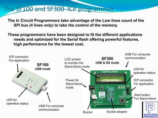
  • 6. The SF100 and SF300  ICP programmer The In Circuit Programmers take advantage of the Low lines count of the SPI bus (4 lines only) to take the control of the memory. These programmers have been designed to fit the different applications needs and optimized for the Serial flash offering powerful features, high performance for the lowest cost. cost USB For computer ICP connector communication For application LCD screen SF300 to monitor the USB & SA mode SF100 Stand Alone mode USB mode LED for operation status Power for ICP connector Stand Alone For application mode Start button LED for For Stand Alone operation status USB For computer communication Buzzer Socket adaptor
  • 7. ICP connector description ICP connector description Application Board Application ICP Red wire: SPI Programmer Header Pin Header Vcc (Top view) 1 Vcc GND 2 3 CS CLK 4 SF100 ICP Cable 5 MISO MOSI 6 7 Empty I/O3 8 Programmer Mistake Proof pin p Pin Name of signal Description 1, 2 Vcc, Gnd Vcc supplied from the programmer to the Serial Flash 3, 4, 5, 6 CS1, CLK, MISO, MOSI SPI signals 8 IO3 Used to reset the Chipset or switch off the Mosfet 7 Mistake proof pin Prevent from wrong connection
  • 9. Case 1: Update the Serial Flash with  Application OFF and serial resistors A li ti OFF d i l i t Memory supplied Diode to not supply the By SF100 or SF300 application with the programmer Chipset not supplied potential Leakage Currents to be measured (threshold on ICP connector resistors I=U/R) Serial Flash Conditions: - Chipset must be tolerant to 3.3V SPI Serial resistors (33 or 47 Ohm) to: signals on its SPI IO even if Filter the SPI signals overshoots and undershoots not supplied (small leakage Limit th l k Li it the leakage current in the chipset d i ICP t i th hi t during current in the chipset) update
  • 10. Case 2: Update the Serial Flash with  Application OFF and Mosfet A li ti OFF d M f t Mosfet to not supply the application with the programmer Vcc - Application ON MOSFET ON - Application OFF MOSFET OFF Memory supplied By programmer Chipset not supplied No Leakage currents ICP connector Serial Flash Mosfet to isolate the chipset during the ICP update Conditions: with application OFF: - Work with all the chipsets - Application ON MOSFET ON - Application OFF MOSFET OFF
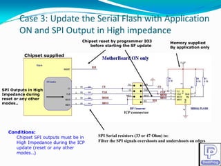
  • 11. Case 3: Update the Serial Flash with Application  Case 3: Update the Serial Flash with Application ON and SPI Output in High impedance Chipset reset by programmer IO3 Memory supplied li d before starting the SF update By application only Chipset supplied SPI Outputs in High Impedance during reset or any other modes.. modes ICP connector Conditions: - Chipset SPI outputs must be in SPI Serial resistors (33 or 47 Ohm) to: - High Impedance during the ICP Filter the SPI signals overshoots and undershoots on edges - update (reset or any other modes..)
  • 12. Case 4: Update the Serial Flash with  Application ON and Mosfet A li ti ON d M f t Memory supplied By application only Chipset supplied SPI outputs isolated by Mosfet (CS. CLK, MOSI) ICP connector Serial SPI Input doesn’t need to be isolated (MISO) Flash SF100 and SF300 IO3 connected to the Mosfet gates. Mosfet are supplied by the application but switched off by the IO3 during the ICP update - No update MOSFET ON (chipset connected) - Update MOSFET OFF (chipset isolated) Conditions: - Work with all the chipsets
  • 13. How can I validate the ICP method with my  chipset and application? The direct ICP method will require a minimum of validation. Actually, the  Th  di t ICP  th d  ill  i     i i   f  lid ti  A t ll  th   programmer is taking control of the SPI bus and Memory power supply  so it is mandatory to check if there is no possible conflict with the  application controller (SPI master) or with the application Hardware. application controller (SPI master) or with the application Hardware For this purpose, DediProg has designed “ICP Evaluation tool” to test and  validate the different In Circuit Programming methods on your current  lid t  th  diff t I  Ci it P i   th d       t  application board without any hardware change required.
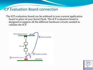
  • 14. ICP Evaluation Board connection ICP Evaluation Board connection The ICP evaluation board can be soldered in your current application  y pp board in place of your Serial Flash. The ICP evaluation board is  designed to support all the different hardware circuits needed to  validate the ICP.  
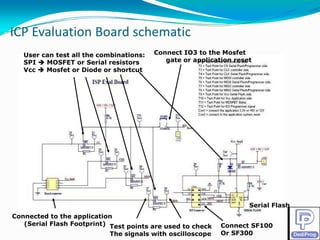
  • 15. ICP Evaluation Board schematic ICP Evaluation Board schematic User can test all the combinations: Connect IO3 to the Mosfet SPI S MOSFET or S i l resistors OS Serial i gate or application reset Vcc Mosfet or Diode or shortcut Serial Flash Connected to the application (Serial Flash Footprint) Test points are used to check Connect SF100 The signals with oscilloscope Or SF300
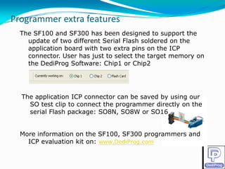
  • 16. Programmer extra features Programmer extra features The SF100 and SF300 has been designed to support the update of two different Serial Flash soldered on the application board with two extra pins on the ICP connector. User has just to select the target memory on the DediProg Software: Chip1 or Chip2 The application ICP connector can be saved by using our SO test clip to connect the programmer directly on the serial Flash package: SO8N, SO8W or SO16 More information on the SF100, SF300 programmers and ICP evaluation kit on: www.DediProg.com
  • 17. Contact DediProg Inc 4F., No.7, Ln. 143, Xinming Rd., Neihu Dist., Taipei City  114, Taiwan Email for technical support: support@dediprog.com Email for Sale information: sales@dediprog.com www.DediProg.com