SlideShare a Scribd company logo
Chapter 3
The Cellular Concept-
Fundamentals of design
School of Information Science
and Engineering, SDU
Outline
l Introduction
l Frequency Reuse
l Channel Assignment Strategies
l Handoff Strategies
l Interference and System Capacity
l Improving Capacity In Cellular Systems
Introduction
l Early mobile radio systems
l A single high powered transmitter (single cell)
l Large coverage area
l Low frequency resource utility
l Low user capacity
l The cellular concept
l A major breakthrough in solving the problem of spectral
congestion and user capacity
l Many low power transmitters (small cells)
l Each cell covers only a small portion of the service area.
l Each base station is allocated a portion of the total number of
channels
l Nearby base stations are assigned different groups of channels
so that the interference between base stations is minimized
Early mobile radio systems
BS
MT
Frequency Reuse
l A service area is split into small geographic areas,
called cells.
l Each cellular base station is allocated a group of
radio channels.
l Base stations in adjacent cells are assigned
different channel groups.
l By limiting the coverage area of a base station, the
same group of channels may be reused by different
cells far away.
l The design process of selecting and allocating
channel groups for all of the cellular base stations
within a system is called frequency reuse or
frequency planning.
Frequency Reuse:
Cell Shapes
l Geometric shapes covering an entire region
without overlap and with equal area.
l By using the hexagon, the fewest number of cells
can cover a geographic region, and the hexagon
closely approximates a circular radiation pattern
which would occur for an omni-directional antenna.
square equilateral triangle hexagon
Frequency Reuse:
Excitation modes
l Center-excited cell
l Base station transmitter is in the center of the cell.
l Omni-directional antennas are used.
l Edge-excited cell
l Base station transmitters are on three of the six
cell vertices.
l Sectored directional antennas are used.
Frequency Reuse:
The concept of Cluster
l Consider a cellular system which has a total of
S duplex channels available for use.
l The S channels are divided among N cells (cluster).
l Each cell is allocated a group of k channels.
l The total number of available radio channels can
be expressed as S=kN.
k
k
k
k
k
k
k
Totally S=kN duplex channels
Cluster: N=7
The N cells which collectively use the
complete set of available frequencies is
called a cluster.
Cluster size: N=4,7,12
Frequency reuse Factor: 1/N
Frequency Reuse:
Reuse Planning
l If a cluster is replicated M times within the
system, the total number of duplex channels,
C, can be given as C = MkN = MS.
l Mathematically, N= i2 + ij + j2
l Where i and j are non-negative integers.
l The nearest co-channel neighbors of a particular
cell can be found by doing what follows:
l move i cells along any chain of hexagons;
l turn 60 degrees counter-clockwise;
l move j cells.
Frequency Reuse:
Reuse Planning
l Examples
A
A
A
A
B
B
B
B
C
C
C
C
G
G
G
G
D
D
D
D
F
F
F
F
E
E
E
E
Cluster
N=7
i=2, j=1
Cluster
Cluster
A
A
A
B
B
B
C
C
C
D
D
D
A
B
C
D
A
B
D
A
B
C
D
CC
B
A
D
Cluster
N=4
i=2, j=0
Cluster
N=4
7-cell reuse 4-cell reuse
19-cell reuse example (N=19)
Figure 3.2 Method of locating co-channel cells in a cellular system. In this example, N = 19 (i.e., I = 3, j = 2).
(Adapted from [Oet83] © IEEE.)
Channel Assignment Strategies
l Objectives:
l Increasing capacity
l Minimizing interference
l Classification:
l Fixed channel assignment strategies
l Dynamic channel assignment strategies
Fixed channel assignment
l Each cell is allocated a predetermined set of
channels.
l Any call attempt within the cell can only be
served by the unused channels in that
particular cell.
l If all the channels in that cell are occupied,
the call is blocked and the subscriber does
not receive service.
Dynamic channel assignment
strategies
l Channels are not allocated to different cells
permanently.
l Each time a call request is made, the serving base
station requests a channel from the MSC.
l The switch then allocates a channel to the
requested cell following an algorithm that takes into
account:
l the likelihood of fixture blocking within the cell
l the frequency of use of the candidate channel
l the reuse distance of the channel
l other cost functions.
Handoff Strategies
l Handoff:
l When a mobile moves into a different cell while a
conversation is in progress, the MSC
automatically transfers the call to a new channel
belonging to the new base station.
l Processing handoffs is an important task in
any cellular radio system.
Handoff Strategies:
Requirements
l Handoffs must be performed:
l Successfully;
l As infrequently as possible;
l Imperceptible to the users.
l How to meet these requirements?
l Specify an optimum signal level to initiate a handoff;
l Decide optimally when to handoff;
l Consider the statistics of dwell time.
20121213092949132(1)
Handoff Strategies:
Signal strength measurements
l First generation analog cellular systems:
l Signal strength measurements are made by the
base stations and supervised by the MSC.
l Second generation systems:
l Handoff decisions are mobile assisted;
l The MSC no longer constantly monitors signal
strengths.
Handoff Strategies:
Managing of handoffs
l Prioritizing Handoffs
l Guard channel: a fraction of the total available channels in
a cell is reserved exclusively for handoff requests from
ongoing calls which may be handed off into the cell.
l Queuing of handoff requests: to decrease the probability of
forced termination of a call due to lack of available
channels.
l Queuing of handoffs is possible due to the fact that there is
a finite time interval between the time the received signal
level drops below the handoff threshold and the time the
call is terminated due to insufficient signal level.
Practical Handoff Considerations
l Observations
l High speed vehicles pass through the coverage region of a cell within a
matter of seconds.
l Pedestrian users may never need a handoff during a call.
l Particularly with the addition of microcells to provide capacity, the MSC can
quickly become burdened if high speed users are constantly being passed
between very small cells.
l It is difficult for cellular service providers to obtain new physical cell site
locations in urban areas.
l Another practical handoff problem in microcell systems is known as cell
dragging.
l Solutions
l The umbrella cell approach.
l Newer cellular systems make handoff decisions based on a wide range of
metrics other than signal strength.
l Soft handoff (CDMA cellular networks): The ability to select between the
instantaneous received signals from a variety of base stations is called soft
handoff.
The umbrella cell approach
Interference and System
Capacity
l Interference is the major limiting factor in the
performance of cellular radio systems:
l a major bottleneck in increasing capacity
l often responsible for dropped calls
l The two major types of system-generated
cellular interference are:
l co-channel interference
l adjacent channel interference
l Power Control for Reducing Interference
Co-channel Interference and
System Capacity
l Co-channel Interference
l Cells using the same set of frequencies are called co-
channel cells, and the interference between signals from
these cells is called co-channel interference.
l Unlike thermal noise which can be overcome by increasing
the signal-to-noise ration (SNR), co-channel interference
cannot be combated by simply increasing the carrier power
of a transmitter. This is because an increase in carrier
transmit power increases the interference to neighboring
co-channel cells.
l To reduce co-channel interference, co-channel cells must
be physically separated by a minimum distance to provide
sufficient isolation due to propagation.
Co-channel cells for 7-cell
reuse
Co-channel Interference and
System Capacity
l The co-channel interference ratio is a
function of the radius of the cell (B) and the
distance between centers of the nearest co-
channel cells (D).
l By increasing the ratio of D/R, the spatial
separation between co-channel cells relative
to the coverage distance of a cell is increased.
Thus interference is reduced.
Cochannel reuse ratio
l The parameter Q= D/R, called the cochannel reuse
ratio, is related to the cluster size N.
l When the size of each cell is approximately the same, and
the base stations transmit the same power, we have
Q= D/R=(3N)1/3
l A small value of Q provides larger capacity since the
cluster size N is small, whereas a large value of Q
improves the transmission quality, due to a smaller level of
co-channel interference.
l A trade-off must be made between these two objectives in
actual cellular design.
Smaller N is greater capacity
Signal-to-interference ratio
(SIR)
l The signal-to-interference ratio (SIR) for a mobile
receiver can be expressed as
l S denotes the desired signal power;
l Ii is the interference power caused by the i-th interfering
co-channel cell base station;
l i0 is the number of cochannel interfering cells.
0
0
i
i
i
S
SIR
I
=
=
∑
Signal-to-interference ratio
(SIR)
Signal-to-interference ratio
(SIR)
l The average received power
P at a distance d from the
transmitting antenna is
approximated by
l If all base stations transmit
at the same power level, the
SIR can be given as
l In practice, measures
should be taken to keep the
SIR on a acceptable level.
0
0
n
r
d
P P
d
 
=  
 
0
0
n
i
n
i
i
R
SIR
D
−
−
=
=
∑
Adjacent Channel Interference
l Interference resulting from signals which are
adjacent in frequency to the desired signal is
called adjacent channel interference.
l Adjacent channel interference results from
imperfect receiver filters which allow nearby
frequencies to leak into the passband.
l Near-far effect:
l If an adjacent channel user is transmitting in very
close range to a subscriber's receiver, the problem
can be particularly serious.
Adjacent Channel Interference
l Adjacent channel interference can be minimized
through careful filtering and channel assignments:
l By keeping the frequency separation between each
channel in a given cell as large as possible, the adjacent
channel interference may be reduced considerably.
l Channel allocation schemes can also prevent a secondary
source of adjacent channel interference by avoiding the
use of adjacent channels in neighboring cell sites.
l High Q cavity filters can be used in order to reject adjacent
channel interference.
20121213092949132(1)
Power Control for Reducing
Interference
l In practical cellular radio and personal communication systems
the power levels transmitted by every subscriber unit are under
constant control by the serving base stations.
l This is done to ensure that each mobile transmits the smallest
power necessary to maintain a good quality link on the reverse
channel.
l Power control not only helps prolong battery life for the
subscriber unit, but also dramatically improves the reverse
channel S/I in the system.
l Power control is especially important for emerging CDMA spread
spectrum systems that allow every user in every cell to share the
same radio channel.
Improving Capacity In Cellular
Systems
l As the demand for wireless service increases, the
number of channels assigned to a cell eventually
becomes insufficient to support the required number
of users.
l Techniques to expand the capacity of cellular
systems :
l Cell splitting: increases the number of base stations in
order to increase capacity.
l Sectoring: relies on base station antenna placements to
improve capacity by reducing co-channel interference.
l Coverage zone: distributes the coverage of a cell and
extends the cell boundary to hard-to-reach places.
Cell Splitting
l Cell splitting is the process of subdividing a
congested cell into smaller cells, each with its
own base station and a corresponding
reduction in antenna height and transmitter
power.
l Cell splitting increases the capacity of a
cellular system since it increases the number
of times that channels are reused.
Cells are split to add channels
with no new spectrum usage
Cell Splitting increases capacity
Sectoring
l The technique for decreasing co-channel
interference and thus increasing system
capacity by using directional antennas is
called sectoring.
l The factor by which the co-channel
interference is reduced depends on the
amount of sectoring used.
Sectoring improves S/I
A Novel Microcell Zone Concept
l Zone Concept
l Zone sites are connected to a single base station and share the
same radio equipment.
l The zones are connected by coaxial cable, fiberoptic cable, or
microwave link to the base station.
l Multiple zones and a single base station make up a cell.
l As a mobile travels within the cell, it is served by the zone with
the strongest signal.
l This technique is particularly useful along highways or along
urban traffic corridors.
l This approach is superior to sectoring since antennas are placed
at the outer edges of the cell, and any base station channel may
be assigned to any zone by the base station.
l In comparison with sectoring, the number of handoffs can be
reduced significantly.
The Zone Cell Concept

More Related Content

PPT
Cellular concept
PPTX
Final wc
PPT
Mobile Comm- Garima Maam
PPT
Thr cellular concept
PPTX
Cellular Concept
PDF
Cellular concepts
PPT
fundamenatals of cellular enginering
PPSX
Concepts of & cell sectoring and micro cell
Cellular concept
Final wc
Mobile Comm- Garima Maam
Thr cellular concept
Cellular Concept
Cellular concepts
fundamenatals of cellular enginering
Concepts of & cell sectoring and micro cell

What's hot (20)

PPTX
Cellular concept in mobile communication
PPTX
Cellular concepts
PPT
Lec 3 and 4 cellular concept 1
PPSX
ELEMENTS OF CELLULAR RADIO SYSTEM DESIGN
PDF
Fundamentals of Cellular Communications
PPT
The cellular concept
PDF
Cellular Architecture Design Concepts
PPTX
Presentation on cellular concept
PDF
Wireless traffic theory and handoff
PPT
wireless-communication-architecture
DOCX
introduction to channel borrowing scheme in cellular networks
PPTX
Cellular concepts
PPT
cell splitting and sectoring
DOCX
Cmc handbook
PPTX
Cellular concepts
PPT
Interferences
PPT
Mobile communication concepts
PPTX
Chapter 5(Cellular Concepts)
PDF
Wt module 2
Cellular concept in mobile communication
Cellular concepts
Lec 3 and 4 cellular concept 1
ELEMENTS OF CELLULAR RADIO SYSTEM DESIGN
Fundamentals of Cellular Communications
The cellular concept
Cellular Architecture Design Concepts
Presentation on cellular concept
Wireless traffic theory and handoff
wireless-communication-architecture
introduction to channel borrowing scheme in cellular networks
Cellular concepts
cell splitting and sectoring
Cmc handbook
Cellular concepts
Interferences
Mobile communication concepts
Chapter 5(Cellular Concepts)
Wt module 2
Ad

Similar to 20121213092949132(1) (20)

PDF
cHAPTER 1.pdf
PPT
fdocuments.net_1-cellular-system-design-fundamentals-chapter-3-wireless-commu...
PPT
WC PPT UNIT-II.ppt
PPT
Freq reuse detail.ppt
PPTX
Wireless and mobile Communication Networks.pptx
PPTX
cellular ppt
PPTX
WEEK3 TE303, Telecommunication networks. TE. Channel Assignments
PPTX
wireless communication chapterr 2 part 1
PDF
Wireless network planning and operation
PDF
Comnicacines inalambricas: el Concepto celular: diseño y calculos
PDF
Lec 2 Cell Planning Principles lecture notes
PPT
Chapter 2 Cellular Systems--Cellular Concepts.ppt
PPT
cellular-communications
PDF
Wireless communication networks
PDF
Wireless Communication Networks (1).pdf
PPT
Cellular concepts and system design fundamentals
PPTX
cellular concepts in wireless communication
PPTX
PDF
Mobile Communication
PDF
03. Chapter- Three Elements of Cellular Radio System Design1.pdf
cHAPTER 1.pdf
fdocuments.net_1-cellular-system-design-fundamentals-chapter-3-wireless-commu...
WC PPT UNIT-II.ppt
Freq reuse detail.ppt
Wireless and mobile Communication Networks.pptx
cellular ppt
WEEK3 TE303, Telecommunication networks. TE. Channel Assignments
wireless communication chapterr 2 part 1
Wireless network planning and operation
Comnicacines inalambricas: el Concepto celular: diseño y calculos
Lec 2 Cell Planning Principles lecture notes
Chapter 2 Cellular Systems--Cellular Concepts.ppt
cellular-communications
Wireless communication networks
Wireless Communication Networks (1).pdf
Cellular concepts and system design fundamentals
cellular concepts in wireless communication
Mobile Communication
03. Chapter- Three Elements of Cellular Radio System Design1.pdf
Ad

Recently uploaded (20)

PDF
Soil Improvement Techniques Note - Rabbi
PDF
Analyzing Impact of Pakistan Economic Corridor on Import and Export in Pakist...
PDF
Unit I ESSENTIAL OF DIGITAL MARKETING.pdf
PDF
737-MAX_SRG.pdf student reference guides
PDF
Visual Aids for Exploratory Data Analysis.pdf
PDF
A SYSTEMATIC REVIEW OF APPLICATIONS IN FRAUD DETECTION
PDF
Exploratory_Data_Analysis_Fundamentals.pdf
PPTX
Current and future trends in Computer Vision.pptx
PPTX
6ME3A-Unit-II-Sensors and Actuators_Handouts.pptx
PPT
Occupational Health and Safety Management System
PDF
III.4.1.2_The_Space_Environment.p pdffdf
PDF
R24 SURVEYING LAB MANUAL for civil enggi
PPTX
Artificial Intelligence
PPTX
Safety Seminar civil to be ensured for safe working.
PPT
Introduction, IoT Design Methodology, Case Study on IoT System for Weather Mo...
PPTX
communication and presentation skills 01
PPT
INTRODUCTION -Data Warehousing and Mining-M.Tech- VTU.ppt
PPTX
Fundamentals of safety and accident prevention -final (1).pptx
PDF
null (2) bgfbg bfgb bfgb fbfg bfbgf b.pdf
PPTX
UNIT 4 Total Quality Management .pptx
Soil Improvement Techniques Note - Rabbi
Analyzing Impact of Pakistan Economic Corridor on Import and Export in Pakist...
Unit I ESSENTIAL OF DIGITAL MARKETING.pdf
737-MAX_SRG.pdf student reference guides
Visual Aids for Exploratory Data Analysis.pdf
A SYSTEMATIC REVIEW OF APPLICATIONS IN FRAUD DETECTION
Exploratory_Data_Analysis_Fundamentals.pdf
Current and future trends in Computer Vision.pptx
6ME3A-Unit-II-Sensors and Actuators_Handouts.pptx
Occupational Health and Safety Management System
III.4.1.2_The_Space_Environment.p pdffdf
R24 SURVEYING LAB MANUAL for civil enggi
Artificial Intelligence
Safety Seminar civil to be ensured for safe working.
Introduction, IoT Design Methodology, Case Study on IoT System for Weather Mo...
communication and presentation skills 01
INTRODUCTION -Data Warehousing and Mining-M.Tech- VTU.ppt
Fundamentals of safety and accident prevention -final (1).pptx
null (2) bgfbg bfgb bfgb fbfg bfbgf b.pdf
UNIT 4 Total Quality Management .pptx

20121213092949132(1)

  • 1. Chapter 3 The Cellular Concept- Fundamentals of design School of Information Science and Engineering, SDU
  • 2. Outline l Introduction l Frequency Reuse l Channel Assignment Strategies l Handoff Strategies l Interference and System Capacity l Improving Capacity In Cellular Systems
  • 3. Introduction l Early mobile radio systems l A single high powered transmitter (single cell) l Large coverage area l Low frequency resource utility l Low user capacity l The cellular concept l A major breakthrough in solving the problem of spectral congestion and user capacity l Many low power transmitters (small cells) l Each cell covers only a small portion of the service area. l Each base station is allocated a portion of the total number of channels l Nearby base stations are assigned different groups of channels so that the interference between base stations is minimized
  • 4. Early mobile radio systems BS MT
  • 5. Frequency Reuse l A service area is split into small geographic areas, called cells. l Each cellular base station is allocated a group of radio channels. l Base stations in adjacent cells are assigned different channel groups. l By limiting the coverage area of a base station, the same group of channels may be reused by different cells far away. l The design process of selecting and allocating channel groups for all of the cellular base stations within a system is called frequency reuse or frequency planning.
  • 6. Frequency Reuse: Cell Shapes l Geometric shapes covering an entire region without overlap and with equal area. l By using the hexagon, the fewest number of cells can cover a geographic region, and the hexagon closely approximates a circular radiation pattern which would occur for an omni-directional antenna. square equilateral triangle hexagon
  • 7. Frequency Reuse: Excitation modes l Center-excited cell l Base station transmitter is in the center of the cell. l Omni-directional antennas are used. l Edge-excited cell l Base station transmitters are on three of the six cell vertices. l Sectored directional antennas are used.
  • 8. Frequency Reuse: The concept of Cluster l Consider a cellular system which has a total of S duplex channels available for use. l The S channels are divided among N cells (cluster). l Each cell is allocated a group of k channels. l The total number of available radio channels can be expressed as S=kN. k k k k k k k Totally S=kN duplex channels Cluster: N=7 The N cells which collectively use the complete set of available frequencies is called a cluster. Cluster size: N=4,7,12 Frequency reuse Factor: 1/N
  • 9. Frequency Reuse: Reuse Planning l If a cluster is replicated M times within the system, the total number of duplex channels, C, can be given as C = MkN = MS. l Mathematically, N= i2 + ij + j2 l Where i and j are non-negative integers. l The nearest co-channel neighbors of a particular cell can be found by doing what follows: l move i cells along any chain of hexagons; l turn 60 degrees counter-clockwise; l move j cells.
  • 10. Frequency Reuse: Reuse Planning l Examples A A A A B B B B C C C C G G G G D D D D F F F F E E E E Cluster N=7 i=2, j=1 Cluster Cluster A A A B B B C C C D D D A B C D A B D A B C D CC B A D Cluster N=4 i=2, j=0 Cluster N=4 7-cell reuse 4-cell reuse
  • 11. 19-cell reuse example (N=19) Figure 3.2 Method of locating co-channel cells in a cellular system. In this example, N = 19 (i.e., I = 3, j = 2). (Adapted from [Oet83] © IEEE.)
  • 12. Channel Assignment Strategies l Objectives: l Increasing capacity l Minimizing interference l Classification: l Fixed channel assignment strategies l Dynamic channel assignment strategies
  • 13. Fixed channel assignment l Each cell is allocated a predetermined set of channels. l Any call attempt within the cell can only be served by the unused channels in that particular cell. l If all the channels in that cell are occupied, the call is blocked and the subscriber does not receive service.
  • 14. Dynamic channel assignment strategies l Channels are not allocated to different cells permanently. l Each time a call request is made, the serving base station requests a channel from the MSC. l The switch then allocates a channel to the requested cell following an algorithm that takes into account: l the likelihood of fixture blocking within the cell l the frequency of use of the candidate channel l the reuse distance of the channel l other cost functions.
  • 15. Handoff Strategies l Handoff: l When a mobile moves into a different cell while a conversation is in progress, the MSC automatically transfers the call to a new channel belonging to the new base station. l Processing handoffs is an important task in any cellular radio system.
  • 16. Handoff Strategies: Requirements l Handoffs must be performed: l Successfully; l As infrequently as possible; l Imperceptible to the users. l How to meet these requirements? l Specify an optimum signal level to initiate a handoff; l Decide optimally when to handoff; l Consider the statistics of dwell time.
  • 18. Handoff Strategies: Signal strength measurements l First generation analog cellular systems: l Signal strength measurements are made by the base stations and supervised by the MSC. l Second generation systems: l Handoff decisions are mobile assisted; l The MSC no longer constantly monitors signal strengths.
  • 19. Handoff Strategies: Managing of handoffs l Prioritizing Handoffs l Guard channel: a fraction of the total available channels in a cell is reserved exclusively for handoff requests from ongoing calls which may be handed off into the cell. l Queuing of handoff requests: to decrease the probability of forced termination of a call due to lack of available channels. l Queuing of handoffs is possible due to the fact that there is a finite time interval between the time the received signal level drops below the handoff threshold and the time the call is terminated due to insufficient signal level.
  • 20. Practical Handoff Considerations l Observations l High speed vehicles pass through the coverage region of a cell within a matter of seconds. l Pedestrian users may never need a handoff during a call. l Particularly with the addition of microcells to provide capacity, the MSC can quickly become burdened if high speed users are constantly being passed between very small cells. l It is difficult for cellular service providers to obtain new physical cell site locations in urban areas. l Another practical handoff problem in microcell systems is known as cell dragging. l Solutions l The umbrella cell approach. l Newer cellular systems make handoff decisions based on a wide range of metrics other than signal strength. l Soft handoff (CDMA cellular networks): The ability to select between the instantaneous received signals from a variety of base stations is called soft handoff.
  • 21. The umbrella cell approach
  • 22. Interference and System Capacity l Interference is the major limiting factor in the performance of cellular radio systems: l a major bottleneck in increasing capacity l often responsible for dropped calls l The two major types of system-generated cellular interference are: l co-channel interference l adjacent channel interference l Power Control for Reducing Interference
  • 23. Co-channel Interference and System Capacity l Co-channel Interference l Cells using the same set of frequencies are called co- channel cells, and the interference between signals from these cells is called co-channel interference. l Unlike thermal noise which can be overcome by increasing the signal-to-noise ration (SNR), co-channel interference cannot be combated by simply increasing the carrier power of a transmitter. This is because an increase in carrier transmit power increases the interference to neighboring co-channel cells. l To reduce co-channel interference, co-channel cells must be physically separated by a minimum distance to provide sufficient isolation due to propagation.
  • 24. Co-channel cells for 7-cell reuse
  • 25. Co-channel Interference and System Capacity l The co-channel interference ratio is a function of the radius of the cell (B) and the distance between centers of the nearest co- channel cells (D). l By increasing the ratio of D/R, the spatial separation between co-channel cells relative to the coverage distance of a cell is increased. Thus interference is reduced.
  • 26. Cochannel reuse ratio l The parameter Q= D/R, called the cochannel reuse ratio, is related to the cluster size N. l When the size of each cell is approximately the same, and the base stations transmit the same power, we have Q= D/R=(3N)1/3 l A small value of Q provides larger capacity since the cluster size N is small, whereas a large value of Q improves the transmission quality, due to a smaller level of co-channel interference. l A trade-off must be made between these two objectives in actual cellular design.
  • 27. Smaller N is greater capacity
  • 28. Signal-to-interference ratio (SIR) l The signal-to-interference ratio (SIR) for a mobile receiver can be expressed as l S denotes the desired signal power; l Ii is the interference power caused by the i-th interfering co-channel cell base station; l i0 is the number of cochannel interfering cells. 0 0 i i i S SIR I = = ∑
  • 30. Signal-to-interference ratio (SIR) l The average received power P at a distance d from the transmitting antenna is approximated by l If all base stations transmit at the same power level, the SIR can be given as l In practice, measures should be taken to keep the SIR on a acceptable level. 0 0 n r d P P d   =     0 0 n i n i i R SIR D − − = = ∑
  • 31. Adjacent Channel Interference l Interference resulting from signals which are adjacent in frequency to the desired signal is called adjacent channel interference. l Adjacent channel interference results from imperfect receiver filters which allow nearby frequencies to leak into the passband. l Near-far effect: l If an adjacent channel user is transmitting in very close range to a subscriber's receiver, the problem can be particularly serious.
  • 32. Adjacent Channel Interference l Adjacent channel interference can be minimized through careful filtering and channel assignments: l By keeping the frequency separation between each channel in a given cell as large as possible, the adjacent channel interference may be reduced considerably. l Channel allocation schemes can also prevent a secondary source of adjacent channel interference by avoiding the use of adjacent channels in neighboring cell sites. l High Q cavity filters can be used in order to reject adjacent channel interference.
  • 34. Power Control for Reducing Interference l In practical cellular radio and personal communication systems the power levels transmitted by every subscriber unit are under constant control by the serving base stations. l This is done to ensure that each mobile transmits the smallest power necessary to maintain a good quality link on the reverse channel. l Power control not only helps prolong battery life for the subscriber unit, but also dramatically improves the reverse channel S/I in the system. l Power control is especially important for emerging CDMA spread spectrum systems that allow every user in every cell to share the same radio channel.
  • 35. Improving Capacity In Cellular Systems l As the demand for wireless service increases, the number of channels assigned to a cell eventually becomes insufficient to support the required number of users. l Techniques to expand the capacity of cellular systems : l Cell splitting: increases the number of base stations in order to increase capacity. l Sectoring: relies on base station antenna placements to improve capacity by reducing co-channel interference. l Coverage zone: distributes the coverage of a cell and extends the cell boundary to hard-to-reach places.
  • 36. Cell Splitting l Cell splitting is the process of subdividing a congested cell into smaller cells, each with its own base station and a corresponding reduction in antenna height and transmitter power. l Cell splitting increases the capacity of a cellular system since it increases the number of times that channels are reused.
  • 37. Cells are split to add channels with no new spectrum usage
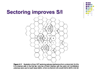
  • 39. Sectoring l The technique for decreasing co-channel interference and thus increasing system capacity by using directional antennas is called sectoring. l The factor by which the co-channel interference is reduced depends on the amount of sectoring used.
  • 42. A Novel Microcell Zone Concept l Zone Concept l Zone sites are connected to a single base station and share the same radio equipment. l The zones are connected by coaxial cable, fiberoptic cable, or microwave link to the base station. l Multiple zones and a single base station make up a cell. l As a mobile travels within the cell, it is served by the zone with the strongest signal. l This technique is particularly useful along highways or along urban traffic corridors. l This approach is superior to sectoring since antennas are placed at the outer edges of the cell, and any base station channel may be assigned to any zone by the base station. l In comparison with sectoring, the number of handoffs can be reduced significantly.
  • 43. The Zone Cell Concept