


![PIN-1
PC6 (RESET)
Pin6 of PORTC
Pin by default is used as RESET pin. PC6 can only be used as I/O pin
when RSTDISBL Fuse is programmed.
PIN-2
PD0 (RXD)
Pin0 of PORTD
RXD (Data Input Pin for USART)
USART Serial Communication Interface
[Can be used for programming]
PIN-3
PD1 (TXD)
Pin1 of PORTD
TXD (Data Output Pin for USART)
USART Serial Communication Interface
[Can be used for programming]
INT2( External Interrupt 2 Input)](https://image.slidesharecdn.com/introductiontoarduinopptmain-210323135526/85/Introduction-to-arduino-ppt-main-25-320.jpg)


![ PIN-15
PB1 (OC1A)
Pin1 of PORTB
OC1A (Timer/Counter1 Output Compare Match A Output)
PIN-16
PB2 (SS/OC1B)
Pin2 of PORTB
SS (SPI Slave Select Input). This pin is low when controller acts
as slave.
[Serial Peripheral Interface (SPI) for programming]
OC1B (Timer/Counter1 Output Compare Match B Output)
PIN-17
PB3 (MOSI/OC2A)
Pin3 of PORTB
MOSI (Master Output Slave Input). When controller acts as
slave, the data is received by this pin. [Serial Peripheral Interface
(SPI) for programming]
OC2 (Timer/Counter2 Output Compare Match Output)](https://image.slidesharecdn.com/introductiontoarduinopptmain-210323135526/85/Introduction-to-arduino-ppt-main-29-320.jpg)
![PIN-18
PB4 (MISO)
Pin4 of PORTB
MISO (Master Input Slave Output). When controller acts as
slave, the data is sent to master by this controller through this
pin.
[Serial Peripheral Interface (SPI) for programming]
PIN-19
PB5 (SCK)
Pin5 of PORTB
SCK (SPI Bus Serial Clock). This is the clock shared between this
controller and other system for accurate data transfer.
[Serial Peripheral Interface (SPI) for programming]
PIN-20
AVCC
Power for Internal ADC Converter](https://image.slidesharecdn.com/introductiontoarduinopptmain-210323135526/85/Introduction-to-arduino-ppt-main-30-320.jpg)


Introduction to arduino ppt main
- 2. OVERVIEW Arduino is a open-source based on an easy-to-use hardware and software. It consists of a circuit board, which can be programed (referred to as a microcontroller) and a ready-made software called Arduino IDE (Integrated Development Environment), which is used to write and upload the computer code to the physical board. This board contains a microcontroller which is able to be programmed to sense and control objects in the physical world. By responding to sensors and inputs, the Arduino is able to interact with a large array of outputs such as LEDs, motors and displays. Because of it’s flexibility and low cost, Arduino has become a very popular choice for makers and makerspaces looking to create interactive hardware projects.
- 3. Features: Arduino boards are able to read analog or digital input signals from different sensors and turn it into an output such as activating a motor, turning LED on/off, connect to the cloud and many other actions. You can control your board functions by sending a set of instructions to the microcontroller on the board via Arduino IDE (referred to as uploading software). Unlike most previous programmable circuit boards, Arduino does not need an extra piece of hardware (called a programmer) in order to load a new code onto the board. You can simply use a USB cable. Additionally, the Arduino IDE uses a simplified version of C++, making it easier to learn to program. Finally, Arduino provides a standard form factor that breaks the functions of the micro-controller into a more accessible package.
- 4. What is Arduino in IoT? Arduino acts as the brain of the system and processes the data from the sensor. Arduino is an open source hardware platform that is readily available for engineers across the globe to build projects. It comes with an ATMEGA microcontroller that processes the data and facilitates the proper working of the IoT system. And the beauty is that the Arduino can be programmed ‘n’ number of times making it possible for you to build various types of IoT projects just by changing a simple code. You need to use C++ language for Arduino programming. Also IDE software is needed for Arduino based IoT projects. And you need to use ESP-8266 WiFi module to establish the WiFi communication between the Arduino and cloud platform.
- 5. TYPES OF ARDUINO BORADS Arduino Uno (R3) The Uno is a huge option for your initial Arduino. This Arduino board depends on an ATmega328P based microcontroller. As compared with other types of arduino boards, it is very simple to use like the Arduino Mega type board. It consists of 14-digital I/O pins, where 6- pins can be used as PWM(pulse width modulation outputs), 6-analog inputs, a reset button, a power jack, a USB connection, an In-Circuit Serial Programming header (ICSP), etc. It includes everything required to hold up the microcontroller; simply attach it to a PC with the help of a USB cable and give the supply to get started with an AC- to-DC adapter or battery. Arduino Uno is the most frequently used board and it is the standard form apart from all the existing Arduino Boards
- 6. Arduino Nano This is a small board based on the microcontrollers like ATmega328P otherwise ATmega628 but the connection of this board is the same as to the Arduino UNO board. This kind of microcontroller board is very small in size, sustainable, flexible, and reliable. As compared with the Arduino Uno board, it is small in size. The devices like mini USB and Arduino IDE are necessary to build the projects. This board mainly includes analog pins-8, digital pins-14 with the set of an I/O pin, power pins-6 & RST (reset) pins-2.
- 7. Arduino Due This Arduino board depends on the ARM Cortex-M3 and it is the first Arduino microcontroller board. This board includes digital I/O pins-54 where 12-pins are PWM o/p pins, analog pins -12, UARTs-4, a CLK with 84 MHz, an USB OTG, DAC-2, a power jack, TWI-2, a JTAG header, an SPI header, two buttons for reset & erase. This board works with 3.3V where the highest voltage that the pins of input/output can stand is 3.3V because providing a high voltage to any I/O pin can lead to damage the board. This board is simply connected to a computer through a small USB cable otherwise it can be powered through an AC to DC adapter. This Arduino Due board is suitable with all shields of Arduino at 3.3V.
- 8. Arduino Mega (R3) Board The Arduino Mega is similar to the UNO’s big brother. It includes lots of digital I/O pins (from that, 14- pins can be used as PWM o/ps), 6- analog inputs, a reset button, a power jack, a USB connection, and a reset button. It includes everything required to hold up the microcontroller; simply attach it to a PC with the help of a USB cable and give the supply to get started with an AC-to-DC adapter or battery. The huge number of pins make this Arduino board very helpful for designing projects that need a bunch of digital i/ps or o/ps like lots of buttons.
- 9. Arduino Leonardo Board The first development board of an Arduino is the Leonardo board. This board uses one microcontroller along with the USB. That means, it can be very simple and cheap also. Because this board handles USB directly, program libraries are obtainable which let the Arduino board to follow a keyboard of the computer, mouse, etc.
- 10. Comparison Arduino Board Processor Memory Digital I/O Analogue I/O Arduino Uno 16Mhz ATmega328 2KB SRAM, 32KB flash 14 6 input, 0 output Arduino Due 84MHz AT91SAM3X 8E 96KB SRAM, 512KB flash 54 12 input, 2 output Arduino Mega 16MHz ATmega2560 8KB SRAM, 256KB flash 54 16 input, 0 output Arduino Leonard 16MHz ATmega32u 4 2.5KB SRAM, 32KB flash 20 12 input, 0 output
- 11. Arduino uno - Board Description
- 12. Pin 1 - Power USB Arduino board can be powered by using the USB cable from your computer. All you need to do is connect the USB cable to the USB connection (1). Pin -2- Power (Barrel Jack) Arduino boards can be powered directly from the AC mains power supply by connecting it to the Barrel Jack (2). PIN -3- Voltage Regulator The function of the voltage regulator is to control the voltage given to the Arduino board and stabilize the DC voltages used by the processor and other elements. PIN-4-Crystal Oscillator The crystal oscillator helps Arduino in dealing with time issues. How does Arduino calculate time? The answer is, by using the crystal oscillator. The number printed on top of the Arduino crystal is 16.000H9H. It tells us that the frequency is 16,000,000 Hertz or 16 MHz.
- 13. PIN- 5,17- Arduino Reset You can reset your Arduino board, i.e., start your program from the beginning. You can reset the UNO board in two ways. First, by using the reset button (17) on the board. Second, you can connect an external reset button to the Arduino pin labelled RESET (5). PIN-6,7,8,9- Pins (3.3, 5, GND, Vin) 3.3V (6) − Supply 3.3 output volt 5V (7) − Supply 5 output volt Most of the components used with Arduino board works fine with 3.3 volt and 5 volt. GND (8)(Ground) − There are several GND pins on the Arduino, any of which can be used to ground your circuit. Vin (9) − This pin also can be used to power the Arduino board from an external power source, like AC mains power supply.
- 14. PIN-10- Analog pins The Arduino UNO board has six analog input pins A0 through A5. These pins can read the signal from an analog sensor like the humidity sensor or temperature sensor and convert it into a digital value that can be read by the microprocessor. PIN- 11-Main microcontroller Each Arduino board has its own microcontroller (11). You can assume it as the brain of your board. The main IC (integrated circuit) on the Arduino is slightly different from board to board. The microcontrollers are usually of the ATMEL Company. You must know what IC your board has before loading up a new program from the Arduino IDE. This information is available on the top of the IC. For more details about the IC construction and functions, you can refer to the data sheet. PIN-12-ICSP pin Mostly, ICSP (12) is an AVR, a tiny programming header for the Arduino consisting of MOSI, MISO, SCK, RESET, VCC, and GND. It is often referred to as an SPI (Serial Peripheral Interface), which could be considered as an "expansion" of the output. Actually, you are slaving the output device to the master of the SPI bus. PIN-13- Power LED indicator This LED should light up when you plug your Arduino into a power source to indicate that your board is powered up correctly. If this light does not turn on, then there is something wrong with the connection.
- 15. PIN-14- TX and RX LEDs On your board, you will find two labels: TX (transmit) and RX (receive). They appear in two places on the Arduino UNO board. First, at the digital pins 0 and 1, to indicate the pins responsible for serial communication. Second, the TX and RX led (13). The TX led flashes with different speed while sending the serial data. The speed of flashing depends on the baud rate used by the board. RX flashes during the receiving process. PIN-15-Digital I/O The Arduino UNO board has 14 digital I/O pins (15) (of which 6 provide PWM (Pulse Width Modulation) output. These pins can be configured to work as input digital pins to read logic values (0 or 1) or as digital output pins to drive different modules like LEDs, relays, etc. The pins labeled “~” can be used to generate PWM. PIN-16- AREF AREF stands for Analog Reference. It is sometimes, used to set an external reference voltage (between 0 and 5 Volts) as the upper limit for the analog input pins.
- 16. ATMega328P Microcontroller The ATmega328/P is a low-power 8-bit microcontroller based on the AVR enhanced RISC (reduced instruction set computer) architecture. It is the most popular of all microcontrollers as it is used in ARDUINO boards. In Order to maximize performance and parallelism, the microcontroller uses Harvard architecture – with separate memories and buses for program and data. Instruction in the program memory are executed with a single level of pipelining. The clock is controlled by an external 16MHz Crystal Oscillator.
- 17. ARCHITECTURE •VON NEUMANN: In this architecture, the CPU communicates with a single data and address bus, to RAM and ROM simultaneously. •HARVARD: In this architecture, the CPU has two separate buses; those are address bus and data bus to communicate with the RAM and ROM.
- 18. Von Neumann Von Neumann architecture is based on the stored-program computer concept, where instruction data and program data are stored in the same memory. Uses a single processor Uses one memory for both instructions and data. Executes programs following the fetch-decode-execute cycle The bottle neck of von Neumann architecture is that instructions and data both are stored in same memory. So same buses are used to fetch instructions and data. This means CPU cannot do both things together (read a instruction and read/write data).
- 19. Von Neumann Architecture Features The Von Neumann architecture is a theoretical design based on the stored- program computer concept. The Von Neumann architecture has only one bus that is used for both instructions fetches and data transfers. More importantly, the operation must be scheduled because they cannot be performed at the same time. In Von Neumann architecture, the processing unit would require two clock cycles to complete an instruction. Von Neumann architecture is usually used literally in all machines from desktop computers, notebooks, high performance computers to workstations. In Von Neumann, instructions and data use the same bus system therefore the design and development of control unit is simplified, hence the cost of production becomes minimum.
- 20. Harvard Architecture: Harvard Architecture is the computer architecture that contains separate storage and separate buses for instruction and data. It was basically developed to overcome the bottleneck of Von Neumann Architecture. The main advantage of having separate buses for instruction and data is that CPU can access instructions and read/write data at the same time.
- 21. Harvard Architecture Features The Harvard architecture has separate memory space for instructions and data which physically separates signals and storage code and data memory, which in turn makes it possible to access each of the memory system simultaneously. In the Harvard architecture, the processing unit can complete an instruction in one cycle. Harvard architecture is a new concept used specifically in microcontrollers and digital signal processing (DSP). Harvard architecture is complex kind of architecture because it employs two buses for instruction and data, a factor that makes development of the control unit comparatively more expensive.
- 22. BASIS OF COMPARISON VON NEUMANN ARCHITECTURE HARVARD ARCHITECTURE Description The Von Neumann architecture is a theoretical design based on the stored- program computer concept. It the computer architecture that contains separate storage and separate buses for instruction and data. Memory System Has only one bus that is used for both instructions fetches and data transfers. Has separate memory space for instructions and data which physically separates signals and storage code and data memory. Instruction Processing The processing unit would require two clock cycles to complete an instruction. The processing unit can complete an instruction in one cycle. Use Von Neumann architecture is usually used literally in all machines from desktop computers, notebooks, high performance computers to workstations. Harvard architecture is a new concept used specifically in microcontrollers and digital signal processing (DSP). Cost Instructions and data use the same bus system Complex kind of architecture because it
- 23. Pin Diagram of ATMega328P Microcontroller
- 24. This microcontroller has three digital ports (B, C, D) such as PORTB, PORTC, and PORTD. All these pins can be used as digital input/output. On top of that, each port can be used for other purposes. To use them as output/input or for any other function it should be defined first otherwise there won’t be any default function by all I/O pins.
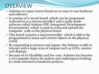
- 25. PIN-1 PC6 (RESET) Pin6 of PORTC Pin by default is used as RESET pin. PC6 can only be used as I/O pin when RSTDISBL Fuse is programmed. PIN-2 PD0 (RXD) Pin0 of PORTD RXD (Data Input Pin for USART) USART Serial Communication Interface [Can be used for programming] PIN-3 PD1 (TXD) Pin1 of PORTD TXD (Data Output Pin for USART) USART Serial Communication Interface [Can be used for programming] INT2( External Interrupt 2 Input)
- 26. PIN-4 PD2 (INT0) Pin2 of PORTD External Interrupt source 0 PIN-5 PD3 (INT1/OC2B) Pin3 of PORTD External Interrupt source1 OC2B(PWM - Timer/Counter2 Output Compare Match B Output) PIN-6 PD4 (XCK/T0) Pin4 of PORTD T0( Timer0 External Counter Input) XCK ( USART External Clock I/O) PIN-7 VCC Connected to positive voltage
- 27. PIN-8 GND Connected to ground PIN-9 PB6 (XTAL1/TOSC1) Pin6 of PORTB XTAL1 (Chip Clock Oscillator pin 1 or External clock input) TOSC1 (Timer Oscillator pin 1) PIN-10 PB7 (XTAL2/TOSC2) Pin7 of PORTB XTAL2 (Chip Clock Oscillator pin 2) TOSC2 (Timer Oscillator pin 2) PIN-11 PD5 (T1/OC0B) Pin5 of PORTD T1(Timer1 External Counter Input) OC0B(PWM - Timer/Counter0 Output Compare Match B Output)
- 28. PIN-12 PD6 (AIN0/OC0A) Pin6 of PORTD AIN0(Analog Comparator Positive I/P) OC0A(PWM - Timer/Counter0 Output Compare Match A Output) PIN-13 PD7 (AIN1) Pin7 of PORTD AIN1(Analog Comparator Negative I/P) PIN-14 PB0 (ICP1/CLKO) Pin0 of PORTB ICP1(Timer/Counter1 Input Capture Pin) CLKO (Divided System Clock. The divided system clock can be output on the PB0 pin)
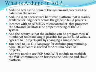
- 29. PIN-15 PB1 (OC1A) Pin1 of PORTB OC1A (Timer/Counter1 Output Compare Match A Output) PIN-16 PB2 (SS/OC1B) Pin2 of PORTB SS (SPI Slave Select Input). This pin is low when controller acts as slave. [Serial Peripheral Interface (SPI) for programming] OC1B (Timer/Counter1 Output Compare Match B Output) PIN-17 PB3 (MOSI/OC2A) Pin3 of PORTB MOSI (Master Output Slave Input). When controller acts as slave, the data is received by this pin. [Serial Peripheral Interface (SPI) for programming] OC2 (Timer/Counter2 Output Compare Match Output)
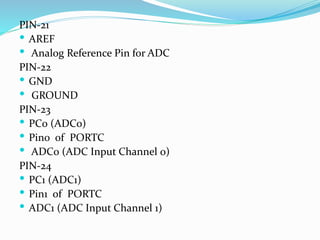
- 30. PIN-18 PB4 (MISO) Pin4 of PORTB MISO (Master Input Slave Output). When controller acts as slave, the data is sent to master by this controller through this pin. [Serial Peripheral Interface (SPI) for programming] PIN-19 PB5 (SCK) Pin5 of PORTB SCK (SPI Bus Serial Clock). This is the clock shared between this controller and other system for accurate data transfer. [Serial Peripheral Interface (SPI) for programming] PIN-20 AVCC Power for Internal ADC Converter
- 31. PIN-21 AREF Analog Reference Pin for ADC PIN-22 GND GROUND PIN-23 PC0 (ADC0) Pin0 of PORTC ADC0 (ADC Input Channel 0) PIN-24 PC1 (ADC1) Pin1 of PORTC ADC1 (ADC Input Channel 1)
- 32. PIN-25 PC2 (ADC2) Pin2 of PORTC ADC2 (ADC Input Channel 2) PIN-26 PC3 (ADC3) Pin3 of PORTC ADC3 (ADC Input Channel 3) PIN-27 PC4 (ADC4/SDA) Pin4 of PORTC ADC4 (ADC Input Channel 4) SDA (Two-wire Serial Bus Data Input/output Line) PN-28 PC5 (ADC5/SCL) Pin5 of PORTC ADC5 (ADC Input Channel 5) SCL (Two-wire Serial Bus Clock Line)
- 33. Basic working
- 34. The basic working of CPU of ATmega328:- 1. The data is uploaded in serial via the port (being uploaded from the computer’s Arduino IDE). The data is decoded and then the instructions are sent to instruction register and it decodes the instructions on the same clock pulse. 2. On the next clock pulse the next set of instructions are loaded in instruction register. 3. In general purpose registers the registers are of 8-bit but there are 3 16- bit registers also. a. 8-bit registers are used to store data for normal calculations and results. b. 16-bit registers are used to store data of timer counter in 2 different register. Eg. X-low & X-high. They are fast, and are used to store specific hardware functions. 4. EEPROM stores data permanently even if the power is cut out. Programming inside a EEPROM is slow. 5. Interrupt Unit checks whether there is an interrupt for the execution of instruction to be executed in ISR (Interrupt Service Routine). 6. Serial Peripheral Interface (SPI) is an interface bus commonly used to send data between microcontrollers and small peripherals such as Camera, Display, SD cards, etc. It uses separate clock and data lines, along with a select line to choose the device you wish to talk to.
- 35. 7.Watchdog timer is used to detect and recover from MCU malfunctioning. 8. Analog comparator compares the input values on the positive and negative pin, when the value of positive pin is higher the output is set. 9. Status and control is used to control the flow of execution of commands by checking other blocks inside the CPU at regular intervals. 10. ALU (Arithmetic and Logical unit)The high performance AVR ALU operates in direct connection with all the 32 general purpose working registers. Within a single clock cycle, arithmetic operations b/w general purpose registers are executed. The ALU operations are divided into 3 main categories – arithmetic, logical and bit-function. 11. I/O pins The digital inputs and outputs (digital I/O) on the Arduino are what allow you to connect the Arduino sensors, actuators, and other ICs. Learning how to use them will allow you to use the Arduino to do some really useful things, such as reading switch inputs, lighting indicators, and controlling relay outputs.
- 36. EXTRA: 1.Automatic (Software) Reset: Rather then requiring a physical press of the reset button before an upload, the Arduino is designed in a way that allows it to be reset by software running on a connected computer. The Arduino Software (IDE) uses this capability to allow you to upload code by simply pressing the upload button in the Arduino environment. This means that the bootloader can have a shorter timeout, as the lowering of DTR (Data Terminal Ready) can be well-coordinated with the start of the upload. 2.Firmware: Firmware is a software program or set of instructions programmed on a hardware device. It provides the necessary instructions for how the device communicates with the other computer hardware. Firmware is held in non-volatile memory devices such as ROM. 3.To check whether the firmware is installed in your Arduino or not just press the reset button and if the inbuilt LED flickers (on pin 13) the firmware is present.
- 37. Arduino - Installation The Arduino IDE is an open-source software, which is used to write and upload code to the Arduino boards. The IDE application is suitable for different operating systems such as Windows, Mac OS X, and Linux. It supports the programming languages C and C++. Here, IDE stands for Integrated Development Environment. The program or code written in the Arduino IDE is often called as sketching. We need to connect the Genuino and Arduino board with the IDE to upload the sketch written in the Arduino IDE software. The sketch is saved with the extension '.ino.'
- 38. Step 1 − First you must have your Arduino board (you can choose your favorite board) and a USB cable. In case you use Arduino UNO, Arduino Duemilanove, Nano, Arduino Mega 2560, or Diecimila, you will need a standard USB cable (A plug to B plug), the kind you would connect to a USB printer.
- 39. Step 2 − Download Arduino IDE Software. You can get different versions of Arduino IDE from the Download page on the Arduino Official website. You must select your software, which is compatible with your operating system (Windows, IOS, or Linux). After your file download is complete, unzip the file.
- 40. Step − Launch Arduino IDE. After your Arduino IDE software is downloaded, you need to unzip the folder. Inside the folder, you can find the application icon with an infinity label (application.exe). Double-click the icon to start the IDE.
- 41. Step 4 − Open your first project. Once the software starts, you have two options − Create a new project. To create a new project, select File → New
- 42. Step 5 − Select your Arduino board. To avoid any error while uploading your program to the board, you must select the correct Arduino board name, which matches with the board connected to your computer. Go to Tools → Board and select your board.
- 43. Step 6 − Select your serial port. Select the serial device of the Arduino board. Go to Tools → Serial Port menu. This is likely to be COM3 or higher (COM1 and COM2 are usually reserved for hardware serial ports).
- 44. The Arduino IDE will appear as:
- 45. Toolbar Button .UPLOAD The Upload button compiles and runs our code written on the screen. It further uploads the code to the connected board. Before uploading the sketch, we need to make sure that the correct board and ports are selected. We also need a USB connection to connect the board and the computer. Once all the above measures are done, click on the Upload button present on the toolbar. OPEN The Open button is used to open the already created file. The selected file will be opened in the current window. SAVE The save button is used to save the current sketch or code. NEW It is used to create a new sketch or opens a new window. VERIFY The Verify button is used to check the compilation error of the sketch or the written code. SERIAL MONITOR The serial monitor button is present on the right corner of the toolbar. It opens the serial monitor. When we connect the serial monitor, the board will reset on the operating system Windows, Linux. If we want to process the control characters in our sketch, we need to use an external terminal program. The terminal program should be connected to the COM port, which will be assigned when we connect the board to the computer.