SlideShare a Scribd company logo
F T ra n sf o                                                                                                                     F T ra n sf o
          PD                   rm                                                                                                           PD                   rm
      Y                                                                                                                                 Y
 Y


                                                                                                                                   Y
                                er


                                                                                                                                                                  er
ABB


                                                                                                                                  ABB
                          y


                                                                                                                                                            y
                       bu


                                                                                                                                                         bu
                                    2.0


                                                                                                                                                                      2.0
                     to


                                                                                                                                                       to
                  re


                                                                                                                                                    re
                                                                                                                    J3103/6/1
                he


                                                                                                                                                  he
           k


                                                                                                                                             k
          lic


                                                                                                                                            lic
                                          COMPUTER NUMERICAL CONTROL
      C


                                                                                                                                        C
      w                        om                                                                                                       w                        om
  w


                                                                                                                                    w
          w.                                                                                                                                w.
               A B B Y Y.c                                                                                                                       A B B Y Y.c


                                             UNIT 6

                                                     COMPUTER NUMERICAL CONTROL


                                                                     OBJECTIVES


                                               General Objective :To understand the concept and principles of computer
                                                                   numerical control (CNC) system.


                                               Specific Objectives : At the end of the unit you will be able to :

                                                              Ø    Understand the main components of the CNC system,

                                                              Ø    Understand the point-to-point system (positioning),

                                                              Ø    Understand the        contouring    system       (continuous
                                                                   system), and

                                                              Ø    Write a simple CNC milling program.
                                                                   .
F T ra n sf o                                                                                                                F T ra n sf o
          PD                   rm                                                                                                      PD                   rm
      Y                                                                                                                            Y
 Y


                                                                                                                              Y
                                er


                                                                                                                                                             er
ABB


                                                                                                                             ABB
                          y


                                                                                                                                                       y
                       bu


                                                                                                                                                    bu
                                    2.0


                                                                                                                                                                 2.0
                     to


                                                                                                                                                  to
                  re


                                                                                                                                               re
                                                                                                              J3103/6/2
                he


                                                                                                                                             he
           k


                                                                                                                                        k
          lic


                                                                                                                                       lic
                                          COMPUTER NUMERICAL CONTROL
      C


                                                                                                                                   C
      w                        om                                                                                                  w                        om
  w


                                                                                                                               w
          w.                                                                                                                           w.
               A B B Y Y.c                                                                                                                  A B B Y Y.c


                                                                          INPUT


                                          6.0 INTRODUCTION


                                                Computer numerical control is a system in which a control microcomputer
                                          is an integral part of a machine or a piece of equipment (onboard computer). The
                                          part programmes can be prepared at a remote site by programmer, and it may
                                          incorporate information obtained from drafting software packages and from
                                          machining simulations, in order to ensure that the part programme is bug free.
                                          The machine operator can, however, easily and manually programme onboard
                                          computers.    The operator can be modify the programs directly, prepare
                                          programme for different parts, and store the programmes.
                                                Because of the availability of small computers having a large memory,
                                          microprocessor(s), and programme-editing capabilities, CNC systems are widely
                                          used today. The availability of low-cost programmable controllers also played a
                                          major role in the successful implementation of CNC in manufacturing plants.
                                                Numerical Control is a system where machine action is created from the
                                          insertion of Numeric Data.    The Numeric Data is, in the beginning, written
                                          words in an easily understood code of letters and numbers (alphanumeric
                                          characters) known as a programme, which in turn is converted by the machine
                                          control unit (MCU) into the electrical signals used to control the machine
                                          movements.
F T ra n sf o                                                                                                                  F T ra n sf o
          PD                   rm                                                                                                        PD                   rm
      Y                                                                                                                              Y
 Y


                                                                                                                                Y
                                er


                                                                                                                                                               er
ABB


                                                                                                                               ABB
                          y


                                                                                                                                                         y
                       bu


                                                                                                                                                      bu
                                    2.0


                                                                                                                                                                   2.0
                     to


                                                                                                                                                    to
                  re


                                                                                                                                                 re
                                                                                                                J3103/6/3
                he


                                                                                                                                               he
           k


                                                                                                                                          k
          lic


                                                                                                                                         lic
                                          COMPUTER NUMERICAL CONTROL
      C


                                                                                                                                     C
      w                        om                                                                                                    w                        om
  w


                                                                                                                                 w
          w.                                                                                                                             w.
               A B B Y Y.c                                                                                                                    A B B Y Y.c


                                                The relationship between the words "Numerical" and "Control" is shown
                                          below.
                                                         NUMERICAL                                      CONTROL

                                             An instructional expression,                     To control such machine
                                             in a language of numbers,                        actions as:

                                             which represents a series of                      Directing        Altering
                                             commands for specific                             Commanding       Timing
                                                                                               Prescribing      Ceasing
                                             machine tool movements                            Sequencing       Guiding
                                                                                               Initiating


                                                Two important points should be made about N.C. First, the actual N.C.
                                          machine tool can do nothing more than it was capable of doing before a control
                                          unit was joined to it. There are now new metal removing principles involved.
                                          N.C. machines position and drive the cutting tools, but the same milling cutters,
                                          drills, taps, feeds, and other tools still perform the cutting operations. Cutting
                                          speeds, feeds, and tooling principles must still be adhered to.       Given this
                                          knowledge, what is the real advantage of numerical control?
                                                Primarily, the idle time or time to move into position for new cuts is
                                          limited only by the machine's capacity to respond. Because the machine receives
                                          commands from the machine control unit (MCU), it responds without hesitation.
                                          The actual utilisation rate or chip making rate is therefore much higher than on
                                          a manually operated machine.
                                                The second point is that numerical control machines can initiate nothing
                                          on their own. The machine accepts and responds to commands from the control
                                          unit. Even the control unit cannot think, judge, or reason. Without some input
                                          medium, e.g., punched tape or direct computer link, the machine and control
F T ra n sf o                                                                                                                 F T ra n sf o
          PD                   rm                                                                                                       PD                   rm
      Y                                                                                                                             Y
 Y


                                                                                                                               Y
                                er


                                                                                                                                                              er
ABB


                                                                                                                              ABB
                          y


                                                                                                                                                        y
                       bu


                                                                                                                                                     bu
                                    2.0


                                                                                                                                                                  2.0
                     to


                                                                                                                                                   to
                  re


                                                                                                                                                re
                                                                                                               J3103/6/4
                he


                                                                                                                                              he
           k


                                                                                                                                         k
          lic


                                                                                                                                        lic
                                          COMPUTER NUMERICAL CONTROL
      C


                                                                                                                                    C
      w                        om                                                                                                   w                        om
  w


                                                                                                                                w
          w.                                                                                                                            w.
               A B B Y Y.c                                                                                                                   A B B Y Y.c


                                          unit will do nothing. The N.C. Machine will perform only when the N.C. tape is
                                          prepared and loaded and cycle start is initiated.


                                          6.1. NC OPERATION


                                                CNC stands for Computer Numerical Control. An N.C. system in which a
                                          dedicated stored program computer is used to perform basic control functions.
                                                The functions of a CNC Controller are:
                                          1.     To read and store programme information.
                                          2.     To interpret the information in a logical command sequence.
                                          3.     To control the motion of the machines mechanical members.
                                          4.     To monitor the status of the machine.
                                                The interpretation of programme commands by a machine control unit
                                          and its conversion of those commands into machine motion is complex. The
                                          basic elements and operation of a typical NC machine are shown in Fig. 6.1. The
                                          functional elements in numerical control and the components involved follow:
                                                       a. Data input: The numerical information is read and stored in the
                                                          tape reader or in computer memory
                                                       b. Data processing: The programmes are read into the machine
                                                          control unit for processing.
                                                       c. Data output: This is information is translated into commands
                                                          (typically pulsed commands) to the servomotor (Fig. 6.2 and 6.3).
                                                          The servomotor then moves the table (on which the work piece is
                                                          mounted) to specific positions, through linear or rotary
                                                          movements, by means of stepping motors, leadscrews, and other
                                                          similar devices.
F T ra n sf o                                                                                                                                F T ra n sf o
          PD                   rm                                                                                                                      PD                   rm
      Y                                                                                                                                            Y
 Y


                                                                                                                                              Y
                                er


                                                                                                                                                                             er
ABB


                                                                                                                                             ABB
                          y


                                                                                                                                                                       y
                       bu


                                                                                                                                                                    bu
                                    2.0


                                                                                                                                                                                 2.0
                     to


                                                                                                                                                                  to
                  re


                                                                                                                                                               re
                                                                                                                                 J3103/6/5
                he


                                                                                                                                                             he
           k


                                                                                                                                                        k
          lic


                                                                                                                                                       lic
                                          COMPUTER NUMERICAL CONTROL
      C


                                                                                                                                                   C
      w                        om                                                                                                                  w                        om
  w


                                                                                                                                               w
          w.                                                                                                                                           w.
               A B B Y Y.c                                                                                                                                  A B B Y Y.c


                                                                                      Computer:
                                                                                    Input command,
                                                                                      Processing,
                                                                                    Output command


                                                                                                                Limit switches
                                                                Position feedback


                                                                                         Drive signal


                                             Figure 6.1. A schematic illustration of the major component
                                             of a computer numerical control machine tool


                                                                                                               Work table

                                                  Pulse train                       Stepping
                                                                                     motor              Gear

                                                                                                        Lead screw


                                              Figure 6.2. An open-loop control system for a numerical-control machine
F T ra n sf o                                                                                                                             F T ra n sf o
          PD                   rm                                                                                                                   PD                   rm
      Y                                                                                                                                         Y
 Y


                                                                                                                                           Y
                                er


                                                                                                                                                                          er
ABB


                                                                                                                                          ABB
                          y


                                                                                                                                                                    y
                       bu


                                                                                                                                                                 bu
                                    2.0


                                                                                                                                                                              2.0
                     to


                                                                                                                                                               to
                  re


                                                                                                                                                            re
                                                                                                                             J3103/6/6
                he


                                                                                                                                                          he
           k


                                                                                                                                                     k
          lic


                                                                                                                                                    lic
                                              COMPUTER NUMERICAL CONTROL
      C


                                                                                                                                                C
      w                        om                                                                                                               w                        om
  w


                                                                                                                                            w
          w.                                                                                                                                        w.
               A B B Y Y.c                                                                                                                               A B B Y Y.c


                                                                                                                     Work table

                                          Input                                                Dc
                                                        Comparator           DAC           servomotor      Gear

                                                                             Feedback signal            Lead screw      Position sensor


                                                  Figure 6.3. A closed-loop control system for a numerical-control machine


                                                  6.2. INDUSTRIAL APPLICATION


                                                       6.2.1. Metal Machining
                                                       Lathes of all types
                                                       Milling Machines of all types
                                                       Drilling Machines
                                                       Jig borers
                                                       Electric Discharge Machining (including wire cut machines)
                                                       Laser cutting machines
                                                       Machining centres
                                                       Turning centres
                                                       All types of grinding machines
                                                       Gear cutting machines


                                                       6.2.2. Metal Forming
                                                       Punching and nibbling
                                                       Guillotines
                                                       Flame cut and profiling
                                                       Folding
F T ra n sf o                                                                                                                      F T ra n sf o
          PD                   rm                                                                                                            PD                   rm
      Y                                                                                                                                  Y
 Y


                                                                                                                                    Y
                                er


                                                                                                                                                                   er
ABB


                                                                                                                                   ABB
                          y


                                                                                                                                                             y
                       bu


                                                                                                                                                          bu
                                    2.0


                                                                                                                                                                       2.0
                     to


                                                                                                                                                        to
                  re


                                                                                                                                                     re
                                                                                                                      J3103/6/7
                he


                                                                                                                                                   he
           k


                                                                                                                                              k
          lic


                                                                                                                                             lic
                                          COMPUTER NUMERICAL CONTROL
      C


                                                                                                                                         C
      w                        om                                                                                                        w                        om
  w


                                                                                                                                     w
          w.                                                                                                                                 w.
               A B B Y Y.c                                                                                                                        A B B Y Y.c


                                                Pipe bending
                                                Metal spinning


                                                6.2.3. Finishing
                                                Plating
                                                Painting


                                                6.2.4. Assembly Joining -
                                                Pick and place robots, spot and seam welding machines and robots,
                                                riveting, looming of wires and assembly of components into printed circuit
                                                boards.


                                          6.3. CNC AXIS CONVENTIONS


                                                CNC       axis   classification   follows   the   three-dimensional    Cartesian
                                          coordinate system and is established in BS 3635: 1972: Part 1. Fig. 5.3 shows the
                                          tree primary axes and the associated rotational axes.
                                                Most machines have two or three slide ways placed at right angles to one
                                          another. On CNC machines each slide is fitted with a control system, and is
                                          identified with either the letter X, Y or Z.
                                                Conventions have been adopted as to the naming of each axis. The axis of
                                          the main spindle, whether it is the axis of the tool spindle or the axis about
                                          which the work piece rotates is called the Z axis.
                                                The X axis is the motion of the largest travel of the primary movement (in
                                          case there is more than one).
F T ra n sf o                                                                                                                    F T ra n sf o
          PD                   rm                                                                                                          PD                   rm
      Y                                                                                                                                Y
 Y


                                                                                                                                  Y
                                er


                                                                                                                                                                 er
ABB


                                                                                                                                 ABB
                          y


                                                                                                                                                           y
                       bu


                                                                                                                                                        bu
                                    2.0


                                                                                                                                                                     2.0
                     to


                                                                                                                                                      to
                  re


                                                                                                                                                   re
                                                                                                                  J3103/6/8
                he


                                                                                                                                                 he
           k


                                                                                                                                            k
          lic


                                                                                                                                           lic
                                          COMPUTER NUMERICAL CONTROL
      C


                                                                                                                                       C
      w                        om                                                                                                      w                        om
  w


                                                                                                                                   w
          w.                                                                                                                               w.
               A B B Y Y.c                                                                                                                      A B B Y Y.c


                                                The Y axis then makes the third motion and is the shorter primary
                                          movement.
                                                In addition to these primary linear axes, there is provision for Rotary
                                          axes. They are designated A, B and C, with A rotary about the X axis, B rotary
                                          about the Y axis, and C rotary about the Z axis.
                                                It is often required to command a motion parallel to X, Y or Z axes within
                                          the realm of a secondary motion, or a tertiary motion within special automatic
                                          cycles such as describing the amount of finish allowance on a turned part, or to
                                          describe the distance of advancement of a drill during a drilling cycle etc. etc.


                                                                        Table 6.1. NC axes


                                                        Linear Axes              X           Y       Z
                                                        Rotary Axes              A           B       C
                                                        Secondary Linear         U           V       W
                                                        Interpolation            I           J       K


                                                Tertiary motion codes differ considerably, but the address characters
                                          variously used are P, Q, R, D, L, E, and H.
                                                The z-axis is parallel to the main spindle of the machine.          It will be
                                          horizontal on a lathe or horizontal machining centre and vertical on a vertical
                                          machining centre.


                                                The x-axis is always horizontal and at 90o to z.
                                                The y-axis is at right angles to both the x and z axes.
F T ra n sf o                                                                                                                F T ra n sf o
          PD                   rm                                                                                                      PD                   rm
      Y                                                                                                                            Y
 Y


                                                                                                                              Y
                                er


                                                                                                                                                             er
ABB


                                                                                                                             ABB
                          y


                                                                                                                                                       y
                       bu


                                                                                                                                                    bu
                                    2.0


                                                                                                                                                                 2.0
                     to


                                                                                                                                                  to
                  re


                                                                                                                                               re
                                                                                                                 J3103/6/9
                he


                                                                                                                                             he
           k


                                                                                                                                        k
          lic


                                                                                                                                       lic
                                          COMPUTER NUMERICAL CONTROL
      C


                                                                                                                                   C
      w                        om                                                                                                  w                        om
  w


                                                                                                                               w
          w.                                                                                                                           w.
               A B B Y Y.c                                                                                                                  A B B Y Y.c


                                                            spindle

                                                                                   rotation
                                                                                               table


                                                                              z
                                                                                        x


                                                                                              y


                                                               Figure 6.3. CNC axes


                                          6.4.   NC MACHINE SUB-UNIT


                                                 We have already seen the many and varied applications of numerical
                                          control to the manufacturing and other industries, now we will look at the
                                          methods of controlling machines. There are three sub units to study:


                                                       The machine tool itself.
                                                        The control unit.
                                                        The control system.
F T ra n sf o                                                                                                                  F T ra n sf o
          PD                   rm                                                                                                        PD                   rm
      Y                                                                                                                              Y
 Y


                                                                                                                                Y
                                er


                                                                                                                                                               er
ABB


                                                                                                                               ABB
                          y


                                                                                                                                                         y
                       bu


                                                                                                                                                      bu
                                    2.0


                                                                                                                                                                   2.0
                     to


                                                                                                                                                    to
                  re


                                                                                                                                                 re
                                                                                                               J3103/6/10
                he


                                                                                                                                               he
           k


                                                                                                                                          k
          lic


                                                                                                                                         lic
                                          COMPUTER NUMERICAL CONTROL
      C


                                                                                                                                     C
      w                        om                                                                                                    w                        om
  w


                                                                                                                                 w
          w.                                                                                                                             w.
               A B B Y Y.c                                                                                                                    A B B Y Y.c


                                               6.4.1.     The Machine Tool


                                                        A machine tool is a device designed to cut away surplus material
                                               and leave a component of the required shape and size. To do this a
                                               machine tool must be capable of:
                                               - Holding the work piece securely
                                               - Holding the cutting tool securely and driving it with suitable power.
                                               - Moving the tool and work piece relative to one another precisely enough
                                               to achieve accuracy of size and surface finish.
                                                        In addition, provision must be made for altering the spindle speed
                                               and feed rates, tool changing, supply of coolant etc. On a conventional
                                               machine an operator controls these functions and sets or alters them
                                               when he considers it necessary, the decision resulting from his training,
                                               skill and experience. Obviously, the machine settings may differ between
                                               operators as will the time taken to read scales, set positions, change tools,
                                               alter speeds and feeds, engage drives and set up the work piece etc. CNC
                                               Automatic Control can be applied to these functions and so result in
                                               consistent and reduced machining times through optimised cutting data,
                                               fast accurate positioning between cuts and fast automatic tool changing.


                                               6.4.2. The Control Unit


                                                        The CNC Machine Control Unit (MCU) has to read and decode the
                                               part programme, and to provide the decoded instructions to the control
                                               loops of the machine axes of motion, and to control the machine tool
                                               operations.
F T ra n sf o                                                                                                                F T ra n sf o
          PD                   rm                                                                                                      PD                   rm
      Y                                                                                                                            Y
 Y


                                                                                                                              Y
                                er


                                                                                                                                                             er
ABB


                                                                                                                             ABB
                          y


                                                                                                                                                       y
                       bu


                                                                                                                                                    bu
                                    2.0


                                                                                                                                                                 2.0
                     to


                                                                                                                                                  to
                  re


                                                                                                                                               re
                                                                                                               J3103/6/11
                he


                                                                                                                                             he
           k


                                                                                                                                        k
          lic


                                                                                                                                       lic
                                          COMPUTER NUMERICAL CONTROL
      C


                                                                                                                                   C
      w                        om                                                                                                  w                        om
  w


                                                                                                                               w
          w.                                                                                                                           w.
               A B B Y Y.c                                                                                                                  A B B Y Y.c


                                               The main grouping of parts of a control could be considered to be:
                                                            The Control Panel.
                                                            The Tape Reader,
                                                            The Processors
                                                     The first part of the control panel is the human interface that
                                               allows various modes of machine or control operation to be initiated, from
                                               switching on and homing, to programme loading and editing, to setting
                                               work positions and tool offsets, manually controlled movements and
                                               commencing the automatic cycling of a programme. Information about
                                               machine status and condition is available to the operator via VDU
                                               screens, gauges, meters, indicator lights and readouts.
                                                     The tape reader is the device used to transfer the programme
                                               information contained on a programme tape into the control unit. Most
                                               tape readers are of the photo-electric type which offers high speed reading
                                               with reliability and accuracy providing the tape is in good condition and
                                               the reader is kept clean and free of paper dust particles.
                                                     The processors within a control are the electronic circuits that
                                               permit conversion of part programme data into machine motions and they
                                               may be classified into two main sections. The data processing unit and
                                               the axis control processor. The function of the data processor is to decode
                                               the commands of the part program, process it and provide data to the axis
                                               control processor which then operates the slide drives and receives
                                               feedback signals on the actual position and velocity of each axis.
F T ra n sf o                                                                                                                    F T ra n sf o
          PD                   rm                                                                                                          PD                   rm
      Y                                                                                                                                Y
 Y


                                                                                                                                  Y
                                er


                                                                                                                                                                 er
ABB


                                                                                                                                 ABB
                          y


                                                                                                                                                           y
                       bu


                                                                                                                                                        bu
                                    2.0


                                                                                                                                                                     2.0
                     to


                                                                                                                                                      to
                  re


                                                                                                                                                   re
                                                                                                                 J3103/6/12
                he


                                                                                                                                                 he
           k


                                                                                                                                            k
          lic


                                                                                                                                           lic
                                          COMPUTER NUMERICAL CONTROL
      C


                                                                                                                                       C
      w                        om                                                                                                      w                        om
  w


                                                                                                                                   w
          w.                                                                                                                               w.
               A B B Y Y.c                                                                                                                      A B B Y Y.c


                                               The Data Processing Unit includes the following functions:
                                                     i. The input device, such a tape reader.
                                                     ii. Reading circuits and parity checking logic.
                                                     iii. Decoding circuits for distributing data to the controlled axes
                                                     iv. An interpolator to supply velocity commands to the axes, either
                                                         singly or in combination.
                                               The axis control processor consists of the following circuits:
                                                     i. Position control loops for each and all axes.
                                                     ii. Velocity control loops.
                                                     iii. Deceleration and backlash take up circuits.


                                                     An MCU is adaptable to virtually any machine, the differing control
                                               motions and codes being a result of the way the control has been
                                               programmed. This permanent resident program is known as an executive
                                               programme and resides in the read only memory (ROM) of the control,
                                               whereas the N.C. programme resides in the Random Access Memory
                                               (RAM). RAM allows external access and alteration if necessary, while
                                               ROM is programmed by the manufacturer and cannot be accessed through
                                               the control keyboard.


                                               6.4.3. Control System


                                                     There are two types of control systems used on NC machines. The
                                               point-to-point system and the continuous-path system.            Point-to-point
                                               systems are not so common these days, but they operate only in straight
                                               lines, which are suitable for positioning moves on a drilling machine or
                                               limited use on a lathe or milling machine, where at best 45% cuts are
                                               possible with two axes running continuous path controls allow angular
F T ra n sf o                                                                                                                 F T ra n sf o
          PD                   rm                                                                                                       PD                   rm
      Y                                                                                                                             Y
 Y


                                                                                                                               Y
                                er


                                                                                                                                                              er
ABB


                                                                                                                              ABB
                          y


                                                                                                                                                        y
                       bu


                                                                                                                                                     bu
                                    2.0


                                                                                                                                                                  2.0
                     to


                                                                                                                                                   to
                  re


                                                                                                                                                re
                                                                                                              J3103/6/13
                he


                                                                                                                                              he
           k


                                                                                                                                         k
          lic


                                                                                                                                        lic
                                          COMPUTER NUMERICAL CONTROL
      C


                                                                                                                                    C
      w                        om                                                                                                   w                        om
  w


                                                                                                                                w
          w.                                                                                                                            w.
               A B B Y Y.c                                                                                                                   A B B Y Y.c


                                                 path and radius motion because the control interpolator has the ability to
                                                 move the axis drive motors at varying velocities.
                                                       The point-to-point controls were NC controls, while the continuous
                                                 path controls could be NC or CNC controls.


                                          NOTE:        NC is a general term used for Numerical Control and is also a term
                                                       used to describe controls that run directly off tape. CNC is a
                                                       specific term for Computer Numerical Control. CNC Machines are
                                                       all NC machines, but NC controlled machines are not CNC
                                                       machines.


                                          6.5.   PROGRAM INPUT


                                                 Programmes can be produced and entered (loaded) by any of the following
                                          methods where available.
                                                        a.    Punched Tape
                                                        b.    Computer
                                                        c.    Direct Input


                                                 6.5.1. .Punched Tape


                                                       Punched tapes may be made of paper or plastic (Mylar) and have a
                                                 standard width of one inch (25.4mm) for the eight track (8 bit) format
                                                 used in numerical control.
                                                       A tape punch unit is connected to a teletype or similar keyboard
                                                 and produces a punched tape during typing of the program. Alternatively,
                                                 a punch unit can be connected to a personal computer (P.C.) and the
                                                 completed programme punched. The holes punched in the tape form
F T ra n sf o                                                                                                                F T ra n sf o
          PD                   rm                                                                                                      PD                   rm
      Y                                                                                                                            Y
 Y


                                                                                                                              Y
                                er


                                                                                                                                                             er
ABB


                                                                                                                             ABB
                          y


                                                                                                                                                       y
                       bu


                                                                                                                                                    bu
                                    2.0


                                                                                                                                                                 2.0
                     to


                                                                                                                                                  to
                  re


                                                                                                                                               re
                                                                                                             J3103/6/14
                he


                                                                                                                                             he
           k


                                                                                                                                        k
          lic


                                                                                                                                       lic
                                          COMPUTER NUMERICAL CONTROL
      C


                                                                                                                                   C
      w                        om                                                                                                  w                        om
  w


                                                                                                                               w
          w.                                                                                                                           w.
               A B B Y Y.c                                                                                                                  A B B Y Y.c


                                               certain patterns and the pattern represents a value when read by the tape
                                               reader on the MCU.
                                                     The pattern is a code in itself, and complies to a standard, either
                                               E.I.A. ( Electronics Industries Association ) which uses an odd number of
                                               holes or I.S.O. ( International Standards Organization ) which uses an
                                               even number of holes for each character. The I.S.O. code is most
                                               commonly used in Australia. The E.I.A. code is known as an odd parity
                                               system, and the I.S.O. code as an even parity system.
                                                     One of the tracks of each is assigned as a parity track and a hole is
                                               sometimes punched there automatically to maintain the parity. The
                                               purpose of parity is to check during tape reading for errors caused by
                                               unpunched holes, dirt or oil spots etc.


                                               6.5.2. Computers


                                                     Personal computers can be used to type the programme in its
                                               entirety while being visible on the screen, so mistakes can easily be
                                               spotted and corrected before the programme is loaded into the machine.
                                                     The programme can be down loaded to the machine via a
                                               connecting link (interface cable) or via punched tape if a punch unit is
                                               connected to a computer.


                                               6.5.3. Direct Input


                                                     Programming at the machine may eliminate the need for tape
                                               punching equipment and computers, but the machine is usually non-
                                               productive during this time.


                                                     Programming can be done by several methods, such as ;
F T ra n sf o                                                                                                               F T ra n sf o
          PD                   rm                                                                                                     PD                   rm
      Y                                                                                                                           Y
 Y


                                                                                                                             Y
                                er


                                                                                                                                                            er
ABB


                                                                                                                            ABB
                          y


                                                                                                                                                      y
                       bu


                                                                                                                                                   bu
                                    2.0


                                                                                                                                                                2.0
                     to


                                                                                                                                                 to
                  re


                                                                                                                                              re
                                                                                                            J3103/6/15
                he


                                                                                                                                            he
           k


                                                                                                                                       k
          lic


                                                                                                                                      lic
                                          COMPUTER NUMERICAL CONTROL
      C


                                                                                                                                  C
      w                        om                                                                                                 w                        om
  w


                                                                                                                              w
          w.                                                                                                                          w.
               A B B Y Y.c                                                                                                                 A B B Y Y.c


                                               - by typing the program directly into the memory of the M.C.U. through
                                                 the edit function.
                                               - programmes produced in this way can include all functions available, are
                                                stored in the machine ready for use at any time and can be output to a
                                                punch unit or computer for external storage.


                                               6.5.4. By Manual Data Input (M.D.I.)


                                                    M.D.I. may not allow all programming functions to operate, the
                                               programme can only be used once, and as it is not stored in the main
                                               memory cannot be output to an external device. Additionally, some
                                               controls allow only one line (block) of programme to be entered and
                                               executed at a time.


                                               6.5.5. Interactive Programming.


                                                     Some controls allow programming by a method that may be
                                               simpler and speedier than conventional N.C. program language. These
                                               methods usually take up considerable memory space and so fewer
                                               programmes could be stored in the M.C.U. than if they were prepared by
                                               N.C. language. Most of the controls allow
                                               for external storage of these programs providing the necessary devices are
                                               at hand. Interactive programming can also be known as "conversational",
                                               "symbolic", "blueprint","IGF" etc.
F T ra n sf o                                                                                                                    F T ra n sf o
          PD                   rm                                                                                                          PD                   rm
      Y                                                                                                                                Y
 Y


                                                                                                                                  Y
                                er


                                                                                                                                                                 er
ABB


                                                                                                                                 ABB
                          y


                                                                                                                                                           y
                       bu


                                                                                                                                                        bu
                                    2.0


                                                                                                                                                                     2.0
                     to


                                                                                                                                                      to
                  re


                                                                                                                                                   re
                                                                                                                  J3103/6/16
                he


                                                                                                                                                 he
           k


                                                                                                                                            k
          lic


                                                                                                                                           lic
                                          COMPUTER NUMERICAL CONTROL
      C


                                                                                                                                       C
      w                        om                                                                                                      w                        om
  w


                                                                                                                                   w
          w.                                                                                                                               w.
               A B B Y Y.c                                                                                                                      A B B Y Y.c


                                                 6.5.6. . External Devices.


                                                      A programme can be loaded directly from a P.C. as described, or from
                                                 other specialised units that have been designed as a portable device for
                                                 loading, transferring or storing N.C. programs. The devices may store the
                                                 information on floppy discs, hard discs, magnetic tape, or through solid
                                                 state circuitry. Those with discs or magnetic tape would be no larger than
                                                 a briefcase or perhaps a tissue box, down to pocket calculator size for solid
                                                 state devices.


                                                 NOTE: Where punched tape was once the only practical way for most
                                                 programmers to transfer (or load) their programs into the controls, it is
                                                 presently being overtaken by personal computers connected directly via
                                                 interface cable. Other popular and convenient methods are simply
                                                 through the edit mode or by interactive (conversational) programming.
                                                 Companies specialising in complex die work probably use DNC more often
                                                 now. Inputting through M.D.I. mode is common providing the restrictions
                                                 noted are adhered to.


                                          6.6.   NC PROGRAMMING


                                                 6.6.1. Job Planning
                                                 1. Sketch the part.               Add incremental or absolute dimensions.
                                                 2. Ascertain fixturing.           Select fixtures which have minimal projections
                                                                                   above the part.
                                                 3. Identify a set-up point.      Locate the set-up point near:
                                                                                  1. A corner of the part
                                                                                  2. A spot above the fixture
F T ra n sf o                                                                                                               F T ra n sf o
          PD                   rm                                                                                                     PD                   rm
      Y                                                                                                                           Y
 Y


                                                                                                                             Y
                                er


                                                                                                                                                            er
ABB


                                                                                                                            ABB
                          y


                                                                                                                                                      y
                       bu


                                                                                                                                                   bu
                                    2.0


                                                                                                                                                                2.0
                     to


                                                                                                                                                 to
                  re


                                                                                                                                              re
                                                                                                               J3103/6/17
                he


                                                                                                                                            he
           k


                                                                                                                                       k
          lic


                                                                                                                                      lic
                                          COMPUTER NUMERICAL CONTROL
      C


                                                                                                                                  C
      w                        om                                                                                                 w                        om
  w


                                                                                                                              w
          w.                                                                                                                          w.
               A B B Y Y.c                                                                                                                 A B B Y Y.c


                                                                               Consider space requirements for:
                                                                               1. Part loading and unloading
                                                                               2. Tool change.
                                               4. Plan operation sequence      Mark sequence pattern of sketch.
                                                                               Test program data for accuracy.
                                               5. Record necessary data for
                                                 each movement of the table
                                                 and tool on the program
                                                 sheet.
                                               6. Record instructions for      Identify, specific:
                                                 the machine operator.         1. Tools needed.
                                                                               2. Speed and feed data
                                                                               3. Tool change points
                                                                               4. Console switch setting


                                               6.6.2. Incremental


                                                        The word "incremental" may be defined as a dimension or a
                                               movement with respect to the preceding point in a prescribed sequence of
                                               points. Each positioning move is described quantitatively in distance and
                                               in direction from a previous point rather than from a fixed zero reference
                                               point.
F T ra n sf o                                                                                                                     F T ra n sf o
          PD                   rm                                                                                                           PD                   rm
      Y                                                                                                                                 Y
 Y


                                                                                                                                   Y
                                er


                                                                                                                                                                  er
ABB


                                                                                                                                  ABB
                          y


                                                                                                                                                            y
                       bu


                                                                                                                                                         bu
                                    2.0


                                                                                                                                                                      2.0
                     to


                                                                                                                                                       to
                  re


                                                                                                                                                    re
                                                                                                                  J3103/6/18
                he


                                                                                                                                                  he
           k


                                                                                                                                             k
          lic


                                                                                                                                            lic
                                          COMPUTER NUMERICAL CONTROL
      C


                                                                                                                                        C
      w                        om                                                                                                       w                        om
  w


                                                                                                                                    w
          w.                                                                                                                                w.
               A B B Y Y.c                                                                                                                       A B B Y Y.c


                                                            In incremental mode all moves are with respect to the last position
                                                 reached.


                                                                                           N10 G91
                                                 Y                                         N15   G01 X10.Y10.F300.
                                                                                           N20   Y10.
                                                                                           N25   X20.
                                            40                                             N30   X10.Y20.
                                            30                                             N35   X20-Y-30.
                                            20                                             N40   X-10.Y-10.
                                            10                                             N45   X-50.
                                                                                     X     N50   M02
                                                       10   20   30   40   50   60


                                                     6.6.3. Absolute


                                                            The data in the absolute system describes the next location always
                                                 in terms of its relationship to the fixed zero point. The zero point when
                                                 used as a programme datum is known as the programme origin.
                                                 The G90 code sets the control up in absolute mode. All moves are
                                                 performed with respect to the axes zero.
F T ra n sf o                                                                                                                 F T ra n sf o
          PD                   rm                                                                                                       PD                   rm
      Y                                                                                                                             Y
 Y


                                                                                                                               Y
                                er


                                                                                                                                                              er
ABB


                                                                                                                              ABB
                          y


                                                                                                                                                        y
                       bu


                                                                                                                                                     bu
                                    2.0


                                                                                                                                                                  2.0
                     to


                                                                                                                                                   to
                  re


                                                                                                                                                re
                                                                                                                 J3103/6/19
                he


                                                                                                                                              he
           k


                                                                                                                                         k
          lic


                                                                                                                                        lic
                                          COMPUTER NUMERICAL CONTROL
      C


                                                                                                                                    C
      w                        om                                                                                                   w                        om
  w


                                                                                                                                w
          w.                                                                                                                            w.
               A B B Y Y.c                                                                                                                   A B B Y Y.c


                                                                                            N10   G90
                                                    Y
                                                                                            N15   G01X10.Y10.F300.
                                                                                            N20   Y20.
                                                                                            N25   X30.
                                               40
                                                                                            N30   X40.Y40.
                                               30
                                               20
                                                                                            N35   X60.Y10.
                                                                                            N40   X50.Y0.
                                               10
                                                                                            N45   X0.
                                                        10   20   30   40   50   60         N50   M02


                                                6.6.4. Linear Interpolation


                                                           Under this command the machine tool will move in a straight line
                                                at a defined feed rate. Combined axis motions (angled moves) will be
                                                executed at the programming feed rate as the control will reduce the
                                                velocity of both axes accordingly.


                                                    E.g.          G01 X200. F250.
                                                    G01           Move in a straight line
                                                    X200.         A distance of 20O.mm
                                                    F250.         At a feed rate of 250.mm/min.


                                          NOTE: If a new line with G01 is listed again somewhere below, the F250 does
                                          not have to be written again. This is called modal.
F T ra n sf o                                                                                                                      F T ra n sf o
          PD                   rm                                                                                                            PD                   rm
      Y                                                                                                                                  Y
 Y


                                                                                                                                    Y
                                er


                                                                                                                                                                   er
ABB


                                                                                                                                   ABB
                          y


                                                                                                                                                             y
                       bu


                                                                                                                                                          bu
                                    2.0


                                                                                                                                                                       2.0
                     to


                                                                                                                                                        to
                  re


                                                                                                                                                     re
                                                                                                                 J3103/6/20
                he


                                                                                                                                                   he
           k


                                                                                                                                              k
          lic


                                                                                                                                             lic
                                          COMPUTER NUMERICAL CONTROL
      C


                                                                                                                                         C
      w                        om                                                                                                        w                        om
  w


                                                                                                                                     w
          w.                                                                                                                                 w.
               A B B Y Y.c                                                                                                                        A B B Y Y.c


                                          Example:


                                           A block as shown below is to be machined, write a program in absolute mode.


                                          %
                                                                                  10               70          10
                                                                                       10
                                          G90 -
                                          G01     X100      F300
                                                  Y70
                                           X90. Y80
                                                                    90


                                           X20.
                                                                             80


                                                                                                                              80
                                           X10. Y90.


                                                                                                                        70
                                           XO.     Y80
                                                   Y0.
                                                                                                 100
                                           M02


                                                  6.6.5. Circular Interpolation


                                                         In circular interpolation mode G02 will cause the path to be
                                                  transcribed in a clockwise direction and G03 will cause counter-clockwise
                                                  motion.


                                                  G02                    -    Clockwise
                                                  G03                    -    Counterclockwise


                                                  In circular interpolation there are a number of points to be remembered:
                                                  The end point of the arc is defined as X and Y coordinates exactly the
                                                  same as if commanding linear motion.
F T ra n sf o                                                                                                                    F T ra n sf o
          PD                   rm                                                                                                          PD                   rm
      Y                                                                                                                                Y
 Y


                                                                                                                                  Y
                                er


                                                                                                                                                                 er
ABB


                                                                                                                                 ABB
                          y


                                                                                                                                                           y
                       bu


                                                                                                                                                        bu
                                    2.0


                                                                                                                                                                     2.0
                     to


                                                                                                                                                      to
                  re


                                                                                                                                                   re
                                                                                                                    J3103/6/21
                he


                                                                                                                                                 he
           k


                                                                                                                                            k
          lic


                                                                                                                                           lic
                                          COMPUTER NUMERICAL CONTROL
      C


                                                                                                                                       C
      w                        om                                                                                                      w                        om
  w


                                                                                                                                   w
          w.                                                                                                                               w.
               A B B Y Y.c                                                                                                                      A B B Y Y.c


                                                 The centre of the arc is defined with respect to the start point in the I and
                                                 J words as an "increment" from this point.
                                                 For G02 and G03 to function the feed rate "F." must be specified.


                                          Example:


                                          N5%
                                          N10 G90
                                          N15 G01 Y110. F200.
                                          N20 G02 X20. I10.
                                          N25 G03 X30. Y100. I10.                     110

                                          N30 G01 X90.                                           All radius – R10

                                          N35 G02 X100. Y90. J-10.
                                          N40 G01 Y10,
                                          N45 G02 X90. Y0. I-10.
                                          N50 G01 X0.
                                                                                                        100
                                          N55 M02


                                          6.7.   PROGRAM DEFINITION


                                                 To enable the machine to operate automatically it is necessary to put into
                                          its memory a programme or set of instructions to carry out the required
                                          operation.
                                                 a) Programme.
                                                        A programme is a series of instructions to the machine, set out in
                                                 sequence to -produce a complete machining operation. A programme is
                                                 made up of a series of blocks.
F T ra n sf o                                                                                                                 F T ra n sf o
          PD                   rm                                                                                                       PD                   rm
      Y                                                                                                                             Y
 Y


                                                                                                                               Y
                                er


                                                                                                                                                              er
ABB


                                                                                                                              ABB
                          y


                                                                                                                                                        y
                       bu


                                                                                                                                                     bu
                                    2.0


                                                                                                                                                                  2.0
                     to


                                                                                                                                                   to
                  re


                                                                                                                                                re
                                                                                                               J3103/6/22
                he


                                                                                                                                              he
           k


                                                                                                                                         k
          lic


                                                                                                                                        lic
                                          COMPUTER NUMERICAL CONTROL
      C


                                                                                                                                    C
      w                        om                                                                                                   w                        om
  w


                                                                                                                                w
          w.                                                                                                                            w.
               A B B Y Y.c                                                                                                                   A B B Y Y.c


                                                b) Block.-
                                                         A block or programme line is a set of instructions to the machine
                                                that are carried out simultaneously. A block is made up of one or more
                                                Words and is terminated by an End of Block which is the Line Feed
                                                Character.


                                                c) Word.
                                                         A word is a specific instruction to the machine that will affect a
                                                particular machine function. Every word consists of a Letter Code and a
                                                Numerical value.


                                          Examples of Dimensional Words: X100. Y2.345 F0.25
                                          Examples of Non-Dimensional Words: N25 G90 M03 S1200


                                                Dimension words can be written in various ways, depending on the
                                          control. Let's take the examples X100. Y2.345 some older controls cannot accept
                                          decimal points, so both dimensional words would be written X100000 Y2345,
                                          with Y showing all decimal places. With these controls, if the X word was written
                                          as X100, it would be interpreted as one-tenth of a millimeter, not one hundred
                                          millimeters.
                                                If a control accepts decimal points, then ALL dimensional words should
                                          have a decimal point.      On any control, non-dimensional must NOT have a
                                          decimal point. The method of writing words beginning with a letter is known as
                                          word address format and is now almost universally used.
F T ra n sf o                                                                                                                 F T ra n sf o
          PD                   rm                                                                                                       PD                   rm
      Y                                                                                                                             Y
 Y


                                                                                                                               Y
                                er


                                                                                                                                                              er
ABB


                                                                                                                              ABB
                          y


                                                                                                                                                        y
                       bu


                                                                                                                                                     bu
                                    2.0


                                                                                                                                                                  2.0
                     to


                                                                                                                                                   to
                  re


                                                                                                                                                re
                                                                                                                J3103/6/23
                he


                                                                                                                                              he
           k


                                                                                                                                         k
          lic


                                                                                                                                        lic
                                          COMPUTER NUMERICAL CONTROL
      C


                                                                                                                                    C
      w                        om                                                                                                   w                        om
  w


                                                                                                                                w
          w.                                                                                                                            w.
               A B B Y Y.c                                                                                                                   A B B Y Y.c


                                                 6.7.1. Program


                                          (Start of Program)
                                          (Material 25.mm. dia.)
                                          (Grip 120.m.m. from Front of Jaws)
                                          N01 G71G90G95
                                          N02 G50X100.Z130.
                                          N03 S2000M03


                                             N04        G00X26.Z119.T0101                             BLOCK


                                           (Select Turning & Facing Tool)
                                           N05 GO1X2.F.O4
                                           N06 GOOZ120.
                                           N07 X24.                                             WORDS

                                           N08 G01Z20.                                N10 GOOX100. Z130. T0100

                                           N09 X26.
                                           N10 G00X100.Z130.T0100
                                           N11 M02


                                          WORD ADDRESS               The letter at the beginning of each word is called the
                                                                     address character.


                                          e.g.   XYZ           for   Axis designating word
                                                 F             for   Feed rates
                                                 G             for   Preparatory functions
                                                 M             for   miscellaneous function
                                                 N             for   Sequence numbers
F T ra n sf o                                                                                                                  F T ra n sf o
          PD                   rm                                                                                                        PD                   rm
      Y                                                                                                                              Y
 Y


                                                                                                                                Y
                                er


                                                                                                                                                               er
ABB


                                                                                                                               ABB
                          y


                                                                                                                                                         y
                       bu


                                                                                                                                                      bu
                                    2.0


                                                                                                                                                                   2.0
                     to


                                                                                                                                                    to
                  re


                                                                                                                                                 re
                                                                                                                J3103/6/24
                he


                                                                                                                                               he
           k


                                                                                                                                          k
          lic


                                                                                                                                         lic
                                          COMPUTER NUMERICAL CONTROL
      C


                                                                                                                                     C
      w                        om                                                                                                    w                        om
  w


                                                                                                                                 w
          w.                                                                                                                             w.
               A B B Y Y.c                                                                                                                    A B B Y Y.c


                                                CNC mills, drills and machining centers are all equipped with cycles to
                                          perform drilling, reaming, counter boring, boring and tapping operations. Some
                                          others have pocketing cycles, slot cutting cycles, hole pattern cycles etc, all of
                                          which are designed to save programming time and effort.
                                                CNC lathes usually have cycles to cover drilling, grooving/parting, screw
                                          cutting, repetitive cut (automatic roughing) operations and others. Each cycle
                                          has its own G code to control the sequence of motions and an accompanying set
                                          of words to define the parameters of those motions. These words have addresses
                                          such as: R,P,Q,D,E,I,K,H,B etc.


                                                 6.7.2. Program Preparation


                                                CNC programmes can be prepared manually, where the programmer
                                          usually roughs the programme out on paper, then produces it via a keyboard
                                          device of the type detailed below, or by assisted preparation in which a computer
                                          plays a predominant role -such as when CAD/CAM packages have been installed
                                          for design and programming.
                                                The programmer must posses knowledge and skills in planning machining
                                          sequences, fixturing, cutting data, cutting tools, calculations, as well as being
                                          familiar with the machines he is programming. To implement these skills to best
                                          effect a programmer should be prepared to observe critically his programs in use
                                          and modify them as necessary in order to gain maximum machine utilization.


                                                 6.7.3. Operation of program


                                                Before a machine can set into automatic motion a program must be
                                          checked for errors. A simple typing mistake - an incorrect code, a minus sign
                                          instead of a zero, the exclusion of a decimal etc, could cause and expensive
F T ra n sf o                                                                                                                             F T ra n sf o
          PD                   rm                                                                                                                   PD                   rm
      Y                                                                                                                                         Y
 Y


                                                                                                                                           Y
                                er


                                                                                                                                                                          er
ABB


                                                                                                                                          ABB
                          y


                                                                                                                                                                    y
                       bu


                                                                                                                                                                 bu
                                    2.0


                                                                                                                                                                              2.0
                     to


                                                                                                                                                               to
                  re


                                                                                                                                                            re
                                                                                                                           J3103/6/25
                he


                                                                                                                                                          he
           k


                                                                                                                                                     k
          lic


                                                                                                                                                    lic
                                          COMPUTER NUMERICAL CONTROL
      C


                                                                                                                                                C
      w                        om                                                                                                               w                        om
  w


                                                                                                                                            w
          w.                                                                                                                                        w.
               A B B Y Y.c                                                                                                                               A B B Y Y.c


                                          machine crash. Anyone who considers their programmes to be without error and
                                          not in need of careful and conscientious trialing has an attitude problem and is
                                          placing expensive machinery and operators safety at risk.
                                                There may be many ways in which a programme can be checked for
                                          errors, but a programme can only be proved 100% by running the machine and
                                          producing a part.
                                                Error checking can be performed in a variety of ways:
                                          Verification:       Read      through        the   print-out    (NOT       the   handwritten
                                                              manuscript) carefully - sometimes mistakes can be seen
                                                              easily.
                                          Trialing:           This involves the execution of the programme without
                                                              actually cutting the part and may be carried out in several
                                                              ways depending on the type of machine, or control, or even
                                                              the philosophy of the person in charge. Adhere to the later unless
                                                              you can put up good reasons for alteration.
                                                              Trialing usually consists of running the machinewith the single
                                                              block switch active, that is, each block will only be executed by
                                                              pressing cycle start, in conjunction with the programme
                                                              being displayed on the screen.
                                                              Quite often the dry run mode is switched on to hasten
                                                              Proceedings. 'Dry Run' results in all machine motion being
                                                              executed at a preset rate, usually in the region of 50% to 80%
                                                              of the rapid traverse capability of the machine. The actual axis
                                                              velocity   can      be    overridden       from   0%    to   100%.    The
                                                              disadvantage of dry running a programme is that feed rates will
                                                              be masked, and attention must be paid to determining the
                                                              actual programmed feed rate for each block. This may be
                                                              displayed on the screen.
F T ra n sf o                                                                                                                         F T ra n sf o
          PD                   rm                                                                                                               PD                   rm
      Y                                                                                                                                     Y
 Y


                                                                                                                                       Y
                                er


                                                                                                                                                                      er
ABB


                                                                                                                                      ABB
                          y


                                                                                                                                                                y
                       bu


                                                                                                                                                             bu
                                    2.0


                                                                                                                                                                          2.0
                     to


                                                                                                                                                           to
                  re


                                                                                                                                                        re
                                                                                                                   J3103/6/26
                he


                                                                                                                                                      he
           k


                                                                                                                                                 k
          lic


                                                                                                                                                lic
                                          COMPUTER NUMERICAL CONTROL
      C


                                                                                                                                            C
      w                        om                                                                                                           w                        om
  w


                                                                                                                                        w
          w.                                                                                                                                    w.
               A B B Y Y.c                                                                                                                           A B B Y Y.c


                                                              Every movement the machine makes during programme
                                                              trialing   should   be   expected   and   accountable     to      the
                                                              programmer, if not, those motions should be checked for
                                                              viability, and if necessary, a more thorough understanding of
                                                              the machine operation should be sought.


                                          Editing:             Wherever errors are found, they should be corrected and
                                                               rechecked, be it on the machine or at the programming
                                                               station. Whenever a programme is edited on the machine, a
                                                               note should be made on the print-out so the master or
                                                               original programme can also be corrected. A better method is
                                                               to punch out a programme from the control after successfully
                                                               producing a component.


                                          6.8.       TYPES OF CONTROL SYSTEM


                                                 There are two basic types of control systems in numerical control: point-
                                          to-point and contouring.
                                                 a. In a point-to-point system, also called positioning, each axis of the
                                                     machine is driven separately by lead screws and, depending on the
                                                     type of operation, at different velocities. The machine moves initially
                                                     at maximum velocity in order to reduce non-productive time, but
                                                     decelerates as the tool approaches its numerically defined position.
                                                     Thus, in an operation such as drilling (or punching a hole), the
                                                     positioning and cutting take place sequentially (Fig. 5.4).
F T ra n sf o                                                                                                                           F T ra n sf o
          PD                   rm                                                                                                                 PD                   rm
      Y                                                                                                                                       Y
 Y


                                                                                                                                         Y
                                er


                                                                                                                                                                        er
ABB


                                                                                                                                        ABB
                          y


                                                                                                                                                                  y
                       bu


                                                                                                                                                               bu
                                    2.0


                                                                                                                                                                            2.0
                     to


                                                                                                                                                             to
                  re


                                                                                                                                                          re
                                                                                                                           J3103/6/27
                he


                                                                                                                                                        he
           k


                                                                                                                                                   k
          lic


                                                                                                                                                  lic
                                          COMPUTER NUMERICAL CONTROL
      C


                                                                                                                                              C
      w                        om                                                                                                             w                        om
  w


                                                                                                                                          w
          w.                                                                                                                                      w.
               A B B Y Y.c                                                                                                                             A B B Y Y.c


                                                     After the hole is drilled or punched, the tool retracts upward and
                                                     moves rapidly to another position, and the operation is repeated. The
                                                     path followed from one position to another is important in only one
                                                     respect. It must be chosen to minimize the time of travel, for better
                                                     efficiency.        Point-to-point systems are used mainly in drilling,
                                                     punching, and straight milling operations.


                                                                            15
                                                                                  10       45
                                                                 C.P
                                                                       15
                                                                                  (0,0)


                                                                                                                  10
                                                                                       1                2


                                                                                       4               3           45


                                               Incremental (G90)                                       Absolute (G91)


                                          Position    Coordinate Coordinate                Position Coordinate          Coordinate
                                                           (X)                   (Y)                         (X)           (Y)
                                           C.P.            -15                   15             C.P.         -15           15
                                          Point 1          10                    -10        Point 1          25            -25
                                          Point 2          55                    -10        Point 2          45             0
                                          Point 3          55                    -55        Point 3          0             -45
                                          Point 4          10                    -55        Point 4          -45            0

                                                                Figure 5.4. Point-to point system
F T ra n sf o                                                                                                                     F T ra n sf o
          PD                   rm                                                                                                           PD                   rm
      Y                                                                                                                                 Y
 Y


                                                                                                                                   Y
                                er


                                                                                                                                                                  er
ABB


                                                                                                                                  ABB
                          y


                                                                                                                                                            y
                       bu


                                                                                                                                                         bu
                                    2.0


                                                                                                                                                                      2.0
                     to


                                                                                                                                                       to
                  re


                                                                                                                                                    re
                                                                                                                   J3103/6/28
                he


                                                                                                                                                  he
           k


                                                                                                                                             k
          lic


                                                                                                                                            lic
                                          COMPUTER NUMERICAL CONTROL
      C


                                                                                                                                        C
      w                        om                                                                                                       w                        om
  w


                                                                                                                                    w
          w.                                                                                                                                w.
               A B B Y Y.c                                                                                                                       A B B Y Y.c


                                                  b. In a contouring system (also known as a continuous path system), the
                                                  positioning and the operations are both performed along controlled paths
                                                  but at different velocities.      Because the tool acts as it travels along a
                                                  prescribed path (Fig. 5.5), accurate control and synchronization of
                                                  velocities and movements are important.           The contouring system is
                                                  typically used on lathes, milling machines, grinders, welding machinery,
                                                  and machining centres.

                                                     Cutter                                     Machined
                                                     radius                                      surface

                                                                                                        Cutter
                                                                                                        path


                                                                         Work piece


                                                       Figure 5.5. Continuous path by a milling cutter


                                          6.9.    PROGRAMMING CODES

                                                  A number of standard codes are used to reduce the amount of
                                          programming effort needed to command commonly used machining operations,
                                          instructions and conditions. These are commonly known as:
                                                 G codes – call up machining commands
                                                 M codes – call up machine control activities
                                                 T codes – call up tool selection
                                                 F codes – call up feed rates
                                                 S codes – call
F T ra n sf o                                                                                                               F T ra n sf o
          PD                   rm                                                                                                     PD                   rm
      Y                                                                                                                           Y
 Y


                                                                                                                             Y
                                er


                                                                                                                                                            er
ABB


                                                                                                                            ABB
                          y


                                                                                                                                                      y
                       bu


                                                                                                                                                   bu
                                    2.0


                                                                                                                                                                2.0
                     to


                                                                                                                                                 to
                  re


                                                                                                                                              re
                                                                                                              J3103/6/29
                he


                                                                                                                                            he
           k


                                                                                                                                       k
          lic


                                                                                                                                      lic
                                          COMPUTER NUMERICAL CONTROL
      C


                                                                                                                                  C
      w                        om                                                                                                 w                        om
  w


                                                                                                                              w
          w.                                                                                                                          w.
               A B B Y Y.c                                                                                                                 A B B Y Y.c


                                              - modal codes remain active after being entered, unless they are cancelled
                                               by another G code; and
                                              - non-modal codes are only active in the programme block in which they
                                               appear.


                                                 6.9.1. G codes (preparatory codes)

                                                 The majority of manufacturers follow the same practice in designation of
                                          codes, but their detailed implementation mav differ.


                                                Sample G codes
                                                GOO Rapid movement for position
                                                GOI      Linear interpolation used for straight-line feed
                                                G02      Circular interpolation, clockwise
                                                G03      Circular interpolartion, counterclockwise
                                                G04      Dwell, a programmed stop to the tool movement
                                                G17      Circular interpolation xy plane
                                                G18      Circular interpolation xz plane
                                                G19      Circular interpolation yz plane
                                                G20      Inch units
                                                G21      Millimetre units
                                                G28      Return to home position
                                                G29      Return from home position
                                                G31      Reverses programmed direction of x axis
                                                G32      Reverses programmed direction of y axis
                                                G41      Tool radius compensation left
                                                G42      Tool radius compensation right
                                                G43      Tool length compensation-positive direction
                                                G44      Tool length compensation-negative direction
F T ra n sf o                                                                                                             F T ra n sf o
          PD                   rm                                                                                                   PD                   rm
      Y                                                                                                                         Y
 Y


                                                                                                                           Y
                                er


                                                                                                                                                          er
ABB


                                                                                                                          ABB
                          y


                                                                                                                                                    y
                       bu


                                                                                                                                                 bu
                                    2.0


                                                                                                                                                              2.0
                     to


                                                                                                                                               to
                  re


                                                                                                                                            re
                                                                                                             J3103/6/30
                he


                                                                                                                                          he
           k


                                                                                                                                     k
          lic


                                                                                                                                    lic
                                          COMPUTER NUMERICAL CONTROL
      C


                                                                                                                                C
      w                        om                                                                                               w                        om
  w


                                                                                                                            w
          w.                                                                                                                        w.
               A B B Y Y.c                                                                                                               A B B Y Y.c


                                               G70   Imperial unit
                                               G71   Metric units
                                               G80   Cancel canned cycle
                                               G81   Drilling cycle
                                               G82   Drilling cycle with dwell
                                               G83   Deep hole drilling
                                               G84   Tapping cycle
                                               G85   89-boring cycles
                                               G90   Absolute mode
                                               G91   Incremental mode


                                               6.9.2. M codes


                                                     These control the auxiliary functions of the machine.
                                               MOO Program stop
                                               M02 End of program
                                               M03 Spindle on, clockwise
                                               M04 Spindle on, counter clockwise
                                               M05 Spindle off
                                               M06 Tool change
                                               M07 Oil mist coolant on
                                               M08 Flood coolant on
                                               M09 Coolant off
                                               M30 End of tape
F T ra n sf o                                                                                                                 F T ra n sf o
          PD                   rm                                                                                                       PD                   rm
      Y                                                                                                                             Y
 Y


                                                                                                                               Y
                                er


                                                                                                                                                              er
ABB


                                                                                                                              ABB
                          y


                                                                                                                                                        y
                       bu


                                                                                                                                                     bu
                                    2.0


                                                                                                                                                                  2.0
                     to


                                                                                                                                                   to
                  re


                                                                                                                                                re
                                                                                                                 J3103/6/31
                he


                                                                                                                                              he
           k


                                                                                                                                         k
          lic


                                                                                                                                        lic
                                           COMPUTER NUMERICAL CONTROL
      C


                                                                                                                                    C
      w                        om                                                                                                   w                        om
  w


                                                                                                                                w
          w.                                                                                                                            w.
               A B B Y Y.c                                                                                                                   A B B Y Y.c


                                            6.10. WRITING A PROGRAM


                                                             Figure 5.6. To cut a ‘S’-slot/groove with a point-to-point
                                                             method and a continuous path/contouring system

                                          Table 5. Reference points and X and Y coordinates to cut a ‘S’-slot/groove
                                           with a point-to-point method and a continuous path/contouring system


                                                           Position    Coordinate (X)    Coordinate (Y)
                                                             C.P.            0                  0
                                                             P. 1           45.0              -25.0
                                                             P. 2           70.0              -25.0
                                                             P. 3           60.0              -65.0
                                                             P. 4           45.0              -50.0
                                                             P. 5           60.0              -50.0
                                                             P. 6          49.393           -75.607
                                                             P. 7          38.787             -65.0
                                                             P. 8           15.0              -65.0
F T ra n sf o                                                                                                                 F T ra n sf o
          PD                   rm                                                                                                       PD                   rm
      Y                                                                                                                             Y
 Y


                                                                                                                               Y
                                er


                                                                                                                                                              er
ABB


                                                                                                                              ABB
                          y


                                                                                                                                                        y
                       bu


                                                                                                                                                     bu
                                    2.0


                                                                                                                                                                  2.0
                     to


                                                                                                                                                   to
                  re


                                                                                                                                                re
                                                                                                                 J3103/6/32
                he


                                                                                                                                              he
           k


                                                                                                                                         k
          lic


                                                                                                                                        lic
                                          COMPUTER NUMERICAL CONTROL
      C


                                                                                                                                    C
      w                        om                                                                                                   w                        om
  w


                                                                                                                                w
          w.                                                                                                                            w.
               A B B Y Y.c                                                                                                                   A B B Y Y.c


                                                 To machine the above component (as in Fig.5.6), below is the programme
                                           that can be followed;


                                           N10    G71 G90 S1500 T1                                    N130 G00 M00
                                           N20 G00 X0 Y0                                              N140 G00 X0 Y0
                                           N30 G00 X70.0 Y-25.0 Z10.0
                                           N40 G01                   Z-5.0 F250
                                           N50 G03 I-25.0 J0
                                           N60       X45.0 Y-50.0
                                           N70 G01 X60.0 Y -50.0
                                           N80 G02 I0 J-15.0
                                           N90        X49.393 Y-75.607
                                           N100 G01 X38.787 Y-65.0
                                           N110       X15.0 Y-65.0
                                           N120 Z10.0


                                           Description of The Above Programme


                                                 NXX – block number
                                                 Block No. 10 – set machine to use metric unit, incremental coordinate,
                                                 spindle speed 1500 rpm, choose tool no. 1.
                                                 Block No. 20 – rapid movement to centre point (C.P).
                                                 Block No. 30 - rapid movement to point 1 (P. 1), cutting tool distance is
                                                                5.0 mm from the surface of the work piece.
                                                 Block No. 40 – cutting tool cuts 10.00 mm deep, feed 250 mm/min
                                                 Block No. 50 – circular interpolation, counter clockwise, radius 25.0 mm
F T ra n sf o                                                                                                                  F T ra n sf o
          PD                   rm                                                                                                        PD                   rm
      Y                                                                                                                              Y
 Y


                                                                                                                                Y
                                er


                                                                                                                                                               er
ABB


                                                                                                                               ABB
                          y


                                                                                                                                                         y
                       bu


                                                                                                                                                      bu
                                    2.0


                                                                                                                                                                   2.0
                     to


                                                                                                                                                    to
                  re


                                                                                                                                                 re
                                                                                                                 J3103/6/33
                he


                                                                                                                                               he
           k


                                                                                                                                          k
          lic


                                                                                                                                         lic
                                          COMPUTER NUMERICAL CONTROL
      C


                                                                                                                                     C
      w                        om                                                                                                    w                        om
  w


                                                                                                                                 w
          w.                                                                                                                             w.
               A B B Y Y.c                                                                                                                    A B B Y Y.c


                                                  Block No. 60 – tool ends interpolation cutting at P. 4
                                                  Block No. 70 – linear interpolation until P. 5
                                                  Block No. 80 - circular interpolation, clockwise, radius 15.0 mm
                                                  Block No. 90 - tool ends interpolation cutting at P. 6
                                                  Block No. 100 - linear interpolation until P. 7
                                                  Block No. 110 - linear interpolation until P. 8
                                                  Block No. 120 – tool rises up 10.0 mm
                                                  Block No. 130 – program stops
                                                  Block No. 140 - rapid return to centre point (C.P).


                                          6.11.   ADVANTAGES OF COMPUTER NUMERICAL CONTROL


                                                  i.     The component programming tape and the tape reader are used
                                                         once only when the programme is copied into the computer
                                                         memory, not only this practice wills same time but it will also
                                                         reduce errors.
                                                  ii.    The programming tape can be edited on the shop floor, when the
                                                         machine is placed/located. Editing, correction and optimising; such
                                                         as machine tool operations, spindle speeds and speeds; are usually
                                                         done in the test run of the tape.
                                                  iii.   Computer numerical control can easily changes into metric system
                                                         if the programme is in the imperial units.
                                                  iv.    It is widely used in industry.        It is easily adaptable in a
                                                         computerised industry system.
                                                  v.     Increased flexibility – the machine can produce a specific part,
                                                         followed by other parts with different shapes, and at reduces cost.
                                                  vi.    Greater accuracy – computers have a higher sampling rate and
                                                         faster operation.
F T ra n sf o                                                                                                              F T ra n sf o
          PD                   rm                                                                                                    PD                   rm
      Y                                                                                                                          Y
 Y


                                                                                                                            Y
                                er


                                                                                                                                                           er
ABB


                                                                                                                           ABB
                          y


                                                                                                                                                     y
                       bu


                                                                                                                                                  bu
                                    2.0


                                                                                                                                                               2.0
                     to


                                                                                                                                                to
                  re


                                                                                                                                             re
                                                                                                             J3103/6/34
                he


                                                                                                                                           he
           k


                                                                                                                                      k
          lic


                                                                                                                                     lic
                                          COMPUTER NUMERICAL CONTROL
      C


                                                                                                                                 C
      w                        om                                                                                                w                        om
  w


                                                                                                                             w
          w.                                                                                                                         w.
               A B B Y Y.c                                                                                                                A B B Y Y.c


                                               vii.    More   versatility   –   editing   and   debugging    programmes,
                                                       reprogramming, and plotting and printing part shape are simpler.
                                               viii.   Programmes are stored on the machine ready for use.
                                               ix.     Programmes and data can be modified on the machine.
F T ra n sf o                                                                                                                           F T ra n sf o
          PD                   rm                                                                                                                 PD                   rm
      Y                                                                                                                                       Y
 Y


                                                                                                                                         Y
                                er


                                                                                                                                                                        er
ABB


                                                                                                                                        ABB
                          y


                                                                                                                                                                  y
                       bu


                                                                                                                                                               bu
                                    2.0


                                                                                                                                                                            2.0
                     to


                                                                                                                                                             to
                  re


                                                                                                                                                          re
                                                                                                                       J3103/6/35
                he


                                                                                                                                                        he
           k


                                                                                                                                                   k
          lic


                                                                                                                                                  lic
                                          COMPUTER NUMERICAL CONTROL
      C


                                                                                                                                              C
      w                        om                                                                                                             w                        om
  w


                                                                                                                                          w
          w.                                                                                                                                      w.
               A B B Y Y.c                                                                                                                             A B B Y Y.c


                                                                          ACTIVITY 6


                                          6.1.   Briefly state four (4) advantages of numerical control system.

                                          6.2.   You are given a drawing of a component. List down the steps you would take to
                                                 operate a NC machine in order produce the component.

                                          6.3.   Write a short paragraph on three (3) basic components of a numerical control system.
F T ra n sf o                                                                                                                   F T ra n sf o
          PD                   rm                                                                                                         PD                   rm
      Y                                                                                                                               Y
 Y


                                                                                                                                 Y
                                er


                                                                                                                                                                er
ABB


                                                                                                                                ABB
                          y


                                                                                                                                                          y
                       bu


                                                                                                                                                       bu
                                    2.0


                                                                                                                                                                    2.0
                     to


                                                                                                                                                     to
                  re


                                                                                                                                                  re
                                                                                                                  J3103/6/36
                he


                                                                                                                                                he
           k


                                                                                                                                           k
          lic


                                                                                                                                          lic
                                          COMPUTER NUMERICAL CONTROL
      C


                                                                                                                                      C
      w                        om                                                                                                     w                        om
  w


                                                                                                                                  w
          w.                                                                                                                              w.
               A B B Y Y.c                                                                                                                     A B B Y Y.c


                                                                          FEEDBACK ON ACTIVITY 6


                                          6.1.   The advantages of numerical control system are:
                                                 i.     The component programming tape and the tape reader are used
                                                         once only when the programme is copied into the computer
                                                         memory, not only this practice wills same time but it will also
                                                         reduce errors.
                                                 ii.     The programming tape can be edited on the shop floor, when the
                                                         machine is placed/located. Editing, correction and optimising; such
                                                         as machine tool operations, spindle speeds and speeds; are usually
                                                         done in the test run of the tape.
                                                 iii.    Computer numerical control can easily changes into metric system
                                                         if the program is in the imperial units.
                                                 iv.     It is widely used in industry.        It is easily adaptable in a
                                                         computerised industry system.
                                                 v.      Increased flexibility – the machine can produce a specific part,
                                                         followed by other parts with different shapes, and at reduces cost.
                                                 vi.     Greater accuracy – computers have a higher sampling rate and
                                                         faster operation.
                                                 vii.    More    versatility    –   editing    and    debugging     programs,
                                                         reprogramming, and plotting and printing part shape are simpler.
                                                 viii.   Programs are stored on the machine ready for use.
                                                 ix.     Programs and data can be modified on the machine.
F T ra n sf o                                                                                                                   F T ra n sf o
          PD                   rm                                                                                                         PD                   rm
      Y                                                                                                                               Y
 Y


                                                                                                                                 Y
                                er


                                                                                                                                                                er
ABB


                                                                                                                                ABB
                          y


                                                                                                                                                          y
                       bu


                                                                                                                                                       bu
                                    2.0


                                                                                                                                                                    2.0
                     to


                                                                                                                                                     to
                  re


                                                                                                                                                  re
                                                                                                                   J3103/6/37
                he


                                                                                                                                                he
           k


                                                                                                                                           k
          lic


                                                                                                                                          lic
                                          COMPUTER NUMERICAL CONTROL
      C


                                                                                                                                      C
      w                        om                                                                                                     w                        om
  w


                                                                                                                                  w
          w.                                                                                                                              w.
               A B B Y Y.c                                                                                                                     A B B Y Y.c


                                          6.2.   Job Planning
                                                 1. Sketch the part.               Add incremental or absolute dimensions.
                                                 2. Ascertain fixturing.           Select fixtures which have minimal projections
                                                                                   above the part.
                                                 3. Identify a set-up point.       Locate the set-up point near:
                                                                                  1. A corner of the part
                                                                                  2. A spot above the fixture


                                                                                  Consider space requirements for:
                                                                                  1. Part loading and unloading
                                                                                  2. Tool change.
                                                 4. Plan operation sequence       Mark sequence pattern of sketch.
                                                                                  Test program data for accuracy.
                                                 5. Record necessary data for
                                                   each movement of the table
                                                   and tool on the program
                                                   sheet.
                                                 6. Record instructions for       Identify, specific:
                                                   the machine operator.          1. Tools needed.
                                                                                  2. Speed and feed data
                                                                                  3. Tool change points
                                                                                  4. Console switch setting


                                          6.3.(a) Machine Tool - a device designed to cut away surplus material and leave
                                          a component of the required shape and size. It holds the work piece, cutting tool
                                          and moves the tool and work piece relative to one another precisely enough to
                                          achieve accuracy of size and surface finish. It can also alter the spindle speed
                                          and feed rates, tool changing, supply of coolant etc.
F T ra n sf o                                                                                                              F T ra n sf o
          PD                   rm                                                                                                    PD                   rm
      Y                                                                                                                          Y
 Y


                                                                                                                            Y
                                er


                                                                                                                                                           er
ABB


                                                                                                                           ABB
                          y


                                                                                                                                                     y
                       bu


                                                                                                                                                  bu
                                    2.0


                                                                                                                                                               2.0
                     to


                                                                                                                                                to
                  re


                                                                                                                                             re
                                                                                                            J3103/6/38
                he


                                                                                                                                           he
           k


                                                                                                                                      k
          lic


                                                                                                                                     lic
                                          COMPUTER NUMERICAL CONTROL
      C


                                                                                                                                 C
      w                        om                                                                                                w                        om
  w


                                                                                                                             w
          w.                                                                                                                         w.
               A B B Y Y.c                                                                                                                A B B Y Y.c


                                            (b) The Control Unit - reads, decodes the part programme and provides the
                                               decoded instructions to the control loops of the machine axes of motion,
                                               and to control the machine tool operations. There are three main parts of
                                               the control unit namely, the Control Panel, the Tape Reader and the
                                               Processors


                                            (c) Control system - there are two types of control systems used on NC
                                               machines - the point-to-point system and the continuous-path system.
                                               The point-to-point systems operates only in straight lines, which are
                                               suitable for positioning moves on a drilling machine or limited use on a
                                               lathe or milling machine, where at best 45% cuts are possible with two
                                               axes running continuous path controls allow angular path and radius
                                               motion because the control interpolator has the ability to move the axis
                                               drive motors at varying velocities. The point-to-point controls were NC
                                               controls, while the continuous path controls could be NC or CNC controls.
F T ra n sf o                                                                                                                         F T ra n sf o
          PD                   rm                                                                                                               PD                   rm
      Y                                                                                                                                     Y
 Y


                                                                                                                                       Y
                                er


                                                                                                                                                                      er
ABB


                                                                                                                                      ABB
                          y


                                                                                                                                                                y
                       bu


                                                                                                                                                             bu
                                    2.0


                                                                                                                                                                          2.0
                     to


                                                                                                                                                           to
                  re


                                                                                                                                                        re
                                                                                                                    J3103/6/39
                he


                                                                                                                                                      he
           k


                                                                                                                                                 k
          lic


                                                                                                                                                lic
                                          COMPUTER NUMERICAL CONTROL
      C


                                                                                                                                            C
      w                        om                                                                                                           w                        om
  w


                                                                                                                                        w
          w.                                                                                                                                    w.
               A B B Y Y.c                                                                                                                           A B B Y Y.c


                                                                        SELF-ASSESSMENT 6


                                          1. Numerical control machine can be done in absolute coordinate (G90) and incremental
                                             coordinates (G91). What is the difference between the two coordinates.

                                          2. By using G90 and G 91 coordinates write a program to cut a component in is the .below
                                             figure.


                                                                   30


                                                                                                            J20
                                                 70


                                                                                                                                 35


                                                                                             20
                                                                                                   60
F T ra n sf o                                                                                                                 F T ra n sf o
          PD                   rm                                                                                                       PD                   rm
      Y                                                                                                                             Y
 Y


                                                                                                                               Y
                                er


                                                                                                                                                              er
ABB


                                                                                                                              ABB
                          y


                                                                                                                                                        y
                       bu


                                                                                                                                                     bu
                                    2.0


                                                                                                                                                                  2.0
                     to


                                                                                                                                                   to
                  re


                                                                                                                                                re
                                                                                                                 J3103/6/40
                he


                                                                                                                                              he
           k


                                                                                                                                         k
          lic


                                                                                                                                        lic
                                          COMPUTER NUMERICAL CONTROL
      C


                                                                                                                                    C
      w                        om                                                                                                   w                        om
  w


                                                                                                                                w
          w.                                                                                                                            w.
               A B B Y Y.c                                                                                                                   A B B Y Y.c


                                                          FEEDBACK OF SELF-ASSESSMENT 6


                                          1. (a) G90   Absolute mode - The data in the absolute system describes the next
                                                location always in terms of its relationship to the fixed zero point. The
                                                zero point when used as a programme datum is known as the programme
                                                origin. All moves are performed with respect to the axes zero.


                                          1. (b) G91   Incremental mode - dimension or a movement with respect to the
                                                preceding point in a prescribed sequence of points. Each positioning move
                                                is described quantitatively in distance and in direction from a previous
                                                points rather than from a fixed zero reference point.


                                          2.
                                                                       G 90                              G 91
                                               Point
                                                                 X               Y                X                  Y
                                           Origin Point          0                0                0                 0
                                                1               30               -70              30                -70
                                                2               30               -40               0                 30
                                                3               70               -15              40                 25
                                                4               90               -35              20                -20
                                                5               90               -70               0                -35
F T ra n sf o                             F T ra n sf o
          PD                   rm                   PD                   rm
      Y                                         Y
 Y


                                           Y
                                er


                                                                          er
ABB


                                          ABB
                          y


                                                                    y
                       bu


                                                                 bu
                                    2.0


                                                                              2.0
                     to


                                                               to
                  re


                                                            re
                he


                                                          he
           k


                                                     k
          lic


                                                    lic
      C


                                                C
      w                        om               w                        om
  w


                                            w
          w.                                        w.
               A B B Y Y.c                               A B B Y Y.c

More Related Content

PDF
Unit4 Surface Texture
PDF
Drill
PDF
Unit3 Gear
PDF
Pengukuran Micrometer1
PDF
Pengukuran Vernier1
PDF
Unit2 Gear
PDF
Unit1 Screw Thread
PDF
Unit5 Power Press Machine
Unit4 Surface Texture
Drill
Unit3 Gear
Pengukuran Micrometer1
Pengukuran Vernier1
Unit2 Gear
Unit1 Screw Thread
Unit5 Power Press Machine

What's hot (14)

PDF
Unit7 Shielded Gas Arc Welding
PDF
Hands Tool
PDF
Lscty11 lotus live
PDF
Practicing English
PDF
Search and Structure Design of Physiologically Active Compounds
PDF
REACH
PDF
Chemical Similarity
PDF
CADASTER
PPT
Flat plan template 2
PDF
Обучение с помощью мобильных технологий
PDF
Informed Cities: Live vote results 1
PDF
Social Media for Social Change | SVP Tokyo 2/21/10
PPT
Chapter 4 bj ts dc biasing
PPTX
Sarigiannis biological connectivity in cra
Unit7 Shielded Gas Arc Welding
Hands Tool
Lscty11 lotus live
Practicing English
Search and Structure Design of Physiologically Active Compounds
REACH
Chemical Similarity
CADASTER
Flat plan template 2
Обучение с помощью мобильных технологий
Informed Cities: Live vote results 1
Social Media for Social Change | SVP Tokyo 2/21/10
Chapter 4 bj ts dc biasing
Sarigiannis biological connectivity in cra
Ad

Viewers also liked (16)

PDF
Unit 3 Computer Numerical Control
PPS
Humour devoir civique
PDF
Cnc turning lecture6
DOC
Labsheet cnc turning jj503
PDF
Cnc turning lecture6
DOC
Resolucao189 06
PPT
Rotary encoder training material
PPTX
Nc Technology
PPTX
Cnc control system and interface
PDF
24 cnc machine feedback devices
PPSX
Cnc 2- structure of cnc machines - hiast
PPTX
DNC SYSTEMS
PPTX
NC, CNC & DNC Machine
PPT
Basic Geometrical Dimensioning & Tolerancing Tranning
PPT
Manufacturing
PDF
Gd&T Presentation1111
Unit 3 Computer Numerical Control
Humour devoir civique
Cnc turning lecture6
Labsheet cnc turning jj503
Cnc turning lecture6
Resolucao189 06
Rotary encoder training material
Nc Technology
Cnc control system and interface
24 cnc machine feedback devices
Cnc 2- structure of cnc machines - hiast
DNC SYSTEMS
NC, CNC & DNC Machine
Basic Geometrical Dimensioning & Tolerancing Tranning
Manufacturing
Gd&T Presentation1111
Ad

Similar to Unit6 Computer Numerical Control (20)

PDF
Unit4 Surface Texture
PDF
Unit3 Gear
PDF
IBM Lotus Notes&Domino today
PDF
Unit1 Screw Thread
PDF
Unit2 Gear
PDF
Unit5 Power Press Machine
PDF
Unit0 J3103
PDF
Unit0 J3103
PDF
Molecular Chirality
PDF
Budget2009
PDF
Lscty11 connections
PDF
Unit7 Shielded Gas Arc Welding
PDF
MODELOS DE CASAS III
PDF
Pri of phs 9th
PDF
Eye's Delight (Qurratul-^Ayn)
PDF
Employer Brand
PDF
Web20 forbusiness2
PDF
Web20 forbusiness
PDF
Ecm projects : where to start from ?
PDF
Testing Techniques For Agile Testers - Janet Gregory
Unit4 Surface Texture
Unit3 Gear
IBM Lotus Notes&Domino today
Unit1 Screw Thread
Unit2 Gear
Unit5 Power Press Machine
Unit0 J3103
Unit0 J3103
Molecular Chirality
Budget2009
Lscty11 connections
Unit7 Shielded Gas Arc Welding
MODELOS DE CASAS III
Pri of phs 9th
Eye's Delight (Qurratul-^Ayn)
Employer Brand
Web20 forbusiness2
Web20 forbusiness
Ecm projects : where to start from ?
Testing Techniques For Agile Testers - Janet Gregory

More from mokhtar (20)

PPT
AR101 -POLIBRIGED ( PERTOLONGAN CEMAS)
PPT
Chapter 1: Hand Tools
PPT
Engineering Drawing: Chapter 13 roles of engineering drawing
PPT
Engineering Drawing: Chapter 12 working drawing
PPT
Engineering Drawing: Chapter 11 thread fastener
PPT
Engineering Drawing: Chapter 10 convention in section
PPT
Engineering Drawing: Chapter 09 section
PPT
Engineering Drawing: Chapter 08 orthographic convention
PPT
Engineering Drawing: Chapter 07 dimensioning
PPT
Engineering Drawing: Chapter 05 pictorial sketching
PPT
Engineering Drawing: Chapter 04 orthographic writing
PPT
Engineering Drawing: Chapter 02 using drawing tools
PPT
Engineering Drawing: Chapter 01 introduction
DOC
Kedua 2002
DOC
Jul 2009
DOC
Jul 2008
DOC
Jan 2009
DOC
Jul 2007
DOC
Jul 2006
DOC
Jul 2005
AR101 -POLIBRIGED ( PERTOLONGAN CEMAS)
Chapter 1: Hand Tools
Engineering Drawing: Chapter 13 roles of engineering drawing
Engineering Drawing: Chapter 12 working drawing
Engineering Drawing: Chapter 11 thread fastener
Engineering Drawing: Chapter 10 convention in section
Engineering Drawing: Chapter 09 section
Engineering Drawing: Chapter 08 orthographic convention
Engineering Drawing: Chapter 07 dimensioning
Engineering Drawing: Chapter 05 pictorial sketching
Engineering Drawing: Chapter 04 orthographic writing
Engineering Drawing: Chapter 02 using drawing tools
Engineering Drawing: Chapter 01 introduction
Kedua 2002
Jul 2009
Jul 2008
Jan 2009
Jul 2007
Jul 2006
Jul 2005

Recently uploaded (20)

PDF
NewMind AI Weekly Chronicles - August'25 Week I
PDF
The Rise and Fall of 3GPP – Time for a Sabbatical?
PDF
Encapsulation_ Review paper, used for researhc scholars
PDF
Empathic Computing: Creating Shared Understanding
PPTX
sap open course for s4hana steps from ECC to s4
PDF
Spectral efficient network and resource selection model in 5G networks
PDF
Architecting across the Boundaries of two Complex Domains - Healthcare & Tech...
PDF
Diabetes mellitus diagnosis method based random forest with bat algorithm
PPT
Teaching material agriculture food technology
PDF
Agricultural_Statistics_at_a_Glance_2022_0.pdf
PDF
Per capita expenditure prediction using model stacking based on satellite ima...
PDF
Chapter 3 Spatial Domain Image Processing.pdf
PDF
Building Integrated photovoltaic BIPV_UPV.pdf
PDF
Profit Center Accounting in SAP S/4HANA, S4F28 Col11
PPTX
20250228 LYD VKU AI Blended-Learning.pptx
PDF
Unlocking AI with Model Context Protocol (MCP)
PDF
MIND Revenue Release Quarter 2 2025 Press Release
PDF
How UI/UX Design Impacts User Retention in Mobile Apps.pdf
PDF
Network Security Unit 5.pdf for BCA BBA.
PPTX
Effective Security Operations Center (SOC) A Modern, Strategic, and Threat-In...
NewMind AI Weekly Chronicles - August'25 Week I
The Rise and Fall of 3GPP – Time for a Sabbatical?
Encapsulation_ Review paper, used for researhc scholars
Empathic Computing: Creating Shared Understanding
sap open course for s4hana steps from ECC to s4
Spectral efficient network and resource selection model in 5G networks
Architecting across the Boundaries of two Complex Domains - Healthcare & Tech...
Diabetes mellitus diagnosis method based random forest with bat algorithm
Teaching material agriculture food technology
Agricultural_Statistics_at_a_Glance_2022_0.pdf
Per capita expenditure prediction using model stacking based on satellite ima...
Chapter 3 Spatial Domain Image Processing.pdf
Building Integrated photovoltaic BIPV_UPV.pdf
Profit Center Accounting in SAP S/4HANA, S4F28 Col11
20250228 LYD VKU AI Blended-Learning.pptx
Unlocking AI with Model Context Protocol (MCP)
MIND Revenue Release Quarter 2 2025 Press Release
How UI/UX Design Impacts User Retention in Mobile Apps.pdf
Network Security Unit 5.pdf for BCA BBA.
Effective Security Operations Center (SOC) A Modern, Strategic, and Threat-In...

Unit6 Computer Numerical Control

  • 1. F T ra n sf o F T ra n sf o PD rm PD rm Y Y Y Y er er ABB ABB y y bu bu 2.0 2.0 to to re re J3103/6/1 he he k k lic lic COMPUTER NUMERICAL CONTROL C C w om w om w w w. w. A B B Y Y.c A B B Y Y.c UNIT 6 COMPUTER NUMERICAL CONTROL OBJECTIVES General Objective :To understand the concept and principles of computer numerical control (CNC) system. Specific Objectives : At the end of the unit you will be able to : Ø Understand the main components of the CNC system, Ø Understand the point-to-point system (positioning), Ø Understand the contouring system (continuous system), and Ø Write a simple CNC milling program. .
  • 2. F T ra n sf o F T ra n sf o PD rm PD rm Y Y Y Y er er ABB ABB y y bu bu 2.0 2.0 to to re re J3103/6/2 he he k k lic lic COMPUTER NUMERICAL CONTROL C C w om w om w w w. w. A B B Y Y.c A B B Y Y.c INPUT 6.0 INTRODUCTION Computer numerical control is a system in which a control microcomputer is an integral part of a machine or a piece of equipment (onboard computer). The part programmes can be prepared at a remote site by programmer, and it may incorporate information obtained from drafting software packages and from machining simulations, in order to ensure that the part programme is bug free. The machine operator can, however, easily and manually programme onboard computers. The operator can be modify the programs directly, prepare programme for different parts, and store the programmes. Because of the availability of small computers having a large memory, microprocessor(s), and programme-editing capabilities, CNC systems are widely used today. The availability of low-cost programmable controllers also played a major role in the successful implementation of CNC in manufacturing plants. Numerical Control is a system where machine action is created from the insertion of Numeric Data. The Numeric Data is, in the beginning, written words in an easily understood code of letters and numbers (alphanumeric characters) known as a programme, which in turn is converted by the machine control unit (MCU) into the electrical signals used to control the machine movements.
  • 3. F T ra n sf o F T ra n sf o PD rm PD rm Y Y Y Y er er ABB ABB y y bu bu 2.0 2.0 to to re re J3103/6/3 he he k k lic lic COMPUTER NUMERICAL CONTROL C C w om w om w w w. w. A B B Y Y.c A B B Y Y.c The relationship between the words "Numerical" and "Control" is shown below. NUMERICAL CONTROL An instructional expression, To control such machine in a language of numbers, actions as: which represents a series of Directing Altering commands for specific Commanding Timing Prescribing Ceasing machine tool movements Sequencing Guiding Initiating Two important points should be made about N.C. First, the actual N.C. machine tool can do nothing more than it was capable of doing before a control unit was joined to it. There are now new metal removing principles involved. N.C. machines position and drive the cutting tools, but the same milling cutters, drills, taps, feeds, and other tools still perform the cutting operations. Cutting speeds, feeds, and tooling principles must still be adhered to. Given this knowledge, what is the real advantage of numerical control? Primarily, the idle time or time to move into position for new cuts is limited only by the machine's capacity to respond. Because the machine receives commands from the machine control unit (MCU), it responds without hesitation. The actual utilisation rate or chip making rate is therefore much higher than on a manually operated machine. The second point is that numerical control machines can initiate nothing on their own. The machine accepts and responds to commands from the control unit. Even the control unit cannot think, judge, or reason. Without some input medium, e.g., punched tape or direct computer link, the machine and control
  • 4. F T ra n sf o F T ra n sf o PD rm PD rm Y Y Y Y er er ABB ABB y y bu bu 2.0 2.0 to to re re J3103/6/4 he he k k lic lic COMPUTER NUMERICAL CONTROL C C w om w om w w w. w. A B B Y Y.c A B B Y Y.c unit will do nothing. The N.C. Machine will perform only when the N.C. tape is prepared and loaded and cycle start is initiated. 6.1. NC OPERATION CNC stands for Computer Numerical Control. An N.C. system in which a dedicated stored program computer is used to perform basic control functions. The functions of a CNC Controller are: 1. To read and store programme information. 2. To interpret the information in a logical command sequence. 3. To control the motion of the machines mechanical members. 4. To monitor the status of the machine. The interpretation of programme commands by a machine control unit and its conversion of those commands into machine motion is complex. The basic elements and operation of a typical NC machine are shown in Fig. 6.1. The functional elements in numerical control and the components involved follow: a. Data input: The numerical information is read and stored in the tape reader or in computer memory b. Data processing: The programmes are read into the machine control unit for processing. c. Data output: This is information is translated into commands (typically pulsed commands) to the servomotor (Fig. 6.2 and 6.3). The servomotor then moves the table (on which the work piece is mounted) to specific positions, through linear or rotary movements, by means of stepping motors, leadscrews, and other similar devices.
  • 5. F T ra n sf o F T ra n sf o PD rm PD rm Y Y Y Y er er ABB ABB y y bu bu 2.0 2.0 to to re re J3103/6/5 he he k k lic lic COMPUTER NUMERICAL CONTROL C C w om w om w w w. w. A B B Y Y.c A B B Y Y.c Computer: Input command, Processing, Output command Limit switches Position feedback Drive signal Figure 6.1. A schematic illustration of the major component of a computer numerical control machine tool Work table Pulse train Stepping motor Gear Lead screw Figure 6.2. An open-loop control system for a numerical-control machine
  • 6. F T ra n sf o F T ra n sf o PD rm PD rm Y Y Y Y er er ABB ABB y y bu bu 2.0 2.0 to to re re J3103/6/6 he he k k lic lic COMPUTER NUMERICAL CONTROL C C w om w om w w w. w. A B B Y Y.c A B B Y Y.c Work table Input Dc Comparator DAC servomotor Gear Feedback signal Lead screw Position sensor Figure 6.3. A closed-loop control system for a numerical-control machine 6.2. INDUSTRIAL APPLICATION 6.2.1. Metal Machining Lathes of all types Milling Machines of all types Drilling Machines Jig borers Electric Discharge Machining (including wire cut machines) Laser cutting machines Machining centres Turning centres All types of grinding machines Gear cutting machines 6.2.2. Metal Forming Punching and nibbling Guillotines Flame cut and profiling Folding
  • 7. F T ra n sf o F T ra n sf o PD rm PD rm Y Y Y Y er er ABB ABB y y bu bu 2.0 2.0 to to re re J3103/6/7 he he k k lic lic COMPUTER NUMERICAL CONTROL C C w om w om w w w. w. A B B Y Y.c A B B Y Y.c Pipe bending Metal spinning 6.2.3. Finishing Plating Painting 6.2.4. Assembly Joining - Pick and place robots, spot and seam welding machines and robots, riveting, looming of wires and assembly of components into printed circuit boards. 6.3. CNC AXIS CONVENTIONS CNC axis classification follows the three-dimensional Cartesian coordinate system and is established in BS 3635: 1972: Part 1. Fig. 5.3 shows the tree primary axes and the associated rotational axes. Most machines have two or three slide ways placed at right angles to one another. On CNC machines each slide is fitted with a control system, and is identified with either the letter X, Y or Z. Conventions have been adopted as to the naming of each axis. The axis of the main spindle, whether it is the axis of the tool spindle or the axis about which the work piece rotates is called the Z axis. The X axis is the motion of the largest travel of the primary movement (in case there is more than one).
  • 8. F T ra n sf o F T ra n sf o PD rm PD rm Y Y Y Y er er ABB ABB y y bu bu 2.0 2.0 to to re re J3103/6/8 he he k k lic lic COMPUTER NUMERICAL CONTROL C C w om w om w w w. w. A B B Y Y.c A B B Y Y.c The Y axis then makes the third motion and is the shorter primary movement. In addition to these primary linear axes, there is provision for Rotary axes. They are designated A, B and C, with A rotary about the X axis, B rotary about the Y axis, and C rotary about the Z axis. It is often required to command a motion parallel to X, Y or Z axes within the realm of a secondary motion, or a tertiary motion within special automatic cycles such as describing the amount of finish allowance on a turned part, or to describe the distance of advancement of a drill during a drilling cycle etc. etc. Table 6.1. NC axes Linear Axes X Y Z Rotary Axes A B C Secondary Linear U V W Interpolation I J K Tertiary motion codes differ considerably, but the address characters variously used are P, Q, R, D, L, E, and H. The z-axis is parallel to the main spindle of the machine. It will be horizontal on a lathe or horizontal machining centre and vertical on a vertical machining centre. The x-axis is always horizontal and at 90o to z. The y-axis is at right angles to both the x and z axes.
  • 9. F T ra n sf o F T ra n sf o PD rm PD rm Y Y Y Y er er ABB ABB y y bu bu 2.0 2.0 to to re re J3103/6/9 he he k k lic lic COMPUTER NUMERICAL CONTROL C C w om w om w w w. w. A B B Y Y.c A B B Y Y.c spindle rotation table z x y Figure 6.3. CNC axes 6.4. NC MACHINE SUB-UNIT We have already seen the many and varied applications of numerical control to the manufacturing and other industries, now we will look at the methods of controlling machines. There are three sub units to study: The machine tool itself. The control unit. The control system.
  • 10. F T ra n sf o F T ra n sf o PD rm PD rm Y Y Y Y er er ABB ABB y y bu bu 2.0 2.0 to to re re J3103/6/10 he he k k lic lic COMPUTER NUMERICAL CONTROL C C w om w om w w w. w. A B B Y Y.c A B B Y Y.c 6.4.1. The Machine Tool A machine tool is a device designed to cut away surplus material and leave a component of the required shape and size. To do this a machine tool must be capable of: - Holding the work piece securely - Holding the cutting tool securely and driving it with suitable power. - Moving the tool and work piece relative to one another precisely enough to achieve accuracy of size and surface finish. In addition, provision must be made for altering the spindle speed and feed rates, tool changing, supply of coolant etc. On a conventional machine an operator controls these functions and sets or alters them when he considers it necessary, the decision resulting from his training, skill and experience. Obviously, the machine settings may differ between operators as will the time taken to read scales, set positions, change tools, alter speeds and feeds, engage drives and set up the work piece etc. CNC Automatic Control can be applied to these functions and so result in consistent and reduced machining times through optimised cutting data, fast accurate positioning between cuts and fast automatic tool changing. 6.4.2. The Control Unit The CNC Machine Control Unit (MCU) has to read and decode the part programme, and to provide the decoded instructions to the control loops of the machine axes of motion, and to control the machine tool operations.
  • 11. F T ra n sf o F T ra n sf o PD rm PD rm Y Y Y Y er er ABB ABB y y bu bu 2.0 2.0 to to re re J3103/6/11 he he k k lic lic COMPUTER NUMERICAL CONTROL C C w om w om w w w. w. A B B Y Y.c A B B Y Y.c The main grouping of parts of a control could be considered to be: The Control Panel. The Tape Reader, The Processors The first part of the control panel is the human interface that allows various modes of machine or control operation to be initiated, from switching on and homing, to programme loading and editing, to setting work positions and tool offsets, manually controlled movements and commencing the automatic cycling of a programme. Information about machine status and condition is available to the operator via VDU screens, gauges, meters, indicator lights and readouts. The tape reader is the device used to transfer the programme information contained on a programme tape into the control unit. Most tape readers are of the photo-electric type which offers high speed reading with reliability and accuracy providing the tape is in good condition and the reader is kept clean and free of paper dust particles. The processors within a control are the electronic circuits that permit conversion of part programme data into machine motions and they may be classified into two main sections. The data processing unit and the axis control processor. The function of the data processor is to decode the commands of the part program, process it and provide data to the axis control processor which then operates the slide drives and receives feedback signals on the actual position and velocity of each axis.
  • 12. F T ra n sf o F T ra n sf o PD rm PD rm Y Y Y Y er er ABB ABB y y bu bu 2.0 2.0 to to re re J3103/6/12 he he k k lic lic COMPUTER NUMERICAL CONTROL C C w om w om w w w. w. A B B Y Y.c A B B Y Y.c The Data Processing Unit includes the following functions: i. The input device, such a tape reader. ii. Reading circuits and parity checking logic. iii. Decoding circuits for distributing data to the controlled axes iv. An interpolator to supply velocity commands to the axes, either singly or in combination. The axis control processor consists of the following circuits: i. Position control loops for each and all axes. ii. Velocity control loops. iii. Deceleration and backlash take up circuits. An MCU is adaptable to virtually any machine, the differing control motions and codes being a result of the way the control has been programmed. This permanent resident program is known as an executive programme and resides in the read only memory (ROM) of the control, whereas the N.C. programme resides in the Random Access Memory (RAM). RAM allows external access and alteration if necessary, while ROM is programmed by the manufacturer and cannot be accessed through the control keyboard. 6.4.3. Control System There are two types of control systems used on NC machines. The point-to-point system and the continuous-path system. Point-to-point systems are not so common these days, but they operate only in straight lines, which are suitable for positioning moves on a drilling machine or limited use on a lathe or milling machine, where at best 45% cuts are possible with two axes running continuous path controls allow angular
  • 13. F T ra n sf o F T ra n sf o PD rm PD rm Y Y Y Y er er ABB ABB y y bu bu 2.0 2.0 to to re re J3103/6/13 he he k k lic lic COMPUTER NUMERICAL CONTROL C C w om w om w w w. w. A B B Y Y.c A B B Y Y.c path and radius motion because the control interpolator has the ability to move the axis drive motors at varying velocities. The point-to-point controls were NC controls, while the continuous path controls could be NC or CNC controls. NOTE: NC is a general term used for Numerical Control and is also a term used to describe controls that run directly off tape. CNC is a specific term for Computer Numerical Control. CNC Machines are all NC machines, but NC controlled machines are not CNC machines. 6.5. PROGRAM INPUT Programmes can be produced and entered (loaded) by any of the following methods where available. a. Punched Tape b. Computer c. Direct Input 6.5.1. .Punched Tape Punched tapes may be made of paper or plastic (Mylar) and have a standard width of one inch (25.4mm) for the eight track (8 bit) format used in numerical control. A tape punch unit is connected to a teletype or similar keyboard and produces a punched tape during typing of the program. Alternatively, a punch unit can be connected to a personal computer (P.C.) and the completed programme punched. The holes punched in the tape form
  • 14. F T ra n sf o F T ra n sf o PD rm PD rm Y Y Y Y er er ABB ABB y y bu bu 2.0 2.0 to to re re J3103/6/14 he he k k lic lic COMPUTER NUMERICAL CONTROL C C w om w om w w w. w. A B B Y Y.c A B B Y Y.c certain patterns and the pattern represents a value when read by the tape reader on the MCU. The pattern is a code in itself, and complies to a standard, either E.I.A. ( Electronics Industries Association ) which uses an odd number of holes or I.S.O. ( International Standards Organization ) which uses an even number of holes for each character. The I.S.O. code is most commonly used in Australia. The E.I.A. code is known as an odd parity system, and the I.S.O. code as an even parity system. One of the tracks of each is assigned as a parity track and a hole is sometimes punched there automatically to maintain the parity. The purpose of parity is to check during tape reading for errors caused by unpunched holes, dirt or oil spots etc. 6.5.2. Computers Personal computers can be used to type the programme in its entirety while being visible on the screen, so mistakes can easily be spotted and corrected before the programme is loaded into the machine. The programme can be down loaded to the machine via a connecting link (interface cable) or via punched tape if a punch unit is connected to a computer. 6.5.3. Direct Input Programming at the machine may eliminate the need for tape punching equipment and computers, but the machine is usually non- productive during this time. Programming can be done by several methods, such as ;
  • 15. F T ra n sf o F T ra n sf o PD rm PD rm Y Y Y Y er er ABB ABB y y bu bu 2.0 2.0 to to re re J3103/6/15 he he k k lic lic COMPUTER NUMERICAL CONTROL C C w om w om w w w. w. A B B Y Y.c A B B Y Y.c - by typing the program directly into the memory of the M.C.U. through the edit function. - programmes produced in this way can include all functions available, are stored in the machine ready for use at any time and can be output to a punch unit or computer for external storage. 6.5.4. By Manual Data Input (M.D.I.) M.D.I. may not allow all programming functions to operate, the programme can only be used once, and as it is not stored in the main memory cannot be output to an external device. Additionally, some controls allow only one line (block) of programme to be entered and executed at a time. 6.5.5. Interactive Programming. Some controls allow programming by a method that may be simpler and speedier than conventional N.C. program language. These methods usually take up considerable memory space and so fewer programmes could be stored in the M.C.U. than if they were prepared by N.C. language. Most of the controls allow for external storage of these programs providing the necessary devices are at hand. Interactive programming can also be known as "conversational", "symbolic", "blueprint","IGF" etc.
  • 16. F T ra n sf o F T ra n sf o PD rm PD rm Y Y Y Y er er ABB ABB y y bu bu 2.0 2.0 to to re re J3103/6/16 he he k k lic lic COMPUTER NUMERICAL CONTROL C C w om w om w w w. w. A B B Y Y.c A B B Y Y.c 6.5.6. . External Devices. A programme can be loaded directly from a P.C. as described, or from other specialised units that have been designed as a portable device for loading, transferring or storing N.C. programs. The devices may store the information on floppy discs, hard discs, magnetic tape, or through solid state circuitry. Those with discs or magnetic tape would be no larger than a briefcase or perhaps a tissue box, down to pocket calculator size for solid state devices. NOTE: Where punched tape was once the only practical way for most programmers to transfer (or load) their programs into the controls, it is presently being overtaken by personal computers connected directly via interface cable. Other popular and convenient methods are simply through the edit mode or by interactive (conversational) programming. Companies specialising in complex die work probably use DNC more often now. Inputting through M.D.I. mode is common providing the restrictions noted are adhered to. 6.6. NC PROGRAMMING 6.6.1. Job Planning 1. Sketch the part. Add incremental or absolute dimensions. 2. Ascertain fixturing. Select fixtures which have minimal projections above the part. 3. Identify a set-up point. Locate the set-up point near: 1. A corner of the part 2. A spot above the fixture
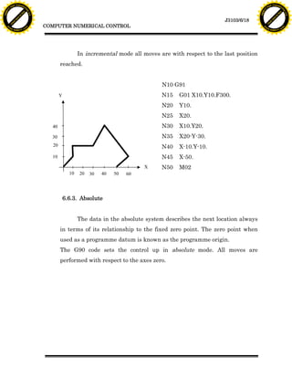
  • 17. F T ra n sf o F T ra n sf o PD rm PD rm Y Y Y Y er er ABB ABB y y bu bu 2.0 2.0 to to re re J3103/6/17 he he k k lic lic COMPUTER NUMERICAL CONTROL C C w om w om w w w. w. A B B Y Y.c A B B Y Y.c Consider space requirements for: 1. Part loading and unloading 2. Tool change. 4. Plan operation sequence Mark sequence pattern of sketch. Test program data for accuracy. 5. Record necessary data for each movement of the table and tool on the program sheet. 6. Record instructions for Identify, specific: the machine operator. 1. Tools needed. 2. Speed and feed data 3. Tool change points 4. Console switch setting 6.6.2. Incremental The word "incremental" may be defined as a dimension or a movement with respect to the preceding point in a prescribed sequence of points. Each positioning move is described quantitatively in distance and in direction from a previous point rather than from a fixed zero reference point.
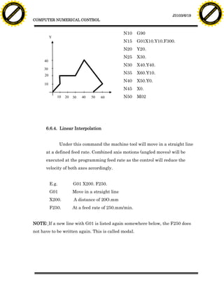
  • 18. F T ra n sf o F T ra n sf o PD rm PD rm Y Y Y Y er er ABB ABB y y bu bu 2.0 2.0 to to re re J3103/6/18 he he k k lic lic COMPUTER NUMERICAL CONTROL C C w om w om w w w. w. A B B Y Y.c A B B Y Y.c In incremental mode all moves are with respect to the last position reached. N10 G91 Y N15 G01 X10.Y10.F300. N20 Y10. N25 X20. 40 N30 X10.Y20. 30 N35 X20-Y-30. 20 N40 X-10.Y-10. 10 N45 X-50. X N50 M02 10 20 30 40 50 60 6.6.3. Absolute The data in the absolute system describes the next location always in terms of its relationship to the fixed zero point. The zero point when used as a programme datum is known as the programme origin. The G90 code sets the control up in absolute mode. All moves are performed with respect to the axes zero.
  • 19. F T ra n sf o F T ra n sf o PD rm PD rm Y Y Y Y er er ABB ABB y y bu bu 2.0 2.0 to to re re J3103/6/19 he he k k lic lic COMPUTER NUMERICAL CONTROL C C w om w om w w w. w. A B B Y Y.c A B B Y Y.c N10 G90 Y N15 G01X10.Y10.F300. N20 Y20. N25 X30. 40 N30 X40.Y40. 30 20 N35 X60.Y10. N40 X50.Y0. 10 N45 X0. 10 20 30 40 50 60 N50 M02 6.6.4. Linear Interpolation Under this command the machine tool will move in a straight line at a defined feed rate. Combined axis motions (angled moves) will be executed at the programming feed rate as the control will reduce the velocity of both axes accordingly. E.g. G01 X200. F250. G01 Move in a straight line X200. A distance of 20O.mm F250. At a feed rate of 250.mm/min. NOTE: If a new line with G01 is listed again somewhere below, the F250 does not have to be written again. This is called modal.
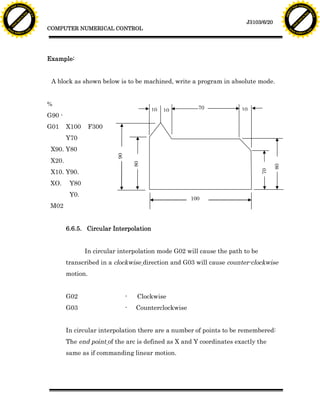
  • 20. F T ra n sf o F T ra n sf o PD rm PD rm Y Y Y Y er er ABB ABB y y bu bu 2.0 2.0 to to re re J3103/6/20 he he k k lic lic COMPUTER NUMERICAL CONTROL C C w om w om w w w. w. A B B Y Y.c A B B Y Y.c Example: A block as shown below is to be machined, write a program in absolute mode. % 10 70 10 10 G90 - G01 X100 F300 Y70 X90. Y80 90 X20. 80 80 X10. Y90. 70 XO. Y80 Y0. 100 M02 6.6.5. Circular Interpolation In circular interpolation mode G02 will cause the path to be transcribed in a clockwise direction and G03 will cause counter-clockwise motion. G02 - Clockwise G03 - Counterclockwise In circular interpolation there are a number of points to be remembered: The end point of the arc is defined as X and Y coordinates exactly the same as if commanding linear motion.
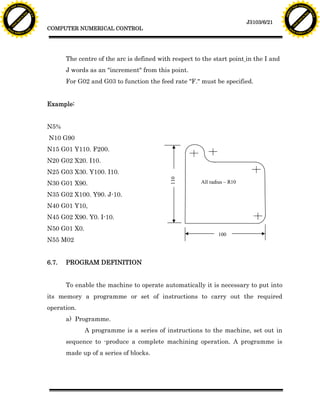
  • 21. F T ra n sf o F T ra n sf o PD rm PD rm Y Y Y Y er er ABB ABB y y bu bu 2.0 2.0 to to re re J3103/6/21 he he k k lic lic COMPUTER NUMERICAL CONTROL C C w om w om w w w. w. A B B Y Y.c A B B Y Y.c The centre of the arc is defined with respect to the start point in the I and J words as an "increment" from this point. For G02 and G03 to function the feed rate "F." must be specified. Example: N5% N10 G90 N15 G01 Y110. F200. N20 G02 X20. I10. N25 G03 X30. Y100. I10. 110 N30 G01 X90. All radius – R10 N35 G02 X100. Y90. J-10. N40 G01 Y10, N45 G02 X90. Y0. I-10. N50 G01 X0. 100 N55 M02 6.7. PROGRAM DEFINITION To enable the machine to operate automatically it is necessary to put into its memory a programme or set of instructions to carry out the required operation. a) Programme. A programme is a series of instructions to the machine, set out in sequence to -produce a complete machining operation. A programme is made up of a series of blocks.
  • 22. F T ra n sf o F T ra n sf o PD rm PD rm Y Y Y Y er er ABB ABB y y bu bu 2.0 2.0 to to re re J3103/6/22 he he k k lic lic COMPUTER NUMERICAL CONTROL C C w om w om w w w. w. A B B Y Y.c A B B Y Y.c b) Block.- A block or programme line is a set of instructions to the machine that are carried out simultaneously. A block is made up of one or more Words and is terminated by an End of Block which is the Line Feed Character. c) Word. A word is a specific instruction to the machine that will affect a particular machine function. Every word consists of a Letter Code and a Numerical value. Examples of Dimensional Words: X100. Y2.345 F0.25 Examples of Non-Dimensional Words: N25 G90 M03 S1200 Dimension words can be written in various ways, depending on the control. Let's take the examples X100. Y2.345 some older controls cannot accept decimal points, so both dimensional words would be written X100000 Y2345, with Y showing all decimal places. With these controls, if the X word was written as X100, it would be interpreted as one-tenth of a millimeter, not one hundred millimeters. If a control accepts decimal points, then ALL dimensional words should have a decimal point. On any control, non-dimensional must NOT have a decimal point. The method of writing words beginning with a letter is known as word address format and is now almost universally used.
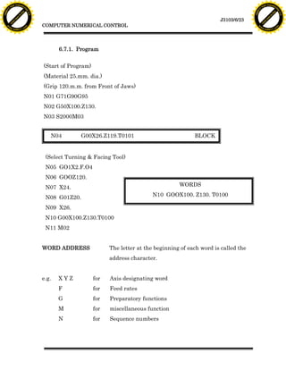
  • 23. F T ra n sf o F T ra n sf o PD rm PD rm Y Y Y Y er er ABB ABB y y bu bu 2.0 2.0 to to re re J3103/6/23 he he k k lic lic COMPUTER NUMERICAL CONTROL C C w om w om w w w. w. A B B Y Y.c A B B Y Y.c 6.7.1. Program (Start of Program) (Material 25.mm. dia.) (Grip 120.m.m. from Front of Jaws) N01 G71G90G95 N02 G50X100.Z130. N03 S2000M03 N04 G00X26.Z119.T0101 BLOCK (Select Turning & Facing Tool) N05 GO1X2.F.O4 N06 GOOZ120. N07 X24. WORDS N08 G01Z20. N10 GOOX100. Z130. T0100 N09 X26. N10 G00X100.Z130.T0100 N11 M02 WORD ADDRESS The letter at the beginning of each word is called the address character. e.g. XYZ for Axis designating word F for Feed rates G for Preparatory functions M for miscellaneous function N for Sequence numbers
  • 24. F T ra n sf o F T ra n sf o PD rm PD rm Y Y Y Y er er ABB ABB y y bu bu 2.0 2.0 to to re re J3103/6/24 he he k k lic lic COMPUTER NUMERICAL CONTROL C C w om w om w w w. w. A B B Y Y.c A B B Y Y.c CNC mills, drills and machining centers are all equipped with cycles to perform drilling, reaming, counter boring, boring and tapping operations. Some others have pocketing cycles, slot cutting cycles, hole pattern cycles etc, all of which are designed to save programming time and effort. CNC lathes usually have cycles to cover drilling, grooving/parting, screw cutting, repetitive cut (automatic roughing) operations and others. Each cycle has its own G code to control the sequence of motions and an accompanying set of words to define the parameters of those motions. These words have addresses such as: R,P,Q,D,E,I,K,H,B etc. 6.7.2. Program Preparation CNC programmes can be prepared manually, where the programmer usually roughs the programme out on paper, then produces it via a keyboard device of the type detailed below, or by assisted preparation in which a computer plays a predominant role -such as when CAD/CAM packages have been installed for design and programming. The programmer must posses knowledge and skills in planning machining sequences, fixturing, cutting data, cutting tools, calculations, as well as being familiar with the machines he is programming. To implement these skills to best effect a programmer should be prepared to observe critically his programs in use and modify them as necessary in order to gain maximum machine utilization. 6.7.3. Operation of program Before a machine can set into automatic motion a program must be checked for errors. A simple typing mistake - an incorrect code, a minus sign instead of a zero, the exclusion of a decimal etc, could cause and expensive
  • 25. F T ra n sf o F T ra n sf o PD rm PD rm Y Y Y Y er er ABB ABB y y bu bu 2.0 2.0 to to re re J3103/6/25 he he k k lic lic COMPUTER NUMERICAL CONTROL C C w om w om w w w. w. A B B Y Y.c A B B Y Y.c machine crash. Anyone who considers their programmes to be without error and not in need of careful and conscientious trialing has an attitude problem and is placing expensive machinery and operators safety at risk. There may be many ways in which a programme can be checked for errors, but a programme can only be proved 100% by running the machine and producing a part. Error checking can be performed in a variety of ways: Verification: Read through the print-out (NOT the handwritten manuscript) carefully - sometimes mistakes can be seen easily. Trialing: This involves the execution of the programme without actually cutting the part and may be carried out in several ways depending on the type of machine, or control, or even the philosophy of the person in charge. Adhere to the later unless you can put up good reasons for alteration. Trialing usually consists of running the machinewith the single block switch active, that is, each block will only be executed by pressing cycle start, in conjunction with the programme being displayed on the screen. Quite often the dry run mode is switched on to hasten Proceedings. 'Dry Run' results in all machine motion being executed at a preset rate, usually in the region of 50% to 80% of the rapid traverse capability of the machine. The actual axis velocity can be overridden from 0% to 100%. The disadvantage of dry running a programme is that feed rates will be masked, and attention must be paid to determining the actual programmed feed rate for each block. This may be displayed on the screen.
  • 26. F T ra n sf o F T ra n sf o PD rm PD rm Y Y Y Y er er ABB ABB y y bu bu 2.0 2.0 to to re re J3103/6/26 he he k k lic lic COMPUTER NUMERICAL CONTROL C C w om w om w w w. w. A B B Y Y.c A B B Y Y.c Every movement the machine makes during programme trialing should be expected and accountable to the programmer, if not, those motions should be checked for viability, and if necessary, a more thorough understanding of the machine operation should be sought. Editing: Wherever errors are found, they should be corrected and rechecked, be it on the machine or at the programming station. Whenever a programme is edited on the machine, a note should be made on the print-out so the master or original programme can also be corrected. A better method is to punch out a programme from the control after successfully producing a component. 6.8. TYPES OF CONTROL SYSTEM There are two basic types of control systems in numerical control: point- to-point and contouring. a. In a point-to-point system, also called positioning, each axis of the machine is driven separately by lead screws and, depending on the type of operation, at different velocities. The machine moves initially at maximum velocity in order to reduce non-productive time, but decelerates as the tool approaches its numerically defined position. Thus, in an operation such as drilling (or punching a hole), the positioning and cutting take place sequentially (Fig. 5.4).
  • 27. F T ra n sf o F T ra n sf o PD rm PD rm Y Y Y Y er er ABB ABB y y bu bu 2.0 2.0 to to re re J3103/6/27 he he k k lic lic COMPUTER NUMERICAL CONTROL C C w om w om w w w. w. A B B Y Y.c A B B Y Y.c After the hole is drilled or punched, the tool retracts upward and moves rapidly to another position, and the operation is repeated. The path followed from one position to another is important in only one respect. It must be chosen to minimize the time of travel, for better efficiency. Point-to-point systems are used mainly in drilling, punching, and straight milling operations. 15 10 45 C.P 15 (0,0) 10 1 2 4 3 45 Incremental (G90) Absolute (G91) Position Coordinate Coordinate Position Coordinate Coordinate (X) (Y) (X) (Y) C.P. -15 15 C.P. -15 15 Point 1 10 -10 Point 1 25 -25 Point 2 55 -10 Point 2 45 0 Point 3 55 -55 Point 3 0 -45 Point 4 10 -55 Point 4 -45 0 Figure 5.4. Point-to point system
  • 28. F T ra n sf o F T ra n sf o PD rm PD rm Y Y Y Y er er ABB ABB y y bu bu 2.0 2.0 to to re re J3103/6/28 he he k k lic lic COMPUTER NUMERICAL CONTROL C C w om w om w w w. w. A B B Y Y.c A B B Y Y.c b. In a contouring system (also known as a continuous path system), the positioning and the operations are both performed along controlled paths but at different velocities. Because the tool acts as it travels along a prescribed path (Fig. 5.5), accurate control and synchronization of velocities and movements are important. The contouring system is typically used on lathes, milling machines, grinders, welding machinery, and machining centres. Cutter Machined radius surface Cutter path Work piece Figure 5.5. Continuous path by a milling cutter 6.9. PROGRAMMING CODES A number of standard codes are used to reduce the amount of programming effort needed to command commonly used machining operations, instructions and conditions. These are commonly known as: G codes – call up machining commands M codes – call up machine control activities T codes – call up tool selection F codes – call up feed rates S codes – call
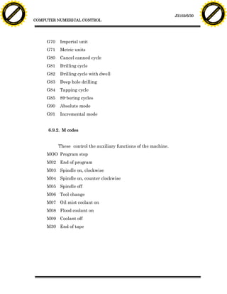
  • 29. F T ra n sf o F T ra n sf o PD rm PD rm Y Y Y Y er er ABB ABB y y bu bu 2.0 2.0 to to re re J3103/6/29 he he k k lic lic COMPUTER NUMERICAL CONTROL C C w om w om w w w. w. A B B Y Y.c A B B Y Y.c - modal codes remain active after being entered, unless they are cancelled by another G code; and - non-modal codes are only active in the programme block in which they appear. 6.9.1. G codes (preparatory codes) The majority of manufacturers follow the same practice in designation of codes, but their detailed implementation mav differ. Sample G codes GOO Rapid movement for position GOI Linear interpolation used for straight-line feed G02 Circular interpolation, clockwise G03 Circular interpolartion, counterclockwise G04 Dwell, a programmed stop to the tool movement G17 Circular interpolation xy plane G18 Circular interpolation xz plane G19 Circular interpolation yz plane G20 Inch units G21 Millimetre units G28 Return to home position G29 Return from home position G31 Reverses programmed direction of x axis G32 Reverses programmed direction of y axis G41 Tool radius compensation left G42 Tool radius compensation right G43 Tool length compensation-positive direction G44 Tool length compensation-negative direction
  • 30. F T ra n sf o F T ra n sf o PD rm PD rm Y Y Y Y er er ABB ABB y y bu bu 2.0 2.0 to to re re J3103/6/30 he he k k lic lic COMPUTER NUMERICAL CONTROL C C w om w om w w w. w. A B B Y Y.c A B B Y Y.c G70 Imperial unit G71 Metric units G80 Cancel canned cycle G81 Drilling cycle G82 Drilling cycle with dwell G83 Deep hole drilling G84 Tapping cycle G85 89-boring cycles G90 Absolute mode G91 Incremental mode 6.9.2. M codes These control the auxiliary functions of the machine. MOO Program stop M02 End of program M03 Spindle on, clockwise M04 Spindle on, counter clockwise M05 Spindle off M06 Tool change M07 Oil mist coolant on M08 Flood coolant on M09 Coolant off M30 End of tape
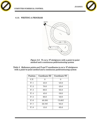
  • 31. F T ra n sf o F T ra n sf o PD rm PD rm Y Y Y Y er er ABB ABB y y bu bu 2.0 2.0 to to re re J3103/6/31 he he k k lic lic COMPUTER NUMERICAL CONTROL C C w om w om w w w. w. A B B Y Y.c A B B Y Y.c 6.10. WRITING A PROGRAM Figure 5.6. To cut a ‘S’-slot/groove with a point-to-point method and a continuous path/contouring system Table 5. Reference points and X and Y coordinates to cut a ‘S’-slot/groove with a point-to-point method and a continuous path/contouring system Position Coordinate (X) Coordinate (Y) C.P. 0 0 P. 1 45.0 -25.0 P. 2 70.0 -25.0 P. 3 60.0 -65.0 P. 4 45.0 -50.0 P. 5 60.0 -50.0 P. 6 49.393 -75.607 P. 7 38.787 -65.0 P. 8 15.0 -65.0
  • 32. F T ra n sf o F T ra n sf o PD rm PD rm Y Y Y Y er er ABB ABB y y bu bu 2.0 2.0 to to re re J3103/6/32 he he k k lic lic COMPUTER NUMERICAL CONTROL C C w om w om w w w. w. A B B Y Y.c A B B Y Y.c To machine the above component (as in Fig.5.6), below is the programme that can be followed; N10 G71 G90 S1500 T1 N130 G00 M00 N20 G00 X0 Y0 N140 G00 X0 Y0 N30 G00 X70.0 Y-25.0 Z10.0 N40 G01 Z-5.0 F250 N50 G03 I-25.0 J0 N60 X45.0 Y-50.0 N70 G01 X60.0 Y -50.0 N80 G02 I0 J-15.0 N90 X49.393 Y-75.607 N100 G01 X38.787 Y-65.0 N110 X15.0 Y-65.0 N120 Z10.0 Description of The Above Programme NXX – block number Block No. 10 – set machine to use metric unit, incremental coordinate, spindle speed 1500 rpm, choose tool no. 1. Block No. 20 – rapid movement to centre point (C.P). Block No. 30 - rapid movement to point 1 (P. 1), cutting tool distance is 5.0 mm from the surface of the work piece. Block No. 40 – cutting tool cuts 10.00 mm deep, feed 250 mm/min Block No. 50 – circular interpolation, counter clockwise, radius 25.0 mm
  • 33. F T ra n sf o F T ra n sf o PD rm PD rm Y Y Y Y er er ABB ABB y y bu bu 2.0 2.0 to to re re J3103/6/33 he he k k lic lic COMPUTER NUMERICAL CONTROL C C w om w om w w w. w. A B B Y Y.c A B B Y Y.c Block No. 60 – tool ends interpolation cutting at P. 4 Block No. 70 – linear interpolation until P. 5 Block No. 80 - circular interpolation, clockwise, radius 15.0 mm Block No. 90 - tool ends interpolation cutting at P. 6 Block No. 100 - linear interpolation until P. 7 Block No. 110 - linear interpolation until P. 8 Block No. 120 – tool rises up 10.0 mm Block No. 130 – program stops Block No. 140 - rapid return to centre point (C.P). 6.11. ADVANTAGES OF COMPUTER NUMERICAL CONTROL i. The component programming tape and the tape reader are used once only when the programme is copied into the computer memory, not only this practice wills same time but it will also reduce errors. ii. The programming tape can be edited on the shop floor, when the machine is placed/located. Editing, correction and optimising; such as machine tool operations, spindle speeds and speeds; are usually done in the test run of the tape. iii. Computer numerical control can easily changes into metric system if the programme is in the imperial units. iv. It is widely used in industry. It is easily adaptable in a computerised industry system. v. Increased flexibility – the machine can produce a specific part, followed by other parts with different shapes, and at reduces cost. vi. Greater accuracy – computers have a higher sampling rate and faster operation.
  • 34. F T ra n sf o F T ra n sf o PD rm PD rm Y Y Y Y er er ABB ABB y y bu bu 2.0 2.0 to to re re J3103/6/34 he he k k lic lic COMPUTER NUMERICAL CONTROL C C w om w om w w w. w. A B B Y Y.c A B B Y Y.c vii. More versatility – editing and debugging programmes, reprogramming, and plotting and printing part shape are simpler. viii. Programmes are stored on the machine ready for use. ix. Programmes and data can be modified on the machine.
  • 35. F T ra n sf o F T ra n sf o PD rm PD rm Y Y Y Y er er ABB ABB y y bu bu 2.0 2.0 to to re re J3103/6/35 he he k k lic lic COMPUTER NUMERICAL CONTROL C C w om w om w w w. w. A B B Y Y.c A B B Y Y.c ACTIVITY 6 6.1. Briefly state four (4) advantages of numerical control system. 6.2. You are given a drawing of a component. List down the steps you would take to operate a NC machine in order produce the component. 6.3. Write a short paragraph on three (3) basic components of a numerical control system.
  • 36. F T ra n sf o F T ra n sf o PD rm PD rm Y Y Y Y er er ABB ABB y y bu bu 2.0 2.0 to to re re J3103/6/36 he he k k lic lic COMPUTER NUMERICAL CONTROL C C w om w om w w w. w. A B B Y Y.c A B B Y Y.c FEEDBACK ON ACTIVITY 6 6.1. The advantages of numerical control system are: i. The component programming tape and the tape reader are used once only when the programme is copied into the computer memory, not only this practice wills same time but it will also reduce errors. ii. The programming tape can be edited on the shop floor, when the machine is placed/located. Editing, correction and optimising; such as machine tool operations, spindle speeds and speeds; are usually done in the test run of the tape. iii. Computer numerical control can easily changes into metric system if the program is in the imperial units. iv. It is widely used in industry. It is easily adaptable in a computerised industry system. v. Increased flexibility – the machine can produce a specific part, followed by other parts with different shapes, and at reduces cost. vi. Greater accuracy – computers have a higher sampling rate and faster operation. vii. More versatility – editing and debugging programs, reprogramming, and plotting and printing part shape are simpler. viii. Programs are stored on the machine ready for use. ix. Programs and data can be modified on the machine.
  • 37. F T ra n sf o F T ra n sf o PD rm PD rm Y Y Y Y er er ABB ABB y y bu bu 2.0 2.0 to to re re J3103/6/37 he he k k lic lic COMPUTER NUMERICAL CONTROL C C w om w om w w w. w. A B B Y Y.c A B B Y Y.c 6.2. Job Planning 1. Sketch the part. Add incremental or absolute dimensions. 2. Ascertain fixturing. Select fixtures which have minimal projections above the part. 3. Identify a set-up point. Locate the set-up point near: 1. A corner of the part 2. A spot above the fixture Consider space requirements for: 1. Part loading and unloading 2. Tool change. 4. Plan operation sequence Mark sequence pattern of sketch. Test program data for accuracy. 5. Record necessary data for each movement of the table and tool on the program sheet. 6. Record instructions for Identify, specific: the machine operator. 1. Tools needed. 2. Speed and feed data 3. Tool change points 4. Console switch setting 6.3.(a) Machine Tool - a device designed to cut away surplus material and leave a component of the required shape and size. It holds the work piece, cutting tool and moves the tool and work piece relative to one another precisely enough to achieve accuracy of size and surface finish. It can also alter the spindle speed and feed rates, tool changing, supply of coolant etc.
  • 38. F T ra n sf o F T ra n sf o PD rm PD rm Y Y Y Y er er ABB ABB y y bu bu 2.0 2.0 to to re re J3103/6/38 he he k k lic lic COMPUTER NUMERICAL CONTROL C C w om w om w w w. w. A B B Y Y.c A B B Y Y.c (b) The Control Unit - reads, decodes the part programme and provides the decoded instructions to the control loops of the machine axes of motion, and to control the machine tool operations. There are three main parts of the control unit namely, the Control Panel, the Tape Reader and the Processors (c) Control system - there are two types of control systems used on NC machines - the point-to-point system and the continuous-path system. The point-to-point systems operates only in straight lines, which are suitable for positioning moves on a drilling machine or limited use on a lathe or milling machine, where at best 45% cuts are possible with two axes running continuous path controls allow angular path and radius motion because the control interpolator has the ability to move the axis drive motors at varying velocities. The point-to-point controls were NC controls, while the continuous path controls could be NC or CNC controls.
  • 39. F T ra n sf o F T ra n sf o PD rm PD rm Y Y Y Y er er ABB ABB y y bu bu 2.0 2.0 to to re re J3103/6/39 he he k k lic lic COMPUTER NUMERICAL CONTROL C C w om w om w w w. w. A B B Y Y.c A B B Y Y.c SELF-ASSESSMENT 6 1. Numerical control machine can be done in absolute coordinate (G90) and incremental coordinates (G91). What is the difference between the two coordinates. 2. By using G90 and G 91 coordinates write a program to cut a component in is the .below figure. 30 J20 70 35 20 60
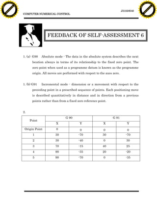
  • 40. F T ra n sf o F T ra n sf o PD rm PD rm Y Y Y Y er er ABB ABB y y bu bu 2.0 2.0 to to re re J3103/6/40 he he k k lic lic COMPUTER NUMERICAL CONTROL C C w om w om w w w. w. A B B Y Y.c A B B Y Y.c FEEDBACK OF SELF-ASSESSMENT 6 1. (a) G90 Absolute mode - The data in the absolute system describes the next location always in terms of its relationship to the fixed zero point. The zero point when used as a programme datum is known as the programme origin. All moves are performed with respect to the axes zero. 1. (b) G91 Incremental mode - dimension or a movement with respect to the preceding point in a prescribed sequence of points. Each positioning move is described quantitatively in distance and in direction from a previous points rather than from a fixed zero reference point. 2. G 90 G 91 Point X Y X Y Origin Point 0 0 0 0 1 30 -70 30 -70 2 30 -40 0 30 3 70 -15 40 25 4 90 -35 20 -20 5 90 -70 0 -35
  • 41. F T ra n sf o F T ra n sf o PD rm PD rm Y Y Y Y er er ABB ABB y y bu bu 2.0 2.0 to to re re he he k k lic lic C C w om w om w w w. w. A B B Y Y.c A B B Y Y.c