SlideShare a Scribd company logo
WIRELESS LED NOTICE BOARD
Department of Electronics and Communication Engineering, TIST, CUSAT
1
WIRELESS LED NOTICE BOARD
Rohith Raju
Suraj S Prabhu
Prathik Venugopal
Departmentof ElectronicsandCommunication,MinorProject
WIRELESS LED NOTICE BOARD
Department of Electronics and Communication Engineering, TIST, CUSAT
2
CHAPTER .1
INTRODUCTION
In recent years, countless articles have focused on new display technologies. Typical
topics have covered: The explosion of TFT colour LCD panels with ever –increasing size
into laptops and flat-screen monitor; PDP (plasma display panels) for high-definition TV-
CRT replacement; polymer LED (PLED) or organic LED (OLED) displays for the small
colour displays in games, cell phones, and PDAs. This overview covers the origin of LEDs,
their traditional applications, and how improvements in the Technology have stimulated
new applications. A number of displays can be interfaced with control logic to display
numbers, letters, special characters and even graphics. This project will be based on the
light emitting diode (LED). LED displays come in three basic configurations, numeric
(numbers), alphanumeric (number and letters), and dot matrix forms. Numeric display
consists of 7-LED segment each LED segment is given a letter designation. The 7-
segment led displays are most frequently used to generate numbers (0-9), but they also
can be used to display hexadecimal (0-9,A,B,C,D,E,and F).The 14-segment ,16 segment
and special 4 by 7 dot matrix displays are alphanumeric, while the 5 by 7 dot matrix display
is both alphanumeric and graphic. You can display unique characters and simple graphics
WIRELESS LED NOTICE BOARD
Department of Electronics and Communication Engineering, TIST, CUSAT
3
1.1 AIM OF PROJECT
This project demonstrates the design and construction of a digital display board with
moving message display, digital clock and date; showing also how the message can be
altered in order to enter a new set of data.
1.2 METHODOLOGY
The implementation of the project is based around the PIC 16F877A microcontroller.
The displayed message can be changed by programming a new message into the
microcontroller connected to a host computer.
WIRELESS LED NOTICE BOARD
Department of Electronics and Communication Engineering, TIST, CUSAT
4
LITERATURE REVIEW
WIRELESS LED NOTICE BOARD
Department of Electronics and Communication Engineering, TIST, CUSAT
5
CHAPTER .2
LITERATURE REVIEW
The early 1980’s marked the beginning of the technology resolution in message display
industry. The varieties of technologies that emerged over time include: cathode ray tube,
liquid crystal panels, plasma displays, and LED displays. The LED display (light emitting
diode) was one of the new technologies. LED technology has indeed made a major impact
in many markets. For example; Advertising, transportation, employee communication,
and now in multi-million naira outdoor sport arenas. A digital message display board is an
electronic screen on which patterns of alpha-numeric characters known as information is
shown. LED displays are the most common and it is also relatively cheaper than other
forms of display when compared in terms of cost of production and maintenance. LED
displays are those designed with light emitting diodes.LED display can provide you with
the ability to capture and display all types of data to include news feeds, flight information,
factory automation, train information and even real time news feeds from the internet.
However , the LED displays come in two forms : the fixed character type in which the
characters composing the message are permanently arranged with LEDS on the screen
and variable character type in which new messages can be inputted as many times as
wanted. The fixed types have a major setback in that only one message type would always
be displayed. To display an entirely new message, the LED must be rearranged which
raises concern on the cost and time needed to carry out such a task thus limiting its
practical usefulness in a dynamic society like ours. Therefore in order for such to find
practical uses, the message must be alterable as many times as wanted without touching
the LEDS. This requirement gave rise to the development of the variable LED display,
popularly known as the moving message display. These messages are scrolled just in a
single line. In this project, the message display is realised by the use of a microcontroller.
The messages are stored in the internal memory of the microcontroller in form of data
which are sent to the display board in a 7 bit pattern. These data are also used to turn
on/off LEDS on the LED board.
WIRELESS LED NOTICE BOARD
Department of Electronics and Communication Engineering, TIST, CUSAT
6
OBJECTIVE
WIRELESS LED NOTICE BOARD
Department of Electronics and Communication Engineering, TIST, CUSAT
7
CHAPTER .3
OBJECTIVE OF THE PROJECT
PROBLEM DEFINITION
The main of the project is to improve message scrolling in a display unit by cascading
various LED display sections and increasing its influence over wide area using XBEE
module and PIC Microcontroller Unit. The project demonstrates the design and
construction of a digital display that maximizes the cascading of several 5x7 dot led matrix
. The use of Vero board or bread board is not a good option for this project because using
a Vero board will require the use of a lot of wiring which will make the construction messy
and untidy. Apart from making the work untidy, it will make the construction of the display
unit very difficult. So in order to overcome this problem 5x7 LED display is used that is
operated using PIC microcontroller and driver 74HC595.
The construction mainly consists of transmitter section and a
receiver section. The transmitter has a host system that is used for typing data needed to
be displayed .The data is transferred in the form of packet of bits through a serial port to
a level shifter MAX232 that reduces the voltage level to TTL/CMOS level which is then
received by a XBEE module that acts as a antenna of the transmitter section.
This transferred data is then received by another XBEE module which
then sends the data to PIC microcontroller for parallel transmission of data. This parallel
data at various points are received by LED driver 74HC595 that drives the led display unit
thus displaying scrolling of message/data. The use of XBee technology means that
communication is wireless and power consumption is low .
This project has a very wide scope in industries, hospitals,
Educational institutions and transport areas where an very important message or
announcement is to be made on large basis.
WIRELESS LED NOTICE BOARD
Department of Electronics and Communication Engineering, TIST, CUSAT
8
PROJECT ANLYSIS AND DESIGN
WIRELESS LED NOTICE BOARD
Department of Electronics and Communication Engineering, TIST, CUSAT
9
CHAPTER .4
PROJECT ANALYSIS AND DESIGN
4.1. BLOCK DIAGRAM
FIG 1.Block Diagram
WIRELESS LED NOTICE BOARD
Department of Electronics and Communication Engineering, TIST, CUSAT
10
4.2 BLOCK DIAGRAM EXPLANATION
1. HOST SYSTEM:-
The host system used here can be any PC system with an inbuilt USART
controller the message to be displayed is typed in this system.
2. RS232:-
RS 232 is a serial port standard that is used for serial transmission of
data packets from the host system to MAX 232.The voltage level
provided by this port is +3v to +15v.the port used here is a 9 pin DIP.
3. MAX232:-
MAX 232 here works as a voltage level shifter that converts the pc
level voltage (ie .+3v to +15v) to TTL/CMOS level(0v to +5v) so that
the data transferred becomescompatible XBEE module whose mini
ref. supply voltage is 3.3V.MAX232 need power supply of +5v for its
operation which is provided by an extern. Power supply.
4. XBEE PRO:-
XBEE is wireless communication module that can be used both as
transmitter as well as receiver.At the transmitter sectionit acts like an
antenna which is used for transmitting data which is received by
another XBEE module at the receiver section.The data transmitted
and received at the XBEE is in digital format. It requires supply of
3.3V for its operation.
WIRELESS LED NOTICE BOARD
Department of Electronics and Communication Engineering, TIST, CUSAT
11
5. PIC16F877A:-
It is a microcontrollerthat receives data serially and can transmitte
data either in serial format/in parallel format. In this context the con
roller is programmed to accept data serially and transmitte data in
parallel format. The PIC used here of 40 pin DIP and has 5 i/o ports.
5. LED DRIVER(74HC595):-
LED driver 74hc595 is a driver used or driving 5x7 LED dot matrix.
The packets of data form PIC serially reaches the driver and then it
is fed to LED display.
WIRELESS LED NOTICE BOARD
Department of Electronics and Communication Engineering, TIST, CUSAT
12
4.3 CIRCUIT DIAGRAM
TRANSMITTER SECTION:-
Fig2. Circuit Diagram of The Transmitter Section
R3
10K
C5
CAP NP
0
D1
LED
R5
180
Q1
0
VCC
3.3V
XBee
3.3V
db 9 serial port
9013
C1+
1
C1-
3
C2+
4
C2-
5
V+
2
V-
6
R1OUT
12
R2OUT
9
T1IN
11
T2IN
10
R1IN
13
R2IN
8
T1OUT
14
T2OUT
7
U2
MAX232
C1
CAP
C2
CAP
C3
CAP
C4
CAP
0
VCC
16
15
Dout
1A
2A
3A
4A
5A
6A
7A
8A
9A
J1A
CONN ASY DSUB 9-R/9-R
pwm
reset
Din
Vcc
VCC
VCC
R2
10K
VCC
3.3V+5V
+5V
R1
10K
R4
10K
WIRELESS LED NOTICE BOARD
Department of Electronics and Communication Engineering, TIST, CUSAT
13
RECEIVER SECTION:-
Fig 3.Circuit Diagram Of The ReceiverSection
WIRELESS LED NOTICE BOARD
Department of Electronics and Communication Engineering, TIST, CUSAT
14
CIRCUIT DIAGRAM OF 5v SUPPLY (FOR MAX232):
Fig .4 5v Power Supply Design
WIRELESS LED NOTICE BOARD
Department of Electronics and Communication Engineering, TIST, CUSAT
15
4.4 EXPLANATION FOR CHARACTER FORMATION
Fig. 5. 5x7LED MATRIX
The LED dot-matrix display :
The LED dot-matrix display is basically an arrangement of LEDs in a row and column formation
like the elements of a mathematical matrix, hence its name. The LEDs therefore form the dots
which characterizes its name. This pattern arrangement of LEDs is similar to the pixel dots of a
typical cathode-ray tube. Thus, any character can be formed by lighting the appropriate dot on the
display. These appropriate dots for the character are known as its display pattern. The construction
of a typical dot-matrix display is achieved by connecting LEDs between horizontal and vertical
grid lines. These grid lines are actually connection paths. This connection scheme therefore implies
that each LED of the matrix has one terminal on a row path and the other on a column path and as
a result, this connection scheme has two forms, one in which all LED cathodes are connected on
the column paths and the anodes on the row paths or vice-versa. Also,
WIRELESS LED NOTICE BOARD
Department of Electronics and Communication Engineering, TIST, CUSAT
16
dot –matrix displays are popularly referred to by their matrix size, that is, the number of LEDs on
a row and on a column. The most popular type is the 5x7 matrix, that is, this display has 5 LED
columns with 7 LEDs on each column and 7 LED rows with 5 LEDs on each row.
The Main Controller(PIC 16F877A):-
The next block and probably the most important is the main controller. This is the unit responsible
for the co-ordination and complete operation of the whole system. It fetches the character patterns
from the memory unit and outputs them on the display at the same time sending the appropriate
logic to the column selector unit. All these operations must be done in a fraction of a second
therefore requiring the use of micro processor based controller. Employed for this design is a
microcontroller- the PIC16F877A microcontroller from MICROCHIP INC; a RISC (reduced
instruction set) processor. The microcontroller in question was chosen as result of apart from
fulfilling the basic requirements such as number of ports, speed, etc. Its simplicity in usage and
connection, direct LED drive capability of the ports and most importantly, it’s really reduced
instruction set; just 35 instructions. Each character to be displayed has a sequence which is used to
form the character in question on the display. This lighting sequence is known as the character
pattern. One basic character pattern employed in this design is the “UPPER CASE”. Other
character patterns such as lower case, bold, italics, etc can also be added. These patterns must be
stored in a non-volatile kind of memory since they represent constant data. They represent the form
each character of the message will assume on the display. The message to be displayed must also
be stored on a non-volatile memory since the message must always be available even after a power
outage. Also the actual message represent a large amount of data since information is what’s in
question, therefore a fairly large memory space is needed. The microcontroller PIC16F877 is
8Kbyte in memory capacity. With a 2Kbyte of memory space, approximately, a page of characters
can be entered. In this design, both the character patterns and the message codes are stored in the
microcontroller for faster access by the controller and space and wire connection considerations as
compared to when using separate memories for the two fields.
WIRELESS LED NOTICE BOARD
Department of Electronics and Communication Engineering, TIST, CUSAT
17
The Column SelectorUnit
The last block is the column selector unit. The controller forms the characters on the dot-matrix
display by activating each column sequentially and at the same time sending the appropriate data
for each column on the rows. Therefore this unit is for proper selection of appropriate column. This
selection is done at a very fast rate from one end of the display to the other. Usually, shift register
counter are used in the implementation of this unit. The output bits of the register counter must
equal the total number of columns. In the case of the 5 x 7 matrix display, a 5-bit shift register
counter is needed. The shifting of the register is fully controlled by the main controller unit which
sends the appropriate control logic.
WIRELESS LED NOTICE BOARD
Department of Electronics and Communication Engineering, TIST, CUSAT
18
LED WORKING THEORY:
The LED matrix used in this experiment is of size 5×7. We will learn how to display still
characters in a standard 5×7 pixel format. The figure below shows which LEDs are to be
turned on to display the English alphabet ‘A’. The 7 rows and 5 columns are controlled
through the microcontroller pins. Now, lets see in detail how it works.
Suppose, we want to display the alphabet A. We will first select the column C1 (which
means C1 is pulled low in this case), and deselect other columns by blocking their ground
paths (one way of doing that is by pulling C2 through C5 pins to logic high). Now, the first
column is active, and you need to turn on the LEDs in the rows R2 through R7 of this
column, which can be done by applying forward bias voltages to these rows. Next, select
the column C2 (and deselect all other columns), and apply forward bias to R1 and R5,
and so on. Therefore, by scanning across the column quickly (> 100 times per second),
and turning on the respective LEDs in each row of that column, the persistence of vision
comes in to play, and we perceive the display image as still.
Fig 5.Logic Levels For Displaying Alphabet ‘A’.
The table ABOVE gives the logic levels to be applied to R1 through R7 for each of the
columns in order to display the alphabet ‘A’.
WIRELESS LED NOTICE BOARD
Department of Electronics and Communication Engineering, TIST, CUSAT
19
4.5 COMPONENTS DESCRIPTION
RS 232
Fig.6.rs232
RS-232 is defined as the“ Interface between data terminal equipment and data
communication equipment using serial binary data exchange.” This definition defines data
terminal equipment (DTE) as the computer, while data communications equipment (DCE)
is the modem. A modem cable has pin-to-pin connections, and is designed to connect a
DTE device to a DCE device. Information being transferred between data processing
equipment and peripherals is in the form of digital data which is transmitted in a serial
mode. Serial transmission involves the sending of data one bit at a time, over a single
communications line. RS-232 cables are commonly available with either 4, 9 or 25-pin
wiring.
FEATURES:
 TRANSMITTED SIGNAL
VOLTAGE LEVELS:
Binary 0: +5 to +15 Vdc
(called a “space” or “on”)
Binary 1: -5 to -15 Vdc
(called a “mark” or “off”)
 RECEIVED SIGNAL
WIRELESS LED NOTICE BOARD
Department of Electronics and Communication Engineering, TIST, CUSAT
20
VOLTAGE LEVELS:
Binary 0: +3 to +13 Vdc
Binary 1: -3 to -13 Vdc
 DATA FORMAT:
Start bit: Binary 0
Data: 5, 6, 7 or 8 bits
Parity: Odd, even, mark or space
(not used with 8-bit data)
Stop bit: Binary 1,
MAX 232
Fig 7.MAX232
The MAX232 is an integrated circuit that converts signals from an RS-232 serial port to
signals suitable for use in TTL compatible digital logic circuits. The MAX232 is a dual
driver/receiver and typically converts the RX, TX, CTS and RTS signals. The drivers
provide RS-232 voltage level outputs (approx. ± 7.5 V) from a single + 5 V supply via on-
chip charge pumps and external capacitors. This makes it useful for implementing RS-
232 in devices that otherwise do not need any voltages outside the 0 V to + 5 V range,
as power supply design does not need to be made more complicated just for driving the
RS-232 in this case.
WIRELESS LED NOTICE BOARD
Department of Electronics and Communication Engineering, TIST, CUSAT
21
The receivers reduce RS-232 inputs (which may be as high as ± 25 V), to standard
5 V TTL levels. These receivers have a typical threshold of 1.3 V, and a
typical hysteresis of 0.5 V.
When a MAX232 IC receives a TTL level to convert, it changes a TTL Logic 0 to between
+3 and +15 V, and changes TTL Logic 1 to between -3 to -15 V, and vice versa for
converting from RS232 to TTL.
FEATURES:
_ Operates From a Single 5-V Power Supply
With 1.0-_F Charge-Pump Capacitors
_ Operates Up To 120 kbit/s
_ Two Drivers and Two Receivers
_ ±30-V Input Levels
_ Low Supply Current . . . 8 mA Typical
XBEE PRO
Fig 8.XBEE module
XBee multipoint RF modules are ideal for applications requiring low latency and
predictable communication timing. Providing quick, robust communication in point-to-
point, peer-to-peer, and multipoint/star configurations, XBee multipoint products enable
robust end-point connectivity with ease. Whether deployed as a pure cable replacement
for simple serial communication, or as part of a more complex hub-and-spoke network of
sensors,
WIRELESS LED NOTICE BOARD
Department of Electronics and Communication Engineering, TIST, CUSAT
22
XBee multipoint RF modules maximize wireless performance and ease of development.
It support the unique needs of low-cost, low-power wireless sensor networks. The
modules require minimal power and provide reliable delivery of data between devices.
The modules operate within the ISM 2.4 GHz frequency band and are pin-for-pin
compatible with each other.
Features/Benefits
• 802.15.4/Multipoint network topologies
• 2.4 GHz for worldwide deployment
• 900 MHz for long-range deployment
• Common XBee footprint for a variety of RF modules
• Low-power sleep modes
• Multiple antenna options
KEY FEATURES
WIRELESS LED NOTICE BOARD
Department of Electronics and Communication Engineering, TIST, CUSAT
23
PIC 16F877A
Fig.9 pic 16f877a
The PIC16F877A CMOS FLASH-based 8-bit microcontroller is upward compatible with
the PIC16C5x, PIC12Cxxx and PIC16C7x devices. It features 200 ns instruction
execution, 256 bytes of EEPROM data memory, self programming, an ICD, 2
Comparators, 8 channels of 10-bit Analog-to-Digital (A/D) converter, 2
capture/compare/PWM functions, a synchronous serial port that can be configured as
either 3-wire SPI or 2-wire I2C bus, a USART, and a Parallel Slave Port.
SpecialMicrocontroller Features:
 Flash Memory: 14.3 Kbytes (8192 words)
 Data SRAM: 368 bytes
 Data EEPROM: 256 bytes
 Self-reprogrammable under software control
 In-Circuit Serial Programming via two pins (5V)
 Watchdog Timer with on-chip RC oscillator
 Programmable code protection
 Power-saving Sleep mode
 Selectable oscillator options
 In-Circuit Debug via two pins
Peripheral Features
 33 I/O pins; 5 I/O ports
WIRELESS LED NOTICE BOARD
Department of Electronics and Communication Engineering, TIST, CUSAT
24
 Timer0: 8-bit timer/counter with 8-bit prescaler
 Timer1: 16-bit timer/counter with prescaler
 Timer2: 8-bit timer/counter with 8-bit period register, prescaler and postscaler
74HC595
Fig 10.74HC595 driver
The 74HC595; are high speed Si-gate CMOS devices and are pin compatible with Low-
power Schottky TTL (LSTTL). They are specified in compliance with JEDEC standard No.
7A.
The 74HC595; is 8-stage serial shift registers with a storage register and 3-state outputs.
The registers have separate clocks.
Data is shifted on the positive-going transitions of the shift register clock input (SHCP).
The data in each register is transferred to the storage register on a positive-going
transition of the storage register clock input (STCP). If both clocks are connected together,
the shift register will always be one clock pulse ahead of the storage register. The shift
register has a serial input (DS) and a serial standard output (Q7S) for cascading. It is also
provided with asynchronous reset (active LOW) for all 8 shift register stages. The storage
register has 8 parallel 3-state bus driver outputs. Data
in the storage register appears at the output whenever the output enable input (OE) is
LOW.
WIRELESS LED NOTICE BOARD
Department of Electronics and Communication Engineering, TIST, CUSAT
25
FEATURES:
-bit serial input
-bit serial or parallel output
-state outputs
with direct clear
5X7 LED DOT MATRIX:
Fig 11.5x7 LED Display
The LTP-2X57A series are 2.0 inch (50.80mm) matrix height 5 7 dot matrix displays.
The LTP-2057/2157A series are single colour displays. The green, yellow, red orange
and AlGaAs red displays have grey face and white dots. The yellow and red orange
series devices utilize LED chips which are made from GaAsP on a transparent GaP
substrate.
FEATURES:
• 2.0 inch (50.80mm)matrix height.
• Low power requirement.
• Single plane, wide viewing angle.
• Solid state reliability.
• 5X7 array with X-Y select
WIRELESS LED NOTICE BOARD
Department of Electronics and Communication Engineering, TIST, CUSAT
26
• Stackable horizontally.
• Choices of two matrix orientation
• Cathode row or cathode column.
• Easy mounting on P.C. board.
• Categorized for luminous intensity.
• Single colour displays have the choices of four
• colours-green/yellow/red orange/AlGaAs red.
WIRELESS LED NOTICE BOARD
Department of Electronics and Communication Engineering, TIST, CUSAT
27
PROJECT IMPLEMENTATION
WIRELESS LED NOTICE BOARD
Department of Electronics and Communication Engineering, TIST, CUSAT
28
CHAPTER .5
PROJECT IMPLEMENTATION
5.1 EXPRESS PCB
TRANSMITTERTOP LAYER:
Fig .12. Transmitter top layer
WIRELESS LED NOTICE BOARD
Department of Electronics and Communication Engineering, TIST, CUSAT
29
RECEIVER TOP LAYER:
Fig .13 Receivertop layer
Express PCB is easy to learn. Design 2 or 4 layers boards using the express PCB
program is very simple. Start by inserting the component footprints ,then drag them into
position. Next connect the pins by drawing the traces .Begin the layout by adding the
components. Select the parts from the component Manager dialog box. Drag each
component to the desired location on your PCB board. The Snap to grid feature makes
it easy to neatly align the parts.
WIRELESS LED NOTICE BOARD
Department of Electronics and Communication Engineering, TIST, CUSAT
30
PCB FABRICATION:
Printed circuit board (PCB)provides a method to connect circuits and devices
together. In addition to electrical connections, PCB provides a mechanical
structure to hold the circuits and components together. The PCB is said to be
"printed" because its conductive area is usually generated be means of a printing like
process; artwork preparation, film development, photo-chemical etching, silk screen
printing and surface finishing. Common thickness of rigid PCB is 1.6 mm, in some cases
where space is critical, 0.8 mm thick laminate is a popular choice .Depending on the
number of layers of copper clad and process, 3 basic types of PCB are listed below in
ascending order of interconnection wiring and component density.
1. Single sided PCB: conductors on only one surface of a dielectric base.
2. Double sided PCB: conductors on both sides of a dielectric base; usually
interconnected the two layers with plated-through-holes (PTHs).
3. Multi-layer: conductors on 3 or more layers separated by dielectric material and
interconnected by PT.
STEPS:
 PATTERNING (ETCHING):
The vast majority of printed circuit boards are made by bonding a layer of
copper over the entire substrate, sometimes on both sides, (creating a "blank PCB")
then removing unwanted copper after applying a temporary mask (e.g. by etching),
leaving only the desired copper traces. .
 DRILLING:
Holes, or vias, through a PCB are typically drilled with tiny drill bits made of solid
tungsten carbide. The drilling is performed by automated drilling machines with placement
controlled by a drill tape or drill file. These computer-generated files are also
WIRELESS LED NOTICE BOARD
Department of Electronics and Communication Engineering, TIST, CUSAT
31
called numerically controlled drill (NCD) files or "Excellon files". The drill file describes the
location and size of each drilled hole. When very small vias are required, drilling with
mechanical bits is costly because of high rates of wear and breakage. In this case, the
vias may be evaporated by lasers. Laser-drilled vias typically have an inferior surface
finish inside the hole. These holes are called micro vias. It is also possible with controlled-
depth drilling, laser drilling, or by pre-drilling the individual sheets of the PCB before
lamination, to produce holes that connect only some of the copper layers, rather than
passing through the entire board. These holes are called blind vias when they connect an
internal copper layer to an outer layer, or Buried vias when they connect two or more
internal copper layers and no outer layers. The walls of the holes, for boards with 2 or
more layers, are plated with copper to form plated-through holes that electrically connect
the conducting layers of the PCB. For multilayer boards, those with 4 layers or more,
drilling typically produces a mear comprised of the bonding agent in the laminate system.
Before the holes can be plated through, this smear must be removed by a chemical de-
smear process, or by plasma-etch.
 EXPOSEDCONDUCTORPLATING AND COATING:
The places to which components will be mounted are typically plated because
bare copper oxidizes quickly, and therefore is not readily solderable. Traditionally, any
exposed copper was plated with solder. This solder was a tin-lead alloy, however new
solder compounds are now used to achieve compliance with the RoHS directive in the
EU, which restricts the use of lead. Other platings used are OSP (organic surface
protectant), immersion silver, immersion tin, electro less nickel with immersion gold
coating (ENIG), and direct gold. Edge connectors, placed along one edge of some
boards, are often gold plated.
 SOLDERING:
Soldering is a process in which two or more metal items are joined together
by melting and flowing through a filler metal into the joint, the filler metal having a relatively
low melting point. Soft soldering is characterized by the melting point of the
WIRELESS LED NOTICE BOARD
Department of Electronics and Communication Engineering, TIST, CUSAT
32
filler metal, which is below 400°C. The filler metal used in the process is called solder. In
a soldering process, heat is applied to the parts to be joined, causing the solder to melt
and be drawn into the joint by capillary action and to bond to the materials to be joined
by wetting action. After the metal cools, the resulting joints are not as strong as the base
metal, but have adequate strength, electrical conductivity, and water-tightness for many
uses
5.2.PCB LAYOUT
TRANSMITTER SECTION:
Fig 14.PCB layout of transmitter section
WIRELESS LED NOTICE BOARD
Department of Electronics and Communication Engineering, TIST, CUSAT
33
RECEIVER SECTION :
Fig 15.PCB layout of receiver section
5.3 SOFTWARE OVERVIEW
MPLAB IDE:
The MPLAB X IDE is the new graphical, integrated debugging tool set for all of Microchip’s
more than 800 8-bit, 16-bit and 32-bit MCUs and digital signal controllers, and memory
devices. It includes a feature-rich editor, source-level debugger, project manager,
software simulator, and supports Microchip’s popular hardware tools, such as the MPLAB
ICD 3 in-circuit debugger, PICkit™ 3, and MPLAB PM3 programmer. The MPLAB IDE
software brings an ease of software development previously unseen in the 8-bit
microcontroller market.
WIRELESS LED NOTICE BOARD
Department of Electronics and Communication Engineering, TIST, CUSAT
34
The MPLAB IDE is a Windows®-based application that contains:
• An interface to debugging tools simulator
o Programmer (sold separately)
o Emulator (sold separately)
o In-circuit debugger (sold separately)
• A full-featured editor
• A project manager
• Customizable toolbar and key mapping
• A status bar
• On-line help
The MPLAB IDE allows you to:
• Edit your source files (either assembly or ‘C’)
• One touch assemble (or compile) and download to PICmicro emulator and simulator
tools (automatically updates all project information).
• Debug using:
o source files
o absolute listing file
o Machine code
The ability to use MPLAB IDE with multiple debugging tools allows users to easily
switch from the cost effective simulator to a full-featured emulator with minimal retraining.
PICSTART Plus Entry Level Development Programmer
The PICSTART Plus development programmer is an easy-to-use, low cost,
prototype programmer. It connects to the PC via a COM (RS-232) port. MPLAB Integrated
Development Environment software makes using the programmer simple and
WIRELESS LED NOTICE BOARD
Department of Electronics and Communication Engineering, TIST, CUSAT
35
efficient. The PICSTART Plus development programmer supports all PICmicro devices
with up to 40 pins. Larger pin count devices, such as the PIC16C92X and PIC17C76X,
may be supported with an adapter socket. The PICSTART Plus development programmer
is CE compliant.
Fig 16.MPLAB HI-Tech compiler
HI-TECH PICC
HI-TECH PICC is a high-performance C compiler for the Microchip PICmicro(R)
12/14/16/17 series of microcontrollers. HI-TECH PICC is an industrial-strength ANSI C
compiler - not a subset implementation like some other PIC compilers. The PICC compiler
implements full ISO/ANSI C, with the exception of recursion. All data types are supported
including 24 and 32-bit IEEE standard floating point. HI-TECH PICC makes
WIRELESS LED NOTICE BOARD
Department of Electronics and Communication Engineering, TIST, CUSAT
36
full use of specific PIC features and using an intelligent optimizer, can generate high-
quality code easily rivaling hand-written assembler. Automatic handling of page and bank
selection frees the programmer from the trivial details of assembler code.
Compiler
PICC can be run entirely from the HI-TECH Professional Development environment†.
This environment allows you to manage all of your PIC projects. You can compile,
assemble and link your embedded application with a single step.
Optionally, the compiler may be run directly from the command line, allowing you to
compile, assemble and link using one command. This enables the compiler to be
integrated into third party development environments, such as Microchip's MPLAB IDE.
Features of the compiler include:
 ANSI C - full featured and portable
 Reliable - mature, field-proven technology
 Multiple C optimization levels
 An optimizing assembler
 Full linker, with overlaying of local variables to minimize RAM usage
 Comprehensive C library with all source code provided
 Includes support for 24-bit and 32-bit IEEE floating point and 32-bit long data types
 Mixed C and assembler programming
 Unlimited number of source files
 Listings showing generated assembler
 Compatible - integrates into the MPLAB IDE, MPLAB ICD and most 3rd-party
development tools
The PICC compiler supports all of the Microchip PIC12xx, PIC14000, PIC16xx and
PIC17xx series microcontroller.
WIRELESS LED NOTICE BOARD
Department of Electronics and Communication Engineering, TIST, CUSAT
37
CHAPTER .6
COST OF CONSTRUCTION
SL.NO COMPONENT QUANTITY RATE AMOUNT
1 BRY 9V’HW’ 2 15.00 30.00
2 SOC-ZIP
SOCKET
40 PIN
1 75.00 75.00
3 CAPACITOR
AEC
20 1.00 20.00
4 LED RED
5MM
2 2.00 4.00
5 9PIN D CONNECTORPCB
M/F
1 20.00 20.00
6 TRS BF 494B 2 4.00 8.00
7 XTL 4MHZ 1 8.00 8.00
8 CON 40 PIN BURG
STRIP
1 8.00 8.00
9 CON 40 PIN BURG
STRIP SOCKET
1 12.00 12.00
WIRELESS LED NOTICE BOARD
Department of Electronics and Communication Engineering, TIST, CUSAT
38
10 CAP 1/63V CAPS 5 1.50 7.50
11 SWL MICRO SWITCH
6PIN T/S M39
2 8.00 16.00
12 SWL MICRO SWITCH
AIWA M13/M12
2 4.00 8.00
13 RES.25W RES IMP 20 0.50 10.00
14 PIC16F877A 1 160.0 160.00
15 TXR 9-0-9 500MA HONDA 1 40.00 40.00
16 REG 7805 1 7.00 7.00
17 WIR 1/23 SINGLE STAND
MTR
5 4.00 20.00
18 PCB 2X3 DOT PCB 1 9.00 9.00
19 VC SINGLE VC J/S 1.00 6.00 6.00
20 DIP WO4 BR 1 5.00 5.00
21 CAP 10/63V CAP’S 1 1.00 1.00
22 CAP 100/25V CAP’S 1 1.00 1.00
23 RES .25W RES IMP 4 0.25 1.00
24 74HC595 DRIVER 10 14.00 140.00
25 ULN 2003 2 10.00 20.00
WIRELESS LED NOTICE BOARD
Department of Electronics and Communication Engineering, TIST, CUSAT
39
CONCLUSION
WIRELESS LED NOTICE BOARD
Department of Electronics and Communication Engineering, TIST, CUSAT
40
CHAPTER .7
CONLUSION
Present day in schools, colleges and in many industrial areas broadcasting of important
Notices, data and message is a manual labour work that gives lot of hardship and
workload for the people involved in reading out Notices and messages to different
sections of the institute resulting in wasting of lot of precious working time. So in order to
overcome this hardship, we have prepared a circuit that wirelessly connects different
digital LED NOTICE BOARD located at different sections to a single server location from
which the data or information to be communicated can be broadcasted. The information
to be broadcasted can edited as per the requirement at the server location and the result
will be reflected at the respective sections of an institute or an industry. The to design
easy to implement.
WIRELESS LED NOTICE BOARD
Department of Electronics and Communication Engineering, TIST, CUSAT
41
FUTURSCOPE
WIRELESS LED NOTICE BOARD
Department of Electronics and Communication Engineering, TIST, CUSAT
42
CHAPTER .8
FUTURESCOPE
This wireless LED display can be implemented in places where the area is large like a
college or an IT park. This is useful because a single transmitter can be used to send to
multiple receivers.
WIRELESS LED NOTICE BOARD
Department of Electronics and Communication Engineering, TIST, CUSAT
43
BIBLIOGRAPHY
WIRELESS LED NOTICE BOARD
Department of Electronics and Communication Engineering, TIST, CUSAT
44
CHAPTER .9
BIBLIOGRAPHY
 http://ww1.microchip.com/downloads/en/devicedoc/39582b.pdf
 http://site.gridconnect.com/docs/MaxStream/XBee_Manual_GC.pdf
 http://en.wikipedia.org/wiki/MAX232
 http://www.datasheetcatalog.org/datasheet/texasinstruments/max232.pdf
 http://www.omega.com/techref/pdf/rs-232.pdf
 http://www.nxp.com/documents/data_sheet/74HC_HCT595.pdf

More Related Content

PDF
Main project report on GSM BASED WIRELESS NOTICE BOARD
PPTX
soldier tracking and health monitoring system
PDF
Services, tools & practices for a software house
PDF
Intermediate: Vehicle to Everything (V2X) Introduction
PPTX
Lte training an introduction-to-lte-basics
PDF
Cellular V2X
PPTX
Smart LED Notice Board
PDF
Scaling 5G to new frontiers with NR-Light (RedCap)
Main project report on GSM BASED WIRELESS NOTICE BOARD
soldier tracking and health monitoring system
Services, tools & practices for a software house
Intermediate: Vehicle to Everything (V2X) Introduction
Lte training an introduction-to-lte-basics
Cellular V2X
Smart LED Notice Board
Scaling 5G to new frontiers with NR-Light (RedCap)

What's hot (20)

PDF
Enabling the metaverse with 5G- web.pdf
PPTX
Mobile Networks Overview (2G / 3G / 4G-LTE)
PDF
3GPP Release 17: Completing the first phase of 5G evolution
DOCX
Project Report on Embedded Systems
PPT
Automatic vehicle accident detection and messaging system using gsm and gps m...
PDF
Training Report on Embedded System
PPTX
Vehicle accident detection and messaging system using GSM and arduino
DOC
Mini project-report
PPTX
ppt on accident detection system based on Iot
PPT
Lte protocols
PPTX
PATIENT HEALTH MONITORING SYSTEM
PPTX
2G / 3G / 4G / IMS / 5G Overview with Focus on Core Network
DOCX
5G NETWORK AND INTERNET OF THINGS doc
PDF
5G Technology Tutorial
PDF
Advanced: Private Networks & 5G Non-Public Networks
PPTX
1.1.3 EB in BSNL.pptx
PPS
gsm based led scrolling board ppt
PDF
Ericsson 5 g platform
PDF
Gas Leakage Detector using Arduino with SMS Alert - Engineering Project
PDF
5G and Internet of Things (IoT)
Enabling the metaverse with 5G- web.pdf
Mobile Networks Overview (2G / 3G / 4G-LTE)
3GPP Release 17: Completing the first phase of 5G evolution
Project Report on Embedded Systems
Automatic vehicle accident detection and messaging system using gsm and gps m...
Training Report on Embedded System
Vehicle accident detection and messaging system using GSM and arduino
Mini project-report
ppt on accident detection system based on Iot
Lte protocols
PATIENT HEALTH MONITORING SYSTEM
2G / 3G / 4G / IMS / 5G Overview with Focus on Core Network
5G NETWORK AND INTERNET OF THINGS doc
5G Technology Tutorial
Advanced: Private Networks & 5G Non-Public Networks
1.1.3 EB in BSNL.pptx
gsm based led scrolling board ppt
Ericsson 5 g platform
Gas Leakage Detector using Arduino with SMS Alert - Engineering Project
5G and Internet of Things (IoT)
Ad

Viewers also liked (20)

DOCX
wireless notice board
DOCX
GSM BASED e-NOTICE BOARD SRS
PDF
Gsm based wireless notice board Rajneesh
DOCX
A 64-by-8 Scrolling Led Matrix Display System
PPTX
Wireless driven led semiconductor lightning system
PPT
NurseReview.Org - Exercise Transfers & Ambulation
DOCX
Electronic Notice Board Using Raspberry Pi and Android Phone
PPTX
Micro Processor Mini Project,Electronic Quiz Table
PPTX
WIRELESS DRIVEN LED SEMICONDUCTOR LIGHTING SYSTEM
PPTX
PART -1 TRAFFIC LIGHT CONTROL USING 8085
PDF
Temp based fan speed control
PPTX
Project on Electronic voting machine
PDF
Density Based Traffic signal system using microcontroller
PPTX
AUTOMATIC RAILWAY GATE CONTROL SYSTEM
PPT
TEMPERATURE BASED FAN SPEED CONTROLLER
PPTX
Density based Traffic Light Controller
PPTX
PPTX
Fingerprint based voting machine ppt
PPTX
Blue eyes- The perfect presentation for a technical seminar
PDF
Project report on gsm based digital notice board
wireless notice board
GSM BASED e-NOTICE BOARD SRS
Gsm based wireless notice board Rajneesh
A 64-by-8 Scrolling Led Matrix Display System
Wireless driven led semiconductor lightning system
NurseReview.Org - Exercise Transfers & Ambulation
Electronic Notice Board Using Raspberry Pi and Android Phone
Micro Processor Mini Project,Electronic Quiz Table
WIRELESS DRIVEN LED SEMICONDUCTOR LIGHTING SYSTEM
PART -1 TRAFFIC LIGHT CONTROL USING 8085
Temp based fan speed control
Project on Electronic voting machine
Density Based Traffic signal system using microcontroller
AUTOMATIC RAILWAY GATE CONTROL SYSTEM
TEMPERATURE BASED FAN SPEED CONTROLLER
Density based Traffic Light Controller
Fingerprint based voting machine ppt
Blue eyes- The perfect presentation for a technical seminar
Project report on gsm based digital notice board
Ad

Similar to Wireless led notice board (20)

PDF
A design of multifunctional led written screen based on wireless transmission
PDF
Decibel meter using IoT with notice board
PPTX
Iot wireless board
PDF
IRJET- A Paper on IoT based Digital Notice Board using Arduino ATMega 328
PDF
Monitoring AC Drive by using RS485 & GSM Module
PPTX
RF PROJECT REVIEW
PPTX
Batch-10 (B).pptx
PPTX
Multiuser sms based microcontroller wireless electronic board
PPT
PPT.pptgas oil warin citysfor hamas and saudi
PDF
Advertising Display System using LED and Graphical LED
PDF
Implementation of an Improved Microcontroller Based Moving Message Display Sy...
PDF
Implementation of an Improved Microcontroller Based Moving Message Display Sy...
PDF
E010132736
PDF
Implementation of an Improved Microcontroller Based Moving Message Display Sy...
PDF
Implementation of an Improved Microcontroller Based Moving Message Display Sy...
PDF
IRJET - Wireless Digital Notice Board
PDF
Electronic Nameplate System
PPTX
mini project
PDF
Health Monitoring Using Li-Fi Technology
PDF
Microcontroladores: Interfaz del microcontrolador 8051 con LCD usando el simu...
A design of multifunctional led written screen based on wireless transmission
Decibel meter using IoT with notice board
Iot wireless board
IRJET- A Paper on IoT based Digital Notice Board using Arduino ATMega 328
Monitoring AC Drive by using RS485 & GSM Module
RF PROJECT REVIEW
Batch-10 (B).pptx
Multiuser sms based microcontroller wireless electronic board
PPT.pptgas oil warin citysfor hamas and saudi
Advertising Display System using LED and Graphical LED
Implementation of an Improved Microcontroller Based Moving Message Display Sy...
E010132736
Implementation of an Improved Microcontroller Based Moving Message Display Sy...
IRJET - Wireless Digital Notice Board
Electronic Nameplate System
mini project
Health Monitoring Using Li-Fi Technology
Microcontroladores: Interfaz del microcontrolador 8051 con LCD usando el simu...

Recently uploaded (20)

PDF
2025_AIFG_Akane_Kikuchi_Empathy_Design.PDF
PPTX
Bitcoin predictor project presentation
PDF
SOUND-NOTE-ARCHITECT-MOHIUDDIN AKHAND SMUCT
PDF
GSH-Vicky1-Complete-Plans on Housing.pdf
PDF
Architecture Design Portfolio- VICTOR OKUTU
PDF
1 Introduction to Networking (06).pdfbsbsbsb
PDF
How Animation is Used by Sports Teams and Leagues
PPT
robotS AND ROBOTICSOF HUMANS AND MACHINES
PPTX
a group casestudy on architectural aesthetic and beauty
PPTX
Evolution_of_Computing_Presentation (1).pptx
PPTX
Presentation1.pptxnmnmnmnjhjhkjkjkkjkjjk
PPTX
UI UX Elective Course S1 Sistem Informasi RPS.pptx
PPT
aksharma-dfs.pptgfgfgdfgdgdfgdfgdgdrgdgdgdgdgdgadgdgd
PPTX
CLASS_11_BUSINESS_STUDIES_PPT_CHAPTER_1_Business_Trade_Commerce.pptx
PDF
THEORY OF ID MODULE (Interior Design Subject)
PPTX
UNIT III - GRAPHICS AND AUDIO FOR MOBILE
PPTX
2. Competency Based Interviewing - September'16.pptx
PPTX
Acoustics new for. Sound insulation and absorber
PDF
trenching-standard-drawings procedure rev
PDF
The Basics of Presentation Design eBook by VerdanaBold
2025_AIFG_Akane_Kikuchi_Empathy_Design.PDF
Bitcoin predictor project presentation
SOUND-NOTE-ARCHITECT-MOHIUDDIN AKHAND SMUCT
GSH-Vicky1-Complete-Plans on Housing.pdf
Architecture Design Portfolio- VICTOR OKUTU
1 Introduction to Networking (06).pdfbsbsbsb
How Animation is Used by Sports Teams and Leagues
robotS AND ROBOTICSOF HUMANS AND MACHINES
a group casestudy on architectural aesthetic and beauty
Evolution_of_Computing_Presentation (1).pptx
Presentation1.pptxnmnmnmnjhjhkjkjkkjkjjk
UI UX Elective Course S1 Sistem Informasi RPS.pptx
aksharma-dfs.pptgfgfgdfgdgdfgdfgdgdrgdgdgdgdgdgadgdgd
CLASS_11_BUSINESS_STUDIES_PPT_CHAPTER_1_Business_Trade_Commerce.pptx
THEORY OF ID MODULE (Interior Design Subject)
UNIT III - GRAPHICS AND AUDIO FOR MOBILE
2. Competency Based Interviewing - September'16.pptx
Acoustics new for. Sound insulation and absorber
trenching-standard-drawings procedure rev
The Basics of Presentation Design eBook by VerdanaBold

Wireless led notice board

  • 1. WIRELESS LED NOTICE BOARD Department of Electronics and Communication Engineering, TIST, CUSAT 1 WIRELESS LED NOTICE BOARD Rohith Raju Suraj S Prabhu Prathik Venugopal Departmentof ElectronicsandCommunication,MinorProject
  • 2. WIRELESS LED NOTICE BOARD Department of Electronics and Communication Engineering, TIST, CUSAT 2 CHAPTER .1 INTRODUCTION In recent years, countless articles have focused on new display technologies. Typical topics have covered: The explosion of TFT colour LCD panels with ever –increasing size into laptops and flat-screen monitor; PDP (plasma display panels) for high-definition TV- CRT replacement; polymer LED (PLED) or organic LED (OLED) displays for the small colour displays in games, cell phones, and PDAs. This overview covers the origin of LEDs, their traditional applications, and how improvements in the Technology have stimulated new applications. A number of displays can be interfaced with control logic to display numbers, letters, special characters and even graphics. This project will be based on the light emitting diode (LED). LED displays come in three basic configurations, numeric (numbers), alphanumeric (number and letters), and dot matrix forms. Numeric display consists of 7-LED segment each LED segment is given a letter designation. The 7- segment led displays are most frequently used to generate numbers (0-9), but they also can be used to display hexadecimal (0-9,A,B,C,D,E,and F).The 14-segment ,16 segment and special 4 by 7 dot matrix displays are alphanumeric, while the 5 by 7 dot matrix display is both alphanumeric and graphic. You can display unique characters and simple graphics
  • 3. WIRELESS LED NOTICE BOARD Department of Electronics and Communication Engineering, TIST, CUSAT 3 1.1 AIM OF PROJECT This project demonstrates the design and construction of a digital display board with moving message display, digital clock and date; showing also how the message can be altered in order to enter a new set of data. 1.2 METHODOLOGY The implementation of the project is based around the PIC 16F877A microcontroller. The displayed message can be changed by programming a new message into the microcontroller connected to a host computer.
  • 4. WIRELESS LED NOTICE BOARD Department of Electronics and Communication Engineering, TIST, CUSAT 4 LITERATURE REVIEW
  • 5. WIRELESS LED NOTICE BOARD Department of Electronics and Communication Engineering, TIST, CUSAT 5 CHAPTER .2 LITERATURE REVIEW The early 1980’s marked the beginning of the technology resolution in message display industry. The varieties of technologies that emerged over time include: cathode ray tube, liquid crystal panels, plasma displays, and LED displays. The LED display (light emitting diode) was one of the new technologies. LED technology has indeed made a major impact in many markets. For example; Advertising, transportation, employee communication, and now in multi-million naira outdoor sport arenas. A digital message display board is an electronic screen on which patterns of alpha-numeric characters known as information is shown. LED displays are the most common and it is also relatively cheaper than other forms of display when compared in terms of cost of production and maintenance. LED displays are those designed with light emitting diodes.LED display can provide you with the ability to capture and display all types of data to include news feeds, flight information, factory automation, train information and even real time news feeds from the internet. However , the LED displays come in two forms : the fixed character type in which the characters composing the message are permanently arranged with LEDS on the screen and variable character type in which new messages can be inputted as many times as wanted. The fixed types have a major setback in that only one message type would always be displayed. To display an entirely new message, the LED must be rearranged which raises concern on the cost and time needed to carry out such a task thus limiting its practical usefulness in a dynamic society like ours. Therefore in order for such to find practical uses, the message must be alterable as many times as wanted without touching the LEDS. This requirement gave rise to the development of the variable LED display, popularly known as the moving message display. These messages are scrolled just in a single line. In this project, the message display is realised by the use of a microcontroller. The messages are stored in the internal memory of the microcontroller in form of data which are sent to the display board in a 7 bit pattern. These data are also used to turn on/off LEDS on the LED board.
  • 6. WIRELESS LED NOTICE BOARD Department of Electronics and Communication Engineering, TIST, CUSAT 6 OBJECTIVE
  • 7. WIRELESS LED NOTICE BOARD Department of Electronics and Communication Engineering, TIST, CUSAT 7 CHAPTER .3 OBJECTIVE OF THE PROJECT PROBLEM DEFINITION The main of the project is to improve message scrolling in a display unit by cascading various LED display sections and increasing its influence over wide area using XBEE module and PIC Microcontroller Unit. The project demonstrates the design and construction of a digital display that maximizes the cascading of several 5x7 dot led matrix . The use of Vero board or bread board is not a good option for this project because using a Vero board will require the use of a lot of wiring which will make the construction messy and untidy. Apart from making the work untidy, it will make the construction of the display unit very difficult. So in order to overcome this problem 5x7 LED display is used that is operated using PIC microcontroller and driver 74HC595. The construction mainly consists of transmitter section and a receiver section. The transmitter has a host system that is used for typing data needed to be displayed .The data is transferred in the form of packet of bits through a serial port to a level shifter MAX232 that reduces the voltage level to TTL/CMOS level which is then received by a XBEE module that acts as a antenna of the transmitter section. This transferred data is then received by another XBEE module which then sends the data to PIC microcontroller for parallel transmission of data. This parallel data at various points are received by LED driver 74HC595 that drives the led display unit thus displaying scrolling of message/data. The use of XBee technology means that communication is wireless and power consumption is low . This project has a very wide scope in industries, hospitals, Educational institutions and transport areas where an very important message or announcement is to be made on large basis.
  • 8. WIRELESS LED NOTICE BOARD Department of Electronics and Communication Engineering, TIST, CUSAT 8 PROJECT ANLYSIS AND DESIGN
  • 9. WIRELESS LED NOTICE BOARD Department of Electronics and Communication Engineering, TIST, CUSAT 9 CHAPTER .4 PROJECT ANALYSIS AND DESIGN 4.1. BLOCK DIAGRAM FIG 1.Block Diagram
  • 10. WIRELESS LED NOTICE BOARD Department of Electronics and Communication Engineering, TIST, CUSAT 10 4.2 BLOCK DIAGRAM EXPLANATION 1. HOST SYSTEM:- The host system used here can be any PC system with an inbuilt USART controller the message to be displayed is typed in this system. 2. RS232:- RS 232 is a serial port standard that is used for serial transmission of data packets from the host system to MAX 232.The voltage level provided by this port is +3v to +15v.the port used here is a 9 pin DIP. 3. MAX232:- MAX 232 here works as a voltage level shifter that converts the pc level voltage (ie .+3v to +15v) to TTL/CMOS level(0v to +5v) so that the data transferred becomescompatible XBEE module whose mini ref. supply voltage is 3.3V.MAX232 need power supply of +5v for its operation which is provided by an extern. Power supply. 4. XBEE PRO:- XBEE is wireless communication module that can be used both as transmitter as well as receiver.At the transmitter sectionit acts like an antenna which is used for transmitting data which is received by another XBEE module at the receiver section.The data transmitted and received at the XBEE is in digital format. It requires supply of 3.3V for its operation.
  • 11. WIRELESS LED NOTICE BOARD Department of Electronics and Communication Engineering, TIST, CUSAT 11 5. PIC16F877A:- It is a microcontrollerthat receives data serially and can transmitte data either in serial format/in parallel format. In this context the con roller is programmed to accept data serially and transmitte data in parallel format. The PIC used here of 40 pin DIP and has 5 i/o ports. 5. LED DRIVER(74HC595):- LED driver 74hc595 is a driver used or driving 5x7 LED dot matrix. The packets of data form PIC serially reaches the driver and then it is fed to LED display.
  • 12. WIRELESS LED NOTICE BOARD Department of Electronics and Communication Engineering, TIST, CUSAT 12 4.3 CIRCUIT DIAGRAM TRANSMITTER SECTION:- Fig2. Circuit Diagram of The Transmitter Section R3 10K C5 CAP NP 0 D1 LED R5 180 Q1 0 VCC 3.3V XBee 3.3V db 9 serial port 9013 C1+ 1 C1- 3 C2+ 4 C2- 5 V+ 2 V- 6 R1OUT 12 R2OUT 9 T1IN 11 T2IN 10 R1IN 13 R2IN 8 T1OUT 14 T2OUT 7 U2 MAX232 C1 CAP C2 CAP C3 CAP C4 CAP 0 VCC 16 15 Dout 1A 2A 3A 4A 5A 6A 7A 8A 9A J1A CONN ASY DSUB 9-R/9-R pwm reset Din Vcc VCC VCC R2 10K VCC 3.3V+5V +5V R1 10K R4 10K
  • 13. WIRELESS LED NOTICE BOARD Department of Electronics and Communication Engineering, TIST, CUSAT 13 RECEIVER SECTION:- Fig 3.Circuit Diagram Of The ReceiverSection
  • 14. WIRELESS LED NOTICE BOARD Department of Electronics and Communication Engineering, TIST, CUSAT 14 CIRCUIT DIAGRAM OF 5v SUPPLY (FOR MAX232): Fig .4 5v Power Supply Design
  • 15. WIRELESS LED NOTICE BOARD Department of Electronics and Communication Engineering, TIST, CUSAT 15 4.4 EXPLANATION FOR CHARACTER FORMATION Fig. 5. 5x7LED MATRIX The LED dot-matrix display : The LED dot-matrix display is basically an arrangement of LEDs in a row and column formation like the elements of a mathematical matrix, hence its name. The LEDs therefore form the dots which characterizes its name. This pattern arrangement of LEDs is similar to the pixel dots of a typical cathode-ray tube. Thus, any character can be formed by lighting the appropriate dot on the display. These appropriate dots for the character are known as its display pattern. The construction of a typical dot-matrix display is achieved by connecting LEDs between horizontal and vertical grid lines. These grid lines are actually connection paths. This connection scheme therefore implies that each LED of the matrix has one terminal on a row path and the other on a column path and as a result, this connection scheme has two forms, one in which all LED cathodes are connected on the column paths and the anodes on the row paths or vice-versa. Also,
  • 16. WIRELESS LED NOTICE BOARD Department of Electronics and Communication Engineering, TIST, CUSAT 16 dot –matrix displays are popularly referred to by their matrix size, that is, the number of LEDs on a row and on a column. The most popular type is the 5x7 matrix, that is, this display has 5 LED columns with 7 LEDs on each column and 7 LED rows with 5 LEDs on each row. The Main Controller(PIC 16F877A):- The next block and probably the most important is the main controller. This is the unit responsible for the co-ordination and complete operation of the whole system. It fetches the character patterns from the memory unit and outputs them on the display at the same time sending the appropriate logic to the column selector unit. All these operations must be done in a fraction of a second therefore requiring the use of micro processor based controller. Employed for this design is a microcontroller- the PIC16F877A microcontroller from MICROCHIP INC; a RISC (reduced instruction set) processor. The microcontroller in question was chosen as result of apart from fulfilling the basic requirements such as number of ports, speed, etc. Its simplicity in usage and connection, direct LED drive capability of the ports and most importantly, it’s really reduced instruction set; just 35 instructions. Each character to be displayed has a sequence which is used to form the character in question on the display. This lighting sequence is known as the character pattern. One basic character pattern employed in this design is the “UPPER CASE”. Other character patterns such as lower case, bold, italics, etc can also be added. These patterns must be stored in a non-volatile kind of memory since they represent constant data. They represent the form each character of the message will assume on the display. The message to be displayed must also be stored on a non-volatile memory since the message must always be available even after a power outage. Also the actual message represent a large amount of data since information is what’s in question, therefore a fairly large memory space is needed. The microcontroller PIC16F877 is 8Kbyte in memory capacity. With a 2Kbyte of memory space, approximately, a page of characters can be entered. In this design, both the character patterns and the message codes are stored in the microcontroller for faster access by the controller and space and wire connection considerations as compared to when using separate memories for the two fields.
  • 17. WIRELESS LED NOTICE BOARD Department of Electronics and Communication Engineering, TIST, CUSAT 17 The Column SelectorUnit The last block is the column selector unit. The controller forms the characters on the dot-matrix display by activating each column sequentially and at the same time sending the appropriate data for each column on the rows. Therefore this unit is for proper selection of appropriate column. This selection is done at a very fast rate from one end of the display to the other. Usually, shift register counter are used in the implementation of this unit. The output bits of the register counter must equal the total number of columns. In the case of the 5 x 7 matrix display, a 5-bit shift register counter is needed. The shifting of the register is fully controlled by the main controller unit which sends the appropriate control logic.
  • 18. WIRELESS LED NOTICE BOARD Department of Electronics and Communication Engineering, TIST, CUSAT 18 LED WORKING THEORY: The LED matrix used in this experiment is of size 5×7. We will learn how to display still characters in a standard 5×7 pixel format. The figure below shows which LEDs are to be turned on to display the English alphabet ‘A’. The 7 rows and 5 columns are controlled through the microcontroller pins. Now, lets see in detail how it works. Suppose, we want to display the alphabet A. We will first select the column C1 (which means C1 is pulled low in this case), and deselect other columns by blocking their ground paths (one way of doing that is by pulling C2 through C5 pins to logic high). Now, the first column is active, and you need to turn on the LEDs in the rows R2 through R7 of this column, which can be done by applying forward bias voltages to these rows. Next, select the column C2 (and deselect all other columns), and apply forward bias to R1 and R5, and so on. Therefore, by scanning across the column quickly (> 100 times per second), and turning on the respective LEDs in each row of that column, the persistence of vision comes in to play, and we perceive the display image as still. Fig 5.Logic Levels For Displaying Alphabet ‘A’. The table ABOVE gives the logic levels to be applied to R1 through R7 for each of the columns in order to display the alphabet ‘A’.
  • 19. WIRELESS LED NOTICE BOARD Department of Electronics and Communication Engineering, TIST, CUSAT 19 4.5 COMPONENTS DESCRIPTION RS 232 Fig.6.rs232 RS-232 is defined as the“ Interface between data terminal equipment and data communication equipment using serial binary data exchange.” This definition defines data terminal equipment (DTE) as the computer, while data communications equipment (DCE) is the modem. A modem cable has pin-to-pin connections, and is designed to connect a DTE device to a DCE device. Information being transferred between data processing equipment and peripherals is in the form of digital data which is transmitted in a serial mode. Serial transmission involves the sending of data one bit at a time, over a single communications line. RS-232 cables are commonly available with either 4, 9 or 25-pin wiring. FEATURES:  TRANSMITTED SIGNAL VOLTAGE LEVELS: Binary 0: +5 to +15 Vdc (called a “space” or “on”) Binary 1: -5 to -15 Vdc (called a “mark” or “off”)  RECEIVED SIGNAL
  • 20. WIRELESS LED NOTICE BOARD Department of Electronics and Communication Engineering, TIST, CUSAT 20 VOLTAGE LEVELS: Binary 0: +3 to +13 Vdc Binary 1: -3 to -13 Vdc  DATA FORMAT: Start bit: Binary 0 Data: 5, 6, 7 or 8 bits Parity: Odd, even, mark or space (not used with 8-bit data) Stop bit: Binary 1, MAX 232 Fig 7.MAX232 The MAX232 is an integrated circuit that converts signals from an RS-232 serial port to signals suitable for use in TTL compatible digital logic circuits. The MAX232 is a dual driver/receiver and typically converts the RX, TX, CTS and RTS signals. The drivers provide RS-232 voltage level outputs (approx. ± 7.5 V) from a single + 5 V supply via on- chip charge pumps and external capacitors. This makes it useful for implementing RS- 232 in devices that otherwise do not need any voltages outside the 0 V to + 5 V range, as power supply design does not need to be made more complicated just for driving the RS-232 in this case.
  • 21. WIRELESS LED NOTICE BOARD Department of Electronics and Communication Engineering, TIST, CUSAT 21 The receivers reduce RS-232 inputs (which may be as high as ± 25 V), to standard 5 V TTL levels. These receivers have a typical threshold of 1.3 V, and a typical hysteresis of 0.5 V. When a MAX232 IC receives a TTL level to convert, it changes a TTL Logic 0 to between +3 and +15 V, and changes TTL Logic 1 to between -3 to -15 V, and vice versa for converting from RS232 to TTL. FEATURES: _ Operates From a Single 5-V Power Supply With 1.0-_F Charge-Pump Capacitors _ Operates Up To 120 kbit/s _ Two Drivers and Two Receivers _ ±30-V Input Levels _ Low Supply Current . . . 8 mA Typical XBEE PRO Fig 8.XBEE module XBee multipoint RF modules are ideal for applications requiring low latency and predictable communication timing. Providing quick, robust communication in point-to- point, peer-to-peer, and multipoint/star configurations, XBee multipoint products enable robust end-point connectivity with ease. Whether deployed as a pure cable replacement for simple serial communication, or as part of a more complex hub-and-spoke network of sensors,
  • 22. WIRELESS LED NOTICE BOARD Department of Electronics and Communication Engineering, TIST, CUSAT 22 XBee multipoint RF modules maximize wireless performance and ease of development. It support the unique needs of low-cost, low-power wireless sensor networks. The modules require minimal power and provide reliable delivery of data between devices. The modules operate within the ISM 2.4 GHz frequency band and are pin-for-pin compatible with each other. Features/Benefits • 802.15.4/Multipoint network topologies • 2.4 GHz for worldwide deployment • 900 MHz for long-range deployment • Common XBee footprint for a variety of RF modules • Low-power sleep modes • Multiple antenna options KEY FEATURES
  • 23. WIRELESS LED NOTICE BOARD Department of Electronics and Communication Engineering, TIST, CUSAT 23 PIC 16F877A Fig.9 pic 16f877a The PIC16F877A CMOS FLASH-based 8-bit microcontroller is upward compatible with the PIC16C5x, PIC12Cxxx and PIC16C7x devices. It features 200 ns instruction execution, 256 bytes of EEPROM data memory, self programming, an ICD, 2 Comparators, 8 channels of 10-bit Analog-to-Digital (A/D) converter, 2 capture/compare/PWM functions, a synchronous serial port that can be configured as either 3-wire SPI or 2-wire I2C bus, a USART, and a Parallel Slave Port. SpecialMicrocontroller Features:  Flash Memory: 14.3 Kbytes (8192 words)  Data SRAM: 368 bytes  Data EEPROM: 256 bytes  Self-reprogrammable under software control  In-Circuit Serial Programming via two pins (5V)  Watchdog Timer with on-chip RC oscillator  Programmable code protection  Power-saving Sleep mode  Selectable oscillator options  In-Circuit Debug via two pins Peripheral Features  33 I/O pins; 5 I/O ports
  • 24. WIRELESS LED NOTICE BOARD Department of Electronics and Communication Engineering, TIST, CUSAT 24  Timer0: 8-bit timer/counter with 8-bit prescaler  Timer1: 16-bit timer/counter with prescaler  Timer2: 8-bit timer/counter with 8-bit period register, prescaler and postscaler 74HC595 Fig 10.74HC595 driver The 74HC595; are high speed Si-gate CMOS devices and are pin compatible with Low- power Schottky TTL (LSTTL). They are specified in compliance with JEDEC standard No. 7A. The 74HC595; is 8-stage serial shift registers with a storage register and 3-state outputs. The registers have separate clocks. Data is shifted on the positive-going transitions of the shift register clock input (SHCP). The data in each register is transferred to the storage register on a positive-going transition of the storage register clock input (STCP). If both clocks are connected together, the shift register will always be one clock pulse ahead of the storage register. The shift register has a serial input (DS) and a serial standard output (Q7S) for cascading. It is also provided with asynchronous reset (active LOW) for all 8 shift register stages. The storage register has 8 parallel 3-state bus driver outputs. Data in the storage register appears at the output whenever the output enable input (OE) is LOW.
  • 25. WIRELESS LED NOTICE BOARD Department of Electronics and Communication Engineering, TIST, CUSAT 25 FEATURES: -bit serial input -bit serial or parallel output -state outputs with direct clear 5X7 LED DOT MATRIX: Fig 11.5x7 LED Display The LTP-2X57A series are 2.0 inch (50.80mm) matrix height 5 7 dot matrix displays. The LTP-2057/2157A series are single colour displays. The green, yellow, red orange and AlGaAs red displays have grey face and white dots. The yellow and red orange series devices utilize LED chips which are made from GaAsP on a transparent GaP substrate. FEATURES: • 2.0 inch (50.80mm)matrix height. • Low power requirement. • Single plane, wide viewing angle. • Solid state reliability. • 5X7 array with X-Y select
  • 26. WIRELESS LED NOTICE BOARD Department of Electronics and Communication Engineering, TIST, CUSAT 26 • Stackable horizontally. • Choices of two matrix orientation • Cathode row or cathode column. • Easy mounting on P.C. board. • Categorized for luminous intensity. • Single colour displays have the choices of four • colours-green/yellow/red orange/AlGaAs red.
  • 27. WIRELESS LED NOTICE BOARD Department of Electronics and Communication Engineering, TIST, CUSAT 27 PROJECT IMPLEMENTATION
  • 28. WIRELESS LED NOTICE BOARD Department of Electronics and Communication Engineering, TIST, CUSAT 28 CHAPTER .5 PROJECT IMPLEMENTATION 5.1 EXPRESS PCB TRANSMITTERTOP LAYER: Fig .12. Transmitter top layer
  • 29. WIRELESS LED NOTICE BOARD Department of Electronics and Communication Engineering, TIST, CUSAT 29 RECEIVER TOP LAYER: Fig .13 Receivertop layer Express PCB is easy to learn. Design 2 or 4 layers boards using the express PCB program is very simple. Start by inserting the component footprints ,then drag them into position. Next connect the pins by drawing the traces .Begin the layout by adding the components. Select the parts from the component Manager dialog box. Drag each component to the desired location on your PCB board. The Snap to grid feature makes it easy to neatly align the parts.
  • 30. WIRELESS LED NOTICE BOARD Department of Electronics and Communication Engineering, TIST, CUSAT 30 PCB FABRICATION: Printed circuit board (PCB)provides a method to connect circuits and devices together. In addition to electrical connections, PCB provides a mechanical structure to hold the circuits and components together. The PCB is said to be "printed" because its conductive area is usually generated be means of a printing like process; artwork preparation, film development, photo-chemical etching, silk screen printing and surface finishing. Common thickness of rigid PCB is 1.6 mm, in some cases where space is critical, 0.8 mm thick laminate is a popular choice .Depending on the number of layers of copper clad and process, 3 basic types of PCB are listed below in ascending order of interconnection wiring and component density. 1. Single sided PCB: conductors on only one surface of a dielectric base. 2. Double sided PCB: conductors on both sides of a dielectric base; usually interconnected the two layers with plated-through-holes (PTHs). 3. Multi-layer: conductors on 3 or more layers separated by dielectric material and interconnected by PT. STEPS:  PATTERNING (ETCHING): The vast majority of printed circuit boards are made by bonding a layer of copper over the entire substrate, sometimes on both sides, (creating a "blank PCB") then removing unwanted copper after applying a temporary mask (e.g. by etching), leaving only the desired copper traces. .  DRILLING: Holes, or vias, through a PCB are typically drilled with tiny drill bits made of solid tungsten carbide. The drilling is performed by automated drilling machines with placement controlled by a drill tape or drill file. These computer-generated files are also
  • 31. WIRELESS LED NOTICE BOARD Department of Electronics and Communication Engineering, TIST, CUSAT 31 called numerically controlled drill (NCD) files or "Excellon files". The drill file describes the location and size of each drilled hole. When very small vias are required, drilling with mechanical bits is costly because of high rates of wear and breakage. In this case, the vias may be evaporated by lasers. Laser-drilled vias typically have an inferior surface finish inside the hole. These holes are called micro vias. It is also possible with controlled- depth drilling, laser drilling, or by pre-drilling the individual sheets of the PCB before lamination, to produce holes that connect only some of the copper layers, rather than passing through the entire board. These holes are called blind vias when they connect an internal copper layer to an outer layer, or Buried vias when they connect two or more internal copper layers and no outer layers. The walls of the holes, for boards with 2 or more layers, are plated with copper to form plated-through holes that electrically connect the conducting layers of the PCB. For multilayer boards, those with 4 layers or more, drilling typically produces a mear comprised of the bonding agent in the laminate system. Before the holes can be plated through, this smear must be removed by a chemical de- smear process, or by plasma-etch.  EXPOSEDCONDUCTORPLATING AND COATING: The places to which components will be mounted are typically plated because bare copper oxidizes quickly, and therefore is not readily solderable. Traditionally, any exposed copper was plated with solder. This solder was a tin-lead alloy, however new solder compounds are now used to achieve compliance with the RoHS directive in the EU, which restricts the use of lead. Other platings used are OSP (organic surface protectant), immersion silver, immersion tin, electro less nickel with immersion gold coating (ENIG), and direct gold. Edge connectors, placed along one edge of some boards, are often gold plated.  SOLDERING: Soldering is a process in which two or more metal items are joined together by melting and flowing through a filler metal into the joint, the filler metal having a relatively low melting point. Soft soldering is characterized by the melting point of the
  • 32. WIRELESS LED NOTICE BOARD Department of Electronics and Communication Engineering, TIST, CUSAT 32 filler metal, which is below 400°C. The filler metal used in the process is called solder. In a soldering process, heat is applied to the parts to be joined, causing the solder to melt and be drawn into the joint by capillary action and to bond to the materials to be joined by wetting action. After the metal cools, the resulting joints are not as strong as the base metal, but have adequate strength, electrical conductivity, and water-tightness for many uses 5.2.PCB LAYOUT TRANSMITTER SECTION: Fig 14.PCB layout of transmitter section
  • 33. WIRELESS LED NOTICE BOARD Department of Electronics and Communication Engineering, TIST, CUSAT 33 RECEIVER SECTION : Fig 15.PCB layout of receiver section 5.3 SOFTWARE OVERVIEW MPLAB IDE: The MPLAB X IDE is the new graphical, integrated debugging tool set for all of Microchip’s more than 800 8-bit, 16-bit and 32-bit MCUs and digital signal controllers, and memory devices. It includes a feature-rich editor, source-level debugger, project manager, software simulator, and supports Microchip’s popular hardware tools, such as the MPLAB ICD 3 in-circuit debugger, PICkit™ 3, and MPLAB PM3 programmer. The MPLAB IDE software brings an ease of software development previously unseen in the 8-bit microcontroller market.
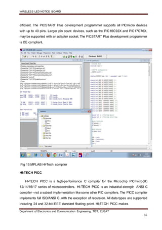
  • 34. WIRELESS LED NOTICE BOARD Department of Electronics and Communication Engineering, TIST, CUSAT 34 The MPLAB IDE is a Windows®-based application that contains: • An interface to debugging tools simulator o Programmer (sold separately) o Emulator (sold separately) o In-circuit debugger (sold separately) • A full-featured editor • A project manager • Customizable toolbar and key mapping • A status bar • On-line help The MPLAB IDE allows you to: • Edit your source files (either assembly or ‘C’) • One touch assemble (or compile) and download to PICmicro emulator and simulator tools (automatically updates all project information). • Debug using: o source files o absolute listing file o Machine code The ability to use MPLAB IDE with multiple debugging tools allows users to easily switch from the cost effective simulator to a full-featured emulator with minimal retraining. PICSTART Plus Entry Level Development Programmer The PICSTART Plus development programmer is an easy-to-use, low cost, prototype programmer. It connects to the PC via a COM (RS-232) port. MPLAB Integrated Development Environment software makes using the programmer simple and
  • 35. WIRELESS LED NOTICE BOARD Department of Electronics and Communication Engineering, TIST, CUSAT 35 efficient. The PICSTART Plus development programmer supports all PICmicro devices with up to 40 pins. Larger pin count devices, such as the PIC16C92X and PIC17C76X, may be supported with an adapter socket. The PICSTART Plus development programmer is CE compliant. Fig 16.MPLAB HI-Tech compiler HI-TECH PICC HI-TECH PICC is a high-performance C compiler for the Microchip PICmicro(R) 12/14/16/17 series of microcontrollers. HI-TECH PICC is an industrial-strength ANSI C compiler - not a subset implementation like some other PIC compilers. The PICC compiler implements full ISO/ANSI C, with the exception of recursion. All data types are supported including 24 and 32-bit IEEE standard floating point. HI-TECH PICC makes
  • 36. WIRELESS LED NOTICE BOARD Department of Electronics and Communication Engineering, TIST, CUSAT 36 full use of specific PIC features and using an intelligent optimizer, can generate high- quality code easily rivaling hand-written assembler. Automatic handling of page and bank selection frees the programmer from the trivial details of assembler code. Compiler PICC can be run entirely from the HI-TECH Professional Development environment†. This environment allows you to manage all of your PIC projects. You can compile, assemble and link your embedded application with a single step. Optionally, the compiler may be run directly from the command line, allowing you to compile, assemble and link using one command. This enables the compiler to be integrated into third party development environments, such as Microchip's MPLAB IDE. Features of the compiler include:  ANSI C - full featured and portable  Reliable - mature, field-proven technology  Multiple C optimization levels  An optimizing assembler  Full linker, with overlaying of local variables to minimize RAM usage  Comprehensive C library with all source code provided  Includes support for 24-bit and 32-bit IEEE floating point and 32-bit long data types  Mixed C and assembler programming  Unlimited number of source files  Listings showing generated assembler  Compatible - integrates into the MPLAB IDE, MPLAB ICD and most 3rd-party development tools The PICC compiler supports all of the Microchip PIC12xx, PIC14000, PIC16xx and PIC17xx series microcontroller.
  • 37. WIRELESS LED NOTICE BOARD Department of Electronics and Communication Engineering, TIST, CUSAT 37 CHAPTER .6 COST OF CONSTRUCTION SL.NO COMPONENT QUANTITY RATE AMOUNT 1 BRY 9V’HW’ 2 15.00 30.00 2 SOC-ZIP SOCKET 40 PIN 1 75.00 75.00 3 CAPACITOR AEC 20 1.00 20.00 4 LED RED 5MM 2 2.00 4.00 5 9PIN D CONNECTORPCB M/F 1 20.00 20.00 6 TRS BF 494B 2 4.00 8.00 7 XTL 4MHZ 1 8.00 8.00 8 CON 40 PIN BURG STRIP 1 8.00 8.00 9 CON 40 PIN BURG STRIP SOCKET 1 12.00 12.00
  • 38. WIRELESS LED NOTICE BOARD Department of Electronics and Communication Engineering, TIST, CUSAT 38 10 CAP 1/63V CAPS 5 1.50 7.50 11 SWL MICRO SWITCH 6PIN T/S M39 2 8.00 16.00 12 SWL MICRO SWITCH AIWA M13/M12 2 4.00 8.00 13 RES.25W RES IMP 20 0.50 10.00 14 PIC16F877A 1 160.0 160.00 15 TXR 9-0-9 500MA HONDA 1 40.00 40.00 16 REG 7805 1 7.00 7.00 17 WIR 1/23 SINGLE STAND MTR 5 4.00 20.00 18 PCB 2X3 DOT PCB 1 9.00 9.00 19 VC SINGLE VC J/S 1.00 6.00 6.00 20 DIP WO4 BR 1 5.00 5.00 21 CAP 10/63V CAP’S 1 1.00 1.00 22 CAP 100/25V CAP’S 1 1.00 1.00 23 RES .25W RES IMP 4 0.25 1.00 24 74HC595 DRIVER 10 14.00 140.00 25 ULN 2003 2 10.00 20.00
  • 39. WIRELESS LED NOTICE BOARD Department of Electronics and Communication Engineering, TIST, CUSAT 39 CONCLUSION
  • 40. WIRELESS LED NOTICE BOARD Department of Electronics and Communication Engineering, TIST, CUSAT 40 CHAPTER .7 CONLUSION Present day in schools, colleges and in many industrial areas broadcasting of important Notices, data and message is a manual labour work that gives lot of hardship and workload for the people involved in reading out Notices and messages to different sections of the institute resulting in wasting of lot of precious working time. So in order to overcome this hardship, we have prepared a circuit that wirelessly connects different digital LED NOTICE BOARD located at different sections to a single server location from which the data or information to be communicated can be broadcasted. The information to be broadcasted can edited as per the requirement at the server location and the result will be reflected at the respective sections of an institute or an industry. The to design easy to implement.
  • 41. WIRELESS LED NOTICE BOARD Department of Electronics and Communication Engineering, TIST, CUSAT 41 FUTURSCOPE
  • 42. WIRELESS LED NOTICE BOARD Department of Electronics and Communication Engineering, TIST, CUSAT 42 CHAPTER .8 FUTURESCOPE This wireless LED display can be implemented in places where the area is large like a college or an IT park. This is useful because a single transmitter can be used to send to multiple receivers.
  • 43. WIRELESS LED NOTICE BOARD Department of Electronics and Communication Engineering, TIST, CUSAT 43 BIBLIOGRAPHY
  • 44. WIRELESS LED NOTICE BOARD Department of Electronics and Communication Engineering, TIST, CUSAT 44 CHAPTER .9 BIBLIOGRAPHY  http://ww1.microchip.com/downloads/en/devicedoc/39582b.pdf  http://site.gridconnect.com/docs/MaxStream/XBee_Manual_GC.pdf  http://en.wikipedia.org/wiki/MAX232  http://www.datasheetcatalog.org/datasheet/texasinstruments/max232.pdf  http://www.omega.com/techref/pdf/rs-232.pdf  http://www.nxp.com/documents/data_sheet/74HC_HCT595.pdf