


Antenna presentation PPT
- 1. Applied Electromagnetics , Microwaves & Antenna Name :- Mr.kadam Sachin Pandurang (B.Sci.(Electronic science)& M.Sci(Electronics science –Appear 2020).)
- 2. What is Antenna ? • Antenna (or sometimes called as an Aerial), is an electrical device that converts electric power into electromagnetic waves (or simply radio waves) and vice-versa. • A signal from a transmission line or the guiding device (hence the term guided wave) like a co- axial cable, is given to an antenna, which then converts the signal into electromagnetic energy to be transmitted through space (hence the term free space). Flow of signal
- 3. Why do we need Antennas? There are several reasons as to why we need or why we use antennas, but an important reason as to why we use antennas is that they provide a simple way to transfer signals (or data) where other methods are impossible. For example, take the case of an Aeroplane. The pilot needs to frequently communicate with the ATC personnel. If would not make any sense if we tie up a cable (of dynamically variable length) to the tail of the plane and connect it to the ATC. Wireless communication is the only feasible option and Antennas are the gateway for that. There are many situations or applications where cables are preferred over wireless communication with antennas (like high speed ethernet or the connection between gaming console and the T.V., for example).
- 4. Different Types Of Antenna Wire Antennas Short Dipole Antenna Dipole Antenna Loop Antenna Monopole Antenna Log Periodic Antennas Bow Tie Antennas Log-Periodic Antennas Log-Periodic Dipole Array Aperture Antennas Slot Antenna Horn Antenna Microstrip Antennas Rectangular Microstrip Patch Antenna Quarter-Wave Patch Antenna Reflector Antennas Flat-plate Reflector Antenna Corner Reflector Antenna Parabolic Reflector Antenna Lens Antennas Travelling-wave Antennas Long Wire Antenna Yagi–Uda Antenna Helical Wire Antenna Spiral Antenna Array Antennas Two-Element Array Antenna Linear Array Antenna Phased Array Antennas
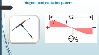
- 5. 1) λ/2 Antenna {Dipole Antenna } In radio and telecommunications a dipole antenna or doublet is the simplest and most widely used class of antenna.The dipole is any one of a class of antennas producing a radiation pattern approximating that of an elementary electric dipole with a radiating structure supporting a line current so energized that the current has only one node at each end. This antenna introduce by German physicist Heinrich Hertz first demonstrated the existence of radio waves in 1887 using what we now know as a dipole antenna (with capacitive-end- loading). A dipole antenna commonly consists of two identical conductive elements such as metal wires or rods. The driving current from the transmitter is applied, or for receiving antennas the output signal to the receiver is taken, between the two halves of the antenna. Each side of the feedline to the transmitter or receiver is connected to one of the conductors.
- 6. Diagram and radiation pattern
- 7. Advantages & Disadvantages of Dipole Antenna Advantages :- Balance:-Dipole antennas offer the advantage of receiving balanced signals. The two-pole design enables the device to receive signals from a variety of frequencies. It also helps the device sort out problems caused by conflicting signals without losing reception quality. Design Options :- In addition to the basic, television-top dipole antenna, many other forms exist. Folded dipole antennas have ends that turn back toward the center to help maximize the signal strength. Other options include the half-wave dipole, the folded dipole and the half-wave folded dipole. Disadvantages :- Size :-Although the indoor dipole antennas are usually small, the outdoor versions can be large and difficult to manage. They often require more than one person to install, as the poles might be tall and unwieldy. The size makes these outdoor versions difficult to transport, move and install when necessary. Moving It :- If you're using a small, TV-top dipole antenna, you must try multiple combinations of pole placements before finding the best reception position. Both poles typically rotate and extend, making it a hassle to move one and then the other continuously while seeking maximum reception.
- 8. 2) Horn Antenna Horn antenna coverts the electric power in to the radio waves and vice versa .it is usually used with a radio transmitter or radio receiver A horn antenna or microwave horn is an antenna that consist of a flaring metal waveguide shaped like a horn to direct radio waves in a beam It provides a gradual transmission structure to match the impedance of a tube to the impedance of free space ,enabling the waves from the tube to radiate efficiently into space Horns are widely used as antennas at UHF and microwave frequencies, above 300MHz.
- 9. Advantages & Disadvantages Of Horn Antenna Advantages of Horn Antenna: ➨It is simple in construction. ➨It delivers adequate directivity. ➨It offers bandwidth of about 10%. ➨Horn antenna along with parabolic reflector disc can deliver high gain. Disadvantages of Horn Antenna: ➨Horn antenna radiates energy in spherical wave front shape, as a result horn antenna does not provide sharp/directive beam. ➨Usually gain of horn antenna is limited to 20dB. This is due to the fact that in order to increase the gain when the horn opening is made larger, the length of horn also becomes excessive.
- 10. 3) Parabolic Dish Antenna The parabolic reflector or dish antenna is the form of antenna which finds many uses in domestic satellite television reception, terrestrial microwave data links, general satellite communications and many more. Its size means that it is generally limited to use above 1GHz, although larger antennas may be used for frequencies down to about 100MHz. The parabolic reflector antenna or dish antenna is known for its distinctive shape, its high gain, and narrow beam widths. It is the performance which can be achieved by using one is the reason it is so widely used at higher frequencies. The standard definition of a parabola is - Locus of a point, which moves in such a way that its distance from the fixed point (called focus) plus its distance from a straight line (called directrix) is constant. Cassegrain Antenna
- 11. Radiation Pattern Of Parabolic Dish Antenna When the antenna acts as a transmitting antenna, the energy from the feed radiates through a horn antenna onto the hyperboloid concave reflector, which again reflects back on to the parabolic reflector. The signal gets reflected into the space from there. Hence, wastage of power is controlled and the directivity gets improved. When the same antenna is used for reception, the electromagnetic waves strike the reflector, gets reflected on to the concave hyperboloid and from there, it reaches to the feed. A wave guide horn antenna presents there to receive this signal and sends to the receiver circuitry for amplification. The above figure shows the working model of cassegrain feed.
- 12. Advantages & Disadvantages Of parabolic dish Antenna Advantages Of Parabolic Reflector Antenna − Reduction of minor lobes Wastage of power is reduced Equivalent focal length is achieved Feed can be placed in any location, according to our convenience Adjustment of beam (narrowing or widening) is done by adjusting the reflecting surfaces Disadvantage Of A Parabolic Reflector Antenna − Some of the power that gets reflected from the parabolic reflector is obstructed. This becomes a problem with small dimension paraboloid. applications of Parabolic reflector antenna − The Cassegrain feed parabolic reflector is mainly used in satellite communications. Also used in wireless telecommunication systems.
- 13. 4) Antenna array An antenna array is a radiating system, which consists of individual radiators and elements. Each of this radiator, while functioning has its own induction field. The elements are placed so closely that each one lies in the neighbouring one’s induction field. Therefore, the radiation pattern produced by them, would be the vector sum of the individual ones. The following image shows another example of an antenna array. The spacing between the elements and the length of the elements according to the wavelength are also to be kept in mind while designing these antennas. The antennas radiate individually and while in array, the radiation of all the elements sum up, to form the radiation beam, which has high gain, high directivity and better performance, with minimum losses.
- 14. Advantages Of Using Antenna Arrays − The signal strength increases High directivity is obtained Minor lobes are reduced much High Signal-to-noise ratio is achieved High gain is obtained Power wastage is reduced Better performance is obtained Disadvantages Of Array Antennas − Resistive losses Probability is increased Mounting and maintenance is difficult Huge external space is required • Applications Of Array Antennas − o Used in satellite communications o Used in wireless communications o Used in military radar communications o Used in the astronomical study • The Basic Types Of Arrays Are : − • Collinear array • Broad side array • End fire array • Parasitic array • Yagi - Uda array • Log - periodic array • Turnstile array • Super - turnstile array
- 15. APPLICATIONS OF DIFFERENT TYPES OF ANTENNA