Dynamic Assignment of Traffic Classes to a Priority Queue in a Packet Forwarding Device
1 like247 views

The document is a patent application publication for a method and apparatus designed for the dynamic assignment of traffic classes to a priority queue in packet forwarding devices. It addresses challenges in packet-switched networks, such as variable queuing delays and bottlenecks, by monitoring bandwidth usage and adjusting traffic priorities accordingly. The invention aims to improve real-time data stream handling and overall network efficiency.

![Patent Application Publication Apr. 17, 2014 Sheet 2 of 6 US 2014/0105025 A1
t:~G·""': i1A·· ~ . ~ · .. ::-: k.... . ·-.-.-.-.-.-.-.·.-.-.-..-.-.-.-.-.-.-.-.-.-..-.-.-.·.·.·.·.·.·.·.·.·.·.·.·.·.·.·.·.·.·.·.·.·.·.·.·.·.·.·.·.·.·.v
i __ ,,
/'-... .... bs
~t ... ·~ ,, ............ ~
I~ l )H)' :t ~· ~~·5·
.. :S··~
~~~$(; <~;~~ ~
~ t:~·~.:t: ~ ;:--:: r '.f~ ~ ~ :~. . ~ -e -~~. ..- .:: ~> ~ ~ ' ·- ~
/·61
· ~ ~ Ol~e=u~
~.. ...............................,. . ..........................~. .. ......................................................·
~ ;(~{{. 59·. !
.., .. , .. ...". ',· ....' · .'·'·· .•.,.. ·..- .'*.-:'... : ....... ·.·:-.·.·.·.·.·.·.·.·.·.·.·.··· .·.·.·.·.·.·.·.·.·.·.·.·.·.·.·.·.·.·;:: ·~ </ '''-:
, l ~~S:St>C)t~t&) F·v! -~<'~... k··.,~ " ;~:;,; ~."',:; ·•~ [*-~l;. /:. ~ ·~ i l E~~)1f)t N~~~v ~
w ..................... .... '...., dontb . :: Ct~H HtHMkH ~
.,,: Ye$ :,,1,, ~""""'""'"" ...". '".. .. """"'"J . .',:.·', , . I"" """'""'"""'"~"""""""""""~ ,, . I kkvk ~ l ·!f
~ r~·~~(~~.z~t f~.{Jf.ltfy ~.--""'---------~c......-------------~------""'
l,,,,,,,,,,'*''''''''''''~:::::::::::::::::::::::J·· '7 ·'1
r···········l ... :.'::·: ........ .
l.... ·-r ... t~8 Jl~~ trdt
r~£tt~k(7;-t
Nn
"'""":~""::'"'"'""!!>
Yws
![~~~~~]···· 83
•. '~,r ·.•.•i. :.·.~ .•• ~ •. :.·_-,~-.,~,~,-.~.--~.'-~-~,.-.-~;,~.~.t.:.· ..: _,· ,..~::_;~~~: ':~.:~.(~;~~:-::~.:: .,.:_.-_~l~ as :: ~ ..... :.~ ....... ~ ... -....x: ..... ~z ..... ~~...... ~
:: t::::: :: :::::: :: ::::~::::: ::::::::: :: ::::::~
L"""'"""'"'"""""""""""'"""""""""""'"""'"'""':t"""""""'""'""'"""""""'](https://image.slidesharecdn.com/us20140105025dynamicassignmentoftrafficclassestoapriorityqueueinapacketforwardingdevice-141112112921-conversion-gate02/85/Dynamic-Assignment-of-Traffic-Classes-to-a-Priority-Queue-in-a-Packet-Forwarding-Device-3-320.jpg)


fF$ 1·cl:~~t~:t:):~;$~
fP Pt)ft
~~p Ptt~~(H:~t)t~](https://image.slidesharecdn.com/us20140105025dynamicassignmentoftrafficclassestoapriorityqueueinapacketforwardingdevice-141112112921-conversion-gate02/85/Dynamic-Assignment-of-Traffic-Classes-to-a-Priority-Queue-in-a-Packet-Forwarding-Device-5-320.jpg)
![US 2014/0105025 AI
DYNAMIC ASSIGNMENT OF TRAFFIC
CLASSES TO A PRIORITY QUEUE IN A
PACKET FORWARDING DEVICE
CROSS-REFERENCE TO RELATED
APPLICATION
[0001] The present application claims priority under 35
U.S.C. § 119( e) from provisional application Ser. No. 60/226,
787, and is related to U.S. patent application Ser. No. 09/227,
389, both applications being incorporated herein by reference.
FIELD OF THE INVENTION
[0002] The present invention relates to the field of telecommunications,
and more particularly to dynamic assignment of
traffic classes to queues having different priority levels.
BACKGROUND OF THE INVENTION
[0003] The flow of packets through packet-switched networks
is controlled by switches and routers that forward
packets based on destination information included in the
packets themselves. A typical switch or router includes a
number of input/output (I/0) modules connected to a switching
fabric, such as a crossbar or shared memory switch. In
some switches and routers, the switching fabric is operated at
a higher frequency than the transmission frequency of the I/0
modules so that the switching fabric may deliver packets to an
I/0 module faster than the I/0 module can output them to the
network transmission medium. In these devices, packets are
usually queued in the I/0 module to await transmission.
[0004] One problem that may occur when packets are
queued in the I/0 module or elsewhere in a switch or router is
that the queuing delay per packet varies depending on the
amount of traffic being handled by the switch. Variable queuing
delays tend to degrade data streams produced by real-time
sampling (e.g., audio and video) because the original time
delays between successive packets in the stream convey the
sampling interval and are therefore needed to faithfully reproduce
the source information. Another problem that results
from queuing packets in a switch or router is that data from a
relatively important source, such as a shared server, may be
impeded by data from less important sources, resulting in
bottlenecks.
SUMMARY OF THE INVENTION
[0005] A method and apparatus for dynamic assignment of
classes of traffic to a priority queue are disclosed. Bandwidth
consumption by one or more types of packet traffic received
in a packet forwarding device is monitored. The queue assignment
of at least one type of packet traffic is automatically
changed from a queue having a first priority to a queue having
a second priority if the bandwidth consumption exceeds the
threshold.
[0006] Other features and advantages of the invention will
be apparent from the accompanying drawings and from the
detailed description that follows below.
BRIEF DESCRIPTION OF THE DRAWINGS
[0007] The present invention is illustrated by way of
example and not limitation in the figures of the accompanying
drawings in which like references indicate similar elements
and in which:
1
Apr. 17, 2014
[0008] FIG. 1 illustrates a packet forwarding device that
can be used to implement embodiments of the present invention;
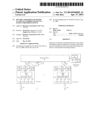
[0009] FIG. 2A illustrates queue fill logic implemented by
a queue manager in a quad interface device, and FIG. 2B
illustrates queue drain logic according to one embodiment;
[0010] FIG. 3 illustrates the flow of a packet within the
switch of FIG. 1;
[0011] FIG. 4 illustrates storage of an entry in an address
resolution table managed by an address resolution unit;
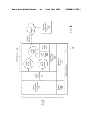
[0012] FIG. 5 is a diagram of the software architecture of
the switch of FIG. 1 according to one embodiment; and
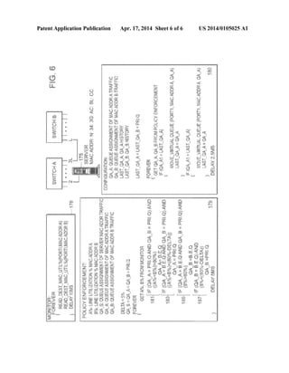
[0013] FIG. 6 illustrates an example of dynamic assignment
of traffic classes to a priority queue.
DETAILED DESCRIPTION OF THE PRESENTLY
PREFERRED EXEMPLARY EMBODIMENTS
[0014] A packet forwarding device in which selected
classes of network traffic may be dynamically assigned for
priority queuing is disclosed. In one embodiment, the packet
forwarding device includes a Java virtual machine for executing
user-coded Java applets received from a network management
server (NMS). A Java-to-native interface (JNI) is provided
to allow the Java applets to obtain error information and
traffic statistics from the device hardware and to allow the
Java applets to write configuration information to the device
hardware, including information that indicates which classes
of traffic should be queued in priority queues. The Java
applets implement user-specified traffic management policies
based on real-time evaluation of the error information and
traffic statistics to provide dynamic control of the priority
queuing assignments. These and other aspects and advantages
of the present invention are described below.
[0015] It should be noted that the use of the Java language
is not a requirement for practicing the present invention.
Although Java provides a number of advantages when used to
implement the present invention, e.g., dynamic on-demand
use, other programming languages such as C may be used in
its place.
[0016] FIG. 1 illustrates a packet forwarding device 17 that
can be used to implement embodiments of the present invention.
For the purposes of the present description, the packet
forwarding device 17 is assumed to be a switch that switches
packets between ingress and egress ports based on media
access control (MAC) addresses within the packets. In an
alternate embodiment, the packet forwarding device 17 may
be a router that routes packets according to destination internet
protocol (IP) addresses or a routing switch that performs
both MAC address switching and IP address routing. The
techniques and structures disclosed herein are applicable generally
to a device that forwards packets in a packet switching
network. Also, the term packet is used broadly herein to refer
to a fixed-length cell, a variable length frame or any other
information structure that is self-contained as to its destination
address.
[0017] The switch 17 includes a switching fabric 12
coupled to a plurality ofl/0 units (only I/0 units 1 and 16 are
depicted) and to a processing unit 10. The processing unit
includes at least a processor 31 (which may be a microprocessor,
digital signal processor or microcontroller) coupled to
a memory 32 via a bus 33. In one embodiment, each I/0 unit
1, 16 includes four physical ports P1-P4 coupled to a quad
media access controller (QMAC) 14A, 14B via respective
transceiver interface units 21A-24A, 21B-24B. Each I/0 unit](https://image.slidesharecdn.com/us20140105025dynamicassignmentoftrafficclassestoapriorityqueueinapacketforwardingdevice-141112112921-conversion-gate02/85/Dynamic-Assignment-of-Traffic-Classes-to-a-Priority-Queue-in-a-Packet-Forwarding-Device-8-320.jpg)
![US 2014/0105025 AI
1, 16 also includes a quad interface device (QID) 16A, 16B,
an address resolution unit (ARU) 15A, 15B and a memory
18A, 18B, interconnected as shown in FIG. 1. Preferably, the
switch 17 is modular with at least the I/0 units 1, 16 being
implemented on port cards (not shown) that can be installed in
a backplane (not shown) of the switch 17. In one implementation,
each port card includes a given number ofl/0 units and
therefore supports a corresponding number of physical ports.
The switch backplane includes slots for a given number of
port cards, so that the switch 17 can be scaled according to
customer needs to support a number of physical ports as
controlled by the number of port cards. In alternate embodiments,
each I/0 unit 1, 16 may support more or fewer physical
ports each port card may support more or fewerl/0 units 1, 16
and the switch 17 may support more or fewer port cards. For
example, the I/0 unit 1 shown in FIG. 1 may be used to
support ObaseT transmission lines (i.e., 10 Mbps (mega-bit
per second), twisted-pair) or OObaseF transmission lines (1 00
Mbps, fiber optic), while a different I/0 unit (not shown) may
be used to support a 1 OOObaseF transmission line (1000
Mbps, fiber optic). Nothing disclosed herein should be construed
as limiting embodiments of the present invention to use
with a particular transmission medium, I/0 unit, port card or
chassis configuration.
[0018] Still referring to FIG. 1, when a packet 25 is received
on physical port Pl, it is supplied to the corresponding physical
transceiver 21A which performs any necessary signal
conditioning (e.g. optical to electrical signal conversion) and
then forwards the packet 25 to the QMAC 14A. The QMAC
14A buffers packets received from the physical transceivers
21A-24A as necessary, forwarding one packet at a time to the
Q ID 16A. Receive logic within the Q ID 16A notifies the ARU
15A that the packet 25 has been received. TheARU computes
a table index based on the destination MAC address within the
packet 25 and uses the index to identify an entry in a forwarding
table that corresponds to the destination MAC address. In
packet forwarding devices that operate on different protocol
layers of the packet (e.g., routers), a forwarding table may be
indexed based on other destination information contained
within the packet.
[0019] According to one embodiment, the forwarding table
entry identified based on the destination MAC address indicates
the switch egress port to which the packet 25 is destined
and also whether the packet is part of a MAC-address based
virtual local area network (VLAN), or a port-based VLAN.
(As an aide a VLAN is a logical grouping of MAC addresses
(a MAC-address-based VLAN) or a logical grouping of
physical ports (a port-based VLAN).) The forwarding table
entry further indicates whether the packet 25 is to be queued
in a priority queue in the I/0 unit that contains the destination
port. As discussed below, priority queuing may be specified
based on a number of conditions, including, but not limited to,
whether the packet is part of a particular IP flow, or whether
the packet is destined for a particular port, VLAN or MAC
address.
[0020] According to one embodiment, the QID 16A, 16B
segments the packet 25 into a plurality of fixed-length cells 26
for transmission through the switching fabric 12. Each cell
includes a header 28 that identifies it as a constituent of the
packet 25 and that identifies the destination port for the cell
(and therefore for the packet 25). The header 28 of each cell
also includes a bit 29 indicating whether the cell is the beginning
cell of a packet and also a bit 30 indicating whether the
2
Apr. 17, 2014
packet 25 to which the cell belongs is to be queued in a
priority queue or a best effort queue on the destined I/0 unit.
[0021] The switching fabric 12 forwards each cell to the I/0
unit indicated by the cell header 28. In the exemplary data
flow shown in FIG. 1, the constituent cells 26 of the packet 25
are assumed to be forwarded to I/0 unit 16 where they are
delivered to transmit logic within the QID 16B. The transmit
logic in the QID 16B includes a queue manager (not shown)
that maintains a priority queue and a best effort queue in the
memory 18B. In one embodiment, the memory 18B is
resolved into a pool of buffers, each large enough to hold a
complete packet. When the beginning cell of the packet 25 is
delivered to the QID 16B, the queue manager obtains a buffer
from the pool and appends the buffer to either the priority
queue or the best effort queue according to whether the priority
bit 30 is set in the beginning cell. In one embodiment, the
priority queue and the best effort queue we each implemented
by a linked list, with the queue manager maintaining respective
pointers to the head and tail of each linked list. Entries are
added to the tail of the queue list by advancing the tail pointer
to point to a newly allocated buffer that has been appended to
the linked list, and entries are popped off the head of the queue
by advancing the head pointer to point to the next buffer in the
linked list and returning the spent buffer to the pool.
[0022] After a buffer is appended to either the priority
queue or the best effort queue, the beginning cell and subsequent
cells are used to reassemble the packet 25 within the
buffer. Eventually the packet 25 is popped off the head of the
queue and delivered to an egress port via the QMAC 14B and
the physical transceiver (e.g., 23B) in an egress operation.
This is shown by way of example in FIG. 1 by the egress of
packet 25 from physical port P3 ofl/0 unit 16.
[0023] FIG. 2A illustrates queue fill logic implemented by
the queue manager in the QID. Starting at block 51, a cell is
received in the QID from the switching fabric. The beginning
cell bit in the cell header is inspected at decision block 53 to
determine if the cell is the beginning cell of a packet. If so, the
priority bit in the cell header is inspected at decision block 55
to determine whether to allocate an entry in the priority queue
or the best effort queue for packet reassembly. If the priority
bit is set, an entry in the priority queue is allocated at block 57
and the priority queue entry is associated with the portion of
the cell header that identifies the cell as a constituent of a
particular packet at block 59. If the priority bit in the cell
header is not set, then an entry in the best effort queue is
allocated at block 61 and the best effort queue entry is associated
with the portion of the cell header that identifies the cell
as a constituent of a particular packet at block 63.
[0024] Returning to decision block 53, if the beginning cell
bit in the cell header is not set, then the queue entry associated
with the cell header is identified at block 65. The association
between the cell header and the queue entry identified at block
65 was established earlier in either block 59 or block 63. Also,
identification of the queue entry in block 65 may include
inspection of the priority bit in the cell to narrow the identification
effort to either the priority queue or the best effort
queue. In block 67, the cell is combined with the preceding
cell in the queue entry in a packet reassembly operation. If the
reassembly operation in block 67 results in a completed
packet (decision block 69), then the packet is marked as ready
for transmission in block 71. In one embodiment, the packet
is marked by setting a flag associated with the queue entry in](https://image.slidesharecdn.com/us20140105025dynamicassignmentoftrafficclassestoapriorityqueueinapacketforwardingdevice-141112112921-conversion-gate02/85/Dynamic-Assignment-of-Traffic-Classes-to-a-Priority-Queue-in-a-Packet-Forwarding-Device-9-320.jpg)
![US 2014/0105025 AI
which the packet has been reassembled. Other techniques for
indicating that a packet is ready for transmission may be used
in alternate embodiments.
[0025] FIG. 2B illustrates queue drain logic according to
one embodiment. At decision block 75, the entry at the head
of the priority queue is inspected to determine if it contains a
packet ready for transmission. If so, the packet is transmitted
at block 77 and the corresponding priority queue entry is
popped off the head, of the priority queue and deallocated at
block 79. If a ready packet is not present at the head of the
priority queue, then the entry at the head of the best effort
queue is inspected at decision block 81. If a packet is ready at
the head of the best effort queue, it is transmitted at block 83
and the corresponding best effort queue entry is popped off
the head of the best effort queue and deallocated in block 85.
Note that, in the embodiment illustrated in FIG. 2B, packets
are drained from the best effort queue only after the priority
queue has been emptied. In alternate embodiments, a timer,
counter or similar logic element may be used to ensure that
the best effort queue 105 is serviced at least every so often or
at least after every N number of packets are transmitted from
the priority queue, thereby ensuring at least a threshold level
of service to best effort queue.
[0026] FIG. 3 illustrates the flow of a packet within the
switch 17 ofFIG.l.A packet is received in the switch at block
91 and used to identify an entry in a forwarding table called
the address resolution (AR) table at block 93. At decision
block 95, a priority bit in the AR table entry is inspected to
determine whether the packet belongs to a class of traffic that
has been selected for priority queuing. If the priority bit is set,
the packet is segmented into cells having respective priority
bits set in their headers in block 97. If the priority bit is not set,
the packet is segmented into cells having respective priority
bits cleared their cell headers in block 99. The constituent
cells of each packet are forwarded to an egress I/0 unit by the
switching fabric. In the egress I/0 unit, the priority bit of each
cell is inspected (decision block 101) and used to direct the
cell to an entry in either the priority queue 103 or the best
effort queue 105 where it is combined with other cells to
reassemble the packet.
[0027] FIG. 4 illustrates storage of an entry in the address
resolution (AR) table managed by the ARU. In one embodiment,
theAR table is maintained in a high speed static random
access memory (SRAM) coupled to the ARU. Alternatively,
the AR table may be included in a memory within an application-
specific integrated circuit (ASIC) that includes the
ARU. Generally, the ARU stores an entry in the AR table in
response to packet forwarding information from the processing
unit. The processing unit supplies packet forwarding
information to be stored in eachAR table in the switch whenever
a new association between a destination address and a
switch egress port is learned. In one embodiment, an addressto-
port association is learned by transmitting a packet that has
an unknown egress port assigmnent on each of the egress
ports of the switch and associating the destination address of
the packet with the egress port at which an acknowledgment
is received. Upon learning the association between the egress
port and the destination address, the processing unit issues
forwarding information that includes, for example, an identifier
of the newly associated egress port, the destination
MAC address, an identifier of the VLAN associated with the
MAC address (if any), an identifier of the VLAN associated
with the egress port (if any), the destination IP address the
destination IP port (e.g., transmission control protocol (TCP),
3
Apr. 17, 2014
universal device protocol (UDP) or other IP port) and the IP
protocol (e.g., HTTP, FTP or other IP protocol). The source IP
address, source IP port and source IP protocol may also be
supplied to fully identifY an end-to-end IP flow.
[0028] Referring to FIG. 4, forwarding information 110 is
received from the processing unit at block 115. At block 117,
the ARU stores the forwarding information in an AR table
entry. At decision block 119, the physical egress port identifier
stored in the AR table entry is compared against priority
configuration information to determine if packets destined for
the egress port have been selected for priority egress queuing.
If so, the priority bit is set in the AR table entry in block 127.
Thereafter, incoming packets that index the newly stored
table entry will be queued in the priority queue to await
transmission. If packets destined for the egress port have not
been selected for priority queuing, then at decision block 121
the MAC address stored in the AR table entry is compared
against the priority configuration information to determine if
packets destined for the MAC address have been selected for
priority egress queuing. If so, the priority bit is set in the AR
table entry in block 127. If packets destined for the MAC
address have not been selected for priority egress queuing,
then at decision block 123 the VLAN identifier stored in the
AR table entry (if present) is compared against the priority
configuration information to determine if packets destined for
the VLAN have been selected for priority egress queuing. If
so, the priority bit is set in the AR table entry in block 127. If
packets destined for the VLAN have not been selected for
priority egress queuing, then at block 125 the IP flow identified
by the IP address, IP port and IP protocol in the AR table
is compared against the priority configuration information to
determine if packets that form part of the IP flow have been
selected for priority egress queuing. If so, the priority bit is set
in the AR table entry, otherwise the priority bit is not set. Yet
other criteria may be considered in assigning priority queuing
in alternate embodiments. For example, priority queuing may
be specified for a particular IP protocol (e.g. FTP, HTTP).
Also, the ingress port, source MAC address or source VLAN
of a packet may also be used to determine whether to queue
the packet in the priority egress packet. More specifically, in
one embodiment, priority or best effort queuing of unicast
traffic is determined based on destination parameters (e.g.,
egress port, destination MAC address or destination IP
address), while priority or best effort queuing of multicast
traffic is determined based on source parameters (e.g., ingress
port source MAC address or source IP address).
[0029] FIG. 5 is a diagram of the software architecture of
the switch 17 of FIG. 1 according to one embodiment. An
operating system 143 and device drivers 145 are provided to
interface with the device hardware 141. For example, device
drivers are provided to write configuration information and
AR storage entries to the ARU s in respective I/0 units. Also,
the operating system 143 performs memory management
functions and other system services in response to requests
from higher level software. Generally, the device drivers 145
extend the services provided by the operating system and are
invoked in response to requests for operating system service
that involve device-specific operations.
[0030] The device management code 147 is executed by the
processing unit (e.g., element 10 ofFIG. 1) to perform system
level functions, including management of forwarding entries
in the distributed AR tables and management of forwarding
entries in a master forwarding table maintained in the
memory of the processing unit. The device management code](https://image.slidesharecdn.com/us20140105025dynamicassignmentoftrafficclassestoapriorityqueueinapacketforwardingdevice-141112112921-conversion-gate02/85/Dynamic-Assignment-of-Traffic-Classes-to-a-Priority-Queue-in-a-Packet-Forwarding-Device-10-320.jpg)
![US 2014/0105025 AI
147 also includes routines for invoking device driver services,
for example, to query the ARU for traffic statistics and error
information, or to write updated configuration information to
the ARUs, including priority queuing information. Further,
the device management code 147 includes routines for writing
updated configuration information to the ARUs, as discussed
below in reference to FIG. 6. In one implementation,
the device management code 147 is native code, meaning that
the device management code 147 is a compiled set of instructions
that can be executed directly by a processor in the
processing unit to carry out the device management functions.
[0031] In one embodiment, the device management code
147 supports the operation of a Java client 160 that includes a
number of Java applets, including a monitor applet 157, a
policy enforcement applet 159 and configuration applet 161.
A Java applet is an instantiation of a Java class that includes
one or more methods for self initialization (e.g., a constructor
method called "Applet( )"), and one or more methods for
communicating with a controlling application. Typically the
controlling application for a Java applet is a web browser
executed on a general purpose computer. In the software
architecture shown in FIG. 5, however, a Java application
called Data Communication Interface (DCI) 153 is the controlling
application for the monitor, policy enforcement and
configuration applets 157, 159, 161. The DCI application 153
is executed by a Java virtual machine 149 to manage the
download of Java applets from a network management server
(NMS) 170. A library of Java objects 155 is provided for use
by the Java applets 157, 159, 161 and the DCI application
153.
[0032] As above, it should be noted that the use of Java is
not essential to the present invention and is used for purposes
of illustration and explanation. Other programming languages
may be used in its place.
[0033] In one implementation, the NMS 170 supplies Java
applets to the switch 17 in a hyper-text transfer protocol
(HTTP) data stream. Other protocols may also be used. The
constituent packets of the HTTP data stream are addressed to
the IP address of the switch and are directed to the processing
unit after being received by the I/0 unit coupled to the NMS
170. After authenticating the HTTP data stream, the DCI
application 153 stores the Java applets provided in the data
stream in the memory of the processing unit and executes a
method to invoke each applet. An applet is invoked by supplying
the Java virtual machine 149 with the address of the
constructor method of the applet and causing the Java virtual
machine 149 to begin execution of the applet code. Program
code defining the Java virtual machine 149 is executed to
interpret the platform independent byte codes of the Java
applets 157, 159, 161 into native instructions that can be
executed by a processor within the processing unit.
[0034] According to one embodiment, the monitor applet
157, policy enforcement applet 159 and configuration applet
161 communicate with the device management code 147
through a Java-native interface (JNI) 151. The JNI 151 is
essentially an application programming interface (API) and
provides a set of methods that can be invoked by the Java
applets 157, 159, 161 to send messages and receive responses
from the device management code 147. In one implementation,
the JNI 151 includes methods by which the monitor
applet 157 can request the device management code 147 to
gather error information and traffic statistics from the device
hardware 141. The JNI 151 also includes methods by which
4
Apr. 17, 2014
the configuration applet 161 can request the device management
code 147 to write configuration information to the
device hardware 141. More specifically, the JNI 151 includes
a method by which, the configuration applet 161 can indicate
that priority queuing should be performed for specified
classes of traffic, including, but not limited to, the classes of
traffic discussed above in reference to FIG. 4. In this way, a
user-coded configuration applet 161 may be executed by the
Java virtual machine 149 within the switch 17 to invoke a
method in the JNI 151 to request the device management code
147 to write information that assigns selected classes of traffic
to be queued in the priority egress queue. In effect, the configuration
applet 161 assigns virtual queues defined by the
selected classes of traffic to feed into the priority egress
queue.
[0035] As noted above, although a Java virtual machine 149
and Java applets 157, 159, 161 have been described, other
virtual machines, interpreters and scripting languages may be
used in alternate embodiments, Also, as discussed below,
more or fewer Java applets may be used to perform the monitaring,
policy enforcement and configuration functions in
alternate embodiments.
[0036] FIG. 6 illustrates an example of dynamic assignment
traffic classes to a priority queue. An exemplary network
includes switches A and B coupled together at physical ports
32 and 1, respectively. Suppose that a network administrator
or other user determines that an important server 175 on port
2 of switch A requires a relatively high quality of service
(QoS), and that, at least in switch B, the required QoS can be
provided by ensuring that at least 20% of the egress capacity
of switch B, port 1 is reserved for traffic destined to the MAC
address of the server 175. One way to ensure that 20% egress
capacity is reserved to traffic destined for the server 175 is to
assign priority queuing for packets destined to the MAC
address of the server 175, but not for other traffic. While such
an assignment would ensure priority egress to the server
traffic, it also may result in unnecessarily high bandwidth
allocation to the server 175, potentially starving other important
traffic or causing other important traffic to become bottlenecked
behind less important traffic in the best effort queue.
For example, suppose that there are at least two other MAC
address destinations, MAC address A and MAC address B, to
which the user desires to assign priority queuing, so long as
the egress capacity required by the server-destined traffic is
available. In that case, it would be desirable to dynamically
configure the MAC address A and MAC address B traffic to be
queued in either the priority queue or the best effort queue
according to existing traffic conditions. In at least one
embodiment, this is accomplished using monitor, policy
enforcement and configuration applets that have been downloaded
to switch Band which are executed in a Java client in
switch Bas described above in reference to FIG. 5.
[0037] FIG. 6 includes exemplary pseudocode listings of
monitor, policy enforcement and configuration applets 178,
179, 180 that can be used to ensure that at least 20% of the
egress capacity of switch B, port 1 is reserved for traffic
destined to the server 175, but without unnecessarily denying
priority queuing assignment to traffic destined for MAC
addresses A and B. Ater initialization, the monitor applet 178
repeatedly measures of the port 1 line utilization from the
device hardware. In one embodiment, the ARU in the I/0 unit
that manages port 1 keeps a count of the number of packets
destined for particular egress ports, packets destined for particular
MAC addresses, packets destined for particular](https://image.slidesharecdn.com/us20140105025dynamicassignmentoftrafficclassestoapriorityqueueinapacketforwardingdevice-141112112921-conversion-gate02/85/Dynamic-Assignment-of-Traffic-Classes-to-a-Priority-Queue-in-a-Packet-Forwarding-Device-11-320.jpg)
![US 2014/0105025 AI
VLANS, packets that form part of a particular IP low, packets
having a particular IP protocol, and so forth. The ARU also
tracks the number of errors associated with these different
classes of traffic, the number of packets from each class of
traffic that are dropped, and other statistics. By determining
the change in these different statistics per unit time, a utilization
factor may be generated that represents the percent utilization
of the capacity of an egress port, an I/0 unit or the
overall switch. Error rates and packet drop rates may also be
generated.
[0038] In one embodiment, the monitor applet 178 measures
line utilization by invoking methods in the JNI to read
the port 1 line utilization resulting from traffic destined for
MAC address A and for MAC address B on a periodic basis,
e.g., every 10 milliseconds.
[0039] The policy enforcement applet 179 includes variables
to hold the line utilization percentage of traffic destined
for MAC address A (A%), the line utilization percentage of
traffic destined for MAC address B (B% ), the queue assignment
(i.e., priority or best effort) of traffic destined for the
server MAC address (QA_S), the queue assignment of traffic
destined for MAC address A (QA_A) and the queue assignment
of traffic destined for MAC address B. Also, a constant,
DELTA, is defined to be 5% and the queue assignments for the
MAC address A, MAC address B and server MAC address
traffic are initially set to the priority queue.
[0040] The policy enforcement applet 179 also includes a
forever loop in which the line utilization percentages A% and
B % are obtained from the monitor applet 178 and used to
determine whether to change the queue assignments QA_A
and QA_B. If the MAC address A traffic and the MAC
address B traffic are both assigned to the priority queue (the
initial configuration) and the sum of the line utilization percentages
A% and B % exceeds 80%, then less than 20% line
utilization remains for the saver-destined traffic. In that event,
the MAC address A traffic is reassigned from the priority
queue to the best effort queue (code statement 181). If the
MAC address A traffic is assigned to the best effort queue and
the MAC address B traffic is assigned to the priority queue,
then the MAC address A traffic is reassigned to the priority
queue if the sum of the line utilization percentages A % and B
%drops below 80% less DELTA (code statement 183). The
DELTA parameter provides a deadband to prevent rapid
changing of priority queue assignment.
[0041] If the MAC address A traffic is assigned to the best
effort queue and the MAC address B traffic is assigned to the
priority queue and the line utilization percentage B% exceeds
80%, then less than 20% line utilization remains for the
server-destined traffic. Consequently, the MAC address B
traffic is reassigned from the priority queue to the best effort
queue (code statement 185). If the MAC address B traffic is
assigned to the best effort queue and the line utilization percentage
B % drops below 80% less DELTA, then the MAC
address B traffic is reassigned to the priority queue (code
statement 187). Although not specifically provided for in the
exemplary pseudocode listing of FIG. 6, the policy enforcement
applet 179 may treat the traffic destined for the MAC A
and MAC B addresses more symmetrically by including additiona!
statements to conditionally assign traffic destined for
MAC address A to the priority queue, but not traffic destined
for MAC address B. In the exemplary pseudocode listing of
FIG. 6, the policy enforcement applet 179 delays for 5 milliseconds
at the end of each pass through the forever loop
before repeating.
5
Apr. 17, 2014
[0042] The configuration applet 180 includes variables,
QA_A and QA_B, to hold the queue assignments of the traffic
destined for the MAC addresses A and B, respectively. Variables
LAST_QA_A and LAST_QA_B are also provided to
record the history (i.e., most recent values) of the QA_A and
QA_B values. The LAST_QA_A and LAST_QA_B variables
are initialized to indicate that traffic destined for the
MAC addresses A and B is assigned to the priority queue.
[0043] Like the monitor and policy enforcement applets
178, 179, the configuration applet 180 includes a forever loop
in which a code sequence is executed followed by a delay, in
the exemplary listing of FIG. 6, the first operation performed
by the configuration applet 180 within the forever loop is to
obtain the queue assignments QA_A and QA_B from the
policy enforcement applet 179. If the queue assignment indicated
by QA_A is different from the queue assignment indicated
by LAST_QA_A, then a JNI method is invoked to
request the device code to reconfigure the queue assignment
of the traffic destined for MAC address A according to the
new QA_A value. The new QA_A value is then copied into
the LAST_QA_A variable so that subsequent queue assignment
changes are detected. If the queue assignment indicated
by QA_B is different from the queue assignment indicated by
LAST_QA_B, then a JNI method is invoked to request the
device code to reconfigure the queue assignment of the traffic
destined for MAC address B according to the new QA_B
value. The new QA_B value is then copied into the LAST_
QA_B variable so that subsequent queue assignment changes
are detected. By this operation, and the operation of the monitor
and policy enforcement applets 178, 179, traffic destined
for the MAC addresses A and B is dynamically assigned to the
priority queue according to real-time evaluations of the traffic
conditions in the switch.
[0044] Although a three-applet implementation is illustrated
in FIG. 6, more or fewer applets may be used in an
alternate embodiment. For example, the functions of the
monitor, policy enforcement and configuration applets 178,
179, 180 may be implemented in a single applet. Alternatively,
multiple applets may be provided to perform policy
enforcement or other functions using different queue assignment
criteria. For example, one policy enforcement applet
may make priority queue assignments based on destination
MAC addresses, while another policy enforcement applet
makes priority queue assignments based on error rates or line
utilization ofhigher level protocols. Multiple monitor applets
or configuration applets may similarly be provided.
[0045] Although queue assignment policy based on destination
MAC address is illustrated in FIG. 6, myriad different
queue assignment criteria may be used in other embodiments.
For example, instead of monitoring and updating queue
assignment based on traffic to destination MAC addresses,
queue assignments may be updated on other traffic patterns,
including traffic to specified destination ports, traffic from
specified source ports, traffic from specified source MAC
addresses, traffic that forms part of a specified IP flow, traffic
that is transmitted using a specified protocol (e.g., HTTP, FTP
or other protocols) and so forth. Also, queue assignments may
be updated based on environmental conditions such as time of
day, changes in network configuration (e.g., due to failure or
congestion at other network nodes), error rates, packet drop
rates and so forth. Monitoring, policy enforcement and configuration
applets that combine many or all of the above-](https://image.slidesharecdn.com/us20140105025dynamicassignmentoftrafficclassestoapriorityqueueinapacketforwardingdevice-141112112921-conversion-gate02/85/Dynamic-Assignment-of-Traffic-Classes-to-a-Priority-Queue-in-a-Packet-Forwarding-Device-12-320.jpg)
![US 2014/0105025 AI
described criteria may be implemented to provide sophisticated
traffic handling capability in a packet forwarding
device.
[0046] Although dynamic assignment of traffic classes to a
priority egress queue has been emphasized, the methods and
apparatuses described herein may alternatively be used to
assign traffic classes to a hierarchical set of queues anywhere
in a packet forwarding device including, but not limited to,
ingress queues and queues associated with delivering and
receiving packets from the switching fabric. Further,
although the queue assignment of traffic classes has been
described in terms of a pair of queues (priority and best
effort), additional queues in a prioritization hierarchy may be
used without departing from the spirit and scope of the
present invention.
[0047] Further, although the modification of various
queues in this way has been described herein, the invention is
not so limited and other embodiments also exist. For example,
traffic can be filtered based on its type-source (e.g., source
MAC address or source VLAN), ingress port, destination
(e.g., destination. MAC address or destination IP address),
egress port, protocol (e.g., FTP, HTTP) or other hardwaresupported
filters. In one embodiment, filtering of unicast traffic
is determined based on destination parameters such as
egress port, destination MAC address or IP address, while
filtering of multicast traffic is determined based on source
parameters such as ingress port, source MAC address or
source IP address.
[0048] Filtering may be based on environmental conditions,
such as time of day, changes in network configuration
(e.g., due to failure or congestion at other network nodes),
error rates, packet drop rates, line utilization of higher-level
protocols. It may be based on traffic patterns such as traffic
from specified source ports, traffic to specified destination
ports, traffic from specified source MAC addresses or traffic
that forms part of a specified IP flow. Various other hardware
counters, monitors and dynamic values can be read from the
hardware.
[0049] Still further, dynamic filtering decisions may be
made on how to process packets other than choosing whether
they should go to a priority or best effort queue; for example,
they may be dropped or copied, or traffic of a specific type as
described above may be diverted. Packet headers may be
modified, and use of differentiated services (DS), quality of
service (QoS), TOS, TTL, destination and the like is possible
as long as it is supported by the hardware. The configurability
of filtering and subsequent processing in the invention is, in
fact, limited only by the hardware and numerous possibilities
for filtering and subsequent processing of traffic other than
those described herein will be readily apparent to those
skilled in the art after reading and understanding this application.
[0050] As an example, consider the routing of multimedia
traffic. Such traffic might be sent by three or more separated
streams defined by, e.g., virtual port number. This traffic
could be filtered and processed to dynamically add or drop
specific streams. Based on such dynamic adaptation, active
network applications on nodes between the source and destination
can negotiate and dynamically set different adaptation
mechanisms. As described above, the invention is of course
not limited to this example, and in fact is intended to cover
such filtering and processing using future hardware platforms
which provide new capabilities and which afford new ways of
using and controlling such functionality.
6
Apr. 17, 2014
[0051] In the foregoing specification, the invention has
been described with reference to specific exemplary embodiments
thereoflt will, however, be evident that various modifications
and changes may be made to the specific exemplary
embodiments without departing from the broader spirit and
scope of the invention as set forth in the appended claims.
Accordingly, the specification and drawings are to be
regarded in an illustrative rather than a restrictive sense.
1. In a packet forwarding device in a network in which
packet flows are assigned respective classes and each respective
class is accorded a respective packet forwarding treatment,
a method comprising:
detecting a predetermined time of day; and
responsive to detecting the predetermined time of day,
changing the respective packet forwarding treatment
accorded to at least one class of packet flow from a first
packet forwarding treatment to a second packet forwarding
treatment.
2. The method of claim 1, wherein changing the respective
packet flow treatment accorded to the at least one class of
packet flow comprises changing assignment of the at least one
class of packet flow from a queue having a first priority to a
queue having a second priority.
3. The method of claim 1, wherein changing the respective
packet flow treatment accorded to the at least one class of
packet flow comprises dropping packets of the at least one
class of packet flow.
4. The method of claim 1, wherein changing the respective
packet flow treatment accorded to the at least one class of
packet flow comprises copying packets of the at least one
class of packet flow.
5. The method of claim 1, wherein changing the respective
packet flow treatment accorded to the at least one class of
packet flow comprises diverting packets of the at least one
class of packet flow.
6. The method of claim 1, wherein a packet flow is assigned
a respective class based on at least one IP flow parameter of
the packet flow.
7. The method of claim 1, wherein a packet flow is assigned
a respective class based on a respective source of the packet
flow.
8. The method of claim 7, wherein the packet flow is
assigned the respective class based on a MAC address of the
source of the packet flow.
9. The method of claim 7, wherein the packet flow is
assigned the respective class based on a VLAN associated
with the source of the packet flow.
10. The method of claim 1, wherein a packet flow is
assigned a respective class based on a destination of the
packet flow.
11. The method of claim 10, wherein the packet flow is
assigned a respective class based on a MAC address of the
destination of the packet flow.
12. The method of claim 10, wherein the packet flow is
assigned the respective class based on a VLAN associated
with the destination of the packet flow.
13. The method of claim 1, wherein the packet flow is
assigned a respective class based on an ingress port associated
with the packet flow.
14. The method of claim 1, wherein the packet flow is
assigned a respective class based on an egress port associated
with the packet flow.](https://image.slidesharecdn.com/us20140105025dynamicassignmentoftrafficclassestoapriorityqueueinapacketforwardingdevice-141112112921-conversion-gate02/85/Dynamic-Assignment-of-Traffic-Classes-to-a-Priority-Queue-in-a-Packet-Forwarding-Device-13-320.jpg)

Dynamic Assignment of Traffic Classes to a Priority Queue in a Packet Forwarding Device
- 1. 111111 1111111111111111111111111111111111111111111111111111111111111111111111111111 US 20140105025Al (19) United States c12) Patent Application Publication Lavian et al. (10) Pub. No.: US 2014/0105025 A1 (43) Pub. Date: Apr. 17, 2014 (54) DYNAMIC ASSIGNMENT OF TRAFFIC CLASSES TO A PRIORITY QUEUE IN A PACKET FORWARDING DEVICE (71) Applicant: Rockstar Consortium US LP, Plano, TX (US) (72) Inventors: Tal Lavian, Sunnyvale, CA (US); Stephen Lau, Milpitas, CA (US) (73) Assignee: Rockstar Consortium US LP, Plano, TX (US) (21) Appl. No.: 14/134,230 (22) Filed: Dec. 19, 2013 Related U.S. Application Data (63) Continuation of application No. 09/747,296, filed on Dec. 22, 2000, now Pat. No. 8,619,793. ······:!OUnit l (60) Provisional application No. 60/226,787, filed on Aug. 21, 2000. Publication Classification (51) Int. Cl. H04L12/865 (2006.01) (52) U.S. Cl. CPC .................................. H04L 4716275 (2013.01) USPC .......................................................... 370/235 (57) ABSTRACT Responsive to detecting a predetermined time of day, packet forwarding treatment is changed in accordance with at least one class of packet flow from a first packet forwarding treatment to a second packet forwarding treatment. Pro~>z9;:ir:q Unit 10
- 2. Patent Application Publication Apr. 17, 2014 Sheet 1 of 6 US 2014/0105025 A1 ~:i!J: j ' l.t "'' ~1~~~ 1 L .............. ... "''- 00·' ~ IE~~~ ~ .. -~~: ·~ .... ·: ~ t ... ·.·.·.·.·.·.·.·.·.·.·.·.·.·.·.·.·.~
- 3. Patent Application Publication Apr. 17, 2014 Sheet 2 of 6 US 2014/0105025 A1 t:~G·""': i1A·· ~ . ~ · .. ::-: k.... . ·-.-.-.-.-.-.-.·.-.-.-..-.-.-.-.-.-.-.-.-.-..-.-.-.·.·.·.·.·.·.·.·.·.·.·.·.·.·.·.·.·.·.·.·.·.·.·.·.·.·.·.·.·.·.v i __ ,, /'-... .... bs ~t ... ·~ ,, ............ ~ I~ l )H)' :t ~· ~~·5· .. :S··~ ~~~$(; <~;~~ ~ ~ t:~·~.:t: ~ ;:--:: r '.f~ ~ ~ :~. . ~ -e -~~. ..- .:: ~> ~ ~ ' ·- ~ /·61 · ~ ~ Ol~e=u~ ~.. ...............................,. . ..........................~. .. ......................................................· ~ ;(~{{. 59·. ! .., .. , .. ...". ',· ....' · .'·'·· .•.,.. ·..- .'*.-:'... : ....... ·.·:-.·.·.·.·.·.·.·.·.·.·.·.··· .·.·.·.·.·.·.·.·.·.·.·.·.·.·.·.·.·.·;:: ·~ </ '''-: , l ~~S:St>C)t~t&) F·v! -~<'~... k··.,~ " ;~:;,; ~."',:; ·•~ [*-~l;. /:. ~ ·~ i l E~~)1f)t N~~~v ~ w ..................... .... '...., dontb . :: Ct~H HtHMkH ~ .,,: Ye$ :,,1,, ~""""'""'"" ...". '".. .. """"'"J . .',:.·', , . I"" """'""'"""'"~"""""""""""~ ,, . I kkvk ~ l ·!f ~ r~·~~(~~.z~t f~.{Jf.ltfy ~.--""'---------~c......-------------~------""' l,,,,,,,,,,'*''''''''''''~:::::::::::::::::::::::J·· '7 ·'1 r···········l ... :.'::·: ........ . l.... ·-r ... t~8 Jl~~ trdt r~£tt~k(7;-t Nn "'""":~""::'"'"'""!!> Yws ![~~~~~]···· 83 •. '~,r ·.•.•i. :.·.~ .•• ~ •. :.·_-,~-.,~,~,-.~.--~.'-~-~,.-.-~;,~.~.t.:.· ..: _,· ,..~::_;~~~: ':~.:~.(~;~~:-::~.:: .,.:_.-_~l~ as :: ~ ..... :.~ ....... ~ ... -....x: ..... ~z ..... ~~...... ~ :: t::::: :: :::::: :: ::::~::::: ::::::::: :: ::::::~ L"""'"""'"'"""""""""""'"""""""""""'"""'"'""':t"""""""'""'""'"""""""'
- 4. Patent Application Publication Apr. 17, 2014 Sheet 3 of 6 US 2014/0105025 A1 :,'=,,_ ................. t ............... . ~r~t~(n< .:-t::J~. 'TEt~l=& ···.····~)~~ , .•. •.•.•.•.••.••.••.••.••.••k •.••.••.••.••.••.••.••. r,:·-·.·.·.·.·.·.·.·.·.·.·.·.·.·.:~::.. :~~:~~'~:~ ~~~~~:~:) ..· .·.·.·.·.·.·.·.·.·.·.·.·.·.·.·.·.·.·. ... ss =! ~;;: :h ~ r:l ..... ·? . : no 97 ! Yes ·j: ......... . ,ji,... '""""'""""""""""""'*"""':.;/.:: ....... .. :I.·.' ·····'""""!~;~~-;~::!~~-·~::.·~~~~-··· ,s?g::e;:~ r~~~G~.#t ~r~t~) {~.;:.~~~=~~~ ~---i~~n:~{} ~n1<~~ ::;.>t$~~~ f"'{?lt:J:!n~ . r)ri~:Jr~ty t%n {;h:~0rfrd F~r~~~)ray~ ~EJ}·~ C!hs~:~~:~j ! ~ c:f:::r ~r~~tJ:mti-~~r :in <>~~l:! ~~i(~fM:hbr """"""""""""""'"""'i'""'*"'""'*"'""',.,.,.,.,~ .. l_.:.:. ...· .·.·.·.·.·.·.·.·.·.·.·.·.·.·.·.·.·.·.·.·.·.·.·.·.·.·.·.·.·.·.·.·.·.·.·.·:-t.:.:.:.:.:.:.:.:.:.:.:.:.:.:.:.:.:.:.:.:.:.:. ..: . ..: . ..: . ..: . ..: . .. f .,. ......................................................................................t. .............................................................................................., ,,,,,,,,,,,,,,,,,,,,,,,,,,,,-.:...-.:...-.:...-.:...-.:...-.:...-«. ·j ~ r~r;t~(a;t (J:~J()~~:f) .. ~ (:~'-:. ~-.lhl. .- 0. *,_. ...: :!?.::. ... r~;;~·;~;;i;-- Nt) ~ B:i: t ~~~~~~~~~~~~~~~~~~~l- '''' 1................... ~ ... ~. ~ {' 1... .............. .. r.................................... r .......................... . 1 {}1 : : f~--~--~--~--~--~--~--~--~--~~ F~{1(»~~wt ~:: {}f:Z~-iS:5
- 5. Patent Application Publication Apr. 17, 2014 Sheet 4 of 6 115-J=$;}¢= ·~.. ................................................". '.. .................................~. .. .............................................". '.. ..............................-.. : I -~ -~ 7 ....... r····r~-i:~;-~:~~·;~:~--~;~~~;~·;~::j·i·,;,~···· I )~~~~f~~1~~~~=~==~~:~ ~ "'>...... , ' ·'. r----~~--·------~-~................... ~ ., •. ,""! ,, : .:-... ,{..~~ f~~·=-=--:::-·:·t~;- ~ ~":.. ~ I ;::k!;~~~~ , No L ~ * OONE US 2014/0105025 A1 f~ ~)YI~· ~:c.~:~~ :p ~.)ft fu~:.i::C ).t](~JI1SS ~/t . lN ~[) fF$ 1·cl:~~t~:t:):~;$~ fP Pt)ft ~~p Ptt~~(H:~t)t~
- 6. Patent Application Publication Apr. 17, 2014 Sheet 5 of 6 US 2014/0105025 A1 ; ........ 'a'a'a'a'a'a'a'a'a'a'a'a'a'a'a'a'a'>'>'>'>'>'>'>'>'>'>'>'>'>'>'>'>'>'>'>'>'>'>'>'>'>'>'>'>'>'>'>'>'>'>'>'>'>'>'>'>'>'>'>'>'>'>'>'>'>'>'>'>'>'>'>>•.•-.. , •• ~·•••••••••••••••••••••uunnnnnn••••••••••••••••••••••••••••••••••••"•'o"0~ /
- 7. Patent Application Publication ~} :a~~- :tL &.~ :~:..~- . .;:::( ·--:.t :fJ~. (:f' :G ;~w. ·-::.t ='r.: {~:~ :;:..Y :C:':; :C:'-; t') :t:: ·~·r ·~t '0 ·0 -~:::( ·~~· :~: :~~~ ;~~;~ ~a Apr. 17, 2014 Sheet 6 of 6 .... :· ............. ·.;~-··.·.-.-.·.·:· :t') 0 ""l;_"•'- US 2014/0105025 A1
- 8. US 2014/0105025 AI DYNAMIC ASSIGNMENT OF TRAFFIC CLASSES TO A PRIORITY QUEUE IN A PACKET FORWARDING DEVICE CROSS-REFERENCE TO RELATED APPLICATION [0001] The present application claims priority under 35 U.S.C. § 119( e) from provisional application Ser. No. 60/226, 787, and is related to U.S. patent application Ser. No. 09/227, 389, both applications being incorporated herein by reference. FIELD OF THE INVENTION [0002] The present invention relates to the field of telecommunications, and more particularly to dynamic assignment of traffic classes to queues having different priority levels. BACKGROUND OF THE INVENTION [0003] The flow of packets through packet-switched networks is controlled by switches and routers that forward packets based on destination information included in the packets themselves. A typical switch or router includes a number of input/output (I/0) modules connected to a switching fabric, such as a crossbar or shared memory switch. In some switches and routers, the switching fabric is operated at a higher frequency than the transmission frequency of the I/0 modules so that the switching fabric may deliver packets to an I/0 module faster than the I/0 module can output them to the network transmission medium. In these devices, packets are usually queued in the I/0 module to await transmission. [0004] One problem that may occur when packets are queued in the I/0 module or elsewhere in a switch or router is that the queuing delay per packet varies depending on the amount of traffic being handled by the switch. Variable queuing delays tend to degrade data streams produced by real-time sampling (e.g., audio and video) because the original time delays between successive packets in the stream convey the sampling interval and are therefore needed to faithfully reproduce the source information. Another problem that results from queuing packets in a switch or router is that data from a relatively important source, such as a shared server, may be impeded by data from less important sources, resulting in bottlenecks. SUMMARY OF THE INVENTION [0005] A method and apparatus for dynamic assignment of classes of traffic to a priority queue are disclosed. Bandwidth consumption by one or more types of packet traffic received in a packet forwarding device is monitored. The queue assignment of at least one type of packet traffic is automatically changed from a queue having a first priority to a queue having a second priority if the bandwidth consumption exceeds the threshold. [0006] Other features and advantages of the invention will be apparent from the accompanying drawings and from the detailed description that follows below. BRIEF DESCRIPTION OF THE DRAWINGS [0007] The present invention is illustrated by way of example and not limitation in the figures of the accompanying drawings in which like references indicate similar elements and in which: 1 Apr. 17, 2014 [0008] FIG. 1 illustrates a packet forwarding device that can be used to implement embodiments of the present invention; [0009] FIG. 2A illustrates queue fill logic implemented by a queue manager in a quad interface device, and FIG. 2B illustrates queue drain logic according to one embodiment; [0010] FIG. 3 illustrates the flow of a packet within the switch of FIG. 1; [0011] FIG. 4 illustrates storage of an entry in an address resolution table managed by an address resolution unit; [0012] FIG. 5 is a diagram of the software architecture of the switch of FIG. 1 according to one embodiment; and [0013] FIG. 6 illustrates an example of dynamic assignment of traffic classes to a priority queue. DETAILED DESCRIPTION OF THE PRESENTLY PREFERRED EXEMPLARY EMBODIMENTS [0014] A packet forwarding device in which selected classes of network traffic may be dynamically assigned for priority queuing is disclosed. In one embodiment, the packet forwarding device includes a Java virtual machine for executing user-coded Java applets received from a network management server (NMS). A Java-to-native interface (JNI) is provided to allow the Java applets to obtain error information and traffic statistics from the device hardware and to allow the Java applets to write configuration information to the device hardware, including information that indicates which classes of traffic should be queued in priority queues. The Java applets implement user-specified traffic management policies based on real-time evaluation of the error information and traffic statistics to provide dynamic control of the priority queuing assignments. These and other aspects and advantages of the present invention are described below. [0015] It should be noted that the use of the Java language is not a requirement for practicing the present invention. Although Java provides a number of advantages when used to implement the present invention, e.g., dynamic on-demand use, other programming languages such as C may be used in its place. [0016] FIG. 1 illustrates a packet forwarding device 17 that can be used to implement embodiments of the present invention. For the purposes of the present description, the packet forwarding device 17 is assumed to be a switch that switches packets between ingress and egress ports based on media access control (MAC) addresses within the packets. In an alternate embodiment, the packet forwarding device 17 may be a router that routes packets according to destination internet protocol (IP) addresses or a routing switch that performs both MAC address switching and IP address routing. The techniques and structures disclosed herein are applicable generally to a device that forwards packets in a packet switching network. Also, the term packet is used broadly herein to refer to a fixed-length cell, a variable length frame or any other information structure that is self-contained as to its destination address. [0017] The switch 17 includes a switching fabric 12 coupled to a plurality ofl/0 units (only I/0 units 1 and 16 are depicted) and to a processing unit 10. The processing unit includes at least a processor 31 (which may be a microprocessor, digital signal processor or microcontroller) coupled to a memory 32 via a bus 33. In one embodiment, each I/0 unit 1, 16 includes four physical ports P1-P4 coupled to a quad media access controller (QMAC) 14A, 14B via respective transceiver interface units 21A-24A, 21B-24B. Each I/0 unit
- 9. US 2014/0105025 AI 1, 16 also includes a quad interface device (QID) 16A, 16B, an address resolution unit (ARU) 15A, 15B and a memory 18A, 18B, interconnected as shown in FIG. 1. Preferably, the switch 17 is modular with at least the I/0 units 1, 16 being implemented on port cards (not shown) that can be installed in a backplane (not shown) of the switch 17. In one implementation, each port card includes a given number ofl/0 units and therefore supports a corresponding number of physical ports. The switch backplane includes slots for a given number of port cards, so that the switch 17 can be scaled according to customer needs to support a number of physical ports as controlled by the number of port cards. In alternate embodiments, each I/0 unit 1, 16 may support more or fewer physical ports each port card may support more or fewerl/0 units 1, 16 and the switch 17 may support more or fewer port cards. For example, the I/0 unit 1 shown in FIG. 1 may be used to support ObaseT transmission lines (i.e., 10 Mbps (mega-bit per second), twisted-pair) or OObaseF transmission lines (1 00 Mbps, fiber optic), while a different I/0 unit (not shown) may be used to support a 1 OOObaseF transmission line (1000 Mbps, fiber optic). Nothing disclosed herein should be construed as limiting embodiments of the present invention to use with a particular transmission medium, I/0 unit, port card or chassis configuration. [0018] Still referring to FIG. 1, when a packet 25 is received on physical port Pl, it is supplied to the corresponding physical transceiver 21A which performs any necessary signal conditioning (e.g. optical to electrical signal conversion) and then forwards the packet 25 to the QMAC 14A. The QMAC 14A buffers packets received from the physical transceivers 21A-24A as necessary, forwarding one packet at a time to the Q ID 16A. Receive logic within the Q ID 16A notifies the ARU 15A that the packet 25 has been received. TheARU computes a table index based on the destination MAC address within the packet 25 and uses the index to identify an entry in a forwarding table that corresponds to the destination MAC address. In packet forwarding devices that operate on different protocol layers of the packet (e.g., routers), a forwarding table may be indexed based on other destination information contained within the packet. [0019] According to one embodiment, the forwarding table entry identified based on the destination MAC address indicates the switch egress port to which the packet 25 is destined and also whether the packet is part of a MAC-address based virtual local area network (VLAN), or a port-based VLAN. (As an aide a VLAN is a logical grouping of MAC addresses (a MAC-address-based VLAN) or a logical grouping of physical ports (a port-based VLAN).) The forwarding table entry further indicates whether the packet 25 is to be queued in a priority queue in the I/0 unit that contains the destination port. As discussed below, priority queuing may be specified based on a number of conditions, including, but not limited to, whether the packet is part of a particular IP flow, or whether the packet is destined for a particular port, VLAN or MAC address. [0020] According to one embodiment, the QID 16A, 16B segments the packet 25 into a plurality of fixed-length cells 26 for transmission through the switching fabric 12. Each cell includes a header 28 that identifies it as a constituent of the packet 25 and that identifies the destination port for the cell (and therefore for the packet 25). The header 28 of each cell also includes a bit 29 indicating whether the cell is the beginning cell of a packet and also a bit 30 indicating whether the 2 Apr. 17, 2014 packet 25 to which the cell belongs is to be queued in a priority queue or a best effort queue on the destined I/0 unit. [0021] The switching fabric 12 forwards each cell to the I/0 unit indicated by the cell header 28. In the exemplary data flow shown in FIG. 1, the constituent cells 26 of the packet 25 are assumed to be forwarded to I/0 unit 16 where they are delivered to transmit logic within the QID 16B. The transmit logic in the QID 16B includes a queue manager (not shown) that maintains a priority queue and a best effort queue in the memory 18B. In one embodiment, the memory 18B is resolved into a pool of buffers, each large enough to hold a complete packet. When the beginning cell of the packet 25 is delivered to the QID 16B, the queue manager obtains a buffer from the pool and appends the buffer to either the priority queue or the best effort queue according to whether the priority bit 30 is set in the beginning cell. In one embodiment, the priority queue and the best effort queue we each implemented by a linked list, with the queue manager maintaining respective pointers to the head and tail of each linked list. Entries are added to the tail of the queue list by advancing the tail pointer to point to a newly allocated buffer that has been appended to the linked list, and entries are popped off the head of the queue by advancing the head pointer to point to the next buffer in the linked list and returning the spent buffer to the pool. [0022] After a buffer is appended to either the priority queue or the best effort queue, the beginning cell and subsequent cells are used to reassemble the packet 25 within the buffer. Eventually the packet 25 is popped off the head of the queue and delivered to an egress port via the QMAC 14B and the physical transceiver (e.g., 23B) in an egress operation. This is shown by way of example in FIG. 1 by the egress of packet 25 from physical port P3 ofl/0 unit 16. [0023] FIG. 2A illustrates queue fill logic implemented by the queue manager in the QID. Starting at block 51, a cell is received in the QID from the switching fabric. The beginning cell bit in the cell header is inspected at decision block 53 to determine if the cell is the beginning cell of a packet. If so, the priority bit in the cell header is inspected at decision block 55 to determine whether to allocate an entry in the priority queue or the best effort queue for packet reassembly. If the priority bit is set, an entry in the priority queue is allocated at block 57 and the priority queue entry is associated with the portion of the cell header that identifies the cell as a constituent of a particular packet at block 59. If the priority bit in the cell header is not set, then an entry in the best effort queue is allocated at block 61 and the best effort queue entry is associated with the portion of the cell header that identifies the cell as a constituent of a particular packet at block 63. [0024] Returning to decision block 53, if the beginning cell bit in the cell header is not set, then the queue entry associated with the cell header is identified at block 65. The association between the cell header and the queue entry identified at block 65 was established earlier in either block 59 or block 63. Also, identification of the queue entry in block 65 may include inspection of the priority bit in the cell to narrow the identification effort to either the priority queue or the best effort queue. In block 67, the cell is combined with the preceding cell in the queue entry in a packet reassembly operation. If the reassembly operation in block 67 results in a completed packet (decision block 69), then the packet is marked as ready for transmission in block 71. In one embodiment, the packet is marked by setting a flag associated with the queue entry in
- 10. US 2014/0105025 AI which the packet has been reassembled. Other techniques for indicating that a packet is ready for transmission may be used in alternate embodiments. [0025] FIG. 2B illustrates queue drain logic according to one embodiment. At decision block 75, the entry at the head of the priority queue is inspected to determine if it contains a packet ready for transmission. If so, the packet is transmitted at block 77 and the corresponding priority queue entry is popped off the head, of the priority queue and deallocated at block 79. If a ready packet is not present at the head of the priority queue, then the entry at the head of the best effort queue is inspected at decision block 81. If a packet is ready at the head of the best effort queue, it is transmitted at block 83 and the corresponding best effort queue entry is popped off the head of the best effort queue and deallocated in block 85. Note that, in the embodiment illustrated in FIG. 2B, packets are drained from the best effort queue only after the priority queue has been emptied. In alternate embodiments, a timer, counter or similar logic element may be used to ensure that the best effort queue 105 is serviced at least every so often or at least after every N number of packets are transmitted from the priority queue, thereby ensuring at least a threshold level of service to best effort queue. [0026] FIG. 3 illustrates the flow of a packet within the switch 17 ofFIG.l.A packet is received in the switch at block 91 and used to identify an entry in a forwarding table called the address resolution (AR) table at block 93. At decision block 95, a priority bit in the AR table entry is inspected to determine whether the packet belongs to a class of traffic that has been selected for priority queuing. If the priority bit is set, the packet is segmented into cells having respective priority bits set in their headers in block 97. If the priority bit is not set, the packet is segmented into cells having respective priority bits cleared their cell headers in block 99. The constituent cells of each packet are forwarded to an egress I/0 unit by the switching fabric. In the egress I/0 unit, the priority bit of each cell is inspected (decision block 101) and used to direct the cell to an entry in either the priority queue 103 or the best effort queue 105 where it is combined with other cells to reassemble the packet. [0027] FIG. 4 illustrates storage of an entry in the address resolution (AR) table managed by the ARU. In one embodiment, theAR table is maintained in a high speed static random access memory (SRAM) coupled to the ARU. Alternatively, the AR table may be included in a memory within an application- specific integrated circuit (ASIC) that includes the ARU. Generally, the ARU stores an entry in the AR table in response to packet forwarding information from the processing unit. The processing unit supplies packet forwarding information to be stored in eachAR table in the switch whenever a new association between a destination address and a switch egress port is learned. In one embodiment, an addressto- port association is learned by transmitting a packet that has an unknown egress port assigmnent on each of the egress ports of the switch and associating the destination address of the packet with the egress port at which an acknowledgment is received. Upon learning the association between the egress port and the destination address, the processing unit issues forwarding information that includes, for example, an identifier of the newly associated egress port, the destination MAC address, an identifier of the VLAN associated with the MAC address (if any), an identifier of the VLAN associated with the egress port (if any), the destination IP address the destination IP port (e.g., transmission control protocol (TCP), 3 Apr. 17, 2014 universal device protocol (UDP) or other IP port) and the IP protocol (e.g., HTTP, FTP or other IP protocol). The source IP address, source IP port and source IP protocol may also be supplied to fully identifY an end-to-end IP flow. [0028] Referring to FIG. 4, forwarding information 110 is received from the processing unit at block 115. At block 117, the ARU stores the forwarding information in an AR table entry. At decision block 119, the physical egress port identifier stored in the AR table entry is compared against priority configuration information to determine if packets destined for the egress port have been selected for priority egress queuing. If so, the priority bit is set in the AR table entry in block 127. Thereafter, incoming packets that index the newly stored table entry will be queued in the priority queue to await transmission. If packets destined for the egress port have not been selected for priority queuing, then at decision block 121 the MAC address stored in the AR table entry is compared against the priority configuration information to determine if packets destined for the MAC address have been selected for priority egress queuing. If so, the priority bit is set in the AR table entry in block 127. If packets destined for the MAC address have not been selected for priority egress queuing, then at decision block 123 the VLAN identifier stored in the AR table entry (if present) is compared against the priority configuration information to determine if packets destined for the VLAN have been selected for priority egress queuing. If so, the priority bit is set in the AR table entry in block 127. If packets destined for the VLAN have not been selected for priority egress queuing, then at block 125 the IP flow identified by the IP address, IP port and IP protocol in the AR table is compared against the priority configuration information to determine if packets that form part of the IP flow have been selected for priority egress queuing. If so, the priority bit is set in the AR table entry, otherwise the priority bit is not set. Yet other criteria may be considered in assigning priority queuing in alternate embodiments. For example, priority queuing may be specified for a particular IP protocol (e.g. FTP, HTTP). Also, the ingress port, source MAC address or source VLAN of a packet may also be used to determine whether to queue the packet in the priority egress packet. More specifically, in one embodiment, priority or best effort queuing of unicast traffic is determined based on destination parameters (e.g., egress port, destination MAC address or destination IP address), while priority or best effort queuing of multicast traffic is determined based on source parameters (e.g., ingress port source MAC address or source IP address). [0029] FIG. 5 is a diagram of the software architecture of the switch 17 of FIG. 1 according to one embodiment. An operating system 143 and device drivers 145 are provided to interface with the device hardware 141. For example, device drivers are provided to write configuration information and AR storage entries to the ARU s in respective I/0 units. Also, the operating system 143 performs memory management functions and other system services in response to requests from higher level software. Generally, the device drivers 145 extend the services provided by the operating system and are invoked in response to requests for operating system service that involve device-specific operations. [0030] The device management code 147 is executed by the processing unit (e.g., element 10 ofFIG. 1) to perform system level functions, including management of forwarding entries in the distributed AR tables and management of forwarding entries in a master forwarding table maintained in the memory of the processing unit. The device management code
- 11. US 2014/0105025 AI 147 also includes routines for invoking device driver services, for example, to query the ARU for traffic statistics and error information, or to write updated configuration information to the ARUs, including priority queuing information. Further, the device management code 147 includes routines for writing updated configuration information to the ARUs, as discussed below in reference to FIG. 6. In one implementation, the device management code 147 is native code, meaning that the device management code 147 is a compiled set of instructions that can be executed directly by a processor in the processing unit to carry out the device management functions. [0031] In one embodiment, the device management code 147 supports the operation of a Java client 160 that includes a number of Java applets, including a monitor applet 157, a policy enforcement applet 159 and configuration applet 161. A Java applet is an instantiation of a Java class that includes one or more methods for self initialization (e.g., a constructor method called "Applet( )"), and one or more methods for communicating with a controlling application. Typically the controlling application for a Java applet is a web browser executed on a general purpose computer. In the software architecture shown in FIG. 5, however, a Java application called Data Communication Interface (DCI) 153 is the controlling application for the monitor, policy enforcement and configuration applets 157, 159, 161. The DCI application 153 is executed by a Java virtual machine 149 to manage the download of Java applets from a network management server (NMS) 170. A library of Java objects 155 is provided for use by the Java applets 157, 159, 161 and the DCI application 153. [0032] As above, it should be noted that the use of Java is not essential to the present invention and is used for purposes of illustration and explanation. Other programming languages may be used in its place. [0033] In one implementation, the NMS 170 supplies Java applets to the switch 17 in a hyper-text transfer protocol (HTTP) data stream. Other protocols may also be used. The constituent packets of the HTTP data stream are addressed to the IP address of the switch and are directed to the processing unit after being received by the I/0 unit coupled to the NMS 170. After authenticating the HTTP data stream, the DCI application 153 stores the Java applets provided in the data stream in the memory of the processing unit and executes a method to invoke each applet. An applet is invoked by supplying the Java virtual machine 149 with the address of the constructor method of the applet and causing the Java virtual machine 149 to begin execution of the applet code. Program code defining the Java virtual machine 149 is executed to interpret the platform independent byte codes of the Java applets 157, 159, 161 into native instructions that can be executed by a processor within the processing unit. [0034] According to one embodiment, the monitor applet 157, policy enforcement applet 159 and configuration applet 161 communicate with the device management code 147 through a Java-native interface (JNI) 151. The JNI 151 is essentially an application programming interface (API) and provides a set of methods that can be invoked by the Java applets 157, 159, 161 to send messages and receive responses from the device management code 147. In one implementation, the JNI 151 includes methods by which the monitor applet 157 can request the device management code 147 to gather error information and traffic statistics from the device hardware 141. The JNI 151 also includes methods by which 4 Apr. 17, 2014 the configuration applet 161 can request the device management code 147 to write configuration information to the device hardware 141. More specifically, the JNI 151 includes a method by which, the configuration applet 161 can indicate that priority queuing should be performed for specified classes of traffic, including, but not limited to, the classes of traffic discussed above in reference to FIG. 4. In this way, a user-coded configuration applet 161 may be executed by the Java virtual machine 149 within the switch 17 to invoke a method in the JNI 151 to request the device management code 147 to write information that assigns selected classes of traffic to be queued in the priority egress queue. In effect, the configuration applet 161 assigns virtual queues defined by the selected classes of traffic to feed into the priority egress queue. [0035] As noted above, although a Java virtual machine 149 and Java applets 157, 159, 161 have been described, other virtual machines, interpreters and scripting languages may be used in alternate embodiments, Also, as discussed below, more or fewer Java applets may be used to perform the monitaring, policy enforcement and configuration functions in alternate embodiments. [0036] FIG. 6 illustrates an example of dynamic assignment traffic classes to a priority queue. An exemplary network includes switches A and B coupled together at physical ports 32 and 1, respectively. Suppose that a network administrator or other user determines that an important server 175 on port 2 of switch A requires a relatively high quality of service (QoS), and that, at least in switch B, the required QoS can be provided by ensuring that at least 20% of the egress capacity of switch B, port 1 is reserved for traffic destined to the MAC address of the server 175. One way to ensure that 20% egress capacity is reserved to traffic destined for the server 175 is to assign priority queuing for packets destined to the MAC address of the server 175, but not for other traffic. While such an assignment would ensure priority egress to the server traffic, it also may result in unnecessarily high bandwidth allocation to the server 175, potentially starving other important traffic or causing other important traffic to become bottlenecked behind less important traffic in the best effort queue. For example, suppose that there are at least two other MAC address destinations, MAC address A and MAC address B, to which the user desires to assign priority queuing, so long as the egress capacity required by the server-destined traffic is available. In that case, it would be desirable to dynamically configure the MAC address A and MAC address B traffic to be queued in either the priority queue or the best effort queue according to existing traffic conditions. In at least one embodiment, this is accomplished using monitor, policy enforcement and configuration applets that have been downloaded to switch Band which are executed in a Java client in switch Bas described above in reference to FIG. 5. [0037] FIG. 6 includes exemplary pseudocode listings of monitor, policy enforcement and configuration applets 178, 179, 180 that can be used to ensure that at least 20% of the egress capacity of switch B, port 1 is reserved for traffic destined to the server 175, but without unnecessarily denying priority queuing assignment to traffic destined for MAC addresses A and B. Ater initialization, the monitor applet 178 repeatedly measures of the port 1 line utilization from the device hardware. In one embodiment, the ARU in the I/0 unit that manages port 1 keeps a count of the number of packets destined for particular egress ports, packets destined for particular MAC addresses, packets destined for particular
- 12. US 2014/0105025 AI VLANS, packets that form part of a particular IP low, packets having a particular IP protocol, and so forth. The ARU also tracks the number of errors associated with these different classes of traffic, the number of packets from each class of traffic that are dropped, and other statistics. By determining the change in these different statistics per unit time, a utilization factor may be generated that represents the percent utilization of the capacity of an egress port, an I/0 unit or the overall switch. Error rates and packet drop rates may also be generated. [0038] In one embodiment, the monitor applet 178 measures line utilization by invoking methods in the JNI to read the port 1 line utilization resulting from traffic destined for MAC address A and for MAC address B on a periodic basis, e.g., every 10 milliseconds. [0039] The policy enforcement applet 179 includes variables to hold the line utilization percentage of traffic destined for MAC address A (A%), the line utilization percentage of traffic destined for MAC address B (B% ), the queue assignment (i.e., priority or best effort) of traffic destined for the server MAC address (QA_S), the queue assignment of traffic destined for MAC address A (QA_A) and the queue assignment of traffic destined for MAC address B. Also, a constant, DELTA, is defined to be 5% and the queue assignments for the MAC address A, MAC address B and server MAC address traffic are initially set to the priority queue. [0040] The policy enforcement applet 179 also includes a forever loop in which the line utilization percentages A% and B % are obtained from the monitor applet 178 and used to determine whether to change the queue assignments QA_A and QA_B. If the MAC address A traffic and the MAC address B traffic are both assigned to the priority queue (the initial configuration) and the sum of the line utilization percentages A% and B % exceeds 80%, then less than 20% line utilization remains for the saver-destined traffic. In that event, the MAC address A traffic is reassigned from the priority queue to the best effort queue (code statement 181). If the MAC address A traffic is assigned to the best effort queue and the MAC address B traffic is assigned to the priority queue, then the MAC address A traffic is reassigned to the priority queue if the sum of the line utilization percentages A % and B %drops below 80% less DELTA (code statement 183). The DELTA parameter provides a deadband to prevent rapid changing of priority queue assignment. [0041] If the MAC address A traffic is assigned to the best effort queue and the MAC address B traffic is assigned to the priority queue and the line utilization percentage B% exceeds 80%, then less than 20% line utilization remains for the server-destined traffic. Consequently, the MAC address B traffic is reassigned from the priority queue to the best effort queue (code statement 185). If the MAC address B traffic is assigned to the best effort queue and the line utilization percentage B % drops below 80% less DELTA, then the MAC address B traffic is reassigned to the priority queue (code statement 187). Although not specifically provided for in the exemplary pseudocode listing of FIG. 6, the policy enforcement applet 179 may treat the traffic destined for the MAC A and MAC B addresses more symmetrically by including additiona! statements to conditionally assign traffic destined for MAC address A to the priority queue, but not traffic destined for MAC address B. In the exemplary pseudocode listing of FIG. 6, the policy enforcement applet 179 delays for 5 milliseconds at the end of each pass through the forever loop before repeating. 5 Apr. 17, 2014 [0042] The configuration applet 180 includes variables, QA_A and QA_B, to hold the queue assignments of the traffic destined for the MAC addresses A and B, respectively. Variables LAST_QA_A and LAST_QA_B are also provided to record the history (i.e., most recent values) of the QA_A and QA_B values. The LAST_QA_A and LAST_QA_B variables are initialized to indicate that traffic destined for the MAC addresses A and B is assigned to the priority queue. [0043] Like the monitor and policy enforcement applets 178, 179, the configuration applet 180 includes a forever loop in which a code sequence is executed followed by a delay, in the exemplary listing of FIG. 6, the first operation performed by the configuration applet 180 within the forever loop is to obtain the queue assignments QA_A and QA_B from the policy enforcement applet 179. If the queue assignment indicated by QA_A is different from the queue assignment indicated by LAST_QA_A, then a JNI method is invoked to request the device code to reconfigure the queue assignment of the traffic destined for MAC address A according to the new QA_A value. The new QA_A value is then copied into the LAST_QA_A variable so that subsequent queue assignment changes are detected. If the queue assignment indicated by QA_B is different from the queue assignment indicated by LAST_QA_B, then a JNI method is invoked to request the device code to reconfigure the queue assignment of the traffic destined for MAC address B according to the new QA_B value. The new QA_B value is then copied into the LAST_ QA_B variable so that subsequent queue assignment changes are detected. By this operation, and the operation of the monitor and policy enforcement applets 178, 179, traffic destined for the MAC addresses A and B is dynamically assigned to the priority queue according to real-time evaluations of the traffic conditions in the switch. [0044] Although a three-applet implementation is illustrated in FIG. 6, more or fewer applets may be used in an alternate embodiment. For example, the functions of the monitor, policy enforcement and configuration applets 178, 179, 180 may be implemented in a single applet. Alternatively, multiple applets may be provided to perform policy enforcement or other functions using different queue assignment criteria. For example, one policy enforcement applet may make priority queue assignments based on destination MAC addresses, while another policy enforcement applet makes priority queue assignments based on error rates or line utilization ofhigher level protocols. Multiple monitor applets or configuration applets may similarly be provided. [0045] Although queue assignment policy based on destination MAC address is illustrated in FIG. 6, myriad different queue assignment criteria may be used in other embodiments. For example, instead of monitoring and updating queue assignment based on traffic to destination MAC addresses, queue assignments may be updated on other traffic patterns, including traffic to specified destination ports, traffic from specified source ports, traffic from specified source MAC addresses, traffic that forms part of a specified IP flow, traffic that is transmitted using a specified protocol (e.g., HTTP, FTP or other protocols) and so forth. Also, queue assignments may be updated based on environmental conditions such as time of day, changes in network configuration (e.g., due to failure or congestion at other network nodes), error rates, packet drop rates and so forth. Monitoring, policy enforcement and configuration applets that combine many or all of the above-
- 13. US 2014/0105025 AI described criteria may be implemented to provide sophisticated traffic handling capability in a packet forwarding device. [0046] Although dynamic assignment of traffic classes to a priority egress queue has been emphasized, the methods and apparatuses described herein may alternatively be used to assign traffic classes to a hierarchical set of queues anywhere in a packet forwarding device including, but not limited to, ingress queues and queues associated with delivering and receiving packets from the switching fabric. Further, although the queue assignment of traffic classes has been described in terms of a pair of queues (priority and best effort), additional queues in a prioritization hierarchy may be used without departing from the spirit and scope of the present invention. [0047] Further, although the modification of various queues in this way has been described herein, the invention is not so limited and other embodiments also exist. For example, traffic can be filtered based on its type-source (e.g., source MAC address or source VLAN), ingress port, destination (e.g., destination. MAC address or destination IP address), egress port, protocol (e.g., FTP, HTTP) or other hardwaresupported filters. In one embodiment, filtering of unicast traffic is determined based on destination parameters such as egress port, destination MAC address or IP address, while filtering of multicast traffic is determined based on source parameters such as ingress port, source MAC address or source IP address. [0048] Filtering may be based on environmental conditions, such as time of day, changes in network configuration (e.g., due to failure or congestion at other network nodes), error rates, packet drop rates, line utilization of higher-level protocols. It may be based on traffic patterns such as traffic from specified source ports, traffic to specified destination ports, traffic from specified source MAC addresses or traffic that forms part of a specified IP flow. Various other hardware counters, monitors and dynamic values can be read from the hardware. [0049] Still further, dynamic filtering decisions may be made on how to process packets other than choosing whether they should go to a priority or best effort queue; for example, they may be dropped or copied, or traffic of a specific type as described above may be diverted. Packet headers may be modified, and use of differentiated services (DS), quality of service (QoS), TOS, TTL, destination and the like is possible as long as it is supported by the hardware. The configurability of filtering and subsequent processing in the invention is, in fact, limited only by the hardware and numerous possibilities for filtering and subsequent processing of traffic other than those described herein will be readily apparent to those skilled in the art after reading and understanding this application. [0050] As an example, consider the routing of multimedia traffic. Such traffic might be sent by three or more separated streams defined by, e.g., virtual port number. This traffic could be filtered and processed to dynamically add or drop specific streams. Based on such dynamic adaptation, active network applications on nodes between the source and destination can negotiate and dynamically set different adaptation mechanisms. As described above, the invention is of course not limited to this example, and in fact is intended to cover such filtering and processing using future hardware platforms which provide new capabilities and which afford new ways of using and controlling such functionality. 6 Apr. 17, 2014 [0051] In the foregoing specification, the invention has been described with reference to specific exemplary embodiments thereoflt will, however, be evident that various modifications and changes may be made to the specific exemplary embodiments without departing from the broader spirit and scope of the invention as set forth in the appended claims. Accordingly, the specification and drawings are to be regarded in an illustrative rather than a restrictive sense. 1. In a packet forwarding device in a network in which packet flows are assigned respective classes and each respective class is accorded a respective packet forwarding treatment, a method comprising: detecting a predetermined time of day; and responsive to detecting the predetermined time of day, changing the respective packet forwarding treatment accorded to at least one class of packet flow from a first packet forwarding treatment to a second packet forwarding treatment. 2. The method of claim 1, wherein changing the respective packet flow treatment accorded to the at least one class of packet flow comprises changing assignment of the at least one class of packet flow from a queue having a first priority to a queue having a second priority. 3. The method of claim 1, wherein changing the respective packet flow treatment accorded to the at least one class of packet flow comprises dropping packets of the at least one class of packet flow. 4. The method of claim 1, wherein changing the respective packet flow treatment accorded to the at least one class of packet flow comprises copying packets of the at least one class of packet flow. 5. The method of claim 1, wherein changing the respective packet flow treatment accorded to the at least one class of packet flow comprises diverting packets of the at least one class of packet flow. 6. The method of claim 1, wherein a packet flow is assigned a respective class based on at least one IP flow parameter of the packet flow. 7. The method of claim 1, wherein a packet flow is assigned a respective class based on a respective source of the packet flow. 8. The method of claim 7, wherein the packet flow is assigned the respective class based on a MAC address of the source of the packet flow. 9. The method of claim 7, wherein the packet flow is assigned the respective class based on a VLAN associated with the source of the packet flow. 10. The method of claim 1, wherein a packet flow is assigned a respective class based on a destination of the packet flow. 11. The method of claim 10, wherein the packet flow is assigned a respective class based on a MAC address of the destination of the packet flow. 12. The method of claim 10, wherein the packet flow is assigned the respective class based on a VLAN associated with the destination of the packet flow. 13. The method of claim 1, wherein the packet flow is assigned a respective class based on an ingress port associated with the packet flow. 14. The method of claim 1, wherein the packet flow is assigned a respective class based on an egress port associated with the packet flow.
- 14. US 2014/0105025 AI 15. The method of claim 1, wherein the packet flow is assigned a respective class based on a virtual port associated with the packet flow. 16. The method of claim 1, wherein a packet flow is assigned a respective class based on a protocol of the packet flow. 17. The method of claim 16, wherein a packet flow is assigned a respective class based on whether is associated with a specified high level protocol. 18. The method of claim 17, wherein a packet flow is assigned a respective class if it is associated with an FTP flow. 19. The method of claim 17, wherein the packet flow is assigned a respective class if it is associated with an HTTP flow. 20. The method of claim 1, wherein a packet flow is assigned a respective class based on a traffic type of the of the packet flow. 21. The method of claim 1, wherein a packet flow is assigned a respective class based on whether it is associated with a specified IP flow. 22. A non-transitory, processor-readable medium carrying instructions for execution by at least one processor, the instructions comprising instructions executable in a packet forwarding device in a network in which packet flows are assigned respective classes and each respective class is accorded a respective packet forwarding treatment, the instructions comprising: instructions executable to detect a predetermined time of day; and instructions executable responsive to detecting the predetermined time of day, to change the respective packet forwarding treatment accorded to at least one class of packet flow from a first packet forwarding treatment to a second packet forwarding treatment. 23. The medium of claim 22, wherein the instructions executable to change the respective packet flow treatment accorded to the at least one class of packet flow comprise instructions executable to change assignment of the at least one class of packet flow from a queue having a first priority to a queue having a second priority. 24. The medium of claim 22, wherein the instructions executable to change the respective packet flow treatment accorded to the at least one class of packet flow comprise instructions executable to drop packets of the at least one class of packet flow. 25. The medium of claim 22, wherein the instructions executable to change the respective packet flow treatment accorded to the at least one class of packet flow comprise instructions executable to copy packets of the at least one class of packet flow. 26. The medium of claim 22, wherein the instructions executable to change the respective packet flow treatment accorded to the at least one class of packet flow comprise instructions executable to divert packets of the at least one class of packet flow. 27. The medium of claim 22, wherein the instructions comprise instructions executable to assign a packet flow a respective class based on at least one IP flow parameter of the packet flow. 7 Apr. 17, 2014 28. The medium of claim 22, wherein the instructions comprise instructions executable to assign a respective class to a packet flow based on a respective source of the packet flow. 29. The medium of claim 28, wherein the instructions comprise instructions executable to assign a respective class to a packet flow based on a MAC address of the source of the packet flow. 30. The medium of claim 28, wherein the instructions comprise instructions executable to assign a respective class to a packet flow based on a VLAN associated with the source of the packet flow. 31. The medium of claim 22, wherein the instructions comprise instructions executable to assign a respective class to a packet flow based on a destination of the packet flow. 32. The medium of claim 31, wherein the instructions comprise instructions executable to assign a respective class to a packet flow based on a MAC address of the destination of the packet flow. 33. The medium of claim 31, wherein the instructions comprise instructions executable to assign a respective class to a packet flow based on a VLAN associated with the destination of the packet flow. 34. The medium of claim 22, wherein the instructions comprise instructions executable to assign a respective class to a packet flow based on an ingress port associated with the packet flow. 35. The medium of claim 22, wherein the instructions comprise instructions executable to assign a respective class to a packet flow based on an egress port associated with the packet flow. 36. The medium of claim 22, wherein the instructions comprise instructions executable to assign a respective class to a packet flow based on a virtual port associated with the packet flow. 37. The medium of claim 22, wherein the instructions comprise instructions executable to assign a respective class to a packet flow based on a protocol of the packet flow. 38. The medium of claim 37, wherein a packet flow is assigned a respective class based on whether is associated with a specified high level protocol. 39. The medium of claim 38, wherein the instructions executable to assign a respective class to the packet flow based on the protocol of the packet flow comprise instructions executable to assign the packet flow the respective class if it is associated with an FTP flow. 40. The medium of claim 38, wherein the instructions executable to assign a respective class to the packet flow based on the protocol of the packet flow comprise instructions executable to assign the packet flow the respective class if it is associated with an HTTP flow. 41. The medium of claim 22, comprising instructions executable to assign a packet flow a respective class based on a traffic type of the of the packet flow. 42. The medium of claim 22, wherein a packet flow is assigned a respective class based on whether it is associated with a specified IP flow. * * * * *