


![Computer Fundamentals : Pradeep K. Sinha & Priti Sinha
(a) (b)
(a) Single-threaded and (b) multithreaded processes. A single-
threaded process corresponds to a process of a traditional
operating system. [Reproduced with permission, from the
book titled Distributed Operating Systems: Concepts and
Design by Pradeep K. Sinha. © 1997 IEEE, USA].
Address space
Threa
d
Address space
Thread Thread Thread
Multithreading System
Chapter 14: Operating Systems Slide 22/81
Ref. Page 280](https://image.slidesharecdn.com/fundamentalbook2-240329013316-09ac5f4b/85/fundamental-of-computer-computer-what-about-computer-works-in-today-world-663-320.jpg)


![Computer Fundamentals : Pradeep K. Sinha & Priti Sinha
C Character Set
Ref. Page 443 Chapter 21: Introduction to C Programming Languages Slide 5/76
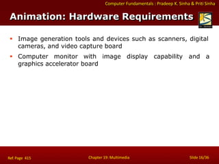
Category Valid Characters Total
Uppercase alphabets A, B, C, …, Z 26
Lowercase alphabets a, b, c, …, z 26
Digits 0, 1, 2, …, 9 10
Special characters
~ `!@ # % ^ & * ( ) _
| {}[ ] : ; " ' , . ? /
31
93](https://image.slidesharecdn.com/fundamentalbook2-240329013316-09ac5f4b/85/fundamental-of-computer-computer-what-about-computer-works-in-today-world-984-320.jpg)


![Computer Fundamentals : Pradeep K. Sinha & Priti Sinha
Operator Meaning with Example Associativity Precedence
Data Access Operators
x[y] Access yth element of array x; y starts
from zero and increases monotically up
to one less than declared size of array
L R 1
x.y Access the member variable y of
structure x
L R 1
x –›y Access the member variable y of
structure x
L R 1
&x Access the address of variable x R L 2
*x Access the value stored in the storage
location (address) pointed to by pointer
variable x
R L 2
Data Access Operators
Ref. Page 448 Chapter 21: Introduction to C Programming Languages Slide 25/76](https://image.slidesharecdn.com/fundamentalbook2-240329013316-09ac5f4b/85/fundamental-of-computer-computer-what-about-computer-works-in-today-world-1004-320.jpg)


![Computer Fundamentals : Pradeep K. Sinha & Priti Sinha
Array
Ref. Page 455 Chapter 21: Introduction to C Programming Languages Slide 43/76
An array is a collection of fixed number of elements in
which all elements are of the same data type
It is a homogeneous, linear, and contiguous memory
structure
Its elements can be referred to by using their subscript
or index position that is monotonic in nature
First element is always denoted by subscript value of 0
(zero), increasing monotonically up to one less than
declared size of array
Before using an array, its type and dimension must be
declared
An array can also be declared as multi-dimensional such
as Matrix2D[10][10]](https://image.slidesharecdn.com/fundamentalbook2-240329013316-09ac5f4b/85/fundamental-of-computer-computer-what-about-computer-works-in-today-world-1022-320.jpg)
![Computer Fundamentals : Pradeep K. Sinha & Priti Sinha
Illustrating Arrays Concept
Ref. Page 455 Chapter 21: Introduction to C Programming Languages Slide 44/76
1010
1008
1006
1004
1002
1000
int marks[6];
Each element
being an int
occupies 2 bytes
marks[0] = 45
marks[1] = 84
.
.
.
marks[5] = 92
(a) An array of
integers having
6 elements
float price[4];
Each element
being a float
occupies 4 bytes
price[0] = 82.75
price[1] = 155.50
.
.
price[3] = 10.25
(b) An array of
real numbers
having 4 elements
char city[6];
Each element
being a char
occupies 1 byte
city[0] = ‘B’
city[1] = ‘O’
.
..
.
city[5] = ‘Y’
(c) An array of
characters
having 6 elements
92
63
82
66
84
45
10.25
250.00
155.50
82.75
1012
1008
1004
1000
1005
1004
1003
1002
1001
1000
Y
A
B
M
O
B](https://image.slidesharecdn.com/fundamentalbook2-240329013316-09ac5f4b/85/fundamental-of-computer-computer-what-about-computer-works-in-today-world-1023-320.jpg)
![Computer Fundamentals : Pradeep K. Sinha & Priti Sinha
String
Ref. Page 455 Chapter 21: Introduction to C Programming Languages Slide 45/76
A string is a one-dimensional
terminated by a null character (‘0)’
array of characters
It is initialized at declaration as
char name[] = “PRADEEP”;
Its individual elements can be accessed in the same way
as we access array elements such as name[3] = ‘D’
Strings are used for text processing
C provides a rich set of string handling library functions](https://image.slidesharecdn.com/fundamentalbook2-240329013316-09ac5f4b/85/fundamental-of-computer-computer-what-about-computer-works-in-today-world-1024-320.jpg)


![Computer Fundamentals : Pradeep K. Sinha & Priti Sinha
struct Employee
{
int EmpID;
char EmpName[20];
} EmpRecord;
struct Employee
{
int EmpID;
char EmpName[20];
};
Struct Employee EmpRecord;
Struct Employee pempRecord = &EmpRecord;
Structure (Examples)
Ref. Page 457 Chapter 21: Introduction to C Programming Languages Slide 50/76](https://image.slidesharecdn.com/fundamentalbook2-240329013316-09ac5f4b/85/fundamental-of-computer-computer-what-about-computer-works-in-today-world-1029-320.jpg)


![Computer Fundamentals : Pradeep K. Sinha & Priti Sinha
Return [value/variable]: Causes immediate termination of
function in which it appears and
transfers control to the statement
that called the function. Optionally,
it provides a value compatible to
the function’s return data type.
Ref. Page 460 Chapter 21: Introduction to C Programming Languages Slide 60/76
Unconditional Branch Statements](https://image.slidesharecdn.com/fundamentalbook2-240329013316-09ac5f4b/85/fundamental-of-computer-computer-what-about-computer-works-in-today-world-1039-320.jpg)


![Computer Fundamentals : Pradeep K. Sinha & Priti Sinha
/ Program to accept a string from console and to display the number of
vowels in the string /
# include <stdio.h>
# include <conio.h>
# include <string.h>
void main()
{
char input_string[50]; / maximum 50 characters /
int len;
int i = 0, cnt = 0;
clrscr();
printf (“Enter a string of less than 50 characters: n”);
gets (input_string);
len = strlen (input_string);
for (i = 0; i < len; i++)
{
switch (input_string[i])
(Continued on next slide)
Sample C Program (Program-4)
Ref. Page 466 Chapter 21: Introduction to C Programming Languages Slide 73/76](https://image.slidesharecdn.com/fundamentalbook2-240329013316-09ac5f4b/85/fundamental-of-computer-computer-what-about-computer-works-in-today-world-1052-320.jpg)

![Computer Fundamentals : Pradeep K. Sinha & Priti Sinha
/ Program to illustrate use of a user defined function. The program initializes an array of n elements
from 0 to n-1 and then calculates and prints the sum of the array elements. In this example n = 10 /
#include <stdio.h>
#define SIZE 10
int ArrSum(int *p, int n);
{
int s, tot = 0;
for(s = 0; s < n; s++)
{
tot += *p;
p++;
}
return tot;
}
int main()
{
int i = 0, sum = 0;
int nArr[SIZE] = {0};
while(i < SIZE)
{
nArr[i] = i;
i++
}
sum = ArrSum(nArr, SIZE);
printf("Sum of 0 to 9 = %dn", sum);
return 0;
}
Sample C Program (Program-5)
Ref. Page 466 Chapter 21: Introduction to C Programming Languages Slide 75/76](https://image.slidesharecdn.com/fundamentalbook2-240329013316-09ac5f4b/85/fundamental-of-computer-computer-what-about-computer-works-in-today-world-1054-320.jpg)

fundamental of computer computer what about computer works in today world
- 1. Computer Fundamentals : Pradeep K. Sinha & Priti Sinha Chapter 01: Introduction Slide 1/17 Chapter 1 Introduction Computer Fundamentals Pradeep K. Sinha Priti Sinha
- 2. Computer Fundamentals : Pradeep K. Sinha & Priti Sinha Slide 2/17 Chapter 01: Introduction Learning Objectives In this chapter you will learn about: Computer Data processing Characteristic features of computers Computers’ evolution to their present form Computer generations Characteristic features of each computer generation
- 3. Computer Fundamentals : Pradeep K. Sinha & Priti Sinha The word computer comes from the word “compute”, which means, “to calculate” Thereby, a computer is an electronic device that can perform arithmetic operations at high speed A computer is also called a data processor because it can store, process, and retrieve data whenever desired Computer Ref. Page 01 Chapter 01: Introduction Slide 3/17
- 4. Computer Fundamentals : Pradeep K. Sinha & Priti Sinha Data Processing The activity of processing data using a computer is called data processing Data is raw material used as input to data processing and information is processed data obtained as output Data (Raw material) Information (Finished product) Computer (Data processor) Input Ref. Page 01 Chapter 01: Introduction Slide 4/17 Output
- 5. Computer Fundamentals : Pradeep K. Sinha & Priti Sinha Characteristics of Computers Ref. Page 01 Chapter 01: Introduction Slide 5/17 Sr. No. Characteristics Description 1 Automatic It carries out a job normally without any human intervention 2 Speed It can perform several billion (109) simple arithmetic operations per second 3 Accuracy It performs every calculation with the same accuracy 4 Diligence It is free from monotony, tiredness, and lack of concentration 5 Versatility It can perform a wide variety of tasks 6 Memory It can store huge amount of information and can recall any piece of this information whenever required 7 No I. Q. It cannot take its own decisions, and has to be instructed what to do and in what sequence 8 No Feelings It cannot make judgments based on feelings and instincts
- 6. Computer Fundamentals : Pradeep K. Sinha & Priti Sinha Chapter 01: Introduction Slide 6/17 Evolution of Computers
- 7. Computer Fundamentals : Pradeep K. Sinha & Priti Sinha Evolution of Computers Ref. Page 03 Chapter 01: Introduction Slide 7/17 Blaise Pascal invented the first mechanical adding machine in 1642 Baron Gottfried Wilhelm von Leibniz invented the first calculator for multiplication in 1671 Keyboard machines originated in the United States around 1880 Around 1880, Herman Hollerith came up with the concept of punched cards that were extensively used as input media until late 1970s (Continued on next slide)
- 8. Computer Fundamentals : Pradeep K. Sinha & Priti Sinha Charles Babbage is considered to be the father of modern digital computers He designed “Difference Engine” in 1822 He designed a fully automatic analytical engine in 1842 for performing basic arithmetic functions His efforts established a number of principles that are fundamental to the design of any digital computer Evolution of Computers Ref. Page 03 Chapter 01: Introduction Slide 8/17
- 9. Computer Fundamentals : Pradeep K. Sinha & Priti Sinha Some Well Known Early Computers Ref. Page 03 Chapter 01: Introduction Slide 9/17 The Mark I Computer (1937-44) The Atanasoff-Berry Computer (1939-42) The Electronic Numerical Integrator And Calculator (ENIAC) (1943-46) The Electronic Discrete Variable Automatic Computer (EDVAC) (1946-52) The Electronic Delay Storage Automatic Calculator (EDSAC) (1947-49) Manchester Mark I (1948) The Universal Automatic Computer (UNIVAC) I (1951) IBM 701 (1952) IBM 650 (1953)
- 10. Computer Fundamentals : Pradeep K. Sinha & Priti Sinha Chapter 01: Introduction Slide 10/17 Computer Generations
- 11. Computer Fundamentals : Pradeep K. Sinha & Priti Sinha Slide 11/17 Chapter 01: Introduction “Generation” in computer talk is a step in technology. It provides a framework for the growth of computer industry Originally it was used to distinguish between various hardware technologies, but now it has been extended to include both hardware and software Till today, there are five computer generations Computer Generations (Continued on next slide) Ref. Page 04
- 12. Slide 12/17 Chapter 01: Introduction Computer Fundamentals : Pradeep K. Sinha & Priti Sinha Computer Generations Generation (Period) Key hardware technologies Key software technologies Key characteristics Some representative systems First (1942-1955) • Vacuum tubes •Electromagnetic relay memory • Punched cards secondary storage Machine and assembly languages Stored program concept Mostly scientific applications Bulky in size Highly unreliable Limited commercial use commercial production difficult and costly Difficult to use ENIAC EDVAC EDSAC UNIVAC I IBM 701 Second (1955-1964) Transistors Magnetic core memory Magnetic tapes Disks secondary storage Batch operating system High-level programming languages Scientific and commercial applications Faster, smaller, more reliable and easier to program than previous generation systems Commercial production was still difficult and costly Honeywell 400 IBM 7030 CDC 1604 UNIVAC LARC
- 13. Computer Fundamentals : Pradeep K. Sinha & Priti Sinha Computer Generations Ref. Page 15 Chapter 01: Introduction Slide 13/17 (Continued on next slide) Generation (Period) Key hardware technologies Key software technologies Key Characteristics Some representative systems Third (1964-1975) ICs with SSI and MSI technologies Larger magnetic core memory Larger capacity magnetic disks and tapes secondary storage Minicomputers Timesharing operating system Standardization of high-level programming languages Unbundling of software from hardware Faster, smaller, more reliable, easier and cheaper to produce Commercially, easier to use, and easier to upgrade than previous generation systems Scientific, commercial and interactive on-line applications IBM 360/370 PDP-8 PDP-11 CDC 6600
- 14. Computer Fundamentals : Pradeep K. Sinha & Priti Sinha Computer Generations Ref. Page 15 Chapter 01: Introduction Slide 14/17 Generation (Period) Key hardware technologies Key software technologies Key Characteristics Some representative systems Fourth (1975-1989) ICs with VLSI technology Microprocessors; semiconductor memory Larger capacity hard disks as in- built secondary storage Magnetic tapes and floppy disks as portable storage media Personal computers Spread of high- speed computer networks Operating systems for PCs with GUI and Multiple windows on a single terminal screen Multiprocessor operating systems and concurrent programming languages UNIX operating system C and C++ programming languages PC-based applications; network-based applications Object-oriented software design Small, affordable, reliable, and easy to use PCs More powerful and reliable mainframe systems General purpose machines Easier to produce commercially (Con IBM PC and its clones Apple II TRS-80 VAX 9000 CRAY-1 CRAY-2 CRAY-X/MP tinued on next slide)
- 15. Computer Fundamentals : Pradeep K. Sinha & Priti Sinha Computer Generations Ref. Page 15 Chapter 01: Introduction Slide 15/17 (Continued on next slide) Generation (Period) Key hardware technologies Key software technologies Key Characteristics Some representative systems Fifth (1989- Present) ICs with ULSI technology Multicore processor chips Larger capacity main memory and hard disks Optical disks as portable read-only storage media Solid state disks Notebook computers Powerful desktop PCs and workstations Very powerful mainframes Supercomputers based on parallel processing Internet World Wide Web Multimedia, Internet-based applications Microkernel, multithreading, multicore OS JAVA, Python and other programming languages MPI and PVM libraries for parallel programming Portable computers Hand-held mobile smart devices More powerful, cheaper, reliable, and easier to use desktop machines Very powerful mainframes Very high uptime due to hot-pluggable components General purpose machines Easier to produce commercially iPhone iPad IBM notebooks Pentium PCs Windows PC Apple PC SUN Workstations IBM SP/2 SGI Origin 2000 PARAM supercomputers
- 16. Computer Fundamentals : Pradeep K. Sinha & Priti Sinha Electronic Devices Used in Computers of Different Generations (c) An IC chip (b) A Transistor (a) A Vacuum tube Ref. Page 15 Chapter 01: Introduction Slide 16/17
- 17. Computer Fundamentals : Pradeep K. Sinha & Priti Sinha Key Words/Phrases Chapter 01: Introduction Slide 17/17 Computer Computer generations Computer Supported Cooperative Working (CSCW) Data Data processing Data processor First-generation computers Second-generation computers Third-generation computers Fourth-generation computers Fifth-generation computers Garbage-in-garbage-out (GIGO) Graphical User Interface (GUI) Groupware Information Integrated Circuit (IC) Large Scale Integration (VLSI) Medium Scale Integration (MSI) Microprocessor Personal Computer (PC) Second-generation computers Small Scale Integration (SSI) Stored program concept Third-generation computers Transistor Ultra Large Scale Integration (ULSI) Vacuum tubes
- 18. Computer Fundamentals: Pradeep K. Sinha & Priti Sinha Chapter 02: Basic Computer Organization Slide 1/19 Pradeep K. Sinha Priti Sinha Chapter 2 Basic Computer Organization Computer Fundamentals
- 19. Computer Fundamentals: Pradeep K. Sinha & Priti Sinha In this chapter you will learn about: Basic operations performed by all types of computer systems Basic organization of a computer system Input unit and its functions Output unit and its functions Storage unit and its functions Types of storage used in a computer system Learning Objectives Chapter 02: Basic Computer Organization Slide 2/19 (Continued on next slide)
- 20. Computer Fundamentals: Pradeep K. Sinha & Priti Sinha Arithmetic Logic Unit (ALU) Control Unit (CU) Central Processing Unit (CPU) Computer as a system Learning Objectives Chapter 02: Basic Computer Organization Slide 3/19
- 21. Computer Fundamentals: Pradeep K. Sinha & Priti Sinha Inputting. The process of entering data and instructions into the computer system Storing. Saving data readily available for whenever required and instructions to make them initial or additional processing Processing. Performing arithmetic operations (add, subtract, multiply, divide, etc.) or logical operations (comparisons like equal to, less than, greater than, etc.) on data to convert them into useful information The Five Basic Operations of a Computer System Ref. Page 18 Chapter 02: Basic Computer Organization Slide 4/19 (Continued on next slide)
- 22. Computer Fundamentals: Pradeep K. Sinha & Priti Sinha Outputting. The process of producing useful information or results for the user such as a printed report or visual display Controlling. Directing the manner and sequence in which all of the above operations are performed The Five Basic Operations of a Computer System Ref. Page 18 Chapter 02: Basic Computer Organization Slide 5/19
- 23. Computer Fundamentals: Pradeep K. Sinha & Priti Sinha Central Processing Unit (CPU) Storage Unit Secondary Storage Primary Storage Control Unit Arithmetic Logic Unit Input Unit Output Unit Program and Data Information (Results) Indicates flow of instructions and data Indicates the control exercised by the control unit Basic Organization of a Computer System Ref. Page 18 Chapter 02: Basic Computer Organization Slide 6/19
- 24. Computer Fundamentals: Pradeep K. Sinha & Priti Sinha Chapter 02: Basic Computer Organization Slide 7/19 Main Units and Their Functions
- 25. Computer Fundamentals: Pradeep K. Sinha & Priti Sinha An input unit of a computer system performs the following functions: 1. It accepts (or reads) instructions and data from outside world 2. It converts these instructions and data in computer acceptable form 3. It supplies the converted instructions and data to the computer system for further processing Input Unit Ref. Page 20 Chapter 02: Basic Computer Organization Slide 8/19
- 26. Computer Fundamentals: Pradeep K. Sinha & Priti Sinha An output unit of a computer system performs the following functions: 1. It accepts the results produced by the computer, which are in coded form and hence, cannot be easily understood by us 2. It converts these coded results to human acceptable (readable) form 3. It supplies the converted results to outside world Output Unit Ref. Page 20 Chapter 02: Basic Computer Organization Slide 9/19
- 27. Computer Fundamentals: Pradeep K. Sinha & Priti Sinha The storage unit of a computer system holds (or stores) the following : 1. Data and instructions required for processing (received from input devices) 2. Intermediate results of processing 3. Final results of processing, before they are released to an output device Storage Unit Ref. Page 20 Chapter 02: Basic Computer Organization Slide 10/19
- 28. Computer Fundamentals: Pradeep K. Sinha & Priti Sinha The broad categories of storage are: 1. Primary storage 2. Secondary storage Types of Storage Ref. Page 20 Chapter 02: Basic Computer Organization Slide 11/19
- 29. Computer Fundamentals: Pradeep K. Sinha & Priti Sinha Used to hold running program instructions Used to hold data, intermediate results, and results of ongoing processing of job(s) Fast in operation Small Capacity Expensive Volatile (looses data on power dissipation) Primary Storage Ref. Page 20 Chapter 02: Basic Computer Organization Slide 12/19 (Continued on next slide)
- 30. Computer Fundamentals: Pradeep K. Sinha & Priti Sinha Used to hold stored program instructions Used to hold data and information of stored jobs Slower than primary storage Large Capacity Lot cheaper that primary storage Retains data even without power Secondary Storage Ref. Page 20 Chapter 02: Basic Computer Organization Slide 13/19
- 31. Computer Fundamentals: Pradeep K. Sinha & Priti Sinha Arithmetic Logic Unit of a computer system is the place where the actual executions of instructions takes place during processing operation Arithmetic Logic Unit (ALU) Ref. Page 20 Chapter 02: Basic Computer Organization Slide 14/19
- 32. Computer Fundamentals: Pradeep K. Sinha & Priti Sinha Control Unit of a computer system manages and coordinates the operations of all other components of the computer system Control Unit (CU) Ref. Page 20 Chapter 02: Basic Computer Organization Slide 15/19
- 33. Computer Fundamentals: Pradeep K. Sinha & Priti Sinha Arithmetic Logic Unit (ALU) Control Unit (CU) = Central Processing Unit (CPU) It is the brain of a computer system It is responsible for controlling the operations of all other units of a computer system + Central Processing Unit (CPU) Ref. Page 20 Chapter 02: Basic Computer Organization Slide 16/19
- 34. Computer Fundamentals: Pradeep K. Sinha & Priti Sinha Chapter 02: Basic Computer Organization Slide 17/19 The System Concept
- 35. Slide 18/19 Chapter 02: Basic Computer Organization Computer Fundamentals: Pradeep K. Sinha & Priti Sinha A system has following three characteristics: 1. A system has more than one element 2. All elements of a system are logically related 3. All elements of a system are controlled in a manner to achieve the system goal A computer is a system as it comprises of integrated components (input unit, output unit, storage unit, and CPU) that work together to perform the steps called for in the executing program The System Concept Ref. Page 21
- 36. Slide 19/19 Chapter 02: Basic Computer Organization Computer Fundamentals: Pradeep K. Sinha & Priti Sinha Arithmetic Logic Unit (ALU) Auxiliary storage Central Processing Unit (CPU) Computer system Control Unit (CU) Controlling Input interface Input unit Inputting Main memory Output interface Output unit Outputting Primate storage Processing Secondary storage Storage unit Storing System Key Words/Phrases
- 37. Computer Fundamentals : Pradeep K. Sinha & Priti Sinha Chapter 03: Number Systems Slide 1/43 Chapter 3 Number Systems Computer Fundamentals Pradeep K. Sinha Priti Sinha
- 38. Computer Fundamentals : Pradeep K. Sinha & Priti Sinha In this chapter you will learn about: Non-positional number system Positional number system Decimal number system Binary number system Octal number system Hexadecimal number system Learning Objectives Chapter 03: Number Systems Slide 2/43 (Continued on next slide)
- 39. Computer Fundamentals : Pradeep K. Sinha & Priti Sinha Convert a number’s base Another base to decimal base Decimal base to another base Some base to another base Shortcut methods for converting Binary to octal number Octal to binary number Binary to hexadecimal number Hexadecimal to binary number Fractional numbers in binary number system Learning Objectives Chapter 03: Number Systems Slide 3/43
- 40. Computer Fundamentals : Pradeep K. Sinha & Priti Sinha Two types of number systems are: Non-positional number systems Positional number systems Number Systems Ref. Page 23 Chapter 03: Number Systems Slide 4/43
- 41. Computer Fundamentals : Pradeep K. Sinha & Priti Sinha Chapter 03: Number Systems Slide 5/43 Basics and Few Popular Number Systems
- 42. Computer Fundamentals : Pradeep K. Sinha & Priti Sinha Characteristics Use symbols such as I for 1, II for 2, III for 3, IIII for 4, IIIII for 5, etc Each symbol represents the same value regardless of its position in the number The symbols are simply added to find out the value of a particular number Difficulty It is difficult to perform arithmetic with such a number system Non-positional Number Systems Ref. Page 23 Chapter 03: Number Systems Slide 6/43
- 43. Computer Fundamentals : Pradeep K. Sinha & Priti Sinha Characteristics Use only a few symbols called digits These symbols represent different values depending on the position they occupy in the number Positional Number Systems Ref. Page 24 Chapter 03: Number Systems Slide 7/43 (Continued on next slide)
- 44. Computer Fundamentals : Pradeep K. Sinha & Priti Sinha The value of each digit is determined by: 1. The digit itself 2. The position of the digit in the number 3. The base of the number system (base = total number of digits in the number system) The maximum value of a single digit is always equal to one less than the value of the base Positional Number Systems Ref. Page 24 Chapter 03: Number Systems Slide 8/43
- 45. Computer Fundamentals : Pradeep K. Sinha & Priti Sinha Characteristics A positional number system Has 10 symbols or digits (0, 1, 2, 3, 4, 5, 6, 7, 8, 9). Hence, its base = 10 The maximum value of a single digit is 9 (one less than the value of the base) Each position of a digit represents a specific power of the base (10) We use this number system in our day-to-day life Decimal Number System Ref. Page 24 Chapter 03: Number Systems Slide 9/43 (Continued on next slide)
- 46. Computer Fundamentals : Pradeep K. Sinha & Priti Sinha Example 258610 = (2 x 10³) + (5 x 10²) + (8 x 101) + (6 x 100) = 2000 + 500 + 80 + 6 Decimal Number System Ref. Page 24 Chapter 03: Number Systems Slide 10/43
- 47. Computer Fundamentals : Pradeep K. Sinha & Priti Sinha Characteristics A positional number system Has only 2 symbols or digits (0 and 1). base = 2 Hence its The maximum value of a single digit is 1 (one less than the value of the base) Each position of a digit represents a specific power of the base (2) This number system is used in computers Binary Number System Ref. Page 24 Chapter 03: Number Systems Slide 11/43 (Continued on next slide)
- 48. Computer Fundamentals : Pradeep K. Sinha & Priti Sinha Example 101012 = (1 x 24) + (0 x 23) + (1 x 22) + (0 x 21) x (1 x 20) = 16 + 0 + 4 + 0 + 1 = 2110 Binary Number System Ref. Page 24 Chapter 03: Number Systems Slide 12/43
- 49. Computer Fundamentals : Pradeep K. Sinha & Priti Sinha In order to be specific about which number system we are referring to, it is a common practice to indicate the base as a subscript. Thus, we write: 101012 = 2110 Representing Numbers in Different Number Systems Ref. Page 24 Chapter 03: Number Systems Slide 13/43
- 50. Computer Fundamentals : Pradeep K. Sinha & Priti Sinha Bit stands for binary digit A bit in computer terminology means either a 0 or a 1 A binary number consisting of n bits is called an n-bit number Bit Ref. Page 24 Chapter 03: Number Systems Slide 14/43
- 51. Computer Fundamentals : Pradeep K. Sinha & Priti Sinha Characteristics A positional number system Has total 8 symbols or digits (0, 1, 2, 3, 4, 5, 6, 7). Hence, its base = 8 The maximum value of a single digit is 7 (one less than the value of the base Each position of a digit represents a specific power of the base (8) Octal Number System Ref. Page 24 Chapter 03: Number Systems Slide 15/43 (Continued on next slide)
- 52. Computer Fundamentals : Pradeep K. Sinha & Priti Sinha Since there are only 8 digits, 3 bits (23 = 8) are sufficient to represent any octal number in binary Example 20578 = (2 x 83) + (0 x 82) + (5 x 81) + (7 x 80) = 1024 + 0 + 40 + 7 = 107110 Octal Number System Ref. Page 24 Chapter 03: Number Systems Slide 16/43
- 53. Computer Fundamentals : Pradeep K. Sinha & Priti Sinha Characteristics A positional number system Has total 16 symbols or digits (0, 1, 2, 3, 4, 5, 6, 7, 8, 9, A, B, C, D, E, F). Hence its base = 16 The symbols A, B, C, D, E and F represent the decimal values 10, 11, 12, 13, 14 and 15 respectively The maximum value of a single digit is 15 (one less than the value of the base) Hexadecimal Number System Ref. Page 24 Chapter 03: Number Systems Slide 17/43 (Continued on next slide)
- 54. Computer Fundamentals : Pradeep K. Sinha & Priti Sinha Each position of a digit represents a specific power of the base (16) Since there are only 16 digits, 4 bits (24 = 16) are sufficient to represent any hexadecimal number in binary Example 1AF16 = (1 x 162) + (A x 161) + (F x 160) = 1 x 256 + 10 x 16 + 15 x 1 = 256 + 160 + 15 = 43110 Hexadecimal Number System Ref. Page 24 Chapter 03: Number Systems Slide 18/43
- 55. Computer Fundamentals : Pradeep K. Sinha & Priti Sinha Chapter 03: Number Systems Slide 19/43 Converting from One Number System to Another
- 56. Computer Fundamentals : Pradeep K. Sinha & Priti Sinha Method Step 1: Determine the column (positional) value of each digit Step 2: Multiply the obtained column values by the digits in the corresponding columns Step 3: Calculate the sum of these products Converting a Number of Another Base to a Decimal Number Ref. Page 26 Chapter 03: Number Systems Slide 20/43 (Continued on next slide)
- 57. Computer Fundamentals : Pradeep K. Sinha & Priti Sinha 47068 = 4 x 83 + 7 x 82 + 0 x 81 + 6 x 80 = 4 x 512 + 7 x 64 + 0 + 6 x 1 = 2048 + 448 + 0 + 6 = 250210 Example 47068 = ?10 Column values multiplied by the corresponding digits Sum of these products Converting a Number of Another Base to a Decimal Number Ref. Page 26 Chapter 03: Number Systems Slide 21/43
- 58. Computer Fundamentals : Pradeep K. Sinha & Priti Sinha Division-Remainder Method Step 1: Divide the decimal number to be converted by the value of the new base Step 2: Record the remainder from Step 1 as the rightmost digit (least significant digit) of the new base number Divide the quotient of the previous divide by the new base Step 3: Converting a Decimal Number to a Number of Another Base Ref. Page 26 Chapter 03: Number Systems Slide 22/43 (Continued on next slide)
- 59. Computer Fundamentals : Pradeep K. Sinha & Priti Sinha Step 4: Record the remainder from Step 3 as the next digit (to the left) of the new base number Repeat Steps 3 and 4, recording remainders from right to left, until the quotient becomes zero in Step 3 Note that the last remainder thus obtained will be the most significant digit (MSD) of the new base number (Continued on next slide) Converting a Decimal Number to a Number of Another Base Ref. Page 26 Chapter 03: Number Systems Slide 23/43
- 60. Computer Fundamentals : Pradeep K. Sinha & Priti Sinha Example 95210 = ?8 Solution: 0 8 952 Remainders 119 0 14 7 1 6 1 Hence, 95210 = 16708 Converting a Decimal Number to a Number of Another Base Ref. Page 26 Chapter 03: Number Systems Slide 24/43
- 61. Computer Fundamentals : Pradeep K. Sinha & Priti Sinha Method Step 1: Convert the original number to a decimal number (base 10) Step 2: Convert the decimal number so obtained to the new base number (Continued on next slide) Converting from a Base Other Than 10 to Another Base Other Than 10 Ref. Page 26 Chapter 03: Number Systems Slide 25/43
- 62. Computer Fundamentals : Pradeep K. Sinha & Priti Sinha Example 5456 = ?4 Solution: Step 1: Convert from base 6 to base 10 5456 = 5 x 62 + 4 x 61 + 5 x 60 = 5 x 36 + 4 x 6 + 5 x 1 = 180 + 24 + 5 = 20910 (Continued on next slide) Converting from a Base Other Than 10 to Another Base Other Than 10 Ref. Page 26 Chapter 03: Number Systems Slide 26/43
- 63. Computer Fundamentals : Pradeep K. Sinha & Priti Sinha Step 2: Convert 20910 to base 4 Hence, 20910 = 31014 So, 5456 = 20910 = 31014 Thus, 5456 = 31014 Remainders 1 0 1 3 209 52 13 3 0 4 Converting from a Base Other Than 10 to Another Base Other Than 10 Ref. Page 26 Chapter 03: Number Systems Slide 27/43
- 64. Computer Fundamentals : Pradeep K. Sinha & Priti Sinha Method Step 1: Divide the digits into groups of three starting from the right Step 2: Convert each group of three binary digits to one octal digit using the method of binary to decimal conversion Shortcut Method for Converting a Binary Number to its Equivalent Octal Number Ref. Page 26 Chapter 03: Number Systems Slide 28/43 (Continued on next slide)
- 65. Computer Fundamentals : Pradeep K. Sinha & Priti Sinha Example 11010102 = ?8 Step 1: Divide the binary digits into groups of 3 starting from right 001 101 010 Step 2: Convert each group into one octal digit 0012 = 0 x 22 + 0 x 21 + 1 x 20 = 1 1012 = 1 x 22 + 0 x 21 + 1 x 20 = 5 0102 = 0 x 22 + 1 x 21 + 0 x 20 = 2 Hence, 11010102 = 1528 Shortcut Method for Converting a Binary Number to its Equivalent Octal Number Ref. Page 26 Chapter 03: Number Systems Slide 29/43
- 66. Computer Fundamentals : Pradeep K. Sinha & Priti Sinha Method Step 1: Convert each octal digit to a 3 digit binary number (the octal digits may be treated as decimal for this conversion) binary single groups binary (of 3 digits Step 2: Combine all the resulting each) into a number Shortcut Method for Converting an Octal Number to Its Equivalent Binary Number Ref. Page 26 Chapter 03: Number Systems Slide 30/43 (Continued on next slide)
- 67. Computer Fundamentals : Pradeep K. Sinha & Priti Sinha Example 5628 = ?2 Step 1: Convert each octal digit to 3 binary digits 58 = 1012, 68 = 1102, 28 = 0102 Step 2: Combine the binary groups 5628 = 101 110 010 5 6 2 Hence, 5628 = 1011100102 Shortcut Method for Converting an Octal Number to Its Equivalent Binary Number Ref. Page 26 Chapter 03: Number Systems Slide 31/43
- 68. Computer Fundamentals : Pradeep K. Sinha & Priti Sinha Method Step 1: Ref. Page 26 Chapter 03: Number Systems Slide 32/43 Divide the binary digits into groups of four starting from the right Combine each group of four binary digits to one hexadecimal digit Step 2: Shortcut Method for Converting a Binary Number to its Equivalent Hexadecimal Number (Continued on next slide)
- 69. Computer Fundamentals : Pradeep K. Sinha & Priti Sinha Example Ref. Page 26 Chapter 03: Number Systems Slide 33/43 1111012 = ?16 Step 1: Divide the binary digits into groups of four starting from the right 0011 1101 Step 2: Convert each group into a hexadecimal digit 00112 = 0 x 23 + 0 x 22 + 1 x 21 + 1 x 20 = 310 = 316 11012 = 1 x 23 + 1 x 22 + 0 x 21 + 1 x 20 = 310 = D16 Hence, 1111012 = 3D16 Shortcut Method for Converting a Binary Number to its Equivalent Hexadecimal Number
- 70. Computer Fundamentals : Pradeep K. Sinha & Priti Sinha Method Step 1: Convert the decimal equivalent of each hexadecimal digit to a 4 digit binary number Step 2: Combine all the resulting binary groups (of 4 digits each) in a single binary number Ref. Page 34 Chapter 03: Number Systems Slide 34/43 Shortcut Method for Converting a Hexadecimal Number to its Equivalent Binary Number (Continued on next slide)
- 71. Computer Fundamentals : Pradeep K. Sinha & Priti Sinha Shortcut Method for Converting a Hexadecimal Number to its Equivalent Binary Number Example 2AB16 = ?2 Step 1: Convert each hexadecimal digit to a 4 digit binary number Ref. Page 35 Chapter 03: Number Systems Slide 34/43 216 = 210 = 00102 A16 = 1010 = 10102 B16 = 1110 = 10112
- 72. Computer Fundamentals : Pradeep K. Sinha & Priti Sinha Step 2: Combine the binary groups Ref. Page 36 Chapter 03: Number Systems Slide 34/43 2AB16 = 0010 1010 1011 2 A B Hence, 2AB16 = 0010101010112 Shortcut Method for Converting a Hexadecimal Number to its Equivalent Binary Number
- 73. Computer Fundamentals : Pradeep K. Sinha & Priti Sinha Chapter 03: Number Systems Slide 37/43 Fractional Numbers
- 74. Computer Fundamentals : Pradeep K. Sinha & Priti Sinha Fractional Numbers Ref. Page 35 Chapter 03: Number Systems Slide 38/43 Fractional numbers are formed same way as decimal number system In general, a number in a number system with base b would be written as: an an-1… a0 . a-1 a-2 … a-m And would be interpreted to mean: an x bn + an-1 x bn-1 + … + a0 x b0 + a-1 x b-1 + a-2 x b-2 + … + a-m x b-m The symbols an, an-1, a-m …, in above representation should be one of the b symbols allowed in the number system
- 75. Computer Fundamentals : Pradeep K. Sinha & Priti Sinha Formation of Fractional Numbers in Binary Number System (Example) Position Position Value 4 3 2 1 0 . -1 -2 -3 -4 24 23 22 21 20 2-1 2-2 2-3 2-4 Quantity Represented 16 8 4 2 1 1/2 1/4 1/8 1/16 Binary Point (Continued on next slide) Ref. Page 35 Chapter 03: Number Systems Slide 39/43
- 76. Computer Fundamentals : Pradeep K. Sinha & Priti Sinha Example 110.1012 = 1 x 22 + 1 x 21 + 0 x 20 + 1 x 2-1 + 0 x 2-2 + 1 x 2-3 = 4 + 2 + 0 + 0.5 + 0 + 0.125 = 6.62510 Formation of Fractional Numbers in Binary Number System (Example) Ref. Page 35 Chapter 03: Number Systems Slide 40/43
- 77. Computer Fundamentals : Pradeep K. Sinha & Priti Sinha Position 3 2 1 0 . -1 -2 -3 Position Value 83 82 81 80 8-1 8-2 8-3 Quantity Represented 512 64 8 1 1/8 1/64 1/512 Octal Point Formation of Fractional Numbers in Octal Number System (Example) Ref. Page 35 Chapter 03: Number Systems Slide 41/43 (Continued on next slide)
- 78. Computer Fundamentals : Pradeep K. Sinha & Priti Sinha Example 127.548 = 1 x 82 + 2 x 81 + 7 x 80 + 5 x 8-1 + 4 x 8-2 = 64 + 16 + 7 + 5/8 + 4/64 = 87 + 0.625 + 0.0625 = 87.687510 Formation of Fractional Numbers in Octal Number System (Example) Ref. Page 35 Chapter 03: Number Systems Slide 42/43
- 79. Computer Fundamentals : Pradeep K. Sinha & Priti Sinha Key Words/Phrases Chapter 03: Number Systems Slide 43/43 Base Binary number system Binary point Bit Decimal number system Division-Remainder technique Fractional numbers Hexadecimal number system Least Significant Digit (LSD) Memory dump Most Significant Digit (MSD) Non-positional number system Number system Octal number system Positional number system
- 80. Computer Fundamentals : Pradeep K. Sinha & Priti Sinha Chapter 04: Computer Codes Slide 1/36 Chapter 4 Computer Codes Computer Fundamentals Pradeep K. Sinha Priti Sinha
- 81. Computer Fundamentals : Pradeep K. Sinha & Priti Sinha Slide 2/36 Chapter 04: Computer Codes In this chapter you will learn about: Computer data Computer codes: representation of data in binary Most commonly used computer codes Collating sequence Learning Objectives
- 82. Computer Fundamentals : Pradeep K. Sinha & Priti Sinha Chapter 04: Computer Codes Slide 3/36 Data Types and Their Binary Representation
- 83. Computer Fundamentals : Pradeep K. Sinha & Priti Sinha Numeric Data consists of only numbers 0, 1, 2, …, 9 Alphabetic Data consists of only the letters A, B, C, …, Z, in both uppercase and lowercase, and blank character Alphanumeric Data is a string of symbols where a symbol may be one of the letters A, B, C, …, Z, in either uppercase or lowercase, or one of the digits 0, 1, 2, …, 9, or a special character, such as + - * / , . ( ) = etc. Data Types Ref. Page 38 Chapter 04: Computer Codes Slide 4/36
- 84. Computer Fundamentals : Pradeep K. Sinha & Priti Sinha Computer codes are used for internal representation of data in computers As computers use binary representation, computer schemes numbers for internal data codes use binary coding In binary coding, every symbol that appears in the data is represented by a group of bits The group of bits used to represent a symbol is called a byte Computer Codes Ref. Page 38 Chapter 04: Computer Codes Slide 5/36 (Continued on next slide)
- 85. Computer Fundamentals : Pradeep K. Sinha & Priti Sinha As most modern coding schemes use 8 bits to represent a symbol, the term byte is often used to mean a group of 8 bits Commonly used computer codes are BCD, EBCDIC, and ASCII Computer Codes Ref. Page 38 Chapter 04: Computer Codes Slide 6/36
- 86. Computer Fundamentals : Pradeep K. Sinha & Priti Sinha Chapter 04: Computer Codes Slide 7/36 BCD
- 87. Computer Fundamentals : Pradeep K. Sinha & Priti Sinha BCD stands for Binary Coded Decimal It is one of the early computer codes It uses 6 bits to represent a symbol It can represent 64 (26) different characters BCD Ref. Page 39 Chapter 04: Computer Codes Slide 8/36
- 88. Computer Fundamentals : Pradeep K. Sinha & Priti Sinha Char BCD Code Octal Zone Digit A 11 0001 61 B 11 0010 62 C 11 0011 63 D 11 0100 64 E 11 0101 65 F 11 0110 66 G 11 0111 67 H 11 1000 70 I 11 1001 71 J 10 0001 41 K 10 0010 42 L 10 0011 43 M 10 0100 44 Char BCD Code Octal Zone Digit N 10 0101 45 O 10 0110 46 P 10 0111 47 Q 10 1000 50 R 10 1001 51 S 01 0010 22 T 01 0011 23 U 01 0100 24 V 01 0101 25 W 01 0110 26 X 01 0111 27 Y 01 1000 30 Z 01 1001 31 Coding of Alphabetic and Numeric Characters in BCD Ref. Page 40 Chapter 04: Computer Codes Slide 9/36 (Continued on next slide)
- 89. Computer Fundamentals : Pradeep K. Sinha & Priti Sinha Character BCD Code Octal Equivalent Zone Digit 1 00 0001 01 2 00 0010 02 3 00 0011 03 4 00 0100 04 5 00 0101 05 6 00 0110 06 7 00 0111 07 8 00 1000 10 9 00 1001 11 0 00 0000 00 Coding of Alphabetic and Numeric Characters in BCD Ref. Page 40 Chapter 04: Computer Codes Slide 10/36
- 90. Computer Fundamentals : Pradeep K. Sinha & Priti Sinha Example Show the binary digits used to record the word BASE in BCD Solution: B = 110010 in BCD binary notation A = 110001 in BCD binary notation S = 010010 in BCD binary notation E = 110101 in BCD binary notation So the binary digits 110010 110001 010010 110101 B A S E will record the word BASE in BCD BCD Coding Scheme (Example 1) Ref. Page 40 Chapter 04: Computer Codes Slide 11/36
- 91. Computer Fundamentals : Pradeep K. Sinha & Priti Sinha Example Using octal notation, show BCD coding for the word DIGIT Solution: D = 64 in BCD octal notation I = 71 in BCD octal notation G = 67 in BCD octal notation I = 71 in BCD octal notation T = 23 in BCD octal notation Hence, BCD coding for the word DIGIT in octal notation will be Ref. Page 40 Chapter 04: Computer Codes Slide 12/36 64 71 67 71 23 D I G I T BCD Coding Scheme (Example 2)
- 92. Computer Fundamentals : Pradeep K. Sinha & Priti Sinha Chapter 04: Computer Codes Slide 13/36 EBCDIC
- 93. Computer Fundamentals : Pradeep K. Sinha & Priti Sinha EBCDIC stands for Extended Binary Coded Decimal Interchange Code It uses 8 bits to represent a symbol It can represent 256 (28) different characters EBCDIC Ref. Page 40 Chapter 04: Computer Codes Slide 14/36
- 94. Computer Fundamentals : Pradeep K. Sinha & Priti Sinha Char EBCDIC Code Hex Digit Zone A 1100 0001 C1 B 1100 0010 C2 C 1100 0011 C3 D 1100 0100 C4 E 1100 0101 C5 F 1100 0110 C6 G 1100 0111 C7 H 1100 1000 C8 I 1100 1001 C9 J 1101 0001 D1 K 1101 0010 D2 L 1101 0011 D3 M 1101 0100 D4 Char EBCDIC Code Hex Digit Zone N 1101 0101 D5 O 1101 0110 D6 P 1101 0111 D7 Q 1101 1000 D8 R 1101 1001 D9 S 1110 0010 E2 T 1110 0011 E3 U 1110 0100 E4 V 1110 0101 E5 W 1110 0110 E6 X 1110 0111 E7 Y 1110 1000 E8 Z 1110 1001 E9 Coding of Alphabetic and Numeric Characters in EBCDIC Ref. Page 41 Chapter 04: Computer Codes Slide 15/36 (Continued on next slide)
- 95. Computer Fundamentals : Pradeep K. Sinha & Priti Sinha Character EBCDIC Code Hexadecimal Equivalent Digit Zone 0 1111 0000 F0 1 1111 0001 F1 2 1111 0010 F2 3 1111 0011 F3 4 1111 0100 F4 5 1111 0101 F5 6 1111 0110 F6 7 1111 0111 F7 8 1111 1000 F8 9 1111 1001 F9 Coding of Alphabetic and Numeric Characters in EBCDIC Ref. Page 41 Chapter 04: Computer Codes Slide 16/36
- 96. Computer Fundamentals : Pradeep K. Sinha & Priti Sinha Zoned decimal numbers are used to represent numeric values (positive, negative, or unsigned) in EBCDIC A sign indicator (C for plus, D for minus, and F for unsigned) is used in the zone position of the rightmost digit Zones for all other digits remain as F , the zone value for numeric characters in EBCDIC In zoned format, there is only one digit per byte Zoned Decimal Numbers Ref. Page 41 Chapter 04: Computer Codes Slide 17/36
- 97. Computer Fundamentals : Pradeep K. Sinha & Priti Sinha Numeric Value EBCDIC Sign Indicator 345 F3F4F5 F for unsigned +345 F3F4C5 C for positive -345 F3F4D5 D for negative Examples Zoned Decimal Numbers Ref. Page 41 Chapter 04: Computer Codes Slide 18/36
- 98. Computer Fundamentals : Pradeep K. Sinha & Priti Sinha Packed decimal numbers are formed from zoned decimal numbers in the following manner: Step 1: The zone half and the digit half of the rightmost byte are reversed Step 2: All remaining zones are dropped out Packed decimal format requires fewer number of bytes than zoned decimal format for representing a number Numbers represented in packed decimal format can be used for arithmetic operations Packed Decimal Numbers Ref. Page 41 Chapter 04: Computer Codes Slide 19/36
- 99. Computer Fundamentals : Pradeep K. Sinha & Priti Sinha Numeric Value EBCDIC Sign Indicator 345 F3F4F5 345F +345 F3F4C5 345C -345 F3F4D5 345D 3456 F3F4F5F6 03456F Ref. Page 41 Chapter 04: Computer Codes Slide 20/36 Examples of Conversion of Zoned Decimal Numbers to Packed Decimal Format
- 100. Computer Fundamentals : Pradeep K. Sinha & Priti Sinha Example Using binary notation, write EBCDIC coding for the word BIT . How many bytes are required for this representation? Solution: B = 1100 0010 in EBCDIC binary notation I = 1100 1001 in EBCDIC binary notation T = 1110 0011 in EBCDIC binary notation Hence, EBCDIC coding for the word BIT in binary notation will be 11000010 11001001 11100011 B I T 3 bytes will be required for this representation because each letter requires 1 byte (or 8 bits) EBCDIC Coding Scheme Ref. Page 41 Chapter 04: Computer Codes Slide 21/36
- 101. Computer Fundamentals : Pradeep K. Sinha & Priti Sinha Chapter 04: Computer Codes Slide 22/36 ASCII
- 102. Computer Fundamentals : Pradeep K. Sinha & Priti Sinha ASCII stands for American Standard Code for Information Interchange. ASCII is of two types – ASCII-7 and ASCII-8 ASCII-7 uses 7 bits to represent a symbol and can represent 128 (27) different characters ASCII-8 uses 8 bits to represent a symbol and can represent 256 (28) different characters First 128 characters in ASCII-7 and ASCII-8 are same ASCII Ref. Page 43 Chapter 04: Computer Codes Slide 23/36
- 103. Computer Fundamentals : Pradeep K. Sinha & Priti Sinha Character ASCII-7 / ASCII-8 Hexadecimal Equivalent Zone Digit 0 0011 0000 30 1 0011 0001 31 2 0011 0010 32 3 0011 0011 33 4 0011 0100 34 5 0011 0101 35 6 0011 0110 36 7 0011 0111 37 8 0011 1000 38 9 0011 1001 39 Coding of Numeric and Alphabetic Characters in ASCII Ref. Page 44 Chapter 04: Computer Codes Slide 24/36 (Continued on next slide)
- 104. Computer Fundamentals : Pradeep K. Sinha & Priti Sinha Character ASCII-7 / ASCII-8 Hexadecimal Equivalent Zone Digit A 0100 0001 41 B 0100 0010 42 C 0100 0011 43 D 0100 0100 44 E 0100 0101 45 F 0100 0110 46 G 0100 0111 47 H 0100 1000 48 I 0100 1001 49 J 0100 1010 4A K 0100 1011 4B L 0100 1100 4C M 0100 1101 4D Coding of Numeric and Alphabetic Characters in ASCII Ref. Page 44 Chapter 04: Computer Codes Slide 25/36 (Continued on next slide)
- 105. Computer Fundamentals : Pradeep K. Sinha & Priti Sinha Character ASCII-7 / ASCII-8 Hexadecimal Equivalent Zone Digit N 0100 1110 4E O 0100 1111 4F P 0101 0000 50 Q 0101 0001 51 R 0101 0010 52 S 0101 0011 53 T 0101 0100 54 U 0101 0101 55 V 0101 0110 56 W 0101 0111 57 X 0101 1000 58 Y 0101 1001 59 Z 0101 1010 5A Coding of Numeric and Alphabetic Characters in ASCII Ref. Page 44 Chapter 04: Computer Codes Slide 26/36
- 106. Computer Fundamentals : Pradeep K. Sinha & Priti Sinha 1000010 1001111 1011001 B O Y Since each character in ASCII-7 requires one byte for its representation and there are 3 characters in the word BOY, 3 bytes will be required for this representation ASCII-7 Coding Scheme Example Write binary coding for the word BOY in ASCII-7. How many bytes are required for this representation? Solution: B = 1000010 in ASCII-7 binary notation O = 1001111 in ASCII-7 binary notation Y = 1011001 in ASCII-7 binary notation Hence, binary coding for the word BOY in ASCII-7 will be Ref. Page 44 Chapter 04: Computer Codes Slide 27/36
- 107. Computer Fundamentals : Pradeep K. Sinha & Priti Sinha ASCII-8 Coding Scheme Example Write binary coding for the word SKY in ASCII-8. How many bytes are required for this representation? Solution: S = 01010011 in ASCII-8 binary notation K = 01001011 in ASCII-8 binary notation Y = 01011001 in ASCII-8 binary notation Hence, binary coding for the word SKY in ASCII-8 will be 01010011 01001011 01011001 S K Y Since each character in ASCII-8 requires one byte for its representation and there are 3 characters in the word SKY, 3 bytes will be required for this representation Ref. Page 44 Chapter 04: Computer Codes Slide 28/36
- 108. Computer Fundamentals : Pradeep K. Sinha & Priti Sinha Chapter 04: Computer Codes Slide 29/36 Unicode
- 109. Computer Fundamentals : Pradeep K. Sinha & Priti Sinha Why Unicode: No single encoding system supports all languages Different encoding systems conflict Unicode features: Provides a consistent way of encoding multilingual plain text Defines codes for characters used in all major languages of the world Defines codes for special characters, mathematical symbols, technical symbols, and diacritics Unicode Ref. Page 46 Chapter 04: Computer Codes Slide 30/36
- 110. Computer Fundamentals : Pradeep K. Sinha & Priti Sinha Unicode features (continued): Capacity to encode as many as a million characters Assigns each character a unique numeric value and name Reserves a part of the code space for private use Affords simplicity and consistency of ASCII, even corresponding characters have same code Specifies an algorithm for the presentation of text with bi-directional behavior Encoding Forms UTF-8, UTF-16, UTF-32 Unicode Ref. Page 46 Chapter 04: Computer Codes Slide 31/36
- 111. Computer Fundamentals : Pradeep K. Sinha & Priti Sinha Chapter 04: Computer Codes Slide 32/36 Collating Sequence
- 112. Computer Fundamentals : Pradeep K. Sinha & Priti Sinha Collating sequence defines the assigned ordering among the characters used by a computer Collating sequence may vary, depending on the type of computer code used by a particular computer In most computers, collating sequences follow the following rules: 1. Letters are considered in alphabetic order (A < B < C … < Z) 2. Digits are considered in numeric order (0 < 1 < 2 … < 9) Collating Sequence Ref. Page 48 Chapter 04: Computer Codes Slide 33/36
- 113. Computer Fundamentals : Pradeep K. Sinha & Priti Sinha Example Suppose a computer uses EBCDIC as its representation of characters. In which order internal will this computer sort the strings 23, A1, 1A? Solution: In EBCDIC, numeric characters are treated to be greater than alphabetic characters. Hence, in the said computer, numeric characters will be placed after alphabetic characters and the given string will be treated as: A1 < 1A < 23 Therefore, the sorted sequence will be: A1, 1A, 23. Sorting in EBCDIC Ref. Page 48 Chapter 04: Computer Codes Slide 34/36
- 114. Computer Fundamentals : Pradeep K. Sinha & Priti Sinha Example Suppose a computer uses ASCII for its internal representation of characters. In which order will this computer sort the strings 23, A1, 1A, a2, 2a, aA, and Aa? Solution: In ASCII, numeric characters are treated to be less than alphabetic characters. Hence, in the said computer, numeric characters will be placed before alphabetic characters and the given string will be treated as: 1A < 23 < 2a < A1 < Aa < a2 < aA Therefore, the sorted sequence will be: 1A, 23, 2a, A1, Aa, a2, and aA Sorting in ASCII Ref. Page 48 Chapter 04: Computer Codes Slide 35/36
- 115. Computer Fundamentals : Pradeep K. Sinha & Priti Sinha Alphabetic data Alphanumeric data American Standard Code for Information Interchange (ASCII) Binary Coded Decimal (BCD) code Byte Collating sequence Computer codes Control characters Extended Binary-Coded Decimal Interchange Code (EBCDIC) Hexadecimal equivalent Numeric data Octal equivalent Packed decimal numbers Unicode Zoned decimal numbers Key Words/Phrases Chapter 04: Computer Codes Slide 36/36
- 116. Computer Fundamentals : Pradeep K. Sinha & Priti Sinha Chapter 05: Computer Arithmetic Slide 1/31 Computer Fundamentals Pradeep K. Sinha Priti Sinha Chapter 5 Computer Arithmetic
- 117. Computer Fundamentals : Pradeep K. Sinha & Priti Sinha Slide 2/31 Chapter 05: Computer Arithmetic In this chapter you will learn about: Reasons for using binary instead of decimal numbers Basic arithmetic operations using binary numbers Addition (+) Subtraction (-) Multiplication (*) Division (/) Learning Objectives
- 118. Computer Fundamentals : Pradeep K. Sinha & Priti Sinha Chapter 05: Computer Arithmetic Slide 3/31 Why Binary?
- 119. Computer Fundamentals : Pradeep K. Sinha & Priti Sinha Information is handled in a computer by electronic/ electrical components Electronic components operate in binary mode (can only indicate two states – on (1) or off (0) Binary number system has only two digits (0 and 1), and is suitable for expressing two possible states In binary system, computer circuits only have to handle two binary digits rather than ten decimal digits causing: Simpler internal circuit design Less expensive More reliable circuits Arithmetic rules/processes possible with binary numbers Binary over Decimal Chapter 05: Computer Arithmetic Ref. Page 51 Slide 4/31
- 120. Computer Fundamentals : Pradeep K. Sinha & Priti Sinha Binary State On (1) Off (0) Bulb Switch Circuit Pulse Examples of a Few Devices that work in Binary Mode Chapter 05: Computer Arithmetic Ref. Page 52 Slide 5/31
- 121. Computer Fundamentals : Pradeep K. Sinha & Priti Sinha Chapter 05: Computer Arithmetic Slide 6/31 Binary Arithmetic
- 122. Computer Fundamentals : Pradeep K. Sinha & Priti Sinha Binary arithmetic is simple to learn as binary number system has only two digits – 0 and 1 Following slides show rules and example for the four basic arithmetic operations using binary numbers Binary Arithmetic Chapter 05: Computer Arithmetic Ref. Page 53 Slide 7/31
- 123. Computer Fundamentals : Pradeep K. Sinha & Priti Sinha Rule for binary addition is as follows: 0 + 0 = 0 0 + 1 = 1 1 + 0 = 1 1 + 1 = 0 plus a carry of 1 to next higher column Binary Addition Chapter 05: Computer Arithmetic Ref. Page 53 Slide 8/31
- 124. Computer Fundamentals : Pradeep K. Sinha & Priti Sinha 10011 19 +100 1 + 9 11100 28 Example Add binary numbers 10011 and 1001 in both decimal and binary form Solution Binary carry 11 Decimal In this example, carry are generated for first and second columns carry 1 Binary Addition (Example 1) Chapter 05: Computer Arithmetic Ref. Page 53 Slide 9/31
- 125. Computer Fundamentals : Pradeep K. Sinha & Priti Sinha Example Add binary numbers 100111 and 11011 in both decimal and binary form Solution Binary Decimal carry 11111 carry 1 100111 39 +11011 +27 1000010 66 The addition of three 1s can be broken up into two steps. First, we add only two 1s giving 10 (1 + 1 = 10). The third 1 is now added to this result to obtain 11 (a 1 sum with a 1 carry). Hence, 1 + 1 + 1 = 1, plus a carry of 1 to next higher column. Binary Addition (Example 2) Chapter 05: Computer Arithmetic Ref. Page 53 Slide 10/31
- 126. Computer Fundamentals : Pradeep K. Sinha & Priti Sinha Rule for binary subtraction is as follows: 0 - 0 = 0 0 - 1 = 1 with a borrow from the next column 1 - 0 = 1 1 - 1 = 0 Binary Subtraction Chapter 05: Computer Arithmetic Ref. Page 53 Slide 11/31
- 127. Computer Fundamentals : Pradeep K. Sinha & Priti Sinha Example Subtract 011102 from 101012 Solution 12 0202 10101 -01110 00111 Note: Go through explanation given in the book Binary Subtraction (Example) Chapter 05: Computer Arithmetic Ref. Page 53 Slide 12/31
- 128. Computer Fundamentals : Pradeep K. Sinha & Priti Sinha Complement of the number Base of the number C = Bn - 1 - N Number of digits in the number The number Complement of a Number Chapter 05: Computer Arithmetic Ref. Page 53 Slide 13/31
- 129. Computer Fundamentals : Pradeep K. Sinha & Priti Sinha Example Find the complement of 3710 Solution Since the number has 2 digits and the value of base is 10, (Base)n - 1 = 102 - 1 = 99 Now 99 - 37 = 62 Hence, complement of 3710 = 6210 Chapter 05: Computer Arithmetic Ref. Page 53 Slide 14/31 Complement of a Number (Example 1)
- 130. Computer Fundamentals : Pradeep K. Sinha & Priti Sinha Example Find the complement of 68 Solution Since the number has 1 digit and the value of base is 8, (Base)n - 1 = 81 - 1 = 710 = 78 Now 78 - 68 = 18 Hence, complement of 68 = 18 Chapter 05: Computer Arithmetic Ref. Page 53 Slide 15/31 Complement of a Number (Example 2)
- 131. Computer Fundamentals : Pradeep K. Sinha & Priti Sinha Complement of a binary number can be obtained by transforming all its 0’s to 1’s and all its 1’s to 0’s Example Complement of 1 0 1 1 0 1 0 is 0 1 0 0 1 0 1 Note: Verify by conventional complement Complement of a Binary Number Chapter 05: Computer Arithmetic Ref. Page 53 Slide 16/31
- 132. Computer Fundamentals : Pradeep K. Sinha & Priti Sinha Involves following 3 steps: Step 1: Find the complement of are subtracting (subtrahend) Step 2: Add this to the number are taking away (minuend) Chapter 05: Computer Arithmetic Ref. Page 53 Slide 17/31 the number you from which you Step 3: If there is a carry of 1, add it to obtain the result; if there is no carry, recomplement the sum and attach a negative sign Complementary subtraction is an additive approach of subtraction Complementary Method of Subtraction
- 133. Computer Fundamentals : Pradeep K. Sinha & Priti Sinha Example: Subtract 5610 from 9210 using complementary method. Chapter 05: Computer Arithmetic Ref. Page 53 Slide 18/31 Solution Step 1: Complement of 5610 = 102 - 1 - 56 = 99 – 56 = 4310 Step 2: 92 + 43 (complement of 56) = 135 (note 1 as carry) Step 3: 35 + 1 (add 1 carry to sum) Result = 36 The result may be verified using the method of normal subtraction: 92 - 56 = 36 Complementary Subtraction (Example 1)
- 134. Computer Fundamentals : Pradeep K. Sinha & Priti Sinha Example Subtract 3510 from 1810 using complementary method. Solution Chapter 05: Computer Arithmetic Ref. Page 53 Slide 19/31 Step 1: Complement of 3510 = 102 - 1 - 35 = 99 - 35 = 6410 18 Step 2: + 64 (complement of 35) 82 Step 3: Since there is no carry, re-complement the sum and attach a negative sign to obtain the result. Result = -(99 - 82) = -17 The result may be verified using normal subtraction: 18 - 35 = -17 Complementary Subtraction (Example 2)
- 135. Computer Fundamentals : Pradeep K. Sinha & Priti Sinha Example Subtract 01110002 (5610) from 10111002 (9210) using complementary method. Solution 1011100 +1000111 (complement of 0111000) 10100011 1 (add the carry of 1) 0100100 Result = 01001002 = 3610 Binary Subtraction Using Complementary Method (Example 1) Chapter 05: Computer Arithmetic Ref. Page 53 Slide 20/31
- 136. Computer Fundamentals : Pradeep K. Sinha & Priti Sinha Example Subtract 1000112 (3510) from 0100102 (1810) using complementary method. Solution 010010 +011100 (complement of 100011) 101110 Since there is no carry, we have to complement the sum and attach a negative sign to it. Hence, Result = -0100012 (complement of 1011102) = -1710 Binary Subtraction Using Complementary Method (Example 2) Chapter 05: Computer Arithmetic Ref. Page 53 Slide 21/31
- 137. Computer Fundamentals : Pradeep K. Sinha & Priti Sinha Table for binary multiplication is as follows: 0 x 0 = 0 0 x 1 = 0 1 x 0 = 0 1 x 1 = 1 Binary Multiplication Chapter 05: Computer Arithmetic Ref. Page 53 Slide 22/31
- 138. Computer Fundamentals : Pradeep K. Sinha & Priti Sinha Example Multiply the binary numbers 1010 and 1001 Solution 1010 x1001 Multiplicand Multiplier 101 0 Partial Product 0000 Partial Product 0000 Partial Product 1010 Partial Product 1011010 Final Product (Continued on next slide) Binary Multiplication (Example 1) Chapter 05: Computer Arithmetic Ref. Page 53 Slide 23/31
- 139. Computer Fundamentals : Pradeep K. Sinha & Priti Sinha (S = left shift) 1010 1010SS Chapter 05: Computer Arithmetic Ref. Page 53 Slide 24/31 1011010 Whenever a 0 appears in the multiplier, a separate partial product consisting of a string of zeros need not be generated (only a shift will do). Hence, 1010 x1001 Binary Multiplication (Example 2)
- 140. Computer Fundamentals : Pradeep K. Sinha & Priti Sinha Table for binary division is as follows: 1 0 = Divide by zero error 0 1 = 0 1 0 = Divide by zero error 1 1 = 1 As in the decimal number system (or in any other number system), division by zero is meaningless The computer deals with this problem by raising an error condition called ‘Divide by zero’ error Binary Division Chapter 05: Computer Arithmetic Ref. Page 53 Slide 25/31
- 141. Computer Fundamentals : Pradeep K. Sinha & Priti Sinha 1. Start from the left of the dividend 2. Perform a series of subtractions in which the divisor is subtracted from the dividend 3. If subtraction is possible, put a 1 in the quotient and subtract the divisor from the corresponding digits of dividend 4. If subtraction is not possible (divisor greater than remainder), record a 0 in the quotient 5. Bring down the next digit to add to the remainder digits. Proceed as before in a manner similar to long division Rules for Binary Division Chapter 05: Computer Arithmetic Ref. Page 53 Slide 26/31
- 142. Computer Fundamentals : Pradeep K. Sinha & Priti Sinha Example Divide 1000012 by 1102 Sol ution 0101 (Quotient) 11 0 100001 (Dividend) 110 110 1 Divisor greater than 100, so put 0 in quotient 1000 2 Add digit from dividend to group used above 110 3 Subtraction possible, so put 1 in quotient 100 4 Remainder from subtraction plus digit from dividend 5 1001 6 110 7 11 Divisor greater, so put 0 in quotient Add digit from dividend to group Subtraction possible, so put 1 in quotient Remainder Binary Division (Example 1) Chapter 05: Computer Arithmetic Ref. Page 53 Slide 27/31
- 143. Computer Fundamentals : Pradeep K. Sinha & Priti Sinha Most computers use the additive method for performing multiplication and division operations because it simplifies the internal circuit design of computer systems Example 4 x 8 = 8 + 8 + 8 + 8 = 32 Additive Method of Multiplication and Division Chapter 05: Computer Arithmetic Ref. Page 53 Slide 28/31
- 144. Computer Fundamentals : Pradeep K. Sinha & Priti Sinha Subtract the divisor repeatedly from the dividend until the result of subtraction becomes less than or equal to zero If result of subtraction is zero, then: quotient = total number of times subtraction was performed remainder = 0 If result of subtraction is less than zero, then: quotient = total number of times subtraction was performed minus 1 remainder = result of the subtraction previous to the last subtraction Chapter 05: Computer Arithmetic Ref. Page 53 Slide 29/31 Rules for Additive Method of Division
- 145. Computer Fundamentals : Pradeep K. Sinha & Priti Sinha Example Divide 3310 by 610 using the method of addition Solution: 33 - 6 = 27 27 - 6 = 21 21 - 6 = 15 15 - 6 = 9 9 - 6 = 3 3 - 6 = -3 Total subtractions = 6 Since the result of the last subtraction is less than zero, Quotient = 6 - 1 (ignore last subtraction) = 5 Remainder = 3 (result of previous subtraction) Additive Method of Division (Example) Chapter 05: Computer Arithmetic Ref. Page 53 Slide 30/31
- 146. Computer Fundamentals : Pradeep K. Sinha & Priti Sinha Slide 31/31 Chapter 05: Computer Arithmetic Additive method of division Additive method of multiplication Additive method of subtraction Binary addition Binary arithmetic Binary division Binary multiplication Binary subtraction Complement Complementary subtraction Computer arithmetic Key Words/Phrases
- 147. Computer Fundamentals : Pradeep K. Sinha & Priti Sinha Chapter 06: Boolean Algebra and Logic Circuits Slide 1/86 Computer Fundamentals Pradeep K. Sinha Priti Sinha Chapter 6 Boolean Algebra and Logic Circuits
- 148. Computer Fundamentals : Pradeep K. Sinha & Priti Sinha Slide 2/86 Chapter 06: Boolean Algebra and Logic Circuits In this chapter you will learn about: Boolean algebra Fundamental concepts and basic laws of Boolean algebra Boolean function and minimization Logic gates Logic circuits and Boolean expressions Combinational circuits and their design Learning Objectives
- 149. Computer Fundamentals : Pradeep K. Sinha & Priti Sinha Chapter 06: Boolean Algebra and Logic Circuits Slide 3/86 Boolean Algebra
- 150. Computer Fundamentals : Pradeep K. Sinha & Priti Sinha An algebra that deals with binary number system George Boole (1815-1864), an English mathematician, developed it for: Simplifying representation Manipulation of propositional logic In 1938, Claude E. Shannon proposed using Boolean algebra in design of relay switching circuits Provides economical and straightforward approach Used extensively in designing electronic circuits used in computers Boolean Algebra Ref. Page 63 Chapter 06: Boolean Algebra and Logic Circuits Slide 4/86
- 151. Computer Fundamentals : Pradeep K. Sinha & Priti Sinha Fundamental Concepts of Boolean Algebra Ref. Page 64 Chapter 06: Boolean Algebra and Logic Circuits Slide 5/86 Use of binary digit Variables used in Boolean equations can have either of two possible values, 0 or 1 Logical addition Symbol ‘+’, also known as ‘OR’ operator, is used for logical addition. It follows law of binary addition Logical multiplication Symbol ‘.’, also known as ‘AND’ operator, is used for logical multiplication. It follows law of binary multiplication Complementation Symbol ‘-’, also known as ‘NOT’ operator, is used for complementation. It follows law of binary complement
- 152. Computer Fundamentals : Pradeep K. Sinha & Priti Sinha Inputs Output A B = C 0 0 0 0 1 1 1 0 1 1 1 1 Inputs Output A B = C 0 0 0 0 1 0 1 0 0 1 1 1 Input Output A A 0 1 1 0 Truth Table for OR (+) Truth Table for AND (.) Truth Table for NOT (-) Truth Tables for Boolean Operators Ref. Page 64 Chapter 06: Boolean Algebra and Logic Circuits Slide 6/86
- 153. Computer Fundamentals : Pradeep K. Sinha & Priti Sinha Each operator has a precedence level Higher the operator’s precedence level, earlier it is evaluated Expression is scanned from left to right First, expressions enclosed within parentheses are evaluated Then, all complement (NOT) operations are performed Then, all ‘’ (AND) operations are performed Finally, all ‘’ (OR) operations are performed Operator Precedence Ref. Page 65 Chapter 06: Boolean Algebra and Logic Circuits Slide 7/86 (Continued on next slide)
- 154. Computer Fundamentals : Pradeep K. Sinha & Priti Sinha Operator Precedence Y X Z 1st Ref. Page 65 Chapter 06: Boolean Algebra and Logic Circuits Slide 8/86 2nd 3rd
- 155. Computer Fundamentals : Pradeep K. Sinha & Priti Sinha Postulate 1: (a) A = 0, if and only if, A is not equal to 1 (b) A = 1, if and only if, A is not equal to 0 Postulate 2: (a) x 0 = x (b) x 1 = x Postulate 3: Commutative Law (a) x y = y x (b) x y = y x Postulates of Boolean Algebra Ref. Page 65 Chapter 06: Boolean Algebra and Logic Circuits Slide 9/86 (Continued on next slide)
- 156. Computer Fundamentals : Pradeep K. Sinha & Priti Sinha Postulate 4: Associative Law (a) x (y z) = (x y) z (b) x (y z) = (x y) z Postulate 5: Distributive Law (a) x (y z) = (x y) (x z) (b) x (y z) = (x y) (x z) Postulate 6: (a)x x = 1 (b)x x = 0 Postulates of Boolean Algebra Ref. Page 65 Chapter 06: Boolean Algebra and Logic Circuits Slide 10/86
- 157. Computer Fundamentals : Pradeep K. Sinha & Priti Sinha Column 1 Column 2 Column 3 Row 1 1 1 = 1 1 + 0 = 0 1 = 1 0 0 = 0 Row 2 0 0 = 0 0 1 = 1 0 = 0 1 1 = 1 There is a precise duality between the operators (OR), and the digits 0 and 1. . (AND) and + For example, in the table below, the second row is obtained from the first row and vice versa simply by interchanging ‘+’ with ‘.’ and ‘0’ with ‘1’ Therefore, if a particular theorem is proved, its dual theorem automatically holds and need not be proved separately The Principle of Duality Ref. Page 65 Chapter 06: Boolean Algebra and Logic Circuits Slide 11/86
- 158. Computer Fundamentals : Pradeep K. Sinha & Priti Sinha Some Important Theorems of Boolean Algebra Sr. No. Theorems/ Identities Dual Theorems/ Identities Name (if any) 1 x + x = x x x = x Idempotent Law 2 x + 1 = 1 x 0 = 0 3 x + x y = x x (x + y) = x Absorption Law 4 x = x Involution Law 5 x (x + y ) = x y x + x y = x + y 6 xy = x y x y = x + y De Morgan’s Law Ref. Page 65 Chapter 06: Boolean Algebra and Logic Circuits Slide 12/86
- 159. Computer Fundamentals : Pradeep K. Sinha & Priti Sinha The theorems of Boolean algebra may be proved by using one of the following methods: 1. By using postulates to show that L.H.S. = R.H.S 2. By Perfect Induction or Exhaustive Enumeration method where all possible combinations of variables involved in L.H.S. and R.H.S. are checked to yield identical results 3. By the Principle of Duality where the dual of an already proved theorem is derived from the proof of its corresponding pair Methods of Proving Theorems Ref. Page 65 Chapter 06: Boolean Algebra and Logic Circuits Slide 13/86
- 160. Computer Fundamentals : Pradeep K. Sinha & Priti Sinha Theorem: x + x · y = x Proof: L.H.S. = x x y = x 1 x y = x (1 y) = x (y 1) = x 1 = x = R.H.S. by postulate 2(b) by postulate 5(a) by postulate 3(a) by theorem 2(a) by postulate 2(b) Proving a Theorem by Using Postulates (Example) Ref. Page 65 Chapter 06: Boolean Algebra and Logic Circuits Slide 14/86
- 161. Computer Fundamentals : Pradeep K. Sinha & Priti Sinha Proving a Theorem by Perfect Induction (Example) x y x y x x y 0 0 0 0 0 1 0 0 1 0 0 1 1 1 1 1 Theorem: x + x · y = x = Ref. Page 65 Chapter 06: Boolean Algebra and Logic Circuits Slide 15/86
- 162. Computer Fundamentals : Pradeep K. Sinha & Priti Sinha Theorem: x + x = x Proof: L.H.S. = x x = (x x) 1 by postulate 2(b) = (x x) (x +X) by postulate 6(a) = x x X = x 0 = x = R.H.S. by postulate 5(b) by postulate 6(b) by postulate 2(a) (Continued on next slide) Proving a Theorem by the Principle of Duality (Example) Ref. Page 65 Chapter 06: Boolean Algebra and Logic Circuits Slide 16/86
- 163. Computer Fundamentals : Pradeep K. Sinha & Priti Sinha Dual Theorem: x x = x Proof: L.H.S. = x x = x x 0 by postulate 2(a) by postulate 6(b) by postulate 5(a) by postulate 6(a) by postulate 2(b) = x x x X = x (x + X ) = x 1 = x = R.H.S. Notice that each step of the proof of the dual theorem is derived from the proof of its corresponding pair in the original theorem Proving a Theorem by the Principle of Duality (Example) Ref. Page 65 Chapter 06: Boolean Algebra and Logic Circuits Slide 17/86
- 164. Computer Fundamentals : Pradeep K. Sinha & Priti Sinha Chapter 06: Boolean Algebra and Logic Circuits Slide 18/86 Boolean Functions
- 165. Computer Fundamentals : Pradeep K. Sinha & Priti Sinha A Boolean function is an expression formed with: Binary variables Operators (OR, AND, and NOT) Parentheses, and equal sign The value of a Boolean function can be either 0 or 1 A Boolean function may be represented as: An algebraic expression, or A truth table Boolean Functions Ref. Page 70 Chapter 06: Boolean Algebra and Logic Circuits Slide 19/86
- 166. Computer Fundamentals : Pradeep K. Sinha & Priti Sinha and Z, can also be The RHS of the equation is called an expression The symbols X, Y , Z are the literals of the function For a given Boolean function, there may be more than one algebraic expressions W = X +Y ·Z Variable W is a function of X, Y , written as W = f (X, Y , Z) Representation as an Algebraic Expression Ref. Page 70 Chapter 06: Boolean Algebra and Logic Circuits Slide 20/86
- 167. Computer Fundamentals : Pradeep K. Sinha & Priti Sinha Representation as a Truth Table (Continued on next slide) X Y Z W 0 0 0 0 0 0 1 1 0 1 0 0 0 1 1 0 1 0 0 1 1 0 1 1 1 1 0 1 1 1 1 1 W = X + Y Z Ref. Page 70 Chapter 06: Boolean Algebra and Logic Circuits Slide 21/86
- 168. Computer Fundamentals : Pradeep K. Sinha & Priti Sinha The number of rows in the table is equal to 2n, where n is the number of literals in the function The combinations of 0s and 1s for rows of this table are obtained from the binary numbers by counting from 0 to 2n - 1 Representation as a Truth Table Ref. Page 70 Chapter 06: Boolean Algebra and Logic Circuits Slide 22/86
- 169. Computer Fundamentals : Pradeep K. Sinha & Priti Sinha Minimization of Boolean functions deals with Reduction in number of literals Reduction in number of terms Minimization is achieved through manipulating expression to obtain equal and simpler expression(s) (having fewer literals and/or terms) Minimization of Boolean Functions Ref. Page 70 Chapter 06: Boolean Algebra and Logic Circuits Slide 23/86 (Continued on next slide)
- 170. Computer Fundamentals : Pradeep K. Sinha & Priti Sinha F 1 = x y z + x y z + x y F1 has 3 literals (x, y, z) and 3 terms F 2 = x y + x z F2 has 3 literals (x, y, z) and 2 terms F2 can be realized with fewer electronic components, resulting in a cheaper circuit (Continued on next slide) Minimization of Boolean Functions Ref. Page 70 Chapter 06: Boolean Algebra and Logic Circuits Slide 24/86
- 171. Computer Fundamentals : Pradeep K. Sinha & Priti Sinha x y z F1 F2 0 0 0 0 0 0 0 1 1 1 0 1 0 0 0 0 1 1 1 1 1 0 0 1 1 1 0 1 1 1 1 1 0 0 0 1 1 1 0 0 Both F1 and F2 produce the same result Minimization of Boolean Functions Ref. Page 70 Chapter 06: Boolean Algebra and Logic Circuits Slide 25/86
- 172. Computer Fundamentals : Pradeep K. Sinha & Priti Sinha Try out some Boolean Function Minimization (a) x x y (b) x x y (c) x y z x y z x y (d) x y x z y z (e) x y x z y z Ref. Page 70 Chapter 06: Boolean Algebra and Logic Circuits Slide 26/86
- 173. Computer Fundamentals : Pradeep K. Sinha & Priti Sinha The complement of a Boolean function is obtained by interchanging: Operators OR and AND Complementing each literal This is based on De Morgan’s theorems, whose general form is: A1+A2+A3+...+An = A1A2 A3...An A1A2 A3 ...An = A1+A2+A3+...+An Ref. Page 70 Chapter 06: Boolean Algebra and Logic Circuits Slide 27/86 Complement of a Boolean Function
- 174. Computer Fundamentals : Pradeep K. Sinha & Priti Sinha Complementing a Boolean Function (Example) F1 =xyz+xyz T o obtain F1, we first interchange the OR and the AND operators giving x+y+z x+y+z Now we complement each literal giving F1 =x+y+z x+y+z Ref Page. 73 Chapter 06: Boolean Algebra and Logic Circuits Slide 28/86
- 175. Computer Fundamentals : Pradeep K. Sinha & Priti Sinha Minterms Ref. Page 74 Chapter 06: Boolean Algebra and Logic Circuits Slide 29/86 : n variables forming an AND term, with each variable being primed or unprimed, provide 2n possible combinations called minterms or standard products : n variables forming an OR term, with each variable being primed or unprimed, provide 2n possible combinations called maxterms or standard sums Maxterms Canonical Forms of Boolean Functions
- 176. Computer Fundamentals : Pradeep K. Sinha & Priti Sinha Minterms and Maxterms for three Variables Variables Minterms Maxterms x y z Term Designation Term Designation 0 0 0 x y z m0 x y z M0 0 0 1 x y z m1 x y z M1 0 1 0 x y z m2 x y z M2 0 1 1 x y z m3 x y z M3 1 0 0 x y z m4 x y z M4 1 0 1 x y z m5 x y z M5 1 1 0 x y z m6 x y z M6 1 1 1 x y z m7 x y z M7 Note that each minterm is the complement of its corresponding maxterm and vice-versa Ref. Page 75 Chapter 06: Boolean Algebra and Logic Circuits Slide 30/86
- 177. Computer Fundamentals : Pradeep K. Sinha & Priti Sinha A sum-of-products (SOP) expression is a product term (minterm) or several product terms (minterms) logically added (ORed) together. Examples are: x x+yz xy+xy x+ y xy+z xy+xyz Ref. Page 75 Chapter 06: Boolean Algebra and Logic Circuits Slide 31/86 Sum-of-Products (SOP) Expression
- 178. Computer Fundamentals : Pradeep K. Sinha & Priti Sinha 1. Construct a truth table for the given Boolean function 2. Form a minterm for each combination of the variables, which produces a 1 in the function 3. The desired expression is the sum (OR) of all the minterms obtained in Step 2 Steps to Express a Boolean Function in its Sum-of-Products Form Ref. Page 75 Chapter 06: Boolean Algebra and Logic Circuits Slide 32/86
- 179. Computer Fundamentals : Pradeep K. Sinha & Priti Sinha Expressing a Function in its Sum-of-Products Form (Example) Ref. Page 75 Chapter 06: Boolean Algebra and Logic Circuits Slide 33/86 The following 3 combinations of the variables produce a 1 in case of F1 : 001, 100, and 111 (Continued on next slide) x y z F1 0 0 0 0 0 0 1 1 0 1 0 0 0 1 1 0 1 0 0 1 1 0 1 0 1 1 0 0 1 1 1 1
- 180. Computer Fundamentals : Pradeep K. Sinha & Priti Sinha Expressing a Function in its Sum-of-Products Form (Example) Their corresponding minterms are: x y z, x y z, and x y z Taking the OR of these minterms, we get F1 =xy z+x y z+x y z=m1+m4 m7 Ref. Page 75 Chapter 06: Boolean Algebra and Logic Circuits Slide 34/86 F1 xy z=1,4,7
- 181. Computer Fundamentals : Pradeep K. Sinha & Priti Sinha Product-of Sums (POS) Expression A product-of-sums (POS) expression is a sum term (maxterm) or several sum terms (maxterms) logically multiplied (ANDed) together. Examples are: x x+y x+yz x+yx+yx+y x + yx+ y+z x+yx+y Ref. Page 75 Chapter 06: Boolean Algebra and Logic Circuits Slide 35/86
- 182. Computer Fundamentals : Pradeep K. Sinha & Priti Sinha 1. Construct a truth table for the given Boolean function 2. Form a maxterm for each combination of the variables, which produces a 0 in the function 3. The desired expression is the product (AND) of all the maxterms obtained in Step 2 Steps to Express a Boolean Function in its Product-of-Sums Form Ref. Page 75 Chapter 06: Boolean Algebra and Logic Circuits Slide 36/86
- 183. Computer Fundamentals : Pradeep K. Sinha & Priti Sinha Expressing a Function in its Product-of-Sums Form Ref. Page 75 Chapter 06: Boolean Algebra and Logic Circuits Slide 37/86 The following 5 combinations of variables produce a 0 in case of F1 : 000, 010, 011, 101, and 110 (Continued on next slide) x y z F1 0 0 0 0 0 0 1 1 0 1 0 0 0 1 1 0 1 0 0 1 1 0 1 0 1 1 0 0 1 1 1 1
- 184. Computer Fundamentals : Pradeep K. Sinha & Priti Sinha Expressing a Function in its Product-of-Sums Form Their corresponding maxterms are: x+y+ z, x+y+ z, x+y+ z, x+y+ zand x+y+ z Taking the AND of these maxterms, we get: F1 =x+y+zx+y+zx+y+zx+y+z x+y+z=M0M2M3M5M6 F1 x,y,z= Π 0,2,3,5,6 Ref. Page 75 Chapter 06: Boolean Algebra and Logic Circuits Slide 38/86
- 185. Computer Fundamentals : Pradeep K. Sinha & Priti Sinha = Σ To convert from one canonical form to another, interchange the symbol and list those numbers missing from the original form. Example: Fx,y,z= Π 0,2,4,5= Σ 1,3,6,7 Fx,y,z 1,4,7= Σ 0,2,3,5,6 Conversion Between Canonical Forms (Sum-of-Products and Product-of-Sums) Ref. Page 75 Chapter 06: Boolean Algebra and Logic Circuits Slide 39/86
- 186. Computer Fundamentals : Pradeep K. Sinha & Priti Sinha Chapter 06: Boolean Algebra and Logic Circuits Slide 40/86 Logic Gates
- 187. Computer Fundamentals : Pradeep K. Sinha & Priti Sinha Logic gates are electronic circuits that operate on one or more input signals to produce standard output signal Are the building blocks of all the circuits in a computer Some of the most basic and useful logic gates are AND, OR, NOT, NAND and NOR gates Logic Gates Ref. Page 79 Chapter 06: Boolean Algebra and Logic Circuits Slide 41/86
- 188. Computer Fundamentals : Pradeep K. Sinha & Priti Sinha realization of logical multiplication (AND) Physical operation Generates an output signal of 1 only if all input signals are also 1 AND Gate Ref. Page 80 Chapter 06: Boolean Algebra and Logic Circuits Slide 42/86
- 189. Computer Fundamentals : Pradeep K. Sinha & Priti Sinha Inputs Output A B C = A B 0 0 0 0 1 0 1 0 0 1 1 1 A B C = A B AND Gate (Block Diagram Symbol and Truth Table) Ref. Page 80 Chapter 06: Boolean Algebra and Logic Circuits Slide 43/86
- 190. Computer Fundamentals : Pradeep K. Sinha & Priti Sinha Physical realization of logical addition (OR) operation Generates an output signal of 1 if at least one of the input signals is also 1 OR Gate Ref. Page 80 Chapter 06: Boolean Algebra and Logic Circuits Slide 44/86
- 191. Computer Fundamentals : Pradeep K. Sinha & Priti Sinha C = A + B A B Inputs Output A B C = A + B 0 0 0 0 1 1 1 0 1 1 1 1 OR Gate (Block Diagram Symbol and Truth Table) Ref. Page 80 Chapter 06: Boolean Algebra and Logic Circuits Slide 45/86
- 192. Computer Fundamentals : Pradeep K. Sinha & Priti Sinha Physical realization of complementation operation Generates an output signal, which is the reverse of the input signal NOT Gate Ref. Page 80 Chapter 06: Boolean Algebra and Logic Circuits Slide 46/86
- 193. Computer Fundamentals : Pradeep K. Sinha & Priti Sinha Input Output A A 0 1 1 0 A A NOT Gate (Block Diagram Symbol and Truth Table) Ref. Page 80 Chapter 06: Boolean Algebra and Logic Circuits Slide 47/86
- 194. Computer Fundamentals : Pradeep K. Sinha & Priti Sinha Complemented AND gate Generates an output signal of: 1 if any one of the inputs is a 0 0 when all the inputs are 1 NAND Gate Ref. Page 80 Chapter 06: Boolean Algebra and Logic Circuits Slide 48/86
- 195. Computer Fundamentals : Pradeep K. Sinha & Priti Sinha Inputs Output A B C =A+B 0 0 1 0 1 1 1 0 1 1 1 0 A B C=AB=AB=A+B NAND Gate (Block Diagram Symbol and Truth Table) Ref. Page 80 Chapter 06: Boolean Algebra and Logic Circuits Slide 49/86
- 196. Computer Fundamentals : Pradeep K. Sinha & Priti Sinha Complemented OR gate Generates an output signal of: 1 only when all inputs are 0 0 if any one of inputs is a 1 NOR Gate Ref. Page 80 Chapter 06: Boolean Algebra and Logic Circuits Slide 50/86
- 197. Computer Fundamentals : Pradeep K. Sinha & Priti Sinha Inputs Output A B C =A B 0 0 1 0 1 0 1 0 0 1 1 0 A B C=AB=AB=A B NOR Gate (Block Diagram Symbol and Truth Table) Ref. Page 80 Chapter 06: Boolean Algebra and Logic Circuits Slide 51/86
- 198. Computer Fundamentals : Pradeep K. Sinha & Priti Sinha Chapter 06: Boolean Algebra and Logic Circuits Slide 52/86 Logic Cicruits
- 199. Computer Fundamentals : Pradeep K. Sinha & Priti Sinha When logic gates are interconnected to form a gating / logic network, it is known as a combinational logic circuit The Boolean algebra expression for a given logic circuit can be derived by systematically progressing from input to output on the gates The three logic gates (AND, OR, and NOT) are logically complete because any Boolean expression can be realized as a logic circuit using only these three gates Logic Circuits Ref. Page 83 Chapter 06: Boolean Algebra and Logic Circuits Slide 53/86
- 200. Computer Fundamentals : Pradeep K. Sinha & Priti Sinha Finding Boolean Expression of a Logic Circuit (Example 1) B C A A NOT OR B + C D=AB + C Ref. Page 83 Chapter 06: Boolean Algebra and Logic Circuits Slide 54/86 AND
- 201. Computer Fundamentals : Pradeep K. Sinha & Priti Sinha Finding Boolean Expression of a Logic Circuit (Example 2) A B NOT OR C=A+BAB A B AND A B AB Ref. Page 83 Chapter 06: Boolean Algebra and Logic Circuits Slide 55/86 AND
- 202. Computer Fundamentals : Pradeep K. Sinha & Priti Sinha Constructing a Logic Circuit from a Boolean Expression (Example 1) OR AB AND Ref. Page 83 Chapter 06: Boolean Algebra and Logic Circuits Slide 56/86 A B + C A B C Boolean Expression = A B + C
- 203. Computer Fundamentals : Pradeep K. Sinha & Priti Sinha AND A B A B Boolean Expression = AB+CD+EF C D AND C D E F AND E F AB+CD+EF AND A B NOT EF Ref. Page 83 Chapter 06: Boolean Algebra and Logic Circuits Slide 57/86 NOT Constructing a Logic Circuit from a Boolean Expression (Example 2)
- 204. Computer Fundamentals : Pradeep K. Sinha & Priti Sinha NAND gate is an universal gate, it is alone sufficient to implement any Boolean expression To understand this, consider: Basic logic gates (AND, OR, and NOT) are logically complete Sufficient to show that AND, OR, and NOT gates can be implemented with NAND gates Universal NAND Gate Ref. Page 83 Chapter 06: Boolean Algebra and Logic Circuits Slide 58/86
- 205. Computer Fundamentals : Pradeep K. Sinha & Priti Sinha (a) NOT gate implementation. A A A = A + A = A (b) AND gate implementation. A B A B A B A B Implementation of NOT, AND and OR Gates by NAND Gates Ref. Page 83 Chapter 06: Boolean Algebra and Logic Circuits Slide 59/86 (Continued on next slide)
- 206. Computer Fundamentals : Pradeep K. Sinha & Priti Sinha A B A +B A B A B A A = A BB=B (c) OR gate implementation. Implementation of NOT, AND and OR Gates by NAND Gates Ref. Page 83 Chapter 06: Boolean Algebra and Logic Circuits Slide 60/86
- 207. Computer Fundamentals : Pradeep K. Sinha & Priti Sinha Step 2: Draw a second logic diagram with the equivalent NAND logic substituted for each AND, OR, and NOT gate Step 3: Remove all pairs of cascaded inverters from the diagram as double inversion does not perform any logical function. Also remove inverters connected to single external inputs and complement the corresponding input variable Step 1: From the given algebraic expression, draw the logic diagram with AND, OR, and NOT gates. Assume that both the normal (A) and complement (A) inputs are available Method of Implementing a Boolean Expression with Only NAND Gates Ref. Page 83 Chapter 06: Boolean Algebra and Logic Circuits Slide 61/86
- 208. Computer Fundamentals : Pradeep K. Sinha & Priti Sinha Implementing a Boolean Expression with Only NAND Gates (Example) Boolean Expression = (a) Step 1: AND/OR implementation (Continued on next slide) B D A C AB A B A+BD BD CA+BD A B+CA+BD A B+CA+BD Ref. Page 83 Chapter 06: Boolean Algebra and Logic Circuits Slide 62/86
- 209. Computer Fundamentals : Pradeep K. Sinha & Priti Sinha Implementing a Boolean Expression with Only NAND Gates (Example) AND OR OR 5 3 4 AND B D 2 AND A C 1 A B AB AB + CA+BD Ref. Page 83 Chapter 06: Boolean Algebra and Logic Circuits Slide 63/86 A+BD CA+BD BD (b) Step 2: Substituting equivalent NAND functions (Continued on next slide)
- 210. Computer Fundamentals : Pradeep K. Sinha & Priti Sinha Implementing a Boolean Expression with Only NAND Gates (Example) A B B D (c) Step 3: NAND implementation. AB+CA+BD A C 1 2 3 4 5 Ref. Page 83 Chapter 06: Boolean Algebra and Logic Circuits Slide 64/86
- 211. Computer Fundamentals : Pradeep K. Sinha & Priti Sinha NOR gate is an universal gate, it is alone sufficient to implement any Boolean expression To understand this, consider: Basic logic gates (AND, OR, and NOT) are logically complete Sufficient to show that AND, OR, and NOT gates can be implemented with NOR gates Universal NOR Gate Ref. Page 83 Chapter 06: Boolean Algebra and Logic Circuits Slide 65/86
- 212. Computer Fundamentals : Pradeep K. Sinha & Priti Sinha (a) NOT gate implementation. A A A = A A = A (b) OR gate implementation. A B A B A B A B Implementation of NOT, OR and AND Gates by NOR Gates Ref. Page 83 Chapter 06: Boolean Algebra and Logic Circuits Slide 66/86 (Continued on next slide)
- 213. Computer Fundamentals : Pradeep K. Sinha & Priti Sinha A B A A = A A +B A B A B B B = B (c) AND gate implementation. Implementation of NOT, OR and AND Gates by NOR Gates Ref. Page 83 Chapter 06: Boolean Algebra and Logic Circuits Slide 67/86
- 214. diagram with AND, OR, and NOT gates. Assume that inputs are available Step 2: Draw a second logic diagram with equivalent NOR logic substituted for each AND, OR, and NOT gate Step 3: Remove all parts of cascaded inverters from the diagram as double inversion does not perform any logical function. Also remove inverters connected to single external inputs and complement the corresponding input variable A Ref. Page 83 Chapter 06: Boolean Algebra and Logic Circuits Slide 68/86 both the normal A and complement Computer Fundamentals : Pradeep K. Sinha & Priti Sinha Method of Implementing a Boolean Expression with Only NOR Gates Step 1: For the given algebraic expression, draw the logic
- 215. Computer Fundamentals : Pradeep K. Sinha & Priti Sinha Implementing a Boolean Expression with Only NOR Gates (Examples) A B B D A C (a) Step 1: AND/OR implementation. A+BD BD CA+BD AB+CA+BD = AB Ref. Page 83 Chapter 06: Boolean Algebra and Logic Circuits Slide 69/86 Boolean Expression AB+CA+BD (Continued on next slide)
- 216. Computer Fundamentals : Pradeep K. Sinha & Priti Sinha Implementing a Boolean Expression with Only NOR Gates (Examples) 2 1 AN D A B D B AN D OR 5 6 4 AN D OR 3 A C A B BD CA+BD A B + CA+BD Ref. Page 83 Chapter 06: Boolean Algebra and Logic Circuits Slide 70/86 A+BD (b) Step 2: Substituting equivalent NOR functions. (Continued on next slide)
- 217. Computer Fundamentals : Pradeep K. Sinha & Priti Sinha Implementing a Boolean Expression with Only NOR Gates (Examples) (c) Step 3: NOR implementation. AB+CA+BD A B 3 4 5 1 2 6 B D A C Ref. Page 83 Chapter 06: Boolean Algebra and Logic Circuits Slide 71/86
- 218. Computer Fundamentals : Pradeep K. Sinha & Priti Sinha A B =A B + A B C =AB =AB+AB C =AB =AB+AB A B A B Also, ABC = ABC= AB C Exclusive-OR Function Ref. Page 83 Chapter 06: Boolean Algebra and Logic Circuits Slide 72/86 (Continued on next slide)
- 219. Computer Fundamentals : Pradeep K. Sinha & Priti Sinha Inputs Output A B C =A B 0 0 0 0 1 1 1 0 1 1 1 0 Ref. Page 83 Chapter 06: Boolean Algebra and Logic Circuits Slide 73/86 Exclusive-OR Function (Truth Table)
- 220. Computer Fundamentals : Pradeep K. Sinha & Priti Sinha Equivalence Function with Block Diagram Symbol A B C = A ☉ B = AB+AB Also, (A ☉ B) ☉ = A ☉ (B ☉ C) = A ☉ B ☉ C (Continued on next slide) A☉ B = A B+ A B Ref. Page 83 Chapter 06: Boolean Algebra and Logic Circuits Slide 74/86
- 221. Computer Fundamentals : Pradeep K. Sinha & Priti Sinha Inputs Output A B C = A ☉ B 0 0 1 0 1 0 1 0 0 1 1 1 Ref. Page 83 Chapter 06: Boolean Algebra and Logic Circuits Slide 75/86 Equivalence Function (Truth Table)
- 222. Computer Fundamentals : Pradeep K. Sinha & Priti Sinha Chapter 06: Boolean Algebra and Logic Circuits Slide 76/86 Design of Combinational Circuits
- 223. Computer Fundamentals : Pradeep K. Sinha & Priti Sinha 1. State the given problem completely and exactly 2. Interpret the problem and determine the available input variables and required output variables 3. Assign a letter symbol to each input and output variables 4. Design the truth table that defines the required relations between inputs and outputs 5. Obtain the simplified Boolean function for each output 6. Draw the logic circuit diagram to implement the Boolean function Steps in Designing Combinational Circuits Ref. Page 95 Chapter 06: Boolean Algebra and Logic Circuits Slide 77/86
- 224. Computer Fundamentals : Pradeep K. Sinha & Priti Sinha S = AB+AB C = AB Boolean functions for the two outputs. Inputs Outputs A B C S 0 0 0 0 0 1 0 1 1 0 0 1 1 1 1 0 Designing a Combinational Circuit Example 1 – Half-Adder Design Ref. Page 96 Chapter 06: Boolean Algebra and Logic Circuits Slide 78/86
- 225. Computer Fundamentals : Pradeep K. Sinha & Priti Sinha Logic circuit diagram to implement the Boolean functions A B A B S = AB+AB C = AB A B AB AB Designing a Combinational Circuit Example 1 – Half-Adder Design Ref. Page 96 Chapter 06: Boolean Algebra and Logic Circuits Slide 79/86
- 226. Computer Fundamentals : Pradeep K. Sinha & Priti Sinha Truth table for a full adder Designing a Combinational Circuit Example 2 – Full-Adder Design Ref. Page 97 Chapter 06: Boolean Algebra and Logic Circuits Slide 80/86 Inputs Outputs A B D C S 0 0 0 0 0 0 0 1 0 1 0 1 0 0 1 0 1 1 1 0 1 0 0 0 1 1 0 1 1 0 1 1 0 1 0 1 1 1 1 1 (Continued on next slide)
- 227. Computer Fundamentals : Pradeep K. Sinha & Priti Sinha Designing a Combinational Circuit Example 2 – Full-Adder Design Boolean functions for the two outputs: S = ABD+ABD+ABD+ABD C = ABD+ABD+ABD+ABD Ref. Page 97 Chapter 06: Boolean Algebra and Logic Circuits Slide 81/86 = AB+AD+BD (when simplified) (Continued on next slide)
- 228. Computer Fundamentals : Pradeep K. Sinha & Priti Sinha A B D A A B A B D (a) Logic circuit diagram for sums B D D S A B D A B D A B D A B D Designing a Combinational Circuit Example 2 – Full-Adder Design Ref. Page 98 Chapter 06: Boolean Algebra and Logic Circuits Slide 82/86 (Continued on next slide)
- 229. Computer Fundamentals : Pradeep K. Sinha & Priti Sinha C A B A D B D A B A D B D (b) Logic circuit diagram for carry Designing a Combinational Circuit Example 2 – Full-Adder Design Ref. Page 98 Chapter 06: Boolean Algebra and Logic Circuits Slide 83/86
- 230. Computer Fundamentals : Pradeep K. Sinha & Priti Sinha Designing a Combinational Circuit: Full-Adder Design using Half-Adders HA HA A B D C S AB Ref. Page 98 Chapter 06: Boolean Algebra and Logic Circuits Slide 84/86 AB AB A B A B D ABD
- 231. Computer Fundamentals : Pradeep K. Sinha & Priti Sinha Parallel Binary Adder FA FA FA HA A4 B4 S5 S4 A3 B3 A2 B2 A1 B1 S3 Ref. Page 98 Chapter 06: Boolean Algebra and Logic Circuits Slide 85/86 S2 S1 Carry Carry Carry
- 232. Computer Fundamentals : Pradeep K. Sinha & Priti Sinha Slide 86/86 Chapter 06: Boolean Algebra and Logic Circuits Key Words/Phrases Absorption law AND gate Associative law Boolean algebra Boolean expression Boolean functions Boolean identities Canonical forms for Boolean functions Combinational logic circuits Cumulative law Complement of a function Complementation De Morgan’s law Distributive law Dual identities Equivalence function Exclusive-OR function Exhaustive enumeration method Half-adder Idempotent law Involution law Literal Logic circuits Logic gates Logical addition Logical multiplication Maxterms Minimization of Boolean functions Minterms NAND gate NOT gate Operator precedence OR gate Parallel Binary Adder Perfect induction method Postulates of Boolean algebra Principle of duality Product-of-Sums expression Standard forms Sum-of Products expression Truth table Universal NAND gate Universal NOR gate
- 233. Computer Fundamentals : Pradeep K. Sinha & Priti Sinha Chapter 07: Processor and Memory Slide 1/32 Computer Fundamentals Pradeep K. Sinha Priti Sinha Chapter 7 Processor and Memory
- 234. Computer Fundamentals : Pradeep K. Sinha & Priti Sinha Slide 2/32 Chapter 07: Processor and Memory In this chapter you will learn about: Internal structure of processor Memory structure Determining the speed of a processor Different types of processors available Determining the capacity of a memory Different types of memory available Several other terms related to the processor and main memory of a computer system Learning Objectives
- 235. Computer Fundamentals : Pradeep K. Sinha & Priti Sinha Slide 3/32 Chapter 07: Processor and Memory Basic Processor & Memory Architecture of a Computer System Cache memory Decoder Program control register Control Unit Arithmetic Logic Unit Central Processing Unit ROM PROM EPROM Main memory (RAM) Instruction register Memory buffer register I/O register General-purpose register Memory address register Accumulator register General-purpose register General-purpose register General-purpose register S E C O N D A R Y S T O R A G E D E V I C E S I/O interfaces Storage interfaces I/O D E V I C E S Ref. Page 105
- 236. Computer Fundamentals : Pradeep K. Sinha & Priti Sinha Chapter 07: Processor and Memory Slide 4/32 Central Processing Unit (CPU)
- 237. Computer Fundamentals : Pradeep K. Sinha & Priti Sinha The brain of a computer system Performs all major calculations and comparisons Activates and controls the operations of other units of a computer system Two basic components are Control Unit (CU) Arithmetic Logic Unit (ALU) No other single component of a computer determines its overall performance as much as the CPU Central Processing Unit (CPU) Chapter 07: Processor and Memory Ref. Page 104 Slide 5/32
- 238. Computer Fundamentals : Pradeep K. Sinha & Priti Sinha One of the two basic components of CPU Acts as the central nervous system of a computer system Selects and interprets program instructions, and coordinates execution Has some special purpose registers and a decoder to perform these activities Control Unit (CU) Chapter 07: Processor and Memory Ref. Page 105 Slide 6/32
- 239. Computer Fundamentals : Pradeep K. Sinha & Priti Sinha One of the two basic components of CPU. Actual execution of instructions takes place in ALU Has some special purpose registers Has necessary circuitry to carry out all the arithmetic and logic operations included in the CPU instruction set Arithmetic Logic Unit (ALU) Chapter 07: Processor and Memory Ref. Page 106 Slide 7/32
- 240. Computer Fundamentals : Pradeep K. Sinha & Priti Sinha CPU has built-in ability to execute a particular set of machine instructions, called its instruction set Most CPUs have 200 or more instructions (such as add, subtract, compare, etc.) in their instruction set CPUs made by different manufacturers have different instruction sets Manufacturers tend to group their CPUs into “families” having similar instruction sets New CPU whose instruction set includes instruction set of its predecessor CPU is said to be backward compatible with its predecessor Instruction Set Chapter 07: Processor and Memory Ref. Page 107 Slide 8/32
- 241. Computer Fundamentals : Pradeep K. Sinha & Priti Sinha Special memory units, called registers, are used to hold information on a temporary basis as the instructions are interpreted and executed by the CPU Registers are part of the CPU (not main memory) of a computer The length of a register, sometimes called its word size, equals the number of bits it can store With all other parameters being the same, a CPU with 32-bit registers can process data twice larger than one with 16-bit registers Registers Chapter 07: Processor and Memory Ref. Page 107 Slide 9/32
- 242. Computer Fundamentals : Pradeep K. Sinha & Priti Sinha Functions of Commonly Used Registers Chapter 07: Processor and Memory Ref. Page 107 Slide 10/32 Sr. No. Name of register Function 1 Memory Address (MAR) Holds address of the active memory location 2 Memory Buffer (MBR) Holds information on its way to and from memory 3 Program Control (PC) Holds address of the next instruction to be executed 4 Accumulator (A) Accumulates results and data to be operated upon 5 Instruction (I) Holds an instruction while it is being executed 6 Input/Output (I/O) Communicates with I/O devices
- 243. Computer Fundamentals : Pradeep K. Sinha & Priti Sinha Control unit takes address of the next program instruction to be executed from program control register and reads the instruction from corresponding memory address into the instruction register Control unit then sends the operation and address parts of the instruction to the decoder and memory address register Decoder interprets the instruction and accordingly the control unit sends command signals to the appropriate unit for carrying out the task specified in the instruction As each instruction is executed, address of next instruction is loaded and steps are repeated Execution of Instructions Chapter 07: Processor and Memory Ref. Page 107 Slide 11/32
- 244. Computer Fundamentals : Pradeep K. Sinha & Priti Sinha Computer has a built-in system clock that emits millions of regularly spaced electric pulses per second (known as clock cycles) It takes one cycle to perform a basic operation, such as moving a byte of data from one memory location to another Normally, several clock cycles are required to fetch, decode, and execute a single program instruction Hence, shorter the clock cycle, faster the processor Clock speed (number of clock cycles per second) is measured in Megahertz (106 cycles/sec) or Gigahertz (109 cycles/sec) We measure processing speed of PCs in MHz or GHz, of workstations and servers in MIPS or BIPS, and of supercomputers in GFLOPS (gigaflops, which refers to a billion FLOPS) or TFLOPS (teraflops, which refers to 1012 FLOPS), or PFLOPS (petaflops, which refers to 1015 FLOPS) Processor Speed Chapter 07: Processor and Memory Ref. Page 107 Slide 12/32
- 245. Computer Fundamentals : Pradeep K. Sinha & Priti Sinha Type of Architecture Features Usage CISC (Complex Instruction Set Computer) Large instruction set Variable-length instructions Variety of addressing modes Complex & expensive to produce Mostly used in personal computers RISC (Reduced Instruction Set Computer) Small instruction set Fixed-length instructions Reduced references to memory to retrieve operands Mostly used in workstations Types of Processors Chapter 07: Processor and Memory Ref. Page 107 Slide 13/32 (Continued on next slide)
- 246. Computer Fundamentals : Pradeep K. Sinha & Priti Sinha Type of Architecture Features Usage EPIC (Explicitly Parallel Instruction Computing) Allows software to communicate explicitly to the processor when operations are parallel Uses tighter coupling between the compiler and the processor Enables compiler to extract maximum parallelism in the original code, and explicitly describe it to the processor Mostly used in high-end servers and workstations (Continued on next slide) Types of Processors Chapter 07: Processor and Memory Ref. Page 107 Slide 14/32
- 247. Computer Fundamentals : Pradeep K. Sinha & Priti Sinha Type of Architecture Features Usage Multi-Core Processor Processor chip has multiple cooler-running, more energy- efficient processing cores Improve overall performance by handling more work in parallel can share architectural components, such as memory elements and memory management Mostly used in high-end servers and workstations Types of Processors Chapter 07: Processor and Memory Ref. Page 107 Slide 15/32
- 248. Computer Fundamentals : Pradeep K. Sinha & Priti Sinha Manufacturers of computing systems have made attempts to reduce power consumption of systems New processor architectures to reduce power consumption right at processor level latest processor offers a technology called Demand Based Switching (DBS) for reduced power consumption Processors based on DBS technology are designed to run at multiple frequency and voltage settings processors automatically switch to and operate at the lowest setting that is consistent with optimal application performance Power-Efficient Processors Chapter 07: Processor and Memory Ref. Page 107 Slide 16/32
- 249. Computer Fundamentals : Pradeep K. Sinha & Priti Sinha Chapter 07: Processor and Memory Slide 17/32 Main Memory
- 250. Computer Fundamentals : Pradeep K. Sinha & Priti Sinha Every computer has a temporary storage built into the computer hardware It stores instructions and data of a program mainly when the program is being executed by the CPU This temporary storage is known as main memory, primary storage, or simply memory Physically, it consists of some chips either on the motherboard or on a small circuit board attached to the motherboard of a computer It has random access property It is volatile Main Memory Chapter 07: Processor and Memory Ref. Page 112 Slide 18/32
- 251. Computer Fundamentals : Pradeep K. Sinha & Priti Sinha Property Desirable Primary storage Secondary storage Storage capacity Large storage capacity Small Large Access Time Fast access time Fast Slow Cost per bit of storage Lower cost per bit High Low Volatility Non-volatile Volatile Non-volatile Access Random access Random access Pseudo- random access or sequential access Storage Evaluation Criteria Chapter 07: Processor and Memory Ref. Page 113 Slide 19/32
- 252. Computer Fundamentals : Pradeep K. Sinha & Priti Sinha Main Memory Organization Addresses of a memory Words of a memory 0 1 2 3 4 5 N-2 N-1 Each word contains the same number of bits = word length (Continued on next slide) Bit 1 Bit 2 Chapter 07: Processor and Memory Ref. Page 114 Slide 20/32
- 253. Computer Fundamentals : Pradeep K. Sinha & Priti Sinha Machines having smaller word-length are slower in operation than machines having larger word-length A write to a memory location is destructive to its previous contents A read from a memory location is non-destructive to its previous contents Main Memory Organization Chapter 07: Processor and Memory Ref. Page 114 Slide 21/32
- 254. Computer Fundamentals : Pradeep K. Sinha & Priti Sinha 0501 0502 0503 Word B O M B A Y D E L H I 1024 Storage space is always allocated in multiples of word-length Faster in speed of calculation than variable word-length memory Normally used in large scientific computers for gaining speed of calculation Chapter 07: Processor and Memory Ref. Page 115 Slide 22/32 Fixed Word-length Memory Address Numbers
- 255. Computer Fundamentals : Pradeep K. Sinha & Priti Sinha B O M B A Y 0025 0026 0027 0028 0029 0030 0031 4096 D E L H I 0051 0052 0053 0054 0055 0056 4096 Each memory location can store only a single character Slower in speed of calculation than fixed world-length memory Used in small business computers for optimizing the use of storage space Chapter 07: Processor and Memory Ref. Page 115 Slide 23/32 Note: With memory becoming cheaper and larger day-by-day, most modern computers employ fixed-word-length memory organization Variable Word-length Memory Address Numbers Address Numbers
- 256. Computer Fundamentals : Pradeep K. Sinha & Priti Sinha Memory capacity of a computer is equal to the number of bytes that can be stored in its primary storage Its units are: Kilobytes (KB) : 1024 (210) bytes Megabytes (MB) : 1,048,576 (220) bytes Gigabytes (GB) : 1,073,741824 (230) bytes Memory Capacity Chapter 07: Processor and Memory Ref. Page 116 Slide 24/32
- 257. Computer Fundamentals : Pradeep K. Sinha & Priti Sinha Types of Memory Chips Memory chips Volatile and writable Non-volatile and read-only Static (SRAM) Dynamic (DRAM) Manufacturer- programmed (ROM) User-programmed PROM EPROM EEPROM UVEPROM Chapter 07: Processor and Memory Ref. Page 117 Slide 25/32
- 258. Computer Fundamentals : Pradeep K. Sinha & Priti Sinha Primary storage of a computer is often referred to as RAM because of its random access capability RAM chips are volatile memory A computer’s motherboard is designed in a manner that the memory capacity can be enhanced by adding more memory chips The additional RAM chips, which plug into special sockets on the motherboard, are known as single-in-line memory modules (SIMMs) Random Access Memory (RAM) Chapter 07: Processor and Memory Ref. Page 117 Slide 26/32
- 259. Computer Fundamentals : Pradeep K. Sinha & Priti Sinha ROM a non-volatile memory chip Data stored in a ROM can only be read and used – they cannot be changed ROMs are mainly used to store programs and data, which do not change and are frequently used. For example, system boot program Read Only Memory (ROM) Chapter 07: Processor and Memory Ref. Page 117 Slide 27/32
- 260. Computer Fundamentals : Pradeep K. Sinha & Priti Sinha Type Usage Manufacturer- programmed ROM Data is burnt by the manufacturer of the electronic equipment in which it is used. User-programmed ROM or Programmable ROM (PROM) The user can load and store “read-only” programs and data in it Erasable PROM (EPROM) The user can erase information stored in it and the chip can be reprogrammed to store new information Types of ROMs Chapter 07: Processor and Memory Ref. Page 117 Slide 28/32 (Continued on next slide)
- 261. Computer Fundamentals : Pradeep K. Sinha & Priti Sinha Type Usage Ultra Violet EPROM (UVEPROM) A type of EPROM chip in which the stored information is erased by exposing the chip for some time to ultra-violet light Electrically EPROM (EEPROM) or Flash memory A type of EPROM chip in which the stored information is erased by using high voltage electric pulses Types of ROMs Chapter 07: Processor and Memory Ref. Page 117 Slide 29/32
- 262. Computer Fundamentals : Pradeep K. Sinha & Priti Sinha It is commonly used for minimizing the memory- processor speed mismatch. It is an extremely fast, small memory between CPU and main memory whose access time is closer to the processing speed of the CPU. It is used to temporarily store very active data and instructions during processing. Cache is pronounced as “cash” Cache Memory Chapter 07: Processor and Memory Ref. Page 117 Slide 30/32
- 263. Computer Fundamentals : Pradeep K. Sinha & Priti Sinha Accumulator Register (AR) Address Arithmetic Logic Unit (ALU) Branch Instruction Cache Memory Central Processing Unit (CPU) CISC (Complex Instruction Set Computer) architecture Clock cycles Clock speed Control Unit Electrically EPROM (EEPROM) Erasable Programmable Read- Only Memory (EPROM) Explicitly Parallel Instruction Computing (EPIC) Fixed-word-length memory Flash Memory Input/Output Register (I/O) Instruction Register (I) Instruction set Kilobytes (KB) Main Memory Manufacturer-Programmed ROM Megabytes (MB) Memory Memory Address Register (MAR) Memory Buffer Register (MBR) Microprogram Multi-core processor Non-Volatile storage Processor Program Control Register (PC) Programmable Read-Only Memory (PROM) Random Access Memory (RAM) (Continued on next slide) Key Words/Phrases Chapter 07: Processor and Memory Slide 31/32
- 264. Computer Fundamentals : Pradeep K. Sinha & Priti Sinha Read-Only Memory (ROM) Register RISC (Reduced Instruction Set Computer) architecture Single In-line Memory Module (SIMM) Ultra Violet EPROM (UVEPROM) Upward compatible User-Programmed ROM Variable-word-length memory Volatile Storage Word length Word size Key Words/Phrases Chapter 07: Processor and Memory Slide 32/32
- 265. Computer Fundamentals: Pradeep K. Sinha & Priti Sinha Chapter 08: Secondary Storage Devices Slide 1/117 Computer Fundamentals Pradeep K. Sinha Priti Sinha Chapter 8 Secondary Storage Devices
- 266. Computer Fundamentals: Pradeep K. Sinha & Priti Sinha In this chapter you will learn about: Secondary storage devices and their need Classification of commonly used secondary storage devices Difference between sequential and direct access storage devices Basic principles of operation, types, and uses of popular secondary storage devices such as magnetic tape, magnetic disk, and optical disk Learning Objectives Slide 2/117 Chapter 08: Secondary Storage Devices (Continued on next slide)
- 267. Computer Fundamentals: Pradeep K. Sinha & Priti Sinha Commonly used mass storage devices Introduction to other related concepts such as RAID, Jukebox, storage hierarchy, etc. Learning Objectives Slide 3/117 Chapter 08: Secondary Storage Devices
- 268. Computer Fundamentals: Pradeep K. Sinha & Priti Sinha Limited capacity because the cost per bit of storage is high Volatile - data stored in it is lost when the electric power is turned off or interrupted Limitations of Primary Storage Slide 4/117 Chapter 08: Secondary Storage Devices Ref. Page 122
- 269. Computer Fundamentals: Pradeep K. Sinha & Priti Sinha Used in a computer system to overcome the limitations of primary storage Has virtually unlimited capacity because the cost per bit of storage is very low Has an operating speed far slower than that of the primary storage Used to store large volumes of data on a permanent basis Also known as auxiliary memory Secondary Storage Slide 5/117 Chapter 08: Secondary Storage Devices Ref. Page 122
- 270. Computer Fundamentals: Pradeep K. Sinha & Priti Sinha Classification of Commonly Used Secondary Storage Devices Slide 6/117 Chapter 08: Secondary Storage Devices Ref. Page 122
- 271. Computer Fundamentals: Pradeep K. Sinha & Priti Sinha Chapter 08: Secondary Storage Devices Slide 7/117 Sequential and Direct- Access Storage Devices
- 272. Computer Fundamentals: Pradeep K. Sinha & Priti Sinha Arrival at the desired storage location may be preceded by sequencing through other locations Data can only be retrieved in the same sequence in which it is stored Access time varies according to the storage location of the information being accessed Suitable for sequential processing applications most, if not all, of the data records need processed one after another where to be Magnetic tape is a typical example of such a storage device Sequential-access Storage Devices Slide 8/117 Chapter 08: Secondary Storage Devices Ref. Page 123
- 273. Computer Fundamentals: Pradeep K. Sinha & Priti Sinha Devices where any storage location may be selected and accessed at random Permits access to individual information in a more direct or immediate manner Approximately equal access time is required for accessing information from any storage location Suitable for direct processing applications such as on- line ticket booking systems, on-line banking systems Magnetic, optical, and magneto-optical disks are typical examples of such a storage device Direct-access Storage Devices Slide 9/117 Chapter 08: Secondary Storage Devices Ref. Page 123
- 274. Computer Fundamentals: Pradeep K. Sinha & Priti Sinha Chapter 08: Secondary Storage Devices Slide 10/117 Magnetic Tapes
- 275. Computer Fundamentals: Pradeep K. Sinha & Priti Sinha Commonly used sequential-access secondary storage device Physically, the tape medium is a plastic ribbon, which is usually ½ inch or ¼ inch wide and 50 to 2400 feet long Plastic ribbon is coated with a magnetizable recording material such as iron-oxide or chromium dioxide Data are recorded on the tape in the form of tiny invisible magnetized and non-magnetized spots (representing 1s and 0s) on its coated surface Tape ribbon is stored in reels or a small cartridge or cassette Magnetic Tape Basics Slide 11/117 Chapter 08: Secondary Storage Devices Ref. Page 124
- 276. Computer Fundamentals: Pradeep K. Sinha & Priti Sinha Illustrates the concepts of frames, tracks, parity bit, and character-by-character data storage Magnetic Tape - Storage Organization (Example 1) 7 6 5 4 3 2 1 A frame Characters for corresponding codes Each vertical line represents a binary 1 bit Track/channel numbers 0 1 2 3 4 5 6 7 8 9 Zone Numeric A B C D E F G H I Parity bit Slide 12/117 Chapter 08: Secondary Storage Devices Ref. Page 125
- 277. Computer Fundamentals: Pradeep K. Sinha & Priti Sinha Magnetic Tape - Storage Organization (Example 2) Illustrates the concepts of frames, tracks, parity bit, and character-by-character data storage 0 1 2 3 4 5 6 7 8 9 A B C 3 4 5 6 7 A frame for each character Track/channel numbers Characters for corresponding codes Each vertical line represents a binary 1 bit 8 9 8’s digit 2’s digit Added zone Added zone Zone Parity bit Zone Unit’s digit 2 4’s digit 1 Track representation Slide 13/117 Chapter 08: Secondary Storage Devices Ref. Page 125
- 278. Computer Fundamentals: Pradeep K. Sinha & Priti Sinha Storage capacity of a tape = Data recording density x Length Data recording density is the amount of data that can be stored on a given length of tape. It is measured in bytes per inch (bpi) Tape density varies from 800 bpi in older systems to 77,000 bpi in some of the modern systems Actual storage capacity of a tape may be anywhere from 35% to 70% of its total storage capacity, depending on the storage organization used Magnetic Tape Storage Capacity Slide 14/117 Chapter 08: Secondary Storage Devices Ref. Page 126
- 279. Computer Fundamentals: Pradeep K. Sinha & Priti Sinha Refers to characters/second that can be transmitted to the memory from the tape Transfer rate measurement unit is bytes/second (bps) Value depends on the data recording density and the speed with which the tape travels under the read/write head A typical value of data transfer rate is 7.7 MB/second Slide 15/117 Chapter 08: Secondary Storage Devices Ref. Page 126 Magnetic Tape – Data Transfer Rate
- 280. Computer Fundamentals: Pradeep K. Sinha & Priti Sinha Used for writing/reading of data to/from a magnetic tape ribbon Different for tape reels, cartridges, and cassettes Has read/write heads for reading/writing of data on tape A magnetic tape reel/cartridge/cassette has to be first loaded on a tape drive for reading/writing of data on it When processing is complete, the tape is removed from the tape drive for off-line storage Magnetic Tape – Tape Drive Slide 16/117 Chapter 08: Secondary Storage Devices Ref. Page 126
- 281. Computer Fundamentals: Pradeep K. Sinha & Priti Sinha Tape drive is connected to and controlled by a tape controller that interprets the commands for operating the tape drive A typical set of commands supported by a tape controller are: Read reads one block of data Write writes one block of data Write tape header label used to update the contents of tape header label Erase tape erases the data recorded on a tape Back space one block rewinds the tape to the beginning of previous block (Continued on next slide) Magnetic Tape – Tape Controller Slide 17/117 Chapter 08: Secondary Storage Devices Ref. Page 126
- 282. Computer Fundamentals: Pradeep K. Sinha & Priti Sinha Forward space one block Forward space one file Rewind Unload forwards the tape to the beginning of next block forwards the tape to the beginning of next file fully rewinds the tape releases the tape drive’s grip so that the tape spool can be unmounted from the tape drive Magnetic Tape – Tape Controller Slide 18/117 Chapter 08: Secondary Storage Devices Ref. Page 126
- 283. Computer Fundamentals: Pradeep K. Sinha & Priti Sinha ½-inch tape reel ½-inch tape cartridge ¼-inch streamer tape 4-mm digital audio tape (DAT) Types of Magnetic Tape Slide 19/117 Chapter 08: Secondary Storage Devices Ref. Page 126
- 284. Computer Fundamentals: Pradeep K. Sinha & Priti Sinha Uses ½ inch wide tape ribbon stored on a tape reel Uses parallel representation method of storing data, in which data are read/written a byte at a time Uses a read/write head assembly that has one read/write head for each track Commonly used as archival storage for off-line storage of data and for exchange of data and programs between organizations Fast getting replaced by tape cartridge, streamer tape, and digital audio tape they are more compact, cheaper and easier to handle Half-inch Tape Reel Slide 20/117 Chapter 08: Secondary Storage Devices Ref. Page 126
- 285. Computer Fundamentals: Pradeep K. Sinha & Priti Sinha Half-inch Tape Reel Slide 21/117 Chapter 08: Secondary Storage Devices Ref. Page 126
- 286. Computer Fundamentals: Pradeep K. Sinha & Priti Sinha Tape Drive of Half-inch Tape Reel Supply reel Take-up reel Magnetic tape Read/write head assembly Vacuum columns Tape loops varying in length Slide 22/117 Chapter 08: Secondary Storage Devices Ref. Page 126
- 287. Computer Fundamentals: Pradeep K. Sinha & Priti Sinha Uses ½ inch wide tape ribbon sealed in a cartridge Has 36 tracks, as opposed to 9 tracks for most half-inch tape reels Stores data using parallel representation. Hence, 4 bytes of data are stored across the width of the tape. This enables more bytes of data to be stored on the same length of tape Tape drive reads/writes on the top half of the tape in one direction and on the bottom half in the other direction Half-inch Tape Cartridge Slide 23/117 Chapter 08: Secondary Storage Devices Ref. Page 126
- 288. Computer Fundamentals: Pradeep K. Sinha & Priti Sinha Half-inch Tape Cartridge Slide 24/117 Chapter 08: Secondary Storage Devices Ref. Page 126
- 289. Computer Fundamentals: Pradeep K. Sinha & Priti Sinha Uses ¼ inch wide tape ribbon sealed in a cartridge Uses serial representation of data recording (data bits are aligned in a row one after another in tracks) Can have from 4 to 30 tracks, depending on the tape drive Depending on the tape drive, the read/write head reads/writes data on one/two/four tracks at a time Eliminates the need for the start/stop operation of traditional tape drives Quarter-inch Streamer Tape Slide 25/117 Chapter 08: Secondary Storage Devices Ref. Page 126 (Continued on next slide)
- 290. Computer Fundamentals: Pradeep K. Sinha & Priti Sinha Can read/write data more efficiently than the traditional tape drives because there is no start/stop mechanism Make more efficient utilization of tape storage area than traditional tape drives because IBGs are not needed The standard data formats used in these tapes is known as the QIC standard Quarter-inch Streamer Tape Slide 26/117 Chapter 08: Secondary Storage Devices Ref. Page 126
- 291. Computer Fundamentals: Pradeep K. Sinha & Priti Sinha 1 0 1 1 0 0 1 1 1 0 1 0 . . . Unused portion of the tape 0 0 1 0 1 0 0 1 1 1 0 1 . Unused portion of the tape Recording area begins here Recording area ends here Tracks 1 2 3 4 5 6 7 8 Quarter-inch Streamer Tape (Example) Slide 27/117 Chapter 08: Secondary Storage Devices Ref. Page 126
- 292. Computer Fundamentals: Pradeep K. Sinha & Priti Sinha Uses 4mm wide tape ribbon sealed in a cartridge Has very high data recording density Uses a tape drive that uses helical scan technique for data recording, in which two read heads and two write heads are built into a small wheel DAT drives use a data recording format called Digital Data Storage (DDS), which provides three levels of error-correcting code Typical capacity of DAT cartridges varies from 4 GB to 14 GB 4mm Digital Audio Tape (DAT) Slide 28/117 Chapter 08: Secondary Storage Devices Ref. Page 126
- 293. Computer Fundamentals: Pradeep K. Sinha & Priti Sinha Moving tape Read head B Write head B Read head A scan Write head A Spinning helical Shaft The Helical Scan Techniques Used in DAT Drives Slide 29/117 Chapter 08: Secondary Storage Devices Ref. Page 126
- 294. Computer Fundamentals: Pradeep K. Sinha & Priti Sinha Storage capacity is virtually unlimited because as many tapes as required can be used for storing very large data sets Cost per bit of storage is very low for magnetic tapes. Tapes can be erased and reused many times Tape reels and cartridges are compact and light in weight Easy to handle and store. Very large amount of data can be stored in a small storage space Advantages of Magnetic Tapes Slide 30/117 Chapter 08: Secondary Storage Devices Ref. Page 126 (Continued on next slide)
- 295. Computer Fundamentals: Pradeep K. Sinha & Priti Sinha Compact size and light weight Magnetic tape reels and cartridges are also easily portable from one place to another Often used for transferring data and programs from one computer to another that are not linked together Advantages of Magnetic Tapes Slide 31/117 Chapter 08: Secondary Storage Devices Ref. Page 126
- 296. Computer Fundamentals: Pradeep K. Sinha & Priti Sinha Due to their sequential access nature, they are not suitable for storage of those data that frequently require to be accessed randomly Must be stored in a dust-free environment because specks of dust can cause tape-reading errors Must be stored in an environment with properly controlled temperature and humidity levels Tape ribbon may get twisted due to warping, resulting in loss of stored data Should be properly labeled so that some useful data stored on a particular tape is not erased by mistake Limitations of Magnetic Tapes Slide 32/117 Chapter 08: Secondary Storage Devices Ref. Page 126
- 297. Computer Fundamentals: Pradeep K. Sinha & Priti Sinha For applications that are based on sequential data processing Backing up of data for off-line storage Archiving of infrequently used data Transferring of data from one computer to another that are not linked together As a distribution media for software by vendors Uses of Magnetic Tapes Slide 33/117 Chapter 08: Secondary Storage Devices Ref. Page 126
- 298. Computer Fundamentals: Pradeep K. Sinha & Priti Sinha Illustrating the use of tapes in a sequential application. Processing Inventory master file Transaction file New inventory master file New transaction file New inventory master file Next processing Uses of Magnetic Tapes Slide 34/117 Chapter 08: Secondary Storage Devices Ref. Page 126
- 299. Computer Fundamentals: Pradeep K. Sinha & Priti Sinha Chapter 08: Secondary Storage Devices Slide 35/117 Magnetic Disks
- 300. Computer Fundamentals: Pradeep K. Sinha & Priti Sinha Commonly used direct-access secondary storage device. Physically, a magnetic disk is a thin, circular plate/platter made of metal or plastic that is usually coated on both sides with a magnetizable recording material such as iron-oxide Data are recorded on the disk in the form of tiny invisible magnetized and non-magnetized spots (representing 1s and 0s) on the coated surfaces of the disk The disk is stored in a specially designed protective envelope or cartridge, or several of them are stacked together in a sealed, contamination-free container Magnetic Disk - Basics Slide 36/117 Chapter 08: Secondary Storage Devices Ref. Page 129
- 301. Computer Fundamentals: Pradeep K. Sinha & Priti Sinha A disk’s surface is divided into a number of invisible concentric circles called tracks The tracks are numbered consecutively from outermost to innermost starting from zero The number of tracks on a disk may be as few as 40 on small, low-capacity disks, to several thousand on large, high-capacity disks Magnetic Disk – Storage Organization Illustrates the Concept of Tracks … … Track 199 200 Tracks Track 000 Slide 37/117 Chapter 08: Secondary Storage Devices Ref. Page 130
- 302. Computer Fundamentals: Pradeep K. Sinha & Priti Sinha Magnetic Disk – Storage Organization Illustrates the Concept of Sectors A sector Each track of a disk is subdivided into sectors There are 8 or more sectors per track A sector typically contains 512 bytes Disk drives are designed to read/write only whole sectors at a time Slide 38/117 Chapter 08: Secondary Storage Devices Ref. Page 130
- 303. Computer Fundamentals: Pradeep K. Sinha & Priti Sinha Disk Pack Slide 39/117 Chapter 08: Secondary Storage Devices Ref. Page 130 Data is accessed from a disk by specifying its disk address It is comprised of sector number , track number , and surface number Operating systems combine two or more sectors to form a cluster In this case, the smallest unit of data access from a disk is a cluster, instead of a sector Read/write operations read/write a whole cluster at a time Multiple disks are stacked together as a disk pack Disk pack is sealed and mounted on a disk drive consisting of a motor to rotate the disk pack about its axis Disk drive has an access arms assembly having separate read/write heads for each surface of the disk pack
- 304. Computer Fundamentals: Pradeep K. Sinha & Priti Sinha Cylinder-Head-Sector (CHS) Slide 40/117 Chapter 08: Secondary Storage Devices Ref. Page 130 Corresponding tracks on all recording surfaces of a disk pack together form a cylinder Addressing scheme is called CHS (Cylinder-Head-Sector) addressing It is also known as disk geometry
- 305. Computer Fundamentals: Pradeep K. Sinha & Priti Sinha Magnetic Disk – Storage Organization (Illustrates the Concept of Cylinder) No. of disk platters = 4, No. of usable surfaces = 6. A set of corresponding tracks on all the 6 surfaces is called a cylinder. Central shaft Upper surface not used Surface - 0 Surface - 1 Surface - 2 Surface - 3 Lower surface not used Surface - 4 Surface - 5 Slide 41/117 Chapter 08: Secondary Storage Devices Ref. Page 130 Cylinder Access arms assembly Direction of movement of access arms assembly Read/Write head
- 306. Computer Fundamentals: Pradeep K. Sinha & Priti Sinha Storage capacity of a disk system = Number of recording surfaces Number of tracks per surface Number of sectors per track Number of bytes per sector Slide 42/117 Chapter 08: Secondary Storage Devices Ref. Page 130 Magnetic Disk – Storage Capacity
- 307. Computer Fundamentals: Pradeep K. Sinha & Priti Sinha Data is recorded on the tracks of a spinning disk surface and read from the surface by one or more read/write heads Read/write heads are mounted on an access arms assembly Access arms assembly moves in and out Read/write heads move horizontally across the surfaces of the disks In case of a disk pack all heads move together Read/write heads are of flying type They do not have direct contact with disk surfaces Access Mechanism Slide 43/117 Chapter 08: Secondary Storage Devices Ref. Page 130
- 308. Computer Fundamentals: Pradeep K. Sinha & Priti Sinha Magnetic Disk Pack – Access Mechanism Central shaft One read/write head per surface Access arms assembly Vertical cross section of a disk system. There is one read/write head per recording surface Direction of movement of access arms assembly Disk platters . . . Slide 44/117 Chapter 08: Secondary Storage Devices Ref. Page 130
- 309. Computer Fundamentals: Pradeep K. Sinha & Priti Sinha Disk access time is the interval between the instant a computer makes a request for transfer of data from a disk system to the primary storage and the instant this operation is completed Disk access time depends on the following three parameters: – Seek Time: It is the time required to position the read/write head over the desired track, as soon as a read/write command is received by the disk unit – Latency: It is the time required to spin the desired sector under the read/write head, once the read/write head is positioned on the desired track Magnetic Disk – Access Time Slide 45/117 Chapter 08: Secondary Storage Devices Ref. Page 130
- 310. Computer Fundamentals: Pradeep K. Sinha & Priti Sinha – Transfer Rate: It is the rate at which data are read/written to the disk, once the read/write head is positioned over the desired sector As the transfer rate is negligible as compared to seek time and latency, Average access time = Average seek time + Average latency Magnetic Disk – Access Time Slide 46/117 Chapter 08: Secondary Storage Devices Ref. Page 130
- 311. Computer Fundamentals: Pradeep K. Sinha & Priti Sinha Process of preparing a new disk by the computer system in which the disk is to be used. For this, a new (unformatted) disk is inserted in the disk drive of the computer system and the disk formatting command is initiated Low-level disk formatting Disk drive’s read/write head lays down a magnetic pattern on the disk’s surface Enables the disk drive to organize and store the data in the data organization defined for the disk drive of the computer Disk Formatting Slide 47/117 Chapter 08: Secondary Storage Devices Ref. Page 130 (Continued on next slide)
- 312. Computer Fundamentals: Pradeep K. Sinha & Priti Sinha OS-level disk formatting Creates the File Allocation T able (FAT) that is a table with the sector and track locations of data Leaves sufficient space for FAT to grow Scans and marks bad sectors One of the basic tasks handled by the computer’s operating system Enables the use of disks manufactured by third party vendors into one’s own computer system Disk Formatting Slide 48/117 Chapter 08: Secondary Storage Devices Ref. Page 130
- 313. Computer Fundamentals: Pradeep K. Sinha & Priti Sinha Unit used for reading/writing of data on/from a magnetic disk Contains all the mechanical, electrical and electronic components for holding one or more disks and for reading or writing of information on to it Magnetic Disk – Disk Drive Slide 49/117 Chapter 08: Secondary Storage Devices Ref. Page 130 (Continued on next slide)
- 314. Computer Fundamentals: Pradeep K. Sinha & Priti Sinha Although disk drives vary greatly in their shape, size and disk formatting pattern, they can be broadly classified into two types: – Those with interchangeable magnetic disks, which allow the loading and unloading of magnetic disks as and when they are needed for reading/writing of data on to them – Those with fixed magnetic disks, which come along with a set of permanently fixed disks. The disks are not removable from their disk drives Magnetic Disk – Disk Drive Slide 50/117 Chapter 08: Secondary Storage Devices Ref. Page 130
- 315. Computer Fundamentals: Pradeep K. Sinha & Priti Sinha Disk drive is connected to and controlled by a disk controller, which interprets the commands for operating the disk drive Typically supports only read and write commands, which need disk address (surface number , and sector number) as cylinder/track number , parameters Connected to and controls more than one disk drive, in which case the disk drive number is also needed as a parameters of read and write commands Magnetic Disk – Disk Controller Slide 51/117 Chapter 08: Secondary Storage Devices Ref. Page 130
- 316. Computer Fundamentals: Pradeep K. Sinha & Priti Sinha Magnetic Disks Zip/Bernoulli Disks Disk Packs Winchester Disks Types of Magnetic Disks Slide 52/117 Chapter 08: Secondary Storage Devices Ref. Page 130
- 317. Computer Fundamentals: Pradeep K. Sinha & Priti Sinha Round, flat piece of rigid metal (frequently aluminium) disks coated with magnetic oxide Come in many sizes, ranging from 1 to 14-inch diameter. Depending on how they are packaged, hard disks are of three types: Zip/Bernoulli disks Disk packs Winchester disks Primary on-line secondary storage device for most computer systems today Hard Disks Slide 53/117 Chapter 08: Secondary Storage Devices Ref. Page 130
- 318. Computer Fundamentals: Pradeep K. Sinha & Priti Sinha Uses a single hard disk platter encased in a plastic cartridge Disk drives may be portable or fixed type Fixed type is part of the computer system, permanently connected to it Portable type can be carried to a computer system, connected to it for the duration of use, and then can be disconnected and taken away when the work is done Zip disks can be easily inserted/removed from a zip drive just as we insert/remove floppy disks in a floppy disk drive Zip/Bernoulli Disks Slide 54/117 Chapter 08: Secondary Storage Devices Ref. Page 130
- 319. Computer Fundamentals: Pradeep K. Sinha & Priti Sinha Uses multiple (two or more) hard disk platters mounted on a single central shaft Disk drives have a separate read/write head for each usable disk surface (the upper surface of the top-most disk and the lower surface of the bottom most disk is not used) Disks are of removable/interchangeable type in the sense that they have to be mounted on the disk drive before they can be used, and can be removed and kept off-line when not in use Disk Packs Slide 55/117 Chapter 08: Secondary Storage Devices Ref. Page 130
- 320. Computer Fundamentals: Pradeep K. Sinha & Priti Sinha Uses multiple (two or more) hard disk platters mounted on a single central shaft Hard disk platters and the disk drive are sealed together in a contamination-free container and cannot be separated from each other Winchester Disks Slide 56/117 Chapter 08: Secondary Storage Devices Ref. Page 130 (Continued on next slide)
- 321. Computer Fundamentals: Pradeep K. Sinha & Priti Sinha For the same number of disks, Winchester disks have larger storage capacity than disk packs because: – All the surfaces of all disks are used for data recording They employ much greater precision of data recording, resulting in greater data recording density Named after the 30-30 Winchester rifle because the early Winchester disk systems had two 30-MB disks sealed together with the disk drive Winchester Disks Slide 57/117 Chapter 08: Secondary Storage Devices Ref. Page 130
- 322. Computer Fundamentals: Pradeep K. Sinha & Priti Sinha More suitable than magnetic tapes for a wider range of applications because they support direct access of data Random access property enables them to be used simultaneously by multiple users as a shared device. A tape is not suitable for such type of usage due to its sequential-access property Suitable for both on-line and off-line storage of data Advantages of Magnetic Disks Slide 58/117 Chapter 08: Secondary Storage Devices Ref. Page 130 (Continued on next slide)
- 323. Computer Fundamentals: Pradeep K. Sinha & Priti Sinha Except for the fixed type Winchester disks, the storage capacity of other magnetic disks is virtually unlimited as many disks can be used for storing very large data sets Due to their low cost and high data recording densities, the cost per bit of storage is low for magnetic disks. An additional cost benefit is that magnetic disks can be erased and reused many times Floppy disks and zip disks are compact and light in weight. Hence they are easy to handle and store. Very large amount of data can be stored in a small storage space (Continued on next slide) Advantages of Magnetic Disks Slide 59/117 Chapter 08: Secondary Storage Devices Ref. Page 130
- 324. Computer Fundamentals: Pradeep K. Sinha & Priti Sinha Due to their compact size and light weight, floppy disks and zip disks are also easily portable from one place to another They are often used for transferring data and programs from one computer to another, which are not linked together Any information desired from a disk storage can be accessed in a few milliseconds because it is a direct access storage device (Continued on next slide) Advantages of Magnetic Disks Slide 60/117 Chapter 08: Secondary Storage Devices Ref. Page 130
- 325. Computer Fundamentals: Pradeep K. Sinha & Priti Sinha Data transfer rate for a magnetic disk system is normally higher than a tape system Magnetic disks are less vulnerable to data corruption due to careless handling or unfavorable temperature and humidity conditions than magnetic tapes Advantages of Magnetic Disks Slide 61/117 Chapter 08: Secondary Storage Devices Ref. Page 130
- 326. Computer Fundamentals: Pradeep K. Sinha & Priti Sinha Although used for both random processing and sequential processing of data, for applications of the latter type, it may be less efficient than magnetic tapes More difficult to maintain the security of information stored on shared, on-line secondary storage devices, as compared to magnetic tapes or other types of magnetic disks Limitations of Magnetic Disks Slide 62/117 Chapter 08: Secondary Storage Devices Ref. Page 130 (Continued on next slide)
- 327. Computer Fundamentals: Pradeep K. Sinha & Priti Sinha For Winchester disks, a disk crash or drive failure often results in loss of entire stored data. It is not easy to recover the lost data. Suitable backup procedures are suggested for data stored on Winchester disks Some types of magnetic disks, such as disk packs and Winchester disks, are not so easily portable like magnetic tapes On a cost-per-bit basis, the cost of magnetic disks is low, but the cost of magnetic tapes is even lower (Continued on next slide) Limitations of Magnetic Disks Slide 63/117 Chapter 08: Secondary Storage Devices Ref. Page 130
- 328. Computer Fundamentals: Pradeep K. Sinha & Priti Sinha Must be stored in a dust-free environment Floppy disks, zip disks and disk packs should be labeled properly to prevent erasure of useful data by mistake Limitations of Magnetic Disks Slide 64/117 Chapter 08: Secondary Storage Devices Ref. Page 130
- 329. Computer Fundamentals: Pradeep K. Sinha & Priti Sinha For applications that are based on random data processing As a shared on-line secondary storage device. Winchester disks and disk packs are often used for this purpose As a backup device for off-line storage of data. Floppy disks, zip disks, and disk packs are often used for this purpose Uses of Magnetic Disks Slide 65/117 Chapter 08: Secondary Storage Devices Ref. Page 130 (Continued on next slide)
- 330. Computer Fundamentals: Pradeep K. Sinha & Priti Sinha Archiving of data not used frequently, but may be used once in a while. Floppy disks, zip disks, and disk packs are often used for this purpose Transferring of data and programs from one computer to another that are not linked together. Zip disks are often used for this purpose Uses of Magnetic Disks Slide 66/117 Chapter 08: Secondary Storage Devices Ref. Page 130
- 331. Computer Fundamentals: Pradeep K. Sinha & Priti Sinha Chapter 08: Secondary Storage Devices Slide 67/117 Optical Disks
- 332. Computer Fundamentals: Pradeep K. Sinha & Priti Sinha Consists of a circular disk, which is coated with a thin metal or some other material that is highly reflective Laser beam technology is used for recording/reading of data on the disk Also known as laser disk / optical laser disk, due to the use of laser beam technology Proved to be a promising random access medium for high capacity secondary storage because it can store extremely large amounts of data in a limited space Optical Disk – Basics Slide 68/117 Chapter 08: Secondary Storage Devices Ref. Page 137
- 333. Computer Fundamentals: Pradeep K. Sinha & Priti Sinha Has one long spiral track, which starts at the outer edge and spirals inward to the center Track is divided into equal size sectors Difference in track patterns on optical and magnetic disks. (a) Track pattern on an optical disk (b) Track pattern on a magnetic disk Optical Disk – Storage Organization Slide 69/117 Chapter 08: Secondary Storage Devices Ref. Page 138
- 334. Computer Fundamentals: Pradeep K. Sinha & Priti Sinha Storage capacity of an optical disk = Number of sectors Number of bytes per sector The most popular optical disk uses a disk of 5.25 inch diameter with formatted storage capacity of around 650 Megabytes Optical Disk – Storage Capacity Slide 70/117 Chapter 08: Secondary Storage Devices Ref. Page 139
- 335. Computer Fundamentals: Pradeep K. Sinha & Priti Sinha Optical Disk – Access Mechanism Land Laser beam source Laser beam is scattered by a pit Pit Land Pit Pit Prism Sensor Prism Sensor Laser beam is reflected by a land Slide 71/117 Chapter 08: Secondary Storage Devices Ref. Page 139 Land Laser beam source
- 336. Computer Fundamentals: Pradeep K. Sinha & Priti Sinha With optical disks, each sector has the same length regardless of whether it is located near or away from the disk’s center Rotation speed of the disk must vary inversely with the radius. Hence, optical disk drives use a constant linear velocity (CLV) encoding scheme Leads to slower data access time (larger access time) for optical disks than magnetic disks Access times for optical disks are typically in the range of 100 to 300 milliseconds and that of hard disks are in the range of 10 to 30 milliseconds Optical Disk – Access Time Slide 72/117 Chapter 08: Secondary Storage Devices Ref. Page 140
- 337. Computer Fundamentals: Pradeep K. Sinha & Priti Sinha Uses laser beam technology for reading/writing of data Has no mechanical read/write access arm Uses a constant linear velocity (CLV) encoding scheme, in which the rotational speed of the disk varies inversely with the radius Optical Disk Drive Slide 73/117 Chapter 08: Secondary Storage Devices Ref. Page 140
- 338. Computer Fundamentals: Pradeep K. Sinha & Priti Sinha Optical Disk Drive Tray eject button Light indicator Volume control button used when the drive is used to play an audio CD Optical disk tray Is placed on top of this groove Optical disk Direction of movement of the tray Headphone socket enables a user to plug-in headphones to recorded sound when the drive is used to play audio CDs. Slide 74/117 Chapter 08: Secondary Storage Devices Ref. Page 140
- 339. Computer Fundamentals: Pradeep K. Sinha & Priti Sinha The types of optical disks in use today are: CD-ROM Stands for Compact Disk-Read Only Memory Packaged as shiny, silver color metal disk of 5¼ inch (12cm) diameter, having a storage capacity of about 650 Megabytes Disks come pre-recorded and the information stored on them cannot be altered Pre-stamped (pre-recorded) by their suppliers, by a process called mastering Types of Optical Disks Slide 75/117 Chapter 08: Secondary Storage Devices Ref. Page 140 (Continued on next slide)
- 340. Computer Fundamentals: Pradeep K. Sinha & Priti Sinha Provide an excellent medium to distribute large amounts of data in electronic dorm at low cost. A single CD-ROM disk can hold a complete encyclopedia, or a dictionary, or a world atlas, or biographies of great people, etc Used for distribution of electronic version of conference proceedings, journals, magazines, books, and multimedia applications such as video games Used by software vendors for distribution of software to their customers Types of Optical Disks Slide 76/117 Chapter 08: Secondary Storage Devices Ref. Page 140 (Continued on next slide)
- 341. Computer Fundamentals: Pradeep K. Sinha & Priti Sinha WORM Disk / CD-Recordable (CD-R) Stands for Write Once Read Many. Data can be written only once on them, but can be read many times Same as CD-ROM and has same storage capacity Allow users to create their own CD-ROM disks by using a CD-recordable (CD-R) drive that can be attached to a computer as a regular peripheral device Data to be recorded can be written on its surface in multiple recording sessions (Continued on next slide) Types of Optical Disks Slide 77/117 Chapter 08: Secondary Storage Devices Ref. Page 140
- 342. Computer Fundamentals: Pradeep K. Sinha & Priti Sinha Sessions after the first one are always additive and cannot alter the etched/burned information of earlier sessions Information recorded on them can be read by any ordinary CD-ROM drive They are used for data archiving and for making a permanent record of data. For example, many banks use them for storing their daily transactions Types of Optical Disks Slide 78/117 Chapter 08: Secondary Storage Devices Ref. Page 140 (Continued on next slide)
- 343. Computer Fundamentals: Pradeep K. Sinha & Priti Sinha CD-Read/Write (CD-RW) Same as CD-R and has same storage capacity Allow users to create their own CD-ROM disks by using a CD-recordable (CD-R) drive that can be attached to a computer as a regular peripheral device Data to be recorded can be written on its surface in multiple recording sessions Made of metallic alloy layer whose chemical properties are changed during burn and erase Can be erased and written afresh Types of Optical Disks Slide 79/117 Chapter 08: Secondary Storage Devices Ref. Page 140 (Continued on next slide)
- 344. Computer Fundamentals: Pradeep K. Sinha & Priti Sinha Types of Optical Disks Slide 80/117 Chapter 08: Secondary Storage Devices Ref. Page 140 Digital Video (or Versatile) Disk (DVD) DVD is a standard format for distribution and interchange of digital content Pits are about 4½ times as dense on a DVD as on a CD Stores about seven times more data per side Greater density is due to a more efficient data modulation scheme and error correction method DVD follows Eight-to-Fourteen Modulation Plus (EFMPlus) encoding Two variants of DVD – single-layer disk and double-layer disk Single-layer disk has storage capacity of 4.7 GB Double-layer disk has storage capacity of 8.5 GB(Continued on next slide)
- 345. Computer Fundamentals: Pradeep K. Sinha & Priti Sinha Physical layer specification defines following types of physical media: DVD-ROM: Used for mass distribution of pre-recorded software programs and multimedia DVD-RAM: Used for general read-and-write applications DVD-R: Used for low-cost, write-once recordable media DVD-RW: Rewritable version of DVD-R Types of Optical Disks Slide 81/117 Chapter 08: Secondary Storage Devices Ref. Page 140 (Continued on next slide)
- 346. Computer Fundamentals: Pradeep K. Sinha & Priti Sinha Logical layer specification defines recording formats for video and audio data DVD-video Now the most dominant movie storage format Allows storage of video in 4:3 or 16:9 aspect ratio in MPEG-2 video format Audio is usually Dolby Digital (AC-3) or Digital Theater System (DTS) Can be either monaural or 5.1 surround sound It has multiple selectable language soundtracks and subtitles Types of Optical Disks Slide 82/117 Chapter 08: Secondary Storage Devices Ref. Page 140 (Continued on next slide)
- 347. Computer Fundamentals: Pradeep K. Sinha & Priti Sinha DVD-audio Offers multiple choices of sampling rate and number of bits per sample Specification also supports up to six channels of multichannel Surround sound with 24-bit sampling at a 48 KHz rate Provision for visual menus, still images, and video to accompany the audio program Types of Optical Disks Slide 83/117 Chapter 08: Secondary Storage Devices Ref. Page 140
- 348. Computer Fundamentals: Pradeep K. Sinha & Priti Sinha Advantages of Optical Disks Slide 84/117 Chapter 08: Secondary Storage Devices Ref. Page 140 Cost-per-bit of storage for optical disks is very low Use of a single spiral track makes optical disks an ideal storage medium for reading large blocks of sequential data Optical disk drives do not have any mechanical read/write heads Optical disks have data storage life in excess of 30 years Data once stored on CD-ROM/WROM disks becomes permanent, there is no danger of losing stored data Due to their compact size and lightweight, optical disks are easy to handle Can use a computer having a CD-ROM drive, a sound card, and speakers as a music system Can use a computer having a DVD drive to play DVDs
- 349. Computer Fundamentals: Pradeep K. Sinha & Priti Sinha Limitations of Optical Disks Slide 85/117 Chapter 08: Secondary Storage Devices Ref. Page 140 Data access speed of optical disks is slower than that of magnetic disks Optical disks require more complicated drive mechanism Optical disk is prone to scratches, dust, sticky prints etc. while handling Optical disks must be labeled properly
- 350. Computer Fundamentals: Pradeep K. Sinha & Priti Sinha Uses of Optical Disks Slide 86/117 Chapter 08: Secondary Storage Devices Ref. Page 140 For distributing large amounts of data at low cost For distribution of electronic version of conference proceedings, journals, magazines, books, product catalogs, etc. For distribution of audio such as songs For distribution of new or upgraded versions of software products For storage and distribution of wide variety of multimedia applications For archiving of data not used frequently To make permanent storage of proprietary information DVDs have become a popular medium for distribution of movies
- 351. Computer Fundamentals: Pradeep K. Sinha & Priti Sinha Chapter 08: Secondary Storage Devices Slide 87/117 Memory Storage Devices
- 352. Computer Fundamentals: Pradeep K. Sinha & Priti Sinha A new breed of electronic secondary storage devices They are faster and more reliable than secondary storage devices because they do mechanical component conventional not use any Some popular ones are: Solid State Drive (SSD) Flash Drive (Pen Drive) Memory Card (SD/MMC) Memory Storage Devices Slide 88/117 Chapter 08: Secondary Storage Devices Ref. Page 144
- 353. Computer Fundamentals: Pradeep K. Sinha & Priti Sinha Is a new alternative to Hard Disk Drive (HDD) based secondary storage in computer systems It consists of interconnected flash memory chips It is built entirely out of semiconductors (hence the name solid state) and does not have any moving parts It is more expensive than HDD of same capacity, but is more reliable, rugged, compact and faster in data access speed Solid State Drive (SSD) Slide 89/117 Chapter 08: Secondary Storage Devices Ref. Page 144
- 354. Computer Fundamentals: Pradeep K. Sinha & Priti Sinha (a) Hard Disk Drive (HDD) (b) Solid State Drive (SSD) Figure 8.16. Inside view of HDD and SSD. When packaged in an enclosure, both may look similar from outside, but internally their design is very different. Inside View of HDD and SSD Slide 90/117 Chapter 08: Secondary Storage Devices Ref. Page 144
- 355. Computer Fundamentals: Pradeep K. Sinha & Priti Sinha Flash Drive (Pen Drive) Flash drive is a compact device of the size of a pen Comes in various shapes and stylish designs May have different added features It is a plug-and-play device Plugs into a USB (Universal Serial Bus) port Computer detects it automatically as a removable drive Once done, it can be simply plugged out of the USB port Flash drive does not require any battery, cable, or software It is the most preferred external data storage Memory Storage Devices Slide 91/117 Chapter 08: Secondary Storage Devices Ref. Page 144
- 356. Computer Fundamentals: Pradeep K. Sinha & Priti Sinha Memory Storage Devices Slide 92/117 Chapter 08: Secondary Storage Devices Ref. Page 144 It is based on flash memory storage technology Flash memory is non-volatile, Electrically Erasable Programmable Read Only Memory (EEPROM) chip It is a highly durable solid-state storage having data retention capability of more than 10 years
- 357. Computer Fundamentals: Pradeep K. Sinha & Priti Sinha A Flash Drive (Pen Drive) Write protect tab Cover Main body Read/write light indicator Part that plugs into a computer’s USB port Strap hole (can be used to hang it With a string Slide 93/117 Chapter 08: Secondary Storage Devices Ref. Page 144
- 358. Computer Fundamentals: Pradeep K. Sinha & Priti Sinha cards are available as removable storage device in different types of electronic equipment The most popular ones are Secure Digital (SD) and Multimedia Card (MMC) These cards are used in various types of digital devices Each of these cards has its own interface and specific design features Memory Card (SD/MMC) Flash memory based Memory Storage Devices Slide 94/117 Chapter 08: Secondary Storage Devices Ref. Page 144
- 359. Computer Fundamentals: Pradeep K. Sinha & Priti Sinha Flash Memory Based Card Write-protect lock (slides down/up to lock/ unlock write operation) Direction notch (guides which side of the card should be inserted first in the electronic equipment) Slide 95/117 Chapter 08: Secondary Storage Devices Ref. Page 144 Vendor name Storage capacity
- 360. Computer Fundamentals: Pradeep K. Sinha & Priti Sinha Both SSD and HDD coexist in such systems The two commonly used configurations are: Dual-drive system SSD as cache and HDD as normal secondary storage Hybrid Secondary Storage Drives Slide 96/117 Chapter 08: Secondary Storage Devices Ref. Page 144
- 361. Computer Fundamentals: Pradeep K. Sinha & Priti Sinha Chapter 08: Secondary Storage Devices Slide 97/117 Mass Storage Devices
- 362. Computer Fundamentals: Pradeep K. Sinha & Priti Sinha As the name implies, these are storage systems having several trillions of bytes of data storage capacity They use multiple units of a storage media as a single secondary storage device The three commonly used types are: 1. Disk array, which uses a set of magnetic disks 2. Automated tape library, which uses a set of magnetic tapes 3. CD-ROM Jukebox, which uses a set of CD-ROMs They are relatively slow having average access times in seconds Mass Storage Devices Slide 98/117 Chapter 08: Secondary Storage Devices Ref. Page 148
- 363. Computer Fundamentals: Pradeep K. Sinha & Priti Sinha Set of hard disks and hard disk drives with a controller mounted in a single box, forming a single large storage unit It is commonly known as a RAID (Redundant Array of Inexpensive Disks) As a secondary storage device, provides enhanced storage capacity, enhanced performance, and enhanced reliability Disk Array Slide 99/117 Chapter 08: Secondary Storage Devices Ref. Page 148
- 364. Computer Fundamentals: Pradeep K. Sinha & Priti Sinha Enhanced storage capacity is achieved by using multiple disks Enhanced performance is achieved by using parallel data transfer technique from multiple disks Enhanced reliability is achieved by using techniques such as mirroring or striping In mirroring, the system makes exact copies of files on two hard disks In striping, a file is partitioned into smaller parts and different parts of the file are stored on different disks Disk Array Slide 100/117 Chapter 08: Secondary Storage Devices Ref. Page 148
- 365. Computer Fundamentals: Pradeep K. Sinha & Priti Sinha RAID Controller Computer Multiple disks A RAID Unit Slide 101/117 Chapter 08: Secondary Storage Devices Ref. Page 148
- 366. Computer Fundamentals: Pradeep K. Sinha & Priti Sinha Set of magnetic tapes and magnetic tape drives with a controller mounted in a single box, forming a single large storage unit Large tape library can accommodate up to several hundred high capacity magnetic tapes bringing the storage capacity of the storage unit to several terabytes Typically used for data archiving and as on-line data backup devices for automated backup in large computer centers Automated Tape Library Slide 102/117 Chapter 08: Secondary Storage Devices Ref. Page 148
- 367. Computer Fundamentals: Pradeep K. Sinha & Priti Sinha Set of CD-ROMs and CD-ROM drives with a controller mounted in a single box, forming a single large storage unit Large CD-ROM jukebox can accommodate up to several hundred CD-ROM disks bringing the storage capacity of the storage unit to several terabytes Used for archiving read-only data in such applications as on-line museums, on-line digital libraries, on-line encyclopedia, etc CD-ROM Jukebox Slide 103/117 Chapter 08: Secondary Storage Devices Ref. Page 148
- 368. Computer Fundamentals: Pradeep K. Sinha & Priti Sinha Chapter 08: Secondary Storage Devices Slide 104/117 Data Backup
- 369. Computer Fundamentals: Pradeep K. Sinha & Priti Sinha What is Data Backup? Slide 105/117 Chapter 08: Secondary Storage Devices Ref. Page 150 Data backup is the process of creating a copy of some data from an on-line storage device to a secondary storage backup device Copy is used for off-line storage It can be retrieved from the backup device and stored back on the on-line storage device
- 370. Computer Fundamentals: Pradeep K. Sinha & Priti Sinha Why Backup Data? Slide 106/117 Chapter 08: Secondary Storage Devices Ref. Page 150 On-line storage device can be damaged or lost in any of the following ways A disk crash A virus attack A hardware malfunction An unintended accidental deletion of useful files A natural disaster like fire or earthquake damaging the computer system Amount of time it would take us to re-create all files is far greater than the few minutes it takes to back them up
- 371. Computer Fundamentals: Pradeep K. Sinha & Priti Sinha Types of Backup Slide 107/117 Chapter 08: Secondary Storage Devices Ref. Page 150 Full backup All data on an on-line secondary storage device is copied on a backup device at the time of backup Full backup is simpler and a little safer T o restore a particular file we need to search for it at only one place Incremental backup Only newly created files or files that have been changed since the last backup are copied on backup device from on-line secondary storage device at the time of backup Incremental backup is faster than full backup To restore a particular file we need to search for it on several backups
- 372. Computer Fundamentals: Pradeep K. Sinha & Priti Sinha Backup Policy Slide 108/117 Chapter 08: Secondary Storage Devices Ref. Page 150 What is the periodicity of backup? Normally, periodicity depends on the nature of usage and criticality of stored data Whether to take full or incremental backup? If a user creates only a few files, daily/weekly incremental backup is sufficient If a user frequently creates many files, weekly full backups are safer What storage media to use for backup? Small backups are taken normally on CD/pen drives Whereas larger backups are taken on magnetic tapes (Continued on next slide…)
- 373. Computer Fundamentals: Pradeep K. Sinha & Priti Sinha Who takes backup? In case of PCs, it is the PC user In case of large computer centers, normally the administrators of the system Where to store the backup media with the backed up data? It is suggested to store the backup media in a building that is away from the building where backup was taken to protect the data against natural calamities Backup Policy Slide 109/117 Chapter 08: Secondary Storage Devices Ref. Page 150
- 374. Computer Fundamentals: Pradeep K. Sinha & Priti Sinha Chapter 08: Secondary Storage Devices Slide 110/117 On-line, Near-line, and Off-line Storage
- 375. Computer Fundamentals: Pradeep K. Sinha & Priti Sinha Slide 111/117 Chapter 08: Secondary Storage Devices On-line, Near-line, and Off-line Storage On-line storage On-line storage device is under direct control of the processing unit of the computer Near-line storage Near-line storage device is an intermediate storage between on-line storage and off-line storage Off-line storage Off-line storage is not under direct control of any computer Ref. Page 151
- 376. Computer Fundamentals: Pradeep K. Sinha & Priti Sinha Chapter 08: Secondary Storage Devices Slide 112/117 Hierarchical Storage System (HSS)
- 377. Computer Fundamentals: Pradeep K. Sinha & Priti Sinha Hierarchical Storage System (HSS) Slide 113/117 Chapter 08: Secondary Storage Devices Ref. Page 153
- 378. Computer Fundamentals: Pradeep K. Sinha & Priti Sinha Hierarchical Storage Management (HSM) Slide 114/117 Chapter 08: Secondary Storage Devices Ref. Page 153 HSM software is an integral part of an HSS It automatically moves the more frequently used data (files) to higher layers of the HSS (having faster access time) from its lower layers (having slower access time) For this, it continuously monitors the data access pattern by the users of HSS
- 379. Computer Fundamentals: Pradeep K. Sinha & Priti Sinha Hierarchical Storage Management (HSM) Slide 115/117 Chapter 08: Secondary Storage Devices Ref. Page 153 Important issue in HSS is how to decide which data should reside on which storage tier This is handled automatically by a software called Hierarchical Storage Management (HSM) All HSSs have HSM software, which monitors the way data is used, and makes decisions as to which data can be moved safely to slower devices Frequently used data are stored on on-line storage Moved eventually by HSM to near-line storage if they are not accessed for a certain period Users do not need to know or keep track of where the accessed data is stored and how to get it back Computer retrieves the data automatically
- 380. Computer Fundamentals: Pradeep K. Sinha & Priti Sinha Automated tape library Auxiliary memory Block Blocking Blocking factory CD-ROM CD-ROM jukebox Check bit Cylinder Data transfer rate Direct access device Disk array Disk controller Disk drive Disk formatting Disk pack DVD Even parity File Allocation Tube (FAT) Floppy disk Hard disk Hard Disk Drive (HDD) Hierarchical Storage System (HSS) Inter-block gap (IBG) Inter-record gap (IRG) Land Latency Magnetic disk Magnetic tape Magnetic tape drive Mass storage devices Master file Odd parity Off-line storage On-line storage Optical disk Parallel representation Parity bit Pit Key Words/Phrases Slide 116/117 Chapter 08: Secondary Storage Devices (Continued on next slide)
- 381. Computer Fundamentals: Pradeep K. Sinha & Priti Sinha QIC Standard Record Redundant Array of Inexpensive Disks (RAID) Secondary storage Sector Seek time Sequential access device Solid State Drive (SSD) Storage hierarchy Tape controller Track Transaction file Winchester disk WORM disk Zip disk Key Words/Phrases Slide 117/117 Chapter 08: Secondary Storage Devices
- 382. Computer Fundamentals : Pradeep K. Sinha & Priti Sinha Chapter 09: Input-Output Devices Slide 1/73 Computer Fundamentals Pradeep K. Sinha Priti Sinha Chapter 9 Input-Output Devices
- 383. Computer Fundamentals : Pradeep K. Sinha & Priti Sinha Slide 2/73 Chapter 09: Input-Output Devices In this chapter you will learn about: Input/Output (I/O) devices Commonly used input devices Commonly used output devices Other concepts related to I/O devices Learning Objectives
- 384. Computer Fundamentals : Pradeep K. Sinha & Priti Sinha I/O Devices Ref. Page 158 Chapter 09: Input-Output Devices Slide 3/73 Provide means of communication between a computer and outer world Also known as peripheral devices because they surround the CPU and memory of a computer system Input devices are used to enter data from the outside world into primary storage Output devices supply results of processing from primary storage to users
- 385. Computer Fundamentals : Pradeep K. Sinha & Priti Sinha Role of I/O Devices Input data from external world Results of processing in human acceptable form Input data coded in internal form Processed data in internal form CPU and Memory Input Devices Output Devices Ref. Page 158 Chapter 09: Input-Output Devices Slide 4/73
- 386. Computer Fundamentals: Pradeep K. Sinha & Priti Sinha Chapter 10: Computer Software Slide 5/36 Input Devices
- 387. Computer Fundamentals : Pradeep K. Sinha & Priti Sinha Commonly Used Input Devices Ref. Page 160 Chapter 09: Input-Output Devices Slide 6/73 Keyboard devices Point-and-draw devices Data scanning devices Digitizer Electronic cards based devices Speech recognition devices Vision based devices
- 388. Computer Fundamentals : Pradeep K. Sinha & Priti Sinha Keyboard Devices Ref. Page 160 Chapter 09: Input-Output Devices Slide 7/73 Allow data entry into a computer system by pressing a set of keys (labeled buttons) neatly mounted on a keyboard connected to a computer system 101-keys QWERTY keyboard is most popular
- 389. Computer Fundamentals : Pradeep K. Sinha & Priti Sinha The Layout of Keys on a QWERTY Keyboard Ref. Page 160 Chapter 09: Input-Output Devices Slide 8/73
- 390. Computer Fundamentals : Pradeep K. Sinha & Priti Sinha Point-and-Draw Devices Ref. Page 160 Chapter 09: Input-Output Devices Slide 9/73 Used to rapidly point to and select a graphic icon or menu item from multiple options displayed on the Graphical User Interface (GUI) of a screen Used to create graphic elements on the screen such as lines, curves, and freehand shapes Some commonly used point-and-draw devices are mouse, track ball, joy stick, light pen, and touch screen
- 391. Computer Fundamentals : Pradeep K. Sinha & Priti Sinha Mouse Ref. Page 160 Chapter 09: Input-Output Devices Slide 10/73 Mouse is the most popular point-and-draw device Mouse is a small hand-held device that fits comfortably in a user’s palm It rolls on a small bearing and has one or more buttons on the top When a user rolls a mouse on a flat surface, a graphics cursor moves on the terminal screen in the direction of the mouse’s movement Different applications display the graphics cursor as different symbols Graphics cursor, irrespective of its size and shape, has a pixel-size point that is the point of reference to decide the position of the cursor on the screen. This point is called hot spot
- 392. Computer Fundamentals : Pradeep K. Sinha & Priti Sinha Click Button Mouse Ref. Page 160 Chapter 09: Input-Output Devices Slide 11/73
- 393. Computer Fundamentals : Pradeep K. Sinha & Priti Sinha Types of Mouse Ref. Page 160 Chapter 09: Input-Output Devices Slide 12/73 Mechanical mouse Mechanical mouse has a ball inside it that partially projects out through an opening in its base Ball rolls due to surface friction when the mouse is moved on a flat surface On two sides of the ball are two small wheels that spin to match the speed of the ball. Each wheel of the mouse is connected to a sensor As the mouse ball rolls when a user moves the mouse, the sensors detect how much each wheel spins and send this information to the computer in the form of changes to the current position (Continued on next slide…)
- 394. Computer Fundamentals : Pradeep K. Sinha & Priti Sinha Types of Mouse Ref. Page 160 Chapter 09: Input-Output Devices Slide 13/73 Optical mouse An optical mouse has no mechanical parts like the ball and wheels It has a built-in photo-detector When a user moves the mouse on a special pad with gridlines, the photo-detector senses each horizontal and vertical line on the pad, and sends this information to the computer in the form of changes to the current position One, Two, and Three buttons mouse Mouse can have one, two, or three buttons With a mouse having multiple buttons, the leftmost button is the main button that allows for most mouse operations A user can configure another button as main button (Continued on next slide…)
- 395. Computer Fundamentals : Pradeep K. Sinha & Priti Sinha Serial and bus mouse A serial mouse plugs into a serial port A bus mouse requires a special electronic card, which provides a special port just for connecting the mouse to a computer Wired and cordless mouse Wired mouse is connected to a computer with a small cord A cordless mouse operates by transmitting a low-intensity radio or infrared signal Types of Mouse Ref. Page 160 Chapter 09: Input-Output Devices Slide 14/73
- 396. Computer Fundamentals : Pradeep K. Sinha & Priti Sinha Trackball Ref. Page 160 Chapter 09: Input-Output Devices Slide 15/73 A trackball is a pointing device similar to a mechanical mouse Roller ball is placed on the top along with the buttons We have to roll the ball with hand Trackball requires less space than a mouse for operation Trackball is a preferred device for CAD/CAM applications
- 397. Computer Fundamentals : Pradeep K. Sinha & Priti Sinha Click button Ball is rolled with fingers Trackball Ref. Page 160 Chapter 09: Input-Output Devices Slide 16/73
- 398. Computer Fundamentals : Pradeep K. Sinha & Priti Sinha Joystick Ref. Page 160 Chapter 09: Input-Output Devices Slide 17/73 Joystick is a pointing device that works on the same principle as a trackball To make the movements of the spherical ball easier, it is placed in a socket with a stick mounted on it User holds the stick in his/her hand and moves it around to move the spherical ball User can move the stick forward or backward, left or right, to move and position the graphics cursor at a desired position Joysticks use potentiometers to sense stick and ball movements A button on top of the stick enables a user to select the option pointed to by the cursor
- 399. Computer Fundamentals : Pradeep K. Sinha & Priti Sinha Click button Socket Light indicator Stick Joystick Ref. Page 160 Chapter 09: Input-Output Devices Slide 18/73
- 400. Computer Fundamentals : Pradeep K. Sinha & Priti Sinha Electronic Pen Ref. Page 160 Chapter 09: Input-Output Devices Slide 19/73 Light pen Uses a photoelectric cell and an optical lens mounted in a pen-shaped case It focuses on to it any light in its field of view It detects the light emitted from a limited field of view of the monitor’s display System transmits this electric response to a processor, which identifies the menu item or icon that is triggering the photocell Pen has a finger-operated button Writing pen with pad This type of electronic pen comes with a special type of writing pad User writes on the pad with the electronic pen whatever data he/she wants to input to the computer This input device with handwriting recognition software is used often as an easy way to input text and freehand drawings into computer
- 401. Computer Fundamentals : Pradeep K. Sinha & Priti Sinha Touch Screen Ref. Page 160 Chapter 09: Input-Output Devices Slide 20/73 Most simple, intuitive, and easiest to learn of all input devices Enables users to choose from available options by simply touching with their finger the desired icon or menu item displayed on the screen Most preferred human-computer interface used in information kiosks (unattended interactive information systems such as automatic teller machine or ATM)
- 402. Computer Fundamentals : Pradeep K. Sinha & Priti Sinha Data Scanning Devices Ref. Page 160 Chapter 09: Input-Output Devices Slide 21/73 Input devices that enable direct data entry into a computer system from source documents Eliminate the need to key in text data into the computer Due to reduced human effort in data entry, they improve data accuracy and also increase the timeliness of the information processed Demand high quality of input documents Some data scanning devices are also capable of recognizing marks or characters Form design and ink specification usually becomes more critical for accuracy
- 403. Computer Fundamentals : Pradeep K. Sinha & Priti Sinha Image Scanner Ref. Page 160 Chapter 09: Input-Output Devices Slide 22/73 Input device that translates paper documents into an bit map with an electronic format for storage in a computer representation Electronic format of a scanned image is its manipulated Stored image can be altered or image-processing software
- 404. Computer Fundamentals : Pradeep K. Sinha & Priti Sinha A flat-bed scanner A hand-held scanner Ref. Page 160 Chapter 09: Input-Output Devices Slide 23/73 Two Common Types of Image Scanners
- 405. Computer Fundamentals : Pradeep K. Sinha & Priti Sinha Optical Character Recognition (OCR) Device Ref. Page 160 Chapter 09: Input-Output Devices Slide 24/73 Scanner equipped with a character recognition software (called OCR software) that converts the bit map images of characters to equivalent ASCII codes Enables word processing of input text and also requires less storage for storing the document as text rather than an image OCR software is extremely complex because it is difficult to make a computer recognize an unlimited number of typefaces and fonts Two standard OCR fonts are OCR-A (American standard) and OCR-B (European standard)
- 406. Computer Fundamentals : Pradeep K. Sinha & Priti Sinha Optical Mark Reader (OMR) Ref. Page 160 Chapter 09: Input-Output Devices Slide 25/73 Scanner capable of recognizing a pre-specified type of mark by pencil or pen Very useful for grading tests with objective type questions, or for any input data that is of a choice or selection nature Technique used for recognition of marks involves focusing a light on the page being scanned and detecting the reflected light pattern from the marks
- 407. Computer Fundamentals : Pradeep K. Sinha & Priti Sinha (a) Question sheet A sample use of OMR for grading tests with objective type questions For each question, four options are given out of which only one is correct. Choose the correct option and mark your choice against the corresponding question number in the given answer sheet by darkening the corresponding circle with a lead pencil. 1. The binary equivalent of decimal 4 is: a) 101 b) 111 c) 001 d) 100 2. The full form of CPU is: a) Cursor Positioning Unit b) Central Power Unit c) Central Processing Unit d) None of the above 3. Which is the largest unit of storage among the following: a) Terabyte b) Kilobyte c) Megabyte d) Gigabyte (b) Pre-printed answer sheet 1. a b c d 2. a b c d 3. a b c d Indicates direction in which the sheet should be fed to the OMR Sample Use of OMR Ref. Page 160 Chapter 09: Input-Output Devices Slide 26/73
- 408. Computer Fundamentals : Pradeep K. Sinha & Priti Sinha Bar-code Reader Ref. Page 160 Chapter 09: Input-Output Devices Slide 27/73 Scanner used for reading (decoding) bar-coded data Bar codes represent alphanumeric data by a combination of adjacent vertical lines (bars) by varying their width and the spacing between them Scanner uses laser-beam to stroke across pattern of bar code. Different patterns of bars reflect the beam in different ways sensed by a light-sensitive detector Universal Product Code (UPC) is the most widely known bar coding system
- 409. Computer Fundamentals : Pradeep K. Sinha & Priti Sinha 21000 67520 Product category character 0 – grocery products 3 – drugs and health related products, etc. Manufacturer/supplier identification number Specific product code number 0 An Example of UPC Bar Code Ref. Page 160 Chapter 09: Input-Output Devices Slide 28/73
- 410. Computer Fundamentals : Pradeep K. Sinha & Priti Sinha Magnetic-Ink Character Recognition (MICR) Ref. Page 160 Chapter 09: Input-Output Devices Slide 29/73 MICR is used by banking industry for faster processing of large volume of cheques Bank’s identification code (name, branch, etc.), account number and cheque number are pre-printed (encoded) using characters from a special character set on all cheques Special ink is used that contains magnetizable particles of iron oxide MICR reader-sorter reads data on cheques and sorts them for distribution to other banks or for further processing
- 411. Computer Fundamentals : Pradeep K. Sinha & Priti Sinha It consists of numerals 0 to 9 and four special characters MICR is not adopted by other industries because it supports only 14 symbols MICR Character Set (E13B Font) Ref. Page 160 Chapter 09: Input-Output Devices Slide 30/73
- 412. Computer Fundamentals : Pradeep K. Sinha & Priti Sinha Digitizer Ref. Page 160 Chapter 09: Input-Output Devices Slide 31/73 Input device used for converting (digitizing) pictures, maps and drawings into digital form for storage in computers Commonly used in the area of Computer Aided Design (CAD) by architects and engineers to design cars, buildings medical devices, robots, mechanical parts, etc. Used in the area of Geographical Information System (GIS) for digitizing maps available in paper form
- 413. Computer Fundamentals : Pradeep K. Sinha & Priti Sinha Stylus Digitizing tablet Table top Cursor Digitizer Ref. Page 160 Chapter 09: Input-Output Devices Slide 32/73
- 414. Computer Fundamentals : Pradeep K. Sinha & Priti Sinha Electronic-card Reader Ref. Page 160 Chapter 09: Input-Output Devices Slide 33/73 Electronic cards are small plastic cards having encoded data appropriate for the application for which they are used Electronic-card reader (normally connected to a computer) is used to read data encoded on an electronic card and transfer it to the computer for further processing Used together as a means of direct data entry into a computer system Used by banks for use in automatic teller machines (ATMs) and by organizations for controlling access of employees to physically secured areas
- 415. Computer Fundamentals : Pradeep K. Sinha & Priti Sinha Speech Recognition Devices Ref. Page 160 Chapter 09: Input-Output Devices Slide 34/73 Input device that allows a person to input data to a computer system by speaking to it Today’s speech recognition systems are limited to accepting few words within a relatively small domain and can be used to enter only limited kinds and quantities of data
- 416. Computer Fundamentals : Pradeep K. Sinha & Priti Sinha Types of Speech Recognition Systems Ref. Page 160 Chapter 09: Input-Output Devices Slide 35/73 Single word recognition systems can recognize only a single spoken words, such as YES, NO, MOVE, STOP, at a time. Speaker-independent systems are mostly of this type Continuous speech recognition systems can recognize spoken sentences, such as MOVE TO THE NEXT BLOCK. Such systems are normally speaker-dependent
- 417. Computer Fundamentals : Pradeep K. Sinha & Priti Sinha For inputting data to a computer system by a person in situations where his/her hands are busy, or his/her eyes must be fixed on a measuring instrument or some other object For data input by dictation of long text or passage for later editing and review For authentication of a user by a computer system based on voice input For limited use of computers by individuals with physical disabilities Uses of Speech Recognition Systems Ref. Page 160 Chapter 09: Input-Output Devices Slide 36/73
- 418. Computer Fundamentals : Pradeep K. Sinha & Priti Sinha Vision-Input Systems Ref. Page 160 Chapter 09: Input-Output Devices Slide 37/73 Allow computer to accept input just by seeing an object. Input data is normally an object’s shape and features in the form of an image Mainly used today in factories for designing industrial robots that are used for quality-control and assembly processes
- 419. Computer Fundamentals: Pradeep K. Sinha & Priti Sinha Chapter 10: Computer Software Slide 38/36 Output Devices
- 420. Computer Fundamentals : Pradeep K. Sinha & Priti Sinha Commonly Used Output Devices Ref. Page 170 Chapter 09: Input-Output Devices Slide 39/73 Monitors Printers Plotters Screen image projector Voice response systems
- 421. Computer Fundamentals : Pradeep K. Sinha & Priti Sinha Types of Output Ref. Page 170 Chapter 09: Input-Output Devices Slide 40/73 Soft-copy output Not produced on a paper or some material that can be touched and carried for being shown to others Temporary in nature and vanish after use Examples are output displayed on a terminal screen or spoken out by a voice response system Hard-copy output Produced on a paper or some material that can be touched and carried for being shown to others Permanent in nature and can be kept in paper files or can be looked at a later time when the person is not using the computer Examples are output produced by printers or plotters on paper
- 422. Computer Fundamentals : Pradeep K. Sinha & Priti Sinha Monitors Ref. Page 170 Chapter 09: Input-Output Devices Slide 41/73 Monitors are the most popular output devices used for producing soft-copy output Display the output on a television like screen Monitor associated with a keyboard is called a video display terminal (VDT). It is the most popular I/O device
- 423. Computer Fundamentals : Pradeep K. Sinha & Priti Sinha Monitor Keyboard A video display terminal consists of a monitor and a keyboard Monitors Ref. Page 170 Chapter 09: Input-Output Devices Slide 42/73
- 424. Computer Fundamentals : Pradeep K. Sinha & Priti Sinha Cathode-ray-tube (CRT) monitors look like a television and are normally used with non-portable computer systems LCD (Liquid Crystal Display) flat-panel monitors are thinner and lighter and are commonly used with portable computer systems like notebook computers. Now they are also used with non-portable desktop computer systems because they occupy less table space. Types of Monitors Ref. Page 170 Chapter 09: Input-Output Devices Slide 43/73
- 425. Computer Fundamentals : Pradeep K. Sinha & Priti Sinha CRT Monitor LCD Monitor CRT and LCD Monitors Ref. Page 170 Chapter 09: Input-Output Devices Slide 44/73
- 426. Computer Fundamentals : Pradeep K. Sinha & Priti Sinha Printers Ref. Page 170 Chapter 09: Input-Output Devices Slide 45/73 Most common output devices for producing hard-copy output
- 427. Computer Fundamentals : Pradeep K. Sinha & Priti Sinha Dot-Matrix Printers Ref. Page 170 Chapter 09: Input-Output Devices Slide 46/73 Character printers that form characters and all kinds of images as a pattern of dots Print many special characters, different sizes of print and graphics such as charts and graphs Impact printers can be used for generating multiple copies by using carbon paper or its equivalent Slow, with speeds usually ranging between 30 to 600 characters per second Cheap in both initial cost and cost of operation
- 428. Computer Fundamentals : Pradeep K. Sinha & Priti Sinha ABCDEFGHIJKLM NOPQRSTUVWXYZ 0123456789- . , &/$*#%@=(+) Ref. Page 170 Chapter 09: Input-Output Devices Slide 47/73 Formation of Characters as a pattern of dots
- 429. Computer Fundamentals : Pradeep K. Sinha & Priti Sinha Dot Matrix Printer Printing Mechanism Paper below the ribbon Direction of movement of print head pins Print head pins Inked ribbon Print head Direction of movement of print head Printed characters formed of dots in a 5 x 7 matrix Ref. Page 170 Chapter 09: Input-Output Devices Slide 48/73
- 430. Computer Fundamentals : Pradeep K. Sinha & Priti Sinha Dot Matrix Printer Ref. Page 170 Chapter 09: Input-Output Devices Slide 49/73
- 431. Computer Fundamentals : Pradeep K. Sinha & Priti Sinha Inkjet Printers Ref. Page 170 Chapter 09: Input-Output Devices Slide 50/73 Character printers that form characters and all kinds of images by spraying small drops of ink on to the paper Print head contains up to 64 tiny nozzles that can be selectively heated up in a few micro seconds by an integrated circuit register To print a character, the printer selectively heats the appropriate set of nozzles as the print head moves horizontally Can print many special characters, different sizes of print, and graphics such as charts and graphs (Continued on next slide)
- 432. Computer Fundamentals : Pradeep K. Sinha & Priti Sinha Non-impact printers. Hence, they cannot produce multiple copies of a document in a single printing Can be both monochrome and color Slower than dot-matrix printers with speeds usually ranging between 40 to 300 characters per second More expensive than a dot-matrix printer Inkjet Printers Ref. Page 170 Chapter 09: Input-Output Devices Slide 51/73
- 433. Computer Fundamentals : Pradeep K. Sinha & Priti Sinha An Inkjet Printer Ref. Page 170 Chapter 09: Input-Output Devices Slide 52/73
- 434. Computer Fundamentals : Pradeep K. Sinha & Priti Sinha Drum Printers Ref. Page 170 Chapter 09: Input-Output Devices Slide 53/73 Line printers that print one line at a time Have a solid cylindrical drum with characters embossed on its surface in the form of circular bands Set of hammers mounted in front of the drum in such a manner that an inked ribbon and paper can be placed between the hammers and the drum Can only print a pre-defined set of characters in a pre- defined style that is embossed on the drum Impact printers and usually monochrome Typical speeds are in the range of 300 to 2000 lines per minute
- 435. Computer Fundamentals : Pradeep K. Sinha & Priti Sinha Printing Mechanism of a Drum Printer Paper Ribbon W W W W W W W W W W W W W W V V V V V V V V V V V V V V U U U U U U U U U U U U U U T T T T T T T T T T T T T T S S S S S S S S S S S S S S R R R R R R R R R R R R R R Q Q Q Q Q Q Q Q Q Q Q Q Q Q P P P P P P P P P P P P P P O O O O O O O O O O O O O O N N N N N N N N N N N N N N Total number of bands is equal to the maximum number of characters (print positions) on a line. Each band has all characters supported by the printer. Ref. Page 170 Chapter 09: Input-Output Devices Slide 54/73 Solid cylindrical drum with embossed characters Hammers (one for each band)
- 436. Computer Fundamentals : Pradeep K. Sinha & Priti Sinha Chain/Band Printers Ref. Page 170 Chapter 09: Input-Output Devices Slide 55/73 Line printers that print one line at a time Consist of a metallic chain/band on which all characters of the character set supported by the printer are embossed Also have a set of hammers mounted in front of the chain/band in such a manner that an inked ribbon and paper can be placed between the hammers and the chain/band
- 437. Computer Fundamentals : Pradeep K. Sinha & Priti Sinha Can only print pre-defined sets of characters that are embossed on the chain/band used with the printer Cannot print any shape of characters, different sizes of print, and graphics such as charts and graphs Are impact printers and can be used for generating multiple copies by using carbon paper or its equivalent Are usually monochrome Typical speeds are in the range of 400 to 3000 lines per minute Chain/Band Printers Ref. Page 170 Chapter 09: Input-Output Devices Slide 56/73
- 438. Computer Fundamentals : Pradeep K. Sinha & Priti Sinha Printing Mechanism of a Chain/Band Printer One section of 48 characters Ribbon Paper Direction of movement of the chain Ref. Page 170 Chapter 09: Input-Output Devices Slide 57/73 Hammers 132 print positions Complete chain is composed of five sections of 48 characters each
- 439. Computer Fundamentals : Pradeep K. Sinha & Priti Sinha Laser Printers Ref. Page 170 Chapter 09: Input-Output Devices Slide 58/73 Page printers that print one page at a time Consist of a laser beam source, a multi-sided mirror, a photoconductive drum and toner (tiny particles of oppositely charged ink) To print a page, the laser beam is focused on the electro statically charged drum by the spinning multi-sided mirror Toner sticks to the drum in the places the laser beam has charged the drum’s surface. Toner is then permanently fused on the paper with heat and pressure to generate the printer output Laser printers produce very high quality output having resolutions in the range of 600 to 1200 dpi (Continued on next slide)
- 440. Computer Fundamentals : Pradeep K. Sinha & Priti Sinha Can print many special characters, different sizes of print, and graphics such as charts and graphs Are non-impact printers Most laser printers are monochrome, but color laser printers are also available Low speed laser printers can print 4 to 12 pages per minute. Very high-speed laser printers can print 500 to 1000 pages per minute More expensive than other printers Laser Printers Ref. Page 170 Chapter 09: Input-Output Devices Slide 59/73
- 441. Computer Fundamentals : Pradeep K. Sinha & Priti Sinha A Laser Printer Ref. Page 170 Chapter 09: Input-Output Devices Slide 60/73
- 442. Computer Fundamentals : Pradeep K. Sinha & Priti Sinha Plotters Ref. Page 170 Chapter 09: Input-Output Devices Slide 61/73 Plotters are an ideal output device for architects, engineers, city planners, and others who need to routinely generate high-precision, hard-copy graphic output of widely varying sizes Two commonly used types of plotters are: Drum plotter, in which the paper on which the design has to be made is placed over a drum that can rotate in both clockwise and anti-clockwise directions Flatbed plotter, in which the paper on which the design has to be made is spread and fixed over a rectangular flatbed table
- 443. Computer Fundamentals : Pradeep K. Sinha & Priti Sinha Plotters A flatbed plotter Design drawn on the paper Paper A drum plotter Paper Design drawn on the paper Ref. Page 170 Chapter 09: Input-Output Devices Slide 62/73
- 444. Computer Fundamentals : Pradeep K. Sinha & Priti Sinha 3D Printers Ref. Page 170 Chapter 09: Input-Output Devices Slide 63/73 They print (create) 3D objects They use Additive Manufacturing technique They follow a 3-step process: 1. First create a 3D digital file (3D model) of the object 2. Then slice the 3D model into horizontal layers 3. Then upload the sliced file and print
- 445. Computer Fundamentals : Pradeep K. Sinha & Priti Sinha Types of 3D Printers Ref. Page 170 Chapter 09: Input-Output Devices Slide 64/73 3D printers mainly differ in the way they build an object layer- by-layer and the material they use for manufacturing objects Some commonly used 3D printing technologies are: Fused Deposition Modeling (FDM) STereoLithography (STL) Digital Light Processing (DLP) Selective Layer Sintering (SLS)
- 446. Computer Fundamentals : Pradeep K. Sinha & Priti Sinha Applications of 3D Printers Ref. Page 170 Chapter 09: Input-Output Devices Slide 65/73 Rapid prototyping Rapid manufacturing of customized designs Manufacturing body/engine parts Manufacturing implants and prosthetics Manufacturing hearing aid and dental appliances Manufacturing museum souvenirs
- 447. Computer Fundamentals : Pradeep K. Sinha & Priti Sinha Fused Deposition Modeling (FDM) Ref. Page 170 Chapter 09: Input-Output Devices Slide 66/73
- 448. Computer Fundamentals : Pradeep K. Sinha & Priti Sinha Screen Image Projector Ref. Page 170 Chapter 09: Input-Output Devices Slide 67/73 An output device that can be directly plugged to a computer system for projecting information from a computer on to a large screen Useful for making presentations to a group of people with direct use of a computer Full-fledged multimedia presentation with audio, video, image, and animation can be prepared and made using this facility
- 449. Computer Fundamentals : Pradeep K. Sinha & Priti Sinha Operations buttons On/Off light indicator Projection lens Screen Image Projector Ref. Page 170 Chapter 09: Input-Output Devices Slide 68/73
- 450. Computer Fundamentals : Pradeep K. Sinha & Priti Sinha Voice Response Systems Ref. Page 170 Chapter 09: Input-Output Devices Slide 69/73 Voice response system enables a computer to talk to a user Has an audio-response device that produces audio output Such systems are of two types: Voice reproduction systems Speech synthesizers (Continued on next slide)
- 451. Computer Fundamentals : Pradeep K. Sinha & Priti Sinha Voice Reproduction Systems Ref. Page 170 Chapter 09: Input-Output Devices Slide 70/73 Produce audio output by selecting an appropriate audio output from a set of pre-recorded audio responses Applications include audio help for guiding how to operate a system, automatic answering machines, video games, etc.
- 452. Computer Fundamentals : Pradeep K. Sinha & Priti Sinha Speech Synthesizers Ref. Page 170 Chapter 09: Input-Output Devices Slide 71/73 Converts text information into spoken sentences Used for applications such as: Reading out text information to blind persons Allowing those persons who cannot speak to communicate effectively Translating an entered text into spoken words in a selected language
- 453. Computer Fundamentals : Pradeep K. Sinha & Priti Sinha 3D Printer Bard code reader Cathode Ray Tube (CRT) Chain/Band printer Data scanning device Digital Light Processing (DLP) Digitizer Digitizing tablet Dot-Matrix printer Drum plotter Drum printer Electronic card reader Electronic Pen Flatbed plotter Flatbed Scanner Fused Deposition Modeling (FDM) Graphical User Interface Hand-held scanner Hard-copy output Image Scanner Information Kiosk Inkjet printer Input/Output device Joystick Keyboard device Laser printer Magnetic-Ink Character Recognition (MICR) Monitor Mouse Optical Character Recognition (OCR) Optical Mark Reader (OMR) Peripheral device Phonemes Plotter Point-and-draw device Printer QWERTY keyboard Screen Image Projector (Continued on next slide) Key Words/Phrases Chapter 09: Input-Output Devices Slide 72/73
- 454. Computer Fundamentals : Pradeep K. Sinha & Priti Sinha Selective Layer Sintering (SLS) Soft-copy output Speech synthesizer STereoLithography (STL) Stylus Touch Screen Trackball Universal Product Code (UPC) Video Display Terminal (VDT) Vision-input system Voice recognition device Voice reproduction system Voice response system Key Words/Phrases Chapter 09: Input-Output Devices Slide 73/73
- 455. Computer Fundamentals: Pradeep K. Sinha & Priti Sinha Chapter 10: Computer Software Slide 1/37 Chapter 10 Computer Software Computer Fundamentals Pradeep K. Sinha Priti Sinha
- 456. Computer Fundamentals: Pradeep K. Sinha & Priti Sinha Slide 2/37 Chapter 10: Computer Software In this chapter you will learn about: Term “Software” and its relationship with “Hardware” Various types of software and their examples Relationship among hardware, system software, application software, and users of a computer system Different ways of acquiring software Various steps involved in software development Software Engineering and CASE tools Firmware and Middleware Learning Objectives
- 457. Computer Fundamentals: Pradeep K. Sinha & Priti Sinha Chapter 10: Computer Software Slide 3/37 Software, Firmware and Middleware
- 458. Computer Fundamentals: Pradeep K. Sinha & Priti Sinha Hardware refers to the physical devices of a computer system. Software refers to a collection of programs, procedures, and associated documents describing the programs, and how they are to be used. Program is a sequence of instructions written in a language that can be understood by a computer Software package is a group of programs that solve a specific problem or perform a specific type of job (for example, word-processing package) Software Chapter 10: Computer Software Ref. Page 186 Slide 4/37
- 459. Computer Fundamentals: Pradeep K. Sinha & Priti Sinha Relationship Between Hardware and Software Chapter 10: Computer Software Ref. Page 187 Slide 5/37 Both hardware and software are necessary for a computer to do useful job. They are complementary to each other Same hardware can be loaded with different software to make a computer system perform different types of jobs Except for upgrades, hardware is normally a one- time expense, whereas software is a continuing expense Upgrades refer to renewing or changing components like increasing the main memory, or hard disk capacities, or adding speakers, modems, etc.
- 460. Computer Fundamentals: Pradeep K. Sinha & Priti Sinha Types of Software Chapter 10: Computer Software Ref. Page 190 Slide 6/37 Most software can be divided into two major categories: System software are designed to control the operation and extend the processing capability of a computer system Application software are designed to solve a specific problem or to do a specific task
- 461. Computer Fundamentals: Pradeep K. Sinha & Priti Sinha Make the operation of a computer system more effective and efficient Help hardware components work together and provide support for the development and execution of application software Programs included in a system software package are called system programs and programmers who prepare them are called system programmers Examples of system software are operating systems, programming language translators, utility programs, and communications software System Software Chapter 10: Computer Software Ref. Page 190 Slide 7/37
- 462. Computer Fundamentals: Pradeep K. Sinha & Priti Sinha Solve a specific problem or do a specific task Programs included in an application software package are called application programs and the programmers who prepare them are called application programmers Examples of application software are word processing, inventory management, preparation of tax returns, banking, etc. Application Software Chapter 10: Computer Software Ref. Page 190 Slide 8/37
- 463. Computer Fundamentals: Pradeep K. Sinha & Priti Sinha Logical System Architecture USERS APPLICATION SOFTWARE SYSTEM SOFTWARE HARDWARE Physical devices/components of the computer system Software that constitute the operating and programming environment of the computer system Software that do a specific task or solve a specific problem Users normally interact with the system via the user interfaces provided by the application software Chapter 10: Computer Software Ref. Page 190 Slide 9/37
- 464. Computer Fundamentals: Pradeep K. Sinha & Priti Sinha Firmware Chapter 10: Computer Software Ref. Page 190 Slide 10/37 Firmware refers to a sequence of instructions (software) substituted for hardware This software is stored in a read-only memory (ROM) chip of the computer Initially, vendors supplied only system software in the form of firmware Many vendors now supply even application programs as firmware Firmware is frequently a cost-effective alternative to wired electronic circuits Firmware has today made it possible to produce smart machines of all types
- 465. Computer Fundamentals: Pradeep K. Sinha & Priti Sinha Middleware Chapter 10: Computer Software Ref. Page 190 Slide 11/37 Basic idea here is to have a separate software layer that acts as “glue” between the client and server parts of an application Provides a programming abstraction as well as masks the heterogeneity of underlying networks, hardware, and operating systems This software layer is known as middleware because it sits in the middle, between the operating system and applications Middleware is defined as a set of tools and data that helps applications use networked resources and services
- 466. Computer Fundamentals: Pradeep K. Sinha & Priti Sinha Two-tier, Client-server Architecture Client part of application software – Includes user interface, application logic, messaging services, and management and support services Operating system and network interfaces Client computer Server part of application software – Includes application- specific services, application logic, messaging services, and management and support services Operating system and network interfaces Server computer Chapter 10: Computer Software Ref. Page 190 Slide 12/37 Network connection
- 467. Computer Fundamentals: Pradeep K. Sinha & Priti Sinha Three-tier, Client-server Architecture Network connection Client part of application software – Includes user interface and business and application logic Operating system and network interfaces Client computer Middleware services – Includes APIs and client part of messaging, management, and support services Server part of application software – Includes application - specific services Operating system and network interfaces Server computer Middleware services – Includes APIs and server part of messaging, management, and support services Chapter 10: Computer Software Ref. Page 190 Slide 13/37
- 468. Computer Fundamentals: Pradeep K. Sinha & Priti Sinha Chapter 10: Computer Software Slide 14/37 Acquiring Software
- 469. Computer Fundamentals: Pradeep K. Sinha & Priti Sinha Ways of Acquiring Software Chapter 10: Computer Software Ref. Page 191 Slide 15/37 Buying pre-written software Ordering customized software Developing customized software Downloading public-domain software Each of these ways of acquiring software has its own advantages and limitations
- 470. Computer Fundamentals: Pradeep K. Sinha & Priti Sinha Buying Pre-written Software Chapter 10: Computer Software Ref. Page 192 Slide 16/37 Prepare a list of all available software packages that can perform the desired task Select those software packages only that meet the system specifications Choose the best one Find out the source from where you can purchase the finally selected software at the cheapest price
- 471. Computer Fundamentals: Pradeep K. Sinha & Priti Sinha Advantages and Limitations of Buying Pre-written Software Chapter 10: Computer Software Ref. Page 192 Slide 17/37 Usually costs less Planned activity can be stared almost immediately Often, operating efficiency and the capability to meet specific needs of user more effectively in not as good for pre-written software packages as for in-house developed software packages
- 472. Computer Fundamentals: Pradeep K. Sinha & Priti Sinha Ordering Customized Software Chapter 10: Computer Software Ref. Page 192 Slide 18/37 If none of the available pre-written software packages meet the specific requirements of a user it becomes necessary for the user to create a customized software package If a team does not exist in-house, the user must get it created by another organization by placing an order for it Following steps are followed for this: User prepares a list of all user requirements carefully User then floats a tender for inviting quotations for creation of the requisite software After receiving the quotations, the user selects a few of them for further interaction based on the cost quoted by them, their reputation in the market, their submitted proposal, etc. User then personally interacts with the representative(s) of each of the selected vendors
- 473. Computer Fundamentals: Pradeep K. Sinha & Priti Sinha Ordering Customized Software Chapter 10: Computer Software Ref. Page 192 Slide 19/37 User makes a final choice of the vendor to offer the contract for creation of the requisite software Selected vendor then creates the software package and delivers it to the user Vendor need not develop everything from scratch User may choose to place the order for both hardware and software to a single vendor Vendor develops the software on the chosen hardware, and delivers the software along with the hardware to the user This is referred to as an end-to-end solution or a turnkey solution
- 474. Computer Fundamentals: Pradeep K. Sinha & Priti Sinha Advantages & Limitations of Ordering Customized Software Chapter 10: Computer Software Ref. Page 192 Slide 20/37 User need not maintain its own software development team, which is an expensive affair User needs to always depend on the vendor for carrying out the changes and the vendor may separately charge for every request for change
- 475. Computer Fundamentals: Pradeep K. Sinha & Priti Sinha Developing Customized Software Chapter 10: Computer Software Ref. Page 192 Slide 21/37 If no pre-written software package meets the specific requirements, and if the organization has in-house software development team, it may choose to develop a customized software package in-house Following steps are followed for in-house development of a software package: Organization first constitutes a project team to develop the software Team studies the requirements and plans functional modules It then analyzes which of the functional modules need to be developed, and which of the functional modules’ requirements are met with existing pre-written software Team next plans their programs and does coding, testing, debugging, and documentation (Continued on next slide…)
- 476. Computer Fundamentals: Pradeep K. Sinha & Priti Sinha Developing Customized Software Chapter 10: Computer Software Ref. Page 192 Slide 22/37 Team then tests all the modules in an integrated manner Team then deploys the software for use by users Users then use the software and the project team members responsible for maintenance activities maintain it
- 477. Computer Fundamentals: Pradeep K. Sinha & Priti Sinha Easier to carry out changes in the software, if it is developed in-house Developing software in-house means a major commitment of time, money, and resources In-house software development team needs to be maintained and managed Advantages & Limitations of Developing Customized Software Chapter 10: Computer Software Ref. Page 192 Slide 23/37
- 478. Computer Fundamentals: Pradeep K. Sinha & Priti Sinha Downloading Public-domain Software Chapter 10: Computer Software Ref. Page 192 Slide 24/37 Public-domain software is software available free or for a nominal charge from the bulletin boards or user-group libraries on the Internet Public-domain software is also referred to as shareware/ freeware They are also known as community-supported software as mostly the authors do not support the product directly and users of the software support and help each other Open Source Software (OSS): Usually, OSS allows a user to download, view, modify, and distribute modified source code to others
- 479. Computer Fundamentals: Pradeep K. Sinha & Priti Sinha Available for free or as shareware, and are usually accompanied with source code Usually community-supported as author does not support users directly Can be downloaded and used immediately They may not be properly tested before release Open Source Software (OSS) are becoming popular due to: Allows any user to download, view, modify, and redistribute User can fix bugs or change software to suit needs Copyright is protected for both original and subsequent authors Not all open source software are free and vise-verse Advantage & Limitations of Downloading Public-domain Software Chapter 10: Computer Software Ref. Page 192 Slide 25/37
- 480. Computer Fundamentals: Pradeep K. Sinha & Priti Sinha Chapter 10: Computer Software Slide 26/37 Software Development Life Cycle (SDLC)
- 481. Computer Fundamentals: Pradeep K. Sinha & Priti Sinha Software Development Life Cycle (SDLC) Requirement specification System analysis and design Implementation Testing and debugging Deployment Maintenance (Continued on next slide…) Chapter 10: Computer Software Slide 27/37 Ref. Page 195
- 482. Computer Fundamentals: Pradeep K. Sinha & Priti Sinha Requirement specification Team defines all possible requirements of the software in this phase System analysis and design Team studies the requirements specified in the first phase with respect to available hardware and software technologies and prepares a system design document Implementation This phase is also known as construction or code generation because in this phase, the team constructs the various software components specified in system design document Chapter 10: Computer Software Slide 28/37 Ref. Page 195 Software Development Life Cycle (SDLC)
- 483. Computer Fundamentals: Pradeep K. Sinha & Priti Sinha Testing and debugging Team integrates the independently developed and tested modules into a complete system Team then tests the integrated system to check if all modules coordinate properly with each other Deployment Team deploys the software at user(s) site on (or along with) associated hardware for use by intended user Maintenance Team fixes problems in the system in this phase Chapter 10: Computer Software Slide 29/37 Ref. Page 195 Software Development Life Cycle (SDLC)
- 484. Computer Fundamentals: Pradeep K. Sinha & Priti Sinha Chapter 10: Computer Software Slide 30/37 Software Engineering
- 485. Computer Fundamentals: Pradeep K. Sinha & Priti Sinha What is Software Engineering? Chapter 10: Computer Software Slide 31/37 Ref. Page 197 Software is a set of computer programs, procedures, and associated documents Engineering is systematic application of scientific knowledge in creation and building of cost-effective solutions Software engineering is systematic application of principles of computer science and mathematics in creation and building of cost-effective software solutions
- 486. Computer Fundamentals: Pradeep K. Sinha & Priti Sinha Need for Software Engineering Chapter 10: Computer Software Slide 32/37 Ref. Page 197 With software products growing in scale and complexity, number of software developers involved in a software development project has been increasing proportionately Managing the development of large software products and maintaining them is a difficult task Progressively larger software products in sensitive applications are being used Required correctness and reliability of software products is increasing Quality and productivity demands for software products led to the introduction of systematic practices (later on known as software engineering practices)
- 487. Computer Fundamentals: Pradeep K. Sinha & Priti Sinha Goals of Software Engineering Chapter 10: Computer Software Slide 33/37 Ref. Page 197 Correctness should be of very high degree Correctness refers to the degree to which a software product performs its intended functions properly, consistently, and predictably Usability should be of very high degree Usability refers to the ease with which a software product and its associated documentation are usable Should be cost-effective Cost-effectiveness means that the total development and operational costs of a software product should be as low as possible
- 488. Computer Fundamentals: Pradeep K. Sinha & Priti Sinha Principles of Software Engineering Chapter 10: Computer Software Slide 34/37 Ref. Page 197 Precise requirements definition Designer of a software product must define its requirements precisely Modular structure Designer of a software product must structure it in a modular fashion Modular design helps in distribution of development task of different modules to different programmers Abstraction Software product should use abstraction and information hiding Object-oriented programming takes care of this aspect of software engineering Abstraction helps in easy reusability of existing modules
- 489. Computer Fundamentals: Pradeep K. Sinha & Priti Sinha Principles of Software Engineering Chapter 10: Computer Software Slide 35/37 Ref. Page 197 Uniformity Software product should maintain uniformity in design, coding, documentation, etc. Uniformity ensures consistency CASE (Computer Aided Software Engineering) tools provide a wide range of features for creation of better and more reliable software products Design specification tools Allow programmers to design visually screens, menus, database tables, reports, dialog boxes, and other key components of a program Code generation tools Generate source code (programs) from the design specification of a software product (Continued on next slide…)
- 490. Computer Fundamentals: Pradeep K. Sinha & Priti Sinha Principles of Software Engineering Chapter 10: Computer Software Slide 36/37 Ref. Page 197 Testing and debugging tools Help programmers in testing and debugging of their programs Source-code analysis tools Help in optimizing a program by pointing out unreachable lines of code and functions that the program never uses (calls) Documentation tools Assist in automatic generation of technical documents for a software product
- 491. Computer Fundamentals: Pradeep K. Sinha & Priti Sinha Application programmers Application programs Application software CASE tools Computer program Customized software Database Education software End-to-end solution Entertainment software Firmware Graphics software Hardware Middleware Open Source Software Personal assistance software Pre-written software Public-domain software Shareware Software Software Development Life Cycle (SDLC) Software Engineering Software package Spreadsheet System programmers System programs System software Turnkey solution User-supported software Utilities Waterfall model Word-processing Key Words/Phrases Chapter 10: Computer Software Slide 37/37
- 492. Computer Fundamentals: Pradeep K. Sinha & Priti Sinha Chapter 11: Planning the Computer Program Slide 1/50 Chapter 11 Planning the Computer Program Computer Fundamentals Pradeep K. Sinha Priti Sinha
- 493. Computer Fundamentals: Pradeep K. Sinha & Priti Sinha Slide 2/50 Chapter 11: Planning the Computer Program In this chapter you will learn about: Programs must be planned before they are written Planning the logic of a computer program Commonly used tools for program planning Algorithm Flowchart Pseudocode Learning Objectives
- 494. Computer Fundamentals: Pradeep K. Sinha & Priti Sinha Chapter 10: Computer Software Slide 3/36 Purpose of Program Planning and Algorithm
- 495. Computer Fundamentals: Pradeep K. Sinha & Priti Sinha Purpose of Program Planning Chapter 11: Planning the Computer Program Slide 4/50 Ref. Page 202 To write a correct program, a programmer must write each and every instruction in the correct sequence Logic (instruction sequence) of a program can be very complex Hence, programs must be planned before they are written to ensure program instructions are: Appropriate for the problem In the correct sequence
- 496. Computer Fundamentals: Pradeep K. Sinha & Priti Sinha What is an Algorithm? Chapter 11: Planning the Computer Program Slide 5/50 Ref. Page 203 Algorithm refers to the logic of a program It is a step-by-step description of how to arrive at a solution to a given problem Is defined as a sequence of instructions that when executed in the specified sequence, the desired results are obtained Instructions must possess following characteristics: Each instruction should be precise and unambiguous Each instruction should be executed in a finite time No instruction should be repeated infinitely. This ensures that the algorithm terminates ultimately After executing the instructions (when the algorithm terminates), the desired results are obtained
- 497. Computer Fundamentals: Pradeep K. Sinha & Priti Sinha Sample Algorithm (Example 1) Chapter 11: Planning the Computer Program Slide 6/50 Ref. Page 204 There are 50 students in a class who appeared in their final examination. Their mark sheets have been given to you. The division column of the mark sheet contains the division (FIRST, SECOND, THIRD or FAIL) obtained by the student. Write an algorithm to calculate and print the total number of students who passed in FIRST division. (Continued on next slide…)
- 498. Computer Fundamentals: Pradeep K. Sinha & Priti Sinha Sample Algorithm (Example 1) Chapter 11: Planning the Computer Program Slide 7/50 Ref. Page 204 Step 1: Initialize Total_First_Division and Total_Marksheets_Checked to zero. Step 2: Take the mark sheet of the next student. Step 3: Check the division column of the mark sheet to see if it is FIRST, if no, go to Step 5. Step 4: Add 1 to Total_First_Division. Step 5: Add 1 to Total_Marksheets_Checked. Step 6: Is Total_Marksheets_Checked = 50, if no, go to Step 2. Step 7: Print Total_First_Division. Step 8: Stop.
- 499. Computer Fundamentals: Pradeep K. Sinha & Priti Sinha There are 100 employees in an organization. The organization wants to distribute annual bonus to the employees based on their performance. The performance of the employees is recorded in their annual appraisal forms. Every employee’s appraisal form contains his/her basic salary and the grade for his/her performance during the year. The grade is of three categories – ‘A’ for outstanding performance, ‘B’ for good performance, and ‘C’ for average performance. It has been decided that the bonus of an employee will be 100% of the basic salary for outstanding performance, 70% of the basic salary for good performance, 40% of the basic salary for average performance, and zero for all other cases. Write an algorithm to calculate and print the total bonus amount to be distributed by the organization. Sample Algorithm (Example 2) Chapter 11: Planning the Computer Program Slide 8/50 Ref. Page 204 (Continued on next slide…)
- 500. Computer Fundamentals: Pradeep K. Sinha & Priti Sinha Sample Algorithm (Example 2) Chapter 11: Planning the Computer Program Slide 9/50 Ref. Page 204 Step 1: Initialize Total_Bonus and Total_Employees_Checked to zero. Step 2: Initialize Bonus and Basic_Salary to zero. Step 3: Take the appraisal form of the next employee. Step 4: Read the employee’s Basic_Salary and Grade. Step 5: If Grade = A, then Bonus = Basic_Salary. Go to Step 8. Step 6: If Grade = B, then Bonus = Basic_Salary x 0.7. Go to Step 8. Step 7: If Grade = C, then Bonus = Basic_Salary x 0.4. Step 8: Add Bonus to Total_Bonus. Step 9: Add 1 to Total_Employees_Checked. Step 10: If Total_Employees_Checked < 100, then go to Step 2. Step 11: Print Total_Bonus. Step 12: Stop.
- 501. Computer Fundamentals: Pradeep K. Sinha & Priti Sinha Representation of Algorithms Chapter 11: Planning the Computer Program Slide 10/50 Ref. Page 204 As programs As flowcharts As pseudocodes When an algorithm is represented in the form of a programming language, it becomes a program Thus, any program is an algorithm, although the reverse is not true
- 502. Computer Fundamentals: Pradeep K. Sinha & Priti Sinha Chapter 10: Computer Software Slide 11/36 Flowcharts
- 503. Computer Fundamentals: Pradeep K. Sinha & Priti Sinha What is a Flowchart? Chapter 11: Planning the Computer Program Slide 12/50 Ref. Page 205 Flowchart is a pictorial representation of an algorithm Programmers often use it as a program-planning tool It uses boxes of different shapes to denote different types of instructions Process of drawing a flowchart for an algorithm is known as flowcharting
- 504. Computer Fundamentals: Pradeep K. Sinha & Priti Sinha Why Use Flowcharts? Chapter 11: Planning the Computer Program Slide 13/50 Ref. Page 205 Algorithm is first represented as a flowchart Flowchart is then expressed in a programming language Main advantages of this two-step approach in program writing are: While drawing a flowchart, a programmer can concentrate fully on the logic of the solution Since a flowchart shows the flow of operations in pictorial form, a programmer can detect any error in the logic Once the flowchart is ready, the programmer can concentrate on coding the operations in each box of the flowchart as statements of the programming language (Continued on next slide…)
- 505. Computer Fundamentals: Pradeep K. Sinha & Priti Sinha Why Use Flowcharts? Chapter 11: Planning the Computer Program Slide 14/50 Ref. Page 205 This two-step approach ensures an error-free program It is a good practice to have a flowchart along with a computer program because the flowchart often serves as a document for the computer program
- 506. Computer Fundamentals: Pradeep K. Sinha & Priti Sinha Basic Flowchart Symbols Terminal Processing Decision Input/Output Flow lines Connectors Chapter 11: Planning the Computer Program Slide 15/50 Ref. Page 205
- 507. Computer Fundamentals: Pradeep K. Sinha & Priti Sinha Examples of Decision Symbol Is I = 10? No Yes (a) A two-way branch decision. (b) A three-way branch decision. A > B A = B A < B Chapter 11: Planning the Computer Program Slide 16/50 Ref. Page 205 Compare A & B (Continued on next slide…)
- 508. Computer Fundamentals: Pradeep K. Sinha & Priti Sinha I = ? (c) A multiple-way branch decision. = 0 = 1 = 2 = 3 = 4 = 5 = Other Examples of Decision Symbol Chapter 11: Planning the Computer Program Slide 17/50 Ref. Page 205
- 509. Computer Fundamentals: Pradeep K. Sinha & Priti Sinha Sample Flowchart (Example 3) Chapter 11: Planning the Computer Program Slide 18/50 Ref. Page 205 A student appears in an examination, which consists of total 10 subjects, each subject having maximum marks of 100. The roll number of the student, his/her name, and the marks obtained by him/her in various subjects are supplied as input data. Such a collection of related data items, which is treated as a unit is known as a record. Draw a flowchart for the algorithm to calculate the percentage marks obtained by the student in this examination and then to print it along with his/her roll number and name. (Continued on next slide…)
- 510. Computer Fundamentals: Pradeep K. Sinha & Priti Sinha Sample Flowchart (Example 3) Start Read input data Add marks of all subjects giving Total Percentage = Total / 10 Write output data Stop Chapter 11: Planning the Computer Program Slide 19/50 Ref. Page 205
- 511. Computer Fundamentals: Pradeep K. Sinha & Priti Sinha 50 students of a class appear in the examination of Example 3. Draw a flowchart for the algorithm to calculate and print the percentage marks obtained by each student along with his/her roll number and name. Sample Flowchart (Example 4) Chapter 11: Planning the Computer Program Slide 20/50 Ref. Page 205 (Continued on next slide…)
- 512. Computer Fundamentals: Pradeep K. Sinha & Priti Sinha Flowchart for the solution of Example 4 with an infinite (endless) process loop. Add marks of all subjects giving Total Percentage = Total / 10 Write output data Start Read input data Sample Flowchart (Example 4) Chapter 11: Planning the Computer Program Slide 21/50 Ref. Page 205 (Continued on next slide…)
- 513. Computer Fundamentals: Pradeep K. Sinha & Priti Sinha Sample Flowchart (Example 4) Flowchart for the solution of Example 4. Start Read input data Count = 0 Add marks of all subjects giving Total Percentage = Total/10 Write output data Add 1 to Count No Is Count = 50? Yes Stop Chapter 11: Planning the Computer Program Slide 22/50 Ref. Page 205 (Continued on next slide…)
- 514. Computer Fundamentals: Pradeep K. Sinha & Priti Sinha Sample Flowchart (Example 4) Generalized flowchart for the solution of Example 4 using the concept of trailer record. Here the process loop is terminated by detecting a special non-data record. Stop Yes Add marks of all subjects giving Total Percentage = Total / 10 No Is Rollno = 0000000? Start Read input data Write output data Chapter 11: Planning the Computer Program Slide 23/50 Ref. Page 205
- 515. Computer Fundamentals: Pradeep K. Sinha & Priti Sinha For the examination of Example 3, we want to make a list of only those students who have passed (obtained 30% or more marks) in the examination. In the end, we also want to print out the total number of students who have passed. Assuming that the input data of all the students is terminated by a trailer record, which has sentinel value of 9999999 for Rollno, draw a flowchart for the algorithm to do this. Sample Flowchart (Example 5) Chapter 11: Planning the Computer Program Slide 24/50 Ref. Page 205 (Continued on next slide…)
- 516. Computer Fundamentals: Pradeep K. Sinha & Priti Sinha Percentage = Total/10 Sample Flowchart (Example 5) Start Count = 0 Add marks of all subjects giving Total Is Rollno = 9999999? No Add 1 to Count Read input data Is Percentage = > 30? Yes Write output data No Write Count Stop Yes Chapter 11: Planning the Computer Program Slide 25/50 Ref. Page 205
- 517. Computer Fundamentals: Pradeep K. Sinha & Priti Sinha Suppose the input data of each student for the examination of Example 3 also contains information regarding the sex of the candidate in the field named Sexcode having values M (for male) or F (for female). We want to make a list of only those female students who have passed in second division (obtained 45% or more but less than 60% marks). In the end, we also want to print out the total number of such students. Assuming that the input data of all the students is terminated by a trailer record, which has a sentinel value of Z for Sexcode, draw a flowchart for the algorithm to do this. Sample Flowchart (Example 6) Chapter 11: Planning the Computer Program Slide 26/50 Ref. Page 205
- 518. Add marks of all subjects giving Total Yes Yes No Start Computer Fundamentals: Pradeep K. Sinha & Priti Sinha Sample Flowchart (Example 6) Count = 0 No 1 Read input data Is Sexcode = Z? Is Sexcode = F? 1 2 Percentage = Total / 10 3 Chapter 11: Planning the Computer Program Slide 27/50 Ref. Page 205 (Continued on next slide…)
- 519. Computer Fundamentals: Pradeep K. Sinha & Priti Sinha No No Yes Add 1 to Count Yes Write output data Is Percentage < 60? Is Percentage = > 45? Stop Write Count 2 1 1 1 3 Sample Flowchart (Example 4) Chapter 11: Planning the Computer Program Slide 28/50 Ref. Page 205
- 520. Computer Fundamentals: Pradeep K. Sinha & Priti Sinha Levels of Flowchart Chapter 11: Planning the Computer Program Slide 29/50 Ref. Page 205 Flowchart that outlines the main segments of a program or that shows less details is a macro flowchart Flowchart with more details is a micro flowchart, or detailed flowchart There are no set standards on the amount of details that should be provided in a flowchart
- 521. Computer Fundamentals: Pradeep K. Sinha & Priti Sinha Example of Micro Flowchart Part of a macro flowchart Add marks of all subjects giving Total 1 I = 1 Total = 0 Total = Total + Marks (I) I = I + 1 Is I > 10? Yes 1 No A micro Flowchart Chapter 11: Planning the Computer Program Slide 30/50 Ref. Page 205
- 522. Computer Fundamentals: Pradeep K. Sinha & Priti Sinha First chart the main line of logic, then incorporate detail Maintain a consistent level of detail for a given flowchart Do not chart every detail of the program. A reader who is interested in greater details can refer to the program itself Words in the flowchart symbols should be common statements and easy to understand Flowcharting Rules Chapter 11: Planning the Computer Program Slide 31/50 Ref. Page 205 (Continued on next slide…)
- 523. Computer Fundamentals: Pradeep K. Sinha & Priti Sinha Be consistent in using names and variables in the flowchart Go from left to right and top to bottom in constructing flowcharts Keep the flowchart as simple as possible. Crossing of flow lines should be avoided as far as practicable If a new flowcharting page is needed, it is recommended that the flowchart be broken at an input or output point. Properly labeled connectors should be used to link the portions of the flowchart on different pages Flowcharting Rules Chapter 11: Planning the Computer Program Slide 32/50 Ref. Page 205
- 524. Computer Fundamentals: Pradeep K. Sinha & Priti Sinha Advantages of Flowcharts Chapter 11: Planning the Computer Program Slide 33/50 Ref. Page 205 Better communication Flowchart is a pictorial representation of a program Effective analysis Macro flowchart, which charts the main line of logic of a software system, becomes the system’s model Effective synthesis Group of programmers are associated with the design of a big software system Each programmer is responsible for designing only a part of the entire system Flowcharts of all programmers put together can help visualize the overall system design (Continued on next slide…)
- 525. Computer Fundamentals: Pradeep K. Sinha & Priti Sinha Advantages of Flowcharts Chapter 11: Planning the Computer Program Slide 34/50 Ref. Page 205 Proper program documentation Documentation involves collecting, organizing, storing, and maintaining a complete historical record of programs, and other documents associated with a system Flowcharts often provide valuable documentation support Efficient coding Once a flowchart is ready, programmers find it very easy to write the corresponding program because the flowchart acts as a road map Systematic debugging Flowchart is very helpful in detecting, locating, and removing mistakes (bugs) in a program in a systematic manner Systematic testing Flowchart is very helpful in designing test data for systematic testing of programs
- 526. Computer Fundamentals: Pradeep K. Sinha & Priti Sinha Limitations of Flowchart Chapter 11: Planning the Computer Program Slide 35/50 Ref. Page 205 Flowcharts are very time consuming and laborious to draw (especially for large complex programs) Redrawing a flowchart for incorporating changes/ modifications is a tedious task There are no standards determining the amount of detail that should be included in a flowchart
- 527. Computer Fundamentals: Pradeep K. Sinha & Priti Sinha Chapter 10: Computer Software Slide 36/36 Pseudocode
- 528. Computer Fundamentals: Pradeep K. Sinha & Priti Sinha What is Pseudocode? Chapter 11: Planning the Computer Program Slide 37/50 Ref. Page 217 Pseudocode is another program-planning tool used for planning program logic “Pseudo” means imitation or false and “Code” refers to the instructions written in a programming language Pseudocode is an imitation of actual computer instructions Pseudo-instructions are phrases written in a natural language Pseudocode uses a structure that resembles computer instructions A programmer can concentrate solely on developing the logic of a program without worrying about the syntax He/she can convert the pseudocode easily into a suitable programming language
- 529. Computer Fundamentals: Pradeep K. Sinha & Priti Sinha Basic Logic (Control) Structures Chapter 11: Planning the Computer Program Slide 38/50 Ref. Page 218 Any program logic can be expressed by using only following three simple logic structures: 1. Sequence logic, 2. Selection logic, and 3. Iteration (or looping) logic Programs structured by using only these three logic structures are called structured programs, and the technique of writing such programs is known as structured programming
- 530. Computer Fundamentals: Pradeep K. Sinha & Priti Sinha It is used for performing instructions one after another in sequence. Sequence Logic Process 1 (b) Pseudocode Process 2 Process 1 Process 2 (a) Flowchart Chapter 11: Planning the Computer Program Slide 39/50 Ref. Page 218
- 531. Computer Fundamentals: Pradeep K. Sinha & Priti Sinha Selection Logic Chapter 11: Planning the Computer Program Slide 40/50 Ref. Page 219 • Also known as decision logic, it is used for making decisions • Three popularly used selection logic structures are 1. IF…THEN…ELSE 2. IF…THEN 3. CASE
- 532. Computer Fundamentals: Pradeep K. Sinha & Priti Sinha Selection Logic (IF…THEN…ELSE Structure) THEN ELSE Process 1 Process 2 IF Condition ENDIF (b) Pseudocode THEN Process 1 ELSE Process 2 Yes No Chapter 11: Planning the Computer Program Slide 41/50 Ref. Page 219 (a) Flowchart IF (condition)
- 533. Computer Fundamentals: Pradeep K. Sinha & Priti Sinha (b) Pseudocode THEN ENDIF IF Condition Process 1 THEN Process 1 Yes No (a) Flowchart IF (condition) Selection Logic (IF…THEN Structure) Chapter 11: Planning the Computer Program Slide 42/50 Ref. Page 219
- 534. Computer Fundamentals: Pradeep K. Sinha & Priti Sinha Selection Logic (CASE Structure) (b) Pseudocode CASE Type Case Type 1: Case Type 2: Process 1 Process 2 ENDCASE Case Type n: Process n Type 1 Type n Process 2 Process 1 Process n Yes Yes Yes No Type 2 No No (a) Flowchart Chapter 11: Planning the Computer Program Slide 43/50 Ref. Page 219
- 535. Computer Fundamentals: Pradeep K. Sinha & Priti Sinha Iteration (or Looping) Logic Chapter 11: Planning the Computer Program Slide 44/50 Ref. Page 219 Used to produce loops in program logic when one or more instructions may be executed several times depending on some conditions Two popularly used iteration logic structures are 1. DO…WHILE 2. REPEAT…UNTIL
- 536. Computer Fundamentals: Pradeep K. Sinha & Priti Sinha Iteration (or Looping) Logic (DO…WHILE Structure) (b) Pseudocode DO WHILE Condition Process 1 Process n ENDDO Process 1 False (a) Flowchart Process n T rue Chapter 11: Planning the Computer Program Slide 45/50 Ref. Page 219 Condition? Block
- 537. Computer Fundamentals: Pradeep K. Sinha & Priti Sinha Iteration (or Looping) Logic (REPEAT…UNTIL Structure) REPEAT Process 1 Process n UNTIL Condition (b) Pseudocode Process 1 Process n False Condition? True (a) Flowchart Chapter 11: Planning the Computer Program Slide 46/50 Ref. Page 219
- 538. Computer Fundamentals: Pradeep K. Sinha & Priti Sinha Sample Pseudocode (for Example 6) Set Count to zero Read first student record DO WHILE Sexcode is not equal to Z IF Sexcode = F THEN Calculate Percentage IF Percentage = > 45 THEN IF Percentage < 60 THEN Write output data Add 1 to Count ENDIF ENDIF ENDIF Read next student record ENDDO Write Count Stop Chapter 11: Planning the Computer Program Slide 47/50 Ref. Page 219
- 539. Computer Fundamentals: Pradeep K. Sinha & Priti Sinha Advantages of Pseudocode Chapter 11: Planning the Computer Program Slide 48/50 Ref. Page 219 Converting a pseudocode to a programming language is much more easier than converting a flowchart to a programming language As compared to a flowchart, it is easier to modify the pseudocode of a program logic when program modifications are necessary Writing of pseudocode involves much less time and effort than drawing an equivalent flowchart as it has only a few rules to follow
- 540. Computer Fundamentals: Pradeep K. Sinha & Priti Sinha Limitations of Pseudocode Chapter 11: Planning the Computer Program Slide 49/50 Ref. Page 219 In case of pseudocode, a graphic representation of program logic is not available There are no standard rules to follow in using pseudocode Different programmers use their own style of writing pseudocode and hence communication problem occurs due to lack of standardization For a beginner, it is more difficult to follow the logic of or write pseudocode, as compared to flowcharting
- 541. Computer Fundamentals: Pradeep K. Sinha & Priti Sinha Key Words/Phrases Chapter 11: Planning the Computer Program Slide 50/50 Algorithm Basic logic structures Control structures Flowchart Iteration logic Looping logic Micro flowchart Macro flowchart Pseudocode Program Design Language (PDL) Sequence logic Selection logic Sentinel value Structured programming Trailer record
- 542. Computer Fundamentals: Pradeep K. Sinha & Priti Sinha Chapter 12: Computer Languages Slide 1/65 Chapter 12 Computer Languages Computer Fundamentals Pradeep K. Sinha Priti Sinha
- 543. Computer Fundamentals: Pradeep K. Sinha & Priti Sinha Slide 2/65 Chapter 12: Computer Languages In this chapter you will learn about: Computer languages or programming languages Three broad categories of programming languages – machine, assembly, and high-level languages Commonly used programming language tools such as assembler, compiler, linker, and interpreter Concepts of object-oriented programming languages Some popular programming languages such as FORTRAN, COBOL, BASIC, Pascal, C, C++, C#, Java, Python, LISP and SNOBOL Related concepts such as Subprogram, Characteristics of a good programming language, and factors to consider while selecting a language for coding an application Learning Objectives
- 544. Computer Fundamentals: Pradeep K. Sinha & Priti Sinha Chapter 12: Computer Languages Slide 3/65 Analogy with Natural Languages
- 545. Computer Fundamentals: Pradeep K. Sinha & Priti Sinha Analogy with Natural Languages Ref. Page 226 Slide 4/65 Chapter 12: Computer Languages Language is a means of communication Programmer uses a computer language to instruct a computer what he/she wants it to do Set of words allowed in a language is called its vocabulary Each word in the vocabulary has a definite unambiguous meaning Most computer languages use a very limited vocabulary Words and symbols of a computer language must be used as per the set rules, known as syntax rules
- 546. Computer Fundamentals: Pradeep K. Sinha & Priti Sinha Broad Classification of Computer Languages Ref. Page 227 Slide 5/65 Chapter 12: Computer Languages Machine language Assembly language High-level language
- 547. Computer Fundamentals: Pradeep K. Sinha & Priti Sinha Chapter 12: Computer Languages Slide 6/65 Machine Language
- 548. Computer Fundamentals: Pradeep K. Sinha & Priti Sinha Machine Language Machine language programs are written normally as strings of binary 1s and 0s Circuitry of a computer is wired in a manner that it recognizes the machine language instructions and converts them into electrical signals needed to execute them A machine language instruction normally has a two-part format: operation code tells the computer what function to perform, and operand tells where to find or store the data (Continued on next slide…) OPCODE (operation code) Ref. Page 228 Slide 7/65 Chapter 12: Computer Languages OPERAND (address/location) Instruction format
- 549. Computer Fundamentals: Pradeep K. Sinha & Priti Sinha Machine Language Ref. Page 228 Slide 8/65 Chapter 12: Computer Languages Every computer has a set of operation codes called its instruction set Typical operations included in the instruction set are: Arithmetic operations Logical operations Branch operations Data movement operations between memory locations and registers Data movement operations from/to input/output devices
- 550. Computer Fundamentals: Pradeep K. Sinha & Priti Sinha A Sample Machine Language Program Ref. Page 228 Slide 9/65 Chapter 12: Computer Languages 001000000000001100111001 10001471 001100000000010000100001 14002041 011000000000011100101110 30003456 101000111111011100101110 50773456 000000000000000000000000 00000000 In Binary In Decimal (Difficult to read and understand) (Easier to read and understand)
- 551. Computer Fundamentals: Pradeep K. Sinha & Priti Sinha Advantages & Limitations of Machine Language Ref. Page 228 Slide 10/65 Chapter 12: Computer Languages Advantage Can be executed very fast Limitations Machine dependent Difficult to program Error prone Difficult to modify
- 552. Computer Fundamentals: Pradeep K. Sinha & Priti Sinha Chapter 12: Computer Languages Slide 11/65 Assembly Language
- 553. Computer Fundamentals: Pradeep K. Sinha & Priti Sinha Assembly Language Ref. Page 229 Slide 12/65 Chapter 12: Computer Languages Assembly language programming helped in overcoming limitations of machine language programming By using alphanumeric mnemonic codes instead of numeric codes for instructions in instruction set Allowing use of alphanumeric names instead of numeric addresses Providing additional instructions, called pseudo-instructions A language that allows use of letters and symbols instead of numbers for representing instructions and storage locations is called assembly language or symbolic language A program written in an assembly language is called assembly language program or symbolic program
- 554. Computer Fundamentals: Pradeep K. Sinha & Priti Sinha Sample Assembly Language Program START PROGRAM AT 0000 START DATA AT 1000 SET ASIDE AN ADDRESS FOR FRST SET ASIDE AN ADDRESS FOR SCND SET ASIDE AN ADDRESS FOR ANSR CLA FRST ADD SCND STA ANSR HLT Ref. Page 229 Slide 13/65 Chapter 12: Computer Languages
- 555. Computer Fundamentals: Pradeep K. Sinha & Priti Sinha Assembler We must convert an assembly language program into its equivalent machine language program before executing it Translator program called assembler does this translation Assembler is system software supplied by computer manufacturers Assembly language program (Source program) One-to-one correspondence (Object program) Machine language program Input Output Assembler Ref. Page 229 Slide 14/65 Chapter 12: Computer Languages
- 556. Computer Fundamentals: Pradeep K. Sinha & Priti Sinha Advantages of Assembly Language Over Machine Language Ref. Page 229 Slide 15/65 Chapter 12: Computer Languages Easier to understand and use Easier to locate and correct errors Easier to modify No worry about addresses Easily relocatable Efficiency of machine language
- 557. Computer Fundamentals: Pradeep K. Sinha & Priti Sinha Limitations of Assembly Language Ref. Page 229 Slide 16/65 Chapter 12: Computer Languages Machine dependent Knowledge of hardware required Machine level coding
- 558. Computer Fundamentals: Pradeep K. Sinha & Priti Sinha Mainly used today to fine-tune important parts of programs written in a high-level language to improve the program’s execution efficiency Typical Uses of Assembly Language Ref. Page 229 Slide 17/65 Chapter 12: Computer Languages
- 559. Computer Fundamentals: Pradeep K. Sinha & Priti Sinha Assembly Languages with Macro Instructions Ref. Page 229 Slide 18/65 Chapter 12: Computer Languages Any assembly language instruction that gets translated into several machine language instructions is called a macro instruction Several assembly languages support such macro instructions to speed up the coding process Assemblers of such assembly languages are designed to produce multiple machine language instructions for each macro instruction of the assembly language
- 560. Computer Fundamentals: Pradeep K. Sinha & Priti Sinha Chapter 12: Computer Languages Slide 19/65 High-level Language
- 561. Computer Fundamentals: Pradeep K. Sinha & Priti Sinha High-Level Languages Ref. Page 234 Slide 20/65 Chapter 12: Computer Languages Machine independent Do not require programmers to know anything about the internal structure of computer on which high-level language programs will be executed Deal with high-level coding, enabling the programmers to write instructions using English words and familiar mathematical symbols and expressions
- 562. Computer Fundamentals: Pradeep K. Sinha & Priti Sinha Translator program (software) that translates a high- level language program into its equivalent machine language program Compiles a set of machine language instructions for every program instruction in a high-level language Compiler Ref. Page 235 Slide 21/65 Chapter 12: Computer Languages
- 563. Computer Fundamentals: Pradeep K. Sinha & Priti Sinha (Source program) High-level language program One-to-many correspondence (Object program) Machine language program Input Output Compiler Compiler Ref. Page 236 Slide 22/65 Chapter 12: Computer Languages
- 564. Computer Fundamentals: Pradeep K. Sinha & Priti Sinha (Continued on next slide) Separate Compiler for Each High-level Language Supported Machine code for P1 Machine code for P2 Compiler for language L1 Compiler for language L2 Program P1 in high- level language L1 Ref. Page 236 Slide 23/65 Chapter 12: Computer Languages Program P2 in high- level language L2 A computer supporting languages L1 and L2
- 565. Computer Fundamentals: Pradeep K. Sinha & Priti Sinha Compiler for language L1 on computer A Program P1 in high- level language L1 Machine code for P1 that will run on computer A Executed on computer A Same results obtained Compiler for language L1 on computer B Machine code for P1 that will run on computer B Executed on computer B A High-level Language is Machine Independent Ref. Page 237 Slide 24/65 Chapter 12: Computer Languages
- 566. Computer Fundamentals: Pradeep K. Sinha & Priti Sinha Syntax Errors Ref. Page 237 Slide 25/65 Chapter 12: Computer Languages In addition to doing translation job, compilers also automatically detect and indicate syntax errors Syntax errors are typically of following types: Illegal characters Illegal combination of characters Improper sequencing of instructions in a program Use of undefined variable names Note : A compiler cannot detect logic errors in a program
- 567. Computer Fundamentals: Pradeep K. Sinha & Priti Sinha START Edit source program Syntax errors detected? Yes Compile source program Source program Generate list of coded error messages Generate object program Object program STOP No Ref. Page 238 Slide 26/65 Chapter 12: Computer Languages The Process of Removing Syntax Errors From A Source Program
- 568. Computer Fundamentals: Pradeep K. Sinha & Priti Sinha For a large software, storing all the lines of program code in a single source file will be: – Difficult to work with – Difficult to deploy multiple programmers to concurrently work towards its development – Any change in the source program would require the entire source program to be recompiled Hence, a modular approach is generally adapted to develop large software where the software consists of multiple source program files No need to write programs for some modules as it might be available in library offering the same functionality Linker Ref. Page 238 Slide 27/65 Chapter 12: Computer Languages (Continued on next slide)
- 569. Computer Fundamentals: Pradeep K. Sinha & Priti Sinha Linker Ref. Page 238 Slide 28/65 Chapter 12: Computer Languages Each source program file can be independently modified and compiled to create a corresponding object program file Linker program (software) is used to properly combine all the object program files (modules) Creates the final executable program (load module)
- 570. Computer Fundamentals: Pradeep K. Sinha & Priti Sinha Linker Prog-1.src Prog-2.src Prog-n.src Prog-1.obj Prog-2.obj Prog-n.obj Prog-i.lib Executable program file Compilation process Linking process Source programs Object programs Library modules Load module Ref. Page 238 Slide 29/65 Chapter 12: Computer Languages
- 571. Computer Fundamentals: Pradeep K. Sinha & Priti Sinha Interpreter is a high-level language translator Takes one statement of a high-level language program, translates it into machine language instructions Immediately executes the resulting machine language instructions Compiler simply translates the entire source program into an object program and is not involved in its execution Interpreter Ref. Page 238 Slide 30/65 Chapter 12: Computer Languages
- 572. Computer Fundamentals: Pradeep K. Sinha & Priti Sinha Interpreter Result of program execution Input Output Interpreter (translates and executes statement-by-statement) High-level language program (Source program) Ref. Page 238 Slide 31/65 Chapter 12: Computer Languages
- 573. Computer Fundamentals: Pradeep K. Sinha & Priti Sinha Interpreter Ref. Page 238 Slide 32/65 Chapter 12: Computer Languages As compared to compilers, interpreters are easier to write The main advantage of interpreters over compilers is that an interpreter flags a syntax error in a program statement to a programmer as soon as it interprets the program statement Main disadvantage of interpreters over compilers is that they are slower than compilers To combine the advantages of both interpreters and compilers, computer system provides both a compiler and an interpreter for a high-level language Assemblers, compilers, and interpreters are also referred to as language processors
- 574. Computer Fundamentals: Pradeep K. Sinha & Priti Sinha Intermediate Language Compiler & Interpreter Ref. Page 238 Slide 33/65 Chapter 12: Computer Languages New type of compiler and interpreter combines the speed, ease, and control of both compiler and interpreter Compiler first compiles the source program to an intermediate object program Intermediate object program is not a machine language code but written in an intermediate language that is virtually machine independent Interpreter takes intermediate object program, converts it into machine language program and executes it
- 575. Computer Fundamentals: Pradeep K. Sinha & Priti Sinha Benefits of Intermediate Language Compiler & Interpreter Ref. Page 238 Slide 34/65 Chapter 12: Computer Languages Intermediate object program is in compiled form and thus is not original source code, so safer and easier to share Intermediate object program is based on a standard Intermediate Definition Language (IDL) Interpreter can be written for any computer architecture and operating system providing virtual machine environment to the executing program Newer Interpreter compiles intermediate program, in memory, into final host machine language program and executes it This technique is called Just-In-Time (JIT) Compilation
- 576. Computer Fundamentals: Pradeep K. Sinha & Priti Sinha Advantages of High-Level Languages Ref. Page 238 Slide 35/65 Chapter 12: Computer Languages Machine independent Easier to learn and use Fewer errors during program development Lower program preparation cost Better documentation Easier to maintain
- 577. Computer Fundamentals: Pradeep K. Sinha & Priti Sinha Limitations of High-Level Languages Ref. Page 238 Slide 36/65 Chapter 12: Computer Languages Lower execution efficiency Less flexibility to control the computer’s CPU, memory and registers
- 578. Computer Fundamentals: Pradeep K. Sinha & Priti Sinha Chapter 12: Computer Languages Slide 37/65 Object-Oriented Languages
- 579. Computer Fundamentals: Pradeep K. Sinha & Priti Sinha What is Object-Oriented Programming (OOP)? Ref. Page 242 Slide 38/65 Chapter 12: Computer Languages Essence of OOP is to solve a problem by: Identifying the real-world objects of the problem and the processing required of those objects Then creating simulations of those objects, their processes, and the required communications between the objects OOP makes programming simpler, easier, and faster OOP philosophy is now used in almost all popular programming languages
- 580. Computer Fundamentals: Pradeep K. Sinha & Priti Sinha Fundamental Concepts of OOP Ref. Page 242 Slide 39/65 Chapter 12: Computer Languages Object An object is the primitive element of a program written in an OOP language Each object consists of a set of procedures and some data Method A method of an object defines the set of operations that the object will execute when it receives a message Methods are like function definitions Entire collection of methods of an object is called the message protocol, or message interface Message Mechanism to support communication between objects is through messages
- 581. Computer Fundamentals: Pradeep K. Sinha & Priti Sinha Fundamental Concepts of OOP Ref. Page 242 Slide 40/65 Chapter 12: Computer Languages Class A class is a description of one or more similar objects A class can have multiple instances Each instance of a class is known as an object of the class Class variables are variables stored in the class whose values are shared by all instances Instance variables are variables for which local storage is available in the instances (objects) Inheritance Inheritance is a mechanism to share code and behavior A child class inherits all of the instance variables, instance methods, and class methods of its parent class A child class can inherit from multiple parent classes. This is called multiple inheritance
- 582. Computer Fundamentals: Pradeep K. Sinha & Priti Sinha Person Male Female Boy Man Ram Shyam Mohan Seeta Geeta Instances Ref. Page 242 Slide 41/65 Chapter 12: Computer Languages Classes Example of Class, Instance, and Inheritance
- 583. Computer Fundamentals: Pradeep K. Sinha & Priti Sinha Example of Objects, Class, and Inheritance Instance variables of ‘B’ Variables of ‘A’ Methods of ‘A’ Class ‘A’ Class ‘A’ Instance variables of ‘A’ Object ‘a’ (Instance of ‘A’) Inherits from ‘A’ Variables of ‘B’ Class ‘B’ (Sub-class of Class ‘A’) Class ‘B’ Inherited instance variables of ‘A’ Object ‘b’ (Instance of ‘B’) Methods of ‘B’ Ref. Page 242 Slide 42/65 Chapter 12: Computer Languages
- 584. Computer Fundamentals: Pradeep K. Sinha & Priti Sinha Key Elements of Object-Oriented Paradigm Ref. Page 242 Slide 43/65 Chapter 12: Computer Languages Sr. No. Element Meaning 1 Abstraction Abstraction means that an object’s characteristics are broken into manageable chunks as defined and documented in its class description. 2 Encapsulation Encapsulation stipulates that code and data are stored as one unit. Encapsulation also enables selective or total information hiding, since it can make portions of the code and data inaccessible from outside the unit. 3 Modularity Modularity defines the unit reuse. These units group abstractions together. 4 Hierarchy Hierarchy allows an object’s behaviors to be refined (subclasses) without recoding of the parent object (the superclass). Some OO languages allow an object to have more than one superclass, a feature that is known as multiple inheritance. Inheritance hierarchies enable ranking/ordering of abstractions. 5 Messages Messages, similar in use to function calls, are requests to perform an operation on an instantiated object.
- 585. Computer Fundamentals: Pradeep K. Sinha & Priti Sinha Chapter 12: Computer Languages Slide 44/65 Some High-level Languages
- 586. Computer Fundamentals: Pradeep K. Sinha & Priti Sinha Stands for FORmula TRANslation Originally developed by John Backus and his team at IBM followed by several revisions Standardized by ANSI as FORTRAN 77 and FORTRAN 90 FORTRAN 2018 is the latest released version till date Designed for solving scientific & engineering problems Oriented towards solving problems of a mathematical nature Popular language amongst scientists and engineers FORTRAN Ref. Page 246 Slide 45/65 Chapter 12: Computer Languages
- 587. Computer Fundamentals: Pradeep K. Sinha & Priti Sinha Stands for COmmon Business Oriented Language Originally developed started under Grace Hopper followed by COnference on DAta SYstems Languages (CODASYL) Standardized by ANSI as COBOL 74, COBOL 85, and COBOL 2002 COBOL 2014 is the latest COBOL standard as on date Designed for programming business data processing applications Designed to have the appearance and structure of a business report written in English, hence often referred to as a self-documenting language COBOL Ref. Page 247 Slide 46/65 Chapter 12: Computer Languages
- 588. Computer Fundamentals: Pradeep K. Sinha & Priti Sinha Stands for Beginners All-purpose Symbolic Instruction Code Developed by Professor John Kemeny and Thomas Kurtz at Darmouth College in the United States Standardized by ANSI as BASIC 78 Designed to be an interactive language and to use an interpreter instead of a compiler Simple to implement, learn and use language. Hence, it was a widely used language on personal computers Flexible and reasonably powerful language and can be used for both business and scientific applications BASIC Ref. Page 247 Slide 47/65 Chapter 12: Computer Languages
- 589. Computer Fundamentals: Pradeep K. Sinha & Priti Sinha Named after the famous seventeenth-century French mathematician Blaise Pascal Developed by Professor Nicklaus Wirth of Federal Institute of Technology in Zurich Encourages programmers to write well-structured, modular programs, instills good programming practices Recognized as an educational language and is used to teach programming to beginners Suitable for both scientific & business applications Has features to manipulate numbers, vectors, matrices, strings, sets, records, files, and lists Pascal Ref. Page 247 Slide 48/65 Chapter 12: Computer Languages
- 590. Computer Fundamentals: Pradeep K. Sinha & Priti Sinha C Ref. Page 247 Slide 49/65 Chapter 12: Computer Languages Developed in 1972 at AT&T’s Bell laboratories, USA by Dennis Ritchie and Brian Kernighan Standardized by ANSI and ISO as C89, C90, C99 High-level programming languages (mainly machine independence) with the efficiency of an assembly language Language of choice of programmers for portable systems software and commercial software packages like OS, compiler, spreadsheet, word processor, and database management systems
- 591. Computer Fundamentals: Pradeep K. Sinha & Priti Sinha C++ (C plus plus) Ref. Page 247 Slide 50/65 Chapter 12: Computer Languages Named C++ as ++ is increment operator and C language is incremented to its next level with C++ Developed by Bjarne Stroustrup at Bell Labs in the early 1980s Contains all elements of the basic C language Expanded to include numerous object-oriented programming features Provides a collection of predefined classes, along with the capability of user-defined classes Being a superset of C, it is an extremely powerful and efficient language. However, it is more difficult to learn than C
- 592. Computer Fundamentals: Pradeep K. Sinha & Priti Sinha Java Ref. Page 247 Slide 51/65 Chapter 12: Computer Languages Development started at Sun Microsystems in 1991 by a team led by James Gosling Developed to be similar to C++ with fewer features to keep it simple and easy to use Compiled code is machine-independent and developed programs are simple to implement and use Uses just-in-time compilation Used in embedded systems such as hand-held devices, telephones and VCRs Comes in two variants – Java Runtime Engine (JRE) and Java Software Development Kit (SDK)
- 593. Computer Fundamentals: Pradeep K. Sinha & Priti Sinha C# (C Sharp) Ref. Page 247 Slide 52/65 Chapter 12: Computer Languages Object-oriented programming language developed by Anders Hejlsberg and released by Microsoft as part of Microsoft’s .NET technology initiative Standardized by ECMA and ISO Syntactically and semantically very close to C++ and adopts various object-oriented features from both C++ and Java Compilers target the Common Language Infrastructure (CLI) implemented by Common Language Runtime (CLR) of .NET Framework CLR provides important services such as, memory management, exception handling, and security
- 594. Computer Fundamentals: Pradeep K. Sinha & Priti Sinha Python Ref. Page 247 Slide 53/65 Chapter 12: Computer Languages A high level programming language, first released in 1991 by Guido van Rossum of Netherlands Being a Free and Open Source Software (FOSS), it has a large, world-wide development community It is now managed by Python Software Foundation, a non- profit community It now ranks among top ten popular programming languages
- 595. Computer Fundamentals: Pradeep K. Sinha & Priti Sinha Key Features of Python Include Ref. Page 247 Slide 54/65 Chapter 12: Computer Languages Simple to learn and easy to read and understand Both procedure-oriented and object-oriented programming is possible Highly portable Interpreted language Extensible and embeddable language Rich library support
- 596. Computer Fundamentals: Pradeep K. Sinha & Priti Sinha LISP Ref. Page 247 Slide 55/65 Chapter 12: Computer Languages Stands for LISt Processing Developed in 1959 by John McCarthy of MIT Designed to have features for manipulating non- numeric data, such as symbols and strings of text Due to its powerful list processing capability, it is extensively used in the areas of pattern recognition, artificial intelligence, and for simulation of games Functional programming language in which all computation is accomplished by applying functions to arguments
- 597. Computer Fundamentals: Pradeep K. Sinha & Priti Sinha SNOBOL Ref. Page 247 Slide 56/65 Chapter 12: Computer Languages Stands for StriNg Oriented symBOlic Language Used for non-numeric applications Powerful string manipulation features Widely used for applications in the area of text processing
- 598. Computer Fundamentals: Pradeep K. Sinha & Priti Sinha Chapter 12: Computer Languages Slide 57/65 Selecting a Language for Coding an Application
- 599. Computer Fundamentals: Pradeep K. Sinha & Priti Sinha Characteristics of a Good Programming Language Ref. Page 257 Slide 58/65 Chapter 12: Computer Languages Simplicity Naturalness Abstraction Efficiency Structured Programming Support Compactness Locality Extensibility Suitability to its environment
- 600. Computer Fundamentals: Pradeep K. Sinha & Priti Sinha Factors for Selecting a Language for Coding an Application Ref. Page 258 Slide 59/65 Chapter 12: Computer Languages Nature of the application Familiarity with the language Ease of learning the language Availability of program development tools Execution efficiency Features of a good programming language
- 601. Computer Fundamentals: Pradeep K. Sinha & Priti Sinha Chapter 12: Computer Languages Slide 60/65 Subprogram
- 602. Computer Fundamentals: Pradeep K. Sinha & Priti Sinha Subprogram Ref. Page 258 Slide 61/65 Chapter 12: Computer Languages Program written in a manner that it can be brought into use in other programs and used whenever needed without rewriting Also referred to as subroutine, sub-procedure, or function Subprogram call statement contains the name of the subprogram followed by a list of parameters enclosed within a pair of parentheses Intrinsic subprograms (also called built-in-functions) are those provided with the programming language Programmer-written subprograms are written and used as and when they are needed
- 603. Computer Fundamentals: Pradeep K. Sinha & Priti Sinha sqrt (x) Set of instructions that perform the intended task Subprogram name Parameter Subprogram header Subprogram body Structure of a Subprogram Ref. Page 259 Slide 62/65 Chapter 12: Computer Languages
- 604. Computer Fundamentals: Pradeep K. Sinha & Priti Sinha Flow of Control in Case of Subprogram Calls A subprogram Flow of control A program that calls the subprogramtwice subprogram header subprogrambody subprogram call statement next statement subprogram call statement next statement 9 5 8 4 6 7 3 1 2 Ref. Page 259 Slide 63/65 Chapter 12: Computer Languages
- 605. Computer Fundamentals: Pradeep K. Sinha & Priti Sinha Key Words/Phrases Slide 64/65 Chapter 12: Computer Languages Assembler Assembly language BASIC Built-in function C C++ C# COBOL Coding Compiler Computer language FORTRAN Function High-level language HotJava Interpreter Intrinsic subprogram Intermediate compiler and Interpreter Java Just-in-time compilation Language processor Linker LISP Load module Logic error Low-level language Machine language Macro instructions Object program Object-oriented programming Opcode Operand Pascal Programmer Programming Programming language Pseudo instruction Python Self-documenting language (Continued on next slide)
- 606. Computer Fundamentals: Pradeep K. Sinha & Priti Sinha Key Words/Phrases Slide 65/65 Chapter 12: Computer Languages SNOBOL Source program Sub-procedure Subprogram Subroutine Symbolic language Syntax error Syntax rules Programmer-written subprograms
- 607. Computer Fundamentals: Pradeep K. Sinha & Priti Sinha Chapter 13: System Implementation and Operation Slide 1/35 Computer Fundamentals Dr. Pradeep K. Sinha & Priti Sinha Chapter 00 Title Computer Fundamentals Pradeep K. Sinha Priti Sinha Chapter 13 System Implementation and Operation
- 608. Computer Fundamentals: Pradeep K. Sinha & Priti Sinha Slide 2/35 Chapter 13: System Implementation and Operation In this chapter you will learn about: Main activities of implementation and operation phase of software Software testing and debugging Software documentation Software deployment and changeover processes System evaluation and Software maintenance Learning Objectives
- 609. Computer Fundamentals: Pradeep K. Sinha & Priti Sinha Chapter 13: System Implementation and Operation Slide 3/35 Program Errors, Testing and Debugging
- 610. Computer Fundamentals: Pradeep K. Sinha & Priti Sinha Testing and Debugging Ref. Page 263 Chapter 13: System Implementation and Operation Slide 4/35 Program errors are known as bugs Process of detecting and correcting these errors is called debugging Testing is the process of making sure that the program performs the intended task Debugging is the process of locating and eliminating program errors
- 611. Computer Fundamentals: Pradeep K. Sinha & Priti Sinha Types of Program Errors Ref. Page 264 Chapter 13: System Implementation and Operation Slide 5/35 Syntax errors Occurs when the rules or syntax of the programming language are not followed For example, incorrect punctuation, incorrect word sequence, undefined terms, and misuse of terms Syntax errors are detected by a language processor Logic errors Occurs due to errors in planning a program’s logic Such errors cause the program to produce incorrect output. These errors cannot be detected by a language processor
- 612. Computer Fundamentals: Pradeep K. Sinha & Priti Sinha Testing of a Program Ref. Page 264 Chapter 13: System Implementation and Operation Slide 6/35 Testing procedure involves running program to process input test data, and comparing obtained results with correct results Test data must test each logical function of the program, and should include all types of possible valid and invalid data
- 613. Computer Fundamentals: Pradeep K. Sinha & Priti Sinha Debugging a Program for Syntax Errors Ref. Page 265 Chapter 13: System Implementation and Operation Slide 7/35 Relatively easier to detect and correct syntax errors than logic errors in a program Language processors are designed to automatically detect syntax errors Single syntax error often causes multiple error messages to be generated by the language processor Removal of the syntax error will result in the removal of all associated error messages
- 614. Computer Fundamentals: Pradeep K. Sinha & Priti Sinha Debugging a Program for Logic Errors Ref. Page 265 Chapter 13: System Implementation and Operation Slide 8/35 Logic errors are more difficult to detect than syntax errors as computer does not produce any error message for such errors One or more of following methods are commonly used for locating logic errors: Doing hand simulation of the program code Putting print statements in the program code Using a debugger (a software tool that assists a programmer in following the program’s execution step-by-step) Using memory dump (printout of the contents of main memory and registers)
- 615. Computer Fundamentals: Pradeep K. Sinha & Priti Sinha Unit and Integrated Testing Ref. Page 266 Chapter 13: System Implementation and Operation Slide 9/35 In unit testing, each module of software is tested independently for its functionality by the programmer who developed the module. In integrated testing, the team integrates the independently developed and tested modules into a compete system, and tests the integrated system to check if all modules coordinate properly.
- 616. Computer Fundamentals: Pradeep K. Sinha & Priti Sinha Alpha and Beta Testing Ref. Page 266 Chapter 13: System Implementation and Operation Slide 10/35 Software internally released for testing is known as alpha version and the test conducted on it is called alpha testing Software released for additional testing to a selected set of external users is beta version and test conducted on it called is beta testing
- 617. Computer Fundamentals: Pradeep K. Sinha & Priti Sinha Difference Between Testing and Debugging Ref. Page 266 Chapter 13: System Implementation and Operation Slide 11/35 Sr. No. Testing Debugging 1 Testing is the process of validating the correctness of a program Its objective is to demonstrate that the program meets its design specifications Debugging is the process of eliminating errors in a program Its objective is to detect the cause of error and remove known errors in the program 2 Testing is complete when all desired verifications against specifications are completed Debugging is complete when all known errors in the program are fixed Note that debugging process ends only temporarily because it restarts whenever a new error is detected in the program (Continued on next slide)
- 618. Computer Fundamentals: Pradeep K. Sinha & Priti Sinha Sr. No. Testing Debugging 3 Testing is a definable process which can and should be planned and scheduled properly Debugging being a reactive process cannot be planned ahead of time It is carried out whenever errors are detected in a program 4 Testing can begin in the early stages of software development. Although the test runs of a program are carried out only after the program is coded, but the decision of what to test, how to test, and with what kind of data to test, can and should be done before the coding is started Debugging can begin only after the program is ready The approach used for debugging largely depends on the personal choice of the programmer and the type of error in the program Difference Between Testing and Debugging Ref. Page 266 Chapter 13: System Implementation and Operation Slide 12/35
- 619. Computer Fundamentals: Pradeep K. Sinha & Priti Sinha Chapter 13: System Implementation and Operation Slide 13/35 Software Documentation
- 620. Computer Fundamentals: Pradeep K. Sinha & Priti Sinha What is Documentation? Ref. Page 267 Chapter 13: System Implementation and Operation Slide 14/35 It is the process of collecting, organizing, storing, and maintaining a complete historical record of programs and other documents used or prepared during the different phases of the life cycle of software It is an on-going process that starts as early as in the study phase of the software and continues until its implementation and operation phase Maintenance team has to carry out documentation from time-to-time, whenever it modifies the software
- 621. Computer Fundamentals: Pradeep K. Sinha & Priti Sinha Need for Documentation Ref. Page 267 Chapter 13: System Implementation and Operation Slide 15/35 Solves the problem of indispensability of an individual for an organization Makes software easier to modify and maintain in future Helps in restarting a software project postponed earlier due to some reason
- 622. Computer Fundamentals: Pradeep K. Sinha & Priti Sinha Forms of Documentation Ref. Page 267 Chapter 13: System Implementation and Operation Slide 16/35 Requirement specification document Before developing some software, the development team must analyze its requirements and document them Requirement specification document is an outcome of this exercise Specifies the objectives of developing the software and its usefulness to various categories of users Specifies the functionalities, capabilities, performance, inputs, and outputs requirements of the software Specifies what all the software will do when developed Design document Defines overall architecture of the software Specifies various hardware and software components of the software and interfaces between the components (Continued on next slide…)
- 623. Computer Fundamentals: Pradeep K. Sinha & Priti Sinha Includes a hierarchy of software components, rules for component selection, and interfaces between the components Comments From maintenance point of view, comments are necessary All high-level languages provide the facility to write comments in the source code of a program Use of this facility by programmers for proper documentation of their programs is highly recommended Comments should be used intelligently to improve the quality and understandability Comments should not be redundant, incorrect, incomplete, or written in a manner that is difficult to understand (Continued on next slide…) Forms of Documentation Ref. Page 267 Chapter 13: System Implementation and Operation Slide 17/35
- 624. Computer Fundamentals: Pradeep K. Sinha & Priti Sinha Forms of Documentation Ref. Page 267 Chapter 13: System Implementation and Operation Slide 18/35 System manual Standard system manuals contain the following information: Specific module names along with their description and purpose Detailed system flow charts and program flow charts for each module Description of the program listings and the control procedures Source listing of all the programs with full details of all modifications Specifications of all input and output media Specimen of all types of input and output File layout Structure and description of all test data, test results, storage dumps, trace program printouts, etc. (Continued on next slide…)
- 625. Computer Fundamentals: Pradeep K. Sinha & Priti Sinha Forms of Documentation Ref. Page 267 Chapter 13: System Implementation and Operation Slide 19/35 User manual User manual describes how to use the software User manual must contain following information: Installation and operational details of software Loading and unloading procedures Starting, running, and terminating procedures Description and example of any control statements used All console commands with errors and console messages, their meaning, reply, and/or operation action List of error conditions with explanation for their re-entry into the system List of programs, which users must execute before and after execution of each program Special checks (if any) and security measures, etc. (Continued on next slide…)
- 626. Computer Fundamentals: Pradeep K. Sinha & Priti Sinha Forms of Documentation Ref. Page 267 Chapter 13: System Implementation and Operation Slide 20/35 Commonly used ways to describe each feature of software in a user manual are: Commands/Functions list It lists the commands or functions of the software alphabetically or grouped logically Tutorial It contains tutorials for various functionalities or tasks of software Online help It contains online information, which users can use whenever needed while using the software without the need to refer to any other document
- 627. Computer Fundamentals: Pradeep K. Sinha & Priti Sinha Forms of Documentation Ref. Page 267 Chapter 13: System Implementation and Operation Slide 21/35 Marketing document: It consists of the following: Usefulness of the software product Its salient features Its comparison with other competing products Its system requirements (hardware, operating system, etc.)
- 628. Computer Fundamentals: Pradeep K. Sinha & Priti Sinha Documentation Standard Ref. Page 267 Chapter 13: System Implementation and Operation Slide 22/35 It deals with: How to do documentation? How to choose meaningful program variable names? How to design the GUI? How and up to what detail to include comments? What diagrams, charts, reports, outputs, etc. are necessary for completing documentation?
- 629. Computer Fundamentals: Pradeep K. Sinha & Priti Sinha Chapter 13: System Implementation and Operation Slide 23/35 Software Deployment
- 630. Computer Fundamentals: Pradeep K. Sinha & Priti Sinha Changeover to the New System Ref. Page 271 Chapter 13: System Implementation and Operation Slide 24/35 When a software is ready for use, it is deployed at site for use by the intended users At this stage, a changeover from the old system of operation to the new system takes place Three normally followed methods to carry out the changeover process are: Immediate changeover Parallel run Phased conversion (Continued on next slide)
- 631. Computer Fundamentals: Pradeep K. Sinha & Priti Sinha Old system New system Cut-off date Old system in operation New system in operation Time (a) Immediate changeover Changeover to the New System Ref. Page 272 Chapter 13: System Implementation and Operation Slide 25/35 (Continued on next slide)
- 632. Computer Fundamentals: Pradeep K. Sinha & Priti Sinha Old system New system Time (b) Parallel run Overlapping period of complete operation of both the old and the new systems Old system in operation New system in operation Changeover to the New System Ref. Page 272 Chapter 13: System Implementation and Operation Slide 26/35 (Continued on next slide)
- 633. Computer Fundamentals: Pradeep K. Sinha & Priti Sinha Old system completely operational Old system New system Old and new systems in operation in parts Time (c) Phased conversion New system completely operational Changeover to the New System Ref. Page 272 Chapter 13: System Implementation and Operation Slide 27/35
- 634. Computer Fundamentals: Pradeep K. Sinha & Priti Sinha Chapter 13: System Implementation and Operation Slide 28/35 System Evaluation
- 635. Computer Fundamentals: Pradeep K. Sinha & Priti Sinha Slide 29/35 Chapter 13: System Implementation and Operation System Evaluation Process of evaluating a system (after it is put in operation) to verify whether or not it is meeting its objectives Points normally considered for evaluating a system are: Performance evaluation Cost analysis Time analysis User satisfaction Ease of modification Failure rate Ref. Page 273
- 636. Computer Fundamentals: Pradeep K. Sinha & Priti Sinha Chapter 13: System Implementation and Operation Slide 30/35 Software Maintenance
- 637. Computer Fundamentals: Pradeep K. Sinha & Priti Sinha Definition Ref. Page 274 Chapter 13: System Implementation and Operation Slide 31/35 Process of modifying software system or component after deployment to correct faults, add functionality, improve performance or other attributes, or adapt to a change in environment
- 638. Computer Fundamentals: Pradeep K. Sinha & Priti Sinha Need for Software Maintenance Ref. Page 274 Chapter 13: System Implementation and Operation Slide 32/35 Any software needs modification from time-to-time due to one or more of the following reasons: Changes in business conditions or operations of the organization Changes in organizational policies or enforcement of new laws Changes in user needs Changes in technology
- 639. Computer Fundamentals: Pradeep K. Sinha & Priti Sinha Importance of Software Maintenance Ref. Page 274 Chapter 13: System Implementation and Operation Slide 33/35 Maintenance is an important phase in SDLC On an average, maintenance cost of software systems is two to four times the development cost
- 640. Computer Fundamentals: Pradeep K. Sinha & Priti Sinha Controlling Modifications Ref. Page 274 Chapter 13: System Implementation and Operation Slide 34/35 Frequent change is disrupting and disturbing Some control over changes is required for which a change control board is constituted Change control board evaluates all requests for change and approves major changes It need not approve normal maintenance operations Major changes are those that alter the system significantly Whenever a programmer modifies a program, the concerned members must also modify the associated documents
- 641. Computer Fundamentals: Pradeep K. Sinha & Priti Sinha Alpha testing Beta testing Bugs Changeover operations Comments Debugger Debugging Documentation Immediate changeover Integrated testing Logic errors Memory dump Parallel run Phased conversion Software maintenance Syntax errors Key Words/Phrases Chapter 13: System Implementation and Operation Slide 35/35 System evaluation System manual Testing Unit testing User manual
- 642. Computer Fundamentals : Pradeep K. Sinha & Priti Sinha Chapter 14: Operating Systems Slide 1/81 Chapter 14 Operating Systems Computer Fundamentals Pradeep K. Sinha Priti Sinha
- 643. Computer Fundamentals : Pradeep K. Sinha & Priti Sinha Slide 2/81 Chapter 14: Operating Systems Learning Objectives In this chapter you will learn about: Definition and need for operating system Main functions of an operating system Commonly used mechanisms for: Process management Memory management File management Device management Security Command interpretation Some commonly used OS capability enhancement software Some popular operating systems
- 644. Computer Fundamentals : Pradeep K. Sinha & Priti Sinha Chapter 14: Operating Systems Slide 3/81 Definition, Need and Functions of an OS
- 645. Computer Fundamentals : Pradeep K. Sinha & Priti Sinha Integrated set of programs that controls the resources (the CPU, memory, I/O devices, etc.) of a computer system Provides its users with an interface or virtual machine that is more convenient to use than the bare machine Two primary objectives of an OS are: Making a computer system convenient to use Managing the resources of a computer system Definition and Need for OS Chapter 14: Operating Systems Slide 4/81 Ref. Page 277
- 646. Computer Fundamentals : Pradeep K. Sinha & Priti Sinha Operating system layer hides details of hardware from programmers and other users and provides them with a convenient interface for using the system Logical Architecture of a Computer System Users Other system software and application programs Operating system Computer hardware Chapter 14: Operating Systems Slide 5/81 Ref. Page 278
- 647. Computer Fundamentals : Pradeep K. Sinha & Priti Sinha Process management Memory management File management Device management Security Command interpretation Main Functions of an OS Chapter 14: Operating Systems Slide 6/81 Ref. Page 278
- 648. Computer Fundamentals : Pradeep K. Sinha & Priti Sinha Throughput: Amount of work that the system is able to do per unit time Turnaround time: Interval from the time of submission of a job to the system for processing to the time of completion of the job Response time: Interval from the time of submission of a job to the system for processing to the time the first response for the job is produced by the system Parameters for Measuring System Performance Chapter 14: Operating Systems Slide 7/81 Ref. Page 279
- 649. Computer Fundamentals : Pradeep K. Sinha & Priti Sinha Chapter 14: Operating Systems Slide 8/81 Process Management
- 650. Computer Fundamentals : Pradeep K. Sinha & Priti Sinha A process (also called job) is a program in execution Process management module of an operating system manages the processes submitted to a system in a manner to minimize idle time of processors (CPUs, I/O processors, etc.) of the system Process Management Chapter 14: Operating Systems Slide 9/81 Ref. Page 280
- 651. Computer Fundamentals : Pradeep K. Sinha & Priti Sinha Manual loading mechanism: Jobs were manually loaded one after another in a computer by the computer operator Batch processing mechanism: Batch of jobs was submitted together to the computer and job-to-job transition was done automatically by the operating system Job Control Language (JCL): Control statements were used to identify a new job in a batch of jobs and to determine its resource requirements Process Management Mechanisms in Early Systems Chapter 14: Operating Systems Slide 10/81 Ref. Page 280
- 652. Computer Fundamentals : Pradeep K. Sinha & Priti Sinha Use of Job Control Statements in Batch Processing (An Example) $END Data for program $COBOL $JOB, ONGC05839, USER=SINHA Chapter 14: Operating Systems Slide 11/81 Ref. Page 280 $RUN $LOAD COBOL program
- 653. Computer Fundamentals : Pradeep K. Sinha & Priti Sinha Uniprogramming Main memory OS area Execution in progress CPU User program area User job Chapter 14: Operating Systems Slide 12/81 Ref. Page 280 Operating system (Continued on next slide…)
- 654. Computer Fundamentals : Pradeep K. Sinha & Priti Sinha A job does not need CPU for entire duration of its processing Depending on CPU utilization during the course of processing, jobs are of two types CPU-bound jobs, which mostly perform computations with little I/O operations I/O-bound jobs, which mostly perform I/O operations with little computation In a uniprogramming system, CPU is idle whenever the currently executing job performs I/O operations Uniprogramming Chapter 14: Operating Systems Slide 13/81 Ref. Page 280
- 655. Computer Fundamentals : Pradeep K. Sinha & Priti Sinha Multiprogramming Chapter 14: Operating Systems Slide 14/81 Ref. Page 280 Multiprogramming is interleaved execution of two or more different and independent programs by a computer Multiprogramming enables two or more user programs to reside simultaneously in main memory and carries out their interleaved execution With multiple user programs residing simultaneously in main memory, whenever a user program that was executing goes to perform I/O operations, the operating system allocates CPU to another user program in main memory In multiprogramming, several user programs share CPU time to keep it busy Note that multiprogramming does not mean execution of instructions from several programs simultaneously (Continued on next slide…)
- 656. Computer Fundamentals : Pradeep K. Sinha & Priti Sinha Secondary disk storage Main memory Writing output data CPU Operating system Job A Job B Job C (Waiting for CPU) Execution in progress A typical scenario of jobs in a multiprogramming system Multiprogramming Chapter 14: Operating Systems Slide 15/81 Ref. Page 280
- 657. Computer Fundamentals : Pradeep K. Sinha & Priti Sinha Job processing completed Ready Running Blocked New job Job is allocated the CPU for execution I/O completed Job must wait for I/O completion Three different states of jobs in main memory in a multiprogramming system Multiprogramming Chapter 14: Operating Systems Slide 16/81 Ref. Page 280
- 658. Computer Fundamentals : Pradeep K. Sinha & Priti Sinha Large memory Memory protection Job status preservation Proper job mix (CPU and I/O bound jobs) CPU scheduling Chapter 14: Operating Systems Slide 17/81 Ref. Page 280 Requirements of Multiprogramming Systems
- 659. Computer Fundamentals : Pradeep K. Sinha & Priti Sinha PCB is used to preserve the job status of each loaded process in a multiprogramming system Process Control Block (PCB) process identifier process state program counter values of various CPU registers accounting and scheduling information I/O status information Chapter 14: Operating Systems Slide 18/81 Ref. Page 280
- 660. Computer Fundamentals : Pradeep K. Sinha & Priti Sinha Multitasking Chapter 14: Operating Systems Slide 19/81 Ref. Page 280 Multitasking is single-user variation of multiprogramming concept Both refer to the same concept of a system’s capability to work concurrently on more than one task Some authors prefer to use the term multiprogramming for multi-user systems and multitasking for single-user systems Multitasking eases user operation and saves lots of time when a user has to switch between two or more applications while performing a job Multiprogramming is interleaved execution of multiple jobs in a multi-user system, while multitasking is interleaved execution of multiple jobs in a single-user system
- 661. Computer Fundamentals : Pradeep K. Sinha & Priti Sinha Multithreading Chapter 14: Operating Systems Slide 20/81 Ref. Page 280 Threads are a popular way to improve application performance In traditional operating systems, the basic unit of CPU utilization is a process Each process has its own program counter , its own register states, its own stack, and its own address space In operating systems with threads facility, the basic unit of CPU utilization is a thread A process consists of an address space and one or more threads of control (Continued on next slide…)
- 662. Computer Fundamentals : Pradeep K. Sinha & Priti Sinha Each thread of a process has its own program counter, its own register states, and its own stack All the threads of a process share the same address space All threads of a process also share the same set of operating system resources Threads are often referred to as lightweight processes and traditional processes are referred to as heavyweight processes Multithreading Chapter 14: Operating Systems Slide 21/81 Ref. Page 280
- 663. Computer Fundamentals : Pradeep K. Sinha & Priti Sinha (a) (b) (a) Single-threaded and (b) multithreaded processes. A single- threaded process corresponds to a process of a traditional operating system. [Reproduced with permission, from the book titled Distributed Operating Systems: Concepts and Design by Pradeep K. Sinha. © 1997 IEEE, USA]. Address space Threa d Address space Thread Thread Thread Multithreading System Chapter 14: Operating Systems Slide 22/81 Ref. Page 280
- 664. Computer Fundamentals : Pradeep K. Sinha & Priti Sinha Motivations for Using Threads Chapter 14: Operating Systems Slide 23/81 Ref. Page 280 Overhead involved in creating a new process is considerably greater than that for creating a new thread within a process New thread uses the address space of its process Overhead involved in CPU switching among peer threads is very small as compared to CPU switching among processes Resources are shared more efficiently among multiple threads of a process than among multiple processes Users find the threads model more intuitive for application programming
- 665. Computer Fundamentals : Pradeep K. Sinha & Priti Sinha System with two or more CPUs having ability to execute multiple processes concurrently Multiple CPUs are used to process either instructions from different and independent programs or different instructions from the same program simultaneously Types of multiprocessing: Tightly-coupled: Single system-wide primary memory shared by all processors Loosely-coupled: Each processor has its own local memory Multiprocessing Chapter 14: Operating Systems Slide 24/81 Ref. Page 280
- 666. Computer Fundamentals : Pradeep K. Sinha & Priti Sinha I/O Units I/O Processors CPU Main memory CPU, Memory, and I/O Processors of a Computer System Chapter 14: Operating Systems Slide 25/81 Ref. Page 280
- 667. Computer Fundamentals : Pradeep K. Sinha & Priti Sinha Multiprocessing System CPU-1 Main memory CPU-2 I/O processors I/O processors I/O units I/O units Chapter 14: Operating Systems Slide 26/81 Ref. Page 280
- 668. Computer Fundamentals : Pradeep K. Sinha & Priti Sinha Difference between Multiprogramming and Multiprocessing Chapter 14: Operating Systems Slide 27/81 Ref. Page 280 Multiprocessing is simultaneous execution of two or more processes by a computer system having more than one CPU Multiprogramming is interleaved execution of two or more processes by a single-CPU system Multiprogramming involves execution of a portion of one program, then a portion of another, etc., in brief consecutive periods Multiprocessing involves simultaneous execution of several program segments of the same or different programs
- 669. Computer Fundamentals : Pradeep K. Sinha & Priti Sinha Simultaneous interactive use of a computer system by many users in such a way that each one feels that he/she is the sole user of the system Many user terminals are connected to the same computer simultaneously Uses multiprogramming with a special CPU scheduling algorithm Short period during which a user process gets to use CPU is known as time slice, time slot, or quantum CPU is taken away from a running process when the allotted time slice expires Time-sharing Chapter 14: Operating Systems Slide 28/81 Ref. Page 280
- 670. Computer Fundamentals : Pradeep K. Sinha & Priti Sinha Process State Diagram for a Time-Sharing System Ready Running Blocked New job Job is allocated to CPU for execution Job processing completed I/O completed Job must wait for I/O completion Allotted time slice is over Process state diagram for a time-sharing system Chapter 14: Operating Systems Slide 29/81 Ref. Page 280
- 671. Computer Fundamentals : Pradeep K. Sinha & Priti Sinha Time-sharing systems require following additional hardware and software Number of user terminals Large memory to support multiprogramming Memory protection mechanism to prevent a job’s instructions and data from other jobs Job status preservation mechanism to preserve a job’s status information when the operating system takes away CPU from it, and restores this information back Special CPU scheduling algorithm that allocates CPU for a short period one-by-one to each user process Interrupt mechanism to send an interrupt signal to CPU after every time slice Chapter 14: Operating Systems Slide 30/81 Ref. Page 280 Requirements of Time-sharing Systems
- 672. Computer Fundamentals : Pradeep K. Sinha & Priti Sinha Reduces CPU idle time Provides advantages of quick response time Offers good computing facility to small users Advantages of Time-sharing Systems Chapter 14: Operating Systems Slide 31/81 Ref. Page 280
- 673. Computer Fundamentals : Pradeep K. Sinha & Priti Sinha Chapter 14: Operating Systems Slide 32/81 Memory Management
- 674. Computer Fundamentals : Pradeep K. Sinha & Priti Sinha Memory is important resource of a computer system that must be properly managed for the overall system performance Memory management module: Keeps track of parts of memory in use and parts not in use Allocates memory to processes as needed and deallocates when no longer needed Memory Management Chapter 14: Operating Systems Slide 33/81 Ref. Page 290
- 675. Computer Fundamentals : Pradeep K. Sinha & Priti Sinha Used in systems that process one job only at a time, and all system resources are available exclusively for the job until it completes Simple and easy to implement Does not lead to proper utilization of the main memory as unoccupied memory space by the currently active user process remains unused Used only on very small or dedicated computer systems Uniprogramming Memory Model Chapter 14: Operating Systems Slide 34/81 Ref. Page 290
- 676. Computer Fundamentals : Pradeep K. Sinha & Priti Sinha Operating system area Operating system User process Unused User area Uniprogramming Memory Model Chapter 14: Operating Systems Slide 35/81 Ref. Page 290
- 677. Computer Fundamentals : Pradeep K. Sinha & Priti Sinha In a multiprogramming system, multiple user processes can reside simultaneously in main memory Two memory management schemes used to facilitate this are: Multiprogramming with fixed number of memory partitions: User area of the memory is divided into a number of fixed- sized partitions Multiprogramming with variable number of memory partitions: Number, size and location of the partitions vary dynamically as processes come and go Multiprogramming Memory Models Chapter 14: Operating Systems Slide 36/81 Ref. Page 290
- 678. Computer Fundamentals : Pradeep K. Sinha & Priti Sinha Multiprogramming with Fixed Number of Memory Partition Operating system Partition 1 Partition 2 Partition 3 Partition n Operating system area User area divided into n equal-sized partitions Chapter 14: Operating Systems Slide 37/81 Ref. Page 290
- 679. Computer Fundamentals : Pradeep K. Sinha & Priti Sinha Operating system Free Operating system Free P1 Operating system P1 P2 Free User area P1 comes P2 comes P3 comes (a) (b) (c) Operating system P1 P2 P3 Free (d) The number, size, and location of the partitions vary dynamically as processes come and go. (contd…) Multiprogramming with Fixed Number of Memory Partition Time (a), (b), …, (h) Chapter 14: Operating Systems Slide 38/81 Ref. Page 290
- 680. Computer Fundamentals : Pradeep K. Sinha & Priti Sinha P2 terminates Operating system Free 3 P4 Free 2 P3 Free 1 Operating system P1 P2 Free 2 P3 Free 1 (e) (f) (g) (h) The number, size, and location of the partitions vary dynamically as processes come and go. P4 Comes which cannot fit in Free 1 so is allocated space from Free 2 Operating system P1 P4 Free 2 P3 Free 1 P1 terminates Operating system P5 Free 3 P4 Free 2 P3 Free 1 comes Chapter 14: Operating Systems Slide 39/81 Ref. Page 290 which can fit in Free 3 P5 Multiprogramming with Variable Number of Memory Partitions
- 681. Computer Fundamentals : Pradeep K. Sinha & Priti Sinha Virtual Memory Chapter 14: Operating Systems Slide 40/81 Ref. Page 290 Conventional memory management schemes suffer from two main limitations Operating system cannot load a process until sufficient free memory for loading the entire process becomes available Operating system cannot load a process if main memory size is less than the total memory required Virtual memory is a memory management scheme that overcomes these limitations by allowing execution of a process without the need to load the process in main memory completely
- 682. Computer Fundamentals : Pradeep K. Sinha & Priti Sinha How is Virtual Memory Realized? Chapter 14: Operating Systems Slide 41/81 Ref. Page 290 On-line secondary storage On-line secondary storage device having much larger capacity than main memory Swapping Swapping is the process of transferring a block of data from on- line secondary storage to main memory or vice-versa Demand paging Instead of loading an entire process before its execution can start, the operating system uses a swapping algorithm When operating system needs to swap to continue a process’s execution, it invokes a page-replacement algorithm to create one for the accessed page Page replacement deals with selecting a page that is residing in memory but is not in use currently (Continued on next slide…)
- 683. Computer Fundamentals : Pradeep K. Sinha & Priti Sinha Virtual memory is often described as a hierarchy of two storage systems – one is a low-cost, large-capacity, low- speed system (on-line disk storage), and the other is a high- cost, small-capacity, high-speed system (main memory) Chapter 14: Operating Systems Slide 42/81 Ref. Page 290 How is Virtual Memory Realized?
- 684. Computer Fundamentals : Pradeep K. Sinha & Priti Sinha Provides a large virtual memory to programmers on a system having smaller physical memory Enables execution of a process on a system whose main memory size is less than the total memory required by the process Enables a process’s execution to be started even when sufficient free memory for loading the entire process is not available Makes programming easier as programmers no longer need to worry about the memory size limitations Often leads to less I/O activity resulting in better throughput, turnaround time, and response time Advantages of Virtual Memory Chapter 14: Operating Systems Slide 43/81 Ref. Page 290
- 685. Computer Fundamentals : Pradeep K. Sinha & Priti Sinha Difficult to implement because it requires algorithms to support demand paging If used carelessly, it may substantially decrease performance due to high page fault rate Disadvantages of Virtual Memory Chapter 14: Operating Systems Slide 44/81 Ref. Page 290
- 686. Computer Fundamentals : Pradeep K. Sinha & Priti Sinha Chapter 14: Operating Systems Slide 45/81 File Management
- 687. Computer Fundamentals : Pradeep K. Sinha & Priti Sinha A file is a collection of related information Every file has a name, its data and attributes File’s name uniquely identifies it in the system and is used by its users to access it File’s data is its contents File’s attributes contain information such as date & time of its creation, date & time of last access, date & time of last update, its current size, its protection features, etc. File management module of an operating system takes care of file-related activities such as structuring, accessing, naming, sharing, and protection of files File Management Chapter 14: Operating Systems Slide 46/81 Ref. Page 294
- 688. Computer Fundamentals : Pradeep K. Sinha & Priti Sinha File Access Methods Chapter 14: Operating Systems Slide 47/81 Ref. Page 294 Sequential access files Operating systems use sequential access files for storage of files on sequential access storage media A process can read the bytes or records in the file in the order in which they are stored Random access files Operating systems use random access files for storage of files on random access storage media Applications can access the contents of a random access file randomly, irrespective of the order in which the bytes or records are stored
- 689. Computer Fundamentals : Pradeep K. Sinha & Priti Sinha File Operations (Examples) Chapter 14: Operating Systems Slide 48/81 Ref. Page 294 File operation Usage Create Is used to create a new file. Delete Is used to delete an existing file that is no longer needed. Open Is used to open an existing file when a user wants to start using it. Close Is used to close a file when the user has finished using it. Read Is used to read data stored in a file. Write Is used to write new data in a file. Seek Is used with random access files to first position read/write pointer to a specific place in file so that data can be read from, or written to, that position. Get attributes Is used to access the attributes of a file. Set attributes Is used to change user-settable attributes (such as, protection mode) of a file. Rename Is used to change name of an existing file. Copy Is used to create a copy of a file, or to copy a file to an I/O device, such as a printer.
- 690. Computer Fundamentals : Pradeep K. Sinha & Priti Sinha File naming deals with the rules for naming files in an operating system. This may include such rules as: Maximum number of characters that a file name may have Special characters allowed in a file name Distinction between upper case and lower case letters Multi-part file names allow file extensions to be part of a file name. File extensions indicate something about the file and its content Used by applications to check for the intended type of file before operating on it File Naming Chapter 14: Operating Systems Slide 49/81 Ref. Page 294
- 691. Computer Fundamentals : Pradeep K. Sinha & Priti Sinha File Extensions (Example) Chapter 14: Operating Systems Slide 50/81 Ref. Page 294 (Continued on next slide…) File extension Its meaning .bas Basic source program file .c C source program file .ftn Fortran source program file .pas Pascal source program file .obj Object file (compiler output, not yet linked) .bin Executable binary program file .lib Library of .obj files used by the linker .dat Data file .hlp Text file for HELP command .man Online manual page file
- 692. Computer Fundamentals : Pradeep K. Sinha & Priti Sinha File Extensions (Example) Chapter 14: Operating Systems Slide 51/81 Ref. Page 294 File extension Its meaning .txt General text file .bak Backup file .doc Microsoft word document file .wav Microsoft windows sound file .wk4 Lotus 1-2-3 spreadsheet file .xls Microsoft Excel spreadsheet file .jpg JPEG graphics file .gif GIF graphics file
- 693. Computer Fundamentals : Pradeep K. Sinha & Priti Sinha Chapter 14: Operating Systems Slide 52/81 Device Management
- 694. Computer Fundamentals : Pradeep K. Sinha & Priti Sinha Controlling I/O Devices Chapter 14: Operating Systems Slide 53/81 Ref. Page 297 Computer uses device controllers to connect I/O devices to it Each device controller is in charge of and controls a set of devices of a specific type Device controller maintains some local buffer storage and is responsible for moving data between an I/O device that it controls and its local buffer storage Device controller also has a few registers that it uses for communicating with CPU These registers are part of the regular memory address space This scheme is called memory-mapped I/O (Continued on next slide…)
- 695. Computer Fundamentals : Pradeep K. Sinha & Priti Sinha Two methods to transfer data from the controller’s local buffer to the appropriate memory area of the computer are: Non-DMA transfer As soon as transfer of data from input device to the controller’s local buffer is complete, the controller sends an interrupt signal to CPU CPU then stops what it is doing currently, and transfers control of execution to the starting address of the service routine, which handles the interrupt Interrupt service routine transfers the data from local buffer of the device controller to main memory (Continued on next slide…) Controlling I/O Devices Chapter 14: Operating Systems Slide 54/81 Ref. Page 297
- 696. Computer Fundamentals : Pradeep K. Sinha & Priti Sinha DMA transfer When the operating system prepares for data transfer operation, it writes the relevant commands and their associated parameters into the controller’s registers After the controller has read the data from the device into its buffer, it copies the data one byte or word at a time from its buffer into main memory at the specified memory address It does not involve the CPU Device controller sends an interrupt to CPU only after it completes copying the entire data Controlling I/O Devices Chapter 14: Operating Systems Slide 55/81 Ref. Page 297
- 697. Computer Fundamentals : Pradeep K. Sinha & Priti Sinha Operating systems provide simple and easy user interface to all I/O devices They achieve this by organizing the software for using I/O devices as a series of layers Lower layers hide the internal details Upper layers present a nice, clean, uniform interface to the users (Continued on next slide…) Simple and Easy User Interface to I/O Devices Chapter 14: Operating Systems Slide 56/81 Ref. Page 297
- 698. Computer Fundamentals : Pradeep K. Sinha & Priti Sinha Layers of I/O System User-level software Device-independent software Device drivers Interrupt handlers I/O devices hardware I/O software layers I/O hardware Supports standard I/O system calls as library procedures. Chapter 14: Operating Systems Slide 57/81 Ref. Page 297 Performs I/O functions that are common to all devices and maps symbolic device names to the proper device driver. Converts I/O requests into suitable commands for the appropriate device controller and writes the relevant commands and their associated parameters into the controller’s registers. Causes interrupt to wakeup the device driver after it completes data transfer. Performs actual data I/O.
- 699. Computer Fundamentals : Pradeep K. Sinha & Priti Sinha Chapter 14: Operating Systems Slide 58/81 Security
- 700. Computer Fundamentals : Pradeep K. Sinha & Priti Sinha Deals with protecting the various resources and information of a computer system against destruction and unauthorized access External security: Deals with securing computer against external factors such as fires, floods, earthquakes, stolen disks/tapes, etc. by maintaining adequate backup, using security guards, allowing access to sensitive information to only trusted employees/users, etc. Internal security: Deals with user authentication, access control, and cryptography mechanisms Security Chapter 14: Operating Systems Slide 59/81 Ref. Page 298
- 701. Computer Fundamentals : Pradeep K. Sinha & Priti Sinha User authentication: Deals with the problem of verifying the identity of a user (person or program) before permitting access to the requested resource Access Control: Once authenticated, access control mechanisms prohibit a user/process from accessing those resources/information that he/she/it is not authorized to access Cryptography: Means of encrypting private information so that unauthorized access cannot use information Security Chapter 14: Operating Systems Slide 60/81 Ref. Page 298
- 702. Computer Fundamentals : Pradeep K. Sinha & Priti Sinha Chapter 14: Operating Systems Slide 61/81 Command Interpretation
- 703. Computer Fundamentals : Pradeep K. Sinha & Priti Sinha Provides a set of commands using which the user can give instructions to the computer for getting some job done by it Commands supported by the command interpretation module are known as system calls Command Interpretation Chapter 14: Operating Systems Slide 62/81 Ref. Page 299 (Continued on next slide…)
- 704. Computer Fundamentals : Pradeep K. Sinha & Priti Sinha Two types of user interfaces supported by various operating systems are: Command-line interface: User gives instructions to the computer by typing the commands Graphical User Interface (GUI): User gives commands to the system by selecting icon or menu item displayed on the screen with the use of a point- and-draw device Command Interpretation Chapter 14: Operating Systems Slide 63/81 Ref. Page 299
- 705. Computer Fundamentals : Pradeep K. Sinha & Priti Sinha Chapter 14: Operating Systems Slide 64/81 OS Capability Enhancement Software
- 706. Computer Fundamentals : Pradeep K. Sinha & Priti Sinha Slide 65/81 Chapter 14: Operating Systems Perform several tasks of routine nature, frequently needed by users but are not provided as part of the OS They are primarily grouped into three categories: Translating programs: Translate a source program into an object program Library programs: Consist of frequently used functions and operations Utility programs: Assist users with system maintenance tasks such as disk formatting, data compression, data backups, antivirus utilities OS Capability Enhancement Software Ref. Page 300
- 707. Computer Fundamentals : Pradeep K. Sinha & Priti Sinha Chapter 14: Operating Systems Slide 66/81 Some Popular Operating Systems
- 708. Computer Fundamentals : Pradeep K. Sinha & Priti Sinha Developed in the early 1970s at Bell Laboratories by Ken Thompson and Dennis Ritchie Written in C high-level language, hence, highly portable Multi-user, time-sharing OS Used on a wide variety of computers ranging from notebook computers to super computers Especially prevalent on RISC workstations such as those from Sun Microsystems, Hewlett-Packard, IBM, and Silicon Graphics Structured in three layers – kernel, shell, and utilities UNIX OS Chapter 14: Operating Systems Slide 67/81 Ref. Page 302
- 709. Computer Fundamentals : Pradeep K. Sinha & Priti Sinha Stands for Microsoft Disk Operating System. Single-user OS for IBM and IBM-compatible computers (PC) personal Structured in three layers – BIOS (Basic Input Output System), kernel, and shell Very popular in the 1980s. Not in much use now after development of Microsoft Windows OS in 1990s MS-DOS Chapter 14: Operating Systems Slide 68/81 Ref. Page 302
- 710. Computer Fundamentals : Pradeep K. Sinha & Priti Sinha Developed by Microsoft to overcome limitations of MS- DOS operating system Single-user, multitasking OS Native interface is a GUI Designed to be not just an OS but also a complete operating environment OS of choice for most PCs after 1990 Microsoft Windows Chapter 14: Operating Systems Slide 69/81 Ref. Page 302
- 711. Computer Fundamentals : Pradeep K. Sinha & Priti Sinha Supports multiprogramming and is designed to take systems having advantage of multiprocessing on multiple processors Native interface is a GUI Built-in networking and communications features Provides strict system security Rich set of tools for software development Can run Microsoft Windows applications and many UNIX applications directly Microsoft Windows Server Chapter 14: Operating Systems Slide 70/81 Ref. Page 302 (Earlier Known as Windows NT) Multi-user, time-sharing OS developed by Microsoft Designed to have UNIX-like features so that it can be used for powerful workstations, network, and database servers
- 712. Computer Fundamentals : Pradeep K. Sinha & Priti Sinha Open-source OS enhanced and backed by thousands of programmers world-wide Multi-tasking, multiprocessing OS, originally designed to be used in PCs Name “Linux” is derived from its inventor Linus Torvalds Several Linux distributions available (Red Hat, SuSE). Difference in distribution is mostly set of tools, number and quality of applications, documentation, support, and service Linux Chapter 14: Operating Systems Slide 71/81 Ref. Page 302
- 713. Computer Fundamentals : Pradeep K. Sinha & Priti Sinha Designed in mid 1980s by Apple Incorporation Main objective was ‘ease of use’ First OS to introduce the idea of GUI (Graphical User Interface), which was later adopted by almost all Operating Systems Mac OS Chapter 14: Operating Systems Slide 72/81 Ref. Page 302
- 714. Computer Fundamentals : Pradeep K. Sinha & Priti Sinha Intuitive user interface Interoperable with iOS and WatchOS Supported with a large set of built-in applications iCloud facility Privacy and security features help users work in a trusted environment Flexibility to work with Windows OS Use by differently abled users Key Features of Mac OS Include Chapter 14: Operating Systems Slide 73/81 Ref. Page 302
- 715. Computer Fundamentals : Pradeep K. Sinha & Priti Sinha Designed in 2007 by Apple Incorporation for its mobile devices such as iPad, iPhone and iPod. Provides a protective shell for each application (app) to prevent other apps from tampering them Two apps can communicate directly, if approved iOS Chapter 14: Operating Systems Slide 74/81 Ref. Page 302
- 716. Computer Fundamentals : Pradeep K. Sinha & Priti Sinha Highly intuitive user interface Facility to write, mark and draw Facility to ask for information or instruct using voice interface Interoperable with Mac OS and WatchOS Supported with a large set of applications and games iCloud facility Multitasking facility Camera, music and maps Privacy and security features help users work in a trusted environment Key Features of iOS Include Chapter 14: Operating Systems Slide 75/81 Ref. Page 302
- 717. Computer Fundamentals : Pradeep K. Sinha & Priti Sinha Designed in 2015 by Apple Incorporation for its smart wrist watch (Apple Watch) It is based on iOS and has many similarities with iOS in terms of features WatchOS Chapter 14: Operating Systems Slide 76/81 Ref. Page 302
- 718. Computer Fundamentals : Pradeep K. Sinha & Priti Sinha Intuitive user interface Health Kit Music Contact list, calendar, with notifications for important dates, appointment, etc., calculator and many other useful applications Ability to share data with other Apple devices Key Features of WatchOS Include Chapter 14: Operating Systems Slide 77/81 Ref. Page 302
- 719. Computer Fundamentals : Pradeep K. Sinha & Priti Sinha An open source OS for mobile devices from Google Google developed it from Open Handset Alliance (OHA), a business alliance of companies to develop open standard for mobile devices It is Linux based, as it uses Linux kernel at its core for basic system functionalities It has millions of applications, making it the most versatile software environment for mobile devices Android OS Chapter 14: Operating Systems Slide 78/81 Ref. Page 302
- 720. Computer Fundamentals : Pradeep K. Sinha & Priti Sinha Intuitive user interface Lets users choose their hardware device Portable across current and future hardware platforms Its architecture is flexible because it is component based It supports all Google services (Gmail, Google search, etc.) It supports 2D and 3D graphics, video streaming, and multilingual interface It supports multiple keyboards and makes them easy to install It supports multi-layer security Key Features Android OS Include Chapter 14: Operating Systems Slide 79/81 Ref. Page 302
- 721. Computer Fundamentals : Pradeep K. Sinha & Priti Sinha Access control Android OS Batch processing Command interpretation Command-line interface (CLI) CPU-bound jobs Cryptography Demand paging Device manageemnt External security File File attributes File extensions File management Graphical User Interface (GUI) I/O-bound jobs iOS Internal security Job Job control language (JCL) Library programs Lightweight processes Linux Loosely coupled system Mac OS Memory management Memory partition Microsoft Windows Microsoft Windows NT MS-DOS Multiprocessing Multiprogramming Multiprogramming with fixed tasks (MFT) Multiprogramming with variable tasks (MVT) Multitasking Multithreading Operating system Process Process Control Block (PCB) Process management Random access files Response time Keywords/Phrases Chapter 14: Operating Systems Slide 80/81 (Continued on next slide…)
- 722. Computer Fundamentals : Pradeep K. Sinha & Priti Sinha Security Sequential access files Swapping Throughput Tightly coupled system Time-sharing Time slice Time slot Translating programs Turnaround time Uniprogramming system Unix User authentication Utility programs Virtual machine Virtual memory WatchOS Keywords/Phrases Chapter 14: Operating Systems Slide 81/81
- 723. Computer Fundamentals : Pradeep K. Sinha & Priti Sinha Chapter 15: Application Software Packages Slide 1/26 Computer Fundamentals Pradeep K. Sinha Priti Sinha Chapter 15 Application Software Packages
- 724. Computer Fundamentals : Pradeep K. Sinha & Priti Sinha Slide 2/26 Chapter 15: Application Software Packages In this chapter you will learn about : Word-processing package Spreadsheet package Graphics package Personal assistance package Learning Objectives
- 725. Computer Fundamentals : Pradeep K. Sinha & Priti Sinha Chapter 15: Application Software Packages Slide 3/26 Word-Processing Package
- 726. Computer Fundamentals : Pradeep K. Sinha & Priti Sinha Word-processing describes use of hardware and software to create, edit, view, format, store, retrieve, and print documents (written material such as letters, reports, books, etc.) Word-processing package enables us to do all these on a computer system Word-Processing Package Chapter 15: Application Software Packages Ref. Page 316 Slide 4/26
- 727. Computer Fundamentals : Pradeep K. Sinha & Priti Sinha Entering text Editing text Formatting page style Formatting text Entering mathematical symbols Displaying documents Saving, retrieving and deleting documents Printing documents Importing text, graphics and images Searching and replacing text string Checking spelling Checking grammar and style Commonly Supported Features in a Word-Processing Package Chapter 15: Application Software Packages Ref. Page 316 Slide 5/26
- 728. Computer Fundamentals : Pradeep K. Sinha & Priti Sinha Style sheet: Pre-stored page format that can be used while creating a new document or can be applied to an existing document Font: Complete set of characters with the same style and size. A word-processing package comes with several standard fonts Points: A point is 1/72 of an inch, and the size refers to the distance from the top of the tallest character to the bottom of the character that extends the lowest. Font size is measured in points Chapter 15: Application Software Packages Ref. Page 316 Slide 6/26 Word-Processing (Few Terminologies) (Continued on next slide)
- 729. Computer Fundamentals : Pradeep K. Sinha & Priti Sinha Three commonly used font styles are italic, bold and underline. Justification: Alignment of text on the left or the right margin, or on both margins. Four types of justification are: Left-justification Right-justification Center-justification Full-justification Chapter 15: Application Software Packages Ref. Page 316 Slide 7/26 Word-Processing (Few Terminologies)
- 730. Computer Fundamentals : Pradeep K. Sinha & Priti Sinha This sentence is written in Times New Roman font. This sentence is written in Helvetica font. This sentence is written in Palatino font. This sentence is written in Courier New font. This sentence is written in Antique Olive font. Different Font Types (Examples) Chapter 15: Application Software Packages Ref. Page 316 Slide 8/26
- 731. Computer Fundamentals : Pradeep K. Sinha & Priti Sinha This sentence is written in 10 point Times New Roman font. This sentence is written in 12 point Times New Roman font. This sentence is written in 16 point Times New Roman font. This sentence is written in 24 point Times New Roman font. This sentence is written in 36 point Times New Roman font. Different Font Sizes (Examples) Chapter 15: Application Software Packages Ref. Page 316 Slide 9/26
- 732. Computer Fundamentals : Pradeep K. Sinha & Priti Sinha Different Font Styles (Examples) Chapter 15: Application Software Packages Ref. Page 316 Slide 10/26 This sentence is written in italic style. This sentence is written in bold style. This sentence is written in underline style. You can even make individual words italic, bold, or underline.
- 733. Computer Fundamentals : Pradeep K. Sinha & Priti Sinha The term hardware refers to the physical devices of a computer system. Thus, the input, storage, processing, control, and output devices are hardware. (a) Left Justified text The term hardware refers to the physical devices of a computer system. Thus, the input, storage, processing, control, and output devices are hardware. (b) Right Justified text The term hardware refers to the physical devices of a computer system. Thus, the input, storage, processing, control, and output devices are hardware. (c) Centered text Chapter 15: Application Software Packages Ref. Page 316 Slide 11/26 Different Justification Styles (Examples)
- 734. Computer Fundamentals : Pradeep K. Sinha & Priti Sinha Mathematical Symbols (Examples) u S u 1 u 2 t R t u (u) (2 ) a,b,c a,b a,b r a,c s Chapter 15: Application Software Packages Ref. Page 316 Slide 12/26
- 735. Computer Fundamentals : Pradeep K. Sinha & Priti Sinha Chapter 15: Application Software Packages Slide 13/26 Spreadsheet Package
- 736. Computer Fundamentals : Pradeep K. Sinha & Priti Sinha Spreadsheet package is a numeric data analysis tool that allows us to create a computerized ledger Useful for any numerical analysis problem whose data can be organized as rows and columns Spreadsheet Package Chapter 15: Application Software Packages Ref. Page 321 Slide 14/26
- 737. Computer Fundamentals : Pradeep K. Sinha & Priti Sinha Maintaining and analyzing inventory, payroll, and other accounting records by accountants Preparing budgets and bid comparisons by business analysts Recording grades of students and carrying out various types of analysis of the grades by educators Analyzing experimental results by scientists and researchers Tracking stocks and keeping records of investor accounts by stockbrokers Creating and tracking personal budgets, loan payments, etc. by individuals Chapter 15: Application Software Packages Ref. Page 321 Slide 15/26 Few Uses of Spreadsheet Package
- 738. Computer Fundamentals : Pradeep K. Sinha & Priti Sinha Support for a large number of cells Support for addressing a range of cells by the addresses of the endpoint cells Support for different types of cell data (such as label, numeric value, formula, and date & time) Support for use of relative and absolute cell addresses in formula Support for a wide range of commands Support for displaying numeric data in the form of graphs and charts Common Features of Spreadsheet Package Chapter 15: Application Software Packages Ref. Page 321 Slide 16/26
- 739. Computer Fundamentals : Pradeep K. Sinha & Priti Sinha A B C D E F 1 FINAL EXAM MARKS SHEET(CLASS-X: 2020) 2 3 NAME PHYS CHEM MATHS TOTAL PERCENT 4 5 P. Davis 92 95 88 275 91.66 6 A. Raje 86 82 94 262 87.33 7 D. Rana 75 83 85 243 81.00 8 M. Ray 77 75 72 224 74.66 9 J. Smith 94 92 96 282 94.00 10 11 Column letters Row numbers A label running across multiple columns A label Cell F4 Cell C11 Numeric Value in a Cell Alphabetic Value in a Cell Result of the function @SUM(B9..D9) Result of the formula + E9/3 Sample Spreadsheet Chapter 15: Application Software Packages Ref. Page 321 Slide 17/26
- 740. Computer Fundamentals : Pradeep K. Sinha & Priti Sinha Examples of a Line Graph, a Bar Chart and a Pie Chart (a) A line graph (b) A bar chart 10% 40% 35% 15% (c) A pie chart Chapter 15: Application Software Packages Ref. Page 321 Slide 18/26
- 741. Computer Fundamentals : Pradeep K. Sinha & Priti Sinha Chapter 15: Application Software Packages Slide 19/26 Graphics Package
- 742. Computer Fundamentals : Pradeep K. Sinha & Priti Sinha Graphics package enables us to use a computer system for creating, editing, viewing, storing, retrieving and printing designs, drawings, pictures, graphs and anything else that can be drawn in the traditional manner Graphics Package Chapter 15: Application Software Packages Ref. Page 325 Slide 20/26
- 743. Computer Fundamentals : Pradeep K. Sinha & Priti Sinha Drawing designs Painting drawings and pictures Presenting graphs and charts Dragging-and-dropping graphic objects Importing graphic objects Capturing screen snapshots Common Features of Graphics Package Chapter 15: Application Software Packages Ref. Page 325 Slide 21/26
- 744. Computer Fundamentals : Pradeep K. Sinha & Priti Sinha Computer-aided-design (CAD): Integration of computers and graphics design packages for the purpose of automating the design and drafting process Vector graphics: Graphic object composed of patterns of lines, points, circles, arcs and other geometric shapes that can be easily represented by few geometric parameters Raster graphics: Graphic object composed of patterns of dots called pixels Chapter 15: Application Software Packages Ref. Page 325 Slide 22/26 Computer Graphics (Few Terminologies)
- 745. Computer Fundamentals : Pradeep K. Sinha & Priti Sinha Chapter 15: Application Software Packages Slide 23/26 Personal Assistance Package
- 746. Computer Fundamentals : Pradeep K. Sinha & Priti Sinha Personal-assistance package allows individuals to: Use personal computers for storing and retrieving their personal information Planning and managing their schedules, contacts, finances and inventory of important items Personal-assistance Package Chapter 15: Application Software Packages Ref. Page 327 Slide 24/26
- 747. Computer Fundamentals : Pradeep K. Sinha & Priti Sinha Calendar To-do list Address book Investments book Inventory book Common Features of Personal Assistance Package Chapter 15: Application Software Packages Ref. Page 327 Slide 25/26
- 748. Computer Fundamentals : Pradeep K. Sinha & Priti Sinha Slide 26/26 Chapter 15: Application Software Packages Bit-mapped image Bold Cell Center justification Clip-art library Computer Aided Design (CAD) Font Full justification Graphics package Italic Justification Landscape mode Left justification Personal assistance package Portrait mode Raster graphics Right justification Spreadsheet package Style sheet Underline Vector graphics What You See Is What you Get (WYSIWYG) Word-processing Word-processing package Key Words/Phrases
- 749. Computer Fundamentals: Pradeep K. Sinha & Priti Sinha Chapter 16: Business Data Processing Slide 1/52 Computer Fundamentals Pradeep K. Sinha Priti Sinha Chapter 16 Business Data Processing
- 750. Computer Fundamentals: Pradeep K. Sinha & Priti Sinha Slide 2/52 Chapter 16: Business Data Processing In this chapter you will learn about: Difference between data and information Data storage hierarchy commonly used to facilitate data processing Standard methods of organizing data File Management System (FMS) Database Management System (DBMS) Basic concepts and main components of FMS and DBMS Learning Objectives
- 751. Computer Fundamentals: Pradeep K. Sinha & Priti Sinha Chapter 16: Business Data Processing Slide 3/52 Basic Concepts
- 752. Computer Fundamentals: Pradeep K. Sinha & Priti Sinha Data is a collection of facts – unorganized but able to be organized into useful information Information is data arranged in an order and form that is useful to the people who receive it Data processing is a series of actions or operations that converts data into useful information A data processing system includes resources such as people, procedures, and devices used to process input data for producing desirable output Data Processing Chapter 16: Business Data Processing Slide 4/52 Ref. Page 330
- 753. Computer Fundamentals: Pradeep K. Sinha & Priti Sinha Data Storage Hierarchy Multiple related characters are combined to form a field. Character Field Record File Database Level 0 Bit Level 1 Level 2 Level 3 Level 4 Level 5 A single binary digit (0 or 1). Multiple related bits are combined to form a character (byte). Multiple related fields are combined to form a record. Multiple related records are combined to form a file. Multiple related files are integrated to form a database. Chapter 16: Business Data Processing Slide 5/52 Ref. Page 331
- 754. Computer Fundamentals: Pradeep K. Sinha & Priti Sinha Employee Code First Name 0001 Pradeep Last Name Hours worked Hourly rate Tax rate Sinha 45 12.00 0.08 Fields Employe 000 e Code 2 First Name Last Name Hours worked Hourly rate Tax rate Ravi Patel 42 10.00 0.07 Employe 000 e Cod 3 Name Last Name Hours worked Hourly rate Tax rate e First Pratap Singh 43 15.00 0.10 Emplo 00 yee Cod 04 Last Name Hours worked Hourly rate Tax rate e First Name Kumar Rana 40 14.00 0.09 A record A field having 4 characters Records of a file Relationship Among Character, Field, Record, and File Chapter 16: Business Data Processing Slide 6/52 Ref. Page 332
- 755. Computer Fundamentals: Pradeep K. Sinha & Priti Sinha Chapter 16: Business Data Processing Slide 7/52 Standard Methods of Organizing Data
- 756. Computer Fundamentals: Pradeep K. Sinha & Priti Sinha File-oriented Approach Chapter 16: Business Data Processing Slide 8/52 Ref. Page 333 Application’s data is organized into one or more files and the application program(s) processes the data stored in these files to generate desired output It is customary to use a master file of permanent data, and transaction files containing data of temporary nature
- 757. Computer Fundamentals: Pradeep K. Sinha & Priti Sinha Limitations of File-oriented Approach Chapter 16: Business Data Processing Slide 9/52 Ref. Page 333 Limited query flexibility When the key field is not relevant to desired information, it needs to search entire file Data redundancy Repetition of same data items in more than one file is known as data redundancy It leads to increase in cost of data entry and data storage Data integrity problem Data integrity refers to consistency of data in all files Any change in a data item must be carried out in every file containing that field
- 758. Computer Fundamentals: Pradeep K. Sinha & Priti Sinha Limitations of File-oriented Approach Chapter 16: Business Data Processing Slide 10/52 Ref. Page 333 Lack of program/data independence An application program usually contains data format statements, which define the format of each data field precisely as the application needs it for processing Data dependence occurs when data is dependent on application Limited data security flexibility Offers file-level data security feature It can enforce data access restrictions on an entire file only, not on a record or a field of data item
- 759. Computer Fundamentals: Pradeep K. Sinha & Priti Sinha Database-oriented Approach Chapter 16: Business Data Processing Slide 11/52 Ref. Page 333 This approach integrates together data from multiple related files in the form of a database having following properties: Provides greater query flexibility Reduces data redundancy Solves data integrity (inconsistency) problem Makes data independent of application programs Includes data security features at database level, record level, and even at field level
- 760. Computer Fundamentals: Pradeep K. Sinha & Priti Sinha Chapter 16: Business Data Processing Slide 12/52 File Management System
- 761. Computer Fundamentals: Pradeep K. Sinha & Priti Sinha What is File Management System? Chapter 16: Business Data Processing Slide 13/52 Ref. Page 334 File-oriented approach of organizing data provides a set of programs to facilitate users to organize, create, delete, update, and manipulate their files All these programs together form a File Management System (FMS)
- 762. Computer Fundamentals: Pradeep K. Sinha & Priti Sinha A file management system supports following file types: Transaction file: Stores input data until it can be processed Master file: Contains all current data relevant to an application Output file: Stores output produced by one program that is used as input to another program Report file: Holds a copy of a report generated by an application Backup file: Copy of a file, created as a safety precaution against loss of data File Types Chapter 16: Business Data Processing Slide 14/52 Ref. Page 334
- 763. Computer Fundamentals: Pradeep K. Sinha & Priti Sinha File Organization Chapter 16: Business Data Processing Slide 15/52 Ref. Page 334 Deals with physical organization of records of a file for depends on convenience of their storage and retrieval Selection of a particular file organization application type every File organization requires use of some key field in record in a file Key field value must be unique for each record of the file
- 764. Computer Fundamentals: Pradeep K. Sinha & Priti Sinha Sequential Files Chapter 16: Business Data Processing Slide 16/52 Ref. Page 334 A sequential file stores its records one after another in ascending/descending order of their key field values A computer processes a sequential file in the order in which the file stores its records Sequential file organization is the most efficient and economical file organization for applications in which we have to update a large number of file records at regularly scheduled intervals Activity ratio is ratio of total number of records in transaction file and total number of records in master file (Continued on next slide…)
- 765. Computer Fundamentals: Pradeep K. Sinha & Priti Sinha Sequential Files Chapter 16: Business Data Processing Slide 17/52 Ref. Page 334 Advantages Simple to understand and use Easy to organize and maintain Need relatively inexpensive I/O media and devices Efficient and economical to use for applications in which activity ratio is high Disadvantages Inefficient and uneconomical to use for applications in which activity ratio is low Limited to batch-processing environment because of the need to accumulate transactions in batches Precludes possibility of up-to-the-minute data because of the need to accumulate transactions in batches Requires extra overhead of sorting the files before using them for processing Leads to data redundancy problem
- 766. Computer Fundamentals: Pradeep K. Sinha & Priti Sinha Direct Files Chapter 16: Business Data Processing Slide 18/52 Ref. Page 334 Direct/random file organization is suitable for applications that directly locate any record by its key field value, without having to search through a sequence of other records A direct file stores each record at a location to which the address- generating function maps the record’s key field value This mechanism is known as hashing and the address-generating function is called hashing algorithm Hashing algorithm sometimes maps the key values of two or more records to same storage address. This problem is known as collision To search a record, given its key value, the computer applies the hashing algorithm on the given key to generate its corresponding address If required, an application can process the records of a direct file sequentially in ascending/descending sequence of key field value (Continued on next slide…)
- 767. Computer Fundamentals: Pradeep K. Sinha & Priti Sinha Direct Files Chapter 16: Business Data Processing Slide 19/52 Ref. Page 334 Advantages Can quickly locate and retrieve any record directly Does not require sorting of transactions Does not require accumulation of transactions in batches Can support interactive online applications Application can process direct file records sequentially Disadvantages Require relatively expensive hardware and software resources Due to address generation overhead involved, they are less efficient and economical than sequential files for high activity ratio applications Often require special security and access synchronization mechanisms
- 768. Computer Fundamentals: Pradeep K. Sinha & Priti Sinha Indexed Sequential Files Chapter 16: Business Data Processing Slide 20/52 Ref. Page 334 In indexed sequential file organization, there are two files for every data file – data file and index file Data file can store the records in random sequence Index file stores the index keys in sorted sequence on index key value This technique of file management is known as Indexed Sequential Access Method (ISAM) and files of this type are called ISAM files (Continued on next slide…)
- 769. Computer Fundamentals: Pradeep K. Sinha & Priti Sinha Indexed Sequential File: Example Employee code (key) Address location 0001 1003 0002 1001 0003 1004 0004 1002 Address location Employee record 1001 0002 R. S. Patel … 1002 0004 R. K. Rana … 1003 0001 K. P. Sinha … 1004 0003 N. P. Singh … Index file Data file Chapter 16: Business Data Processing Slide 21/52 Ref. Page 334
- 770. Computer Fundamentals: Pradeep K. Sinha & Priti Sinha Indexed Sequential Files Chapter 16: Business Data Processing Slide 22/52 Ref. Page 334 Advantages Applications in which activity ratio is high, can use index sequential files quite efficiently for sequential processing Applications in which activity ratio is low, can also use index sequential files quite efficiently for direct access processing Disadvantages Require relatively expensive hardware and software resources Require more storage space than other types of files Are unsuitable for online applications requiring direct access to records
- 771. Computer Fundamentals: Pradeep K. Sinha & Priti Sinha File Utilities Chapter 16: Business Data Processing Slide 23/52 Ref. Page 334 Are routines, which perform generic operations on data files Sorting utility Arranges records of a file in some defined sequence Keys determine the sorting sequence of the file’s records Enables users to specify their sequencing requirements for a file by means of input parameters Reads un-sequenced records of an input file, and by means of various copying techniques, ultimately produces an output file containing records of the input file in desired sequence Searching utility Finds a particular record in a file Matches the specified key values with their values in each record to search the desired record Efficiency of a search algorithm depends on file organization (Continued on next slide…)
- 772. Computer Fundamentals: Pradeep K. Sinha & Priti Sinha File Utilities Chapter 16: Business Data Processing Slide 24/52 Ref. Page 334 Searching a record requires much less sequential file from a direct or index sequential file time than searching a record from a Merging utility Combines records of two or more ordered (sorted) files into a single ordered file Requires records of each of the input files to be sorted in the same order, although their record layout need not be identical Places records from each of the input files in their correct relative order, producing an output file having all records in the same order as input files Copying utility Produces a copy of a file either from one unit of a storage device to another similar unit or from one storage medium to another (Continued on next slide…)
- 773. Computer Fundamentals: Pradeep K. Sinha & Priti Sinha File Utilities Chapter 16: Business Data Processing Slide 25/52 Ref. Page 334 Users often use file copying utility to take back-up copies of files Copying utilities are also known as peripheral interchange programs (PIP) since users often use them to copy a file from one peripheral device to another Printing utility Printing utility prints a file on a printer to produce hard copy of its contents Provides the facility to print file contents in different formats Provides some selection and editing facilities to enable printing of parts of files Provides special formats for printing files that contain program instructions rather than data (Continued on next slide…)
- 774. Computer Fundamentals: Pradeep K. Sinha & Priti Sinha File Utilities Chapter 16: Business Data Processing Slide 26/52 Ref. Page 334 Maintenance utility Copies data from one or more files to a new file selectively, or updates a file’s contents selectively
- 775. Computer Fundamentals: Pradeep K. Sinha & Priti Sinha Sorting on One Key and Two Keys: Examples Chapter 16: Business Data Processing Slide 27/52 Ref. Page 334 Employee code Department code Other fields (Name, Address, Qualification, Basic salary, etc.) 101 2 --- 123 3 --- 124 1 --- 176 2 --- 178 1 --- 202 3 --- 213 1 --- Employee code Department code Other fields (Name, Address, Qualification, Basic salary, etc.) 124 1 --- 178 1 --- 213 1 --- 101 2 --- 176 2 --- 123 3 --- 202 3 --- Sorting on one key in ascending employee-code sequence Sorting on two keys in ascending employee-code (secondary key) within ascending department-code (primary key)
- 776. Computer Fundamentals: Pradeep K. Sinha & Priti Sinha Merging Utility: Example Employee code Other fields 125 … 127 … 137 … 146 … 159 … Employee code Other fields 112 … 119 … 125 … 127 … 129 … 137 139 … 146 … 150 … 152 … 159 … Employee code Other fields 112 … 119 … 129 … 139 150 … 152 … Input file Output file Input file File A File B File C Merging of files A and B to produce file C Chapter 16: Business Data Processing Slide 28/52 Ref. Page 334
- 777. Computer Fundamentals: Pradeep K. Sinha & Priti Sinha Chapter 16: Business Data Processing Slide 29/52 Database Management System
- 778. Computer Fundamentals: Pradeep K. Sinha & Priti Sinha In database-oriented approach of organizing data, a set of programs is provided to facilitate users in organizing, creating, deleting, updating, and manipulating data in a database All these programs together form a Database Management System (DBMS) Database Management System Chapter 16: Business Data Processing Ref. Page 341 Slide 30/52
- 779. Computer Fundamentals: Pradeep K. Sinha & Priti Sinha Database model defines the manner in which the various files of a database are linked together. Four commonly used database models are: Hierarchical Network Relational Object-oriented Database Models Chapter 16: Business Data Processing Ref. Page 341 Slide 31/52
- 780. Computer Fundamentals: Pradeep K. Sinha & Priti Sinha Hierarchical Databases Chapter 16: Business Data Processing Ref. Page 341 Slide 32/52 Hierarchical database links its data elements as an inverted tree structure Below the single-root data element are subordinate elements, each of which, in turn, has its own subordinate elements, and so on Tree can grow to multiple levels There may be many children elements under each parent element, but there can be only one parent element for any child element Main limitation of hierarchical database is that it does not support flexible data access Applications can access its data elements only by following paths formed by branches of the tree structure
- 781. Computer Fundamentals: Pradeep K. Sinha & Priti Sinha Hierarchical Database: Example Organization Personnel department Finance department Technical department Managers Support staff Managers Engineers Technicians Support staff Managers Support staff A parent element A child element Chapter 16: Business Data Processing Ref. Page 341 Slide 33/52
- 782. Computer Fundamentals: Pradeep K. Sinha & Priti Sinha Network Databases Chapter 16: Business Data Processing Ref. Page 341 Slide 34/52 Network database is an extension of hierarchical database Organizes its data elements in such a manner that they have parent-child relationship among them Designer must determine all types of relationships among data elements while designing the database A child data element can have more than one parent element or no parent element at all Parent and child elements can have many-to-many relationships
- 783. Computer Fundamentals: Pradeep K. Sinha & Priti Sinha Network Database: Example College English Hindi Mathematics Computer Science Seeta Geeta Ram Mohan Sohan Raju A child element can have more than one parent element This child element has no parent element Courses Students Chapter 16: Business Data Processing Ref. Page 341 Slide 35/52
- 784. Computer Fundamentals: Pradeep K. Sinha & Priti Sinha Relational Databases Chapter 16: Business Data Processing Ref. Page 341 Slide 36/52 Relational database organizes its data elements as multiple tables with rows and columns Each table column represents a data field, and each row represents a data record (also known as a tuple) Relational database model provides greater flexibility of data organization and future enhancements in database as compared to hierarchical and network database models Applications can organize their data elements in a relational database in a manner that is identical to real-life relationships between data elements (Continued on next slide…)
- 785. Computer Fundamentals: Pradeep K. Sinha & Priti Sinha Relational Databases Chapter 16: Business Data Processing Ref. Page 341 Slide 37/52 For adding new data to an existing relational database, there is no need to redesign the database afresh Users can also reorganize data elements, when necessary, to create new tables by selecting certain rows or specific columns from other tables, or by joining columns and rows from two separate tables
- 786. Membership No. Member’s name Member’s Address 83569 K. N. Raina C-15, Sarita Vihar, Pune-7 62853 D. P. Singh A-22, Anand Park, Pune-5 12859 R. Pandey D-18, Vrindavan, Pune-7 32228 R. S. Gupta A-12, Nandanvan, Pune-2 23466 S. K. Ray B-05, Royal Villa, Pune-3 11348 P. K. Sen B-16, Anand Park, Pune-5 16185 T. N. Murli A-11, Vrindavan, Pune-7 (a) Members data table. Borrower (Membership No.) Book No. (ISBN) Due Date (DD-MM-YYYY) 12859 27-21675-2 10-12-2020 11348 89303-530-0 08-11-2020 32228 13-201702-5 10-11-2020 16185 22-68111-7 05-12-2020 12859 71606-214-0 06-11-2020 62853 13-48049-8 15-11-2020 11348 18-23614-1 12-11-2020 Computer Fundamentals: Pradeep K. Sinha & Priti Sinha Relational Database: Example Chapter 16: Business Data Processing Ref. Page 341 Slide 38/52 (b) Borrowed books data table Book No. (ISBN) Book Title Author 13-201702-5 Concepts of Physics H. C. Verma 13-48049-8 Concepts of Chemistry S. S. Dubey 18-23614-1 Astrology for You N. K. Sharma 22-68111-7 Fundamentals of Computers K. Ramesh 27-21675-2 C++ Programming R. P. Rajan 71606-214-0 Computer Networks A. N. Rai 89303-530-0 Database Systems P. N. Dixit (c) Books data table
- 787. Computer Fundamentals: Pradeep K. Sinha & Priti Sinha A report of overdue books as of 10-11-2020 from the sample database of previous slide List of overdue books as on 10-11-2020 Membership No. Member’s Name Member’s Address Due Date Book No. Book Title Book Author 11348 P. K. Sen B-16, Anand Park, Pune-5 08-11 89303-530-0 Database Systems P. N. Dixit 32228 R. S. Gupta A-12, Nandanvan, Pune-2 10-11 13-201702-5 Concepts of Physics H. C. Verma 12859 R. Pandey D-18, Vrindavan, Pune-7 06-11 71606-214-0 Computer Networks A. N. Rai Sample Report Chapter 16: Business Data Processing Ref. Page 341 Slide 39/52
- 788. Computer Fundamentals: Pradeep K. Sinha & Priti Sinha Object-oriented Databases Chapter 16: Business Data Processing Ref. Page 341 Slide 40/52 Some key features that several applications require for effective modeling are: Ability to model complex nested entities Support for general data types found in object-oriented programming languages Support for frequently useful object-oriented concepts such as object, class, inheritance, etc. Support for proper match between object-oriented programming languages and database languages Object-oriented database is a collection of objects whose behavior, state, and relationships are in accordance with object-oriented concepts (Continued on next slide…)
- 789. Computer Fundamentals: Pradeep K. Sinha & Priti Sinha Object-oriented Databases Chapter 16: Business Data Processing Ref. Page 341 Slide 41/52 Object-oriented database management system allows definition and manipulation of an object-oriented database It provides direct support for the definition and manipulation of the relationships among objects
- 790. Computer Fundamentals: Pradeep K. Sinha & Priti Sinha Object-Oriented Database Length Width Height Engine Type Fuel Type Fuel Tank Capacity No. of Wheels Vehicle VehicleSpecs Other details of the vehicle like with/ without gear, seating capacity, etc. TwoWheeler FourWheeler Other details of the vehicle like no. of doors, seating capacity, etc. Name Location President Company Id Name Age Employee Other details of the company DomesticCompany Other details of the company ForeignCompany Class/subclass link Chapter 16: Business Data Processing Ref. Page 341 Slide 42/52 Attribute/domain link Id Color Specifications Manufacturer
- 791. Computer Fundamentals: Pradeep K. Sinha & Priti Sinha DBMS allows users to organize, process and retrieve selected data from a database without knowing about the underlying database structure Four major components of a DBMS that enable this are: Data Definition Language (DDL): Used to define the structure (schema) of a database Data Manipulation Language (DML): Provides commands to enable the users to enter and manipulate the data (Continued on next slide) Main Components of a DBMS Chapter 16: Business Data Processing Ref. Page 341 Slide 43/52
- 792. Computer Fundamentals: Pradeep K. Sinha & Priti Sinha Query Language: Enables users to define their requirements for extracting the desired information from the database in the form of queries Report generator: Enables the users of a database to design the layout of a report so that it can be presented in the desired format Main Components of a DBMS Chapter 16: Business Data Processing Ref. Page 341 Slide 44/52
- 793. Computer Fundamentals: Pradeep K. Sinha & Priti Sinha Creation of a database is a three step process: Defining its structure (schema) Designing forms (custom screens) for displaying and entering data Entering the data into it Creating a Database Chapter 16: Business Data Processing Ref. Page 341 Slide 45/52
- 794. Computer Fundamentals: Pradeep K. Sinha & Priti Sinha EMPLOYEE DATABASE DATA ENTRY FORM EMPLOYEE ID: 856392 SEX: M AGE: 42 LAST NAME: FIRST NAME: MIDDLE NAME: SINHA EMPLOYEE NAME: PRADEEP KUMAR ADDRESS 1: ADDRESS 2: CITY: STATE: POSTAL CODE: F/8, ANAND PARK CONTACT ADDRESS: SOCIETY, AUNDH PUNE MH 411007 TELEPHONE NO.: (020) 5680-489 ANY OTHER INFORMATION: IS FLUENT IN JAPANESE LANGUAGE Sample Database Form Chapter 16: Business Data Processing Ref. Page 341 Slide 46/52
- 795. Computer Fundamentals: Pradeep K. Sinha & Priti Sinha All database systems provide commands to view, modify, delete, or add records of an already established database Many database systems also provide a facility to set up a filter allowing user to browse through and view only those records that meet some criterion Viewing, Modifying, Deleting, and Adding Records Chapter 16: Business Data Processing Ref. Page 341 Slide 47/52
- 796. Computer Fundamentals: Pradeep K. Sinha & Priti Sinha Commonly supported features for enabling a user to search for desired information in a database are: Find command: Used for simple database queries Query language: Used for more complex database queries Query By Example (QBE): Provides a simple user interface for specifying search criteria Searching a Database Chapter 16: Business Data Processing Ref. Page 341 Slide 48/52
- 797. Computer Fundamentals: Pradeep K. Sinha & Priti Sinha Reports are generated by using report generator of a database system to assemble the output of a database query in desired format Report generator enables a user to specify layout of the report, titles & subtitles for the report, column headings for various fields, and other elements to make the report appear more presentable Creating Reports Chapter 16: Business Data Processing Ref. Page 341 Slide 49/52
- 798. Computer Fundamentals: Pradeep K. Sinha & Priti Sinha The report is sorted in alphabetical order on last name of employee LAST NAME FIRST NAME ADDRESS-1 ADDRESS-2 TELEPHONE NUMBER Gupta Rajiv A-12, Nandanvan M. G. Road 4623-4892 Murli Tapan A-11, Vrindavan Pashan Road 5863-4905 Pandey Rupa D-18, Vrindana Pashan Road 5865-3236 Raina Pushpa C-15, Sarita Vihar Aundh Road 5755-8328 Ray Suhas B-05, Royal Villa M. G. Road 4685-6356 Sen Prakash B-16, Anand Park Aundh Road 5762-3333 Singh Deepak A-22, Anand Park Aundh Road 5728-6287 LIST OF EMPLOYEES WHO BELONG TO PUNE DATE: DECEMBER 17, 2020 Sample Output of Report Chapter 16: Business Data Processing Ref. Page 341 Slide 50/52
- 799. Computer Fundamentals: Pradeep K. Sinha & Priti Sinha Key Words/Phrases Chapter 16: Business Data Processing Slide 51/52 Activity ratio Backup file Collision Copying Data Data Definition Language (DDL) Data dependence Data dictionary Data file Data integrity Data Manipulation Language (DML) Data processing Data redundancy Data storage hierarchy Database Database administrator Database Management System (DBMS) Database model Direct file Field File File Management System (FMS) File utilities Filter Hashing Hashing algorithm Hierarchical database Index file Indexed sequential file Information Master file Merging Network database Output file Peripheral Interchange Program Primary key (Continued on next slide)
- 800. Computer Fundamentals: Pradeep K. Sinha & Priti Sinha Key Words/Phrases Chapter 16: Business Data Processing Slide 52/52 Query By Example Query language Record Relational database Report file Report Generator Schema Searching Secondary key Sequential file Sorting Transaction file Tuple
- 801. Computer Fundamentals : Pradeep K. Sinha & Priti Sinha Chapter 17: Data Communications & Computer Networks Slide 1/81 Chapter 17 Data Communications & Computer Networks Computer Fundamentals Pradeep K. Sinha Priti Sinha
- 802. Computer Fundamentals : Pradeep K. Sinha & Priti Sinha Slide 2/81 Chapter 17: Data Communications & Computer Networks In this chapter you will learn about: Basic elements of a communication system T echniques, channels, and devices used to transmit data between distant locations Types of computer networks Communication protocols and their use in computer networks Internetworking tools and their use in building large computer networks Wireless communications technologies and wireless networks Characteristics and advantages of distributed computing systems Learning Objectives
- 803. Computer Fundamentals : Pradeep K. Sinha & Priti Sinha Chapter 17: Data Communications & Computer Networks Slide 3/81 Basic Concepts and Terminologies
- 804. Computer Fundamentals : Pradeep K. Sinha & Priti Sinha Data Communications and Computer Networks Ref. Page 357 Chapter 17: Data Communications & Computer Networks Slide 4/81 A computer network is a network of computers It connects multiple computers in a manner to enable meaningful transmission and exchange of data among them
- 805. Computer Fundamentals : Pradeep K. Sinha & Priti Sinha Basic Elements of a Communication System Communication is from one point to another the process of transferring a message point to Electronic systems that transfer data from one another are called data communication systems Sender (source) Medium Carries the message Creates and sends a message Receives the message Receiver (sink) Ref. Page 358 Chapter 17: Data Communications & Computer Networks Slide 5/81
- 806. Computer Fundamentals : Pradeep K. Sinha & Priti Sinha Data Transmission Modes Sender Sender (or Receiver) Sender (and Receiver) Receiver Receiver (or Sender) Receiver (and Sender) (a) Simplex OR (b) Half-duplex AND (c) Full-duplex Ref. Page 358 Chapter 17: Data Communications & Computer Networks Slide 6/81
- 807. Computer Fundamentals : Pradeep K. Sinha & Priti Sinha Bandwidth: Range of frequencies available for data transmission. It refers to data transmission rate. Higher the bandwidth, the more data it can transmit Baud: Unit of measurement of data transfer rate. Measured in bits per second (bps) Data Transmission Speed Ref. Page 359 Chapter 17: Data Communications & Computer Networks Slide 7/81
- 808. Computer Fundamentals : Pradeep K. Sinha & Priti Sinha Narrowband: Sub-voice grade channels in range from 45 to 300 baud. Mainly used for telegraph lines and low-speed terminals Voiceband: Voice grade channels with speed up to 9600 baud. Mainly used for ordinary telephone voice communication and slow I/O devices Broadband: High speed channels with speed up to 1 million baud or more. Mainly used for high-speed computer-to-computer communication or for simultaneous transmission of data Data Transmission Speed Category Ref. Page 359 Chapter 17: Data Communications & Computer Networks Slide 8/81
- 809. Computer Fundamentals : Pradeep K. Sinha & Priti Sinha Chapter 17: Data Communications & Computer Networks Slide 9/81 Data Transmission Media
- 810. Computer Fundamentals : Pradeep K. Sinha & Priti Sinha The most commonly used ones are: Twisted-pair wire (UTP cable) Coaxial cable Microwave system Communications satellite Optical fibers Data Transmission Media Ref. Page 360 Chapter 17: Data Communications & Computer Networks Slide 10/81
- 811. Computer Fundamentals : Pradeep K. Sinha & Priti Sinha Unshielded Twisted-Pair (UTP) Cable Ref. Page 360 Chapter 17: Data Communications & Computer Networks Slide 11/81
- 812. Computer Fundamentals : Pradeep K. Sinha & Priti Sinha Coaxial Cable Copper mesh Outer PVC shield PVC insulation Central copper wire Ref. Page 360 Chapter 17: Data Communications & Computer Networks Slide 12/81
- 813. Computer Fundamentals : Pradeep K. Sinha & Priti Sinha Microwave Communication System Transmitting station In between repeaters Transmitting antennas Receiving antennas Line of sight Line of sight Line of sight Ref. Page 360 Chapter 17: Data Communications & Computer Networks Slide 13/81
- 814. Computer Fundamentals : Pradeep K. Sinha & Priti Sinha Satellite Communication System Transmitting station on earth 6 GHz Uplink 4 GHz Downlink Receiving station on earth Satellite in space Ref. Page 360 Chapter 17: Data Communications & Computer Networks Slide 14/81
- 815. Computer Fundamentals : Pradeep K. Sinha & Priti Sinha Optical Fiber Communication System Electrical signal Optical fiber Amplifier Electrical signal Light-to-electrical- wave converter Electrical-to-light- wave converter Light waves Sender Ref. Page 360 Chapter 17: Data Communications & Computer Networks Slide 15/81 Receiver
- 816. Computer Fundamentals : Pradeep K. Sinha & Priti Sinha Chapter 17: Data Communications & Computer Networks Slide 16/81 Digital and Analog Data Transmission
- 817. Computer Fundamentals : Pradeep K. Sinha & Priti Sinha Digital and Analog Data Transmission Ref. Page 364 Chapter 17: Data Communications & Computer Networks Slide 17/81 Analog signal: Transmitted continuous range. Example: waves power varies over a sound, light, and radio Digital signal: Sequence of voltage pulses represented in binary form Computer generated data signal is digital, whereas telephone lines carry analog signals (Continued on next slide)
- 818. Computer Fundamentals : Pradeep K. Sinha & Priti Sinha When digital data is to be sent over an analog facility, digital signals must be converted to analog form Conversion of digital signal to analog form is known as modulation Conversion of analog signal to digital form is known as demodulation Digital transmission of data is preferred over analog transmission of data due to lower cost, higher transmission speeds, and lower error rate Ref. Page 364 Chapter 17: Data Communications & Computer Networks Slide 18/81 Digital and Analog Data Transmission
- 819. Computer Fundamentals : Pradeep K. Sinha & Priti Sinha Analog and Digital Signals 0 1/f 2/f -v (a) Analog signal Voltage +v t t v Ref. Page 364 Chapter 17: Data Communications & Computer Networks Slide 19/81 0 0 1 1 0 0 1 1 (b) Digital signal
- 820. Computer Fundamentals : Pradeep K. Sinha & Priti Sinha Modulation Techniques Ref. Page 364 Chapter 17: Data Communications & Computer Networks Slide 20/81 Amplitude Modulation (AM): Two binary values (0 and 1) of digital data are represented by two different amplitudes of the carrier signal, keeping frequency and phase constant Frequency Modulation (FM): Two binary values of digital data are represented by two different frequencies, while amplitude and phase are kept constant Phase Modulation (PM): Two binary values of digital data are represented by shift in phase of carrier signal
- 821. Computer Fundamentals : Pradeep K. Sinha & Priti Sinha Modems Ref. Page 364 Chapter 17: Data Communications & Computer Networks Slide 21/81 Modem is short for MOdulator/DEModulator Special device used for conversion of digital data to analog form (modulation) and vice-versa (demodulation) Essential piece of hardware where two digital devices (say two computers) want to communicate over an analog transmission channel (say a telephone line)
- 822. Computer Fundamentals : Pradeep K. Sinha & Priti Sinha Use of Modems in Data Communications 0 Sender computer 0 1 1 0 1 0 0 0 1 1 0 Receiver computer 0 1 0 0 Digital signals Digital signals Analog signals on telephone line Demodulator Modulator Modulator Demodulator A modem at sender computer end Ref. Page 364 Chapter 17: Data Communications & Computer Networks Slide 22/81 A modem at receiver computer end
- 823. Computer Fundamentals : Pradeep K. Sinha & Priti Sinha Factors for Modem Selection Ref. Page 364 Chapter 17: Data Communications & Computer Networks Slide 23/81 Transmission speed Internal versus external Facsimile facility Error correction Data compression
- 824. Computer Fundamentals : Pradeep K. Sinha & Priti Sinha Chapter 17: Data Communications & Computer Networks Slide 24/81 Data Transmission Services
- 825. Computer Fundamentals : Pradeep K. Sinha & Priti Sinha Data Transmission Services Ref. Page 367 Chapter 17: Data Communications & Computer Networks Slide 25/81 Data transmission service providers are popularly known as common carriers Various types of services offered by common carriers are: Dial-up line: Operates in a manner similar to a telephone line Leased line: that directly computers Special conditioned and permanently telephone line connects two Integrated Services Digital Network (ISDN): Telephone system that provides digital (not analog) telephone and data services (Continued on next slide)
- 826. Computer Fundamentals : Pradeep K. Sinha & Priti Sinha Value Added Network (VAN): Provides value-added data transmission service. Value added over and above the standard services of common carriers may include e-mail, data encryption/decryption, access to for commercial databases, and code conversion communication between computers Data Transmission Services Ref. Page 368 Chapter 17: Data Communications & Computer Networks Slide 26/81
- 827. Computer Fundamentals : Pradeep K. Sinha & Priti Sinha Chapter 17: Data Communications & Computer Networks Slide 27/81 Multiplexing Techniques
- 828. Computer Fundamentals : Pradeep K. Sinha & Priti Sinha Multiplexing Ref. Page 368 Chapter 17: Data Communications & Computer Networks Slide 28/81 Method of dividing physical channel into many logical channels so that a number of independent signals may be simultaneously transmitted Electronic device that performs multiplexing is known as a multiplexer Multiplexing enables a single transmission medium to concurrently transmit data between several transmitters and receivers
- 829. Computer Fundamentals : Pradeep K. Sinha & Priti Sinha A Multiplexed System T1 T2 T3 T4 Multiplexer Modem Modem Multiplexer Computer Ref. Page 368 Chapter 17: Data Communications & Computer Networks Slide 29/81
- 830. Computer Fundamentals : Pradeep K. Sinha & Priti Sinha Two Basic Methods of Multiplexing Ref. Page 368 Chapter 17: Data Communications & Computer Networks Slide 30/81 Frequency-Division Multiplexing (FDM): Available bandwidth of a physical medium is divided into several smaller, disjoint logical bandwidths. Each component bandwidth is used as a separate communication line Time-Division Multiplexing (TDM): Total time available in a channel is divided among several users, and each user of the channel is allotted a time slice during which he/she may transmit a message
- 831. Computer Fundamentals : Pradeep K. Sinha & Priti Sinha Frequency-Division Multiplexing 40 KHz 50 KHz 60 KHz 70 KHz 80 KHz Signal-1 Signal-2 Signal-3 Signal-4 Signal-5 40 KHz 50 KHz 60 KHz 70 KHz 80 KHz Signal-1 Signal-2 Signal-3 Signal-4 Signal-5 Sender end Receiver end Modulator Demodulator Channel Ref. Page 368 Chapter 17: Data Communications & Computer Networks Slide 31/81
- 832. Computer Fundamentals : Pradeep K. Sinha & Priti Sinha Time-Division Multiplexing A3 A2 A1 B3 B2 B1 C3 C2 C1 Signal A Signal B Signal C C3 C2 C1 B3 B2 B1 A3 A2 A1 C2 B2 A21 C1 B1 A1 … Time sliced signals Reassembled signals Sender end Receiver end Demulti- plexer Channel Ref. Page 368 Chapter 17: Data Communications & Computer Networks Slide 32/81
- 833. Computer Fundamentals : Pradeep K. Sinha & Priti Sinha Chapter 17: Data Communications & Computer Networks Slide 33/81 Asynchronous and Synchronous Transmission
- 834. Computer Fundamentals : Pradeep K. Sinha & Priti Sinha Asynchronous and Synchronous Transmission Ref. Page 370 Chapter 17: Data Communications & Computer Networks Slide 34/81 Two modes of data transmission on a communication line are asynchronous and synchronous Asynchronous transmission Sender can send data at any convenient time and the receiver will accept it Data is transmitted character by character at irregular intervals Well suited to many keyboard type terminals (Continued on next slide)
- 835. Computer Fundamentals : Pradeep K. Sinha & Priti Sinha Synchronous transmission Sender and receiver must synchronize with each other to get ready for data transmission before it takes place Entire blocks of characters are framed and transmitted together Well suited to remote communication between a computer and such devices as buffered terminals and printers Asynchronous and Synchronous Transmission Ref. Page 371 Chapter 17: Data Communications & Computer Networks Slide 35/81
- 836. Computer Fundamentals : Pradeep K. Sinha & Priti Sinha Irregular time intervals between two characters Each character framed by start and stop bits Character Character Character Asynchronous Transmission Ref. Page 371 Chapter 17: Data Communications & Computer Networks Slide 36/81
- 837. Computer Fundamentals : Pradeep K. Sinha & Priti Sinha Synchronous Transmission Char Char Char Char Char Char Indefinite time interval between two blocks of data A block of characters may consist of hundreds of characters Trailer containing end of block indication Header containing synchronizing and other information Ref. Page 371 Chapter 17: Data Communications & Computer Networks Slide 37/81
- 838. Computer Fundamentals : Pradeep K. Sinha & Priti Sinha Chapter 17: Data Communications & Computer Networks Slide 38/81 Switching & Routing Techniques
- 839. Computer Fundamentals : Pradeep K. Sinha & Priti Sinha Switching Techniques Ref. Page 371 Chapter 17: Data Communications & Computer Networks Slide 39/81 Data is often transmitted from source to destination through a network of intermediate nodes Switching techniques deal with the methods of establishing communication links between the sender and receiver in a communication network Three commonly used switching techniques are: Circuit switching: Dedicated physical path is established between sending and receiving stations through nodes of the network for the duration of communication (Continued on next slide)
- 840. Computer Fundamentals : Pradeep K. Sinha & Priti Sinha Message switching: Sender appends receiver’s destination address to the message and it is transmitted from source to destination either by store-and-forward method or broadcast method Packet switching: Message is split up into fixed size packets and each packet is transmitted independently from source to destination node. Either store-and- forward or broadcast method is used for transmitting the packets. All the packets of a message are re- assembled into original message at the destination node Switching Techniques Ref. Page 372 Chapter 17: Data Communications & Computer Networks Slide 40/81
- 841. Computer Fundamentals : Pradeep K. Sinha & Priti Sinha Circuit Switching Method Source node Ref. Page 372 Chapter 17: Data Communications & Computer Networks Slide 41/81 Destination node Switching nodes Dotted lines and shaded balls indicate the circuit established
- 842. Computer Fundamentals : Pradeep K. Sinha & Priti Sinha Store-and-Forward Method of Message Switching Either path 1-2-3-4 or 1-5-4 may be used to transmit a message from A to B. D A B C 1 Ref. Page 373 Chapter 17: Data Communications & Computer Networks Slide 42/81 3 2 4 5
- 843. Computer Fundamentals : Pradeep K. Sinha & Priti Sinha Broadcast Method of Message Switching Nodes 1 2 3 Message Broadcast channel n Ref. Page 373 Chapter 17: Data Communications & Computer Networks Slide 43/81
- 844. Computer Fundamentals : Pradeep K. Sinha & Priti Sinha Routing Techniques Ref. Page 374 Chapter 17: Data Communications & Computer Networks Slide 44/81 In a WAN, when multiple paths exist between the source and destination nodes of a packet, any one of the paths may be used to transfer the packet Selection of path to be used for transmitting a packet is determined by the routing technique used (Continued on next slide)
- 845. Computer Fundamentals : Pradeep K. Sinha & Priti Sinha Routing Techniques Ref. Page 374 Chapter 17: Data Communications & Computer Networks Slide 45/81 Three popularly used routing algorithms are: Source routing: Source node selects the entire path before sending the packet Hop-by-hop routing: Each node along the path decides only the next node for the path Hybrid routing: Source node specifies only a few major intermediate nodes of the complete path, and hop-by-hop routing method is used to decide the subpaths between any two of the specified nodes.
- 846. Computer Fundamentals : Pradeep K. Sinha & Priti Sinha Chapter 17: Data Communications & Computer Networks Slide 46/81 Network Topologies and Types
- 847. Computer Fundamentals : Pradeep K. Sinha & Priti Sinha Network Topology Ref. Page 375 Chapter 17: Data Communications & Computer Networks Slide 47/81 A network’s topology refers to the way in which the network links its nodes It determines the various data paths available between any pair of nodes in the network Choice of a topology depends on a combination of factors such as: Desired performance Desired reliability Size of the system Expandability Cost of components and services Availability of communication lines Acceptable delays in routing
- 848. Computer Fundamentals : Pradeep K. Sinha & Priti Sinha Network Topologies Ref. Page 375 Chapter 17: Data Communications & Computer Networks Slide 48/81 Although number network topologies are possible, four major ones are: Star network Ring network Completely connected network Multi-access bus network
- 849. Computer Fundamentals : Pradeep K. Sinha & Priti Sinha Star Network Host node Ref. Page 375 Chapter 17: Data Communications & Computer Networks Slide 49/81
- 850. Computer Fundamentals : Pradeep K. Sinha & Priti Sinha Ring Network Ref. Page 375 Chapter 17: Data Communications & Computer Networks Slide 50/81
- 851. Computer Fundamentals : Pradeep K. Sinha & Priti Sinha Completely Connected Network Ref. Page 375 Chapter 17: Data Communications & Computer Networks Slide 51/81
- 852. Computer Fundamentals : Pradeep K. Sinha & Priti Sinha Multi-Access Bus Network Computers (nodes) Single communication line shared by all nodes Ref. Page 375 Chapter 17: Data Communications & Computer Networks Slide 52/81
- 853. Computer Fundamentals : Pradeep K. Sinha & Priti Sinha Hybrid Network Ring Star Completely connected Ref. Page 375 Chapter 17: Data Communications & Computer Networks Slide 53/81
- 854. Computer Fundamentals : Pradeep K. Sinha & Priti Sinha Network Types Ref. Page 375 Chapter 17: Data Communications & Computer Networks Slide 54/81 Five types of networks in common use are: Personal-area networks (PANs) Local-area networks (LANs) Campus-area networks (CANs) Metropolitan-area networks (MANs) Wide-area networks (WANs)
- 855. Computer Fundamentals : Pradeep K. Sinha & Priti Sinha Chapter 17: Data Communications & Computer Networks Slide 55/81 Communication Protocols
- 856. Computer Fundamentals : Pradeep K. Sinha & Priti Sinha Communication Protocols Ref. Page 379 Chapter 17: Data Communications & Computer Networks Slide 56/81 A protocol is a set of formal operating rules, procedures, or conventions that govern a given process Communication or network protocol, therefore, describes rules that govern transmission of data over communication networks
- 857. Computer Fundamentals : Pradeep K. Sinha & Priti Sinha Roles of a Communication Protocol Ref. Page 379 Chapter 17: Data Communications & Computer Networks Slide 57/81 Data sequencing Breaking a long message into smaller packets of fixed size Rules define method of numbering packets to detect loss or duplication of packets, and to identify packets Data routing Decide the path between source and destination Data formatting Define which group of bits or characters within a packet constitutes data, control, addressing, or other information Flow control Prevent a fast sender from flooding a slow receiver with data by regulating flow of data on communication lines (Continued on next slide)
- 858. Computer Fundamentals : Pradeep K. Sinha & Priti Sinha Error control Detect errors in messages to ensure transmission of correct messages Precedence and order of transmission Ensure that all nodes get a chance to use communication lines and other resources Connection establishment and termination How connections are established, maintained, and terminated Data security Mechanisms for providing security and privacy of messages sent/received Log information What types of log information the system should maintain for all jobs and data communications tasks Roles of a Communication Protocol Ref. Page 379 Chapter 17: Data Communications & Computer Networks Slide 58/81
- 859. Computer Fundamentals : Pradeep K. Sinha & Priti Sinha Concept of Layered Protocols in Network Design Ref. Page 379 Chapter 17: Data Communications & Computer Networks Slide 59/81 Networks have modular design for easy and efficient handling of the system Consist of several modules, which are grouped into layers logically Each layer offers certain services to higher layers, shielding those layers from implementation details of services offered by lower layers Each layer has its own set of protocols Main reasons for using layered protocols are: Layers makes their implementation more manageable Provides well-defined interfaces between layers Allows interaction between functionally paired layers in different locations Protocol suite, protocol family, or protocol stack are terms used to refer to a collection of protocols of a network system
- 860. Computer Fundamentals : Pradeep K. Sinha & Priti Sinha Network Interface Card (NIC) Ref. Page 379 Chapter 17: Data Communications & Computer Networks Slide 60/81 Network Interface Card (NIC or network card) is a hardware device that connects a computer to a network, both functionally and physically It is an add-on card that is connected directly to a computer’s I/O bus NIC’s ROM has the network’s physical-layer communication protocol
- 861. Computer Fundamentals : Pradeep K. Sinha & Priti Sinha The OSI Model Ref. Page 379 Chapter 17: Data Communications & Computer Networks Slide 61/81 The Open System Interconnection (OSI) model is framework for defining standards for linking heterogeneous computers in a packet switched network Standardized OSI protocol makes it possible for any two heterogeneous computer systems, located anywhere in the world, to easily communicate with each other Separate set of protocols is defined for each layer in its seven-layer architecture. Each layer has an independent function
- 862. Computer Fundamentals : Pradeep K. Sinha & Priti Sinha Layers, Interfaces, and Protocols in the OSI Model Layer 7 (application) Layer 6 (presentation) Layer 5 (session) Layer 4 (transport) Layer 3 (network) Layer 2 (data link) Layer 1 (physical) Application protocol Presentation protocol Session protocol Transport protocol Network protocol Data-link protocol Physical protocol Layer 7 (application) Layer 6 (presentation) Layer 5 (session) Layer 4 (transport) Layer 3 (network) Layer 2 (data link) Layer 1 (physical) Node 1 Node 2 Process A Process B Network Ref. Page 379 Chapter 17: Data Communications & Computer Networks Slide 62/81 Interface Interface Interface Interface Interface Interface Interface Interface Interface Interface Interface Interface
- 863. Computer Fundamentals : Pradeep K. Sinha & Priti Sinha An example illustrating transfer of message M from sending node to the receiving node in the OSI model: Hn, header added by layer n:Tn, trailer added by layer n. H7 M H2 H3 H4 H5 H6 H7 M1 T2 H3 H4 H5 H6 H7 M1 H4 H5 H6 H7 M1 H6 H7 M H4 H5 H6 H7 M2 H3 H4 H 5 H6 H7 M2 H2 H3 H4 H5 H6 H7 M2 T2 H5 H6 H7 M H7 M Sender node Receiver node Process A Process B H2 H3 H4 H5 H6 H7 M1 T2 Ref. Page 379 Chapter 17: Data Communications & Computer Networks Slide 63/81 H3 H 4 H5 H6 H7 M1 H4 H5 H6 H7 M1 H6 H7 M H4 H5 H6 H7 M2 H3 H 4 H5 H6 H7 M2 H2 H3 H4 H5 H6 H7 M2 T2 H5 H6 H7 M
- 864. Computer Fundamentals : Pradeep K. Sinha & Priti Sinha Chapter 17: Data Communications & Computer Networks Slide 64/81 Internetworking Tools
- 865. Computer Fundamentals : Pradeep K. Sinha & Priti Sinha Internetworking Ref. Page 384 Chapter 17: Data Communications & Computer Networks Slide 65/81 Interconnecting two or more networks to form a single network is called internetworking, and the resulting network is called an internetwork Goal of internetworking is to hide details of different physical networks, so that resulting internetwork functions as a single coordinated unit Tools such as bridges, routers, brouters, and gateways are used for internetworking The Internet is the best example of an internetwork
- 866. Computer Fundamentals : Pradeep K. Sinha & Priti Sinha Bridges Ref. Page 384 Chapter 17: Data Communications & Computer Networks Slide 66/81 Operate at bottom two layers of the OSI model Connect networks that use the same communication protocols above data-link layer but may use different protocols at physical and data-link layers
- 867. Computer Fundamentals : Pradeep K. Sinha & Priti Sinha Routers Ref. Page 384 Chapter 17: Data Communications & Computer Networks Slide 67/81 Operates at network layer of the OSI model Used to interconnect those networks that use the same high-level protocols above network layer Smarter than bridges as they not only copy data from one network segment to another, but also choose the best route for the data by using routing table
- 868. Computer Fundamentals : Pradeep K. Sinha & Priti Sinha Gateways Ref. Page 384 Chapter 17: Data Communications & Computer Networks Slide 68/81 Operates at the top three layers of the OSI model (session, presentation and application) Used for interconnecting dissimilar networks that use different communication protocols Since gateways interconnect dissimilar networks, protocol conversion is the major job performed by them
- 869. Computer Fundamentals : Pradeep K. Sinha & Priti Sinha Chapter 17: Data Communications & Computer Networks Slide 69/81 Wireless Networks
- 870. Computer Fundamentals : Pradeep K. Sinha & Priti Sinha Wireless Computing Systems Ref. Page 385 Chapter 17: Data Communications & Computer Networks Slide 70/81 A wireless computing system uses wireless communication technologies for interconnecting computer systems It enhances functionality of computing equipment by freeing communication from location constraints of wired computing systems Wireless computing systems are of two types: Fixed wireless systems: Support little or no mobility of the computing equipment associated with the wireless network Mobile wireless systems: Support mobility of the computing equipment to access resources associated with the wireless network
- 871. Computer Fundamentals : Pradeep K. Sinha & Priti Sinha Issues in Wireless Computing Systems Ref. Page 385 Chapter 17: Data Communications & Computer Networks Slide 71/81 Lower bandwidth Variable bandwidth Higher error rate Increased security concern Dynamically changing network Lost or degraded connection Support for routing and location management functions Limited power
- 872. Computer Fundamentals : Pradeep K. Sinha & Priti Sinha Wireless Applications Ref. Page 385 Chapter 17: Data Communications & Computer Networks Slide 72/81 Interesting and important applications include: Mobile e-commerce applications (m-commerce) Web surfing Access to corporate data by employees while they are traveling Mobile video-on-demand Location-sensitive services such as finding nearby movie theaters or restaurants
- 873. Computer Fundamentals : Pradeep K. Sinha & Priti Sinha 1G, 2G, 3G, 4G and 5G Wireless LAN WiMAX (Worldwide Interoperability for Microwave Access) Wireless Local Loop (WLL) Radio-router Multihop Wireless Network Wireless Application Protocol (WAP) Wireless Technologies Ref. Page 385 Chapter 17: Data Communications & Computer Networks Slide 73/81
- 874. Computer Fundamentals : Pradeep K. Sinha & Priti Sinha The era of mobile wireless communication started in 1980. The five generations of mobile wireless communication technologies since then are 1G, 2G, 3G, 4G and 5G. Every new generation made mobile wireless communication faster than before and had improved or new features than earlier generation technologies Ref. Page 385 Chapter 17: Data Communications & Computer Networks Slide 74/81 Mobile Wireless Communication Technologies
- 875. Computer Fundamentals : Pradeep K. Sinha & Priti Sinha S. No. Features 1G 2G 3G 4G 5G 1. Year of launch 1980 1991 2000 2010 2020 (expected) 2. Maximum communication speed 2.4 Kbps 64 Kbps, 384 Kbps with 2.5G 2 Mbps 1 Gbps 35.46 Gbps 3. Technology Analog Digital, GSM, CDMA CDMA 2000, UMTS, EDGE LTE, MIMO, OFDM WWWW, Massive MIMO, Millimeter Wave Mobile Communications Ref. Page 385 Chapter 17: Data Communications & Computer Networks Slide 75/81
- 876. Computer Fundamentals : Pradeep K. Sinha & Priti Sinha S. No. Features 1G 2G 3G 4G 5G 4. Key Services Analog phone calls Digital phone calls, and Messaging (SMS, MMS) Digital phone calls, True multimedia messaging including video, Video conferencing, Mobile TV, Video games, Web-based applications IP-based services including phone calls, Multimedia messaging, Web access, HDTV, Video conferencing, IP telephony, High-end mobile gaming, Mobile cloud computing IP-based services including phone calls, Multimedia messaging, Web access, HDTV, Video conferencing, High-end mobile gaming, Mobile cloud computing, Interactive multimedia applications, Mobile applications based on device-to-device communication (IoT applications), etc. with far better experience than before. Ref. Page 385 Chapter 17: Data Communications & Computer Networks Slide 76/81
- 877. Computer Fundamentals : Pradeep K. Sinha & Priti Sinha Chapter 17: Data Communications & Computer Networks Slide 77/81 Distributed Computing Systems
- 878. Computer Fundamentals : Pradeep K. Sinha & Priti Sinha Distributed Computing Systems Ref. Page 390 Chapter 17: Data Communications & Computer Networks Slide 78/81 It is a configuration, which consists of many independent computer systems interconnected by a communication network It enables sharing of many hardware and software resources, as well as information, among several users who may be far away from each other It is more complex to build because its design must: Enable it to use and manage a very large number of distributed resources effectively Enable various nodes of the system to communicate with each other reliably Include special security mechanisms to protect distributed shared resources and services against intentional or accidental security violations
- 879. Computer Fundamentals : Pradeep K. Sinha & Priti Sinha Main Advantages of Distributed Computing Systems Ref. Page 390 Chapter 17: Data Communications & Computer Networks Slide 79/81 Inherently distributed applications Information sharing among distributed users Resource sharing Better price-performance ratio Shorter response times and higher throughput Higher reliability Extensibility and incremental growth Better flexibility in meeting users’ needs
- 880. Computer Fundamentals : Pradeep K. Sinha & Priti Sinha 1G technology 2G technology 3G technology 4G technology 5G technology Amplifier Amplitude Modulation (AM) Application layer ARPANET Asynchronous transmission Bandwidth Baud Bridge Broadband Broadcast Campus Area Network (CAN) C-band transmission Circuit switching Coaxial cable Common Carriers Communication protocol Communications satellite Completely connected network Computer network Data-link layer Demodulation Dial-up line Distributed Computing System Ethernet Fax modem File Transfer Protocol (FTP) Frequency Modulation (FM) Frequency-Division Multiplexing (FDM) Full duplex Gateway Half duplex Hop-by-hop routing Hybrid network Internet Protocol (IP) Internetworking ISDN (Integrated Services Digital Network) Ku-band transmission Leased line Local Area Network (LAN) (Continued on next slide) Keywords/Phrases Chapter 17: Data Communications & Computer Networks Slide 80/81
- 881. Computer Fundamentals : Pradeep K. Sinha & Priti Sinha Message switching Metropolitan Area Network (MAN) Microwave system Mobile computing Modem Modulation Multi-access Bus network Multiplexer Narrowband Network Interface Card (NIC) Network layer Network topology Nomadic computing Optical fibers OSI Model Packet switching Phase Modulation (PM) Physical layer POTS (Plain Old Telephone Service) Presentation layer Protocol family Protocol stack Protocol suite Repeater Ring network Router Session layer Simplex Source routing Star network Store-and-forward Synchronous transmission Time-Division Multiplexing (TDM) Transport Control Protocol (TCP) Transport layer Twisted-pair Unshielded twisted-pair (UTP) User Datagram Protocol (UDP) Value Added Network (VAN) Voiceband VSAT (Very Small Aperture Terminals) Wireless Application Protocol (WAP) Wide Area Network (WAN) WiMax Wireless LAN Wireless Local Loop (WLL) Wireless network Keywords/Phrases Chapter 17: Data Communications & Computer Networks Slide 81/81
- 882. Computer Fundamentals : Pradeep K. Sinha & Priti Sinha Chapter 18: The Internet and Internet of Things Slide 1/29 Computer Fundamentals Pradeep K. Sinha Priti Sinha Chapter 18 The Internet and Internet of Things
- 883. Computer Fundamentals : Pradeep K. Sinha & Priti Sinha Slide 2/29 Chapter 18: The Internet and Internet of Things Learning Objectives In this chapter you will learn about: Definition and history of the Internet Its basic services The World Wide Web (WWW) WWW browsers Internet search engines Uses of the Internet Internet of Things (IoT) Benefits and Uses of IoT Challenges in Adoption of IoT
- 884. Computer Fundamentals : Pradeep K. Sinha & Priti Sinha Chapter 18: The Internet and Internet of Things Slide 3/29 Definition and History
- 885. Computer Fundamentals : Pradeep K. Sinha & Priti Sinha Definition and History Slide 4/23 Chapter 18: The Internet Ref. Page 396 The Internet is a network of computers, which links many different types of computers all over the world It is a network of networks sharing a common mechanism for addressing computers, and a common set of communication protocols The Internet has its root in the ARPANET system of the Advanced Research Project Agency of the U.S. Department of Defense ARPANET was the first WAN and had only four sites in 1969 The Internet evolved from basic ideas of ARPANET for interconnecting computers (Continued on next slide)
- 886. Computer Fundamentals : Pradeep K. Sinha & Priti Sinha In 1989, the U.S. Government lifted restrictions on the use of the Internet, and allowed its usage for commercial purposes as well It now interconnects more than 50 Billion devices, and more than 5 Billion users around the world to communicate with each other The Internet continues to grow at a rapid pace Definition and History Slide 5/23 Chapter 18: The Internet Ref. Page 396
- 887. Computer Fundamentals : Pradeep K. Sinha & Priti Sinha Chapter 18: The Internet Slide 6/23 Its Basic Services
- 888. Computer Fundamentals : Pradeep K. Sinha & Priti Sinha Basic Services of the Internet Chapter 18: The Internet and Internet of Things Slide 7/29 Ref. Page 398 Electronic Mail (e-mail): Allows a user to send a mail (message) to another Internet user in any part of the world in a near-real-time manner File Transfer Protocol (FTP): Allows a user to move a file from one computer to another on the Internet Telnet: Allows a user to log in to another computer somewhere on the Internet Usenet News: Allows a group of users to exchange their views/ideas/information
- 889. Computer Fundamentals : Pradeep K. Sinha & Priti Sinha Electronic Mail Chapter 18: The Internet and Internet of Things Slide 8/29 Ref. Page 398 E-mail is a rapid and productive communication tool because: It is faster than paper mail Unlike telephone, the persons communicating with each other need not be available at the same time Unlike fax documents, e-mail documents can be stored in a computer and be easily edited using editing programs
- 890. Computer Fundamentals : Pradeep K. Sinha & Priti Sinha File Transfer Protocol Chapter 18: The Internet and Internet of Things Slide 9/29 Ref. Page 398 Moving a file from a remote computer to ones own computer is known as downloading Moving a file from ones own computer to a remote computer is known as uploading Anonymous ftp site is a computer allowing a user to log in with a username of anonymous and password that is user’s e-mail address. Anonymous ftp sites are called publicly accessible sites because they can be accessed by any user on the Internet
- 891. Computer Fundamentals : Pradeep K. Sinha & Priti Sinha Telnet Chapter 18: The Internet and Internet of Things Slide 10/29 Ref. Page 398 Some common uses of telnet service are: Using the computing power of the remote computer Using a software on the remote computer Accessing remote computer’s database or archive Logging in to ones own computer from another computer
- 892. Computer Fundamentals : Pradeep K. Sinha & Priti Sinha Usenet News Chapter 18: The Internet and Internet of Things Slide 11/29 Ref. Page 398 Several usenet news groups exist on the Internet and are called newsgroups In a moderated newsgroup only selected members have the right to directly post (write) a message to the virtual notice board. Other members can only read the posted messages In a nonmoderated newsgroup any member can directly post a message to the virtual notice board A moderated newsgroup ensures quality of posted messages Netiquette (network etiquette) deals with rules of framing messages that will not hurt others
- 893. Computer Fundamentals : Pradeep K. Sinha & Priti Sinha Chapter 18: The Internet and Internet of Things Slide 12/29 The World Wide Web (WWW)
- 894. Computer Fundamentals : Pradeep K. Sinha & Priti Sinha The World Wide Web (WWW) Slide 13/23 Chapter 18: The Internet Ref. Page 399 World Wide Web (WWW or W3) is the most popular and promising method of organizing and accessing information on the Internet Hypertext is a new way of information storage and retrieval that enables authors to structure information in novel ways A properly designed hypertext document can help users locate desired type of information rapidly Hypertext documents enable this by using a series of links A link is a special type of item in a hypertext document connecting the document to another document Hypertext documents on the Internet are known as Web Pages (Continued on next slide…)
- 895. Computer Fundamentals : Pradeep K. Sinha & Priti Sinha Web page designers create Web Pages by using a special language called HyperText Markup Language (HTML) HTML is a subset of a more generalized language called Standard Generalized Markup Language (SGML) HTML is now a de-facto industrial standard for creating Web Pages The WWW uses client-server model, and an Internet Protocol called HyperText Transport Protocol (HTTP) Any computer on the Internet using the HTTP protocol is called a Web Server Any computer accessing that server is called a Web Client The World Wide Web (WWW) Slide 14/23 Chapter 18: The Internet Ref. Page 400
- 896. Computer Fundamentals : Pradeep K. Sinha & Priti Sinha Example of Hypertext Document Pradeep K. Sinha has been involved in the research and development of distributed systems for more than three decades. In addition to being the founding Vice Chancellor and Director of IIIT-Raipur, Dr. Sinha has worked with the Centre for Development of Advanced Computing (C-DAC), Pune, India and the Multimedia Systems Research Laboratory (MSRL) of Panasonic in Tokyo, Japan. Links Chapter 18: The Internet and Internet of Things Slide 15/29 Ref. Page 399
- 897. Computer Fundamentals : Pradeep K. Sinha & Priti Sinha WWW Browsers Slide 16/23 Chapter 18: The Internet Ref. Page 400 To use a computer as a web client, a user needs to load on it a special software tool known as WWW browser (browser) Browsers provide following navigation facilities: Do not require a user to log in to a server computer Enable a user to visit a server computer’s site directly and access information on it by specifying its URL (Uniform Resource Locator) Enable a user to create and maintain a personal hotlist of favorite URL Maintain a history of server computers visited by a user in a surfing session Enable a user to download information in various formats
- 898. Computer Fundamentals : Pradeep K. Sinha & Priti Sinha Chapter 18: The Internet Slide 17/23 Internet Search Engines
- 899. Computer Fundamentals : Pradeep K. Sinha & Priti Sinha Internet Search Engines Slide 18/23 Chapter 18: The Internet Ref. Page 401 Internet search engine is an application, which helps users locate web sites containing useful information and references To search information: A user types the description of the information using the user interface of the search engine The search engine then searches the requested information on the WWW and returns the results to the user Results enable the user to locate the requested information quickly from the vast ocean of information available on the Internet
- 900. Computer Fundamentals : Pradeep K. Sinha & Priti Sinha Major Elements of Internet Search Engines Slide 19/23 Chapter 18: The Internet Ref. Page 401 Search Request Interface Enables users to provide description of desired information to the search engine Search engine may allow specifications of simple keywords and phrases, combination of keywords and phrases using Boolean operators and exclusion/inclusion operators, and title and URL limiters Information Discoverer Discovers information from the WWW and creates a database for the search engine Search engine uses the database to locate useful information during the search process Information discoverer accrues this information in two-ways: In manual method, authors provide information about their websites (Continued on next slide…)
- 901. Computer Fundamentals : Pradeep K. Sinha & Priti Sinha In automatic method, information discoverer collects the information using programs, such as web crawlers, spiders, robots Presenter of Search Results Returns search results, ranking them in an order Search engines often list search results in accordance to a relevance score Relevance scores reflect the number of times a search term appears in a web page Some search engines also allow users to control relevance score by giving different weights Major Elements of Internet Search Engines Slide 20/23 Chapter 18: The Internet Ref. Page 401
- 902. Computer Fundamentals : Pradeep K. Sinha & Priti Sinha Some Popular Internet Search Engines Slide 21/23 Chapter 18: The Internet Ref. Page 401 Google (www.google.com) Yahoo (www.yahoo.com) Lycos (www.lycos.com) Infoseek (www.infoseek.com) HotBot (www.hotbot.com) Inference Find (www.infind.com) Ixquick (www.ixquick.com)
- 903. Computer Fundamentals : Pradeep K. Sinha & Priti Sinha Slide 22/29 Chapter 18: The Internet and Internet of Things Uses of the Internet Some important current strategic uses of the Internet are: On-line communication Software sharing Exchange of views on topics of common interest Posting of information of general interest Organization promotion Product promotion and feedback about products Customer support service On-line journals, magazines, encyclopedia, and dictionary On-line shopping World-wide video conferencing World-wide web casting Ref. Page 401
- 904. Computer Fundamentals : Pradeep K. Sinha & Priti Sinha Chapter 18: The Internet and Internet of Things Slide 23/29 Internet of Things
- 905. Computer Fundamentals : Pradeep K. Sinha & Priti Sinha What It Is? Chapter 18: The Internet and Internet of Things Slide 24/29 Ref. Page 403 IoT is enhanced form of the Internet, in which the enhancement takes care of the following two objectives: 1. Interconnection of things, in addition to computing devices, and 2. Automatic collection and transfer of data, without any help from human being
- 906. Computer Fundamentals : Pradeep K. Sinha & Priti Sinha Things in IoT? Chapter 18: The Internet and Internet of Things Slide 25/29 Ref. Page 403 • Refers to any object (device) with any kind of built-in sensors and having the ability to collect and transfer data over a network without manual intervention • Also known as Smart Objects
- 907. Computer Fundamentals : Pradeep K. Sinha & Priti Sinha Benefits of IoT Chapter 18: The Internet and Internet of Things Slide 26/29 Ref. Page 403 • Increased accuracy • Increased efficiency • Reduced wastage • Improved customer satisfaction
- 908. Computer Fundamentals : Pradeep K. Sinha & Priti Sinha IoT Applications (Uses of IoT) Chapter 18: The Internet and Internet of Things Slide 27/29 Ref. Page 403 • IoT is used in many sectors with millions of applications • A few examples of IoT applications are: Smart home Smart city Smart healthcare Smart energy management Smart transportation system Smart agriculture/farming Smart manufacturing/industry (Industry 4.0)
- 909. Computer Fundamentals : Pradeep K. Sinha & Priti Sinha Challenges in Adoption of IoT Chapter 18: The Internet and Internet of Things Slide 28/29 Ref. Page 403 1. Interoperability issue 2. Issue of designing smart “things” 3. Unstructured data handling issue 4. Security and privacy issue 5. Reliability issue
- 910. Computer Fundamentals : Pradeep K. Sinha & Priti Sinha Slide 29/29 Chapter 18: The Internet and Internet of Things Keywords/Phrases Anonymous ftp site Browser Download Electronic mail (e-mail) File Transfer Protocol (FTP) Hypertext Hypertext Transport Protocol (HTTP) Industry 4.0 Internet Internet of Things (IoT) Internet search engine Netiquette Newsgroup On-line shopping Publicly accessible sites Smart agriculture/farming Smart city Smart energy management Smart healthcare Smart home Smart manufacturing Smart objects Smart transportation system Standard Generalized Markup Language (SGML) Telnet Things Uniform Resource Locator (URL) Upload Usenet Video conferencing Web casting Web client Web crawler Web Server World Wide Web (WWW)
- 911. Computer Fundamentals : Pradeep K. Sinha & Priti Sinha Chapter 19: Multimedia Slide 1/36 Computer Fundamentals Pradeep K. Sinha Priti Sinha Chapter 19 Multimedia
- 912. Computer Fundamentals : Pradeep K. Sinha & Priti Sinha Slide 2/36 Chapter 19: Multimedia Learning Objectives In this chapter you will learn about: What is multimedia? What is a multimedia computer system? Main components of multimedia and their associated technologies Common multimedia applications Media center computer
- 913. Computer Fundamentals : Pradeep K. Sinha & Priti Sinha Chapter 19: Multimedia Slide 3/36 What is Multimedia?
- 914. Computer Fundamentals : Pradeep K. Sinha & Priti Sinha Multimedia Chapter 19: Multimedia Slide 4/36 Ref. Page 410 A medium (plural media) is something that a presenter can use for presentation of information Two basic ways to present information are: Unimedium presentation: Presenter uses a single medium to present information Multimedia presentation: Presenter uses more than one medium to present information Multimedia presentation of any information enhances comprehension capability of its user because it involves use of multiple senses by the user
- 915. Computer Fundamentals : Pradeep K. Sinha & Priti Sinha Common Media Chapter 19: Multimedia Slide 5/36 Ref. Page 411 Common media for storage, access, and transmission of information are: Text (alphanumeric characters) Graphics (line drawings and images) Animation (moving images) Audio (sound) Video (Videographed real-life events) Multimedia in information technology refers to use of more than one of these media for information presentation to users
- 916. Computer Fundamentals : Pradeep K. Sinha & Priti Sinha Multimedia Computer System Chapter 19: Multimedia Slide 6/36 Ref. Page 411 Multimedia computer system is a computer having capability to integrate two or more types of media (text, graphics, animation, audio, and video) In general, data size for multimedia information is much larger than plain text information Hence, multimedia computer systems require: Faster CPU Larger storage devices (for storing large data files) Larger main memory (for large data size) Good graphics terminals I/O devices to play any multimedia (Continued on next slide)
- 917. Computer Fundamentals : Pradeep K. Sinha & Priti Sinha Chapter 19: Multimedia Slide 7/36 Multimedia Components
- 918. Computer Fundamentals : Pradeep K. Sinha & Priti Sinha Text Media Chapter 19: Multimedia Slide 8/36 Ref. Page 412 Alphanumeric characters are used to present information in text form. Computers are widely used for text processing Keyboards, electronic writing pads, OCRs, terminal screens, and printers are some commonly used hardware devices for processing text media Text editing, text searching, hypertext, and text importing/exporting are some highly desirable features of a multimedia computer system for better presentation and use of text information
- 919. Computer Fundamentals : Pradeep K. Sinha & Priti Sinha Graphics Chapter 19: Multimedia Slide 9/36 Ref. Page 413 Computer graphics deals with tools and technologies for generating, representing, manipulating, and displaying pictures with a computer Graphics is an important component of multimedia applications because a picture is a powerful way to illustrate information
- 920. Computer Fundamentals : Pradeep K. Sinha & Priti Sinha Graphics Types Chapter 19: Multimedia Slide 10/36 Ref. Page 413 Line drawings Drawings are illustrations in the form of 2D and 3D pictures created from mathematical representation of simple objects like lines, circles, arcs, etc. Area of computer graphics that deals with this type of pictures is known as generative graphics Images Computers store pixels of an image as a two-dimensional matrix This two-dimensional representation is called image resolution Each pixel is composed of three components: red (R), green (G), blue (B) On a display screen, each component of a pixel corresponds to a phosphor (Continued on next slide…)
- 921. Computer Fundamentals : Pradeep K. Sinha & Priti Sinha Phosphor glows when excited by an electron gun Number of bits used to represent a pixel is called color depth Color depth in turn is determined by the size of video buffer in display circuitry Resolution and color depth determine the presentation quality and size of image storage Applications use image compression techniques to compress images to reduce their size before storing or transmitting them Area of computer graphics that deals with this type of pictures is known as cognitive graphics Graphics Types Chapter 19: Multimedia Slide 11/ Ref. Page 413
- 922. Computer Fundamentals : Pradeep K. Sinha & Priti Sinha An Image Composition A pixel composition Image sample Divided into pixels R G B Chapter 19: Multimedia Slide 12/ Ref. Page 414
- 923. Computer Fundamentals : Pradeep K. Sinha & Priti Sinha Graphics: Hardware Requirements Chapter 19: Multimedia Slide 13/ Ref. Page 414 Locating device with a video display terminal and drawing software Flatbed or rectangular coordinate digitizer Scanners Digital camera or frame-capture hardware Computer screens with graphics display capability Laser printers Plotters
- 924. Computer Fundamentals : Pradeep K. Sinha & Priti Sinha Graphics: Software Requirements Chapter 19: Multimedia Slide 14/ Ref. Page 414 Drawing and painting software Screen-capture software Clip art Graphics importing Software support for high resolution
- 925. Computer Fundamentals : Pradeep K. Sinha & Priti Sinha Animation Media Chapter 19: Multimedia Slide 15/36 Ref. Page 415 Computer animation deals with generation, sequencing, and display (at a specified rate) of a set of images (called frames) to create an effect of visual change or motion, similar to a movie film (video) Animation is commonly used in those instances where videography is not possible or animation can better illustrate the concept than video Animation deals with displaying a sequence of images at a reasonable speed to create an impression of movement. For a jerk-free full motion animation, 25 to 30 frames per second is required
- 926. Computer Fundamentals : Pradeep K. Sinha & Priti Sinha Animation: Hardware Requirements Chapter 19: Multimedia Slide 16/36 Ref. Page 415 Image generation tools and devices such as scanners, digital cameras, and video capture board Computer monitor with image display capability and a graphics accelerator board
- 927. Computer Fundamentals : Pradeep K. Sinha & Priti Sinha Animation: Software Requirements Chapter 19: Multimedia Slide 17/36 Ref. Page 415 Animation-creation software Screen-capture software Animation clips Animation file importing Software support for high resolution Recording and playback capability Transition effects
- 928. Computer Fundamentals : Pradeep K. Sinha & Priti Sinha Virtual Reality Chapter 19: Multimedia Slide 18/36 Ref. Page 415 Virtual reality is a relatively new technology using which the user can put a pair of goggles and a glove and tour a three-dimensional world that exists only in the computer, but appears realistic to the user Virtual reality applications use animation extensively
- 929. Computer Fundamentals : Pradeep K. Sinha & Priti Sinha Audio Chapter 19: Multimedia Slide 19/36 Ref. Page 415 Computer audio deals with tools and technologies for synthesizing, recording, and playing of audio or sound with a computer
- 930. Computer Fundamentals : Pradeep K. Sinha & Priti Sinha Analog and Digital Audio Chapter 19: Multimedia Slide 20/36 Ref. Page 415 Audio information travels in natural medium in the form of sound waves that are analog To enable a computer to deal with audio information, a device must convert sound waves from analog to digital form Transducer is a device that converts signals from one form to another Microphone is a transducer that converts sound waves to electrical signals, and loudspeaker is a transducer that converts electrical signals to sound waves Analog signals are continuous tone of smooth fluctuations, while digital signals are discrete values in the form of numbers
- 931. Computer Fundamentals : Pradeep K. Sinha & Priti Sinha A/D conversion transforms an analog input into a series of numeric representation by digitization D/A conversion is the reverse process of transforming a sequence of discrete numbers back into continuous analog signal Analog and Digital Audio Chapter 19: Multimedia Slide 21/36 Ref. Page 415
- 932. Computer Fundamentals : Pradeep K. Sinha & Priti Sinha Secondary storage Network I/O A A/D converter D Memory Analog data output device Analog data input device Data in analog form Data in digital form D D/A converter A Roles of A/D and D/A Converters Chapter 19: Multimedia Slide 22/36 Ref. Page 415
- 933. Computer Fundamentals : Pradeep K. Sinha & Priti Sinha Audio Processing Chapter 19: Multimedia Slide 23/36 Ref. Page 415 Audio processing requires a sound-board which has: A/D and D/A converters Connector for a speaker or headphone MIDI input port to input sound from an external MIDI device MIDI output port device MIDI synthesizer Volume control to output recorded sound to the MIDI
- 934. Computer Fundamentals : Pradeep K. Sinha & Priti Sinha Audio: Hardware Requirements Chapter 19: Multimedia Slide 24/36 Ref. Page 415 Sound-board with A/D and D/A converters Input device for audio input to record sound Output device to listen audio output Computer may use MIDI devices Computer may also enable generation of sound by using keyboard synthesized Sound editors enable cut and paste of sound sequences Audio mixers enable combining of multiple channels of sound with controls like synchronization points
- 935. Computer Fundamentals : Pradeep K. Sinha & Priti Sinha Audio: Software Requirements Chapter 19: Multimedia Slide 25/36 Ref. Page 415 Audio clips Audio file importing Software support for high quality sound Recording and playback capability Text-to-speech conversion software Speech-to-text conversion software Voice recognition software
- 936. Computer Fundamentals : Pradeep K. Sinha & Priti Sinha Video Chapter 19: Multimedia Slide 26/36 Ref. Page 415 Video deals with tools and technologies for recording and displaying a sequence of images (frames) at a reasonable speed to create an impression of motion For jerk-free full motion video, the display device must display 25 to 30 frames per second Video is an important component of multimedia applications because it is useful for illustrating concepts involving movement
- 937. Computer Fundamentals : Pradeep K. Sinha & Priti Sinha Analog and Digital Video Chapter 19: Multimedia Slide 27/36 Ref. Page 415 Video information travels in natural medium in the form of light waves that are analog To enable a computer to deal with video information, a device must convert light waves from analog to digital form Video camera is a transducer that converts light waves to electrical signals, and monitor is a transducer that converts electrical signals to light waves Analog-to-digital conversion of video also involves sampling and quantization of analog video signals
- 938. Computer Fundamentals : Pradeep K. Sinha & Priti Sinha Video: Hardware Requirements Chapter 19: Multimedia Slide 28/36 Ref. Page 415 Video camera Video monitor Video board with A/D and D/A converters, and connectors for video camera and video monitor Video editors
- 939. Computer Fundamentals : Pradeep K. Sinha & Priti Sinha Video: Software Requirements Chapter 19: Multimedia Slide 29/36 Ref. Page 415 Video clips It is a library of video clips A user can import a video clip directly from this library for use in a multimedia application Recording and playback capability Enables users to control recording and display of a video sequence
- 940. Computer Fundamentals : Pradeep K. Sinha & Priti Sinha Chapter 19: Multimedia Slide 30/36 Multimedia Applications
- 941. Computer Fundamentals : Pradeep K. Sinha & Priti Sinha Multimedia Applications Chapter 19: Multimedia Slide 31/36 Ref. Page 420 Multimedia books and e-Books Digital library Multimedia presentation Foreign language learning Video games Special effects in movies Animation films Animated advertisements Multimedia kiosk Virtual shops and shopping malls Multimedia conferencing Smart/Interactive TV
- 942. Computer Fundamentals : Pradeep K. Sinha & Priti Sinha A Video-on-Demand System Disks T ransport network Switch Switch Customer’s home Set-top box Remote control TV monitor Chapter 19: Multimedia Slide 32/36 Ref. Page 420 Video server Tapes
- 943. Computer Fundamentals : Pradeep K. Sinha & Priti Sinha Chapter 19: Multimedia Slide 33/36 Media Center Computer
- 944. Computer Fundamentals : Pradeep K. Sinha & Priti Sinha There is a growing trend of owning a personal computer (PC) at home like other electronic equipment New terminologies like “infotainment” and “edutainment” have evolved to refer to computers as versatile tools Media center PC provides following functionalities: Server as PC, TV, radio, and music system Serve as digital photo album and digital library Server as Game station and DVD/CD Player Allows play, pause, and record of TV programs Provides Electronic Programming Guide (EPG) Media Center Computer Chapter 19: Multimedia Slide 34/36 Ref. Page 423 (Continued on next slide…)
- 945. Computer Fundamentals : Pradeep K. Sinha & Priti Sinha Media Center Computer Any PC with good graphics display card, multimedia components, and a TV tuner card can serve as a media center PC by installing media center applications on it Some operating systems provide features of media centre applications integrated into OS itself Such operating systems are called media center OS High-resolution display screen System unit Remote control Mouse Keyboard Chapter 19: Multimedia Slide 35/36 Ref. Page 424
- 946. Computer Fundamentals : Pradeep K. Sinha & Priti Sinha Slide 36/36 Chapter 19: Multimedia Keywords/Phrases Animation Audio Clip art Cognitive graphics Computer Aided Design (CAD) Computer Aided Manufacturing (CAM) Digital library Frames Generative graphics Graphics Interactive TV Multimedia Media Center Computer Pixel Refresh rate Text Transducer Transition effects Unimedia presentation Video Virtual reality
- 947. Computer Fundamentals : Pradeep K. Sinha & Priti Sinha Chapter 20: Classification of Computers Slide 1/33 Computer Fundamentals Pradeep K. Sinha Priti Sinha Chapter 20 Classification of Computers
- 948. Computer Fundamentals : Pradeep K. Sinha & Priti Sinha Slide 2/33 Chapter 20: Classification of Computers Learning Objectives In this chapter you will learn about: Classifications of computers Common types of computers used today Characteristic features of various types of computers in use today
- 949. Computer Fundamentals : Pradeep K. Sinha & Priti Sinha Computer Classification Chapter 20: Classification of Computers Ref. Page 428 Slide 3/33 Traditionally, computers were classified by their size, processing speed, and cost Based on these factors, computers were classified as microcomputers, minicomputers, mainframes, and supercomputers However, with rapidly changing technology, this classification is no more relevant Today, computers are classified based on their mode of use
- 950. Computer Fundamentals : Pradeep K. Sinha & Priti Sinha Types of Computers Chapter 20: Classification of Computers Ref. Page 428 Slide 4/33 Based on their mode of use, computers are classified as: Notebook computers (Laptops) Personal computers (PCs) Workstations Mainframe systems Supercomputers Client and server computers Handheld computers
- 951. Computer Fundamentals : Pradeep K. Sinha & Priti Sinha Chapter 20: Classification of Computers Slide 5/33 Notebook Computers (Laptops)
- 952. Computer Fundamentals : Pradeep K. Sinha & Priti Sinha Notebook Computers Chapter 20: Classification of Computers Ref. Page 428 Slide 6/33 Portable computers mainly meant for use by people who need computing resource wherever they go Approximately of the size of an 8½ x 11 inch notebook and can easily fit inside a briefcase Weigh only around 2 kg or less. Comfortably placed on ones lap while being used. Hence, they are also called laptop PCs. Lid with display screen is foldable in a manner that when not in use it can be folded to flush with keyboard to convert the system into notebook form (Continued on next slide)
- 953. Computer Fundamentals : Pradeep K. Sinha & Priti Sinha Designed to operate with chargeable batteries Mostly used for word processing, spreadsheet computing, data entry, and power point presentations Normally run MS-DOS, MS WINDOWS Mac OS, or Linux operating system Some manufacturers are also offering models with GNU/Linux or its distributions Each device of laptop is designed to use little power and remain suspended if not used Notebook Computers Chapter 20: Classification of Computers Ref. Page 428 Slide 7/33
- 954. Computer Fundamentals : Pradeep K. Sinha & Priti Sinha Notebook Computers Keyboard, trackball, hard disk, I/O ports, etc. are in this unit Foldable flat screen Chapter 20: Classification of Computers Ref. Page 428 Slide 8/33
- 955. Computer Fundamentals : Pradeep K. Sinha & Priti Sinha Chapter 20: Classification of Computers Slide 9/33 Personal Computers (PCs)
- 956. Computer Fundamentals : Pradeep K. Sinha & Priti Sinha Personal Computers (PCs) Chapter 20: Classification of Computers Ref. Page 429 Slide 10/33 Non-portable, general-purpose computer that fits on a normal size office table Designed to meet personal computing needs of individuals Often used by children and adults for education and entertainment also Generally used by one person at a time, supports multitasking Two common models of PCs are desktop model and tower model Popular OS are MS-DOS, MS-Windows, Windows-NT , Mac OS, Linux, and UNIX
- 957. Computer Fundamentals : Pradeep K. Sinha & Priti Sinha (a) Desktop model Keyboard Mouse System Unit Mouse Monitor (b) Tower model Common PC Models Chapter 20: Classification of Computers Ref. Page 430 Slide 11/33
- 958. Computer Fundamentals : Pradeep K. Sinha & Priti Sinha Chapter 20: Classification of Computers Slide 12/33 Workstations
- 959. Computer Fundamentals : Pradeep K. Sinha & Priti Sinha Slide 13/33 Chapter 20: Classification of Computers Workstations Powerful desktop computing needs professionals computer designed to of engineers, architects, meet the and other Provides greater processing power , larger storage, and better graphics display facility than PCs Commonly used for computer-aided design, multimedia applications, simulation of complex scientific and engineering problems, and visualization Generally run server version of Windows, Mc OS, Linux, or UNIX operating system Operating system is generally designed to support multiuser environment Ref. Page 431
- 960. Computer Fundamentals : Pradeep K. Sinha & Priti Sinha Chapter 20: Classification of Computers Slide 14/33 Mainframe Systems
- 961. Computer Fundamentals : Pradeep K. Sinha & Priti Sinha Mainframe Systems Chapter 20: Classification of Computers Ref. Page 431 Slide 15/33 Mainly used by large organizations as banks, insurance companies, hospitals, railways, etc. Used for data handling and information processing requirements Used in such environments where a large number of users need to share a common computing facility Oriented to input/output-bound applications (Continued on next slide)
- 962. Computer Fundamentals : Pradeep K. Sinha & Priti Sinha Mainframe Systems Chapter 20: Classification of Computers Ref. Page 431 Slide 16/33 Typically consist of a host computer, front-end computer, back-end computer, console terminals, magnetic disk drives, tape drives, magnetic tape library, user terminals, printers, and plotters Typical mainframe system looks like a row of large file cabinets and needs a large room Smaller configuration (slower host and subordinate computers, lesser storage space, and fewer user terminals) is often referred to as a minicomputer system
- 963. Computer Fundamentals : Pradeep K. Sinha & Priti Sinha Mainframe Computer Systems USERS ROOM (Entry restricted to authorized users) SYSTEM ROOM (Entry restricted to system administrators and maintenance staff) Magnetic disk drives Host processor Front-end processor User terminal User terminal User terminal Console Printer Magnetic tape drive Magnetic tape library Back end processor Plotter Chapter 20: Classification of Computers Ref. Page 431 Slide 17/33
- 964. Computer Fundamentals : Pradeep K. Sinha & Priti Sinha Chapter 20: Classification of Computers Slide 18/33 Supercomputers
- 965. Computer Fundamentals : Pradeep K. Sinha & Priti Sinha Supercomputers Chapter 20: Classification of Computers Ref. Page 433 Slide 19/33 Most powerful and most expensive computers available at a given time. Primarily used for processing complex scientific applications that require enormous processing power Well known supercomputing applications include: Analysis of large volumes of seismic data Simulation of airflow around an aircraft Crash simulation of the design of an automobile Solving complex structure engineering problems Weather forecasting Creating special effects for movies and TV programs (Continued on next slide)
- 966. Computer Fundamentals : Pradeep K. Sinha & Priti Sinha Supercomputers also support multiprogramming Supercomputers primarily address processor-bound applications Supercomputers Chapter 20: Classification of Computers Ref. Page 433 Slide 20/33
- 967. Computer Fundamentals : Pradeep K. Sinha & Priti Sinha Use multiprocessing and parallel processing technologies to solve complex problems faster Also known as parallel computers or parallel processing systems Modern supercomputers employ hundreds of processors and are also known as massively parallel processors Parallel Processing Systems Chapter 20: Classification of Computers Ref. Page 433 Slide 21/33
- 968. Computer Fundamentals : Pradeep K. Sinha & Priti Sinha C-DAC’s PARAM Yuva Supercomputer Chapter 20: Classification of Computers Ref. Page 433 Slide 22/33
- 969. Computer Fundamentals : Pradeep K. Sinha & Priti Sinha Chapter 20: Classification of Computers Slide 23/33 Client and Server Computers
- 970. Computer Fundamentals : Pradeep K. Sinha & Priti Sinha Client and Server Computers Chapter 20: Classification of Computers Ref. Page 435 Slide 24/33 Client-server computing environment has multiple clients, one/more servers, and a network Client is a PC/workstation with user-friendly interface running client processes that send service requests to the server Server is generally a relatively large computer that manages a shared resource and provides a set of shared user services to the clients Server runs the server process that services client requests for use of managed resources Network may be a single LAN or WAN or an internet work
- 971. Computer Fundamentals : Pradeep K. Sinha & Priti Sinha Involves splitting an application into tasks and putting each task on computer where it can be handled most efficiently Computers and operating systems of a client and a server may be different Common for one server to use the services of another server, and hence act both as client and server Concept of client and server computers is purely role- based and may change dynamically as the role of a computer changes Client-Server Computing Chapter 20: Classification of Computers Ref. Page 435 Slide 25/33
- 972. Computer Fundamentals : Pradeep K. Sinha & Priti Sinha File Server LAN or WAN or an Internet of Networks Database Server Workstation (Client) Workstation (Client) PC (Client) PC (Client) PC (Client) Client-Server Computing Environment Chapter 20: Classification of Computers Ref. Page 435 Slide 26/33
- 973. Computer Fundamentals : Pradeep K. Sinha & Priti Sinha Chapter 20: Classification of Computers Slide 27/33 Handheld Computers
- 974. Computer Fundamentals : Pradeep K. Sinha & Priti Sinha Handheld Computers Chapter 20: Classification of Computers Ref. Page 436 Slide 28/33 Small computing device that can be used by holding in hand, also known as palmtop Size, weight, and design are such that it can be used comfortably by holding in hand Types of Handheld are: Tablet PC: Miniaturized laptop with light weight, screen flip, handwriting and voice recognition PDA/Pocket PC: Acts as PIM device with LCD touch screen, pen for handwriting recognition, PC based synchronization, and optionally mobile phone services Smartphone: Fully functional mobile phone with computing power, voice centric, do not have a touch screen and are smaller than PDA
- 975. Computer Fundamentals : Pradeep K. Sinha & Priti Sinha Handheld Computers (a) Tablet PC Chapter 20: Classification of Computers Ref. Page 436 Slide 29/33 (b) PDA/Pocket PC (c) Smartphone
- 976. Computer Fundamentals : Pradeep K. Sinha & Priti Sinha Key features Types of computers Notebook Personal Computer Workstation Mainframe system Super compute r Client Server Handheld Size Very small (can be placed on ones lap) Small (can be placed on an office table) Medium (Slightly larger than PC) Large (needs a large room) Large (needs a large room) Generally small (may be large if it also plays the role of a server) Generally large Very small (can be placed on ones palm) Processing power Low Low High Higher Highest Generally low Generally high Low Main memory capacity Low Low High Higher Highest Generally low Generally high Low Hard disk storage capacity Low Low High Highest Higher Generally low Generally high Low Has its own monitor, keyboard, and mouse for user interface Yes Yes Yes Generally no Generally no Yes Generally no No Comparison of Different Types of Computers Chapter 20: Classification of Computers Ref. Page 436 Slide 30/33
- 977. Computer Fundamentals : Pradeep K. Sinha & Priti Sinha Key features Types of computers Notebook Personal Computer Workstation Mainframe system Super compute r Client Server Handheld Display facility Foldable flat screen small display Medium size display screen Large-screen display that can display high- resolution graphics Generally not available Generally not available Medium to large screen display Generally not available Small display Single/multiple processors Single Generally single Generally multiple Multiple Multiple Generally single Generally multiple Single Single/multiple - User oriented Single Single Generally single Multiple Multiple Single Multiple Single Popular operating systems MS-DOS, MS- Windows, Mac OS, Linux MS-DOS, MS-Windows, Windows-NT, Mac OS, Linux, Unix Server version of Windows, Mac OS, Linux or Unix A variant of Unix, or proprietary A variant of Unix, or proprieta ry MS-DOS, MS- Windows, Windows- NT, Mac OS, Linux, Unix Server version of Windows, Mac OS, Linux or Unix MS-Wndows Mobile, iOS, Palm OS, Symbian OS, Linux, Blackbery OS Comparison of Different Types of Computers Chapter 20: Classification of Computers Ref. Page 436 Slide 31/33
- 978. Computer Fundamentals : Pradeep K. Sinha & Priti Sinha Key features Types of computers Notebook Personal Computer Workstation Mainframe system Super computer Client Server Handheld Popular usage Word processing; Spreadsheet; Data Entry; Preparing presentation materials; and Making presentations Personal computing needs of individuals either at their work places or at their homes; and Education and entertainme nt of children and adults Computing needs of engineers, architects, designers; Simulation of complex scientific and engineering problems and visualizing the results of simulation; and Multimedia applications Processing of I/O- bound applications Large processor- bound applica- tions like complex scientific simulations Provide highly user- friendly interface in a client- server computing environment Manage a shared resource and provide a set of shared user services in a client- server computing environm ent Computing, Personal Information Management (PIM), cell phone, digital camera Major vendors IBM, Compaq, Siemens, Apple, Toshiba IBM, Apple, Compaq, Dell, Siemens, Toshiba, Hewlett- Packard, Lenovo Sun Microsystems, IBM, DEC, Hewlett-Packard, Silicon Graphics IBM, DEC Cray, IBM, Silicon Graphics, Fujitsu, Intel, C-DAC Same as PC and Workstation vendors Same as Workstati on, Mainframe System, and Supercom puter vendors Nokia, Sony, Apple, Samsung, Motorola, Dell, Hawlett- Packard Comparison of Different Types of Computers Chapter 20: Classification of Computers Ref. Page 436 Slide 32/33
- 979. Computer Fundamentals : Pradeep K. Sinha & Priti Sinha Slide 33/33 Chapter 20: Classification of Computers Key Words/Phrases Back-end computer Client computer Client process Front-end computer Host computer Handheld I/O-bound application Laptop PC Mainframe system Massively parallel processors Minicomputer Notebook computer Parallel computers Parallel processing system Personal Computer (PC) Processor-bound application Server computer Server process Supercomputer System board Workstation
- 980. Computer Fundamentals : Pradeep K. Sinha & Priti Sinha Chapter 21: Introduction to C Programming Languages Slide 1/76 Computer Fundamentals Pradeep K. Sinha Priti Sinha Chapter 21 Introduction to C Programming Language
- 981. Computer Fundamentals : Pradeep K. Sinha & Priti Sinha Slide 2/76 Chapter 21: Introduction to C Programming Languages Learning Objectives In this chapter you will learn about: Features of C Various constructs and their syntax Data types and operators in C Control and Loop Structures in C Functions in C Writing programs in C
- 982. Computer Fundamentals : Pradeep K. Sinha & Priti Sinha Chapter 21: Introduction to C Programming Languages Slide 3/76 Basic Features and Rules
- 983. Computer Fundamentals : Pradeep K. Sinha & Priti Sinha Features of C Ref. Page 442 Chapter 21: Introduction to C Programming Languages Slide 4/76 Reliable, simple, and easy to use Has virtues of high-level programming language with efficiency of assembly language Supports user-defined data types Supports modular and structured programming concepts Supports a rich library of functions Supports pointers with pointer operations Supports low-level memory and device access Small and concise language Standardized by several international standards body
- 984. Computer Fundamentals : Pradeep K. Sinha & Priti Sinha C Character Set Ref. Page 443 Chapter 21: Introduction to C Programming Languages Slide 5/76 Category Valid Characters Total Uppercase alphabets A, B, C, …, Z 26 Lowercase alphabets a, b, c, …, z 26 Digits 0, 1, 2, …, 9 10 Special characters ~ `!@ # % ^ & * ( ) _ | {}[ ] : ; " ' , . ? / 31 93
- 985. Computer Fundamentals : Pradeep K. Sinha & Priti Sinha Constants Ref. Page 443 Chapter 21: Introduction to C Programming Languages Slide 6/76 Constant is a value that never changes Three primitive types of constants supported in C are: Integer Real Character
- 986. Computer Fundamentals : Pradeep K. Sinha & Priti Sinha Rules for Constructing Integer Constants Ref. Page 444 Chapter 21: Introduction to C Programming Languages Slide 7/76 Must have at least one digit + or – sign is optional No special characters (other than + and – sign) are allowed Allowable range is: -32768 to 32767 for integer and short integer constants (16 bits storage) -2147483648 to 2147483647 for long integer constants (32 bits storage) Examples are: 8, +17, -6
- 987. Computer Fundamentals : Pradeep K. Sinha & Priti Sinha Rules for Constructing Real Constants in Fractional Form Ref. Page 444 Chapter 21: Introduction to C Programming Languages Slide 8/76 Must have at least one digit Must have one and only one decimal point + or – sign is optional No special characters (other than + and – sign) are allowed Examples are: 5.3, +18.59, -0.46
- 988. Computer Fundamentals : Pradeep K. Sinha & Priti Sinha Rules for Constructing Real Constants in Exponential Form Ref. Page 444 Chapter 21: Introduction to C Programming Languages Slide 9/76 Has two parts – mantissa and exponent - separated by ‘e’ or ‘E’ Mantissa part is constructed by the rules for constructing real constants in fractional form Exponent part is constructed by the rules for constructing integer constants Allowable range is -3.4e38 to 3.4e38 Examples are: 8.6e5, +4.3E-8, -0.1e+4
- 989. Computer Fundamentals : Pradeep K. Sinha & Priti Sinha Rules for Constructing Character Constants Ref. Page 444 Chapter 21: Introduction to C Programming Languages Slide 10/76 Single character from C character set Enclosed within single inverted comma (also called single quote) punctuation mark Examples are: ’A’ ’a’ ’8’ ’%’
- 990. Computer Fundamentals : Pradeep K. Sinha & Priti Sinha Variables Ref. Page 444 Chapter 21: Introduction to C Programming Languages Slide 11/76 A C variable is an entity whose value may vary during program execution It has a name and type associated with it Variable name specifies programmer given name to the memory area allocated to a variable Variable type specifies the type of values a variable can contain Example: In i = i + 5, i is a variable
- 991. Computer Fundamentals : Pradeep K. Sinha & Priti Sinha Rules for Constructing Variable Names Ref. Page 444 Chapter 21: Introduction to C Programming Languages Slide 12/76 Can have 1 to 31 characters Only alphabets, digits, and underscore (as in last_name) characters are allowed Names are case sensitive (nNum and nNUM are different) First character must be an alphabet Underscore is the only special character allowed Keywords cannot be used as variable names Examples are: I saving_2007 ArrSum
- 992. Computer Fundamentals : Pradeep K. Sinha & Priti Sinha Data Types Used for Variable Type Declaration Ref. Page 444 Chapter 21: Introduction to C Programming Languages Slide 13/76 Data Type Minimum Storage Allocated Used for Variables that can contain int 2 bytes (16 bits) integer constants in the range -32768 to 32767 short 2 bytes (16 bits) integer constants in the range -32768 to 32767 long 4 bytes (32 bits) integer constants in the range -2147483648 to 2147483647 float 4 bytes (32 bits) real constants with minimum 6 decimal digits precision double 8 bytes (64 bits) real constants with minimum 10 decimal digits precision char 1 byte (8 bits) character constants enum 2 bytes (16 bits) Values in the range -32768 to 32767 void No storage allocated No value assigned
- 993. Computer Fundamentals : Pradeep K. Sinha & Priti Sinha int short long float double char count; index; principle; area; radius; c; Variable Type Declaration Examples Ref. Page 444 Chapter 21: Introduction to C Programming Languages Slide 14/76
- 994. Computer Fundamentals : Pradeep K. Sinha & Priti Sinha Standard Qualifiers in C Ref. Page 444 Chapter 21: Introduction to C Programming Languages Slide 15/76 Category Modifier Description Lifetime auto register static extern Temporary variable Attempt to store in processor register, fast access Permanent, initialized Permanent, initialized but declaration elsewhere Modifiability const volatile Cannot be modified once created May be modified by factors outside program Sign signed unsigned + or – + only Size short long 16 bits 32 bits
- 995. Computer Fundamentals : Pradeep K. Sinha & Priti Sinha Lifetime and Visibility Scopes of Variables Ref. Page 444 Chapter 21: Introduction to C Programming Languages Slide 16/76 Lifetime of all variables (except those declared as static) is same as that of function or statement block it is declared in Lifetime of variables declared in global scope and static is same as that of the program Variable is visible and accessible in the function or statement block it is declared in Global variables are accessible from anywhere in program Variable name must be unique in its visibility scope Local variable has access precedence over global variable of same name
- 996. Computer Fundamentals : Pradeep K. Sinha & Priti Sinha Keywords Ref. Page 444 Chapter 21: Introduction to C Programming Languages Slide 17/76 Keywords (or reserved words) are predefined words whose meanings are known to C compiler C has 32 keywords Keywords cannot be used as variable names auto double int struct break else long switch case enum register typedef char extern return union const float short unsigned continue for signed void default goto sizeof volatile do if static while
- 997. Computer Fundamentals : Pradeep K. Sinha & Priti Sinha Comments Ref. Page 444 Chapter 21: Introduction to C Programming Languages Slide 18/76 Comments are enclosed within / and / Comments are ignored by the compiler Comment can also split over multiple lines Example: / This is a comment statement /
- 998. Computer Fundamentals : Pradeep K. Sinha & Priti Sinha Chapter 21: Introduction to C Programming Languages Slide 19/76 Operators
- 999. Computer Fundamentals : Pradeep K. Sinha & Priti Sinha Operators Ref. Page 448 Chapter 21: Introduction to C Programming Languages Slide 20/76 Operators in C are categorized into data access, arithmetic, logical, bitwise, and miscellaneous Associativity defines the order of evaluation when operators of same precedence appear in an expression a = b = c = 15, ‘=’ has R L associativity First c = 15, then b = c, then a = b is evaluated Precedence defines the order in which calculations involving two or more operators is performed x + y z , ‘’ is performed before ‘+’
- 1000. Computer Fundamentals : Pradeep K. Sinha & Priti Sinha Arithmetic Operators Operator Meaning with Example Associativity Precedence Arithmetic Operators + Addition; x + y L R 4 - Subtraction; x - y L R 4 Multiplication; x y L R 3 / Division; x / y L R 3 % Remainder (or Modulus); x % y L R 3 ++ Increment; x++ means post-increment (increment the value of x by 1 after using its value); L R 1 ++x means pre-increment (increment the value of x by 1 before using its value) R L 2 Ref. Page 448 Chapter 21: Introduction to C Programming Languages Slide 21/76
- 1001. Computer Fundamentals : Pradeep K. Sinha & Priti Sinha Operator Meaning with Example Associativit y Precedence Arithmetic Operators -- Decrement; x-- means post-decrement (decrement the value of x by 1 after using its value); L R 1 --x means pre-decrement (decrement the value of x by 1 before using its value) R L 2 = x = y means assign the value of y to x R L 14 += x += 5 means x = x + 5 R L 14 -= x -= 5 means x = x - 5 R L 14 = x = 5 means x = x 5 R L 14 /= x /= 5 means x = x / 5 R L 14 %= x %= 5 means x = x % 5 R L 14 Arithmetic Operators Ref. Page 448 Chapter 21: Introduction to C Programming Languages Slide 22/76
- 1002. Computer Fundamentals : Pradeep K. Sinha & Priti Sinha Logical Operators Ref. Page 448 Chapter 21: Introduction to C Programming Languages Slide 23/76 Operator Meaning with Example Associativity Precedence Logical Operators ! Reverse the logical value of a single variable; !x means if the value of x is non-zero, make it zero; and if it is zero, make it one R L 2 > Greater than; x > y L R 6 < Less than; x < y L R 6 >= Greater than or equal to; x >= y L R 6 <= Less than or equal to; x <= y L R 6 == Equal to; x == y L R 7 != Not equal to; x != y L R 7 && AND; x && y means both x and y should be true (non-zero) for result to be true L R 11 || OR; x || y means either x or y should be true (non-zero) for result to be true L R 12 z?x:y If z is true (non-zero), then the value returned is x, otherwise the value returned is y R L 13
- 1003. Computer Fundamentals : Pradeep K. Sinha & Priti Sinha Operator Meaning with Example Associativity Precedence Bitwise Operators ~ Complement; ~x means All 1s are changed to 0s and 0s to 1s R L 2 & AND; x & y means x AND y L R 8 | OR; x | y means x OR y L R 10 ^ Exclusive OR; x ^ y means x y L R 9 << Left shift; x << 4 means shift all bits in x four places to the left L R 5 >> Right shift; x >> 3 means shift all bits in x three places to the right L R 5 &= x &= y means x = x & y R L 14 |= x |= y means x = x | y R L 14 ^= x ^= y means x = x ^ y R L 14 <<= x <<= 4 means shift all bits in x four places to the left and assign the result to x R L 14 >>= x >>= 3 means shift all bits in x three places to the right and assign the result to x R L 14 Bitwise Operators Ref. Page 448 Chapter 21: Introduction to C Programming Languages Slide 24/76
- 1004. Computer Fundamentals : Pradeep K. Sinha & Priti Sinha Operator Meaning with Example Associativity Precedence Data Access Operators x[y] Access yth element of array x; y starts from zero and increases monotically up to one less than declared size of array L R 1 x.y Access the member variable y of structure x L R 1 x –›y Access the member variable y of structure x L R 1 &x Access the address of variable x R L 2 *x Access the value stored in the storage location (address) pointed to by pointer variable x R L 2 Data Access Operators Ref. Page 448 Chapter 21: Introduction to C Programming Languages Slide 25/76
- 1005. Computer Fundamentals : Pradeep K. Sinha & Priti Sinha Operator Meaning with Example Associativit y Precedenc e Miscellaneous Operators x(y) Evaluates function x with argument y L R 1 sizeof (x) Evaluate the size of variable x in bytes R L 2 sizeof (type) Evaluate the size of data type “type” in bytes R L 2 (type) x Return the value of x after converting it from declared data type of variable x to the new data type “type” R L 2 x,y Sequential operator (x then y) L R 15 Miscellaneous Operators Ref. Page 448 Chapter 21: Introduction to C Programming Languages Slide 26/76
- 1006. Computer Fundamentals : Pradeep K. Sinha & Priti Sinha Chapter 21: Introduction to C Programming Languages Slide 27/76 Statements
- 1007. Computer Fundamentals : Pradeep K. Sinha & Priti Sinha Statements Ref. Page 450 Chapter 21: Introduction to C Programming Languages Slide 28/76 C program is a combination of statements written between { and } braces Each statement performs a set of operations Null statement, represented by “;” or empty {} braces, does not perform any operation A simple statement is terminated by a semicolon “;” Compound statements, called statement block, perform complex operations combining null, simple, and other block statements
- 1008. Computer Fundamentals : Pradeep K. Sinha & Priti Sinha Examples of Statements Ref. Page 450 Chapter 21: Introduction to C Programming Languages Slide 29/76 a = (x + y) 10; / simple statement / if (sell > cost) / compound statement follows / { profit = sell – cost; printf (“profit is %d”, profit); } /* null statement follows / else { }
- 1009. Computer Fundamentals : Pradeep K. Sinha & Priti Sinha Chapter 21: Introduction to C Programming Languages Slide 30/76 I/O Operations
- 1010. Computer Fundamentals : Pradeep K. Sinha & Priti Sinha Simple I/O Operations Ref. Page 451 Chapter 21: Introduction to C Programming Languages Slide 31/76 C has no keywords for I/O operations Provides standard library functions for performing all I/O operations
- 1011. Computer Fundamentals : Pradeep K. Sinha & Priti Sinha Basic Library Functions for I/O Operations Ref. Page 451 Chapter 21: Introduction to C Programming Languages Slide 32/76 I/O Library Functions Meanings getch() Inputs a single character (most recently typed) from standard input (usually console). getche() Inputs a single character from console and echoes (displays) it. getchar() Inputs a single character from console and echoes it, but requires Enter key to be typed after the character. putchar() or putch() Outputs a single character on console (screen). scanf() Enables input of formatted data from console (keyboard). Formatted input data means we can specify the data type expected as input. Format specifiers for different data types are given in Figure 21.6. printf() Enables obtaining an output in a form specified by programmer (formatted output). Format specifiers are given in Figure 21.6. Newline character “n” is used in printf() to get the output split over separate lines. gets() Enables input of a string from keyboard. Spaces are accepted as part of the input string, and the input string is terminated when Enter key is hit. Note that although scanf() enables input of a string of characters, it does not accept multi-word strings (spaces in-between). puts() Enables output of a multi-word string
- 1012. Computer Fundamentals : Pradeep K. Sinha & Priti Sinha Basic Format Specifiers for scanf() and printf() Ref. Page 451 Chapter 21: Introduction to C Programming Languages Slide 33/76 Format Specifiers Data Types %d integer (short signed) %u integer (short unsigned) %ld integer (long signed) %lu integer (long unsigned) %f real (float) %lf real (double) %c character %s string
- 1013. Computer Fundamentals : Pradeep K. Sinha & Priti Sinha Formatted I/O Example Ref. Page 451 Chapter 21: Introduction to C Programming Languages Slide 34/76 / A portion of C program to illustrate formatted input and output / int maths, science, english, total; float percent; clrscr(); printf ( “Maths marks = ” ); scanf ( “%d”, &maths); / A C library function to make the screen clear / / Displays “Maths marks = ” / / Accepts entered value and stores in variable “maths” / printf ( “n Science marks = ” ); / Displays “Science marks = ” on next line because of n / scanf ( “%d”, &science); / Accepts entered value and stores in variable “science” / printf ( “n English marks = ” ); / Displays “English marks = ” on next line because of n / scanf ( “%d”, &english); / Accepts entered value and stores in variable “english” / total = maths + science + english; percent = total/3; / Calculates percentage and stores in variable “percent” / printf ( “n Percentage marks obtained = %f”, percent); / Displays “Percentage marks obtained = 85.66” on next line because of n / (Continued on next slide)
- 1014. Computer Fundamentals : Pradeep K. Sinha & Priti Sinha Formatted I/O Example Ref. Page 451 Chapter 21: Introduction to C Programming Languages Slide 35/76 Output: Maths marks = 92 Science marks = 87 English marks = 78 Percentage marks obtained = 85.66
- 1015. Computer Fundamentals : Pradeep K. Sinha & Priti Sinha Chapter 21: Introduction to C Programming Languages Slide 36/76 Preprocessor Directives
- 1016. Computer Fundamentals : Pradeep K. Sinha & Priti Sinha Preprocessor Directives Ref. Page 453 Chapter 21: Introduction to C Programming Languages Slide 37/76 Preprocessor is a program that prepares a program for the C compiler Examples of some common preprocessor directives in C are: Preprocessor directive Use #include Used to look for a file and place its contents at the location where this preprocessor directives is used #define Used for macro expansion #ifdef..#endif Used for conditional compilation of segments of a program
- 1017. Computer Fundamentals : Pradeep K. Sinha & Priti Sinha Examples of Preprocessor Directives #include <stdio.h> #define PI 3.1415 #define AND && #define ADMIT printf (“The candidate can be admitted”); #ifdef WINDOWS . . . Code specific to windows operating system . . . #else . . . Code specific to Linux operating system . . . #endif . . . Code common to both operating systems Ref. Page 453 Chapter 21: Introduction to C Programming Languages Slide 38/76
- 1018. Computer Fundamentals : Pradeep K. Sinha & Priti Sinha Standard Preprocessor Directives in C Ref. Page 453 Chapter 21: Introduction to C Programming Languages Slide 39/76 Preprocessor Directive Meaning Category # Null directive Simple #error message Prints message when processed #line linenum filename Used to update code line number and filename #pragma name Compiler specific settings #include filename Includes content of another file File #define macro/string Define a macro or string substitution Macro #undef macro Removes a macro definition #if expr Includes following lines if expr is true Conditional # elif expr Includes following lines if expr is true #else Handles otherwise conditions of #if #endif Closes #if or #elif block #ifdef macro Includes following lines if macro is defined #ifndef imacro Includes following lines if macro is not defined # String forming operator Operators ## Token pasting operator defined same as #ifdef
- 1019. Computer Fundamentals : Pradeep K. Sinha & Priti Sinha Chapter 21: Introduction to C Programming Languages Slide 40/76 Pointers, Arrays and Strings
- 1020. Computer Fundamentals : Pradeep K. Sinha & Priti Sinha Pointers Ref. Page 455 Chapter 21: Introduction to C Programming Languages Slide 41/76 C pointers allow programmers to directly access memory addresses where variables are stored Pointer variable is declared by adding a ‘’ symbol before the variable name while declaring it. If p is a pointer to a variable (e.g. int i, *p = i;) Using p means address of the storage location of the pointed variable Using p means value stored in the storage location of the pointed variable Operator ‘&’ is used with a variable to mean variable’s address, e.g. &i gives address of variable i
- 1021. Computer Fundamentals : Pradeep K. Sinha & Priti Sinha Illustrating Pointers Concept 1000 i 62 Location address Address of i = 1000 Value of i = 62 Location contents Location name int i = 62; int p; int j; p = &i; j = p; j = 0; j = (&i) Ref. Page 455 Chapter 21: Introduction to C Programming Languages Slide 42/76 / p becomes 1000 / / j becomes 62 / / j becomes zero / / j becomes 62 /
- 1022. Computer Fundamentals : Pradeep K. Sinha & Priti Sinha Array Ref. Page 455 Chapter 21: Introduction to C Programming Languages Slide 43/76 An array is a collection of fixed number of elements in which all elements are of the same data type It is a homogeneous, linear, and contiguous memory structure Its elements can be referred to by using their subscript or index position that is monotonic in nature First element is always denoted by subscript value of 0 (zero), increasing monotonically up to one less than declared size of array Before using an array, its type and dimension must be declared An array can also be declared as multi-dimensional such as Matrix2D[10][10]
- 1023. Computer Fundamentals : Pradeep K. Sinha & Priti Sinha Illustrating Arrays Concept Ref. Page 455 Chapter 21: Introduction to C Programming Languages Slide 44/76 1010 1008 1006 1004 1002 1000 int marks[6]; Each element being an int occupies 2 bytes marks[0] = 45 marks[1] = 84 . . . marks[5] = 92 (a) An array of integers having 6 elements float price[4]; Each element being a float occupies 4 bytes price[0] = 82.75 price[1] = 155.50 . . price[3] = 10.25 (b) An array of real numbers having 4 elements char city[6]; Each element being a char occupies 1 byte city[0] = ‘B’ city[1] = ‘O’ . .. . city[5] = ‘Y’ (c) An array of characters having 6 elements 92 63 82 66 84 45 10.25 250.00 155.50 82.75 1012 1008 1004 1000 1005 1004 1003 1002 1001 1000 Y A B M O B
- 1024. Computer Fundamentals : Pradeep K. Sinha & Priti Sinha String Ref. Page 455 Chapter 21: Introduction to C Programming Languages Slide 45/76 A string is a one-dimensional terminated by a null character (‘0)’ array of characters It is initialized at declaration as char name[] = “PRADEEP”; Its individual elements can be accessed in the same way as we access array elements such as name[3] = ‘D’ Strings are used for text processing C provides a rich set of string handling library functions
- 1025. Computer Fundamentals : Pradeep K. Sinha & Priti Sinha Library Functions for String Handling Ref. Page 455 Chapter 21: Introduction to C Programming Languages Slide 46/76 Library Function Used To strlen Obtain the length of a string strlwr Convert all characters of a string to lowercase strupr Convert all characters of a string to uppercase strcat Concatenate (append) one string at the end of another strncat Concatenate only first n characters of a string at the end of another strcpy Copy a string into another strncpy Copy only the first n characters of a string into another strcmp Compare two strings strncmp Compare only first n characters of two strings stricmp Compare two strings without regard to case strnicmp Compare only first n characters of two strings without regard to case strdup Duplicate a string strchr Find first occurrence of a given character in a string strrchr Find last occurrence of a given character in a string strstr Find first occurrence of a given string in another string strset Set all characters of a string to a given character strnset Set first n characters of a string to a given character strrev Reverse a string
- 1026. Computer Fundamentals : Pradeep K. Sinha & Priti Sinha Chapter 21: Introduction to C Programming Languages Slide 47/76 User Defined Data Types
- 1027. Computer Fundamentals : Pradeep K. Sinha & Priti Sinha User Defined Data Types (UDTs) Ref. Page 457 Chapter 21: Introduction to C Programming Languages Slide 48/76 UDT is composite data type whose composition is not included in language specification Programmer declares them in a program where they are used Two types of UDTs are: Structure Union
- 1028. Computer Fundamentals : Pradeep K. Sinha & Priti Sinha Structure Ref. Page 457 Chapter 21: Introduction to C Programming Languages Slide 49/76 It is a UDT containing a number of data types grouped together Its constituents data types may or may not be of different types It has continuous memory allocation and its minimum size is the sum of sizes of its constituent data types All elements (member variable) of a structure are publicly accessible Each member variable can be accessed using “.” (dot) operator or pointer (EmpRecord.EmpID or EmpRecord EmpID) It can have a pointer member variable of its own type, which is useful in crating linked list and similar data structures
- 1029. Computer Fundamentals : Pradeep K. Sinha & Priti Sinha struct Employee { int EmpID; char EmpName[20]; } EmpRecord; struct Employee { int EmpID; char EmpName[20]; }; Struct Employee EmpRecord; Struct Employee pempRecord = &EmpRecord; Structure (Examples) Ref. Page 457 Chapter 21: Introduction to C Programming Languages Slide 50/76
- 1030. Computer Fundamentals : Pradeep K. Sinha & Priti Sinha Union Ref. Page 457 Chapter 21: Introduction to C Programming Languages Slide 51/76 It is a UDT referring to same memory location using several data types It is a mathematical union of all constituent data types Each data member begins at the same memory location Minimum size of a union variable is the size of its largest constituent data types Each member variable can be accessed using “, ” (dot) operator Section of memory can be treated as a variable of one type on one occasion, and of another type on another occasion
- 1031. Computer Fundamentals : Pradeep K. Sinha & Priti Sinha unionNum { int intNum; unsigned unsNum’ }; union Num Number; Union Example Ref. Page 457 Chapter 21: Introduction to C Programming Languages Slide 52/76
- 1032. Computer Fundamentals : Pradeep K. Sinha & Priti Sinha Difference Between Structure and Union Ref. Page 457 Chapter 21: Introduction to C Programming Languages Slide 53/76 Both group a number of data types together Structure allocates different memory space contiguously to different data types in the group Union allocates the same memory space to different data types in the group
- 1033. Computer Fundamentals : Pradeep K. Sinha & Priti Sinha Chapter 21: Introduction to C Programming Languages Slide 54/76 Control Structures
- 1034. Computer Fundamentals : Pradeep K. Sinha & Priti Sinha Control Structures Ref. Page 460 Chapter 21: Introduction to C Programming Languages Slide 55/76 Control structures (branch statements) are decision points that control the flow of program execution based on: Some condition test (conditional branch) Without condition test (unconditional branch) They ensure execution of other statement/block or cause skipping of some statement/block
- 1035. Computer Fundamentals : Pradeep K. Sinha & Priti Sinha Conditional Branch Statements Ref. Page 460 Chapter 21: Introduction to C Programming Languages Slide 56/76 if is used to implement simple one-way test. It can be in one of the following forms: if..stmt if..stmt1..else..stmt2 if..stmt1..else..if..stmtn switch facilitates multi-way condition test and is very similar to the third if construct when primary test object remains same across all condition tests
- 1036. Computer Fundamentals : Pradeep K. Sinha & Priti Sinha Examples of “if” Construct Ref. Page 460 Chapter 21: Introduction to C Programming Languages Slide 57/76 if (i <= 0) i++; if (i <= 0) i++; else j++; if (i <= 0) i++; else if (i >= 0) j++; else k++;
- 1037. Computer Fundamentals : Pradeep K. Sinha & Priti Sinha Same thing can be written also using if construct as: if (ch == ‘A’ || ch == ‘B’ || ch == ‘C’) printf(“Capital”); else if (ch == ‘a’ || ch == ‘b’ || ch == ‘c’) printf(“Small”); else printf(“Not cap or small”); Example of “switch” Construct Ref. Page 460 Chapter 21: Introduction to C Programming Languages Slide 58/76 switch(ch) { case ‘A’: case ‘B’: case ‘C’: printf(“Capital”); break; case ‘a’: case ‘b’: case ‘c’: printf(“Small”); break; default: printf(“Not cap or small”); }
- 1038. Computer Fundamentals : Pradeep K. Sinha & Priti Sinha Unconditional Branch Statements Ref. Page 460 Chapter 21: Introduction to C Programming Languages Slide 59/76 Break: Causes unconditional exit from for, while, do, or switch constructs. Control is transferred to the statement immediately outside the block in which break appears. Continue: Causes unconditional transfer to next iteration in a for, while, or do construct. Control is transferred to the statement beginning the block in which continue appears. Goto label: Causes unconditional transfer to statement marked with the label within the function. (Continued on next slide)
- 1039. Computer Fundamentals : Pradeep K. Sinha & Priti Sinha Return [value/variable]: Causes immediate termination of function in which it appears and transfers control to the statement that called the function. Optionally, it provides a value compatible to the function’s return data type. Ref. Page 460 Chapter 21: Introduction to C Programming Languages Slide 60/76 Unconditional Branch Statements
- 1040. Computer Fundamentals : Pradeep K. Sinha & Priti Sinha Chapter 21: Introduction to C Programming Languages Slide 61/76 Loop Structures
- 1041. Computer Fundamentals : Pradeep K. Sinha & Priti Sinha Loop Structures Ref. Page 462 Chapter 21: Introduction to C Programming Languages Slide 62/76 Loop statements are used to repeat the execution of statement or blocks Two types of loop structures are: Pretest: Condition is tested before each iteration to check if loop should occur Posttest: Condition is tested after each iteration to check if loop should continue (at least, a single iteration occurs)
- 1042. Computer Fundamentals : Pradeep K. Sinha & Priti Sinha Pretest Loop Structures Ref. Page 462 Chapter 21: Introduction to C Programming Languages Slide 63/76 for: It has three parts: Initializer is executed at start of loop Loop condition is tested before iteration to decide whether to continue or terminate the loop Incrementor is executed at the end of each iteration While: It has a loop condition only that is tested before each iteration to decide whether to continue or terminate the loop
- 1043. Computer Fundamentals : Pradeep K. Sinha & Priti Sinha Examples of “for” and “while” Constructs Ref. Page 462 Chapter 21: Introduction to C Programming Languages Slide 64/76 for (i=0; i < 10; i++) printf(“i = %d”, i); while (i < 10) { printf(“i = %d”, i); i++; }
- 1044. Computer Fundamentals : Pradeep K. Sinha & Priti Sinha Posttest Loop Construct “do…while” Ref. Page 462 Chapter 21: Introduction to C Programming Languages Slide 65/76 It has a loop condition only that is tested after each iteration to decide whether to continue with next iteration or terminate the loop Example of do…while is: do { printf(“i = %d”, i); i++; } while (i < 10) ;
- 1045. Computer Fundamentals : Pradeep K. Sinha & Priti Sinha Chapter 21: Introduction to C Programming Languages Slide 66/76 Functions
- 1046. Computer Fundamentals : Pradeep K. Sinha & Priti Sinha Functions Ref. Page 463 Chapter 21: Introduction to C Programming Languages Slide 67/76 Functions (or program subprograms) are building blocks of a All functions must be declared and defined before use Function declaration requires function name, argument list, and return type Function definition requires coding the body or logic of function Every C program must have a main function. It is the entry point of the program
- 1047. Computer Fundamentals : Pradeep K. Sinha & Priti Sinha Example of a Function Ref. Page 464 Chapter 21: Introduction to C Programming Languages Slide 68/76 int myfunc ( int Val, int ModVal ) { unsigned temp; temp = Val % ModVal; return temp; } This function can be called from any other place using simple statement: int n = myfunc(4, 2);
- 1048. Computer Fundamentals : Pradeep K. Sinha & Priti Sinha Sample C Program (Program-1) Ref. Page 464 Chapter 21: Introduction to C Programming Languages Slide 69/76 / Program to accept an integer from console and to display whether the number is even or odd / # include <stdio.h> void main() { int number, remainder; clrscr(); / clears the console screen / printf (“Enter an integer: ”); scanf (“%d”, &number); remainder = number % 2; if (remainder == 0) printf (“n The given number is even”); else printf (“n The given number is odd”); getch(); }
- 1049. Computer Fundamentals : Pradeep K. Sinha & Priti Sinha / Program to accept an integer in the range 1 to 7 (both inclusive) from console and to display the corresponding day (Monday for 1, Tuesday for 2, Wednesday for 3, and so on). If the entered number is out of range, the program displays a message saying that / # include <stdio.h> # include <conio.h> #define MON printf (“n #define TUE printf (“n #define WED printf (“n #define THU printf (“n Entered number is 1 hence day is MONDAY”); Entered number is 2 hence day is TUESDAY”); Entered number is 3 hence day is WEDNESDAY”); Entered number is 4 hence day is THURSDAY”); #define FRI printf (“n Entered number is 5 hence day is FRIDAY”); #define SAT printf (“n Entered number is 6 hence day is SATURDAY”); #define SUN printf (“n Entered number is 7 hence day is SUNDAY”); #define OTH printf (“n Entered number is out of range”); void main() { int day; clrscr(); printf (“Enter an integer in the range 1 to 7”); scanf (“%d”, &day); (Continued on next slide) Sample C Program (Program-2) Ref. Page 465 Chapter 21: Introduction to C Programming Languages Slide 70/76
- 1050. Computer Fundamentals : Pradeep K. Sinha & Priti Sinha Sample C Program (Program-2) switch(day) { Case 1: MON; break; Case 2: TUE; break; Case 3: WED; break; Case 4: THU; break; Case 5: FRI; break; Case 6: SAT; break; Case 7: SUN; break; default: OTH; } getch(); } Ref. Page 465 Chapter 21: Introduction to C Programming Languages Slide 71/76
- 1051. Computer Fundamentals : Pradeep K. Sinha & Priti Sinha / Program to accept the radius of a circle from console and to calculate and display its area and circumference / # include <stdio.h> # include <conio.h> # define PI 3.1415 void main() { float radius, area, circum; clrscr(); printf (“Enter the radius of the circle: ”); scanf (“%f”, &radius); area = PI radius radius; circum = 2 PI radius; printf (“n Area and circumference of the circle are %f and %f respectively”, area, circum); getch(); } (Continued on next slide) Sample C Program (Program-3) Ref. Page 466 Chapter 21: Introduction to C Programming Languages Slide 72/76
- 1052. Computer Fundamentals : Pradeep K. Sinha & Priti Sinha / Program to accept a string from console and to display the number of vowels in the string / # include <stdio.h> # include <conio.h> # include <string.h> void main() { char input_string[50]; / maximum 50 characters / int len; int i = 0, cnt = 0; clrscr(); printf (“Enter a string of less than 50 characters: n”); gets (input_string); len = strlen (input_string); for (i = 0; i < len; i++) { switch (input_string[i]) (Continued on next slide) Sample C Program (Program-4) Ref. Page 466 Chapter 21: Introduction to C Programming Languages Slide 73/76
- 1053. Computer Fundamentals : Pradeep K. Sinha & Priti Sinha { case ‘a’: case ‘e’: case ‘i’: case ‘o’: case ‘u’: case ‘A’: case ‘E’: case ‘I’: case ‘O’: case ‘U’: cnt++ } } printf (“n Number of vowels in the string are: %d”, cnt); getch(); } Sample C Program (Program-4) Ref. Page 466 Chapter 21: Introduction to C Programming Languages Slide 74/76
- 1054. Computer Fundamentals : Pradeep K. Sinha & Priti Sinha / Program to illustrate use of a user defined function. The program initializes an array of n elements from 0 to n-1 and then calculates and prints the sum of the array elements. In this example n = 10 / #include <stdio.h> #define SIZE 10 int ArrSum(int *p, int n); { int s, tot = 0; for(s = 0; s < n; s++) { tot += *p; p++; } return tot; } int main() { int i = 0, sum = 0; int nArr[SIZE] = {0}; while(i < SIZE) { nArr[i] = i; i++ } sum = ArrSum(nArr, SIZE); printf("Sum of 0 to 9 = %dn", sum); return 0; } Sample C Program (Program-5) Ref. Page 466 Chapter 21: Introduction to C Programming Languages Slide 75/76
- 1055. Computer Fundamentals : Pradeep K. Sinha & Priti Sinha Slide 76/76 Chapter 21: Introduction to C Programming Languages Key Words/Phrases Arithmetic operators Arrays Assignment operators Bit-level manipulation Bitwise operators Branch statement Character set Comment statement Compound statement Conditional branch Conditional compilation Constants Control structures Format specifiers Formatted I/O Function Keywords Library functions Logical operators Loop structures Macro expansion Main function Member element Null statement Operator associativity Operator precedence Pointer Posttest loop Preprocessor directives Pretest loop Primitive data types Reserved words Simple statement Statement block Strings Structure data type Unconditional branch Union data type User-defined data types Variable name Variable type declaration Variables