SlideShare a Scribd company logo
Vol-1 Issue-5 2015 IJARIIE-ISSN(O)-2395-4396
1408 www.ijariie.com 150
HARDWARE IMPLEMENTATION FOR
EMBEDDED Z (EZ)-SOURCE FEED BASED
ADJUSTABLE SPEED DRIVE SYSTEM1 2 Atmaram Chakor , A.V. Tamhane
1
PG Student, Electrical Engineering Department, SIT, Lonavala, Maharashtra, India 2
Assistant Professor,
Electrical Engineering Department, SIT, Lonavala, Maharashtra, India
ABSTRACT
This paper represents the topology and hardware design of Embedded-Z (EZ) source feed induction motor.
Conventionally there are twoconverters used for ASD systems i.e. Voltage Source Inverter (VSI) and Current Source
Inverter(CSI),but theyhavea limitedoutput voltagerange.Conventional VSIandCSIsupportonlyeither buck or boost
DC-AC powerconversion and needa relatively complex modulator.The problems in traditional source converterscanbe
overcome by Zsource inverter. In this LC impedance are employed for fast power conversion. Due to requirement of
additionalLC filterthe cost of operation also increases. Therefore, instead of using an external LC filter in Z-source
inverters,thispaper givesan alternative family ofZ-source inverters i.e.EZ-source inverter. In which input DC source
hasembedding betweenLC impedance,which performthe current and voltage filtering operation in current type and
voltagetype EZsource inverter. This paper illustrate the hardware design of EZ source inverter fed induction motor
which overcome problemsof conventional VSI and CSI inverters. And it gives the smooth speed control of induction
motor.
Keyword: - EZ-source inverters-source inverters,Z-Source inverter Pulse WidthModulation,Adjustable Speed Drive
System, PIC Controller.
1. INTRODUCTION
Due to the recent advancements in the fields of powerconversion and energy storage, it is essential to design an new
topologyofinverterwhich can operate efficiently with variable voltage sources. In particular, the converter may need to
provide voltageenhancing capability in renewable energy (e.g.fuelcell and solarenergy)applications due to unbalanced
output voltage from the electrical sources, which are unnecessarily affected by their output current and the ambient
condition.So an alternative solution forthis is Z-source inverter,which has an unique passive elements structure which
provide voltagebuck-boost capability but Z-source source inverterhas some deficiencies which overcome by advanced
family of Z-source inverteri.e.Embedded Z-source inverter.An EZ-source inverter provides inherent features for ASD
system. As we know, we have two conventional converters i.e. VSI and CSI where they have operate only in either
voltage buck operation or boost operation at a time.
2. EXISTING SYSTEM
Inverters are usedto dc to ac powerconversionwhere the input is dc supply either voltage or current is converted in to
variable output ac voltage.The output of invertercan be controlled by controlling input dc supply or by varying gain of
the inverter. Nowadays there are two types of conventional inverter are using in industries for adjustable speed drive
system. They are:-
1) Voltage source Inverter
2) Current source Inverter.
In conventionalvoltage source inverter(VSI), the DC input voltage source connected across a large capacitor.The voltage
produced by this dc link is feed to main network. The input dc supply may be a battery or fuel cell or diode
rectifier, or capacitors.The invertercircuit consists of sixswitches; each is consist of antiparallel combination of power
transistors and diode which gives bidirectional flow of current and blocking capability reverse voltage.
In conventional current-source inverter (CSI), the large DC inductor are connected to form a DC current source and
connected in series with inputdc supply such as a battery or fuel-cell or diode rectifier or converter etc. Like VSI network
Vol-1 Issue-5 2015 IJARIIE-ISSN(O)-2395-4396
1408 www.ijariie.com 151
CSI also consist of six switches each consist of antiparallel combination of power transistors and diode which gives
bidirectionalflow ofcurrent and blocking capability reverse voltage.The control voltage pulse width modulation(PWM)
techniqueused forvoltage sourceinverterand current source inverterthe on/offtime the switching devices is controlled by
applying (PWM) to the control terminal i.e. gate of the device.
2.1 DISADVANTAGES OF EXISTNG SYSTEM
The VSI based systemhas the following theoreticalbarriers and limitations-
• They are only eithera buckor a boostconverter.
• For VSI main bridge invertercircuits cannotbe interchangeable.In otherwords the voltage-source invertermain
circuit cannotbe usedforthe current source inverterorvice versa.
• The AC outputvoltage is limited belowand cannot exceed the DCbus voltage.
• The upperand lowerdevices ofeach phase leg cannotbe switched onsimultaneously.
• There is problemofelectromagnetic interference (EMI),which reduces reliability ofinverter.
• The upperand lowerelectronic devices ofeach phase leg cannotbe switched on simultaneously.
• An additionalLC filter is provided forACsinusoidalvoltage.
The CSI based systemhas the following theoreticalbarriers and limitations-
• At least one ofthe upperdevicesand one ofthe lowerdevices have to be gated onand maintainedon at any time.
Otherwise,an open circuit ofthe DC inductorwould occurand destroy the circuit component.
• Overlap time for safe current commutationis needed in the current source converter,which also causes waveform
distortion,etc.
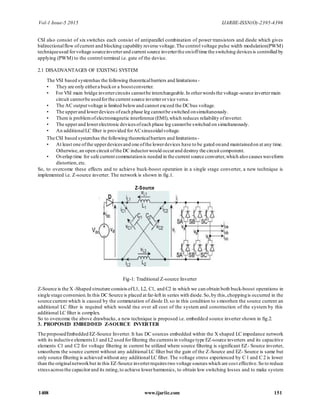
So, to overcome these effects and to achieve buck-boost operation in a single stage converter, a new technique is
implemented i.e. Z-source inverter. The network is shown in fig.1.
Z-Source
Fig-1: Traditional Z-source Inverter
Z-Source is the X -Shaped structure consistsofL1, L2, C1, and C2 in which we can obtain both buck-boost operations in
single stage conversion.In this DC Source is placed at far-left in series with diode.So,by this,choppingis occurred in the
source current which is caused by the commutation of diode D, so in this condition to s moothen the source current an
additional LC filter is required which would rise over all cost of the system and construction of the system by this
additional LC filter is complex.
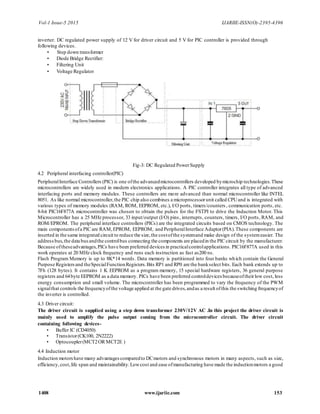
So to overcome the above drawbacks, a new technique is proposed i.e. embedded source inverter shown in fig.2.
3. PROPOSED EMBEDDED Z-SOURCE INVERTER
The proposedEmbedded EZ-Source Inverter. It has DC sources embedded within the X shaped LC impedance network
with its inductive elementsL1 and L2 used forfiltering the currents in voltage type EZ-source inverters and its capacitive
elements C1 and C2 for voltage filtering in current be utilized where source filtering is significant EZ- Source inverter,
smoothens the source current without any additional LC filter but the gain of the Z-Source and EZ- Source is same but
only source filtering is achieved without any additional LC filter. The voltage stress experienced by C 1 and C 2 is lower
than the originalnetworkbut in this EZ-Source inverterrequires two voltage sources which are cost effective.So to reduce
stressacrossthe capacitorand its rating,to achieve lowerharmonics, to obtain low switching losses and to make system
Vol-1 Issue-5 2015 IJARIIE-ISSN(O)-2395-4396
1408 www.ijariie.com 152
compact in size, a newtechnique is implemented i.e.partially parallel EZ- Source inverter With reduced switches. In this
paper, induction motor is taken as a load.
Fig -2: Proposed EmbeddedZ-source Inverter4.
BLOCK DIAGRAM OF HARDWARE DESIGN
The blockdiagramof single phase E-Z-source inverterusingpic controllerforspeed control of induction motor is shown
in fig.3. It contains following main section EZ-source inverter, pic controller, driver section, triggering circuit, speed
control circuit.
Fig-3: Block Diagramof Hardware Implementation.
The EZ-source inverter is utilized to realize inversion and boost function. A two port impedance network looks like
symmetrical lattice network most commonly used in filter and attenuator circuit. The microcontroller has been
programmed to the PWM signalofthe inverterand converts it to ac powerto feed the motorundercontrol.Fig.3shows the
hardware circuit implementation for this work
4. HARDWARE IMPLEMENTATION
4.1 DC Regulated Power Supply
The regulated power supply required to operation of driver circuit and PIC controller for the generation of gate
signal required for operation of semiconductor switching devices which are integrated in Embedded Z-source
Enhedbcd Z-Source
AC Rectifier EZ-Source Load
supply circuit inverter
network
I
Driver Unit 12v
4— Supply
t
Pic microcontroller 4— 5v
Vol-1 Issue-5 2015 IJARIIE-ISSN(O)-2395-4396
1408 www.ijariie.com 153
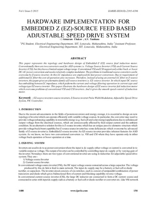
inverter. DC regulated power supply of 12 V for driver circuit and 5 V for PIC controller is provided through
following devices.
• Step down transformer
• Diode Bridge Rectifier:
• Filtering Unit
• Voltage Regulator
Fig-3: DC Regulated PowerSupply
4.2 Peripheral interfacing controller(PIC)
PeripheralInterface Controllers (PIC) is one ofthe advancedmicrocontrollers developed bymicrochip technologies.These
microcontrollers are widely used in modern electronics applications. A PIC controller integrates all type of advanced
interfacing ports and memory modules. These controllers are more advanced than normal microcontroller like INTEL
8051. As like normal microcontroller,the PIC chip also combines a microprocessorunit called CPUand is integrated with
various types of memory modules (RAM, ROM, EEPROM, etc.), I/O ports, timers/counters , communication ports, etc.
8-bit PIC16F877A microcontroller was chosen to obtain the pulses for the FSTPI to drive the Induction Motor. This
Microcontroller has a 25 MHz processor, 33 input/output (I/O) pins, interrupts, counters, timers, I/O ports, RAM, and
ROM/EPROM. The peripheral interface controllers (PICs) are the integrated circuits based on CMOS technology. The
main componentsofa PIC are RAM,EPROM, EEPROM, and PeripheralInterface Adaptor(PIA).These components are
inserted in the same integrated circuit to reduce the size,the costofthe systemand make design of the systemeasier. The
addressbus,the data busandthe controlbus connecting the components are placedin the PIC circuit by the manufacturer.
Because oftheseadvantages,PICs have been preferred devices in practicalcontrolapplications. PIC16F877A used in this
work operates at 20 MHz clock frequency and runs each instruction as fast as200 ns.
Flash Program Memory is up to 8K*14 words. Data memory is partitioned into four banks which contain the General
Purpose Registersand theSpecialFunctionRegisters.Bits RP1 and RP0 are the bankselect bits. Each bank extends up to
7Fh (128 bytes). It contains 1 K EEPROM as a program memory, 15 special hardware registers, 36 general purpose
registers and 64byte EEPROM as a data memory. PICs have been preferred controldevices becauseoftheirlow cost, less
energy consumption and small volume. The microcontroller has been programmed to vary the frequency of the PWM
signalthat controls the frequencyofthe voltage applied at the gate drives,andas a result ofthis the switching frequencyof
the inverter is controlled.
4.3 Driver circuit:
The driver circuit is supplied using a step down transformer 230V/12V AC .In this project the driver circuit is
mainly used to amplify the pulse output coming from the microcontroller circuit. The driver circuit
containing following devices-
• Buffer IC (CD4050)
• Transistor(CK100, 2N2222)
• Optocoupler(MCT2OR MCT2E )
4.4 Induction motor
Induction motorshave many advantagescomparedto DCmotors and synchronous motors in many aspects, such as size,
efficiency,cost,life span and maintainability.Lowcost and ease ofmanufacturing have made the inductionmotors a good
Vol-1 Issue-5 2015 IJARIIE-ISSN(O)-2395-4396
1408 www.ijariie.com 154
choice for electric and hybrid vehicles. In our project prototype motor is used. It is 3phae induction of 0.25 HP rating.
5. CONCLUSION
This paperpresentsa hardware designofnewtopologyforASDsystembasedon the EZ-source inverter. This design can
be implementing in very low cost.The EZ-source inverteremploys a unique LC impedance networkcouple to the inverter
main circuit and thus it providing unique features that are
1. Can produce anydesired outputac voltage,evengreaterthan theline voltage,
2.Provides ride-throughduringvoltage sags without anyadditionalcircuits and energy storage,minimizes the motor
ratings to delivera required power,and
3. reduces in-rush andharmonic current.
ACKNOWLEDGEMENT
This work is undergoingat SIT Lonavala,Pune University.The authorwould like to thank SIT College for their technical
support
REFERENCES
[1] Fang Zhengpeng “Z-source inverter,” IEEE Transactions on industry applications, vol. 39, No.2, March/April 2003
[2] K Ravi Chandrudu, P SangameswaraRaju, G V P Anjaneyulu “Case study of Embedded EZ-source inverter and
comparison with Z-source inverter," (IJAEST) International Journal of Advanced Engineering Sciences and
Technologies Vol. no. 6, Issue No. 2, 224 - 229
[3] Amol R. Sutar,SatywanR.Jagtap andJakirhusen Tamboli “Performance Analysis of Z-source inverter fed induction
motor drive,” International Journal of scientific & Engineering Research, Volume 3,Issue 5,May- 2012.
[4] Poh Chiang Loh, Feng Gao and Frede Blaabjerg “Embedded EZ-Source Inverters,” IEEE Transactions on industry
applications, vol. 46, No.1, January/February 2010.
[5] N. Gurusakthi and R. sivaprasad “Performance Enhancement of Ez-source Inverter Using Induction Motor,
“International Journal of scientific and Engineering Research, Volume 4, Issue 4, April-2013.ISSN 2229-5518
[6] G. Pandian and S. Rama Reddy “Embedded Controlled Z Source Inverter Fed Induction Motor Drive, “Journal of
Applied Sciences Research, 4(7): 826-832, 2008, INSI net Publication.
[7] K. shrinivasan and Dr. S.S. Dash “Performance Analysis of a Reduced Switch Z-Source Inverter fed IM Drives,
“International Journal of Computer and Electrical Engineering, Vol. 2, No. 4, August, 20101793 -8163.
[8] K Ravi Chandrudu, P Sangameswara Raju, G V P Anjaneyulu “EZ - source fed induction Motor drive: an
experimental Investigation” KRavi Chandruduet al./ International Journal of Engineering Science and Technology
(IJEST).
[9] M.S.Aspalli,Swapna Kumari Karanam, “Embedded ControlofZ Source InverterFed Induction Motor” Proceedings
of IRF International conference, 13th April-2014, Chennai, India, ISBN: 978-93-84209-05-6.
More Related Content

PDF
IRJET-PV Based Single Phase ZSI using Shoot through Technique
PPTX
Power Quality improvement in ZETA Converters for Brush-less DC Motors (BLDC)
PPT
SEMINAR TOPIC- 3 PHASE SELETOR AND PREVENTER FOR INDUSTRIAL APPS. 2007.ppt
DOCX
THE FABRICATION OF REGULATED DC POWER SUPPLY
PPTX
Self Switching Power Supply
PDF
Design and Construction of Automatic Three Phase Power System Selector
PPT
Dc Principal
PDF
Guidelines for power plants (smps)
IRJET-PV Based Single Phase ZSI using Shoot through Technique
Power Quality improvement in ZETA Converters for Brush-less DC Motors (BLDC)
SEMINAR TOPIC- 3 PHASE SELETOR AND PREVENTER FOR INDUSTRIAL APPS. 2007.ppt
THE FABRICATION OF REGULATED DC POWER SUPPLY
Self Switching Power Supply
Design and Construction of Automatic Three Phase Power System Selector
Dc Principal
Guidelines for power plants (smps)

What's hot (20)

PPTX
Power supply
PPTX
Digital phase selector
PPTX
AUTOMATIC ACTIVE PHASE SELECTOR FOR SINGLE ...
PDF
Project body(powersupply+timer+filter7thsem)
DOC
Automatic Phase Changer
PDF
Power factor corrected zeta converter based improved power quality switched m...
PPT
Digital phase changer ppt
PDF
POWER ELECTRONIC DEVICES
PPTX
Operation of brushless dc motor drive with zeta
PPTX
Ieee transfer schemes for M-T-M distribution systems
PPTX
Auto selection of any aviliable phase
PPTX
Auto power supply control from 4 different sources using pic microcontroller
DOC
Chapter 6 power electronic-devices
PDF
Report on minor project
DOCX
Power Supply Unit
PDF
IEEE substation design
PPT
Comparision of power electronic devices
PPTX
powergrid presentation
PDF
46584589 substation-design-data
PDF
5 FINAL PROJECT REPORT
Power supply
Digital phase selector
AUTOMATIC ACTIVE PHASE SELECTOR FOR SINGLE ...
Project body(powersupply+timer+filter7thsem)
Automatic Phase Changer
Power factor corrected zeta converter based improved power quality switched m...
Digital phase changer ppt
POWER ELECTRONIC DEVICES
Operation of brushless dc motor drive with zeta
Ieee transfer schemes for M-T-M distribution systems
Auto selection of any aviliable phase
Auto power supply control from 4 different sources using pic microcontroller
Chapter 6 power electronic-devices
Report on minor project
Power Supply Unit
IEEE substation design
Comparision of power electronic devices
powergrid presentation
46584589 substation-design-data
5 FINAL PROJECT REPORT
Ad

Similar to Hardware implementation for_embedded_z__ez__source_feed_based_adjustable_sp (20)

PPTX
Analysis, design and modeling of dc dc converter
PDF
Simulation of Z-Source Inverter for Induction Motor Drive
PPTX
BOOST DERIVED HYBRID CONVERTER
PDF
Closed Loop Controlled Solar Cell Powered Embedded EZ-Source Inverter fed Ind...
PDF
Simulation of Z-Source Inverter Fed Three Phase Induction Motor Drive
PDF
Analysis of the Performance of the Drive of the Z source Induction Motor Powe...
PDF
N01041106112
PDF
Iaetsd modeling of magnetically
PDF
SIMULATION STUDY OF QZSI Z-SOURCE INVERTER FOR RESISTIVE AND INDUCTIVE LOAD
PDF
IRJET- High Efficiency Bridge-Less Battery Charger for Light Electric Veh...
PDF
ZVS Circuit based – Cockcroft Walton High Voltage DC Generator
PDF
IRJET- Review of DC-DC Converters in Photovoltaic Systems for MPPT Systems
PDF
Quasi-z-source inverter for photovoltaic power generation systems
PDF
J0372049056
PDF
Control Scheme for Solar PV System under Asymmetrical Fault Condition
PPTX
Pre Final Year project/ mini project for Electronics and communication engine...
PDF
Research Inventy : International Journal of Engineering and Science
PDF
An Improved the High Voltage Boost Inversion Ability of Switched Inductor Qua...
PDF
IRJET- Mollification Parameter Control by Dynamic Voltage Restorer (DVR)
PDF
A fuzzy logic controlled dc dc converter for an
Analysis, design and modeling of dc dc converter
Simulation of Z-Source Inverter for Induction Motor Drive
BOOST DERIVED HYBRID CONVERTER
Closed Loop Controlled Solar Cell Powered Embedded EZ-Source Inverter fed Ind...
Simulation of Z-Source Inverter Fed Three Phase Induction Motor Drive
Analysis of the Performance of the Drive of the Z source Induction Motor Powe...
N01041106112
Iaetsd modeling of magnetically
SIMULATION STUDY OF QZSI Z-SOURCE INVERTER FOR RESISTIVE AND INDUCTIVE LOAD
IRJET- High Efficiency Bridge-Less Battery Charger for Light Electric Veh...
ZVS Circuit based – Cockcroft Walton High Voltage DC Generator
IRJET- Review of DC-DC Converters in Photovoltaic Systems for MPPT Systems
Quasi-z-source inverter for photovoltaic power generation systems
J0372049056
Control Scheme for Solar PV System under Asymmetrical Fault Condition
Pre Final Year project/ mini project for Electronics and communication engine...
Research Inventy : International Journal of Engineering and Science
An Improved the High Voltage Boost Inversion Ability of Switched Inductor Qua...
IRJET- Mollification Parameter Control by Dynamic Voltage Restorer (DVR)
A fuzzy logic controlled dc dc converter for an
Ad

Recently uploaded (20)

PDF
composite construction of structures.pdf
PPTX
FINAL REVIEW FOR COPD DIANOSIS FOR PULMONARY DISEASE.pptx
PPTX
Infosys Presentation by1.Riyan Bagwan 2.Samadhan Naiknavare 3.Gaurav Shinde 4...
PDF
Mitigating Risks through Effective Management for Enhancing Organizational Pe...
PPTX
CARTOGRAPHY AND GEOINFORMATION VISUALIZATION chapter1 NPTE (2).pptx
PPTX
additive manufacturing of ss316l using mig welding
PPT
Mechanical Engineering MATERIALS Selection
PPT
Introduction, IoT Design Methodology, Case Study on IoT System for Weather Mo...
PPT
Project quality management in manufacturing
PPTX
Safety Seminar civil to be ensured for safe working.
PPTX
Foundation to blockchain - A guide to Blockchain Tech
PPTX
UNIT-1 - COAL BASED THERMAL POWER PLANTS
PDF
Evaluating the Democratization of the Turkish Armed Forces from a Normative P...
PPTX
CYBER-CRIMES AND SECURITY A guide to understanding
PDF
BMEC211 - INTRODUCTION TO MECHATRONICS-1.pdf
PDF
Enhancing Cyber Defense Against Zero-Day Attacks using Ensemble Neural Networks
PDF
SM_6th-Sem__Cse_Internet-of-Things.pdf IOT
PDF
July 2025 - Top 10 Read Articles in International Journal of Software Enginee...
PDF
Embodied AI: Ushering in the Next Era of Intelligent Systems
PPTX
UNIT 4 Total Quality Management .pptx
composite construction of structures.pdf
FINAL REVIEW FOR COPD DIANOSIS FOR PULMONARY DISEASE.pptx
Infosys Presentation by1.Riyan Bagwan 2.Samadhan Naiknavare 3.Gaurav Shinde 4...
Mitigating Risks through Effective Management for Enhancing Organizational Pe...
CARTOGRAPHY AND GEOINFORMATION VISUALIZATION chapter1 NPTE (2).pptx
additive manufacturing of ss316l using mig welding
Mechanical Engineering MATERIALS Selection
Introduction, IoT Design Methodology, Case Study on IoT System for Weather Mo...
Project quality management in manufacturing
Safety Seminar civil to be ensured for safe working.
Foundation to blockchain - A guide to Blockchain Tech
UNIT-1 - COAL BASED THERMAL POWER PLANTS
Evaluating the Democratization of the Turkish Armed Forces from a Normative P...
CYBER-CRIMES AND SECURITY A guide to understanding
BMEC211 - INTRODUCTION TO MECHATRONICS-1.pdf
Enhancing Cyber Defense Against Zero-Day Attacks using Ensemble Neural Networks
SM_6th-Sem__Cse_Internet-of-Things.pdf IOT
July 2025 - Top 10 Read Articles in International Journal of Software Enginee...
Embodied AI: Ushering in the Next Era of Intelligent Systems
UNIT 4 Total Quality Management .pptx

Hardware implementation for_embedded_z__ez__source_feed_based_adjustable_sp

  • 1. Vol-1 Issue-5 2015 IJARIIE-ISSN(O)-2395-4396 1408 www.ijariie.com 150 HARDWARE IMPLEMENTATION FOR EMBEDDED Z (EZ)-SOURCE FEED BASED ADJUSTABLE SPEED DRIVE SYSTEM1 2 Atmaram Chakor , A.V. Tamhane 1 PG Student, Electrical Engineering Department, SIT, Lonavala, Maharashtra, India 2 Assistant Professor, Electrical Engineering Department, SIT, Lonavala, Maharashtra, India ABSTRACT This paper represents the topology and hardware design of Embedded-Z (EZ) source feed induction motor. Conventionally there are twoconverters used for ASD systems i.e. Voltage Source Inverter (VSI) and Current Source Inverter(CSI),but theyhavea limitedoutput voltagerange.Conventional VSIandCSIsupportonlyeither buck or boost DC-AC powerconversion and needa relatively complex modulator.The problems in traditional source converterscanbe overcome by Zsource inverter. In this LC impedance are employed for fast power conversion. Due to requirement of additionalLC filterthe cost of operation also increases. Therefore, instead of using an external LC filter in Z-source inverters,thispaper givesan alternative family ofZ-source inverters i.e.EZ-source inverter. In which input DC source hasembedding betweenLC impedance,which performthe current and voltage filtering operation in current type and voltagetype EZsource inverter. This paper illustrate the hardware design of EZ source inverter fed induction motor which overcome problemsof conventional VSI and CSI inverters. And it gives the smooth speed control of induction motor. Keyword: - EZ-source inverters-source inverters,Z-Source inverter Pulse WidthModulation,Adjustable Speed Drive System, PIC Controller. 1. INTRODUCTION Due to the recent advancements in the fields of powerconversion and energy storage, it is essential to design an new topologyofinverterwhich can operate efficiently with variable voltage sources. In particular, the converter may need to provide voltageenhancing capability in renewable energy (e.g.fuelcell and solarenergy)applications due to unbalanced output voltage from the electrical sources, which are unnecessarily affected by their output current and the ambient condition.So an alternative solution forthis is Z-source inverter,which has an unique passive elements structure which provide voltagebuck-boost capability but Z-source source inverterhas some deficiencies which overcome by advanced family of Z-source inverteri.e.Embedded Z-source inverter.An EZ-source inverter provides inherent features for ASD system. As we know, we have two conventional converters i.e. VSI and CSI where they have operate only in either voltage buck operation or boost operation at a time. 2. EXISTING SYSTEM Inverters are usedto dc to ac powerconversionwhere the input is dc supply either voltage or current is converted in to variable output ac voltage.The output of invertercan be controlled by controlling input dc supply or by varying gain of the inverter. Nowadays there are two types of conventional inverter are using in industries for adjustable speed drive system. They are:- 1) Voltage source Inverter 2) Current source Inverter. In conventionalvoltage source inverter(VSI), the DC input voltage source connected across a large capacitor.The voltage produced by this dc link is feed to main network. The input dc supply may be a battery or fuel cell or diode rectifier, or capacitors.The invertercircuit consists of sixswitches; each is consist of antiparallel combination of power transistors and diode which gives bidirectional flow of current and blocking capability reverse voltage. In conventional current-source inverter (CSI), the large DC inductor are connected to form a DC current source and connected in series with inputdc supply such as a battery or fuel-cell or diode rectifier or converter etc. Like VSI network
  • 2. Vol-1 Issue-5 2015 IJARIIE-ISSN(O)-2395-4396 1408 www.ijariie.com 151 CSI also consist of six switches each consist of antiparallel combination of power transistors and diode which gives bidirectionalflow ofcurrent and blocking capability reverse voltage.The control voltage pulse width modulation(PWM) techniqueused forvoltage sourceinverterand current source inverterthe on/offtime the switching devices is controlled by applying (PWM) to the control terminal i.e. gate of the device. 2.1 DISADVANTAGES OF EXISTNG SYSTEM The VSI based systemhas the following theoreticalbarriers and limitations- • They are only eithera buckor a boostconverter. • For VSI main bridge invertercircuits cannotbe interchangeable.In otherwords the voltage-source invertermain circuit cannotbe usedforthe current source inverterorvice versa. • The AC outputvoltage is limited belowand cannot exceed the DCbus voltage. • The upperand lowerdevices ofeach phase leg cannotbe switched onsimultaneously. • There is problemofelectromagnetic interference (EMI),which reduces reliability ofinverter. • The upperand lowerelectronic devices ofeach phase leg cannotbe switched on simultaneously. • An additionalLC filter is provided forACsinusoidalvoltage. The CSI based systemhas the following theoreticalbarriers and limitations- • At least one ofthe upperdevicesand one ofthe lowerdevices have to be gated onand maintainedon at any time. Otherwise,an open circuit ofthe DC inductorwould occurand destroy the circuit component. • Overlap time for safe current commutationis needed in the current source converter,which also causes waveform distortion,etc. So, to overcome these effects and to achieve buck-boost operation in a single stage converter, a new technique is implemented i.e. Z-source inverter. The network is shown in fig.1. Z-Source Fig-1: Traditional Z-source Inverter Z-Source is the X -Shaped structure consistsofL1, L2, C1, and C2 in which we can obtain both buck-boost operations in single stage conversion.In this DC Source is placed at far-left in series with diode.So,by this,choppingis occurred in the source current which is caused by the commutation of diode D, so in this condition to s moothen the source current an additional LC filter is required which would rise over all cost of the system and construction of the system by this additional LC filter is complex. So to overcome the above drawbacks, a new technique is proposed i.e. embedded source inverter shown in fig.2. 3. PROPOSED EMBEDDED Z-SOURCE INVERTER The proposedEmbedded EZ-Source Inverter. It has DC sources embedded within the X shaped LC impedance network with its inductive elementsL1 and L2 used forfiltering the currents in voltage type EZ-source inverters and its capacitive elements C1 and C2 for voltage filtering in current be utilized where source filtering is significant EZ- Source inverter, smoothens the source current without any additional LC filter but the gain of the Z-Source and EZ- Source is same but only source filtering is achieved without any additional LC filter. The voltage stress experienced by C 1 and C 2 is lower than the originalnetworkbut in this EZ-Source inverterrequires two voltage sources which are cost effective.So to reduce stressacrossthe capacitorand its rating,to achieve lowerharmonics, to obtain low switching losses and to make system
  • 3. Vol-1 Issue-5 2015 IJARIIE-ISSN(O)-2395-4396 1408 www.ijariie.com 152 compact in size, a newtechnique is implemented i.e.partially parallel EZ- Source inverter With reduced switches. In this paper, induction motor is taken as a load. Fig -2: Proposed EmbeddedZ-source Inverter4. BLOCK DIAGRAM OF HARDWARE DESIGN The blockdiagramof single phase E-Z-source inverterusingpic controllerforspeed control of induction motor is shown in fig.3. It contains following main section EZ-source inverter, pic controller, driver section, triggering circuit, speed control circuit. Fig-3: Block Diagramof Hardware Implementation. The EZ-source inverter is utilized to realize inversion and boost function. A two port impedance network looks like symmetrical lattice network most commonly used in filter and attenuator circuit. The microcontroller has been programmed to the PWM signalofthe inverterand converts it to ac powerto feed the motorundercontrol.Fig.3shows the hardware circuit implementation for this work 4. HARDWARE IMPLEMENTATION 4.1 DC Regulated Power Supply The regulated power supply required to operation of driver circuit and PIC controller for the generation of gate signal required for operation of semiconductor switching devices which are integrated in Embedded Z-source Enhedbcd Z-Source AC Rectifier EZ-Source Load supply circuit inverter network I Driver Unit 12v 4— Supply t Pic microcontroller 4— 5v
  • 4. Vol-1 Issue-5 2015 IJARIIE-ISSN(O)-2395-4396 1408 www.ijariie.com 153 inverter. DC regulated power supply of 12 V for driver circuit and 5 V for PIC controller is provided through following devices. • Step down transformer • Diode Bridge Rectifier: • Filtering Unit • Voltage Regulator Fig-3: DC Regulated PowerSupply 4.2 Peripheral interfacing controller(PIC) PeripheralInterface Controllers (PIC) is one ofthe advancedmicrocontrollers developed bymicrochip technologies.These microcontrollers are widely used in modern electronics applications. A PIC controller integrates all type of advanced interfacing ports and memory modules. These controllers are more advanced than normal microcontroller like INTEL 8051. As like normal microcontroller,the PIC chip also combines a microprocessorunit called CPUand is integrated with various types of memory modules (RAM, ROM, EEPROM, etc.), I/O ports, timers/counters , communication ports, etc. 8-bit PIC16F877A microcontroller was chosen to obtain the pulses for the FSTPI to drive the Induction Motor. This Microcontroller has a 25 MHz processor, 33 input/output (I/O) pins, interrupts, counters, timers, I/O ports, RAM, and ROM/EPROM. The peripheral interface controllers (PICs) are the integrated circuits based on CMOS technology. The main componentsofa PIC are RAM,EPROM, EEPROM, and PeripheralInterface Adaptor(PIA).These components are inserted in the same integrated circuit to reduce the size,the costofthe systemand make design of the systemeasier. The addressbus,the data busandthe controlbus connecting the components are placedin the PIC circuit by the manufacturer. Because oftheseadvantages,PICs have been preferred devices in practicalcontrolapplications. PIC16F877A used in this work operates at 20 MHz clock frequency and runs each instruction as fast as200 ns. Flash Program Memory is up to 8K*14 words. Data memory is partitioned into four banks which contain the General Purpose Registersand theSpecialFunctionRegisters.Bits RP1 and RP0 are the bankselect bits. Each bank extends up to 7Fh (128 bytes). It contains 1 K EEPROM as a program memory, 15 special hardware registers, 36 general purpose registers and 64byte EEPROM as a data memory. PICs have been preferred controldevices becauseoftheirlow cost, less energy consumption and small volume. The microcontroller has been programmed to vary the frequency of the PWM signalthat controls the frequencyofthe voltage applied at the gate drives,andas a result ofthis the switching frequencyof the inverter is controlled. 4.3 Driver circuit: The driver circuit is supplied using a step down transformer 230V/12V AC .In this project the driver circuit is mainly used to amplify the pulse output coming from the microcontroller circuit. The driver circuit containing following devices- • Buffer IC (CD4050) • Transistor(CK100, 2N2222) • Optocoupler(MCT2OR MCT2E ) 4.4 Induction motor Induction motorshave many advantagescomparedto DCmotors and synchronous motors in many aspects, such as size, efficiency,cost,life span and maintainability.Lowcost and ease ofmanufacturing have made the inductionmotors a good
  • 5. Vol-1 Issue-5 2015 IJARIIE-ISSN(O)-2395-4396 1408 www.ijariie.com 154 choice for electric and hybrid vehicles. In our project prototype motor is used. It is 3phae induction of 0.25 HP rating. 5. CONCLUSION This paperpresentsa hardware designofnewtopologyforASDsystembasedon the EZ-source inverter. This design can be implementing in very low cost.The EZ-source inverteremploys a unique LC impedance networkcouple to the inverter main circuit and thus it providing unique features that are 1. Can produce anydesired outputac voltage,evengreaterthan theline voltage, 2.Provides ride-throughduringvoltage sags without anyadditionalcircuits and energy storage,minimizes the motor ratings to delivera required power,and 3. reduces in-rush andharmonic current. ACKNOWLEDGEMENT This work is undergoingat SIT Lonavala,Pune University.The authorwould like to thank SIT College for their technical support REFERENCES [1] Fang Zhengpeng “Z-source inverter,” IEEE Transactions on industry applications, vol. 39, No.2, March/April 2003 [2] K Ravi Chandrudu, P SangameswaraRaju, G V P Anjaneyulu “Case study of Embedded EZ-source inverter and comparison with Z-source inverter," (IJAEST) International Journal of Advanced Engineering Sciences and Technologies Vol. no. 6, Issue No. 2, 224 - 229 [3] Amol R. Sutar,SatywanR.Jagtap andJakirhusen Tamboli “Performance Analysis of Z-source inverter fed induction motor drive,” International Journal of scientific & Engineering Research, Volume 3,Issue 5,May- 2012. [4] Poh Chiang Loh, Feng Gao and Frede Blaabjerg “Embedded EZ-Source Inverters,” IEEE Transactions on industry applications, vol. 46, No.1, January/February 2010. [5] N. Gurusakthi and R. sivaprasad “Performance Enhancement of Ez-source Inverter Using Induction Motor, “International Journal of scientific and Engineering Research, Volume 4, Issue 4, April-2013.ISSN 2229-5518 [6] G. Pandian and S. Rama Reddy “Embedded Controlled Z Source Inverter Fed Induction Motor Drive, “Journal of Applied Sciences Research, 4(7): 826-832, 2008, INSI net Publication. [7] K. shrinivasan and Dr. S.S. Dash “Performance Analysis of a Reduced Switch Z-Source Inverter fed IM Drives, “International Journal of Computer and Electrical Engineering, Vol. 2, No. 4, August, 20101793 -8163. [8] K Ravi Chandrudu, P Sangameswara Raju, G V P Anjaneyulu “EZ - source fed induction Motor drive: an experimental Investigation” KRavi Chandruduet al./ International Journal of Engineering Science and Technology (IJEST). [9] M.S.Aspalli,Swapna Kumari Karanam, “Embedded ControlofZ Source InverterFed Induction Motor” Proceedings of IRF International conference, 13th April-2014, Chennai, India, ISBN: 978-93-84209-05-6.