


![DOCUMENTATION AND DRAWINGS
The use of standard drawing formats makes it easier for
architects to layout drawings for discussion in the design
office or on the building site, and also facilitates posting and
filing. The trimmed, original drawing or print must therefore
conform to the formats of the ISO A series. ----? @ - ®
The box for written details should be the following
distance from the edge of the drawing:
for formats AO-A3 10 mm
for formats A4-A6 5 mm
For small drawings, a filing margin of up to 25 mm can be
used, with the result that the usable area of the finished
format will be smaller.
As an exception, narrow formats can be arrived at by
stringing together a row of identical or adjacent formats out
of the format range.
From normal roll widths, the following sizes can be used
to give formats in the A series:
for drawing paper, tracing paper 1500, 1560 mm
(derived from this 250, 1250,660,900 mm)
for print paper 650, 900, 1200 mm
If all the drawing formats up to AO are to be cut from a
paper web, a roll width of at least 900 mm will be necessary.
Drawings which are to be stored in A4 box files should
be folded as follows: ----? @
(1) The writing box must always be uppermost, in the
correct place and clearly visible.
(2) On starting to fold, the width of 210 mm (fold 1)
must always be maintained, and it is useful to use a
210 x 297 mm template.
(3) Fold 2 is a triangular fold started 297 mm up from the
bottom left-hand corner, so that on the completely
folded drawing only the left bottom field, indicated
with a cross, will be punched or clamped.
(4) The drawing is next folded back parallel to side 'a'
using a 185 x 298 mm template. Any remaining area
is concertina-folded so as to even out the sheet size
and this leaves the writing box on the top surface. If
it is not possible to have even folds throughout, the
final fold should simply halve the area left (e.g. A 1
fold 5, AO fold 7). Any longer standard formats can be
folded in a similar way.
(5) The resulting strip should be forded from side 'b' to
give a final size of 210 x 297 mm.
To reinforce holes and filing edges, a piece of A5 size
cardboard (148 x 210 mm) can be glued to the back of the
punched part of the drawing.
~
. . . . / ~
VNW
cut-out ISO A2, A 1, AO
cut-out ISO A3
cut-out ISO A4
~ - l:':7:.. . . . .. .
~
I
_ _ ::::::J
divisions
for
12
594
® ISO size A5
o Field divisions (grid squares)
ISO A2
lil
I
I
I
--~
ISO A3
D
r
I
I~
LJ
a
-+20 l-
I writing box
® ISO size A4
® Dimensions and scheme for folding
IH-+--+--
I
I
I '"'-+r--.r-,.---.-~-.---"---;--r---i
L=:
.......--'-_~t-L--.~_----L-...lL_."..-L-...L-_..&....-.lII~----L..._--~
o ISO size A2; A1; AO
uncut drawing sheet,
depending on requirement,
is 2-3cm wider than
final trimmed original
drawing and print
box for written
r--9
details and
parts list
I a
I
sheet sizes in acc. ISO AO ISO A1 ISO A2 ISO A3 ISO A4 ISO A5
with ISO A series
uncut blank 880" 1230 625,,880 450,625 330,450 240 x 330 165 x 240
paper (mm)
format trimmed, 8410..1189 594,841 420,594 297,420 210,,297 148 x 210
finished sheet (rnrn]
G) Standard drawing
o Sheet sizes
5](https://image.slidesharecdn.com/neufert-arch-datacompress-231212110729-3be4aee5/85/neufert-arch-data_compress-pdfdataaaaaaa-8-320.jpg)

![Designers use drawings and
illustrations to communicate
information in a factual,
unambiguous and geometric
form that can be understood
anywhere in the world. With
good drawing skills it is simpler
for designers to explain their
proposals and also give clients a
convincing picture of how the
finished project will look. Unlike
painting, construction drawing
is a means to an end and this
differentiates diagrams/working
drawings and illustrations from
artistic works.
Sketch pads with graph
paper having a.5cm squares are
ideal for freehand sketches to
scale ----) CD. For more accurate
sketches, millimetre graph
paper should be used. This has
thick rules for centimetre
divisions, thinner rules for half
centimetres and fine rules for
the millimetre divisions.
Different paper is used for
drawing and sketching accord-
ing to standard modular
coordinated construction and
engineering grids ----) (2). Use
tracing paper for sketching with
a soft lead pencil.
Suitable sheet sizes for
drawings can be cut straight
from a roll, single pages being
torn off using a T-square or cut
on the underside of the T-square
----) @. Construction drawings are
done in hard pencil or ink on
clear, tear-resistant tracing paper,
bordered with protected edges ----)
® and stored in drawers or hung
in vertical plan chests.
Fix the paper on a simple
drawing board (designed for
standard formats), made of
limewood or poplar, using
drawing pins with conical points
----) @. First turn over 2cm width
of the drawing paper edge,
which can later be used as the
filing edge (see p. 4), for this lifts
the T-square a little during
drawing and prevents the
drawing being smudged by the
T-square itself. (For the same
reason, draw from top to
bottom.) The drawing can be
fixed with drafting tape rather
than tacks ----) @ if a plastic
underlay backing is used.
The T-square has tradit-
ionally been the basic tool of the
designer, with special T-squares
used to draw lines at varying
angles. They are provided with
octameter and centimetre
divisions ----) (f). In general,
however, the T-square has been
replaced by parallel motion
rulers mounted on the drawing
board ----) @. Other drawing aids
include different measuring
scales ----)@, 45° set squares with
millimetre and degree divisions,
drawing aids for curves ----) @,
and French curves ----) @.
a
.....;jIJ
b
CONSTRUCTION DRAWINGS
)!iSt <:1...
guided by little finger
on the edge
® Set squares
® Specialist drawing board
~
.~
o Cutting paper to size
@ Drawing movements
@ Correct way of holding a
pencil
'$i5wrong shape
(drawing pin)
folding over prevents
tearing
Sketching: construction
engineering grid
set of
kales
'" II
N
~
~
~ 0
'"
,..,.
...l
0
'"
N
A.
T
250
-~
250
"'::~ 1125 750
~
J.. '1 1111
0 "
'"
N
IITnl "II I IJI
cone shape:
correct
® Drawing equipment
CD
® Drawing table
@ French curves
@ Aid for hatching
G) Paper for sketching
ISO A4
CD Taping edges
(]) T-square
@ Drawing aids
@ Drawing aids
7](https://image.slidesharecdn.com/neufert-arch-datacompress-231212110729-3be4aee5/85/neufert-arch-data_compress-pdfdataaaaaaa-10-320.jpg)

![CONSTRUCTION DRAWINGS
line types (weight) primary application scale of drawings
1:1 1:20 1:100
1:5 1:25 1:200
1:10 1:50
line thickness (mm)
solid line boundaries of buildings in section 1.0 0.7 0.5
(heavy)
solid line visible edges of components; boundaries of narrow 0.5 0.35 0.35
(medium) or smaller areas of building parts in section
solid line dimension guide lines; dimension lines; grid lines 0.25 0.25 0.25
(fine)
indication lines to notes; working lines 0.35 0.25") 0.25
dashed line') hidden edges of building parts 0.5 0.35 0.35
(medium)
----
chain dot line indication of section planes 1.0 0.7 0.5
(heavy)
._._.
chain dot line axes 0.35 0.35 0.35
(medium)
.__.__.
dotted line') parts lying behind the observer 0.35 0.35 0.35
(fine)
'I
dashed line - - - - - - dashes longer than the distance between them
dotted line dots (or dashes) shorter than the distance between them
"I
0.35 mm if reduction from 1:50 to 1:100 is necessary
In some European countries the
measurement unit used in connection
with the scale must be given in the
written notes box (e.g. 1:50 ern). In the
UK, dimensions are given only either in
metres or millimetres so no indication of
units is required. Where metres are used
it is preferable to specify the dimension
to three decimal places (e.g. 3.450) to
avoid all ambiguity.
1 2 3 4
unit dimensions
under 1 m over 1 m
e.g. e.g.
1 m 0.05 0.24 0.88 3.76
2 cm 5 24 88.5 376
3 m,cm 5 24 885 3.76
4 mm 50 240 885 3760
® Units of measurement
- - - - - tiles
-- mortar
- screed
damp-proof membrane
insulation
structural floor
® Indication lines to notes
note: for plotter drawings using electronic data processing equipment and drawings destined for microfilm, other combinations of
line widths may be necessary
4
3
a
Oa
o Designation for dimensioning
i-----------dimension figure
I 1-----dimension line
: r -~ extension line
I .>; dimension arrow
-3.76~
==u
01
Ob
Ob1 Ob2
02
oc
3E
----- ---- ---- - -Ilt-- -
---r-
I b24,
I
I
I
I
I
I
I
I c2
I
I
I
I
I
I
I
I
1
I
I
I
I I
I
-~ I I
---- - I I
I
I 1
I
0208 I I I
01
C(
<
w
~
''It
~
C
U
CD
-c
0
-c
o
CI
0
CD
0
axis
field
'1J (J)
] .~
® Axis-field grid
000
426
188.S - - - # - # - - - - - - -
24
Dimensions given by coordinates
(drawn at 1:50cm, m; units = cm and m)
Dimensions given around the drawing
(drawn at 1:100cm; units = cm)
I
~
I I
~O>
~ ~~
~l .=--1~
24r188.s*~i-- 426 - 24
236.S-"1 -437.S-
-674-
885
___.t:::======1...._.J::::======L__I-~ 625
CD
G) Types and thicknesses of lines to be used in construction drawings
1#=~-J615t625l1135J615l1~1865
266 138.S 437 -S_1--.;38;...;:.-:.S'---_____+_
236 674
CD Dimensions of piers and apertures
(drawn at 1:50 cm; units = cm)
9](https://image.slidesharecdn.com/neufert-arch-datacompress-231212110729-3be4aee5/85/neufert-arch-data_compress-pdfdataaaaaaa-12-320.jpg)


![GL= goods lift
PL = passenger lift
FL = food lift
HL = hydraulic lift
ventilation and
extraction shaft
cookers/hobs fuelled
by gas
cookers/hobs fuelled
by oil
cookers/hobs fuelled
by solid fuels
top cupboard
ironing board
cupboard/
base unit
central heating
radiator
® oil fired boiler
@ gas fired boiler
@
@ laundry chute
@ refuse chute
@ boiler (stainless)
® cooker
@ dishwasher
@ electric cooker/hob
@
@
@
@
@ freezer
@ refrigerator
Other symbols
-"-
.x:n?~ .
~
J..·....·..··..·L
Jitn
.
:
:
:
:
:..::: ::
.:..r r :/.::.
fi
:?·:::~::::::::
:.~::
:::t t.:::
JiXIt
.
~
. : :.
"C2J .
.. ..
:: ~ :.
.::.} .::I::
urinal bowl
35/30
shower
80 x 80, 90 x 90, 75 x 90
bidet
38 x 60
stepped sinks
corner shower
90 x 90
twin sinks,
single drainer
60 x 150
sit-up bath
70 x 105,70 x 125
row of urinals
single sink
and drainer
60 x 100
built-in wash-basin
45 x 30
kitchen waste sink
wardrobe
60 x 120
twin wash-basins
60 x 120,60 x 140
bath
75 x 170,85 x 185
wash-basin
50 x 60, 60 x 70
two wash-basins
toilet
38 x 70
double bed
150 x 195
child's bed
70 x 140-170
twin bed
2(95 x 195, 100 x 200)
bed 95 x 195
bedside table
50 x 70, 60 x 70
CONSTRUCTION DRAWINGS: SYMBOLS
@
@)
@
o ]1
D@
Kitchen
Bedroom
Bathroom
~
l~ool
DO
o
rn @
o @
[] ®
coat rack
hooks,
15-20cm apart
laundry basket 40/60
baby's changing unit 80/90
sewing table 50/50-70
sewing machine 50/90
grand pianos
baby 155 x 114
drawing-room 200 x 150
concert 275 x 160
chair, stool (3 45 x 50
extending table
round table
(3 90 = 6 people
table
85 x 85 x 78 = 4 people
130 x 80 x 78 = 6 people
'19' linen cupboard
~ 50 x 100-180
f2i'o desk
'e:!J 70 x 1.30 x 78
80 x 1.50 x 78
@
@)
@ flower stands
@ chest 40/1.00-1.50
@ cupboard 60/1.20
@
@
® television
@
® upright piano 60/1.40-1.60
® arm chair 70 x 85
()) chaise-longue 95 x 195
® sofa 80/1.75
®
® shaped table 70-100
®
CD
I
, ,
EJ
I I I I I I I
EUilWrlliJ
Cloakroom
D
o
o
CJ)
DO
IDI
[;?1
11--11
living room
12](https://image.slidesharecdn.com/neufert-arch-datacompress-231212110729-3be4aee5/85/neufert-arch-data_compress-pdfdataaaaaaa-15-320.jpg)


![r---700 --1
1--------1125-------1
@
~
(
0
~
(")
~
N
1250
@ Dimensions: armchair
r--625 -----i
r------ 875 ---------1
r-----900 - 1000---1
Dimensions: small easy
chair
r---875~
In accordance with normal measurements and energy
consumption
@
•
r---- 875--1
t------625 -----1
o
MAN: DIMENSIONS AND SPACE
REQUIREMENTS
Body measurements
~875------1
Dimensions: sitting and
dining room chair
-=====r
r---750~
CD
r--625 --i ~ 300-i
® ®
I 1375-------4
CD
~---r
I ' )
I
I
I
I ~
(])
~875------i
@ Dimensions: work table
I - - - 710-----1
: I
I I
i -----!]
'0
IN
:~
I
I
I
I
I
I
1
8
~
T
~660---1
I .
I
I
@ Working while standing @ Kneeling @ Sitting @ Squatting
f---------2000-----~
~----1625--------1
~----1500-----l
1---1250-----1
16](https://image.slidesharecdn.com/neufert-arch-datacompress-231212110729-3be4aee5/85/neufert-arch-data_compress-pdfdataaaaaaa-19-320.jpg)


![Interpretation
THE EYE: PERCEPTION
The activity of the eye is divided into seeing and observing.
Seeing first of all serves our physical safety but observing
takes over where seeing finishes; it leads to enjoyment of
the 'pictures' registered through seeing. One can
differentiate between a still and a scanned picture by the
way that the eye stays on an object or scans along it. The
still picture is displayed in a segment of the area of a circle,
whose diameter is the same as the distance of the eye from
the object. Inside this field of view the objects appear to the
eye 'at a glance' ~ @. The ideal still picture is displayed in
balance. Balance is the first characteristic of architectural
beauty. (Physiologists are working on a theory of the sixth
sense - the sense of balance or static sense - that underpins
the sense of beauty we feel with regard to symmetrical,
harmonious things and proportions (~ pp. 27-30) or when
we are faced with elements that are in balance.)
Outside this framework, the eye receives its impressions
by scanning the picture. The scanning eye works forward
along the obstacles of resistance which it meets as it directs
itself away from us in width or depth. Obstacles of the same
or recurring distances are detected by the eye as a 'beat' or
a 'rhythm', which has the same appeal as the sounds
received by the ear from music. 'Architecture is Frozen
Music. This effect occurs even when regarding a still or
scanned picture of an enclosed area ~ CD and @.
A room whose top demarcation (the ceiling) we
recognise in the still picture gives a feeling of security, but
on the other hand in long rooms it gives a feeling of
depression. With a high ceiling, which the eye can only
recognise at first by scanning, the room appears free and
sublime, provided that the distance between the walls, and
hence the general proportions, are in harmony. Designers
must be careful with this because the eye is susceptible to
optical illusions. It estimates the extent of width more
exactly than depths or heights, the latter always appearing
larger. Thus a tower seems much higher when seen from
above rather than from below ~ p. 24 @ and @. Vertical
edges have the effect of overhanging at the top and
horizontal ones of curving up in the middle ~ p. 24 CD - @,
(j]). When taking these things into account, the designer
should not resort to the other extreme (Baroque) and, for
example, reinforce the effect of perspective by inclined
windows and cornices (St Peter's in Rome) or even by
cornices and vaulting painted in perspective and the like.
The decisive factor for the measurement of size is the size
of the field of view ~ @ and, if applicable, the field of vision
~ @ and, for the exact differentiation of details, the size of
the field of reading ~ @ and @. The distance of the latter
determines the size of the details to be differentiated.
The Greeks complied exactly with this rule. The size of
the smallest moulding under the cornice of the individual
temples of varying height is so dimensioned that, at an
angular distance of 27° ~ (j), it complies with the reading
field of 0°1'. From this also results the reading distances for
books (which varies with the size of the letters) and the
seating plans for auditoriums etc.
a 'L.;.b
beadln~~
the main
cornice
As in the previous examples,
the size of structural parts
which are differentiable
can be calculated using the
viewing distance and
trigonometry
~ 3.0 ---i
The field of view of the
normal fixed eye takes in a
perimeter of 10
(approx. the
area of a thumbnail of an
outstretched hand)
---"
In higher rooms, the eyes
must scan upwards (l.e, scan
picture)
individual
features can
present larger
surfaces to the
eye with a
little shaping
(j)
CD
15.0
~" ',.~"
" __- l"t
-----6~-- -- 2tO
.1.75
~ height necessary for
same effect at a
distance of 8.50 m
viewing distance E = object size -:- tan 0°1'
object size = E x tan 0°1' = 0.000291E
human 8.50m
To be readable at a distance
of, say, 700m the width w
of the letters must be:
? 700 x 0.000291 = 0.204;
height h is usually 5w:
5xO.204 = 1.020m
The eye can resolve detail within a perimeter of only 0 01'
(the
field of reading), thus limiting the distances at which objects
and shapes can be distinguished accurately ~ @
~ 3.0 ~
The human field of vision
(head still, moving the eyes
only) is 540
horizontally,
270
upwards and 100
downwards
The perception of a low room
is gained 'at a glance' (i.e.
still picture)
printed text T
17-34cm L!)
~""' N
~._ VI .0
f
70 ~ 1 '.:
jewellery
<,30cm hHntUre .- ~
~an4.0 m 'tU re 3.3011'
r te ~urn
y---orna
E
~ w?E,tanOol'=E-:-3450
E < 3450 x w
r·,::-__~T
~1
.-- lh ~
finer details
~ 2h ----1
general appearance
I 3h I
total overview of surrounding area
w = 1 part
)-- ~"1
h = 5 parts
only applicable with : .'
good illumination;
otherwise 1'/2 to
twice the size
CD
®
CD
® Street widths play an
important role in the level
of detail which is perceived
from ground level
® Parts of buildings meant
to be seen but sited above
projections must be placed
sufficiently high up (see a)
25](https://image.slidesharecdn.com/neufert-arch-datacompress-231212110729-3be4aee5/85/neufert-arch-data_compress-pdfdataaaaaaa-28-320.jpg)

![DIMENSIONAL RELATIONSHIPS
Basis
There have been agreements on the dimensioning of
buildings since early times. Essential specific data
originated in the time of Pythagoras. He started from the
basis that the numerical proportions found in acoustics
must also be optically harmonious. From this, Pythagoras
developed his right-angled triangle --1 CD. It contains all the
harmonious interval proportions, but excludes both the
disharrnonious intervals (i.e. the second and seventh).
Space measurements are supposed to have been
derived from these numerical proportions. Pythagoras or
diophantine equations resulted in groups of nurnerals v- (2)
- @ that should be used for the width, height and length of
rooms. These groups can be calculated using the formula
a2 + b2 = c2.
a2 + b2 = c2
a = m(y2 - x2)
b=m-2-x-y
c = m(y2 + x2)
In this x and yare all whole numbers, x is smaller than y,
and m is the magnification or reduction factor.
The geometric shapes named by Plato and Vitruvius are
also of critical importance (i.e. circle, triangle --1 @ and square
~ ® from which polygonal traverses can be constructed).
The respective bisection then results in further polygonal
traverses. Other polygonal traverses (e.g. heptaqon v- @,
nonagon ~ @) can only be formed by approximation or by
superimposition. So we can construct a fifteen-sided figure
~ @ by superimposing the equilateral triangle on the
pentagon.
The pentagon or pentagram has a natural relationship
with the golden section, just like the decagon which is
derived from it @, @ and ~ p. 30. However, in earlier times
its particular dimensional relationships found hardly any
application. Polygonal traverses are necessary for the
design and construction of so-called 'round' structures. The
determination of the most important measurements (radius
r, chord c, and height of a triangle h) are shown in --1 @ and
@.
Pythagoras's triangle
~
12
® Square
8) Example
(3)
Equilateral triangle, hexagon
minor third 5/6
fourth 3/4
Some numerical relationships
from Pythagoras's equations
Pythagoras's rectangle includes
all interval proportions and
excludes the disharmonious
second and seventh
®
a a b c ~ m x y
36°87' 3 4 5 53°13' 1 1 2
22°62' 5 12 13 67°38' 1 2 3
16°26' 7 24 25 73°74' 1 3 4
28°07' 8 15 17 61°93' 0.5 3 5
12°68' 9 40 41 7]032' 1 4 5
18°92' 12 35 37 71°08' 0.5 5 7
43°60' 20 21 29 46°40' 0.5 3 7
31°89' 28 45 53 58°11' 0.5 5 9
h = %. cotanp
B
%=r.sin~
h = r • cos p
arc of the circle at A with AS results
in point 0 on AC = c-:
arc of the circle at C with CM results
in point E on arc of SO = a;
segment DE approximately corresponds
with 1/9 of the circle's circumference 0
@ Approximated nonagon
straight SC bisects AM at 0;
SO is approx. 1/7 of the circumference
of the circle
® Approximated heptagon
I---m---i
.....-....---M-------I
c
B
A
Fifteen angle Be =~ - ! =1-
5 3 15
~ M I m---4
~M-+-m-1
~M~m----i
r-m-t--M--tm+-M-i
I
®
I
I
I
I
I
I
I I I
~M-+--m--i
r-M--f-m"'"
~M--+--m~
f-m+-M~M-+-m-1
I I I I
I I I IT
I I
I I
: : m
, ,t
1
chord = r
A
bisection of the radius , S;
arc at S with AS C
A - C . side of a pentagon
o Pentagon
@ Pentagon and golden section @ Decagon and the golden
section
Measurement calculation in
polygonal traverse ~ p. 28
@ ~ @formula
27](https://image.slidesharecdn.com/neufert-arch-datacompress-231212110729-3be4aee5/85/neufert-arch-data_compress-pdfdataaaaaaa-30-320.jpg)
![DIMENSIONAL RELATIONSHIPS
Basis
~n = 1 + ~--=-l ~ Q]).
1+G
A right-angled isosceles (i.e. having two
equal sides) triangle with a base-to-height
ratio of 1:2 is the triangle of quadrature.
An isosceles triangle with a base and
sides that can be contained by a square was
successfully used by Knauth, the master of
cathedral construction, for the determination
of the dimensional relationships for the
Strasbourg Cathedral.
Drach's rr/4 triangle ~ CD is somewhat
more pointed than the previous one described, as its height
is determined by the point of a slewed square. It, too, was
successfully used for details and components.
Apart from these figures, the dimensional proportions of
the octagon can be detected on a whole range of old
structures. The so-called diagonal triangle serves as a basis
here. The triangle's height is the diagonal of the square built
on half the base ~ (2)- @.
The sides of the rectangle depicted in @ have a ratio of
1:~2. In accordance with this, all halvings or doublings of
the rectangle have the same ratio of 1: ~2. The 'step ladders'
within an octagon make available the geometric ranges in
(2)- @. The steps of square roots from 1-7 are shown in @.
The connection between square roots of whole numbers is
shown in (f).
The process of factoring makes possible the application
of square roots for building in non-rectangular components.
By building up approximated values for square figures,
Mengeringhausen developed the MERD space frames. The
principle is the so-called 'snail' ~ @ - @. The inaccuracies
of the right angle are compensated for by the screw
connections of the rods at the joints. A subtly differentiated
approximated calculation of square roots of whole numbers
vn for non-rectangular components is available from the
use of continued fractions (~ p. 30) in the formula
expressed as G =
7 = 2.646
t-- ----.,.;..... 6 = 2.450
1 (square)
2 = 1.414
~1
~---- 5 = 2.236
t--_-- 4 = 2.000
(double square)
3 = 1.732
1---1 ~
® Step ladder of square roots
10
o Squares developed from the
octagon ~ (2)- @
450
'At
'At If.
'At v'2
If. '12
If. v'2
'12
rr/4 triangle
(according to A. V. Drach)
r------- 1 - - - - . . I
® 1: 2 rectangle
CD
(}) Connection between square
roots
20
28
40
28
® The 'Snail'
1 I )11 1
0.5 2ktJ' 1.5
0.6 51 7 1.4
0.58333 ... 12 17 1.41667...
0.58621 ... 29~4t 1.41379 ...
0.5857143 ... 701 99 1.4142857 ...
0.5857989 ... 169 !239 1.4142011 ...
0.5857865 ... v'2 1.4142135...
® Non-rectangular co-ordination -
MERO space frames: building
on 2 and 3 ..
~ pp. 90-91
@ Continued fraction 2
28](https://image.slidesharecdn.com/neufert-arch-datacompress-231212110729-3be4aee5/85/neufert-arch-data_compress-pdfdataaaaaaa-31-320.jpg)


![Floor-to-floor height:
30M = 300:19 = 15.8
select 16 steps
step rise:
h = 3
1°6°
= 18.75 cm
Overall length:
16.26 = 416cm
select 420 = 42 M
Tread going:
b=419=26.2cm
16
(assuming joint dimension of 1em)
MODULAR SYSTEM
International agreements on the planning and execution of
building work and for the design and manufacture of
building components and semi-finished products are
incorporated into national standards. The modular system
is a means of coordinating the dimensions applicable to
building work.
The term 'coordination' is the key, indicating that the
modular layout involves an arrangement of dimensions and
the spatial coordination of structural components. Therefore,
the standards deal with geometrical and dimensional
requirements. The modular system develops a method of
design and construction which uses a coordinate system as a
means of planning and executing building projects. A
coordinate system is always related to specific objects.
Geometric considerations
By means of the system of coordinates, buildings and
components are arranged and their exact positions and
sizes specified. The nominal dimensions of components as
well as the dimensions of joints and interconnections can
thereby be derived. ~ CD - ®, @
A coordinate system consists of planes at right angles to
each other, spaced according to the coordinate
measurements. Depending on the system, the planes can
be different in size and in all three dimensions.
As a rule, components are arranged in one dimension
between parallel coordinate planes so that they fill up the
coordinate dimension, including the allowance allocated to
the joints and also taking the tolerances into account. Hence
a component can be specified in one dimension in terms of
its size and position. This is referred to as boundary
reference. ~-1 (f) -~ @
In other cases, it can be advantageous not to arrange a
component between two planes, but rather to make the
central axis coincide with one plane of the coordinate system.
The component is initially specified in one dimension with
reference to its axis, but in terms of position only. -C> (]) • C!~
A coordinate system can be divided into sub-systems for
different component groups, e.g. load-bearing structure,
component demarcating space, etc ...~ ®
It has been established that individual components need
not be modularised, e.g. individual steps on stairways,
windows, doors, etc. ~ @
For non-modular components which run along or across
the whole building, a so-called 'non-modular' zone can be
introduced, which divides the coordinate system into two-
sub systems. The assumption is that the dimension of the
component in the non-modular zone is already known at
the time of setting out the coordinate system, since the non-
modular zone can only have completely specified
dimensions. ~ ®
Further possible arrangements of non-modular
components are the so-called centre position and edge
position within modular zones.-1 ® - @
•
Relationship between axis
reference and modular
material zone
Superimposed partial
coordinate system
@
®
",
o Coordinate plane
r~ •
Boundary reference Axis reference
(j) Boundary reference,
axis reference
~@
o Coordinate space (bounded
by 6 planes)
Laterally connected, non-
modular components in an
edge position
Laterally connected, non-
modular components in a
central position
Coordinate point (point of
intersection of 3 planes)
Alignment of coordinate
(intersection line of 2 planes)
Components in the
coordinate system
l:l:lltl:]
l=lj:t:l=l
204M
r
~~72M- -48M- -----84M~
~
112 12Y18 30 30 18 12Y 30 18?1212
Y ? i 6t--61
I T 121
1
r ~itchen ...ztore 33M T
v
staff WCF WCM
r-, L ~ :12T 15
3i
M
V cafeteria/ T
3JM
96M 114M
till/
snacks JP
)
I
kiosk r-,
12 l 0
" 12
V ""
'" ~ 12 12M
I
1
, r
I
;:)=tz;;I~==r::
® Non-modular zone
®
CD
CD Coordinate system
@ Preliminary design - motorway service area @ Reinforced concrete staircase unit
34](https://image.slidesharecdn.com/neufert-arch-datacompress-231212110729-3be4aee5/85/neufert-arch-data_compress-pdfdataaaaaaa-37-320.jpg)


![Twentieth century: covered
walkway leads from car to
door (wired plate glass),
which slides open when an
electric eye is activated
Twentieth century houses
have no enclosure (in the
US, particularly) and stand
unobtrusively among trees in
large communal parks
®
Around 1700, doors had
clear glass panes with
decorative glazing bars
(also, a bell-pull)
In the 1800s, detached
houses were built in open
surroundings with low
fences
THE DESIGN OF HOUSES
The Expression of the Period and its
Conventions
(])
By 1500: heavy, studded
doors with knocker, and
windows with bars and
bull's eye panes
By 1700 walls and gates were
only symbolic, giving
glimpses of the garden
®
CD
~~~
Around AD 1500, houses and
towns were protected by high
walls and heavy gates
" »>>,>,>>»»>>> ».>~
AD 1000: log cabins had low
doors, high thresholds; no
windows; lit through an
opening in the roof
ROOM CONNECTIONS
ENTRANCES
ACCESS
Twentieth century rooms
are flexible: sliding walls
and plate glass windows;
venetian blinds/shutters as
protection from the sun
@
By 1900, sliding doors were
fitted between rooms,
linoleum flooring, sliding
windows, and draw curtains
In the 1700s, wide double
doors led into suites of
rooms with parquet flooring
AD 1500: low, heavy doors,
sparse daylighting, and
floors of short, wide boards
HOUSES
®
open
terrace
Architect:
Mies van der Rohe
scullery
servery
We,and
washroom
street side
dining room
garden side
toilet
bedroom
ground
floor
valley
..-=---=-.. side
hill
.a;;;;;;:;:;::ij. side
@ The timber house (AD 1500)
was influenced by the
environment, method of
construction and the way of
life; e.g. Walser house
The stone house (AD 1500):
massive walls, to combat
enemies/cold, required the
same area as the rooms
themselves
The house of the 2000s will have slender steel supports and
slim non-load-bearing curtain walling, the composition of which
affords full protection against the weather, and maximum noise
and heat insulation. Open plan, with dividing screens between
living area, dining room and hall (no doors)
In the time between the beginning of the 16th century (the
period of witch-hunts, superstition, leaded lights and fort-
like houses, a form which is still occasionally in demand)
and the present day, astonishing advances have been made
in science, technology and industry. As a result the outlook
of society has changed radically. In the intervening
centuries it is clearly evident from buildings and their
details, as well as other aspects of life, that people have
become freer and more self-aware, and their buildings
lighter and brighter. The house today is no longer perceived
as a fortress offering protection against enemies, robbers or
'demons' but rather as a complementary framework for our
way of life - open to nature and yet in every respect
protected against its inclemency.
People generally see and feel things differently.
Designers must therefore use their creativity as far as
possible to translate our shared experience into reality and
express it through the materials at their disposal. The
attitude of the client is of the greatest significance in this
issue. In some ways, many clients and architects are still
living in the 15th century while few of each have arrived in
the new millennium. If the 'centuries' meet in the right way,
then a happy marriage between client and architect is
assured.
39](https://image.slidesharecdn.com/neufert-arch-datacompress-231212110729-3be4aee5/85/neufert-arch-data_compress-pdfdataaaaaaa-42-320.jpg)


![blackor galvanrsec f.rushto Bf
qual11
Information on this page was provided by the Stanley Partnership, Cheltenham.
Interim
Certificate
--
G
I/W" ~I"r'h' re-rtrfv that the amou nt d ue toth. l'untradHrfn,rn tht
~:lJlpk"':l'r l~ (1Il wurd''''f
11 l'h,· tont ractor ha-. ~I't'n notu-c t ha t th,· rah'llfVXrdlttr~t'ablt'(lll th,
,..upph l!f);:uud~ <111,1 s,-'r'o'l''S to wtucb tilt" Contruct rvlates I:;' "o
An interim certificate according to RIBA
(3)
CONSTRUCTION MANAGEMENT
-IBO: STEFLPIPLWURI SCRFWFIlr-;O HAr-;GED)U[:-"l'S
thereaftershallbebuuweldecor weldedflanged jonusoa.,. Weldedioimsmoll
however.beusedonanlllleo!bla.:ksleelpIjJeworke..:er'loltlallel"pl!Jeltne
anc.llanes andconnecnons toecuiprnem Allweldediom'; shal:havebeveliec
mitredends
Above:)Ommdiameter p.llanlled sle~l pipework<nai.hale all buttweidecand
weldedflangedtonus
-IB.03BLACK ASOGALAISED STITL PIPESUPTU I)OMMOlA~lLTER
ShallbemIICIleeleie<:rn.:alreIlSLlIKe.:onIH1GOulilseamweidedlubeo!tubeo!
,~lD5S_101 ~8) andIll' heav. weight
.lB.().lBLACK STEELPIPL5OVERIlOMM DIA~lET[R
Blacksteelpipesabove150mm snallbecarbonsteelhOI timshedseamlesslube
11IJ·.""'.U<I"UJ_'c~.BS'bOi ISO:bO.l::N.l.ll :bO.lbandBSSllf,
Iq8Q Thenururnum wallth.ckness shall'eolslheioliowtng table
SOl:llnal Diameter
100
350,-Ili,)
-150 olnd ol~lle
Extract from a specification of piped services
Architect's
Instruction
Fdbrl.catedweldablesteel,8S4360Grdde43,treated
~~~andtopcoatasclauseGlO/640atttroOrks
Wlm1i-x)sts, as drawings 953 SK 118-119;
Hd.:tenHKTtlesat225centres; i nc Lud i nq
p Lat e s , ariq Le brec ket s , and all bolt.s
e
UI LD: IlG
E WAL:.S
E MJrr."'2
eorrn:i<lC
BUILD:IlG
E WAL:.S
I ' ,
I
Contractor
address
Wor ks
situated at
C0I-.llnys;proflleasdrawlnq735jWD/6J
4':JCxgUi type A.; horizontal; splayed
t;.Jp;grooves-2
225x55;tyt:JleB;hut"l.zontal;
top;grooves-l
horlzontal.;splayed [ l SI~lw.1 EnJU'~' [ ] PIan"u,. Supon_"
__ Q.'_Omua""'SOb(~,,,~wn n-"..
~('o".ol~l_ __LI
[
II
[I""
CD Extract from a bill of quantities
Summary
31/07/97
Valuation No 2
Phase 2
City works
Alfred Street
Gloucester
o An architect's instruction according to RIBA form
Stanley Partnership
RECORD
Date
Job HOUSE AT BLOCKLEY 82i19
Telephone Number 01242242943
Meeting/Telephone/Drawing is sc e
1 As valuation summary
2 Materials on site:
[ 32,933.32
[ 3,750.00
I have spoken to the engineer and the CtLCUN ~UlA~ blocks rnov tle used
provrdeo they ore the 3Sk version
Use dense blocks for Internal partitions tor sound re s.st.mce and butt JOint With
Inner skin
At each butt JOint use expanded metal folded to lorm on l With JO() mm leq,
Incorporate every other course
All corners thus formed to have double plaster slop beaejs m movemenl
48
Valuation total f 36,683.32
Less retention 5.00% [1,834.17
[ 34,849.16
Less previously certified [ 8,816.92
[ 26,032.24
VAT @ 17.50% [4,555.64
Valuation for payment [ 30,587.88
Page 1
® Example of architect's valuation ® Architect's record of a communication](https://image.slidesharecdn.com/neufert-arch-datacompress-231212110729-3be4aee5/85/neufert-arch-data_compress-pdfdataaaaaaa-51-320.jpg)


![DAMP-PROOFING AND TANKING
Cellars are used less these days as storage rooms and more
as places for leisure or as additional rooms for
accommodation and domestic purposes. So, people want
greater comfort and a better internal climate in the cellar. A
prerequisite for this is proofing against dampness from
outside. For buildings without cellars, the external and
internal walls have to be protected from rising damp by the
provision of horizontal damp-proof courses ----. @ - @. On
external walls, the damp-proofing is 150-300 mm above
ground level ~ @ - @. For buildings with brick cellar walls,
a minimum of 2 horizontal damp-proof courses should be
provided in the external walls ----. CV-@. The upper layer may
be omitted on internal walls. Bituminous damp-proof
membranes, asphalt, or specifically designed high-grade
plastic sheet should be used for the vertical tanking in walls.
Depending on the type of back filling used in the working
area and the type of tanking used, protective layers should
be provided for the wall surfaces ~ @ - @. Rubble, gravel
chippings or loose stones should not be deposited directly
against the tanking membrane.
water occurs as proofing required against type of proofing
rising damp capillary effect on vertical protective layers against ground
building elements dampness (damp proofing)
precipitation, seepage of water not under proofing against seepage
running water pressure on sloping surfaces (tanking)
of building elements
ground water hydrostatic pressure pressure retaining proofing
(tanking)
finished floor
level
/
Damp-proofing of building
with no cellar and with non-
habitable room use; floor at
ground level
Good protection required on
hill side of building; hillside
water conducted away by
drainage ---1 @ - @
ground
level
CD
air space
supporting
floor
finished floor
level
/
/
finished floor
level
Damp-proofing of building
with no cellar and with non-
habitable room use; hardcore
at the level of the damp-
proof course
Cellar level protected
horizontally and vertically
against rising damp
·CV-@
CD
CD
corrugated fibre
protective layer
fibre cement
sheet over
tanking
material
finished
cellar floor
level
finished
cellar floor
level
raft foundation
@ Protective layer of fibre
cement boards
@ Damp-proofing and tanking
of building with cellar;
masonry walls on a raft
foundation
ventilated f,a<;:ade ~
gravel bed
for splash
protection ""
finished
cellar floor
level
finished ground
floor level
- waterproof mat
seepage layer
Damp-proofing and tanking
of building with cellar;
walls of concrete
@ Waterproof mat
®
finished
cellar floor
level
tanking
protective layer
of concrete grid
units
o
M
/I
Protective wall of concrete
grid units
Damp-proofing of building
with cellar; masonry walls
on strip foundations
Damp-proofing of building
with no cellar; low lying
floor at ground level
ground
level
@
finished
cellar floor
level
Damp-proofing of building
with cellar with non-
habitable room use (masonry
walls on strip foundation)
Damp-proofing of building
with no cellar; floor with
ventilated air gap between
floor and ground level
(])
water seepage
through pores
@ Drainage and tanking
®
59](https://image.slidesharecdn.com/neufert-arch-datacompress-231212110729-3be4aee5/85/neufert-arch-data_compress-pdfdataaaaaaa-62-320.jpg)
![30 40 50
15 20
- - - corrugated plastic drainpipe
5 6 7 8 9 10
flow rate Q (I/s) ~
- - concrete land drains
y /
// II' II
lJI
v...~
/
b%g !~#~
VL
/
Q'
/ ~I
/~7 °1
I
/ I /
I /, I !I
I I II I
I / / IJ I
/ I
!J I
I I / lh / /
/ II
I
!/
/' / I
I I / I /; / /
" #/ /;' ~ / 'II
"" s. I ~ II It --f---- ~
"'-.(~ ~ I 'I / /
,,~/ jJ V /
k' ~'/
V I
"rtj /
'-II r-~~I
V
"l~I
0.1
0.05
1
3.0
2.0
1.5
1.0
0.8
0.6
~
~ 0.4
0.3
drainpipe: nominal diameter 100mm, 0.5% fall
washout and inspection pipe: nominal diameter 300 rnrn
washout, inspection and collecting shaft: nominal diameter 1000 mm
Ground Water Drainage
DAMP-PROOFING AND TANKING
0.2
Ground water drainage involves the removal of water from
the building site area through drainage layers and
drainpipes to prevent the build-up of water pressure. This
process should prevent blocking by soil particles (fixed filter
drainage). A drainage facility consists of perforated drains,
inspection and cleaning devices, and drainage pipes for
water disposal. Drainage is the collective term for drain
pipes and drainage layers. If drainage at the wall is
necessary, reference should be made to the cases ,G) - ]1.
~~... CD is relevant if ground dampness only occurs in very
porous ground.-. (2)is relevant if the accumulation of water
can be avoided by means of a drain, so that water under
pressure does not occur..) Qj is relevant if water is present
under pressure, as a rule in the form of ground water, or
when removal of the water via a drain is not possible.
@ Measurement nomogram for drainage pipework
@ Specifications and depths of granular materials for drainage layers
position material thickness (Ill)
in front of walls sand/gravel '0.50
filter layer coarseness 0-4 rnrn '0.10
seepage layer coarseness 4-32 rnrn '0.20
gravel coarseness 4-32 mm and geotextile -0.20
on roof slabs gravel coarseness 4-32 mm and geotextile '0.50
under floor slabs filter layer coarseness 0.4 mm '0.10
seepage layer coarseness 4-32 mill
gravel coarseness 4-32 mm and geotextile
around land drains sand/gravel -0.15
seepage layer coarseness 4~32 mill and '010
filter layer coarseness 0-4 rnrn
gravel coarseness 4-32 mm and geotextile -0.10
finished
ground
floor level
ON 300
~ - 0 -
-6'. . ~~o_~'~lIiiIi~~~
OVlroo
ON 100
ON 100
Key to diagrammatic
representation
Drainage system for deep
building work
Non-pressurised water in
slightly porous ground
I *-
I~~
Is
rr7---r-J.....,....r-T'.......-7'~~.......,....,...A , ~
~~~---~]
representation component material
~ filter layer sand
geotextile
----- (filter fleece)
IlS
•
Q
c.«i1 drainage gravel
layer individual/
composite
~
elements
(drainage
units, boards)
~ (drainage mat)
-- protective, membrane,
~ separating render
-- d/proofing
_.. _.. - drainpipe
washout!
_.~. inspecnon
-~~-
pipe
washout!
inspection/
collecting
shaft
CD
finished
cellar floor
level
finished
ground
floor level
0 - - -
OVl300
ON 300
0--
~Ni
Dl4i888
Y7ZZzzz:z.ZZI:2.-:z::zz..Z:Z:Z:::;;"::Z:Z:2-.:z::z:z.zzz:z.::z:zz:;'[IZZ:z:;~
I I
I
#- I
~ ~I
I
~I
~~-
Example of an arrangement of drainpipes, inspection and
cleaning access in a ring drainage system
Soakaway for low drainage
requirement
l:0.3.l
Drainage system with ®
granular material around
the pipe (tile drain)
ON 300 ~~
0 - - -
o 0
o
o
o 0
(])
®
o
o .
. . 0 0 . G.·
o
o..~ .......
,....,..,r"'7'"7~".....,....~
O .
.'~'. ~:-Oo 0~.o.~0 ..~o•.~".o:~·
o Water under pressure in
ground containing ground
water
60](https://image.slidesharecdn.com/neufert-arch-datacompress-231212110729-3be4aee5/85/neufert-arch-data_compress-pdfdataaaaaaa-63-320.jpg)


![Masonry walling has to be braced with lateral walls and the
tops restrained by upper floors (cellular principle). Bracing
walls are plate-like components which stiffen the structure
against buckling ~ p. 63 @. They are rated as supporting
walls if they carry more than their own weight from one
storey. Non-supporting walls are plate-like components
which are stressed only by their own weight and do not
provide buckling support. Recesses and slots have to be cut
out or positioned in the masonry bonds. Horizontal and
slanting recesses are permitted, but with a slenderness
ratio of ~ 140 mm and thickness ~ 240 mm under special
requirements ~ p. 63 @. Ties should be provided for
connection between external walls and partition walls
acting as bracing walls that transmit horizontal loads.
Horizontal reinforcement is required in structures of more
than two complete storeys or which are more than 18[t]m
long, if the site conditions demand it, or where there are
walls with many or large openings (if the sum of the
opening widths is more than 600
/0 of the wall length, or
where the window width is over 2/3 of the storey height or
more than 400/0 of the wall length).
MASONRY
Bricks and Blocks
block block dimension number wall per me per m '
format format (em) of courses thickness of wall of masonry
per 1rn (em)
no. of mortar no. of mortar
height
blocks (litre) blocks (litre)
OF 24" 11.5 5.2 16 11.5 66 29 573 242
~
132 68 550 284
36.5 198 109 541 300
:n
~ NF 24,11.5,7.1 12 11.5 50 26 428 225
~~ 24 99 64 412 265
36.5 148 101 406 276
~-:
u~ 2 OF 24" 11.5" 11.3 8 11.5 33 19 286 163
~ 0 24 66 49 275 204
e E
36.5 99 80 271 220
.g ~
~~
3 OF 24" 17.5 -, 11.3 8 175 33 28 188 160
~ 24 45 42 185 175
2
Q. 4 OF 24,24 11.3 8 24 33 39 137 164
::J
8 OF 24 ' 24 ' 23.8 4 24 16 20 69 99
blocks blocks 49.5, 17.5 ,23.8 4 17.5 8 16 46 84
and and 49.5 " 24 " 23.8 4 24 8 22 33 86
hollow hollow 49.5 " 30 " 23.8 4 30 8 26 27 88
blocks blocks 37,24 ,23.8 4 24 12 26 50 110
37 ,30 " 23.8 4 30 12 32 42 105
245 " 36.5 ' 23.8 4 36.5 16 36 45 100
@ Setting out dimensions for masonry work
@ Building material requirements for masonry work
heading
lengthwise number
height dimension (rn). with block thickness (rnm:
dimension" (rn) of
number
00 OS OL courses 52 71 113 155 175 238
1 0.115 0.135 0.125 1 0.0625 0.0833 0.125 0.1666 01875 025
2 0.240 0.260 0.250 2 0.1250 0.1667 0.250 0.3334 0.3750 050
3 0.365 0.385 0.375 3 0.1875 0.2500 0375 0.5000 0.5625 0.75
4 0.490 0.510 0.500 4 0.2500 0.3333 0.500 0.6666 0.7500 100
5 0.615 0.635 0.625 5 0.3125 0.4167 0.625 0.8334 0.9375 125
6 0.740 0.760 0.750 6 0.3750 0.5000 0.750 1.0000 1.1250 1.50
7 0.865 0.885 0.875 7 0.4375 0.5833 0.875 1.1666 1.3125 175
8 0.990 1.010 1.000 8 0.5000 0.6667 1.000 1.3334 1.5000 2.00
9 1.115 1.135 1.125 9 0.5625 0.7500 1.125 1.5000 16875 2.25
10 1.240 1.260 1.250 10 0.6240 0.8333 1250 1.6666 1.8750 250
11 1.365 1.385 1.375 11 0.6875 0.9175 1.375 1.8334 20625 2.75
12 1.490 1.510 1.50 12 0.7500 1.0000 1.500 2.0000 2.2500 3.00
13 1.615 1.635 1.625 13 0.8125 10833 1.625 2.1666 24375 3.25
14 1.740 1.760 1.750 14 0.8750 1.1667 1.750 2.3334 2.6250 3.50
15 1.865 1.885 1.875 15 0.9375 1.2500 1.875 2.5000 2.8125 3.75
16 1.990 2.010 2.000 16 1.0000 1.3333 2000 2.6666 3.0000 400
17 2.115 2.135 2.125 17 1.0625 1.4167 2.125 2.8334 3.1875 4.25
18 2.240 2.260 2.250 18 1.1250 1.5000 2.250 3.0000 3.3750 450
19 2.365 2.385 2.375 19 1.1875 1.5833 2375 3.1666 3.5625 475
20 2.490 2510 2.500 20 1.2500 1.6667 2500 33334 3.7500 5.00
* 00 = outer dimension, as = opening size, OL = overlap
Special wall blocks with
insulation and mortar
filling channels
Poroton blocks with mortar
filling
Masonry in hollow blocks
with in situ reinforced
trough lintel
Reinforced masonry for
door or window lintel
®
®
o Detail at base
Building blocks with 5 cm
insulation layer and mortar
filled cavities
Masonry of light concrete
blocks (hollow blocks) with
reinforced pumice concrete
lintel
Crossover with reinforced
light concrete masonry
blocks
Double leaf masonry with
full fill cavity insulation
(}) Aerated concrete blocks
with cemented joints: 1 mm
®
®
CD
I~
L 11
5
L
4 J L 17
5
r 1 ;>10 (24)
insulation ~
layer ,~~
CD
64](https://image.slidesharecdn.com/neufert-arch-datacompress-231212110729-3be4aee5/85/neufert-arch-data_compress-pdfdataaaaaaa-67-320.jpg)


![(I) Fireplace open on one side
with safety area
FIREPLACES
Every open fire must be connected to its own separate flue
and should be immediately adjacent to the next • (jJ - ~4!.
Flue cross-sections must be matched to the size of the open
fire-) @. The effective height of the flue from the smoke
hood to the chimney mouth should be ~ 4.5 m. The angle of
a connecting flue to the main flue should be 45° ,,@ - QQ).
Open fires must not be sited in rooms with less than 12 m 2
floor area. Only wood with a low resin content, and beech,
oak, birch or fruit tree timber with few knots, should be used
for burning. In the case of the use of gas appliances,
reference should be made to the relevant regulations.
Air for combustion must come from outside and needs
to be able to enter even if the doors and windows are
airtight. Air admission openings can usefully be sited in the
base of the fire, or at the front, and ducts that introduce air
to a position close to the fireplace opening should be
provided --) o»
The fireplace opening must be separated from
combustible materials and built-in furniture by at least
800[t]mm to the front, above and to the sides. ®-c: Open
fires must be constructed from non-combustible materials
that satisfy local regulations and must be of stable
construction. The floor, walls and grate and the smoke hood
should be made from fire clay bricks/slabs, fire resistant
concrete or cast iron (although the grate and hood are often
metal). Any bricks or stones used must be of suitable type
for chimney construction. Smoke hoods can be made from
2 mm steel brass, or copper sheet.
50
Fireplace open on two
sides with safety area
Fireplaces open on one
side in separate rooms
CD
Fireplaces open on one/two
sides in separate rooms
o
@ Fireplace tools
@ Fireplace open on three sides
® Dimensions and sizes of open fires
type open on 1 side open on 2 Sides open on 3 Sides
1 2 3 4 5 6 7 8 9 10 11
room area small 16- 22- 30- 33- 25- 35- over 35- 45- over
(m 2) rooms 22 30 35 40 35 45 48 45 55 55
room volume small 40- 60- 90- 105- 90- 105- over 35 45 over
(m 3 ) rooms 60 90 105 120 105 150 150 150 150 200
size of fire 2750 3650 4550 5750 7100 5000 6900 9500 7200 9800 13500
opening (crn/)
dimension 60/ 70/ 80/ 90/ 100/
fire opening (em) 46 52 58 64 71
diameter (em) 20 22 25 30 30 25 30 35 25 30 35
of associated flue
all A 22.5 24 25.5 28 30 30 30 30 30 30 30
dimensions B 13.5 15 15 21 21 - - -
(em) C 52 58 64 71 78 50 58 65 50 58 65
0 72 84 94 105 115 77 108 77 90 114
E 50 60 65 76 93 77 90 108 77 90 114
F 19.5 19.5 22.5 26 26 27.5 30 32.5 27.5 30 32.5
G 42 47 51 55 59 64 71 82 64 71 82
H 88 97 104.5 120 129 80 88 95 80 88 95
I 6 6 6 7 7 6.4 64 64 6.4 6.4
weight 165 80 310 385 470 225 300 405 190 255 360
Protection of combustible
floor from the fireplace
opening/air admission
@ Fireplace open on two sides
:::::::::::::::::::::::::::::::::
=+'
Separation of fireplace
opening from combustible
materials
Heat radiation surfaces and
directions
®
® Fireplace open on one side
®
68](https://image.slidesharecdn.com/neufert-arch-datacompress-231212110729-3be4aee5/85/neufert-arch-data_compress-pdfdataaaaaaa-71-320.jpg)

![ground floor
2nd floor
opposite facing
duct openings
staggered by 1
brick height
(33.3cm)
1st floor
.....................
! ~M-
~ 50 cellar
~~:~:I
:=JQQQl::::
·····~~···+i::::
Example of system with
one main duct and two
auxiliary ducts
dividing -
floor
dividing -
floor
baffle - ~j
plate ~1
@
:•.•.............•.•.....•....•..., ,.,.".,.,.,.•.•.,',.•.•.....••..•.•...•..........
..............................•....
inspection doors
clear width 400 mm
baffle
plate
=t~ 15
~ 50
I:U bath/WC
~:~
Branching duct ventilation
system with one main and
one auxiliary duct
-::.::.:::.:::.;.;.:.;.; ;.;.;.:.:::,,::.;.;.;..:::..: .
dividing floor
cellar
ground floor
1st floor
2nd floor
cover with Meidinger disk
clear permissible no. of adjacent duct internal dimensions
cross-section connections with average
of the main effective total height main duct auxiliary duct
duct ern? up to 10m 10-15m over 15m (cm) (ern)
340 5 6 7 20'>< 17 9" 17
400 6 7 8 20" 20 12, 20
500 8 9 10 25" 20 12 ' 20
340 5 6 7 20" 17 2,9/17
400 6 7 8 20" 20 2 , 12/20
500 8 9 10 25" 20 2 ,,12· 20
340 5 6 7 2 'x 12/17 9 -, 17
400 6 7 8 2 x 20/20 12 , 20
500 8 9 10 2 " 25/20 12 ,20
VENTILATION DUCTING
® Table of dimensions for branching duct convection systems
Q1x15/10 [tJ=ghx15/10 OOO3x15/1O
[gggg]4X1S/10 !OOOOOSX1S/10 [OOOO!OCJ]6X1S/10
!ooooloool7X15/10 ~DODDLJL~J8x15/10
~ . . . thin walled - lengthwise; web
® Smgle duct ventilation thickness 5cm
air exit on two opposite sides; exit area
per side equal to the sum of all duct
cross-sections
f:~u;~
~I:·'I~~r~·!'r-
.:.: ::-,:
~' ..
Extract fan units should meet the ventilation requirements
of bathrooms and lavatories in residential and non-
residential buildings (such as schools, hotels and guest
houses) and extract air from one or several rooms into an
extract duct ~ CD - (2). Ventilation systems should be sized
for a minimum of 4 complete changes of air in the rooms
which need to be ventilated. A flow of 60 m3/h is adequate
for bathrooms with a toilet and a flow of 30 m3/h is adequate
for one toilet. Every internally sited room to be ventilated
must have a non-closable ventilation opening. The size of
the area through which air flows must be 100 mrn-' for every
m 3 of room volume. Gaps around the door may be taken as
equivalent to 250 rnrn-'. In bathrooms, the temperature must
not fall below 22°C, due to the flow of air.
The velocity of flow in the living area should be 2:: 0.2 rn/s.
The exhausted air must be led outside. Each individual
ventilation system must have its own main duct « @- @.
Central ventilation systems have common main ducting
for a number of living areas ~ @ - @.
The effective functioning of branching duct convection
ventilation systems depends essentially on the available
cross-section area of duct available per connection -~ @.
The cross-section of the ventilation shaft for single-duct
systems without mechanical extract ~ (J) in bathrooms and
WCs without open windows (up to 8 storeys) should be
1500mm2 per room.
ground
floor
• 1st floor
4- air inlet
duct connector 80 mm
dia.' 30mm long
secondary duct
connector 80 mm
dia.» 30mm long
air inlet -.
air inlet
Supply and extract
convection ventilation
system
Extract fan unit for two
rooms: concealed installation
section
bath/WClQQgj''L
DOD:
rrI"I'TrI"'ITTIIMI'Tr ,,....., ••••,.
airflow from
adjoining room
clear cross-section
at least 150cm2
®
CD
ning
cm 2
et
ction
Single duct convection
ventilation system
Single-room extract fan unit
for concealed installation
air outlet on two opposite sides; outlet area per
side equal to the sum of all duct cross-sections
section
~
:~
' bath/WC
O
,~-,1
: ~ ~ ~I
r 1 r:
~~
~: ~Ll
~
thermal insula
attic • the roof space
~
~
~
:
2nd floor:
4
--
::
;:::
:::::
1st floor
-.
- - '
= 10~ :~ ~ air outlet duct ope
:§ ~ dividing min. 150
floor free flow
cross-se
ground
floor .-=-- air inl
.. ~ .. "RoO' F
® Centralised ventilation system
with separate primary ducts
t~ tI r
f3 Centralised extract ventilation
:::) system with exhaust ducted
via roof
CD
70](https://image.slidesharecdn.com/neufert-arch-datacompress-231212110729-3be4aee5/85/neufert-arch-data_compress-pdfdataaaaaaa-73-320.jpg)


![History
The concept of roof gardens and roof cultivation had
already been exploited by the Babylonians in biblical times
by 600 Be. In Berlin, in 1890, farm house roofs were covered
with a layer of soil as a means of fire protection, in which
vegetation seeded itself. Le Corbusier was the first in our
century to rediscover the almost forgotten green roof.
The characteristics of roof cultivation
1 Insulation by virtue of the layer of air between blades
of grass and through the layer of soil, with its root
mass containing microbial life processes (process
heat).
2 Sound insulation and heat storage potential.
3 Improvement of air quality in densely populated
areas
4 Improvements in microclimate
5 Improves town drainage and the water balance of the
countryside
6 Advantageous effects for building structures: UV
radiation and strong temperature fluctuations are
prevented due to the insulating grass and soil layers
7 Binds dust
8 Part of building design and improves quality of life
9 Reclamation of green areas
Roof garden in the form of
a collection of plant
containers on balconies
and roof terraces
:~.:.:.:.:.:.:.:.:.:.:.:.:.:.:~.:.:.:.I~'''''''''-
ROOF GARDENS
CD
Roof garden on rented
housing: 'Pointer towards a
new form of architecture'
JOOOOOO
Psycho-physiological value of
cultivated areas (the feeling
of well being is positively
influenced by the areas of
greenery)
A major proportion of the
lost ground area can be
regained by cultivating the
roof I
-u-
/ 1_"'--
greater.~
evaporation .;;'.7 /"~,.,:,,,.:,.
":;.:'J(~"j//
plant and soil
1111111:::;::::::
@
good ground
water
evaporation replenishment
@ Distribution of
precipitation - natural
surfaces
water seepage
Q iY *"V
ground water
Natural cycle of water and
nutrients
With the construction of
every house, a part of the
countryside is lost ----t(] 4)
D-=-
I water cycle
@
reduced~~
evaporation '/,":,'>"':'/;' .
;':,s: ';;/' greater and
faster surface
drainage
'Lost' areas of greenery are
reclaimed by roof planting
@ Distribution of
precipitation - consolidated
surfaces --t C12"
~~
~ 0, 0, : 0, J: ,~ 2~~
III~i~1I
a 'green' roof
@ Sound absorption due to the
soft planted surface
a 'green' roof
® Improvement of city air due to
filtering out and absorption of
dust and due to oxygen
production by plants
,
a 'green' roof
® Cooler and moister air due
to energy consuming plant
transpiration
The hanging gardens of
Semiramis in Babylon
(600BC)
a 'conventional' roof
® Sound reflection on 'hard
surfaces' --t,10'
a 'conventional' roof
o Production of dust and
dust swirling ----t ®
a 'conventional' roof
o Overheated, dry town air
V -4@
0)
82](https://image.slidesharecdn.com/neufert-arch-datacompress-231212110729-3be4aee5/85/neufert-arch-data_compress-pdfdataaaaaaa-85-320.jpg)


![Concert hall, exhibition
park, Dortmund
Competitive design: Portmann; Echterhoff;
Hugo; Panzer
Departure hall,
Paderbornllippstadt
Airport
Architects: Gerber & Partners, Dortmund
SUSPENDED AND TENSIONED
STRUCTURES
The suspension or support of load-bearing structures
provides a means of reducing the cross-sections of the
structural members, thus enabling delicate and filigree
designs to be developed. As a rule, this is only possible in
steel and timber skeletal structures. The tensioning cables
are of steel and can usually be tensioned on completion of
the structure. The cables support tensile forces only.
Suspended structures have the purpose of reducing the
span of supporting beams or eliminating cantilevered
structures. Tensioned structures, likewise, reduce the span
of beams and, hence, also the section modulus which has
to be considered in determining their cross-section. @. In
similar fashion to cable network structures, aerial supports
are required on trussed structures. They have to accept
buckling (compressive) stresses.
Significant contributions to the architecture of
suspended structures have been made by Gunter Behnisch
~ @, Norman Foster ~ CD - @, Richard Rogers -~ ® _. (])and
Michael Hopkins ~ @-@. The Renault building in Swindon,
by Norman Foster, consists of arched steel supports, which
are suspended from round, pre-stressed hollow steel masts
from a point in the upper quarter of the gable ~ CD - @. The
design enabled the ground area to be extended by
approximately 670/0. The suspended construction offers
connection points which make it possible to execute the
construction work without interfering with other work.
The new Fleetguard factory in Quimper, for an automobile
concern in the USA, had to be designed for changing
requirements and operations. For this, Richard Rogers chose
a suspended construction so to keep the inside free of any
supporting structure ~ ® - c: The same design ideas form
the basis of the sports halls of Gunter Behnisch ~ @ and the
Schlumberger Research Centre in Cambridge, by Michael
Hopkins ~ @ - @. An airport administration building
(proposed design for Paderborn/Lippstadt) ~ @and a concert
hall (proposed design for the Dortmund Fair) ~ @ may also
be built in this fashion.
Internal view of the
showroom
Section of fa~ade
Architects: Behnisch & Partners; Stuttgart
® Sports hall on the
SC~i~~
f~iff=~--=-=
o
o
Architects: Norman Foster
Associates, London
Renault sales centre,
Swindon
Detail of the 'planar'
glazing system
Architects: Michael Hopkins & Partners;
London
Architects: Richard Rogers & Partners, London
CD External view showing the gallery
® Fleetguard factory,
Quimper, France
88
® Schlumberger Research
Centre, Cambridge/GB ® Winter garden:
internal perspective
@ Underground station, Stadtgarten, Dortmund](https://image.slidesharecdn.com/neufert-arch-datacompress-231212110729-3be4aee5/85/neufert-arch-data_compress-pdfdataaaaaaa-91-320.jpg)


![SPACE FRAMES: APPLICATION
The Krupp-Montal" space frame was developed by E. Ruter,
Dortmund-Horde. The members are bolted to the forged
steel sphere with bolts inside the tubes. The bolts have
hexagonal recesses in their heads and are inserted into a
guide tube through a hole in the tubing of the structural
member. In general, all members are hot galvanised. A
coloured coating may also be applied to them. On the
Krupp-Montal" System, the bolts can be examined without
being removed from the frame members; if required, it is
possible to replace framework members without destroying
the framework. The Krupp-Morna!" System is illustrated in
---7 CD - @, with points of detail in ----) ® - @.
The KEBA tube and joint connection has been designed
for the transmission of tensile and compressive forces. It
does not require bolts and can be dismantled without
problems ---7 ® - @. The KEBA joint consists of the jaw
fitting, the interlocking flange, the tapered wedge and the
caging ring with locking pin.
The Scane space frame has been developed by Kaj
Thomsen. Bolts provide the means of connection, which are
inserted in the ends of the members using a special method
and are then screwed into the threaded bores of the
spherical joint fittings ----) @ - @.
In the case of all space frames, an unsupported span of
at least 80-100 m is possible.
/- ''
~
static number
~ 12' sphere diameter
. 00·'3;2 tube dimension
~~~ 1 connecting bolt
CD Diagonal members
o Space frame system
~
-
"
~
; / sphere diameter
~~J
<, <_ ~ - -- connecting bolt
o Upper beam members
~]
(2) Joint
Purlin fixings
@ Joint (nodal point)
@ Common centre joint
®
supporting
head
OQ
w
Supporting head fitting,
restrained support
restrained support
@ Space frame system
@ Standard upper joint
1>-4>J.--
/
assembly .> /j
deVice-SB-
-, r:
I I /
I 1 I /
+ T' /
I I
1- I
4 horizontal members and 8
diagonal members
Common centre joint
linking 12 members
® Universal bearing
I
1 roof membrane 4 vertical distance 7 tapered wedge 11 jaw fitting
2 insulation piece 8 purlin, tie beam 12 horizontal tube
3 steel corrugated 5 centre piece 9 caging ring 13 diagonal tube
sheet 6 interlocking flange 10 locking pin
@ Example of a possible roof form with joint details @ - ©
machined
interlocking
flange
'IT locking i
G)-
~i~~ng ~f~,et weld
~ .. jaw fitting
® KEBA joints
® Lower beam members](https://image.slidesharecdn.com/neufert-arch-datacompress-231212110729-3be4aee5/85/neufert-arch-data_compress-pdfdataaaaaaa-94-320.jpg)
![:.:.:.:.:.:.:.:.:.:.:.:.:.:.:.:.:.:.:.:.:.:.:.:.:.:.:.:.:.:.:.:.:.:.:.:.:.:.:.:.:.:.:.:.:.:.:.:
G) Continuous verticals, ties
on concealed brackets
:.:.:.:.:.:.:.:.:.:.:.:.:.:.:.:.:.:.:.:.:.:.:.:.:.:.:.:.:.:.:.:.:.:.:.:.:.:.:.:.:.:.:.:.:.:.:.:
o Sectional verticals, individual
vertical supports with ties
® Sectional verticals, ties on
brackets
:.:.:.:.:.:.:.:.:.:.:.:.:.:.:.:.:.:.:.:.:.:.:.:.:.:.:.:.:.:.:.:.:.:.:.:.:.:.:.:.:.:.:.:.:.:.:.:
(]) U-~haped linked frame
Units
o Continuous verticals, ties
on brackets
............:.:.: : :.: : : :':':':':'.':':':':':':':':':':':':':':
8) Sectional verticals, ties on
brackets
® H-shaped rigid frame units
:.:.:.:.:.:.:.:.:.:.:.:.:.:.:.:.:.:.:.:.:.:.:.:.:.:.:.:.:.:.:.:.:.:.:.:.:.:.:.:.:.:.:.:.:.:.:..
® T- and L-shaped vertical
supports
MULTISTOREV STRUCTURES
The main choice is of in situ or prefabricated manufacture in the
form of slab or frame construction. The selection of the materials
is according to type of construction and local conditions.
As in all areas of building construction, the number of storeys
is limited by the load-bearing capacity and weight of the building
materials. Construction consists of a vertical, space enclosing
supporting structure made from structural materials with or
without tensile strength. Vertical and lateral stiffening is necessary
through connected transverse walls and ceiling structures. Frame
construction, as a non-space enclosing supporting structure,
permits an open planform and choice of outer wall formation
(cantilevered or suspended construction). A large number of floor
levels is possible with various types of prefabrication.
Structural frame materials: reinforced concrete - which
provides a choice of in situ and prefabricated, steel, aluminium
and timber.
Types of structure: frames with main beams on hinged joints,
or rigid frame units in longitudinal and/or transverse directions.
Construction systems: columns and main beams (uprights and
ties) determine the frame structure with rigid or articulated joints
(connecting points of columns and beams). Fully stiffened
frames: columns and beams with rigid joints are connected to
rigid frame units. Articulated frame units one above the other:
columns and beams are rigidly connected into rigid frame units
and arranged one above the other with articulated joints. Pure
articulated frames: nodal points are designed to articulate, with
diagonal bracing structures (struts and trusses) and solid
diaphragms (intermediate walls, gable walls, stairwell walls);
mixed systems are possible. Rigid joints are easily achieved with
in situ and prefabricated reinforced concrete; however,
prefabricated components are usually designed with articulated
joints and braced by rigid building cores.
Construction
Framed structures with continuous vertical supports -) CD - (2);
ties beams rest on visible brackets or conceal bearings. Skeleton
structures with sectional vertical supports --) Q) - @; the height
of the verticals can possibly extend over more than two storeys;
the supporting brackets can be staggered from frame to frame;
hinged supports with stiffened building cores. Framed structures
with frame units --) ® - @: H-shaped frame units, if required,
with suspended ties at the centre connection (articulated storey
height frames); U-shaped frame units, with separate ties in the
centre, or with ties rigidly connected to frames (articulated
storey height frames). Flat head mushroom unit frame
construction --) @: columns with four-sided cantilevered slabs
(slabs and columns rigidly connected together, articulated
connection of the cantilevered slab edges). Floor support
structures directly accept the vertical loads and transmits them
horizontally onto the points of support; concrete floor slabs of
solid, hollow, ribbed or coffered construction are very heavy if
the span is large, and prove difficult in service installation; use of
the lift-slab method is possible, suitable principally for
rectangular planforms --) @ - @.
:.:.:.:.:.:.:.:.:.:.:.:.:.:.:.:.:.:.:.:.:.:.:.:.:.:.:.:.:.:.:.:.:.:.:.:.:.:.:.:.:.:.:.:.:.:.:.:
Floor support structure
with three layers (for very
large supported spans)
loads on the beams are taken to the
main supports
@
loads on the decking are transmitted via
the beams to the points of vertical
support
@ Floor support structure
with two layers
layer directly
supported on
verticals
Floor support structure
with a single load-bearing
layer
Square headed mushroom
frame unit
TTT
TTT
TTT
®
92](https://image.slidesharecdn.com/neufert-arch-datacompress-231212110729-3be4aee5/85/neufert-arch-data_compress-pdfdataaaaaaa-95-320.jpg)


![HEATING
Electrical heating: Apart from night storage heating, the
continuous heating of rooms by electrical current is only
possible in special cases, due to the high costs of electricity.
Electrical heating of rooms in temporary use may be
advantageous, e.g. garages, gate keepers' lodges and
churches. Main advantages: short heating-up period; clean
operation; no fuel storage; constant availability; low initial
costs.
Night storage heating is used for electrical floor heating,
electrical storage heaters or for electrically heated boilers.
Off-peak electricity is used to run the heaters. For electrical
floor heating, the floor screed is heated overnight to
provide heat during the day to the room air.
Correspondingly, for electrical storage heaters and
electrically heated boilers, the energy storage elements are
heated during the off-peak period. However, by contrast to
the floor heating system, the latter two devices can be
regulated. Advantages: neither a boiler room nor chimney
is required; no gases are generated; minimal space
requirement; low servicing costs; no need to store fuel.
Convectors: Heat is not transferred by radiation, but by
direct transmission to the air molecules. For this reason,
convectors can be covered or built in, without reducing the
heat output. Disadvantages: strong movement of air and
the dust swirling effect; performance of convector depends
on the height of the duct above the heated body; cross-
sections of air flowing into and away from the convector
must be of sufficient size. ~ CD For under-floor convectors -4
CDf - CD h, the same prerequisites apply as for above-floor
convectors. The disposition of the under-floor convectors
depends on the proportion of heating requirement for the
windows as a fraction of the total heating requirement of
the room. Arrangement ~ CD f should be adopted if this
proportion is greater than 700/0; arrangement ~ CD h for
20-700/0; if the proportion is less than 200/0, then
arrangement ~ CDg is favoured. Convectors without
fans are not suitable for low-temperature heating, since
their output depends on the throughput of air and, hence,
on the temperature difference between the heated body
and the room. The performance of convectors with too low
a duct height (e.g. floor convectors) can be increased by the
incorporation of a blower. Blower convectors are of limited
use in living-room areas, due to the build-up of noise.
Heaters can be covered in various ways. Losses in efficiency
can be considerable, and attention should be paid to
adequate cleaning. For metal cladding, the radiative heat
contribution is almost entirely given to the room air. For
material coverings with a lower thermal conductivity, the
radiative heat is damped considerably. ~ CD p.98 A
representation is shown of the movement of air within a
heated room. The air is heated by the heater, flows to the
window and then to the ceiling and is cooled on the external
and internal walls. The cooled air flows over the floor and
back to the heater. ~ @ p.98 A different situation arises if
the heater is on a wall which is away from the window: air
cools on the window, then flows cold over the floor to the
heater, where it is heated up.
(e) built into
wall
(i) convector
behind bench
seat
height distance depth surface
h' between c area per
connections element
(mm) h2 (mm) (mm) (m 2 )
280 200 250 0.18 5
430 350 70 0.09
110 0.128
160 0.18 5
220 0.25 5
580 500 70 0.12
110 0.18
160 0.25 2
220 0.34 5
680 600 160 0.30 6
980 900 70 0.20 5
160 0.41
220 0.58
height distance depth surface
h ' between c area per
connections element
(mm) h2 (mm) (mm) (m 2)
300 200 250 0.16
450 350 160 0.15 5
220 0.21
600 500 110 0.14
160 0.20 5
220 0.28 5
1000 900 110 0.24
160 0.34 5
220 0.48
(h) under floor
convector
with intake
on both sides
recessing
(recommended
if the heating
unit is deep)
(g) under floor
convector
with cold air
intake
(b) in front of (c) free standing (d) built into
smooth (for heating wall
wall of 2 rooms)
recessing
40 ~) min (recommended
c:: / c-t-l ~ if the heating
~ ~I ~ unitii
~ ~
unit length
(f) under floor
convector
with room air
intake
(a) under
window
unit length
o Dimensions of steel radiators
G) Various installation options for convectors
o Dimensions of cast radiators
o Tube radiator (3 tubes)
100mm
~
length of
t- each unit ~
46mm
•
~
~ ~
T
[
T []J T
E E E
~ ----- E E E
-8- -H-
14
~ 8 ~
-~
{; -- 0)
I I I
c I.. ,() ,() II)
(l) I N N N
~~ :: I
N N
[I] N
.1 .1. 1-
~I -§,15 '~ 35H 82~ 66t--1
II (a l ho rizontal ibihofl/(Jrltal2 It:lhurllcHl[all row wrth
~g§ II 1 row row outer members
II [I] T
]1 ]]!
~ 8 E
-I-
I
:§ II E
-~
~
II
~
II
II I
14
{~
II)
[I]
N
N
-t- I
---- 1..
I ~~_400 82~ -i 100t---i
I
28 Idihorllontal2row lei vertical (flvertll',ll
with outer 1 row 2 r ow
members
® Various rib shapes for the
® Section through a flat
CD Summary of different panel
down tubes in tube radiators panel radiator radiators
96](https://image.slidesharecdn.com/neufert-arch-datacompress-231212110729-3be4aee5/85/neufert-arch-data_compress-pdfdataaaaaaa-99-320.jpg)


![HEATING
The floor screed for floor heating systems must satisfy local
regulations. The thickness of the screed depends on the
type of covering used, its preparation and the anticipated
loading. A minimum covering over the heating pipes of
45 mm is prescribed when using cement floor screed and
heating pipes which are directly above the thermal
insulation. If there is no finish over the basic floor, then a
minimum total depth of 75 mm is required. The floor screed
expands during use, and a temperature difference arises
between the top and bottom surfaces of the screed.
Due to the differential expansion, tensile stresses occur
in the upper region of the layer. In the case of ceramic floor
coverings, this can only be countered by top reinforcement.
On carpeted floors or parquet floors, the reinforcement can
be avoided, since the temperature drop between the upper
and lower surfaces of the floor covering is less than in the
case of a ceramic finish. Special requirements are contained
in the thermal insulation regulations with respect to the
limitation of heat transfer from surface heating, irrespective
of the choice of type of insulation method: 'In surface
heating, the heat transfer coefficient of the component layer
between the hot surface and the external air, the ground, or
building section having an essentially lower internal
temperature, must not exceed a value of 0.45 W/m2' .
The maximum permissible floor surface temperature for
a permanently occupied area is 29°C. For the boundary zone
it is 35°C, where the boundary zone is not to be wider than
1 m. For bathrooms, the maximum permissible floor
temperature is 9°C above normal room temperature.
Under normal conditions, floor heating is possible, since
the heating requirement seldom lies above 90W/m2. In only
a few exceptions (e.g. when there are large window areas,
or when the room has more than two external walls) is
there a greater heating requirement, and then additional
static heating surfaces or air heating must be installed in
addition to the floor heating.
nom. contents V max. dimensions (rnrn) weight
in litres incl. accessories
(dm 3 ) length depth (kg)
1000 (1100) 1100 (1100) 720 30-50 kg
1500 (1600) 1650 (1720) 720 40~60kg
250mm 250mm
H H
.......................••.............'•••..••....•••...•.•..•..•.•'............••...•....
...........'::-730-::-.730; '730~ .
mm mrn mm
f4 Nylon unit containers ~ Q)
~ (max. 5 containers)
Nylon unit containers
(polyamide) - side view
~-1670mm ----1
OJ
:.:.:.:.:.:.:.:.:.:.:.:.:.:.:.:.:.:.:.:.:.:.:.:.:.:.:.:.:.:.:.:.:.:.:.:.:.:.:.t .:.:.:.:.:.:
250mm 250mm
H E H
•••~E••••
......0:••
::..• .. .: '.. .' ::::.:: '::.
:~t:.:.:.:.:.:.:.:.:.:.:.:.:.:.:.:.:.:~.:.:.:.:.:.:.:~~~~:
~L-------1
CD Underground installation of heating oil storage tanks
G) Alternative installations of standard heating oil storage tanks
1·:·:·:·:·:·:·:·:·:·:·:·:·:·:·:·:·:·:·:·:·:·:·:·:·:·:·:.:.:.:.:.:.:.:.:.:
I
:.:.:.:.:.:.~.:.:.:.:.:.:.:.:.:.:.:.:.:.:.:.:.:.:.:.:.:.:.:.:.:.:
............................
e~3
I
f------- _L --t
® Storage tank for heating oil
(side view)
(}) Inset tank
®
®
c
E
s
.:.:.:.:-::.:.:.:.:.:.:.:.:.:.:
Storage tank for heating oil
(front view)
Prefabricated protective
concrete hull for oil tank
CD Dimensions of plastic battery tanks (battery containers)
min
min. dimensions (mm) weight (kg)
contents external length sheet thickness filler 1,1 1,2
V (ms) diameter cap 1 wall Ale 8
d, I 1 wall 2 walls diameter
1 1000 1510 5 3 ~
265
3 1250 2740 5 3 - 325 f----
5 1600 2820 5 3 --~-- 700 -
7 1600 374~_ 5 3 500 ~~~-f------l!}-Q 980
10 1600 5350 5 -~ ~_QQ- 1~50 13Q9
16 1600 8570 5
r----
3
--
500 1800 1850 19QQ
20 2000 6969 -~r-- 3 - - - -.§QQ-- 2300 ---~~.Q 2450
25 2000 8540 6 3 -§~- 2750 ___~?.O
___ 2900
30 2000 10120 6 r----~- --~QQ_--- _})OQ ~QQ 3450
-- 40 2500 8800 ---~ I---~- 600 4200 4400 4450
50 2500 10800 7 4 - f---- -§gQ..-- §'lQQ _ __ ?300 53~0
60 2500 12800 7 4 600 6100 6300 6350
weight (kg)
1,3 2,1 2,28
A 8
.7 1250 1590 5 --~-- 390
.8 1600 f---_167O 5 - - - - f------~Q --f--.
390
1---- '-'-=-----
1600 2130 5 500 ..... -
600
1600 2820 5 --- -~- 709_ 745 740
2000 2220 _.5_ _. ~
. - . _~.L 930
~
1600 3740 5 '?Q()- - - - -
885 930 935
1 1600 5350 -~() 11_5Q. .12.?0 1250
1 1600 8570 5j)() _ -
l,[QO 1~50 1850
~~-- 2000 6960 1--__ 600__ 2,30_0 ]350 2350
f----___.1_
5 _ 2000 8540 J?QQ__ _??50 2800 2800
39_ 2000 10120 f---
§go 3300 }}50
-~f---- 6665 _6.QQ f-
3350
40 2500 8800 4 §OO _.4~5_0 4250
___~CL_ _ ~O
__ 10800 4 _ 6JlQ_ 5150
f----------
2900 8_400 f---. §QQ 6150
f--
60 _..2§Q.Q_ 1--1280Q 1----- - - 4 60.Q 6100 6150
2900 9585 600 6900
@ Dimensions of cylindrical oil tanks (containers)
99](https://image.slidesharecdn.com/neufert-arch-datacompress-231212110729-3be4aee5/85/neufert-arch-data_compress-pdfdataaaaaaa-102-320.jpg)


![110
Cooling of eggs
Cold storage eggs are those stored in rooms whose
temperature has been artificially controlled to a value lower
than 8°C. Such eggs must be identified as 'cold storage
eggs'. To avoid sweating, if the temperature outside the
cold storage room is more than 5°C greater than inside, the
eggs must be warmed in a defrosting room with controlled
air conditioning on removal from cold storage. The area of
the defrosting room is approxl Z? of that of the cold
storage room. The warming-up time for quarter crates is
approx. 10 hours; 18-24 hours for complete and half crates.
Stacking of the quarter crates in the defrosting room:
around 5000-6000 eggs (approx. 400 kg gross) per m 2.
Crates of 500 eggs are 920 mm long, 480 mm wide and
180mm high; for 122 dozen (= 1440) eggs, 1750 x 530 x
250mm. A basis for calculation is 10-13 crates for 30 dozen,
occupying 1m3 in the storage room; since one egg weighs
50-60 grams, there is a weight of between 180-220kg of
eggs in the 1rn-', A net volume of 2.8 m 3 cold room capacity
is required for 10,000 eggs. Two million eggs fill 15 freight
wagons. For export, the eggs are packed in crates of 1440
items; wood shavings are used as packing between the
eggs, giving a gross weight of 80-105 kg. For Egyptian eggs,
this weight is 70-87 kg, tare, i.e. the empty crate and
shavings weigh 16-18kg. One wagon contains 100 half
export crates holding 144,000 eggs or 400 'lost' crates with
360 items each. Standard crates for 360 eggs are 660 mm
long, 316mm wide and 361 mm high (the so-called 'lost'
crates). They can be divided into two by a central partition.
Cardboard inserts are used. The crates are made from dry
spruce; pine is unsuitable. Stacked 7 crates high,
10,000-11,000 eggs can be stored on a net area of 1m 2. Dry
air, at 75% humidity and air-tight packaging is used, with
cube-shaped crates with 360 eggs in each, in protective
cardboard pockets. If the eggs are exposed to the ingress of
air, the air humidity can be 83-850/0. The air humidity in the
store is controlled by first supercooling then heating it
within the ventilation system. The weight loss during the
first months in cold storage is severer than later months; a
weight loss of 3-4.50/0 occurs after 7 months. Eggs can also
be conserved in a gaseous atmosphere of 880/0 CO2 and 120/0
N, after l.escarde-Everaert. in gas-filled autoclaves at
around O°C. This preserves the eggs in their natural state.
Uniformity of temperature and air humidity are important
factors. Ozone is frequently introduced into egg cold
storage rooms. The cooling requirement during storage is
3300-5000 kJ/day per m2 of floor surface - higher during the
period when eggs are introduced. The storage periods run
from Apr/May to Oct/Nov.
Cooling and refrigeration of poultry and game
Large game (red deer, roe deer, wild boar) must be drawn
before freezing, but this is not necessary for small game
(hare, rabbit, game birds). Freezing takes place before
plucking, with the game free-hanging; storage being in
stacks on gridded floor panels. There should be plenty of air
movement during freezing, but little during storage. These
numbers of game can be stored per square metre of floor
area (3[t]m high): approx. 100 hares, or 20 roe deer, or 7-10
red deer. The air humidity should be approx. 850/0 at -12°C.
Domestic poultry should not be frozen and stored with
game, as the fat content of the former requires a lower
temp. and is sensitive to the smell of game. The cooling of
poultry takes place at O°C and at 80-850/0 relative humidity,
with the birds suspended on frames, or alternatively, in iced
water; storage at O°C and 850/0 relative humidity, with a
storage duration of approx. 7 days. Freezing at approx.
-30- -35°C, storage at around -25°C and 85-900/0 relative
humidity. The freezing time for a chicken is approx. 4 hours
at an air velocity of 2-3 m/sec. Deep freezing, using the
cryovac method, takes place in vacuum latex bags. Young
chickens will freeze through in 2-3 hours. Storage duration
is approx. 8 months at -18°C. To prevent rancidity, the
poultry is protected by wrapping in water vapour tight
polyethylene film.
COLD STORAGE ROOMS
Brewery products
Malt floors: 8-0°C
Cooling requirement per m2 of floor area: 5000-6300 kJ/day
Fermentation cellars: duration is 8-10 days at 3.5-6°C
Cooling requirement: 4200-5000 kJ/day per m 2 of floor area
Cooling requirement for the fermentation vat cooling:
500-630 kJ per hI fermented wort per day
Storage cellar: -1.0°C to +1.5°C; cooling requirement
approx. 20-25 Wm 3, related to the empty room, or
2.5-3 kcal/h per hi of storage capacity
Installed cooling power: approx. 2.1-2.3Whl yearly output
Room cooling, general
From the viewpoint of reserves and safety, the cooling
system is designed to have a higher performance than the
calculated cooling requirement. It is assumed that the
cooling system will operate for 16-20 hours per day in
cooling and freezing rooms; in individual cases, e.g. for
efficient utilisation of electrical tariffs, the period may be
even shorter. In meat cold storage rooms, the cooling
power should not be too high, so that during periods of
reduced cooling requirements, adequate operating
durations and the required throughput of air in the room
will still be guaranteed.
In small commercial cold storage rooms with a
temperature of approx. 2-4°C and a product throughput of
50 kq/m? per day, the following table serves as a reference
to determine the cooling requirement and the requisite
power of the cooling system.
cold storage room cooling cooling
floor area power system
requirement
m 2 (kJ/day) (W)
5 50000 870
10 82000 1400
15 111 300 1900
20 138600 2400
25 163800 2850
30 187000 3250
The following figures can be used for further calculations:
Cold storage rooms with multi-storey construction:
5000-8400 kJ/day/m2
Cold stores of single-storey construction:
1050-1700 kJ/day/m2
Storage capacity per m2 of floor area - hanging storage - after
reduction of approx. 15-200/0 for gangways: mutton 15D-200 kg
(5-6 items), pork 25D-300kg (3-3.5 whole, 6-7 sides),
beef 350 kg (4-5 quarters of beef)
Per running metre - low hanging rail: 5 halves of pork or 3
quarters of beef or 2-3 calves
Distance from centre to centre of rails (low rail): approx.
0.65 m, height to centre of rail: 2.3-2.5 m
Distance from rail to rail (high rail): 1.20-1.50 m with free
passage way; height with tubular track: 3.3-3.5 m
Per running metre of high rail: 1-1 5 m (2-3 sides of beef),
depending on size
Estimate of cooling requirements for meat: rapid cold
storage room, 21000-31 500 kJ/m2/day; most rapid cold
storage room, 4200 kJ/m2/hour
Storage room for frozen meat - storage capacity per m3
of room volume: frozen mutton, 400-500 kg; frozen pork,
350-500 kg; frozen beef, 400-500 kg
Standard stacking height: 2.5 m
Fats become rancid with the passage of time under the
effects of light and oxygen, so that the storage duration is
limited.
Meat curing room: temperature 6-8°C
Cooling requirement per m 2 of floor area:
4200-5000 kJ/day
Brine in curing vats absorbs moisture from the air.
One railway goods wagon of 15000 kg loaded weight can
accept approx. 170 hanging sides of pork over a floor area
of 21.8m2.](https://image.slidesharecdn.com/neufert-arch-datacompress-231212110729-3be4aee5/85/neufert-arch-data_compress-pdfdataaaaaaa-113-320.jpg)


![outside
inside
vapour barrier
=:~~~!r plaster
® Insulation of a radiator
recess
o Wall with internal vapour
barrier
internal
plaster
bitumen
emulsion
300kg/m2
wire mesh
20,- 1 mm
inside
.:.:.:.:.~ :.:.:.:.
:.:.:.:.: g.:.:.:.:
:::::::::~::::::::
••••••••• <:3 ,
••••••••
::::::::;] ;::::::::
':':':':'~ .:.:.:.:.
~·24·crr;~
Multilayered wall without
vapour barrier
Multilayered wall with
internal insulation
foamglass glued
with mastic
bitumen
~~ukl~~~n2A~/ ..~~~~
outer
wall
®
CD
outside
Exterior Walls and Roofs
THERMAL INSULATION
Mineral plaster should not be used with outer insulation; instead, a
rear-ventilated type should be used , @ or synthetic plaster
(reinforced glassfibre), if necessary, with a mineral finishing plaster.
Critical detail points: Movement joint at flat roof junction • pp.
80-1 et seq.; radiator alcove ~ @. Thermal insulation is essential to
reduce costs (thin wall, higher temperature) for the window
junctions ~ @.
Special case of damp rooms (e.g. swimming baths): Greater
insulation; max. contribution X of the inner layers (air boundary
layer, layers up to the vapour barrier, ---> p. 113 is smaller. Synthetic
plaster is used here, so a rear-ventilated cladding is a better barrier
to condensation ~ @; or use a construction incorporating a vapour
barrier ~ @.
0.06
0.07
0.08
0.09
0.10
0.11
0.12
0.13
0.06
0.07
0.08
0.09
0.10
0.11
0.12
0.13
0.09
0.10
0.11
0.12
0.13
0.06
0.07
0.08
0.13
0.16
0.19
0.22
0.25
0.28
0.31
0.34
0.15
0.18
0.21
0.24
0.27
0.30
0.33
0.36
0.24
0.26
0.28
0.30
0.32
0.15
0.16
0.18
thermal
resistance
1/.m2KIW
in the
in the worst
centre position
115
140
165
190
225
240
265
290
115
140
165
190
225
240
265
290
190
225
240
265
290
115
140
165
thickness
S
OC
Ol
hollow clay blocks for partly grouted butt joints
3. reinforced concrete floors with hollow clay blocks
hollow clay blocks as intermediate components
without cross webs (without plaster)
hollow clay blocks as intermediate components
with cross webs (without plaster)
2. reinforced concrete ribbed/beamed floors with hollow clay blocks
description and illustration
JUDD~~oot~OD~~DDl~DD~~D(
300 300 300 300 300
1. reinforced concrete
reinforced concrete ribbed floor (without plaster) 120 0.20 0.06
140 0.21 0.07
51
160 0.22 0.08
c::
180 0.23 0.09
200 0.24 0.10
220 0.25 0.11
250 0.26 0.12
reinforced concrete beamed floor (without plaster) 120 0.16 0.06
140 0.18 0.07
160 0.20 0.08
) ( 51 180 0.22 0.09
200 0.24 0.10
220 0.26 0.11
500 500 500 240 0.28 0.12
(625.750) (625.750) (625.750)
type of concrete raw weight thickness (cm)
of concrete
(kq/rn-'] 12.5 18.75 25.0 31.25 37.5
aerated concrete, foam 400 0.89 31 1.343) 1.7921 2.23 21 2.68 2)
concrete, lightweight 500 0.78 3) 1.17 21 1.562) 1.95 11 2.34 11
concrete, autoclaved 600 0.66 31 0.99 21 1.32 11 1.64 1) 1.97
concrete, autoclaved 800 0.54 21 0.82 1) 1.09 1.36 1.63
aerated concrete
lightweight reinforced 800 0.41 21 0.63 1) 0.831) 1.04 1.29
concrete in closed 1000 0.33 21 0.49 11 0.66 0.82 0.99
structure, using 1200 0.25 0.38 0.50 0.63 0.79
expanded clay, 1400 0.20 0.30 0.40 0.50 0.60
expanded slate, etc., 1600 0.17 0.26 0.34 0.43 0.51
without quartz sand
lightweight concrete 600 0.57 31 0.85 2) 1.14 11 1.42 1) 1.70
with porous additions, 1000 0.35 0.52 0.69 0.87 1.04
without quartz sand 1400 0.22 0.33 0.44 0.55 0.66
1800 0.14 0.20 0.27 0.34 0.41
reinforced concrete (2400) 0.06 0.09 0.12 0.15 0.18
11 weight per unit surface area, ncluding plaster 2200kg/m2
2) weight per unit surface area, ncluding plaster ? 150kg/m2
31 weight per unit surface area, ncluding plaster ? 100kg/m2
G) Thermal resistance (thermal insulation values) 1// m 2KJW)
insulation cross-
of the ceiling section
edge
@ Pitched roof with timber
beam ceiling
retaining angle on
structural member for
intermediate panels
® Hall roof in steel construction
with aluminium covering
(cold roof)
inside
Thermal insulation details: Roof
Pitched roof with solid
ceiling
Hall roof in timber
construction (cold roof)
cement fibre
roof tiles
CD
(j)
0.03
0.04
0.05
0.13
0.14
0.15
65
80
100
Thermal resistance 1// (thermal insulation value; m 2KJW) large
format concrete components: the use of light reinforced
concrete (e.g. for balconies) provides an improvement in
thermal insulation of up to 68.3%
4. reinforced concrete hollow beams
(without plaster)
:JOOO('OOOO(OO {
CD
114
JJV '1J6LW91 !u 2nI9,!OU 04 nb '0 eS·3oO
COUCL6'6 (6·a· 40L P9ICOU!62) bLol!q62 9U !wbLoI6w6U, IU
40 LW9' COUCL6'6 cowbou6u'2: '1J6 n26 04 l!alJ~ L6!UlOLC~q
*""'...............""'n..... A.A .... nrnnnnAn.c· .hA ileA nf linht rAinforced
®
C6!1!Ua
b!,cIJ6q Lo04 M!~IJ 20I!q
tl II
p69W C6!1!Ua
b!~CIJ6q Lool M!'IJ ~!WP6L
sqde
edge](https://image.slidesharecdn.com/neufert-arch-datacompress-231212110729-3be4aee5/85/neufert-arch-data_compress-pdfdataaaaaaa-117-320.jpg)


![Minimum thicknesses of single-layer walls for airborne sound
insulation ~ 0 dB
o
SOUND INSULATION
item description gross density wall weight wall weight
(kg/dm3) >400kg/m2 >350 kg/m 2
<400kg/m2
mm kp/rn-' mm kp/rn-'
masonry work in solid, perforated and hollow blocks,
plastered on both sides to a thickness of 15 mm
1 1 365 450 300 380
2 perforated brick, solid brick 1.2 300 445 240 360
3 1.4 240 405 - -
4 solid engineering brick 1.8 240 485 - -
5 1.9 240 505 - -
6 - - 300 380
7 hollow sand lime bricks 1.2 300 440 240 360
8 1.2 300 445 240 360
9 sand lime perforated bricks 1.4 240 405 - -
10 1.6 240 440 - -
11 1.6 240 440 - -
12 solid sand lime bricks 1.8 240 485 - -
13 2 240 530 - -
14 foundry stone 1.8 240 485 - -
15 hard foundry stone 1.9 240 505 -
16 2- or reversed laid, 1 300 420 - -
17 3-chambered with cavities 1.2 300 460 - -
18 hollow filled with 1.4 240 410 - -
19 concrete sand 1.6 240 440 - -
20 blocks 1 365 400 - -
21 without 1.2 - - - -
22 sand filling 1.4 - - 300 355
23 1.6 300 430 240 380
24 0.8 365 405 - -
25 lightweight concrete 1 365 450 300 380
26 solid blocks 1.2 300 445 240 360
27 1.4 240 405 - -
28 1.6 240 440 -
29 aerated/foamed concrete 0.6 - - 490 390
30 blocks 0.8 490 485 365 380
lightweight concrete and concrete in unjointed walls
and storey-depth panels, 15 mm plaster on both sides
31 aerated/foamed concrete blocks 0.6 - - 500 350
32 0.8 437.5 400 375 350
33 pumice/bituminous coal slag, 0.8 437.5 400 375 350
34 concrete with brick debris, 1 375 425 312.5 360
35 or similar 1.2 312.5 425 250 -
36 1.4 250 400 - 350
37 1.6 250 450 187.5 350
38 1.7 250 475 187.5 370
39 concrete with porous debris, 1.5 250 425 - -
40 with non-porous additions, 1.7 250 475 187.5 370
41 e.g. gravel 1.9 187.5 405 - -
42 gravel or broken concrete 2.2 187.5 460 150 380
with closed structure
With airborne sound, the aerial sound wave excites the component
---) CD; hence, the effect of the boundary frequency on the sound
insulation increases ---) @.
The standard curve shows how large the sound level difference
must be at the individual frequencies, as a minimum, so as to
achieve a level of sound insulation of ±OdB. Prescribed values -> (2);
required wall thicknesses ---) (f).
However, the effect of sound transmitted by 'secondary paths'
(e.g. sound from foot steps) can be more disruptive than that from
impact, so these must be taken into account in the sound insulation
calculations. (For this reason, test results should always be drawn
up for sound insulating walls with due consideration of the usual
secondary paths.) Components which are stiff in bending, with
weights per unit surface area of 10-160kg/m2, are particularly likely
to provide secondary paths. Therefore, living room dividing walls -
which are contacted by such components in the form of lateral walls
- should have a weight of at least 400 kg/m 2. (Where the contacting
walls have a surface weight of over 250 kg/m2, this value can be
350 kg/m2.)
Doors and windows, with their low sound insulation properties
---) @, have a particularly adverse effect on insulation against
airborne sound; the small proportion of the surface occupied by the
openings is usually subject to a sound insulation value which is less
than the arithmetic mean of the sound damping of wall and opening.
Therefore, the sound insulation of the door or window should
always be improved where possible. Walls which have insufficient
sound insulation can be improved through the addition of a non-
rigid facing panel ---) @ p. 117. Double walls can be particularly well
soundproofed if they contain soft, springy insulating material and
are relatively flexible ---) @ p. 117, or if the two wall panels are
completely separately supported. Flexible panels are relatively
insensitive to small sound bridges (by contrast to rigid panels). Type
testing methods of construction should always be employed on
sound insulating double walls. Covering layers of plaster on
insulation materials of standard hardness (e.g. on standard
styrofoam) considerably reduces the sound insulation.
o
o
~
o
o
co
o
o
co
frequency (Hz)
o
o
N
",,-- -
~
"V
V
Standard curve for airborne
sound
co dB
~ 70
o Diagonal transmission
o
small
..............
...............
...............
...............
4 5 10 20 30 40 50 70 100 200 300 400 500
mass per unit area of the component (kq/rn-']
Airborne sound insulation. weight/unit surface area and
component thickness (Giisele)
//
Secondary path via
bordering single layer
component
/
V
r-~ >---- rigid thin walls
V
/
V
V
t>
V ~ I'--"
.....-'i.o"""
vV
/
V
~ 20
S;
aJ
C
(;
.D
~ 30
en
~
aJ
::J
~ 10
c
S?
ro
~
1 simple door with threshold, without special sealing up to 20db
2 heavy door with threshold and good sealing up to 30db
3 double doors with threshold, without special sealing,
opening individually up to 30db
4 heavy double doors, with threshold and sealing up to 40db
5 simple window, without additional sealing up to 15db
6 simple window, with good sealing up to 25db
7 double window, without special sealing up to 25db
8 double window, with good sealing up to 30db
+ 0
® Sound insulation of doors and windows
®
Thickness (cm) at given
weight/unit surface area heavy concrete* (2200 kg/m 3) I625 1125 125
solid brick". limysandstone* (1800kg/m3) 1525 1115 124
hollow clay blocks* (1400 kg/m3) I525 1115 I 124 136.5
lightweight concrete* (800 kg/m 3) 1625 112[C 125 137~
:~:~~~~:~~~r~1~;n~~~~) brick (1900 kg/m3) 1525 1115 I 124
1031 05 I 1 111111111512 I glass (2600kg/m3)
10.31 05 I I I 11111111 5 I2 ~'~ f~0~g~~~~3~ asbestos cement
gypsum (1000kg/m3) 11 11.512 13 14151 111110 1151201251
o31 p~ I 111 11t II [1 5![[]ill plywood (600kg/m3)
CD
G) Airborne sound
118](https://image.slidesharecdn.com/neufert-arch-datacompress-231212110729-3be4aee5/85/neufert-arch-data_compress-pdfdataaaaaaa-121-320.jpg)
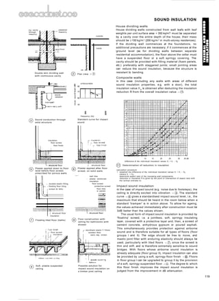

![VIBRATION DAMPING
Sound Conduction Through Structures
Vibrations in solid bodies, 'structure-borne sounds', are
created either by sound in air, or directly, by mechanical
excitation ~ CD + @.
Since the alternating mechanical forces are usually
higher than any produced by fluctuating air pressure, the
audible radiation is usually greater in the case of direct
excitation. Frequently, resonance phenomena occur, which
lead to higher audible radiation in narrow frequency ranges.
If the radiated sound remains monotonic, the cause is
usually the result of direct excitation of the structure. Anti
'structure-borne sound' measures must therefore seek to
reduce this direct excitation and its further propagation.
Precautions to combat structure-borne sound transmission
In the case of water installations, only valves carrying
inspection symbols in accordance with group I or II should
be used. The water pressure should be as low as possible.
The water velocity plays a subordinate role.
Pipework should be attached to walls in accordance with
good practice, with surface loading mil ~ 250 kg/m2.
Baths and tanks should be installed on floating screed
and separated from walls. Walled enclosures should be
flexibly jointed to the primary walls. Wall-suspended WC
fittings cause direct excitation of the structure; however,
rigid fixing is unavoidable, so if necessary, elastic layers
should be introduced.
Water and drainage pipes must be fixed using elastic
materials and should not be in direct contact with the
structural wall.
Lifts should be installed in separate shafts ~ @ and joints
filled with at least 30 mm mineral fibre, or the top of the
shaft provided with Neoprene bearing strips -~ @.
Pumps and equipment must be installed on structure-
borne sound insulated foundations and elastically
connected.
Compensators are subject to tensile stresses, since the
internal pressure also acts on the longitudinal axis of the
assembly ~ @.
Rubber granulate panels are particularly suitable as
insulating material for foundations, due to their high
compressive strength. If required, impact sound insulating
materials of mineral fibre and plastic foam can be built in.
Cork and solid rubber are unsuitable, since these materials
are too stiff. The more the insulating materials are
compressed together under load, without being
overloaded, the better is the insulating effect.
With flat insulating materials, the loading must usually
be greater than 0.5 N/mm2. If this cannot be guaranteed,
then individual elements are required, effectively to add to
the weight of the equipment.
The insulating effect is also greatest here if the elements
are loaded to a maximum, without becoming overloaded.
The individual elements can be of Neoprene or steel >. @.
Steel springs provide the best structural sound
insulation, due to their low stiffness. In special cases, air
springs can be used. In the case of individual springs,
attention must be paid to the centre of gravity, to ensure the
elements are uniformly loaded -~ (1).
In the case of periodic excitation (e.g. due to oscillating
or rotating masses), the frequency of excitation must not
coincide with the natural frequency of the elastically
suspended system. Large motions result from the
reverberation which, in the case of elements with low
damping, can lead to structural failure --~ @. Particularly
high insulating properties may be obtained by using
doubled elastic suspensions) @. Unfavourable interaction
between foundations on floating layers can lead to a
reduction in insulation.
o
2 1.41
machine foot
angle anchorage
gypsum board panels
~~ b= o~1
~
0
'"
-- f- I
amplification r damping
.1 0.3 10L20 :0 10
+30
turning ratio
~ 10
+40
o
nickel-steel spring
Example of individual
spring element
-20
Top of shaft with Neoprene
bearing layer
a~
~ airborne
f sound
Example of vibration
mounting ceiling element
ceiling suspension
m
~
is +10
.~
~ +20
vibration
mounting
® Effect of elastic bearing
o
o Causes of structure-borne
sound
:::::::::::::::::::::::::=::::::::::::::::::::::::::::::
~ pipeline fixing
point
Alignment of spring with
centre of gravity
Separate lift shaft with
>30 mm mineral fibre lining
light wall - high excitation
Heavy wall - less excitation
:.:.:.:.:.:.:.:.:.:.:.:.:.:.:.:.:.:.:.:.:.:.:.:.:
® Double elastic suspension
for ventilator
(])
® Equipment installation with
elastic insert in foundation
o
121](https://image.slidesharecdn.com/neufert-arch-datacompress-231212110729-3be4aee5/85/neufert-arch-data_compress-pdfdataaaaaaa-124-320.jpg)
![ROOM ACOUSTICS
Requirements for rooms
(1) Reverberation time
The optimum value for reverberation time is dependent
on the particular use and room volume ~ @. In general,
reverberation time is frequency-dependent (longer at
low frequencies, shorter at high frequencies.) For f =
500 Hz, surveys have shown that approximations may
provide optimum values ~ @.
(2) Speech intelligibility
This is used to judge the degree of audibility of the
spoken word ~ @. It is not standardised, so various
terms - sentence intelligibility, syllable intelligibility,
evaluation with logatomes - are usual. In determining
the intelligibility of speech, a number of collectively
heard individual syllables of no significance (Iogatomes
such as lin and ter) are noted; the correctness is used to
make an assessment - a score of more than 70% implies
excellent speech intelligibility. Newer, objective,
methods make use of modulated noise signals (RASTI
method) and lead to reproducible results at low expense.
(3) Impression of space
This is determined by the reception of reflections with
respect to time and direction. For music, diffuse
reflections are favourable for sound volume, while early
reflections with delays of up to 80 ms (corresponding to
27 m path difference) with respect to the direct sound
promote clarity ~ @. Speech requires shorter delays (up
to 50 rns) so as not to degrade the intelligibility.
Room acoustic planning should ensure that optimum
audible conditions are created for listeners in rooms where
speech and music are to be carried out. Various factors
should be considered, of which the two most important are
reverberation time, and reflections (as a consequence of the
primary and secondary structure of the room).
(1) Reverberation time
This is the time taken for the decay of a noise level of
60dS after the sound source has been switched off. CD·
Evaluation is carried out over the range -5 to -35dB.
(2) Absorption surface
The absorption surface is determined by the amount of
absorbing material, expressed as an area having
complete absorption (open window):
A = as x S
where as is the degree of sound absorption from echo
chamber measurements, and S is the area of surface
portion.
The reverberation time is calculated from the absorption
surface from:
t = 0.163 x V + as x S (after Sabine)
(3) Echoes
When individual, subjectively recognisable peaks are
superimposed on a smoothly falling reverberation time
curve ~ CD, these are described as echoes ~ ~. Various
values of time and intensity apply as the echo criterion
for speech and music. Rooms devoted to music should
have a longer reverberation time, but are usually
regarded as less critical from the point of view of echoes.
300
unfavourable
reflection (or echo)
Reverberation times:
optimum range
® Table of specific volumes
purpose characteristic max.
volume volume
(m 3 per seat) (m 3 )
spoken 3... 5 5000
theatrical
work
multipurpose: 4...7 8000
speech and
music
musical 5... 8 15000
theatre
(opera, operetta)
chamber music 6... 10 10000
concert hall
symphony music 8... 12 25000
concert hall
rooms for 10... 14 30000
oratorios and
organ music
CD
room reverberation
function time (s)
speech cabaret 0.8
drama 1.0
lecture
music chamber 1.0 ..1.5
music
opera 1.3... 1.6
concert 1.7... 2.1
organ music 2.5 ... 3.0
- echo
20 40 60 80%100
syllable intelligibility, Vs
] IliI1 I ~1
Speech intelligibility
wV V /
". /
/
/
~'
,/
....... ",,'/
".
( o~?J. C ~~ 0~c ,/ ....
~~?J. 0( ~ ~ '"
,.- ,.- ....
o ~~'( ~~ "./-' v"'"
<:>'1 oc'(?J. ,..-
V 00 ?J.(l~~o<:>~ I ...... ,.----
.....
./'
".'" / V >- ~ I -
". ".". ~ ,..-'"
1,,/
/ ,/
V V vV ~eec;;
,/
""
,..-/ ;;>
.......
'" V V
V
,,- '" / ... ~
,,- / ........V
/
~/
.....
......, ~- _... OdS
" .."
5dS
r I{
~l
I
resonance ,
I '
~ "T
• , I
,
- reverberation
, time curve
, ,
,
3SdS
T .
~--l
..~ interference acoustic _
,
• oil
1--- ,I?!essure leve~---
, .... VI"" -y ' •AlNJIIr"
....
time--
1.0
0.9
0.8
102
2 3 5 103
2 3 5 10· 2 3 5 105
2 3 5 106
o Reverberation times: tolerance :t20% volume, V
100
%
S 3.0
2.5
t- 2.0
.~ 1.8
c 1.6
o
.~ 1.4
~
~ 1.2
o Echo criterion
G) Measurement of reverberation time
early, favourable reflections
(]) Reflection sequence in the room
122](https://image.slidesharecdn.com/neufert-arch-datacompress-231212110729-3be4aee5/85/neufert-arch-data_compress-pdfdataaaaaaa-125-320.jpg)


![specific connected load p' W/m2 for
100lx for height 3 rn. area> 100m2
and reflection 0.7/0.5/0.2
C> A --4j: 12W/m2
~ QT~ ~ 10W/m2
C>HME ~ 5W/m2
~TC -E- 5W/m2
~
~
4W/m2
TC-L '8E1
C:====::::a
~ 3W/m2
T26
CD
CD
Specific connected load p.
for various lamp types
o
@
83 oEEo EE 0
O® o©
OEEOEEOEEO
o
EB 0830 EE
o
10
Calculation of illuminance
for internal areas
correction factor k
height area reflection factor
H A(m 2 ) 070502 050201 000
bright medium dark
up to 20 0.75 0.65 0.60
3m 50 0.90 0.80 0.75
:;> 100 1.00 0.90 0.85
3-5m 20 0.55 0.45 0.40
50 0.75 0.65 0.60
:;> 100 0.90 0.80 0.75
5-7m 50 0.55 0.45 0.40
:;> 100 0.75 0.65 0.60
o Table of correction factors
example
room area A = 100m2
room height H = 3 m
reflection factor 0.5/0.2/0.1
(medium reflection)
type of light
p' = 4W/m2 • (compact fluorescent lamp)
p' = 9 . 45 W = 405 W
type of light
p' = 12W/m2 • (general purpose lamp)
p' =8· 100W = 800W
type of light
P" = 10W/m2 • (halogen filament lamp)
p' = 16 . 20 W = 320 W
formula
En = (1~g~~~5 + ogb~fg + 1~g~~fg).0.9
En = 180lx
LIGHTING: REQUIREMENTS
Calculation of mean illuminance
In practice, it is often necessary to obtain an estimate of the
mean intensity of illuminance (En) for a given level of
electrical power supplied, or the electrical power P required
for a given level of illumination. En and P can be estimated
from the formula in ~ @. The specific power P* required for
this calculation depends on the type of lamps used ~ CD,
and relates to direct illumination. The correction factor k
depends on the size of the room and the reflection levels of
the walls, ceiling and floor ~ (2).
If the calculation is to be made for rooms with different
types of lighting, the components are calculated
individually and then added together ~ @.
Calculation of the illumination using the specific power
is also applicable to offices. In the example, a rectangular
room with an area of 24 m2 is equipped with 4 lights. From
~ @, with 2 x 36W lamps (connected value, including 90W
ballast), an illuminance of ca. 3751x is achieved.
In offices, in addition to conventional louvred mirror
lighting, square louvred lighting with compact fluorescent
lamps ~ ([), or structured lighting ~ @, are frequently
installed. Lighting structures use a combination of power
supply rails to carry spotlights.
Floodlighting buildings
The luminous flux required for lamps used to floodlight a
building can be calculated from the formula in -4 @. The
luminance should be between 3cd/m2 (free-standing
objects) and 16cd/m2 (objects in very bright surroundings).
6.00m -
- - r - -- -
~
<,
2.50m
E
~
8
..
~- -- -
~
o Calculation for offices
® Built-in louvred lighting
A = 24m2
K = 0.75
(bright reflection)
= 4 . 90 W = 360 W
En = 1020;.~' 90 .0.75
En =3751x
l_--
T26 2 X 36W
= En' p. p'. 1
100 k
Inn
100
En nominal illuminance (Ix)
p connected load (W)
p' specific connected load (W/m2) ~ CD
A room floor area
k correction factor ~ (2)
® Formula for mean illuminance En and connected load P
® Structured lighting
6.00m ~
6.00m ~
- -EB-
--.[ <;
I 250m I~
E
~
8
..
~.
-$-.- -ifJ
T26 58W
TC-L 2 X 24W
calculation formula
for luminous flux
It· L· A
<1>=~~-
118· Q
luminance for a floodlit
object (cdrn-) L
free standing 3 - 6.5
dark surroundings 6.5 -10
moderately bright 10 -13
surroundings
very bright surroundings 13 -16
lighting efficiency factor
object 118
large area 0.4
small area
large distance 0.3
towers 0.2
<1> = luminous flux required
L = mean luminance (cd/mz)
A = surface to be floodlit
118 = lighting efficiency factor
Q = reflection factor for the material
level of reflection from
illuminated materials Q
brick, white vitrified 0.85
white marble 0.6
plaster, light 0.3-0.5
plaster, dark 0.2-0.3
light sandstone 0.3-0.4
dark sandstone 0.1-0.2
light brick 0.3-0.4
dark brick 0.1-0.2
light wood 0.3-0.5
granite 0.1-0.2
(]) Built-in louvred lighting ® Luminous flux required for floodlighting
147](https://image.slidesharecdn.com/neufert-arch-datacompress-231212110729-3be4aee5/85/neufert-arch-data_compress-pdfdataaaaaaa-150-320.jpg)


![1 artificial sun with parabolic
reflector or similar
2 model: e.g. for city buildings,
architecture
3 simulator to represent
variations in time of day, time
of year and latitude
DAYLIGHT
:.:.:.:.:.:.:.:.:.:.:.:.:.:.:.:.:.:.:.:.:.:.:.:.:.:.:.:.:.:.:.:.:.~.:.:.:.:.:.:.:.:.:.:.:.:.:.:.:.:.:.:.:.:.:.:.:.:.:.:.:.:.:.:.:.:.:.:.:.:.:.:.:.:.:.:.:.:.:.:.:.:.:.:.:.:.:.:.:.:.:.:.:.:.:.:. :.:.:.:.:
@ Artificial sun model
Position of the sun: shadows, methods employed
The following methods are employed to determine and
verify the actual solar radiation and shadow, both inside
and outside buildings, as a function of geographical
location, time of year and time of day, structural features
and surrounding conditions.
Graphical construction of shadows. Determination of the
shadows cast by a building can be accomplished using the
projected (apparent) course of the sun, represented in ~ ®
(see previous page), by means of a plan and an elevation.
As an example, the shadows in a courtyard in Brighton,
latitude 51°N, will be constructed for 21 March, at 16.00. The
sun appears at this time at an azimuth angle (as1) of 245°
and an elevation (Ys1) of 20° ~ ® + @. The positional plan is
orientated with the north. The directions of the shadows are
determined by the horizontal edges of the building, that is,
a parallel shift of the direction of the sunshine (as 1 = 245°)
due to the corners of the building. The length of the shadow
is determined by the vertical edges of the building, that is,
a rotation of the true height of the building (h) and
application of the elevation angle of 20°. The point of
intersection with the direction of the shadow gives the
length of the shadow.
Panorama mask. In many countries, a representation of the
path of the sun is available for various geographical areas.
These representations are printed on clear film, and include
data on azimuth and elevation angles, as well as time of
year and time of day. In use, a copy of the relevant sheet is
bent in a curve and positioned in the direction of the sun
~ @. By looking through the panorama mask, any
encroachment of shadows from the surroundings and from
overhead shadows is transferred to the printed path of the
sun, on a scale of 1:1 ~ @. The film can then be used to
analyse the occurrence of shadows and sunshine on
facades and on sections of buildings to the correct scale.
Horizontoscope. The horizontoscope is an aid to
determining the true conditions of sunshine and shadow on
building sites and on and in buildings. The horizontoscope
consists of a transparent dome, a compass, the base and
exchangeable curved sheets which are placed on the base,
according to the task in hand, to investigate light, radiation
or heat, etc.
The purpose of the horizontoscope is to construct the
light and shade conditions which exist in a room, e.g. ~ @.
At a particular point in the room, the opening for incident
light can be assessed by means of a window cut-out
projected on the dome and at the same time on the curved
sheet underneath. It is therefore possible to determine both
the radiation conditions and light effects in the room for
each point in the room, and for any time of day and time of
year, depending on the alignment of the building ~ @.
Model simulation. In order to simulate and establish
accurate annual shadow and solar radiation effects in and on
a building, it is possible to construct a true-to-scale model
and to test it under an artificial sun (parallel light) ~ 0].
window
projection
schematic
section
t
west
t
south-west
"t
south
panorama mask
shift of central axis from 0° 45°
t
south-east
t
compass
inner
court
n=
14cm diameter base
with compass
Possible course of shadows on the film
dome, height 3cm
(transparent)
exchangeable
curved sheets for
sun, heat, light,
radiation etc.
positional
plan
:il~~ation 10 ~, D
:.:.:.:.:.:.:.:.:.:.:.:.:.:.:.:.:.:.:.:.:.:.:.:.:.:.:.:.:.:.:.:.:.:.:.:.:.:.:.:.:.:.:.:.:.:.:.:.:.:.:.:.:.:.:.:.:.:.':"':':.:.~:.:.~:.:.~:.:.~:.:.~:.:~.:.:~.:.:~.:.:~.:.:~.:.:~.:.:~.:.:~.:.:"".:••
""
••
:."":.:."":.:."":.:."":.:."":.:."!"!:.:
@
@ Graphical shadow construction
153](https://image.slidesharecdn.com/neufert-arch-datacompress-231212110729-3be4aee5/85/neufert-arch-data_compress-pdfdataaaaaaa-156-320.jpg)


![DAYLIGHT
Brightness, window sizes and visual links
The position, size and type of windows essentially
determine the pattern of daylight in an internal area ~ @.
The appropriate window sizes for living and work rooms of
various dimensions are defined in ~ @. The following
conditions provide the basis for these calculations for living
rooms:
• 00/0 = 0.9 at the centre of a living room and at the
lowest point in a workroom,
• width of window = 0.55 x room width,
• clouded sky,
• reflection from the wall = 0.6,
• reflection from the ceiling = 0.7,
• reflection from the floor = 0.2,
• light losses from the glass = 0.75,
• light losses from window-frame scatter k1 = 0.75,
• light losses from contamination k2 = 0.95,
• reflected light from neighbouring buildings Dv = 0.2,
• angle of light reflected from neighbouring buildings a
= 0-50° (see ~ ® + @).
Note: This applies by analogy to workrooms when their
dimensions correspond to those of living rooms:
• room height (h) ~ 3.50 m,
• room depth (t) ~ 6 m,
• room area (A) ~ 50 m 2.
Visual links with the outside also demand the reqursite
window dimensions for living rooms and workrooms.
Minimum recommended requirements are summarised in
~ @ and ~ @. These recommendations contain the
following points:
• limiting clearances and clearance areas for the
relevant building heights must be maintained,
• visual link with the outside is a requirement for all
accommodation;
• as a rule, a window size of approx. 1/8-1/10 of the
usable room area must be provided for living rooms.
Among other factors in the town planning interpretation of
building instructions and standards, incident light, building
separation, the external aspects of neighbouring buildings
and window design all have to be taken into account ~ @.
For example, a building separation of 8 = 2H (~ 27°) is the
desired value. This results in an aperture angle of ~ 4°
(limited by building geometry and neighbouring buildings)
to achieve the minimum level of daylight in rooms.
Newly developed town planning schemes should be
carefully checked for the quality of light in internal areas
since, in general, the building regulations and standards
only set minimum requirements.
It is advisable to carry out a visual inspection of the
designs to check the expected appearance of internal and
external areas, either in model form, under an artificial sun
and artificial sky, or using an endoscope device.
workroom
tp P
t-l
l,()
co
o
io
<Xl
o
section
tv (B)
1-----+----1 EB ~-+--~
1-----+----1 EE ~-+--~
I~~~ I ~ IEB ~--+------l
plan
+--
cloudy sky
room height h
window height hF - -
room depth t
room width b
influence of
adjacent building
ex = 0°
Determination of the required window widths (ww) with different
room dimensions and interference from various adjacent building
(extract)
living rooms workrooms
c > 2.20m as for living with h < 3.50 m with h > 3.50 m
hs o.so.» rooms, if: window area c-h s::>1.30m
bf ' 0.55 • b h "2.50m > 30% of hs <:: o.so »
minimum t < 6.0m b x h bF ::> 0.55 • b
requirement A <, 50m 2
@ Diagram to determine the window widths required
window width (ww) (m)
@ Various daylight patterns in an internal area with different
vertical window positions
H
B = 2H good
aperture
angle >4°
B
------~------
angle of
incident
light> 2]0
I
visual inspection
of model
;:;:;:;::::::::::::::::::::::::::::::::::::::::::::::::::::::::::::::::::::::::::::::::::;:::::::::::::::::::::::::
@ Incident light and building separation
@
workroom
for t . 5m F" 1.25m2
for t > 5 m F " 1.5 m-'
rF = 0.1 • A for A <, 600 m-'
fF = 60 + 0.01 A for A > 600 rn-'
required window sizes in workrooms
,0.55· b
· 0.1· A/m2
· 0.3· Af
· 0.16· A
· 0.07 • A • h/rn'
Window requirements in living rooms
@ Recommended visual links with outside
@ Summary of visual links with outside and window sizes
158](https://image.slidesharecdn.com/neufert-arch-datacompress-231212110729-3be4aee5/85/neufert-arch-data_compress-pdfdataaaaaaa-161-320.jpg)


![height of overhead illumination, room height and the uniformity of lighting which is sought
showing the corresponding overhead light arrangements in the roof area (ke factor)
@ Recommended values for the ratio Dmin/Dmax
Rooflighting
DAYLIGHT
Rooflights arranged at points on the ceiling area generate
typical minimum and maximum brightnesses in the region
where the light is required, the work plane. The mean value
between these 'bright' and 'dark' areas is calculated, and
this is termed the mean daylight factor Dm.
Thus, Dm is the arithmetic mean between Dmin and
Dmax with respect to the reference or work plane (0.85 m
above floor level). The required G ~ 1:2 is not based on
Dmax, but on Dmin, since unevenness in the daylight from
above is sensed physiologically as 'stronger than contrast'.
At this uniformity (Drnin = 1 and Dm = 2), Dmin must be ~
20/0 (compare ~ @).
Furthermore, the quality criteria striven for in controlling
the overhead daylight in the room are limited by the room
height and the shape of the rooflight (ke factor).
An ideal uniformity is achieved when the spacing
between the rooflights (0) is equivalent to the room height
(h), i.e. a ratio of approximately 1:1.
In practice the rule is that the ratio of rooflight spacing to
room height should be 1:1.5-1:2 (see ~ C@). This figure
contains a table from which these ratios and their effects
can be obtained. The figure also provides a
recommendation for the light shafts which should be let
into the roof.
......
"" r-,
~
'"
"""
0.4
0.6
Ky
1.0
0.8
(b) Diminution factor ky as a function
of the inclination y of the glazing in
shed roofs
daylight factor
(TQ)
10
20
15
[m]
(a) Comparative variations in the
daylight factor for side and
overhead illumination with various
inclinations of the rooflights
ratio
ke value = O/h
recommen-
~I~~
Dmin:Dmax dation 0= h·ke
:pprox.1:1 ' ~ { < 1 . .. 1.1 0 I
target II[ ]I
~
values
~~d1!
1.2 1.3 1.4
1:1.5
~ tolerable 1.4 1.5 1.7
1:2
~
h
critical 1.6 1.8 2.0
1:2.5
~ avoid 1.7 2.0 2.2
1:3
..:.:. ~. ~.... :.:.:.~. ~ ..:.:.:.:.!.~:.:.:.:.:.:.!: ~:.:.:
Type of rooflight and construction
The inclination of the rooflights determines the percentage
of the light component from the sky which is available. In ~
@a, the quantity of incident light admitted through a side
window is compared with the quantity of light provided by
rooflights at various inclinations. The greatest quantity of
light is received through a horizontal rooflight.
On the other hand, the maximum illuminance from a
side window is achieved only in the vicinity of the window;
for glazing which is vertically overhead, the lowest
illuminance is on the reference plane.
Thus there is a diminution factor (ky) for the quantity of
incident light which depends on the angle of inclination of
the rooflight. The diminution factors corresponding to shed
roofs of various inclinations are shown in ~ @b.
The diffuse incident light which falls on the rooflight is
affected by the construction and depth of the installation
before it supplies the room with daylight. The various levels
of incident light for shafts of different proportions beneath
rooflights the are shown in ~ @. Excessively high and
massive shafts and built-in depths should be avoided ~ C@a,
while a filigree, highly reflective construction is to be
recommended ~ @b.
The quality of daylight in an internal area with rooflights
is not only dependent on the factors discussed above.
Another significant factor is the ratio of the total area of the
overhead lights to the floor area of the room (kF factor).
The diagrams in ~ @ show the levels of daylight from
side windows with various geometrical features and
overhead illumination.
In order to increase the daylight factor Dmin by 50/0 for
side windows or opposite-facing rooflights, the proportions
of the windows must be increased significantly, typically up
to a ratio of 1:1.5. By contrast, for the same demands from
overhead lighting, particularly with shed roof-type lights,
the area need only be increased by a relatively small
amount. A ratio of rooflight area to floor area of from 1:4 to
1:5 is adequate.
Additional diminution factors for rooflights are given
below.
• transmittance of the glazing, t
• scatter and constructional features, k1
• soiling of the glazing, k2
• diffuse illumination, k3.
(b) Uniform illumination in the internal
area and hence better daylight
conditions from rooflights with a
lighter, filigree lower structure, with
good reflection characteristics
0.2
~
10 -: I
8=::;::>"~'=:
0.25
~
10 I I
5 I c===> <=> I
oI I
~-10
~80.6
kF = window area/floor area = 1.6
values required for Dmin = 5% are shown for comparison
Effects of different windows and rooflights on the variation in
the daylight factor in a room with fixed principal dimensions
1 with horizontal rooflight; no shaft, i.e. h ;:: 0
- --- 2 with a light shaft; h ;:: a
- .- - 3 with a light shaft; h ;:: 2a
side windows and 0 0 rooflights + shed
opposite-facing ~Yf D _~~A roofs + inclined
rooflights or - 0 shed roofs
30+-~~~~~::::;::::~~==1l
25
20
15 4--#--+--:~4--~~--+-~-+---I1
10
5 +-i+-~"-2--.i~t-----i---f~~-:+-:-:t I -.
(m]
(a) Reduction in the quantity of
daylight with overhead lighting with
deep aperture shafts and bulky
lower structures
162](https://image.slidesharecdn.com/neufert-arch-datacompress-231212110729-3be4aee5/85/neufert-arch-data_compress-pdfdataaaaaaa-165-320.jpg)


![A
welded
edges
full glass edge with two panes
welding
G) Multi-pane glazing units
with three panes
GLASS
Doublerrriple Glazing
Multi-layered, insulating glazing units are manufactured out
of two or more sheets of glass ~ CD (clear float glass, tinted
and coated glass, rough cast and patterned glass) separated
by one or more air- or gas-filled cavities. Multi-layered
glazing units can, depending on the assembly, provide high
thermal and/or sound insulation (e.g. sound-reducing units,
solar protection units, heat-absorbing units, laminated
glass with intermediate layers). There is dried air or a
special gas in the spaces between the glass sheets.
Different edge treatments define three types of units: full
glass edge welding ~ CDA; edges welded together with
inserts ~ CDs; glued organic edge sealing ~ CDc.
build-up OPTIFLOAT (mm) 4 4 4 5 5 5 4 4 4 5 5 5
cavity width (mm) (8.5) (8.5) (8.5) (8,.5) (6) (6) (6) (6)
k value (W/m2K ) 1.9 1.9 2.0 2.0
light transmittance (%) 74 72 74 72
unit thickness (rnrn) 29 32 24 27
max. edge length (em) 141 x 240 180 x 240 141 x 240 180 x 240
min. size (crn-'] 24 x 24 24 x 24 24 x 24 24 x 24
aspect ratio 1:6 1:6 1:6 1:6
max. area (m 2) 3.4 3.4 3.4 3.4
weight (kg/m2) ca. 30 ca. 38 ca. 30 ca. 38
thickness tolerance: -lmm size tolerance: ±2.0 mm
+2mm
® Triple glazing
® Double glazing
cavity double glazing k
width with 2 x OPTIFLOAT float glass (W/m2K)
4mm 5mm 6mm 8mm 10mm 12mm
width (em) 141 185 185 300 300 300
height (em) 240 300 500 500 500 500
8 surface area (m 2) 3.4 5.5 9.2 15.0 15.0 15.0 3.2
aspect ratio 1:6 1:10 1:10 1:10 1:10 1:10
overall thickness (mm) 16 18 20 24 28 32
width (em) 141 245 280 300 300 300
height (em) 240 300 500 500 500 500
10 surface area (m 2) 3.4 7.3 14.0 15.0 15.0 15.0 3.1
aspect ratio 1:6 1:10 1:10 1:10 1:10 1:10
overall thickness (rnrn) 18 20 22 26 30 34
width (em) 141 245 280 300 300 300
height (em) 141 245 280 300 300 300
12 surface area (rn-') 3.4 7.3 14.0 15.0 15.0 15.0 3.0
aspect ratio 1:6 1:10 1:10 1:10 1:10 1:10
overall thickness (mrn) 20 22 24 28 32 36
thickness tolerance (mm) ± 1.0 ± 1.0 ± 1.0 ± 1.0 ± 1.0 ± 1.0
size tolerance (rnrn) ± 1.5 ± 2.0 ± 2.0 ± 2.0 ± 2.0 ± 2.0
weight (kg/m2) 20 25 30 40 50 60
~
triangle
I A I
segmental arch
~
BIBrE
~A-----i
polygon
l--- A-----J
rounded corners
~
semi-circular
wIB
t---A----i
semi-circular
A
polygon
A
min 50cm fA
max. 200 em
@
~IB
I------A--------J
rounded corners
e
segmental arch
circle
~A--------J
polygon
right-angled triangle
o Heat transfer with single, double and triple glazing
I---+-~D_---li .s, ~
B[~Ic B[B B[BB[~rD
t-----~ I A I I A Ie ~
one slanting edge trapezium parallelogram polygon
:101DB[~DlcI~[B'~~I
~
r~ ciO~IB
~ ~------1
o Manufactured glazing units, possible shapes
recommended glass
thicknesses for inside
and outside panes of
double glazing up to
20.00 m installation
height (wind load =
1.2kN/m2 or 1200Pa)
50
75 ~
Q)
100 -g
125 ~
150 u,
~
--
~~
"~r-..I---.
"'F::::
-
r---~
-
<, ------I~
r-,
==
-r,- I~i'--...
---
----t- --- -~
'""--
--t-~ ~ --I'"--
............
'<,I'--. 250
300
width, long edge (em)
o 50 100 150 200 250 300 350 400 450 500
o
50
75 ~ recommended glass
thicknesses for inside
100
Q)
and outside panes of
E
en
-g double glazing up to
E 5
125
~
8.00 m installation
height (wind load = r.Il
150
r.Il 6
0.75kN/m2 or 750Pa)
Q)
c
.i
~
7
200 o
en ~
250 ~ r.Il 8
r.Il
ro
0> 9
.- -,--~ -_.
-::::~
e-;
~~~
~
t::::::r---I----
>-.~ -
"~
r--- -
f---- -
~
f---
"""--
r--
-
f---- - - ~ -
-
"~i'-
---
300
width, long edge (em)
o 50 100 150 200 250 300 350 400 450 500
o
E
E 4
r.Il
~ 5
o 6
~
~ 7
0>8
o Recommended thicknesses, 8 m high glass o Recommended thicknesses, 20 m high glass
166](https://image.slidesharecdn.com/neufert-arch-datacompress-231212110729-3be4aee5/85/neufert-arch-data_compress-pdfdataaaaaaa-169-320.jpg)


![GLASS
Glass entrance screens consist of one or several glass
doors, and the side and top panels. Other possibilities are
sliding, folding, arched and half-round headed entrance
screens. Various colours and glass structures are available.
The dimensions of the doors are the same as those of the
frame ----t @ - @. When violently smashed, the glass
disintegrates into a network of small crumbs which loosely
hang together. Normal glass thicknesses of 10 or 12mm are
used, and stiffening ribs may be necessary, depending on
the structural requirements.
DIT] rn[]]]
OJ [ill [}] ITIIJ
~ ED [] rn rn[ill[ill
OJErn[ill ffiJrrrn
[ill[ill [ffi][ill
DLDJ rnm
D[ill rn[ill]
Double-leaf doors
o Single-leaf doors
glass pattern colour thickness double-glazing max. max.
unit aspect size
ratio
structure with
12mm
(mm) direction side cavity (ern)
old German yellow, clear 4 x. 1:6 150 x 210
old German K, clear, yellow,
short side >250mm bronze, grey 4 x '>. 1:6 150 x 210
ox-eye glass yellow, clear 6 x 0 1:6 150 x 210
chinchilla bronze, clear 4 . x 1:6 156 x 213
Croco 129 clear 4 x, x 1:6 156 x 213
Delta clear, bronze 4 x x 1:6 156 x 213
Difulit 597 clear 4 X x 1:6 150 x 210
wired Difulit 597 clear 7 x x 1:10 150 x 245
wired glass' clear 7 x x 1:10 186 x 300
wired glassI clear 9 x x 1:10 150 x 245
wired optical clear 9 x 0 1:10 150 x 300
wired ornamental 187
(Abstracto) clear, bronze 7 D 0 1:10 180 x 245
wired ornamental 521, 523 clear 7 x 0 1:10 180 x 245
wired ornamental
Flora 035 + Neolit clear 7 . x 1:10 180 x 245
Edelit 504,
one or both sides clear 4 . x 1:6 150 x 210
Flora 035 bronze, clear 5 .1 x 1:6 150 x 210
antique cast yellow, grey, clear 4 x x 1:6 150 x 210
antique cast 1074,1082,1086 grey 4 x x 1:6 126 x 210
Karolit double-sided clear 4 . x 1:6 150 x 210
cathedral large and small
hammered clear 4 x ». 1:6 150 x 210
cathedral 102 yellow 4 x x 1:6 150 x 200
cathedral 1074, 1082, 1086 grey 4 x x 1:6 150 x 210
basket weave clear, yellow 4 .1 0 1:6 150 x 210
beaded 030 clear 5 .1 x 1:6 150 x 210
Listral clear 4 .1 0 1:6 150 x 210
Maya clear, bronze 5 x 0 1:6 156 x 213
Maya opaque clear, bronze 5 x 0 1:6 156 x 213
Neolit clear 4 .1 0 1:6 150 x 210
Niagra yellow, bronze, clear 5 /! 0 1:10 156 x 213
Niagra opaque clear 5 .1 x 1:10 156 x 213
ornament 134 (Nucleo) bronze, clear 4 .1 x 1:6 150 x 210
ornament 178 (SilviO bronze, clear 4 .1 X 1:6 150 x 210
ornament 187 (Abstracto) yellow, bronze, clear 4 D 0 1:6 150 x 210
ornament 502, 504, 520 clear 4 x x 1:6 150 x 210
ornament 521,523 clear 4 x 0 1:6 150 x 210
ornament 523 yellow 4 x x 1:6 150 x 210
ornament 528 clear 4 x 0 1:6 150 x 210
ornament 550, 552, 597 clear 4 x x 1:6 150 x 210
patio bronze, clear 5 . 0 1:10 156 x 213
hammered crude glass clear 5 x x 1:10 186 x 300
hammered crude glass clear 7 x x 1:10 186 x 450
Tigris 003 clear 5 .1 x 1:6 150 x 210
Ii = structured surface either way x = structured surface either side
. = structured surface vertical = structured surface outside only
1) wired glass in rooflights, max. aspect ratio 1:3
G) Cast glass combinations
The term cast glass is given to machine-produced glass
which has been given a surface texture by rolling. It is not
clearly transparent ----t CD. Cast glass is used where clear
transparency in not desired (bathroom, WC) and where a
decorative effect is required. The ornamental aspects of
cast glass are classified as clear and coloured ornamental
glass, clear crude glass, clear and coloured wired glass, and
clear and coloured ornamental wired glass. Almost all
commercially available cast glass can be used in double-
glazing units ~ CD.
Normally, the structured side is placed outside in order
to ensure a perfect edge seal. So that double-glazing units
may be cleaned easily, the structured side is placed towards
the cavity. This is possible only with lightly structured glass.
Do not combine coloured cast glass with other coloured
glasses such as float, armoured or laminated glass, or with
coated, heat-absorbing or reflective glass.
glass type nominal tolerance max. dimensions
thickness
(mm) (mm) (ern x cm)
agricultural glass
3 ±0.2 48 x 120 73 x 143
46 x 144 73 x 165
(standard sizes)
4 ±0.3 60 x 174 60 x 200
size I size II size III
standard door leaf,
709 x 1972 rnrn- 834 x 1972 rnrn-' 959 " 1972 rnrn-'
overall dimensions
frame rebate
716 x 1983mm2 841 x 1983 mm? 966" 1983mm2
dimensions
structural
750 x 2000 mrn? 875 x 2000 rnm? 1000 x 2000 mm-'
opening sizes
special sizes are possible up to dimensions of:
1000 x 2100mm 2
1150 x 2100 m m 2
o Glass doors. standard sizes
glass type glass maximum thickness
thickness sizes tolerances
(mm) (mm-'] (mm)
clear, grey, bronze 10 2400 x 3430
± 0.3
12 2150 X 3500'
OPTIWHITE® 10 2400 x 3430
± 0.3
10 2150 x 3500'
structure 200 10 1860 x 3430
± 0.5
10 1860 x 3500'
bamboo, chinchilla 8 1700 x 2800
± 0.5
clear/bronze 8 1700 x 3000'
o Agricultural glass ® Glass entrance screens (side and top panels)
170](https://image.slidesharecdn.com/neufert-arch-datacompress-231212110729-3be4aee5/85/neufert-arch-data_compress-pdfdataaaaaaa-173-320.jpg)

![G) Profiled glass - sections
height from
r-L..., LL-J II t II
ground level
to top of up to up to up to up to up to up to up to up to up to
glazed opening 8m 20m 100m 8m 20m 100m 8m 20m 100m
glass type -7 CD L" L" L" L" L" L" L" L" L"
NP2 3.25 2.55 2.20 4.35 3.45 2.95 4.60 3.65 3.10
K22/41/6
NP26 3.05 2.40 2.05 4.10 3.25 2.75 4.35 3.45 2.90
K25/41/6
NP3 2.75 2.20 1.85 3.70 2.95 2.50 3.90 3.10 2.65
K32/ 41/6
NP5 2.30 1.80 1.55 3.05 2.40 2.00 3.25 2.55 2.15
K50/41/6
SP2 5.15 4.05 3.45 6.65 5.45 4.65 7.00 5.75 4.90
K 22 /60/7
SP26 4.85 3.85 3.25 6.55 5.15 4.40 6.90 5.45 4.65
K 25/60/7
K 32/60/7 4.40 3.45 2.95 5.85 4.55 3.90 6.20 4.90 4.15
(a) single bends as sections of a
circle with and without straight
sections
(b) double or multiple bends with
identical or different radii
(c) sine curve bends
(d) 'S' bends
(e) 'U' bends with or without
straight sections
j
01
=J~
I IAII A == nominal unit
H L dimension plus joint
II I
B == overall frame width
C == overall frame height
.1 ~I L == length of glass
~ _ J_ == units of 25cm
~2.5 indication of
65 (85) width and height
width B == n.A + 5cm
height H == L + 4cm
nominal size
t-----------f
A
IT!: nU :E
double-glazed
[], U
0
single-glazed
55 (60) 55 (60)
~ ~25
Q!~~I"~L-~;;;;;;;;; ;;;;;;;;:::J!J~I~I~~~ ] 65(85)
~~ 2 A ~ ~ 2 A 2.5
B
GLASS
Profiled glass is cast glass produced with aU-shaped
profile. It is translucent, with an ornamentation on the
outside surface of the profile, and conforms to the
properties of cast glass.
Low maintenance requirements. Suitable for lift shafts
and roof glazing. Rooms using this glass for fenestration
are rendered dazzle-free.
Special types: Profilit-bronze, Cascade, Topas, Amethyst.
Heat-absorbing glass Reglit and Profilit 'Plus 1.7' attain a k
value of 1.8 W/m2K.
Solar-control glass (Type R, 'Bernstein'; Type P, 'Antisol').
which reflects and/or absorbs ultra-violet and infra-red
radiation, can be used to protect delicate goods which are
sensitive to UV radiation. The transmission of radiant
energy into the room is reduced, as is the convection from
the glazing, whilst the light transmission is maintained.
For glazing subject to impacts, e.g. in sports halls,
Regulit SP2 or Profilit K22/60n without wire reinforcement
shou Id be used.
Regulit and Profilit are allowed as fire-resistant glass A
30. Normal and special profiles are also available reinforced
with longitudinal wires.
o Bent forms
® Building dimensions
up to 89%
up to 81%
up to 29 dB
up to 41 dB
up to 55 dB
k == 5.6W/m2K
NP k == 2.8W/m2K
SP k == 2.7 W/m2K
L == length of glass units (m)
711
218
117
Isp2 I 160 K 22/60/7
232
711 248
117
Isp26 I 160 K 25/60/7
262
711
317
117
I I 160 K 32/60/7
r----- 331
NP/ SP =Reglit
K =Profilit
single-glazed
double-glazed
single-glazed
double-glazed
triple-glazed
single-glazed
double-glazed
486
sound reduction
thermal insulation
light transmittance
K 50/416
6 1+----- ~--~- --------+16
INP5 , 141
f- -~-------t
611
220
116
INP2
,141 K 22/41/6
232
I
611
250
.16
INP26 1141 K 25/41/6
~-~
262 --~
011
319
il6
INP3 1141 K 32/41/6
331 --4
h/a == 0.25; -(1.5 o q ) H/a == 0.5; -(1.7 o q )
height from ,-----'L---, LL-J cb ,-----'L---, LL-J cb
ground level
to top of up to up to up to up to up to up to up to up to up to up to up to up to
glazed opening 8m 20m ~OOm 8m 20m 100m 8m 20m 100m 8m 20m 100m
glass type ~ CD L" L" L" L" L" L" L" L" L" L" L" L"
NP2 2.60 2.10 1.75 3.75 2.95 2.50 2.45 1.95 1.65 3.50 2.75 2.35
K22/41/6
NP26 2.50 1.95 1.70 3.50 2.80 2.35 2.35 1.85 1.60 3.30 2.65 2.20
K25/41/6
NP3 2.20 1.75 1.50 3.15 2.50 2.15 2.10 1.65 1.45 2.95 2.35 2.00
K32/41/6
NP5 1.85 1.45 1.25 2.60 2.10 1.75 1.75 1.35 1.15 2.45 1.95 1.65
K50/41/6
SP2 4.20 3.30 2.80 5.95 4.65 3.95 3.95 3.10 2.65 5.55 4.40 3.70
K22/60/7
SP26 3.95 3.10 2.65 5.60 4.40 3.80 3.70 2.90 2.60 5.25 4.15 3.55
K 25/60/7
K32/60/7 3.60 2.80 2.40 5.00 4.00 3.40 3.35 2.65 2.25 4.75 3.75 3.20
o Physical data
o Exposed buildings
CD Sheltered buildings (0.8 - 1.25 g)
FIHMI
G~f~~
practical examples of possible bent forms using ornamental glass
. unfolded
H r L- :=lli, ,li"L. "21
E-I == double-glazed, alternative forms
® Possible combinations
Mr-----rr---l1
A == single-glazed, flange external
rIlfITrIl1
B == single-glazed, flange internal
fIj-11 r-
C == single-glazed, flange external and internal
r----frITl11
D == single-glazed, flange alternating
~
172](https://image.slidesharecdn.com/neufert-arch-datacompress-231212110729-3be4aee5/85/neufert-arch-data_compress-pdfdataaaaaaa-175-320.jpg)


![WINDOWS: SIZES
If daylight is considered to be essential for the use to which
a room will be put, then windows are an unavoidable
necessity. Simple apertures for daylight have developed
into significant stylistic features, from Romanesque semi-
circular arched windows to Baroque windows surrounded
by rich, elaborate decoration. In the European cultural
region lying north of the Alps, window forms reveal
particularly strong features. In contrast to the climatically
favoured cultural region of the Mediterranean, daily life
here mainly had to be spent indoors. The people were thus
dependent upon daylight because artificial light was
expensive and good illumination of a room during the
hours of darkness was beyond the means of most of the
local population.
Every work area needs a window leading to the outside
world. The window area which transmits light must be at
least 1/20 of the surface area of the floor in the work space.
The total width of all the windows must amount to at least
1/10 of the total width of all the walls, i.e. 1/10 (M + N + 0 + P)
~ CD·
For workrooms which are 3.5 m or more high, the light
transmission surface of the window must be at least 300/0 of
the outside wall surface, i.e. ~ 0.3 A x B ~ 0.
For workrooms with dimensions similar to those of a
living room, the following rules should be applied.
Minimum height of the glass surface, 1.3 m ~ @.
Height of the window breast from the ground, ~ 0.9 m.
The total height of all windows must be 500/0 of the width
of the workroom, i.e. Q = 0.5R ~ @.
B
(3) Window stze > 0.3 A x B
I
clear window aperture
t
T
~ 130
1
glass area = 1/20 of room area
window width = 1/10 (M + N + a + PI
G) Window sizes for industrial
buildings
~. el b a
~ 30°- ~45°
el bl
~ a
C1J
u
c
~ i: 18°-:1 30°
--lbl ;Ia
.~
~AO ---- ----
a
C1J :ii 18·
mI
~
I
'??hJ I
6 ~c
5 10 15 20 25"10
c- window size as % of room floor area
When calculating the
window size for a living
room, both the floor area of
the room and the angle of
incidence of the light must
be taken into account ~ @.
Here, 'a' is the minimum
window size for a living
room as a percentage of the
floor area of the room, 'b' is
the minimum size for a
kitchen window and 'c' is
the minimum size for all
other rooms. The angle of
incidence of the light is 'd'.
The larger the angle of
incidence, the larger the
windows need to be. This is
because the closer the
neighbouring houses are,
and the higher they are, the
greater the angle of
incidence and the smaller
the amount of light
penetrating into the house.
Larger windows will com-
pensate for this smaller
quantity of light.
Dutch regulations stip-
ulate the sizes of windows
in relation to the angle of
incidence of the light.
Example ~ ®
A For a flat, angle of incidence of
light 18°-30°
B Necessary window size for the
living room
C 17% of the room floor surface area
is sufficient for the size of
the windows.
The slope of the roof surface
is known. A skylight with a slope
of 0° needs to be only 20% of the
size of a vertical window to make
the room equally bright - however,
there is no view. Windows are
generally the poorest point in
terms of heat insulation. For this
reason, it is convenient to fit the
room with smaller windows, as long
as the solar heat gain through the
windows is discounted.
As well as the window size and
the slope of the window surface,
the siting of the house plays an
important role. A free-standing
house admits more light with the
same surface area of windows than
a house in the city centre.
Example '® -([)
A Slope of a roof window of 40°
B The house is not free standing,
but is also not in heavy shadow
C 10% of the room floor surface area
is sufficient for the size of the
windows.
25
20
15
~
I
shady
workshop
o Width of the window
aperture Q ?: 0.5 R
® Window sizes in domestic buildings
o Section of fa~ade
+
~
~
0+
N L free
g ~ standing
'L-. position
j 0 / . _ A _
.~. ~
'0 ~
~~~
]o~ I
•~: ~ :c
o 5 10
• window size as % of room floor area
® Window sizes (j) Roof window
176](https://image.slidesharecdn.com/neufert-arch-datacompress-231212110729-3be4aee5/85/neufert-arch-data_compress-pdfdataaaaaaa-179-320.jpg)

![50-100
~
Protection measures must
prevent glare and regulate
the inflow of heat from
sunlight. In temperate
climates, large window
apertures with a high but
diffuse incidence of light
are preferred, whereas in
hot climates, small window
apertures still allow
sufficient light to enter.
Venetian blinds @
(with flat slats of wood,
aluminium or plastic), roller
shutters, roller blinds and
partially angled sun blinds
are all useful and can be
adjusted as required. Fixed
external devices are clearly
less flexible than retractable
or adjustable ones. Vertical
panel blinds ~ @ (either
fixed or pivoting around the
axis of the slat) are also
suitable for tall or angled
window surfaces.
Heat rising up the face of
a building should be able to
escape, and not be blocked
by external sun screens or
allowed to enter the
building via open skylights.
Internal shades are less
effective than external ones
for reducing solar heat gain
because the heat they
absorb is released into the
room.
.r.
Sloping awning with vertical
fringe
WINDOWS: SHADING
angles of sun 0.' and angle of shadow 0.
are given for a south wall at latitude 50°
north -. (f) - @
21 June (summer solstice), midday
u' = 63°; a = Z]"
1 May and 31 July, midday
a' = 50°; a = 40°
21 March and 23 Sept (equinox), midday
a l = 40°; a = 50°
In general, projection P = tg angle
of shadow a x height of window H;
at the very smallest projection,
P = (tg angle of shadow 0. x height of
window H) - wall thickness D.
®
o Roller shutter
® Partly angled sun blind
® Double sun shades
o External louvred blind
Awning keeps sun's rays
and heat at bay
Internal venetian blind: sun
comes through window
(not good)
mprojection:~
~::-~----------1
::::::::::::::j~ ~ 400 0 go
angle of sun IX' unob-
~/ / _~ structed
7 r view
a a:iofshadow•
wall thickness
/
PROTECTION FROM THE SUN
(j) Arrangement of single sun
shades
® Balcony or
window ledge
@ Wooden, AI or @ Double @ Angled
sheet steel sun sun shade shades
shades
@ Blind alignment gives
diffused light or shadow
effect
@ Sun-blocking
slats
Vertical
slats
@ Sun screen @ Partially
angled blind
@ Sloping and
vertical blind
Cantilevered
screen
Projecting
screen
® Adjustable awning
178](https://image.slidesharecdn.com/neufert-arch-datacompress-231212110729-3be4aee5/85/neufert-arch-data_compress-pdfdataaaaaaa-181-320.jpg)

![CD Pivoting windows (3) Top-hung windows; sliding
LOFT WINDOWS
In planning the size of windows, the optimum daylight level
relative to the purpose of the room must be the deciding
factor. For instance, building regulations require a
minimum window area of 1/8 of the floor surface area for
living rooms ~ GJ).
Large windows make living rooms more comfortable.
The window width in secondary rooms can be chosen
according to the distance between the rafters. Generously
wide windows in living rooms can be achieved by the
inclusion of rafter trimmers. Steeper roofs need shorter
windows, while flatter roofs require longer windows. Roof
windows can be joined using purpose-made prefabricated
flashing, and can be arranged in rows or in combinations
next to or above one another ~ @ + @
O
· · · · · ·T"'. · · · ·~ · · · ·~ · · · · · I~
...L-J...L-J... ..... U1
, ,
~ 1/
.s: 'E]-
-" ~----" ~--
.: "[g--~--,' §~u
" , ' " " , / / II ~ ::I::;
' " , "~I 1/ '" ; / " I / ~ .....I
. <.» ... / ... <,> ... ',~ (// "... ~ ~
~••..··~]~L
[1 [j, g:s,.••.........
. ' I . ' ... ," . . .
.............. . ..
plastic frame
pivoting
window
MIUqOM
bixonud
pivoting
window
double top-
hung/pivoting
window
pivoting
window
extra unit:
round arch
1
64 cm I
...............
escape windows
[J" 81
~ ..
"J
I '
: ", I
~I
/'1
~1
I
1/
' / I
''' ~ /
~1
:/' / .. ... . .
o Top-hung window with
vertical unit ~ @
>>~O » eO
~40 ~50
<> 30
~30
® Layout of roof windows
o Sliding windows; escape
@ Window sizes
@ Calculation of window size, in relation to floor area
~'.•'.~'.~•••~.~
vertical
window unit
~@
window size 54/83 54/103 64/103 74/103 74/123 74/144 114/123 114/144 134/144
surface area
of light
admission 0.21 0.28 0.36 0.44 0.55 0.66 0.93 1.12 1.36
(m 2)
room size (m 2) 2 2-3 3-4 4-5 6-7 9 11 13
2.00
r-)-::E-------::;:"~~-- 230
(j) With vertical unit
1201.1100
1401 120
185
1.90
® At the eaves
19
II
, I
19
r r r r r :» ,-----,
I I , I
I ' , I
I
19
II
19
II
115
~o 75
® Section of built-in options ® Horizontal section @ Row of windows with
vertical window units -t ® @ Adjacent to/above one
another](https://image.slidesharecdn.com/neufert-arch-datacompress-231212110729-3be4aee5/85/neufert-arch-data_compress-pdfdataaaaaaa-183-320.jpg)

![5l
§
~ 'g ~,~ .!!;::
Q)
~
~iii~ ~
II)
~~~'~
'g
~- ~a:=~
Q)
~,2'~ '0
i Q)a:'I
Ol~
~-g
i~
~~~E
c.ca ~,~'~ e
ca~
0 ~ 50 25 (30)
I 51-55 25 (30)
II 56-60 30 (35)
III 61-65 35 (40)
IV 6~70 40 (45)
V > 70 40 (45)
21 values in brackets apply to outside walls and
must also be used for windows if these form
more than 60% of the outside wall surface
@ Selecting sound insulation
Any window design must satisfy the technical
requirements of the relevant parts of the building. The
main considerations are the size, format, divisions, way of
opening, frame material and surface treatment.
Ventilation, thermal and sound insulation, fire resistance
and general safety issues, including the use of security
glazing, must also be taken into account. The design of the
sections and the location and type of sealing are of great
importance in guaranteeing a long-lasting water- and
draught-proof seal. Built-in components such as roller
shutter boxes, window sills and vents must match the
noise insulation of the windows ~ ® - @ as well as other
technical specifications.
WINDOWS: CONSTRUCTION
~~ II)
o ca Q)
~ 0
!L
Q) .s~
Q)
~~
~
c:
ca
0
(J~
'§'~ s ~
c:~ Q)
8-
~~§
>'c: ... II)
~ ~~ ~ 'g
residential < 10 0
street
two-lane <35 0
residential 2~35 10-50 I
street 11-25 II
~ 10 III
residential > 100 0
main road 3~100 I
(2 lane) 2~35 50-200 II
11-25 III
~ 10 IV
country road, 101-300
built-up area 1) 101-300 I
(2 lane) 3~100 II
residential 11-35 200-1000 III
main road ~ 10 IV
(2 lane)
urban main 101-300 III
roads, 3~100 1000-3000 IV
industrial >35 V
areas
main roads 101-300 IV
4 to 6 lanes
motorway ~ 100 3000-5000 V
feeder roads
and
motorways
11 apply the next highest noise level band for
surburban built-up areas and roads in
commercial areas
'.r: :~.~.:.:.:.:.:.~.:.:.:.:.:.:.:.:.:.:.:.:.:.:.: :.:.:.:.:.:.:.:.:.:.:.:.:.:.:.:.:.:
••••••••••i••••••••••••'.'•••••••••••••••••••••• • • • • • • • • • .
oAluminium thermally separated
composite casement window
(up to 47 dB)
CD·~~.CD.:~;~~·~~~~~·~;·I~:::·
separated profile sections
(up to 37 dB)
II
® Aluminium thermally separated ® Aluminium/timber combination @ How loud is it?
sliding window (up to 35 dB) casement window (up to 40 dB)
..................................................•..........................................
:.:.:.:.:.:.:.:.:.:.:.:.:.:.:.:.:.:.:.:.:.:.:.:.:.:.:.:.:.:.:.:.:.:.:.:.:.:.:.:.:.:.:.:.:.:.:.
o Universal aluminium window
into which a sun screen can
be fitted (up to 47 dB)
~
G) Aluminium windows with
flush mounted casements
IE G£] ~ ~ 500
EEl GE [ill ~ 600
lE ffi ~ ~ 700
B3 [fJ rn EEJ EE ttJ ~ 900
fB [E IE [fJ EB EEJ ff] 1100
ffi tEEE EB EEJ EB tEJ 1300
ill H3 EBEEJEBEfJ 1500
0 tB ffi EB 1800
~ ~ ~ 8lfJEB 2100
ciS:~i~~~;~·:~:;~~~~:·:;~·~·:·:·:·:·:·:·:·:·:·:·:·
aluminium facing frame
(up to 42 dB)
@ Noise insulation classification for windows
noise noise guiding remarks for design characteristics of Windows and
insulation insulation ventilation equipment
class value (dB)
6 50 box windows with separate recessed frames specialty sealed
and very large gap between the panes; glazed with thick glass
5 45-49 box windows with special sealing, large gap between frames
aid glazed with thick glass; double glazed composite casement
windows with isolated casement frames. special sealing, more
than 100 mm between panes and glazed with thick glass
4 40-44 box windows with extra sealing and average densitv glazing;
double glazed composite casement Windows with special
sealing, over 60 mm between panes and glazed with thick glass
3 35-39 box windows without extra sealing and with average densitv
glass; double glazed composite casement Windows with extra
sealing, normal distance between panes and glazed with thick
glass; sturdy double/triple glazing units; 12 mm glass in fixed or
well-sealed opening windows
2 30-34 composite casement Windows with extra sealing and average
densitv glazing; thick double glazing units; in fixed or well
sealed opening windows; 6 mm glass, in fixed or well sealed
opening windows
1 25- 29 double glazed composite casement windows with extra sealing
and average density glazing; thin double glaZIng units In
windows without extra sealing
0 20 24 unsealed Windows with single glazing or double glazing unit
...............................................................................................
® Plastic ~ouble glazed ~indow,
composite casement, mtra-
pane sun screen (up to 45 dB)
8 0 0 0 0 0 0
C1 ~~ ~ ~ ~ ~
o 0
o 0
CD C1
® Coordinating sizes of
(horizontally and
vertically) aluminium
sliding windows to
BS 4873
182](https://image.slidesharecdn.com/neufert-arch-datacompress-231212110729-3be4aee5/85/neufert-arch-data_compress-pdfdataaaaaaa-185-320.jpg)
![type of building outside window roof window
offices every 3 months* every 12 months
public offices every 2 weeks 3 months
shops every week 6 months
(inside, 2 weeks)
shops (high street) daily 3 months
hospitals 3 months 6 months
schools 3-4 months 12 months
hotels (first class) 2 weeks 3 months
factories (precision work) 4 weeks 3 months
factories (heavy industry) 2 months 6 months
private house 4-6 weeks
(]) Intervals of time for window cleaning
WINDOWS: CLEANING
* ground floor windows must be cleaned more frequently
Safety belts with straps, safety cables or safety apparatus
for working at heights should be used as a protection
against falls -~ CD.
Facade hoists and mobile equipment (allowing access to
fixed glazing) for cleaning windows and facades ~ ® - @
are available to carry out maintenance and repair work
(thus saving the cost of scaffolding). If fitted at the right
time, they can be used to carry out minor building work
(such as fixing blinds, installing windows etc.l. With slight
modifications, facade hoists and access equipment can be
used as rescue apparatus in the event of a fire. The options
available include mobile suspended ladders mounted on
rails, trackless roof gantry equipment with a cradle, and a
rail-mounted roof gantry with a cradle and attached to the
roof deck or the balustrade.
Suspended aluminium ladder equipment (for facade
access) ~ (2)consists of a suspended mobile ladder on rails.
The width of the ladder is 724 mm or 840 mm, and the total
overall length is 25 m maximum, depending on the shape of
the building. The maximum safe working load (S.W.L.) is
200 kg (i.e. two men and the apparatus itself). Alternatives
are available, such as maintenance gangways ~ @ and
cleaning balconies ~ @.
o
o
80
1.20
~56 I
I
® Cleaning platform
~
/
/ ~
~
~~
0
• eo
.....
84 <, -1
~(~
L{)0'l
~
<DO
f---------=-=---1 .....:Ci
0
.....
ex:>
I es
J
................................................
o Shading shows acceptable
cleaning surface area
............••.............•.•...•.....••.•....•..............................................•
(3) Parallel travel safety ladders
(for 3 or 4 storeys)
.:.:.:.:.:.:.:.:.:.:.:.:.:.:.:.:.:.:.:.:.:.:.:.:.:.:.:.:.:.:.:.:.:.:.:.:.:.:.:.:.:.:.:.:.:.:.:
CD Maintenance gangway
G) Mobile safety cradle and
safety belt
oAdjacent window cleaning
20
25
10
15
30
45
35
40
55
50
60
@ With two independently
operated jibs
~
I :::::::::::.::::::::::::::::::::::::::::::
® Parallelogram jib action
:::::::::::::::::::::::::::::::::::::::::::::::
20
25
® One person fa~ade cradle
hoist
30m
@ Work platform hoists
Gardemann system
183](https://image.slidesharecdn.com/neufert-arch-datacompress-231212110729-3be4aee5/85/neufert-arch-data_compress-pdfdataaaaaaa-186-320.jpg)
![E':·:·;':·:·:·:':·:·:·:':
@ Hung left
® Two doors correctly fitted
o With radiator
.:..: ~JJj
DOORS: INTERNAL
8
1 .
@ Hung right
E':·:':·:':':·:':·:':':':'
oTwo doors wrongly fitted
E·:·:·:·:·:':·:·:·:·:·:·:':
o Min distance from wall
o
.. ~
(~ t..:~
~ ~
@ Hung left
c·:·:·:·:·:·:·:.:·:.:·:·:·:·:·:·
® Arrangement of two corner
doors, opening into the
same room
o Generally, correctly hung
(
70--t
....................
® Hung right
® With cupboard (good
arrangement)
G) Generally, wrongly hung
;.;.;.;.;.;.;.;.;.:.:.:.;.:.J/.:.; ;..;.
@ Paired doors; right-hand lock @ Swinging double doors;
pass through on right
@ Pivoting door, eccentrically
mounted
@ Pivoting centrally; pass
through on the right
~--,)~
@ Four-leaf door
~A t7E'7
~eningleaf
@ Three-leaf door
F·:·:··:····:·····:·;.
@ Sliding door, wall mounted
~ [ .
======- .-.- L~
locking leaf
@ Sliding door, recessed
~ d paired doors b
......·......·I~I· ..........·......··..I~I ......·
···..·········]0·············
@ Sliding door, with hinged
leaf
@ Four-leaf sliding door, with
two hinged pairs
@ American 'balanced door' @ American 'balanced door'
@ Door panel shapes
Internal doors must be positioned in order to maximise the
usable room space ~ CD- @. It is necessary to decide whether a
door should open inwards or outwards. Normally doors open
into the room ~ @. Door types are named according to their
construction, position and purpose. A balanced door ) @ + ~1l
requires little strength to open it, and is well suited for corridors.
The width of a door is determined by its use and the room
into which it leads. The minimum inside width of a door
opening is 55cm. In residential buildings the standard door
opening widths are as follows. Single-panel doors: main rooms
approx. 80cm; auxiliary rooms approx. 70 cm; front doors to
flats approx. 90cm; front doors to houses up to 115cm. Double
doors: main rooms approx. 170cm; front doors 140-225cm.
Door opening height at least 185cm, but normally 195-200cm.
Sliding and revolving doors are not permitted for escape or exit
doors, as they could block the route in an emergency.
Disabled persons have special requirements. The minimum
convenient door width for the ambulant disabled is 80cm. This
is too narrow for wheelchair users, but 90 cm is usually
adequate. There should be adequate space to position a
wheelchair beside the door. Corridors should be not less than
120cm wide so that wheelchair users can position themselves
to open a door in the end wall of a corridor or at the side. An
end door should be offset to give maximum space beside the
handle. Similarly, when a door is located in the corner of a
room, it should be hinged at the side nearer the corner --) @, ~~
D
D
o
@ Doorswing in a corner for
wheelchair users
D
o
@ Corridor door for
wheelchair users
11188
184](https://image.slidesharecdn.com/neufert-arch-datacompress-231212110729-3be4aee5/85/neufert-arch-data_compress-pdfdataaaaaaa-187-320.jpg)
![OJ structural openings for these preferred sizes are, as a rule, for double doors
G)Typical structural opening sizes to DIN 4172 ~ @
DOORS: SIZES AND FRAMES
The sizes of wall apertures for doors ~ CD are nominal
standard building sizes. If, in exceptional cases, other sizes
are necessary, the building standard size for them must be
whole number multiples of 125mm (100mm according to
British Standards). Steel frames can be used as left- as well
as right-hand frames ~ @.
® Standard rebated door panels and door frames
nominal standard size of door panel size of door frame
building size
standard structural standard overall door rebate size, door door
opening sizes door dimensions nominal opening opening
for doors dimensions width height
at the at the
tolerance rebate rebate
± 1 + 2;- 0 tol. ± 1 tol. + 0;-2
1 875 1875 860 1880 834 1847 841 1858
2 625 2000 610 1985 584 1972 591 1983
3 750 2000 735 1985 709 1972 716 1983
4 875 2000 860 1985 834 1972 841 1983
5 1000 2000 985 1985 959 1972 966 1983
6 750 2125 735 2110 709 2097 716 2108
7 875 2125 860 2110 834 2097 841 2108
8 1000 2125 985 2110 959 2097 966 2108
9 1125 2125 1110 2110 1084 2097 1091 2108
o
io
CJ
CJ
o
o
o
CJ
2500
limit for use
of term 'door'
1
I
I
I
2000
I
I
I
I
I
1750
1250
1125
4 5
875 1000
preferred sizes shown in thick outline
the standards give the exact measurements concerning frames and door panels for
those sizes which are indicated with a number • ®
2 3
o
[J
® Sizes of internal and external doors to BS 4787: Part 1
I'mIll!:
DI I.co oro dimensrons ---- -- I
L .~ leaf drrnensrons (Internal doors) +-- t'
- ---+ leaf dimensions (external doors) ---rtl
iii
1000 1200 1500 1800 2100- J
I j
rX46
i I~:~~~I I~:;~~ I I~::~~ I 1~: ~~~~:t_1
ill rn CD OJ []
900
2x412
I I
800
2x362
rn
600 700 800 900
~-~ 526 626 17261 18261
r~ II II 807
·~ nDDD
Vi Vi 1~
gg. s es
~"O V) ~~~
ro(;j c:: --
c:: c 0
~ ~.~
~c=E
In 0<0
f~ I _11[
o Height of the door
I
I door panel size
nominal standard
I building size
o Width of the door
---.:
I
II frame rebate size
I door panel size
I nominal standard building size
@ Standard steel frame types
. IIdoor panel size
I .frame rebate size
nominal standard
i building size
oWidth of the door (UK)
structural
.~openlngSlze
185
I
I IIframe rebate size
I
I door panel size
nominal standard
building Silf
@ Full lining frame
II Iframe rebate size
door panel size
Inominal standard
I building size
@ Combined lining
and architrave
frame
structural
opening size
nominal standard
building size
111 frame rebate size
I door panel size
@ Architrave frame
:.:.:.:.:.:.:.:.:.:.:.:.:.:.:.:.:.:.:.
':':':':':':':':-:':':':-:':-:':':-:-:I~~~I--
......................................
:.:.:.:.:.:.:.:.:.:.:.:.:.:.:.:.:.:.:.
iliii:iililliliiiiililiiiiilliliiiiiii
I
Idoor panel size
frame rebate size
I
norrunal standard
buildinq size
o Full lining door frame (UK)
60
-~Tstructural
I opening size
II
II frame rebate size
I I door panel size
I nominal standard
I building size
® Recessed door frame](https://image.slidesharecdn.com/neufert-arch-datacompress-231212110729-3be4aee5/85/neufert-arch-data_compress-pdfdataaaaaaa-188-320.jpg)


® Rubber swing door
214m
____
----
A:~
220 2.00
I I
2.80 2.50
possibly with glass panels
B
A B
225 190
250 201
3.00 2125
~20m2
3.37 225
2375
standard door
G) Up and over doors
® Roller shutter door
(in steel or aluminium)
o Folding, lift door
® Power operated folding
door (quick operation)
@ Rubber cushion door seal
B
2.00
2.125
2.00
2.125
2.00
2.125
200
2.125
2.50
B
concealed counterbalance
weight A
~
., 100
);~ j~
1.75
1.75
2.50
double leaf
~----~
@ Sliding fire doors T3O-T90
single leaf
A B
75 1.75
75 1.875
75 2.00
B 80 180
80 1875
80 2.00
875 1.875
875 2.00
- 100 1.875
1.00 2.00
1.00 2.125
double leaf
1.50 2.00
~'b~ I
2.25 2125
.,
@ Fire doors T3o-T90
rubber cushion
door seal
flexible; adjusts
to suit
truck height
to suit truck
platform height
40
3.10
310
100
@ Rubber segment door seal
187](https://image.slidesharecdn.com/neufert-arch-datacompress-231212110729-3be4aee5/85/neufert-arch-data_compress-pdfdataaaaaaa-190-320.jpg)

![The term 'security technology' is to be understood as
covering all devices used for defence against criminal
danger to the body, life or valuables. In reality, all parts of
a building can be penetrated, even those made of steel
and reinforced concrete. The need for security should be
established by an in-depth study of vulnerable areas, with
an estimate of costs and benefits. The police will advise
on the choice of security and monitoring system
equipment.
Mechanical protection devices are constructional
measures which provide mechanical resistance to an
intruder. These can only be overcome by the use of force,
which will leave physical traces behind. An important
consideration is the effectiveness of this resistance. Such
measures are necessary for the main entrance doors,
windows and basement entrances in blocks of flats, and
display windows, entrances, other windows, skylights
and fences in business premises. Mechanical protection
devices include steel grilles, either fixed or as roller
shutters, safety roller shutters, secure locks and chains.
Wire-reinforced glass also has a deterrent effect, and
acrylic or polycarbonate window panes offer enhanced
protection.
Electrical security devices will automatically set off an
alarm if any unauthorised entry to the protected premises
is attempted. An important consideration is the time
taken from when the alarm is triggered until the arrival of
security staff or the police.
(1) Burglar and attack alarm systems help to monitor and
protect people, property and goods. They cannot prevent
intruders entering premises, but they should give the
earliest possible warning of such an attempt. Optimum
security can only be achieved by mechanical protection
and the sensible installation of burglar alarm systems.
Supervisory measures include monitoring the outside of
the building, as well as each room and individual objects
of value, security traps and emergency alarm calls.
Fire alarm systems give an early warning of smoke or
fire, and may also alert the emergency services. Fire
alarm systems are there to protect people and property.
(2) Outdoor supervision systems are used to monitor
areas around the building. They increase security by
recording all nearby activity, usually up to and including
the property boundary. They consist of mechanical or
constructional measures, electronic or other detection
devices, and/or organisational or personnel action. Their
objective is legal fencing, to deter or delay intruders, or
to detect and give early warning about unauthorised
people or vehicles. This also includes the detection and
identification of possible sabotage attempts or
espionage. Mechanical measures include construction
work, fences, ditches, walls, barriers, gates, access
control and lighting. Electrical measures can involve
control centres, detectors, video/television sensors, an
access control system, an alarm connected to higher
communication systems, an automatic telephone dialling
device and/or radio. Organisational actions include the
briefing of personnel, observation, surveillance, security,
task forces, technical staff, watchdogs and an emergency
action plan.
(3) Goods protection systems, also called shoplifting
protection systems, are electronic systems which serve to
protect against theft and the illegal removal of goods
from a controlled area during normal business hours.
monitoring
by fields
[iJ
capacitor
field chang
alarm
internal alarm
g;(] in~~~~1 elect.
alarm hooter
elect. buzzer
alarm lights
outdoor electrical
protection
section
monitoring
~D
ultrasonic
barrier
~.~
high-frequency
barrier
burglar and attack alarm system
/ lift emergency
/ call system
E
- P
h ca, -s. ~ilentalarm
~ re~olving alarm auto-dialling
8 light device
flashing light ~ normal
searchlight ~ telephone
back-up help
services
fire alarm system
remote control system
goods protection system -.........~
------- -._-
.----------
video system
outdoor monitoring area
oSecurity systems
[~ attack alarm
~
e_le_c_t~ical s~pply ~
~O electrical
240V mains
Q emergency
CfJ S~~ly_ ---.J
SECURITY OF BUILDINGS AND GROUNDS
o Outer perimeter security on private premises
[_
~~OUStIC ala;:-J-
- --
c(] mains power
alarm
m'1 electronic
~ siren
surface monitoringl room monitoring
p body sound I I - I
opening contact p ~::~~break- IT)))) I
I • I .HJll ~:nf;~~~g ~~~~~~iC
magnetic contact l-JUlJ'~il~edglass I_ -O(~;
I
I I ~ vibration high-frequency
lock contact -+ contact doppler I
+ +~~r~t~~tPUII _ ~
pendulum contact L[]wall alarm Infra-red alarm
(also for .i _ tread mat L_ ~
area monitoring)
o Security in the industrial and community sectors
189](https://image.slidesharecdn.com/neufert-arch-datacompress-231212110729-3be4aee5/85/neufert-arch-data_compress-pdfdataaaaaaa-192-320.jpg)
![SECURITY OF BUILDINGS AND GROUNDS
190
a • • • P- JlIlJ WTIB ~ ~
+ ~ + +
parts of building and
Q)
~ .~
1J Q)
~
c ... 1J
equipment to be t.l c: Q)
.~ i
CIl
c ~ ~
1'0
.g tl '0 Q) c Q)
~
.~ tl ~ £
H
Q.1'O
protected ::: t.l c
~ i:[ 'i ~ E
(ij
c 1'0 Q) 1'0
.~ E ~~j 'c
~~
>E 1J
'i
~E
0)-
~ E
1'0 c 0::: 1J ...
~~
Q. c: ...
~ 8 ~ 8 oo!! Q)o!!
.Q 8 E 8 O).Q 1'0 E.2 "Cl.2 .Q 1'0 ~ (ij ~ Q.1'O
front doors, external doors .2)
• 0
internal security doors .3)
• • 0 .4)
room doors 121 .3)
• • 0 0 5 )
internal sliding doors 121 0 3) 0
• • 0 0 5 1
garage up and over doors
• 0 .6)
windows with casements
• 0
• 0
• 07)
glass doors, lifting doors
• 0 0
• 0
• 07) 0 5 1
external glass sliding doors 0
• • 0
• 07) 0 5 1
dome lights 0
• 0 .8)
roof windows
• • 0 9 1 07)
glass block walls 0
•
display windows, large
fixed glazing
• • • 07)
heavy walls and ceilings
• • 0
light walls and ceilings
•
loft ladder - retractable 0 0
• 0 5 )
• 0
individual objects 121
- sculptures
paintings
• • 101
internal floor surfaces 12)
•
safes 12)
• 0 5 ) .111
cupboards for apparatus 121
• • 0 5 )
conduits, ventilation shafts,
service installations
• •
burglar alarm • very suitable 1) various alarms only to be used with reservations (e.g. not on wired, laminated or toughened glass)
o still suitable 2) principally as a security device
3) if there is rapid switching on this door
4) if only the internal security door is to be protected (cf. also door interlock with alarm)
5) designed for security traps
6) magnetic contact - special type for floor mounting
7) not to be used where it can be touched by hand, if panels are unstable or there are vibration sources near by
8) there are dome lights with built-in alarm protection
9) note reservations concerning the weight of glass
10) individual protection is recommended for very valuable furnishings or those with very valuable contents
11) capacitative field alarms are the recommended protection
12) and/or included in the room surveillance
G) Contact and surface monitoring -- appropriate use of burglar alarms
V IT]]_ ....~~, <J
comparanve cntena ultrasonic roomprotection ultrasonic doppler high-frequency doppler infra-red alarm
monitoring features preferred,
[ttJ ~ ~l ~
direction ofmovement registered
rnomtonnq range perunit- whenmounted onceiling depending uponunit30--50 m1
depending uponunit150--200 m2
depending onunit60-80 m1
recommended values andrange 9o--110m2
, wallmounted upto 14m upto Zbm roomsupto 12,1
~ 40m1upt09m
corridors upto 60m
surveillance of complete room guaranteed notguaranteed notguaranteed guaranteed
lover8O'¥ooftheroom
monitored)
typicalapplication -small to largerooms -small to largerooms - long,largerooms -small to largerooms
-corridors - monitoring partof rooms -monitoring partof room -completeandpartroom
-completeandpartroom -secuntvtraps -securitytrapsin largespaces monitoring
monitoring -securitytraps
-at same timefirealarm
permissible ambient temperature:
underO°C conditionally permissible conditionally permissible permissible permissible
from0°Ct050"C permissible permissible permissible permissible
over50
vC
notpermissible notpermissible permissible notpermissible
areseveral alarms possible In the noproblem withcare withcare noproblem
same room)
mfluences fromadracent roorns noproblem noproblem notrecommended noproblem
or nearby roadtraffic
possible cause of falsealarms -loud noises in ultrasonic -loud noises in ultrasonic -deflectionofbeambyreflection -heatsourceswithrapid
frequency band frequency band frommetalobjects temperaturechangesie.g.
-air heating nearthealarm -air heating -beam penetrates wallsand incandescent lamps, electric
-strongatrturbulence -air turbulence windows healing, openfirel
-unstablewalls -unstablewalls -unstablewalls - direct,strongandchanging
-moving obiects te.q. small -moving objects le,g small lighteffectonthealarm
animals, fans) animals, fans) -moving objects (e.g.small
-disturbinginfluences nearthe -electromagnetic influences animals,fansl
alarm(sensitivity toogreat)
(3) Room monitoring - the most important comparative criteria
(4) Access control systems
are devices which, in
combination with a
mechanical barrier, only
allow free access to any
area by means of an
identity check. Access is
only granted after electronic
or personal authorisation. A
combination of access
control and a time-
recording device is
technically feasible.
(5) Remote control systems
or data transfer/exchange
over the public telephone
network facilitate monitor-
ing at a distance. Such
systems can be used for
measurement, control, diag-
nosis, adjustments, remote
questioning, controlling the
type of information, and
assessing the position of
one object in relation to
another.
(6) Monitoring systems
observe or control the
sequence of events by
means of a camera and a
monitor which are operated
either manually and/or
automatically. They can be
installed either inside or
outside, and can operate
both day and night
throughout the year.
(7) Lift emergency systems
are used in personnel lifts
and goods Iifts. Lift
emergency call systems
ensu re the safety of the
users. They are designed
first and foremost to free
people who are trapped
inside. Anyone who is
trapped can talk directly to
someone in a control centre
which is constantly man-
ned, and who will alert the
rescue services.](https://image.slidesharecdn.com/neufert-arch-datacompress-231212110729-3be4aee5/85/neufert-arch-data_compress-pdfdataaaaaaa-193-320.jpg)


![ESCALATORS
(3) Escalator width
emergency stop button
~ p•••••••••••••••••••••••••••••
IL!::' ~1
L: ~
30~30
level 1
~ opening
IftI step width
~ ~ emergency stop button
i
I
I
:I
32
opening
32
opening in floor 6.20 m
#23
908
FFL
1.05
234
t
~ ~
'0 '0
.c .c.
0) 0)
~ ~
FFL
20~t opening 3.75m
foundation
drawing
longitudinal
section
@ Performance data ) CD - @
These guidelines are based on recommendations issued by
the German Federations of Trade Associations. In the UK,
reference is usually made to BS EN 115: 1995: Safety rules
for the construction and installation of escalators and
passengerconveyo~.
Escalators ~ CD - @ are required to provide continuous
mass transport of people. (They are not designated as
'stairs' in the provision of emergency escape.) Escalators,
for example, in department stores rise at an angle of
between 30° and 35°. The 35° escalator is more economical,
as it takes up less surface area if viewed in plan but for large
ascents, the 30° escalator is preferred both on psychological
as well as safety grounds. The transportation capacity is
about the same with both.
Escalators in public transport installations are subject to
stringent safety requirements (for function, design and
safety) and should have angles of ascent of 27-28°. The
angle of rise is the ratio 3/16, which is that of a gentle
staircase.
In accordance with a worldwide standard, the width of
the step to be used is 60cm (for one-person width), 80cm
(for one- to two-people width) and 100cm (for two-people
width) ~ CD - @. A 100cm step width provides ample space
for people carrying loads.
A flat section with a depth of ~2.50 m (minimum of two
horizontal goings) should be provided at the access and exit
points of the escalator.
In department stores, office and administration
buildings, exhibition halls and airports the speed of travel
should, as a rule, be no greater than 0.5 rn/s. with a
minimum of three horizontal exit goings. For underground
stations and public transport facilities, 0.65 m/s is preferred.
The average split of traffic that goes upstairs in a large
department store is:
fixed stairs 20/0
lifts 80/0
escalators 900/0
Coming down, about three-quarters of the traffic uses the
escalators.
According to current assessments, on average one
escalator is installed for every 1500 m 2 of sales area; but this
average should be reduced to an optimum of 500-700 m-',
o Dimensions and performance for escalators with either 30° or
35° angle of ascent
step width 600 800 1000
A 605-620 805-820 1005-1020
B 1170-1220 1320-1420 1570-1620
C 1280 1480 1680
transportation 5000-6000 7000-8000 8000-10000
capacity/h persons persons persons
® 1.00m wide
Double crossover
CD
CD Superimposed
where
Gp = people per step (1, 1.5, 2)
v = conveyor speed (rn/s)
9 = going (rn)
f = 0.5-0.8 escalator utilisation factor
transportation capacity
Q = 3600 " G
p
" v " f (people/h)
9
Length in plan ~ CD
with 30° escalator = 1.732 x storey height
with 35° escalator = 1.428 x storey height
Example: storey height 4.50 m and angle 30° (note that 35°
angle is not allowed in some countries)
length in plan: 1.732 x 4.5 = 7.794
Including landings top and bottom, total length is
approximately 9 m, allowing for about 20 people to stand in
a row on the escalator.
speed time width sufficient for:
per person
1 person I 2 persons
0.5 rn/s - 18 s 4000
I
8000
0.65 m/s - 14 s 5000 10000
people/h can be transported
(]) Escalator 60cm wide ® 80cm wide
~~t:::::::::::::"::::::::::'1~t"::::::::::::::::::::::"~
® Crossover
G) Cross-section/foundation diagram of an escalator
195](https://image.slidesharecdn.com/neufert-arch-datacompress-231212110729-3be4aee5/85/neufert-arch-data_compress-pdfdataaaaaaa-198-320.jpg)


![100 x transportation capacity
number of occupants of building
300 (s) x car load (passengers)
cycle time (s) x no. of lifts
Transportation capacity expressed in percent:
average waiting time (s) cycle time (s)
number of lifts/set
Transportation capacity is the maximum achievable carrying
capacity (in passengers) within a five minute (300 s) period:
transportation capacity (Yo)
transportation capacity
LIFTS
® Structural dimensions (mm) ~ CD - @: lifts allow wheelchair
access
For Offices, Banks, Hotels etc. and
Hospital Bed Lifts
® Structural dimensions of hospital bed lifts
The building and its function dictate the basic type of lifts which
need to be provided. They serve as a means of vertical transport
for passengers and patients.
Lifts are mechanical installations which are required to have
a long service life (anything from 25 to 40 years). They should
therefore be planned in such a way that even after 10 years they
are still capable of meeting the increased demand. Alterations
to installations that have been badly or too-cheaply planned can
be expensive or even completely impossible. During the
planning stage the likely usage should be closely examined. Lift
sets normally form part of the main stairwell.
Analysis of use: types and definitions
Turn-round time is a calculated value indicating the time which
a lift requires to complete a cycle with a given type of traffic.
Average waiting time is the time between the button being
pressed and the arrival of the lift car:
carrying capacity (kg) 1600
I 2000
I 2500
nominal speed (rn/sl 0.6311.0 11.612.5 10.6311.0 11.612.5 10.6311.0 1 1.61 2.5
min. shaft width, c 2400 1
2700
min. shaft depth, d 3000
1
3300
min. shaft pit depth, p 1800117001190~2800 116001170011900128001180011900121 001300C
min. shaft head height, q 4400154001 4400 1
54001 4800 1
560C
shaft door width, c, 1300 I 1300 (1400,
shaft door height, r, 2100
min. area of lift motor room (m2) 26 1 27 1 29
min. width of lift motor room, r 3200 1 3500
min. depth of lift motor room, s 5500 I 5800
min. height of lift motor room, h 2800
car width, a 1400 1 1500 1 1800
car depth, b 2400 1 2700
car height, k 2300
car door width, e2 1300 1
1300 (1400,
car door height, f2 2100
no. of people permitted 21
I 26
I 33
carrying capacity (kg) 800 1000 (1250) 1600
nominal speed (m/s) 0.6311.0 1 1.6 2.5 0.6311.0 11.61 2.5 0.6311.011.6 1 2.5
min. shaft width, c 1900 2400 2600
min. shaft depth, d 2300 2300 2600
min. shaft pit depth, p 1400j150q170~2800 14001 1700 12800 1400I 1900 12800
min. shaft head height, q 3800 ~OOO 5000 4200 1
5200 4400
1
5400
shaft door width, c, 800 1100 1100
shaft door height, f, 2000 2100 2100
min. area of lift motor room (m2) 15 18 20 25
min. width of lift motor room, r 2500 2800 3200 3200
min. depth of lift motor room. s 3700 4900 4900 5500
min. height of lift motor room, h 2200 2800 2400
1
2800 2800
car width, a 1350 1500 1950
car depth, b 1400 1400 1750
car height, k 2200 2300 2300
car door width, e2 800 1100 1100
car door height, f2 2000 2100 2100
no. of people permitted 10 13 21
€
.. ~
1400
~ j
~ 2500 kg
~ 3
U~aI
1600 kg I
~
f6 General overview of the
~ lifts ~ @-®
f4 General lift motor room for
..J a set of lifts
1900 2400 2600
13~ ~ -tE:fu
II~ I I
1250 kg
I
~ 10
suitable for 1600 kg
the disabled
100 200 300 400 500 600 700 800
of inhabitants on all floors
I
1
.. ....... .. . .......
....... ......
}}f}':':'
... ·::::::1
....... ..~.:.:. .:-:.; ~
... ....... ......... :.~
•... .. .......
•..... ....... ....... ....... ..........".
.:.~ 10
® ~
I ~ 2 1X 400 kg 10 rrvs
. ~
3 1X630 kg 10 mls
4 1X 1000 kg , 0 mls
~5~6 .. 5 1X 400 + 1X 1000 kg 10 rrvs
6 1x630 + 1X 1000 kg 1.0 mls
E ...... .~
8 1x630 + t x 1000 kg 1.6m1s
.::::.~ 0 2 X630 + t x 1000 kg 1.6m1s
~
2 2xl000 kg 25m1s
3 3xl000kg 2.5 m/s
~ 10
~
(l)
(l)
Q.
E
8 1
o
Transportation capacity requirements for flats with and without
floors of offices: finite elements method (FEM)
finished
floor level
(FFl)
(FFU
(FFU
-. -.
1j ~ l~ 1"0
• 82 •
~:~~~~
~ ~
15
......................
. ..
20
(])
® Shaft for a single lift
I a~c-e~s
~~at~.
G) Plan of lift shaft
I R
j~'" .,.·:·;:r:::::::··:····'" '.: 1
:: -t,-
:: I,
:: II
1~~ ~L-f ~- - ~ :. T
1
Ul
[
r;c~~l
I ~a~h_;
L: __._~
access to power lift
motor room in this area
CD Lift motor room
..................
···....·..·..··1
198](https://image.slidesharecdn.com/neufert-arch-datacompress-231212110729-3be4aee5/85/neufert-arch-data_compress-pdfdataaaaaaa-201-320.jpg)

![These meet the demand for
transporting heavy loads
economically up and down
shorter lift heights and are
best used for up to 12 m lift
height. The lift motor room
can be located remotely
from the shaft itself.
Standard direct-acting
piston lifts can be used to
lift payloads of as much as
20t up to a maximum
height of 17 m ~ CD - (J),
while standard indirect
acting piston lifts can lift 7t
up to 34 m. The operating
speed of hydraulic lifts is
0.2-0.8 rn/s, A roof mou nted
lift motor room is not
required. Several variations
in hydraulics can be found
~ ® - ®. The most com-
monly used is the centrally
mounted ram ~ CD - @.
The ram retraction
control tolerance, regard-
less of load, has to be kept
within ±3 mm, so that a
completely level entry into
the lift car is 0 bt ained.
Height clearance of the lift
doors shou Id be 50-100 m m.
greater than other doors.
Double swing doors or
hinged sliding doors can be
fitted - either hand-operated
or fully automatic, with a
central or side opening.
HYDRAULIC LIFTS
....... ::"-
I I
I I
I I
I I
00 = 600mm
cso= H+1ooomm
I I I
00 700mm
00 = 700mm
CSO H+1ooo
cso= H+1100mm
01) =600 mm :::::::J:::::::-~
CSD H+900mm ::::::::::::::-.~
::: :::::::V::::: ::::~""-
I ~= I
o Plan view of shaft with lift motor room
3 4 5 6 7 8 9 10 11 12 13 14 15 16 17 18 H
height of lift (m)
Graph to determine shaft head height SHH; shaft pit depth SPD;
cylinder shaft depth CSD; cylinder shaft diameter 0
2000
payload Q :Ie 5000 kg Q:Ie 10000 kg
shaft width SW CW + 500 CW + 550
shaft depth SO
CD + 150 with one door
CD + 100 with opposite doors
approx. measurements
for lift motor room width 2000 2200
(lift motor room should
be within 5 m depth
2600 2800
of the shaft but may be
further away if
absolutely necessary) height 2200 2700
a ~.
payload (kg)
ICI
Ill..
10000
cncn
9000
8000 :I:~-
u .....
+
7000 8
~
6000 8
~
5000
4000 :I:~
u .....
3000 +8
~N
~ .....
2000 ~
1000
~~
8~
~
2
IDJ-
:.:::.:::::::.:.:.:.:::::::::::::..::::~r::':' :::.o.
D
~
~ ~
;:; : U1
~ r:':':':':':
O
: ' : ' :
O
o Vertical section of shaft
~-:--1
min. opening W
I' SW I
o Plan view of shaft
® Technical data ~ CD - @
capacity (kg) 630 1000 1600
speed (rn/s] 0.30 0.18 0.23
0.47 0.28 0.39
max. lift height (m) 6.0 7.0 7.0
car dimensions (rnm)
W 1100 1300 1500
-0---'15OO1Too---noo
H 2200 2200 2200
door dimensions (mm)
W 1100 1300 1500
H 2200 2200 2200
shaft dimensions (rnm)
111 11 1 W 1650 1900 2150
I I I I I I 0 1600 1800 2300
II t~11 SPH min. 1200 1400 1600
L~-_JJ SHH min. 3200 3200 3200
® Rucksack arrangement 1: 1 dimensions ~ ®
IIIIII1III11
:::: 11 1 1::
I J.tJ I I ~:U I
L __ .J L __ ..J
o Tandem arrangement 1: 1
capacity (kg) 1600 2000 2500 3200
speed (rn/s) 015 0.18 024 0.20
(f24tl300.3S(}30
max. lift height (m] 6.0 7.0 70 70
car dimensions (rnrn)
W 1500 1500 1800 2000
IT .--2200 '2200' i7003500
H -22002200-22002266
door dimensions (mm)
_W l.500 1500 !§.~
H 2200 2200 2200 2200
shaft dimensions (rnrn)
W 2200 2200 2600 2800
-0---23602860 i8603600
SPH min. 1300 1300 1300 1300
SHH min. 3450 3450 3450 3450
dimensions -~ (f)
capacity (kg) 630 1000 1600
speed (m/s) 0.28 0.30 0.24
0.46 0.50 0.42
0.78 0.80 0.62
max. lift height (m) 13.0 16.0 18.0
car dimensions (mm)
~---~~~
o 1500 1900 2200
H 2200 2200 2200
doer dimensions (mm)
W 1100 1300 1500
H 2200 2200 2200
shaft dimensions (mm)
W 1650 1900 L1.§.lL
o-'-16OOiOOO-- 2300
SPH min. 1200 1400 1600
SHH min. 3200 3200 3200
capacity (kg) 1600 2000 2500 3200
speed (rn/s! 0.23 0.19 0.25 0.21
0.1.9 0.3?.__
0.3~~
0.61 0.50 0.64 051
max. lift height (m) 13.0 140 16.0 18.0
car dimensions (mm)
W 15QQ.l~.Q l§OQ.JOOO
0-=-_2200 2200 1700 350.Q
H 2200 2200 2200 2200
door dimensions (rnrn)
W 1500 1500 1800 2000
-H---2200 220022002200
shaft dimensions (rnm)
W 2300 2300 2600 2900
o- 2300 280()2S()O ~60.Q.
SPH min. 1300 1300 1300 1300
SHH min. 3400 3550 3650 3650
200
® Rucksack arrangement 2: 1 dimensions ~ ® ® Tandem 2:1 dimensions ~ ®](https://image.slidesharecdn.com/neufert-arch-datacompress-231212110729-3be4aee5/85/neufert-arch-data_compress-pdfdataaaaaaa-203-320.jpg)


![G) Old and new cross-section drawn over one another ~ (2)+ @
large machines remain in place during conversion
(3) Longitudinal section ~ @
[
o Plan view
MAINTENANCE AND RESTORATION
In this example a renewal and extension was carried out by
building a steel frame over the top of an existing building.
On densely built-up land in Munich a light metal works had
reached a stage at which it became necessary to renew and
extend the forging shop. The old building had already been
altered many times and with the installation of new
machines had undergone many different roof
reconstructions ~ CD - @.
The requirements for the new shop were that it should:
• have substantially greater headroom;
• stand within the building lines of the old shop,
because there was no possibility of pulling it down
and rebuilding;
• not interrupt production for more than 2-3 weeks and
keep disruption to the minimum;
• have an aesthetically attractive appearance that is in
keeping with the adjacent listed administrative
building;
• permit the addition of a second building phase.
Solution
The architects selected a steel structure to take advantage of:
• a column-free building ~ (2)+ @;
• a large span with low dead weight
• opportunities for prefabrication and assembly in a
short time with lightweight equipment, a decisive
factor in the project.
The outer walls consist of suspended concrete-
composite prefabricated panels. These provide the high
noise insulation mass and robustness required for a forging
shop as well as permitting dry assembly.
Conversion work was precisely planned: after assembly of
the steel structure the old shell was dismantled with a new,
in-house overhead travelling crane and at the same time the
new roof covering was progressively fitted ~ ®- @.
The sloping roof with trussed rafters is hipped at one
end of the building in order to match the hipped roof of the
administrative building, to maintain the spacing heights
and to permit natural ventilation. Air supply louvres are
built into the outer walls and extract air openings are in the
roof ridge ~ ® + @.
old walls
dismantled
after new steel
structure is fully
assembled
(]) Dismantling of old walls
begins
Architects:
Henn and Henn
new steel
structure is
installed above
existing roof of old
shop
® Installation of new steel
structure begins
IIiililliJ I I I I Irr=
Existing situation when
planning started
new crane takes over dismantling old
roof; parts removed through the still-
open west gable; outer walls and roof
are then closed up
® Dismantling of old roof
begins
® Section of fa~ade with
fresh air openings
@ The new building is planned with regard to the old one
208](https://image.slidesharecdn.com/neufert-arch-datacompress-231212110729-3be4aee5/85/neufert-arch-data_compress-pdfdataaaaaaa-211-320.jpg)


![30
..
..
..
e~~!!tii
0.70070070
~Ol~_l
TTlWTGTET
.-2.5°/~
PS/GS
E = electricity
G = gas
W = water
DH = district heating
T = telephone cable
CS = combined sewer
FW = foul water drain
RD = rainwater drain
F = footpath
R = cycle riding
MV = motor vehicle
PS/GS = parking or green strip
MV
R
~;~i>-m/
trees J
(e.g. plane
trees, t.75
maple,
oak) 3.501-+--....Ji'-.-
50
~~
::
==~~~~~=t~~
.-2.5%
~ 25%
PS/GS
2.5% --+
parking bay
flower bed
special purpose areas
with bollards 50/50
Examples of lay-out of road space in built-up areas
buildings with
hotel entrance
2.5% -+
"'""'....
F
2.5% ---.
I I roadway I
--+- 6-8 m t- 10-" m -+
@
Footpaths ~2m wide (1.50m minimum clear width plus a
0.50 m strip between the path and the road); ~3 m in the
vicinity of schools, shopping centres, leisure facilities etc.
Cycle paths ~1.00m wide for each lane, with 0.75m safety
strips separating them from the road.
Combined use If the path is for both pedestrian and cycle
riders' use, the width should be ~2.50 m.
ROADSIDE PATHS
~ =<:, ~~
0.700.700.700.90 1.00 : 1.20 ~ /'
~~II
1ElGTw1 r-1DHl I cs I/~/ RD
I rl
: ~ r
~.J
® Basic widths for the supply and drainage pipework layout in the
road space
@
@-@
+--7_10m--+--;~a-.?1~a~
-+
@
: ••: ••:::••:::::::::::::.:.:.:.:.:.:.:.:.:.:.:.:••~.~~I.~~~~~
7)Radiused out at junctions
8) In exceptional cases
abbreviations ---. CD - (f)
F = footpath
R = cycle riding
R, = radius of bends
S = longitudinal slope
Rs = rounded out radius of brow
Rs = rounded out radius of dips
values for design details
clear
R1
S2) Rs Rs height
min max min min min
[rn] % [rn] lml [rn]
6
(12)81 2.50
10 depending on 30 10 2.50
(2)7) type of street
3
10 (4 in <250m)8) 30 10 2.50
(2)7) (8 in < 30m)8)
3
10 (4 in 250m)8l 30 10 2.50
(2)7) (8 in < 30m)8)
6
(12)8) 2.50
3
10 (4 in <250m)8) 30 10 2.50
(2)7) (8 in <30m)8)
6 3.50
(12)8) (-2.50)
250
(200
~O.75~~~0255)
(~050) (160)
Common footpath and
cycle path
Separate cycle riders' path
Separate footpath
Cycle path running
alongside the road
Footpath running alongside
the road
Cycle riding track
Path serving housing;
not suitable for vehicles
~ O.755~)'-rt'--....,jL,j'-~ 0.755)
(~050) (~0.50)
~075~( L~400 L~~0.755)
(~050) 1 '1 (~0.50)
notes:
1) Slight variances in the dimensions may be
necessary due to the actual slab widths
2)Srnlf)= 0.5% (for drainage)
31 Length of service paths unsuitable for
vehicles
1 - 2 storeys 2' 80m
3 storeys? 60 m
4 storeys and more 2' 50 m
41 With partitioning drain 4 - 4.50m
51 Other additions to the width: continuous
rows of trees require a strip of at least
2.50 m width for planting
61 Traffic in both directions only allowed in
exceptional cases
cross-sections 11
(values in brackets are
minimum dimensions in
existing b.Uilt-uP area) »>:
ll
r:
S
" ~c--
I"""""'"
II
~0755~~0255)
(~050) ~ 1 50
®
CD
CD
®
CD - (j) Pedestrian and cycle riders' paths
(j)
216](https://image.slidesharecdn.com/neufert-arch-datacompress-231212110729-3be4aee5/85/neufert-arch-data_compress-pdfdataaaaaaa-219-320.jpg)


![individual measures:
81 + 82 + 83 +
(where appropriate, 84 + 86) + C1 ... C2;
driving and pedestrian areas separated,
reduction in road size in favour of wider
pavements, speed reduction by
narrowing the road and partial use of
raised paving;
this gives more space and greater safety
for pedestrians - improved layout
through space subdivision
TRAFFIC LAYOUT
(A3) + 81 + 82 + 83 + 84 + 85 + 86 + C1;
layout for driving, parking and walking in
a common (mixed) area so multiple use
of the whole road area is possible;
speed is limited to 'walking pace' (or 20
krn/h rnax.):
total reorganisation of the whole layout,
taking into consideration the primarily
residential needs
. -'-'-'-,'-'-'-'-
_._._,_.--.._._._.-
f3 Road layout:
.::!..) proposal 1 ..... (j)
of>
residential
areas
grass and trees (play and sports area)
town and regional main roads
footpath area only
area with priority for
motor traffic
area with priority given
to slow traffic;
alternatively equal
priority or priority for
pedestrians and
cyclists
c c
~
c 0 key to measu res
desired ~
Q)
o '~c
U
"'0 E ~ Q3 0 A- traffic system
effects c ~
o~
Q)
~
"'0 ",p
B- detailed layout
'+- 0 co
.E
> '00 ~
o u '';:; c...c '+-~
0
c~ o E '0
c ,-
c- traffic control
o~ >00 8 (5
,9 ~
::::J
+-' C Q)
"'0 00 co ~ co o c C "'0 E •• desi red effect
oo+-'
~ '00 '';:; co co 0
00 Q) co 'i:: 0- 'c Q) Q)
probable effect
~"'O
co C 00 +-' 00 +-' '';:;
~ :~ •
"'0 ...c Q) 00 00 U Q)
no. measures 8:'~ Q) O-~ co Q) co Q) ::::J 00 0 possible effect
Q)
E 00
~"'O ~"'O "'0 ,- -§ ~
::::J ::::J 0- X Q) X Q) Q) 0
00 0 00 Q) ~ Q) 0- Q) 0- ~ c Q)..9-
A blind alleys
•• 0 0
• LLLl
1 cui de sacs
2 crescents
• 0
.rtr!
~
]
one way
• 8
~
..
OUG M9A • ~
~
3
one way
• 0 ~
streets .......
B change of road
~
surface •
1 material
narrowing of
~:::.::::.:::::.,:;::.j
2 • •• • •
road section ~ ---,.~.,:,:,::.:,:,::.u'i.:,:,
visual
~rttt§~
3 rea rra ngement
• • •• • • •
of road space
dynamic
~"0••
="=.~
4 obstacles • •• •
(humps)
reorganisation ~ p ~
5 of stationary
•• •
traffic --./-;[I -.-JL p
611
1
'1" I
6 raised paving
• •• •• • •• • •• Ilil '::':t
lilt J
~~J
~ ,
C sign:
II
'Residential
• • •• •• • • traffic signs
1 area'
2 speed 30 krn/h
• • • e
change of
y
3 priority for 0
• 0
drivers
G) Traffic calming measures and effects in residential roads
o Outline diagram of the space allocation of traffic priorities
Road layout:
proposal 2 .. (j)
224](https://image.slidesharecdn.com/neufert-arch-datacompress-231212110729-3be4aee5/85/neufert-arch-data_compress-pdfdataaaaaaa-227-320.jpg)


![1500
section
post details
1250
T
Tt
o 0
N N
I i
1 I
1
~~~
detail
8/12
5/9 6/10
5/9
4/8 5/8 6/8 8/8 12/8
4[7
4/65/6 6/6 8/6 10/6
4/5 5/5 6/5 8/5 9/5 10/5
--
4/45/4 6/4 7/4 8/4
4/3
outer corner
187.5375
~ 250 500625 750 875 1000 1125
II I I I I I I
II
~
II .. ~ ~
I gripping yoke _' screw ~.';-U~
tension wire -
t- holder, end post
tension !", tension wire tension wire:;.:>.J/~
Wire, outer holder tension ~~
corner holder, end post
outer corner ~
~
wiremesh=i~
bracing steel clip
•. ba'be~
" tension wire holder,
tension wire holder, end post
M) ~1: II)~
!i III'~
II I
ground anchor
GARDEN ENCLOSURES
The owner of a plot usually erects fencing only on one
long side since the neighbour on the other side puts up the
fence on that long boundary.
Wire mesh fencing ~ CD can be obtained in many mesh
sizes to cover a wide range of usage conditions and if the
mesh is plastic coated and supported by galvanised posts
the fence will require close to no maintenance. Mesh fences
can be braced with wooden, concrete or steel posts which
are anchored in the ground ~ (J) + @. Ornamental wire or
lattice fencing is usually spot-welded and galvanised4 @ +
@.
Wrought-iron fencing can be elaborate or simple in
design and almost any shape is possible ~ @.
Natural stone such as granite or quartz quarry stone can
be used without any processing ~ ® or cut to shape by a
stonemason ~ @. If possible, only one sort of stone should
be used.
@1
Connect ion m et hods f or iron @
12 Steel railings
fence/gate elements ~ @
@ Tensioning details for a twisted link wire netting fence ~ (f)
B] :~: ~
~375/375-l
~
centre-line
distance
view section
~
@ Common shapes for
§
commercially available
cast concrete blocks
00
the table shows the dimensions ~
according to the dimensional
~
regulations for building
construction: all centre-line ~
distances are a multiple of
~
125mm with 10mm joints
section
section
m 0901065/040
em ...-X""X'"X"')~C
o75 -+--.....-....--+---+---+
3 x 15 6.25 ll'l
15 r-,
3 x 10
200/22 100116 FR
3 X
l0
FR
2 x 20
end post
Garden gates made from
wrought iron
Twisted link and decorative
lattice
15
, [
I I
I
I
I
~
I
I I I I
,~
view
view
CD
Woven wire mesh gate and
fence panel
middle post
fence
gate - - - - -
..
~ ii~~~·
Ilr~:-- f---- f----
~I--- ~-f-----
I
1--.
f-·
t
;~=J
f--+-+- _.,-
lIII
o Ornamental wire lattice 0 Welded mesh fencing
o Tensioning of intersecting wire netting
corrugated expanded
G) Wire mesh: standard mesh
width 4-5.5 cm
~S]
square
•
® Layered walling with stone
layers of different heights
® Quarry and cast stone walls
228](https://image.slidesharecdn.com/neufert-arch-datacompress-231212110729-3be4aee5/85/neufert-arch-data_compress-pdfdataaaaaaa-231-320.jpg)


![30-SO
1--;
o Trellis attached to wall
GARDENS: PLANTING METHODS
l
T ~'Yl~<s::----,
30
t
2.25 protective
I matting
[
l
i
6
.f- ,j
30 -).~
;. I'I 30cm into the earth
1 70
IJ.
o Trellis wall made of wood
wire tensioner
Frame for double trellis
CD
trellis posts
-wire
Trellis frame made of boiler
pipes
T
60
-+
'30
...r
'30
;0.,
)-1 05
II
CD
T
- trellis posts
- ....-""I--~----'--~- trellis wi r
I
o
u1
T I
o 0
L() cry
tI
r30+30~
~30+30~
, I t
I 1
~ ,1
I N
N
1 ~
~~I
1
"lJIl'
....
1 -- I 1
, ,
1
T
® Two-armed horizontal training
® Vertical training
f-- 1.20 -----l
(1.25)
® 'Chandelier' training
f-- 90 -+- 1.2 ---i
(1.25)
'Verrier' training (six and
eight branches)
I 150-----1
@ Wire framework for blackberry branches
. . .
only two branches are allowed to grow
at an angle to the ground; the shoots
from these form the fan in early spring
@ Fan array
(])
•
•
• •
• •
• •
• •
r
• • • • • • •
::1: :.
: ~~: :.:
·. ...
,....
, 1 • • •
~ ...
-.- .
• ••••••
• ••••••
spacing trees per 0.25 ha
main 1stfill 2nd fill
s x a x am 69 69 103
8 ...4 x 4m 39 39 58
10x5x5m 25 25 37
@ Square planting,
double infill
t-- 6O--i
trellis wire
/
5.0
•
•
•
•
U-shaped training
•
®
•
•
.*
..
o I 0
- - - ....
·'. .
C. o.
spacing trees per 0.25 ha
main filler
4 ...4 x (2) m 156 156
6 x 6 x(3)m 69 69
lOx 10 ...(5)m 25 25
@ Square planting
with infill
•
•
•
•
•
•
•
•
•
•
•
•
•
•
•
•
•
•
•
•
•
•
•
r50+50-l
•
•
•
• i •
•
.i;
L.
:1:
• •
~.
spacing trees per 0.25 ha
4 4m 156
6 6m 69
10,10m 25
@ Square planting
system
tension wire
-l 1.5 t- gooseberries ~ 1.5 t-
~ @ '@ @
after the harvest, cut back to leave 5-8 canes
post
I- 3.0 - 4.0 % wire plants
o til M: If 4. wi. T "'l
~
@ Raspberries
t+-'~H-tl-+t-++--++--++---1H-+-+--+++'~-+----I--lI--"'""--l""+-~-+-+-J
when ca nes grow
beyond the top
supporting wire
by up to 15 em cut
them back, then
bend into a U
shape and tie up
• •
• •
•:';i:~: •
·:.~.
~ ..:..
trees per 0.25 ha
main 1st fill 2nd fill
3x 3m 46 46 184
4x4m 26 26 104
@ Rectangular planting,
double infill
•
•
•
•
•
•
• •
spacing trees per 0.25 ha
main filler
3x5"'25m 167 167
4 x 6 ...3m 104 104
6xl0 ...5m 42 42
@ Rectangular
planting with infill
312
69
42
trees per 0.25 ha
•
• •
Rectangular
planting system
•
2 4m
6 6m
4xl0m
@
spacing
3x3 ...3m
4 4x4m
6 6 ...6m
trees per 0.25 ha
320
178
80
spacing trees per 0.25 ha
main filler
15 x 3 x 3m 320 320
2 x4x4m 178 178
3 x6x6m 80 80
spacing trees per 0.25 ha
main 1st fill 2nd fill
3 3 ...3m 80 80 160
4 4 x 4m 44 44 88
It w O*~ j,.~
~ -150-60
MMOMMNO
@ ~ @
redcu rrents
@
@ Triangular
planting system
(equilateral)
@ Triangular
planting with
infill
@ Triangular
planting, double
infill
@ Spacing for raspberry
plants
@ Gooseberries in square
formation in combination
with redcurrents
231](https://image.slidesharecdn.com/neufert-arch-datacompress-231212110729-3be4aee5/85/neufert-arch-data_compress-pdfdataaaaaaa-234-320.jpg)


![roof ventilation
mechanical window opener
exterior blinds
air humidifier
air circulation fan
side ventilation widow
double layer plexiglass
trickle irrigation
G) Greenhouse with practical climate control
9 sprinkler system
10 water pump
11 underground heating
cable
12 watering tank
13 insulation
14 heating
15 plant table
16 propagation bed
17 incubation lighting
18 automatic mechanical
ventilation
19 greenhouse lighting
20 humidity controller
21 air humidity sensor
22 thermostat
GREENHOUSES
The ventilation of green-
houses should be calculated
such that, when fully
ventilated, the inside
temperature can be held
close to that outside. For this
it is necessary that about 20%
of the roof area consists of a
ventilation strip or windows
that can be opened individ-
ually. An adequate supply of
fresh air must also be
ensured.
Where there is insufficient
natural shading from outside
it may be necessary to install
sun blinds in order to
maintain temperate conditions
during bright sunshine.
Blinds can be installed on the
inside or outside of the
greenhouse. Although those
inside are more economical,
exterior blinds are more
effective, particularly when
there is a sufficient gap
between the blinds and the
glass ----t@+ @.
235
....:.:<.:~
@ Optimal angles for glass
surfaces
:::::::::::::f>~:::T::t~:;::::::::
® Dutch greenhouse
frame spacing 3.065 m
mullion spacing 613 mm
air out
1---7.65------l
16-
2.10
T
2.61
........................
~9.38------l
ridge direction north-south
~
~7 '-_/
2.61
~,.......---
r-----13.04----i
® Greenhouse dimensions
and roof slopes
@ Exterior blinds with full
intermediate ventilation
middle wall
o Small greenhouse
,
1.94
I
1
200
r--2.74-----1
Lean-to greenhouse
(h[]<:>-:.:
...
:.:~:
..:.::
..:fJ glass surface
C::· 1> facing the sun
QQ'I:1~
® Cold frame
(j) Solar greenhouse
® Standard greenhouse
o Banked bed with solar hood
L
2I!
1.61~
2.30
2.63
3.17
® Lean-to greenhouse](https://image.slidesharecdn.com/neufert-arch-datacompress-231212110729-3be4aee5/85/neufert-arch-data_compress-pdfdataaaaaaa-238-320.jpg)


![Explanations
Net area: the plan area of the
roof connected to the gutters
(equivalent to the plan area of
the house).
Annual rainfall: mean annual
rainfall (e.g. typical values are
740-900 mm = 74D-900I/m2 ) as
read from appropriate rainfall
maps or information from a
local weather station.
Run-off value (f): f = 0.75 for
pitched and flat roofs.
Factor g: when the difference
between rainwater production
and rainwater requirement is
less than 200/0, use g = 0.05.
g = 0.03 when the difference
between rainwater production
and rainwater requirement is
more than 200/0.
g = 0.20-0.40 when the water
is used mainly for garden
watering and when there are
large seasonal rainfall variations.
In the design of new buildings it
is desirable to include means
for collecting and storing
rainwater. Rainwater systems
can also be installed in existing
houses or gardens. The storage
volume should be generous
because the greater the volume,
the more the potential econ-
omies. The average storage
required for garden watering
(given 40-601/m2 as a typical
annual usage) for a single
family house is about 5000 I (it
depends on the area of garden,
annual rainfall, roof area and
run-off value). To calculate
domestic water needs, use the
following figures for average
water consumption per person
per day: 151 drinking/cooking,
10 I washing, 40 I bathing/
showering (total: 651 potable
water); 181 clothes washing, 41
cleaning, 451 we flushing (181
with economy flush), 81
sundries (total: 751 rainwater or
481 with economy flushing).
Example
Annual rainfall 800 mm = 8001/m 2
Pitched roof run-off value f = 0.75
Net roof area = 120m2
Rainwater production = net roof area
(m 2 ) x annual rainfall (11m 2 ) x run-off
value (f)
= 800 x 120 x 0.75
= 72000 l/vear
Number of persons = 4
Usage per day = 451 per person
(We with economy flush)
Garden area = 200 m 2
Annual garden watering = 50 11m2
Rainwater requirement = persons "-
usage per day (I) x 365 days) + (garden
area (m 2) x usage per year (11m2))
(4 x 45 x 365) + (200 x 50)
= 75700 I/year
Factor g = (1 - [rainwater production
-:- rainwater requirement]) x 100%
= (1 - [72000/75700]) x 100 = 4.9%
(this is less than 20% so use 9 = 0.05)
Storage requirement = rainwater
production (I) x g
= 72[t]000 x 0.05
= 36001
Recommendation: 4500 I rainwater
storage tank
suction
pipe
discharge opening min
20mm or 2 x internal
dia. of supply
sz
ZS
house
Rainwater storage for
garden watering
Eco rainwater storage up
to 125001
d . /" garden hose
~1 ~uctlon
'I',J pump
submersible -~~lli.l~
pump
@
magnetic
valve
rainwater
r¥drinki~W~
l '--- "' V
..
Filter before the rainwater
store
domestic water supply
non-return valve
drinking water supply
storage tank
overflow
down pipe
drain
filter pot
trap "t/--r--.ir$-·,'-
r{ "I~ Jl,.-:-).'
1<.-
Rainwater collection system with filter pot and external storage tank
inspection chamber
to main drains
1 down pipe/gutter
2 filter collector
3 supply pipe
4 storage tank
5 trapped overflow
6 suction pipe
7 domestic water supply
8 empty running protection
9 rainwater supply pipework
10 drinking water supply
11 magnetic valve
12 floating switch
-'
down pipe
sieve with flap~ ,
~filterp::I~~ctor
to we,
laundry,
garden
GARDENS: USE OF RAINWATER
pumping equipment
adjustable
height
cable ends
switch-over distributor
with level indicator
non-return valve -
with open
supply
@ Drinking water supplementary supply
@ Drinking water supply
® Rainwater system
®
CD
1.45 72 1.335 53kg
1.52 72 1.605 81 kg
2.05 72 1.64 130kg
length width height weight
soakaway
Constant storage for
watering (rainwater butt)
large filter area,
flush-back effect
11001
15001
20001
capacity
® Distribution system
(j) In-flow filter
® Storage containers
roof gutter
~::-1:::::tr-,
o Rainwater storage with eco
soakaway
CD
238](https://image.slidesharecdn.com/neufert-arch-datacompress-231212110729-3be4aee5/85/neufert-arch-data_compress-pdfdataaaaaaa-241-320.jpg)

![The ideal position for a garden
pool is sheltered from the wind
and visible from the kitchen and
living room (to allow supervision
of children). There should be no
deciduous trees or shrubs
immediately next to the pool and
a surrounding walkway ought to
be provided to prevent grass etc.
from falling into the water.
Realistically, the pool should
no less than 2.25 m wide and the
length worked out on the basis of
a swimming stroke length of
approximately 1.50 m plus body
length (e.g. four swimming
strokes equates to 8 m). The
standard water depth is usually
based on the average height to
the chin of an adult. The
difference between the overall
pool depth and the water depth
depends on the type of water
extraction system --) ® - @.
For reasons of cost and the
water circulation system (see
below), the shape of the pool
should be kept as simple as
possible.
The standard type of pool
design uses a sealed surface on
a supporting structure made of
masonry --) @, concrete, steel
(particularly for above ground
pools) or dug out of the earth
--) @. Polyester pools (which are
rarely made on site, being
mostly made up from prefab-
ricated parts) are generally not
self-supporting so lean concrete
backfill necessary --) @. Cast or
sprayed concrete pools ~ (!)
must be watertight. The surface
is usually ceramic tiles or glass
mosaic, although they are
sometimes painted (chlorine
rubber, cement paints).
The water needs to be kept
clean and this is normally done
by water circulation systems and
filters. The process is improved
with a good surface cleaning
system using a skimmer --) @ or
channel --) ® + @. Adding a
regulated countercurrent plant or
through-flow heater can extend
the swimming season consider-
ably without prohibitive costs.
Other factors to consider are
child-proofing measures and
frost protection.
4.25
average size two-
lane swimming pool
(3-4 strokes, 4-5
people); minimum
size for racing dive
from deep end
Pool with sloping sides,
liner and squared timber
edge surround
plastic
aluminium sealing strip
section edge strip
smallest single-
lane swimming
pool (2 strokes,
1-2 people)
edge strip
I ~oncrete slab
squared timber 10/10
GARDEN SWIMMING POOLS
concrete----+-Ioo.o!"!!III-ftooo'IHi-"......
blocks,
cement
plaster on
bothsides
slabs
mortar
®
® Masonry pool with drainage
(3) Pool sizes
@ 'Zurich' channel in
surrounding walkway
CD changing area
0 we
CD shower
CD exercise room
® sauna anteroom
® sauna
(]) sauna area
® footbath
® rest room
@ galley
@ bar
with external
jointing tape
Pool depths
inlet valve
with leakage
flange
(]) Reinforced concrete pool
of simple design
@ Pool with 'Wiesbaden'
overflow channel
flat shallow pool for adults
Normal depths of garden
swimming pools
lean concrete
backfill
soil
sand bed
compacted
and drained
® Skimmer
® Single-shell precast
polyester pool
G) layout of an integrated swimming pool in a single family house
CD
Floor drain with groundwater
pressure balance
well protected
pool
partially
sheltered pool
free-standing pool
wall (concrete)
pool with cover
free-standing,
insulated
(1 cm) pool wall
Relative heat losses in a 5
month season (averages)
-+----+--+-I--+--+_ open pool
location
@
figures are in kWh/m 2/d; special influences are not included, such as the considerable
heat losses in public or hotel pools through the use of heated pool water for filter back-
flushing (up to 1.5kWh/m2/d or 1300kcal/m2/d)
@ Heat losses in open-air pools (average/maximum)
water season additional months
dw 4 months 5 months 6 months 5th month 6th month
22°e 1.25/6.5 1.33n.2 1.55n.8 1.65n.2 2.65n.8
23°e 1.50n.2 1.70n.9 2.00/8.5 2.50n.9 3.50/8.5
24°e 2.08n.9 2.26/8.6 2.66/9.2 2.98/8.6 4.66/9.2
25°e 2.60/8.5 2.80/9.3 3.20/9.8 3.60/9.5 5.25/9.8
26°e 3.50/9.2 3.75/10.0 4.00/10.5 4.75/10.0 5.25/10.5
240](https://image.slidesharecdn.com/neufert-arch-datacompress-231212110729-3be4aee5/85/neufert-arch-data_compress-pdfdataaaaaaa-243-320.jpg)


![Built-in and Fitted Units
KITCHENS
Despite increasing standardisation, the dimensions and
manufacturing ranges of kitchen fittings still vary
considerably. Built-in units are generally available from
20-120cm (in 5cm steps), usually with a height of 85cm.
In an architect-designed kitchen, the various elements
are assembled in a way that cannot be altered, with
worktops and storage surfaces, possibly including an
electric oven (with cut-outs for hotplates) and a continuous
cover plate.
The materials used in kitchen units include, wood,
plywood, chipboard and plastic. Exposed wood surfaces are
varnished or laminated with plastic. Shelves are of wood or
plastic-coated chipboard; metal shelves are best for pots
and pans. Sliding or folding doors are useful if space is
restricted because they require no additional space when
opened.
Floor units ~ CD + CV are for storing large, heavy or
seldom-used kitchen equipment. Wall-mounted cabinets ~
@ + ® have a small depth so that the worktops beneath
them can be used without hindrance. They allow crockery
to be reached without bending.
Full-height cupboards ~ @ can be used for storing
cleaning materials, brooms etc. but are are also suitable for
housing refrigerators, ovens, or microwaves at a
convenient height.
Sinks and draining boards should be fitted into floor
units, which may also include a waste bin, dishwasher and
disposal units (and, if necessary, an electric water heater).
Special equipment, such as retractable breadbins with
universal cutting board, equipment cupboards with special
pull-out or hinged compartments, retractable kitchen
scales, spice drawers, pull-out towel rails etc., save time
and effort.
An extractor above the cooker is recommended ~ @ and
extractor hoods are most suitable for this task. There is a
differentiation to be made between air extraction and
recirculation systems. Extractor systems require a vent to
the outside but are more effective than recirculation
systems and so are the preferred type.
® Corner units
c]IW
f-----l
base shapes
H(cm) x W(cm) x Dtcm) III
85 65-110 60 ~ W
»-~J'-"l
/,..--- ...... ( W
" -_/
o Double wall-mounted unit
Hicrnl x W(em) x Dtcrn) If - 1-'I
85 70-150 60 rn
~
HI~ rn
~~~
o Double floor unit
Htcm) x Wlem) x Diem) It---t----~I
50 70-150 35
65
100 - - -I I - - -
c::=:::=c::==:J
HI~ g
/~7W
D
H(cm) x W(cm) x D(cm)
85 20-60 60
Hicm) x Wleml x Diem) ~ ]I
35 20-120 35
65 _
100 I
c::=:::::J
HI~,' ~
~" ~
~~l EJ
CD Full-height cupboards
o Single wall-mounted unit
G) Single floor unit
Htcrn) x W(cm) x D(cm)
203 45-60 40-60
@ Cooker space
Electrical waste
compaction unit
®
Kitchen centre
®
(j) Built-in cooker
.~
Equipment cupboard and
towel cupboard
Saucepan cupboard with
drawers
@
@ Extractor hood
@ Dishwasher
252](https://image.slidesharecdn.com/neufert-arch-datacompress-231212110729-3be4aee5/85/neufert-arch-data_compress-pdfdataaaaaaa-255-320.jpg)

![KITCHENS
Kitchens should face north-east or north-west and be
adjacent to any vegetable/herb garden and cellar. Ideally the
kitchen should look out on the garden gate, house door,
children's play area and the patio ~ CD. They should be well
located internally with respect to the pantry, dining room
and utility room.
Although the kitchen is primarily a workplace within the
house, it is a room in which the householder may spend
long periods so careful design is important. The kitchen is
also often a meeting point for the family if it contains a
dining or snack area ~ (J).
When fitting out the kitchen arrange the units in a way
that follows the sequence of tasks to reduce the amount of
walking required, and ensure there is sufficient room for
free movement. Where possible, seek to reduce the amount
of work done standing and ensure no activity requires an
unfavourable body posture by matching working heights to
body sizes. Good lighting of the work surfaces is another
essential provision (-t p. 251).
An appropriate arrangement to ease work in the kitchen
would be, from right to left: storage surface, cooker,
preparation area, sink, draining surface -t @ - @. (Note that
left-handed people often prefer to work from left to right.) A
width of 1.20 m between the sides is essential for free
movement and using appliances and fittings. With a depth
of 60cm on each side this gives a minimum kitchen width of
2.40m -t@.
The minimum area for a cooking recess is 5-6 rn-': for
normal kitchens it is 8-10m2, and 12-14m2 for normal
kitchens with dining or snack areas -~ @ - (J).
For planning purposes, the following width
requirements for fittings and equipment may be used:
cooker 60cm, twin sinks and draining surface (including
dishwasher) 150 cm, refrigerator 60 cm, freezer 60 cm,
cupboards (provisions, cleaning materials, crockery and
appliances) 170cm. With a worktop surface width of 200cm,
this gives a total requirement of 700cm of standing area.
pantry,
crockery,
room-divider,
hatch
frequency of use of
routes between areas
main interrelationships
with other areas
frequency of using
work area
--------------,
~ ~~_n_t~~ J
r--------------, r--------------,
I I I I
: __
~t~~~~_r~~~_ :-t~~~~_~:~~~~~~_j
r--------------,
I I
L ~~~~~~ J
o Use of kitchen areas
work and
preparation
area at
window
/
/
view from kitchen
routes
rooms normal only in larger houses
G) Relationship between large kitchen and other areas
o Effective kitchen workplace arrangement
waste
box
L-shaped kitchen with
dining area
(Haas & Sohn)
I I
1"c:::::J.I-- I I
- - -
D I
=
o
........................
200
r.11<......---....------,111I
o
o
----.- 365 -----+--~-Al·1
o sitting area
I~D'2
1111
..--------0
o
...... ODD 0 :.:.:.:.:.:.:.:.:.::.:::;
II : 00
<11 I
~ I -6,2-.
~ : I 187
5
D '- I I
§ ~ I ~ - -- 80 r-
":!~IDnl'~
~~~I ~:
CD U-shaped kitchen
IIIII ~~ E
0::.:..:
0
D
60 ~.~ C
00
00 ~: B
:' A
.:.:.:.:.:.:.:.:.:.:.:.:.:.:.:.:.:
:.:.:.:.:.:.:.:.-.:.:.:.:.:.:.:.:.:.:.
F = large worktop and cupboard units
G =wall units
H = full-height cupboard
® Two-sided kitchen
111
Q
[]
T
E t
o 90
t
C 60
00 : 8 ±
00 1
A 3J!
:.:.:.:.:.:.:.:.:.:.:.:.:.:.:.:.:.:.:.:.:.:.:.:.:.:.:
.:.:.:.:.:.:.:.:.:.:.:.:.:.:.:.:.:.:.:.:.:.:.:.:.:.:.:.:.:
A storage surface '30 D ~ s.nk (according to make)
B cooker 60 E = standing/draining
C stor.rqe surface 60 surface
o One-sided kitchen
~-- --/
: I I:
II ! [];;I]
" 11111' .
254
® Perspective view of one-
sided kitchen ~ (4)
® General view
Mini-kitchen with internal
ventilation
~ 90 ------1 t--- 60 -
@ Kitchen wall unit](https://image.slidesharecdn.com/neufert-arch-datacompress-231212110729-3be4aee5/85/neufert-arch-data_compress-pdfdataaaaaaa-257-320.jpg)
![DINING ROOMS
Dimensions of plates
III
o Serving cutlery
o Dining cutlery
~
~
~ ~
<Jl 0 0>
<Jl (1)
ro
<Jl
.3- ~
0, <Jl ~ C C C
(1) ro 0 0 0 c 0 (1)
c .s 0>
0..
0 0 0 0
.~
ft ft 0
ft ~
2 c .L: ft
(1) 0 <Jl
~ ~
(1) ~ ~
(1) (1) (1)
~
(1) rc
~
.~ '> (1) <Jl C
] <Jl
.0 .0
~
(1)
C
"0 :.0
~
(1)
:::J
;;::
~
(1)
c
~
0, 0.
(1)
~
c
~
~
~
G) Glasses
® Menu: soup, meat course,
dessert, drink
® Menu: soup, fish and meat
course, dessert, white and
red wine
(]) Menu: soup, fish and meat
course, ice cream, white,
red and sparkling wine
® Menu: starter, fish and
meat course, dessert,
white, red and sparkling
wine
@ Tea-trolley
@ Toaster
@ Coffee machine
T
18
1
® Egg boiler
standard extending table
~
O,9()- 7.<o
- - 7~~
/ - ", ~-7 9
I ", ........ S
,/ " , '
1" ,/
",
1"" ", ,
''::::- ", "f
78 -;;"/
1
standard round
extending table
@ Serving table @ Dining table @ Large extending table @ Dining table
-- -,
[]:
--~
[]:I
[]:I
45
~
~ 1.80-----1
r--
:[]
L:__
:[]
I
:[]
I
:[J []~
I I
I II I
I t:::::J I
L. .J
1------1.80-----1
1------2.00-----1
number of diners width depth (em) spaee required
(em) (em) (m 2)
four people 2130 2.6
five people 2180 3.8
six people 2180 2195 3.9
seven people 2245 5.1
eight people 2260 5.2
orou nd table = _(se_a_t_w_id_th_(_m_)x_n_u_m_b_er_o_f-,-pe_o-,-p_le)
3.142
e.g. for 0.60 m seat width and six people = (0.60 x 6) = 1.15 m 2
3.142
@ Minimum area
requirements
@ Minimum area
requirements
@ Minimum area requirements ~ @ + @
255](https://image.slidesharecdn.com/neufert-arch-datacompress-231212110729-3be4aee5/85/neufert-arch-data_compress-pdfdataaaaaaa-258-320.jpg)
![T
I
1
60
DINING AREAS
It is often desi rable to have
space in the kitchen for eating
snacks, breakfast etc. and use
the dining room for main
meals only. This can be
provided by including a
retractable table, with a height
of 7D-75cm, which is pulled
out of a base unit ~ @. A
movement area of at least
aOcm is needed to the left and
right of the table. If sufficient
space is available a fixed table
against a free-standing unit
can be used ~ @. Another
alternative is the breakfast bar
arrangement @. This
requires less depth than the
fixed table, even though the
surface is also 40cm deep,
because of its elevation but
this also means that special
stools are required. Depending
on their design, full dining
areas require far more space
but they can obviate the need
for an additional dining room
--..., ([) + @. A corner seat and
dining table take up the least
amount of space --..., @.
It is useful to be able to
extend the dining room
through wide doors or a
folding wall for special
occasions --..., @ + @. To eat
comfortably an individual
needs a table area of
60 x 40cm. A strip of 20cm is
needed in the centre of the
table for dishes, pots and
bowls --..., CD. Lighting should
not be dazzling: the ideal
distance from lower edge of
the light to the table top is
around 60 cm --..., CD.
Suitable locations for dining
rooms are shown in @ - @.
n
~gg
'Q
~
H.10-1
Round table, four to six
people
+
50
70
1.80
30::;:
50
i
®
® Breakfast bar
o Allow for drawers and
doors
~60-+ 40+35 +-~~'--
-+-
60
...L
T
1
T
1.35
2.40
I
0
T
I 45
1
I I ~
+ (51
I I
D
T
60
45 30
L__J .i,
+
L::: __ J +
30
[51 +
60 30
0 +
L:: __ J +
30
D'
+
60
c _J 30
1
-~
~ ?
~I.:.•·...·... ......:
....•.•..r-;nla~g-;;~~~l possible by
~ • • • ~ opening up.f~I~lng 4.00
doors to adjoininq room
00000 ------~:---
I
r-50+- 155 -+-- 390 --~--150---------1
Ensure clear access to rear
seats with more than five
diners
Allow space between
sideboard and table for
walkway
1-60-+35+--60-+ ~ +- 80-+ ~-+35~
.........................
I(] []
[J D
I(] D
Q
f-1.00~
®
T~
120 50
4-
1 3J
® Fitted table
f--- 3.00 -----1
CD
1.
T
1.00
1
T
1.27
o~ol~
A ~ /::
V / .:
:~~:J'rn--"'''''''''"1/ J
f-60--1
:[B
: :
:~> :
Smallest space for dining
table and recess
f-- 1.80 ---l
~--- 3.30 ----------1
:: '0
:'- --IIJ--------.
:: I
::•
.;.;._.J~__----l
.:. '0
:::. I
::' I
~55-+-~+-90 - 110-+~+- 1~ ----l
similar space to railway restaurant cars
CD Retractable table
~ 1.70--1
G) Minimum table-to-wall
distance depends on how
food will be served
Minimum size for six diners
with round table
Most comfortable seating arrangement in dining room for 12
people (with sideboard)
~ 40 --+20 +- 40 --1
@ Typical table cover
patio N
~==..-====--...t--,'"
r:j6 Dining room and living
~ room, as @, on common
patio giving good natural
lighting
Dining room between patio
and living room: folding
doors allow combination
with the living room
Self-contained dining room
between kitchen and living
room (undisturbed dining
area)
N
...
@ Dining room layout scheme
256](https://image.slidesharecdn.com/neufert-arch-datacompress-231212110729-3be4aee5/85/neufert-arch-data_compress-pdfdataaaaaaa-259-320.jpg)
![Bedroom with
shower/bathroom
315
@
BEDROOMS
To ensure comfort while
sleeping, the bed length
should be 250 mm longer
than the individual's height.
Based on average heights,
beds are produced in a
range of standard sizes: 900
x 1900 mm, 1000 x 1900 mm,
1000 x 2000 mm, 1600 x
2000 mm and 2000 x
2000 mm. The bedroom
layout should give at least
600 mm, preferably 750 mm,
around the bed ~ CD. This is
important to allow the bed
to be made easily and also,
if there is a cupboard
standing parallel to the bed,
to give enough space for
movement even if the
cupboard doors are open.
There should always be
a bedside cabinet to the left
and right of double beds
and a headboard, onto
which one can fix clip lights
for reading, is also useful -4
@. Bedside lamps should
be provided in addition to
general lighting.
About 1m of cupboard
length should be planned
per person. If there is not
enough room in the bed-
room, then space can be
found in the corridor -4 @.
At least one mirror, in which
one can see oneself from
head to toe, shou Id be fitted
in a bedroom: mirrored
cupboard fronts are even
better.
c
~
l/l
~
'c
o
E
c
~
l/l
g>
'c
o
E
Bedroom with adjacent
child's room
child's 60
room
2.00 ~~bo1
Large bedroom with
dressing corridor
mirror ~
Bedroom with space for
dressing table and side
cupboard
~<L t75.~
Walk-in cupboard with
folding doors
north
7~+ 75+_ t t 7~
--2:-60-
- folding doors
@
®
o
o
c
~
l/l
g>
'c
o
E
c
~
l/l
g>
'c
o
E
75
.-t--------,
north
4'
200
• •
::.,
.•...•••..•,•..•.•
:.,
.••..•
,
•.••.
,:.....•.•••.:•.
,••...... : L :
..::
.•.•
,........•....,
..
"].:
.•:•.•..•
:•......•..... '$
.1
dressing
room ~ _.
I_l/--l
t
o
o
>------+-_2_.0_0 +~
Bedroom with dressing
room and access to
bathroom
® Bedroom with dressing room
® Standard bedroom layout
(3) Storage: bedside table
c
~
l/l
g>
'c
o
E
cupboards
both sides
75
350
200 100
~----+----l
Bedroom with adjacent
cupboard corridor
~-+-__
2_.00
__+~~
o Bedroom with dressing room
beneficial: wall cupboard
as sound insulation
o Small bedroom for a child
G) Allow 750 mm around beds
Two-bed room for
children/guests
@ Two-bed room @ Dividable -~ @
257](https://image.slidesharecdn.com/neufert-arch-datacompress-231212110729-3be4aee5/85/neufert-arch-data_compress-pdfdataaaaaaa-260-320.jpg)


![670
kitchen
- T-----c::=D I
D [I~l
Large family tent with high lateral walls, inner tent, canopy and
window
HOLIDAY HOMES
CD
C[ID~
6.00
With inner tent, two apses
and canopy
f 1~_1_0 __~
- sleeping areas
CD
<a~ICgl~I
~~ r---~
Small tent with apse
200
Caravans and campers
Tents
I (.!)j
•• c:o
;;;:;:;:;::::: :::::HH::.::: N
000
night day l cupboard
night day night day night day
Caravan with three beds
and built-in kitchen CD Caravan with five beds ® Caravan with four beds and
toilet
o Caravan with five beds,
toilet and kitchen
@ As @, equipped for
sleeping (for five people)
Caravan with areas for
cooking and eating
height with wheels, 2.45 m
at night, table
becomes sleeping
area for three people
® Perspective view of ®
view of vehicle when open:
front and back sections
made of sailcloth
300
® Fold-out caravan
Camper: Lyding ROG2
C)
®
[]
{c~-=-3 I
@ Camper: Tischer XL65
Camper: Westfalia Joker
1/Club Joker 1
c:> 0
@
c:> •
@ Large mobile caravan:
sleeps eight to nine
- bathroom
- bed
closet
bed
E
o
~
.o
closet
E
o
~
.o
bed
bathroom
bed
Ships' cabins
@ With a double bed and
bath/toilet
@ With two beds and
bath/toilet
@ With one single and one
bunk bed, shower/toilet
Twin cabin with
shower/toilet
269](https://image.slidesharecdn.com/neufert-arch-datacompress-231212110729-3be4aee5/85/neufert-arch-data_compress-pdfdataaaaaaa-272-320.jpg)


![Frequently employed by
developers and based on
the use of identical designs.
Also used on single-plot
projects but rarely are the
two halves individually
designed. Garages or car
ports are often included on
the side boundaries.
HOUSING TYPES
Can be planned as individual
buildings or as groups with
coordinated design. Groups
are usually considered only
for large developments.
Include individual garages
or a communal parking area.
Usually used only by devel-
opers undertaking large-
scale residential projects.
The groups of houses are
built with uniform plans
and designs and can be
layed out in compact or
spacious configurations.
Garages or parking spaces
can be incorporated in the
individual plots or a
separate parking area
provided.
G) Semi-detached housing
o Linked housing
o Houses with courtyard
gardens
2 FR
1 FR
11/ 2 GR
2 FR
2 GR
11/ 2 SPR
11/ 2 SPR
1 FR
1 GR
Examples of Typical Designs
--~
it--~,
1
---",
~ " "
_-- I J '
_-1 1
'""- -~
'- '
CD Terraced houses
A shared building form that
gives rows of identical (or
slightly varied) houses.
Parking is usually on-street
or in communal car parks.
2 GR 2 FR 2 GR
(staggered storeys)
3 FR
A: main residence
'I: W91U lS21QSUCS
A: main residence
3 GR
B: separate residence
B: asbststs lS2!qSUCS
B: separate residence
3 FR
key
1,1 1/2:
GR:
SPR:
2b~:
G1:f
J'JN;:
t<sA
key
1,1 1/2:
GR:
SPR:
FR:
number of storeys
gable roof
single-pitch roof
~UaI6-b'C~ lOOt
a9PIS roo]
uruupsi 0t 2!OlSA2
number of storeys
gable roof
single-pitch roof
flat roof
® Town houses
Another shared building
form resulting in rows of
houses that are identical or
contain a matching variety
of designs. Parking space
may be on the plot, on-
street, or in communal car
parks. As with all these
examples, design coordin-
ation and regulatory agree-
ments are necessary.
WSU!2 9lS USCS229lA"
9!!OU suq lSanl9!olA 9alSS-
ation and regulatory agree-
ments are necessary.](https://image.slidesharecdn.com/neufert-arch-datacompress-231212110729-3be4aee5/85/neufert-arch-data_compress-pdfdataaaaaaa-278-320.jpg)


![By using courtyards it is
possible to provide addit-
ional living space that is
both sheltered and private.
In contrast to detached
housing, courtyard devel-
opments allow a high
quality of life to be offered
to occupants using only a
comparatively small
amount of land area.
Enclosed courtyards can
be as small as a living room
but might need to be
artificia lIy Iit if the
surrounding walls are all
higher than one storey. If,
however, a garden court-
yard is required much
larger areas are desirable to
take full advantage of the
sunlight and allow a full
range of plants to be
considered.
COURTYARD HOUSES
C
ell
s:
o
~
entrance
ground floor
basement
Architect: Ungers
® Differentiated courtyards
Architects: Schwingen and Wermuth
o 180 m 2 living area
Architects: Latty and Tucker
House with garden and
service court
Architect: A. Hennig
Upper floor
CD
CD
.r1~ t~~<
entrance
Architects: Kuhn, Boskamp and Partners
o Courtyard house with
directly accessible open area
G) Ground floor -~ (2)
(]) Ground floor and courtyard
®
~
garageQ
- living
courtyard
'1'~"""'··';·,·"
._C~ba;h
entrance
House with courtyard in California
CD
Architect: C. Papendick
Courtyard house, ground
floor
Architect: Chamberlin
@ Courtyard house on two
floors
Architect: Butler
@ Two-storey patio house
Architect: Bahlo, Kohnke, Stosberg and Partners
Single-family courtyard houses
upper floor
>-
.0
.0
2
Ol
c
~
ell
L
ell
1]
~
C
ell
~
a.
Architects: Jacobs and Wiedemann
@ Ground floor @ Upper floor @ Section ~ @ + @ @ Section
279](https://image.slidesharecdn.com/neufert-arch-datacompress-231212110729-3be4aee5/85/neufert-arch-data_compress-pdfdataaaaaaa-282-320.jpg)
![terrace
living .~
I i,!J,.'§]
..~l
I/J-
® Upper floor
Architect: R. Gray
CD Ground floor
DETACHED HOUSES
(j) Ground floor -~ @
o Upper floor ----j @
Architect: L. Neff
® Upper floor
o Upper floor
® Ground floor ----) ®
G) Ground floor -~ (2)
OJ
Do
[IJ
living
® Ground floor ----j @ - @ @ Upper floor @ Attic floor @ Section
Architect: Brons
@ Ground floor ----j @ - @ @ Upper floor @ Section
Architects: Tissi
and Potz
@ Section
entrance
court
Architect: Heckrott
@ Section
living
court
.......................
c:=J
workshop
void
@ Attic floor
balcony
{]
I
~~I~==-==1~
@ Upper floor
@ Ground floor ----j @ - @
280](https://image.slidesharecdn.com/neufert-arch-datacompress-231212110729-3be4aee5/85/neufert-arch-data_compress-pdfdataaaaaaa-283-320.jpg)
![Conservatories are not
simple glass buildings, but
complex systerns that must
be designed with technical
precision. Depending on the
different uses of the
conservatory, the glass
system, the ventilation and
shading must be harmon-
ised in order to make it
work satisfactorily.
A conservatory provides
a buffer zone between the
outside climate and the
interior of the house. Glass
structures work as solar
energy collectors and in
favourable climatic circum-
stances the potential energy
savings for the whole house
can be about 250/0. A
westward orientation of the
conservatory can substan-
tially raise the environ-
mental quality of the
habitat.
It is recommended that
glass doors are incorporated
in the transition area
between the house and the
conservatory in order to
separate both spaces from a
heating point of view and for
reasons of comfort within
the house and energy
efficiency.
HOUSES WITH CONSERVATORIES
conservatory ground floor
8) Ground floor ---) @ + ®
® Upper floor
® Section --) ® + @
Architect: Hellwig
dining/living
I
~-~_~!If ----6
terrace
G) Ground floor ,(2) + @
o Upper floor
CD Section ,CD + (2)
(}) Conservatory with flat roof connection
bath
0.90
0.45
Architect: Gundoqan
® Section -,) (f)
I
I
I
bedroom I
I
I
I
I
__--.J
6.2{}------;
kitchen
flat roof
II -;r-11~ if =- ff"--
" II II II II I:
II II II II II I,
;: :: :: :: :: !:
~I :: :; !I ;: I;
I
I
I
I
I
I
I
I
L_
living
U§...mh'~;;
, ,
child / ,L__ - - . - . - . - , I
-, I
terra~'a l
- - __ J
® Ground floor: conservatory illuminates ground
and basement '(]Q)
@ Section, ®
281](https://image.slidesharecdn.com/neufert-arch-datacompress-231212110729-3be4aee5/85/neufert-arch-data_compress-pdfdataaaaaaa-284-320.jpg)


![ECOLOGICAL BUILDING
Iller Haus
The timber house is the
epitome of natural, tradit-
ional and healthy living. This
form of construction
conforms to many clients'
ecological, biological and,
not least, economical,
requirements. It uses
selected solid timbers,
natural insulation materials
(e.g. cotton, wool or cork),
natural materials for the
roofing (e.g. clay tiles), and
Kemi Haus plant-based paints for
decoration, all leading to a
high standard of eco-
friend Iiness.
Usually, only the slow
growing timbers from
northern countries are used
for this type of construction.
Unlimited life and low
maintenance are the rule: for
example, red cedar, as it is
commonly known, contains
a tannin which acts as a
natural wood preservative,
Gruber Holzhaus making impregnation un-
necessary. Deeply over-
hanging roofs are used to
shelter the facades.
Manufacturers offer several
types of external wall
construction. Double-block
construction consists usually
of two identical leafs
containing an insulation
layer between. Single-leaf
log walls produce the typical
traditional atmosphere of
the log cabin. The purchaser
Honka Haus has the choice of round logs
or squared blocks.
Many timber houses can
be freely planned to meet
the client's requirements.
The client also has a choice
of which type of timber to
use (spruce, larch, cedar).
Many suppliers offer self-
build options together with
assistance from the firm's
construction specialists.
o Upper floor
CD Upper floor
® Upper floor
® Attic floor
-------l
entrance t;;.
-----------l
I
lttfJ] ~
es dining~~
»: ~ [J
'¥O~
I
I
L __
I
I
I ~iiiiE::::::3iiIii.
I
L - -- - - -, entrance
..... --~- -l
ro
g
10~
L -,
G) Ground floor ---j @
o Ground floor ---j ®
I
I
I
..-u1CCEfE-J'
LL " _ _16
® Ground floor ---j ®
(j) Ground floor ---j ®
19 ventilation duct from
cavity to conservatory
20 floor stores heat pre-
heats the air ducted to
the conservatory
5
3
bathroom extractor
ventilation/windows
stepped ventilation to
under-floor cavity
4 cavity
5 solid-fuel heater flue
6 boiler flue
7 air intake to heating
8 kitchen extractor
9 boiler
10 air supply
11 solid-fuel heater flue
taken down to floor
level for cleaning
access
12 extractor, bath and we
13 solid-fuel heater 16 automatic vent to
14 air supply to open prevent overheating
windows 17 solar energy pre-
15 fresh air intake to heats conservatory
house 18 conservatory
@ Diagram of energy system ---j ®
® Ground floor
284](https://image.slidesharecdn.com/neufert-arch-datacompress-231212110729-3be4aee5/85/neufert-arch-data_compress-pdfdataaaaaaa-287-320.jpg)


![kitchen
living room
bathroorn/Wf
parent's room
child's room
Architect: E.C. Muller
MULTISTOREV HOUSING
(2) Linear arrangement
A spacious building configuration: either groups of identical
block types or of buildings of completely different designs.
There is little or no differentiation of the external spaces
around the buildings.
(3) Slab-blocks
This building form is often used in an isolated
configuration. It can be extended both in length and height
but allows little scope for variety among the room layouts.
Differentiation of the surrounding areas is difficult.
(4) Large-scale developments
By expanding and interconnecting slab buildings to create
large forms stretching out over a wide area it is possible to
develop large tracts. Differentiation between spaces defined
by the buildings is almost impossible to achieve.
(5) Point-blocks
These are distinctive individual buildings, often standing
isolated in open spaces. A 'dominant element' in town
planning, this building type is frequently designed in
combination with low-rise developments.
® Building layout in Augsburg
(1) Blocks
A compact, layered building form (either single buildings or
in groups) that gives high occupancy densities. The external
spaces within and around the building are clearly
differentiated in relation to form and function.
cP
p
o
.0
0°0
.$6
.0
DJ· &>0
f::-:::::········::::-::::J
internal
corridor
2-4 flats, deck
staircase access access
CD Slab-blocks
otfIVI-VII
2-4 flats, deck
staircase access access
CD linear arrangement
~ EfIIl_1VI-VIJ
2-4 flats, deck
staircase access access
G) Blocks
dining area
living room
bedroom
child's room
kitchen
bathroom
dining area
living space
sleeping area
child's room
kitchen
bathroom
(]) Flats off a corridor
Architect: Pogadl
® Plan of building with four flats per floor and staircase access
internal
corridor
3-4 flats, deck
staircase access
access
central access
CD Large-scale developments
CD Point-blocks
292](https://image.slidesharecdn.com/neufert-arch-datacompress-231212110729-3be4aee5/85/neufert-arch-data_compress-pdfdataaaaaaa-295-320.jpg)


![G)Corner balcony
f3 Balcony group with sight
.::!.) and wind screens
® Inset balconies (loggia)
(3) Open balcony with screen
f4 Balcony group with
V intermediate storage space
for balcony furniture
® Offset balconies
BALCONIES
Balconies offer an effective means of improving the attractiveness of
domestic accommodation units. They also give an extended work
space as well as an easily supervised outdoor children's play area.
Typical uses include relaxation, sunbathing, sleeping, reading,
eating etc.
In addition to the required functional living space an area for
plant boxes should be provided wherever possible ~ @+ @.
Corner balconies -1 G) offer privacy and good shelter and are
therefore preferable to open balconies. Open balconies require a
protective screen on the side facing the prevailing wind~ (2).
Where there are groups of balconies (as in blocks of flats),
screens should be used to ensure privacy and give shelter from the
wind ~ @. Even better is to separate the balconies with part of the
structure because this makes it possible to include some storage
space (e.g. for balcony furniture, sunshade etc.) ~ @ + @.
Loggias are justifiable in hot climates but are inappropriate in
cooler countries. They only get the sunshine for a short time and
cause an increase in the external wall areas of the adjacent rooms,
which increases heat loss ~ @. Balconies which are offset in their
elevation can make facades less severe but it is difficult to provide
privacy and protection from the weather and sun ~ @. Balconies
which are offset in their plan layout on the other hand offer excellent
privacy and shelter ~ (j).
During planning specify:
• good orientation in relation to the the path of the sun and the
view;
• appropriate location with respect to neighbouring flats and
houses;
• effective spatial location with respect to adjacent living
rooms, studios or bedrooms;
• sufficient size, privacy, protection from noise and the weather
(wind, rain and direct sunshine);
• suitable materials for parapets (e.g. opaque glass, plastic or
wooden balusters within a frame).
The balcony frame is best made from light steel profiles or tubes
with a good anchorage in the masonry. Balcony balusters made
from vertical steel rods (note that horizontal rods can be climbed by
children) can be considered but are not desirable because they do
not offer shelter from the wind and lack privacy. Where they are
used, they are often covered by the tenants themselves with all sorts
of different materials.
Draughts can occur in the intermediate spaces between parapets
and the concrete slab -1 @, so it is better to extend the parapet down
in front of the balcony slab or to have a solid parapet. This must be
kept low to avoid a trough-like character and there must be a steel rail
above it at the regulation height (~900 mm). Allow space for flower
boxes if possible -1 @.
295
3.50
~8~:
:t==F=== L1.:1
~ ~I
~I:.I'!
•••
1"I"l
••~
•• l"'1"'li
•• :Tr
•••
T'I'
••
':"!'.:.~.:.'
~~To!
A_~1
I 4.20 I
6.3 m 2 for 1/2 people
·· ·~~~oo:
:..:::..:::..:..::..
s~OOO~
B~ 0 0
480
10.0 m 2 for 3/4 people
@ Balcony layouts
@
2 BalCOnY Wit h st orage space
for balcony furniture
~I
=1
o (J
<
o
4.20
9.0 m 2 for 5/6 people
fl'
ItJl
@ Balcony layouts
@ Child's cot and pram
l§.~@f
I
390
7.0 m 2 for 3/4 people I
:.:.:.:.:..:::::: ~ .: :: :: : .
BOOB
~
f!]~
t ,
.................
H-~75cm
I 1.80 I
.::..::..::..:::..: /"IC:::::::.r:.·.·
o 0 j ~
0 0 ' 1
..........:......:..... /"1[::::::::..:::.
DOD! {
@ Seating around tables
® Parapet variants
o
gQI]
2.10
2.00
® Reclining chairs
O Offset balconies making use
of angles and staggering](https://image.slidesharecdn.com/neufert-arch-datacompress-231212110729-3be4aee5/85/neufert-arch-data_compress-pdfdataaaaaaa-298-320.jpg)


neufert-arch-data_compress.pdfdataaaaaaa
- 1. Ernst and Peter Neufert Architects' Data Third Edition Edited by Bousmaha Baiche DipArch, MPhil, PhD School of Architecture, Oxford Brookes University and Nicholas Walliman DipArch, PhD, RIBA School of Architecture, Oxford Brookes University b Blackwell Science
- 2. This book provides architects and designers with a concise source of core information needed to form a framework for the detailed planning of any building project. The objective is to save time for building designers during their basic inves- tigations. The information includes the principles of the design process, basic information on siting, servicing and constructing buildings, as well as illustrations and descrip- tions of a wide range of building types. Designers need to be well informed about the requirements for all the constituent parts of new projects in order to ensure that their designs satisfy the requirements of the briefs and that the buildings conform to accepted standards and regulations. The extended contents list shows how the book is orga- nised and the order of the subjects discussed. To help read- ers to identify relevant background information easily, the Bibliography (page 589) and list of related British and inter- national standards (page 595) have been structured in a way that mirrors the organisation of the main sections of the book. To avoid repetition and keep the book to a manageable length, the different subjects are covered only once in full. Readers should therefore refer to several sections to glean all of the information they require. For instance, a designer wanting to prepare a scheme for a college will need to refer to other sections apart from that on colleges, such as - draughting guidelines; multistorey buildings; the various sections on services and environmental control; restaurants for the catering facilities; hotels, hostels and flats for the student accommodation; office buildings for details on working environments; libraries; car-parks; disabled access (in the housing and residential section); indoor and outdoor sports facilities; gardens; as well as details on doors, windows, stairs, and the section on construction management, etc. Readers should note that the majority of the material is from European contributors and this means that the detail ABOUT THIS BOOK on, for example, climate and daylight is from the perspective of a temperate climate in the northern hemisphere. The conditions at the location of the proposed building will always have to be ascertained from specific information on the locality. A similar situation is to be seen in the section on roads, where the illustrations show traffic driving on the right-hand side of the road. Again, local conditions must be taken into consideration for each individual case. The terminology and style of the text is UK English and this clearly will need to be taken into account by readers accus- tomed to American English. These readers will need to be aware that, for example, 'lift' has been used in place of 'elevator' and 'ground floor' is used instead of 'first floor' (and 'first floor' for 'second', etc.). The data and examples included in the text are drawn from a wide range of sources and as a result a combination of conventions is used throughout for dimensions. The mea- surements shown are all metric but a mixture of metres, centimetres and millimetres is used and they are in the main not identified. Readers will also find some superscript numbers asso- ciated with the measurements. Where these appear by dimensions in metres with centimetres, for instance, they represent the additional millimetre component of the mea- sure (e.g. 1.265 denotes 1 m, 26 ern, 5 rnrn). Anybody familiar with the metric system will not find this troublesome and those people who are less comfortable with metric units can use the Conversion Tables given on pages 611 to 627 to clarify any ambiguities. The plans and diagrams of buildings do not have scales as the purpose here is to show the general layout and express relationships between different spaces, making exact scaling unnecessary. However, all relevant dimensions are given on the detailed drawings and diagrams of installations, to assist in the design of specific spaces and constructions.
- 3. The Publishers wish to thank, in particular, Dr Bousmaha Baiche, of the Postgraduate Research School, School of Architecture, Oxford Brookes University, for his enormous efforts and patience in overseeing the final English language edition. They would also like to thank his colleague, Dr Nicholas Walliman, also of the Postgraduate Research School, for his valuable contribution on questions of content and terminology. The Publishers are also especially grateful to Paul Stringer for his efforts in managing the editorial and production work on the new edition and for his exceptional attention to detail. They would also like to thank Mark Straker of Vector for his work on the illustrations and text, Richard Moore for proof- reading, and the following for their work on the translation: Bantrans Services, Chris Charlesworth, Chiltern Language Services, Katharina Hesse, Jeff Howell, Keith Murray, Amy Newland and Wordswop. Finally, they would like to thank the following for con- tributing information and illustrations to this edition: Martin Pugh, Trevor Fish, Group Property Services, Barclays Bank Pic Peter J. Clement, Group Property, NatWest Group Mary Heighway and members of staff, Public Relations, Environment Agency Pick Everard, Graham Brown, Andrew Robinson, Pick Ever- ard (Architects, Surveyors, and Consulting Engineers) and J. Sainsbury's Pic AsdaJWCEC Architects Lesley Baillie, Office of Health Economics ACKNOWLEDGEMENTS Simon Marshall, railway expert Stanley Partnership, Architects, Cheltenham Malcom Lee, National Small-Bore Rifle Association (NSRA) British Steel Strip Products Matthew Foreman, Katy Harris, Jo Olsen and members of staff, Foster and Partners, London Liza Kershaw and colleagues at RIBA Publications, the Royal Institute of the British Architects for permission to repro- duce forms on page 48 (copyright RIBA Publications 1999) Derek Wolferdale, Principal Track and Gauge Engineer at Railtrack, and members of staff of Railtrack Graeme Loudon, The Met. Office Pam Beckley (Copyright Administrator), the Controller, and members of staff of the Copyright Unit, HMSO for per- mission to reproduce illustrations (Fig. 1, page 541 and Fig 8, page 542) from Health Building Note 36 (Crown copy- right material is reproduced with the permission of the Controller of Her Majesty's Stationery Office) Addison-Wesley Longman for permission to reproduce illustrations (Fig. 1, page 101 and Fig. 15 page 154) from The Climate of the British Isles (Chandler & Gregory) Dr Ray Ogden, Professor Mike Jenks, Margaret Ackrill, Postgraduate Research School, School of Architecture, Oxford Brookes University Chris Kendrick, School of Architecture, Oxford Brookes Uni- versity. The illustrations on pages 134-7 are reproduced from The Building Regulations Explained and Illustrated (Powell- Smith & Billington), Blackwell Science Ltd. ix
- 4. Throughout history man has created things to be of service to him using measurements relating to his body. Until relatively recent times, the limbs of humans were the basis for all the units of measurement. Even today many people would have a better understanding of the size of an object if they were told that it was so many men high, so many paces long, so many feet wider or so many heads bigger. These are concepts we have from birth, the sizes of which can be said to be in our nature. However, the introduction of metric dimensions put an end to that way of depicting our world. Using the metric scale, architects have to try to create a mental picture that is as accurate and as vivid as possible. Clients are doing the same when they measure rooms on a plan to envisage the dimensions in reality. Architects should familiarise themselves with the size of rooms and the objects they contain so that they can picture and convey the real size of yet-to-be designed furniture, rooms or buildings in each line they draw and each dimension they measure. We immediately have an accurate idea of the size of an object when we see a man (real or imaginary) next to it. It is a sign of our times that pictures of buildings and rooms presented in our trade and professional journals are too often shown without people present in them. From pictu res alone, we often obtai n a false idea of the size of these rooms and buildings and are surprised how different they appear in reality - frequently, they seem much smaller than expected. One of the reasons for the failure of buildings to have cohesive relationships with one another is because the designers have based their work on different arbitrary scales and not on the only true scale, namely that of human beings. If this is ever to be changed, architects and designers must be shown how these thoughtlessly accepted measurements have developed and how they can be avoided. They have to understand the relationship between the sizes of human limbs and what space a person requires in various postures and whilst moving around. They must also know the sizes of objects, utensils, clothing etc. in everyday use to be able to determine suitable dimensions for containers and furniture. In addition, architects and designers have to know what space humans need between furniture - both in the home and in the workplace - as well as how the furniture can best be positioned. Without this knowledge, they will be unable to create an environment in which no space is wasted and people can comfortably perform their duties or enjoy relaxation time. Finally, architects and designers must know the dimensions for minimum space requirements for people moving around in, for example, railways and vehicles. These minimum space requirements produce strongly fixed impressions from which, often unconsciously, other dimensions of spaces are derived. Man is not simply a physical being, who needs room. Emotional response is no less important; the way people feel about any space depends crucially on how it is divided up, painted, lit, entered, and furnished. Starting out from all these considerations and perceptions, Ernst Neufert began in 1926 to collect methodically the experiences gained in a varied practice and teaching activities. He developed a 'theorv of planning' based on the human being and provided a framework for assessing the dimensions of buildings and their constituent parts. The results were embodied in this INTRODUCTION leonardo da Vinci: rules of proportion book. Many questions of principle were examined, developed and weighed against one another for the first time. In the current edition up-to-date technical options are included to the fullest extent and common standards are taken into consideration. Description is kept to the absolute minimum necessary and is augmented or replaced as far as possible by drawings. Creative building designers can thus obtain the necessary information for design in an orderly, brief, and coherent form, which otherwise they would have to collect together laboriously from many reference sources or obtain by detailed measurement of completed buildings. Importance has been attached to giving only a summary; the fundamental data and experiences are compared with finished buildings only if it is necessary to provide a suitable example. By and large, apart from the requirements of pertinent standards, each project is different and so should be studied, approached and designed afresh by the architect. Only in this way can there be lively progress within the spirit of the times. However, executed projects lend themselves too readily to imitation, or establish conventions from which architects of similar projects may find difficulty in detaching themselves. If creative architects are given only constituent parts, as is the intention here, they are compelled to weave the components together into their own imaginative and unified construction. Finally, the component parts presented here have been systematically researched from the literature to provide the data necessary for individual building tasks, checked out on well-known buildings of a similar type and, where necessary, determined from models and experiments. The objective of this is always that of saving practising building planners from having to carry out all of these basic investigations, thereby enabling them to devote themselves to the important creative aspects of the task.
- 5. ® Symbols and units: electromagnetism meaning temperature (note: intervals in Celsius and kelvin are identical) meaning and relationships current potential difference: 1 V = 1 W/A resistance: 1 U = 1 VIA charge: 1 C = 1 As power conductance: 1 S = 1/i2 capacitance: 1 F = 1 AsN inductance: 1 H = 1 Vs/A magnetic flux: 1 Wb = 1 Vs magnetic flux density: 1 T = 1 Wb/m 2 UNITS AND SYMBOLS ampere (A) volt (V) ohm (U) coulomb (C) watt(W) siemens (S) farad (F) henry (H) weber (Wb) tesla (T) name (unit) (unit) ! V R o P G F H et> 8 symbol symbol basic unit definition Sl units in unit symbol based on the definition 1 length metre m wavelength of krypton radiation 2 mass kilogram kg international prototype 3 time second duration period of caesium radiation 4 electrical ampere A electrodynamic power kg, m, s current between two conductors 5 temperature kelvin K triple point of water 6 luminous candela cd radiation from freezing kg, s intensity platinum 7 quantity of mole mol number of carbon atoms kg matter G) 51 basic units The statutory introduction of SI Units took place in stages between 1974 and 1977. As from 1 January 1978 the International Measurement System became valid using Sl Units (SI = Svsterne Internationale d'Unites). c1t (K) (J) temperature differential quantity of heat (also measured in kilowatt hours (kWh)) o Decimal multipliers prefixes and their abbreviations are: T (tera) = 1012 (billion) c (centi) = 1/100 (hundredth) G (giga) = 109 (US billion) m (milli) = 10 3 (thousandth) M (mega) = 106 (million) p (micro) = 10-6 (millionth) k (kilo) = 103 (thousand) n (nano) = 10-9 (US billionth) h (hecto) = 100 P (pico) = 10 12 (billionth) da (deca) = 10 f (femto) = 10- 15 (US trillionth) d (deci) =1/10 (tenth) a (atto) = 10- 18 (trillionth) no more than one prefix can be used at the same time area velocity acceleration force 1 rn x 1 m= 1 m 2 1 m x 1 s 1 = 1 ms 1 = 1 rn/s 1 m x 1 s 2 = 1 ms? = 1 m/s? 1 kg x 1 m x: 1 s 2 = 1 kg m S2 = 1 kg m/s-' "A' 1// 1/(,( l/k D' S ~ (W/mK) (W/mK) (W/m 2K ) (W/m2K ) (W/m 2K ) (m 2K;W) (m 2K;W) (m 2K;W) (m 2K;W cm) (Wh/kgK) (Wh/m3K) (l/K) (Pa) (Pa) (g) (g) (%) (-) thermal conductivity (k-value) equivalent thermal conductivity coefficient of thermal conductance (C-value) coefficient of heat transfer (If-value) coefficient of heat penetration value of thermal insulation heat transfer resistance (R-value) heat penetration resistance coefficient of heat resistance specific heat value coefficient of heat storage coefficient of linear expansion pressure vapour pressure quantity of steam quantity of condensed water relative atmospheric humidity coefficient of diffusion resistance ® Examples of deriving 51 units quantity unit dimensions (symbol) (M = mass, L = length, T = time) area A m 2 L2 volume V m 3 L3 density I) kgm 3 ML3 velocity v ms 1 LT1 acceleration a ms 2 LT 2 momentum p kgms 1 MLT1 moment of inertia !,J kgm 2 ML2 angular momentum L kgm2s 1 ML2T 1 force F newton (N) MLT 2 energy, work E. W joule (J) ML2T 2 power P watt tw) ML 2T 3 pressure, stress p, (T pascal (Pa) ML 1T 2 surface tension y Nm 1 ML1T-2 viscosity '1 kgm 1S1 ML1T1 CD Summary of main derived 51 units (}) Symbols and units: sound ® Symbols and units: heat and moisture layer factor layer factor of atmospheric strata heating cost resistance to water vapour penetration coefficient of water vapour penetration equivalent atmospheric layer thickness (ern) (g/m2hPa) (m 2hPa/g) (W/mK) (W/mK) (£,$/kWh) '0 pd symbol (unit) meaning (m) wavelength (Hz) frequency fg r (Hz) limiting frequency fll (Hz) frequency resonance Edva (N/cm2) dynamic modulus of elasticity S' (N/cm3) dynamic stiffness R (dB) measurement of airborn noise reduction Rm (dB) average measurement of noise reduction R' (dB) measurement of airborn noise suppression in a building t, (dB) impact noise level standard (-) degree of sound absorption A (rn-') equivalent noise absorption area (m) radius of reverberation .L (dB) noise level reduction 1 bar = 105 Pa 1 W = 1 J/s 1 Pa = 1 N/m2 1 N = 1 kqrn/s? 1 J = 1 Nm = 1 Ws 1 kca I = 4186 J, 1 kWh = 3.6 MJ relationships 1 kg x 1 m 3 = 1 kg m 3 = 1 kg/m3 density 2
- 6. UNITS AND SYMBOLS quantity symbol 51 unit statutory unit old unit relationships name symbols name symbols name symbols normal (cll.'{ radian rad 1 rad = 57.296 = 63.662 gon angle perrqon pia 1 pia = 2rr rad right angle L 1L = 1/4 pia = (rr/2) rad degree old degrees 1 = 1L/90 = 1 pla/360 = (rr/180) rad minute t: = 1 /60 second 1" = 1'/60 = 1 /3600 gon gon new degrees g 1 gon = 1 g = l L/100 = 1 pla/400 = rr/200 rad new minute a 1 c = 10-2 gon new second cc 1 cc = 10-2) C = 10-4 gon length I metre m micron urn inch in 1 in = 25.4 mm millimetre mm foot ft 1 ft = 30.48 cm centimetre cm fathom fathom 1 fathom = 1.8288 m decimetre dm mile mil 1 mil = 1.609 km kilometre km nautical mile sm 1 sm = 1.852 km area A square m 2 cross metre square foot (= 0.092 rn-): section acre (0.405 hal still in use of land are a 1 a = 102m plots hectare ha 1 ha = 104m volume V cubic metre rn- litre I 1 1= 1 drn-' = 10 3 m 3 normal normal cubic metre Nm 3 1 Nm 3 = 1 m3 in norm condition volume cubic metre cbm cbm = 1 m 3 time. t second s time span. minute min 1min = 60s duration hour h 1h = 60min = 3600s day d 1d = 24h = 86400s year a. y 1a = 1Y = 8765.8h = 3.1557><107s frequency f hertz Hz 1Hz = 1/s for expressing reciprocal frequencies in dimensional equations of duration angular (I) reciprocal l/s (1)=2,,( frequency second angular II) radians per rad/s (t)=2"n velocity second no. of revs. n reciprocal 1/s speed of second revs per second r/s revs per second r.p.s. 1/s = tis = r/s revolutions revs per minute r/rnin revs per minute r.p.m. velocity v metres per rn/s kilometres krn/h 1 m/s = 3.6 krn/h second per hour knots kn 1 kn = 1 srn/h = 1.852 km/h acceleration 9 metres per rn/s- due to second per gal gal 1 gal = 1 cm/s? = 10 2 rn/s? gravity second mass m kilogram kg weight (as a gram g 1 g = 10-3 kg result of tonne t 1 t = 1 Mg = 103 kg weighing pound Ib 1 Ib = 0.45359237 kg metric pound 1 metric pound = 0.5 kg ton ton 1 ton = 2240 Ib = 1016 kg force F newton N 1 N = 1kgm/s2 = 1 Ws/m = 1 J/m thrust u dyn dyn 1 dyn = 1 q crn/s? = 10, N pond p 1 P = 9.80665 " 10-3 N kilopond kp megapond Mp kilogram force kg/f tonne force t/f stress () newtons N/m! newtons N/mm1 strength per square per square kiloponds per kp/crn? 1 kp/crn? = 0.0980665 N/mm2 2lLGUaHJ bGL2dn9L6 b6L 2dn9L6 ~lIobouq2 b6L ~bcws J ~bcws = 0'Oa80ee2 It1WWs sn ess (I lIe~colis 1-4)111· IleNrolls 1-4)flHli' strength per square per square kiloponds per kp/crn-' 1 kp/cm 2 = 0.0980665 N/mm2 metre millimetre square crn/rnrn kp/rnrn-' 1 kp/rnrn-' = 9.80665 N/mm2 energy WE joule J 1 J = 1 Nm = 1 Ws = 107 erg kilowatt hour kWh 1 kWh = 3.6 " 106 J = 3.6 MJ h.p. per hour h.p./h 1 h.p./h = 2.64780" 106 J erg erg 1 erg = 10-7 J quantity of Q Joule J calorie cal 1 cal = 4.1868 J = 1.163" 10 3 Wh heat torque M newton metre Nm kilopond metre kpm 1 kpm = 9.80665 J bending MI. or joule J moment power P watt W 1 W = 1 J/s = 1 Nrn/s = 1 kg m 2/s 3 energy current horsepower h.p. 1 h.p. = 745.7 kW thermodynamic T kelvin K deg. kelvin K temperature deg. Rankine R. Rk R = 5/9 K CelSIUStemp H degrees Celsius C H = T - T" (T" = 273.15 K) temperature Tor K .H = . T, therefore Interval and 1. 1 K = 1 C = 1 deg. differential Fahrenheit HI deg. Fahrenheit F HF = 9/5 H + 32 = 9/5 T - 459.67 temperature Reaumur temp HR deg. Heaurnur R HR = 4/5 H, 1 R 5/4 C G) SI and statutory units for the construction industry Mathematical symbols > greater than 2 greater than or equal to < smaller than :::; smaller than or equal to L sum of L angle sin sine cos cosine tan tangent cotan cotangent on average equals identically equal 7:- not equals roughly equals, about congruent asymptotically equal (similar) to infinity II parallel equal and parallel $ not identically equal to x multiplied by divided by 1- perpendicular V volume, content <.D solid angle root of ~ final increment - congruent ~ triangle tt same direction, parallel ~ ~ opposite direction, parallel Greek alphabet An. (a) alpha B~ (b) beta ry (g) gamma ~8 (d) delta Er (e) epsilon Zr., (z) zeta H 11 (e) eta 88 (th) theta It (i) iota II (!) !0!9 It (i) iota KK (k) kappa 1A (I) lambda Mil (m) mu Nv (n) nu :=:S (x) xi 00 (0) omicron flIT (p) pi Pp (r) rho La (s) sigma TT (t) tau Yu (u) upsilon <P<p (ph) phi :=:X (ch) chi fl'V (ps) psi 12 <.D (0) omega 3
- 7. format A series B series C series 0 841 x 1189 1000 x 1414 917x1297 1 594 X 841 707 x 1000 648 x 917 2 420 x 594 500 x 707 458 x 648 3 297 x 420 353 '< 500 324 x 458 4 210 x 297 250 '<353 229 x 324 5 148'< 210 176 x 250 162 x 229 6 105,< 148 125'< 176 114 x 162 7 74,< 105 88'< 125 81 x 141 8 52 x 74 62 x 88 57 x 81 9 37 '< 52 44'< 62 10 26 x, 37 31 '< 44 11 18 X 26 22 x 31 12 13,< 18 15 x 22 DOCUMENTATION AND DRAWINGS The format of documentation (whether in the form of plans, reports, letters, envelopes etc.) has, apart from in the USA, generally been standardised to conform to the internationally accepted (ISO) series of paper sheet sizes in the lA', 18', 'C' and 10' ranges. These standard paper formats are derived from a rectangular sheet with an area of 1 m 2. Using the 'golden square', the lengths of the sides are chosen as x = 0.841 m and y = 1.189 m such that: x x y = 1 x:y = 1:'./2 This forms the basis for the A series. Maintaining the same ratio of length to width, the sheet sizes are worked out by progressively halving (or, the other way round, doubling) the sheet area, as would happen if the rectangular sheet was repeatedly folded exactly in half ---) CD - Q). Additional ranges (8, C, and D) are provided for the associated products that require larger paper sizes, i.e. posters, envelopes, loose-leaf file binders, folders etc. The formats of range 8 are designed for posters and wall- charts. The formats in ranges C and 0 are the geometric mean dimensions of ranges A and 8 and are used to manufacture the envelopes and folders to take the A sizes. ~ @ The extra size needed for loose-leaf binders, folders and box files will depend on the size and type of clamping device employed. The strip or side margin formats are formed by halves, quarters, and eighths of the main formats (for envelopes, signs, drawings etc.) ~ @ + @. Pads and duplicate books using carbonless paper also have standard formats but may have a perforated edge or border, which means the resulting pages will be a corresponding amount smaller than the standard sheet size ~ @. During book-binding, a further trim is usually necessary, giving pages somewhat smaller than the standard format size. However, commercial printers use paper supplied in the RA or SRA sizes and this has an allowance for trimming, which allows the final page sizes to match the standard formats. 1/2A4 '118 1118' 1/4 I y/2 1I x/2 J- ~ 11 +,~ f--- x - - - l ----------T---------- t-- x/2 - 8) Sheet sizes ® Strip formats format abbre- mm viation half length A4 1/2 A4 105,< 297 quarter length A4 1/4 A4 52 x 297 one eighth A7 1/8 A7 9 X 10⁵ half length C4 1/2 C4 114 x 324 etc. G)-0 Basis of paper formats A4 ® Format strips in A4 1------210 ---------l (}) loose-leaf binder ® Pads (including carbonless) I--- layout width header area ---4 T 81 5 .:c type width, 1 double column ::J 0 ~ f---- type width, - single column 167 footer area picas mm type area width 39.5 I 40.5 167 171 type area, height (without header/footer) 58.5 I 59 247 250 space between columns 1 5 max. width, single column 39.5 167 max. width, double column 19 81 inside (gutter) margin, nominal 16 14 outer (side) margin, nominal 27 25 top (head) margin, nominal 20 19 bottom (foot) margin, nominal 30 28 ® Bound and trimmed books @ layouts and type area with A4 standard format 4
- 8. DOCUMENTATION AND DRAWINGS The use of standard drawing formats makes it easier for architects to layout drawings for discussion in the design office or on the building site, and also facilitates posting and filing. The trimmed, original drawing or print must therefore conform to the formats of the ISO A series. ----? @ - ® The box for written details should be the following distance from the edge of the drawing: for formats AO-A3 10 mm for formats A4-A6 5 mm For small drawings, a filing margin of up to 25 mm can be used, with the result that the usable area of the finished format will be smaller. As an exception, narrow formats can be arrived at by stringing together a row of identical or adjacent formats out of the format range. From normal roll widths, the following sizes can be used to give formats in the A series: for drawing paper, tracing paper 1500, 1560 mm (derived from this 250, 1250,660,900 mm) for print paper 650, 900, 1200 mm If all the drawing formats up to AO are to be cut from a paper web, a roll width of at least 900 mm will be necessary. Drawings which are to be stored in A4 box files should be folded as follows: ----? @ (1) The writing box must always be uppermost, in the correct place and clearly visible. (2) On starting to fold, the width of 210 mm (fold 1) must always be maintained, and it is useful to use a 210 x 297 mm template. (3) Fold 2 is a triangular fold started 297 mm up from the bottom left-hand corner, so that on the completely folded drawing only the left bottom field, indicated with a cross, will be punched or clamped. (4) The drawing is next folded back parallel to side 'a' using a 185 x 298 mm template. Any remaining area is concertina-folded so as to even out the sheet size and this leaves the writing box on the top surface. If it is not possible to have even folds throughout, the final fold should simply halve the area left (e.g. A 1 fold 5, AO fold 7). Any longer standard formats can be folded in a similar way. (5) The resulting strip should be forded from side 'b' to give a final size of 210 x 297 mm. To reinforce holes and filing edges, a piece of A5 size cardboard (148 x 210 mm) can be glued to the back of the punched part of the drawing. ~ . . . . / ~ VNW cut-out ISO A2, A 1, AO cut-out ISO A3 cut-out ISO A4 ~ - l:':7:.. . . . .. . ~ I _ _ ::::::J divisions for 12 594 ® ISO size A5 o Field divisions (grid squares) ISO A2 lil I I I --~ ISO A3 D r I I~ LJ a -+20 l- I writing box ® ISO size A4 ® Dimensions and scheme for folding IH-+--+-- I I I '"'-+r--.r-,.---.-~-.---"---;--r---i L=: .......--'-_~t-L--.~_----L-...lL_."..-L-...L-_..&....-.lII~----L..._--~ o ISO size A2; A1; AO uncut drawing sheet, depending on requirement, is 2-3cm wider than final trimmed original drawing and print box for written r--9 details and parts list I a I sheet sizes in acc. ISO AO ISO A1 ISO A2 ISO A3 ISO A4 ISO A5 with ISO A series uncut blank 880" 1230 625,,880 450,625 330,450 240 x 330 165 x 240 paper (mm) format trimmed, 8410..1189 594,841 420,594 297,420 210,,297 148 x 210 finished sheet (rnrn] G) Standard drawing o Sheet sizes 5
- 9. Arrangement Leave a 5cm wide blank strip down the left- hand edge of the sheet for binding or stapling. The writing box on the extreme right ~ CD should contain the following details: (1) type of drawing (sketch, preliminary design, design etc.) (2) type of view or the part of the building illustrated (layout drawing, plan view, section, elevation, etc.) (3) scale (4) dimensions, if necessary. On drawings used for statutory approvals (and those used by supervisors during construction) it might also contain: (1) the client's name (and signature) (2) the building supervisor's name (and signature) (3) the main contractor's signature (4) the building supervisor's comments about inspection and the building permit (if necessary on the back of the sheet). A north-point must be shown on the drawings for site layouts, plan views etc. writing box DOCUMENTATION AND DRAWINGS I I 30 I site plan north elevation west elevation 20 I ...... : .. < ...:.,.: .... < .: / : . • :::: :::.:: :::::: roof truss layout upper floor south elevation east elevation layout of joists ground floor foundations basement section ~ . . .•...... . ..• •....:....•... :......•.•......•.... : •.....•. :: .•.••.•.•.:..•.... :.. :.•.......•..••.••..•......•....•....:•.. ::.: ••..•....•..:.......••...:•...•...•..•..•.•..........:: •.•..•....•.•......•. : ••.... ::.: •..... ::.:: .. 1 8 · . · . · · · . : . · .. :·.. ·.·.·.·:.·.. ·.···.:.·:··:.·:··.·· .•..•....•..•..•.....•.:.•.••.. :: •• :.. :: .•....•.::.: .......•..• :.: ..•... :•..•. : :: .....•..........•..•..•..•..:..:.::.. ::.:.:.: . . • • • • . . . . . • . • . . . . • . . . • • ::::.~.::.• :.. :::.:::; .. :::: :::::: .. :.: :.::.:.:: .• :::: .•... ::: : :: .. ::::.::.: .. :.::: ..• : ..•.•.. :.•: ::.:: .. : .. :.: : :...• :::: .• : :.:.::: .....•...• :•...•.... :...•. :.: :.. :.: .....• :: ....•• :.:: •....• :.::: •. : .•.•.. :: •. :: .. :: : ::.:/ : ..... . : :.:..: .. .......... --',',',". .. ",-. ' , " ' . , . - _- -_ _--- .. G) Suitable arrangement of a construction drawing 10 5 0 10 II I I I II I I I I I o Suitable arrangement of scale details o Standard method of dimensioning an oddly shaped plan (measurements given are structural dimensions) ··················j£·:~·¥:.:····F + 275 SZ + 2.69 'Y in ground plans Scales The main scale of the drawing must be given in large type in the box for written details. Other scales must be in smaller type and these scales must be repeated 'y next to their respective diagrams. All objects should be drawn to scale; where the drawing is not to scale the dimensions must be underlined. As far as possible, use the following scales: for construction drawings: 1:1, 1:2.5, 1:5, 1:10, 1:20, 1:25, 1:50, 1:100, 1:200, 1:250 for site layouts: 1:500,1:1000,1:2000,1:2500,1:5000,1:10000,1:25000. Measurement Figures and Other Inscriptions In continental Europe, for structural engineering and architectural drawings, dimensions under 1 m are generally given in cm and those above 1 m in m. However, recently the trend has been to give all dimensions in mm, and this is standard practice in the UK. Chimney stack flues, pressurised gas pipes and air ducts are shown with their internal dimensions as a fraction (width over length) and, assuming they are circular, by the use of the symbol (2) for diameter. Squared timber is also shown as a fraction written as width over height. The rise of stairs is shown along the course of the centre-line, with the tread depth given underneath (~ p. 13). Window and door opening dimensions are shown, as with stairs, along the central axis. The width is shown above, and the internal height below, the line (~ p. 13). Details of floor heights and other heights are measured from the finished floor level of the ground floor (FFL: zero height ± 0.00). Room numbers are written inside a circle and surface area details, in rn-', are displayed in a square or a rectangle ~ @. Section lines in plan views are drawn in chain dot lines and are labelled with capital letters, usually in alphabetical order, to indicate where the section cuts through the building. As well as standard dimensional arrows ~ @ oblique arrows and extent marks ~ ® + (f) are commonly used. The position of the dimensional figures must be such that the viewer, standing in front of the drawing, can read the dimensions as easily as possible, without having to turn the drawing round, and they must be printed in the same direction as the dimension lines. :.:.:.:.:.:.:.:.:#i::¥;.:..b - 25 o Heights as shown in sections and elevations ® +------ 6250 --+ +-- ® f-- 6250 ----4 f-- + 312 (}) r-- ~~~~ r-
- 10. Designers use drawings and illustrations to communicate information in a factual, unambiguous and geometric form that can be understood anywhere in the world. With good drawing skills it is simpler for designers to explain their proposals and also give clients a convincing picture of how the finished project will look. Unlike painting, construction drawing is a means to an end and this differentiates diagrams/working drawings and illustrations from artistic works. Sketch pads with graph paper having a.5cm squares are ideal for freehand sketches to scale ----) CD. For more accurate sketches, millimetre graph paper should be used. This has thick rules for centimetre divisions, thinner rules for half centimetres and fine rules for the millimetre divisions. Different paper is used for drawing and sketching accord- ing to standard modular coordinated construction and engineering grids ----) (2). Use tracing paper for sketching with a soft lead pencil. Suitable sheet sizes for drawings can be cut straight from a roll, single pages being torn off using a T-square or cut on the underside of the T-square ----) @. Construction drawings are done in hard pencil or ink on clear, tear-resistant tracing paper, bordered with protected edges ----) ® and stored in drawers or hung in vertical plan chests. Fix the paper on a simple drawing board (designed for standard formats), made of limewood or poplar, using drawing pins with conical points ----) @. First turn over 2cm width of the drawing paper edge, which can later be used as the filing edge (see p. 4), for this lifts the T-square a little during drawing and prevents the drawing being smudged by the T-square itself. (For the same reason, draw from top to bottom.) The drawing can be fixed with drafting tape rather than tacks ----) @ if a plastic underlay backing is used. The T-square has tradit- ionally been the basic tool of the designer, with special T-squares used to draw lines at varying angles. They are provided with octameter and centimetre divisions ----) (f). In general, however, the T-square has been replaced by parallel motion rulers mounted on the drawing board ----) @. Other drawing aids include different measuring scales ----)@, 45° set squares with millimetre and degree divisions, drawing aids for curves ----) @, and French curves ----) @. a .....;jIJ b CONSTRUCTION DRAWINGS )!iSt <:1... guided by little finger on the edge ® Set squares ® Specialist drawing board ~ .~ o Cutting paper to size @ Drawing movements @ Correct way of holding a pencil '$i5wrong shape (drawing pin) folding over prevents tearing Sketching: construction engineering grid set of kales '" II N ~ ~ ~ 0 '" ,..,. ...l 0 '" N A. T 250 -~ 250 "'::~ 1125 750 ~ J.. '1 1111 0 " '" N IITnl "II I IJI cone shape: correct ® Drawing equipment CD ® Drawing table @ French curves @ Aid for hatching G) Paper for sketching ISO A4 CD Taping edges (]) T-square @ Drawing aids @ Drawing aids 7
- 11. To maintain accuracy i n construction drawings req- uires practice. For instance, it is essential to hold the T- square properly and use pencils and pens in the correct manner. Another important factor in elirnin- ating inaccuracy is keeping a sharp pencil point. There are various drawing aids that can help: grip pencils, for example, are suitable for leads with diameters of 2 rnrn or more and propell ing pencils are useful for thinner leads. Lead hardnesses fr orn 68 to 9H are available. Many models of drafting pens are available, both refillable and disposable, and offer a wide range of line thicknesses. For rubbing out ink use rnech- anical erasers, erasing knives or razor blades whereas non- smear rubbers should be used for erasing pencil. For drawings with tightly packed lines use eraser templates • <11- Write text preferably without aids. On technical drawings use lettering stencils, writing either with drafting pens or using a stipple brush 12). Transfer lettering (Letraset etc.) is also commonly used. The international standard for lettering ISO 3098/1. To make the designer's intentions clear, d iag rarns should be drawn to con- vincingly portray the finished building. lsornetrv can be used to replace a bird's eye view if drawn to the scale of 1:500 • Q3) and perspective grids at standard angles are suitable for showing internal views '~6 @ Perspective grid CONSTRUCTION DRAWINGS Underlay for perspective drawing Reilesch's perspective apparatus -f-- @ ® Typewriter for lettering @ o Rotary pencil sharpener CD Drafting pens &L ABeL- ABCDF...-- A ISCDEE.......-- Circular drawing board for perspective drawing lettering sizes measured in points ® ® o lettering stencils Three-armed drawing instrument Isometry Self-adhesive or letraset lettering st1ilrper)lr)~l with il sCill Pt~ I - - ~ - - ~ '- ~ :!~~~~~')~-&~ --. ~~~ f1 Erasers, eraser template, V eraser blades, etc. @ 8
- 12. CONSTRUCTION DRAWINGS line types (weight) primary application scale of drawings 1:1 1:20 1:100 1:5 1:25 1:200 1:10 1:50 line thickness (mm) solid line boundaries of buildings in section 1.0 0.7 0.5 (heavy) solid line visible edges of components; boundaries of narrow 0.5 0.35 0.35 (medium) or smaller areas of building parts in section solid line dimension guide lines; dimension lines; grid lines 0.25 0.25 0.25 (fine) indication lines to notes; working lines 0.35 0.25") 0.25 dashed line') hidden edges of building parts 0.5 0.35 0.35 (medium) ---- chain dot line indication of section planes 1.0 0.7 0.5 (heavy) ._._. chain dot line axes 0.35 0.35 0.35 (medium) .__.__. dotted line') parts lying behind the observer 0.35 0.35 0.35 (fine) 'I dashed line - - - - - - dashes longer than the distance between them dotted line dots (or dashes) shorter than the distance between them "I 0.35 mm if reduction from 1:50 to 1:100 is necessary In some European countries the measurement unit used in connection with the scale must be given in the written notes box (e.g. 1:50 ern). In the UK, dimensions are given only either in metres or millimetres so no indication of units is required. Where metres are used it is preferable to specify the dimension to three decimal places (e.g. 3.450) to avoid all ambiguity. 1 2 3 4 unit dimensions under 1 m over 1 m e.g. e.g. 1 m 0.05 0.24 0.88 3.76 2 cm 5 24 88.5 376 3 m,cm 5 24 885 3.76 4 mm 50 240 885 3760 ® Units of measurement - - - - - tiles -- mortar - screed damp-proof membrane insulation structural floor ® Indication lines to notes note: for plotter drawings using electronic data processing equipment and drawings destined for microfilm, other combinations of line widths may be necessary 4 3 a Oa o Designation for dimensioning i-----------dimension figure I 1-----dimension line : r -~ extension line I .>; dimension arrow -3.76~ ==u 01 Ob Ob1 Ob2 02 oc 3E ----- ---- ---- - -Ilt-- - ---r- I b24, I I I I I I I I c2 I I I I I I I I 1 I I I I I I -~ I I ---- - I I I I 1 I 0208 I I I 01 C( < w ~ ''It ~ C U CD -c 0 -c o CI 0 CD 0 axis field '1J (J) ] .~ ® Axis-field grid 000 426 188.S - - - # - # - - - - - - - 24 Dimensions given by coordinates (drawn at 1:50cm, m; units = cm and m) Dimensions given around the drawing (drawn at 1:100cm; units = cm) I ~ I I ~O> ~ ~~ ~l .=--1~ 24r188.s*~i-- 426 - 24 236.S-"1 -437.S- -674- 885 ___.t:::======1...._.J::::======L__I-~ 625 CD G) Types and thicknesses of lines to be used in construction drawings 1#=~-J615t625l1135J615l1~1865 266 138.S 437 -S_1--.;38;...;:.-:.S'---_____+_ 236 674 CD Dimensions of piers and apertures (drawn at 1:50 cm; units = cm) 9
- 13. 10 CAD application in architectural design The acronym CAD usually means either computer-aided design or computer-aided draughting. CADD is sometimes used to mean computer-aided draughting and design. Computer-aided design is a highly valued technique because it not only enables a substantial increase in productivity but also helps to achieve neater and clearer drawings than those produced using the conventional manual drafting techniques described in the preceding pages. Standard symbols or building elements can be compiled as a library of items, stored and used to create new designs. There is also a possibility of minimising the repetition of tasks by linking CAD data directly with other computer systems, i.e. scheduling databases, bills of quantities etc. Another advantage of CAD is that it minimises the need for storage space: electronic storage and retrieval of graphic and data features clearly requires a fraction of the space needed for a paper-based system. Drawings currently being worked on may be stored in the CAD program memory whereas finished design drawings that are not immediately required may be archived in high-capacity electronic storage media, such as magnetic tapes or compact disks. A drawback relating to the sophisticated technology required for professional CAD has been the high expense of the software packages, many of which would only be run on large, costly computer systems. However, various cheap, though still relatively powerful, packages are now available and these will run on a wide range of low-cost personal computers. CAD software A CAD software package consists of the CAD program, which contains the program files and accessories such as help files and interfaces with other programs, and an extensive reference manual. In the past, the program files were stored on either 51/ 4 11 or 31/i l floppy disks. The low storage capacity of the 51/ 4 11 floppy disks and their susceptibility to damage has rendered them obsolete. Besides their higher storage density, 31/i l disks are stronger and easier to handle. Nowadays, the program files are usually stored on compact discs (CD-ROM) because of their high capacity and the ever increasing size of programs; they are even capable of storing several programs. When installing a CAD program onto the computer system, the program files must be copied onto the hard disk of the computer. In the past, CAD was run on microcomputers using the MS-DOS operating system only. New versions of the CAD programs are run using MS-DOS and/or Microsoft Windows operating systems. laser printer CD CAD workstation: examples of hardware elements CONSTRUCTION DRAWINGS: CAD Hardware requirements Once the desired CAD software has been selected, it is important to ensu re that the appropriate hardware (equipment) needed to run the program is in place. A typical computer system usually includes the following hardware: Visual Display Unit (VDU): Also called a screen or monitor, these are now always full-colour displays. The level of resolution will dictate how clear and neat the design appears on the screen. For intricate design work it is better to use a large, high-resolution screen. The prices of such graphic screens have fallen substantially in recent years making them affordable to a wide range of businesses and they are hence becoming commonplace. In the past, using CAD required two screens, one for text and the other for graphics. This is not necessary now because some of the latest CAD programs have a 'flip screen' facility that allows the user to alternate between the graphics and text display. In addition, the Windows version of some CAD programs also has a re-sizable text display that may be viewed in parallel with the graphics display. Disk drives and disks: The most usual combination of disk drives for desktop CAD systems initially was one hard drive and one 31/i l floppy drive. The storage capacity of hard disks increased rapidly throughout the 1990s, from early 40 MB (megabyte) standard hard drives to capacities measured in gigabytes (GB) by the end of the decade. The storage capability of floppy disks is now generally far too restrictive and this has led to the universal addition of compact disc drives in new PCs. These can hold up to 650MB. This storage limitation has also led to the use of stand-alone zip drives and CD writers (or CD burners) to allow large files to be saved easily. Keyboard: Virtually every computer is supplied with a standard alphanumeric keyboard. This is a very common input device in CAD but it has an intrinsic drawback: it is a relatively slow method of moving the cursor around the screen and selecting draughting options. For maximum flexibility and speed, therefore, the support of other input devices is required. Mouse: The advantage of the mouse over the keyboard as an input device in CAD is in speeding up the movement of the cursor around the screen. The mouse is fitted with a button which allows point locations on the screen to be specified and commands from screen menus (and icons in the Windows system) to be selected. There are several types of mouse, but nowadays a standard CAD mouse has two buttons: one used for PICKing and the other for RETURNing. processor
- 14. Graphic tablet, digitising tablet (digitiser): A digitiser consists of a flat plate with a clear area in the centre, representing the screen area, the rest divided into small squares providing menu options. An electric pen (stylus) or puck is used to insert points on the screen and to pick commands from menus. The selection of a command is made by touching a command square on the menu with the stylus (or puck) and at a press of a button the command is carried out. Data can be read from an overlay menu or a document map or chart. The document should first be placed on the surface of the digitiser and its boundaries marked with the stylus or puck. The position of the puck on the digitiser may be directly related to the position of the cursor on the screen. Most pucks have four buttons: they all have a PICK button for selecting the screen cursor position and a RETURN button for completing commands but, in addition, they have two or more buttons for quick selection of frequently used commands. Printers: Hard-copy drawings from CAD software can be produced by using an appropriately configured printer. Printers are usually simple and fast to operate, and may also be used for producing hard copies from other programs installed in the computer. There are several types of printer, principally: dot-matrix, inkjet, and laser printers. The graphic output of dot-matrix printers is not of an acceptable standard, particularly when handling lines that diverge from the horizontal or vertical axes. Inkjet and laser printers are fast and quiet and allow the production of high-quality monochrome and coloured ECSC MegaProject 5 demonstration building at Oxford Brookes University, designed using customised CAD software (courtesy of British Steel Strip Products) CONSTRUCTION DRAWINGS: CAD graphic diagrams up to A3 size. Colour prints are also no longer a problem since there is now a wide range of printers that can produce high-quality colour graphic prints at a reasonably low cost. Plotters: Unlike printers, conventional plotters draw by using small ink pens of different colours and widths. Most pen plotters have up to eight pens or more. Usually the CAD software is programmed to enable the nomination of the pen for each element in the drawing. Flat-bed plotters hold the drawing paper tightly on a bed, and the pens move over the surface to create the desired drawing. Although they are slow, their availability in small sizes (some with a single pen, for instance) means that a good-quality output device can be installed at low cost. Rotary (drum) plotters operate by rolling the drawing surface over a rotating cylinder, with the pens moving perpendicu larly back and forth across the direction of the flow. They can achieve high plotting speeds. With large- format drafting plotters, it is possible to produce drawings on paper up to AD size. Depending on the plotter model, cut-size sheets or continuous rolls of paper can be used. Modern printer technology has been used to develop electrostatic plotters, inkjet plotters and laser printer/plotters. These are more efficient and reliable, and produce higher line quality than pen plotters. As well as drawing plans and line diagrams, they can also be used to create large colour plots of shaded and rendered 3D images that are close to photographic quality. 11
- 15. GL= goods lift PL = passenger lift FL = food lift HL = hydraulic lift ventilation and extraction shaft cookers/hobs fuelled by gas cookers/hobs fuelled by oil cookers/hobs fuelled by solid fuels top cupboard ironing board cupboard/ base unit central heating radiator ® oil fired boiler @ gas fired boiler @ @ laundry chute @ refuse chute @ boiler (stainless) ® cooker @ dishwasher @ electric cooker/hob @ @ @ @ @ freezer @ refrigerator Other symbols -"- .x:n?~ . ~ J..·....·..··..·L Jitn . : : : : :..::: :: .:..r r :/.::. fi :?·:::~:::::::: :.~:: :::t t.::: JiXIt . ~ . : :. "C2J . .. .. :: ~ :. .::.} .::I:: urinal bowl 35/30 shower 80 x 80, 90 x 90, 75 x 90 bidet 38 x 60 stepped sinks corner shower 90 x 90 twin sinks, single drainer 60 x 150 sit-up bath 70 x 105,70 x 125 row of urinals single sink and drainer 60 x 100 built-in wash-basin 45 x 30 kitchen waste sink wardrobe 60 x 120 twin wash-basins 60 x 120,60 x 140 bath 75 x 170,85 x 185 wash-basin 50 x 60, 60 x 70 two wash-basins toilet 38 x 70 double bed 150 x 195 child's bed 70 x 140-170 twin bed 2(95 x 195, 100 x 200) bed 95 x 195 bedside table 50 x 70, 60 x 70 CONSTRUCTION DRAWINGS: SYMBOLS @ @) @ o ]1 D@ Kitchen Bedroom Bathroom ~ l~ool DO o rn @ o @ [] ® coat rack hooks, 15-20cm apart laundry basket 40/60 baby's changing unit 80/90 sewing table 50/50-70 sewing machine 50/90 grand pianos baby 155 x 114 drawing-room 200 x 150 concert 275 x 160 chair, stool (3 45 x 50 extending table round table (3 90 = 6 people table 85 x 85 x 78 = 4 people 130 x 80 x 78 = 6 people '19' linen cupboard ~ 50 x 100-180 f2i'o desk 'e:!J 70 x 1.30 x 78 80 x 1.50 x 78 @ @) @ flower stands @ chest 40/1.00-1.50 @ cupboard 60/1.20 @ @ ® television @ ® upright piano 60/1.40-1.60 ® arm chair 70 x 85 ()) chaise-longue 95 x 195 ® sofa 80/1.75 ® ® shaped table 70-100 ® CD I , , EJ I I I I I I I EUilWrlliJ Cloakroom D o o CJ) DO IDI [;?1 11--11 living room 12
- 16. Window frame set in opening without reveals ® Double-leaf door _ u _ Windows without reveals o Window set on nib rl;l;l;lmm~mrmmH; o Single-leaf door pair CONSTRUCTION DRAWINGS: SYMBOLS Window frame set in external reveal ® Single-leaf door pair (3) Window frame set in internal reveal J~f ~i!!'- W_ith_O_Ut__l_:1 .~__-_-_-_-__-_- _ window niche It)1lt) ..... (1 ~~ Windows set in reveals Doors CD ® Single-leaf door ® Pivoting door @ Pivoting door @ Swing door @ Double-leaf swing door Sliding door with a lifting device @ ® Double sliding door @ Sliding door ~mmmm1il(j1;1;1;lmrl; @ Rising butt single-leaf door m::::::J ( ( ~ ~~~ @ Revolving door, two flaps @ Revolving door, three flaps ::::::::::::1 ............ @ Revolving door, four flaps @ Folding partition ® Threshold both sides @ With threshold Windows are always drawn with the niche shown on the left-hand side but not on the right. Revolving doors are often used in place of lobbies to give a draught-free entrance. However, they restrict through-traffic so the arrangement should allow the door flaps to be folded away during peak times. Wooden construction is suitable for single flights of stairs, whereas double flights generally require stone or concrete. In every plan view of a storey, the horizontal section through the staircase is displayed about 1/3 of the storey height above the floor. The steps are to be numbered continuously from ±O.OO upwards and downwards. The numbers for the steps that lie below ±O.OO are given the prefix - (minus). The numbers start on the first step and finish on the landing. The centre-line begins at the start with a circle and ends at the exit with an arrow (including for the basement). @ Without threshold top floor top floor 1+ 2.750 I 8 STG A 21290 first floor first floor 12STG 187.51250 ground floor ground floor 8STG 187.51250 basement basement @ Single flight of stairs @ Double flight of stairs 13
- 17. insulation material of peat fibre magnesite bonded wood wool board insulation material of glass fibre insulation material of Rockwool cork plastic foam cement bonded wood wool board penetrating damp surface water plaster lath/reinforcement waterproof coating (two layers) sealing slurry primer coat, paint base static water on ground/slope impregnation filter mat emerging damp, mould, dirt etc . drain mesh (plastic) ground, soil mastic sand coating applied gravel layer intermediate layer spot glued fully glued layer waterproofing membrane with metal foil inlay waterproofing membrane with fabric inlay oil paper sealing membrane (damp course) separating/polystyrene foil vapour barrier a a a a a a xrrxxxTX ~[~[~[flfJWQIMllMNJ~ - 1///711//11' 11111 11I1I insulation material of wood fibre •••• ••••••••••••••••• CD Drawing conventions for waterproofing membranes and other roof and drainage layers general insulation layer ~ (and noise barrier) = [rCT rr I lIT 11---,-1 1/111111111111 " /11111111111111 ~ -sw •••••• •••••••• CONSTRUCTION DRAWINGS: SYMBOLS G) Symbols and colours in plan views and sections monochrome coloured to be used for display display 1111111IIifillI··H .......- light green grass ")C~) tl~~ )' (i sepia ground peat ~~ burnt sienna natural ground ......... black/white infilled earth ~ red brown brick walling with lime mortar ~ red brown brick walling with cement mortar ~ red brown brick walling with lime cement mortar ~ red brown porous brick walling with cement mortar ~ red brown hollow pot brick walling with lime cement mortar ~ red brown clinker block walling with cement mortar ~ red brown calcium-silicate brick walling with lime mortar ~ red brown alluvial stone walling with lime mortar ~ red brown walling of ... stone with ... mortar ~ red brown natural stone walling with cement mortar ~if~~& sepia gravel . '. ~ ..~ '. ~tii~' grey/black slag zinc yellow sand 0'47;6/;0; ochre floor screed ~.. ~:: .. :.~;.::.. ~:~~.::.~:/;;~"::/:.~~ white render violet pre-cast concrete units ~ blue green reinforced concrete '/~'~":«'~~"$ ~;~f~?~;~~~,?~~~ olive green non-reinforced concrete T [I:j black steel in a section ~ brown wood in section --- Ol~LJlJalHIO blue grey sound insulation layer black barrier against damp, heat or cold --and white grey old building components • • • • • • • • • • • • • • • • • • • • • • • gypsum building board • • • • • • • • • •••••••••••• • • gypsum plasterboard o Drawing conventions for thermal insulation 14
- 18. MAN: THE UNIVERSAL STANDARD E E ~ E ,,, , , , geometrical division of length a by employing the golden section E T a Man's dimensional relationships The oldest known code of dimensional relationships of man was found in a burial chamber of the pyramids near Memphis and are estimated to date back to roughly 3000 Be. Certainly since then, scientists and artists have been trying hard to refine human proportional relationships. We know about the proportional systems of the Empire of the Pharaohs, of the time of Ptolemy, the Greeks and the Romans, and even the system of Polycletes, which for a long time was applied as the standard, the details given by Alberti, Leonardo da Vinci, Michelangelo and the people of the Middle Ages. In particular, the work of Durer is known throughout the world. In all of these works, the calculations for a man's body were based on the lengths of heads, faces or feet. These were then subdivided and brought into relationship with each other, so that they were applicable throughout general life. Even within our own lifetimes, feet and ells have been in common use as measurements. The details worked out by Durer became a common standard and were used extensively. He started with the height of man and expressed the subdivisions as fractions: '/2 h the whole of the top half of the body, from the crotch upwards '/4 h leg length from the ankle to the knee and from the chin to the navel '/6 h length of foot '/8 h head length from the hair parting to the bottom of the chin, distance between the nipples '/10h = face height and width (including the ears), hand length to the wrist '/12h = face width at the level of the bottom of the nose, leg width (above the ankle) and so on. The sub-divisions go up to '/40 h. During the last century, A. Zeising, brought greater clarity with his investigations of the dimensional relationship of man's proportions. He made exact measurements and comparisons on the basis of the golden section. Unfortunately, this work did not receive the attention it deserved until recently, when a significant researcher in this field, E. Moessel, endorsed Zeising's work by making thorough tests carried out following his methods. From 1945 onwards, Le Corbusier used for all his projects the sectional relationships in accordance with the golden section, which he called 'Le Modulor' ~ p. 30. 15
- 19. r---700 --1 1--------1125-------1 @ ~ ( 0 ~ (") ~ N 1250 @ Dimensions: armchair r--625 -----i r------ 875 ---------1 r-----900 - 1000---1 Dimensions: small easy chair r---875~ In accordance with normal measurements and energy consumption @ • r---- 875--1 t------625 -----1 o MAN: DIMENSIONS AND SPACE REQUIREMENTS Body measurements ~875------1 Dimensions: sitting and dining room chair -=====r r---750~ CD r--625 --i ~ 300-i ® ® I 1375-------4 CD ~---r I ' ) I I I I ~ (]) ~875------i @ Dimensions: work table I - - - 710-----1 : I I I i -----!] '0 IN :~ I I I I I I 1 8 ~ T ~660---1 I . I I @ Working while standing @ Kneeling @ Sitting @ Squatting f---------2000-----~ ~----1625--------1 ~----1500-----l 1---1250-----1 16
- 20. 2250 ~ (j) ~ 1700 -----1 ® Space Requirements In accordance with normal measurements and energy consumption ~115O ~ CD ~ 1000~ CD ~875 ~ CD ~625~ CD MAN: DIMENSIONS AND SPACE REQUIREMENTS for moving people, add> 10% to widths SPACE REQUIREMENTS BETWEEN WALLS ~375-l CD SPACE REQUIREMENTS OF GROUPS l - - - - 2250 @ With back packs ~ 2125 -----1 @ Waiting queue I---- 2000 ----l @ Choir I-- 1250 -----4 I---- 1875 -----1 ® Closely packed ® Normal spacing STEP MEASUREMENTS L; 750 ~ 750 -+- 750 ~ ~ 875 -+- 875 ~ 875 ~ @ Walking in step @ Marching SPACE REQUIREMENTS OF VARIOUS BODY POSTURES I-- 1250 ~ @ Strolling ~ 625 ~ @ 2000 Max. density: 6 people per m 2 (e.g. cable railway) ~ 1750 ----l @ I-- 1000 --1 @ ~ ~ 1 1 I- 875 ---4 ~ 625 ~ ~ 875 --l @ @ @ ~ 1125 --1 @) ~ 1000 ---1 @ ~1125~ @ SPACE REQUIREMENTS WITH LUGGAGE SPACE REQUIREMENTS WITH STICKS AND UMBRELLAS 2125 -----1 ~ 875 ~ ~ 750 ~ ~ 1125 ~ I - - 2375 17
- 21. old and new rolling stock as an example of minimum space requirements for passenger transport 2.80 -4 cross-section through CD 1---------- i ! I '--'- - _._~ ~ : n ~__---I 45 72 ~ 1.54 ~ ~ 1.62 68 seats, 0.45m per seat; overall length 19.66m, compartment carriage length 12.75m; luggage van length 12.62m, step height 28-30cm 50 54 ,..., ": + ,..., '4 ~ S Local passenger train carriage, plan view MAN: SMALL SPACES DIMENSIONS FOR RAILWAY CARRIAGES CD ..- 2.10 first class ..r c; ~ ~ N ~ .i. 1 T longitudinal section through (2) t- 1.97 second class 1908 --+ 28 seats, second class 100 seats; 18 folding seats ""'-1050 ----4 top deck restaurant car with 32 seats luggage area ~1908 48 seats; overall length 20.42m, luggage van 18.38m ....... ~ first class o Intercity express carriage, plan view o Lower deck: 4-axle double decker carriage ~ 1200 ---+-- 1.1. ® Lower deck: 4-axle double decker carriage with catering compartment, restaurant and luggage van 18
- 22. 15kN/m average hourly work output on the Ergostat o Working 0.0167m3/h carbon dioxide o Resting ••:..•.:·:·:·:·.·.·:::·:·i·~ .:-::·:::··22:·3~:O~~o:::a:~:v·~e~r~a~gg::e~::r;e~l~ a::t:P:i:v~e:;~h;:u~:m ;~:i:d:::i·t::yt::::::.::.:.• ::: .•... : ••:.:·.::::~.. •...:::::.:.:.:.:~ •..:.:.. :··22··0;··:o~o:::a:iv!~·e~r;a:~g·g::e~:r~e~l~a::t:p:l:v~e:;~h:;:u~:m;~:I:d~:I:t::y?::::.::.:...:....... • ~...•.:-:.:::::::::::::::::::::::::::::::::::::::::::-:-~...... . .'~ " . '.~" '.'....." ...::::::):::~k ~i~;,Ca~~~:~~er:~:::i~:r~~u~~~:i·;~::::::::::·:?::::::.:-. ~::::-.., about 0.02 m3/h oxygen .. -::~?::-:-. about 0.015 m3/h oxygen .. ":'::::::-'" about 0.03 m3/h oxygen .-:.::::} 58g/h water vapour /-[..~=-&=:=- with low - .r.:------ humidity, - - - -- considerably more MAN AND HIS HOUSING 0.015 m3/h carbon dioxideif' G) Sleeping 70kg t G) - 0 Production of carbon dioxide and water vapour by humans The function of housing is to protect man against the weather and to provide an environment that maintains his well-being. The required inside atmosphere comprises gently moving (i.e. not draughty), well oxygenated air, pleasant warmth and air humidity and sufficient light. To provide these conditions, important factors are the location and orientation of the housing in the landscape (~ p. 272) as well as the arrangement of spaces in the house and its type of construction. The prime requirements for promoting a lasting feeling of well-being are an insulated construction, with appropriately sized windows placed correctly in relation to the room furnishings, sufficient heating and corresponding draught-free venti lation. The need for air Man breathes in oxygen with the air and expels carbon dioxide and water vapour when he exhales. These vary in quantity depending on the individual's weight, food intake, activity and surrounding environment ~ CD-@. It has been calculated that on average human beings produce 0.020 m3/h of carbon dioxide and 40 g/h of water vapour. A carbon dioxide content between 1 and 3%0 can stimulate deeper breathing, so the air in the dwelling should not, as far as possible, contain more than 10/00. This means, with a single change of air per hour, a requirement for an air space of 32 m3 per adult and 15m3 for each child. However, because the natural rate of air exchange in free-standing buildings, even with closed windows, reaches 1'/2 to 2 times this amount, 16-24m3 is sufficient (depending on the design) as a normal air space for adults and 8-12 m3 for children. Expressed another way, with a room height ~2.5m, a room floor area of 6.4-9.6m2for each adult is adequate and 3.2-4.8 m2 for each child. With a greater rate of air exchange, (e.g. sleeping with a window open, or ventilation via ducting), the volume of space per person for living rooms can be reduced to 7.5m3 and for bedrooms to 10m3 per bed. Where air quality is likely to deteriorate because of naked lights, vapours and other pollutants (as in hospitals or factories) and in enclosed spaces (such as you in an auditorium), rate of exchange of air must be artificially boosted in order to provide the lacking oxygen and remove the harmful substances. Space heating The room temperature for humans at rest is at its most pleasant between 18° and 20°C, and for work between 15°and 18°C, depending on the level of activity. A human being produces about 1.5 kcal/h per kg of body weight. An adult weighing 70 kg therefore generates 2520 kcal of heat energy per day, although the quantity produced varies according to the circumstances. For instance it increases with a drop in room temperature just as it does with exercise. When heating a room, care must be taken to ensure that low temperature heat is used to warm the room air on the cold side of the room. With surface temperatures above 70-80°C decom- position can take place, which may irritate the mucous membrane, mouth and pharynx and make the air feel too dry. Because of this, steam heating and iron stoves, with their high surface temperatures, are not suitable for use in blocks of flats. Room humidity Room air is most pleasant with a relative air humidity of 50-600/0; it should be maintained between limits 400/0 and 700/0. Room air which is too moist promotes germs, mould, cold bridging, rot and condensation. ~ @. The production of water vapour in human beings varies in accordance with the prevailing conditions and performs an important cooling function. Production increases with rising warmth of the room, particularly when the temperature goes above 37°C (blood temperature). tolerable for tolerable for immediately several hours up to lh dangerous (roo) (0/00) (roo) iodine vapour 0.0005 0.003 0.05 chlorine vapour 0.001 0.004 0.05 bromine vapour 0.001 0.004 0.05 hydrochloric acid 0.01 0.05 1.5 sulphuric acid - 0.05 0.5 hydrogen sulphide - 0.2 0.6 ammonia 0.1 0.3 3.5 carbon monoxide 0.2 0.5 2.0 carbon disulphide - 1.5* 10.0* carbon dioxide 10 80 300 *mg per litre o Harmful accumulation of industrial gases activity energy expenditure (kJ/h) at rest in bed (basal metabolic rate) 250 sitting and writing 475 dressing, washing, shaving 885 walking at 5km/h 2050 climbing 15cm stairs 2590 running at 8km/h 3550 rowing at 33 strokes/min 4765 note that this expenditure in part contributes to heating air in a room ® Human expenditure of energy g/m 3 ,---------,----,------,.- 25 f-------+---+------+---+---II~ 20 ::J 0 g- > 15 ~ ~ 10 temperature ® Room humidity temper- water ature content (DC) (g/m 3) 50 82.63 49 78.86 48 75.22 47 71.73 46 68.36 45 65.14 44 62.05 43 59.09 42 56.25 41 53.52 40 50.91 39 48.40 38 46.00 37 43.71 36 41.51 35 39.41 34 37.40 33 35.48 32 33.64 31 31.89 30 30.21 29 28.62 28 27.09 27 25.64 26 24.24 25 22.93 24 21.68 23 20.48 22 19.33 21 18.25 20 17.22 19 16.25 18 15.31 17 14.43 16 13.59 15 12.82 14 12.03 13 11.32 12 10.64 11 10.01 10 9.39 9 8.82 8 8.28 Il 7.76 7.28 6.82 6.39 5.98 5.60 + 1 5.23 0 4.89 - 1 4.55 ~i 4.22 3.92 3.64 3.37 3.13 2.90 8 2.69 9 2.49 10 2.31 11 2.14 12 1.98 13 1.83 14 1.70 15 1.58 16 1.46 17 1.35 18 1.25 19 1.15 20 1.05 21 0.95 22 0.86 23 0.78 24 0.71 25 0.64 maximum water content of one cubic metre of air (g) 19
- 23. ROOM CLIMATE absolute water relative temperature description content (g/kg) humidity (%) (OC) 2 50 0 fine winter's day, healthy climate for lungs 5 100 4 fine autumnal day 5 40 18 very good room climate 8 50 21 good room climate 10 70 20 room climate too humid 28 100 30 tropical rain forest In the same way as the earth has a climate, the insides of buildings also have a climate, with measurable values for air pressure, humidity, temperature, velocity of air circulation and 'internal sunshine' in the form of radiated heat. Efficient control of these factors leads to optimum room comfort and contributes to man's overall health and ability to perform whatever tasks he is engaged in. Thermal comfort is experienced when the thermal processes within the body are in balance (i.e. when the body manages its thermal regulation with the minimum of effort and the heat dissipated from the body corresponds with the equilibrium loss of heat to the surrounding area). Temperature regulation and heat loss from the body The human body can raise or lower the rate at which it loses heat using several mechanisms: increasing blood circulation in the skin, increasing the blood circulation speed, vascular dilation and secreting sweat. When cold, the body uses muscular shivering to generate additional heat. Heat is lost from the body in three main ways: conduction, convection and radiation. Conduction is the process of heat transfer from one surface to another surface when they are in contact (e.g. feet in contact with the floor). The rate of heat transfer depends on the surface area in contact, the temperature differential and the thermal conductivities of the materials involved. Copper, for example, has a high thermal conductivity while that of air is low, making it a porous insulating material. Convection is the process of body heat being lost as the skin warms the surrounding air. This process is governed by the velocity of the circulating air in the room and the temperature differential between the clothed and unclothed areas of the body. Air circulation is also driven by convection: air warms itself by contact with hot objects (e.g. radiators), rises, cools off on the ceiling and sinks again. As it circulates the air carries dust and floating particles with it. The quicker the heating medium flows (e.g. water in a radiator), the quicker is the development of circulation. All objects, including the human body, emit heat radiation in accordance to temperature difference between the body surface and that of the ambient area. It is proportional to the power of 4 of the body's absolute temperature and therefore 16 times as high if the temperature doubles. The wavelength of the radiation also changes with temperature: the higher the surface temperature, the shorter the wavelength. Above 500°C, heat becomes visible as light. The radiation below this limit is called infra-red/heat radiation. It radiates in all directions, penetrates the air without heating it, and is absorbed by (or reflected off) other solid bodies. In absorbing the radiation, these solid bodies (including human bodies) are warmed. This radiant heat absorption by the body (e.g. from tile stoves) is the most pleasant sensation for humans for physiological reasons and also the most healthy. Other heat exchange mechanisms used by the human body are evaporation of moisture from the sweat glands and breathing. The body surface and vapour pressure differential between the skin and surrounding areas are key factors here. Recommendations for internal climate An air temperature of 20-24°C is comfortable both in summer and in winter. The surrounding surface areas should not differ by more than 2-3°C from the air temperature. A change in the air temperature can be compensated for by changing the surface temperature (e.g. with decreasing air temperature, increase the surface temperature). If there is too great a difference between the air and surface temperatures, excessive movement of air takes place. The main critical surfaces are those of the windows. For comfort, heat conduction to the floor via the feet must be avoided (i.e. the floor temperature should be 17°C or more). The surface temperature of the ceiling depends upon the height of the room. The temperature sensed by humans is somewhere near the average between room air temperature and that of surrounding surfaces. It is important to control air movement and humidity as far as possible. The movement can be sensed as draughts and this has the effect of local cooling of the body. A relative air humidity of 40-50% is comfortable. With a lower humidity (e.g. 30%) dust particles are liable to fly around. To maintain the quality of the air, controlled ventilation is ideal. The CO2 content of the air must be replaced by oxygen. A CO2 content of 0.10% by volume should not be exceeded, and therefore in living rooms and bedrooms provide for two to three air changes per hour. The fresh air requirement of humans comes to about 32.0 m 3/h so the air change in living rooms should be 0.4-0.8 times the room volume per person/h. <, ""'""r-. I I I r-. I I <, f---- I'" f---- .------~ 1-------. r----------- f------------- ~-- --~-,--~--- uncomfortably humid .:~ t~ <, 1 --, "'~ CI) IfI irtable '--r--r--~ ~Itill clomf?rta~le £ 80 ~ 70 12 10 12 14 16 18 20 22 24 26 28 room air temperature ta (OC) 100 90 E o :2 Q.) > .~ ~ ® Field of comfort ® Human heat flows 30 28 2 26 ~ 24 Q.) 22 ::J cu 20 Q.) Q. 18 § 0 16 0 14 ;;:::: 60 50 40 30 20 10 o 12 14 16 18 20 22 24 26 28 room air temperature ta (OC) o Field of comfort o Heated walls E o 2 Factors that affect thermal comfort c ~ o E water content of the air suitability for breathing sensation (g/kg) oto 5 very good light, fresh 5 to 8 good normal 8 to 10 satisfactory still bearable 10 to 25 increasingly bad heavy, muggy over 25 becoming dangerous very humid 41 water content of the air breathed out 3rC (100%) over 41 water condenses in pulmonary alveoli physical conditions air movement (draughts) relative humidity ambient surface temperature air temperature atmospheric charge air composition and pressure room occupancy optical/acoustic influences clothing physiological conditions sex age ethnic influences food intake level of activity adaptation and acclimatisation natural body rhythms state of health psycho-sociological factors o Field of comfort 12 14 16 18 20 22 24 26 28°C room air temperature ta ® Field of comfort 28 26 24 22 20 18 16 14 12 10 12 14 16 18 20 22 24 26 28°C room air temperature ta o Field of comfort 30 I 28 ~ e 26 .Y 24 Q.) ::J 22 ro Q.) ~ r .~ 14 12 10 12 14 16 18 20 22 24 26 28 room air temperature ta (OC) ® Humidity values for air we breathe @ Comparative relative humidity values 20
- 24. BUILDING BIOLOGY For over a decade, medical doctors such as Dr Palm and Dr Hartmann at the Research Forum for Geobiology, Eberbach- Woldbrunn-Waldkatzenbach, among others, have been researching the effects that the environment has on people: in particular the effects of the ground, buildings, rooms, building materials and installations. Geological effects Stretched across the whole of the earth is a so-called 'global net' •CD consisting of stationary waves, thought to be induced by the sun. However, its regularity, according to Hartmann, is such that it suggests an earthly radiation which emanates from inside the earth and is effected by crystalline structures in the earth's crust, which orders it in such a network. The network is orientated magnetically, in strips of about 200 mm width, from the magnetic north to south poles. In the central European area these appear at a spacing of about 2.50 m. At right angles to these are other strips running in an east/west direction at a spacing of about 2 m • (jJ. These strips have been revealed, through experience, to have psychologically detrimental effects, particularly when one is repeatedly at rest over a point of intersection for long periods (e.g. when in bed) --> (2). In addition to this, rooms which correspond to the right angles of the net do not display the same pathogenic influences. These intersection points only become really pathogenic when they coincide with geological disturbances, such as faults or joints in the ground, or watercourses. The latter, in particular, are the most influential···..@. Hence, there is a cumulative effect involved so the best situation is to make use of the undisturbed zone or area of 1.80x2.30m between the global strips • 01 . According to Hartmann, the most effective action is to move the bed out of the disturbance area, particularly away from the intersection points -> @. According to Palm, the apparent global net of about 2 x 2.50 m is made up of half-distance lines. The actual network would be, as a result, a global net with strips at 4-5 m and 5-6 m centres, running dead straight in the east/west direction all round the earth. Every 7th one of these net strips is reported to be of a so-called 2nd order and have an influence many times greater than the others. Also based on sevenths, an even stronger disturbance zone has been identified as a so-called 3rd order. This is at a spacing of about 250 and 300 m respectively. The intersection points here are also felt particularly strongly. Also according to Palm, in Europe there are deviations from the above norm of up to 15% from the north/south and the east/west directions. Americans have observed such strips with the aid of very sensitive cameras from aeroplanes flying at a height of several thousand meters. In addition to this, the diagonals also form their own global net, running north-east to south-west and from north-west to south-east • @. This, too, has its own pattern of strong sevenths, which are about one quarter as strong again in their effect. It is stated that locating of the global strips depends on the reliability of the compass, and that modern building construction can influence the needle of the compass. Thus variations of 1-20 already result in faulty location and this is significant because the edges of the strips are particularly pathogenic. Careful detection of all the relationships requires much time and experience, and often needs several investigations to cross-check the results. The disturbance zones are located with divining rods or radio equipment. Just as the radiation pattern is broken vertically at the intersection between ground and air (i.e. at the earth's surface), Endros has demonstrated with models that these breaks are also detectable on the solid floors of multistorey buildings • (V. He has shown a clear illustration of these breaks caused by an underground stream -> ® and measured the strength of the disturbances above a watercourse. (~) The main detrimental effect of such pathogenic zones is that of 'devitalisation': for example, tiredness, disturbances of the heart, kidneys, circulation, breathing, stomach and metabolism, and could extend as far as serious chronic diseases such as cancer. In most cases, moving the bed to a disturbance-free zone gives relief within a short space of time ~ @. The effect of so- called neutralising apparatus is debatable, many of them having been discovered to be a source of disturbance. Disturbance does not occur, it seems, in rooms proportioned to the golden section (e.g. height 3 m, width 4 m, length 5 m) and round houses or hexagonal plans (honeycomb) are also praised. north f - - - - - 2.00 - - - - - 1 Disturbance-free zone be- tween net strips 1.80" 2.30 m Left bed on an intersection point; right bed is crossed by edge zone; the hatched edge strips are not deleterious I b I ~ .. ....~ '-0f-.-1 L , 1t,r,+- ~~~ .... 1 j-t .~I: 1 t"r4 t+ 1 .,- ~ jl ~ .. LI'~~ .L- ..... . ... ~ ~..J ~ I- ...*.. .. + + ~ ~.~ -t- ...... II/, j ... + ~ .. ~ T 11 '~- +- T 'Vt- + .... t-blf ..~ !.- ~/fT bI~~ +f -I-" .... / ... P r- t- ;'.. .... -1 .... -..J ,p-/-...... I--+~ - x + to I .. )E ......~ I-~ 1. il .... "' "'-1. L~ .1:s.. +-f-< ... I'J fl +1 i;"T ~I-ll .l 1 .,. -tfil' T...J t"H ~/ : :liN.. : : I IYi : west g 0 a net Intersection ~ .;...... T' iiiii!-!iiliiiiiiiiiHiiHiiiHi iiiUimtiUiUiDUUiiiHtli iiiiiiiiiiiiiiiiiiiiiiiiiiiiiiii ................................ ~ iiiiiiiiiiiiiiDiiiiiiiiiiiiii Q) N :::::=:::::::::::::::::::::::: c ~'1;111 C1J .D 0 OJ !ii!!!!!!!!!!!!!!!!!!!!!!!!!5§ :::::::::::::::::::::::::::::::i··. ~ ~c •• ------ 1.80 o U'l south o 1 2 3 4 5 6 7 8 9 10 1112 13 141516 o 1 8 9 10 11 12 13 14 15 f6 Global net at centres of !:!...) 4" 5 m, with dashed half-distance lines 2" 2.5 m centres • U) CD north 10 15 20 ,1'111__"11111111"1 lillI, I I west Experimental model showing how quadrant lines of force split/multiply to vertical lines at surfaces underground watercourse Measured differences in electrical potential and divining rod reactions above an underground watercourse Left bed is particularly at risk - crossed by net intersection and a watercourse, which intensifies the bad effects MV 10.0 MV IS.0 north - 250- est eas I 2.00 I south marble Global net, magnetically ordered, with pathogenic intersection points ® CD With bed against the wall, health suffered; moving it as shown resulted in a speedy recovery granite i··U·_ .t;.1$t"'~22-r I, ':;1 I' iJO granite , .,. Jl.y·.·.·.·.·.fJ ·.·.i22+ : ': : ~ • + E E ~ I 0. conductor @ towards north +ffft+~t+ earth's magnetic field o CD 21
- 25. BUILDING BIOLOGY Physicists recognise that matter exists in three 'phases', depending on its temperature and external pressure: (a) solid, (b) liquid and (c) gaseous. For example, with water, when under O°Cit exists as a solid (a), namely ice; at normal temperature = (b) = water; when over 100° = (c) = steam. Other materials change phase at different temperatures. The atoms or molecules that make up the material are in constant motion. In solid metals, for example, the atoms vibrate around fixed points in a crystalline structure -~ CD. When heated, the movement becomes increasingly agitated until the melting point is reached. At this temperature, the bonds holding specific atoms together are broken down and metal liquefaction occurs, enabling the atoms to move more freely -+ @. Further heating causes more excitation of the atoms until the boiling point is reached. Here, the motion is so energetic that the atoms can escape all inter-atom forces of attraction and disperse to form the gaseous state -+ @. On the reverse side, all atomic or molecular movement stops completely at absolute zero, 0 kelvin (OK= -273.15°)C). These transitions in metals are, however, not typical of all materials. The atomic or molecular arrangement of each material gives it its own properties and dictates how it reacts to and affects its surroundings. In the case of glass, for example, although it is apparently solid at room temperature, it does not have a crystalline structure, the atoms being in a random, amorphous state. It is, therefore, technically, a supercooled liquid. The density of vapour molecules in air depends on the temperature, so the water molecules diffuse to the cooler side (where the density is lower). To replace them, air molecules diffuse to the inside, both movements being hindered by the diffusion resistance of the wall construction i, @. Many years of research on building materials by Schroder-Speck suggests that organic materials absorb or break up radiation of mineral origin. For instance, asphalt matting, with 100mm strip edge overlaps all round, placed on concrete floors diverted the previously penetrating radiation. The adjacent room, however, received bundled diverted rays. -+ @ - o:In an alternative experiment, a granulated cork floor showed a capacity to absorb the radiation. Cork sheets 25-30 mm thick (not compressed and sealed), tongued and grooved all round are also suitable -+ @. Clay is regarded as a 'healthy earth' and bricks and roofing tiles fired at about 950°C give the optimum living conditions. For bricklaying, sulphur-free white lime is recommended, produced by slaking burnt lime in a slaking pit and where fatty lime is produced through maturation. Hydraulic lime should, however, be used in walls subject to damp. Lime has well known antiseptic qualities and is commonly used as a lime wash in stables and cow sheds. Plaster is considered best when it is fired as far below 200°C as possible, preferably with a constant humidity similar to animal textiles (leather, silk etc.). Sandstone as a natural lime-sandstone is acceptable but should not be used for complete walls. Timber is light and warm and is the most vital of building materials. Timber preservation treatments should be derived from the distillation of wood itself (e.g. as wood vinegar, wood oil or wood tar). Timber reacts well to odours and it is therefore recommended that genuine timber be used for interior cladding, if necessary as plywood using natural glues. Ideally, the 'old rules' should be followed: timber felled only in winter, during the waning moon, then watered for one year in a clay pit before it is sawn. However, this is very expensive. For insulation, natural building materials such as cork granules and cork sheets (including those with bitumen coating) are recommended, as well as all plant-based matting (e.g. sea grass, coconut fibre etc.), together with expanded clay and diatomaceous earth (fossil meal). Plastics, mineral fibres, mineral wool, glass fibre, aerated concrete, foamed concrete and corrugated aluminium foil are not considered to be satisfactory. Normal glass for glazing or crystal glass counts as neutral. Better still is quartz glass (or bio-glass), which transmits 70-800/0 of the ultra-violet light. Doubts exist about coloured glass. Glazing units with glass welded edges are preferable to those with metal or plastic sealed edges. One is sceptical about coloured glass. Metal is rejected by Palm for exterior walls, as well as for use on large areas. This includes copper for roofs on dwellings (but not on churches). Generally the advice is to avoid the extensive use of metal. Copper is tolerated the best. Iron is rejected (radiators, allegedly, cause disturbance in a radius of 4m). Zinc is also tolerated, as is lead. Bronze, too, is acceptable (;~750/0 copper) and aluminium is regarded as having a future. Asbestos should not be used. With painting it is recommended that a careful study is made of the contents and method of manufacture of the paint in order to prevent the introduction of damaging radiation. Plastics are generally regarded as having no harmful side effects. Concrete, particularly reinforced concrete, is rejected in slabs and arches but is, however, permitted in foundations and cellars. / I I I I I / cold exterior air molecule obeoeo oeoooe oooeoo oeoooo eooooe ooeooo oooeo. ooeoeo oooeoe oeoooo ooeoeo oooeoo eoooeo ~ / / reinforced concrete floor / reinforced concrete floor I / / I / I / I I I /~ I outer wall ~ I / I 3m warm interior I 3m ~~~~~ 1f /. ~ • I I I / /</I~I I I I / I I I I / • = carbon • = calcium 0= oxygen ® Atomic structure of calcite o Arrangement of atoms: metal in liquid phase water vapour I molecule .oeoeo oeoeoe eoeoeo oeoeo eoeoeo oeoeo eoeoeo oeoeo eoeoeo oeoeo eoeoeO oeoeoe eoeoeo 3m asphalt sheet (2-2.5mm) :e / /--,~r--) ~:,=--~;-~ ;' / ;' / /r / I I I I / / / I / / / ground radiation I I I I I I I / / / / / I / / I / / I I I / I / ~ ~ ~ ~ ~ ~ .~ ~ . reinforced concrete floor Water vapour moves from warm interior of a building, hindered by outer wall, to cooler outside air; air molecules move inside in exchange Cork granules or tongue and grooved cork sheets ~ 25-30 mm thick (not compressed and sealed; bitumen coated) absorb the harmful radiation Asphalt sheeting diverts the southerly inclined radiation away but emanations at the beginning of the next room are concentrated, resulting in increased potential harm 4 N ® ® Radiation from the ground passes unhindered through concrete floors CD Arrangement of atoms: metal in solid phase 0 0 00 0 0 0 0 0 0 0 0 0 0 0 CD Arrangement of atoms: metal in gaseous phase 22
- 26. BUILDING BIOLOGY A differentiation should be made between concrete with clinker aggregate and man-made plaster (which have extremely high radiation values) and 'natural' cement and plaster. Lightweight concrete with expanded clay aggregate is tolerable. All pipes for water (cold or hot), sewage or gas radiate to their surroundings and can influence the organs of living creatures as well as plants. Therefore, rooms that are occupied by humans and animals for long periods of time (e.g. bedrooms and living rooms) should be as far away as possible from pipework. Consequently, it is recommended that all installations are concentrated in the centre of the dwelling, in the kitchen or bathroom, or collected together in a service wall (~p. 277 @). There is a similar problem with electrical wiring carrying alternating current. Even if current does not flow, electrical fields with pathogenic effects are formed, and when current is being drawn, the electromagnetic fields created are reputed to be even more harmful. Dr Hartmann found an immediate cure in one case of disturbed well-being by getting the patient to pull out the plug and therefore eliminate the current in the flex which went around the head of his bed ~ CD. In another case similar symptoms were cured by moving a cable running between an electric heater and the thermostat from behind the head of the double bed to the other side of the room --~ (2). Loose cables are particularly troublesome, as they produce a 50 Hz alternating field syndrome. In addition, electrical equipment, such as heaters, washing machines, dish washer, boilers and, particularly, microwave ovens with defective seals, situated next to or beneath bedrooms send out pathogenic radiation through the walls and floors, so that the inhabitants are often in an area of several influences ~ @. Radiation can largely be avoided in new buildings by using wiring with appropriate insulating sheathing. In existing structures the only solution is to re-Iay the cables or switch off the current at the meter. For this purpose it is now possible to obtain automatic shut-off switches when no current is being consumed. In this case, a separate circuit is required for appliances that run constantly (e.g. freezers, refrigerators, boilers etc.), Additionally, harmful radiation covers large areas around transformer stations (Schroder-Speck measured radiation from a 10-20000V station as far away as 30-50 m to the north and 120-150 m to the south), electric railways and high-voltage power lines. Even the power earthing of many closely spaced houses can give rise to pathogenic effects. The human metabolism is influenced by ions (electrically charged particles). A person in the open air is subjected to an electrical voltage of about 180V, although under very slight current due to the lack of a charge carrier. There can be up to several thousand ions in one cubic metre of air, depending on geographical location and local conditions ~ @. They vary in size and it is the medium and small ions that have a biological effect. A strong electrical force field is produced between the mostly negatively charged surface of the earth and the positively charged air and this affects the body. The research of Tschishewskij in the 1920s revealed the beneficial influence of negative ions on animals and humans, and showed a progressive reduction in the electrical potential of humans with increasing age. In addition, the more negative ions there are in the air, the slower the rate at which humans age. Research in the last 50 years has also confirmed the beneficial effects of negative ions in the treatment of high blood pressure, asthma, circulation problems and rheumatism. The positive ions are predominant in closed rooms, particularly if they are dusty, rooms; but only negatively charged oxygenated air is biologically valuable. There is a large choice of devices which can be placed in work and utility rooms to artificially produce the negative ions (i.e. which produce the desirable steady field). Such steady fields (continuous current fields) change the polarisation of undesirably charged ions to create improved room air conditions. The devices are available in the form of ceiling electrodes and table or floor mounted units. (SU is a measurement value; derived from Suhr, the home town of Schroder-Speck) 20 .1 I I I I I I I I 1 SU transformer station surface cable 24h ' " I I I I I t I schematic thermostat house house (;' Mean annual concentration ~ of convertible negative and positive ions on days with moderate rainfall in the centre of Philadelphia depending on the time of day (according t to R. Endros) 'i I I I __ ~~p--?:~i~~~d_~a-?~~ J o Similarly to CD disturbances .::.) can be eliminated by moving the cable behind the bed head to the other side of the room (according to Hartmann) Disturbance area around a transformer station, with harmful effects on people in beds 9 to 12 (according to K.E. Lotz) I t t t t , t t t , t Electrical equipment creates areas of disturbance, made stronger by concrete floors: radiation ~ 2.9 SU produced no problem; > 3 SU, more colds, rheumatism, bladder disorders etc.; > 6 SU, powerful disturbances, with effects dependent on constitution R 1 P. negative ~..J' . ", / ~ 1 f 1-6 transformer station and distribution cables double beds child's bed small child's bed small child's bed before the illness 14 north-south axis of the disturbance area 9-10 11 12 13 400 +--r-"""""""""or-T"""""""""""T"-r"T"'"""l"""""""""""""''''''''''''''''''''''''''''''''''''' o 700 600 500 CD I I I I 1 SU I global net f1 The flex running around the ~ bed head to the lamp disturbs the sleeping space. Health is best preserved if the plug is pulled out (according to Hartmann) <lllorth)( ~ south 0) ions (crn-) 23
- 27. Black areas and objects appear smaller than those of the same size which are white: the same applies to parts of buildings f C Lengths a and b are equal, as are A-F and F-D, but arrowheads and dissimilar surrounds make them appear different )>-------« ( ) A E 0 /SD 8 8) THE EYE: PERCEPTION These vertical rules are actually parallel but appear to converge because of the oblique hatching CD To make black and white areas look equal in size, the latter must be drawn smaller CD r-== = =-l1l1--11from a distance 11111I11I11 the black circle looks about 30% smaller than the white circle b The colour and pattern of clothing can change people's appearance: (a) thinner in black (black absorbs light); (b) more portly in white (white spreads light); (c) taller in vertical stripes; (d) broader in horizontal stripes; (e) taller and broader in checked patterns (j) Two identical people seem different in height if the rules of perspective are not observed ® Although both are equal in diameter, circle A looks larger when surrounded by circles that have a smaller relative size ® ~ ..- i=== ;::;:= - I - ') Q ~ ...: <, I Q .::« ... ",'" ",'" ,,~ ";,,,; h ~ .... with different divisions, identical rooms can appear to differ in size and form f' 2.5Q ® Dynamic effect r----CJ~------- ,., .. HH1HffiHffiHIH HIE....•.ffiB.···.··••• .•HIBHIB ffilKmH HUlmE ® Static effect 'qCJIP9;QqIqq qOP9i9P99 0·.0·.·····.0•.0··•••·.0.:0:·.·.·.·0·0··· t1(i Vertical dimensions appear disproportionately more impressive ~ to the eye than horizontal ones of the same size r--CJt----------1 (j1 _f14 The perception of scale is changed by the ratio of the window area to the remaining area of wall as well as by architectural ~ ~ articulation (i.e. vertical, horizontal or mixed ~ @); glazing bars can contribute substantially to this 1 20 1 f.15 _@7ThepositioningOfWindows,doorsandfurnishi!!!Js ~ can give a room different spatial appearances: Q§) long and narrow; @ seems shorter with the bed across the room, or the table below the window; @ with windows opposite the door and appropriate furniture, the room seems more wide than deep @ A structure can appear taller if viewed from above; there is a greater feeling of certainty when looking up The walls slanting suitably inward seem vertical; steps, cornices and friezes when bowed correctly upwards look horizontal 24
- 28. Interpretation THE EYE: PERCEPTION The activity of the eye is divided into seeing and observing. Seeing first of all serves our physical safety but observing takes over where seeing finishes; it leads to enjoyment of the 'pictures' registered through seeing. One can differentiate between a still and a scanned picture by the way that the eye stays on an object or scans along it. The still picture is displayed in a segment of the area of a circle, whose diameter is the same as the distance of the eye from the object. Inside this field of view the objects appear to the eye 'at a glance' ~ @. The ideal still picture is displayed in balance. Balance is the first characteristic of architectural beauty. (Physiologists are working on a theory of the sixth sense - the sense of balance or static sense - that underpins the sense of beauty we feel with regard to symmetrical, harmonious things and proportions (~ pp. 27-30) or when we are faced with elements that are in balance.) Outside this framework, the eye receives its impressions by scanning the picture. The scanning eye works forward along the obstacles of resistance which it meets as it directs itself away from us in width or depth. Obstacles of the same or recurring distances are detected by the eye as a 'beat' or a 'rhythm', which has the same appeal as the sounds received by the ear from music. 'Architecture is Frozen Music. This effect occurs even when regarding a still or scanned picture of an enclosed area ~ CD and @. A room whose top demarcation (the ceiling) we recognise in the still picture gives a feeling of security, but on the other hand in long rooms it gives a feeling of depression. With a high ceiling, which the eye can only recognise at first by scanning, the room appears free and sublime, provided that the distance between the walls, and hence the general proportions, are in harmony. Designers must be careful with this because the eye is susceptible to optical illusions. It estimates the extent of width more exactly than depths or heights, the latter always appearing larger. Thus a tower seems much higher when seen from above rather than from below ~ p. 24 @ and @. Vertical edges have the effect of overhanging at the top and horizontal ones of curving up in the middle ~ p. 24 CD - @, (j]). When taking these things into account, the designer should not resort to the other extreme (Baroque) and, for example, reinforce the effect of perspective by inclined windows and cornices (St Peter's in Rome) or even by cornices and vaulting painted in perspective and the like. The decisive factor for the measurement of size is the size of the field of view ~ @ and, if applicable, the field of vision ~ @ and, for the exact differentiation of details, the size of the field of reading ~ @ and @. The distance of the latter determines the size of the details to be differentiated. The Greeks complied exactly with this rule. The size of the smallest moulding under the cornice of the individual temples of varying height is so dimensioned that, at an angular distance of 27° ~ (j), it complies with the reading field of 0°1'. From this also results the reading distances for books (which varies with the size of the letters) and the seating plans for auditoriums etc. a 'L.;.b beadln~~ the main cornice As in the previous examples, the size of structural parts which are differentiable can be calculated using the viewing distance and trigonometry ~ 3.0 ---i The field of view of the normal fixed eye takes in a perimeter of 10 (approx. the area of a thumbnail of an outstretched hand) ---" In higher rooms, the eyes must scan upwards (l.e, scan picture) individual features can present larger surfaces to the eye with a little shaping (j) CD 15.0 ~" ',.~" " __- l"t -----6~-- -- 2tO .1.75 ~ height necessary for same effect at a distance of 8.50 m viewing distance E = object size -:- tan 0°1' object size = E x tan 0°1' = 0.000291E human 8.50m To be readable at a distance of, say, 700m the width w of the letters must be: ? 700 x 0.000291 = 0.204; height h is usually 5w: 5xO.204 = 1.020m The eye can resolve detail within a perimeter of only 0 01' (the field of reading), thus limiting the distances at which objects and shapes can be distinguished accurately ~ @ ~ 3.0 ~ The human field of vision (head still, moving the eyes only) is 540 horizontally, 270 upwards and 100 downwards The perception of a low room is gained 'at a glance' (i.e. still picture) printed text T 17-34cm L!) ~""' N ~._ VI .0 f 70 ~ 1 '.: jewellery <,30cm hHntUre .- ~ ~an4.0 m 'tU re 3.3011' r te ~urn y---orna E ~ w?E,tanOol'=E-:-3450 E < 3450 x w r·,::-__~T ~1 .-- lh ~ finer details ~ 2h ----1 general appearance I 3h I total overview of surrounding area w = 1 part )-- ~"1 h = 5 parts only applicable with : .' good illumination; otherwise 1'/2 to twice the size CD ® CD ® Street widths play an important role in the level of detail which is perceived from ground level ® Parts of buildings meant to be seen but sited above projections must be placed sufficiently high up (see a) 25
- 29. Colours have a power over humans. They can create feelings of well-being, unease, activity or passivity, for instance. Colouring in factories, offices or schools can enhance or reduce performance; in hospitals it can have a positive influence on patients' health. This influence works indirectly through making rooms appear wider or narrower, thereby giving an impression of space, which promotes a feeling of restriction or freedom ~ @ - (J). It also works directly through the physical reactions or impulses evoked by the individual colours ~ @ and @. The strongest impulse effect comes from orange; then follow yellow, red, green, and purple. The weakest impulse effect comes from blue, greeny blue and violet (i.e. cold and passive colours). Strong impulse colours are suitable only for small areas in a room. Conversely, low impulse colours can be used for large areas. Warm colours have an active and stimulating effect, which in certain circumstances can be exciting. Cold colours have a passive effect - calming and spiritual. Green causes nervous tension. The effects produced by colour also depend on brightness and location. Warm and bright colours viewed overhead have a spiritually stimulating effect; viewed from the side, a warming, drawing closer effect; and, seen below, a lightening, elevating effect. Warm and dark colours viewed above are enclosing or dignified; seen from the side, embracing; and, seen below, suggest safe to grip and to tread on. Cold and bright colours above brighten things up and are relaxing; from the side they seem to lead away; and, seen below, look smooth and stimulating for walking on. Cold and dark colours are threatening when above; cold and sad from the side; and burdensome, dragging down, when below. White is the colour of total purity, cleanliness and order. White plays a leading role in the colour design of rooms, breaking up and neutralising other groups of colours, and thereby create an invigorating brightness. As the colour of order, white is used as the characteristic surface for warehouses and storage places, for road lines and traffic markings ~ @. MAN AND COLOUR active carmine Bright colours give a lift: rooms seem higher with emphasis on walls and light ceilings The colour circle's twelve segments passive Bright and dark colours and their effect on humans ® CD greeny yellow green red Dark colours make a room heavy: rooms seem to be lower, if ceilings are heavily coloured red Light and heavy colours (not the same as bright and dark colours ~ @): create a 'heavy' feeling green Goethe's natural colour circle: red-btue-vellow triangle are basic colours (from which all colours can be mixed); green- orang~violettriangle shows colour mixtures of the first rank ® violet ..........---'"'*"------tyellow CD (j) Long rooms seem shorter if end cross walls stand out heavily ® White as a dominant colour, e.g. in laboratories, factories etc. ® Dark elements in front of a bright wall give a powerful effect Bright elements in front of a dark background seem lighter, particularly when over-dimensioned Brightness of surfaces Values between theoretical white (1000/0) and absolute black (00/0) approx.20 approx.5 approx. 18 approx.33 approx. 18 approx.50 83 16 asphalt, dry asphalt, wet oak, dark oak, light walnut light spruce aluminium foil galvanised iron sheet grass green approx. 20 lime green, pastel approx. 50 silver grey approx. 35 grey lime plaster approx. 42 dry concrete, grey approx. 32 plywood approx.38 yellow brick approx. 32 red brick approx. 18 dark clinker approx. 10 mid stone colour 35 approx.25 approx.25 approx. 15 approx.40 16 10 approx.5 40-50 30 15 light brown pure beige mid brown salmon pink full scarlet carmine deep violet light blue deep sky bl ue turquoise blue, pure white paper 84 chalky white 80 citron yellow 70 ivory approx. 70 cream approx. 70 gold yellow, pure 60 straw yellow 60 light ochre approx. 60 pure chrome yellow 50 pure orange 25-30 26
- 30. DIMENSIONAL RELATIONSHIPS Basis There have been agreements on the dimensioning of buildings since early times. Essential specific data originated in the time of Pythagoras. He started from the basis that the numerical proportions found in acoustics must also be optically harmonious. From this, Pythagoras developed his right-angled triangle --1 CD. It contains all the harmonious interval proportions, but excludes both the disharrnonious intervals (i.e. the second and seventh). Space measurements are supposed to have been derived from these numerical proportions. Pythagoras or diophantine equations resulted in groups of nurnerals v- (2) - @ that should be used for the width, height and length of rooms. These groups can be calculated using the formula a2 + b2 = c2. a2 + b2 = c2 a = m(y2 - x2) b=m-2-x-y c = m(y2 + x2) In this x and yare all whole numbers, x is smaller than y, and m is the magnification or reduction factor. The geometric shapes named by Plato and Vitruvius are also of critical importance (i.e. circle, triangle --1 @ and square ~ ® from which polygonal traverses can be constructed). The respective bisection then results in further polygonal traverses. Other polygonal traverses (e.g. heptaqon v- @, nonagon ~ @) can only be formed by approximation or by superimposition. So we can construct a fifteen-sided figure ~ @ by superimposing the equilateral triangle on the pentagon. The pentagon or pentagram has a natural relationship with the golden section, just like the decagon which is derived from it @, @ and ~ p. 30. However, in earlier times its particular dimensional relationships found hardly any application. Polygonal traverses are necessary for the design and construction of so-called 'round' structures. The determination of the most important measurements (radius r, chord c, and height of a triangle h) are shown in --1 @ and @. Pythagoras's triangle ~ 12 ® Square 8) Example (3) Equilateral triangle, hexagon minor third 5/6 fourth 3/4 Some numerical relationships from Pythagoras's equations Pythagoras's rectangle includes all interval proportions and excludes the disharmonious second and seventh ® a a b c ~ m x y 36°87' 3 4 5 53°13' 1 1 2 22°62' 5 12 13 67°38' 1 2 3 16°26' 7 24 25 73°74' 1 3 4 28°07' 8 15 17 61°93' 0.5 3 5 12°68' 9 40 41 7]032' 1 4 5 18°92' 12 35 37 71°08' 0.5 5 7 43°60' 20 21 29 46°40' 0.5 3 7 31°89' 28 45 53 58°11' 0.5 5 9 h = %. cotanp B %=r.sin~ h = r • cos p arc of the circle at A with AS results in point 0 on AC = c-: arc of the circle at C with CM results in point E on arc of SO = a; segment DE approximately corresponds with 1/9 of the circle's circumference 0 @ Approximated nonagon straight SC bisects AM at 0; SO is approx. 1/7 of the circumference of the circle ® Approximated heptagon I---m---i .....-....---M-------I c B A Fifteen angle Be =~ - ! =1- 5 3 15 ~ M I m---4 ~M-+-m-1 ~M~m----i r-m-t--M--tm+-M-i I ® I I I I I I I I I ~M-+--m--i r-M--f-m"'" ~M--+--m~ f-m+-M~M-+-m-1 I I I I I I I IT I I I I : : m , ,t 1 chord = r A bisection of the radius , S; arc at S with AS C A - C . side of a pentagon o Pentagon @ Pentagon and golden section @ Decagon and the golden section Measurement calculation in polygonal traverse ~ p. 28 @ ~ @formula 27
- 31. DIMENSIONAL RELATIONSHIPS Basis ~n = 1 + ~--=-l ~ Q]). 1+G A right-angled isosceles (i.e. having two equal sides) triangle with a base-to-height ratio of 1:2 is the triangle of quadrature. An isosceles triangle with a base and sides that can be contained by a square was successfully used by Knauth, the master of cathedral construction, for the determination of the dimensional relationships for the Strasbourg Cathedral. Drach's rr/4 triangle ~ CD is somewhat more pointed than the previous one described, as its height is determined by the point of a slewed square. It, too, was successfully used for details and components. Apart from these figures, the dimensional proportions of the octagon can be detected on a whole range of old structures. The so-called diagonal triangle serves as a basis here. The triangle's height is the diagonal of the square built on half the base ~ (2)- @. The sides of the rectangle depicted in @ have a ratio of 1:~2. In accordance with this, all halvings or doublings of the rectangle have the same ratio of 1: ~2. The 'step ladders' within an octagon make available the geometric ranges in (2)- @. The steps of square roots from 1-7 are shown in @. The connection between square roots of whole numbers is shown in (f). The process of factoring makes possible the application of square roots for building in non-rectangular components. By building up approximated values for square figures, Mengeringhausen developed the MERD space frames. The principle is the so-called 'snail' ~ @ - @. The inaccuracies of the right angle are compensated for by the screw connections of the rods at the joints. A subtly differentiated approximated calculation of square roots of whole numbers vn for non-rectangular components is available from the use of continued fractions (~ p. 30) in the formula expressed as G = 7 = 2.646 t-- ----.,.;..... 6 = 2.450 1 (square) 2 = 1.414 ~1 ~---- 5 = 2.236 t--_-- 4 = 2.000 (double square) 3 = 1.732 1---1 ~ ® Step ladder of square roots 10 o Squares developed from the octagon ~ (2)- @ 450 'At 'At If. 'At v'2 If. '12 If. v'2 '12 rr/4 triangle (according to A. V. Drach) r------- 1 - - - - . . I ® 1: 2 rectangle CD (}) Connection between square roots 20 28 40 28 ® The 'Snail' 1 I )11 1 0.5 2ktJ' 1.5 0.6 51 7 1.4 0.58333 ... 12 17 1.41667... 0.58621 ... 29~4t 1.41379 ... 0.5857143 ... 701 99 1.4142857 ... 0.5857989 ... 169 !239 1.4142011 ... 0.5857865 ... v'2 1.4142135... ® Non-rectangular co-ordination - MERO space frames: building on 2 and 3 .. ~ pp. 90-91 @ Continued fraction 2 28
- 32. DIMENSIONAL RELATIONSHIPS Application The application of geometrical and dimensional relationships on the basis of the details given earlier was described by Vitruvius. According to his investigations, the Roman theatre, for example, is built on the triangle turned four times ~ CD the Greek theatre on a square turned three times ~ (2). Both designs result in a dodecagon. This is recognisable on the stairs. Moessel has tried to detect the use of proportional relationships in accordance with the golden section ~ @, although this is not obvious. The only Greek theatre whose plan view is based on a pentagon stands in Epidaurus ~ @. In a housing estate recently uncovered in Antica-Ostia, the old harbour of Rome, the golden section is recognised as being the design principle. This principle consists of a bisection of the diagonal of a square. If the points at which the arc of the circle cuts the sides of the square are joined with '-J2/2, a nine-part grid is obtained. The square in the middle is called the square of the Holy Section. The arc AB has up to a 0.60 /0 deviation and the same length as the diagonal CD of the base square. Thus the Holy Section shows an approximate method for squaring the circle ---4 @- @. The whole building complex, from site plan to the general arrangement details, is built with these dimensional proportions. In his four books on architecture, Palladia gives a geometrical key, which is based on the details given by Pythagoras. He uses the same space relationships (circle, triangle, square, etc.) and harmonies for his structures ( '> ® and @). Such laws of proportion can be found formulated in absolutely clear rules by the cultures of the ancient peoples of the Far East ~ @. The Indians with their 'Manasara', the Chinese with their modulation in accordance with the 'Toukou' and, particularly, the Japanese with their 'Kiwariho' method have created structural systematics, which guarantee traditional development and offer immense economic advantages. In the 18th century and later, it was not a harmonic but an additive arrangement of dimensions which was preferred ~ @. The Octameter system developed from this. It was only with the introduction of the modular ordering system that the understanding of harmonic and proportional dimensional relationships returned ~ @ and @. Details of the coordination system and coordination dimensions are given on pp. 34-5. 1 newest cavea 2 oldest cavea 3 orchestra 4 scenery storage 5 side gangway 6 retaining wall Greek theatre (according to Vitruvius) ® Geometrical principle x x y/x (12 = 1.4142...) 1 1 1 2 3 1.5 5 7 1.4 12 17 1.4/66... 24 41 1.4/37... o Theatre at Epidaurus CD Holy Section, building in Antica-Ostia Dimensional proportions of the gable corner of a Doric temple on the basis of the golden section (according to Moessel) CD G) Roman theatre (according to Vitruvius) 29 @ Palladio, Villa Pisani at Bagodo @ Octagonal coordination system for columns made of squares, each subdivided into six fa~ade elements, 48 angles developed from a triangle ---4 @ Plan view of the BMW Administration Building in Munich Geometric key to Palladio's villas ® @ Floor mosaic in a house at Antica-Ostia ® @ Guildhouse Rugen in Zurich I:H Plan view of the whole installation ® Japanese treasury building
- 33. Application of Le Modulor DIMENSIONAL RELATIONSHIPS The architect Le Corbusier developed a theory of proportion, which is based on the golden section and the dimensions of the human body. The golden section of a segment of a line can be determined either geometrically or by formulae. It means that a line segment can be divided so that the whole of the line segment can be related to a bigger dividing segment, just as the larger is to the smaller -4 CD. That is: _1_ major major minor and shows the connection of proportional relationships between the square, the circle and the triangle ~ (2). The golden section of a line segment can also be determined by a continued fraction G = 1 + l G This is the simplest unending regular continued fraction. Le Corbusier marked out three intervals in the human body, which form a known golden section series according to Fibonacci. These are between the foot, the solar plexus, the head, the finger of the raised hand. First of all Le Corbusier started out from the known average height for Europeans (1.75m ~ pp. 16-17), which he divided up in accordance with the golden section into 108.2 - 66.8 - 41.45 - 25.4cm > @. As this last dimension was almost exactly equal to 10 inches, he found in this way a connection with the English inch, although not for the larger dimensions. For this reason, Le Corbusier changed over in 1947 to 6 English feet (1.828 m) as the height of the body. By golden section division he built the red row up and down -> @. As the steps in this row are much too big for practical use, he also built up a blue row, starting from 2.26 m (i.e. the finger tips of the raised hand), which gave double the values expressed in the red row ~ @. The values of the red and blue rows were converted by Le Corbusier into dimensions which were practically applicable. 2 parts 3 parts 5 parts 8 parts 13 parts 21 parts 34 parts 55 parts 89 parts - 144 parts 1 G= 1 +G G= 1 +..!.. 1+1 1+1 1+1 1+1 1+1 1... major minor Connection between square, circle, and triangle I~ B minor E major Geometric design of the golden section ~ m=O.382 -~---M=O.618-----1 A------.a---......-... representation of the Lamesch Row from Neufert 'Bauordnungslehre' o Continued fraction: golden section o Proportional figure values expressed in the metric system red row: re blue row: bl centimetre metre centimetre metre 95280.7 952.8 58886.87 588.86 117773.5 1177.73 36394.0 363.94 72788.0 727.88 22492.7 224.92 44985.5 449.85 13901.3 139.01 27802.5 278.02 8591.4 85.91 17182.9 171.83 5309.8 53.10 10619.6 106.19 3281.6 32.81 6563.3 65.63 2028.2 20.28 4056.3 40.56 1253.5 12.53 2506.9 25.07 774.7 7.74 1549.4 15.49 478.8 4.79 957.6 9.57 295.9 2.96 591.8 5.92 182.9 1.83 365.8 3.66 113.0 1.13 226.0 2.26 69.8 0.70 139.7 1.40 43.2 0.43 86.3 0.86 26.7 0.27 53.4 0.53 16.5 0.16 33.0 0.33 10.2 0.10 20.4 0.20 6.3 0.06 7.8 0.08 2.4 0.02 4.8 0.04 1.5 0.01 3.0 0.03 0.9 1.8 0.01 0.6 1.1 ® ~ 75 216 C ~ 106 ,.... B A 0 ~ unit A = 108 double B = 216 o increase in length of A = C = 175 oreduction in length of B = 0 = 83 .....:..: ~..:::::::::::::.' o Le Modulor ® Explanation of the values and sets of the Le Modulor according to Le Corbusier ® The limitless values of figures 30
- 34. BUILDING SUPERVISION CD A sheet from the room record book .....10... ~~ -........... ~ ~ ~~ element subject 1 ~o ....• floor la 21-- skirting 2 5 ~ ""~ wall sockets 2a "1-' wall 2h 2.. - trieze 3 cetlrng 4 door 4a architrave 4b door Illlrng 4c door Ironrnongery 4d lock group 5 window 5a curtain rods 5b rronrnongery 5c closures 5d window Sill 6 radiator 6a pipes 6b 7 venttlatorgrille 8 lights 9 SWitches 9a plugs 10 public telephone lOa house telephone 11 bell push lla bell 12 washbasin 12a hot/cold 12b taps 13 huilt m cupboards 14 otherlterns 15 furniture code no. For any construction project, completed standard description forms give the most valuable and clearest information, and are ideal for estimating, for the construction supervisor and as a permanent reference in the site office. Any time-consuming queries based on false information are virtually eliminated; the time gained more than compensating the effort involved in completing the record book. At the top of the form, there are columns for entering relevant room dimensions, in a way easily referred to. The inputs are most simply made using key words. The column 'size' should be used merely for entry of the necessary dimensions of the items, e.g., the height of the skirting board or the frieze, the width of the window sill, etc. Finally, several spaces are provided for special components. A space should be left free under each heading, so that the form can easily be extended for special cases. The reverse side of the form is best left free so that drawings may be added to elaborate on the room description on the next sheet. The A4 format pages are duplicated, each position containing exactly the same text; the sheets are kept up to date and eventually bound together. At the conclusion of the building work, the record book is the basis for the settlement of claims, using the dimensions at the head of the room pages. Later, the record book provides an objective record of progress, and is available for those with specialist knowledge. BASIC MEASUREMENT mantissas I .1 .2 .3 .4 .5 .6 .7 .8 .9 .0 coupling with measurement system: 2.5m = 25dm = 250cm = 2500mm o Representation of the Standard Number Series (base series 10) 1 K 4444 zone boundaries standard number series R10 n.Z approx. n values {7 Kienzle I T.H. Berlin 1941 ~ = lV'1Q¢:::::J coupling with decimal and doubling/halving systems 1On IT ~10 Zrr g ~ rr2 ! V CD ~ <9>0 ~ <@>GJ 0 <§> 81 [10' <1D> CJI) ~ <E> @ ~ <§> @ [~J ~O<p @ ~<§>@B ~<§>@ ~<~~U~: axial lines Standard measurements The controlling dimensions are dimensions between key reference planes (e.g. floor-to-floor height); they provide not only a framework for design but also a basis which components and assemblies may refer to --7 @. Standard dimensions are theoretical but, in practice, they provide the basis for individual, basic structural and finished measurements; thus all building components are linked in an organised way (e.g. standard building brick length = 250 mm (225 mm in UK), in situ concrete wall thickness = 250 mm.) 9 controlllll g ?controlling? I~ ( Jl dirnenslon.llrnenslon_ Jj!=~~~~-~-l~~ g' gI i i Jj~----~---~t i I I i i i o Horizontal controlling dimension Standard Numbering System Metric units of linear measurement were first defined in France in 1790, although official recognition did not take place until 1840. The metre was established as the new decimal unit of length on a scientific basis, defined as the length of a simple pendulum having a swing of one second at sea level on latitude 45°. A standard numbering system was devised in Germany, shortly after World War I, to achieve uniformity and standardisation in the measurement of machines and technical equipment - a system also used in France and the USA. The starting point for measurement is the Continental unit of measurement: the metre. In the Imperial system (used in the UK, USA and elsewhere), 40 inches = 1.016m;:::; 1.00m. The requirement of building technology for geometrical subdivisions precluded the use of the purely decimal subdivision of the metre, so the Standard Numbering System, based on the structure of 2s, was introduced into the decimal structure: 1,2,4,8, 16,31.5,63, 125,250,500, 1000 --7 @. (The coarser 5-part division and the finer 20- and 40-part division series are inserted appropriately with their intermediate values.) The geometrical 10-part division of the standard number series was formed from the halving series (1000, 500, 250, 125, ...) and from the doubling series (1, 2, 4, 8, 16, ...). Because IT = 3.14 and 110;::; 3.16, the number 32, following 16 in the series, was rounded down to 31.5. Similarly, in the halving sequence, 62.5 was rounded up to 63. Standard numbers offer many advantages in calculations: the product and quotient of any two standard numbers are standard numbers 2 integer powers of standard numbers are standard numbers, and 3 double (or half) a standard number is a standard number. Building measurements In contrast to engineering, in building construction, there is little requirement for a geometric division as opposed to the prevailing arithmetic addition of identical structural components (e.g. blocks, beams, joists, girders, columns and windows). Routine measurements for standard components must, therefore, comply with these requirements. However, they should also conform to concepts of technical standardisation and the standard numbering system. A standard system of measurement for building construction was based on the standard numbering system, and this is the basis for many further building standards and of measurement for design and construction, particularly in building construction above ground. 31
- 35. preferred series for basic preferred series for preferred series for construction individual finishing measurements a b c d e f g h I 25 25 as ~ ~=~ 5 2 x 5 4x5 5 X 5 2 3 4 10 2 2.5 5 6 1/ 4 7.5 8 1/3 10 10 10 12 1/ 2 12.5 12 1/ 2 15 15 162/3 17.5 183/ 4 20 20 20 20 22.5 25 25 25 25 25 25 25 27.5 31 1/ 4 30 30 30 33 1/3 32.5 35 35 37 1/ 2 37 1/ 2 37.5 41 2/3 40 40 40 40 43 3/ 4 42.5 45 45 50 50 50 50 50 50 50 50 52.5 56 1/ 4 55 55 58 1/3 57.5 60 60 60 60 62 1/ 2 62 1/ 2 62.5 65 65 66 2/3 68 3/ 4 67.5 70 70 70 72.5 75 75 75 75 75 75 75 77.5 81 1/ 4 80 80 80 80 83 1/3 82.5 85 85 87 1/ 2 87 1/ 2 87.5 912/3 90 90 90 93 3/ 4 92.5 95 95 97.5 100 100 100 100 100 100 100 100 100 CD Standard building dimensions BASIC MEASUREMENTS Individual (mostly small) dimensions are used for details of basic construction/ finishing (e.g., thickness of joints/ plaster, dimensions of rebates, wall fixings/tolerances). Basic structural measurements relate, for example, to masonry (excluding plaster thicknesses), structural floor thicknesses, unplastered doors and window openings. Finished measurements refer to the finished building (e.g. net measurements of surface finished rooms and openings, net areas and finished floor levels). For building construction without joints, nominal dimensions equal the standard dimensions; with joints, the allowance for the joint is subtracted: e.g. building brick nominal length = standard length (250mm) - thickness of intermediate joint (10mm) = 240 mm; nominal thickness of in-situ concrete walls = standard thickness = 250 mm. In accordance with the standard number and measurement systems, small dimensions (~25mm), are chosen (in mm) as: 25, 20,16,12.5, 10, 8, 6.3, 5, 3.2, 2.5, 2, 1.6, 1.25, 1. In many European countries, even small structural components conform with the standard building numbering system, e.g. standardised building bricks. A nominal brick dimension of 240x 115 mm reconciles the old non-metric format (250 x 120 mm or 260x 130 mm with joints) with the new standard (250x 125 mm with joints). With the appropriate height, with joint, of 62.5 mm (nominal brick dimension = 52 rnrn), this gives an aspect ratio of 250x125x62.5 - 4:2:1. -4 @ Other basic construction component dimensions (e.g. concrete blocks _ p. 63, window and door openings--4 p. 176-87 and floor levels) are similarly aligned, so these numerical values reoccur. The UK brickwork dimensions differ: in the past, large variations in the size of ordinary fired clay products often led to critical problems when bonding clay bricks; now, BS 3921: 1895 provides one standard for dimensioning (_ @): coordinating size (225x112.5x75mm, including 10mm in each direction for joints and tolerances), and the relating work size (215 (2 headers plus 1 joint) x 102.5 x 65mm). A wall elevation illustrating brick sizes in the UK Standard dimensions for basic construction (RR) and nominal dimensions (NM) for brickwork For openings: NM = RR + 2 x 1/2 joint = RR + 2.5 mm CD one course of headers one course of stretchers 10 mm joints 65 mm actual 75 mm format 102.5 mm actual 112.5 mm format 215 mm actual 225 mm format 10 II 215 225 10 II 215 225 10 II 215 225 10 II standard dimensions: 250 x 125 x 62.5 mm nominal dimensions: 240 x 115 x 52 mm 215 225 10 II 215 225 I 112.5 I 112.5 I 112.5 I 112.5 I 112.5 I 112.5 I 112.5 I 112.5 I 112.5 I 10102.510102.5101025101025101025101025101025101025 10 102 510 II II I I ' II . II . II . II . II . II . II I II II II II IC=- JDDDDDDDDDD-- I II II II II I[ JDDDDDDDDDD I II II II II IE~---l...--- joints JDDDDDDDDDD LCl r-- LCl r-- LCl r-- LCl r-- LCl r-- LCl LCl r-- <.0 ® ® Nominal and standard dimensions for continental European wall bricks 32
- 36. roof slope for slate roofs and pantiled roofs roof slope for all plain tiled roofs felt roofing for 625 -I 25% Iaccommodation, also appropriate for flat roman-tiled roofs 200 - c::=:iXJ felt roofing for 125 -C1KJ wooden structures felt roofing for steel and reinforced concrete/steel concrete construction I I 2.500 -1100 %1 I I 03.125 -1125% I , I / I pointed roof for specific /' areas and purposes " ," ,,I I , "" , ,," 1°22'ZO· 4 ° BASIC MEASUREMENTS (accommodation or slab structures), a basic measurement of 2.50/2 = 1.25 m, or a multiple thereof, can be used. This results in intermediate dimensions of 1.25, 3.75, 6.25, 8.75 m. However, so far as possible, these sub-dimensions should not be used above 10m. Appropriate geometric steps over 10m are recommended as follows: 12.50 m, 15.00 m, 20.00 m, 25.00 m, 30.00 m, 40.00m, 50.00m, 60.00m, (62.50m), 80.00m, 100.00m. Roof slopes depend on the type of roofing and the sub- construction employed. The following roof slopes have been established to correspond with practical requirements: 1:20 for boarded roofing on steel and reinforced concrete structures and wood cement roofs, with the exception of special designs such as shell and saw-tooth roofs, etc. 1:12.5 for boarded roofing on wooden structures 1:4 for corrugated cement roofing, ridged zinc roofing, corrugated sheet roofing, steel roofs on lattice work or casings, ribbed steel roofs of galvanised, double folded sheet and roofing in waterproof paper-based materials for accommodation premises 1:2 for flat roofs, etc. The systematic unification of industrial and accommodation structures has been a gradual process of type development. The cited axis spacings influence the individual structural components: columns, walls, ceilings, trusses, purlins, rafters, roof planking, windows, glazing, doors, gates, crane runways and other elements. The establishment of a specified basic measurement for the spacing of axes creates the prerequisites for a hierarchical system of measurement standardisation for individual structural components and their matching interconnection. The spacings between axes are simply added together, without intermediate measurements. However, masonry, glass panes, reinforced concrete panels etc., must include an element for the jointing arrangements. The points of support for a travelling crane can be unified on the basis of the standardised axis spacings. The matched, standardised components and assemblies are interchangeable, can be prepared off-site and used in a versatile manner. Mass production, interchangeability of components/assemblies and the availability of standardised components and assemblies in store result in savings in work, materials, costs and time. The arrangement of the structural axes brings considerable simplification to building supervision. --'-- 2 ellen --iIr- 2 ellen ---i- 2 ellen -4- 2 ellen ------ 2 ellen ~ ~ 4 feet -t- 4 feet -+- 4 feet -f- 4 feet -t- 4 feet +-- --;---125 • 125 + 125 • 12S * 125~ CIIl • • k * • * Japan has the oldest building size regulations where, following the great fire in Tokyo in 1657, the style and size of houses were laid down on the basis of systematic measurement according to the 'Kiwariho method'. The basic dimension was the Ken = 6 Japanese feet = 1.818m. The distances between the wall axes were measured in half or whole Ken, windows doors and even mat sizes were determined on this basis, which considerably simplified house building in Japan, making it quicker and cheaper. Examples ~ BOL. In Germany, a similar system was developed in the area of half-timbered construction, prior to the introduction of the metre. The determining unit was the Prussian foot, which was most widely propagated and corresponded to the Rhenish and Danish foot. The dimension between the axes of uprights was mostly 1 Gefach = 2 Ellen = 4 feet ----) CD. The Prussian, Rhenish and Danish foot, still in use in building practice in Denmark, is translated as 312.5mm, the Elle as 625mm and the Gefach as 1.25 m, in the metric system. Private construction firms had adopted a similar system of 1.25 m, for their system buildings, particularly for wood panel construction. The UK and USA adopted a system of measurement based on 4 feet, which is close to 1.25 m, with 4 English feet = 1.219 m. Building panels (e.g. hardboard) manufactured on US machines are therefore 1.25 m wide in countries using the metric system. German pumice boards for roofs also have the standard dimension of 2 x 1.25 = 2.50 m, the same as plaster boards. Finally, 125 is the preferred number in the standard number system. The series of measurements resulting from 1.25 m was standardised in Germany in 1942 with the corresponding roof slopes ----) CV. In the meantime, thousands of types of structural components have been produced to this system of measurement. The distance between the axes of beams in finished ceilings today is, accordingly, usually 125/2 = 625mm = the length of the stride of a human adult ----) p. 17. Unified distances between axes for factory and industrial premises and accommodation Industrial structures and structures for accommodation are mostly subdivided in plan into a series of axes at right angles. The line of measurement for these axes is always the axis of the structural system of the construction. The separations between axes are dimensional components of the plan, which determine the position of columns, supports, the centres of walls, etc. In the case of rigid frames, the centre axes of the bearing points of the foundations are decisive. The measurements are always referenced to the horizontal plan and vertical projection plane, even in the case of sloping roofs. In industrial structures, a basic measurement of 2.5 m applies to the spacing of axes. Multiples of this give axis spacing of 5.0, 7.5 and 10.0 m, etc. In special cases G) Old Danish framed building with 1 'Gefach' separation between the axes of the uprights CD Roof slopes at regular intervals appropriate to specified types of roof construction 33
- 37. Floor-to-floor height: 30M = 300:19 = 15.8 select 16 steps step rise: h = 3 1°6° = 18.75 cm Overall length: 16.26 = 416cm select 420 = 42 M Tread going: b=419=26.2cm 16 (assuming joint dimension of 1em) MODULAR SYSTEM International agreements on the planning and execution of building work and for the design and manufacture of building components and semi-finished products are incorporated into national standards. The modular system is a means of coordinating the dimensions applicable to building work. The term 'coordination' is the key, indicating that the modular layout involves an arrangement of dimensions and the spatial coordination of structural components. Therefore, the standards deal with geometrical and dimensional requirements. The modular system develops a method of design and construction which uses a coordinate system as a means of planning and executing building projects. A coordinate system is always related to specific objects. Geometric considerations By means of the system of coordinates, buildings and components are arranged and their exact positions and sizes specified. The nominal dimensions of components as well as the dimensions of joints and interconnections can thereby be derived. ~ CD - ®, @ A coordinate system consists of planes at right angles to each other, spaced according to the coordinate measurements. Depending on the system, the planes can be different in size and in all three dimensions. As a rule, components are arranged in one dimension between parallel coordinate planes so that they fill up the coordinate dimension, including the allowance allocated to the joints and also taking the tolerances into account. Hence a component can be specified in one dimension in terms of its size and position. This is referred to as boundary reference. ~-1 (f) -~ @ In other cases, it can be advantageous not to arrange a component between two planes, but rather to make the central axis coincide with one plane of the coordinate system. The component is initially specified in one dimension with reference to its axis, but in terms of position only. -C> (]) • C!~ A coordinate system can be divided into sub-systems for different component groups, e.g. load-bearing structure, component demarcating space, etc ...~ ® It has been established that individual components need not be modularised, e.g. individual steps on stairways, windows, doors, etc. ~ @ For non-modular components which run along or across the whole building, a so-called 'non-modular' zone can be introduced, which divides the coordinate system into two- sub systems. The assumption is that the dimension of the component in the non-modular zone is already known at the time of setting out the coordinate system, since the non- modular zone can only have completely specified dimensions. ~ ® Further possible arrangements of non-modular components are the so-called centre position and edge position within modular zones.-1 ® - @ • Relationship between axis reference and modular material zone Superimposed partial coordinate system @ ® ", o Coordinate plane r~ • Boundary reference Axis reference (j) Boundary reference, axis reference ~@ o Coordinate space (bounded by 6 planes) Laterally connected, non- modular components in an edge position Laterally connected, non- modular components in a central position Coordinate point (point of intersection of 3 planes) Alignment of coordinate (intersection line of 2 planes) Components in the coordinate system l:l:lltl:] l=lj:t:l=l 204M r ~~72M- -48M- -----84M~ ~ 112 12Y18 30 30 18 12Y 30 18?1212 Y ? i 6t--61 I T 121 1 r ~itchen ...ztore 33M T v staff WCF WCM r-, L ~ :12T 15 3i M V cafeteria/ T 3JM 96M 114M till/ snacks JP ) I kiosk r-, 12 l 0 " 12 V "" '" ~ 12 12M I 1 , r I ;:)=tz;;I~==r:: ® Non-modular zone ® CD CD Coordinate system @ Preliminary design - motorway service area @ Reinforced concrete staircase unit 34
- 38. 35 mosaic modules switching facilities measuring instruments gas, water valves method of construction for electronic equipment means of transport loading devices I transportation I Example of the linkage of technical areas using modular arrangements building furniture ® ® Application of rotation about 45° using 12 M in the plan view COORDINATE SYSTEM AND DIMENSIONING Modular Arrangements in Building Practice The units for the modular arrangement are M = 100mm for the basic module and 3 M = 300 mm, 6 M = 600 mm, and 12 M = 1200 mm, for the multi-modules. The limited multiples of the preferred numerical series are generated in this way. The coordinate dimensions - theoretical standard dimensions - are, ideally, generated from these. These limitations are the result of functional, constructional and economic factors. ~ CD In addition, there are standardised, non-modular extending dimensions, 1= 25mm, 50mm and 75mm, e.g., for matching and overlapping connection of components. --) @ The coordinate system in practical usage Using rules of combination, different sizes of components can also be arranged within a modular coordinate system. ~@ With the help of calculations with numerical groups (e.g. Pythagoras) or by factorisation (e.g. continued fractions), non-rectangular components can also be arranged within a modular coordinate system. ~ (2) + ® By constructing polygonal traverses (e.g. triangular, rectangular, pentagonal and the halves of the same), the so- called 'round' building structures can be devised. --) (J) - @ Using modular arranqernents, technical areas such as those for structural engineering, electrotechnology, transport- ation, which are dependent on each other from a geometrical and dimensional viewpoint, can be combined. --)@ Compensating measures on the horizontals n9 M = 0> (n3 - n6) . M 1M the smallest dimension to be achieved from which a continuous sequence commences, is calculated with the critical number (crit N) crit N = (a -1) x (b -1) Modular polygonal traverse "7'"= (n, - "9)' M Compensating measure on the verticals I I IIat + a2 = n•. M a2 + a3 = n5 · M n, M(n,:n,l .Mil"' + ". = ", . M ~ ® 1M series 30 fold 12 M and 6 M series unlimited 3 M series 16 fold vertical: 6M and 3 M series 20 fold 1 M series 30 fold 12 M series unlimited horizontal: limitation: CD 45 46 47 48 49 50 51 52 53 54 55 l 56 57 ~4 I i I I i I I Construction of a curving roof edge from regular polygonal traverses (site plan) c:::J 0 12 M + 5 M crit N = (12-1) • (5-1) = 44 Combination of component dimensions without a common divisor 4 n M or . 4 n m M or. 4 n m M Example application, sloping roof 0 000 U~' 0 0 0 BD 0 0 0 J:J 0 ,g D Il 0 ---J ,.---, n ,.....-,1,.....-, ,.---, c 0 1 r ? 22 29 139 22 34 34 27 24 39 27 129" 4 27 41 22 139 29 22 22 46 22 I ~,g 51 I 51 39 I 56 34 I 68 22 22 68 4--f ~....- 90 63 I I I I I o 'l1ult,plesofttJef1lolt'll1odule rnuluptes of tne 17M 6M 3M nasn rnooule M -- >-- I--.~ I--- - f--- 1-... ~. --~ ~. - F7L~. ~I: ..------ ~ ./ ./ .... 1M _.- 15M ----- -, 111M - ~~-~. 21M M ". 4101 ~ ~_._- :~ -------- '101 ~ M 36M 1Ii~ ~-I ~, YI~~ >-_ _ _ 7 ~;7J ~ I- ~ '----- ""-- 60- MJI z=:~ ----~ --.- - IIt - -- :=::=-m - l - - - - - _ t- -- - - - - __ I M 1 - - - - ~------ , - 1---- ----- ----- us. G) Preferred numbers r~ / <>--1 E ~ c CD
- 39. BUILDING DETAILS Functional Use of Materials In the earliest civilisations, building form was dictated by the techniques of binding, knotting, tying, plaiting and weaving. Building in timber followed later, and in nearly all civilisations became the basis for architectural form (see the example of the Greek temple ~ CD and (2)). Recognition of this is relatively recent, but there is an increasing number of examples which support the accuracy of this theory. Uhde researched this matter at length and established that Moorish architectural skills originate from timber construction, in particular the Alhambra at Granada. The internal surface decor of Moorish buildings has its source in weaving techniques (like the ribbons and beaded astragals on Greek buildings), although it was actually pressed into the gypsum by moulds or inlaid as 'Azujelos' (glazed strips of clay). In several rooms of the Alcazar in Seville one can clearly see in the corners of the rooms the knotting together of the walls in the gypsum finish exactly in the way that the wall carpets of the tents were knotted at the corners in earlier centuries. Here the form derived from tent construction was simply transferred to the gypsum mould. Under the same conditions, forms which result from the material, construction and functional requirements are similar or even identical in every country and time. The 'eternal form' was traced by V. Wersin with convincing examples. He showed that utensils used in the Far East and in Europe in 3000 Be are strikingly similar to those in use today. With new material, new technology and changing use, a different form inevitably evolves, even though embellishments can obscure or conceal the true form, or even give the impression of something quite different (baroque). The spirit of the age tends to decide the form of the building. Today, in the buildings of other periods, we study not so much the result as the origin of the art. Each style arrives at its 'eternal form', its true culmination, after which it is developed and refined. We still strive after a true expression with our use of concrete, steel and glass. We have achieved success in finding some new and convincing solutions for factories and monumental buildings, in which the need for extensive window areas determines and expresses the structure. The plain and distinct representation of the building parts, in conformity with their technical functions, provides possibilities for new forms in the details and the outward expression of buildings. Herein lies the new challenge for architects today. It is wrong to believe that our age needs only to develop clean technological solutions and leave it to the next period to cultivate a new form emanating from these structures ~ (2). On the contrary, every architect has the duty to harness contemporary technical possibilities extensively and to exploit their artistic potential to create buildings that express the ethos of the modern world (} p. 39). This requires tact, restraint, respect for the surroundings, organic unity of building, space and construction, and a harmonious relationship between the articulation of interior spaces and the exterior form, in addition to fulfilling technological, organisational and economic demands. Even major artists with true creative drive Cthose who have something to say') are subject to these restrictions and are influenced by the spirit of the age. The clearer the artistic vision or the view of life of the artist, the more mature and rich the content of his work, and the longer it will endure as a beautiful object of true art for all time. Reinforced concrete building with supports in external wall, fronted by outer leaf of parapet wall supported by the cantilevered floor Rubble walls need framing with dressed stones ~ p. 37 Stone construction developed by the Greeks and based on CD ® CD Nailed timber frame. Practical and economical but without character; best hidden behind cladding Original timber construction used as a basis for the design of the Greek temple ® CD Timber construction 3 (similar to (J))still used in many countries 36 CD Reinforced concrete structure with internal columns, cantilevered floor and continuous ribbon windows ® Reinforced concrete mushroom structure with light steel supports in outer wall between windows ~ p. 38
- 40. ------ The Sassanians in Persia (6th century AD) constructed their first domes on a square plan; transition from square to circle via squinch arches The Result of Construction FORM The Romans built the first stone domes on a circular plan (e.g., in its purest form, Pantheon, Rome) /' o entry ice for windows Similarly, Eskimos build summer houses of skin- clad whale ribs with windows made from seals' intestines, akin to the wigwam; winter houses are made of snow blocks winter house 'igloo' snow blocks (3) Primitives build circular huts with local materials: stones, poles and woven lianas are clad with leaves, straw, reeds, hides etc. VAULTING ® 1400 years ago, Byzantine architects created domes on the square plan of the Hagia Sophia, using the pendentive. Construction obscured inside (i.e. dematerialisation) ® As well as circular domes, barrel vaulting was widely used (e.g. Mesopotamia: reed ribs were covered with rush mats) o Barrel vaulting in masonry was first used by the Romans and later appeared in Romanesque architecture (e.g. Sibenik church, Yugoslavia) ® Gothic architecture evolved from cross-vaulting, allowing the vaulting of oblong bays by using the pointed arch (characteristic buttresses and flying buttresses) TIMBER STONE Panel construction uses large prefabricated wall panels, which are quick and inexpensive to erect @ In contrast, this framed building has isolated windows and corner struts; the panels are interlaced wickerwork with mud or clay rendering (wattle and daub) In areas short of timber, buildings used wood posts; posts have windows between them and there are braces in the window breasts Block-houses in wooded countries have a universal form dictated by the nature of their construction ® ,/"'-II~ . I :' ( " / : ~ @ Buildings of field stones without mortar (uncoursed random rubble) must have a low plinth; the structure consists almost entirely of roof, with a low entrance Cut and dressed stones allow the construction of higher walls; with mortar joints, gables in stone with arched or vaulted openings become practicable @ From a later period: framed openings and corners with carefully formed, dressed stones; the rest of the walls in rubble masonry which was then rendered @ The desire for larger windows in town buildings led to a stone pillar construction style similar to the earlier timber post method . -) @ To begin with, it is always construction that is the basis of form. Later it develops onto a pure, and often abstract form, which is initially adopted when new building materials are introduced. Numerous examples of this can be found in history, from ancient stone tombs, in which even the lay observer can discern the basic timber form, to the automobile of 1900 that imitated the horse-drawn carriage (even down to the provision of a whip holder). 37
- 41. STEEL ..-" Modern Construction Techniques and Forms FORM f3 Architect: V L. Mies van der Rohe CD Slender supports give steel-framed construction the lightest possible appearance -~ CD. However, this form is not permitted everywhere. Exterior unenclosed supports are rarely allowed -~ ~ but, if combined with externally visible horizontal girders, can create an especially light but solid appearance of unobstructed space -~ @. Steel and aluminium structures are particularly suitable for light open halls with few supports and cantilevered roofs ---> @. REINFORCED CONCRETE ® ® Architect: Frank Lloyd Wright (}) Architect: 7 Frank Lloyd Wright ® Architect: 8 Frank Lloyd Wright SHELL ROOFS For many building types, building regulations require fire resistant or even fire proof construction and encased steel members consequently resemble reinforced concrete. @ 2 Architect: Neufert Typical characteristics are cantilevered floors on beams. @ from tower cores -) @, or house core supports • (j), or as mushroom structures -) @. (.;:; Architect: ~ Oscar Niemeyer ® shell -) @, rhythmically arranged transverse shells -4 (iv, rows of shells with inclined supports at neutral points @. @ concrete suspended diaphragms with rigid edge beams can create economical and impressive buildings ) @, and may be used as basis for cantilever constructions --~ @. W Architects: !..::J M. Novicki with M. Deitrick Cable structures for long spans have been in use since early times ~ @. Circus tents are the best-known lightweight suspended diaphragm structure -) @. Modern reinforced In shell structures, forces are distributed uniformly in all directions. Types include: cupola with segments -) @, oblong CABLE STRUCTURES The challenge for architects is to create form based on a fusion of architectural expression and knowledge of the technological principles of modern construction techniques. This unity was lost in the wake of the Industrial Revolution, before which available forms were used on a 'decorative' basis in any construction type, whether in stone, wood or plaster. The latest fire protection techniques can obviate the need for concrete encasement altogether. Intumescent coatings are often used for protecting structural steelwork against fire (especially the visually expressed elements). These look like normal paint but, in the event of fire, they foam, thus creating a protective layer around the steel. 38
- 42. Twentieth century: covered walkway leads from car to door (wired plate glass), which slides open when an electric eye is activated Twentieth century houses have no enclosure (in the US, particularly) and stand unobtrusively among trees in large communal parks ® Around 1700, doors had clear glass panes with decorative glazing bars (also, a bell-pull) In the 1800s, detached houses were built in open surroundings with low fences THE DESIGN OF HOUSES The Expression of the Period and its Conventions (]) By 1500: heavy, studded doors with knocker, and windows with bars and bull's eye panes By 1700 walls and gates were only symbolic, giving glimpses of the garden ® CD ~~~ Around AD 1500, houses and towns were protected by high walls and heavy gates " »>>,>,>>»»>>> ».>~ AD 1000: log cabins had low doors, high thresholds; no windows; lit through an opening in the roof ROOM CONNECTIONS ENTRANCES ACCESS Twentieth century rooms are flexible: sliding walls and plate glass windows; venetian blinds/shutters as protection from the sun @ By 1900, sliding doors were fitted between rooms, linoleum flooring, sliding windows, and draw curtains In the 1700s, wide double doors led into suites of rooms with parquet flooring AD 1500: low, heavy doors, sparse daylighting, and floors of short, wide boards HOUSES ® open terrace Architect: Mies van der Rohe scullery servery We,and washroom street side dining room garden side toilet bedroom ground floor valley ..-=---=-.. side hill .a;;;;;;:;:;::ij. side @ The timber house (AD 1500) was influenced by the environment, method of construction and the way of life; e.g. Walser house The stone house (AD 1500): massive walls, to combat enemies/cold, required the same area as the rooms themselves The house of the 2000s will have slender steel supports and slim non-load-bearing curtain walling, the composition of which affords full protection against the weather, and maximum noise and heat insulation. Open plan, with dividing screens between living area, dining room and hall (no doors) In the time between the beginning of the 16th century (the period of witch-hunts, superstition, leaded lights and fort- like houses, a form which is still occasionally in demand) and the present day, astonishing advances have been made in science, technology and industry. As a result the outlook of society has changed radically. In the intervening centuries it is clearly evident from buildings and their details, as well as other aspects of life, that people have become freer and more self-aware, and their buildings lighter and brighter. The house today is no longer perceived as a fortress offering protection against enemies, robbers or 'demons' but rather as a complementary framework for our way of life - open to nature and yet in every respect protected against its inclemency. People generally see and feel things differently. Designers must therefore use their creativity as far as possible to translate our shared experience into reality and express it through the materials at their disposal. The attitude of the client is of the greatest significance in this issue. In some ways, many clients and architects are still living in the 15th century while few of each have arrived in the new millennium. If the 'centuries' meet in the right way, then a happy marriage between client and architect is assured. 39
- 43. Building programme The work begins with the drawing-up of a detailed brief, with the help of an experienced architect and guided by the questionnaire shown on the following pages. Before planning starts, the following must be known: 1 Site: location, size, site and access levels, location of services, building and planning regulations and conditions. This information should be sought from the local authority, service providers and legal representatives, and a layout plan to comply with this should be developed. 2 Space requirements with regard to areas, heights, positioning and their particular relationship with one another. 3 Dimensions of existing furniture. 4 Finance: site acquisition, legal fees, mortgages etc. -~ pp. 43-50. 5 Proposed method of construction (brick, frame construction, sloping roof, flat roof etc.). DESIGN METHOD Working Process The sketch scheme is begun by drawing up individual rooms of the required areas as simple rectangles drawn to scale and put provisionally into groups. After studying the movements of the people and goods (horizontally and vertically), analyse circulation and the relationships of rooms to each other and the sun ~ p. 272. During this stage the designer will progressively obtain a clearer understanding of the design problems involved. Instead of starting to design at this stage they should, on the basis of their previous work to establish the building area, determine the position of the building on the site, by exploring the various means of access, the prevailing wind, tree growth, contours, aspect, and neighbourhood. Tryout several solutions to explore all possibilities~ CD and use their pros and cons for a searching examination - unless of course a single obvious solution presents itself. Based on the foregoing, decision-making is normally fairly quick, and the 'idea' becomes clearer; then the real picture of the building emerges ~ (2). Now the first design stage can begin, firstly as an organisational and spiritual impression in the mind. From this, a schematic representation of the general configuration of the building and its spatial atmosphere is built up, from which the designer can develop the real proposal, in the form of plans and elevations. Depending upon temperament and drawing ability a quick charcoal sketch, or a spidery doodle, forms the first tangible result of this 'birth'. The first impetus may become lost if the efforts of assistants are clumsy. With growing experience and maturity, the clarity of the mental image improves, allowing it to be communicated more easily. Older, mature architects are often able to draw up a final design in freehand, correctly dimensioned and detailed. Some refined mature works are created this way, but the verve of their earlier work is often lacking. After completion of the preliminary design, ~ @, a pause of 3-14 days is recommended, because it provides a distancing from the design and lets shortcomings reveal themselves more clearly. It also often disposes of assumptions, because in the intervening time preconceived ideas are put aside, not least as a result of discussions with staff and clients. Then the detailed design of the project is begun with the assistance of various consultants (e.g. a structural engineer, service engineers for heating, water and electricity) firmly establishing the construction and installations. Following this, but usually before, the plans are submitted to the relevant authorities for examination and permission (which might take about 3-6 months). During this time the costs are estimated and specification and Bill of Quantities produced, and the tendering procedure is undertaken, so that as soon as the permission to proceed is received, contracts can be granted and the work on site commenced. All these activities, from receiving the commission to the start of building operations for a medium-sized family house, takes on average 2-3 months of the architect's time; for larger projects (hospitals, etc.) 6-12 months should be allowed. It is not advisable to try to make savings at this juncture; the extra time spent is soon recovered during building operations if the preparation has been thoroughly carried out. The client thus saves money and mortgage interest payments. The questionnaire (--j pp. 41 and 42) and the room specification folder (-~ p. 31) will be important aids. This development, with a SE slope in front of the house, uses the contours correctly: yard to the west; entry from road to the north {;' Improved design for @: ~ better room plans; bedrooms 2.5 m above ground, using the site's natural slope; garage at ground level CD room with a bay window House sketch design with faults: cloakroom and porch are too big; bathroom and servery are too narrow; the steps in the corridor are dangerous; restricted view from kitchen Four site layout proposals for development of a 3000 m 2 plot with a NE slope: proposal 4 planned by the client; proposal 1 accepted-~ (2) 40
- 44. BUILDING DESIGN Preparatory Work: Collaboration with Client Preparatory work is often done in a rush, resulting in an insufficiently detailed scheme being put out to tender and commenced on site. This is how 'final' drawings and costs only become available when the building is nearly complete. Explanations are of no help to the client. The only way of solving the problem is faster and better organised work by the architect and sufficient preparation in the design office and on the construction site. Similar information is required for most building projects, so detailed questionnaires and pro formas, available when the commission is received, can be used to speed things up. Certainly there will be some variations, but many factors are common and make questionnaires useful to all those involved in the project, even if they are only used as checklists. The following questionnaire is only one of the labour saving pro formas which an efficient and well-run architect's office should have available, along with pro formas for costing purposes, etc. Briefing Questionnaire Commission No.: Employer: Project Description: Information collected by: Copies to: I Information on the client 1 What is their financial status? } Business outlook? Total capital employed? confidential Where was the information obtained? 2 How does the business seem to be conducted? 3 Who is our main contact? Who is our contact is his absence? Who has the final authority? 4 Has the client any special requests regarding design? 5 Have they any special interest in art? (In particular with regard to our attitude and design method.) 6 What personal views of the client need to be taken into account? 7 Who is liable to cause us difficulties and why? What could be the effects? 8 Is the customer interested in publication of his building later on? 9 Do the drawings have to be capable of being understood by laymen? 10 Who was the client's architect previously? 11 For what reason did he or she not receive this commission? 12 Is the client thinking of further buildings? If so, when, what type, how large? Have they already been designed? Is there the possibility that we might obtain this commission? What steps have been taken in this direction? With what success? /I Agreements on fees 1 On what agreement with the client are the conditions of engagement and scale of professional charges based? 2 What stages of the work are included in the commission? 3 Is the estimated project cost the basis for the fee calculation? 4 What is the estimated project cost? 5 Are we commissioned to carry out the interior design? 6 Has a form of agreement between employer and architect been signed and exchanged? /II Persons and firms involved in the project 1 With whom do we have to conduct preliminary discussions? 2 Who is responsible for what special areas of activity? 3 Who is responsible for checking the invoices? 4 Which system of ordering and checking will be used? 5 Will we have authority to grant contracts in the name of the client? If so, to what value? Do we have written confirmation for this? Who does the client recommend as contractor or sub-contractor? (Trade; Name; Address; Telephone) 6 Is a clerk of works essential or merely desirable, and should he or she be experienced or junior? When is he or she required, and for how long (duration of job or only part)? 7 Have we explained duties and position of clerk of works to client? 8 Is accommodation available for site offices and material storage? What about furniture, telephone, computers, fax, heating, lighting, WC and water? IV General 1 Is hoarding required? Can it be let for advertising? Is signboard required and, if so, what will be on it? 2 Exact address of the new building and name after completion? 3 Nearest railway station? 4 Postal district/town? 5 Is there a telephone on site, and if not when will one be available? Alternatively is there a telephone in the vicinity? 6 Have we obtained a local edition of the national working rules for the building industry? Are there any additional clauses? V The project 1 Who has drawn up the building programme? Is it exhaustive or has it to be supplemented by us or others? Has the client to agree again before the design work starts? 2 Has the new building to be related to existing and future buildings? 3 Which local regulations have to be observed? Who is building inspector or district surveyor? Who is town planning officer? 4 What special literature is available on this type of building? What do we have in our files? 5 Where have similar buildings been built? 6 Have we taken steps to view them? VI Basic design factors 1 What are the surroundings like? Are landscaping and trees to be considered? What about climate, aspect, access, and prevailing wind? 2 What is the architecture of existing buildings? What materials were employed? 3 Do we have photographs of neighbourhood with viewpoints marked on plan? If not, have they been ordered? 4 What other factors have to be considered in our design? 5 What are the existing floor-to-floor heights and heights of buildings? What is the situation with regard to roads, building lines, future roads, trees (types and sizes)? 6 What future development has to be considered? 7 Is it desirable to plan an area layout? 8 Are there regulations or restrictions concerning elevational treatment in district? 9 What is known of attitude of town planning officer or committee towards architecture? Is it advisable to discuss initial sketches with town planning officer before proceeding? 10 In case of appeal, is anything known of the time taken and the ministry's decision in similar cases in this district? 41
- 45. 42 VII Technical fact finding 1 What sort of subsoil is common to this area? 2 Has the site been explored? Where have trial holes been sunk? What were the results? 3 What is load-bearing capacity of subsoil? 4 Average ground water level? High water level? 5 Has the site been built on previously? Type of buildings? How many storeys? Was there a basement and, if so, how deep? 6 What type of foundation appears to be suitable? 7 What type of construction is envisaged? In detail: Basement floor: Type? Applied load? Type of load? Floor finish? Insulation? Tanking? Ground floor: Type? Applied load? Type of load? Finishes? Other floors: Type? Applied load? Type of load? Finishes? Roof: Structure? Loading? Type of loading? Roof cladding? Protective finishes and coatings? Gutters? Internal or external downpipes? 8 What insulation materials are to be employed? Sound insulation: horizontal/vertical? Impact sound: horizontal/vertical? Heat insulation: horizontal/vertical? 9 Type of supports? Outer walls? Partitions? 10 Staircase structure? Applied load? 11 Windows: steel/timber/plastic/wood/aluminium? Type and weight of glass? Internal or external seating? Single, double or combination windows? Double glazing? 12 Doors: steel frames? Plywood? Steel? Lining? Fire grading? Furniture? With an automatic door closing device? 13 Type of heating: solid fuel/gas/electricity/oil? Fuel storage? 14 Domestic hot water: amount required and at what times? Where? Water softener required? 15 Ventilation: air conditioning? Type? Air change? In which rooms? Fume extraction? Smoke extraction? 16 Cooling plant? Ice making? 17 Water supply? Nominal diameter of supply pipe and pressure? Is pressure constant? Water price per cubic metre or water rate? Stand pipes required? Where and how many? 18 Drainage and sewerage? Existing? Connection points? Nominal bore of main sewer? Invert levels? Where does the sewage flow to? Soak pits? Possible, advisable, permitted? Septic tank or other sewage treatment necessary? 19 Nominal bore of the gas supply pipe? Pressure? Price per cubic metre? Reduction for large consumption? Special regulations concerning installation of pipes? Ventilation? 20 Electricity? A.C. or D.C.? Voltage? Connection point? Voltage drop limit? Price per kW? Off-peak? Price reduction for large consumption? Transformer? High- voltage transformer station? Own generator? Diesel, steam turbine, windmill? 21 Telephone? Where? ISTD? Telephone box? Where? Cable duct required? 22 Intercom? Bells? Lights? Burglar alarm? 23 What type of lift? Maximum load? Speed? Motor at top or bottom? 24 Conveyor systems? Dimensions? Direction of operation? Power consumption? Pneumatic tube conveyor? 25 Waste chutes or sink destructor disposal units? Where? Size? For what type of refuse? Waste incineration? Paper baling press? 26 Any additional requirements? BUILDING DESIGN Preparatory Work: Questionnaire (cont.) VIII Records and preliminary investigations 1 Have deeds been investigated? Copy obtained? Anything relevant with regard to the project planning? 2 Map of the locality available? Ordered? Transport details? 3 Does site plan exist? Ordered? 4 Does contour map exist? Ordered? 5 Water supply indicated on plan? 6 Mains drainage drawing checked out and cleared? 7 Gas supply shown on the drawing? 8 Is electricity supply agreed with Board and shown on plan? Underground cable or overhead line? 9 Telephone: underground cable or overhead wires? 10 Have front elevations of the neighbouring houses been measured or photographed? Has their construction been investigated? 11 Has datum level been ascertained and fixed? 12 Is site organisation plan required? 13 Where does the application for planning permission have to be submitted? How many copies? In what form? Paper size? With drawings? Prints? On linen? Do drawings have to be coloured? Are regulations for signs and symbols on drawings understood? 14 Requirements for submission of the structural calculations? Building inspector? (Normally decided by council planning department) IX Preliminaries 1 How far is the construction site from the nearest rail freight depot? 2 Is there a siding for unloading materials? What gauge? What are the off-loading facilities? 3 What are access roads like, in general? Are temporary access roads necessary? 4 What storage space facilities are available for materials? Available area open/under cover? What is their level in relation to site? Can several contractors work alongside one another without any problems? 5 Will the employer undertake some of the work himself; supply some material? If so what: landscaping, site cleaning/security services? 6 Method of payment, interim certificates, etc.? Otherwise what terms and conditions of payment are to be expected? 7 What local materials are available? Are they particularly inexpensive in the area? Price? X Deadlines for: 1 Preliminary sketches for discussion with staff and consultants? 2 Preliminary sketches for meetings with the client, town planning officer, district surveyor or building inspector? 3 Sketch design (to scale) with rough estimates? 4 Design (to scale)? 5 Estimate? Specification? Bill of Quantities? 6 Submission of the application for planning permission and building regulations approval with structural calculations, etc.? 7 Anticipated time for gaining permits? Official channels? Possibilities for speeding things up? 8 Pre-production drawings, working drawings? 9 Selection of contractors? Letters of invitation? Despatching of tender documents? 10 Closing date for tenders? Bill of Quantities? 11 Acceptance of tender? Progress chart? Date for completion? 12 Possession of site? Commencement of work? 13 Practical completion? 14 Final completion? 15 Final account?
- 46. Organisation The range of topics discussed in this section are listed below: A Definition of terms 1.0 Building design 2.0 Building construction B Duties and outputs for construction management 1.0Construction planning 1.1Definition of duties and outputs/contents 1.2Aims/risks of construction planning 1.3Means and tools for construction management * Construction drawings * Sectional drawings (component drawings, junction drawings) * Special drawings * Specifications * Area/room/component schedules, specifications, bills of quantities 2.0Tender action and letting of contracts 2.1 Definition of duties and outputs/contents 2.2Aims/risks of tender action and letting of contracts 2.3Means and tools of tender action and letting of contracts * Contract laws and regulations * Contract conditions and articles of agreement * Technical conditions and preambles * Standard specifications, manufacturers' specifications and performance specifications 3.0 Construction supervision 3.1 Definition of duties and outputs/contents 3.2 Aims/risks of construction supervision 3.3 Means and tools of construction supervision * Standard procedures * Techniques of project management/time management A Definition of terms Definition of duties describing the necessary architectural services and the relevant fees are contained in the respective guidelines for each country or professional body, e.g. the RIBA Architects' Plan of Work in the UK, or the HOAI [Honorarordnung fur Architekten und Ingenieurel in Germany. 1.0 Building design The briefing and design stages (A-D in RIBA Plan of Work, 1-4 in HOAI) include inception/feasibility (30/0), outline proposals (70/0), scheme design (110/0) and approvals planning (6%). Design services typically represent 270/0 of the total fee. 2.0 Building construction The production drawings and information stages (E-H in RIBA Plan of Work, 5-9 in HOAI) include detail design, production information, bill of quantities (if applicable) (250/0), preparing tender documents (100/0), tender action (4%), site supervision (310/0), project administration and documentation (30/0). Construction management duties typically represent 73% of the total fee. B Duties and outputs for construction management 1.0 Construction planning 1.1 Definition of duties and outputs/contents Basic services * Working through the results of stages 2 and 4 (stage by stage processing information and presenting solutions) - taking into account the urban context, design parameters, and functional, technical, structural, economic, energy (e.g. rational energy use) biological, and economical requirements - and co- operating with other building professionals, to bring the design to the stage where it can be constructed * Presenting the design in a full set of drawings with all the necessary documentation including detail and construction drawings, 1:50 to 1:1, and accompanying specifications in text CONSTRUCTION MANAGEMENT * In schemes which include interior fittings and design, preparing detailed drawings of the rooms and fittings to scales 1:25 to 1:1, together with the necessary specifications of materials and workmanship * Coordination of the input of the other members of the design team and integrating their information to produce a viable solution * Preparation and co-ordination of the production drawings during the building stage Additional services These additional services can be included as basic services if they are specifically listed in a schedule of services. This will negate some of the limitations in the standard list of basic services. * Setting up a detailed area-by-area specification in the form of a room schedule to serve as a basis for a description of materials, areas and volumes, duties and programme of works * Setting up a detailed specification in the form of a bill of quantities to serve as a basis for a description of materials, duties and programme of works * Inspection of the contractors' and sub-contractors' specialist design input developed on the basis of the specification and programme of works, to check that it accords with the overall design planning * Production of scale models of details and prototypes * Inspection and approval of design drawings produced by organisations outside the design team, testing that they accord with the overall design planning (e.g., fabrication drawings from specialist manufacturers and contractors, setting-up and foundation drawings from machine manufacturers), insomuch as their contracts do not form a part of the main contract sum (upon which the professional fees have been calculated) 1.2 Aims/risks of construction planning Construction planning aims to ensure a trouble- and fault- free execution of the works. This requires a complete and detailed establishment of the formal and technical requirements, and their compliance with formal, legal, technical and economic matters. * Legal basis: planning and building regulations, and other regulations such as safety guidelines, e.g. for places of assembly * Technical basis: established standards and techniques of construction and materials, e.g. building standards, consultation/agreement with specialists and specialist contractors * Economic basis: cost control techniques, e.g. cost estimates/calculations, and consultation/agreement with specialists in this field Insufficient construction planning results in - among other things - wastage of materials (correction of errors, breakages and decay), waste of productive time (time wasting, duplicated work),and persistent loss of value (planning mistakes/construction faults). 1.3 Means and tools for construction management Construction drawings contain all the necessary information and dimensions for construction purposes; normal scale is 1:50. Sectional drawings (component drawings, junction drawings), expand on the construction drawings with additional information on parts of the building works; normal scale is 1:20,1:10,1:5 or 1:1. Special drawings are tailored to the specific requirements of elements of the work (e.g. reinforced concrete work, steelwork or timber structural work) and show only the essential aspects of the other building features which relate to that particular specific element of work; normal scale is 1:50, depending on the particular needs. National standards and conventions govern the 43
- 47. 44 drawing modes which, ideally, should be compatible with CAD (computer aided design) and the standard methods of specification and measurement of quantities and pricing. Suitable software packages are available. Area/room/component schedules, specifications, bills of quantities, contain full information - in the form of lists and tables - about the sizes (e.g. length, width, height, area and volume), the materials (e.g. wall coverings and floor finishes), and equipment (e.g. heating, ventilation, sanitary, electrics, windows and doors) of which make up the building, building elements, rooms or other areas. They serve as a basis for a full specification of materials and workmanship. Bills of quantities are commonly used in the UK and for large contracts in other countries. 2.0 Tender action and letting of contracts i.e. the preparation/co-operation during tender action and letting of contracts 2.1 Definition of duties and outputs/contents i.e. stages G + H in RIBA Plan of Work, and 6 + 7 in HOAI Basic services * Production and collation of quantities as a basis for setting up specifications, using information from other members of the design team * Preparation of specifications with schedules according to trades * Co-ordination and harmonisation of specifications prepared by other members of the design team * Compiling the preambles of the specifications for all the trades * Issuing the tender documents and receiving tenders * Inspection and evaluation of the tenders, including preparation of a cost breakdown by element, in co- operation with the rest of the design team engaged in these stages * Harmonisation and collation of the services of the design team engaged in tender action * Negotiation with tenderers * Setting up of cost predictions, including the fixed price and variable price elements of the tenders * Co-operation during the granting of contracts Additional services * Setting up specifications and bills on the basis of area schedules and building schedules * Setting up alternative specifications for additional or specific works * Compiling comparative cost estimates for the evaluation and/or appraisal of the contributions of other members of the design team * Inspection and evaluation of the tenders based on specifications of materials and workmanship, including a cost breakdown * Setting up, inspecting and valuing cost breakdowns according to special conditions 2.2 Aims/risks of tender action and letting of contracts The tender action aims to formulate contract documents which will enable the construction work of a project to be carried out within the civil legal framework, thus affording the relevant structure of regulation and guarantees. Tenders can be sought when all the relevant information is available for costing. Tender documents consist of: schedule of conditions (e.g. specifications and contractual obligations) plus clauses with descriptions (e.g. possibilities for inspecting the details of the conditions / location, date of the project commencement and completion / limits to time and additional costs). Tender documents that include the price of the work and signature of the contractor (or his rightful representative) become an offer, which can be negotiated or accepted unchanged, resulting in the formulation of a contract, governing everything necessary for the carrying out of the CONSTRUCTION MANAGEMENT works (e.g. type and extent of the work, amount and manner of payment, timetable and deadlines, and responsi bi Iities). To prevent, from the outset, differences of understanding and opinion between the members of the contract - and to make clear their mutual responsibilities - contract documents (and hence also the tender documents) must be comprehensive and complete. Unclear, incomplete tender documents lead to poor building contracts, which provoke conflict, time overruns, defects, loss of value and additional costs. 2.3 Means and tools of tender action and letting of contracts Contract laws and regulations depend on the country and local situation, and regulate, through the building contract, the legal relationship between the client and the contractor. They generally determine what constitutes a valid contract, how long the liabilities of the contract are valid, recourse to damages, dispute settlement, professional responsibilities and liabilities, and other aspects with regard to contractual relationships. Contract conditions and articles of agreement are specific to the particular form of contract being used. Because there are many types of standard contract document, it is important that a suitable contract type is chosen to meet the needs of the particular project. Typical headings of clauses of a contract for larger works are listed here: * Identification of the different members mentioned in the contract, and a description of their role and duties, e.g. employer, contractor, sub-contractors or architect * Interpretation, definitions, etc. * Contractor's obligations * The contract sum, additions or deductions, adjustments and interim certificates for partial completion of work * Architect's instructions, form and timing of instructions du ri ng the contract * Contract and other documents, and issues of certificates for completions * Statutory obligations, notices, fees and charges * Levels and setting out of the works * Materials, goods and workmanship to conform to description, testing and inspection * Royalties and patent rights * Identification of the person in charge of the works * Access for architect to the works * Clerk of works or client's representative on site * Details and procedure in the event of variations and provisional sums * Definition of the contract sum * Value added tax (VAT) and other taxes * Materials and goods unfixed off or on site, ownership, responsibilities incurred * Practical completion of the contract and liability in the case of defects * Partial possession by employer * Assignment of sub-contracts and fair wages * Insurance against injury to persons and property, and employer's indemnity * Insurance of the works against perils * Date of possession, completion and postponement * Damages for non-completion * Extension of time * Loss and expenses cause by matters materially affecting regular progress of the works * Determination (pulling out of contract) by contractor or employer * Works by employer or persons employed or engaged by employer, part of, or not part of, the contract * Measurement of work and certificates for completed work and payment
- 48. * Tax obi igations * Unusual eventualities, e.g. outbreak of hostilities, war damage, discovery of antiquities * Fluctuations in labour and material costs and taxes, and the use of price adjustment formulae Technical conditions and preambles relate directly to the work to be undertaken and are formulated as general specifications, schedules of duties, general quality of workmanship, programmes of work, etc. and are often divided into the various trades. Typical headings under this section are listed below: * Scope of work and supply of goods, e.g. includes provision of all necessary tools, purchase, delivery, unloading, storage and installation of all goods * Quality of goods and components, national or international standards which must be adhered to * Quality of workmanship, national or international standards of workmanship which must be achieved * Additional and special duties, specification of the types and range of additional works included within the price, and those special duties which are to be charged in addition * Method of calculating the amount to be paid to the contractor, and determination of the means of measurement of the work done, e.g. quantitative units, boundaries between different sections of work, measuring techniques, and types of pay calculations (on a time basis, piece work, fixed rates, fluctuating rates, etc.) * Preambles, more specific and general items of agreement not covered in detail in the main contract conditions can be classed under three headings: necessary items are prescriptive (e.g. methods of handover), recommended items are advisory (e.g. sequence of work and programming) and possible items are suggested (e.g. feedback protocols, meetings, etc.l - taking care that there is no conflict between the preambles and the main contract Specifications, manufacturers' specifications, performance specifications are detailed descriptions for every part of the work which needs to be carried out. The extent and sophistication of these specifications vary, depending on the size and complexity of the project: for small, simple projects, drawings and specifications will suffice; larger projects need, in addition, schedules (e.g. door and window ironmongery) and bills of quantities (listing the extent of the various elements of the work and giving a basis for the pricing of the work) together with a variety of additional specialist drawings, specifications and schedules (e.g. reinforced concrete work, steelwork, mechanical and electrical equipment, etc.). To help in the production of specifications and bills of quantities, various systems of standardised texts, split into units or paragraphs, can be included or omitted as required. The suitability and acceptability of the various systems depends on the regulations of each country and profession (e.g. National Building Specification and Standard Measurement of Works in the UK, and the Standardleistungsbuch and LV-Muster in Germany). Manufacturer's information in relation to materials and equipment, offers additional, useful information in application and installation techniques, constructional details and necessary safety precautions. In general, in relation to tender action, the use of suitable computer software which links CAD drawings with specifications and bills of quantities is recommended. 3.0 Construction supervision (inspection and supervision of the building works and necessary documentation) 3.1 Definition of duties and outputs/contents i.e. stages J-L in RIBA Plan of Work, and 8 + 9 in HOAI Basic services will vary according to the conditions of CONSTRUCTION MANAGEMENT appointment agreed by the architect with the client, and the type of contract agreed between the employer and contractor. The list of basic services will also vary from country to country, depending on the local professional norms. Typical services are listed below. * Inspection during the progress of the building works to check compliance with the planning approval, the contract drawings and the specifications, as well as with generally accepted qualities of workmanship and adherence to safety regulations and other relevant standards * Inspection and correction of details of prefabricated components * Setting up and supervision of a time plan (bar chart) * Writing of a contract diary * Combined measuring up of work with the building contractor * Measuring up and calculating the value of completed work with the co-operation of other members of the design and supervision team while establishing defects and shortcomings, and issuing of certificates * Inspection of invoices * Establishing final cost estimates according to the local or regulated method of calculation * Application to the authorities for grants or subventions according to local and specific circumstances * Handing over of the building, together with compiling and issuing the necessary documents, e.g. equipment instruction manuals * Testing protocol * Listing the guarantee periods * Supervising the making good of defects listed at handing over * Ongoing cost control * Inspection of the project for defects before the end of the guarantee periods of the various sub-contractors and contractor * Supervision of the making good of defects detected in the inspections before the end of the guarantee periods * Depending on local laws, inspections for up to five years after completion * Systematic compilation of the drawings and calculations related to the project Additional services * Setting up, supervision and implementation of a payment plan * Setting up, supervision and implementation of comparative time, cost or capacity plans * Acting as the agent responsible for the works, as far as these duties go beyond the responsibilities listed as basic services * Setting up of progress plans * Setting up of equipment and material inventories * Setting up of security and care instructions * Site security duties * Site organisation duties * Patrol of the project after handover * Supervision of the security and care tasks * Preparation of the measurement data for an object inventory * Enquiries and calculation of costs for standard cost evaluations * Checking the building and business cost-use analysis 3.2 Aims/risks of construction supervision Construction supervision consists of two major elements: Control, measurement, accounting in relation to the contract conditions and plan of work, and building programme planning through the use of project management techniques (availability of people, machines, material at the right time, in the right amount, at the right place). Important aids include operation planning 45
- 49. 46 techniques and time planning techniques using various recognised methods. Poor building supervision and insufficient control lead, among other things, to unsatisfactory execution of the works, faults (obvious or hidden), faulty measurements and payments for work, additional costs, and danger to operatives (accidents) and materials. Unsatisfactory project management and poor co-ordination normally lead to building delays and extra costs. 3.3 Means and tools of construction supervision Standard procedures vary according to the country and profession, together with techniques/instruments for project management. Supervision of the works, measurement of works and accounting is based on the drawings (production drawings, detail drawings, special drawings), specifications, schedules, possibly a bill of quantities, and the contract conditions. The techniques of operation and time planning make use of various common methods: bar charts, line diagrams and networks. Bar charts (according to Gantt, bar drawings), show the work stages/trade duties on the vertical (Y) axis, and the accompanying building duration or time duration (estimated by experience or calculation) on the horizontal (X) axis. The duration of the various stages/duties are shown by the length of the particular bars (shown running horizontally). Building stages which follow on from another should be depicted as such on the chart. The description of the building stages and trade categories help in the setting up of the bar chart, and make possible the comparison of the planned programme and the actual progress of the work. * Advantages: provides a good overall view; clarity; ease of interpretation (type of presentation shows time scales) * Disadvantages: strict separation of work tasks; no identification of sub-tasks; difficult to show connections and dependence relationships of the work stages (thus critical and non-critical sequences are not identified, and if altering the time duration of one stage will result in the alteration of the duration of the whole project) * Context of use: illustration of straightforward, self- contained building projects which have a simple sequence of tasks and no directional element (e.g. as in road construction), planning of individual tasks, resource planning (staffing programme/equipment and plant planning) ~ CD p. 49 Line diagrams speed-time distance-time (or quantities-time diagrams) - show measures of time (selected) on the one axis (which ones depending on the building task), and measures of length (or, less frequently, building quantities) on the other axis. The speed of the production process (the slope of the line), and the division (in terms of time and space between tasks) are clearly portrayed. * Advantages: clear presentation of speed of progress and critical separations * Disadvantages: poor portrayal of parallel and layered task sequences (spacing and timing of tasks which have no directional element) * Context of use: illustration of building projects with a strong directional element, e.g. length, height,(roads or tunnels) or (towers or chimneys) ~ (2) p. 49 Networks resulting from network planning techniques (as part of operational research) -~ Q) p. 49 help in the analysis, presentation, planning, directing and control of tasks. The relationships between different operations show how they are influenced by many possible factors (e.g. time, costs and resources). To calculate the overall project duration, assume a project starting point at time PTo and show (calculating CONSTRUCTION MANAGEMENT forward) the earliest point in time ET (earliest time of start event EST/ earliest time of finish event EFT) for each task (0 = duration, time span, beginning/finish of the task). The overall project duration is the duration of project path (critical pathl/project finish time ETn . Incorporating estimated float (buffer time) elements (added together) produces the given project finish time point PTno To determine the latest project start time, perform a backward pass (from right to left), taking the latest time point LT (latest time of start event LST, latest time of finish event LFT) for each task (calculating backwards), and hence the latest project start time for the project PTo' respectively the total float TF of the individual tasks = (latest time point LT - latest start/finish LST/LFT) - (earliest time point - earliest start/finish EST/EFT)--) ® p. 49 The critical path method (CPM) puts task arrows into order. Nodes show the start or finish events of the tasks. The fundamental arrangement of relationships (= dependence between tasks, quantifiable) in CPM is the normal sequence (order relationship from the finish of the previous to the beginning of the following; finish event of task A = start event of task B). The time frame is determined (i.e. the task is allotted a definite estimated duration time). Tasks which are running parallel and are dependent on each other, dependencies of parts of tasks with each other which are a condition for the progress of a further task, are displayed as dummies (dummy arrows, order relationships in the network with time interval of 0). .. ~ CD + (2) p. 50 The content of the critical path chart mirrors the list of tasks (list of individual activities together with timing estimates). ~ Q) p. 50 The metra-potential method (MPM) orders the task nodes. Arrows display the order relationships. The fundamental arrangement of relationships with MPM is the order of starts (order relationship between the start of the previous task to the start of the following task; start event of task A = start event of task B). The time frame is determined (as with CPM). The content of the task node network mirrors the list of tasks (cornpare with CPM). ) (2), Q), @ p. 50 The programme evaluation and review technique (PERT) orders the task nodes. Arrows display the order relationships. The time model is normally stochastic (i.e. the determination of the time intervals between the events is by probability calculations). Geometric models of PERT + CPM can be combined in a mixed presentation (tasks as arrows, and events as nodes). Theoretically, an event arrow-network plan is feasible; however, no practical method is available. Adva ntages/disadvantages/appropriate appl icati0 ns of the various network planning methods: * Pre-organised networks with deterministic time model (CPM/MPM) are the most suitable for detailed direction/control of building operations (emphasis on individual tasks). * Event-orientated networks (PERT) are more suitable for strategic planning and overview of the project (events = milestones). * Task node networks (MPM) are easier to set up and alter (consistent separation of tasks planning/time planning), and reproduce a greater number of conditions than task arrow networks (CPM; however, CPM is more widely used in practice, being older, more developed, and because 70-800/0 of ordering relationships which occur in network plans are standard sequences). Networks are primarily very detailed but are difficult to read, so additional presentation of the results as a barchart/diagram is necessary. Computers are predestined to be an aid, particularly in setting up large networks (resulting from entries of relevant data from the list of tasks). Suitable software is available (the majority being for CPM).
- 50. risks, responsi bi Iities. guarantees carrying out of the works, hindrances, completion finishing work plastering and rendering floor and wall tiling, and paving work screeding work asphalt laying joinery work floor laying and finishing work construction work brickwork concrete and reinforced concrete work stonework blockwork carpentry work steelwork waterproofing work roofing and tiling work plumbing work 22 insurance of the works against perils 23 date of possession, completion and postponement 24 damages for non-completion 25 extension of time 26 loss and expense caused by matters materially affecting regular progress of the works 27 determination by employer 28 determination by contractor 29 works by employer or persons employed by employer 30 certificates and payment 31 finance - statutory tax deduction scheme 32 outbreak of hostilities 33 war damage 34 antiquities Conditions: Part 2: Nominated subcon- tractors and nominated suppliers 35 nominated subcontractors - general, procedure for nomination, payment. extension of period for completion of works, failure to complete works, practical completion, final payment. position of employer in relation to subcontractor, etc. 36 nominated suppliers Conditions: Part 3: Fluctuations 37 choice of fluctuations conditions 38 contribution, levy and tax fluc- tuations 39 labour and material cost. and tax fluctuations 40 use of price adjustment formulae the payment the works -c scope of contract and determination conditions building contract groundworks excavations boreholes diversion of springs retaining walls bored piling water retention works land drainage underground gas and water mains underground drainage consolidation retaining works on water courses, ditches and embankments underwater excavation, dredging underpinning sheet piling sprayed concrete work CONSTRUCTION MANAGEMENT ® Typical division of the work into sections ARTICLES OF AGREEMENT 1 contractor's obligations 2 contract sum 3 architect 4 quantity surveyor 5 settlement of disputes Conditions: Part 1: General 1 interpretation, definitions, etc. 2 contractor's obligations 3 contract sum - additions or deduc- tions - adjustment - interim certificates 4 architect's instructions 5 contract documents - other docu- ments - issue of certificates 6 statutory obligations, notices, fees and charges 7 levels and setting out of works 8 materials, goods and workmanship to conform to description, testing and inspection 9 royalties and patent rights 10 person-in-charge 11 access for architect to the works 12 clerk of works 13 variations and provisional sums 14 contract sum 15 VAT - supplemental provisions 16 materials and goods unfixed or off-site 17 practical completion and defects liability 18 partial possession by employer 19 assignment and subcontracts, fair wages 20 injury to persons and property, and employer's indemnity 21 insurance against injury to persons and property o General contract conditions ® Typical headings for contract clauses building supervision handing over and documentation tender documentation tender action production design design applications for consents brief formulation preliminary design c o .~ "D o n. c OJ .~ "D price + quotation price calculation Definition of services i_ 15mm cement render -+--T:";Ik-A---"""'"'"'i~~1 waterproof membrane +--_-¥:"!!~_ ...... """-'l.., I 115mm brickwork -+--....:.'!!l~-- HI./JI 20mm cement render +----":"~-- './~.., I grating __---!'~""""--_----.~~~~--J steel angle frame --+-,~"'""-------+v,..r,.r,.t,H--~ 30/30/4mm set In concrete o Building contract I I I I I I I • • I ~I I ~I (/) I ~ I Vl ~ I (/)I O"D '+- I : .~~ I I ~ ~ : L __ ~~ __J jJ ro 0 n.n. o Detailed drawing o Construction drawing A2 room description B2 room dimensions B4 service connections for B5 values 1 2 3 1 2 3 1 2 3 4 5 6 1 3 6 provo room number use user (l) area (l) height (l) volume heat- venti sanit- elec. other mech temp. vent light notes 0. 0. 0 . _ A B C C rn-' C m C m3 mq lation ation supply wiring conv. -C per h lux (key) W 104 hall N 6.92 L 2.47 N 14.87 - - SW TS - 20 1 AS dt'l I<~ I ~(ll' ke-t CL SI CL l~11 1f1q II q tl! FB SSG ~PLJf red '-I,ll kt1 t lJLJtlt't W 204 bathlWC N 3.47 L 2475 N 8.588 CH MV BA WB - - 24 7 1~ tfdllS t t ll l l1 t' 1 WB SO SW SI,Vltlrl WC TF SI Slllk W 304 kitchen N 6.09 L 2.47 N 15.04 CH MV SI SW - - 20 4 Ie IIl(t'[()lll SO so ::)I)( ~ t't l) rl lt~t SWL TS tt'lt'pthl1lt' ~lh.'kt't SSO BA 1),11" CL WB I'o',lshtlJS!f) Wl w~llj li~lllt .wun.n.t SWltl'fl - - - - SWl w,ill i,qhl ,Will' -.;wltlh, W 404 loggia N 1.69 L 2.363 N 4.000 CH MV SW AS - 21 1 we we W 504 liv./din. N 19.77 L 2.47 N 48.63 SO HJ tLJ~t·t)(Ufd CL eH It'rlll,-tlht',itlf 1l1 W 604 service rm F L 2.475 N 0.891 - Mil f1)t'dl~H1Il',J: Vt'!ltd.lt:)1l ® Example of a room schedule (Raumbiicher in Germany) (abbreviated version) 47
- 51. blackor galvanrsec f.rushto Bf qual11 Information on this page was provided by the Stanley Partnership, Cheltenham. Interim Certificate -- G I/W" ~I"r'h' re-rtrfv that the amou nt d ue toth. l'untradHrfn,rn tht ~:lJlpk"':l'r l~ (1Il wurd''''f 11 l'h,· tont ractor ha-. ~I't'n notu-c t ha t th,· rah'llfVXrdlttr~t'ablt'(lll th, ,..upph l!f);:uud~ <111,1 s,-'r'o'l''S to wtucb tilt" Contruct rvlates I:;' "o An interim certificate according to RIBA (3) CONSTRUCTION MANAGEMENT -IBO: STEFLPIPLWURI SCRFWFIlr-;O HAr-;GED)U[:-"l'S thereaftershallbebuuweldecor weldedflanged jonusoa.,. Weldedioimsmoll however.beusedonanlllleo!bla.:ksleelpIjJeworke..:er'loltlallel"pl!Jeltne anc.llanes andconnecnons toecuiprnem Allweldediom'; shal:havebeveliec mitredends Above:)Ommdiameter p.llanlled sle~l pipework<nai.hale all buttweidecand weldedflangedtonus -IB.03BLACK ASOGALAISED STITL PIPESUPTU I)OMMOlA~lLTER ShallbemIICIleeleie<:rn.:alreIlSLlIKe.:onIH1GOulilseamweidedlubeo!tubeo! ,~lD5S_101 ~8) andIll' heav. weight .lB.().lBLACK STEELPIPL5OVERIlOMM DIA~lET[R Blacksteelpipesabove150mm snallbecarbonsteelhOI timshedseamlesslube 11IJ·.""'.U<I"UJ_'c~.BS'bOi ISO:bO.l::N.l.ll :bO.lbandBSSllf, Iq8Q Thenururnum wallth.ckness shall'eolslheioliowtng table SOl:llnal Diameter 100 350,-Ili,) -150 olnd ol~lle Extract from a specification of piped services Architect's Instruction Fdbrl.catedweldablesteel,8S4360Grdde43,treated ~~~andtopcoatasclauseGlO/640atttroOrks Wlm1i-x)sts, as drawings 953 SK 118-119; Hd.:tenHKTtlesat225centres; i nc Lud i nq p Lat e s , ariq Le brec ket s , and all bolt.s e UI LD: IlG E WAL:.S E MJrr."'2 eorrn:i<lC BUILD:IlG E WAL:.S I ' , I Contractor address Wor ks situated at C0I-.llnys;proflleasdrawlnq735jWD/6J 4':JCxgUi type A.; horizontal; splayed t;.Jp;grooves-2 225x55;tyt:JleB;hut"l.zontal; top;grooves-l horlzontal.;splayed [ l SI~lw.1 EnJU'~' [ ] PIan"u,. Supon_" __ Q.'_Omua""'SOb(~,,,~wn n-".. ~('o".ol~l_ __LI [ II [I"" CD Extract from a bill of quantities Summary 31/07/97 Valuation No 2 Phase 2 City works Alfred Street Gloucester o An architect's instruction according to RIBA form Stanley Partnership RECORD Date Job HOUSE AT BLOCKLEY 82i19 Telephone Number 01242242943 Meeting/Telephone/Drawing is sc e 1 As valuation summary 2 Materials on site: [ 32,933.32 [ 3,750.00 I have spoken to the engineer and the CtLCUN ~UlA~ blocks rnov tle used provrdeo they ore the 3Sk version Use dense blocks for Internal partitions tor sound re s.st.mce and butt JOint With Inner skin At each butt JOint use expanded metal folded to lorm on l With JO() mm leq, Incorporate every other course All corners thus formed to have double plaster slop beaejs m movemenl 48 Valuation total f 36,683.32 Less retention 5.00% [1,834.17 [ 34,849.16 Less previously certified [ 8,816.92 [ 26,032.24 VAT @ 17.50% [4,555.64 Valuation for payment [ 30,587.88 Page 1 ® Example of architect's valuation ® Architect's record of a communication
- 52. 1 AT 1 AT 1 AT 0.5 AT P5 ground covering days P8 level base layer 493m CONSTRUCTION MANAGEMENT sequence of works: site installation and clearing demolition and earthworks construction of road profile metalling, paving and kerbs Building time plan 40--+---------------------.,;;;;;;;;::::::::..-..... 35 30 20 10 CD D formwork and steelwork scaffolding erection scaffolding removal 1998 Jan Feb Mar Apr May Jun Jul Aug Sep 0- --- 1--- --- -- ---- - 21 I:ii file: 20 1: l:1 g 19 t: ,: CI 18 .1: fj/ =- , 17 I: ,.c: , 16 lite :~ 15 1: ,., CI , 14 Ii Fic , 13 Ii Erg I I" Iiiii CI ~ ., IiiiJ c:: -c -a- 8 ,..:::ll 1 s:::; . . CI l' -.:::r- EJ CJ , 4 c P" , 3 I: il"CI 2 Joc::J F== ~ 1 I c:=.r--~~ b ..,=.-~-:.~= ~=..:..:.~=== ~=:.-=- ~-:.-:.: plant and equipment programme timetable bar diagram, divided into separate trades building programme IIDI site installation c::J groundworks ~ concrete works type of 199ff work Jan Feb Mar Apr May I Jun I Jul I Aug Sep ground F====I I I I c works .. g concrete I works I T I shuttering steel reinforce rnent works materials I I transport scaffoldinq site installation frllstprutel , I I !IUI1 wurks number of work positions list building job unit amount consurn- Lh duration comparison no. section descr- ption h/time unit rption hiE (day, week, month) should be is should be is should be is given project finish time pornt latest time points LST = latest start time point LFT = latest finish time point network { linear programming simulation operation research network planning techniques other methods o Network calculation o Network / 1 shift work 1 shift work - 2 shift work 50 I.' 'I I' Jan I Feb I Mar I Apr 1 May 1 Jun 1 Jul I Aug I Sep 10-Dec) time 8 Check list for measured work o Network orientation and precedence 49
- 53. CONSTRUCTION MANAGEMENT tasks point dummy earliest latest of time g short c from I to from Ito ro .S2 0 description c; L C L ;;: ui cu (J) (f) OJ (f) §~ 0 ::::l task number task number Q) c Q) c: 0- w .D '+- .D .;: 103 excavation P2 2 2 3 1 2 0 2 0 2 0 102 excavation P1 2 4 5 1 or 3 4 2 4 2 4 0 101 excavation W1 4 6 7 1 or 5 6 4 8 4 8 0 104 excavation W2 5 8 9 1 or 7 8 8 13 13 18 5 203 piling 17 3 10 2 19 11 28 9 302 foundations P1 4 11 12 5 11 4 8 4 8 0 301 foundations W1 8 13 14 7 or 12 13 8 16 8 16 0 304 foundations W2 10 15 16 9 or 14 15 16 26 18 28 2 303 foundations P2 4 17 18 10 or 16 17 26 30 28 32 2 402 concrete columns P1 8 19 20 12 19 8 16 8 16 0 401 concrete columns W1 16 21 22 14 or 20 21 16 32 16 32 0 403 concrete columns P2 8 23 24 18 or 22 23 32 40 32 40 0 ~ 0" time-dependent dummy arrow task number task duration network plan number earliest start earliest finish latest start latest finish total float task (arrow) dummy arrow critical path TN TO NPN ES EF LS LF TF J OJ OJ normal sequence finish start relationship (dummy arrow) -------- o nodes LS ES LF EF TN .. TF NPN TO ... task number task duration network plan number earliest start earliest finish latest start latest finish total float arrow (relationship) critical path relationship order LS order number node order relationship LF TN TO NPN TN ES EF NPN TO TF LS LF TF ~ 8) Network plan (CPM) pos. description dura- previous earliest latest total no. of task tion task c L C L float .~ (fl .~ (fl time 11 'c 'c .D ;;:: .D '+- 103 excavation P2 2 0 2 0 2 0 102 excavation P1 2 103 2 4 2 4 0 101 excavation W1 4 102 4 8 4 8 0 104 excavation W2 5 101 8 13 13 18 5 203 piling 17 103 2 19 11 28 9 302 foundations P1 4 102 4 8 4 8 0 301 foundations W1 8 101,302 8 16 8 16 0 304 foundations W2 10 104,301 16 26 18 18 2 303 foundations P2 4 203,304 26 30 28 32 2 402 concrete columns P1 8 302 8 16 8 16 0 401 concrete columns W1 16 301, 402 16 32 16 32 0 403 concrete columns P2 8 303,403 40 60 40 60 0 501 beams P1-W1 12 401, 402 32 44 36 48 4 502 beams P1-W2 12 403, 501 44 56 48 60 4 503 beams P2-W2 12 404,502 60 72 60 72 0 11 added up o Task list (CPM) cf. ~ CD / / / ~ - 10'2-- ""¥ ~ 1 standard methods network planning methods order CPM MPM line diagrams bar charts label- ling arrow-orientated node-orientated ,ll~ D-!--CJ ---.(JJ-+ ,~ ~ Q) c Q) ::::l Z=01 cr o--o-c-o Q) -.oJ---t{I}+ (flo ro II E- ...... Cf) g~ Q) ~ c ~ Q) Z = 0 1+ 1 cr 00Pb ~ Q) -+OJ---.oJ-+ .- "rp roll E- I t ...... Cf) t I g~ ,R~ Q) ~ c ~ Q) ::::l ~~ t - cuCf) tl~ ~ ~ 1~ Q) c ~ J--...., Q) ::::l I ~~ ~ : I t - cuCf) t tl~ 1 CD Task-arrow network planning method H& 4 10llTITI ~830~16 16 ~6 16 40m-32 32 _ I 0 6 4~r... r.., 0 13 -8 0 4 r 0 21 '6 0 22 l I I .. / ~~: "- I ~" ~ 36 32 50 48 44 I "'- I -.~ I "-.. ~ 4 27 12 4 28 / ~2 10rnl,y~ .f7T7llQ2rsTs1lraTaJ;o2fifu6l~/ / I I 0 4 2'1:TIIJ I L2lIr4~11iliil 8LITill ~ II / / : : tf I [iTO) "... I I ~ @ill network... I I ,.... ~L....~ ..... t--t---il---i~--t ... I I ~ I I .. I I , 2 2 3 28 I 3 1 9 I I r------I I o Comparison of the display forms of different process diagrams 1) added up ® Process list (MPM) cf. -----? @ 50
- 54. struts steel suspension straps (min. dia 16mm or lOmm ' 30mm) @ Vertical sheet iron piles Excavation with prop support Foundations, Excavation, Trenches THE BUILDING SITE timber capping ~~O.6-1 (min. dia. 10cm~nderlay timber (min 16 , 16cm or dia 16cm) (if necessary) Surveying, site investigation, appraisal Failure to accurately assess the building site and water table conditions and to specify the correct foundations generally leads to irreparable structural damage and serious cost overruns. Lateral ground displacement due to the load on the foundations causes the foundations to sink into the ground or become laterally displaced. This leads to total failure of the foundations. Settlement due to compression of the building site under the foundations due to the load on the foundations and/or loads caused by neighbouring structures leads to deformations and damage (cracks) in the superstructure. Where there is adequate local knowledge of the nature, mechanical properties, stratification and bearing strength of the sub-soil layers, calculations can be made which determine the dimensions of shallow foundations (individual and strip foundations; foundation pads and rafts) and deep foundations (pile foundations). If such knowledge is not available, timely investigation of the ground is required, if possible in consultation with an appropriate expert. This involves examination of the strata by excavation (manual or mechanical excavator), borings (auger/rotary bit or core drilling) with the extraction of samples and probes. The number and depth of inspections required depends on the topography, type of building and information available. The depth of the ground water table can be investigated by inserting measuring pipes into boreholes and taking regular measurements (water table fluctuations). The ground water samples should also be tested to assess whether it is aggressive towards concrete (i.e. presence of sulphates, etc.), Ground probes (and sample cores) are used to investigate granular composition, water content, consistency, density, compressibility, shear strength and permeability. Probes provide continuous information on soil strength and density as they penetrate the various sub- soi I layers. All test results and the opinion of an expert site investigator should be brought to the attention of the building supervisors. Consult local and national standards for ground (rock) descriptions, classification of earthworks, sub-soi I characteristics, stratification, ground water conditions, necessary foundation/excavation depths, calculation of excavation material quantities, and construction and safety of excavations. cellar floor level /' existing building surface of terrain ground level existing building section ground level Securing existing neighbouring buildings -1ci • foundation All ground water !lrA;::s::::s::~ I . envisaged building I I rlr~ ® Partly secured excavation limit of soil excavation . Q) II) ,~ lower ed e of (j) Plan view ~ ® ® CD II) OTl:=::-:::-:;:;::-:--;::;----::;;a,.---.....(1'1 AI~~--:--~__:::I,,-c.~--_~lMlI· existing building cellar floor level T Excavation with banked edges excavation ground water underpin (masonry, concrete or reinforced concrete) It) TO +~ --'II~_ _-+- __---::-~_....L..ci ~O.5 AI ~ -t ® ~~O.6"" CQ base of excavation o ("') VI f4 Section through ~ underpinning ~ @ Banked excavation with terrace for the collection of precipitating material ® Plan view ~ ® lower ed e of foundation limit of soil excavation following completion of underpin --1..-__ -------JII,'-~~AAV o Formwork 51
- 55. Site and Building Measurements EXCAVATIONS The building site must be surveyed and the plan of the proposed house entered on the official site plan > CD - (2). When the requirements of the planning and building reg- ulations have been met and planning permission granted, the foundations are pegged out as shown by wooden pegs and horizontal site boards @ - @. The excavation must exceed the cross-sectional area of the house to provide adequate working space ~500mm ~ @-@. The slope of the sides of the excavation depends on the ground type; the sandier the soil, the flatter the slope t @. After excavation, string lines are tightly stretched between the site boardst @ to mark out the external dimensions of the building. The outside corners of the house are given at the crossing points of the lines by plumb bobs. The correct level must be measured ~-t (f). Dimensions are orientated by fixed points in the surroundings. Setting boards ~ @, of wood or aluminium, 3 m long, with a level built-in or fixed on top, are installed horizontally with the ends supported on posts. Inter- mediate contour heights are measured with a scaled rod. A water-filled, transparent, flexible hose 20-30 m long, with glass tube sections at each end marked out in mm, when held vertically, is used to read water levels. After calibrating by holding both glass tubes together, levels between points on the site can be compared accurately to the mm, without the need for visual contact (e.g. in different rooms). neighbour . _'-; _~ __ SI9_h~~a~ _ ..' •••• .1 •• line road The planned house in relation to the site level setting board, mostly 3 m long; intermediate levels measured with a scaled rod @ Setting board CD site board survey rod on the site boundary short building line (string below) bracing .s«>: datum point long building line -......:..,....... ~-:lo.,. (string above) setting out CD Corner site boards ® Setting out: how the building is measured into place ~ ® o Site plan with the building dimensions drawn in embankment angle embankment profile ® Boning rods type of ground loose soil medium loose soil firm soil loose and firm rock ® The house in the excavation 8) Excavation G) Official site plan neighbouring building level marker o Measuring levels for the building road height (manhole cover) measuring rod pavement levelling instrument excavation for planned building finished ground floor level ±O.OO 52
- 56. EARTHWORKS AND FOUNDATION STRUCTURES Technical investigations of the ground should provide sufficient data for efficient construction planning and execution of the building work. Depending on the construction type, the ground is evaluated either as building (for foundations), or as building material (for earth works). Building structures are planned (if legally possible and with local approval), according to expert assessment (i.e. avoiding marshy areas, landfill, etc.), The building construction type and the prevailing ground conditions affect the design of the foundations, e.g. individual footings ~ (f), strip foundations ~ @, raft foundations; @, or if the ground strata are only able to carry the load structure at greater depth, pile foundations ~ @. Pressure distribution must not extend over 45° in masonry, or 60° in concrete. Masonry foundations are seldom used, due to high cost. Unreinforced concrete foundations are used when the load spreading area is relatively small, e.g. for smaller building structures. Steel reinforced concrete foundations are used for larger spans and at higher ground compression; they contain reinforcement to withstand the tensile loads .. ~ @ + @. Reinforced, instead of mass, concrete is used to reduce foundation height, weight and excavation depth. For flexible joints and near to existing structures or boundaries ~ @. For cross-sections of raft foundations ~ @ - used when load-bearing capacity is lower, or if individual footings or strip foundations are inadequate for the imposed load. Frost-free depth for base ~ 0.80 m, for engineering structures 1.0-1.5 m deep. Methods to improve the load-bearing capacity of the site Vibratory pressure process, with vibrator, compact in a radius of 2.3-3 m; separation of the vibration cores approx. 1.5 m; the area is thus filled; improvement depends on the granulation and original strata. Ground compression piles: core is filled up with aggregate of varied grain size without bonding agent. Solidification and compression of the ground: pressure injection of cement grout; not applicable to cohesive ground and ground which is aggressive to cement; only applicable in quartzous ground (gravel, sand and loose stone); injection of chemicals (silicic acid solution, calcium chloride); immediate and lasting petrifaction. Foundations on a hillside: lines of pressure distribution = angle of slope of the ground Wide foundations result in higher stresses than thinner ones with the same base pressure Strip foundations are most frequently used for building ® 0-0 Foundations on a sand filling of 0.8-1.20 m high, applied in layers of 15cm in a slurry; the load is distributed over a larger area of the site ® Individual foundations for light buildings without cellars 3.0m ~ ~ 3'Ow 3.0m ~ Intersection of foundation influence lines causes danger of settlement and crack formation (important when new building is adjacent to old building) In practice, it is incorrect to assume that pressure is distributed at an angle of 45° or less; lines of equal pressure (isobars) are almost circular (}) (c) with divided (d) foundation next sole plate to existing building @ Application of foundations on dividing lines and movement joints (d) strengthening under supports (b) raft reinforced with beams (a) raft of uniform thickness ~zzz9zzzzz9J @ Cross-sections of raft foundations 1 I J~~ (a) divided (b) non-divided foundation (false) foun ation p in situ concrete pile Grid pile and sinking caisson arrangement for deep foundations Raft foundation reinforced with structural steel ® 53 Yet wider foundation in the form of a steel reinforced concrete plate @ Chamfered foundation in unreinforced concrete Widened, stepped foundation in unreinforced concrete @ Simple strip foundation on lean concrete
- 57. EARTHWORKS AND FOUNDATION STRUCTURES To calculate the active soil pressure on retaining walls-) CD and the permissible loading sub-soil, the type, composition, extent, stratification and strength of the ground strata must be known. Where local knowledge is inadequate, trial excavation and boreholes are necessary (separation of the bore holes -:; 25 m). For pile foundations, the bore depths should extend to the foot of the piles ~ (2). According to the method of measurement, these depths can be reduced by a third (T = 1.0 B or 2 x pile diameter, but ~6.0 m). For the required pile separations for bored piles ~ @; for driven piles ~ @. The stated values do not apply to load-bearing plugged and bored pile walls. For the requisite depth of the load-bearing ground under bored piles -4 @; for compressed concrete bored piles, Brechtel System-) @. Pile foundations: Loads can be transmitted by the piles to the load-bearing ground by surface friction, end bearing or both bearings; the type of load transfer depends on the building site and the nature of the piling. Bearing pile foundations: load transmission takes place at ends of the piles onto the load- bearing ground and/or through skin friction. Suspended pile foundations: the piles do not extend downwards until the ends are on the load-bearing region. Weak load-bearing layers are compacted by pile driving. Type of load transfer: Friction piles essentially transfer the load through surface friction via the load bearing region around the circumference of the pile. End bearing piles: the load is principally transmitted by the pile end on to the bearing stratum; in this case, surface friction is not significant. The permissible end pressure is significantly increased in some types of pile by widening the bases of the piles. Position of the piles in the ground: Foundation piles are in the ground over their whole length. Retaining and projecting piles are free standing piles, whose lower portions only are below ground; the tops of these piles are exposed and therefore subject to buckling stresses. Materials: wood, steel, concrete, reinforced concrete and prestressed concrete piles. Method of insertion in the ground: Driven piles are rammed into the ground by pile driving hammers. Jacked piles are inserted by pressure. Bored piles are inserted by way of a bore hole. Screwed piles are inserted by rotation. With driven tube piles, a steel tube former is driven into the ground and withdrawn as the concrete pile is cast in situ. A distinction is made between piles which compact the ground, pierce it, or pass through a hole in it. Type of loading: Axially loaded piles. Bearing piles are subject to compressive stresses - the load being transmitted through point pressure and surface friction. Tensile piles are subjected to tensile stress with loads transmitted through surface friction. Horizontally loaded piles. Retaining or projecting piles are subject to bending stresses, e.g., horizontally loaded large bore piles, sheet piles. Manufacture and installation: Prefabricated piles are made in finished sections and delivered to the point of use, and driven into the ground by hammering, pressing, vibrating, screwing or by inserting in ready-prepared bore holes. In situ piles are created in a hollowed-out chamber in the ground, such as bored piles, tube piles, auger piles and cylinder piles. Mixed foundation piles are assembled from in situ and prefabricated parts. In situ piles provide the advantage that their length is not critical pre construction, and can be designed on the basis of compaction results, and examination of cores of the ground strata obtained during the boring process. :····u·'~~·~m·d~;·..:~ • ' • • • o ' '.' .~2~·1 :. :..' .. (f) retaining wall with heel and toe (c) in situ concrete or sheet piling retaining wall built into structure e . ..... c) ~3d ~1.10m (e) gravity wall (b) rear anchored in situ concrete or sheet piling retaining wall r-~ § I 0 0, .~ ro Cl> .0 : z " .. ; : ; § ., ~ ~ - ~.'. :. J J.': 0 rn ...:.... e e e l- e- inlet fork " determined by greatest bore depth (ci) concrete structure against a retaining wall ® Requisite depth of load supporting ground under bored piles (a) ground retained In situ concrete or sheet piling retaining wall e~3d~l m+d o Requisite pile separations for driven piles o Requisite pile separations for bored piles (3) Minimum depths for trial bores G) Building structures rated for the retention of soil pressure o Compressed concrete bore pile (Brechtel System) 54
- 58. u/ground rainwater (f) drains drains c (f) ~ C1:J c D ro D D OJ (f) C C ::J (l) material 0 D (f) Q. u ~ '= ~ '0. (l) c (l) c; ai ~ u c - c .2 ~ c 8 8 :0 (f) (l) ro~ C1:J i (l) ::J Q. (f) C1:J 1 .r::: Q. D 0 ~ '0 .~ c (f) '0. c (l) (l).D C1:J ~ s: DE (l) u (l) c (l) C1:J (l) C 0 C (f) '= > ~ c 8..:: '+- clay pipes Al non- with - + + + - + - + combustible sleeves clay pipes with straight - + + + + - + - + Al ends thinwalled clay pipes t t + + + + + - + Al with straight ends concrete pipes - - - - + - - - - Al with rebate concrete pipe - + + + - - - - Al with sleeve reinforced - - + + + - - - - Al concrete pipe glass pipe + + + - - + + + Al cement + + + + + + + + - Al non- fibre pipe combustible cement - - + + + - - - - A2 fibre pipe metal pipe (zinc, copper, - - - - - - - + - Al aluminium, steels) cast Iron pipe without + + + + + + + + - Al sleeve steel pipe + + + + + + + + - Al stainless + + + + + + + + + Al steel pipe PVC-U pipe - - - + + - - - + 81 low com- bustibility PVC-U pipe, corrugated - - - + + - - - + - outer surface PVC-U pipe, - - - + + - - - + - profiled PVC-U foam - - - + + - - - + - core pipe PVC-C pipe + + + + - + + + + 81 PEHD pipe + + + + - + + + + 82 combustible - - - + + - - - + - PEHD pipe, with profiled - - - - + - - - + - walling PP pipe + + + + - + + - + 81 PP pipe, mineral + + + + - + + - + 82 reinforced A8S/ASA/ + + + + - + + - + 82 PVC pipe A8S/ASA/PVC pipe, mineral + + + + - + + - + 82 reinforced outer layer UP/GF pipe - - + + - - - + nhCI: bibs - - + + - - - + 1 9A6l l61UlolC6q orucr brbs: UJIlJ6l91 + + + + - + + - + B:5 VB2W2'dbAC bAC brbs VB2W2V + + + + - + + - + B:5 l61lJlOlC6q UJIlJ6l91 + + + + - + + - + B:5 BUILDING AND SITE DRAINAGE External underground drains are understood to be those which are laid outside the plan area of the building. Drains underneath cellar areas are taken as interior drains. Depending on topography, the depths required are 0.80 m, 1.00 m and 1.20 m. In severe climates, measures must be taken to protect against frost. Changes in direction of main drains must be constructed only with prefabricated bend fittings and no individual bend should be greater than 45°, If a junction of drains cannot be formed with prefabricated fittings, then a manhole must be constructed. Inaccessible double junctions are not permitted and a drain must not be reduced by connection into a narrower pipe in the direction of flow (with the exception of rainwater drainage outside buildings). minimum falls for: nominal foul water rainwater combined foul water rainwater and dimensions, drains drains drains drains combined DN within within within outside drains outside (mm) buildings buildings buildings buildings buildings up to 100 1:50 1:100 1:50 l:DN l:DN 125 1:66.7 1:100 1:66.7 l:DN l:DN 150 1:66.7 1:100 1:66.7 l:DN l:DN from 200 l:DN l:DN l:DN l:DN l:DN 2 2 2 fill level 0.5 0.7 0.7 0.5* 0.7 ~ ~ hid * for ground drains greater than 150 mm dia.; also 0.7 ** for ground drains greater than 150 mm dia. connected to a manhole with open throughflow; also 1.0 CD Minimum falls for drains
- 59. 56 term symbol unit explanation rainfall value (Tin) lI(s hal rainfall value, calculated according to the building section of the drainage system, with accompanying rain duration (T) and rain frequency (n) rainfall area A m 2 the area subjected to rainfall measured in horizonal plane (A) from which the rain water flows to the drainage system discharge coefficient lJI 1 in the meaning of this standard, the relationship between the rainwater flowing into the drainage system and the total amount of rainwater in the relevant rainfall area water flow Ve I/s effective volume of water flow, not taking into account simultaneity rainwater Vr I/s discharge of rainwater from a discharge connected rainfall area by a given rainfall value foul water Vs I/s discharge in the drainage pipe, resulting discharge from the number of connected sanitary units taking into account simultaneity combined water v; l/s sum of the foul water discharge and discharge rainwater discharge V m = V s + Vr pumping v, I/s calculated volume flow of a pump etc. flow connection AWs 1 the value given to a sanitary fitting to value calculate the following drainage pipe (lAWs 11/s) drainage K l/s amount depending on the type of discharge factor building; results from the characteristics of the discharge discharge v, I/s calculated discharge through a drainage capacity pipe when full, without positive or negative static pressure partial fill VT I/s discharge through a drainage pipe discharge while partly full degree ti/d, 1 relationship between the filling height h of fill and the diameter d, of a horizontal drainage pipe fall I crn/rn difference in level (in cm) of the base of a pipe over 1m of its length or its relative proportion (e.q. 1:50 = 2 cm/m) functional klJ mm roughness value, which takes into roughness account all the loss in flow in drainage pipes nominal ON - this is the nominal size, which is used bore for all compatible fittings (e.g. pipes, pipe connectors and bends); it should be similar to the actual bore; it may only be used instead of the actual bore in hydraulic calculations when the cross-sectional area calculated from the smallest actual bore is not more than 5% less than that calculated from the nominal bore (in relation to a circular cross-section this represents about 2.5%) actual bore OS mm internal dimension (diameter) of pipes, fittings, manhole covers etc.. with specified permitted tolerances* (used as production specification to maintain the necessary cross-sectional properties (area, circumference etc.) minimum OSmill mm according to the regulations the bore smallest permissible bore, given by the smallest tolerated actual bore dimension minimum d'Ill1l1 mm the minimum inner diameter of Inner drainage pipes, related to the 5% diameter tolerance allowed from the dimension of the nominal bore flooding - - the situation when foul and/or rainwater escapes from a drainage system or cannot enter into it, irrespective of whether this happens in the open or inside a building overloading - - the situation when foul and/or rainwater runs under pressure in a drainage system, but does not leak to the surface and therefore causes no flooding drainage i, m a section of the drainage system in section which the volume of effluent, the diameter d, and/or the fall I of the drainage pipe does not alter • now: lower dimensional limit OJ Il![miosls8x tS[ ~HiI~!DO llD~ li!te 11[!I!DlIOIl G) Terminology for building and site drainage BUILDING AND SITE DRAINAGE Calculation of foul water flow The deciding factor in calculating the size of the nominal bore is the maximum expected foul water discharge Vs' which is given by the sum of the connection values and/or, if appropriate, the effective water consumption, while taking into account the simultaneous use of the various sanita ry fitti ngs. V s = K . LAWs + tie Guide values for the drainage discharge factor K are shown in (2) and example connection values AWs are given in @. If the foul water discharge tis is smaller than the largest connection value of an individual sanitary fitting, then the latter value is to be taken. For drainage systems that do not fit into the categories of building listed in (2), K values should be calculated according to individual specific uses. type of building, drainage system K (l/s) apartment buildings, pubs/restaurants, guest 0.5 houses, hostels, office buildings, schools hospitals (wards), large pubs/restaurants, hotels 0.7 launderettes, rows of showers 1.0' laboratory installations in industrial organisations 1.2* *in the cases when the total water flow V e is not relevant o Factors for drainage discharge sanitary fitting or type of drainage pipe connection ON of the value single connecting AWs drain hand basins, vanity units, bidets, 0.5 50 row of wash basins kitchen waste run-off (single/double sink), 1 50 including dishwasher for up to 12 covers, floor gully, washing machine (with trapped drain) for up to 6 kg dry laundry washing machines for 6-12 kg dry laundry 1.5* 70' commercial dishwashers 2* 100* floor gullies: nominal bore 50 1 50 nominal bore 70 1.5 70 nominal bore 100 2 100 we, basin type dishwasher 2.5 100 shower tray/unit, foot bath 1 50 bath tub with direct connection 1 50 bath tub with direct connection, 1 40 (up to 1m length) above floor level, connected to a drain ON "270 bath tub or shower tray with an 1 50 indirect connection, connection from the bath outlet less than 2 m length bath tub or shower tray with an 1 70 indirect connection, connection from the bath outlet longer than 2 m length connecting pipe between bath - '40 overflow and bath outlet laboratory sink 1 50 outlet from dentists' treatment 0.5* 40* equipment (with amalgam trap) urinal (bowl)" 0.5 50 nominal bore of internal collecting drain number of urinals: up to 2 0.5 70 up to 4 1 70 up to 6 1.5 70 over 6 2 100 * using these given estimated values, the actual values should be calculated Connection values of sanitary fittings and basic values for nominal bores of individual drainage connections (branch drains)
- 60. type of unit LAWs (a) multi-room flat 5 for drainage from all sanitary rooms and kitchen (b) multi-room flat 4 for drainage from all sanitary rooms, but without the kitchen studio flat 4 for drainage from all sanitary fittings hotel rooms and similar 4 for drainage from all sanitary fittings Connection values for specific units (for stacks, above- and underground drainage) In the calculation of water flows for load types listed in (2), no conversion of the connection value AWs needs to be carried out. type of load flow measurement launderettes. rows of showers water flow Ve laboratory Installations water flow Vp sundry separators (e.g. oil) water flow Ve drainage pumps, sewage pumps and large washing and dishwashing machines, connected pumped flow v, to the mains water and to the drains rainwater share in a combined drainage system rainwater discharge Vr o Load types individual connecting dram pipe ON with regard to the layout criteria nominal layout criteria unvent- vent- bore ilated i1ated sanitary units (ON) length height number of basis L(m 11) H(m 11) bends?' ON ON up to 3 40 40 sink unit, 40 up to 3 up to 1 over 3 50 40 washbasin, bidet 40 over 3 or over 1 over 3 70 50 up to 3 bath tubs - connection to a stack 40 up to 1 up to without 40 40 above floor level 0.25 limit ON of the stack' 70 up to 3 up to 50 50 bath tub with 0.25 without 50 direct connection over 3 or over 1 limit 70 50 up to 3 bath tub with connection '40 up to 3 up to without 40 40 to floor gulley 0.25 limit up to 5 up to 1 70 70 floor gully (bath drain) without with connection to bath 70 over 5 over 1 limit tub or shower tray or 100 70 up to 10 up to 3 single connection pipes 50 over 3 over 1 without 70 50 up to 3 limit over 5 over 1 single connection pipes 70 or 100 70 I up to 3 up to 10 up to 1 without 100 100 limit sinqle connection pipe 100 over 10 I over 1 without we or 125 100 up to 3 we 100 up to 5 up to 1 100 100 we over 1 without max. 1 rn horizontal 100 up to 5 100 100 distance to stack up to 4 limit sinqle connection pipes all over 3 ventilation essential 11 I. P J H difference in height between the connection to a ventilated pipe and the trap of a sanitary unit L straightened out length of pipe L up to the trap (maximum permitted lengths and height differences of single connection pipes) /1 number of bends including exit bend of trap BUILDING AND SITE DRAINAGE Dimensioning of drainage systems following the connection of a pump installation Non-pressurised drainage following a pump installation is to be calculated as follows. (a) With rainwater drainage, the pumped flow from the pump Vp is to be added to the rainwater discharge v; (b) With foul water and combined drainage, the relevant highest value (pumped flow or the remaining effluent flow) is to be taken, under the condition that the addition of Vp and v; or Vs does not result in a complete filling of the underground or above-ground drainage pipework. The calculated testing of the complete filling of pipes is only to be carried out on pipes for which there is a filling level of h/d, = 0.7. If there are several foul water pump installations in a combined underground/above-ground drainage system, then the total pumped flow of the pumps can be reduced (e.g. for every additional pump add 0.4 Vp ). Dimensioning of foul drain pipes: connecting pipes > Single connecting pipes from hand basins, sink units and bidets, which do not have more than three changes of direction (including the exit bend of the trap) can be constructed from nominal bore 40 pipes. If there are more than three changes of direction, then a nominal bore 50 pipe is necessary. Internal collecting drainage With unventilated internal collection drains, the drain length L, including the individual connection furthest away, should not exceed 3 m for nominal bore 50 pipe, 5 m for nominal bore 70, and 10m for pipes with a nominal bore of 100 (without we connection). Where greater lengths are required, wider bores or the use of ventilated pipework should be considered. Internal collection drain pipes over 5 m in length with a nominal bore of 100, we connections and falls H of 1 m or more must be ventilated. above-ground collecting drain pipes ON with regard to the layout highest permitted layout criteria Criteria LAWs ON unvent- vent- length L height H unventilated ventilated i1ated i1ated m!' m 1 1 ON ON 1 50 up to 3 up to 1 50 - 1 1.5 50 up to 6 over 1 70 50 up to 3 from stack 3 - 70 up to 5 up to 1 70 3 4.5 70 up to 10 over 1 100 70 up to 3 from stack 100 up to 1 100 16 - without up to 10 over 1 we up to 3 - 100 1.5 50 over 6 ~r over 3 - 4.5 70 over 10 dr over 3 ventilation 100 over 10 dr essential - 25 without we over 3 16 - 100 up to 5 up to 1 100 with we - 25 100 over 5 over 1 ventilation essential with we - >16 all ventilation essential 3 - 100 we with 1 sink unit on the ground floor - H at least 4 rn above the hariz. drain pipe - distance of we from stack max. 1rn 1) If rU fa yyyNy~ ~ ~l L r ~~--L--d'~;~:2 _J diagram 1 H difference in height from the connection to a ventilated pipe (stack, above-ground, underground) to the highest situated trap L straightened out pipe length to the furthest situated trap CD Nominal bores of above-ground drainage in connection with the layout criteria of the pipe runs Nominal bores of above-ground drainage in connection with the layout criteria of the pipe runs 57
- 61. G) Foul water stack drains with top ventilation o Foul water stack drains with secondary ventilation 8) Discharge coefficient (jI) to calculate the rainwater discharge (lir) rainwater discharge in I/s connected rainfall area in m 2 rainfall value in I/(s· ha) discharge coefficient according to -) @ (T(n) 1fJ where Vr A Rainwater drainage pipes inside and outside buildings are fundamentally to be calculated with a minimum rainfall value of at least 300 l/(s· ha). It is also important to ensure that there are enough emergency overflows for large internal rainwater drainage systems. The requirements can be checked using the following standard figures for the location: (15(1) Fifteen minute rainfall value, statistically exceeded once per year. This rainfall value should only be used in exceptionally well reasoned cases for the calculation of rainwater drainage pipe sizes. (5(0.5) Five minute rainfall value, statistically exceeded once every two years. (5(0.05) Five minute rainfall value, statistically seen is exceeded once every twenty years. For above- and underground drains within a building, subject to agreement with local guidelines, a rainfall value of less than 300 can be employed, though it must be at least as great as the five minute rainfall value in two years ((5(0.5))' Across Germany, (5(0.5) va ries from arou nd 165 up to as much as 4451/(s· ha) so it is important to check the figures with the local authority. If smaller rainfall values are proposed and there are large roof drainage areas (e.g. above 5000 m 2), it is necessary to carry out an overloading calculation on the basis of what can be expected in the case of rainfall equivalent at least to a five minute rainfall value in 20 years ((5(0.05))' These rainfall values can be as high as 950 I/(s· ha). Within the overload sector, take into account the resistances due to the layout of the pipes. If a special roof form is proposed (e.g. those with areas of planned flooding) they must be waterproofed to above the flood level and the additional loads must be taken into consideration. Underground rainwater drainage pipes should have a nominal bore of ON 100 or more. If the pipe is outside the building and for mixed drainage (i.e. will also carry foul water), and connects to a manhole with open access, the nominal bore should be ON 150 or above. BUILDING AND SITE DRAINAGE Foul water stacks The nominal bore of all foul water stacks must be at least ON 70. For foul water stacks with top ventilation the figures given in Gj should be used for design calculations. The nominal bores shown for the stacks considered are associated with the maximum sum of the connection values with which the stack can be loaded. It should be noted that to avoid functional disruptions a limit is put upon the number of WCs (i.e. sanitary units that introduce quantities of large solid objects and surges of water) that may be connected to the various stacks. In addition to foul water flows, tables CD - @ also show examples of sums of connection values (see p. 56). Foul water stacks with secondary ventilation can be loaded with 700/0 more foul water flow than stacks with top ventilation. They can be estimated in accordance with -) @. Calculations governing underground and above-ground collection pipes (horizontal foul water drains) should be made based on the ratio h/d. = 0.5 although for under-ground pipes outside the building over ON 150 can use h/d, = 0.7. The values for the partial fill discharge flow of the pipes with minimum falls 'min are identified in relation to whether the pipes are laid inside or outside the building. Values below the given size steps are allowed for pipe calculations only in individually justified cases. Calculations for rainwater pipes: rainwater discharge and rainfall value The discharge from a rainfall area is calculated using the following relationship: . (T(n) @ Vr = lfJ' A . 10000 in I/s Foul water stack drains with direct or indirect additional ventilation type of surface coefficient waterproof surfaces, e.g. - roof areas> 3° falls - concrete surfaces, ramps - stabilised areas with sealed joints 1.0 - asphalt roofs - paving with sealed joints - roof area <;3° falls 0.8 - grassed roof areas 11 - intensive planting 0.3 - extensive planting above 100 mm built-up thickness 0.3 - extensive planting less than 100 rnrn built-up thickness 0.5 partially permeable and surfaces with slight run-off, e.g. - concrete paving laid on sand or slag, areas with paving 0.7 - areas with paving, with joint proportion> 15% (e.g. 100 'x, 100mm and smaller) 0.6 water consolidated areas 0.5 - children's play area, partly stabilised 0.3 - sports areas with land drainage - artificial surfaces 0.6 - gravelled areas 0.4 - grassed areas 0.3 water permeable surfaces with insignificant or no water run-off, e.g. - park and planted areas - hardcore, slag and coarse gravelled areas, even with partly consolidated areas such as: - garden paths with water consolidated surface or 0.0 - drives and parking areas with grassed concrete grid 11 according to guidelines for the planning, construction and maintenance of roof planting K = 0.51/s K=0.71/s K = 1.01/s upper ON *1 limit max max max d, min Is lAWs number lAWs number lAWs number (mm) (lis) ofWCs ofWCs ofWCs 70**1 68.2 2.6 27 - 14 - 7 - 100 97.5 6.8 185 37 94 24 46 12 125 115.0 9.0 324 65 165 41 81 20 121.9 10.5 441 88 225 56 101 28 150 146.3 17.2 1183 237 604 151 296 74 *1 see explanations -~ p. 56 **1 it is not permitted to connect more than four kitchen sanitary units to one separate stack (kitchen stack) CD K = 0.51/s K=0.71/s K = 1.01/s upper ON *1 limit max max max d, mill Is LAWs number LAWs number LAWs number (mm) (lis) ofWCs ofWCs ofWCs 70**1 68.2 2.1 18 - 9 - 4 - 100 97.5 5.6 125 25 64 16 31 8 125 115.0 7.4 219 44 112 28 55 14 121.9 8.7 303 61 154 39 76 20 150 146.3 14.1 795 159 406 102 199 50 '1 see explanations ~ p. 56 **1 it is not permitted to connect more than four kitchen sanitary units to one separate stack (kitchen stack) K = 0.51/s K=0.71/s K = 1.01/s upper ON *1 limit max max max d"ll11' Is LAW~ number LAWs number LAWs number (mm) (lis) ofWCs ofWCs ofWCs 70*'1 68.2 1.5 9 - 5 - 2 - 100 97.5 4.0 64 13 33 8 16 4 125 115.0 5.3 112 22 57 14 28 7 121.9 6.2 154 31 78 20 38 10 150 146.3 10.1 408 82 208 52 102 25 *1 see explanations -~ p. 56 **1 it is not permitted to connect more than four kitchen sanitary units to one separate stack (kitchen stack) 58
- 62. DAMP-PROOFING AND TANKING Cellars are used less these days as storage rooms and more as places for leisure or as additional rooms for accommodation and domestic purposes. So, people want greater comfort and a better internal climate in the cellar. A prerequisite for this is proofing against dampness from outside. For buildings without cellars, the external and internal walls have to be protected from rising damp by the provision of horizontal damp-proof courses ----. @ - @. On external walls, the damp-proofing is 150-300 mm above ground level ~ @ - @. For buildings with brick cellar walls, a minimum of 2 horizontal damp-proof courses should be provided in the external walls ----. CV-@. The upper layer may be omitted on internal walls. Bituminous damp-proof membranes, asphalt, or specifically designed high-grade plastic sheet should be used for the vertical tanking in walls. Depending on the type of back filling used in the working area and the type of tanking used, protective layers should be provided for the wall surfaces ~ @ - @. Rubble, gravel chippings or loose stones should not be deposited directly against the tanking membrane. water occurs as proofing required against type of proofing rising damp capillary effect on vertical protective layers against ground building elements dampness (damp proofing) precipitation, seepage of water not under proofing against seepage running water pressure on sloping surfaces (tanking) of building elements ground water hydrostatic pressure pressure retaining proofing (tanking) finished floor level / Damp-proofing of building with no cellar and with non- habitable room use; floor at ground level Good protection required on hill side of building; hillside water conducted away by drainage ---1 @ - @ ground level CD air space supporting floor finished floor level / / finished floor level Damp-proofing of building with no cellar and with non- habitable room use; hardcore at the level of the damp- proof course Cellar level protected horizontally and vertically against rising damp ·CV-@ CD CD corrugated fibre protective layer fibre cement sheet over tanking material finished cellar floor level finished cellar floor level raft foundation @ Protective layer of fibre cement boards @ Damp-proofing and tanking of building with cellar; masonry walls on a raft foundation ventilated f,a<;:ade ~ gravel bed for splash protection "" finished cellar floor level finished ground floor level - waterproof mat seepage layer Damp-proofing and tanking of building with cellar; walls of concrete @ Waterproof mat ® finished cellar floor level tanking protective layer of concrete grid units o M /I Protective wall of concrete grid units Damp-proofing of building with cellar; masonry walls on strip foundations Damp-proofing of building with no cellar; low lying floor at ground level ground level @ finished cellar floor level Damp-proofing of building with cellar with non- habitable room use (masonry walls on strip foundation) Damp-proofing of building with no cellar; floor with ventilated air gap between floor and ground level (]) water seepage through pores @ Drainage and tanking ® 59
- 63. 30 40 50 15 20 - - - corrugated plastic drainpipe 5 6 7 8 9 10 flow rate Q (I/s) ~ - - concrete land drains y / // II' II lJI v...~ / b%g !~#~ VL / Q' / ~I /~7 °1 I / I / I /, I !I I I II I I / / IJ I / I !J I I I / lh / / / II I !/ /' / I I I / I /; / / " #/ /;' ~ / 'II "" s. I ~ II It --f---- ~ "'-.(~ ~ I 'I / / ,,~/ jJ V / k' ~'/ V I "rtj / '-II r-~~I V "l~I 0.1 0.05 1 3.0 2.0 1.5 1.0 0.8 0.6 ~ ~ 0.4 0.3 drainpipe: nominal diameter 100mm, 0.5% fall washout and inspection pipe: nominal diameter 300 rnrn washout, inspection and collecting shaft: nominal diameter 1000 mm Ground Water Drainage DAMP-PROOFING AND TANKING 0.2 Ground water drainage involves the removal of water from the building site area through drainage layers and drainpipes to prevent the build-up of water pressure. This process should prevent blocking by soil particles (fixed filter drainage). A drainage facility consists of perforated drains, inspection and cleaning devices, and drainage pipes for water disposal. Drainage is the collective term for drain pipes and drainage layers. If drainage at the wall is necessary, reference should be made to the cases ,G) - ]1. ~~... CD is relevant if ground dampness only occurs in very porous ground.-. (2)is relevant if the accumulation of water can be avoided by means of a drain, so that water under pressure does not occur..) Qj is relevant if water is present under pressure, as a rule in the form of ground water, or when removal of the water via a drain is not possible. @ Measurement nomogram for drainage pipework @ Specifications and depths of granular materials for drainage layers position material thickness (Ill) in front of walls sand/gravel '0.50 filter layer coarseness 0-4 rnrn '0.10 seepage layer coarseness 4-32 rnrn '0.20 gravel coarseness 4-32 mm and geotextile -0.20 on roof slabs gravel coarseness 4-32 mm and geotextile '0.50 under floor slabs filter layer coarseness 0.4 mm '0.10 seepage layer coarseness 4-32 mill gravel coarseness 4-32 mm and geotextile around land drains sand/gravel -0.15 seepage layer coarseness 4~32 mill and '010 filter layer coarseness 0-4 rnrn gravel coarseness 4-32 mm and geotextile -0.10 finished ground floor level ON 300 ~ - 0 - -6'. . ~~o_~'~lIiiIi~~~ OVlroo ON 100 ON 100 Key to diagrammatic representation Drainage system for deep building work Non-pressurised water in slightly porous ground I *- I~~ Is rr7---r-J.....,....r-T'.......-7'~~.......,....,...A , ~ ~~~---~] representation component material ~ filter layer sand geotextile ----- (filter fleece) IlS • Q c.«i1 drainage gravel layer individual/ composite ~ elements (drainage units, boards) ~ (drainage mat) -- protective, membrane, ~ separating render -- d/proofing _.. _.. - drainpipe washout! _.~. inspecnon -~~- pipe washout! inspection/ collecting shaft CD finished cellar floor level finished ground floor level 0 - - - OVl300 ON 300 0-- ~Ni Dl4i888 Y7ZZzzz:z.ZZI:2.-:z::zz..Z:Z:Z:::;;"::Z:Z:2-.:z::z:z.zzz:z.::z:zz:;'[IZZ:z:;~ I I I #- I ~ ~I I ~I ~~- Example of an arrangement of drainpipes, inspection and cleaning access in a ring drainage system Soakaway for low drainage requirement l:0.3.l Drainage system with ® granular material around the pipe (tile drain) ON 300 ~~ 0 - - - o 0 o o o 0 (]) ® o o . . . 0 0 . G.· o o..~ ....... ,....,..,r"'7'"7~".....,....~ O . .'~'. ~:-Oo 0~.o.~0 ..~o•.~".o:~· o Water under pressure in ground containing ground water 60
- 64. Water pressure If parts of buildings are immersed in ground water, a water pressure retaining barrier layer (tanking) must be positioned over the base and side walls. To plan this design, the type of subsoil, the maximum ground water level and the chemical content of the water must be known. The tanking should extend to 300 mm above the maximum ground water level. The materials can be 3-layer asphalt or specially designed plastic membranes, with metal fittings if necessary. When the water level has sunk below the cellar floor level, the protective walls are constructed on the concrete base layer and rendered ready to receive the tanking. After the tanking is applied, the reinforced floor slab and structural cellar walls are completed hard against the tanking. NB the rounding of the corners • ® - OJ. The tanking must be in the form of a complete vessel or enclose the building structure on all sides. Normally, it lies on the water side of the building structure • ® - c: For internal tanking, the cladding construction must be able to withstand the full water pressure -.) @. If the precipitation on the site is not absorbed quickly, a build-up of water pressure can occur and tanking against the water pressure is needed, with drainage to conduct water away. For these measures • (Jj - Q); for tanking methods. @-@. DAMP-PROOFING AND TANKING positional plan fall? 0.5% 1-3.50-1 18.80 0100 concrete bed o ,... ci I ~~~~I~t~on ~. p~p~n~~ ~:: drainage Building walls on hillside must be well drained wall drainage CD pr of ile d sheet prism pavorr s Joint se almq compound (b) sealing a pipe penetration of the tanking with flanges (a) sealing anchor fittings which connect two walls through the tanking A. Tanking at connections to windows and access openings Details: tanking between two walls s= asphalt @ ® reinforced concrete tray protective layer concrete base asphalt wearing layer 1 30 anchoring to prevent upward movement JOint grouting water table. I max~ Tanking over expansion joint in reinforced concrete slab; thermal insulating screed reinforced concrete CI'n---i 1. supporting course over detail X joint sealing - 100 mm wide - no adhesive IY/Xo/JXW~ <vy/AY)I Iprote~~~:r~~to~rng -roi ~" fi IIing "' I mastic ~!llgBllt~grouting ~ F;~~~ctlve elastic / / / / ~ ~o~~~~lape / / / / / ~ :~~~~~y laid ~ / / . waterproofing -, -c ... -, / // ~ , ~/. ~~~" /'//~~ reinforced ~~ -, L .;~j concrete flange thickness 1.5mm bolted flange width 12cm separation 15cm bolts M20 ® Tanking over a flexible joint in reinforced concrete slab 2-layer copper band- Joggled assembly 0.1 mm thick, 300mm wide waterproof concrete tanking protective layer supporting wall existing ground clay, sandy water repellent covering radius porous ground ground level tanking protective layer supporting wall I I radius ~~~·n~a:~~~~~, drainpipe ~~~~~~~~~~~ with 20 mm dia. perforations base concrete infill f5 Pipe drainage with layered ::V infill (tile drain) / sand/gravel to main drainage base concrete Pipe drainage with mixed infill (French drain) Surface drainage with perforated land drains and ring drainage pumped to main drain perforated pipe exrstrnq ground clay, sandy drainpipe dia.150mm o Cross-section A-B .) (2) CD ® Continuous water pressure resistant tanking (j) Continuous water pressure resistant tanking @ Subsequently constructed tanking Tanking at junctions of slab bearing on retaining wall 61
- 65. Permissible compressive stresses on natural stone masonry in kp/cm2 (MN/m2 ) Basic values - permissible compressive stress on natural stone masonry in kp/cm2 (MN/m2 ) slenderness ratio or eft. sl. ratio 8 (0.8) 10 (1.0) 12 (1.2) 16 (1.6) 22 (2.2) 30 (3.0) 40 (4.0) 50 (5.0) 1 10 8 (0.8) 10 (1.0) 12 (1.2) 16 (1.6) 22 (2.2) 30 (3.0) 40 (4.0) 50 (5.0) 2 12 6 (0.6) 7 (0.7) 8 (0.8) 11 (1.1) 15 (1.5) 22 (2.2) 30 (3.0) 40 (4.0) 3 14 4 (0.4) 5 (0.5) 6 (0.6) 8 (0.8) 10 (1.0) 14 (1.4) 22 (2.2) 30 (3.0) 4 16 3 (0.3) 3 (0.3) 4 (0.4) 6 (0.6) 7 (0.7) 10 (1.0) 14 (1.4) 22 (2.2) 5 18 3 (0.3) 4 (0.4) 5 (0.5) 7 (0.7) 10 (1.0) 14 (1.4) 6 20 3 (0.3) 5 (0.5) 7 (0.7) 10 (1.0) MASONRY Natural Stone Masonry in natural stone is referred to as random rubble, squared, dressed, ashlar, uncoursed, coursed, etc. -) (j) - QQ). Stone quarried from natural deposits should be laid in the orientation as found in the quarry ) G), @, @, to give an attractive and natural appearance; this is also better from a structural viewpoint, as the loading is mainly vertical in pressure between the courses. Igneous stone is suitable for random, uncoursed masonry ----j (2). The length of the stones should be four or five times their height, no more, and certainly no less than the stone height. The stones' size is of great significance to the scaling of a building. Attention must be paid to good bonding on both sides. In natural masonry, the bonding should show good craftsmanship across the whole cross-section. The following guidelines should be observed: (a) Nowhere on the front and rear faces should more than three joints run into each other. (b) No butt joint should run through more than two courses. (c) There must be a minimum of one header on two- stretcher courses, or the header and stretcher courses should alternate with one other. (d) The depth of the header must be approx. 1.5 times the height of a course and not less than 300 mm. (e) The stretcher depth must be approx. equal to the course height. (f) The overlap of the butt joints must be ~100mm (masonry courses) and 150 mm on ashlar walling @ - (j). (g) The largest stones should be built in at the corners ~ G)- @. The visible surfaces should be subsequently pointed. The masonry should be levelled and trued for structural bearing every 1.5-2.0m (scaffold height). The mortar joints should be :s30mm thick, depending on coarseness and finish. Lime or lime cement mortar should be used, since pure cement mortar discolours certain types of stone. In the case of mixed masonry, the facing layer can be included in the load-bearing cross-section if the thickness ~ 120 mm ----j @. Front facing (cladding) of 25-50 mm thickness (Travertine, limestone, granite, etc.) is not included in the cross-section and the facing is anchored to the masonry with non- corroding tie-rods, with a 2mm separation from it ----j @. @ @ Minimum compressive strengths of types of stone masonry type mortar group as in 11 group A B C D E 1 quarry stone I 2 (0.2) 2 (0.2) 3 (0.3) 4 (0.4) 6 (0.6) 2 IIllla 2 (0.2) 3 (0.3) 5 (0.5) 7 (0.7) 9 (0.9) 3 III 3 (0.3) 5 (0.5) 6 (0.6) 10 (1.0) 12 (1.2) 4 hammer finished I 3 (0.3) 5 (0.5) 6 (0.6) 8 (0.8) 10 (1.0) 5 masonry courses 1I/IIa 5 (0.5) 7 (0.7) 9 (0.9) 12 (1.2) 16 (1.6) 6 III 6 (0.6) 10 (1.0) 12 (1.2) 16 (1.6) 22 (2.2) 7 irregular and I 4 (0.4) 6 (0.6) 8 (0.8) 10 (1.0) 16 (1.6) 8 regular masonry I1/11a 7 (0.7) 9 (0.9) 12 (1.2) 16 (1.6) 22 (2.2) 9 courses III 10 (1.0) 12 (1.2) 16 (1.6) 22 (2.2) 30 (3.0) 10 ashlar walling I 8 (0.8) 10 (1.0) 16 (1.6) 22 (2.2) 30 (3.0) 11 1IIIIa 12 (1.2) 16 (1.6) 22 (2.2) 30 (3.0) 40 (0.4) 12 III 16 (1.6) 22 (2.2) 30 (3.0) 40 (4.0) 50 (5.0) group type of stone min. compressive strength in kp/crn? (MN/m 2 ) A limestone, travertine, volcanic tufa 200 (20) B soft sandstone (with argillaceous binding agent) 300 (30) C dense (solid) limestone and dolomite (inc. 500 (50l marble) basalt lava and similar D quartzitic sandstone (with silica binding agent), 800 (80) greywacke and similar E granite, synite, diorite, quartz porphyry, 1200 (120) melaphyre, diabase and similar Stone cladding: structurally ineffective Ashlar faced mixed masonry walling Hammer-faced squared random rubble irregularly coursed walling Rough hewn uncoursed random rubble walling @ ® ® Regular masonry courses structurally effective cross-section CD I 1.50 1 I 1.50 1 Mixed masonry with structurally effective cross- section Squared random rubble uncoursed walling ® o Ashlar walling CD Irregular masonry courses o o Dry stone walling 62
- 66. Bricks and Blocks MASONRY As per BS 6100: Section 5.3: 1984, masonry units include several terms: unit (special, shaped, standard shaped, cant, plinth, bullnose, squint, solid, cellular, hollow, perforated, common, facing, split-faced, lintel, fixing, concrete, calcium silicate, sandlime, flintlime, fired-clay, terracotta, faience), header, stretcher, closer (king, queen) and air brick. Brick: a masonry unit not over 338 mm in length, 225 mm in width or 113 mm in height. The term 'brick' includes engineering, frogged, hand-made, stock, wire-cut, rusticated, rubber, tile and damp proof course bricks. Block: a masonry unit exceeding the size of any dimension of brick, including dense concrete, lightweight concrete, lightweight aggregate concrete, aerated concrete, autoclaved aerated concrete, thermal insulation, foam-filled concrete, clinker, dry walling, cavity closer and quoin blocks. All masonry work must be horizontally and vertically true, and properly aligned in accordance with regulations. On double leafed masonry ~ (f) + @, floors and roof must be supported only by the inner leaf. Masonry leafs should be joined with a min. of 5 stainless steel wire ties, 3 mm in diameter, per sq. m. The ties are separated 250 mm vertically and 750 mm horizontally. @ Interrelationship between bricklblock height dimensions -~ eLv @ Masonry formats designation length (ern) breadth (cm) height (em) thin format TF 24 11.5 5.2 standard format SF 24 11.5 7.1 11/ 2 standard format 11/ 2 SF 24 11.5 11.3 21/ 2 standard format 21/ 2 SF 24 17.5 11.3 ~ ~ ~ ~ LO .6 ~ Single leaf with thermal insulated facing o Single leaf fairfaced Double leaf with brick facing CD G) Single leaf plastered 63 dimensions (cm) thickness of wall (cm) 11.5 I 17.5 I 24 I 30 I 36.5 recesses in breadth - 1 < 51 I ' 6351 ' 76 masonry bonding residual wall thickness - ?' 11.5 -, 17.5' 24 sawn out slots breadth <0 wall thickness depth S 2 I s 3 I < 4 I <, 5 I <, 6 min. spacing between recesses and slots 199 distance from openings :>36.5 distance from wall junctions ? 24 thickness of the height bracing wall in the supporting wall of storey 1st to 4th and 5th and 6th spacing length to be braced (m) full storey levels from top (m) 11.5 <; d < 17.5 <; 3.25 thickness (cm) <, 4.50 -, 1/5 17.5 <; d < 24 I < 6.00 of the ?' 11.5 ?' 17.5 height 24 <; d < 30 <; 3.50 ":-- 8.00 30 <; d <; 5.00 @ Thickness, spacing and length of bracing walls @ Minimum thickness of cellar walls @ Permissible vertical recesses and slots in braced and bracing walls cellar wall thickness, d height h (m) of ground above cellar floor (cm) with vertical wall loading (dead load) of > 50kN/m < 50kN/m 36.5 2.50 2.00 30 1.75 1.40 24 1.35 1.00 Tile hanging on insulating blockwork Double cavity wall with full fill insulation Single leaf with internal insulation ® ® Rendered facing with/without air cavity Double leaf cavity wall with partial fill cavity insulation Single leaf with tile hanging ® ® (j)
- 67. Masonry walling has to be braced with lateral walls and the tops restrained by upper floors (cellular principle). Bracing walls are plate-like components which stiffen the structure against buckling ~ p. 63 @. They are rated as supporting walls if they carry more than their own weight from one storey. Non-supporting walls are plate-like components which are stressed only by their own weight and do not provide buckling support. Recesses and slots have to be cut out or positioned in the masonry bonds. Horizontal and slanting recesses are permitted, but with a slenderness ratio of ~ 140 mm and thickness ~ 240 mm under special requirements ~ p. 63 @. Ties should be provided for connection between external walls and partition walls acting as bracing walls that transmit horizontal loads. Horizontal reinforcement is required in structures of more than two complete storeys or which are more than 18[t]m long, if the site conditions demand it, or where there are walls with many or large openings (if the sum of the opening widths is more than 600 /0 of the wall length, or where the window width is over 2/3 of the storey height or more than 400/0 of the wall length). MASONRY Bricks and Blocks block block dimension number wall per me per m ' format format (em) of courses thickness of wall of masonry per 1rn (em) no. of mortar no. of mortar height blocks (litre) blocks (litre) OF 24" 11.5 5.2 16 11.5 66 29 573 242 ~ 132 68 550 284 36.5 198 109 541 300 :n ~ NF 24,11.5,7.1 12 11.5 50 26 428 225 ~~ 24 99 64 412 265 36.5 148 101 406 276 ~-: u~ 2 OF 24" 11.5" 11.3 8 11.5 33 19 286 163 ~ 0 24 66 49 275 204 e E 36.5 99 80 271 220 .g ~ ~~ 3 OF 24" 17.5 -, 11.3 8 175 33 28 188 160 ~ 24 45 42 185 175 2 Q. 4 OF 24,24 11.3 8 24 33 39 137 164 ::J 8 OF 24 ' 24 ' 23.8 4 24 16 20 69 99 blocks blocks 49.5, 17.5 ,23.8 4 17.5 8 16 46 84 and and 49.5 " 24 " 23.8 4 24 8 22 33 86 hollow hollow 49.5 " 30 " 23.8 4 30 8 26 27 88 blocks blocks 37,24 ,23.8 4 24 12 26 50 110 37 ,30 " 23.8 4 30 12 32 42 105 245 " 36.5 ' 23.8 4 36.5 16 36 45 100 @ Setting out dimensions for masonry work @ Building material requirements for masonry work heading lengthwise number height dimension (rn). with block thickness (rnm: dimension" (rn) of number 00 OS OL courses 52 71 113 155 175 238 1 0.115 0.135 0.125 1 0.0625 0.0833 0.125 0.1666 01875 025 2 0.240 0.260 0.250 2 0.1250 0.1667 0.250 0.3334 0.3750 050 3 0.365 0.385 0.375 3 0.1875 0.2500 0375 0.5000 0.5625 0.75 4 0.490 0.510 0.500 4 0.2500 0.3333 0.500 0.6666 0.7500 100 5 0.615 0.635 0.625 5 0.3125 0.4167 0.625 0.8334 0.9375 125 6 0.740 0.760 0.750 6 0.3750 0.5000 0.750 1.0000 1.1250 1.50 7 0.865 0.885 0.875 7 0.4375 0.5833 0.875 1.1666 1.3125 175 8 0.990 1.010 1.000 8 0.5000 0.6667 1.000 1.3334 1.5000 2.00 9 1.115 1.135 1.125 9 0.5625 0.7500 1.125 1.5000 16875 2.25 10 1.240 1.260 1.250 10 0.6240 0.8333 1250 1.6666 1.8750 250 11 1.365 1.385 1.375 11 0.6875 0.9175 1.375 1.8334 20625 2.75 12 1.490 1.510 1.50 12 0.7500 1.0000 1.500 2.0000 2.2500 3.00 13 1.615 1.635 1.625 13 0.8125 10833 1.625 2.1666 24375 3.25 14 1.740 1.760 1.750 14 0.8750 1.1667 1.750 2.3334 2.6250 3.50 15 1.865 1.885 1.875 15 0.9375 1.2500 1.875 2.5000 2.8125 3.75 16 1.990 2.010 2.000 16 1.0000 1.3333 2000 2.6666 3.0000 400 17 2.115 2.135 2.125 17 1.0625 1.4167 2.125 2.8334 3.1875 4.25 18 2.240 2.260 2.250 18 1.1250 1.5000 2.250 3.0000 3.3750 450 19 2.365 2.385 2.375 19 1.1875 1.5833 2375 3.1666 3.5625 475 20 2.490 2510 2.500 20 1.2500 1.6667 2500 33334 3.7500 5.00 * 00 = outer dimension, as = opening size, OL = overlap Special wall blocks with insulation and mortar filling channels Poroton blocks with mortar filling Masonry in hollow blocks with in situ reinforced trough lintel Reinforced masonry for door or window lintel ® ® o Detail at base Building blocks with 5 cm insulation layer and mortar filled cavities Masonry of light concrete blocks (hollow blocks) with reinforced pumice concrete lintel Crossover with reinforced light concrete masonry blocks Double leaf masonry with full fill cavity insulation (}) Aerated concrete blocks with cemented joints: 1 mm ® ® CD I~ L 11 5 L 4 J L 17 5 r 1 ;>10 (24) insulation ~ layer ,~~ CD 64
- 68. o Supporting internal walls with d < 24cm; conditions of use Bricks and Blocks MASONRY Minimum thickness (in cm) of the internal leaf in double leaf masonry external walls Solid masonry walling comprises a single leaf, where the facing work is attached to the background masonry by a masonry bond. Each course must be at least two bricks/ blocks in depth, between which there is a continuous, cavity- free longitudinal mortar joint of 20 mm thickness. The facing leaf is included in the load-bearing cross-section -p. 63. In double leaf walling without cavity, for load considerations, only the thickness of the inner leaf is taken into account. For calculating the slenderness ratio and spacing of the bracing components, the thickness of the inner shell plus half the thickness of the outer is used. If regulations allow it the cavity can be completely filled (double leaf cavity walling with insulating cavity fill). Double leaf cavity walling without cavity fill: min. thickness of inner leaf ) @; outer leaf 2 115 mm; the air gap should be 60 mm wide; the leafs are connected by ties ,~f -~. The outer leaf must be supported over the whole area and attached at least every 12 m. The air gap is to extend from 100 mm above the ground to the roof, without interruption. The outer leafs are to be provided with ventilation openings top and bottom, on every 1500 rnrn-' wall area (including openings). Vertical movement joints are to be provided in the outer leaf, at least at the corners of the building, and horizontal movement joints should be provided at the foundation level·-, ~. Reinforced masonry: wall thickness 2115 mm; block/brick strength classification 212, mortar III; joints with ~ 20 mm reinforcement; steel diameter < 8 mm, < 5 mm at crossover poi nts. Wall types, wall thicknesses: Evidence must be provided of required structural wall thicknesses. This is not necessary where the selected wall thickness is clearly adequate. When selecting the wall thickness, particular attention should be paid to the function of the walls with regard to thermal and sound insulation, fire protection and damp-proofing. Where external walls are not built of frost resistant brick or stone, an outer rendering, or other weather protection should be provided. Supporting walls are predominantly subjected to compressive stresses. These panel type structural elements are provided for the acceptance of vertical loads (e.g. floor and roof loads) and horizontal loads (e.g. wind loads). thickness of storey bracing wall the supporting height 1st and 4th 5th and 6th spac.nq wall to be braced storeys from the storeys from the top, thickness top, thickness (ern) (m) (ern) (ern) (rn) :> 11.5 < 17.5 <:3.25 . 4.50 .>17.5 < 24 6.00 > 11.5 <, 17.5 :>24 < 30 ? 3.50 ',8.00 :>30 <:5.00 number of permissible full storeys including 2 3 the finished roof structure for ceilings that only load single leaf transverse 11.5 11 17.5 walls (partitioned type of construction) and on heavy ceilings with adequate lateral distribution of the loads for all other ceilings 24 24 1) highest permissible vertical live load including p = 2.75 kN/m 2 addition for light dividing walls I- 75 4 Anchoring of the outer leaf ~ pp. 63-4 expansion joint CD Wire ties for external double leaf cavity walls plastic disk (only for cavity walls) Only permissible as intermediate support for one way spanning floors of span 4.5 rn: while for two way spanning floors, the smaller span is to be taken 3). Between the bracing walls, only one opening is permitted with a width of -::1.25 rn. 11 Including any storeys with walls 11.5cm thick ;'1 If the floors continuously span in both directions, then the values for the direction which results in the lower loading of the walls from the floor should be multiplied by 2. " Individual loads from the roof construction imposed centrally are permissible if the transference of the loads on to the walls can be proved. These individual loads must be ' 30 kN for 11.5cm thick walls and '-.50 kN for walls which are 17.5cm thick. description gross outer party and density walls staircase (kg/m3 ) walls light hollow concrete blocks 1000 300 300 two and three chambers 1200 365 240 1400 490 240 light solid concrete blocks 800 240 300 1000 300 300 1200 300 240 1400 365 240 1600 490 240 aerated concrete blocks 600 240 365 800 240 365 autoclaved aerated concrete 800 175 312.5 large format components with expanded clay, 800 175 312.5 expanded shale, natural pumice, 1000 200 312.5 lava crust without quartz sand 1200 275 250 1400 350 250 light concrete with porous debris structure 1600 450 250 with nonporous additions such as gravel 1800 625 250 2000 775 250 as above, but with porous additions 1200 275 250 1400 325 250 1600 425 250 o Areas of openings in non-supporting walls (only mortar lIa or III) wall permissible maximum value for openings (m 2) thickness at a height above ground level of (ern: 0-8m 8-20m 20-100m I' = 1.0 f > 2.0 f = 1.0 r ? 2.0 f = 1.0 f :> 2.0 11.5 12 8 5 5 6 4 17.5 20 14 13 9 9 6 ·24 36 25 23 16 16 12 wall thickness (ern) 17.5 I 11.5 storey height (rn) <, 3.25 live load (kN/m 2 ) including addition for light dividing walls <, 2.75 number of complete storeys above 411 2 1 I 221 ® Minimum thicknesses of external party and staircase walls plastered on both sides (j) Thickness and spacing of bracing walls 65
- 69. 0.27 W/(m 2·K) 19 19~0 120 o Timber frame (insulation between the posts) EXTERNAL WALLS wind barrier cavity ventilation Low-energy Building Construction The thermal insulation characteristics of external walls is an important element in the savi ng of thermal energy. The insu- lation provided by low energy building construc- tion is greatly affected by the connections between the various building compo- nents. Significant heat losses can occur in these locations. Standard cross- sections depicting various types of building materials indicate the insulation values which can be achieved. A large range of building materials are available, such as concrete, masonry, timber, insulation materials, plaster, cork, reeds and clay. Clay has proved itself as a building material for thousands of years. It is the most common and most tested material in the world and, biologically and ecologically, is an exemplary material. Finished clay insulation products are now available and are well suited to today's level of technology • @-@. @ cork fibre reinforced plaster board 0.14-0.20 W/(m 2·K) Timber panel construction ® Aerated concrete cavity wall "<.~ 0.23 387,,>- W/(m 2 ·K) @ 2 LOW energY Wali w it h f aCing brick 10~ 240 300 365 10 o Natural clay insulation blocks (Bioton) 0.11-0.19 W/(m 2.K) insulation insulation concrete boarding wood / shavings insulation .-/ lightweight clay units plaster 0.22-0.30 W/(m 2·K) Walling with applied sheathing 10~'" 175+240~ 80+12~~ 12~ fibre- board insulation timber boarding -: concrete / 022-0.24 W/(m 2.K) ® Double skin concrete ® 3~~~ 0.14 16~ W/(m 2 ·K) @ Timber frame with lightweight clay elements 10 120+1~. 10 o Concrete with bonded insulation panels insulation clay render insulation 0.37 W/(m 2·K) Low energy wall (Heckmann Ecohouse) reed insulation board 12~?~' 175;24~ 10 G) Masonry with bonded insulation panels CD Cavity walling (}) fibre board insulation 50-1 OO~ "'l"- 115-36~ W/(m 2.K) @ Balloon frame with lightweight clay blocks • Profiled laminated timber log construction @ Poroton (clay insulating block) cavity wall @ @ Variation of .~ 14 Timber unit wall (Lignotrend) 66
- 70. Stretcher bond with 1/4 lap rising right and left Two stretchers, one header; alternating with course of headers ® T 1 I I I I I I I I I I I T I I 1 I I I I T I I J 1 I 1 J 1 I I J I I J T I J MASONRY BONDS Stretcher bond with 1/4 lap rising right One stretcher, one header; alternating with course of headers (j) CD I I I I I I I I I 1 1 I I I T 1 I I I I I I 1 1 I 1 1 I I I I I I T T I I I I T I I T I I I 1 I I I I I I I T I I I I 1 I I 1 I I I r I I I 1 I I I I I I I ® Quarter-lap stretcher bond o Variation on English bond I 1 I I I 1 I I I I I I 1 1 I 1 I I 1 I 1 I 1 1 I I 1 1 1 1 I I I ® Half-lap stretcher bond G) English bond 1 header; 1 stretcher alternating coursewise with 1/2 bond rising left @ 1 header; 1 stretcher alternating coursewise with 1/4 bond rising right and left 1 header; 2 stretchers alternating coursewise @ Flemish bond: 1 header, 1 stretcher; alternated each course ® Cavity wall of 2x 1/4 brick leafs bonded by header bricks on edge Reinforced brick wall, 1/2 brick thick with 4 brick panel @ @ Ornamental brick wall @ As~3), with 4 1/2 brick panel Cavity wall with 2x1/4 brick leafs, tied by a connecting header course, and alternate header bricks on edge @ Brick on edge external leaf linked by ties to internal leaf @ f13 1/4 brick thick (brick on edge) f14 As .13', with 3 brick panel ~ reinforced wall with 8 brick ~ panel As ;~3) with quarter pieces (weave pattern) Heavily loaded floor finish with bricks on edge (herring- bone pattern as in parquet) As 21') with different pattern (other versions possible) Floor finish of whole and half bricks Brickwork with gaps (honeycomb) for light or air admission (holes 1/2 -, 1/2 brick) @ As ~5' (holes 1/2 ,,3/4 brick) @ As 25 (holes 1/4" 1/2 brick) @ As~5 (holes 1 -, 1/4 brick) 67
- 71. (I) Fireplace open on one side with safety area FIREPLACES Every open fire must be connected to its own separate flue and should be immediately adjacent to the next • (jJ - ~4!. Flue cross-sections must be matched to the size of the open fire-) @. The effective height of the flue from the smoke hood to the chimney mouth should be ~ 4.5 m. The angle of a connecting flue to the main flue should be 45° ,,@ - QQ). Open fires must not be sited in rooms with less than 12 m 2 floor area. Only wood with a low resin content, and beech, oak, birch or fruit tree timber with few knots, should be used for burning. In the case of the use of gas appliances, reference should be made to the relevant regulations. Air for combustion must come from outside and needs to be able to enter even if the doors and windows are airtight. Air admission openings can usefully be sited in the base of the fire, or at the front, and ducts that introduce air to a position close to the fireplace opening should be provided --) o» The fireplace opening must be separated from combustible materials and built-in furniture by at least 800[t]mm to the front, above and to the sides. ®-c: Open fires must be constructed from non-combustible materials that satisfy local regulations and must be of stable construction. The floor, walls and grate and the smoke hood should be made from fire clay bricks/slabs, fire resistant concrete or cast iron (although the grate and hood are often metal). Any bricks or stones used must be of suitable type for chimney construction. Smoke hoods can be made from 2 mm steel brass, or copper sheet. 50 Fireplace open on two sides with safety area Fireplaces open on one side in separate rooms CD Fireplaces open on one/two sides in separate rooms o @ Fireplace tools @ Fireplace open on three sides ® Dimensions and sizes of open fires type open on 1 side open on 2 Sides open on 3 Sides 1 2 3 4 5 6 7 8 9 10 11 room area small 16- 22- 30- 33- 25- 35- over 35- 45- over (m 2) rooms 22 30 35 40 35 45 48 45 55 55 room volume small 40- 60- 90- 105- 90- 105- over 35 45 over (m 3 ) rooms 60 90 105 120 105 150 150 150 150 200 size of fire 2750 3650 4550 5750 7100 5000 6900 9500 7200 9800 13500 opening (crn/) dimension 60/ 70/ 80/ 90/ 100/ fire opening (em) 46 52 58 64 71 diameter (em) 20 22 25 30 30 25 30 35 25 30 35 of associated flue all A 22.5 24 25.5 28 30 30 30 30 30 30 30 dimensions B 13.5 15 15 21 21 - - - (em) C 52 58 64 71 78 50 58 65 50 58 65 0 72 84 94 105 115 77 108 77 90 114 E 50 60 65 76 93 77 90 108 77 90 114 F 19.5 19.5 22.5 26 26 27.5 30 32.5 27.5 30 32.5 G 42 47 51 55 59 64 71 82 64 71 82 H 88 97 104.5 120 129 80 88 95 80 88 95 I 6 6 6 7 7 6.4 64 64 6.4 6.4 weight 165 80 310 385 470 225 300 405 190 255 360 Protection of combustible floor from the fireplace opening/air admission @ Fireplace open on two sides ::::::::::::::::::::::::::::::::: =+' Separation of fireplace opening from combustible materials Heat radiation surfaces and directions ® ® Fireplace open on one side ® 68
- 72. fireplace connection cleaning openings . . section (1 storey) I:::::::::::::::::::::::f o LlLl boiler room 0 ventilation . . cleaning acces = X opening _. ;--'-' l::::::::::::::::::::::::::::·:·:::~ ...•....•........•.•........•.•.•••• - . coverplate r - - - -- ~ - ---:::--' "" ~ ~ bearing plate - rJr 0 flue ~ lMQJmodule ~ CHIMNEYS AND FLUES inspection doo Flues and chimneys are ducts in and on buildings, which are intended exclusively to convey the gases from fireplaces to the outside over the roof. The following should be connected to a flue: fireplaces with a nominal heat output of more than 20 kW; gas fire places with more than 30 kW; every fireplace in buildings with more than five full storeys; every open fire and forge fire; fireplaces with a means of opening and every fireplace with a burner and fan. Provision should be made in the foundation plans to support the weight of the fireplace, flue and chimney. Flues must have circular or rectangular internal cross-sections. The cross-section must be ~ 100cm2, with a shortest side of 100mm. Brick flues must have a shortest internal side of length ~ 135mm, the longer side must not exceed 1.5 times the length of the shorter. The shortest effective flue height ~ 4 m; for gaseous fuels ~ 4 m. The mouth of the chimney should be ~ 400 mm above the apex of the roof, where the roof slope is greater than 20° and for roof slopes less than 20° this dimension is ~ 1m @. Where chimneys are closer to structures on the roof than between 1.5 and 3 times the height of the structure, it must be ensured that they clear the structure by at least 1m. Where the mouth of a chimney is above a roof which has a parapet which is not closed on all four sides, it must be at least 1 m above the parapet. Every flue must have a ~ 100mm wide by ~ 180mm high cleaning opening which is at least 200 mm lower than the lowest fireplace connection. Chimneys which cannot be cleaned from the mouth opening, must have an additional cleaning opening in the flue in the roof space or in the chimney above the roof. The following materials may be used for single skin flues: light concrete blocks, clay bricks, lime sandstone -solid bricks, foundry bricks. Materials for treble-skinned chimneys, with outer casing, insulation layer and moveable inner lining can be formed components in light concrete or fireclay for the inner lining; for the outer casing, formed components in light concrete, masonry stone, bricks with vertical perforations, lime sandstone, foundry bricks, or aerated concrete blocks. For the insulating layer, non- combustible insulating material must be used. Exposed outer surfaces of the chimney in the roof space should be provided with a rough cast finish of at least 5-10mm thickness. Flue walls must not be loadbearing. The chimney can be clad with slates, shingle slates or cement fibre sheets. Zinc or copper sheet can be fixed to the chimney on to the sub-structure using dowels (not wooden dowels). Prefabricated claddings are recommended. 013.5 16 18 20 225 25 30 ~ 14/14 16/16 18/18 20/20 22/22 25/25 3D/3D r~ 5 crawling board CD .c:oIlI~""I#J''-h''-h,L- screws hII!"~~+7"-4 x 6 A crawling board is necessary for roof slopes above 15° Modular flue (rear ventilated) with ventilation duct Modular flue with ventilation duct Effect of chimney top and cross-section on efficiency 45° .-L._._._._._._ ~ 80 1 T ® @ Comparative values of efficiency : .....::.. ::.. :...:.:...:.:.:.:.:.:.:.:.:.:.:.:.:.:.:.:.:.:.:.:.:.:.:.:.:.:.:.:.:.:.:.:.:.:. o lE I ~~1l1 '-- II II 1 , - I I I I I I 100 85 110 (2)10/10 12/12 14/14 16/16 18/18 20/20 3D/3D Access opening with ladder and platform t:±':D chimney cleaning I operunq on roof steel rods " T o -- ~ 80 access ~ opening Ej=J~ exit E?c:9 -- platform wooden ladder with inset, square treads ~-T 1.00 .............................................................................•.................' ® Chimney heights above the roof and roof structures Q'J 12112 14/14 16/16 18/18 20/20 25/25 30/30 ® Modular flue (rear ventilated) o Modular flue G) Wind effect on chimney efficiency Length and attachment of the crawling board Crawling boards are fixed more firmly to rafters than to the tile battens @ Modular flue installation @ Prefabricated flue (in storey height lengths) 69
- 73. ground floor 2nd floor opposite facing duct openings staggered by 1 brick height (33.3cm) 1st floor ..................... ! ~M- ~ 50 cellar ~~:~:I :=JQQQl:::: ·····~~···+i:::: Example of system with one main duct and two auxiliary ducts dividing - floor dividing - floor baffle - ~j plate ~1 @ :•.•.............•.•.....•....•..., ,.,.".,.,.,.•.•.,',.•.•.....••..•.•...•.......... ..............................•.... inspection doors clear width 400 mm baffle plate =t~ 15 ~ 50 I:U bath/WC ~:~ Branching duct ventilation system with one main and one auxiliary duct -::.::.:::.:::.;.;.:.;.; ;.;.;.:.:::,,::.;.;.;..:::..: . dividing floor cellar ground floor 1st floor 2nd floor cover with Meidinger disk clear permissible no. of adjacent duct internal dimensions cross-section connections with average of the main effective total height main duct auxiliary duct duct ern? up to 10m 10-15m over 15m (cm) (ern) 340 5 6 7 20'>< 17 9" 17 400 6 7 8 20" 20 12, 20 500 8 9 10 25" 20 12 ' 20 340 5 6 7 20" 17 2,9/17 400 6 7 8 20" 20 2 , 12/20 500 8 9 10 25" 20 2 ,,12· 20 340 5 6 7 2 'x 12/17 9 -, 17 400 6 7 8 2 x 20/20 12 , 20 500 8 9 10 2 " 25/20 12 ,20 VENTILATION DUCTING ® Table of dimensions for branching duct convection systems Q1x15/10 [tJ=ghx15/10 OOO3x15/1O [gggg]4X1S/10 !OOOOOSX1S/10 [OOOO!OCJ]6X1S/10 !ooooloool7X15/10 ~DODDLJL~J8x15/10 ~ . . . thin walled - lengthwise; web ® Smgle duct ventilation thickness 5cm air exit on two opposite sides; exit area per side equal to the sum of all duct cross-sections f:~u;~ ~I:·'I~~r~·!'r- .:.: ::-,: ~' .. Extract fan units should meet the ventilation requirements of bathrooms and lavatories in residential and non- residential buildings (such as schools, hotels and guest houses) and extract air from one or several rooms into an extract duct ~ CD - (2). Ventilation systems should be sized for a minimum of 4 complete changes of air in the rooms which need to be ventilated. A flow of 60 m3/h is adequate for bathrooms with a toilet and a flow of 30 m3/h is adequate for one toilet. Every internally sited room to be ventilated must have a non-closable ventilation opening. The size of the area through which air flows must be 100 mrn-' for every m 3 of room volume. Gaps around the door may be taken as equivalent to 250 rnrn-'. In bathrooms, the temperature must not fall below 22°C, due to the flow of air. The velocity of flow in the living area should be 2:: 0.2 rn/s. The exhausted air must be led outside. Each individual ventilation system must have its own main duct « @- @. Central ventilation systems have common main ducting for a number of living areas ~ @ - @. The effective functioning of branching duct convection ventilation systems depends essentially on the available cross-section area of duct available per connection -~ @. The cross-section of the ventilation shaft for single-duct systems without mechanical extract ~ (J) in bathrooms and WCs without open windows (up to 8 storeys) should be 1500mm2 per room. ground floor • 1st floor 4- air inlet duct connector 80 mm dia.' 30mm long secondary duct connector 80 mm dia.» 30mm long air inlet -. air inlet Supply and extract convection ventilation system Extract fan unit for two rooms: concealed installation section bath/WClQQgj''L DOD: rrI"I'TrI"'ITTIIMI'Tr ,,....., ••••,. airflow from adjoining room clear cross-section at least 150cm2 ® CD ning cm 2 et ction Single duct convection ventilation system Single-room extract fan unit for concealed installation air outlet on two opposite sides; outlet area per side equal to the sum of all duct cross-sections section ~ :~ ' bath/WC O ,~-,1 : ~ ~ ~I r 1 r: ~~ ~: ~Ll ~ thermal insula attic • the roof space ~ ~ ~ : 2nd floor: 4 -- :: ;::: ::::: 1st floor -. - - ' = 10~ :~ ~ air outlet duct ope :§ ~ dividing min. 150 floor free flow cross-se ground floor .-=-- air inl .. ~ .. "RoO' F ® Centralised ventilation system with separate primary ducts t~ tI r f3 Centralised extract ventilation :::) system with exhaust ducted via roof CD 70
- 74. mains drainage in road 1 mechanical ventilation bath/WC dia. 100 foul water dia. 100 heating flow DN25 heating return DN25 hot water supply DN20 hot water return DN15 :;::: 7 cold water supply DN25 (ON '" nominal bore) o L{) CI o ~ CI shower pressure pipe with non-return valve back-wash level level of top of manhole covers of mains drainage pressure pipe - - ,...----lI~~--< ~ invert level of . ~ connecting drain sz invert level of mains drain ® Pump installation capacity lift(m) dimensions (mm) DN z 3 7 14 A B Z (mm) family house m 3/h 47 12 - 1000 1000 450-500 100 multi-family home m 3/h 64 22 - 1800 1300 700-850 125 large complex m 3/h 144 100 18 2600 1950 800-900 150 SERVICES: CONNECTIONS CD Pump box In houses for one and two families there is no necessity for a mains connection room. Mains connections rooms should be planned in collaboration with the mains service providers. They must be in locations which can be accessed easily by all (e.g. off the staircase or cellar corridor, or reached directly from outside) and they must not be used for through passage. They have to be on an outside wall, through which the connections can be routed ~ CD- (2). Walls should have a fire resistance of at least F30 (minutes). Doors should be at least 650/1950mm. With district heating schemes, the door must be lockable. A floor gully must be provided where there is connection to water or district heating mains. Mains connections rooms must be ventilated to the open air. The room temperature must not exceed 30°C, the temperature of the drinking water should not exceed 25°C, and the room must not be susceptible to frost. For up to 30 dwellings, or with district heating for about ten dwellings, allow the following room size: clear width > 1.80 m, length 2.00 m, height 2.00 m ~ CD. For up to approximately 60 dwellings or where there is district heating for 30 dwellings: 1.80m wide, 3.5m long, 2.0m high. o Service duct gas connection main gas cut-off valve 3 isolator 4 cut-off valve 5 gas meter 6 earthing 7 heating pipe 8 drainage pipe 9 foundation earth 10 electrical mains board 11 telephone cable 12 lightning conductor 13 ventilation 14 water main connection 8 " example of a jointed connection Inspection and cleaning manhole • ~ without inspection chamber ground surface level 1 inspection chamber dia.l.0 2 foul water drain 3 mixed water drain 4 rainwater drain 5 mains water connection 6 mains gas connection 7 district heating connection 8 mains electricity connection J----+---+--t--+-~--j.....J..:.......:...abou~dar~_9 te~~~~~~t~on building / ~I- -----~------:--.-----.,.------- section plan o Sizes of manholes o Mains connections clear width of manholes section in m for a manhole through depth of manhole > 0.4 to ,,:-0.8 > 0.8 (min.) (min.) 0 0.8 1') D 0.9 x 0.9 I I 0.6 x 0.8 0.8 x 1 no rungs with rungs ') shafts above a working height of 2 m calculated from the invert level can be reduced to a diameter of 0.8 m G) Mains connection room 71
- 75. 50" 40" 30° 8 9 10 11 12 13 14 15m A ROOF STRUCTURES Couple roofs represent the most economical solution for low building widths. Collar roofs are never the cheapest for slopes under 45°, but are suitable for large free span roofs. Simply supported roofs are always more expensive than couple roofs and are only used in exceptional cases. Roofs with two hangers (vertical posts) almost always are the most economical construction. Purlin roofs with three hangers are only considered for very wide buildings. G) Economic limits, slope v. span: couple/collar roofs • • 1--- - - - - 1 o Couple roof Roofs form the upper enclosure of buildings, protecting them from precipitation and atmospheric effects (wind, cold, heat). They comprise a supporting structure and a roof cover. The supporting components depend on the materials used (wood, steel, reinforced concrete), roof slope, type and weight of roof covering, loading, etc. Loading assumptions must comply with current regulations (dead-weight, live loads, wind and snow loadings). A distinction is made between roofs with and without purlins, because of their different structural system, and of the different functions of the supporting components. However, these two types of construction may be combined. The different types of load transfer also have consequences for the internal planning of the building. ..c (1)_ e Q.en --m(1) o (1) o .... e Ui~ ---J ..... ::J 0 e ..c ..... Q. -- 0) .~ ~ E o (1) ro- 2~ ~E (1);:;0 ..cent) 15-40 10-20 h--.L. S 25 30-60 10-20 h-~.S 30 • 1 •1-------- o Collar roof Strutted purlin roof o Strutless purlin roof with centre hanger + CD Couple roof o Couple roof with hangers ® Collar roof with loft room ® Close couple roof with collar and purlins 72
- 76. ~ ~ 9F ROOF STRUCTURES In a purlin roof, rafters have a subordinate function (round section timber spars also possible for small spans). Purlins are load-bearing beams, conducting loads away from the rafters to the supports. Regular supports are required for the purlins (trusses or cross-walls). Early type: ridge purlin with hanger. Double pitch purlin roofs have at least one hanger, situated in the centre of the roof. Suitable when the length of the rafters < 4.5 m; on wider house structures, with rafter length> 4.5 m, then two or more purlins with suitable vertical hangers are required. A rafter roof (rigid triangle principle) is possible in simple form, with short rafters up to 4.5 m. If the rafters' length exceeds 4.5 m, intermediate support is required in the form of collars. This regular, strong system of construction provides a support-free internal roof space. Couple close roofs require a strong tensile connection between the feet of the rafters and the ceiling beams. Sprocketed eaves are a common feature, giving a change of angle in the roof slope. Simple couple and collar roof construction is unsuitable for large roofs. Collar roofs are suitable for building widths to approx. 12.0m, rafter lengths up to 7.5m, collar lengths up to 4m. The collar roof is a three-link frame with a tension member. Prefabricated roof trusses are a very common form of structure for pitched roofs. While economical in the use of timber and light and easy to erect, they have the disadvantage of totally obstructing the roof space. CD Restrained couple roof with hangers and jointed rafters ~( ~'LL ~:~:~:~n:~:~:-::':::::::::::::: o Collar roof with jointed rafters, with three types of stiffening ~ , tf ' ridge purlin ridge board Mansard roof :~: ~ ~cij= shear tongue joint A ~ GAg ~ ~ U CD r--1 ~ 12-14 16 webbed beam system A = single-width flange B = double-width flange C = box beam support 24- 1 fI H 7.5-12.5 Couple close roof in timber framing with lifetime guaranteed glued joints with 45° inclined struts as twinned supports over span" 25m CD Couple close roof with webbed rafters, glued timber construction; ratio of profile height to supported span = 1: 15-1 :20 o Butt joint with butt strap ~,~ ~ - - - - - - - - - - -- -- - -- - - - - -- _l ~ ~ (d) rising and falling struts with posts (a) falling struts with posts -=:d ~ '~I~ L ...J L ,j double-pitch roof slopes of 6°, 15° and 25° single-pitch roof slopes 6°, 10° and 15° gang-nail plate ® Trussed rafter with 'gang nail' system for flat roof, lean-to roof and ridge roof (b) rising struts with posts (c) rising and falling struts ® Timber construction forms and reinforcings 73
- 77. rafter Rafter ends fixed with bolts into downstand beam ROOF STRUCTURES CD rafter insulation outer leaf Eaves detail with cavity walling CD rafter Eaves detail, purlin roof CD rafter rafter rafter foot of rafter o Curb support, sole plate, rafter nailing ® Rafter continued to the eaves ® Steel rafter connection Detail at foot of roof allowing rafters to overhang rafter transmits its load directly rafter end fixing with nail plate rafter -~1:::_::~ __ timber beam LJ _ nail plate anchorage into concrete slab ® Anchorage to solid slab ® Rafter end fixing with bolts elevation rafter ~III~ rafter ~~=:~=-.=-.:-:~ -_._._._.~ B c:=::=:::.r.rm=====-- dormer rafter section C-D section A-B Dormer window in a purlin roof 74 Ridge details of purlin roof; ridge plank to align the ridge @ Ridge collar connecting two rafters Simple tenon joint connecting two rafters Scarf joint connecting two rafters
- 78. 10 ridge and hip tile 11 edge tile left 12 eaves edge tile left 13 ridge connecting edge tile, corner tile left 14 ridge starting tile right 15 ridge edge connecting tile corner tile right 16 ridge connecting tile 17 edge tile right 18 eaves edge corner tile right 1 mono-pitch: edge tile, corner tile right 2 eaves tile 3 mono-pitch roof tile 4 wall connecting tile 5 eaves: wall connecting, corner tile right 6 wall connecting tile right 7 wall connecting tile left 8 lean-to roof: wall connecting, corner tile left 9 ridge end tile left ROOF COVERINGS Thatched roofs are of rye straw or reeds, hand-threshed 1.2-1.4 m long on battens, 300 mm apart with the thatching material laid butt-end upwards and built up to a thickness of 180-200 mm. The life of such a roof is 60-70 years in a sunny climate, but barely half that in damp conditions. Shingle roofs use oak, pine, larch, and, rarely, spruce. Slate roofs are laid on ~ 25mm thick sheathing of ~ 160mm wide planks, protected by 200 gauge felt against dust and wind. Overlap is 80 mm, preferably 100 mm. The most natural effect is given by 'German slating' ~ @. Rectangular patterns are more suitable for artificial slates (cement fibre tiles) ~ @. Tiles: choice of plain tiled, interlocking tiled, or pantiled roof ~ @, @- @ or concrete roof tiles with ridge capping ~ @. Special shaped tiles are available to match standard roof tiles ~ @: hipped gable ~ ..... roof or partial . ..........•.....•.•..•...•.•....•••..••.••.....•...............•.......... hipped end . ..' ....•.......... • ridge .. o Combination roof o Ridge roof mansardor ~ kinked hip rool ~ ~~~~~~~~~~Ol ® 1 f f ).. ROOF FORMS o Hipped roof G) Mono-pitch roof ® Pyramid roof o Roof house ® Pyramid roof, polygonal planform Mansard roof, polygonal planform ® 5 6 7 8 Shaped tiles 10 11 12 11 13 14 15 16 17 18 ~ " " '," "lfC" / 'I' ' .". " " " Thatched roof of rye straw or reed, 0.7 kN/m2 @ Shingle roof, 0.25 kN/m2 @ German slate roof, 0.45-0.6 kN/m2 @ English slate roof with cement fibre boards, 0.45-0.55 kN/m2 Double roof (plain tiles) heavy roofing, 0.6 kN/m2 , 34-44 tiles/m2 @ dry ridge detail Concrete roof tiles, 0.6-0.8 > slope 180 kN/m2 @ Pantile roof, lighter, 0.5kN/m2 @ Interlocking tile roof, 0.55kN/m2 75
- 79. 030 0.50 0.45 0.45 0.55 0.50 0.60 0.25 0.15 0.30 0.25 0.30 0.60 080 0.60 0.55 0.55 0.50 0.50 050 0.70 0.90 Standard sizes: drain pipes v. surface area to be drained @ roof area to diameter section be drained: of width round drain drainpipe of sheet pipe metal pipes (m 2) (mm) (mm) up to 20 50 167(12 parts) 20-50 60 200 (10 parts) 50-90 70 250 (8 parts) 60-100 80 285 (7 parts) 90-120 100 333 (6 parts) 100-180 125 400 (5 parts) 180-250 150 500 (4 parts) 250-375 175 325-500 200 Fixing by means of pipe brackets (corrosion protected) whose internal diameter corresponds to that of the drain pipe; minimum distance of drain pipe from wall = 20 mm; pipe brackets separated by 2.0 m Standard sizes: guttering v. surface area to be drained Plain tiles and plain concrete tiles for split tiled roof including slips for plain tiled roof or double roof Continuous interlocking tiles Interlocking tiles, reformed pantiles, interlocking pantiles, flat roof tiles Interlocking tiles Flanged tiles, hollowed tiles Pantiles Large format pantiles (up to 10 per m 2) Roman tiles without mortar jointing with mortar jointing Metal roofing aluminium roofing (aluminium 0.7 mm thick) including roof boards Copper roof with double folded joints (copper sheet 0.6mm thick) including roof boards Double interlocking roofing of galvanised sheets (0.63 mm thick) including roofing felt and roof boards Slate roofing - German slate roof on roof boards including roof felting and roof boards with large panels (360 mm x 280 mm) with small panels approx. (200 mm 'x, 150 mm) English slate roof including battens on battens in double planking on roof boards and roofing felt, including roof boards Old German slate roof on roof boards and roofing felt double planking Steel pantile roof (galvanised steel sheet) on battens - including battens on roof boards, including roofing felt and roof boards Corrugated sheet roof (galvanised steel sheet) including fixing materials @ Zinc roof with batten boards - in zinc sheet no. 13, including roof boards 0.30 ROOF COVERINGS roof area to guttering drain be drained: diameter channel semicircular section guttering width (m 2) (mm) (mm) up to 25 70 200 25-40 80 200 (10 parts) 40-60 80 250 (8 parts) 60-90 125 285 (7 parts) 90-125 180 333 (6 parts) 125-175 180 400 (5 parts) 175-275 200 500 (4 parts) General rule: guttering should be provided with a fall to achieve greater flow velocities to combat blockages, corrosion and icing. Guttering supports are usually of flat galvanised steel in widths from 20 to 50 mm and 4-6 mm thick. Cement fibre sheet roofs have corrugated sheets with purlins 700-1450mm apart with 1.6m long sheets, or 1150-1175 mm with 2.50 m long sheets. Overlap: 150-200 mm ----t CD - (2). Metal sheet roofs are covered in zinc, titanium-coated zinc, copper, aluminium, galvanised steel sheet, etc. ----t @ + @. Many shapes are available for ridge, eaves, edge, etc. Copper sheet comes in commercially produced sizes ----t @. Copper has the highest ductility of all metal roofings, so it is suitable for metal forming operations, pressing, stretching and rolling. The characteristic patina of copper is popular. Combinations involving aluminium, titanium-coated zinc and galvanised steel should be avoided, combinations with lead and high grade steel are quite safe. Copper roofs are impervious to water vapour and are therefore particularly suitable for cold roofs ----t p. 81. Roof load: calculation in kN per m 2 of roof surface. Roof coverings are per 1m 2 of inclined roof surface without rafters, purlins and ties. Roofing of roof tiles and concrete roof tiles: the loadings do not include mortar jointings - add 0.1 kN/m2 for the joints. roofs b aO (14% ) Form and dimensions of rolled copper for strip and sheet roofing Fixing arrangements 10° r: 3° L..Jl.e============oo " 10° slope with jointing/filling material 1(}-15° 150mm without sealing of overlap over 15° 100mm without sealing of overlap 1'/2 corrugations ~ .• ~~ ., 61S~:. T ....: .....•. ••.• 8 ~.J ••••••••••••••••••••.••• 1 -exposed width ., r----~- 88 ~_...~----1 =29 ~ ~ ...__ I i 8-10° 200mm with sealing of overlap ~1.00~ @ supplied form rolls panels length (m) 30-40 2.0 max. width (rn) 0.6 (0.66) 1.0 thickness (mm) 0.1-2.0 0.2-2.0 specific wt (kg/dm 3 ) 8.93 8.93 ® Min. slope: corrugated sheet roof. side overlap roof depth profile ht eaves/ridge 18-25mm 26-50mm up to 6m 10° (17.4%) 5° (8.7%) 6-lOm 13° (22.5%) 8° (13.9%) 10-15m 15° (25.9%) 10" (17.4%) over 15m 17° (29.2%) 12° (20.8%) f6 Steel pantile roofing ~ 0.15kN/m2 ~ '/2 corrugation standard ~ 1 corrugation ~ (3) Min. roof slope and sheet overlap ----t CD nQQ ':>~ ~ 105-110 140-145 rectangular LJ .: v semicircular Corrugated fibre cement sheets double fold standing seam ~ panel width 100 --------1 ~ effective width 915-i ~. fiXi ng . T " l""l I I I I 245 '_ - J' I I _ .1 roof drainage f- 750 ----1 T?7§T profile ~90+--~-- effective width 910 ------1 ~ r~~~it~g e~~~~d ---1 profile vertical ® Shape.and position of the guttering (}) Large elements for roof and wall (Canaleta) ® Sheet roofing; welted joint construction 0.25 kN/m2 ~ G) Corrugated cement fibre board with ridge and eaves components 0.2 kN/m2 - - - - - - 920 ----------1 ~5-....... _ I ~ effective width 873 -------i ~ r~~~i;~9 e~~~~d ---i 76
- 80. DORMERS When gable windows do not allow sufficient light into the attic then roof windows or dormer windows are required. The size, form and arrangement of dormers depend on the type of roof, its size and the light requirement. Dormers should all be of the same size and shape if possible. The shape, n:ater- ials used and the consistent use of details ensure har- monious integration into the roof slope. Normally, to avoid expensive trimming of rafters, the width of the dormers should conform to the rafter spacing. (JCS ~ D DO DD o Gabled dormer 45° CD Trapeze shaped dormer G) Triangular dormer 45° DO DO CD Flat roofed dormer ® Sloped dormer ® Round roof dormer o Bay dormer ® Hip roofed bay dormer ® Triangular dormer @ Ox-eye dormer 77
- 81. 200cm2 required A L 100 - (8 + 8) 200 100 - 16 Example: equivalent air layer diffusion thickness Condition: a = length of rafters sci = equivalent air layer diffusion thickness a < 10m: Sd :-,2 m a < 15m: Sci ? 5 m a>15m:sd?10m with Sd = urn-s (rnl ~ = water vapour Coefficient of diffusion resistance s = material thickness (rn) Application: (a) Rigid polyurethane foam (8cm thick) s = 8cm = 0.08m ~ = 30/100 Sci = 30 x. 0.08 = 2.4m Sci required = 2 m (b) Mineral fibre insulating mat with laminated aluminium foil (by enquiry to manufacturer) s = 8cm Sd = 100 m > s.,required = 2 m By using a suitable insulation, the requirement Sd = 2 m can be easily met. The equivalent thickness Sci of the insulation system is best obtained by enquiry to the manufacturer. 2.4cm The space under the sarking felt must be taken into account, i.e. with a 2cm height, the distance from the upper edge of the thermal insulation to the upper edge of the rafter must be at least 4.4cm. Free ventilation cross-section AL Free heiqht > 2cm Calculation: Height of the ventilation area t41---42~8+---42- dimension to be considered IS the ventilation cross-section between the thermal insulation and the underside of the roof assembly @ 2 Roof const ruct ion: insulat ion between the rafters calculation ~ Example: remaining roof surface Example: ridge eaves Example: Condition: 2 0.50/00of the associated sloping roof surface A 1+ A2 Calculation: AL ridge = 05/1000 x (9.0+9.0) = 0.0009 m 2/m = 9cm2/m Measurement: A L ridge = 9 crnorn Application: Ridge elements with ventilation cross- section and/or vent tiles according to manufacturer's data. Condition: 2 20/00 of the associated inclined roof surface A 1 or A2 However, at least 200cm2/m A L = ventilation cross-section A L eaves 2 2/1000 X 9.0 = 0.018m2/m = 180cm2/m Since, however, 180cm2/m is less than the required minimum cross-section of 200cm2/m, the minimum value must be taken. Measurement: A L eaves 2200cm2/m Application: Determination of the height of the ventilation slot of the unrestricted air space to be ventilated, allowing for the 8cm wide rafters, with A L - 200cm2/m: Height: Ventilation slot HL = r~:~~~+~~ HL = 1O~0~ 16 HL 22.4cm On a double pitch roof with a rafter length < 10m, the value of 2 200cm2/m applies, for the eaves (A L eaves) On double pitch roofs with rafter length 210m A L eaves 2 2/1000 x A 1 or A2 crnvrn LOFT SPACE Unoccupied roof space in old Alpine farmhouses served as 'stores' for the preservation of harvested crops (hay, straw, etc.). They were open at the eaves, so that cold external air circulated around the roof area, the temperature being little different from the outside ~ CD, so that snow would lie uniformly distributed on the roof. The living rooms below were protected from the cold by the goods stored in the roof space. If the roof space was heated, without adequate thermal insulation, the snow would melt and ice would build up on the roof ~ (2). The installation of thermal insulation material under the ventilated roof alleviates the situation. Openings are arranged on two opposite sides of the ventilated roof space, each equivalent to at least 20/0 of the roof area which is to be ventilated. So that dampness can be removed, this corresponds on average to a slot height of 20 mm/m ~ @- @. @ Dimensions of double pitch roof calculation thermal insulation rafters sheathing concrete tiles Eave design: double layer cold roof with counter battens and air paths ridge tile cap Ice blockage sequence cold air thermal insulation ® Wooden roof construction ® CD ridge tile cap under structure thermal insulation counter battens Ventilation of the roof space through joints in the wood facia ® (j) Concrete roof ~ o Examples of ventilated roofs - roof sloping at < 100 (schematic) CD Cross-section through an alpine farmhouse with a storage room ~~ ~~ ® Exa:n::.esotVef1tiroofs: roof sloping at ~ 100 (schematic) 78 ® Wooden roof with suspended ceiling Double layer cold roof: exhaust of both air flows through slots in the facia board @ Example: calculation of the ventilation cross-section of a ridge roof
- 82. ® Insulation values for flat roofs roof weight required thermal resistance 100kg/m2 0.80m2 • KIW 50kg/m 2 1.10m2 • KIW 20kg/m2 1.40m2 • KIW ROOF SLOPES AND FLAT ROOFS Cold roof~ p. 81: constructed with ventilation under roof covering; critical in respect of through flow of air if the slope is less than 100/0, therefore, now only used with vapour barrier. Warm roof in conventional form ..'; @: (construction including a vapour barrier) from beneath is roof structure - vapour barrier - insulation - weatherproofing - protective layer. Warm roof in upside-down format • p. 81: construction from beneath is roof structure weatherproofing - insulation using proven material - protective layer as applied load. Warm roof with concrete weatherproofing --) p. 81: built from underneath: insulation - concrete panels as roof structure and waterproofing (risky). Solid slab structure - must be arranged to provide room for expansion due to heat; consequently, flexible joints arrangement over supporting walls ) p. 80 @-@ and separation of internal walls and roof slab (Styrofoam strips are first attached by adhesive to the underside of the slab). Prerequisites for correct functioning: built-in slope ~ 1.5°10, and preferably 30/0 (or a build-up of surface water can result). Vapour barrier: if possible, as a 2 mm roof felt incorporating aluminium foil on a loosely laid slip layer of perforated glass fibre mat on top of the concrete roof slab, treated with an application of bitumen solution as a dust seal. The vapour barrier is laid as far beneath the roof build- up as required to exclude condensation ._-~ CV + Q). Insulation of non-rotting material (foam); see dimensions in-) @; two-layer arrangement or single layer with rebated joints: ideally, interlocking rebates all round. Roof membrane on vapour permeable membrane (corrugated felting or insulating layer to combat bubble formation), triple layer using the pouring and rolling technique with two layers of glass fibre based roofing felt with a layer of glass fibre mat in between, or two layers of felt using the welding method with thick bitumen course (d ~ 5 mrn). A single layer of sheeting is permissible, but due to risk of mechanical damage caused by the thinness of the layer and possible faulty seams, two layers offer additional safety. Protective layer should consist, if possible, of a 50 mm ballast layer with 15-30 mm grain size on a doubled hot brush applied layer on a separating membrane; prevents bubble formation, temperature shocks, mechanical stresses, and damage from UV radiation. Additional protection with 8-mm layer of rubber shred sheeting under the ballast layer. The joints should be hot sealed (a basic prerequisite for terraces and roof gardens). Essential detail points Outlets-) p. 80 --) G) - @ always thermally insulated, two draining levels, with connection also at the vapour barrier, to form an outlet then sealed against the drain pipe. For thermally insulated discharge pipe with condensation layer --) p. 80 @ for prevention of damage due to condensation. The surface slope to the intakes should exceed 3°1o. A 'ventilator' for the expansion layer is not required. The flexible joint should be continued to the edge of the roof ' p. 80 --) @ - @. The edge details must be flexible, using aluminium or concrete profiles --'; p. 80 -'; @ - @; zinc connections are contrary to technical regulations (cracking of roof covering). Wall connection should be ~ 150 mm above the drainage level and fixed mechanically, not by adhesive only. If steel roof decking is used as a load-bearing surface, the roof skin may crack due to vibration; precautions are required to increase the stiffness by using a thicker sheet or a covering of 15 mm woodwool building board (mechanically fixed), to reduce the vibrations (gravel ballast layer) and crack resistant roof sheeting! The vapour barrier on the decking should always be hot fused (due to thermal conduction). 60% reI. air humidity humidity content (100%) +30 temperature + 20 +10 5cm washed gravel 7/53 on double hot applied coating glass mesh, bitumen paper 3 kq/m? glass wool layer No.5 in 3 kq/rn? filled bitumen (pouring and rolling process) 500 jute felt, bitumen roof felting in 1.5 kq/rn-' bitumen 85/25 (fold-over process) ~o 10 temperature difference between inside r-- and outside +20"/-15"( ---i ~y x-------l (1)water precipitates out from air if the air is cooled below the dew point; the temperature difference between the room air and the dew point (dependent on the water vapour content of the room air)can be expressed as a percentage 'x' of the temperature difference between inside and outside 3 (2)the temperature difference between inside and outside depends on the structural layers and air, in accordance with their contribution to the thermal insulation (3) if the fraction by which the layers on the inside of the condensation barrier contribute to the thermal insulation 'x and y' remains less than the percentage 'x'. then the temperature of the condensation barrier remains above the dew point and no condensation can occur. Maximum contribution 'x' to the thermal insulation of a building component, which the layers on the inside of the condensation barrier, including the air boundary layer, can have so as to avoid condensation _ iC 15 ~ c; 10 Q.) c: 8 ::J 0 ~ 2 ~ 20 example: living room 20"/60% reI. humidity outside temperature -15°(, x = 23% concrete layer 20cm 'l/C = 0.095 m 2KIW air boundary layer inside l/u = 0.120 m 2KIW layers up to the vapour barrier = 0.215m2KIW 0.215 23%; 100% = 0.94m2KIW outer insulation of- 0.94-0.215 -, 0.725 '> 3cm Styrofoam on the vapour barrier = no con- densation 1.5 kq/rn? bitumen 82/25 applied to vapour barrier, this in S!:.:.:.;.:?:.:.:.:.:?:., 3.5 kq/rn? filled bitumen (pouring and rolling process) 1-:·:·:·:·:·:·:·:·:·:·:·:·:·:·:·:·:·:·:·:·:·:·:·:·:·:I ~ glass wool porous layer (loosely laid) .......................... ~ t::::::::::::::::::::::::::::::::::::::::::::::~ bitu men p ri 0 r app Iicat ion 0.3 kg/m 2 - - - - concrete deck, possibly to falls o Ideal layout of a warm roof CD paved roof for walking on 2 - 4" usually 3' - 4" wood cement roof 2.5 - 4" usually a- - 4" roof with roof felting, gravelled 3" - 30' usually 4" - 10" roof with roof felting, double 4 . - 50' usually 6 ' - 12" zinc. double upright folded joints (standing seams) 3" - 90 0 usually 5" - 30-' felted roof, single 8" - 15" usually 10" - 12° plain steel sheeted roof 12' - 18" usually 15° Interlocking tiled roof, 4 segment 18' - 50° usually 22° - 45° shingle roof (shingle canopy 900') 18" - 21' usually 19u - 20" Interlocking tiled roof, standard 20" - 33' usually 22" zrnc and steel corrugated sheet roof 18' - 35 usually 25" corrugated fibre cement sheet roof 5" - 90" usually 30' artificial slate roof 20" - 90' usually 25" - 45° slate roof, double decked 25' - 90" usually 30" - 50° slate roof. standard 30" - 90" usually 45° glass roof 30" - 45" usually 33° tiled roof, double 30') - 60" usually 45" tiled roof, plain tiled 35' - 60° usually 45° tiled roof, pantiled roof 40') - 60° usually 45" split stone tiled roof 45° - 50° usually 45" roofs thatched with reed or straw 45') - 80° usually 60° - 70' CD Roof slopes living rooms swimming bath 20°(,60% reI. humidity 30°(,70% reI. humidity outside temperature -12 I -15 I -18 -12 I -15 I -18 (°0) 25 23 21 15 14 13 CD 79
- 83. plaster concrete insulation waterproofing foam glass profile Passavant roof drain suspended panel 15cm above waterproof membrane r - - - - - - edge upstand (lightweight concrete) ~,,---- spacer component at intervals --~h~t~ - screw with dowel - flat rail 5/50 rnrn - surface protection fillet 6/6cm roof construction walkway freely supported /Ifl~r::-r~~.....-y-"7t1T:-11 ~;~~~~tlng waterproof AFl»ri;~~~~"""membrane insulation Indoor swimming pool with insulated sandwiched panel fascia Wall connection with FD sealing strip (walkway) aluminium edge profile timber waterproof membrane masonry Concrete edge profile @ @ ® !Ii J_-0-=--sable pipe o With insulated down pipe @ Double skin dome with ventilation gap ~ p. 159 !III 1. Wall connection: flanged connection with anchorage and Hespen rail Warm Roof Construction insulation, non-compressible flange sealing for vapour barrier flange sealing Insulating ring roof covering Concealed roof edge ventilation T double skin dome FLAT ROOFS humus 30-35cm 1 layer of straw or glass fibre filter layer gravel, mica or small sized pearl coke 1O-20cm _ protective layer _~~__ waterproof membrane ~~~~~~~= insulation ~ sloped concrete ........................ ........................ ....................... =:=:=:=:=:=:=:=:::::::::::::::::=:::::::::::::: concrete .. " ..• ,,~ <I it· ..::... C,)rA ..•;;,j!- plaster f3 Two-stage outlet with flange .::!J sealing and foam glass insulation material, underside embedded in concrete ('Passavant') scale 1:10 roof edging profile lightweight concrete (aluminium) prefabricated component insulation waterproofi ng outside ~~~~ ~~~~~~~ftf----timber cold roof concrete plaster sliding bearing ~~~~~plaster concrete slab thermal insulation waterproof membrane slabs on setting blocks insulation plaster mastic joint clamp zinc sheet angle flashing waterproof membrane insulation downpipe Wall connection, better with door threshold at the level of the upstand Wall connection zinc sheet angle and flashing Flat roof edge with concealed sliding joint (slide track) Flat roof outlet in glass-fibre reinforced polyester with prefabricated insulation; better: two stage ~ @ warm roof T ll'l waterproofing layer !III 1.. CD CD ~~il~=~I~i~. insulation on fing plaster concrete sliding bearing masonry sliding bearing masonry plaster L4/7 ribbed decking Wall connection in the vicinity of a terrace door Protective layer - double layer gravel bedding; better: ballasting Roof drainage - at least 2 outlets - slope 3% Installation of the lightning conductor on concrete blocks without penetrating the waterproofing layer waterproofing concrete beam insulation 1.25 m L. wiring clamp on sealing strip lightning conductor il~:'~::;::~':lc~o~nc~r~et~e Ib~as~eI15~a5/e~prOOf ~ membrane l!!~~1 ~1~j~1~j}~!J.~l~!}1,~!it~~~!. :~~:~~::n ~: fM :? :ti wall - connecti ~!{i~~~~i' ,- insulati waterproo : slabs on setting blocks ~ ~.. taluminium -,- T <, edge profile ~ ,~'.£' ->: ::::::::::::::::::::::::::::::: concrete @ @ ® ® Flat roof edge with open sliding joint r::': alli~~~~~~~te~~~~~eierofile ~.=Ml~ ~ha~;~r~~}n~~~abt:~n~- 3 layers 80 @ Raised expansion joint with additional protection Movement joint with supporting construction and capping Roof garden on a warm roof - protective layer could be replaced by shredded rubber sheet @ Chimney connection with suspended facia panel
- 84. 81 ~SU'face protection with gravel ballasting 1»»1 1 ! '>1 bitumen/welded sheet _ j O i n t filler ~surface protection with ........-..-.--..-.--..-.- ............. chippinqs ~fillinglayer "lin J t I 1:1 (I 1<-' , plastic membrane l "db l77i It :ft~~~~~lfii~ra~embrane I>!" rllUnnUnl :ft~e~~~~~?iTmmi~~~rane _ _ _ _ _ undercoating Cold Roof Construction FLAT ROOFS Roof terrace surfaces are loose laid in a bed of shingle or on block supports. Advantage: water level is below surface; no severe freezing. Roof garden has surface drainage through drainage layers, ballasting of shingle or similar, with a filter layer on top ~ p. 80 @. Roofs over swimming pools, etc. are suspended ceilings with ventilated or heated void; see Table @ -4 p. 79. Usually, the contribution of all layers up to the vapour barrier, including the air boundary layer, gives a max. 13.50/0 of the resistance to heat 11k. On wood ~) @ is a simple solution, and good value for money. NB: insulation above the vapour barrier should be thicker than with a concrete roof, not only due to the low surface weight, but also because the contribution of the layers up to the vapour barrier (air boundary layer + wood thickness) would otherwise be too high. An inverted roof -) (2) is an unusual solution with long-term durability (up to now, however, only achievable with various polystyrene foam materials). Shingle alone as the upper roof layering is insufficient in certain cases; it is better to have a paved surface. Advantage: quickly waterproof, examination for defects is easy, no limit to use. Insulation 10-20% thicker than for a normal warm roof. With a concrete roof ~ CD, due to the position of the insulation, condensation occurs in certain conditions, which always dry out in the summer; unsuitable for humid rooms. The risk is dependent on the care taken by the manufacturer to avoid cracks due to the geometry (shrinkage) and solving the problem of connections to, and penetrations of, the concrete. A completely flat cold roof -~ ® - @ is only allowable with vapour barrier: diffusion resistance ~ pp. 111-14 of the inner skin 2 10m; the air layer here is only for vapour pressure balance, analogous to the warm roof, as it does not function properly as a ventilation system unless the slope is at least 100/0. Layer sequence ~ ® and @. NB: inner skin must be airtight; tongue and groove panelling is not. Insulation :; p. 79. Waterproofing as for warm roof ~ p. 80. Slope 2 1.5%, preferably 30/0 - important for drainage. Inlets should be insulated in the air cavity region; use insulated inlet pipes. @. It is necessary for the vapour barrier to be unbroken (tight overlapping and wall connections, particularly for swimming pools; unavoidable through-nailing is permissible). On light constructions, the internal temperature range should be improved by additional heavy layers (heat storage) under the insulation. Unfavourable internal temperature range: temperature fluctuations almost the same as those outside implies an internal climate similar to that of an unheated army hut; this cannot be improved by thermal insulation alone. A quick response heating system and/or additional thermal mass is required. For the artificial ventilation of rooms under cold roofs, always maintain a negative pressure; otherwise, room air will be forced into the roof cavity. :nr:= III11!II @ Key to representation of roof covering components downpipe squared timber AI vapour barrier planking bitumen felting drain cage trap - 3 layers of roof felting tongue and groove boarding wood planking waterproof membrane - 3 layers gravelling Ridge ventilation on a sloping cold roof (indoor swimming pool) Cold roof - flat roof outlet. insulated in void Cold roof in timber construction concrete plaster Insulation Cold roof - heavy construction Flat roof with membrane waterproofing ventilation ® aluminium edge profile -------::: light concrete ~ / / vapour barrier + slip layer thermal insulation ~h~~;~Feroof membrane CD plaster thermal Insulation - concrete roof (waterproof) vapour barrier glued support insulation waterproof membrane 3 layer felting shingle layer .. sliding bearing insulation plaster Warm roof with glue- laminated beams and sheathing of planed planks Additional ventilator in a cold roof for oversized roof areas and for ventilation at the connection to taller structural components wood planking waterproof membrane - 3 layers gravelling Flat roof construction Cornice of pre-fabricated components; if the ventilation opening is too large a projection. it may freeze over Waterproof concrete roof (Woermann roof) CD ® (}) CD
- 85. History The concept of roof gardens and roof cultivation had already been exploited by the Babylonians in biblical times by 600 Be. In Berlin, in 1890, farm house roofs were covered with a layer of soil as a means of fire protection, in which vegetation seeded itself. Le Corbusier was the first in our century to rediscover the almost forgotten green roof. The characteristics of roof cultivation 1 Insulation by virtue of the layer of air between blades of grass and through the layer of soil, with its root mass containing microbial life processes (process heat). 2 Sound insulation and heat storage potential. 3 Improvement of air quality in densely populated areas 4 Improvements in microclimate 5 Improves town drainage and the water balance of the countryside 6 Advantageous effects for building structures: UV radiation and strong temperature fluctuations are prevented due to the insulating grass and soil layers 7 Binds dust 8 Part of building design and improves quality of life 9 Reclamation of green areas Roof garden in the form of a collection of plant containers on balconies and roof terraces :~.:.:.:.:.:.:.:.:.:.:.:.:.:.:~.:.:.:.I~'''''''''- ROOF GARDENS CD Roof garden on rented housing: 'Pointer towards a new form of architecture' JOOOOOO Psycho-physiological value of cultivated areas (the feeling of well being is positively influenced by the areas of greenery) A major proportion of the lost ground area can be regained by cultivating the roof I -u- / 1_"'-- greater.~ evaporation .;;'.7 /"~,.,:,,,.:,. ":;.:'J(~"j// plant and soil 1111111:::;:::::: @ good ground water evaporation replenishment @ Distribution of precipitation - natural surfaces water seepage Q iY *"V ground water Natural cycle of water and nutrients With the construction of every house, a part of the countryside is lost ----t(] 4) D-=- I water cycle @ reduced~~ evaporation '/,":,'>"':'/;' . ;':,s: ';;/' greater and faster surface drainage 'Lost' areas of greenery are reclaimed by roof planting @ Distribution of precipitation - consolidated surfaces --t C12" ~~ ~ 0, 0, : 0, J: ,~ 2~~ III~i~1I a 'green' roof @ Sound absorption due to the soft planted surface a 'green' roof ® Improvement of city air due to filtering out and absorption of dust and due to oxygen production by plants , a 'green' roof ® Cooler and moister air due to energy consuming plant transpiration The hanging gardens of Semiramis in Babylon (600BC) a 'conventional' roof ® Sound reflection on 'hard surfaces' --t,10' a 'conventional' roof o Production of dust and dust swirling ----t ® a 'conventional' roof o Overheated, dry town air V -4@ 0) 82
- 86. ~.~:..••: .. :.:.. :.:.. :.: .. :.:.• :.: .• :.: .. :.: .. :.:.. :.:.. :.:•. :.:.:.: .. :.: .. :.:.. :.:.. :.:.:.:.: ... :... :.:.• :.:.• :.: .. :.: .. :.:.• :.:.• :.:.. ::::::::::::::::::::::::::::::::::::::::::.:::::::.:.:.: .:.:.:.:.:.:.:.:.:.:.:.:.:.:.:.:.:.:.:.:.:::.:.:.:::::::: Proven categories and varieties of plants for roof cultivation (extensive) ® botanical name English name height flowering (colour of the flower) season Saxifraga aizoon encrusted saxifrage 5cm VI (white-pink) Sedum acre biting stonecrop (yellow) 8cm VI·-VII Sedum album white stonecrop (white) 8cm VI-VII Sedum album 'Coral Carpet' white variety 5cm VI Sedum album 'Laconicum' white variety 10cm VI Sedum album 'Micranthum' white variety 5cm VI-VII Sedum album 'Murale' white variety 8cm VI VII Sedum album 'Cloroticurn' (light green) 5cm VI-VII Sedum hybr. (yellow) 8cm VI-VII Sedum floriferum (gold) 10cm VIII-IX Sedum albumreflexum 'Elegant' rock stonecrop (yellow) 12cm VI-VII Sedum album sexamgulare (yellow) 5cm VI Sedum album 'Wei~e Tatra' bright yellow variety 5cm VI Sempervivum arachnoideum cobweb houseleek (pink) 6cm VI VII Sempervivum hybr. selected seedlings (pink) 6cm VI-VII Sempervivum tectorum houseleek (pink) 8cm VI-VII Pelosperma (yellow) 8cm VI-VII not fully winter hardy Frestuc glauca blue fescu (blue) 25cm VI Festuca ovina sheep's fescu (blue) 25cm VI Koeleria glauca opalescent grass (green/silver) 25cm VI Melicia ciliatx pearl grass (light green) 30cm V-VI ROOF GARDENS Roof slope The slope of a double pitch roof should not be greater than 25°. Flat roofs should have a minimum slope of 2-30/0. Types of roof cultivation Intensive cultivation: the roof is fitted out as a domestic garden, with equipment such as pergolas and loggias; continual attention and upkeep are necessary; planting - grass, shrubs and trees. Extensive cultivation: the cultivation requires a thin layer of soil and requires a minimum of attention; planting - moss, grass, herbs, herbaceous plants and shrubs. Mobile cultivation: plants in tubs, and other plant containers serve for the cultivation of roof terraces, balustrades and balconies. Watering Natural watering by rain water: water is trapped in the drainage layer and in the vegetation layer. Accumulated water: rain water is trapped in the drainage layer and is mechanically replenished if natural watering is inadequate. Drip watering: a water drip pipe is placed in the vegetation or drainage layer to water the plants during dry periods. Sprinkling system: sprinkling system over the vegetation layer. Fertiliser Fertiliser can be spread on the vegetation layer or mixed with the water during artificial watering. / footway base thermal insulation vapour barrier Zinco Floradrain roof cultivation system ® o Plant containers forming the boundary of a cultivated area ,)~, r ,') CD Extensive cultivation vegetation layer filter layer insulating mat two root protection/ waterproof membranes drainage layer insulation layer root protection layer Zinco Floraterra roof cultivation system ® ............................................... ::::::::::::::::::::::::::::::::::::::::::::. ~·~~~·r·~t·i~·~ 'I~~~~- -:::::: o Layer construction of a ::.) cultivated roof G) Intensive cultivation growth height> 250cm build-up height from 35cm surface loading 3.7 kN/m 2 water supply 170 l/rn? mulch layer - cm soil mixture 23cm drainage layer 12cm watering, by hand or automatic up to 250cm 19-35 em 1.9-3.7 kN/m2 80-170 11m2 -em 7-23 em 12em by hand or automatic 5-25 em 14em 1.4 kN/m2 60 11m2 -em 5em gem by hand or automatic 5-20 em 12em 1.1 kN/m2 45Vm2 1 em 4em 7em by hand 5-20 em 12em 1.15kN/m2 40 11m2 -em 7em 5cm by hand 5-10 em 10cm 0.9 kN/m 2 30 11m2 1 em 4em 5cm by hand 1 mulch layer 2 soil mixture 3 filter mat 4 drainage layer 5 root protection membrane 6 separation and protection layers 7 roof sealing 8 supporting construction o Various types of roof cultivation 83
- 87. roof sealing .... iiill! roof edge profile solution welded seam strip turf (expanded clay/soil mixture underneath) Jr extruded filter material polystyrene foam c,/ ~~ ~~ lr ROOF GARDENS Roof Construction For the vegetation layer, expanded clay and expanded slate are used, these materials offering structural stability, soil aeration, water storage potential and lending themselves to landscaping. Problems to be solved: storage of nutrients, soil reaction (pH value), through-ventilation, water storage. The filter layer, comprising filter material, prevents clogging of the drainage layer. The drainage layer prevents excessive watering of the plants and consists of: mesh fibre mats, foam drainage courses, plastic panels and protective structural materials. The protective layer provides protection during the construction phase and against point loading. The root protection layer of plants, etc., are retained by PVC/ECB and EPDM sheeting. The separating layer separates supporting structure from the roof cultivation. Examples-> G) - .§~ illustrate a range of customary flat roof structures and variations incorporating roof cultivation. Before roof cultivation is applied, the integrity of the roof and of the individual layers must be established. The technical condition of the roof surface must be carefully checked. Attention should be paid to: construction of the layers (condition); correct roof slope; no unevenness; no roof sagging; no waterproofing membrane faults (bubbles, cracking); expansion joints; edge attachments; penetrating elements (light shafts, roof lights, ventilating pipes); and drainage. Double pitch roofs can also be cultivated, but much preparatory construction work is needed when inclined roofs are cultivated (danger of slippage, soil drying out) -> ® - Q?). ~.. -. r ' . ' .. ' ' I J I . . rI' I veqetation - - vegetation layer-- filter layer~ drainage layer-- protective layer-- thermal insulation - root protection layer l - L wate~~~oa~fa~:~~~~~~ =J - - roof structure - - - - roof structure - - vegetation - - veget.ation layer I filter layer =1 drainage layer ~I protective layer =.JC root protection layer ~ separation layer ~ ~waterproofrnembrane..r- L..- timber planking ---.r- -supporting structure--f air gap o Cold roof with cultivation o Warm roof with cultivation - thermal insulation - vegetation - - veget.ati.on layer :3 filter layer _ dr ainaqe layer II protective layer ~[ root protection laver ~ -r wSa~~~~:~;o;e~~r:~e~ ~ separation layer ~ - thermal insulation- - _ vapour barrier - - Lcompensating layer.s- - - roof structure - - rshingle ~ ~NlNlIlFNtJ~ o Cold roof -) ® G) Warm roof • c:v ® Inverted roof .. -) ® ® Inverted roof with cultivation @ Detail of the eaves on a sloping 'green' roof @ Eaves detail--> 11 burld-up of mte nsrve tree ~~,~~~ cultivation ---- 50 ----------1 Transition from footpath to intensive or extensive cultivation build-up of extensive cultivation @ @ Wall connection with shingle edging strip Transition from road surface to intensive roof cultivation flag stones on sand bed filter material drainage element root protecting film ~32----"1 sealing r- 25 ---i @ @ Drainage inspection shaft Roof cultivation on a steep roof Retrospective roof cultivation (if constructionally and structurally possible) soil layer (grass base) grass roof (meadow grass) ® Roof cultivation on sloping roof CD o Retrospective roof cultivation at low expense 84
- 88. 85 ROOF CULTIVATION Fire prevention (1) All fire precaution recommendations should be observed. (2) The requirements are fulfilled if the flammability of the structure is classed as flame resistant (material classification B1). Characteristics of a satisfactory roof cultivation An extensive planted area has planting out, sowing, setting of cuttings, pre-cultivated plants (plant containers, mats and panels). The vegetation layer provides stability for the plants, contains water and nutrients and allows material and gas exchange and water retention. The vegetation layer must have a large pore volume for gas exchange and water retention. The filter layer prevents the flushing out of nutrients and small components of the vegetation layer and silting up of the drainage layer. It also ensures that water drains away gradually. The drainage layer provides safe removal of overflow water, aeration of the vegetation layer, the storage and, if necessary, a water supply. Root protection protects the roof waterproofing membrane from chemical and mechanical contact with the roots of the plants which, in searching for water and nutrients, can be destructive. Roof construction must be durably waterproof, both on the surface and in all connections with other components. The formation of condensation water in the roof structure must be effectively and permanently prevented. Extract from Guidelines of the Roof Garden Association (3) It should be possible to separate the waterproofing layers from the cultivation layers, i.e. it must be possible to inspect the waterproof membrane of the roof. (4) The root protection layer must provide durable protection to the roof waterproofing layers. (5) High polymer waterproofing membranes should, because of their physical and chemical makeup, be able to satisfy the demands of the root protection layer. (6) If a bituminous roof waterproofing system is applied, then bitumen-compatible root protection layers should be employed. (7) The root protection layer should be protected from mechanical damage by a covering; non-rotting fibre mats should be used since these can store nutrients and additional water. (8) The vegetation layer must have a high structural stability and must exhibit good cushioning capability and resistance to rotting. (9) The pH value should not exceed 6.0 in the acidic range. (10) The construction of the layers must be capable of accepting a daily precipitation level of at least 301m 2, (11)There should be a volume of air of at least 20% in the layer structure in the water saturated condition. Maintenance at the plant level (1) Wild herbaceous plants and grasses from the dry grassland, steppe and rock crevice species should be used in the planted areas. All plants used should be perennial. (2) The plants used should be young plants, sown as seed or propagated by cuttings. (3) Maintenance: at least one routine per year, when the roof inlets, security strips, roof connections and terminations are inspected and cleaned as necessary. (4) Plants, mosses and lichen which settle are not considered as weeds. (5) All undesirable weeds should be removed. (6) Woody plants, in particular willow, birch, poplar, maple and the like, are considered to be weeds. (7) Regular mowing and fertilising should be carried out. (8) Changes at the plant level may occur through environmental effects. inner region min 40 kglm2 ~ Inner region b S f--50~ I safety strips edge region I------ min 80 kglm2 b 8 mner region edge region ~---b--- ......... (7) up to 8 at least 80 40 8-20 at least 130 65 over 20 at least 160 60 (5) The type of construction employed in the roof and the degree of surface loading are dependent on the wind loading, the height of the building and the surface area of the roof. (6) High suction loads can occur around the edges and corners of the roof over a width b/8 ~ 1m < 2 m. (8) (4) Height of the eaves Load on the above ground level edge region (m) (kq/rn-') (kg/m2 ) (9) Cultivated roofs should be designed to be easily maintained, i.e. areas which need regular attention (such as roof drainage inlets, structures which protrude from the cultivated area, expansion joints and wall junctions) should be easily accessible. (10) In these areas, the protective layer should comprise of inorganic materials such as shingle or loose stones. (11) These areas should be linked with the roof drainage inlets, so that any overflow from the planted areas can drain away. (12) Large surface areas should be subdivided into separate drainage zones. Requirements, functions, constructive precautions (1) The waterproofing membrane should be designed in accordance with the recommended specifications for flat roofs. (2) The development of the cultivated area should not impair the function of the roof waterproofing membrane. Principles of constructive planning and execution (1) In extensive roof cultivation, the cultivated area acts as a protective covering - see the recommendations for flat roofs. (2) Roof construction and structure: the relevant structural and constructional principles of the building and its roof must be carefully interrelated with the technical requirements imposed by the vegetation and its supporting elements. (3) The surface loading required to secure the waterproof membrane is the minimum weight per unit area of the operative layers in accordance with the table below, taken from the Roof Garden Association recommendations for planting on the flat roofs. Scope These guidelines apply to areas of vegetation without natural connection to the ground, particularly on building roofs, and roofs of underground garages, shelters, or similar structures. Definitions (1) Extensive roof cultivation implies a protective covering that needs upkeep, replacing the customary gravel covering. (2) To a large extent, the planted level is self-replenishing and the upkeep, i.e., maintenance, is reduced to a minimum.
- 89. max. 40m ._-~ ® @-® TENSILE AND INFLATABLE STRUCTURES Temporary buildings with supporting structures of wood, steel or aluminium; maximum span 40 m; prefabrication for rapid assembly and low cost Air supported structures ~ @ The structural membrane is supported by compressed air at low pressure, and air locks prevent the rapid release of the supporting air. The system can be combined with heating, and additional insulation can be provided by an inner shell (air mattress). Maximum width is 45 m, with length unlimited. Application: exhibition, storage, industrial and sport halls; also as roofing over swimming pools and construction sites in winter. Tensioned structures ~~ @ The membrane is supported at selected points by means of cables and masts, and tensioned around the edges. To improve thermal insulation, the structure may be provided with additional membranes. Span can be up to more than 100 m. Application: exhibition, industrial and sports halls, meeting and sports areas, phantom roofs. The construction of awnings and tensile roofs is becoming more widespread. These constructions vary from simple awnings and roofs, to technically very complicated tensile structures of the most diverse types. Materials: artificial fibre material (polyester) is used as the base fabric, with corrosion resistant and weather proof protective layers of PVC on both sides. Characteristics: high strength (can resist snow and wind loads); non-rotting; resistant to aggressive substances; water and dirt repellent, and fire resistant. Weight: 800-1200 g/m2. Permeability to light: from 'impermeable' up to 500/0 permeability. Life: 15-20 years; all popular colour shades; good colour fastness Workability: manufactured in rolls; widths 1-3 m, usually 1.5 m; length up to 2000 running metres; cut to shape to suit structure; can be joined by stitching, welding, with adhesives, combinations of these, or by clamp connectors. Add-on standard systems CD Standard units allow the structure to be extended indefinitely, often on all sides. They embrace most planforms: square, rectangular, triangular, circular, polyhedra. Application: connecting passageways, rest area pavilions, shade awnings, etc. Framed structures A supporting frame is made from wood, steel or aluminium. over which the membrane is stretched as a protective covering. Application: exhibition halls, storage and industrial areas. o Canopies f----- - ----11.50 - - ---------1 I 4.80 1 T 1.25 t 2.70 1~~~~~~~~ ~ ~ 1 // Pf. ~.... <0 1 ~ f------12.00---- ------i G) Standard add-on systems t---- 6.50-----1 o Domed construction T .' ventilation ~..~:: ~ . ® Tensioned structures, special textile constructions "------:~5m'·"'>,> ~ ~":~':"'''':''/;';'''':'':-':':':'''!;::'~''''' m8J(.45m~ o Air supported structures, pneumatic roofing 86
- 90. Architects: R. Gutbrod, F. Otto CABLE NET STRUCTURES Cable net structures offer the possibility of covering large unsupported spans with considerable ease. The German pavilion at the World Exhibition in Montreal in 1976 was constructed in this fashion ~ CD + (2), the Olympic Stadium in Munich, 1972 ~ @-@ and the ice rink in the Olympic Park in Munich ~ @-@. An interesting example is also provided by the design for the students club for the University and College of Technology in Dortmund ~ @. As a rule, the constructional elements are steel pylons, steel cable networks, steel or wooden grids, and roof coverings of acrylic glass or translucent, plastic-reinforced sheeting. Cables are fastened into the edges of the steel network, the eaves, etc., and are laid over pin-jointed and usually obliquely positioned steel supports, and then anchored. 'Aerial supports', cable supporting elements which are stayed from beneath, divide up the load of the main supporting cable to reduce the cable cross-sections. The transfer of load of the tension cables usually takes place via cast components - bolt fixings, housings, cable fixings, etc. The cable fixings can be secured by self-locking nuts or by the use of pressure clamps. stadium ~ ~ - ---- ===: sports hall <~ sports hall CD Olympic park, Munich 1972 o Montreal 1967 G) German Pavilion, Expo Montreal 1967 S. Caragiannidis, G. Bill Cable network; edge cable clamp Support cable attachment point to the edge cables (j) ., '0 8 10 6 plastic spacer h = 25mm 7 flat steel plate 300/60 ... 8 8 pressure clamp 9 wire netting (l l.Srnrn) 10 bolt ~-----30.20 o Transfer of loads from the cables to the cross-beams on a mast head 1 roof skin PVC coated polyester fabric 2 SST disks 3 batten: 40 .. 60mm 4 connecting beam 5 batten: 60 ...60mm ® Student design @ Cable cla~p, showing roof f13 construction ~ ,0 ;0, , I II Cable attachment saddle at a high suspension point Cable network attachment cross-section longitudinal section ~ ....................................................•.......•.................................. ..~: @ Canopies ~ @ ® ® ~-~ and Partner, 1983 @ Ice rink, Olympic park, Munich J. { Architects: Behnisch & Partner o Olympic stadium, Munich 1972 ~ ~ ~ -. 87
- 91. Concert hall, exhibition park, Dortmund Competitive design: Portmann; Echterhoff; Hugo; Panzer Departure hall, Paderbornllippstadt Airport Architects: Gerber & Partners, Dortmund SUSPENDED AND TENSIONED STRUCTURES The suspension or support of load-bearing structures provides a means of reducing the cross-sections of the structural members, thus enabling delicate and filigree designs to be developed. As a rule, this is only possible in steel and timber skeletal structures. The tensioning cables are of steel and can usually be tensioned on completion of the structure. The cables support tensile forces only. Suspended structures have the purpose of reducing the span of supporting beams or eliminating cantilevered structures. Tensioned structures, likewise, reduce the span of beams and, hence, also the section modulus which has to be considered in determining their cross-section. @. In similar fashion to cable network structures, aerial supports are required on trussed structures. They have to accept buckling (compressive) stresses. Significant contributions to the architecture of suspended structures have been made by Gunter Behnisch ~ @, Norman Foster ~ CD - @, Richard Rogers -~ ® _. (])and Michael Hopkins ~ @-@. The Renault building in Swindon, by Norman Foster, consists of arched steel supports, which are suspended from round, pre-stressed hollow steel masts from a point in the upper quarter of the gable ~ CD - @. The design enabled the ground area to be extended by approximately 670/0. The suspended construction offers connection points which make it possible to execute the construction work without interfering with other work. The new Fleetguard factory in Quimper, for an automobile concern in the USA, had to be designed for changing requirements and operations. For this, Richard Rogers chose a suspended construction so to keep the inside free of any supporting structure ~ ® - c: The same design ideas form the basis of the sports halls of Gunter Behnisch ~ @ and the Schlumberger Research Centre in Cambridge, by Michael Hopkins ~ @ - @. An airport administration building (proposed design for Paderborn/Lippstadt) ~ @and a concert hall (proposed design for the Dortmund Fair) ~ @ may also be built in this fashion. Internal view of the showroom Section of fa~ade Architects: Behnisch & Partners; Stuttgart ® Sports hall on the SC~i~~ f~iff=~--=-= o o Architects: Norman Foster Associates, London Renault sales centre, Swindon Detail of the 'planar' glazing system Architects: Michael Hopkins & Partners; London Architects: Richard Rogers & Partners, London CD External view showing the gallery ® Fleetguard factory, Quimper, France 88 ® Schlumberger Research Centre, Cambridge/GB ® Winter garden: internal perspective @ Underground station, Stadtgarten, Dortmund
- 92. icosahedron (20 faces) dodecahedron (12 faces) SPACE FRAMES: PRINCIPLES Ideally, space frames should be constructed from equal sided and/or isosceles right-angled triangles, so that regular polyhedrons are formed. In plane infinite networks, there are exactly three geometric structures; in spherical finite structures, there are exactly five regular polyhedron networks, which are comprised of only one type of joint, member, and hence also, surface. Regular plane networks are triangular, square and hexagonal. Of the five platonic bodies used, the space frame formula decrees that only those three-dimensional joint-member space frames whose members form a closed triangular network are kinematically stable, i.e. the tetrahedron, the octahedron and the icosahedron. The cube requires an additional 6, and the dodecahedron, an additional 24 members, to become stable. If a spherical .. triangular network is not closed over the whole surface, the basic polygon must be prevented from moving by an appropriate alternative method. The lengths of the members of a body for a space frame form a geometric series with the factor 2. One joint with a maximum of 18 connections at angles of 45°,60° and 90° is sufficient for the construction of a regular framework. As with plane structures, it must be accepted that the members are connected with flexible joints. (8 faces) (4 faces) (6 faces) each joint in the three-dimensional space must be fixed by three members to make the three-dimensional frame rigid so, to achieve kinematic stability: no. of members = 3 x number of joints - (1 + 2 + 3) ~ spherical network octahedron cube tetrahedron G) Five platonic bodies o Foppl framework formula h=:~aV2 f6 Space structure grid of ~ semi-octahedrons and tetrahedrons in a rotated position (45°) ra-l ~!/IS1/~~av2 f5 Space structure grid of semi- ~ octahedrons and tetrahedrons parallel to the edges r8-i Space structure grid of octahedrons and tetrahedrons in compressed format ==~a"V6 l__Y __¥ __W:ia V6 f3 Space structure grid of .::.} octahedrons and tetrahedrons with regular cut-outs in the lower section Space building blocks: semi-octahedron and tetrahedron '-..,./'"'-/"'-..v ./ r"-../ V-....... '../"'- '../~AV' V'...l?"'- ~V ~ ), 1'..,,/ 1'..,,/ /r"-. Vi'-- Vi'.. -......./ "'-../ "'-../ / "'-../ "'-V "'-/"'-/ "'-/ 1/ <, V"--.V r-: [.,/1"- ~/ [> -......./ ~K ~K VI'.." V '/"J~/,,-/'Vi'.. "'-../ '/ V i-r-, /'..V'/ <, -, / ' '"'-V I', ./ / ...... V'.. V V I'-. "-/1"- / / / -, / -, "",,-1/"- V /'--.. / 1',/ '"'-/ 1',/ / VI'.." V"'-.. V' vi'.. "-./"'J I',V "'-../' ["'/ ["'-...,v "J "-./ ,,-v v .......V"- .......1/ V""/'.. -, @ Space frame structure @ Space building blocks: semi- octahedron and tetrahedron ® A ~ A- ) ./ ~ ) X )t /~ ~ / <. ~ ~~ i/' Dr lX ~ V "" ~ I~ l> ~)( "-. ~/:"- I'.. "" V .~ ~ <. :/1', 1"-/ -, r-, ./ v .7 ' ',. >- ./~ ;~~ r:' r-, ' "'~/ ~ ",*,/ '1 JVSZVVVZZZJ_ @ Space frame structure Space building blocks: octahedron and tetrahedron (large cube corners) in compressed format @ Spherical dome featuring an icosahedron structure ® Space building blocks: octahedron and tetrahedron The geometric series for the length of members with the factor '"2 and the natural pattern for the geometric series: shells of Ammonites 8.0 '--.-O..- ~ 89
- 93. SPACE FRAMES: APPLICATION The MERO space frame developed by Mengeringhausen consists of joints and members --) CD - @. The underlying principle is that joints and members are selected from the frame systems as are appropriate for the loads which are to be carried. In the MERO structural elements, the joint/member links do not act as 'ideal pin-joints', but are able to transmit flexural moments in addition to the normal forces in the members .~ @ - (f). This three-dimensional format permits a free selection of a basic grid unit, then, with the factors ~2 and ~3 to size the lengths of the members, to develop a structure to provide the required load-bearing surfaces --) @ - @ The unlimited flexibility is expressed in the fact that curved space frames are also possible. The Globe Arena in Stockholm ~ @ is, at present, the largest hemispherical building in the world. The assembly methods involve elements of prefabrication, sectional installation or the slab-lift method. All the components are hot galvanised for corrosion protection. As a consequence of the high level of static redundancy of space frames, the failure of a single member as a result of fire will not lead to the collapse of the structure. Starting from spherical joints, that allow 18 different points of attachment for tubular members, a large variety of other joint systems between nodes and members have been developed so as to optimise the solution to load-bearing and spanning requirements ---) ® - GJ). 10 o weld seam drainage hole bolt insertion hole o Arrangement of members at a joint I ----~--I L3 = finished dimension of member L4 = net length of tube CD 3 threaded bolts 4 keyed sleeve 5 slotted pin I~r~ r-------L4- - - - - - -I ~-------L3-------____l ~--------L2----------1 ~----------L1------- 1 hollow section profile (tube) cone L, = system axial dimension L2 = nominal dimension of member o Construction of a MERO frame member MERO joint connections on the other hand, the special jointing fittings can be freely arranged as required, both in respect of the size of connection and the angle between two threaded holes the standard 18-surface ~ ... jOint.perm.its c.onnection • angles of 45°, 60°, 90° and • multiples of these to be , t1 achieved; only one standard jointinq device is in mass production ® the regular, usually 10 • , surface, joint contains only • sufficient holes as are • , required for closed, regular continuous surface framework structures o Frame support ® Purlin support coping timber support thermal insulation separating layer roof membrane shingle ® Structural connections to wall and roof Structural connections - central channel direct support of the roof skin on upper beam members, two layer supporting structure, screwed connections not resistant to bending, interlocked transition from frame member to joint in the upper beam, lower beam in the KK system ® NK System (cup joint) direct support of the roof skin, single- layered structure in triangular grid, screwed connections not resistant to bending, interlocked transition from structure member to joint ® TK System (plate joint) direct support of the roof skin, single layered structure, also in trapezoidal surface geometry, multi-screwed connections resistant to bending, interlocked transition from structure member to joint @ ZK System (cylindrical joint) direct support of the roof skin, single and multi-layered structures, single and multi-screwed connections; member- integrated nodal optical points 90 Architect: Strizewski @ Partial section through the city hall in Hilden @ ca. 110m ----1 Architect: Berg Section through the Globe Arena in Stockholm Detail of the roof ridge; roof plan of the plant exhibition hall, Gruga, Essen (NK System)
- 94. SPACE FRAMES: APPLICATION The Krupp-Montal" space frame was developed by E. Ruter, Dortmund-Horde. The members are bolted to the forged steel sphere with bolts inside the tubes. The bolts have hexagonal recesses in their heads and are inserted into a guide tube through a hole in the tubing of the structural member. In general, all members are hot galvanised. A coloured coating may also be applied to them. On the Krupp-Montal" System, the bolts can be examined without being removed from the frame members; if required, it is possible to replace framework members without destroying the framework. The Krupp-Morna!" System is illustrated in ---7 CD - @, with points of detail in ----) ® - @. The KEBA tube and joint connection has been designed for the transmission of tensile and compressive forces. It does not require bolts and can be dismantled without problems ---7 ® - @. The KEBA joint consists of the jaw fitting, the interlocking flange, the tapered wedge and the caging ring with locking pin. The Scane space frame has been developed by Kaj Thomsen. Bolts provide the means of connection, which are inserted in the ends of the members using a special method and are then screwed into the threaded bores of the spherical joint fittings ----) @ - @. In the case of all space frames, an unsupported span of at least 80-100 m is possible. /- '' ~ static number ~ 12' sphere diameter . 00·'3;2 tube dimension ~~~ 1 connecting bolt CD Diagonal members o Space frame system ~ - " ~ ; / sphere diameter ~~J <, <_ ~ - -- connecting bolt o Upper beam members ~] (2) Joint Purlin fixings @ Joint (nodal point) @ Common centre joint ® supporting head OQ w Supporting head fitting, restrained support restrained support @ Space frame system @ Standard upper joint 1>-4>J.-- / assembly .> /j deVice-SB- -, r: I I / I 1 I / + T' / I I 1- I 4 horizontal members and 8 diagonal members Common centre joint linking 12 members ® Universal bearing I 1 roof membrane 4 vertical distance 7 tapered wedge 11 jaw fitting 2 insulation piece 8 purlin, tie beam 12 horizontal tube 3 steel corrugated 5 centre piece 9 caging ring 13 diagonal tube sheet 6 interlocking flange 10 locking pin @ Example of a possible roof form with joint details @ - © machined interlocking flange 'IT locking i G)- ~i~~ng ~f~,et weld ~ .. jaw fitting ® KEBA joints ® Lower beam members
- 95. :.:.:.:.:.:.:.:.:.:.:.:.:.:.:.:.:.:.:.:.:.:.:.:.:.:.:.:.:.:.:.:.:.:.:.:.:.:.:.:.:.:.:.:.:.:.:.: G) Continuous verticals, ties on concealed brackets :.:.:.:.:.:.:.:.:.:.:.:.:.:.:.:.:.:.:.:.:.:.:.:.:.:.:.:.:.:.:.:.:.:.:.:.:.:.:.:.:.:.:.:.:.:.:.: o Sectional verticals, individual vertical supports with ties ® Sectional verticals, ties on brackets :.:.:.:.:.:.:.:.:.:.:.:.:.:.:.:.:.:.:.:.:.:.:.:.:.:.:.:.:.:.:.:.:.:.:.:.:.:.:.:.:.:.:.:.:.:.:.: (]) U-~haped linked frame Units o Continuous verticals, ties on brackets ............:.:.: : :.: : : :':':':':'.':':':':':':':':':':':':':': 8) Sectional verticals, ties on brackets ® H-shaped rigid frame units :.:.:.:.:.:.:.:.:.:.:.:.:.:.:.:.:.:.:.:.:.:.:.:.:.:.:.:.:.:.:.:.:.:.:.:.:.:.:.:.:.:.:.:.:.:.:.. ® T- and L-shaped vertical supports MULTISTOREV STRUCTURES The main choice is of in situ or prefabricated manufacture in the form of slab or frame construction. The selection of the materials is according to type of construction and local conditions. As in all areas of building construction, the number of storeys is limited by the load-bearing capacity and weight of the building materials. Construction consists of a vertical, space enclosing supporting structure made from structural materials with or without tensile strength. Vertical and lateral stiffening is necessary through connected transverse walls and ceiling structures. Frame construction, as a non-space enclosing supporting structure, permits an open planform and choice of outer wall formation (cantilevered or suspended construction). A large number of floor levels is possible with various types of prefabrication. Structural frame materials: reinforced concrete - which provides a choice of in situ and prefabricated, steel, aluminium and timber. Types of structure: frames with main beams on hinged joints, or rigid frame units in longitudinal and/or transverse directions. Construction systems: columns and main beams (uprights and ties) determine the frame structure with rigid or articulated joints (connecting points of columns and beams). Fully stiffened frames: columns and beams with rigid joints are connected to rigid frame units. Articulated frame units one above the other: columns and beams are rigidly connected into rigid frame units and arranged one above the other with articulated joints. Pure articulated frames: nodal points are designed to articulate, with diagonal bracing structures (struts and trusses) and solid diaphragms (intermediate walls, gable walls, stairwell walls); mixed systems are possible. Rigid joints are easily achieved with in situ and prefabricated reinforced concrete; however, prefabricated components are usually designed with articulated joints and braced by rigid building cores. Construction Framed structures with continuous vertical supports -) CD - (2); ties beams rest on visible brackets or conceal bearings. Skeleton structures with sectional vertical supports --) Q) - @; the height of the verticals can possibly extend over more than two storeys; the supporting brackets can be staggered from frame to frame; hinged supports with stiffened building cores. Framed structures with frame units --) ® - @: H-shaped frame units, if required, with suspended ties at the centre connection (articulated storey height frames); U-shaped frame units, with separate ties in the centre, or with ties rigidly connected to frames (articulated storey height frames). Flat head mushroom unit frame construction --) @: columns with four-sided cantilevered slabs (slabs and columns rigidly connected together, articulated connection of the cantilevered slab edges). Floor support structures directly accept the vertical loads and transmits them horizontally onto the points of support; concrete floor slabs of solid, hollow, ribbed or coffered construction are very heavy if the span is large, and prove difficult in service installation; use of the lift-slab method is possible, suitable principally for rectangular planforms --) @ - @. :.:.:.:.:.:.:.:.:.:.:.:.:.:.:.:.:.:.:.:.:.:.:.:.:.:.:.:.:.:.:.:.:.:.:.:.:.:.:.:.:.:.:.:.:.:.:.: Floor support structure with three layers (for very large supported spans) loads on the beams are taken to the main supports @ loads on the decking are transmitted via the beams to the points of vertical support @ Floor support structure with two layers layer directly supported on verticals Floor support structure with a single load-bearing layer Square headed mushroom frame unit TTT TTT TTT ® 92
- 96. I tamped concrete with axis spacing <- 150cm brick with axis spacing S 130cm cambered (prussian cap): axis spacing depending on structural calculations 3 m steel supported floor with infills ,.14, ...-- <; 1.50 --+-- <; 1.30 --+- dependent on arch height ~ ~ tamped concrete -+--- brick --+- brick ------i SUSPENDED FLOORS Wooden beam floors with solid timber joist or laminated beam supports ~ CD - (2) in open or closed construction. Sound insulation is increased by laying additional 60 mm thick concrete paving slabs ) (2). Part or full assembled floors are laid dry, for immediate use ) @ - @. Ribbed floors: space the axes of the beams as follows: 250-375-500-625-750-1000-1250mm. Heavy floors use in situ concrete on shuttering -~ @. They can support only when cured and add moisture to the construction. Reinforced concrete slab floors span both ways; the span ratio 1:1.5 shou Id not be exceeded. Th ickness ~ 70 m m - economic to approx. 150 mm. Pre-cast concrete reinforcing shuttering, of large format finished concrete slabs of a least 40 mm thickness which have integrated exposed steel reinforcing mesh, are completed with in situ concrete to form the structural slab ~ @. The floor thickness is from 100-260mm. This method combines the special features of pre-finished with those of conventional construction. Maximum slab width is 2.20 m. When the joints have been smoothed, the ceiling is ready for painting; finishing plaster is unnecessary. Hollow pot floors ~ @ also as prefabricated floor panels. Floor thickness is 190-215 mm max., with supported spans of 6.48 m. Prefabricated floor panels are 1.00 m wide; concrete covering layer is not required. Pre- stressed concrete - hollow slab floor ~ @, consists of self- supporting pre-stressed units with longitudinal cavities, so they have a low unit weight. They are joined together using jointing mastic. Slab width: 150 and 180mm, 1.20m wide. The elements can be max. 7.35 m long. Composite steel floors ~ @. Trapezoidal and composite floor profiles, made of galvanised steel strip sheet, form the basic element for shuttering and ceilings. 1111fllllzn1UlD'l tllll'lIIr.tInr tongue and groove boarding concrete slabs Hollow core, pre-cast concrete flooring units with twisted, pre-stressed steel wires Floor assembled from reinforced concrete ribs with cellular clay infill components limber joist/laminated beam floor construction with exposed floor underside -: CD CD In situ reinforced hollow pot concrete floor Prefabricated reinforced concrete component floor with non-load-carrying filling blocks L:7~C CD G) limber joist/laminated beam floor construction with ceiling CD Steel supported floor with pre-cast reinforced pumice concrete infill units U-section reinforced concrete beams bolted to provide lateral stiffness sub-construction profiled sheeting Composite steel/concrete floor In situ reinforced concrete ribbed floor, rib separation < 70 em, rib width ~ 5 cm @ ® Pre-cast concrete reinforcing shuttering for in situ floor Prefabricated reinforced concrete hollow beam floor @ ® Reinforced concrete slab floor, reinforced in one or two directions Prefabricated reinforced concrete I-beam floor (j) 93
- 97. FLOORING Flooring has a decisive effect on the overall impression created by rooms, the quality of accommodation and maintenance costs. Natural stone floors: Limestone, slate or sandstone slabs can be laid rough hewn, in natural state, or with some or all edges cut smooth or polished ~ CD-(2). The surfaces of sawn tiles, limestone (marble), sandstone and all igneous rocks can be finished in any manner desired. They can be laid in a bed of mortar or glued with adhesive to the floor sub-layer. Mosaic floors: Various coloured stones: (glass, ceramics or natural stone) are laid in cement mortar or applied with adhesives ~ @ - @. Ceramic floor tiles: Stoneware, floor, mosaic and sintered tiles are shapes of coloured clay which are sintered in the burning process, so that they absorb hardly any water. They are, therefore, resistant to frost, have some resistance to acids and high resistance to mechanical wear, though they are not always oil resistant. Parquet flooring is made from wood in the form of parquet strips, tiles, blocks or boards ~ @ - @. The upper layer of the finished parquet elements consists of oak or other parquet wood, in three different styles ~ @ - @. Pine or spruce are used for floor boarding. Tongue and groove planks are made from Scandinavian pine/spruce, American red pine, pitch pine. Wood block paving (end grained wood) is rectangular or round, and laid on concrete ~ @ - @. Small mosaic in Essen pattern: 57/80 mm Small mosaic: intersecting circle pattern 35/35; 48/48mm Small mosaic: hexagonal 25/39; 50/60 mm Natural stone floor in Roman style ® CD CD Small mosaic: five-sided 45/32mm Square mosaic: 50/50; 69/69; 75/75mm Small mosaic squares 20/20; 33/33mm Natural, irregularly laid stone floor : : :: ® o CD CD @ Square basket @ Open basket Square, with inlay 100/100; 50/50mm Square, with an inlay of smaller tiles ® I L-. wooden floor blocks L- adhesive layer felt - - adhesive layer undercoating Finished parquet elements on timber battens damp proof layer mineral fibre board 20mm '------ timber bearers '------- bitumen felt stnps @ Herring bone pattern wooden floor blocks special adhesive levelling or floating screed intermediate layer old floor covering, e.g. PVC floating screed insulating layer Finished parquet elements on old floor covering @ Open basket _L insulating layer timber bearers '------- sound insulation strips '--------- floor slab Finished parquet elements on timber battens insulating layer old floor boards timber joist floor Square, incorporating doubled chessboard pattern : ::::: :::: : :: : : : : : :: : : : :: : : ::: : : :: : :: :::: :: : :::: ::: : :::: ::::::: :: : :::: ::: @ intermediate layer screed warm water underfloor heating pipes - - polyethylene film insulatinq layer Finished parquet elements on floor screed Square, with displaced inlay of smaller tiles @ 94 Finished parquet flooring elements on underfloor heating Finished parquet flooring elements on old wooden floor Wooden floor blocks, glued down, with surface treatment (living area) Wooden floor blocks, glued down on even, smoothed concrete underlayer (specialised finish)
- 98. HEATING Heating systems are distinguished by the type of energy source and type of heating surface. Oil firing: nowadays, light. Advantages: low fuel costs (relative to gas, approx. 10-250/0); not dependent on public supply networks fuel oil is the most widespread source of heating energy; easy to regulate. Disadvantages: high costs of storage and tank facilities; in rented housing, space required for oil storage reduces rent revenue; where water protection measures apply or there is a danger of flooding, this form of heating is only possible if strict regulations are observed; fuel paid for prior to use; high environmental cost. Gas firing: natural gas is increasingly being used for heating purposes. Advantages: no storage costs; minimal maintenance costs; payment made after usage; can be used in areas where water protection regulations apply; easy to regulate; high annual efficiency; may be used for individual flats or rooms; minimal environmental effects. Disadvantages: dependent on su pply networks; higher energy costs; concern about gas explosions; when converting from oil to gas; chimney modifications are required. Solid fuels such as coal (anthracite), lignite or wood, are rarely used to heat buildings. District heating stations are the exception, since this type of heating is only economical above a certain level of power output. Also, depending on the type of fuel used, large quantities of environmentally damaging substances are emitted, so that stringent requirements are laid down for the use of these fuels (protection of the environment). Advantages: not dependent on energy imports; low fuel costs. Disadvantages: high operating costs; large storage space necessary; high emission of environmentally unfriendly substances; poor controllability. Regenerative forms of energy include solar radiation, wind power, water power, biomass (plants) and refuse (biogas). Since amortisation of the installation costs is not achieved within the lifetime of the plant required, the demand for this type of energy is correspondingly low. Remote heating systems are indirect forms of energy supply, as opposed to the primary forms of energy discussed above. Heat is generated in district heating stations or power stations by a combined heat/power system. Advantages: boiler room and chimney not required; no storage costs; energy is paid for after consumption; can be used where water protection regulations apply; environ- mentally friendly association of power/energy coupling. Disadvantages: hig h energy costs; dependency on supply network; if the heating source is changed, a chimney must be fitted. ............... ............... ............... ................... ••••.•••.•.•••••...•.•............•.• 2 boiler room doors (escape door or window) chimney boiler room :-> 22 m 3 air admission outward opening boiler room door 0- Eq ~ Central heating boilers with a heat output > than 50 kW require individual boiler rooms ground plan section cellar door as escape path o Boiler room with 2 doors (min. 22 m 3) needed for heat output> 350 kW o Boiler room (min. 8 m 3 ) needed for heat output 2> 50 kW CD 130W/m2 385 m2 2700 m2 90 W/m 2 550 m2 3900 m2 50 W/m2 1000 m2 7000 m2 0 100 200 300 400 500kW 50kW 350kW nominal t heat boiler room output t boiler room V with 2 doors V Twin-pipe system with horizontal distribution (standard construction for office buildings) ---=I~- suspended ceiling Single-pipe system with special valves and horizontal distribution ® Ii ;'ii' •• " return feed Twin-pipe system with distribution from above and vertical branches ® Twin-pipe system with distribution from below and vertical rising branches 95
- 99. HEATING Electrical heating: Apart from night storage heating, the continuous heating of rooms by electrical current is only possible in special cases, due to the high costs of electricity. Electrical heating of rooms in temporary use may be advantageous, e.g. garages, gate keepers' lodges and churches. Main advantages: short heating-up period; clean operation; no fuel storage; constant availability; low initial costs. Night storage heating is used for electrical floor heating, electrical storage heaters or for electrically heated boilers. Off-peak electricity is used to run the heaters. For electrical floor heating, the floor screed is heated overnight to provide heat during the day to the room air. Correspondingly, for electrical storage heaters and electrically heated boilers, the energy storage elements are heated during the off-peak period. However, by contrast to the floor heating system, the latter two devices can be regulated. Advantages: neither a boiler room nor chimney is required; no gases are generated; minimal space requirement; low servicing costs; no need to store fuel. Convectors: Heat is not transferred by radiation, but by direct transmission to the air molecules. For this reason, convectors can be covered or built in, without reducing the heat output. Disadvantages: strong movement of air and the dust swirling effect; performance of convector depends on the height of the duct above the heated body; cross- sections of air flowing into and away from the convector must be of sufficient size. ~ CD For under-floor convectors -4 CDf - CD h, the same prerequisites apply as for above-floor convectors. The disposition of the under-floor convectors depends on the proportion of heating requirement for the windows as a fraction of the total heating requirement of the room. Arrangement ~ CD f should be adopted if this proportion is greater than 700/0; arrangement ~ CD h for 20-700/0; if the proportion is less than 200/0, then arrangement ~ CDg is favoured. Convectors without fans are not suitable for low-temperature heating, since their output depends on the throughput of air and, hence, on the temperature difference between the heated body and the room. The performance of convectors with too low a duct height (e.g. floor convectors) can be increased by the incorporation of a blower. Blower convectors are of limited use in living-room areas, due to the build-up of noise. Heaters can be covered in various ways. Losses in efficiency can be considerable, and attention should be paid to adequate cleaning. For metal cladding, the radiative heat contribution is almost entirely given to the room air. For material coverings with a lower thermal conductivity, the radiative heat is damped considerably. ~ CD p.98 A representation is shown of the movement of air within a heated room. The air is heated by the heater, flows to the window and then to the ceiling and is cooled on the external and internal walls. The cooled air flows over the floor and back to the heater. ~ @ p.98 A different situation arises if the heater is on a wall which is away from the window: air cools on the window, then flows cold over the floor to the heater, where it is heated up. (e) built into wall (i) convector behind bench seat height distance depth surface h' between c area per connections element (mm) h2 (mm) (mm) (m 2 ) 280 200 250 0.18 5 430 350 70 0.09 110 0.128 160 0.18 5 220 0.25 5 580 500 70 0.12 110 0.18 160 0.25 2 220 0.34 5 680 600 160 0.30 6 980 900 70 0.20 5 160 0.41 220 0.58 height distance depth surface h ' between c area per connections element (mm) h2 (mm) (mm) (m 2) 300 200 250 0.16 450 350 160 0.15 5 220 0.21 600 500 110 0.14 160 0.20 5 220 0.28 5 1000 900 110 0.24 160 0.34 5 220 0.48 (h) under floor convector with intake on both sides recessing (recommended if the heating unit is deep) (g) under floor convector with cold air intake (b) in front of (c) free standing (d) built into smooth (for heating wall wall of 2 rooms) recessing 40 ~) min (recommended c:: / c-t-l ~ if the heating ~ ~I ~ unitii ~ ~ unit length (f) under floor convector with room air intake (a) under window unit length o Dimensions of steel radiators G) Various installation options for convectors o Dimensions of cast radiators o Tube radiator (3 tubes) 100mm ~ length of t- each unit ~ 46mm • ~ ~ ~ T [ T []J T E E E ~ ----- E E E -8- -H- 14 ~ 8 ~ -~ {; -- 0) I I I c I.. ,() ,() II) (l) I N N N ~~ :: I N N [I] N .1 .1. 1- ~I -§,15 '~ 35H 82~ 66t--1 II (a l ho rizontal ibihofl/(Jrltal2 It:lhurllcHl[all row wrth ~g§ II 1 row row outer members II [I] T ]1 ]]! ~ 8 E -I- I :§ II E -~ ~ II ~ II II I 14 {~ II) [I] N N -t- I ---- 1.. I ~~_400 82~ -i 100t---i I 28 Idihorllontal2row lei vertical (flvertll',ll with outer 1 row 2 r ow members ® Various rib shapes for the ® Section through a flat CD Summary of different panel down tubes in tube radiators panel radiator radiators 96
- 100. offset of the junctions Connections to the exhaust gas stack HEATING Gas heating systems Regulations and legislation (UK): the provisron of gas supply into a building in England, Wales and Scotland is controlled by the Gas Safety (Installation and Use) Regulations, 1998, which revoke and replace the 1994 and 1996 (amendment) regulations. They make provision for the installation and use of gas fittings for the purpose of protecting the public from the dangers arising from the distribution, supply or use of gas. One of the major tasks of the architect is to make sure that the design provisions, such as locations of meters and pipe routes, do as much as possible to make it easy for the installer to comply with the regulations. Gas fired appliances must be of an approved type and can only be installed in those spaces where no danger can arise from position, size, or construction quality of the surrounding building. Distances between components made of combustible materials and external heated parts of a gas appliance, or from any radiation protection fitted in between, must be sufficient to exclude any possibility of fire (i.e. ~5cm). In addition, spaces between components made of combustible materials and other external heated parts, as well as between radiation protection and gas appliances or radiation protection, must not be enclosed in such a way that a dangerous build-up of heat can occur. Heaters with an enclosed combustion chamber fitted against external walls and housed in a box-like enclosure must be vented to the room, with bottom and top vents each having ~600cm2 free cross-section. Air vents must be arranged in accordance with details and drawings of the appliance manufacturer. The casing must have a clear space of ~ 10cm in front and at the side of the heater cladding. Heaters not mounted on external walls must be fitted as close as possible to the chimney stack. The minimum size and ventilation of rooms containing heating appliances is determined by the output or sum of outputs of the heating appliances. For ventilated enclosed internal areas, the volume must be calculated from the internal finished measurements (i.e. measured to finished surfaces and apertures). All gas appliances, apart from portable units and small water heaters, must be fitted with a flue. Flues promote air circulation and help remove the bulk of gas in case the appliance is left with the gas unlit. Cookers should be fitted with cowls and vents which should considerably help to remove fumes and reduce condensation on walls. Bathrooms equipped with gas heaters must be fitted with adequate ventila- tion and a flue for the heater. Flues for water heaters must include a baffle or draught diverter to prevent down-draughts. Innl vent to shaft under gas exhaust pipe, but above the flow safety device vent to air shaft under entry of exhaust gas pipe; upper vent dropped Innl continuous flow gas water heater in kitchen with window; vent to air shaft under intake of exhaust gas pipe above the flow safety device of the gas water heater exhaust air opening under intake of exhaust gas pipe above the flow safety device; top vent to neighbouring room cannot be closed; same for air shaft near the floor kitchen with window kitchen with window kitchen with window exhaust gas stacks can be run from the respective storey n5OI100mm O.75/1.00~@ II ® Exhaust gas stack bathroom bathroom ~1. ~1.80 Examples of burner air feed and take-off of exhaust gas to above roof height Gas space heater in internal bathroom with 'Cologne' ventilation: only permissible if 1 m 3 of space per kW installed is available ® o Gas space heater in internal bathroom: air intake from next room 0) G) Gas water heater in internal bathroom with 'Cologne' ventilation (3) Gas space heater in internal bathroom with 'Cologne' ventilation 97
- 101. 16° 20° 24° 16° 20° 24° 16° 20° 24° 16° 20° 24° 16° 20° 24° 16° 20° 24° 1 2 4 6 I~ " ~ I' ~~ ~1IIl" [ = ~ ~ ~ 1 ~l IJ 5 r [~ ~ ~ I - ~ .~ ~ OJ I OJ .~ co c c ~ ~ co L co co ~ .~ ~ Q.J OJ Q.J Q.J ~ L W L L co ~ L E Q.J ~ 0 ij ~ L . ~ ~~ ~ 0 'co I Q.J ~~ l. ;;:: o HEATING For uniform heating of the room air, convector heaters can be replaced by a floor heating system. Problems arise only where large window areas are involved, but this can be overcome by the installation of additional heating - such as floor convectors. In general, surface heating includes large areas of surface surrounding a room and involves relatively low temperatures. Types of surface heating include floor heating, ceiling heating and wall heating. With floor heating, the heat from the floor surface is not only imparted to the room air, but also to the walls and ceiling. Heat transfer to the air occurs by convection, i. e. by air movement over the floor surface. The heat given to the walls and ceiling takes place due to radiation. The heat output can vary between 70 and 110W/m2, depending on the floor finish and system employed. Almost any usual type of floor finish can be used - ceramics, wood or textiles. However, the diathermic resistance should not exceed 0.15 m 2 k;W. House dust allergies can be a problem in heated rooms. Previously, precautions against house dust or dust mite allergy paid no attention to the effects of heating units. Heaters cause swirling of house dust containing allergens, which can then rapidly come into contact with the mucous membranes. In addition to this, there are insoluble difficulties in cleaning heaters which have convection fins. It is therefore advantageous if heaters are designed to embody the smallest possible number of convection elements and to have straightforward cleaning procedures. These requirements are fulfilled by single-layer panels without convection fins and by radiators of unit construction. Storage of heating oil: The quantity of heating oil stored should be sufficient for a minimum of 3 months and a maximum of one heating period. A rough estimate of the annual requirement for heating fuel is 6-101/m3 of room volume to be heated. A maximum volume of 5m3 may be stored in a boiler house. The container must be within a storage tank capable of accepting the total quantity. Storage containers in the ground must be protected from leakage, e.g. through the use of double-walled tanks, or plastic inner shells. Maximum capacities and additional safety measures are prescribed for areas where water protection regulations are in force. Within buildings, either plastic battery tanks with a capacity per tank of 500-2000 litres may be installed, or steel tanks which are welded together in situ, whose capacities may be freely chosen. The tank room must be accessible. The tanks must be inspected for oil-tightness at regular intervals. In the event of an emergency, the tank room must be able to retain the full amount of oil. Tank facilities must have filling and ventilation pipe lines. Additionally, overfilling prevention must be incorporated and, depending on the type of storage, a leak warning system may be prescribed (e.g. in the case of underground tanks). ,.r/ T7 '777) @ Conical distributor r D o Fan heater l/ l/ ( ) 1 r . o ~~~:~~' .~~ ® Floor heating (laid dry) floor construction details (from top down): glued tiles 10mm or carpeting flooring panels 19mm polyethylene film 0.2 mm . aluminium conducting fins polystyrene layer with grooves for heating tubes 40mm mineral fibre matting 13/10 for footfall insulation, if required (j) Ceiling heating pipes concen- trated towards external walls ~ wall cladding A duct width C, 2K E distance between connections B distance frorn floor H min. overall height nun 70rnrn (120rnrn better I K separ anon frorn wall of C heater depth covermq (min 50mml Ceiling heating using aluminium panels Variation of heat output for various heater/covering combinations ~ .t. ----.. ( ) 0 .. / 77 _ closed radiator covering E:3 open or interrupted radiator covering ® "''''''''1'' " " ',' " " ".","i "', ~)~)~~~I;~.) l::l . ® Floor heating (heat module) floor construction details (from top down) floor finish with supporting layer (depth variable) polyethylene film heat module with Insulating shell floor construction details from the top downwards glued tiles l Ornrn screed, min. 45mm supporting reinforcinq matting (dia. 3.5 rnm) polyethylene film 0.2 rnrn insulation CD Floor heating floor construction details (from top down): glued tiles 15m In mortar bed 30 rnrn slip membrane 0.3 rnrn floor covering 45 min supporting mat for heating tubes polyethylene film 0.2 rnrn insulation A o Air movement A d~e to radiator heating and B due to ceiling heating CD ® Sunstrip @ Air distribution fins Room temperature curves for physiological evaluation of a heating system 98
- 102. HEATING The floor screed for floor heating systems must satisfy local regulations. The thickness of the screed depends on the type of covering used, its preparation and the anticipated loading. A minimum covering over the heating pipes of 45 mm is prescribed when using cement floor screed and heating pipes which are directly above the thermal insulation. If there is no finish over the basic floor, then a minimum total depth of 75 mm is required. The floor screed expands during use, and a temperature difference arises between the top and bottom surfaces of the screed. Due to the differential expansion, tensile stresses occur in the upper region of the layer. In the case of ceramic floor coverings, this can only be countered by top reinforcement. On carpeted floors or parquet floors, the reinforcement can be avoided, since the temperature drop between the upper and lower surfaces of the floor covering is less than in the case of a ceramic finish. Special requirements are contained in the thermal insulation regulations with respect to the limitation of heat transfer from surface heating, irrespective of the choice of type of insulation method: 'In surface heating, the heat transfer coefficient of the component layer between the hot surface and the external air, the ground, or building section having an essentially lower internal temperature, must not exceed a value of 0.45 W/m2' . The maximum permissible floor surface temperature for a permanently occupied area is 29°C. For the boundary zone it is 35°C, where the boundary zone is not to be wider than 1 m. For bathrooms, the maximum permissible floor temperature is 9°C above normal room temperature. Under normal conditions, floor heating is possible, since the heating requirement seldom lies above 90W/m2. In only a few exceptions (e.g. when there are large window areas, or when the room has more than two external walls) is there a greater heating requirement, and then additional static heating surfaces or air heating must be installed in addition to the floor heating. nom. contents V max. dimensions (rnrn) weight in litres incl. accessories (dm 3 ) length depth (kg) 1000 (1100) 1100 (1100) 720 30-50 kg 1500 (1600) 1650 (1720) 720 40~60kg 250mm 250mm H H .......................••.............'•••..••....•••...•.•..•..•.•'............••...•.... ...........'::-730-::-.730; '730~ . mm mrn mm f4 Nylon unit containers ~ Q) ~ (max. 5 containers) Nylon unit containers (polyamide) - side view ~-1670mm ----1 OJ :.:.:.:.:.:.:.:.:.:.:.:.:.:.:.:.:.:.:.:.:.:.:.:.:.:.:.:.:.:.:.:.:.:.:.:.:.:.:.t .:.:.:.:.:.: 250mm 250mm H E H •••~E•••• ......0:•• ::..• .. .: '.. .' ::::.:: '::. :~t:.:.:.:.:.:.:.:.:.:.:.:.:.:.:.:.:.:~.:.:.:.:.:.:.:~~~~: ~L-------1 CD Underground installation of heating oil storage tanks G) Alternative installations of standard heating oil storage tanks 1·:·:·:·:·:·:·:·:·:·:·:·:·:·:·:·:·:·:·:·:·:·:·:·:·:·:·:.:.:.:.:.:.:.:.:.: I :.:.:.:.:.:.~.:.:.:.:.:.:.:.:.:.:.:.:.:.:.:.:.:.:.:.:.:.:.:.:.:.: ............................ e~3 I f------- _L --t ® Storage tank for heating oil (side view) (}) Inset tank ® ® c E s .:.:.:.:-::.:.:.:.:.:.:.:.:.:.: Storage tank for heating oil (front view) Prefabricated protective concrete hull for oil tank CD Dimensions of plastic battery tanks (battery containers) min min. dimensions (mm) weight (kg) contents external length sheet thickness filler 1,1 1,2 V (ms) diameter cap 1 wall Ale 8 d, I 1 wall 2 walls diameter 1 1000 1510 5 3 ~ 265 3 1250 2740 5 3 - 325 f---- 5 1600 2820 5 3 --~-- 700 - 7 1600 374~_ 5 3 500 ~~~-f------l!}-Q 980 10 1600 5350 5 -~ ~_QQ- 1~50 13Q9 16 1600 8570 5 r---- 3 -- 500 1800 1850 19QQ 20 2000 6969 -~r-- 3 - - - -.§QQ-- 2300 ---~~.Q 2450 25 2000 8540 6 3 -§~- 2750 ___~?.O ___ 2900 30 2000 10120 6 r----~- --~QQ_--- _})OQ ~QQ 3450 -- 40 2500 8800 ---~ I---~- 600 4200 4400 4450 50 2500 10800 7 4 - f---- -§gQ..-- §'lQQ _ __ ?300 53~0 60 2500 12800 7 4 600 6100 6300 6350 weight (kg) 1,3 2,1 2,28 A 8 .7 1250 1590 5 --~-- 390 .8 1600 f---_167O 5 - - - - f------~Q --f--. 390 1---- '-'-=----- 1600 2130 5 500 ..... - 600 1600 2820 5 --- -~- 709_ 745 740 2000 2220 _.5_ _. ~ . - . _~.L 930 ~ 1600 3740 5 '?Q()- - - - - 885 930 935 1 1600 5350 -~() 11_5Q. .12.?0 1250 1 1600 8570 5j)() _ - l,[QO 1~50 1850 ~~-- 2000 6960 1--__ 600__ 2,30_0 ]350 2350 f----___.1_ 5 _ 2000 8540 J?QQ__ _??50 2800 2800 39_ 2000 10120 f--- §go 3300 }}50 -~f---- 6665 _6.QQ f- 3350 40 2500 8800 4 §OO _.4~5_0 4250 ___~CL_ _ ~O __ 10800 4 _ 6JlQ_ 5150 f---------- 2900 8_400 f---. §QQ 6150 f-- 60 _..2§Q.Q_ 1--1280Q 1----- - - 4 60.Q 6100 6150 2900 9585 600 6900 @ Dimensions of cylindrical oil tanks (containers) 99
- 103. HEATING: OIL STORAGE TANKS • pp. 98-9 The fuel containment enclosures must be designed so that, if fluid escapes from a storage device, it is prevented from spreading beyond the enclosure area. The enclosures must be able to safely contain at least one-tenth of the volume of all the tanks it contains, and at least the full volume of the largest tank. Tanks in rooms: containment enclosures are required if the storage volume is ~ 4501, unless the storage tanks are of steel with a double wall. Tanks can have a capacity of up to 100000 I, with leakage indicator devices, or manufactured from glass fibre reinforced plastics of an approved type of construction, or they can be metal tanks with plastic inner linings of an approved form of construction. Containment enclosures must be constructed from non-flammable fire-resistant materials of adequate strength, leakproof and stability, and must not contain any outlets. The tanks must have access on at least two sides with a minimum clearance of 400mm from the wall, or 250mm in other cases, and at least 100mm from the floor and 600mm from the ceiling • CD. Classifications: A Flash point < 100°C AI Flash point < 21°C All Flash point 21-55°C Alii Flash point 55-100°C B Flash point < 21°C with water solubility at 15°C Outside tanks, above ground: containment enclosures are required for capacity ~ 1000 I. Otherwise, conditions are as for tanks in rooms. Storage areas can be ramparts. For tanks > 100 m3 capacity, clearance to the ramparts, walls or ringed enclosures must be at least 1.5 m. For vertical cylindrical tanks of capacity < 2000 m 3 in square or rectangular catchment areas, clearance may be reduced to 1m. Arrangements must be made for the removal of water and these must be capable of closure. If water can discharge by itself, then separators must be built in. Above ground facilities require protected access. A distance of at least 3 m from neighbouring facilities is required if there is a storage capacity> 500 m 3 and correspondingly more as capacity increases, to a clearance of 8 m for a storage capacity of 2000 m 3. Access routes are required for fire-fighting appliances and equipment -) @ - @. Underground tanks: >0.4 m clearance of tanks from boundaries; > 1m from buildings. Underground anchorage of the tanks is required to prevent movement of empty tanks in the presence of ground water or flooding. Backfilling is required to a depth of 0.3-1 m above the tanks. Also, 600 mm diameter access openings into the tanks are needed, serviced by a watertight shaft with a clear width of at least 1m, and 0.2 m wider than the tank access opening lid. The shaft cover must be able to withstand a test proof loading of 100kN where vehicular access is to take place. Filling points are subject to approval for combustible fluids in hazard classes AI, All or B. They must be immediately accessible, with protected access. The ground surface must be impermeable and constructed of bitumen, concrete or paving with sealed joints. Drainage outlets with separators, overfilling protection, and emptying and washing facilities for tanker vehicles are required. Tankage facilities for the fuelling of all vehicles with combustible fluids in hazard classes AlII (e.g. heating oil and diesel fuel) must not be stored together with those in hazard classes AI, Allor B. Neither must the effective regions of separators and operating surfaces of such storage areas overlap -) @. Requirements for all tanks: Ventilation and venting facilities must be sited at least 500 mm above the access cap, or above ground level in the case of underground tanks, and be protected from the ingress of rain water. Devices must be provided to determine the filling levels in the tanks. Access openings must have a clearance diameter of at least 600 mm and visual inspection openings, 120 mm diameter. Protection must be provided against lightning and electrostatic discharge. Additional provisions cover flame spread resistance, internal and external corrosion, and fire extinguishers of the appropriate type. Tanks for diesel fuel or heating oil EL with a capacity over 10001, must have fill meters and overfill protection. separation 8.00---m separation 3.00m 10 10 10 o 2 4 6 81pm o 10 20 m l..--l--..J 10 20m I , entrance site boundary drain without separator ~_',:,._,,: protected areas c=J clear areas :::::::~~:::::::::::::::::::::::.:::.:::~~::::.:.:.:.: . II Gil ;::::):':j:·:·:;:·:;:·:;:::::;:::::::lL::::::::::; drain with separator if area is not roofed over -=-::=::::----r:--- access path area restricted by wall there should be no drains in the area of the AI dispensing pumps drain without separator .. 0 .. separation 8~OO~m------l~-------l ,--'-'----'-- ---'- : I!IiIIjII~ltliii~i!~I~~ I :::::••: _---4---1.......,;=-...A--+----........ I I I I I I I AI tank separation 8.00m underground separatio 3.00m CD Tank facility o Large tank store o Small tank store G) Heating oil storage tanks in rooms 100
- 104. b = a . cos xl The dependency of the level of incident radiation on a surface on the angle of incidence To keep the reduction in radiation as small as possible, each individual influencing factor should be carefully considered Components SOLAR ARCHITECTURE CD Essentially, economic considerations led architects and building developers to seek alternatives to the conventional fossil fuel sources of energy. Today, equal emphasis is placed on the ecological necessity for change. By means of energy conscious construction, the energy requirements of living accommodation can be reduced by around 50% in comparison to older buildings. Energy balance of buildings Solar energy is available free of charge to every building. Unfortunately, in many climatic areas, solar radiation is very low, so that other forms of energy must be used for room heating, hot water, lighting and for the operation of electrical appliances. The greatest energy losses from a building arise due to the conduction of heat through windows, walls, ceilings and roofs. Considerations of energy conscious construction There are three fundamental points which lead to a considerable reduction in the energy requirement of a domestic building: (1) Reduction of heat losses (2) Increase in energy saving through the use of solar radiation (3) Conscious efforts by users to improve the energy balance The choice of building location itself can reduce the heat losses from a building. Within a small area in a region, conditions will vary; e.g. wind and temperature conditions vary with the altitude of a building site. Relatively favourable microclimatic conditions result on south-facing slopes when the area of ground is situated on the upper third of the slope but away from the crest of the hill. The shape of the building plays an important role in terms of energy conscious construction. The outer surface of the building is in direct contact with the external climate and gives up valuable energy to the outside air. The design of the building should ensure that the smallest possible external surface is presented to the outside air in relation to the volume of the building. The shape to be aimed for is a cube, although a hemisphere in the ideal case. However, this ideal assumption applies only to a detached house. June I~ U .~ March September <6.0 t. <t. ~ LJ 19.0 6.0~ .~ 6.0 8.0 .~ Average daily totals of solar radiation (MJ/m2 ) 12. )() J.-+-±+-k *, ~~v~~~ ~ ~~:;/........ ~OO ........ ........r": ~~ ~ ,.-; .OO-15.dit ..... ........ /.~ / /v/ ,.-;rtJoo~.)0....... ........ ~~r-...~~ ~/ ...... ~~~,/V ....... VV v~~77.K>~....... ................ ",~~~~ ~/ V ~E::~v~V/vv vV' v~iO"""'r--.., ................ ~~r"'-.~' .......F:::::::::~ V ........ r--.......~ ~i--' ~v vV vV vV 111 ~i'.. r-....r---, r-, r--..r--.,"'~I'- v V '" Dec Jan Feb Mar Apr May Jun Jul Aug Sep Oct Nov Dec CD Incident radiation angle I) (height of sun at the geographical latitude 500N at various times, over the course of a year) ® Both effects act simultaneously in two dimensions - height and azimuth angle variation 101
- 105. o Indirect use of solar energy through a Trornbe wall ................................ Winter night: thoroughly warmed wall acts as a radiant heat surface in the room; with the upper and lower flaps closed, the stationary layer of air between the external glazing and the Trombe wall helps to reduce the heat loss ........................................ @ Winter day: incident solar radiation heats the air between the pane and the Trombe wall; room air is circulated through the lower and upper flaps and thus heated Direct usage of solar energy through glazed surfaces SOLAR ARCHITECTURE ® Use of solar energy In the use of solar energy, a distinction is drawn between the active and passive use of solar energy. The active use of solar energy necessitates the application of equipment such as solar collectors, pipework, collector vessels circulation pumps for the transfer of the solar energy. This system entails large investment and maintenance costs which must be recovered solely by saving in the cost of energy. As a result, such systems cannot be operated economically in single family houses. The passive use of solar energy necessitates the use of specific structural components as heat stores, such as walls, ceilings and glazed units. The efficiency of this system depends on specific factors: (1) Climatic conditions - mean monthly temperature, solar geometry and incident solar radiation, hours of sunshine and level of incident energy radiation (2) Method of using the solar energy - indirect usage, direct usage (3) Choice of materials - absorption capability of the surface and heat storage capability of the materials Organisation of the ground plan In the passive utilisation of solar energy, the heat is utilised through direct incident radiation and heat storage in specific structural components such as walls and floors. Because of the conditions under which solar energy is used passively, the arrangement of the ground plan necessarily follows a particular logical layout. The continuously used living and sleeping accommodation should be south-facing and provided with large window areas. It is useful to provide glazed structures in these living and sleeping areas. There are three important reasons for this: (1) Extension of the living area (2) Gain in solar energy (3) Provision of a thermal buffer zone The little-used low-temperature unheated rooms, with low natural light requirements should be north-facing. They act as a buffer zone between the warm living area and the cold outside climate. stacked units ,"111'/1 / 111 ;' -} "',111/ & '",~ . . . :.::.:::.•.•::•..•:.:;..: .•.••.•: .• ::•.•: .•:.:•.: .•:.:•.::.• :.:•.•:.::•.: .• ::••.•.•: .•.: .. :•.••.•: .•.: .• ::•.•: .•.••.•: .•.::.•..: .•.•..•.: .• :•.••••••.•: 70% ~ : 60 ~ <8@ pyramid cube South-facing surfaces inclined at 0-30° are typical for summer use (e.g. for solar panels for domestic water heating), this being the optimum range for the collection of diffuse radiation South-facing surfaces inclined at 30-60° are suited to good solar energy usage during the transition periods (these periods of the year are decisive for solar house optimisation) South-facing surfaces inclined at an angle of 55-65° provide optimum utilisation of solar energy during the cold winter months t- a=>!f"40::") o Vertical windows receive only up to 50% of the diffuse radiation when the sky is clouded c=J~®f/;J~ /7'- 1/ '-------J 1"''- .. / ~~~.1 ~ ~k/ cylinder hemisphere half cube with 4 compact units ® Surface optimisation - the heat loss reduces in proportion to the reduction in surface area CD Cross-section of a house ® Cross-section of a house planned only for the gain planned only for the of direct radiation receipt of diffuse radiation (cloudless sky) (c .: :::.:I:.. OUdY sky) ~ .....•.•.••.: ..•.•....•..•....•. • 110%1f8j 1 ...~.~.~.~~.:.Q::~:~::::. ~ ~~:::::::::::::::. .......................................... o Heat losses and temperature differences as a function of position on the terrain GJ@ :.:.:.:.:.:.:.:.:.:.:.:.:.:.:.:.:.:.:.:.:.:.:.:.:.:.f'5:"~5 :.:.:.:.:.:.:.:.:.:.:.:.:.:.:.:.:.:.:.:.:.:.:.:.:.:.2:'L ~ :.:.:.:.:.:.:.:.:.:.:.:.:.:.:.:.:.:.:.:.:.:.:.:.:.:: 0 - 30" CD Flat horizontal and inclined surfaces are well suited for the collection of diffuse radiation t;;;4~ ~( )~ :.:.:.:.:.:.:.:.{.:.:.:.:.:.:.:.:.:.:4~i• .:.:.:.:.:.:.:.: CD G) Solar energy usage as a function of the inclination 102
- 106. : : I I 'J... 13 guest room 14 children's room 15 balcony plan 1 corridor 2 domestic systems 3 storage room 4 cellar 5 wet storage cellar 6 double garage 7 wind trap 8 vestibule 9 living room 10 dining room 11 kitchen 12 hot water system room 13 children's room 14 energy greenhouse 15 storage surface 16 bedroom 17 balcony The function of hypocaustic gable wall heating glass house: subtropical plants, average relative humidity 40~65%; high oxygen content; habitable approx. 300 days/year ® 9 bedroom 10 dressing room 11 bathroom 12 store room 5 guest room 6 domestic room 7 kitchen 8 fireplace Architect: Planning team LOG [JO[) Architect" LOG Solar town house with winter gardens for two storeys ~'-'.~, :~!:l! II·---··_·R~_ ..._.. ..t .. ~•• ~ ••••••••••• ... .. . . .. ... :::::::::::::::::::::::::::::::::::::::::.:.;~~~~~~t~::}~~~~~~ff~~~~~~~~~ft~ .........•.............•...•........................•.............•..................•....•..................................................•.........................................................: 1 living room 2 dining room 3 glazed extension 4 entrance east ® Architect: Bela Bambek, Aichwald f7 Single family house with .!....J glazed extension @-@ @ Section ---" @ - @ r-==--t"'~~,.. r;:;=====1Ii==~~==i===;t External sun shades are effective in preventing solar radiation from entering the structure, but weather quickly ~~ ~} @ Plan view - upper floor CD Alternative ways of adding glass structures to existing buildings Large ventilation openings are important for climate regulation of glass structures during summer SOLAR ARCHITECTURE Building extensions: maximum f4 In summer, a degree of shading sun required in winter; shade ~ is desirable: trees, bushes, etc., from neighbouring buildings is can give an effective balance ~~ ~ ~ 4~ ---- - -- ---, I I o Architect: Berndt ® Plan view - ground floor ® CD @ Basement ~ (jJ) @ Ground floor @ Upper floor 103
- 107. SOLAR ENERGY About 1.5 m 2 of collector area and about 1001 volume of water in the storage tank is needed per person in the household. ~ CD A 30-pipe solar collector with an absorption surface of 3 m2 is needed to produce hot water for a 4-person household. The collector will produce about 8.5-14.0 kWh solar heat per day, depending on the amount of sunshine, i.e. enough to heat 200-280 I of water. @ Within the foreseeable future, the sun cannot provide enough power for heating, so solar heating installations still require a conventional heating system. There are two different technologies. Solar heat: thermal collection of solar energy using collectors (equipment which catches and accumulates solar thermal energy). Thermal energy is used to heat water. Solar electricity: photovoltaics is the direct conversion of the sun's rays into electrical energy (direct cu rrent) with the hel p of solar cells. electricity generation slope low temperature for room heating low temperature hot water supply swim. pool, rm heating high-temperature steam for process energy and electricity generation ® Swimming pool absorber heat exchanger pipe 0/0 100 ,-----------------. 80 ~-+----_+_---------l 60 ~-r--__r__r_____.--L.-r___......____.__r_~ o 20 40 60 80 90 ® Angle of slope of collector --:=-:::'::r---1 ... I i control ~ I i equipment ~ I b-----; .2I : control pipe' ; f : I i I swimming: pool i 70 .....-+------+-----~ 90 o Heating and fuel requirements V of houses in relation to insulation levels 30 ~ 25 20 a ::l 15 % 0 ~---------6000 .../ 5(XX) g 3500 ~ <>:.. =1 ... ,., / " 2000 8 ~ 1~ /'01'01'01' .£: 8 01' ~ 7 ,,01' E 6 " ro g 5 1000 ~ 10 00 00 100 150 200 _ building with min. thermal insulation (l50Wim 2) ........ improved thermal insulation (l30W/m2 ) __ good level of thermal Insulation (100W/m2 ) ___ very good level of thermal insulation (70W/m 2) 3 3 3 2 o collector I I 1300-1380 ! I sun's radius lin summer Hot water production I house insul. regs. insul. regs. low energy 1982 1995 house Heating and hot water requirements of a single family house thermal sun o~ass~en~ D~ concentrated solar collector photovoltaic ~ara~irro~ sun energy use 1 ventilation 2 transmission 3 heating 4 hot water (1) c: .0 0 2B .~% ...... Ul ro 0 (1) ... .£:u o~olar.~ @ Solar techniques (diagrammatic representation) @ Vacuum tube collector ~and[jjrt~ ® Sun's radius in winter ® (3) co 1601----------- 1140t------------- ~ 12Ot-----.--r---------- C 100 !00 ~ toilets 201 drinking, cooking 41 car washing, garden 41 total 281 cold water 281 hot water 881 body ca re 531 washing, laundry 181 dish washing 10 I other cleaning 71 total 881 house Hot water supply solar installation (j) Use of sun's radiation QDC~ OJ 1 COllec~r ,,~ 2 flow and "" b return "" ~ 3 solar safety ~ gear 1 4 adjustment 5 solar store 6 co IIector ~_iiiiiiiiiiiiiiiiiiiil sensor o Use of water in a household G) Energy use in a household 104
- 108. Cll U co ::J Cll "O..c living room outside temperature tA • Cll Q.o. 2 co "0';:; extraction ventilator extraction duct for combustion products and fresh air + .:: E co 0 ..... 0 o ... - Cll CO..c > ...... E§ Cll ~~ 24 t 23 " ~ I V ~ I ~ J~ ~ ~ .-""" I ~ l/ i-> II ./ [/7' !~ / / I ~ W! .JI 11 20 21 22 23 24 25 26 27 2829 JODC 3 fan . / -> ~ .------- .-- ~ -- Cll co Cll Cll ..c Cll..c Cll Cll 0 (/) Q. 8 ~ Scheme for an air conditioning system the curve applies to activity grade 1 moderate clothing air temperature apor oornaterv el1udl to the surface temperature of the encloslf19 surfaces In addition, the following ISaSSLHl1ed air throughput with turbulent mixing anthrnet.c mean value of the air velocity atapornl,liullngameasullngpellodof a minimum of 200s velocrtv rneasunnq sensor with a t.rne constant of Zs maxuno cos.ne cnaractensnc In both InCident flow directions perrrussrb!e shorttermvelocltypeakswhldlcan be a mulnple ot the anrhrnenc mean value thepermlsslblealfvelocltlesmdybe exceededbyuptolOo'catamaxlmUrl1 of 10°'0of the measunnq stat.ons not permissible durations of longer than 1 rmnute dunnq which the permissible velocity IS 25 26 DC 27 continuously exceeded. caused for , example by unsteady control Inputs room air temperature tR ~ Curve of upper limit for comfortable room air velocities o 22 28 DC $ 26 Cll ::J co 25 Cll i 24 'co 23 E 0 22 2 21 20 fresh air admission 0.3 0,4 rn/s E o 0.1 2 c 'u o 0.2 a; > Humidity of room air For comfort, the upper limit for the moisture content of the air is 11.5 kg of water per kg of dry air. A relative humidity of 65% should not be exceeded. The minimum flow of fresh air per person for cinemas, banqueting halls, reading rooms, exhibition halls, sale rooms, museums and sports halls is 20 m 3/h. The value for individual offices, canteens, conference rooms, rest rooms, lecture halls and hotel rooms is 30 m 3/h; it is 40 m 3/h for restaurants, and 50 m 3/h for open plan offices. CD o Comfortable room air temperature range o Scheme for an installation incorporating a 'twin-flow gas system' VENTILATION AND AIR CONDITIONING E "OCll ~ (/) c > ::J (/) o c E 0 o~ 0'';::; ... ~ > c o ~ '~ > 1 "0 Room ventilation systems are used to guarantee a specific room climate. In fulfilling this objective, the following requirements must be satisfied, depending on the application: (a) Removal from rooms of impurities in the air including smoke and other harmful substances, and suspended particles (b) Removal of perceptible heat from rooms: unwanted quantities of both hot and cold air (c) Removal of latent heat from rooms: enthalpy flows of humidifying air and dehumidifying air (d) Protective pressure maintenance: pressure maintenance in buildings for protection against unwanted air exchange. Most of the requirements under (a) are solved through continuous replacement of air (ventilation) and/or suitable air treatment (filtering). Requirements of type (b) and (c) are usually met by appropriate thermodynamic treatment of the air, and, to a limited degree, by air replacement. Requirements of type (d) are solved by various types of mechanical control of supply and extraction air. Natural ventilation Uncontrolled air is admitted through joints and gaps in window frames, doors and shutters (as a result of the effects of wind) rather than through the walls. However, the increased use of thermal insulation measures in buildings means that the natural sources of ventilation through gaps in windows and doors may no longer be adequate. It may therefore be necessary to provide controlled ventilation in living accommodation, using mechanical ventilation systems and, if necessary, to replace the heat lost as a consequence. Window ventilation --? @-@ p.179 is generally adequate for living rooms. Sash windows are favourable, where the outside air is admitted at the bottom and internal air flows out above. Intensive ventilation is brought about by mechanical ventilation systems. In accordance with the building regulations, this is a requirement for windowless bathrooms and wes, with the removal of air to the outside via ducting. Allowance should be made for the requirement of a flow of replenishment air through ventilator grills, windows and/or gaps in the fabric of the building. Furthermore, as far as is possible, draught-free admission of the outside air must be provided. The installation of simple ventilator grills in outside walls for inflow and outflow of air leads to the danger of draughts in the winter. Mechanical ventilation systems are better. Air movement is caused by pressure differences, i.e., disturbances to the state of equilibrium, resulting from: (1) temperature differences } 'natural ventilation' - windows, (2) natural wind doors, ventilation shafts (3) ventilators. 'mechanical ventilation' admission and discharge of air brought about by heating and ventilation systems G) Arrangement of ventilation and air conditioning systems 105
- 109. 106 Several handling stages are usually involved in ventilation and air conditioning. Filtering; air heating; air cooling; and washing, humidifying and evaporative cooling are discussed on this page. For ventilation and damping -~ p. 107. Filtering Air cleaning to eliminate coarse dust particles: (a) Oiled metal filter plates in air filter chambers or automatic circulation filters; used particularly for the ventilation of industrial premises. Disadvantage: entrainment of oil mist. (b) Dry layer filter mats made of textile or glass fibre in metal frames; not recoverable; also as roll tape filter with automatic cleaning. Fine cleaning and separation of fine soot (c) Electrostatic air filter; the dust is ionised and deposited on negatively charged metal plates. Very low air resistance. Disadvantages: large filter chambers; cleaning with warm water. (d) Fine filtering through filter media of paper, or glass fibre. Advantages: cheap to manufacture; no corrosion from air containing harmful substances; high operating safety. Disadvantage: greater air resistance than electro filters, which increases as the filter is soiled, leading to disruption of the air flow. (e) Air washing: removes dust or aerosols and acid fumes, but not soot, and therefore should not be used in areas with many oil-fired heating installations. filter class mean level of particle mean efficiency Em separation Am relative relative to atmospheric to synthetic dust (%) dust (%) EU 1 Am < 65 EU 2 65" Am < 80 EU 3 80" Am < 90 EU 4 90" Am < EU 5 40 <, Em < 60 EU 6 60 S Em < 80 EU 7 80 <- Em < 90 EU 8 90 <. Em < 95 EU 911 95 < Em 11 air filters having a high mean efficiency may already satisfy the classification requirements for suspended material filter class CD Air filter classes Air heating (a) Controllability is limited with simple gravity-circulation solid-fuel heating installations. (b) Controllability is good with natural gas and heating oil, and with electrically heated equipment. (c) Heating with low-pressure steam, warm and hot water, using finned tube radiators made from galvanised steel or copper tube with copper or aluminium fins. Good, simple controllability. No need for local chimneys and flues. Air cooling Used principally for industry when constant temperature and humidity must be maintained over the whole year, also for commercial buildings and office blocks, theatres and cinemas in summer. (a) Cooling of the air with mains water or spring water. At a temperature of 13°C, spring water should be allowed to drain back again as much as possible on account of the ground water table level. In most towns, the use of mains water for cooling is not permitted and is uneconomical anyway, due to the high price of water. Spring water systems require the approval of the water authorities. VENTILATION AND AIR CONDITIONING (b) Compression cooling systems for room air conditioning must accord with strict regulations and must use non- poisonous refrigerants such as Freon 12 or Freon 22 (F12, F22), etc. If the cooling plant is in the direct vicinity of the central air conditioning area, direct evaporation of the refrigerant should take place in the cooling radiators of the air conditioning plant. Since 1995, substances containing CFCs are prohibited. (c) In large installations, cooling of the water takes place within a closed circuit, with distribution by pumps. Advantages: the central cooling plant can be in an area where noise and vibration are not troublesome; very safe in operation. Today, compact cold water systems and prefabricated air conditioning/cooling units are available. For large cooling installations (d) Compression of the refrigerant in a sealed unit turbo compressor (complete machine installation with compressor, water-cooler and condenser), low vibration and very low noise levels. (e) Absorption cooling facility with lithium bromide and water. Due to the vaporisation of the water, heat is extracted from the water to be cooled; water vapour is absorbed by the lithium bromide and continuously evaporated in the cyclic process, then condensed again and passed to the first vaporisation process. Very low noise levels; vibration-free system requiring little space. (f) Steam jet cooling: A high velocity steam jet induces a negative pressure in a vessel. Circulating cooling water becomes atomised and vaporised, with simultaneous cooling. The cold water is transferred to the air coolers of the air conditioning plant. This method of cooling is employed in industrial applications. The condenser heat must be disposed of in all mechanical cooling systems. Various means are employed for this purpose, e.g. water cooled condensers, which are cooled by spring water or circulating water, and air cooled condensers. On water- cooled condensers, the spring water installation requires approval by the local water authorities. Also, careful checks should be made as to whether the spring water contains any aggressive substances which would damage the condensers in the cooling installation. If appropriate, sea water resistant condensers must be used (cost factors). A return cooling system is necessary on circulating water installations (cooling tower). In the cooling tower, circulating water is sprayed by jets. The water then flows over layers of granular material and is blown through with air (evaporative cooling). The cooling towers should be sited away from buildings or, better still, be sited on the roofs of buildings, due to the level of noise generated. The same applies to air cooled condensers. Washing, humidifying, evaporative cooling Air washers provide humidification for dry air (when correctly set) and, to a certain degree, they can also provide air cleaning. By means of saturation, i.e. increasing the absolute water content of the air in the washer, 'evaporative cooling' can take place at the same time; this provides the possibility of cheap cooling for industrial air conditioning facilities in areas where the outside air is of low humidity. The water is very finely atomised in the air washer, through the use of pumps and jet sprays. The sprays are housed in galvanised steel sheeting or watertight masonry or concrete. An air rectifier or water-control sheeting prevents the escape of water into the conditioning chamber. Other humidifying devices (a) Evaporation vessels on heating elements or atomisers. (b) Centralised device with steam or electrically heated evaporation vessels (disadvantage is scaling). (c) Rotating atomisers (aerosol apparatus) - only usable where low volumes of air are involved
- 110. 107 height (m) 3.0 } 3.5 room centre 4.0 warm water (feed) warm water (return) load bearing column fascia An additional 1.5-2 m should be allowed for assembly and maintenance access. In the case of large installations, for heating and air conditioning distribution systems, allowance should be made for common maintenance access and space for the control panel. Air conditioning systems for large offices It is useful to use several conditioning systems for large and open planned rooms. An isolated conditioning zone can be installed in the facade area (high-velocity systems) and a separate area for the internal zone, with low pressure or high velocity systems ~ @. Construction management: Dyckerhoff Zernent AG Plant rooms Air conditioning and ventilation systems should be considered during preliminary planning, as they have a major influence on building design and construction. Plant rooms should be as near as possible to the rooms to be air-conditioned, provided this is acoustically acceptable, and have good accessibility. The walls should be of masonry, plastered, with a washable coating, preferably tiled. Floor drainage should be provided in all compartments, and have traps and airtight removable covers. Where plant rooms are above other rooms, watertight floors should be provided. External walls need insulation and vapour barriers, to avoid damage by condensation. The extra floor loading for machinery in a plant room can be 750-1500 kq/rn-', plus the weight of the walling of the air ducting. In situations where there are extremely high requirements for noise and vibration reduction, consideration should be given to flexible mounting and isolating a plant room as a 'room within a room'. Space requirements for air conditioning equipment are very much dependent on the demand for air filtering and sound damping. In narrow, long floor shapes, the compartments can be arranged in sequence, one after the other. • Simple industrial conditioning systems: approx. 12 m long • For full air conditioning systems: approx. 16-22 m long • For air extract systems: approx. 4-6 m long. Width and height (clear space) for industrial and full air conditioning system plant rooms: air supply m 3/h width (m) < 20000 3.0 20-40000 4.0 40-70000 4.75 VENTILATION AND AIR CONDITIONING CD Example of a high pressure air conditioning system (System LTG). traffic resistant floor inlet and accessible grille with dust trap Ventilation openings: a = self opening; b.c.d.e = non-moving; d = for dark rooms; f = manually operated Air admission grilles showing flow directions ::::::::::::::::J I II IIII I I II I(::::::::::::::::::::1",IIlmJ::::::::::::::::::::)/Olll I1::::::::::::::::::::: 111 11 11 Sound damping Sound dampers are provided in air ducts to reduce noise from installed machinery into the air-conditioned rooms. The length of these in the direction of air flow is 1.5-3 m, depending on the damping to be achieved. The design may embody baffles made from non-combustible material, e.g. moulded fibre boards or from sheeting with a rockwool filling. The requirements for sound insulation in building construction should be observed. Ducts and air outlets and inlets are in galvanised steel sheet, high-grade steel or fire-resistant fibre board or similar. Ideally, the cross-section should be square or round, or rectangular with an aspect ratio of 1:3. Regular servicing is necessary, and the requirements for fire protection of ventilation systems must be observed. Masonry or concrete built ducts are more economical than sheet construction for large floor or rising ducts. Masonry ducts dampen noise better than concrete. The insides should be smoothly plastered and have a washable surface coating. Air entry ducts should be provided with lightweight insulation only, so that heat retention is avoided. The duct cross-sections should be large enough for cleaning (soiling impairs the condition of the air). So, the floor air-exhaust ducts should be equipped with drainage pipes or channels with sealed screwed connections and the air ducting should have adequate access openings for cleaning purposes. Cement fibre ducts (asbestos-free) are suitable for moist, non-acid containing air and plastic ducts for aggressive, gaseous media. Inlet and outlet gratings should not be sited in accessible floor areas (except in industrial construction and electronic data processing rooms). Air outlets are crucial for the distribution of air in rooms; the flow should be directed horizontally and vertically. Grilles for air inlets and outlets should be designed from an air conditioning standpoint, but should also be easy to clean - ideally made from stove enamelled sheet. ) CD - Q) The introduction of air into offices should, when possible, be at a window (point of most pronounced passage of cold and heat). Air removal should be on the corridor side. For theatres, cinemas and lecture rooms, admit air under the seats, and remove through the ceilir.q. This method depends on the shape and usage of the room. The efficiency of a good ventilation design can be 80-900/0, depending on the application. Both radial and axial fans produce the same noise levels up to a total delivery pressure of approx. 40 mm head of water. Above this level, axial fans are louder and they are used particularly in industrial construction. Special foundations are provided with damping elements to isolate vibration levels. ............................................................................................... ;:;:;:;:;:.~=:=~.~.~.~ . :::::::::: 0 _ :::::::::: ~h provision for illumination CD o Air inlet and outlet grilles CD
- 111. High-pressure air conditioning systems To meet the demand for heat in winter and cooling in summer, large cross-sections of low-pressure air conditioning systems are needed - it is not for ventilation. High-pressure air conditioning systems require only approx. 1/3 of the usual air quantities; they use external air for ventilation while transporting heat and cold through water pipes (1 m 3 of water can transport approx. 3450 times more heat than 1m 3 of air). An air conditioning convector unit (with special air outlet jets and a heat exchanger) installed under every window is supplied with conditioned air and cooled or heated water. Regulation takes place only at the heat exchanger. Smaller quantities of air enable smaller control rooms to be used and with acceptable air conditioning. The external air is cleaned using a pre-filter and a fine filter. The whole building is at a slight positive pressure with respect to the outside, so that any air gaps in the building fabric have virtually no effect. Air conditioning convectors General requirements: noise intensity ~ 30-33 phon; air filter for cleaning the secondary air; heat exchanger must be able to ensure full heating to room temperature in any weather, even without the ventilation air system; cold water temperature in summer must be 15-16°C, or the cooling operation will be uneconomical and condensation will form on window systems (soiling of cooling surfaces). For ideal flow conditions without vibration, high-pressure air ductwork should be of round section where possible. With a vertical arrangement of supply lines and window spacings of 1.5-2 m, alternate the structural columns with vertical service ducts containing the air ductwork and water pipes. Rising air ductwork for buildings with 7 storeys are 175-255 mm diameter. For taller buildings, separate VENTILATION AND AIR CONDITIONING supplies lines are needed for each 7-10 storeys and a storey devoted to the installation of heating and ventilation plant. A more expensive arrangement involves a main air shaft, with horizontal distribution along the corridors and branching ductwork directed outwards into the ceiling voids above rooms, to terminate directly behind the facade above the windows, or, at floor leve1, in the rooms above through holes in the floor structure. Max. office depth for high- pressure installations: 6 m, beyond which air cooling requires an additional central conditioning system. Max. building depth without a central system: (2 x 6 =) 12 m plus the corridor. Air can be removed through ducts over corridor wall storage cupboards or in ducting above the corridors and through WCs. In high-pressure systems, air is not recirculated (the air mass has already been reduced to that required for acceptable ventilation). For limited operation, the primary air flow can be reduced in the plant room. Ventilation systems for kitchens For large kitchens (height 3-5 m). render the upper sections (walls and ceilings) in porous plaster (no oil painting); provide 15-30 air changes, pressure below atmospheric, creating air flow from adjacent rooms into the kitchen; use larger radiators as appropriate; group boilers, cookers and fryers together; provide air extraction with a fat filter; clean ducting annually; filter and heat the air inlet flow in winter. No air circulation system is needed; local heating and insulating glazing are needed. injection equipment heating --------------------.--~ cold water system Q) E Q.~ o ...... > "OUl CD ...c Ul ~ CD o 8 CD C ;.,:: c o :~ .~~~ G) High-pressure air conditioning system (System LTG) 108
- 112. o Storage temperature and duration of storage G) Limitation of heat transfer on initial construction, replacement and on renewal of structural components 11 heat transfer coefficients can be determined taking account of existing structural components 21 thickness data relates to a thermal conductivity (-0.04 W/(mK); where the insulating material has to be built in, or in the case of materials with other thermal conductivity values, the insulation material thicknesses must be balanced accordingly; existing mineral fibre or foam plastic materials can be assumed to have a thermal conductivity of 0.04 W/(mK). 109 COLD STORAGE ROOMS To determine the cooling requirements for cold rooms, attention must be paid to the requirements of the commodities stored; humidity content, air changes, cooling or freezing duration, type of storage, etc. Also, consider the specific heat of the goods, internal environment, method of manufacture, position, heat from lighting and movements within the cold store. Calculation of the cooling requirement takes the following form (~pp. 111-16): (1) Cooling/refrigeration of the goods (cooling to the freezing point - freezing - supercooling) (Q = m x cp x At): if goods are to be frozen solid, the necessary heat must be removed at the freezing point, and, subsequently, the specific heat of the frozen goods is lower; the humidity extraction is approximately 50/0 (2) Cooling and drying of the extracted air (3) Heating effects through walls, ceiling, floor (4) Losses: movements in and out of storage (door opening), natural and electric lighting, pump and ventilator operation (5) Condensation of water vapour on walls The cold storage of freshly slaughtered meat is cooled from 303.15 K to a temperature of 288.15 K. This is achieved by placing it in a temperature of 280.15-281.15 K at a relative humidity of 85-900/0 in the pre-cooling room for 8-10 hours, and then storing it at 275.15K-281.15K at a relative humidity of 75% for up to 28-30 hours in the cool room. Cooling and storage takes place separately. Weight loss over 7 days is 4-50/0. Today, rapid cooling is used increasingly, no pre-cooling stage, meat is cooled from a slaughter temp. of 303.15 K to a storage temp. of 274.15 K, with 60-80 circulations of the air per hour and at a relative humidity of 90-950/0. Meat cooling and refrigeration The freezing process changes the condition and distribution of the water in meat, while the meat composition remains unchanged. Beef is frozen to 261.15 K and pork to 258.15 K, at a relative humidity of 900/0. Duration of freezing: mutton, veal, pork, 2-4 days; beef, hindquarters 4 days, forequarters, 3 days. Correct thawing period: 3-5 days to 278.15-281.15 K, restores the meat to a fresh condition. Recently, mainly in the USA, rapid freezing methods have been employed, at temperatures of 248.15-243.15 K, involving 120-150 air circulations per hour. The advantages are: lower weight loss, increase in tenderness, replacement of the curing process, lower liquid loss, good consistency and preservability after thawing. Storage duration is dependent on the storage temperature; for example, for beef the storage duration is 15 months at 255.15 K, 4 months at 261.15 K and 3 months at 263.65 K. Cold room volume: 1 m 3 is suitable for the storage of 400-500 kg of mutton, 350-500 kg of pork, 400-500 kg of beef, with a standard stacking height of 2.5 m. Refrigeration of fish Fresh fish can be maintained in this condition on ice at 272.15 K and at a relative humidity of 90-100% for a period of 7 days. Longer storage times can be achieved through the use of bactericidal ice (calcium hypochlorite or caporite). For even longer storage, rapid freezing to 248.15 -233.15 K is required, if necessary use glazing with fresh water to keep air out and prevent drying up. Fish crates are 90 x 50 x 34, giving a weight of approx. 150 kg. Refrigeration of butter Butter refrigerated to 265.15 K has a storage duration of 3-4 months and a duration of 6-8 months at a temperature of 258.15-252.15 K. Lower temperatures can provide a period of up to 12 months. The relative humidity should be 85-90%. Butter drums are 600 mm high with a diameter of 350-450 mm, resulting in a weight of 50-60 kg. Refrigeration of fruit and vegetables Immediate cooling is required, since a reduction of temperature to 281.15 K delays ripening by 50%. Storage duration depends on air quality (temperature, relative humidity, movement), variety, maturity, soil quality, fertilising, climate, transportation, pre-cooling, etc. 24 days 20 16 12 time -, -, <, '- , ",,- r---r---- ~ o-c - z-c r-,~ 4°e -, ----------:--- <, Maximum storage duration at various temperatures and degrees of humidity (0 K = -273.15°C) 100 ~ 90 >- ~ § ..c 80 co 70 ~ type of meat storage storage duration temperature (months) beef - 18 15 - 12 4 - 9.5 3 pork - 18 12 - 12 2 up to 4 - 9.5 1 loin of pork - 18 5 1 /2 - 10 4 chicken - 22 up to 18 -18 up to 10 - 12 4 - 9.5 2 turkey - 35 over 12 - 23 12 - 18 6 - 12 3 component maximum heat required minimum exchange thickness of coefficient insulating material W/(m 2K)11 without certificate?' external walls 0.60 50mm windows double windows or double glazing ceilings under uninsulated roof space, and 0.45 80mm ceilings (including sloping roofs) and floors that form a boundary between rooms and the outside air above or below cellar floors and other floors which separate 0.70 40mm the building from the surrounding ground; walls/floors which form boundaries to an unheated room CD
- 113. 110 Cooling of eggs Cold storage eggs are those stored in rooms whose temperature has been artificially controlled to a value lower than 8°C. Such eggs must be identified as 'cold storage eggs'. To avoid sweating, if the temperature outside the cold storage room is more than 5°C greater than inside, the eggs must be warmed in a defrosting room with controlled air conditioning on removal from cold storage. The area of the defrosting room is approxl Z? of that of the cold storage room. The warming-up time for quarter crates is approx. 10 hours; 18-24 hours for complete and half crates. Stacking of the quarter crates in the defrosting room: around 5000-6000 eggs (approx. 400 kg gross) per m 2. Crates of 500 eggs are 920 mm long, 480 mm wide and 180mm high; for 122 dozen (= 1440) eggs, 1750 x 530 x 250mm. A basis for calculation is 10-13 crates for 30 dozen, occupying 1m3 in the storage room; since one egg weighs 50-60 grams, there is a weight of between 180-220kg of eggs in the 1rn-', A net volume of 2.8 m 3 cold room capacity is required for 10,000 eggs. Two million eggs fill 15 freight wagons. For export, the eggs are packed in crates of 1440 items; wood shavings are used as packing between the eggs, giving a gross weight of 80-105 kg. For Egyptian eggs, this weight is 70-87 kg, tare, i.e. the empty crate and shavings weigh 16-18kg. One wagon contains 100 half export crates holding 144,000 eggs or 400 'lost' crates with 360 items each. Standard crates for 360 eggs are 660 mm long, 316mm wide and 361 mm high (the so-called 'lost' crates). They can be divided into two by a central partition. Cardboard inserts are used. The crates are made from dry spruce; pine is unsuitable. Stacked 7 crates high, 10,000-11,000 eggs can be stored on a net area of 1m 2. Dry air, at 75% humidity and air-tight packaging is used, with cube-shaped crates with 360 eggs in each, in protective cardboard pockets. If the eggs are exposed to the ingress of air, the air humidity can be 83-850/0. The air humidity in the store is controlled by first supercooling then heating it within the ventilation system. The weight loss during the first months in cold storage is severer than later months; a weight loss of 3-4.50/0 occurs after 7 months. Eggs can also be conserved in a gaseous atmosphere of 880/0 CO2 and 120/0 N, after l.escarde-Everaert. in gas-filled autoclaves at around O°C. This preserves the eggs in their natural state. Uniformity of temperature and air humidity are important factors. Ozone is frequently introduced into egg cold storage rooms. The cooling requirement during storage is 3300-5000 kJ/day per m2 of floor surface - higher during the period when eggs are introduced. The storage periods run from Apr/May to Oct/Nov. Cooling and refrigeration of poultry and game Large game (red deer, roe deer, wild boar) must be drawn before freezing, but this is not necessary for small game (hare, rabbit, game birds). Freezing takes place before plucking, with the game free-hanging; storage being in stacks on gridded floor panels. There should be plenty of air movement during freezing, but little during storage. These numbers of game can be stored per square metre of floor area (3[t]m high): approx. 100 hares, or 20 roe deer, or 7-10 red deer. The air humidity should be approx. 850/0 at -12°C. Domestic poultry should not be frozen and stored with game, as the fat content of the former requires a lower temp. and is sensitive to the smell of game. The cooling of poultry takes place at O°C and at 80-850/0 relative humidity, with the birds suspended on frames, or alternatively, in iced water; storage at O°C and 850/0 relative humidity, with a storage duration of approx. 7 days. Freezing at approx. -30- -35°C, storage at around -25°C and 85-900/0 relative humidity. The freezing time for a chicken is approx. 4 hours at an air velocity of 2-3 m/sec. Deep freezing, using the cryovac method, takes place in vacuum latex bags. Young chickens will freeze through in 2-3 hours. Storage duration is approx. 8 months at -18°C. To prevent rancidity, the poultry is protected by wrapping in water vapour tight polyethylene film. COLD STORAGE ROOMS Brewery products Malt floors: 8-0°C Cooling requirement per m2 of floor area: 5000-6300 kJ/day Fermentation cellars: duration is 8-10 days at 3.5-6°C Cooling requirement: 4200-5000 kJ/day per m 2 of floor area Cooling requirement for the fermentation vat cooling: 500-630 kJ per hI fermented wort per day Storage cellar: -1.0°C to +1.5°C; cooling requirement approx. 20-25 Wm 3, related to the empty room, or 2.5-3 kcal/h per hi of storage capacity Installed cooling power: approx. 2.1-2.3Whl yearly output Room cooling, general From the viewpoint of reserves and safety, the cooling system is designed to have a higher performance than the calculated cooling requirement. It is assumed that the cooling system will operate for 16-20 hours per day in cooling and freezing rooms; in individual cases, e.g. for efficient utilisation of electrical tariffs, the period may be even shorter. In meat cold storage rooms, the cooling power should not be too high, so that during periods of reduced cooling requirements, adequate operating durations and the required throughput of air in the room will still be guaranteed. In small commercial cold storage rooms with a temperature of approx. 2-4°C and a product throughput of 50 kq/m? per day, the following table serves as a reference to determine the cooling requirement and the requisite power of the cooling system. cold storage room cooling cooling floor area power system requirement m 2 (kJ/day) (W) 5 50000 870 10 82000 1400 15 111 300 1900 20 138600 2400 25 163800 2850 30 187000 3250 The following figures can be used for further calculations: Cold storage rooms with multi-storey construction: 5000-8400 kJ/day/m2 Cold stores of single-storey construction: 1050-1700 kJ/day/m2 Storage capacity per m2 of floor area - hanging storage - after reduction of approx. 15-200/0 for gangways: mutton 15D-200 kg (5-6 items), pork 25D-300kg (3-3.5 whole, 6-7 sides), beef 350 kg (4-5 quarters of beef) Per running metre - low hanging rail: 5 halves of pork or 3 quarters of beef or 2-3 calves Distance from centre to centre of rails (low rail): approx. 0.65 m, height to centre of rail: 2.3-2.5 m Distance from rail to rail (high rail): 1.20-1.50 m with free passage way; height with tubular track: 3.3-3.5 m Per running metre of high rail: 1-1 5 m (2-3 sides of beef), depending on size Estimate of cooling requirements for meat: rapid cold storage room, 21000-31 500 kJ/m2/day; most rapid cold storage room, 4200 kJ/m2/hour Storage room for frozen meat - storage capacity per m3 of room volume: frozen mutton, 400-500 kg; frozen pork, 350-500 kg; frozen beef, 400-500 kg Standard stacking height: 2.5 m Fats become rancid with the passage of time under the effects of light and oxygen, so that the storage duration is limited. Meat curing room: temperature 6-8°C Cooling requirement per m 2 of floor area: 4200-5000 kJ/day Brine in curing vats absorbs moisture from the air. One railway goods wagon of 15000 kg loaded weight can accept approx. 170 hanging sides of pork over a floor area of 21.8m2.
- 114. THERMAL INSULATION Terminology and Mechanisms Thermal insulation should minimise heat loss (or gain) allowing energy savings to be made, provide a comfortable environment for occupants, and protect a building from damage that might be caused by sharp temperature fluctuations (in particular, condensation). Heat exchange - by thermal convection, conduction, radiation and water vapour diffusion - cannot be prevented, but its rate can be reduced by efficient thermal insulation . Terms used in calculating thermal insulation values Although temperature is often given in degrees Celsius (OC), kelvin (K) is also used (0 K = -273.15°C). Quantity of heat is expressed in watt hours (Wh). (1 Wh = 3.6kJ.) Thermal capacity, the heat necessary to raise the temperature of 1kg of material by 1K, is a measure of the readiness to respond to internal heat or to changing external conditions. 1kcal (= 1.16Wh) is the heat required to increase the temperature of 1kg of water by 1K. Thermal conductance (C-value), in W/m2K, measures the rate at which a given thickness of material allows heat conduction, based on temperature differences between hot and cold faces; no account is taken of surface resistance. Thermal conductivity (k-value or A specific to a given material), in W/mK (or kcal/mhK), measures the rate at which homogenous material conducts heat: the smaller the value, the lower the thermal conductivity. Thermal resistance (R- value = thickness/k), the reciprocal of thermal conductance (t/Cl. measures the resistance of material or structure with a particular thickness to heat transfer by conduction. Thermal resistivity (r- value), is the reciprocal of conductivity ('l/k). UK thermal insulation standards have risen since 1990, under the new Building Regulations, in which the thermal insulation value is used to evaluate temperature variation in, and possibility of damage to, a structural component due to condensation. The thermal boundary layer resistance, l/a, is the thermal resistance of the air 'boundary' layer on a structural component: l/aa on the outside and l/uj on the inside of the component. The lower the velocity of the air, the higher is the value of I/o; Total resistance to heat flow LR is the sum of the resistances of a component against heat conductance: LR = l/ai + l/C + l/ua. The coefficient of thermal transmittance (U-value) - like thermal conductance - measures the rate at which material of a particular thickness allows heat conduction, i.e. the heat loss, and thus provides a basis for heating calculations, but the calculation is based on temperature difference between ambient temperatures on either side; account is taken of surface resistances of the structure. As the most important coefficient in calculating the level of thermal insulation, its value is specified in the Building Regulations, and is used by the heating systems manufacturer as a basis of measurement. The mean U-value of window (w) and wall (W) is calculated as Um(w + W) = (Uw x Fw + Uw x Fw) -7- (Fw + Fw ), F being the surface area. Similarly, Um' the coefficient of a building cell is calculated from the F and U values of the components making up the cell - window (w). wall (W), ceiling (c), floor surface (f) and roof area in contact with air (r) - taking account of minimum factors for roof and ground areas: Um = Uw x Fw + Uw x Fw + U, x Fr + 0.8U ex Fe + 0.5U f X Ff Fw+FW+Fr+Fe+Ff Heat transfer through a component: a quantity of heat is conducted through the internal air boundary layer and then the inner surface of the component; some of this heat overcomes the thermal insulation value of the component to reach the outer surface, overcomes the outer air boundary layer and reaches the outside air --j CD. Changes in temperature through the individual layers are in proportion to the percentage each contributes to the resistance to heat flow LR .. ~ @. Example: If l/uj + 'l/C +l/Cl.a = 0.13 + 0.83 + 0.04 = 1.00, then l/Cl.j: 'l/C: l/ua = 13%:830/0:40/0. For a temperature difference of 40K between inside and outside, then: temperature difference across inner boundary layer = 130/0 of 40 K = 5.2 K; temperature across material = 830/0 of 40 K = 33.2 K; and temperature across outer boundary layer = 4% of 40 K = 1.6 K. The lower the thermal insulation of the component, the lower is the temperature of the inner surface of the component ~ (f), and the easier it is for condensation to occur. Since the temperature varies linearly through each individual layer, this appears as a straight line if the component is represented to scale in proportion to the thermal insulation of the individual layers --j @ - @; the interrelationships are then more easily seen. The variation of temperature is particularly important in considering the expansion of the component due to heat, in addition to the question of condensation ...~ p. 112. H, 1.41 0.12 0.04 1.57 0.64 (W/m 2K) k R (W/mK) (=I/k) 0.7 0.02 0.22 = 1.36 0.87 = 0.03 U = 4.6 U = 2.6 glass double-glazing 6mm 2"-6mm r insulation board t +10· Q) +00 ::l Ctl Q) t 10· 0. § .20· H, 2 .10· Q) ::l to· Ctl Q) 0. § -100 (-)a = 0.056 + 0.83 =089 (W/m 2K) U, rafter area = 0.45 U, rafter field = 0.95 layers shown in proportion to their individual thermal insulation values f6 As @, but with distorted ::..J representation to show temperature variation as a straight line U=l ~R vc l/u, l/ua ~R thickness I (rn) internal plaster 0.015 wall 0.30 outside 0.025 rendering temperature drop corresponds to ~R o Temperature variation in a single-layer component Urn = *.0.45 + ~g .0.95 H, rafter outside rendering U = 1.08 U = 0.48 36cm brick 24cm brick + 50 mm styrofoam A = 80 II insulation board .CJ . .'1 r .CJc:J I I. CJc:J·. '.. i: U = 1.42 24cm brick Calculation of the mean thermal insulation value for combined components Principle of heat transfer through a component A, = 10 A2 = 70 I I example: section through an attic area internal plaster U +20· Q) +10· ::l Ctl to Q) 0. ~ -10· Temperature variation across variously insulated components for an internal temperature OJ = 280 and outside air temperature 0a =-120 temperature of the inner surface of the wall HW I increases as the thermal insulation is improved :"'L_t c:::Jc:::J 1 I :.c:::Jc:::J'. " f' q temperature drop corresponds to ~R ® Temperature variation in a multilayer component wall 15 25 ~ 3 0 ~ example: wall made from aerated concrete, 500 kq/rn '. 300 mm thick, plastered and rendered o Calculation of the U value of a multilayer component Urn = ~1 • U, + ~2 • U2 + ... + ~n . Un 111
- 115. THERMAL INSULATION Terminology and Mechanisms Thermal insulation should minimise heat loss (or gain) allowing energy savings to be made, provide a comfortable environment for occupants, and protect a building from damage that might be caused by sharp temperature fluctuations (in particular, condensation). Heat exchange - by thermal convection, conduction, radiation and water vapour diffusion - cannot be prevented, but its rate can be reduced by efficient thermal insulation. Terms used in calculating thermal insulation values Although temperature is often given in degrees Celsius (OC), kelvin (K) is also used (0 K = -273.15°C). Quantity of heat is expressed in watt hours (Wh). (1 Wh = 3.6kJ.) Thermal capacity, the heat necessary to raise the temperature of , kg of material by 1K, is a measure of the readiness to respond to internal heat or to changing external conditions. 1kcal (= 1.16Wh) is the heat required to increase the temperature of 1kg of water by 1K. Thermal conductance (Cvvalue). in W/m2K, measures the rate at which a given thickness of material allows heat conduction, based on temperature differences between hot and cold faces; no account is taken of surface resistance. Thermal conductivity (k-value or A specific to a given material), in W/mK (or kcal/rnhk). measures the rate at which homogenous material conducts heat: the smaller the value, the lower the thermal conductivity. Thermal resistance (R- value = thickness/k), the reciprocal of thermal conductance (l/C), measures the resistance of material or structure with a particular thickness to heat transfer by conduction. Thermal resistivity (r- value), is the reciprocal of conductivity (11k). UK thermal insulation standards have risen since 1990, under the new Building Regulations, in which the thermal insulation value is used to evaluate temperature variation in, and possibility of damage to, a structural component due to condensation. The thermal boundary layer resistance, l/n, is the thermal lIJ 6 ~1J6lw91 ponuqsix 19A6l l62!2~9UC6' J<x' !2 ~1J6 ~1J6lw91 "r--"_." ----- ~- __ •• __ 11'-'''-4''''-'11. The thermal boundary layer resistance, 1In, is the thermal resistance of the air 'boundary' layer on a structural component: l/na on the outside and l/nj on the inside of the component. The lower the velocity of the air, the higher is the value of lice Total resistance to heat flow IR is the sum of the resistances of a component against heat conductance: IR = l/<Xi + l/C + l/na . The coefficient of thermal transmittance (If-value) - like thermal conductance - measures the rate at which material of a particular thickness allows heat conduction, i.e. the heat loss, and thus provides a basis for heating calculations, but the calculation is based on temperature difference between ambient temperatures on either side; account is taken of surface resistances of the structure. As the most important coefficient in calculating the level of thermal insulation, its value is specified in the Building Regulations, and is used by the heating systems manufacturer as a basis of measurement. The mean U-value of window (w) and wall (W) is calculated as Um(w+ W) = (Uw x Fw + Uw x Fw) 7 (Fw + FW ), F being the surface area. Similarly, Unv the coefficient of a building cell is calculated from the F and U values of the components making up the cell - window (w). wall (W), ceiling (c), floor surface (f) and roof area in contact with air (r) - taking account of minimum factors for roof and ground areas: Um = UwxFw + UwxFw + UrxFr + 0.8U cxFc + 0.5U fxF f Fw + Fw + Fr + Fc + Ff Heat transfer through a component: a quantity of heat is conducted through the internal air boundary layer and then the inner surface of the component; some of this heat overcomes the thermal insulation value of the component to reach the outer surface, overcomes the outer air boundary layer and reaches the outside air-) CD. Changes in temperature through the individual layers are in proportion to the percentage each contributes to the resistance to heat flow ~R • Qj. Example: If I/o; + I/C + l/na = 0.13 + 0.83 + 0.04 = 1.00, then l/nj: I/C: l/na = 13%:830/0:4%. For a temperature difference of 40K between inside and outside, then: temperature difference across inner boundary layer = 130/0 of 40 K = 5.2 K; temperature across material = 83% of 40 K = 33.2 K; and temperature across outer boundary layer = 4% of 40 K = 1.6 K. The lower the thermal insulation of the component, the lower is the temperature of the inner surface of the component -) o» and the easier it is for condensation to occur. Since the temperature varies linearly through each individual layer, this appears as a straight line if the component is represented to scale in proportion to the thermal insulation of the individual layers ~ @ - @; the interrelationships are then more easily seen. The variation of temperature is particularly important in considering the expansion of the component due to heat, in addition to the question of condensation • p. 112. H, 1.41 0.12 0.04 1.57 0.64 (W/m 2K) k R (W/mK) (='/k) 0.7 0.02 0.22 = 1.36 0.87 = 0.03 U = 4.6 U = 2.6 glass double-glazing 6mm 2,-6mm r insulation board ~ +10· <ll +0- :::l co <ll t10· a. § +20· U +10· - <ll :::l to· co <ll a. § -100 l-la = 0.056 + 0.83 = 089 (W/m 2K) U, rafter area = 0.45 U, rafter field = 0.95 layers shown in proportion to their individual thermal insulation values f6 As @, but with distorted ~ representation to show temperature variation as a straight line lie l/u, l/ud ~R U =~ ~R temperature drop corresponds to ~R CD Temperature variation in a single-layer component thickness I (rn) internal plaster 0.015 wall 0.30 outside 0.025 rendering Urn =~. 0.45 + ~g .0.95 rafter outside rendering U = 1.08 U = 0.48 36cm brick 24cm brick + 50 rnrn styrofoam It U = 1.42 24cm brick Temperature variation across variously insulated components for an internal temperature OJ =28° and outside air temperature 0a =-120 Calculation of the mean thermal insulation value for combined components Principle of heat transfer through a component ~1 = 1p A2 = 70 t-----~ = ~----; II II1SU a Ion oar -. 0, 20· ~. ~ 10· 0 10· 0" example: section through an attic area Internal plaster temperature drop corresponds to ~R ® Temperature variation in a multilayer component CD temperature of the inner surface of the wall OWl increases as the thermal insulation is improved (j) wall 15 25 H-----30~ example: wall made from aerated concrete, 500 kg/m 3, 300 mrn thick, plastered and rendered o Calculation of the U value of a multilayer component Urn =~- . U1 + ~2 . U2 + ., + ~n U UJ _)L_·nJ+L·ns+.··+~. n' n - 'Vi 'V S 'V Urn =~- . U1 + ~2 . U2 + ... + ~n . U11 111
- 116. THERMAL INSULATION Types of Construction Construction without vapour barrier~ CD Conventional construction contains no vapour retarding layers. Layers should be provided so that no condensation occurs: for sufficient thermal insulation, the layer factor Ashould fall from inside to outside. In the case of very damp rooms (e.g. swimming pools), the vapour pressure variation should be checked either graphically or by calculation. Note: on the outside of thermal insulation layers with normal plastering, there is a danger of cracking due to the build up of heat and low shear strength of the base material; therefore, glass fibre reinforced finishing plaster should be applied (but not in the case of swimming pools - see pp. 242-3). Construction with vapour barrier ; ~ In more recent building construction ('warm roof', 'warm facade'). there is a vapour impermeable outside layer, resulting in the necessity for an internal vapour barrier ( ;; p. 112). On vertical components, this is difficult to accomplish; a better form of construction is to provide a rear-ventilated outer skin (except for prefabricated walls). Note: the thermal insulation, including the air boundary layer on the layers up to the condensation barrier, must not exceed a specific level of contribution to the resistance to heat (p. 112). In solid constructions, protection of the vapour barrier against mechanical damage can be achieved by means of a protective layer. Since no high pressure - in the sense of a steam boiler - occurs on the inside of the vapour barrier, only vapour pressure (---) p. 112), the frequently recommended 'pressure compensation' provided by this layer, is not in fact required. Construction with rear ventilated outer skin-c; @ Rear ventilation avoids the vapour barrier effect of relatively vapour tight outer layers. It works by exploiting height difference (min. fall 100/0 between air inlet and air outlet). If there is only a small difference, then a vapour-retarding layer or vapour barrier is required (arrangement ---) construction with a vapour barrier), otherwise there will be excessive vapour transmission and condensation at the outer skin. The layering on the inner skin should be as for construction without a vapour barrier. However, the inner skin must always be airtight. Cold bridges are places in the structure with low thermal insulation relative to their surroundings. At these places, the contribution of the air boundary layer to the resistance flow to heat increases, such that the surface temperature of the inner surface of the cold bridge reduces and condensation can occur there. The increase in heating costs due to the cold bridge, on the other hand, is insignificant, so long as the cold bridge is relatively small; this is not the case, however, for single-glazed windows which, in reality, are also cold bridges ---) (f) p. 111. To avoid condensation on the surface of the component and its unwelcome consequences (mould growth, etc.). the temperature of the inner surface of the cold bridge must be increased. This can be achieved by either reducing the heat extraction through the cold bridge by means of an insulating layer against the 'outer cold' (increasing the thermal insulation reduces the percentage contribution of the air boundary layer to the resistance to heat flow IR), or increasing the heat input to the cold bridge by increasing the inner surface of the cold bridge, e.g. good conducting surroundings to the cold bridge, and/or blowing with warm air. This will result in an actual reduction in the inner surface resistance 1/<Xj in relation to the cold bridge and hence also the contribution of the air boundary layer to the resistance to heat flow IR. Typical examples are shown in @. However, a normal outer corner in a building ..@, forms a cold bridge, since, at such a point, the opposite to that shown in ® occurs; a large heat transmitting outer surface is in combination with a small heat inputting inner surface, so that the insulation of the air boundary layer in the corners is appreciably higher than that on the surface. For this reason, condensation and mould are often seen in the corners of walls with minimal thermal insulation. inside [ plaster roof sealing insulation vapour barrier cement asbestos panels air space insulation No water due to condensation occurs on the inside corner layer thermal diffusion thickness insulation resistance value dtcm) 1p • d : 0 p' d (em) 0.05 inside Solid wall with rear- ventilated outer skin Lplaster outer skin internal concrete wall ® The heat extraction per unit area is significantly less on the large inside surface of the cold bridge inside outside inside outer skin o (3) Solid roof with vapour- proof outer skin 100 200 300 1000 diffusion resistance LP . d (ern) part of figure II part of figure III layer sequence from outside to inside air layer, outside Lplaster - r - plaster (synthetic plaster) plaster base (glassfibre mesh) , - insulation concrete (2200kg/m 3 ) 10 0.057 600 styrofoam Type 4 4 1.144 200 plaster 1.5 0.020 15 r--- air layer, inside - 0.140 - f- ~t total 1/y=1.411 815 f- .-- diffusion resistance of f- • • ..- the component Lop. d outsideV inside r-- / / / r- (1) ...... f- -00 IL / --100% '~.£ '- ./ r-- .- -0 / ~ 80% ~ 'E ...... ~ ~ -1 Jr-- ~~ / / / I 60% (1) (1) l vapour' c-- ... > / pres- I 40% ~~ sure ° ~ I- 0. ... »: outside /rl co ° > ...... - J I I ITill Water from condensation occurs on large outer surface of the cold bridge (high heat extraction per unit area) Investigation of the production of water through condensation in a roof 100 outside external concrete wall (1) -0 ~ o Water from condensation occurs on inside surface of the outside corner ® outside inside outside outer skin inside o Solid wall with vapour- proof outer skin CD thermal resistivity 4 • of component 11k 50 part of figure I G) Solid wall without insulation (1) ~ ~ 150 Q. ~ 250 CL ~ 200 outside inside U + 80' ; + 60' 2 + 40° ~ + 20' E+ 0' ~ 20' 113
- 117. outside inside vapour barrier =:~~~!r plaster ® Insulation of a radiator recess o Wall with internal vapour barrier internal plaster bitumen emulsion 300kg/m2 wire mesh 20,- 1 mm inside .:.:.:.:.~ :.:.:.:. :.:.:.:.: g.:.:.:.: :::::::::~:::::::: ••••••••• <:3 , •••••••• ::::::::;] ;:::::::: ':':':':'~ .:.:.:.:. ~·24·crr;~ Multilayered wall without vapour barrier Multilayered wall with internal insulation foamglass glued with mastic bitumen ~~ukl~~~n2A~/ ..~~~~ outer wall ® CD outside Exterior Walls and Roofs THERMAL INSULATION Mineral plaster should not be used with outer insulation; instead, a rear-ventilated type should be used , @ or synthetic plaster (reinforced glassfibre), if necessary, with a mineral finishing plaster. Critical detail points: Movement joint at flat roof junction • pp. 80-1 et seq.; radiator alcove ~ @. Thermal insulation is essential to reduce costs (thin wall, higher temperature) for the window junctions ~ @. Special case of damp rooms (e.g. swimming baths): Greater insulation; max. contribution X of the inner layers (air boundary layer, layers up to the vapour barrier, ---> p. 113 is smaller. Synthetic plaster is used here, so a rear-ventilated cladding is a better barrier to condensation ~ @; or use a construction incorporating a vapour barrier ~ @. 0.06 0.07 0.08 0.09 0.10 0.11 0.12 0.13 0.06 0.07 0.08 0.09 0.10 0.11 0.12 0.13 0.09 0.10 0.11 0.12 0.13 0.06 0.07 0.08 0.13 0.16 0.19 0.22 0.25 0.28 0.31 0.34 0.15 0.18 0.21 0.24 0.27 0.30 0.33 0.36 0.24 0.26 0.28 0.30 0.32 0.15 0.16 0.18 thermal resistance 1/.m2KIW in the in the worst centre position 115 140 165 190 225 240 265 290 115 140 165 190 225 240 265 290 190 225 240 265 290 115 140 165 thickness S OC Ol hollow clay blocks for partly grouted butt joints 3. reinforced concrete floors with hollow clay blocks hollow clay blocks as intermediate components without cross webs (without plaster) hollow clay blocks as intermediate components with cross webs (without plaster) 2. reinforced concrete ribbed/beamed floors with hollow clay blocks description and illustration JUDD~~oot~OD~~DDl~DD~~D( 300 300 300 300 300 1. reinforced concrete reinforced concrete ribbed floor (without plaster) 120 0.20 0.06 140 0.21 0.07 51 160 0.22 0.08 c:: 180 0.23 0.09 200 0.24 0.10 220 0.25 0.11 250 0.26 0.12 reinforced concrete beamed floor (without plaster) 120 0.16 0.06 140 0.18 0.07 160 0.20 0.08 ) ( 51 180 0.22 0.09 200 0.24 0.10 220 0.26 0.11 500 500 500 240 0.28 0.12 (625.750) (625.750) (625.750) type of concrete raw weight thickness (cm) of concrete (kq/rn-'] 12.5 18.75 25.0 31.25 37.5 aerated concrete, foam 400 0.89 31 1.343) 1.7921 2.23 21 2.68 2) concrete, lightweight 500 0.78 3) 1.17 21 1.562) 1.95 11 2.34 11 concrete, autoclaved 600 0.66 31 0.99 21 1.32 11 1.64 1) 1.97 concrete, autoclaved 800 0.54 21 0.82 1) 1.09 1.36 1.63 aerated concrete lightweight reinforced 800 0.41 21 0.63 1) 0.831) 1.04 1.29 concrete in closed 1000 0.33 21 0.49 11 0.66 0.82 0.99 structure, using 1200 0.25 0.38 0.50 0.63 0.79 expanded clay, 1400 0.20 0.30 0.40 0.50 0.60 expanded slate, etc., 1600 0.17 0.26 0.34 0.43 0.51 without quartz sand lightweight concrete 600 0.57 31 0.85 2) 1.14 11 1.42 1) 1.70 with porous additions, 1000 0.35 0.52 0.69 0.87 1.04 without quartz sand 1400 0.22 0.33 0.44 0.55 0.66 1800 0.14 0.20 0.27 0.34 0.41 reinforced concrete (2400) 0.06 0.09 0.12 0.15 0.18 11 weight per unit surface area, ncluding plaster 2200kg/m2 2) weight per unit surface area, ncluding plaster ? 150kg/m2 31 weight per unit surface area, ncluding plaster ? 100kg/m2 G) Thermal resistance (thermal insulation values) 1// m 2KJW) insulation cross- of the ceiling section edge @ Pitched roof with timber beam ceiling retaining angle on structural member for intermediate panels ® Hall roof in steel construction with aluminium covering (cold roof) inside Thermal insulation details: Roof Pitched roof with solid ceiling Hall roof in timber construction (cold roof) cement fibre roof tiles CD (j) 0.03 0.04 0.05 0.13 0.14 0.15 65 80 100 Thermal resistance 1// (thermal insulation value; m 2KJW) large format concrete components: the use of light reinforced concrete (e.g. for balconies) provides an improvement in thermal insulation of up to 68.3% 4. reinforced concrete hollow beams (without plaster) :JOOO('OOOO(OO { CD 114 JJV '1J6LW91 !u 2nI9,!OU 04 nb '0 eS·3oO COUCL6'6 (6·a· 40L P9ICOU!62) bLol!q62 9U !wbLoI6w6U, IU 40 LW9' COUCL6'6 cowbou6u'2: '1J6 n26 04 l!alJ~ L6!UlOLC~q *""'...............""'n..... A.A .... nrnnnnAn.c· .hA ileA nf linht rAinforced ® C6!1!Ua b!,cIJ6q Lo04 M!~IJ 20I!q tl II p69W C6!1!Ua b!~CIJ6q Lool M!'IJ ~!WP6L sqde edge
- 118. Item material gross calculated standard density value value of or gross of thermal water density conductivity vapour classification ~~R2I diffusion 1121 resistance coefficient kg/m 3 W/(m"K) p41 1 render, screed and other mortar layers 1.1 lime mortar, lime cement mortar, mortar from hydraulic lime (1800) 0.87 15/35 1.2 cement mortar (2000) 1.4 15/35 1.3 lime plaster, plaster, anhydrous mortar, anhydrous lime mortar (1400) 0.70 10 1.4 stucco without additives (1200) 0.35 10 1.5 anhydrous screed (2100) 1.2 1.6 cement screed (2000) 1.4 15/35 1.7 magnesia screed 1.7.1 sub-floors and underlayers of two layer floors (1400) 0.47 1.7.2 industrial floors and walkways (2300) 0.70 1.8 poured asphalt floor covering, thickness v t Srnm (2300) 0.90 51 2 large format components 2.1 standard concrete (gravel or broken concrete with closed structure; also reinforced) (2400) 2.1 70/150 2.2 light concrete and reinforced concrete 800 0.39 with closed structure manufactured 900 0.44 with the use of additions with porous 1000 0.49 surface with no quartz sand additions 1100 0.55 1200 0.62 1300 0.70 70/150 1400 0.79 1500 0.89 1600 1.0 1800 1.3 2000 1.6 2.3 steam hardened aerated concrete 400 0.14 500 0.16 600 0.19 5/10 700 0.21 800 0.23 2.4 lightweight concrete with porous structure 2.4.1 with non-porous additions e.g. gravel 1600 0.81 3/10 1800 1.1 2000 1.4 5/10 2.4.2 with porous additions with no quartz 600 0.22 sand additions 700 0.26 800 0.28 1000 0.36 1200 0.46 5/15 1400 0.57 1600 0.75 1800 0.92 2000 1.2 2.4.2.1 using exclusively natural pumice 500 0.15 600 0.18 700 0.20 800 0.24 5/15 900 0.27 1000 0.32 1200 0.44 2.4.2.2 using exclusively expanded clay 500 0.18 600 0.20 700 0.23 800 0.26 5/15 900 0.30 1000 0.35 1200 0.46 3 construction panels 3.1 asbestos cement panels (2000) 0.58 20/50 3.2 aerated concrete building panels, unreinforced 3.2.1 with standard joint thickness and 500 0.22 wall mortar 600 0.24 700 0.27 800 0.29 3.2.2 with thin joints 500 0.19 600 0.22 700 0.24 5/10 800 0.27 3.3 wall construction panels in 800 0.29 lightweight concrete 900 0.32 1000 0.37 5/10 1200 0.47 1400 0.58 3.4 wall construction panels from 600 0.29 gypsum, also with pores, cavities, 750 0.35 filling materials or additions 900 0.41 5/10 1000 0.47 1200 0.58 3.5 gypsum board panels (900) 0.21 8 THERMAL INSULATION 4 masonry work, including mortar joints 4.1 masonry work in wall bricks 411 solid facing brick, vertically perforated 1800 0.81 facing brick, ceramic facing brick 2000 0.96 50,100 2200 1.2 4.1.2 solid brick, vertically perforated brick 1200 0.50 1400 058 1600 0.68 5.10 1800 0.81 2000 0.96 4.1.3 hollow clay blocks 700 036 800 0.39 900 0.42 5/10 1000 0.45 4.1.4 light hollow clay blocks 700 0.30 800 0.33 900 0.36 5/10 1000 0.39 4.2 masonry work in limy sandstone 1000 0.50 1200 0.56 5/10 1400 0.70 1600 0.79 1800 0.99 2000 1.1 15/25 2200 1.3 4.3 masonry work in foundry stone 1000 0.47 1200 0.52 1400 0.58 1600 0.64 70/100 1800 0.70 2000 0.76 4.4 masonry work in aerated concrete 500 0.22 blocks 600 0.24 700 0.27 5/10 800 0.29 4.5 masonry work in concrete blocks 4.5.1 hollow blocks of lightweight concrete, with porous additions without quartz sand addition 4.5.1.1 2-K block, width < 240 mm 500 0.29 3-K block, width <:; 300 mm 600 0.32 4-K block, width <:; 365 mm 700 0.35 800 0.39 900 0.44 5/10 1000 0.49 1200 0.60 1400 0.73 4.5.1.2 2-K block, width = 300 mm 500 0.29 3-K block, width = 365 mm 600 0.34 700 0.39 800 0.46 900 0.55 5/10 1000 0.64 1200 0.76 1400 0.90 4.5.2 solid blocks in lightweight concrete 4.5.2.1 solid blocks 500 0.32 600 0.34 700 0.37 800 0.40 900 0.43 5/10 1000 0.46 1200 0.54 1400 0.63 1600 0.74 1800 0.87 10/15 2000 0.99 4.5.2.2 solid blocks 500 0.29 (apart from solid blocks S-W of 600 0.32 natural pumice as for item 4.5.2.3 and 700 0.35 of expanded clay, as for item 4.5.2.4) 800 0.39 900 0.43 5/10 1000 0.46 1200 0.54 1400 0.63 1600 0.74 1800 0.87 10/15 2000 0.99 4.5.2.3 solid blocks S-W of natural pumice 500 0.20 600 0.22 700 0.25 5/10 800 0.28 4.5.2.4 solid blocks S-W of expanded clay 500 0.22 600 0.24 700 0.27 5/10 800 0.31 Characteristic values for use in heat and humidity protection estimates 115
- 119. 7.1.4 plastic coverings, e.g. including PVC (1500) 0.23 7.2 sealing materials, sealing rolls 7.2.1 asphalt mastic, thickness 2> 7 mm (2000) 0.70 51 7.2.2 bitumen (1100) 0.17 7.2.3 roofing strip, roof sealing rolls 7.2.3.1 bitumen roof rolls (1200) 0.17 10000/ 80000 7.2.3.2 bare bitumen roof rolls (1200) 0.17 2000/ 20000 7.2.3.3 glass fibre - bitumen roof rolls 20000/ 60000 7.2.4 plastic roof rolls 7.2.4.1 PVC soh 10000/ 25000 7.2.4.2 PIS 400000/ 1750000 7.2.4.3 ECS 2.0K 50000/ 75000 7.2.4.4 ECS 2.0 7.2.5 sheets 7.2.5.1 PVC sheets, thickness > 0.1 mm 20000/ 50000 7.2.5.2 polyethylene sheets, thickness 2>0.1 mm 100000 7.2.5.3 aluminium sheets, thickness :>0.05mm 51 7.2.5.4 other metal sheets, thickness :>0.1 mm 51 8 other useful materials 8.1 loose ballasting, covered 8.1.1 of porous materials: expanded perlite (<;100) 0.060 expanded mica (S100) 0.070 cork scrap, expanded (s200) 0.050 blast furnace slag (<;600) 0.13 expanded clay, expanded slate (<;400) 0.16 pumice grit (<;1000) 0.19 lava crust <;1200 0.22 <;1500 0.27 8.1.2 of polystyrene plastic foam particles (15) 0.045 8.1.3 of sand, gravel, chippings (dry) (1800) 0.70 8.2 flagstones (2000) 1.0 8.3 glass (2500) 0.80 8.4 natural stone 8.4.1 crystalline metamorphous rock (granite, basalt, marble) (2800) 3.5 8.4.2 sedimentary rock (sandstone, metamorphic, conglomerate) (2600) 2.3 8.4.3 natural porous ignous rock (1600) 0.55 8.5 soil (naturally damp) 8.5.1 sand, sand and gravel 1.4 8.5.2 cohesive soil 2.1 8.6 ceramic and glass mosaic (2000) 1.2 100/300 8.7 thermal insulating plaster (600) 0.20 5/20 8.8 synthetic resin plaster (1100) 0.70 50/200 8.9 metals 8.9.1 steel 60 8.9.2 copper 380 8.9.3 aluminium 200 8.10 rubber (solid) (1000) 0.20 1) the gross density values given in brackets are only used to determine the surface area related quantities, e.g. to demonstrate heat protection in summer 2) the gross density values relating to stone are descriptions of class corresponding to the related material standards 3) the given calculated values of thermal conductivity AR of masonry work may be reduced by around 0.06W/(mK) when factory standard light masonry mortar from additions with a porous structure, without quartz sand additions are used - with a solid mortar gross density S 1000kg/m3, however, the reduced values for aerated concrete blocks - item 4.4 and the solid blocks S-W of natural pumice and expanded clay - items 4.5.2.3 and 4.5.2.4 - must not be less than the corresponding items 2.3 and 2.4.2.1 and 2.4.2.2 4) the respective, least favourable values, should be used for building construction 51 in practice, vapour tight sl ? 1500m 61 in the case of quartz sand additions, the calculated values of thermal conductivitv increase by 20% 71 the calculated values of thermal conductivity should be increased in the case of hollow blocks with quartz sand additions, by 20% for 2-K blocks and by 15% for 3K blocks and 4-K blocks 81 panels of thickness <. 15mm must not be taken account of in thermal insulation considerations 9) in the case of footstep sound insulation panels in plastic foam materials or fibrous insulation materials, the thermal resistivity 1/. is stated on the packaging in all cases 10) the given calculated values of thermal conductivity AR apply to cross grain application in wood and at right angles to the plane of the panel in the case of timber materials. In the case of wood in the direction of the grain and for timber materials in the plane of the panel, approx. 2.2 times the values should be taken, if more accurate information is unavailable 111 these materials have not been standardised in terms of their thermal insulation values; the given values of thermal conductivity represent upper limiting values 12) the densities are given as bulk densities in the case of loose ballasting 116 item material gross calculated standard density value value of or gross of thermal water density conductivity vapour classification AR 21 diffusion 1121 resistance coefficient kg/m 3 W/(m"K) 114) 4.5.3 hollow blocks and T hollow bricks of standard concrete with a closed structure 4.5.3.1 2-K block, width s 240 mm 3-K block, width <;300 mm 4-K block, width s 365 mm (S1800) 0.92 4.5.3.2 2-K block, width = 300 mm 3-K block, width = 365 mm (S1800) 1.3 5 thermal insulation materials 5.1 light wood fibre board panels panel thickness < 25 mm (360-480) 0.093 = 15mm (570) 0.15 2/5 5.2 multilayer light building panels of plastic foam sheets with coverings of mineral bound wood fibre plastic foam panels (2)15) 0.040 wood fibre layers (individual layers) 20nO 10mm <. thickness < 25mm (460-650) 0.15 > 25mm (360-460) 0.093 wood fibre layers (individual layers) (800) with thickness < 10 mm must not be considered when calculating the thermal resistance 1/. 5.3 foam plastic manufactured on the construction site 5.3.1 polyurethane (PUR) foam (:>37) 0.030 30/100 5.3.2 urea formaldehyde resin (UF) - foam (:>10) 0.041 1/3 5.4 cork insulation material cork sheets thermal conductivity group 045 0.045 050 (80-500) 0.050 5/10 055 0.055 5.5 foam plastic 5.5.1 polystyrene (PS) rigid foam thermal conductivity group 025 0.025 030 0.030 035 0.035 040 0.040 polystyrene particle foam (:>15) 20/50 (::,,20) 30nO (2)30) 40/100 polystyrene extruded foam (:>25) 80/300 5.5.2 polyurethane (PUR) rigid foam thermal conductivity group 020 0.020 025 0.025 030 (2)30) 0.30 30/100 035 0.035 5.5.3 phenolic resin (PF) - rigid foam thermal conductivity group 030 0.030 035 0.035 040 (:>30) 0.040 30/50 045 0.045 5.6 mineral and vegetable fibre insulation materials thermal conductivity group 035 0.035 040 0.040 045 (8-500) 0.045 1 050 0.050 5.7 foam glass thermal conductivity group 045 0.045 050 0.050 055 (100 to 105) 0.055 5) 060 0.060 6 wood and wood materials 6.1 wood 6.1.1 pine, spruce, fir (600) 0.13 40 6.1.2 beech, oak (800) 0.20 6.2 timber materials 6.2.1 plywood (800) 0.15 50/400 6.2.2 chip board 6.2.2.1 flat compressed panels (700) 0.13 50/100 6.2.2.2 extruded panels (full panels not planking) (700) 0.17 20 6.2.3 particleboard 6.2.3.1 dense particleboard (1000) 0.17 70 6.2.3.2 porous particleboard and bitumen 200 0.045 wood particleboard 300 0.056 5 7 coverings. sealing materials and sealing rolls 7.1 floor coverings 7.1.1 linoleum (1000) 0.17 7.1.2 cork linoleum (700) 0.081 7.1.3 linoleum composite coverings (100) 0.12 CD THERMAL INSULATION Characteristic values for use in heat and humidity protection estimates
- 120. 117 i standard I- // ~ V r I /.1 I I r ~~' I r / / , . .. " db 70 60 30 20 100 200 400 800 1600 3200 Hz frequency, f .~ 50 co :l C Q) co 40 l:J C :l o fJ Airborne sound insulation ..!J of the wall -~ CD from measurements by Prof. Gasele: sound insulation without covering -7 dB; with covering +2 dB plaster light building panels, wood wool board insulation - pumice concrete masonry work 191 facing panel of plastered wood fibre board; light construction panels 15 mm plaster; 115 mm pumice concrete masonry; 16mm expanded styrofoam; 25 mrn light wood wool building panels - nailed, with large separation between nails; 20 mm gypsum-sand-plaster plaster ® Light sou~d-damping construction SOUND INSULATION Even if propagation of sound is avoided, complete elimination of a noise is impossible. If the sound source and the hearer are located in the same room, then some reduction takes place through sound absorptivity -~ p. 120. If they are in separate rooms, then sound insulation is the main remedy. A distinction is made between sound insulation of airborne sound and sound insulation of structure-borne sound: airborne sound sources initially disturb the surrounding air, e.g. radio, shouting or loud music; with structure-borne sound, the sound source is propagated directly through a structure, e.g. movement of people on foot, noise from plant and machinery. Sound from a piano is an example of both airborne sound and structure-borne sound. Sound is propagated by mechanical vibration and pressure waves - very small increases and decreases in pressure relative to atmospheric pressure of the order of a few microbars (ub). (The pressure fluctuation generated by speaking in a loud voice is about one millionth of atmospheric pressure.) Sounds and vibrations audible to humans lie in the frequency range 20Hz-20000Hz (1 Hz = 1 cycle per second). However, as far as construction is concerned, the significant range is 100-3200 Hz, to which the human ear is particularly sensitive. In the human audible range, sound pressures extend from the hearing threshold to the pain threshold -~ CD. This hearing range is divided into 12 parts, called bels (after A. G. Bell, inventor of the telephone). Since 0.1 bel (or 1 decibel = 1dB) is the smallest difference in sound pressure perceptible to the human ear at the normal frequency of 1000Hz, decibels are a physical measure of the intensity of sound, related to unit surface area ~ CD. Usually, noise levels of up to 60dB are expressed in dB(A); those of more than 60dB in dB(B), a unit which is approximately equivalent to the former unit, the phon. For airborne sound, the sound level difference (between the original sound level and the insulated sound level) serves to indicate the degree of sound insulation. For body-propagated sound, a maximum level is given, which must remain from a standard noise level. Sound insulation, principally due to mass, is provided by the use of heavy, thick components in which the airborne sound energy is initially dissipated through transfer of the airborne sound into the component, then through excitation of the mass of the component itself and then, finally, by transfer back into the air. If the component is directly excited (body sound), then its insulation is naturally lower. Light sound-damping construction ~ ® makes use of multiple transfer (air to component to air to component to air) in providing sound insulation; better insulation, relative to that expected due to component mass, only occurs above the resonant frequency, however, which consequently should be below 100 Hz. (This is comparable to the resonant frequency of the oscillation of a swinging door which is already swinging due to light impacts. It is simple to slow the motion of the door by braking; to make it move more quickly is more difficult and requires force.) The intermediate space in double-shell construction is filled with sound-absorbing material, to avoid reflection of the sound backwards and forwards. The sound propagates in the air as a longitudinal wave ~ Q), but as a transverse wave in solid materials. The speed of propagation of longitudinal waves is 340 m/sec but, within materials, this depends on the type of material, layer thickness and frequency. The frequency at which the velocity of propagation of a transverse wave in a structural component is 340 m/sec, is called the boundary frequency. At this frequency, the transfer of sound from the air into the component and vice versa, is very good; therefore, the sound insulation of the component is particularly poor, poorer than would be expected from the weight of the wall. For heavy, quite inflexible building components, the boundary frequency is close to the frequency range of interest and therefore exhibits reduced sound insulation properties; for thin, flexible components, the boundary frequency is below this frequency range ~ @. pW/cm 2 1000 100 10 1 20 30 40 50 Sensitivity to sound intensity in general, humans hear a sound as having increased in intensity only twofold when, in fact, it has increased tenfold 2 4 6 10 component thickness (em) mean hearing range --median frequency - - 05 hearing sensitivity commences soft rustle of leaves lower limit of noises of everyday activities mean level of noises of everyday activities, low level of conversation; quiet residential road normal level of conversation, radio music at normal room level in closed rooms noise of a quiet vacuum cleaner; normal road noise in commercial areas a single typewriter; or a telephone ringing at a distance of 1m road with very busy traffic; room full of typewriters noisy factory motor horns at a distance of 7 m; motor cycle very noisy work (boilermakers' workshop, etc.l b - / pain thresho~t=- 1-120 - r---.._ L- .... i"-.. ~ l.-/ 110 10-. -r-- ~I"""""~ V"/ 100 - ~ -r-- _~V r> 90 ~, 802r---.... -~ V -- - ~~ ::---r--_ 70E- r---..... -I""""" V r"~ ~ i""'- __ : 60 1--I-" / t.> - ..... ~ ............ ........~I .......... -~ ./ ./ """"- 50 ~ ~r-,........r---."i- -......~ )" t.> ~~ "'~~~ 40~ -I-~ ./ - ~ 30~ / 9t~~r--.~ --~~ -/ -f-- ----~~ :;;20(f) ~ ,." - o/ry' ~ 10 .... .......... 1-1.--' / r- --, / ..,..., 0_ I-~ -- - <, t-~ V inflexible, thick ----- t--- ------- inflexible, thin ~ - - - - ~ ~ - - - Boundary frequency of panels in various building materials Representation of transverse waves on a wall at normal frequencies 50 0-10 20 30 40 500 400 300 ....-----t-----t-----------t- 200 1000 5000 ...-..::o~~-~~._~-t'~---i---t- 4000 ~------'~~r-+.~-""" 3000 ....------'~~~~-:lI~~·-----"'I~lid_---__+_-__+_-r___-+____+__+_+_t_+__ttH+++tttt__t 01 0.01 f 0001 :c 10 4 .~ 10 5 ~ 10 6 "§ 10 7 ~ 10 8 10 9 10 10 10 11 20 30 40 50 70 100 200 300 500 700 1000 2000 3000 4000 7000 10000Hz frequency, f - Relationship between loudness intensity (phon), acoustic pressure (IJb), sound level (dB) and acoustic intensity (IJW/cm2 ) Hz 10000 ~~r-- ....._--~-----r--r-----r----r----'-"'-T"""'T-r-~rrrT''M 60 70 80 90 100 100-130 (a) incorrect (b) correct the wall (a) does not oscillate as a whole, but rather (b) in parts which vibrate in opposition to one another CD o Scale of sound intensities 120 110 100 100 10 90 80 (f) 70 ~ Q) --060 ::J U ~ 01 ~ 50 40 u 30 ;001 ~ 20 0001 10 0 00001
- 121. Minimum thicknesses of single-layer walls for airborne sound insulation ~ 0 dB o SOUND INSULATION item description gross density wall weight wall weight (kg/dm3) >400kg/m2 >350 kg/m 2 <400kg/m2 mm kp/rn-' mm kp/rn-' masonry work in solid, perforated and hollow blocks, plastered on both sides to a thickness of 15 mm 1 1 365 450 300 380 2 perforated brick, solid brick 1.2 300 445 240 360 3 1.4 240 405 - - 4 solid engineering brick 1.8 240 485 - - 5 1.9 240 505 - - 6 - - 300 380 7 hollow sand lime bricks 1.2 300 440 240 360 8 1.2 300 445 240 360 9 sand lime perforated bricks 1.4 240 405 - - 10 1.6 240 440 - - 11 1.6 240 440 - - 12 solid sand lime bricks 1.8 240 485 - - 13 2 240 530 - - 14 foundry stone 1.8 240 485 - - 15 hard foundry stone 1.9 240 505 - 16 2- or reversed laid, 1 300 420 - - 17 3-chambered with cavities 1.2 300 460 - - 18 hollow filled with 1.4 240 410 - - 19 concrete sand 1.6 240 440 - - 20 blocks 1 365 400 - - 21 without 1.2 - - - - 22 sand filling 1.4 - - 300 355 23 1.6 300 430 240 380 24 0.8 365 405 - - 25 lightweight concrete 1 365 450 300 380 26 solid blocks 1.2 300 445 240 360 27 1.4 240 405 - - 28 1.6 240 440 - 29 aerated/foamed concrete 0.6 - - 490 390 30 blocks 0.8 490 485 365 380 lightweight concrete and concrete in unjointed walls and storey-depth panels, 15 mm plaster on both sides 31 aerated/foamed concrete blocks 0.6 - - 500 350 32 0.8 437.5 400 375 350 33 pumice/bituminous coal slag, 0.8 437.5 400 375 350 34 concrete with brick debris, 1 375 425 312.5 360 35 or similar 1.2 312.5 425 250 - 36 1.4 250 400 - 350 37 1.6 250 450 187.5 350 38 1.7 250 475 187.5 370 39 concrete with porous debris, 1.5 250 425 - - 40 with non-porous additions, 1.7 250 475 187.5 370 41 e.g. gravel 1.9 187.5 405 - - 42 gravel or broken concrete 2.2 187.5 460 150 380 with closed structure With airborne sound, the aerial sound wave excites the component ---) CD; hence, the effect of the boundary frequency on the sound insulation increases ---) @. The standard curve shows how large the sound level difference must be at the individual frequencies, as a minimum, so as to achieve a level of sound insulation of ±OdB. Prescribed values -> (2); required wall thicknesses ---) (f). However, the effect of sound transmitted by 'secondary paths' (e.g. sound from foot steps) can be more disruptive than that from impact, so these must be taken into account in the sound insulation calculations. (For this reason, test results should always be drawn up for sound insulating walls with due consideration of the usual secondary paths.) Components which are stiff in bending, with weights per unit surface area of 10-160kg/m2, are particularly likely to provide secondary paths. Therefore, living room dividing walls - which are contacted by such components in the form of lateral walls - should have a weight of at least 400 kg/m 2. (Where the contacting walls have a surface weight of over 250 kg/m2, this value can be 350 kg/m2.) Doors and windows, with their low sound insulation properties ---) @, have a particularly adverse effect on insulation against airborne sound; the small proportion of the surface occupied by the openings is usually subject to a sound insulation value which is less than the arithmetic mean of the sound damping of wall and opening. Therefore, the sound insulation of the door or window should always be improved where possible. Walls which have insufficient sound insulation can be improved through the addition of a non- rigid facing panel ---) @ p. 117. Double walls can be particularly well soundproofed if they contain soft, springy insulating material and are relatively flexible ---) @ p. 117, or if the two wall panels are completely separately supported. Flexible panels are relatively insensitive to small sound bridges (by contrast to rigid panels). Type testing methods of construction should always be employed on sound insulating double walls. Covering layers of plaster on insulation materials of standard hardness (e.g. on standard styrofoam) considerably reduces the sound insulation. o o ~ o o co o o co frequency (Hz) o o N ",,-- - ~ "V V Standard curve for airborne sound co dB ~ 70 o Diagonal transmission o small .............. ............... ............... ............... 4 5 10 20 30 40 50 70 100 200 300 400 500 mass per unit area of the component (kq/rn-'] Airborne sound insulation. weight/unit surface area and component thickness (Giisele) // Secondary path via bordering single layer component / V r-~ >---- rigid thin walls V / V V t> V ~ I'--" .....-'i.o""" vV / V ~ 20 S; aJ C (; .D ~ 30 en ~ aJ ::J ~ 10 c S? ro ~ 1 simple door with threshold, without special sealing up to 20db 2 heavy door with threshold and good sealing up to 30db 3 double doors with threshold, without special sealing, opening individually up to 30db 4 heavy double doors, with threshold and sealing up to 40db 5 simple window, without additional sealing up to 15db 6 simple window, with good sealing up to 25db 7 double window, without special sealing up to 25db 8 double window, with good sealing up to 30db + 0 ® Sound insulation of doors and windows ® Thickness (cm) at given weight/unit surface area heavy concrete* (2200 kg/m 3) I625 1125 125 solid brick". limysandstone* (1800kg/m3) 1525 1115 124 hollow clay blocks* (1400 kg/m3) I525 1115 I 124 136.5 lightweight concrete* (800 kg/m 3) 1625 112[C 125 137~ :~:~~~~:~~~r~1~;n~~~~) brick (1900 kg/m3) 1525 1115 I 124 1031 05 I 1 111111111512 I glass (2600kg/m3) 10.31 05 I I I 11111111 5 I2 ~'~ f~0~g~~~~3~ asbestos cement gypsum (1000kg/m3) 11 11.512 13 14151 111110 1151201251 o31 p~ I 111 11t II [1 5![[]ill plywood (600kg/m3) CD G) Airborne sound 118
- 122. 30 II' 1 II' I 1/ I V 25 v V I If' T 1/ I ~ 20 1/ ~ I 1/ T v ~ ~ I II' V" ~ ~ v r [7 15 ~ 1/ /I II' V 1 V i.J I~ v 1 II' 17 l.JI I.JI II' I II l.i LJ 10 V !.' V v 1 /I 1/ I ~ I..-- [.,- I 1/ !.' 5 l..; I".il' l..; I;ii' L-'" 1,;0 L-oi 1 ~L; L; 10""" l,..- T 1.00' I" I" L..o ~ I L",.o~.............. 10-' I- calculation procedure: 1 establish the difference of the individual insulation values D, = 0, - O2 (where 0, > O2) determine aspect ratio of the insulating wall components reduction in insulation R is given by the point of intersection of aspect ratio with the vertical ordinate Oz Impact sound insulation In the case of impact sound (e.g. noise due to footsteps), the ceiling is directly excited into vibration ~ @. The standard curve ~ ® gives a standardised impact sound level, i.e., the maximum that should be heard in the room below when a standard 'tramper' is in action above. To allow for ageing, the values achieved immediately after construction must be 3dB better than the values shown. The usual form of impact sound insulation is provided by 'floatinq' screed, i.e. a jointless, soft, springy insulating layer, covered with a protective layer and, then, a screed of cement concrete, anhydrous gypsum or poured asphalt. This simultaneously provides protection against airborne sound and is therefore suitable for all types of floors (floor groups I and II). The edge should be free to move, and mastic joint filler with enduring elasticity should always be used, particularly with tiled floors ~ 0, since the screed is thin and stiff, and is therefore extremely sensitive to sound bridges. With floors whose airborne sound insulation is already adequate (floor group II), impact insulation can also be provided by using a soft, springy floor finish ~ @. Floors in floor group I can be upgraded to group II by the provision of a soft, springy suspended floor ~ @. The degree to which this floor finish improves the impact sound insulation is judged from the improvement in dB attenuation. 10 15 20 25 30 35 dB difference of the individual insulation values D, = 0, - O2 @ Determination of reduction in insulation SOUND INSULATION House dividing walls House dividing walls constructed from wall leafs with leaf weights per unit surface area < 350 kq/rn? must be separated by a cavity over the entire depth of the house; their mass should be ~ 150 kg/m2 (200 kg/m2 in multi-storey residences). If the dividing wall commences at the foundations, no additional precautions are necessary; if it commences at the ground level (as for dividing walls between separate residential accommodation), the floor above the cellar must have a suspended floor or a soft springy covering. The cavity should be provided with filling material (foam panels, etc.) preferably with staggered joints; small jointing areas can reduce the sound insulation, because the structure is resistant to bending. Composite walls In this case (including any walls with areas of different sound insulation properties, e.g. with a door), the total insulation value 0 9 is obtained after deducting the insulation reduction R from the overall insulation value ~ @. 8 (J C') inside wall tiles - plaster, reinforced insulation floor screed protective screed floor tiles or panels styrofoam elastic > 10mm wooden floor sand, clay, clinker 8 (J unfavourable ~::: ~ ..-.-.- ::::::::::::::::::::::::::::F::::::::::::::::::::::~:::::::::::::::: structural floor Possible solution for impact sound insulation on a timber joist ceiling frequency (Hz) Standard curve for impact sound outside iii ~ 80 Q) ~ 70 ~ 5l 60 o co a. .S 50 ® Floor construction with ceiling for bathrooms with shower ::::::::::::::::::::::::::::::::~::::::::::::::::::::::::::::::::::::::::: [ structural floor ® Plaster applied after floor screed, on solid walls o Plan view ~ CD plastered masonry sound radiation . . .............. . . durable elastic filling floating floor tiling screed (to falls) Soft, pliable suspended ceiling Floating tiled floor (baths) ® ::::::::::::::::::::::::::::::y::::::::::::::::::::::::::::::::::::: structural floor f5 Plaster applied down to floor ~ level before floor screed; prescribed for porous walls ::::::::::::::::::::::::::::::::::::::::i:::::::::::::::::::::::::::::::: [ structural floor insulation Double skin dividing wall with continuous cavity ................ ••••••.••.•...•...•...•.•...... ............... ................ ............... :.:.:.:.:.:.:.:.:.:.:.:.:.:.:.: ........... insulation floor screed floor finish (j) o Sound conduction through solid structure e.g. cavity through masonry ..•.••....••••.........••..••• ............... 119
- 123. 2.00m2 3.00m2 24.00m2 29.00m2 Example: Swimming bath 40 m 2 water x 0.05 100m2 walls and floor x 0.03 60 m 2 acoustic ceiling x 0.4 29 A = 150 ::= 0.2V; reverberation time is thus 0.75 seconds. Protection against external noise Precautions can be taken against external noise (traffic, etc.): • Appropriate planning of the building, e.g. living/recreation rooms away from sources of noise • Sound insulation of outer walls, particularly window and outer door insulation; fixed glazed installations with ventilation systems • Installation of sound insulation shields in facades • Sound protection through landscaping, e.g. embankments, walls or planted areas In the case of embankments, walls and other screens, the sizing of the protective device can be obtained ~ (J) for the various wavelengths (wavelength is approx. 340 m/frequency). It can be seen how important dimension h is, as given by angle a. SOUND INSULATION Noise from services Noise from services can occur as plumbing fixture noise, pipework noise and/or filling/emptying noises: • For plumbing fixture noise, the remedy is provided by sound- insulated valves with inspection symbols (test group I with at most 20dB(A) overall noise level, test group II with at most 30 dB(A) only permissible for internal house walls and adjoining service rooms). All installations are improved, among other measures, by sound dampers. • For pipework noise due to the formation of vortices in the pipework, the remedy is to use radiused fittings instead of sharp angles, adequate dimensioning, and sound damping suspensions ~ CD. • For filling noise caused by water on the walls of baths, etc. the remedy is to muffle the objects, fit aerator spouts on the taps, and to sit baths on sound damping feet (and use elastic joints around the edges). • For emptying noise (gurgling noises), the remedy is correct dimensioning and ventilation of drain pipes. The maximum permissible sound level due to services in adjoining accommodation is 35dB(A). Sound generating components of domestic services and machinery (e.g. water pipes, drain pipes, gas supply pipes, waste discharge pipes, lifts) must not be installed in rooms intended for quiet everyday activities (e.g. living rooms, bedrooms). Sound insulation for boilers can be effected by sound-damped installation (isolated foundation ~ @, sound-absorbing sub- construction), sound-damping hood for the burner, connection to chimney with sound-damping entry, and connection to hot pipework by means of rubber compensators. In ventilation ducts of air conditioning systems, noise from sound transmission is reduced by means of so-called telephonic sound dampers; these comprise sound-absorbing packings, between which the air flows. The thicker the packing, the lower the frequencies which are covered. The ventilation ducts themselves should also be sound insulated. Sound absorption In contrast to sound insulation, sound absorption does not usually reduce the passage of sound through a component. It has no effect on the sound which reaches the ear directly from the source; it merely reduces the reflected sound. Although the direct sound diminishes with distance from the source, the reflected sound is just as loud, or louder than the direct sound, at a distance greater than the 'sound' radius about the sound source ~ @. If the reflection of sound is reduced, then the level of the reflected sound is reduced outside the original 'sound' radius, while the sound radius itself increases. Nothing changes within the original sound radius. The sound absorption capability of a room is expressed in rn-' equivalent sound absorption, i.e. the ideal sound absorbing surface that has the same absorption capability as the room itself. For a reverberation time of 1.5 sec. - ideal for private swimming baths, etc. - the equivalent sound absorption surface A must be 0.1 m 2 for every m 3 of room volume v (the sound radius would then be only 1.1 m in a room 6 x 10 x 2.5 m) and twice as large to achieve half the reverberation time. ~ :./ .~ '" J /: 1(. B Sound radius and sound absorbing capability of a room construction: concrete 825 12 cm bitumen felt 500g/m2 cork sheet 5cm bitumen felt 500g/m2 concrete B25 12 cm ~12~90-----4 II ~erial Duct packed with sound absorbing material (transmitted sound damper) B o o 200 400 600 800 equivalent sound absorbing surface (m2) Q Q = sound source B = hearer :.:.:.:.:.:.:.:.:.:.:.:.:.:.:.:.:.:.:.:.:.:.:.:.:.:.:.:.:.:.:.:.:.:.:.:.:.:.:.:.:.:.:.:.:.:.:.: ® Diagram ~ (J) ® II o Sound insulated boiler foundation 90 cm wide distance from source of sound (m) The level of reflected sound can be reduced by sound absorption measures; the sound radius increases but, at the same time, the noise level reduces outside the previous sound radius "room sound level; level reduced by at least 4 times sound output - _1~ I" 1.25 x previous sound radius level of direct su bseq uent'.Y,I I 1'1""1 2.5 x sound radius 70 100 60 0.2 0.4 0.8 1.6 3.2 6.412.5 25 50 bd I I DO I I DO I ---~ DO I I DO I I r-,r---, Sound insulation of pipework ~,., :..,: ..:..:..:." ... ", -B . , '--·-A B B~ read off the shielding ordinate as a function of angle u • @, and height (m)/sound wavelength example: u = 30°, h = 2.50 m: at 500 Hz (med. freq. range) 340/500 = 0.68; wavelength is h/A = 2.5/0.68 = 3.68, hence shielding effect = 17dB A = sound insulating material, e.g. rubber 8 = air space - if necessary, filled with sound insulating material (j) Sound proofing due to outside barriers ® o Metal/rubber element dB 30 90° 30' 20 10" 5° 1° 10 ~.: 0" 0 0.2 0.5 10 20 = h/: 120
- 124. VIBRATION DAMPING Sound Conduction Through Structures Vibrations in solid bodies, 'structure-borne sounds', are created either by sound in air, or directly, by mechanical excitation ~ CD + @. Since the alternating mechanical forces are usually higher than any produced by fluctuating air pressure, the audible radiation is usually greater in the case of direct excitation. Frequently, resonance phenomena occur, which lead to higher audible radiation in narrow frequency ranges. If the radiated sound remains monotonic, the cause is usually the result of direct excitation of the structure. Anti 'structure-borne sound' measures must therefore seek to reduce this direct excitation and its further propagation. Precautions to combat structure-borne sound transmission In the case of water installations, only valves carrying inspection symbols in accordance with group I or II should be used. The water pressure should be as low as possible. The water velocity plays a subordinate role. Pipework should be attached to walls in accordance with good practice, with surface loading mil ~ 250 kg/m2. Baths and tanks should be installed on floating screed and separated from walls. Walled enclosures should be flexibly jointed to the primary walls. Wall-suspended WC fittings cause direct excitation of the structure; however, rigid fixing is unavoidable, so if necessary, elastic layers should be introduced. Water and drainage pipes must be fixed using elastic materials and should not be in direct contact with the structural wall. Lifts should be installed in separate shafts ~ @ and joints filled with at least 30 mm mineral fibre, or the top of the shaft provided with Neoprene bearing strips -~ @. Pumps and equipment must be installed on structure- borne sound insulated foundations and elastically connected. Compensators are subject to tensile stresses, since the internal pressure also acts on the longitudinal axis of the assembly ~ @. Rubber granulate panels are particularly suitable as insulating material for foundations, due to their high compressive strength. If required, impact sound insulating materials of mineral fibre and plastic foam can be built in. Cork and solid rubber are unsuitable, since these materials are too stiff. The more the insulating materials are compressed together under load, without being overloaded, the better is the insulating effect. With flat insulating materials, the loading must usually be greater than 0.5 N/mm2. If this cannot be guaranteed, then individual elements are required, effectively to add to the weight of the equipment. The insulating effect is also greatest here if the elements are loaded to a maximum, without becoming overloaded. The individual elements can be of Neoprene or steel >. @. Steel springs provide the best structural sound insulation, due to their low stiffness. In special cases, air springs can be used. In the case of individual springs, attention must be paid to the centre of gravity, to ensure the elements are uniformly loaded -~ (1). In the case of periodic excitation (e.g. due to oscillating or rotating masses), the frequency of excitation must not coincide with the natural frequency of the elastically suspended system. Large motions result from the reverberation which, in the case of elements with low damping, can lead to structural failure --~ @. Particularly high insulating properties may be obtained by using doubled elastic suspensions) @. Unfavourable interaction between foundations on floating layers can lead to a reduction in insulation. o 2 1.41 machine foot angle anchorage gypsum board panels ~~ b= o~1 ~ 0 '" -- f- I amplification r damping .1 0.3 10L20 :0 10 +30 turning ratio ~ 10 +40 o nickel-steel spring Example of individual spring element -20 Top of shaft with Neoprene bearing layer a~ ~ airborne f sound Example of vibration mounting ceiling element ceiling suspension m ~ is +10 .~ ~ +20 vibration mounting ® Effect of elastic bearing o o Causes of structure-borne sound :::::::::::::::::::::::::=:::::::::::::::::::::::::::::: ~ pipeline fixing point Alignment of spring with centre of gravity Separate lift shaft with >30 mm mineral fibre lining light wall - high excitation Heavy wall - less excitation :.:.:.:.:.:.:.:.:.:.:.:.:.:.:.:.:.:.:.:.:.:.:.:.: ® Double elastic suspension for ventilator (]) ® Equipment installation with elastic insert in foundation o 121
- 125. ROOM ACOUSTICS Requirements for rooms (1) Reverberation time The optimum value for reverberation time is dependent on the particular use and room volume ~ @. In general, reverberation time is frequency-dependent (longer at low frequencies, shorter at high frequencies.) For f = 500 Hz, surveys have shown that approximations may provide optimum values ~ @. (2) Speech intelligibility This is used to judge the degree of audibility of the spoken word ~ @. It is not standardised, so various terms - sentence intelligibility, syllable intelligibility, evaluation with logatomes - are usual. In determining the intelligibility of speech, a number of collectively heard individual syllables of no significance (Iogatomes such as lin and ter) are noted; the correctness is used to make an assessment - a score of more than 70% implies excellent speech intelligibility. Newer, objective, methods make use of modulated noise signals (RASTI method) and lead to reproducible results at low expense. (3) Impression of space This is determined by the reception of reflections with respect to time and direction. For music, diffuse reflections are favourable for sound volume, while early reflections with delays of up to 80 ms (corresponding to 27 m path difference) with respect to the direct sound promote clarity ~ @. Speech requires shorter delays (up to 50 rns) so as not to degrade the intelligibility. Room acoustic planning should ensure that optimum audible conditions are created for listeners in rooms where speech and music are to be carried out. Various factors should be considered, of which the two most important are reverberation time, and reflections (as a consequence of the primary and secondary structure of the room). (1) Reverberation time This is the time taken for the decay of a noise level of 60dS after the sound source has been switched off. CD· Evaluation is carried out over the range -5 to -35dB. (2) Absorption surface The absorption surface is determined by the amount of absorbing material, expressed as an area having complete absorption (open window): A = as x S where as is the degree of sound absorption from echo chamber measurements, and S is the area of surface portion. The reverberation time is calculated from the absorption surface from: t = 0.163 x V + as x S (after Sabine) (3) Echoes When individual, subjectively recognisable peaks are superimposed on a smoothly falling reverberation time curve ~ CD, these are described as echoes ~ ~. Various values of time and intensity apply as the echo criterion for speech and music. Rooms devoted to music should have a longer reverberation time, but are usually regarded as less critical from the point of view of echoes. 300 unfavourable reflection (or echo) Reverberation times: optimum range ® Table of specific volumes purpose characteristic max. volume volume (m 3 per seat) (m 3 ) spoken 3... 5 5000 theatrical work multipurpose: 4...7 8000 speech and music musical 5... 8 15000 theatre (opera, operetta) chamber music 6... 10 10000 concert hall symphony music 8... 12 25000 concert hall rooms for 10... 14 30000 oratorios and organ music CD room reverberation function time (s) speech cabaret 0.8 drama 1.0 lecture music chamber 1.0 ..1.5 music opera 1.3... 1.6 concert 1.7... 2.1 organ music 2.5 ... 3.0 - echo 20 40 60 80%100 syllable intelligibility, Vs ] IliI1 I ~1 Speech intelligibility wV V / ". / / / ~' ,/ ....... ",,'/ ". ( o~?J. C ~~ 0~c ,/ .... ~~?J. 0( ~ ~ '" ,.- ,.- .... o ~~'( ~~ "./-' v"'" <:>'1 oc'(?J. ,..- V 00 ?J.(l~~o<:>~ I ...... ,.---- ..... ./' ".'" / V >- ~ I - ". ".". ~ ,..-'" 1,,/ / ,/ V V vV ~eec;; ,/ "" ,..-/ ;;> ....... '" V V V ,,- '" / ... ~ ,,- / ........V / ~/ ..... ......, ~- _... OdS " .." 5dS r I{ ~l I resonance , I ' ~ "T • , I , - reverberation , time curve , , , 3SdS T . ~--l ..~ interference acoustic _ , • oil 1--- ,I?!essure leve~--- , .... VI"" -y ' •AlNJIIr" .... time-- 1.0 0.9 0.8 102 2 3 5 103 2 3 5 10· 2 3 5 105 2 3 5 106 o Reverberation times: tolerance :t20% volume, V 100 % S 3.0 2.5 t- 2.0 .~ 1.8 c 1.6 o .~ 1.4 ~ ~ 1.2 o Echo criterion G) Measurement of reverberation time early, favourable reflections (]) Reflection sequence in the room 122
- 126. ROOM ACOUSTICS Primary structure of rooms Volume is application dependent --1 @ p. 122: 4 m3/person for speech, 18m3/person for concerts; too small a volume results in insufficient reverberation time. Narrow, high rooms with walls with multiple angles (early sideways reflections) are particularly suitable for music. For early initial reflections and balance of the orchestra, reflection surfaces are needed in the vicinity of the podium. The rear wall of the room should not cause any reflections in the direction of the podium, since these can have the effect of echoes. Parallel, planar surfaces should be avoided, to prevent directionally oscillating echoes due to multiple reflections --1 CD. Providing projections in the walls, at angles greater than 5°, avoids parallel surfaces and allows diffuse reflection to occur. The ceiling serves to conduct the sound into the back part of the room and must be shaped accordingly --1 @. If the ceiling shape is unfavourable, large differences in sound intensity occur due to sound concentrations. Rooms where the walls are further apart at the back than at the front of the room produce unfavourable effects, since the reflections from the sides can be too weak --1 @; this disadvantage can be compensated by the using additional reflection surfaces (Weinberg steps) - as in the Berlin and Cologne Philharmonics --1 @ - or the walls may be provided with pronounced folding to guide the sound. Wherever possible, the podium should be on the narrow side of the room; in the case of the spoken word or in small rooms (chamber music), it may even be arranged on a long wall (Beethoven Archive --1 @). Multipurpose rooms with variably arranged podia and plain parquet floors are frequently problematic for music. The podium must be raised in relation to the parquet, so as to support the direct propagation of the sound; otherwise, the level of the sound propagation would fall too quickly --1 @. Providing an upward inclination of the seating levels, to obtain a uniform level of direct sound at all seats gives better visibility and acoustics --1 ([); the slope of the seating levels should follow a logarithmic curve. Secondary structure Reflection surfaces can compensate for an unfavourable primary structure: projections on the surface of walls which diverge, ceiling shapes produced by hanging sails or the use of individual elements ~ p. 124. For the music listener, early sideways reflections are better than ceiling reflections, even at very low delay times (asymmetry of the acoustic impression), since each ear receives a different signal. Narrow, high rooms with geometrically reflecting walls with multiple angles and diffusely reflecting ceilings are the simplest from the point of view of room acoustics. .. foyer poor sound area ,-, -, / / / " chamber ,/ music hall 8) Less favourable platform o Unfavourable ceiling shape +2.40 In one plane for music; inclined downward towards the back for speech , I , , I I oscillating echo ® Berlin Philharmonic - staggering the auditorium CD G) Prevention of oscillating echoes emergency exit ® Podium with small chamber music hall - Beethoven Archive, Bonn sound absorbing - - ® boq!nw M!'" 8wvII c"vwpeL Wn8!C "vII - B66,,,oAeu VLC,,!Ae' BOUU GWGlaGucA GXII emergency exit ® Podium with small chamber music hall - Beethoven Archive, Bonn :.:.:.:... :... :::..:.:.:.:.:.:.:.:.:.:.:.:.:.:.:.:.:.:.:.:.:.:.:.:.:.:.:.:.:.:.:.:.:.:.:.:.:.:.:.:.:.:.:.:.:.:.:.:.:.:.:.:.:.:.:.:.:.:.:... :.:.:.::.:.:.:.:::..:::::::::::..:r::..:.:..-
- 127. ROOM ACOUSTICS Primary structure of rooms Volume is application dependent '® p. 122: 4 m3/person for speech, 18 rn-/pcrson for concerts; too small a volume results in insufficient reverberation time. Narrow, high rooms with walls with multiple angles (early sideways reflections) are particularly suitable for music. For early initial reflections and balance of the orchestra, reflection surfaces are needed in the vicinity of the podium. The rear wall of the room should not cause any reflections in the direction of the podium, since these can have the effect of echoes. Parallel, planar surfaces should be avoided, to prevent directionally oscillating echoes due to multiple reflections ...~ CD. Providing projections in the walls, at angles greater than 5°, avoids parallel surfaces and allows diffuse reflection to occur. The ceiling serves to conduct the sound into the back part of the room and must be shaped accordingly ~ C~. If the ceiling shape is unfavourable, large differences in sound intensity occur due to sound concentrations. Rooms where the walls are further apart at the back than at the front of the room produce unfavourable effects, since the reflections from the sides can be too weak -1 @; this disadvantage can be compensated by the using additional reflection surfaces (Weinberg steps) - as in the Berlin and Cologne Phitharmorucs c. @ - or the walls may be provided with pronounced folding to guide the sound. Wherever possible, the podium should be on the narrow side of the room; in the case of the spoken word or in small rooms (chamber music), it may even be arranged on a long wall (Beethoven Archive --4 @). Multipurpose rooms with variably arranged podia and plain parquet floors are frequently problematic for music. The podium must be raised in relation to the parquet, so as to support the direct propagation of the sound; otherwise, the level of the sound propagation would fall too quickly -~ @. Providing an upward inclination of the seating levels, to obtain a uniform level of direct sound at all seats gives better visibility and acoustics ~ (j); the slope of the seating levels should follow a logarithmic curve. Secondary structure Reflection surfaces can compensate for an unfavourable primary structure: projections on the surface of walls which diverge, ceiling shapes produced by hanging sails or the use of individual elements ~ p. 124. For the music listener, early sideways reflections are better than ceiling reflections, even at very low delay times (asymmetry of the acoustic impression), since each ear receives a different signal. Narrow, high rooms with geometrically reflecting walls with multiple angles and diffusely reflecting ceilings are the simplest from the point of view of room acoustics. .. foyer poor sound area / / / " chamber " music hall 8) Less favourable platform CD Unfavourable ceiling shape +2.40 In one plane for music; inclined downward towards the back for speech oscillating echo , , , , , :::::::::::::::::::::::::::::::::::::::::::::::::::::::::::::::::::::::::::::::::::::::::::::::: ::::::::::::::::::::::::::::::::::::::::::::::::::::::::::::::::::::::::::::::::::::::::::::::: :::::::::::::::::::::::::::::::::::::::::::::-.:::::::::::::::::::::::::::::::::::::::::::::::: ® Berlin Philharmonic - staggering the auditorium CD G) Prevention of oscillating echoes emergency exit ® Podium with small chamber music hall - Beethoven Archive, Bonn sound absorbing -_ o Seats on ascending logarithmic curve ® Folding wall surface ::::::::::::::::::::::::::::::;:;:::::::::::::::::::::::::::::::::::::::;:;:;:;:;:;:::;:;:;:;:;:;:;:;:;:;:;:::;:::;:;:;:;:::::;:;:;:::;:;:::::;:::::::;:;:;:;:::::::;:::::::::;::::::::::::::::::::::::::::::: ® Drop in sound level over absorbing surface 123
- 128. Building regulations require that due consideration must be given in buildings to: - the flammability of building materials - the duration of fire resistance of the components expressed in terms of fire resistance classifications - the integrity of the sealing of openings - the arrangement of escape routes. The aim is to prevent the start and spread of a fire, stem the spread of smoke and facilitate the escape or rescue of persons and animals. In addition consideration must be given to effective extinguishing of a fire. Active and passive precautions must be taken to satisfy these requirements. Active precautions are those systems that are automatically deployed in the event of fire; passive precautions are the construction solutions in the building and its components. Active precautions include smoke and fire alarm systems, sprinkler systems, water spray extinguisher plant, CO2 extinguishing installations, powder and foam extinguisher plant, and automatic smoke and heat venting systems. Passive precautions relate mainly to minimum structural sections, casings and coatings. In addition to these, other important measures are the layout of rising mains, installation of fire doors and fire windows, construction of supporting floors, water cooling of hollow steel profiles and the dimensioning of casings and coatings for steel profiles. Fire detectors A fire detector is a part of the fire alarm system and can trigger a transmitting device that raises the alarm in a remote control centre. There are automatic and non- automatic fire detectors. The latter are those which can be activated manually. Automatic fire detectors are parts of the overall fire alarm system that sense changes in specific physical and/or chemical parameters (either continuously or sequentially in set time intervals) to detect a fire within the monitored area. They must be: - installed in sufficient numbers and be suited to the general arrangement of the area to be monitored - selected according to the fire risk - mounted in such a way that whatever parameter change triggers the alarm can be easily sensed by the detector. Typical applications for different types of fire detectors (1) Smoke detectors These are used in rooms containing materials that would give off large volumes of smoke in the event of a fire. - Optical smoke detectors: triggered by visible smoke. - Ionisation smoke detectors: triggered by small amounts of smoke which have not been detected by optical means. These detectors provide earlier warning than optical smoke detectors and are suitable for houses, offices, storage and sales rooms. (2) Flame detectors These are activated by radiation emanating from flames and are used in rooms containing materials that burn without smoke, or produce very little. (3) Heat detectors These are useful for rooms in which smoke that could wrongly set off other early warning systems is generated under normal working conditions (e.g. in workshops where welding work is carried out). - Maximum detectors: triggered when a maximum temperature is exceeded (e.g. 70°C). - Differential detectors: triggered by a specified rise in temperature within a fixed period of time (e.g. a rise of 5°C in 1 minute). The planning and installation of fire detection systems must be designed to suit the area to be monitored, room height and the type of ceiling and roofing. FIRE DETECTION Typical extracts from building regulations and guidelines produced by fire and insurance specialists Fire development If the initial phase of a fire is likely to be of a type characterised by smouldering (i.e. considerable smoke generation, very little heat and little or no flame propagation), then smoke detectors should be used. If rapid development of fire is anticipated in the initial phase (severe heat generation, strong flame propagation and smoke development), then smoke, heat and flame detectors can be used, or combinations of the various types. Fire detection areas The total area to be monitored must be divided into detection areas. The establishment of these detection areas should be carried out in such a way that rapid and decisive pinpointing of the source of the fire is possible. A detection area must only extend over one floor level (the exceptions to this being stairwells, ventilation and elevator shafts and tower type structures, which must have their own detection areas). A detection area must not overlap into another fire compartment and typically should not be larger than 1600 m 2. Fire detection systems for data processing facilities The monitoring of electronic data processing facilities places special additional requirements on the planning and execution of fire alarm systems. Factors influencing detector positions and numbers (1) Room height The greater the distance between the fire source and the ceiling, the greater the zone of evenly distributed smoke concentration will be. The ceiling height effects the suitability of the various types of smoke and fire detectors. Generally, higher ceiling sections whose area is less than 100/0 of the total ceiling area are not considered, so long as these sections of ceiling are not greater in area than the maximum monitoring area of a detector. (2) Monitoring areas and distribution of the detectors The number of fire detectors should be selected such that the recommended maximum monitoring areas for each detector are not exceeded. Some standards specify the maximum distance between detectors and the maximum distance allowed between any point on the ceiling and the nearest detector. Within certain limits there may be a de parture fro m the ideaI sq uare g rid pattern 0 f the detectors. (3) Arrangement of detectors on ceilings with downstanding beams Depending on the room size, beams above a specified depth must be taken into account in the arrangement of the fire detectors. Typically, if the area of ceiling between the downstanding beams is equal to or greater than 0.6 of the permissible monitoring area of the detector, then each of these soffit areas must be fitted with detectors. If the portions of soffit area are larger than the permissible monitoring area, then the individual portions of soffit must be considered as individual rooms. If the depth of the downstanding beam is greater than 800 mm, then a fire detector must be provided for each soffit area. (4) For spaces with multi-bay type roofs Generally in this case, each bay must be provided with a row of detectors. Heat detectors are always to be fitted directly to the ceiling. In the case of smoke detectors, the distances required between the detector and the ceiling, or the roof, depend on the structure of the ceiling or roof and on the height of the rooms to be monitored. In the case of flame detectors, the distances should be determined for each individual case. 125
- 129. 126 Internal fire spread (surface) The linings of walls and ceilings can be an important factor in the spread of a fire and its gaining hold. This can be particularly dangerous in circulation areas, where it might prevent people escaping. Two factors relating to the property of materials need to be taken into account: the resistance to flame spread over the surface and the rate of heat release once ignited. Various testing methods are used to establish these qualities. In the UK, a numbered system categorises the levels of surface flame spread and combustibility: 0, with the highest performance (non- combustible throughout), followed by classes 1, 2, 3 and 4. There are a series of standards that must be complied with relating to allowable class of linings in various locations. For example, for small rooms in residential buildings (4 m2) and non-residential buildings (30 m 2), class 3 materials are acceptable; for other rooms and circulation spaces within dwellings, use class 1 materials; and for busy public circulation spaces, class 0 materials should be used. Rooflights and lighting diffusers that form an integral part of the ceiling should be considered a part of the linings. There are limitations on the use of class 3 plastic roof-lights and diffusers. Internal fire spread (structure) There are three factors to be considered under this heading: (1) Fire resistance and structural stability It is necessary to protect the structure of a building from the effects of fire in order to allow people to escape, to make it safe for firefighters to enter the building to rescue victims and tackle the fire, and also to protect nearby people and adjacent buildings from the effects of a collapse. The level of fire resistance required depends on a range of factors: an estimation of the potential fire severity (depending on the use and content of the building); the height of the building; type of building occupancy; the number of floors and the presence of basements. Fire resistance has three aspects: resistance to collapse, resistance to fire penetration and resistance to heat penetration. Building regulations provide tables that set out specific provisions and minimum requirements of these aspects for different structural elements in different classes of buildings. (2) Compartmentation within buildings It is often necessary to divide a large complicated building into separate fire-resisting compartments in order to prevent the rapid spread of fire throughout the building. The factors to be considered are the same as those for fire resistance. Regulations stipulate maximum sizes of compartments for different building types. In general, floors in multistorey buildings form a compartment division, as do walls that divide different parts of multi-use buildings. The use of sprinklers can allow an increase in the compartment size in non-residential buildings. Careful attention should be paid to construction details of compartment walls and floors, particularly the junction details between walls, floors and roofs, such that the integrity of fire resistance is maintained. Strict rules apply to openings permitted in compartment walls and floors, these being restricted to automatic self-closing doors with the appropriate fire resistance, shafts and chutes with the requisite non-combustible properties and openings for pipes and services, carefully sealed to prevent fire spread. There is a wide range of constructions, each of which offers a specific duration of resistance. For example, a floor of 21 mm of tongue and groove timber boards (or sheets) on 37 mm wide joists with a ceiling of 12.5mm plasterboard with joints taped and filled, will provide 30 minutes of fire resistance. For 60 minutes' resistance the joists need to be 50 mm wide and the ceiling plasterboard 30 mm with joints FIRE SPREAD staggered. This period is also achieved with a 95 mm thick reinforced concrete floor, as long as the lowest reinforcement has at least 20 mm cover. An internal load-bearing wall fire resistance of 30 minutes can be achieved by a timber stud wall with 44 mm wide studs at 600 mm centres, boarded both sides with 12.5mm plasterboard with joints taped and filled. The same will be achieved by a 100mm reinforced concrete wall with 24 mm cover to the reinforcement. A resistance of 60 minutes is achieved by doubling the thickness of plasterboard on the stud wall to 25 mm, and increasing the thickness of the concrete wall to 120 mm. A 90 mm thick masonry wall will achieve the same 60 minutes resistance (only 75 mm is required for non-loadbearing partitions). (3) Fire and smoke in concealed spaces With modern construction methods there can be many hidden voids and cavities within the walls, floors and roofs. These can provide a route along which fire can spread rapidly, sometimes even bypassing compartment walls and floors. This unseen spread of fire and smoke is a particularly dangerous hazard. Steps must therefore be taken to break down large or extensive cavities into smaller ones and to provide 'cavity barriers', fire-resistant barriers across cavities at compartment divisions. Regulations stipulate the maximum permitted dimensions for cavities depending on the location of the cavity and the class of exposed surface within it. Further stipulations dictate where cavity barriers must be installed (e.g. within roof spaces, above corridors and within walls). Generally the minimum standard of fire resistance of cavity barriers should be 30 minutes with regard to integrity and 15 minutes with regard to insulation. Fire stops must also be considered. These are seals that prevent fire spreading through cracks at junctions between materials that are required to act as a barrier to fire, and seals around perforations made for the passage of pipes, conduits, cables etc. External fire spread The spread of fire from one building to another is prevented by the fire resistant qualities of external walls and roofs. They must provide a barrier to fire and resist the surface spread of flame. The distance between buildings (or between the building and the boundary) is obviously an important factor, as is the likely severity of the fire, which is determined by the fire load of a building (i.e. the amount of combustible material contained within). Regulations therefore stipulate the required fire resistant qualities of external walls and the proportion and size of allowable unprotected areas (e.g. windows, doors, combustible cladding, etc.) depending on the type of building and the distance of the facade from the boundary. For example, the facade of a residential, office, assembly or recreation building at a distance of 1 m from the boundary is allowed only 80/0 of unprotected area; at 5 m, 400/0; and at 12.5m, 1000/0. In contrast, the figures for shops, commercial, industrial and storage buildings are: at 1m, 4%; at 5m, 200/0; and at 12.5m 50%; and only at 25m, 1000/0. More complex calculations are required when the facade is not parallel with the boundary, or is not flat. Generally, roofs do not need to be resistant to fire from inside the building, but should be resistant to fire from outside, and also resist surface flame spread. Again, the type of roof construction permitted depends on the type of building, its size and its distance from the boundary. Different roof coverings are rated as to their resistance to fire: on pitched roofs; slates, tiles, profiled metal sheet are in the highest category, bitumen strip slates in the lowest. Sheet metal flat roof coverings perform the best, whilst the performance of various bitumen felt roof coverings depend on the types of layers, underlayers and supporting structure.
- 130. Smoke and heat venting systems Smoke and heat venting systems comprise one or more of the following elements, together with the associated activation and control devices, power supplies and accessories: - smoke vents - heat vents - mechanical smoke extractors. Given that they have the task of removing smoke and heat in the event of fire, these systems contribute to: - preserving escape and access routes - facilitating the work of the firefighters - the prevention of flash-over, hence retarding or avoiding a full fire - the protection of equipment - the reduction of fire damage caused by burning gases and hot ash - reducing the risk of fire encroaching on structural elements. The main function of smoke venting is to create and maintain smoke-free zones in which people and animals can escape from a fire. These zones also ensure firefighters are unimpeded by smoke when tackling the fire and give the contents better protection from damage. In addition, smoke vents contribute to heat venting. The task of heat vents is to conduct away hot burning gases during the development of a fire. There are two main intentions: - to delay or retard the flash-over - to reduce the risk of the fire encroaching on structural elements. In the same way as smoke vents contribute to heat venting, heat vents contribute to smoke venting. The working principle of smoke and heat venting systems lies in the property of hot gases to rise. The effectiveness of the system depends on: - the aerodynamic efficiency of the air venting - the effect of wind - the size of the air vents - the activation of air vents - the location of the installation relative to the general arrangement and size of the building. Mechanical smoke extractors Mechanical smoke extractors perform the same task as smoke vents but use forced ventilation (e.g. fans) to achieve the extraction of smoke. These smoke extractors are particularly useful where smoke vents are neither appropriate nor feasible for technical reasons. Appropriately sized smoke vents or mechanical smoke extractors can, in principle, be used in the place of heat vents. In view of their function and how they work, mechanical smoke extractors should be provided: - for single storey buildings with very large areas and volumes 10 ln W S 2 - tOl 2!UaIS 2l0lSA prujqruda M!HJ ISlA ISlaS SlSS2 suq 2W0I<S SXll9ClOl2 aporuq ps broxiqsq: "' ~ 'eu 0' cueu ruucnou alia II0~~ (I,e~ ~~o, K; urecuaurcat smoke extractors should be orovided: 2W0I<G GX!l9C!Ol2 2IJonlQ pG DlOA!qSq: "' -0 'coo 0' (llell ,allCOOII alia 11000 ("e~ ~~o, K; ",eCllall,cal smoke extractors should be provided: - for single storey buildings with very large areas and volumes - for buildings with long escape routes which cannot be kept smoke-free for a sufficient period by other means - for buildings subject to particular regulations, in which special protection is necessary - for buildings housing particularly valuable articles or equipment, or materials that are susceptible to smoke damage and therefore require extra protection. SMOKE AND HEAT EXTRACTION SYSTEMS Arrangement and sizing of smoke and heat vents Smoke and heat vents should be arranged as uniformly as possible within the roof sections. Special attention should be given to ensuring that, in the event of fire, the smoke and heat vents do not increase the danger of the fire spreading from building to building, or jumping between fire compartments within the building. In this respect, the boundary wall should be considered as a fire wall, for which there are increased requirements. To conduct the smoke and combustion gases directly to the outside, it is more effective to have a large number of smoke and heat vents with small openings than to provide a smaller number with larger openings. Typically, the spacing between smoke and heat vents and the distance from the lower edge of the structure (eaves) should not be greater than 20 m and not less than the minimum distance from the walls, which is 5 m. The distance of smoke and heat vent openings from structures on the surface of the roof must be large enough to ensure that their operation is not impaired by wind effects. A possible increase in wind loading should be noted when smoke and heat vents are located at the perimeter of flat roofs. As a general guideline, in roofs having a slope of from 12° to 30°, the smoke and heat vents should be arranged as high as possible and there must be a minimum of one smoke and heat vent per 400 m 2 of plan surface area (projected roof area). For roof slopes >30°, the required efficiency of the smoke and heat venting should be considered on an individual project basis. In roof areas with a slope of < 12°, one smoke and heat vent should serve not more than 200 m 2. Where, due to the building structure, there are further subdivisions of the roof, there must be a minimum of one smoke and heat vent per subdivision. Smoke and heat venting system efficiency To ensure the smoke and heat venting system operates at full aerodynamic efficiency, care must be taken to ensure that there is an adequate volume of air in the lower region of the building. The cross-sectional area of the intake vents should therefore be at least twice as large as the cross- sectional area of the smoke and heat vents in the roof.
- 131. G) General arrangement of a sprinkler system EXTINGUISHER SYSTEMS Extinguisher water pipelines Extinguisher water pipelines are fixed pipes in structures. They make available the water supply for fire extinguisher hoses, which are connected by valve couplings that can be closed. There are two main types: (1) wet risers, which are extinguisher water pipelines that are continually under pressure, and (2) dry risers, which are pipelines to which extinguisher water is supplied by the fire service when it is required. Wet/dry risers are extinguisher water pipelines which, on the remote activation of valves, are supplied with mains water when required. (~ p. 130.) The following are typical nominal pipe bore sizes for extinguisher pipes and wall hydrants: where there are two interconnected access points: 50mm minimum - where there are three interconnected access points: 65 mm minimum - where there are four or more interconnected access points: 80mm minimum. With wet risers, wall hydrants can be accommodated in built-in recesses or in wall cavities. The lower edge of the wall hydrant should be between 800 and 1000 mm above floor level. Dry risers have a nominal diameter of 80 mm and have a drainage facility. The couplings of the supply valve should be 800 mm above the surface level of the surroundings and the hose connector valve should be 1200 mm above floor level. Spacing of sprinklers relative to supporting beams or other structural components If supporting beams, joists or other obstructions (e.g. air conditioning ducts) run below the ceiling, then the minimum spacings must be maintained between these components and the sprinklers. The exceptions here are side wall sprinklers, installation of which is only permitted for flat ceilings. Open nozzle systems Systems with open nozzles are water distribution systems with fixed pipelines, to which open nozzles are attached at regular intervals. When on standby, the pipe network is not filled with water. When the system is activated, the peak flow pressure passes immediately from the water supply into the network of pipes and nozzles. The water pressure is directed according to the size and shape of the room which is to be protected and the type and quantity of the contents. Depending on the height and type of storage facility, and any wind effects, the system must deliver between 5 and 60 litres per minute per square metre ~ @. For room protection systems which are subdivided into groups, the area protected by a group should generally lie between 100m2 (high fire risk) and 400 m 2 (low fire risk). Water spray extinguisher systems are used, for example, in aircraft hangars, refuse bunkers and incinerator facilities, arenas, facilities for containers and combustible fluids, cable ducting, chipwood silos and factories, power stations, and factories making fireworks or munitions. The permissible spacing between sprinklers and flat ceilings/roofs varies according to the type of sprinkler and the flammability of the inside of the ceiling or roof. It also depends on the insulating layer of profiled cladding roofs. For trapezoidal section cladding roofs, the minimum spacing of the sprinkler from the ceiling is measured from the lowest point of the corrugation and the maximum spacing is measured from the mean point between the lowest and highest points of the corrugations. concealed pipework up to 3.75m 4.45m Spray characteristics of a normal sprinkler dry sprinkler valve electric motor control cabinet: sprinkler pump . . .............."'.:,.:, '",,,' . - ~/"--V~, -- - / ", I / l area protected by the t / f normal sprinkler ! If !' I F . .. ·1 :.:.:.:.:.:.:.:.:.:.:.:.:.:.:.:.:.:.:.:.:.:.:.:.:.:.:.:.:.:.:.:.:.:.:.:.:.:.:...:.:.:.:.~.:.:.: wet system CD for areas subject to frost or severe heat for areas with no frost or severe heat standing sprinkler, directly mounted up to 4.6m 6.5m Spray characteristics of an umbrella sprinkler wet alarm valve I~==~~ICCh=J}l::: B ~~~;;;:;~~~~~~,:":":,:,,,:,,:,,:,,:,:,,:,,:,,::,,:,,,:,,,,:,::,,:,,,:,:,::,,:,,:,,:,::,,:,,:,,,:,,:d;'~~.~~I:':":.. i I B .~~~~~~~~~~~~~~.:. ~i~~~:~~i~~s for supply of sprinkler system .'.,.,.'.' ,.,.,., ,., ..,.,., ,.., ". dry system - -- //~-~--=-=-" -- - / -, / " / . I I " I j l area protected by the . umbrella sprinkler ~ / I i I ' ~ :.:.:.:.:.:.~.:.:.:.:.:::.:.:.:.:.:.:.:.:::.:.:.:.:.:.:.:.:.:.:.:.:.:.:.:::~:.:.:.:.:.: Sprinkler distribution A choice can be made between a normal or staggered distribution of sprinklers but where a staggered distribution is proposed the sprinklers should be arranged in as uniform a way as possible. Spacing between sprinklers; distance from walls and ceilings The spacing between sprinklers must be at least 1.5 m. The maximum spacing is determined as a function of the area the sprinkler is protecting, the distribution of the sprinklers and the fire hazard. This rule does not apply to sprinklers in stacking systems. Sprinkler systems Wet sprinkler systems are systems in which the pipeline network behind the wet alarm valve station is permanently filled with water. When a sprinkler responds, water emerges from it immediately. In dry sprinkler systems, on the other hand, the pipeline network behind the dry sprinkler valve station is filled with compressed air, which prevents water from flowing into the sprinkler network. When the sprinkler system is triggered, the retaining air pressure is released and water flows to the sprinkler heads. Dry sprinkler systems are used where there is a risk of frost damage to the pipework. Normal sprinklers deliver a spherical water distribution towards the ceiling and the floor whereas the water from umbrella sprinklers falls in a parabolic pattern towards the floor. Both kinds can take the form of self-supporting or hanging devices. ~ ~ + @ Automatic fire extinguisher systems commonly employ fixed pipelines to which closed nozzles (sprinklers) are connected at regular intervals. When the system is activated, water is released only from those sprinklers where the sealing devices have reached the set response temperatures required to open them. These types of arrangements are also known as selectively operated extinguishing systems. CD 128
- 132. protected area minimum extngshng group water flow time, min. area number 1/(min.m2) (min) (m 2) stageslarenas up to 350m2, height s 10m 5 10 - 1 up to 350m2, height> 10m 7 10 - 1 over 350m2, height "0 10m 5 10 - 3 over 350 rn-'. height> 10m 7 10 - 3 woodchip silos height of layer s 3 m 7.5 30 - 1 height of layer> 3 m s 5 m 10 30 - 1 height of layer> 5 m 12.5 30 - 1 refuse bunkers height of layer s 2 m 5 30 - height of layer >2m <3m 7.5 30 - height of layer >3m s5m 12.5 30 100-400 - height of layer> 5 m 20 30 - foam stores storage height s 2 m 10 30 150 min. storage height >2m <::3m 15 45 150 min. storage height >3m <::4m 22.5 60 200 min. storage height> 4 m <:: 5 m 30 60 200 min. o Protected area and water flow rates CO2 FIRE EXTINGUISHER SYSTEMS Carbon dioxide works as an extinguishant by reducing the oxygen content in the air to a value at which the burning process can no longer be sustained. Being gaseous, it can flood the threatened area rapidly and uniformly to provide very effective protection. CO2 is suitable for extinguishing systems in buildings containing the following substances and installations: - flammable fluids and other substances that react as flammable fluids when burning - flammable gases, provided that precautions are taken to ensure that following successful extinguishing, no combustible gas/air mixture forms - electrical and electronic equipment - flammable solids susceptible to water damage, such as paper and textiles, although fires involving these materials require high concentrations of CO2 and prolonged exposure to put them out. Fixed CO2 systems are frequently used in areas given over to: - machines that contain flammable fluids, or in which such fluids are used - paint manufacture, spray painting, printing, rolling mills, electrical switch rooms and data processing rooms. Typically, where these systems are to be used for the protection of rooms, one nozzle must not safeguard an area greater than 30 rn-'. Where rooms are over 5 m high, the nozzles used for general spraying of CO2 must not only be installed in the upper portion of the room, under the ceiling, but also at a level approximately equal to one third of the room height. The function of CO2 systems is to extinguish fires during the initial phase and to maintain a high CO2 concentration until the danger of re-ignition has abated. These systems consist essentially of CO2 containers, back-up supplies of extinguishant, the necessary valves and a fixed pipe network with a suitable distribution of open nozzles and devices for fire detection, activation, alarm and extinguisher operation. Powder extinguisher systems Extinguishing powders are homogeneous mixtures of chemicals that act as fire suppressants. Their base constituents are, for example, as follows: - sodium/potassium bicarbonate - potassium sulphate - potassium/sodium chloride - ammonium phosphate/sulphate. Since the powder is ready for use under normal conditions at temperatures of -20°C to +60°C, it is used for buildings, in closed rooms and also for outdoor industrial applications. Powder extinguishants are suitable, for example, where the following substances and installations are involved: EXTINGUISHER SYSTEMS - solid flammable substances such as wood, paper and textiles, where a suitable powder is required in all cases - flammable fluids and other substances which, when burning, react as flammable fluids - flammable gases flammable metals, such as aluminium, magnesium and their alloys, for which only special extinguishant powders are employed. Examples of industrial areas where fixed powder systems are frequently used include chemical plant and associated process plant, underground oil storage facilities, filling stations, compressor and pumping stations, and transfer stations for oil and gas. There are also some installations in which powder extinguishants should not be used. These include areas housing, for example: - dust sensitive equipment and low-voltage electrical installations (e.g. telephone systems, information processing facilities, measurement and control facilities, distribution boxes with fuses and relays, etc.) - materials which are chemically incompatible with the extinguishant (i.e. there is the danger of chemical reaction). Halon room protection systems Halon is a halogenated hydrocarbon, usually bromotri- fluoromethane. Its extinguishing effect is based on the principle that it supresses the reaction between the burning material and oxygen. Halon systems can only be used in extinguishing areas where the room temperature will remain between -20°C and +450°C and neither should there be any equipment with an operating temperature above 450°C in the extinguishing area. Halon 1301, for example, is suitable for fires in areas containing: - fluids and other substances that react as flammable fluids when burning - gases, provided that no combustible gas/air mixture can form after the fire has been extinguished - electrical and electronic equipment and plant. Examples of activities and areas for which halon systems are suitable include: - paint manufacture, spray paint shops, powder coating plant - electrical equipment rooms - electronic data processing and archiving rooms. The possibility of environmental damage cannot be excluded and should be considered where halon systems are proposed. Foam extinguishing systems Foam systems are used for extinguishing fires in buildings, rooms and outdoors, and they can also be used to form a protective layer over flammable liquids. The foam extinguishant is generated th rough the action of a water/foaming agent mixture with air. The foaming agents are liquid additives that consist of water-soluble products of protein synthesis and, if required, may contain additional fluorinated active ingredients. The key characteristics of foam extinguisher systems to be considered are the water application rate, the requisite amount of foaming agent and the minimum operating time (e.g. between 60 and 120 minutes, depending on the type of foam). The system should be sized so that, in the event of a fire, sufficient foam enters the protected area to provide an effective cover. Precautions must be taken to prevent the escape of flammable fluids from the protected area (e.g. upstands). Account must also be taken of flow and spraying distances, possible obstructions, and the spacing and type of objects to be protected. 129
- 133. Smoke protection doors Smoke protection doors are suitable for the limitation of smoke propagation in buildings but they are not fire protection enclosures in accordance with fire regulations. These doors are self-closing doors that are intended, when closed, to stop smoke passing from one part of the building into another. Fire protection glazing Fire protection glazing is a component consisting of a frame with one or more light transparent elements (e.g. panes of fire protective glazing), mountings, seals and means of fixing. It will resist fire, in accordance with the classification, for 30, 60, 90, or even 120 minutes. Closures in walls of lift shafts Closures in lift shaft walls, particularly the doors, must be constructed to prevent fire and smoke being transmitted to other floor levels. The effectiveness of the closure is then only assured, if suitable lift shaft ventilation is available and the lift cage consists predominantly of fire resistant construction materials. The size of the ventilation openings will be given in the local building regulations. In general, a cross-section of at least 2.50/0 of the plan area of the lift shaft is required, but this must be at least 0.1 m 2. FIRE PROTECTION: CLOSURES AND GLAZING Heat radiation resisting glazing These are light transparent components that can be arranged vertically, horizontally or be inclined. They are suitable as fire protection glazing to impede the propagation of fire and smoke and the passage of heat radiation, according to their fire resistance period. Their stability will have been demonstrated in a strength test. Heat radiation resistant glazing loses its transparency in the event of fire and provides wall-like fire protection. This implies that thermal insulation must be preserved during the whole of the fire resistance period. This type of glazing is predominantly used internally, although recent developments have rendered it suitable for external use. Fire protection closures Fire protection closures are units comprising: - a door, or doors, with associated frames and fixings for the frame - a self-closing device (either a flat spring or door closer with hydraulic damping) - a closing sequence regulator (on double doors) - relevant mechanisms required if sliding, roller or vertical lift doors are fitted - a door lock - a locking system with release devices for closures, which, during normal usage, must be held open and closed only in the event of fire. If a fire takes hold, considerable distortion can occur between the wall and the door. Fire protection doors should therefore be considered in conjunction with the method of construction of the wall (i.e. solid walls or stud construction) to ensure that the combination is effective and permissible. The level of fire resistance is dependent to a large degree on: - the size of the door and opening - the precision of manufacture - the standard of workmanship during installation. extinguishing non-return valve water in-flow with drain two-pipe ventilator and vent dry riser fire extinguisher hose coupling spring catch left hung U ~ I rig~ ~I~ o Dry riser safety cut-off device with fixed coupling and activation of the automatic filling and emptying valve in combination with the fire extinguisher hose coupling (wall hydrant) two-pipe ventilator and vent wet/dry riser two-pipe ventilator and vent continual-use extraction point wet riser supply pipe water meter non-return valves standard opening dimension standard construction dimension 35 clear opening dimension 3 electrical switch box identification plate door closer in accordance with regulations fire extinguisher hose coupling (wall hydrant) ~ :.:;:~: - dp"m'~~~ ::::.::,: .. ~'~II,".::':::::: ::,:.::::" ' ..:::.:~::: II - -- spring catch filling and emptying station, remote operation o Wet/dry risers CD Example of a 30 minute double door G) Wet riser 130
- 134. Heat radiation resistant glass consists of two pre- stressed panes 6 mm apart which are prefabricated as a type of double glazing unit. During manufacture, the air between the panes is replaced by an organic, water- containing substance (gel). In the event of fire, the individual pane exposed to the fire cracks and the gel then compensates for the heating by evaporation. Due to the scalding on the surface of the fire protective layer, the glass becomes discoloured and is then non-transparent to light. Alternatively, this type of glazing may also consist of three or four silicate glass panes, laminated with fire protection layers of gel containing an inorganic compound. These layers provide the fire retarding effect. The gel itself is formed from a polymer, in which the inorganic salt solution is embedded, which is highly water-retentive. In the event of fire, a thermal insulation layer forms and considerable amounts of energy are absorbed through the vaporisation of the water. This process repeats itself, layer by layer, until the gel in the intermediate layers between all of the panes has been dissipated. In this way, fire resistance times of 30, 60, 90 minutes and longer are achieved. The gel layers in this heat radiation resisting glazing can only tolerate temperatures between -15°C and +60°C. With regard to temperatures above the permitted upper limit of +60°C, application in individual cases must be decided on the basis of the orientation of the facade to the sun and whether the absorption of radiation by the gel might result in the temperature limit being exceeded. If necessary, the intensity of radiation from the sun must be reduced through the use of protective glass or by other shading precautions. However, as a rule, such precautions are not necessary. These glazing systems usually have special steel glazing bars, which are thermally isolated, and the surfaces of the frames can be faced with aluminium, if required. 15 415 FIRE PROTECTION: GLAZING The typical maximum height is 3.50 m, with a maximum individual pane size of 1.20 x 2.00 m. There is also the possibility of replacing individual panes of glass with non- load bearing panels. Fire resistant glazing without heat radiation resistance These are light transparent components that can be arranged vertically, horizontally or be inclined. They are suitable as fire protection glazing to impede the propagation of fire and smoke according to their fire resistance period. They do not, however, prevent the passage of radiated heat. This type of glazing remains transparent in the event of fire and is as effective as glass for fire protection. Glazing without heat radiation resistance reduces the temperature of the radiating heat by about one half as it passes through the pane. This grade of fire resistance can be achieved by three different types of glass: (1) Wire reinforced glass with spot welded mesh such that in the event of breakage the glass pane is retained by the wire mesh. Maximum resistance up to 90 minutes. (2) Specially manufactured double glazing units. Maximum resistance up to 60 minutes. (3) Pre-stressed borosilicate glass (for example, Pyran). Maximum resistance up to 120 minutes resistance as a single pane. The installation of this type of glazing in the facades of high buildings can prevent the spread of fire from one level to another. This applies especially to high-rise buildings which are subdivided into horizontal fire compartments. On buildings with inside corners, an unimpeded spread of fire can occur in the region of windows but this can also be avoided by using this type of glazing. Generally, glazing without resistance to heat radiation should only be installed in places which do not serve as an escape route (for example, as light openings in partition panels). If used adjacent to escape routes, the lower edge of the glass should be at least 1.80 m above floor level. The permitted use of this glazing must be decided on an individual basis by the relevant local building authority. two composite glass panes (Pyrostop 30 minutes) G) 60 minute fire resistance, heat radiation resistant Door glazing The frames for fire protection glazing, together with the light transparent elements (glass), ensure integrity according to grade of fire resistance in the event of fire. The following materials (and material combinations) have proved to be suitable for the construction of frames: - steel tube sections with an intumescent protective coating - plasterboard and wood with, for example, light metal (LM) faci ngs - light metal sections with fire resistant concrete cores - heat radiation protected LM laminated sections - combined sections: concrete outside (paintable), inside of LM, sections of pre-cast concrete (paintable), hardwood sections, heat insulated profiles with steam relieved interstitial air gaps and light metal with fire resistant and penetration resistant concrete cores. seal steel/concrete frame mortar masonry or concrete gel layer stainless steel spacer sealant Promatect strip seals pressed steel angle mineral fibre insulation plasterboard sheets two pre-stressed. single pane safety glass panels on the outside, one float glass between the gel layers o 90 minute fire resistance, heat radiation resistant 131
- 135. ? / 00 supply reservoir la Ib 1 reservoir 2 overflow 3 feed 4 dry riser 5 pipe cir cuit. lower ~ 6 pipe circuit, upper 7 [}hollow columns Side view of circulation system with supply reservoir (not to scale) system la system Ib system system lib Iia system la Ib 7 stand pipe 8 oil layer 9 overflow 10 overflow alarm 11 normal operation 12 water low level alarm, level monitoring with moveable contacts 13 contact pressure gauge Iia lib I 6.87m I supply reservoir 00 E ~ M N An important influencing parameter for the heating up process is therefore the section factor Hp/A (i.e the ratio of the heated perimeter to nominal cross-sectional area. The characteristics of the coating material are also decisive to this heating up process, as is the adhesion of the coating to the steel surface. The heating up period can be calculated or obtained from fire tests in accordance with relevant standards. Steel components can fail if the 'critical steel temperature' is reached on critical cross-sections. The fire resistance period is therefore dictated by the time taken for the component to be heated up to this critical steel temperature. The relationship between section factor, depth of coating and the duration of fire resistance of steel columns and steel girders has been investigated for various types of covering. The results are widely available and should be considered in the light of the possible fire risks associated with the proposed building. FIRE PROTECTION: WATER COOLING reservoir feed pipe from water distributor dry riser float valve with water-free test device 5 shut-off valve with sealing control (open) 6 flow regulator pipe o Water cooling scheme G) Water cooled structure A closed circuit cooling system is created by connecting the upper column ends to header pipes from an overhead reservoir. The cooling medium flows to the lower column ends, which are connected to distributor pipes that lead to a riser pipe back to the overhead reservoir. Two circuit systems must be provided following the general structural arrangement of the building. In some cases, building regulations demand that, in the event of the destruction of a structural member, for example, as a consequence of an explosion, the overall structure must remain stable @. For this kind of catastrophic loading case (i.e. for the failure of every second support), a design stress of 900/0 of the yield point value is used as a basis for structural calculations. Typically, four 3 m3 overhead tanks (i.e. 12 m3 of water), are sufficient to counteract a normal fire of 90 minutes duration, involving a spread of fire to two floor levels. On the basis of expert opinion, this also gives a safety margin of almost a third in respect of the available water. Where the structural columns are outside the building, freezing of the cooling water is prevented by the addition of potassium carbonate in a 330/0 solution, lowering the freezing point to -25°C. Internal corrosion of the columns of the circulation pipework and of the tanks is prevented by the addition of sodium nitrite to the cooling liquid. A good example of the use of water cooling is the ten- storey building in Karlsruhe for the Landesanstalt fur Umweltschutz (Federal Institute for Environmental Protection). It has (12 + 12) x 2 = 48 steel columns, which are supplied with cooling water circulation such that the 12 + 12 columns are alternately connected to separate water circuits. The two circulatory systems of the front and rear elevations are separate. Very high temperatures have also been measured on the steel structural elements due to normal warming by the sun in summer. In one instance, following an increase of 30°C, the approximately 33 m long outer columns of the building expanded vertically by about 12 mm, resulting in displacements of the supports for the continuous, multi- span structural frame. This factor had to be taken into account in the design. Since differences in density of the cooling medium occur due to warming, not only by fire but also through solar radiation, a natural circulation of the coolant takes place and the columns which are heated by the sun are cooled. A favourable effect here is that each of the four cooling systems has columns on both the north and south side of the building, so that a temperature equalisation can take place. Column temperatures of -15°C and +50°C were therefore taken as the basis for calculation. Without the equalisation through the cooling medium, values of around -25°C and +80°C would have had to be assumed in demonstrating structural integrity. Fire resistance of steel structural elements The fire resistance duration of structural steel elements for a prescribed level of fire intensity is dependent on the rate of heat increase and the respective critical temperature of the element. The temperature of a steel member increases more rapidly as the ratio of the surface exposed to the fire increases in relation to the steel cross-section. Large steel cross-sections heat up at a slower rate given the same depth of coating, the same material and equal fire surface coverage, and therefore have a greater resistance to fire than smaller cross-sections. Water cooled structures in steel-framed buildings 132
- 136. Building regulations stipulate what measures must be taken to ensure that occupants of buildings can escape if there is a fire. If there are spaces in the building which have no direct access to the outside, then a route protected from fire that leads to safety must be provided. Different standards apply to different building types as follows: (1) dwellings, including flats (2) residential (institutional) buildings, namely those that have people sleeping in them overnight (e.g. hotels, hospitals, old people's homes) (3) offices, shops and commercial premises (4) places of assembly and recreation, such as cinemas, theatres, stadiums, law courts, museums and the like (5) industrial buildings (e.g. factories and workshops) (6) storage buildings, such as warehouses and car-parks. Special provisions must be made for escape from very tall buildings. Factors to be taken into account when designing means of escape from buildings are: • the activities of the users • the form of the building • the degree to which it is likely that a fire will occur • the potential fire sources • the potential for fire spread throughout the building. There are some assumptions made in order to achieve a safe and economic design: (1) Occupants should be able to escape safely without outside help. In certain cases this is not possible (e.g. hospitals) so special provisions need to be made. (2) Fire normally breaks out in one part of the building. (3) Fires are most likely to break out in the furnishings and fittings rather than in the parts of the building covered by the building regulations. (4) Fires are least likely to break out in the structure of the building and in the circulation areas due to the restriction on the use of combustible materials. (5) Fires are initially a local occurrence, with a restricted area exposed to the hazard. The fire hazard can then spread with time, usually along circulation spaces. (6) Smoke and noxious gases are the greatest danger during early stages of the fire, obscuring escape routes. Smoke and fume control is therefore an important design consideration. (7) Management has an important role in maintaining the safety of public, institutional and commercial buildings. GENERAL PRINCIPLES The general principle applied in relation to means of escape is that it should be possible for building occupants to turn away from the fire and escape to a place of safety. This usually implies that alternative escape routes should be supplied. The first part of the route will usually be unprotected (e.g. within a room or office). Consequently, this must be of limited length, to minimise the time that occupants are exposed to the fire hazard. Even protected horizontal routes should be of limited length due to the risk of premature failure. The second part of the escape route is generally in a protected stairway designed to be non- combustible, and resistant to the ingress of flames and smoke. Once inside, the occupants can proceed without rushing directly, or via a protected corridor, to a place of MEANS OF ESCAPE FROM FIRE safety. This is generally in the open, away from the effects of the fire. In certain cases, escape in only one direction (a dead end) is permissible, depending on the use of the building, the risk of fire, the size and height of the building, the length of the dead end and the number of people using it. Mechan icalinst aIIat ions suchas lifts and esc aIat 0 rs cannot be included as means of escape from fire. Nor are temporary devices and fold-down ladders acceptable. Stairs within accommodation are normally ignored. Due regard must be given to security arrangements so that conflicts with access and egress in an emergency are resolved. RULES FOR MEASUREMENT The rules for measurement relate to three factors: occupant capacity, travel distance and width of escape route. Occupant capacity is calculated according to the design capacities of rooms, storeys and hence that of the total building. If the actual number of people is not known, then they can be calculated according to standard floor space factors, giving the allotted metre area per person depending on the type of accommodation. Travel distance is calculated according to the shortest route, taking a central line between obstructions (such as along gangways between seating) and down stairs. Width is calculated according to the narrowest section of the escape route, usually the doorways but could be other fixed obstructions. MEANS OF ESCAPE FROM DWELLINGS The complexity of escape provisions increases with the height of the building and the number of storeys above and below the ground. However, there are recommendations that refer to all dwellings: Smoke alarms These should be of approved design and manufacture and installed in circulation areas near allu IlldllUldLlUIt: dllU III;:)ldIICU III l ..IllJUldllUII cr r er o o Ilcal to potential sources of fire (e.g. kitchens and living rooms) and close to bedroom doors. Installation should be in accordance with the details of the manufacturer and the building regulations. The number of alarms depends on the size and complexity of the building, but at least one alarm should be installed in each storey of the dwelling, and several interlinked alarms may be needed in long corridors> 15 rn). Consideration must be given to ensure the easy maintenance and cleaning of the alarms. Inner rooms Escape from these might be particularly hazardous if the fire is in the room used for access. Inner rooms shou Id therefore be restricted for use as kitchens or utility rooms, dressing rooms, showers or bathrooms, unless there is a suitable escape window at basement, ground or first floor levels. Basements Gases and smoke at the top of internal stairs makes escape from basements hazardous. Therefore basement bedrooms and inner rooms should have an alternate means of escape via a suitable external door or window. Regulations stipulate detailed dimensions for windows and doors used for escape purposes. 133
- 137. MEANS OF ESCAPE FROM FIRE Generally, single dwellings of three or more storeys (or, according to the UK Building Regulations, with one or more floors over 4.5 m above the ground) require protected stairways of 30 minutes fire-resistant construction, furnished with self-closing fire doors. Dwellings divided into flats or maisonettes should have fire protected access corridors leading to protected common escape stairs. The provision of two stairs giving alternative escape routes is necessary in all but the smallest buildings. It is essential to provide for ventilation of escape corridors and stairs in order to dissipate smoke. Each flat or maisonette is regarded as a separate fire compartment so only the unit on fire needs to be initially evacuated. Hence, entrance doors to flats and maisonettes must be self-closing fire doors (30 minutes) and open into a protected internal lobby with self closing fire doors which give access to the rooms. (~ CD + @) MEANS OF ESCAPE FROM BUILDINGS OTHER THAN DWELLINGS General guidelines cover the following features. Construction and protection of escape routes These cover the fire resistance of the enclosures including any glazed panels and doors (varying according to situation), headroom (2 m minimum), safety of floor finish (non- slip), and ramps (not steeper than 1:12). Provision of doors These should open at least 90 degrees in the direction of travel and be easily opened (use simple or no fastenings if possible). They should not obstruct the passageway or landing when open (use a recess if necessary) and be of the required fire/smoke resistance depending on the particular situation. Vision panels are required when the door may be approached from both sides or swings two ways. Construction of escape stairs Escape stairs should be constructed of materials of limited combustibility in high-risk situations (e.g. when it is the only stair, a stair from a basement, one serving a storey more than 20 m above ground level, an external stair or one for use by the fire services. Single steps should be avoided on escape routes, though they are permitted in a doorway. Special provisions apply to spiral and helical stairs. Fixed ladders are not suitable as means of escape for the public. Final exits These should be very obvious to users and positioned so as to allow the rapid dispersion of escaping people in a place of safety, away from fire hazards such as openings to boiler rooms, basements, refuse stores etc. Lighting and signing Escape routes should be well lit with artificial lighting, and generally equipped with emergency escape lighting in the event of a power failure. Stairs should be on an independent circuit. In crucial areas, the wiring should be fire resistant. The exits must be well signposted with illuminated signs. Lift installations and mechanical services, etc. Lifts cannot be used as a means of escape. Because they connect storeys and compartments, the shafts must be of fire resisting construction. The lift doors should be approached through protected lobbies unless they are in a protected stairway enclosure. The lift machine room should be situated over the lift shaft if possible. Special recommendations cover the installation of wall-climber and feature lifts. Mechanical services should either close down in the event of a fire, or draw air away from the protected escape routes. Refuse chutes and refuse storage must be sited away from escape routes and separated from the rest of the building by fire resistant construction and lobbies. single stair access in small buildings shown in (c) and (d) permitted if: • maximum five storeys • top floor not greater than 11 m above ground level • escape route does not connect to covered car- park at ground level (unless open sided) FD30s self-closing fire door (30 minutes integrity and restricted smoke leakage) fire-resisting construction F/M flat or maisonette key openable vent (by fire service) if totally internal staircase. then top should be vented maximum travel distance may be increased to 7.5m if automatic opening vent is provided in the lobby openable vent (by fire service) automatic opening vent note: automatic opening vents to have min. free area of 1.5 m 2 openable vent (by fire service) door free from security fastenings (lobby may be omitted if flats/ maisonettes have protected entrance halls maximum two dwellings per floor F/M F/M F/M F/M F/M F/M 7.5m max. travel FD30s F/M F/M FD30s FD30s automatic opening vent at each end of the corridor F/M F/M Typical arrangements for flats or maisonettes with single common stairs according to the Building Regulations for England and Wales: (a) corridor access, (b) lobby access, (c) and (d) single stair access in small buildings F/M (c) (d) (b) (a) CD 134
- 138. MEANS OF ESCAPE FROM FIRE 800mm 900mm 1100mm extra 5 mm per person Horizontal escape routes The number of escape routes and exits required depends on the maximum travel distance that is permitted to the nearest exit and the number of occupants in the room, area or storey under consideration. Generally, alternative escape routes should be provided from every part of the building, particularly in multistorey and mixed-use buildings. Areas of different use classes (e.g. residential, assembly and recreation, commercial, etc.) should have completely separate escape routes. Below are examples of typical maximum permitted travel distances in various types of premises. If, at the design stage, the layout of the room or storey in not known (for instance, in a speculative office building) then the direct distance measured in a straight line should be taken. Maximum direct distances are two thirds of the maximum travel distance. - institutional buildings: 9 m in one direction, 18 m in more than one - office and commercial buildings, shops, storage and other non-residential buildings: 18 m in one direction, 45 m in more than one - industrial buildings: 25 m in one direction, 45 m in more than one. There are more stringent and detailed requirements for places of special fire risk and plant rooms. Note how the travel distances are much reduced where escape is possible in only one direction. However, this is only suitable where the storey or room contains few people (e.g. less than 50). Rooms at the beginning of an escape route may only have one exit into the corridor; in this case the single directional travel distance should apply within the room and the two directional travel distance should apply to the distance between the furthest point in the room and the storey exit. The layout of the exits from a room or storey may be such that from certain parts of the room they do not offer alternative escape routes. Figure @ shows regulations as applied to two types of room configuration. If the angle of 45 degrees cannot be achieved, then alternative escape routes separated by a fire-resisting construction should be provided, or the maximum travel distance will be that allowed for one direction of travel. The number of exits and escape routes required depends also on the maximum number of people in the area under consideration. Below are typical requirements: 500 people 2 exits 1000 3 2000 4 4000 5 7000 6 1100 7 1600 8 1600+ 8 plus 1 per extra 500 persons The minimum width of horizontal escape routes is also determined by the number of people using them. Typical values are: 50 people 110 220 220+ openable vent (by fire service) automatic opening vent j<6A key FD30s self-closing fire door FD20s (30/20 minutes integrity and restricted smoke leakage) fire-resisting construction F/M flat or maisonette key 7.5m max. travel openable vent (by fire service) FD30s FD30s F/M . - FD20s [(It ~III .- l:D~02 F/M . - FD20s FD30s F/M FD30s F/M F/M FD30s F/M F/M 30m maximum travel (no limit if there fl9161 (UO I!W!f !~ HJ6l6 ~OW W9XIwnw 30m maximum travel (no limit if there is alternative escape from each dwelling) openable vent (by fire service) F/M F/M FD30s FD30s F/M F/M Typical arrangements for flats or maisonettes with more than one common stair according to the Building Regulations for England and Wales: (a) corridor access, (b) corridor access with dead ends o FD30s F/M FD30s F/M FD20s (continuation layout repeated) (a) note: automatic opening vents to have min. free area of 1.5 m 2 F/M F/M FD30s FD30s 30m max. travel F/M F/M FD30s FD30s F/M F/M FD30s FD30s FD20s (may be F/M omitted if travel distance is less FD30s F/M than 15m) (continuation layout repeated) (b) 135
- 139. storey/room exit B all points in the unshaded area may conform to travel distances given in the regulations for escape in more than one direction ------ storey/room exit A MEANS OF ESCAPE FROM FIRE point y less than 45° all points in the shaded area should conform to travel distances given in the regulations for escape in one direction 45° or greater (a) OR: if 45° angle cannot be achieved, separate alternative escape routes from each other with fire-resisting construction 45° or greater storey/room exit C . "". "'~._- -+ n EC and ED may conform to travel distances given in the regulations for escape in more than one direction if angle CEO is greater than or equal to 45° storey/room exit 0 CD Alternative escape routes in buildings other than dwellings according to the Building Regulations for England and Wales (b) ~oint I I I I ~ point Z distance EZ should conform to the travel distances given in the regulations for escape in one direction The design of escape routes must take into account planning considerations such as: Inner rooms More stringent rules apply to these than in dwellings, such as reduced travel distances, restrictions on use and occupancy as well as construction and the provision of fire detection equipment. Relationships between horizontal escape routes and stairways It is important to avoid: the need to pass through one stairway to reach another; the inclusion of a stairway enclosure as the normal route to various parts of the same floor; linking separate escape routes in a common hall or lobby at ground floor. Common escape routes by different occupancies These should be fire protected or fitted with fire detection and alarm systems. Escape from one occupancy should not be via another. Escape routes, design factors Fire protection to escape corridors should be provided for in all residential accommodation, dead ends and common escape routes. Other escape corridors should provide defence against the spread of smoke in the early stages of the fire. To prevent blockage by smoke, long corridors (> 12 m) connecting two or more storey exits should be divided by self-closing fire doors. Fire doors should also be used to divide dead-end corridors from corridors giving two directions of escape. See @ for typical arrangements. Vertical escape routes These are provided by protected escape stairs of sufficient number and adequate size. Generally, the rules requiring alternative means of escape mean that more than one stairway is required. The width of the stairs should allow the total number of people in the storey or building subjected to fire to escape safely. Wide stairways must be divided by a central handrail. The width should be at least that of the exits serving it, and it should not reduce in width as it approaches the final exit. Typical minimum escape stair widths, depending on the type of building and the number of people they serve, are as follows: 1000 mm for institutional buildings serving up to 150 people; 1100 mm for assembly buildings serving up to 220 people; between 1100mm and 1800mm for any other building serving more than 220 people, depending on the number of people and number of floors. Each internal escape stair should be contained in its own fire-resisting enclosure and should discharge either directly, or by means of a protected passageway, to a final exit. As protected stairways must be maintained as a place of relative safety, they should not contain potentially hazardous equipment or materials. These restrictions do however allow the inclusion of sanitary facilities, a lift well, a small enquiry office or reception desk, fire protected cupboards and gas meters. 136
- 140. subdivide corridor if exceeding 12 m in length and giving access to alternative escape routes horizontal escape route protected from smoke (a) MEANS OF ESCAPE FROM FIRE Reductions in the level of fire resistance are allowed on the outside wall of a staircase, depending on the proximity to other openings in the facade. Basement stairs need special attention. The danger of hot gases and smoke entering the stair and endangering upper storeys means that at least one stair from the upper storeys should not continue down to the basement. In continuous stairs, a ventilated lobby should separate the basement section from the section serving the upper floors. External escape stairs are usually permissible as an alternative means of escape, but should be adequately protected from the weather and fire from the building. They are not suitable for use by members of the public in assembly and recreation buildings. ACCESS FOR FIREFIGHTERS FD30s key FD30s provide fire door across corridor if dead end exceeds 4.5 m FD30s protected corridor with fire- resisting construction self-closing fire door (30 minutes integrity and restricted smoke leakage) (b) (c) provide fire doors across corridor if dead end exceeds 4.5m Provision should be made in design to allow firefighters good access to the building in the event of a fire, and to provide facilities to assist them in protecting life and property. Sufficient access to the site for vehicles must be provided to allow fire appliances to approach the building. Principal appliances are ladders, hydraulic platforms and pumping appliances. Access roads for fire appliances should be at least 3.7 m wide with gates no less than 3.1 m. Headroom of 3.7 m for pumps and 4.0 m for high-reach appliances is required. The respective turning circles of these appliances are 17 m and 26 m between curbs. Allow 5.5 m wide hardstanding adjacent to the building, as level as possible (not more than 1:12), with a clearance zone of 2.2 m to allow for the swing of the hydraulic platform. Firefighters must be able to gain access to the building. The normal escape routes are sufficient in small and low buildings, but in high buildings and those with deep basements additional facilities such as firefighting lifts, stairs and lobbies, contained within protected shafts, will be required. Fire mains in multistorey buildings must be provided. These may be wet or dry risers (fallers in basements). ~ p. 128. A means of venting basements to disperse heat and smoke must be provided. In basements, flames, gases and smoke tend to escape via stairways, making it difficult for firefighters to gain access to the fire. Smoke vents (or outlets) are needed to provide an alternative escape route for these emissions directly to the outside air and allow the ingress of cooler air. Regulations stipulate the positions and sizes of vents. Either natural venting or mechanical venting in association with a sprinkler system may be used. Typical arrangements of escape corridors in buildings other than dwellings according to the Building Regulations for England and Wales 137
- 141. G) Single pitch roof o Double pitch roof ® Pyramid roof o Flat roof o Hipped roof ® Sawtooth roof PROTECTION FROM LIGHTNING Around a latitude of 50°, lightning strikes the ground approximately 60 times (and cloud 200-250 times) per hour of storms. Within a radius of 30 m from the point of strike (trees, masonry work, etc.), persons in the open air are in danger from stepped voltages and, consequently, should stand still with their feet together. The damage liable to be inflicted on building constructions is due to the development of heat. Ground strikes heat and vaporise the water content to such a degree that walls, posts, trees, etc., can explode due to the overpressure generated wherever dampness has collected. Roof structures, dormer windows, chimneys and ventilators should receive particular attention in lightning protection systems and should be connected into the system. A lightning protection system consists of lightning rods, down conductors and earthing devices. In essence, a lightning protection system represents a 'Faraday cage', except that the mesh width is enlarged. Also, initial contact points (or lightning rods) are fitted, so that the point of impact of the strike can be fixed. Thus, the lightning protection system has the function of fixing the point of lightning strike by means of the air terminals and ensuring that the structure lies within a protected lone. The air terminals or lightning conductors are metal rods, roof wires, surfaces, roof components or other bodies. No point on the roof surface should be further than 15 m from an air terminal device. On thatched roofs, due to the danger of ignition resulting from the corona effect, metal bands (600 mm wide) should be laid over the ridge on wooden supports ~ @. When flowing, a lightning current can reach 100000A and, due to the earthing resistance, a voltage drop of 500000V occurs. In the instant of the strike, the entire lightning protection system, and all components which are connected to it by metal parts, are subjected to this high potential. Equipotential bonding is the very effective precaution of connecting all large metal components and cables to the lightning protection system. (j) Typical modern lightning protection system ridge wire on wooden props 600 mm above the ridge perspective r-- I I L plan view ,I I I I I I I I I : __ -J I 138 ® Thatched building conductor is 400 mm from roof surface and connected to collective earthing
- 142. PROTECTION FROM LIGHTNING The earthing system is required to conduct the lightning current rapidly and uniformly to earth; this is achieved by using uninsulated metal bands, tubes and plates, pushed so deep into the ground that a low resistance to ground dissipation is attained ~ @ - @. The level of earthing resistance depends on the type of ground and the dampness ~ @. A distinction is made between deep earthing electrodes and surface earthing electrodes. Surface earthing electrodes are designed either in a ring shape or in a straight line; preferably, they are embedded in the concrete of the foundations ~ @ - @. Rod earthing electrodes (round rods or rods with an open profile) are contained in a tube driven into the ground. Earthing electrodes inserted to a depth of more than 6 m are called 'buried earth electrodes'. A star type earth electrode is one consisting of individual strips which radiate out from a point or from an earthing strip. On roofs, walls, etc., clad in aluminium, zinc or galvanised steel ~ CD - @, bare or galvanised copper conductors are not permissible; instead bare aluminium conductors or galvanised steel conductors should be used. conductor to earth aluminium roof min. O.5mm thick Sheeted roof with wooden walls: roof connected to ridge conductor and the conductor to earth connection ___ ~--A-"""""'''''''''''''''''''''''''''~~~~ to earth conductor CD lightning conductor device conductor to earth Steel frame construction: frame connected to the roof conductor and to the earthing conductor 10 15 30 400 100 200 300 200 600 600 "0 >c c :::l o 0 (;)0, 1200 33 67 70 400 100 200 133 200 17 34 50 33 67 100 100 200 Q.a> E > ro ~ "0 0> ~~ economic no longer economic 40 14 40 13 20 27 80 13 10 40 20 20 12 Earthing electrode in a foundation of unreinforced concrete earth strip length (rn) earth pipe depth (rn) earth pipe depth (m) earth strip length (rn) earth strip length (m) earth strip length (m) earth pipe depth (m) earth pipe depth (m) earthing type @ Ground resistance of strip and pipe earthing electrodes .: @ isolation point Aluminium roof and wall Aluminium roof decking used as a lightning conductor Chimneys with lightning conductor connected to the ridge conductor roof cladding roof/wall --+-+-+-i""---+--+--~-++-'~~ connection: as far as possible, no significant metal contact ® CD connection to wall cladding aluminium wall: min. 0.5mm thick Chimney on ridge with angled steel strips as lightning conductor Aluminium wall cladding used as a conductor to earth The main components of a lightning protection system lightning conductor device ® (j) CD 139 Steel components for electrical sign equipment incorporate a voltage surge protection device The high voltage cable is not directly connected to the roof, and is therefore on a support; a spark gap of 30 mm is provided Lightning conductors on chimneys close to the eaves connected to the roof guttering Metal roof structures and ventilation pipes connected to the lightning protection system ®
- 143. if a lightning protection system is available, this connection should be added Cu dia. 8 mm or conductor cross-section 10 rnrn-' earthing rail for the external conductors of all HF aerial cables ~-........- - amplifier earthing rail for the external conductors of the main wiring A"~:n======:t:=============~,} min. contact surface area: 1000 mrn? AERIALS Aerials affect the appearance of cities, and, when close together and in the same line of sight to the transmitter, they are subject to mutual interference. Communal aerials can solve these problems, but planning of these is needed at the initial stage of construction. Provision should be made in the basic construction of buildings for the space requirement and installation of facilities for amplifiers to oppose the current drop in the cabling and to provide adequate earthing ---t @ - ® plus the additional equipment needed to earth the lightning protection system-. p.138. For connections to water pipes, care is needed to avoid short circuiting water meters ---t @. Aerial performance is strongly influenced by the surroundings ---t CD e.g. trees extending above the aerial height -- evergreens, in particular - and overhead high voltage power lines. Good reception requires alignment (polarisation) with the nearest transmitter - the best position being when the aerial is in line of sight with the transmitter. Short waves do not follow the curvature of the Earth and ultra short waves only partially - a portion reaching the troposphere is reflected, so that TV reception may be possible even when the transmitter would not normally be of sufficient strength to reach the receiver. Various aerial shapes are available. Basic fundamentals should be observed ---t @. Aerials under the roof, intended for the UHF range, provide low-quality reception. In the VHF range, the drop in reception relative to outside aerials is only about half as great. Room aerials (auxiliary aerials) are many times weaker. One aerial should serve for the reception of long, medium, short, ultrashort waves and for a number of TV channels - with corrosion protection for long life. For aerial mast systems, reference should be made to the appropriate regulations ---t @. Normally, the aerial mast is inserted into the roof framework, on a support member with a span of at least 0.75 m. On flat roofs, attachment to an outer wall is a practical proposition. Attachment to a chimney which is in use is disadvantageous due to the danger of corrosion. Aerials must not be mounted on roofs made from easily combustible roofing materials, e.g. straw or reeds; instead, mast or window- mounted aerials should be provided. Aerials are not required for wide band cable systems. In addition to the point of connection (to household), space should be provided in the cellar for the amplifier with mains connection. 41.4 57.0 38.4 53.0 33.7 46.4 29.4 40.5 25.3 34.8 21.6 28.7 18.1 24.9 15.1 20.6 12.1 16.7 9.6 13.4 wind moment MR80 MRll0 (kprn) 4.15 4.0 3.75 3.5 3.25 3.0 2.75 2.5 2.25 2.0 free length Lf (rn) excess range due to refraction 1 AM/FM aerial and for preferred direction of reception VHF aerial VHF aerial UHF aerial UHF aerial aerial support for two UHF aerials vertical mast extension aerial connection wiring - 60U co-axial cable amplifier for AM/FM and TV channels 10 earthing rail 11 cable connector with test socket 12 main wiring: 60U co-axial cable 13 distributor sockets for main wiring branches 14 aerial sockets for radio and TV 15 cable connection for radio 16 cable connection for TV 17 earthing Choose location to avoid zones of maximum interference t- ~. 1 : :1 .J I :1 f I - = 0) Wind moment MR on a vertical tube with 50 mm diameter 1 E o lci II X E L....:r direct no reception reception due to interruption reception of a reflection 17 The propagation of electromagnetic waves obeys the principles of wave optics prescribed polarisation direction o Propagation of radio waves CD ® Scheme for communal aerial facility house earth ® Scheme for lightning protection earthing earthing electrode for lightning protection system 140
- 144. CD Quantities relating to radiation physics and lighting technology radiation physics quantity lighting technology lighting technology quantity and symbol unit and abbreviation radiation flux luminous flux <t> lumen (1m) radiant intensity light intensity I candela (cd) irradiance illuminance E lux (Ix) radiance lighting density L (cd/m-) radiant energy quantity of light 0 (lrn > h) irradiation light exposure H (lx > h) LIGHTING: LAMPS AND FITTINGS Significant lighting parameters The radiated power of light, as perceived by the eyes, is measured in terms of the luminous flux <1>. The luminous flux radiated per solid angle in a defined direction is referred to as the light intensity I. The intensity of a light source in all directions of radiation is given by the light intensity distribution, generally represented as a light intensity distribution curve (see following page). The light intensity distribution curve characterises the radiation of a light source as being narrow, medium or wide, and as symmetrical or asymmetrical. The luminous flux per unit area is the lighting intensity or illuminance E. Typical values: global radiation (clear sky) max. 100000 Ix global radiation (cloudy sky) max. 20000 Ix optimum sight 2000 Ix minimum in the workplace 200 Ix lighting orientation 20 Ix street lighting 10 Ix moonlight 0.2 Ix The lighting density L is a measure of the perceived brightness. For lamps it is relatively high and results in glare, which necessitates shielding for lights in indoor areas. The lighting density of room surfaces is calculated using the lighting intensity E and the degree of reflection. Lamps Lamps convert electrical power (W) into luminous power (lumen, 1m). The light yield (ImlW) is a measure of efficiency. For internal room lighting, filament and discharge lamps are used ~ @. Filament lamps typically provide warm white light that is flicker- free, can be dimmed without restriction and give very good colour rendering. They offer high lighting intensity, particularly in the case of halogen bulbs, and their compact size allows small lighting outlines and very good focusing characteristics (e.g. spotlights). However, filament lamps also have a low lighting efficiency (ImlW) and a relatively short bulb life of between 1000 and 3000 hours. Discharge lamps usually operate with a ballast device, and sometimes an ignition system, and offer high lighting efficiency with relatively long life (between 5000 and 15000 hours). The colour of the light depends on the type of lamp: warm white, neutral white or daylight white. Colour rendering is moderate to very good, but it is only possible to dim the lamps to a limited extent. Flicker-free operation can only be achieved by the use of an electronic ballast device. compact fluorescent lamps X light fitting, general X ~v~~~::tting, number of bulbs, X' light with switch X safety light in battery circuit )( safety light in standby circuit ~ spotlight fluorescent lamps/general socket in strip arrangement, power socket, number of lamps, power light fitting for discharge lamp/general discharge lamps ~ 36W t:::::::t:::::i 2 x SSW GO halogen filament lamps high-pressure discharge lamps fluorescent lamp OT ~ ~ P(W): 75-250 HME UP(W): 50-400 P(W): 18 T =U IJ= 36 mercury vapour lamp 58 OT-DE~ P(W): 200-500 compact fluorescent lamps ~ P(W): 80-125 HMR mercury vapour P(W): 7 ~ P(W): 300 reflector lamp T cSl 9 500 11 OT 750 1000 ~ P(W): 250 HIR halogen metal vapour reflector ~ P(W): 10 26 lamp 13 PAR 38 6 P(W): 75-250 18 (OR 122) parabolic P(W): 70-250 TC-D reflector lamp HIT-DE~ halogen metal vapour lamp ill P(W): 18 24 low-voltage halogen lamps 36 00 P(W): 35-150 TC-L ~ HIT halogen metal OT P(W): 20-100 vapour lamp II P(W): 7 40 c:»: ill 11 55 U TC-SB 15 L P(W): 20 P(W): 75-400 20 GR-48 HIE halogen metal reflector lamp vapour lamp with built-in ballast 6 P(W): 20-75 ~ OR-CB cold light P(W): 35-100 comparison: up to 80% saving in reflector HST halogen metal electricity, life expectancy ten times vapour lamp greater OR-lll ~ P(W): 35-100 U 25WQ- 5W~ reflector lamp HSE P(W): 50-250 40W ~ 7W sodium vapour 60W ~11W lamp 75WQ-,5W i 100W ~20W 120 W --23 W 141 o Standard lighting symbols for architectural plans halogen metal vapour lamps P(W): 25-100 krypton lamp P(W): 60-150 reflector lamp ~ P(W): 35-120 strip light P(W): 25-100 soft-tone lamp P(W): 15-60 candle lamp P(W): 300 reflector lamp P(W): 60-120 reflector lamp P(W): 60-200 general purpose lamp (bulb) installation/assembly: pendant light fitting, rectangular installation/assembly: pendant light fitting, round/cylindrical wall floodlight, directed beam round/cylindrical power supply rail with lamps supply/tube track system supply track with light fitting installation/assembly: pendant light fitting, square tL:J u u o (j 6 D General lighting symbols for architectural plans 000 0 filament lamps • (j ~ filament lamps + ; ~ Q halogen filament lamps A A A A PAR 56 A PAR 38 ® Table of lamp types CD Diagrams of lamp types filament lamps CD
- 145. LIGHTING: LAMPS AND FITTINGS I' 1 grid lighting A 0 ~ r------l lighting type ~~ 'tl', ~ ~ ~ g ~ flood lighting spotlights uplights downlights square grids rectangular grids 0 A general purpose 0 0 lamp 60-200W PAR, R parabolic reflector 0 ~ lamp 0 reflector lamp 60-300W 0 OT halogen filament 0 0 0 0 lamp 75-250W OT-DE halogen filament 0 0 ~ lamp, sockets both sides 100-500W ~ OT-LV low-voltage halogen 0 0 lamp 20-100W b OR-LV low-voltage halogen 0 0 reflector lamp 20-100W T fluorescent lamp 0 0 0 0 ~ 18-58W ~ TC compact fluorescent 0 0 0 0 0 0 TC-D lamp 7-55W TC-L HME mercury vapour 0 0 lamp 50-400W 0 HSE/ sodium vapour lamp 0 HST 5Q-250W HIT halogen metal 0 0 0 0 ~ HIT-DE vapour lamp 35-250W G) Allocation of lamp types and lighting types air extraction downlight 160 m3/h at 35 dB (A) 200 m 3/h at 40 dB (A) ~60 ~ f~ownlight with air ~ s; extraction/admission 160 m 3/h at 35 dB (A) iI I 200 m 3/h at 40 dB (A) =~ i ~-- decorative downlight, open surround with: ~ m eta l insert - smoked glass - fresnel insert - acrylic ring ffi , square downlight o reflector 300 " 300 mm = = ~t~ ~~60 direct/indirect light specular louvre pendant light, direct/indirect secondary lighting I ~~ I specular louvre wall floodlight surface-mounted specular louvre light built-in specular louvre light, 2 lamps built-in specular louvre light, 1 lamp indirect light ~ I downward directional spotlight pendant light ~. L::~>~j- direct/indirect light floor floodlight 500 cd/kim :::::::?::~ ,_I. /" ~~ rIr! 0 ~ r-:""~" ::::::::::::: 30 500 cd/kim =A~600~ downlight I " -~ 30 e wall floodlight' L...-----L::::-..._.-:::::.-'------..J o Light fittings and light distribution 142
- 146. LIGHTING: PROVISION room nominal area height illuminance ~ ~ ~ ~ ::i ~ ~ ~ ~ ~ ~ I 0 0 VI 1 ~ ~ g s ~ LU ~ ~ CD 00 00 LU LU 0 ~ ~ ~ 0 u ~ 0 .....J VI 1 0 0 ,..... a: a: VI I 1 I I I I I ~ ~ LU ~ I I VI 1 VI 1 ~ ~ ~ ~ ~ ~ a: a: u u u en en ~ ~ ..... ..... LU 4: <{ a: o o o o o o ~ ~ ~ ..... I I I I I I I I I garage car parks, packing rooms • • •- service rooms •••• •- up to workshops • 200 Lux restaurants • - •.~ foyers ••• •• .- standard offices, classrooms/lecture rooms, counters and cash desks • _. sitting rooms -- •• ._-• workshops • ~. up to libraries • • 500 Lux up to sale rooms -- -- 3m exhibition rooms • - •••• • • museums, galleries, banqueting rooms -•-- • entrance halls _. • - ••• data processing, standard offices with higher visibility requirements • • workshops • - -- shops • •• up to supermarkets • 750 Lux shop windows • hotel kitchens • • concert stages --- drawing offices, large offices e storage rooms • ~ -•• workshops • ~ industrial workshops • ~ ~ ••• • up to -- e •• 200 Lux foyers restaurants • •---- churches -• • - concert halls, theatres - • workshops • • • - industrial workshops • • -~ lecture halls, meeting rooms • • • • up to sale rooms • •• • - 500 Lux 3m exhibition rooms, museums, art galleries • • up to entrance halls ••e - •• • -• 5m resta urants • sports halls, multipurpose halls and gymnasiums • • - • •• workshops • -~ • •• art rooms • • laboratories • libraries, reading rooms • • • up to exhibition rooms • • • • e_ 750 Lux exhibition halls • • shops • • • __ supermarkets - large kitchens • concert stages -• •• industrial workshops, machine rooms, switchgear installations • ••• • up to rooms for racked storage systems • • 200 Lux churches -• • concert halls, theatres • • • industrial workshops • • --- museums, art galleries • - • • over up to • • ••• • -- 5m 500 Lux airports, railway stations, circulation zones banqueting halls • • sports and multipurpose halls • • • _. industrial workshops .-- • auditoriums, lecture halls • • • up to exhibition rooms • • • -•• 750 Lux exhibition halls - -•• supermarkets • • • •• A == general purpose lamps OT - LV low-voltage halogen lamps TC - D = compact fluorescent lamps, PAR == parabolic reflector lamps OR - LV low-voltage reflector lamps 4 tubes R == reflector lamps OR-CB-LV = low-voltage reflector lamps, TC - L = compact fluorescent lamps, OT == halogen filament lamps cold light long OT DE .= halogen filament lamps, T fluorescent lamps HME = mercury vapour lamps 2 sockets TC compact fluorescent lamps HSE == sodium vapour lamps G) Provision of lighting for internal areas HST = sodium vapour lamps, tubular HIT = halogen metal vapour lamps HIE = halogen metal vapour lamps, elliptical 143
- 147. ":':':':':':':':':f:':':':':':':':':':':':':':':':':':.:.:.:.:.:.:.:.,.:.:.:.:.:.:.:.:.:.: 7~ ••~s: ~ 70"···90' ~'" ffillR) :.:.:.:.:.:.:.:.:.:.:.:.:.:~J:.:~:.:.:.:.:.:.:.:.:.:.:.:.:.:.:.:.:.:.:.:.:.:.:.: f1' Direct symmetrical ~ illumination o Wall flood on a power supply rail; partial room illumination ® Directional spotlights ................................................ ........••••....••••...••.•..•.•..........•.•.•...•.•.........•....•.•••••........•...•.•....•• (j) Direct/indirect lighting f2 Wall flood; direct .V illumination :.:.::.: :.:.:.:.:.::.:.:.::.:.:.:.::.:.:::.:.:.:.:.:.:.:.:.:.:.:.:.:.:.:.:.:.:.:.:.: :.:.:.: :.:.::..:.:::.:.:.:.:.::.::.:.::.::::::.::::::::.:.:.:.:.:.:.:.:. 8) Wall floodlight ® Indirect lighting :.:.:.:.:.:.:.:.:.:.:.:.:.:.:.:.:.:.:.:.:.:.:.:.:.:.:.:.:.:.:.:.:.:.:.:.:.:.:.:.:.:.:.:.:.:.:-:. :.:.:.:.:.:.:.:.:.:.:.:.:.:.:.:.:.:.:.:.:.:.:.:.:.:.:.:.:.:.:.:.:.:.:.:.:.:.:.:.:.:.:.:.:.:.:.: ® Ceiling floodlighting LIGHTING: ARRANGEMENT Forms of Lighting for Internal Areas Direct, symmetrical lighting ~ CD is preferred for all general illumination of work rooms, meeting rooms, rooms in public use and circulation zones. The required level of illumination can be achieved with relatively little electrical power: standard values for specific loadings are given on p. 147. When designing a lighting system, an angle of illumination between 70° and 90° should be tried first. Downlights (wall floods, louvre lighting) ~ (2) can provide uniform wall illumination while the effect on the rest of the room is that of direct lighting. Wall floods on a power supply rail ~ ® can also give uniform wall illumination over the required area, depending on the separation between the lamp and the wall; up to 500 Ix can be achieved. Fluorescent lamps and halogen filament lamps can also be used. Wall floods for ceiling installation ~ @ can be sited so as to provide low room light or illumination of one wall. These can also make use of halogen filament lamps and fluorescent lamps. Downlighting with directed spotlights ~ @ using a regular arrangement of lamps on the ceiling and swivelling reflectors can give different lighting levels in the room. Halogen filament lamps are most suitable, in particular those with low-voltage bulbs. Indirect lighting ~ ® can give an impression of a bright room free of glare even at low lighting levels, although the room must be sufficiently high and careful ceiling design is needed to give the required luminance. Energy consumption in this form of lighting is up to three times higher than for direct lighting so combinations are often used (e.g. 700/0 direct, 300/0 indirect) providing the room height is adequate (h ~3 m) ~ (I). Fluorescent lamps are usually used in direct/indirect lighting, but they may also be combined with filament lamps. Ceiling and floor floods ~ ® - ® are employed to illuminate ceiling and floor surfaces. They usually use halogen filament or fluorescent lamps, although high- pressure discharge lamps are also a possibility. Wall lights ~ ® are principally used for decorative wall lighting and can also incorporate special effects (e.g. using colour filters or prisms). To a limited extent, they can also be used for the illumination of ceilings or floors. Wall floodlights and spotlights on power supply rails ~ @ - @ are particularly useful in sale rooms, exhibitions, museums and galleries. With wall floodlights, typical requirements are for vertical illumination levels of 50 lx, 150Ix or 3001x; filament and fluorescent lamps are usually preferred. For spotlights, the basic light emission angles are 10° ('spot'). 30° rhighlight') and 900rflood'). The angle of the light cone can be varied by passing the light through lenses (sculptured lenses, Fresnel lenses), and the spectrum of the light can be varied using UV and IR filters and colour filters. Shading can be arranged by means of louvres and anti-glare flaps. 144 ::::':':~:~:':~:':~:' :.:.:.:~:~:':':.':.:.:.:.:.:.:.:.:.:.:.:.:.:.:.:.:.:.:.:.:.:.:.:.:.:.:.:.: !,~,.:.:.::.:.:.:.:.:.:.:.:.:.:.:.:.:.:.:.:.:.:.:.:.:.:.:.:.:.:.:.:.:.:.:.:.:.:.:.:.:.:.:.:.:. ® Floor floodlighting :.:.::.:.:.:.:.:.:.:.:.:.:.:.:.:.:.:.:.:.:.:.:.:.:.:.:.:.:.:.:.:.:.:.:.:.:.:.:.:.:.:.:.:.:.:.: :.:.:.:.:.:.:.:.:.:.:.:.:.:.:.:.:.:.:.:.:.:.:.:.:.:.:.:.:.:.:.:.:.:.:.:.:.:.:.:.:.:.:.:.:.:.:.: f.jQ Wall light; direct/indirect ~ lighting @ Wall flood on power supply rail @ 2 S Pot lig ht o n po w e r SUPPIY rail
- 148. ·;·;·;::::·;:·;::::::·;·;·;·;·;·;·;:·;·c··;:·;·;:·;::·;.;::::::::::. m I I I L a - / h ~I~'""'"""""":.;"""" ............................................................................:.:.:..•........... , , 0 Ie " 00 CD Downlight/wall floodlight, distance from wall: a '" 1/3h ::::::::::::: : ~::::..::::::::::::::: . ............................................... ................................................ "" """"""""',""""""',: o Downlight, distance from ~ wall: a '" 1/3h LIGHTING: ARRANGEMENT Geometry of Lighting Arrangements The spacing between light fittings and between the light fittings and the walls depends on the height of the room ~ G)-@. The preferred incidence at which light strikes objects and wall areas is between 30° (optimum) and 40° ...~ @ - @. The shading angle of downward lighting lies between 30° (wide-angle lighting, adequate glare control) and 50° (narrow-angle lighting, high glare control) ~ @, and between 30° and 40° in the case of louvred lighting. ~a T b 1 o f b 1 o to- a o 20 Ix necessary for the recognition of critical features. 20 Ix is the minimum value of horizontal illuminance for internal areas, except work areas 200 Ix work areas appear dull with illuminance E < 200 lx, therefore 200 Ix is the minimum value of illuminance for continually occupied work areas 2000 Ix 2000 Ix is recommended as the optimum illuminance for work areas the lowest perceptible change in illuminance is by factor of 1.5; therefore, the gradation of nominal illuminance levels for internal areas is: 20, 30, 50, 75, 100, 150, 200, 300, 500, 750, 1000, 1500, 2000 etc. @ Range of illuminance values for internal areas (I) Illumination of objects Recommended illuminance values in accordance with CIE (Commission International de l'Eclairage) @ Types of protection required for lighting stage index Ra typical areas of application 1A > 90 paint sampling, art galleries 18 90 > RA > 80 living accommodation, hotels, restaurants. offices, schools, hospitals, printing and textile industry 2A 80> RA > 70 Industry 28 70 > RA > 60 3 60> RA > 40 industrial and other areas with low dernanos for colour rendering 4 40> RA > 20 ditto identifying letters: IP example IP 44 first identifying digit 0 - 6 degree of protection against contact and foreign bodies second identifying digit 0 - 8 degree of protection against ingress of water first area of protection first area of protection digit digit 0 no protection 0 no protection 1 protection against large foreign 1 protection against vertical drops bodies (>50 m) of water against medium-sized foreign 2 against drops of water at an 2 incidence of up to 15 bodies (>12 mm) 3 against water splashing 3 against small foreign bodies 4 against water spraying «2.5 mm) 5 against water Jets 4 against granular foreign bodies «1 mm) 6 against ingress of water due to flooding 5 against dust deposits 7 against dipping in water 6 against entry of dust 8 against Immersion In water @ recommended area/activity illuminance 20 30 50 paths and work areas in the open air 50 100 150 for orientation in rooms for short-stay periods 100 150 200 for work areas not in constant use 200 300 500 for visual tasks of little difficulty 300 500 750 for visual tasks of moderate difficulty 500 750 1000 for visual tasks with higher demands, e.g. office work 750 1000 1500 for visual tasks of great difficulty, e.g. fine assembly work 1000 1500 2000 for visual tasks of considerable difficulty, e.g. inspection over 2000 additional lighting for difficult and special visual tasks Downlight, separation between lights: b ::= 2a ~ .A }A :.:.~ .. .... ... ••••••••••••• •••• • e ••••••••••••••••••• ................................................ :::..:::..: .:::.:....'.:...:::..:...:.:.:.::....:.:::.:...::.:.:.:.:::.:.::: I CI.~ lo- 30°-40° (;; Angle of inclination of ~ spotlights illuminating objects and walls: u = 30°-40° (optimum) .... ::::::::::::::::::~'i... ::!.:::: ..::..::..:..:..:..:.':: 1 ® Wall illumination, spotlight """"""""""""",:"::"""",.,J.""""",,,',',',',',',',':,',',':,',',',' ~ Downlight/wall floodlight, separation between lights: b = 1-1.5a ............................................... ~,',','iiii:,','::"""",',','iii I I I 0. lo- 30°-400 ® Angle of inclination of directional spotlights and floodlights: u = 30°-40° (optimum) ::::":.~'':-... .!:::::::..::::::::::::.... ::::::..::::::. CD ® Wall illumination, floodlight @ Colour reproduction of lamps 145
- 149. LIGHTING: ARRANGEMENT Lighting Quality Characteristics Any good lighting design must meet functional and ergonomic requirements while taking cost-effectiveness into account. In addition to the following quantitative qua Iity criteria, there are qua Iitative, in pa rticu la r architectural, criteria which must be observed. Level of illumination A mean level of between 300 Ix (individual offices with daylight) and 750 Ix (large rooms) is required in work areas. Higher illumination levels can be achieved in uniform general lighting through the addition of lighting at workplace positions. Light direction - j CD Ideally, light should fallon a working position from the side. The prerequisite for this is a wing-shaped light distribution curve (p. 142). Limitation of glare ~ ~ - @ Direct glare, reflected glare and reflections from monitor screens should all be limited. Limiting direct glare is achieved by using lights with shading angles ~ 30°. Limiting reflected glare is achieved by directing light from the side onto the working position, in conjunction with the use of matt surfaces on the surrounding areas...-}~. Limiting reflections from monitor screens requires the correct positioning of the screen. Lighting which nevertheless still reflects on a screen must have a luminance of :::; 200 cd/rn? in these areas. Distribution of luminance The harmonic distribution of luminance is the result of a careful balance of all the degrees of reflection in the room ~ (f). Luminance due to indirect lighting must not exceed 400 cd/rn-'. Colour of light and colour rendering The colour of the light is determined by the choice of lamp. A distinction is made between three types: warm white light (colour temperature under 3300 K), neutral white light (3300-5000 K) and white daylight (over 5000 K). In offices, most light sources are chosen in the warm white or neutral white ranges. For colour rendering, which depends on the spectral composition of the light, stage 1 (very good colour rendering) should generally be sought. Calculation of point illuminance levels ~ ® The illuminance levels (horizontal Eh , vertical E), which are generated by individual light sources, can be determined from the luminous intensity and the spatial geometry (height h, distance d and light incidence angle a) using the photometric distance principle. reflection reflection factor (%) factor (°0) lighting materials aluminium, pure, highly polished 80 to 87 plaster, light 40 to 45 aluminium, anodised, matt 80 to 85 plaster, dark 15 to 25 aluminium, polished 65 to 75 sandstone 20 to 40 aluminium, matt 55 to 76 plywood, rough 25 to 40 aluminium coatings, matt 55 to 56 cement, concrete, rough 20 to 30 chrome, polished 60 to 70 brick, red, new 10 to 15 vitreous enamel, white 65 to 75 paints lacquer, pure white 80 to 85 white 75 to 85 copper, highly polished 60 to 70 light grey 40 to 60 brass, highly polished 70 to 75 medium grey 25 to 35 nickel, highly polished 50 to 60 dark grey 10 to 15 paper, white 70 to 80 light blue 40 to 50 silvered mirror, behind glass 80 to 88 dark blue 15 to 20 silver, highly polished 90 to 92 light green 45 to 55 other materials dark green 15 to 20 oak, light polished 25 to 35 light yellow 60 to 70 oak, dark, polished 10 to 15 brown 20 to 30 granite 20 to 25 light red 45 to 55 limestone 35 to 55 dark red 15 to 20 marble, polished 30 to 70 (j) Reflection factors for various materials ........................... •• tee •••••••••• ........................... ........................... ,e, en L < 400 cd/rn? for ceilings and walls I .~::::::.:.:.:.:.:.:.::..:.:.........:.:.......:.:.:.....:.:.:...:.:.:.:.:::.:.:.:.:.:.: f4 Luminance of indirect 'J lighting I .., - . '::':::::::::::: L< 200 cdlm ::::::::: ...... .-. lights which can generate reflections should have low luminance levels in the critical incidence range Working surfaces, monitor screens, keyboards and paper should· have matt surfaces ..................... ................................... 7:~ ~ """, I .- ~~ T If ~o • • ttl • • • • • ...................................................................... Correct arrangement of lights in relation to work position: light from the side .................. ;,;,;,;,ii.i.U.'&Wi.MMa~~ii:ii:i.iiiii.'iiiii.::;:::::;;:~~~..-...:u~ .;••••;•••••••••••••••••••••••••••• .:.: :..:..:: :.:.:.:.: :.:.:.:.:.:.:.:.:.:.:.:.:.:.:.:.:.:.:.:.:.:.:.:.:.:.:.:.:.:.:.:.:.:.:.:.:.:.:.:.:.:.:.:.:.:.:.:.:.:.:.:.:.:.:.:.:.:.:.:.:.:.:.:.:.:.:.:.::.:.:: ::.:.:.:................•.•...•..•.••...••••...••..••••....••.•..••••......•.•••.....•.........•.•.............•..•...•...•......•.•.•.....•.•.........•.....•.•.•.•....••.•••••••••....••.•.•.•••::: ~ ~ : ~ . . . .. .. .. . .. .. . . . . . . . .. . .. .. .:.:.:.:.:.:.:.:.:.:.:.:.:.:.:.:.:.:.:.:.:i.:.:~.~ """'" .e, IU • • ................................................ ................................................ ® Illuminance at a point ® Photometric distance principle CD CD 146
- 150. specific connected load p' W/m2 for 100lx for height 3 rn. area> 100m2 and reflection 0.7/0.5/0.2 C> A --4j: 12W/m2 ~ QT~ ~ 10W/m2 C>HME ~ 5W/m2 ~TC -E- 5W/m2 ~ ~ 4W/m2 TC-L '8E1 C:====::::a ~ 3W/m2 T26 CD CD Specific connected load p. for various lamp types o @ 83 oEEo EE 0 O® o© OEEOEEOEEO o EB 0830 EE o 10 Calculation of illuminance for internal areas correction factor k height area reflection factor H A(m 2 ) 070502 050201 000 bright medium dark up to 20 0.75 0.65 0.60 3m 50 0.90 0.80 0.75 :;> 100 1.00 0.90 0.85 3-5m 20 0.55 0.45 0.40 50 0.75 0.65 0.60 :;> 100 0.90 0.80 0.75 5-7m 50 0.55 0.45 0.40 :;> 100 0.75 0.65 0.60 o Table of correction factors example room area A = 100m2 room height H = 3 m reflection factor 0.5/0.2/0.1 (medium reflection) type of light p' = 4W/m2 • (compact fluorescent lamp) p' = 9 . 45 W = 405 W type of light p' = 12W/m2 • (general purpose lamp) p' =8· 100W = 800W type of light P" = 10W/m2 • (halogen filament lamp) p' = 16 . 20 W = 320 W formula En = (1~g~~~5 + ogb~fg + 1~g~~fg).0.9 En = 180lx LIGHTING: REQUIREMENTS Calculation of mean illuminance In practice, it is often necessary to obtain an estimate of the mean intensity of illuminance (En) for a given level of electrical power supplied, or the electrical power P required for a given level of illumination. En and P can be estimated from the formula in ~ @. The specific power P* required for this calculation depends on the type of lamps used ~ CD, and relates to direct illumination. The correction factor k depends on the size of the room and the reflection levels of the walls, ceiling and floor ~ (2). If the calculation is to be made for rooms with different types of lighting, the components are calculated individually and then added together ~ @. Calculation of the illumination using the specific power is also applicable to offices. In the example, a rectangular room with an area of 24 m2 is equipped with 4 lights. From ~ @, with 2 x 36W lamps (connected value, including 90W ballast), an illuminance of ca. 3751x is achieved. In offices, in addition to conventional louvred mirror lighting, square louvred lighting with compact fluorescent lamps ~ ([), or structured lighting ~ @, are frequently installed. Lighting structures use a combination of power supply rails to carry spotlights. Floodlighting buildings The luminous flux required for lamps used to floodlight a building can be calculated from the formula in -4 @. The luminance should be between 3cd/m2 (free-standing objects) and 16cd/m2 (objects in very bright surroundings). 6.00m - - - r - -- - ~ <, 2.50m E ~ 8 .. ~- -- - ~ o Calculation for offices ® Built-in louvred lighting A = 24m2 K = 0.75 (bright reflection) = 4 . 90 W = 360 W En = 1020;.~' 90 .0.75 En =3751x l_-- T26 2 X 36W = En' p. p'. 1 100 k Inn 100 En nominal illuminance (Ix) p connected load (W) p' specific connected load (W/m2) ~ CD A room floor area k correction factor ~ (2) ® Formula for mean illuminance En and connected load P ® Structured lighting 6.00m ~ 6.00m ~ - -EB- --.[ <; I 250m I~ E ~ 8 .. ~. -$-.- -ifJ T26 58W TC-L 2 X 24W calculation formula for luminous flux It· L· A <1>=~~- 118· Q luminance for a floodlit object (cdrn-) L free standing 3 - 6.5 dark surroundings 6.5 -10 moderately bright 10 -13 surroundings very bright surroundings 13 -16 lighting efficiency factor object 118 large area 0.4 small area large distance 0.3 towers 0.2 <1> = luminous flux required L = mean luminance (cd/mz) A = surface to be floodlit 118 = lighting efficiency factor Q = reflection factor for the material level of reflection from illuminated materials Q brick, white vitrified 0.85 white marble 0.6 plaster, light 0.3-0.5 plaster, dark 0.2-0.3 light sandstone 0.3-0.4 dark sandstone 0.1-0.2 light brick 0.3-0.4 dark brick 0.1-0.2 light wood 0.3-0.5 granite 0.1-0.2 (]) Built-in louvred lighting ® Luminous flux required for floodlighting 147
- 151. LIGHTING: REQUIREMENTS warm white neutral white daylight white light colours (Philips) 76 29 827 927 830 930 25 33 840 940 950 865 965 54 colour rendering level 3 18 1A 18 1A 2A 28 18 1A 1A 18 1A 2A sales areas foodstuffs • >< >< meat >< >< textiles, leather goods >< • >< • >< furniture, carpets ><><><>< sports, games, paper goods >< >< photography, watches, jewellery >< • >< • cosmetics, hairdressing • >< • >< • >< flowers • >< >< >< bakery goods >< refrigerated counters, chests >< cheese, fruit, vegetables >< fish >< department stores, supermarkets ><><>< ><>< trade and industry workshops • >< machinery, electrical manufacture • >< >< textile manufacture >< >< printing, graphic trades • ><>< • >< paint shops >< >< varnishing shops >< • >< • warehousing, dispatch • >< plant growing >< woodworking >< ><>< forging, rolling • • laboratories >< >< >< colour testing >< >< offices and administration offices, corridors >< >< meeting rooms >< >< schools. places of education lecture theatres, c1assrms, play schools >< >< libraries, reading rooms >< >< social spaces restaurants, pubs, hotels ><>< theatres, concert halls, foyers >< event spaces exhibition halls >< >< sports and multipurpose halls >< >< galleries, museums >< >< clinics. medical practices diagnosis and treatment • • wards, waiting rooms • >< • >< domestic living room >< >< kitchen, bathroom, workroom, cellar >< >< ><>< external lighting roads, paths, pedestrian areas >< >< illumination of signs >< 148 CD The correct use of fluorescent lamps >< = recommended • = possible
- 152. LIGHTING: REQUIREMENTS recommended lighting levels for working areas table of nominal levels of illuminance: standard values for working areas type of area (lx) type of area (Ixl type of area (Ix) type of activity type of activity type of activity general rooms: metal processing/working: paper manufacture and processing, circulation zones in storage buildings 50 forging of small components 200 printing: storerooms 50 welding 300 pulp factory 200 storerooms with access requirements 100 large/medium machining operations 300 paper- and boardmaking machinery 300 storerooms with reading requirements 200 fine machining work 500 book-binding, wallpaper printing 300 gangways in storage racking systems 20 control stations 750 cutting, gilding, embossing, plate etching, operating platforms 200 cold rolling mills 200 work on blocks and plates, printing machines, dispatch areas 200 wire drawing 300 stencil manufacture 500 canteens 200 heavy sheet working 200 hand printing, paper sorting 750 break rooms 100 light sheet working 300 retouching, lithographics, hand and machine gymnasiums 300 tool manufacture 500 composition, finishing 1000 changing rooms 100 large assembly work 200 colour proofing in multicolour washrooms 100 medium assembly work 300 printing 1500 toilet areas 100 fine assembly work 500 steel- and copper-plate engraving 2000 first-aid areas 500 drop forging 200 machinery rooms 100 foundries, cellars, etc. 50 power supply installations 100 scaffolding, trestling 100 leather industry: postrooms 500 sanding 200 vat operations 200 telephone exchanges 300 cleaning castings 200 skin preparation 300 work positions at mixers 200 saddle making 500 casting houses 200 leather dyeing 750 emptying positions 200 quality control, moderate demands 750 circulation zones in buildings: machine forming operations 200 quality control, high demands 1000 for persons 50 manual forming operations 300 quality control, extreme demands 1500 for vehicles 100 core making 300 colour inspection 1000 stairs 100 model construction 500 loading ramps 100 galvanising 300 painting 300 textile manufacture and processing: control stations 750 tool assembly, fine mechanics 1000 work in dyeing vats 200 offices, administration rooms: motor body operations 500 spinning 300 lacquering 750 dyeing 300 offices with workstations near windows 300 spinning, knitting, weaving 500 night-shift lacquering 1000 offices 500 sewing, material printing 750 upholstery 500 open-plan offices inspection 750 millinery 750 - high reflection 750 trimming 1000 - moderate reflection 1000 quality control, colour check 1000 technical drawing 750 conference rooms 300 power stations: reception rooms 100 foodstuffs industry: rooms for public use 200 charging equipment 50 data processing 500 boiler house 100 general work positions 200 pressure equalising chambers 200 mixing, unpacking 300 machine rooms 100 butchery, dairy work, milling 300 adjoining rooms 50 cutting and sorting 300 chemical industry: switchgear in buildings 100 delicatessen, cigarette manufacture 500 external switchgear 20 quality control, decoration, sorting 500 facilities with remote controls 50 laboratories 1000 facilities with manual operations 100 control rooms 300 continuously occupied technical processing inspection work 500 facilities 200 wholesale and retail trades: maintenance facilities 300 laboratories 300 electrical industry: salerooms, continuously occupied work requiring a high degree of visual work positions 300 acuity 500 manufacture of wire and cable, assembly cashier's positions 500 colour testing 1000 work, winding thick wire 300 assembly of telephone equipment, winding medium-thick wire 500 trades (general examples): assembly of fine components, adjustment cement industry, ceramics, glass and testing 1000 paint shops 200 works: assembly of fine electronic pre-assembly of heating and ventilation components 1500 equipment 200 working positions or areas at furnaces, repair work 1500 locksmiths 300 mixers, pulverising plant 200 garages 300 rollers, presses, forming operations 300 joinery 300 glass blowing, grinding, etching, repair workshops 500 glass polishing, glass instrumentation jewellery and watchmaking: radio and television workshops 500 manufacture 500 manufacture of jewellery 1000 decorative work 500 preparation of precious stones 1500 hand grinding and engraving 750 optical and watchmaking workshops 1500 service operations: fine work 1000 hotel and restaurant receptions 200 kitchens 500 wood preparation and woodworking: dining rooms 200 iron and steel works, rolling mills, buffet 300 steam treatment 100 lounges 300 large foundries: saw mills 200 self-service restaurants 300 laundries, washrooms 300 automated production facilities 50 assembly 200 ironing machines 300 production facilities, manual work 100 selection of veneers, lacquers, model hand ironing 300 continuously occupied work positions woodworking 500 sorting 300 in production facilities 200 woodworking machinery 500 inspection 1000 maintenance 300 wood finishing 500 hairdressers 500 control stations 500 defect control 750 beauty salons 750 149
- 153. LIGHTING: REQUIREMENTS Transparent and Translucent Materials Fluorescent Tubes for Advertising Displays Every type of text and arbitrary line styles can be reproduced using fluorescent tubes, including ornamental and figured representations. Control is simple using rheostats or regulating transformers. Fluorescent tubes are commonly used for cinemas, theatres, sales advertising and publicity. In offices and businesses, louvred or gridded ceilings may be installed under fluorescent tubes to provide predominantly downward lighting ~ CD - @. Strip-lights and elongated lighting panels allow soft uniform lighting to be achieved, which approximates daylight and has shadow effects. High-pressure mercury vapour lamps with fluorescent gas are used for the illumination of factories and workshops as well as for external lighting. Mixed-light lamps with fluorescent gas produce light similar to daylight, with good colour reproduction. These lamps have standard fittings, without a ballast device (e.g. general-purpose lamps). +-h+ Lattice diffuser designs: CD Parallel lattice CV Parallel slanting lattice @ Diagonal lattice ® Diagonal slanting lattice @ Arrangement of lamps a ~ 2/3d CD +-b- -+ -+ a :::::::::::::::::::::::::::::::::::::::::::::::::::::::::::::::::::::: ······0·······0·······0····· M-d-1-d---l Oilt III 1111II 111111'"" """ I i Ii i i !I iii ® o ® Relevant characteristics of materials permeable to light material scatter thick- reflec- permea- absorp- ness tion bility tion (mm) (%) (%) (%) clear glass none 2-4 6-8 90 - 92 2-4 ornamental glass minimal 3.2 - 5.9 7 - 24 57 - 90 3 - 21 clear glass. frosted outside minimal 1.75 - 3.1 7 - 20 63 - 87 4 - 17 clear glass, frosted inside minimal 1.75 - 3.1 6 - 16 77 - 89 3 -11 frosted glass: group 1 good 1.7 - 3.6 40 - 66 12 - 38 20 - 31 group 2 good 1.7 - 2.5 43 - 54 37 - 51 6 - 11 group 3 good 1.4 - 3.5 65 -78 13 - 35 4 - 11 plated frosted glass: group 1 good 1.9 - 2.9 31 - 45 47 - 66 3 - 10 group 2 good 2.8 - 3.3 54 - 67 27 - 35 8 - 11 frosted glass. colour-plated red 2-3 64 - 69 2-4 29 - 34 orange 2-3 63 - 68 6 - 10 22 - 31 green 2-3 60 - 66 3-9 30 - 31 opaline glass minimal 2.2 - 2.5 13 - 28 58 - 84 2 - 14 porcelain good 3.0 72 -77 2-8 2 - 21 marble, polished good 7.3 - 10 30 -71 3-8 24 - 65 marble, impregnated good 3-5 27 - 54 12 - 40 11 - 49 alabaster good 11.2 - 13.4 49 - 67 17 - 30 14 - 21 cardboard, impregnated good 69 8 23 parchment uncoloured good 48 42 10 parchment light yellow good 37 41 22 parchment, dark yellow good 36 14 50 silk, white moderate 28 - 38 61 -71 1 silk, coloured moderate 5 - 24 13 - 54 27 - 80 cotton lining good rd.68 rd.28 rd.4 Formica, tinted good 1.1 - 2.8 32 - 39 20 - 36 26 - 48 Pollopas, light colour good 1.2 - 1.6 46 - 48 25 - 33 21 - 28 Perspex, white (frosted) good 1.0 55 17 28 Perspex, yellow (frosted) good 1.0 36 9 55 Perspex, blue (frosted) good 1.0 12 4 84 Perspex, green (frosted) good 1.0 12 4 84 mirror glass (plate) 6-8 8 88 4 wire-reinforced glass 6-8 9 74 17 crude glass 4-6 8 88 4 insulating glass (green) 2 6 38 56 In determining the size, colour, window dimensions and lighting of a room, a knowledge of the translucence, scatter and reflected radiation of the materials to be used in the room is required. This is particularly important for effective artistic and economic design. A distinction is made between materials which reflect light -) @ with direct, totally scattered or partially scattered return radiation, and translucent materials with direct ~ CD - @, scattered ~ ([) or mixed translucence ~ @. Note: Frosted glass with inside surface frosting (preferred owing to fewer soiling problems) absorbs less light than the same glass with external surface frosting ~ @. Coloured silk lampshades with white linings which minimally reduce translucence absorb around 200/0 less light than those without linings and with greater translucence. Daylight glass which filters electric light to simulate sunlight absorbs approximately 350/0 of the total light. Glass which comes close to copying the scattered light of the sky must absorb 60-800/0. Clear window glass is translucent to between 65 and 950/0 of light. If poor-quality clear glass is used, particularly in the case of double or triple glazing, so much light is absorbed that it is necessary to increase the window size. This increase is not compensated for by the improved thermal insulation of the multi-paned window assembly. Sheet glass is made mechanically, and is ready for use without further processing. It is a clear, transparent glass which is colourless and uniformly thick. Both sides have even plane surfaces, and its transparency to light is 91-93%. Classification: Type 1: Best commercial quality product for rooms (living accommodation, offices). Type 2: Structural glass for factories, storerooms, cellars and glass floors. Glass of one type only should be used for glazed items which are sited next to each other. Such applications include window glazing, shop windows, doors, dividing walls, furniture construction, laminated safety glass and double-glazing units. Further processing might entail polishing, etching, frosting, stoving, silvering, painting, bending or arching. Special-purpose glass, such as silvered glass, dry plate glass, glass for automobiles and safety glass, is made in all thicknesses (~ pp. 166-173). Mixed permeability of ornamental glass. silk. light frosted glass. etc. o Scattered permeability of frosted glass. alabaster. etc. + o plate with parallel faces + Directional permeability of clear glass. showing displacement of slanting radiation + ® 150
- 154. o Seasons of the year, northern hemisphere DAYLIGHT General requirements for daylight illumination of internal areas All rooms which are to be used for permanent occupation must be provided with adequate natural light. In addition, appropriate visual links with the outside world must be safeguarded. Light, wavelength, light colour Within the electromagnetic spectrum ~ CD, visible light occupies a relatively small band, namely 380-780 nm. Light (daylight and artificial light) is the visible band of electromagnetic radiation between ultra-violet and infra- red. The spectral colours which occur in this range each have corresponding wavelengths, e.g. violet is short wave and red is long wave. Sunlight contains relatively more short-wave radiation than a filament lamp, which has more long-wave radiation, i.e. a greater red light component. However, daylight is perceived by the human eye as being white, apart from at sunrise and sunset, when it appears red. The unit of measurement for illuminance (particularly artificial light) is the lux (lx). The level of daylight in rooms is given as a percentage (see later). Astronomical fundamentals: position of the sun The radiation and light sources which give rise to daylight are not constant. The sun is the 'primary light source' of daylight ~ @ whatever the condition of the sky. The axis of inclination of the Earth (23.5°), the daily rotation of the Earth around its own axis and the rotation of the Earth around the sun over a period of 1 year determine the position of the sun as a function of the time of year and the day for each point on the surface of the Earth ~ (2). The position of the Earth is defined by two angles: the azimuth, as' and the angle of elevation, Ys. On a plan view~ @, the azimuth is the horizontal deviation of the position of the sun from 0°, where 0° = north, 90° = east, 180° = south and 270° = west as seen by the observer. On a vertical projection ~ @, the angle of elevation is the position of the sun over the horizon as seen by the observer. A number of measuring methods are used to determine the position of the sun at a given location, for example determination of the degree of latitude and the angle of elevation. The declination of the sun during the annual cycle results in four main seasons in the year. The equinoxes are on 21 March and 23 September; this is when the declination of the sun is 0°. The winter solstice occurs on 21 December (the shortest day), when the declination of the sun is -23.5°; the summer solstice occurs on 21 June (the longest day), when the declination of the sun is +23.5° (see next page, ---) @). The position of the sun is given by the degree of latitude. On 21 March and 23 September, at 12.00 (as = 180°), the zenith angle of the sun at any latitude is of the same magnitude as the angle of latitude. For example, at 51° north (Brighton), the zenith angle at 12.00 (as = 180°) is 51° (see next page, ~ @). The angle of elevation of the sun above the horizontal is 90° - 51° = 39°. On 21 June, at midday, 12.00 (as = 180°), the sun is 23.5° higher than on 21 March and 23 September: 39° + 23.5° = 62.5°. On the other hand, on 21 December the sun is 23.5° lower than at the equinox: 39° - 23.5° = 15.5°. These deviations are the same for all degrees of latitude. Thus, the angle of elevation of the sun, corresponding to the time of year, can be determined for all degrees of latitude. start of summer 21 June horizontal 0° deviation ~ N a, fl £ c C'(/ sun Q.l ~ Earth / O() sun W E 270" 90° SW SE S 180° horizon CD Azimuth (us) CD Angle of elevation (Ys) (1 nanometre = 1 " 10 9 metres) G) Spectrum of electromagnetic radiation 21 March equinox 23.5° • - ';' ~~f')o sun " , d~ -- -..;~:e=:r~x' wavelength frequency in metres in hertz (rn) (Hz) 100000 (105) 104 10000 (104) 105 . long waves 1000 (103) 106 medium waves 100 (102) 107 short waves 10 (101) 108 ultra-short waves 1 (100) 109 television 0.1 (10 1) 1010 0.01 (10 2) radar 1011 0.001 (10 3) waves 1012 red 0.0001 (10- 4) 1013 infra-red 0.00001 (10 5) radiation orange 1014 yellow 0.000001 (10-6) 1015 - 0.0000001 (10 7 ) 1016 ultra-violet green 0.00000001 (10 8) radiation 0.000000001 (10 9) 1017 blue 0.0000000001 (1010) 1018 X-rays violet 0.000000 000 01 (10 11) 1019 0.000000000001 (10 12) 1020 gamma radiation 0.0000000000001 (10 13) 1021 0.000000 000 000 01 (10 14) 1022 0.000000000000001 (10 15) 1023 1024 1025 151
- 155. DAYLIGHT Solar position diagrams An example is shown of a solar position diagram for 51°N ~ ([). The diagram shows the plan projection of the position of the sun, in terms of azimuth and elevation, at true local time, e.g. for Brighton on 23 September, sunrise is at 6.00 at <xs 00° (ooot); on tho 00.,,0 doto ot 12.00, ~s - 1000 (':H:::Juth) and the elevation angle is 39°; sunset is at 18.00, as = 270°, on the same day. To determine the local course of the sun, a coloured solar position chart is used ~ @. The chart contains the plan projection of the azimuth as and the angle of elevation Ys of the sun as a function of time of year and time of day for the appropriate angle of latitude and reference meridian. In order to determine the position of the sun, loop- shaped curves are given for each hour of the day. In these, violet is used for the first half of the year and green for the second. The looped shape of the hourly curves is attributable to the elliptical path of the Earth and the inclination of the ecliptic. The times shown relate to the given time reference meridian, i.e. to the time zone of the location in question. The intersection points of the daily curves with hourly curves of the same colour mark the position of the sun at any hour of the day. On the orange coloured polar diagram, the position of the sun can be read off as an angle of direction of the sun (azimuth) and angle of elevation of the sun (height) ~ @. Projection of the solar path By using a stereographic projection ~ @, the path of the sun can be determined for each degree of latitude (for the 21st day of each month) as a function of time of year and time of day. Solar position, clock time and determination of time The position of the sun determines the daylight conditions according to the time of day and time of year. The true local time (TLT) is the usual reference for time of day (e.g. in the solar position charts) in determining daylight. Each location is allocated to a time zone, within which the same time (zone time) applies. If the time zone input is of interest, then the TLT must be converted to the appropriate time zone. winter solstice equinox summer solstice equinox ~r-, V 'r. -- / --~ ---- - - - - -f--f- / --- r--~ - V - - - ve-f - - - ---- - ~ - - - - i. -j i -- -, 7- / '-----1 - ~ ""'~",- Jan Feb Mar Apr May Jun Jul Aug Sep Oct Nov Dec equator Annual variation of the declination of the sun Degree of latitude and angle of elevation Ys __~I-------'_---Io_---Io.~--..._ ........ __~600 __ """"'---+ ........._..0...-_ Jan Feb Mar Apr May Jun Jul Aug Sep Oct Nov Dec Solar azimuth as and solar elevation Ys at 51 ° latitude (English south coast: Southampton, Brighton) as a function of time of year and time of day (l) (5 0.... s: o Z ~--"""'~--+----+-+-~=-=..-t----'I_-+------t 19 S° 12 .....-+-If---+--t----l~--+--+~t_+_-_+_-+-_+_____1l_+_ __._+__t___+_-_+__t____; 1BO° __.....Iw-1f-----1=~-----'.-+----:=_B!=--e:::t"!'-=-_=+___+_+__+f~t___+_:f___+___I 165° 10 t------1~---=I~____40~~-..c-~=--==F_--""'--~r_=:___¥___t_A__==--~____=±_==_=i 1 50° F=-~~-7"4~-----A"---~..-::::.a,---+--+-~e---T"~---po.c- ......o---c;r--~---I 225° 14 1r-==--=-iHL-~~~~-=±-~==---t-'='--_+_---""'"'~-~___t~-~~--"'T--""'-=i 210 0 TLT 20 __~...------.-----r----r~~-----r---~ h r--~f---~------+ ~~--+- 18 ......-~----;~--+ ® ® N s ® Solar position chart for latitude 49°52'N, longitude 8°39', time reference meridian: longitude 15°00' ® Stereographic projection of the path of the sun, e.g. for latitude 51 ° on 21 March and on 23 September: sunrise at 6.00, sunset at 18.00, Ys =39° at 12.00 152
- 156. 1 artificial sun with parabolic reflector or similar 2 model: e.g. for city buildings, architecture 3 simulator to represent variations in time of day, time of year and latitude DAYLIGHT :.:.:.:.:.:.:.:.:.:.:.:.:.:.:.:.:.:.:.:.:.:.:.:.:.:.:.:.:.:.:.:.:.~.:.:.:.:.:.:.:.:.:.:.:.:.:.:.:.:.:.:.:.:.:.:.:.:.:.:.:.:.:.:.:.:.:.:.:.:.:.:.:.:.:.:.:.:.:.:.:.:.:.:.:.:.:.:.:.:.:.:.:.:.:.:. :.:.:.:.: @ Artificial sun model Position of the sun: shadows, methods employed The following methods are employed to determine and verify the actual solar radiation and shadow, both inside and outside buildings, as a function of geographical location, time of year and time of day, structural features and surrounding conditions. Graphical construction of shadows. Determination of the shadows cast by a building can be accomplished using the projected (apparent) course of the sun, represented in ~ ® (see previous page), by means of a plan and an elevation. As an example, the shadows in a courtyard in Brighton, latitude 51°N, will be constructed for 21 March, at 16.00. The sun appears at this time at an azimuth angle (as1) of 245° and an elevation (Ys1) of 20° ~ ® + @. The positional plan is orientated with the north. The directions of the shadows are determined by the horizontal edges of the building, that is, a parallel shift of the direction of the sunshine (as 1 = 245°) due to the corners of the building. The length of the shadow is determined by the vertical edges of the building, that is, a rotation of the true height of the building (h) and application of the elevation angle of 20°. The point of intersection with the direction of the shadow gives the length of the shadow. Panorama mask. In many countries, a representation of the path of the sun is available for various geographical areas. These representations are printed on clear film, and include data on azimuth and elevation angles, as well as time of year and time of day. In use, a copy of the relevant sheet is bent in a curve and positioned in the direction of the sun ~ @. By looking through the panorama mask, any encroachment of shadows from the surroundings and from overhead shadows is transferred to the printed path of the sun, on a scale of 1:1 ~ @. The film can then be used to analyse the occurrence of shadows and sunshine on facades and on sections of buildings to the correct scale. Horizontoscope. The horizontoscope is an aid to determining the true conditions of sunshine and shadow on building sites and on and in buildings. The horizontoscope consists of a transparent dome, a compass, the base and exchangeable curved sheets which are placed on the base, according to the task in hand, to investigate light, radiation or heat, etc. The purpose of the horizontoscope is to construct the light and shade conditions which exist in a room, e.g. ~ @. At a particular point in the room, the opening for incident light can be assessed by means of a window cut-out projected on the dome and at the same time on the curved sheet underneath. It is therefore possible to determine both the radiation conditions and light effects in the room for each point in the room, and for any time of day and time of year, depending on the alignment of the building ~ @. Model simulation. In order to simulate and establish accurate annual shadow and solar radiation effects in and on a building, it is possible to construct a true-to-scale model and to test it under an artificial sun (parallel light) ~ 0]. window projection schematic section t west t south-west "t south panorama mask shift of central axis from 0° 45° t south-east t compass inner court n= 14cm diameter base with compass Possible course of shadows on the film dome, height 3cm (transparent) exchangeable curved sheets for sun, heat, light, radiation etc. positional plan :il~~ation 10 ~, D :.:.:.:.:.:.:.:.:.:.:.:.:.:.:.:.:.:.:.:.:.:.:.:.:.:.:.:.:.:.:.:.:.:.:.:.:.:.:.:.:.:.:.:.:.:.:.:.:.:.:.:.:.:.:.:.:.:.':"':':.:.~:.:.~:.:.~:.:.~:.:.~:.:~.:.:~.:.:~.:.:~.:.:~.:.:~.:.:~.:.:~.:.:"".:•• "" •• :."":.:."":.:."":.:."":.:."":.:."!"!:.: @ @ Graphical shadow construction 153
- 157. ® Mean daily solar radiation and hours of sunshine in the UK 1 E ~ 1.5 DAYLIGHT Meteorological features The radiation of heat and the intensity of the sunlight on the surface of the Earth over the course of the year are determined by the geographical latitude, the weather and the varying conditions of the sky (clear, clouded, dull, partly clouded, etc.l, The facts given below are important with regard to our typical patterns of daylight and sunshine duration. There are 8760 h in a year. The duration of 'bright daylight' during the course of a year amounts to around 4300 h on average. The number of hours of sunshine per year varies from one country to another. Even within the same country it may vary from one location to another. The majority of these hours of sunshine usually occur during summer. Over most of the year, that is, during 2/3 of the daylight hours, the sunlight that reaches the Earth is scattered to a greater or lesser degree owing to the local weather conditions. The direct and indirect solar radiation (global radiation) which reaches the surface of the Earth produces a locally varying climate on the surface and in its near vicinity (see ---) @). The periods of sunshine are considered in units of tenths of hours. The data represent only the macro-climate; local variations in the micro-climate are not accounted for. Climatic data relating to a specific location (temperature, sunshine duration, sky conditions etc.) can be obtained, for example, from the Meteorological Office in Bracknell, UK. During 'bright daylight hours', varying intensities of solar radiation are received on the surface, depending on the geographical latitude and the weather conditions, as are varying qualities of daylight ~ @. Physical basis of radiation Solar radiation is a very inconstant source of heat. Only a small proportion of the solar energy radiated toward the Earth is transferred to the surface of the Earth as heat energy. This is because the Earth's atmosphere diminishes the solar radiation and does not permit a uniform intensity to penetrate to the surface. This reduction essentially occurs because of various turbidity factors, such as scatter, reflection and absorption of the radiation by dust and haze (the cause of diffuse daylight), and also because of the water vapour, carbon dioxide and ozone in the air. The total energy of solar radiation reaching the Earth is transmitted in the wavelength range 0.2-3.0Ilm. Distribution of the total energy on the Earth's surface is as follows: approximately 30/0 ultra-violet radiation in the wavelength range 0.2-0.38fJm; approximately 440/0 visible radiation in the wavelength range 0.38-0.78Ilm (the maximum lies at 0.5 urn in the visible light range); approximately 530/0 infra-red radiation in the wavelength range 0.78-3.0Ilm. The chart shown in ~ @ represents the solar radiation which reaches the Earth. This is the solar constant, and has a value in our region of approximately 1000W/m2 on an illuminated vertical surface. The radiation power is reduced by very thick cloud to approximately 200W/m2, and in the case of only diffuse radiation (a cloudy sky with the sun completely obscured) to approx. 50-200W/m2 (see ~ @). ,I • ':0 .-JI .11 111~ III • (2) I'~ JI .... l..t ,;(3" I• ...... 1.0 0.5 o o 0.5 1.0 1.5 2.0 2.5 3.0 Y(llm) (1 intensity J of solar radiation at the limit of the Earth's atmosphere as a function of the wavelength (Ys = 90°) the shaded region shows the losses from reflection, scatter and absorption of radiation due to the water vapour, carbon dioxide and ozone in the air, as well as dust particles (2' intensity J of the solar radiation that reaches the Earth .3 range of visible light condition n '-"""" of sky, e.g. q~<ln ~d latitude 51°N .r: ·r weather clear, misty, cloud- cloudless cloudy; covered blue sky sun sky, dull visible day as white disk horizontal irradiance 600-800 200-400 50-150 (W/m l ) horizontal 60000- 19000- 5000- illuminance (Ix) 100000 40000 20000 diffusion 80- component, 10-20% 20-30% 100% sky @ Different intensities of radiation and varying quality of daylight in various weather conditions @ 154
- 158. Global Radiation DAYLIGHT The effective solar radiation on a building (on the surfaces which are aligned with the direction of radiation at the time) is referred to as the global radiation Eeg. This is the sum of the 'direct' and 'diffuse' solar radiation (conditioned by the Earth's atmosphere and due to the scattered radiation caused by the varying conditions of the sky), given in W/m2 or in Wh/m2 per month or per day or per year. In the case of diffuse and direct radiation, the component of the radiation which is reflected from neighbouring buildings, roads and bordering surfaces, for example, must be taken into account (particularly when such reflections are strong). Global radiation can be employed as a source of heat, directly for 'passive use' through structural measures (e.g. glass surfaces to utilise the greenhouse effect or internal heat storage walls) ~ @, or indirectly by 'active use' (e.g. using collectors, solar cells) ~ @ for the energy requirements of a building. Also, the proportion of global radiation received directly determines the effective heating influence of the sun on the cooling load, which has to be calculated in the layout of heating and ventilation systems for each type of building. The necessary global radiation on buildings and collector surfaces for the utilisation of solar energy must be determined. This is related to the location of the building, and can be obtained as an energy parameter. ~ @ shows the horizontal irradiance in W/m2 due to the sun EeS and the sky EeH as a function of the elevation of the sun for clear skies. The horizontal global irradiance Eeg is the sum of the components generated by the sun Eesand the sky EeH. Application: In order to be able to determine the actual amount of solar energy to be used, the contributions must be presented as functions of the inclination and, if necessary, the orientation of the surfaces of the building, corresponding to ~ @. The horizontal irradiance can be obtained from ~ @. ~ @ shows the reduction of the incident level of solar radiation as a consequence of the different inclinations (0-90°) and orientations. In the case of a vertical surface, only about 500/0 of the annual horizontal global irradiance can be utilised. The quantity of radiation incident on a vertical, but differently orientated, surface under a cloudless sky can be read off the graphs in ~ @, at least for the highest and lowest positions of the sun. Passive and active solar systems The energy requirement for a building in northern Europe during the 8-month period of heating in winter is relatively high in comparison to that required during the months from May to August. During the months of September and April, although the global radiation component is not very intensive (see ~ @), part of the energy requirement of a building (heating, domestic water, ventilation etc.) can be covered by the use of the thermal energy of the surroundings, which again places emphasis on the problem of long-term storage. In the application of solar energy, a distinction is made between two main systems according to their principle of operation: active or passive. EeH for TL = 7 6 5 4 3 2 I I I I I I summer f I"t-: --- -'~nte> ~D~ ~:~ ~ / / <, 11/ -, iJ / I mornings an~ • / / _ _ evenlniJ~ _ -~~ --~ - ~ ~ / yx CS ~ / - - --"i / yx 400 200 o 4 6 8 10 12 14 16 18 20 h north window true sun time ~ 1000 ....-~~r-----1.---,----,,----,r--1 ~ ~ 800 ~I--~~~~---f---f .~ ~ 600 4ool--l--l--~~~~i-+-I 200 o~L.-&oo:::::..L.-....JL.....-L.-....J"""""",---::", 4 6 8 10 12 west window ~ 1000 ~N :.0 E 800 .~ ~ 600 ys~ ---- / V - V V / / --- [7/[7 V /' .-~ / V/V/V ~ .> /V/V/r>V ~ II//~-: / VI~ [7 II~t7 / 1//~ -- - - -- ~~ ---- ...... -- -- f - - - - -- -=...-=- ------ -- - ,--- --- ~~ -- -- -- -- --- --- f--- - -- 200 400 200 ()4 6 8 10 12 14 16 18 20 h east window ~ 1000 ~ ~ 800 ~~~~...........-.-.---+--; .~ ~ 600 400 1--f---I~F----1~M-f---+--; 200 Ow.::::::--L...--.LL....-...JL....-...J----I----I.............. ---"'" 4 6 8 10 12 14 16 18 20 h south window 600 1000 south east-west 1200 800 @ Comparisons of the direct radiation on horizontal and vertical surfaces at various positions of the sun during the day. The level of incident radiation on a surface depends on the angle of that radiation (yx). ® Horizontal irradiances due to the sun EeS and the (cloudless) sky EsH' with various turbidities TL' as a function of the elevation of the sun Ys CD internal building surfaces which can CV optimum inclination of solar cells for receive direct incident solar radiation global radiation used throughout the from winter to summer year > @ - @ @ Optimum angles of inclination for south-facing surfaces Examples of radiation intensity on vertical surfaces facing in various directions on cloudless days in winter (Dec.) and summer (June) 155
- 159. Active systems are those in which the heat gain and heat output processes are driven by equipment installed in the building. They are also referred to as indirect systems, since the heat output occurs after the conversion processes. The operating principle of an active system is represented in ~ @ as a heat cascade. The heat gain can be achieved by means of solar collectors or something similar. In passive systems, the solar energy is used 'directly'. This means that where the form of the building, the material, the type of construction and the individual components are suitable, the incident solar radiation is converted into heat energy, stored and then given out directly to the building. Four physical processes which are important to the heat gain, conversion and output are described below. (1) Thermal conduction ~ @, G) When a material absorbs solar radiation, this energy is converted into heat. Heat flow is caused by a temperature difference, and is also dependent on the specific thermal capacity of the material concerned. For example, if the temperature of the surroundings is lower than that of a heated wall, then the 'stored' heat energy is transferred to the surroundings. (2) Convection ~ @, (2) A wall or other material heated by solar radiation gives back the available energy to the surroundings, according to the temperature difference. The greater the temperature difference between wall and surroundings, the greater the amount of heat given up. Air that is heated in this process will rise. (3) Thermal radiation ~ @, @ Short-wave solar radiation is converted into long-wave (infra- red) radiation on the surface of the material. The radiation is emitted in all directions, and is dependent on the surface temperature of the materials. (4) Collectors ~ @, @ Sunlight penetrates glass surfaces which are orientated towards the south. Solar radiation converted inside the room (long-wave radiation) cannot pass back through the glass, and thus the inside of the room is heated (greenhouse effect) ~ @, @. In any application of the systems described above, account must be taken of storage, controllability and distribution within the building. Summertime thermal insulation Summertime thermal insulation is recommended for transparent facades in buildings with natural ventilation in order to avoid the possibility of overheating. The recommendations are as follows: The product of the total energy transmission factor (g) (~ @) x the solar protection factor (z) (~ @) x the window surface component (f) on the facade. i.e. g x z X f, should have a value of 0.14-0.25 for strongly constructed buildings, and a value of 0.12-0.17 for those of lighter structure (see ~ @). Extensive solar shading precautions ~ @ should be critically evaluated, since wide-ranging visual effects may result and the view may be permanently impaired ~ @. The interplay of natural surroundings, physical laws and the development of constructional styles in specific materials means that each case requires accurate, individual analysis ~ @. Explanation of Figure @ Outside and facade ~ G) • Shadows and cooling due to vegetation (trees, shrubbery, etc.) • Light-coloured pathway (width approx. 1 rn), e.g. pebbles, in front of the house • Sun or anti-glare protection (b = 35°) installed, extent approx. 900mm • Facade in bright reflecting materials (pastel colours) • Adequate window size (with insulating glass) for incident light and heat, with white internal frames Inside ~ (2) • Consideration for house plants, if present • Light- or medium-coloured floor covering • Flexible heating system (a combination of air and hot water) • Light-coloured curtains as anti-glare protection to diffuse direct solar radiation (particularly during transition periods) • Light matt colours (pastel and natural colours for furniture) on surrounding areas, particularly the ceiling • Cross-ventilation via tilting flaps Simple mechanical ventilation, if required DAYLIGHT east/west closed ~ medium loop ~ gaseous or liquid closed loop ---.medium .-J 2 heat exchanger 3 heat output 1 heat acquisition, e.g. collectors Reduction factor z of solar protection devices in association with glazing types Heat cascade. active system south vertical section @ solar protection device g no solar protection device 1.0 inside and between the panes fabrics or films 0.4-0.7 Venetian blinds 0.5 outside Venetian blinds, rotatable 0.25 slats, rear ventilated Venetian blinds, roller shutters, shutters, fixed or 0.3 rotatable slats roof panels, loggia 0.3 window blinds, ventilated 0.4 from above and from sides window blinds, general 0.5 Arrangement for sunshields. loggias. window blinds or similar Heat reduction through solar protection with simultaneous cooling by means of passive precautions (e.g. office buildings without air conditioning) Total energy transmission factor g of various glazing types Recommended maximum values (gf x f) as a function of natural ventilation alternatives Passive system (principles) Heating requirement and sunshine duration JFMAMJJASOND quantity slot 1 2 3 recommended internal maximum value (gf " f) Item construction increased increased type natural natural ventilation ventilation not available available 1 light 0.12 0.17 2 robust 0.14 0.25 glazing g double glazing in clear glass 0.8 triple glazing in clear glass 0.7 glass blocks 0.6 multiple glazing with special 0.2- glass (thermal insulating 0.8 glass/solar control glass) ~~.~o ~~ horizontal section 156
- 160. DAYLIGHT The measurement and evaluation of daylight in internal areas with light admission from the sides and above. The daylight in internal areas can be evaluated according to the following quality criteria: illuminance and brightness; uniformity; glare; shadow. Basis: In evaluating daylight in internal areas, the illuminance of a clouded sky (i.e. diffuse radiation) is taken as the basis. Daylight admitted to an internal area through a side window is measured by the daylight factor D. This is the ratio of the illuminance of the internal area (Ei) to the prevailing external illuminance (Ea), where D = Ei/(Ea x 100)0/0. Daylight in internal areas is always given as a percentage. For example, when the illuminance of the internal area is 500 Ix and the external illuminance is 5000 lx, then D = 100/0. The daylight factor always remains constant. The illuminance of an internal area varies only in proportion to the external illuminance prevailing at the time. The external illuminance of a clouded sky varies from 5000 Ix in winter to 20000 Ix in summer ----7 @, and depends on the time of year and the time of day. The daylight factor at a point P ----7 @ is influenced by many factors. D = (DH + DV + DR) x t x k1 x k2 x k3, where DH is the component of light from the sky, DV is the effect due to neighbouring buildings, DR is the contribution from internal reflections, and the following reduction factors are taken into consideration: t, the light transmission factor for the glass; k1, the scatter effects due to the construction of the window; k2, the scatter effects due to the type of glazing; k3, the effects of the angle of incidence of the daylight. The reference plane for the horizontal illuminance of daylight in an internal area is as shown in ----7 @. It can be taken as 0.85 m above floor level, and is separated from the walls of the room by 1m. The points EP used for the horizontal illuminance are fixed on this reference plane. The corresponding (to be determined) daylight factors can then be represented in the form of a daylight factor curve ----7 @. The shape of the curve on the section provides information about the horizontal illuminance on the reference plane (at the corresponding points), and then Dmin and Dmax can be established (see also uniformity). The curve of the daylight factor also provides information on the variation of daylight in the room. Required daylight factors D%. The relevant, currently valid requirements are laid down in regulations relating to daylight in internal areas and in the guidelines for work areas. Since no other relevant data are available at present, the required variation in daylight can be determined and checked from the uniformity (see later). On the assumption that living rooms are comparable in terms of their dimensions with work rooms, the following values for the required daylight factors should be adhered to: Dmin ~ 10/0 in living rooms, reference point the centre of the room ----7 @; Dmin ~ 10/0 in workrooms, reference point the lowest position in the room ----7 @; Dmin ~ 20/0 in workrooms with windows on two sides; Dmin ~ 20/0 in workrooms with light coming from above, with the minimum mean daylight factor (Dm) ~ 40/0. Note: With side windows, the associated maximum daylight factor should be at least six times greater than the minimum requirement, and in the case of light from above in workrooms, Dm should be twice as large as Dmin. Several examples for different internal area illuminance requirements as a function of external illuminance are shown in ----7 @. 2 Anticipated internal area illuminance at EP, at various levels of illuminance from a clouded sky, with D = 1% (Ei = Ox Ea/l00%) external internal illuminance illuminance Ea (Ix) Ei (Ix) 5000 50 10000 100 0% 0% " I <, .... EP t/2 t t/2 Daylight ratio with side lighting, showing the reference plane and the variation in daylight in the internal area 175 20 w/m2 K/x 150 18 16 125 14 t1OO- 12 10 I 75 I e, t, 8 50 _ 25 Horizontal illuminance Ea for a clouded sky at latitude 51°N, as a function of time of year and time of day; Ee = horizontal irradiance Jan Feb Mar Apr May Jun Jul Aug Sep Oct Nov Dec living room daylight ratios required in living rooms and workrooms 1 Required daylight ratios for satisfactory internal area illuminance at various levels of illuminance from a clouded sky (0 = Ei/Ea x 100%) @ Internal area illuminance @ Required daylight ratios in living and work rooms internal external illuminance illuminance Ea (lx) Ei (lx) 5000 10000 200 4.0% 2.0% 500 10.0% 5.0% 700 14% 7.0% @ Daylight and internal area illuminance at point P 157
- 161. DAYLIGHT Brightness, window sizes and visual links The position, size and type of windows essentially determine the pattern of daylight in an internal area ~ @. The appropriate window sizes for living and work rooms of various dimensions are defined in ~ @. The following conditions provide the basis for these calculations for living rooms: • 00/0 = 0.9 at the centre of a living room and at the lowest point in a workroom, • width of window = 0.55 x room width, • clouded sky, • reflection from the wall = 0.6, • reflection from the ceiling = 0.7, • reflection from the floor = 0.2, • light losses from the glass = 0.75, • light losses from window-frame scatter k1 = 0.75, • light losses from contamination k2 = 0.95, • reflected light from neighbouring buildings Dv = 0.2, • angle of light reflected from neighbouring buildings a = 0-50° (see ~ ® + @). Note: This applies by analogy to workrooms when their dimensions correspond to those of living rooms: • room height (h) ~ 3.50 m, • room depth (t) ~ 6 m, • room area (A) ~ 50 m 2. Visual links with the outside also demand the reqursite window dimensions for living rooms and workrooms. Minimum recommended requirements are summarised in ~ @ and ~ @. These recommendations contain the following points: • limiting clearances and clearance areas for the relevant building heights must be maintained, • visual link with the outside is a requirement for all accommodation; • as a rule, a window size of approx. 1/8-1/10 of the usable room area must be provided for living rooms. Among other factors in the town planning interpretation of building instructions and standards, incident light, building separation, the external aspects of neighbouring buildings and window design all have to be taken into account ~ @. For example, a building separation of 8 = 2H (~ 27°) is the desired value. This results in an aperture angle of ~ 4° (limited by building geometry and neighbouring buildings) to achieve the minimum level of daylight in rooms. Newly developed town planning schemes should be carefully checked for the quality of light in internal areas since, in general, the building regulations and standards only set minimum requirements. It is advisable to carry out a visual inspection of the designs to check the expected appearance of internal and external areas, either in model form, under an artificial sun and artificial sky, or using an endoscope device. workroom tp P t-l l,() co o io <Xl o section tv (B) 1-----+----1 EB ~-+--~ 1-----+----1 EE ~-+--~ I~~~ I ~ IEB ~--+------l plan +-- cloudy sky room height h window height hF - - room depth t room width b influence of adjacent building ex = 0° Determination of the required window widths (ww) with different room dimensions and interference from various adjacent building (extract) living rooms workrooms c > 2.20m as for living with h < 3.50 m with h > 3.50 m hs o.so.» rooms, if: window area c-h s::>1.30m bf ' 0.55 • b h "2.50m > 30% of hs <:: o.so » minimum t < 6.0m b x h bF ::> 0.55 • b requirement A <, 50m 2 @ Diagram to determine the window widths required window width (ww) (m) @ Various daylight patterns in an internal area with different vertical window positions H B = 2H good aperture angle >4° B ------~------ angle of incident light> 2]0 I visual inspection of model ;:;:;:;::::::::::::::::::::::::::::::::::::::::::::::::::::::::::::::::::::::::::::::::::;::::::::::::::::::::::::: @ Incident light and building separation @ workroom for t . 5m F" 1.25m2 for t > 5 m F " 1.5 m-' rF = 0.1 • A for A <, 600 m-' fF = 60 + 0.01 A for A > 600 rn-' required window sizes in workrooms ,0.55· b · 0.1· A/m2 · 0.3· Af · 0.16· A · 0.07 • A • h/rn' Window requirements in living rooms @ Recommended visual links with outside @ Summary of visual links with outside and window sizes 158
- 162. • the level of reflection (if very high), • the direction of any glare, • the arrangement of the windows. Glare is caused by direct and indirect reflection from the surfaces and by unfavourable luminance contrasts ~ @, @. Measures for the avoidance of glare include: • solar shading outside, • glare protection, inside and outside, in association with solar shading, • matt su rfaces, • correct positioning of daylight-enhancing illumination. Shadow is desirable to a certain degree, in order to be able to distinguish objects or other aspects of the room (~ @, schematic). Measures required for a more three- dimensional shadow effect in the case of side lighting include: • solar shading, • glare protection (even in the north), • balanced distribution of daylight, • no direct glare, • multi-layered or staggered facade. Measures for appropriate shading with light from above include: • incident daylight on the lower edge of the light opening, through translucent materials, light gratings or similar filters (---1 @, schematic), • daylight-enhancing illumination, • bright matt surfaces combined with coloured differentiation (e.g. a supporting structure). Summary: Quality criteria, daylight coming from the side. In essence, the named quality criteria for daylight must be interpreted in such a way that spatial identity results. The variation of daylight in the internal area, combined with a good external view, are largely the result of the design of the facade. that is, the transition from inside to outside. A staggered, multi-layered and simultaneously transparent transition from inside to outside can satisfy the various requirements relating to daylight throughout the seasons of the year ~ @. DAYLIGHT Illuminance, level of reflection, colour rendering and glare The interplay of these characteristics of daylight has a great influence on the brightness in internal areas. To fulfil specific visual tasks, specific daylight illuminance levels are required, depending on the type of activity ~ @. Therefore, the choice of reflection levels for the walls has to be coordinated with the requirements of the visual tasks which are to be performed. The varied structuring of the brightness in a room is dependent on the reflection levels of the surfaces and the choice of arrangement of the windows in the facade ~ @ (and see also ~ @). The uniformity G of the daylight illumination (defined as Dmin/Dmax) should be ~ 1:6 in the case of light from the side ~ @. In the case of light from above, G ~ Dmin/Dmax 1:2 ---1 @. This, in principle, characterises the variation of daylight in internal areas. The uniformity is better in the case of overhead illumination, since the zenith luminance is three times greater than the luminance on the horizon. Measures used to vary the uniformity can be influenced by: G) D% curve @Daylight- enhanced illumination (DEI) colour non-colour-treated floor coverings, brightness materials rolls and sheets (dark to bright) (dark to bright) (dark to bright) red 0.1 to 0.5 smooth 0.25-0.5 dark 0.1-0.15 concrete yellow 0.25-0.65 faced medium 0.15-0.25 masonry green 0.15-0.55 red 0.15-0.3 bright 0.25-0.4 brick blue 0.1-0.3 yellow 0.3-0.45 brick brown 0.1-0.4 lime 0.5-0.6 sandstone white 0.7-0.75 wood (medium) grey 0.15-0.6 dark 0.1-0.2 black 0.05-0.1 medium 0.2-0.4 bright 0.4-0.5 @ Shadows; light from the side @ Shadows; light from above @ Glare @ Low glare t41 lIIuminance'@2ReflectionleVel(materialcolours, ~ 0% untreated) @ 3 U n if o rm it Y; lig ht f rom t he @4 u n if o rm it Y; lig ht f rom side above type of daylight, work D% coarse 1.33 moder- ately 2.66 fine very fine 5.00 fine 10.00 note: 10% is too high for the south side, but good on the north @ Light conditions in a Japanese house 159
- 163. Nordiyllands Art Museum, Aalborg, Denmark Brandywine River Museum, Chadds Ford, PA, USA Kimbell Art Museum, Fort Worth, TX, USA Art Gallery, Bremen National Museum of Western Art, Tokyo Neue Pinakothek, Munich DAYLIGHT Light redirection (light from the side) As the depth of a room increases (normally 5-7 m), the intensity of the daylight in the room diminishes (see daylight factor curve). Redirecting the light allows rooms to be completely illuminated with daylight, even rooms of considerable depth. The redirection of the light is based on the principle that the angle of incidence equals the angle of reflection. The aim of this redirection is (~ @): • to obtain a more uniform distribution of daylight; • to obtain better daylight illumination in the depths of the room; • to avoid glare when the sun is high, and to make use of winter sun; • to mask out zenith luminance, or to make indirect use of it; • to redirect particularly diffuse radiation; • to eliminate the need for additional solar protection (possibly trees) by achieving glare protection on the inside. Light shelves (reflectors). These can be placed inside or outside the window in the area of the abutment. Mirrored, polished or white surfaces can be used as the reflection plane. They improve the uniformity of the illumination, particularly if the ceiling is shaped to correspond with the redirected light. If necessary, glare protection can be provided in the region between the abutment and the ceiling ~ @. Prisms. Optical prisms can be used to achieve a desired selection of radiation and redirection ~ (@. Prism plates reflect the sunlight with less deviation, and only allow diffuse light from the sky to pass through. In order to prevent penetration of the sun's rays, the prism plates are mirrored. The prism plates guarantee adequate daylight illumination up to a room depth of approximately 8 m. Outlook, light deflection and glare protection. The illumination in the depths of a room can be improved by redirecting the light and by providing reflecting surfaces on the ceiling ~ @. The outlook remains the same, but the zenith illuminance is masked out. Glare protection is only required in winter, but if necessary, a means of enhancing daylight illumination may be provided on the abutment. Solar control glass, glass bricks and Venetian blinds are used for radiation selection and redirection, and include the following systems (~ @): • solar control glass, i.e. mirror reflectors (rigid) between the glass panes cause the light to be reflected in summer and transmitted in winter; • glass blocks, i.e. polished prisms to increase the uniformity of the light; • Venetian blinds, i.e. adjustable bright outer blinds to deflect the daylight. Examples of light redirection in ceiling areas in museums are shown in ~ @. 8) white surface CD glazing (2) glass prism CD mirror surface o insulation ® glass prism ® glazing CD Venetian blind ® Ceiling design for light redirection ® Prismatic redirection of light CD ~~~~~~~d (2) ~~~:~d @ Mount Airy Public Library, NC, USA @ Principle of light redirection Guggenheim Museum, New York Maeght Foundation Museum, S1. Paul-de-vance. Paris Diocese Museum, Paderborn Abteiberg Museum, Monchenqladbach Uffizi Gallery, Florence Bauhaus Archives, Berlin external -r-: Venetian ~m blinds glass blocks winter reflectors between insulating 1m glazing 160 @ Redirection of light @ Redirection of light; light from above (the examples shown here are museums)
- 164. DAYLIGHT A number of methods are available to determine the level of daylight, for example calculation, graphical methods, computer-supported methods and measurement techniques. In order to arrive at a basis for a decision on the 'room to be built' or the 'building to be erected', an approximate simulation of the daylight levels is recommended. This can be accomplished using drawing methods or with a model. However, the distribution of the daylight can only be determined and evaluated in three dimensions. Therefore a model of the room or building should be tested under simulated conditions so that the various effects of daylight can be examined. Experimental method. A model room was built with a suspended bright, matt, transl ucent ceil ing, artificial illumination above the ceiling and a mirrored surface rotating in a horizontal plane which mirrored the surrounding walls. This simulated the actual effect of a uniformly clouded sky -4 @. An illuminance of approx. 2000-3000 Ix was adequate. The external illuminance of the artificial sky was measured (Ea = 2000 lx), using a special purpose-made device, on a 1:20 scale architectural model. The illuminance in the inner area of the model was measured by means of a probe (Ei = 200 lx). Thus the daylight factor in the internal area had a value of 100/0 at point P. The variation of daylight in the model was determined using th is method -4 @. Different materials can be used to influence the variation in daylight, illuminance, colours effects, room dimensions, etc., but care should be taken that the quality criteria for daylight are maintained. The following materials can be used to experiment with the effects of light on the model: cardboard or paper of various colours, preferably pastels; transparent paper to prevent glare and to generate diffuse radiation; aluminium foil or glossy materials as reflective surfaces -4 @. Daylight in internal areas with light from above The illumination of internal areas with daylight from 'above' is subject to the same prerequisites and conditions that apply to rooms with windows at the side, i.e. daylight illumination with a clouded sky. Whilst light from the side produces relatively poor uniformity of light distribution (and hence increased demand for Do/a), this is not the case with lighting from above. The quality of daylight in the latter case is significantly influenced by zenith luminance, room proportions, quality criteria, daylight from above and diminution factors. The best place to work in the room shown (-4 @) is at a distance from the side window which is equal to the height above the working position of the overhead light source. If the same level of illuminance that is produced by the overhead light on the reference plane (0.85 m above floor level) is to be generated by light from the side window, then the window must be 5.5 times larger in area than the roof light aperture. The reason for this is that the light from above is brighter, since the zenith luminance is roughly three times the horizontal luminance. This means the light from above represents 1000/0 of the light from the sky, whereas only 500/0 of the light from the sky is admitted through a side window. The illumination of a room from above is dependent on the proportions of the room, i.e. length, width and height (see .~ @). However, the possible occurrence of the 'dungeon effect' should be avoided. Quality criteria for overhead light. The variation of daylight (Do/a) in an internal area with side windows is characterised by Dmin and Dmax -4 @. A uniformity of G 2 1:2 (Dmin/Dm) and a Dmin of 220/0 is required for daylight illumination with overhead light in workrooms (Dm)min ~ 40/0 -4 @. Methods and procedures for determining the level of daylight (0%) in internal areas (side and overhead light) with a clouded sky visual inspection overhead light 6 4-5h 5.5a visual inspection instrument to measure lux :visual . /~ Inspectlon_~ model table light from the side wall with moderately bright colour aluminium foil or similar I-- h---t model M ~ 1 20 .., probe mirror Ea = 2000 Ix *- g ~ ....------------11 ~..l...-....L------J r-r------------t eft model table dome of clouded sky @ Square room with a roof aperture and a height of 3 m (left) and 12-15m (right) ~ ~ 0% Ea Ea •• • Dm ax G ~ 1 6 (Dm,r/Dm ax) DOlo horizon horizon f59 Room with roof aperture and side window, showing the ~ distribution of zenith luminance @ Experimentation with the light on the model under an artificial sky 100% zenith ® ® Measurement of daylight on the model under an artificial sky _! •.__,L ~ _t__~ __i_~~ ~ i i l l @ Artificial sky, example ~-------L..-~LJ l l l l l 1 1 1 1 1 Daylight (D% and Dm%) and uniformity (G) with side and overhead light 161
- 165. height of overhead illumination, room height and the uniformity of lighting which is sought showing the corresponding overhead light arrangements in the roof area (ke factor) @ Recommended values for the ratio Dmin/Dmax Rooflighting DAYLIGHT Rooflights arranged at points on the ceiling area generate typical minimum and maximum brightnesses in the region where the light is required, the work plane. The mean value between these 'bright' and 'dark' areas is calculated, and this is termed the mean daylight factor Dm. Thus, Dm is the arithmetic mean between Dmin and Dmax with respect to the reference or work plane (0.85 m above floor level). The required G ~ 1:2 is not based on Dmax, but on Dmin, since unevenness in the daylight from above is sensed physiologically as 'stronger than contrast'. At this uniformity (Drnin = 1 and Dm = 2), Dmin must be ~ 20/0 (compare ~ @). Furthermore, the quality criteria striven for in controlling the overhead daylight in the room are limited by the room height and the shape of the rooflight (ke factor). An ideal uniformity is achieved when the spacing between the rooflights (0) is equivalent to the room height (h), i.e. a ratio of approximately 1:1. In practice the rule is that the ratio of rooflight spacing to room height should be 1:1.5-1:2 (see ~ C@). This figure contains a table from which these ratios and their effects can be obtained. The figure also provides a recommendation for the light shafts which should be let into the roof. ...... "" r-, ~ '" """ 0.4 0.6 Ky 1.0 0.8 (b) Diminution factor ky as a function of the inclination y of the glazing in shed roofs daylight factor (TQ) 10 20 15 [m] (a) Comparative variations in the daylight factor for side and overhead illumination with various inclinations of the rooflights ratio ke value = O/h recommen- ~I~~ Dmin:Dmax dation 0= h·ke :pprox.1:1 ' ~ { < 1 . .. 1.1 0 I target II[ ]I ~ values ~~d1! 1.2 1.3 1.4 1:1.5 ~ tolerable 1.4 1.5 1.7 1:2 ~ h critical 1.6 1.8 2.0 1:2.5 ~ avoid 1.7 2.0 2.2 1:3 ..:.:. ~. ~.... :.:.:.~. ~ ..:.:.:.:.!.~:.:.:.:.:.:.!: ~:.:.: Type of rooflight and construction The inclination of the rooflights determines the percentage of the light component from the sky which is available. In ~ @a, the quantity of incident light admitted through a side window is compared with the quantity of light provided by rooflights at various inclinations. The greatest quantity of light is received through a horizontal rooflight. On the other hand, the maximum illuminance from a side window is achieved only in the vicinity of the window; for glazing which is vertically overhead, the lowest illuminance is on the reference plane. Thus there is a diminution factor (ky) for the quantity of incident light which depends on the angle of inclination of the rooflight. The diminution factors corresponding to shed roofs of various inclinations are shown in ~ @b. The diffuse incident light which falls on the rooflight is affected by the construction and depth of the installation before it supplies the room with daylight. The various levels of incident light for shafts of different proportions beneath rooflights the are shown in ~ @. Excessively high and massive shafts and built-in depths should be avoided ~ C@a, while a filigree, highly reflective construction is to be recommended ~ @b. The quality of daylight in an internal area with rooflights is not only dependent on the factors discussed above. Another significant factor is the ratio of the total area of the overhead lights to the floor area of the room (kF factor). The diagrams in ~ @ show the levels of daylight from side windows with various geometrical features and overhead illumination. In order to increase the daylight factor Dmin by 50/0 for side windows or opposite-facing rooflights, the proportions of the windows must be increased significantly, typically up to a ratio of 1:1.5. By contrast, for the same demands from overhead lighting, particularly with shed roof-type lights, the area need only be increased by a relatively small amount. A ratio of rooflight area to floor area of from 1:4 to 1:5 is adequate. Additional diminution factors for rooflights are given below. • transmittance of the glazing, t • scatter and constructional features, k1 • soiling of the glazing, k2 • diffuse illumination, k3. (b) Uniform illumination in the internal area and hence better daylight conditions from rooflights with a lighter, filigree lower structure, with good reflection characteristics 0.2 ~ 10 -: I 8=::;::>"~'=: 0.25 ~ 10 I I 5 I c===> <=> I oI I ~-10 ~80.6 kF = window area/floor area = 1.6 values required for Dmin = 5% are shown for comparison Effects of different windows and rooflights on the variation in the daylight factor in a room with fixed principal dimensions 1 with horizontal rooflight; no shaft, i.e. h ;:: 0 - --- 2 with a light shaft; h ;:: a - .- - 3 with a light shaft; h ;:: 2a side windows and 0 0 rooflights + shed opposite-facing ~Yf D _~~A roofs + inclined rooflights or - 0 shed roofs 30+-~~~~~::::;::::~~==1l 25 20 15 4--#--+--:~4--~~--+-~-+---I1 10 5 +-i+-~"-2--.i~t-----i---f~~-:+-:-:t I -. (m] (a) Reduction in the quantity of daylight with overhead lighting with deep aperture shafts and bulky lower structures 162
- 166. zenith Side and overhead illumination. room-enclosing surfaces recessed t1"4' Constructional style suitable !..Y for northern regions (high proportion of diffuse light). side and overhead illumination (c) tent shapes (e.g. leisure buildings) horizon (scheme) Constructional style suitable for southern regions (high direct solar radiation). side illumination Style with potential for illumination from the side and overhead horizon (a) shells (e.g. stations. stadia) Side and overhead lighting The choice between side and overhead illumination depends on the use to which the building is to be put and also on the available external light sources, i.e. the geographical location. For example, where there are extreme light and climatic conditions, appropriate forms of construction must be developed and the shapes of buildings must be designed to match the prevailing light conditions at that latitude (i.e. to make optimum use of the diffuse and direct sunlight ~ @ - @. DAYLIGHT (b) membranes (e.g. for sports halls) (d) transparent room under a freestanding roof with directed outward vision and passage of light @ Large rooflights with distinctive shapes Empirical evaluation of the quality of daylight from overhead illumination The definitive evaluation of daylight conditions should be performed against the background of a clouded sky. However, rooflights are not only recipients of diffuse radiation, they are also subject to direct solar radiation. These varying lighting conditions should be simulated, not only under an artificial sky, but also under an artificial sun. In this process, the quality criteria for the daylight on the model should be assessed by eye ~®. Design parameters for overhead illumination are listed below (~ (@ - @; see also ~ @). • Rooflights should not be orientated toward the south. • Convert solar radiation into diffuse light radiation. • Maintain quality criteria for daylight. • Avoid excessive contrasts in luminance levels. • Pay attention to variation in Om. • Ensure illumination of all room corners and enclosing surfaces. • Avoid glare by artificial shading. • Treat room-enclosing surfaces according to their separate technical requirements. • Ensure that it is possible to see outside. (d) glass roof with slats for diffuse and direct light (c) cornice rooflights (d) rounded with white external surfaces (c) opposed inclined surfaces (note corner illumination) " (d) ridgelights (also as individual pyramids) (c) lantern lights (d) light shafts for direct and indirect incident radiation I I I I .- (a) dome (e.g. swimming bath) (a) 90° inclined (a) monopitch rooflights (a) intermeshed offset diagonal shells (b) butterfly rooflight with translucent ceiling @ Special shapes (b) 60° inclination (concave, convex) @ Northlights (concave. convex) (b) inclined lantern lights ® Continuous rooflights (b) barrel vault (e.g. arcades) @ Large individual rooflights ® Artificial sky and artificial sun 163
- 167. Application The path of sunshine on a planned structure can be obtained directly from the following procedure if a plan of the structure, drawn on transparent paper, is laid in its correct celestial orientation over the appropriate solar path diagram. The following solar path data relate to the latitude region 51.5°N (London, Cardiff). For more northern areas, e.g. at 55°N (Newcastle), 3.5° should be subtracted. The values in degrees given inside the outer ring relate to the 'azimuth', i.e. the angle by which the apparent east-west movement of the sun is measured in its projection on the horizontal plane. The local times given in the outer ring correspond to the standard time for longitude 0° (Greenwich, i.e. the meridian of Greenwich Mean Time). At locations on degrees of longitude east of this, the local time is 4 min earlier, per degree of longitude, than the standard time. For every degree of longitude to the west of 0°, the local time is 4 min later than the standard time. Duration of sunshine The potential duration of sunshine per day is almost the same from 21 May to 21 July, i.e. 16-163/4h, and from 21 November to 21 January, i.e. 8'/4-7'/2 h. In the months outside these dates, the duration of sunshine varies monthly by almost 2 h. The effective duration of sunshine is barely 400/0 of the figures given above, owing to mist and cloud formation. This degree of efficacy varies considerably depending on the location. Exact information is available from the regional observation centres of the areas in question. Sun and heat The natural heat in the open air depends on the position of the sun and the ability of the surface of the Earth to give out heat. For th is reason, the heat curve lags approx- imately 1 month behind the curve of solar altitude, i.e. the warmest day is not 21 June, but in the last days of July, and the coldest day is not 21 December, but in the last days of January. Again, this pheno- menon is such that local conditions are extraordinarily varied. DAYLIGHT: INSOLATION Determination of the sunshine on structures s s N N Solar path: spring equinox (21 March) autumn equinox (23 September) Solar path at the summer solstice (21 June) longest day of the year 51.5°N (London, Cardiff) w w.-....... CD 164
- 168. in sunshine from 14.45 to 18.00 (3'/4h) in sunshine from 06.00 to 09.45 (33/4 h) , 12II in sunshine from 14.00 to 20.15 (6'/4 h) .; in sunshine from 03.45 to 10.30 (63/4h) south-east shortly after 11.00 shadow begins to form on the north-east side; shortly after 13.00 the south-east side is also in shadow, whilst the other sides are in sunlight at the corresponding times the north-east side is in shadow shortly after 10.00, the south-east side shortly before 15.00 ® Equinox DAYLIGHT: INSOLATION south-east 12 II ® Summer solstice in sunshine from /~ 09.45 to 18.00 / ~ (8'/4h) ' /I Y north. 38.5° s I 21 December ?summer solstice 21 March and / 23 septe/,q; equinox winter solstice Solar positions at midday on the equinoxes and solstices N 21 December, shortest day of the year, 51.5"N (London, Cardiff) o G) Solar path, winter solstice w observer . to establish the duration of sunshine or shadow on a building at a particular time of year and time of day (e.g. 11.00 on the equinox), the azimuth in the plan view is constructed on the corner of the building in question. This determines the boundary of the shadow in the plan view upon which the solar altitude (effective light beam) is constructed by rotation about the azimuth line. The intersection x at right angles to the plan view shadow, translated to the elevation, provides the boundary of the shadow on the front of the building as a distance below the upper edge of the building. ro----i 165 in sunshine from 08.15 to 09.00 (3/4h) not in sunshine north .. ([) Winter solstice the north-east side is in the sun for barely 1 h. the south-east receives shadows shortly after 15.00 in sunshine from 09.00 to 15.45 (63/4h) w 37.1" solar altitude ~ . I -t / aZimut~. 19" I / 8) Plan 10---_[_·)........1 _ ..... a-t o Elevation
- 169. A welded edges full glass edge with two panes welding G) Multi-pane glazing units with three panes GLASS Doublerrriple Glazing Multi-layered, insulating glazing units are manufactured out of two or more sheets of glass ~ CD (clear float glass, tinted and coated glass, rough cast and patterned glass) separated by one or more air- or gas-filled cavities. Multi-layered glazing units can, depending on the assembly, provide high thermal and/or sound insulation (e.g. sound-reducing units, solar protection units, heat-absorbing units, laminated glass with intermediate layers). There is dried air or a special gas in the spaces between the glass sheets. Different edge treatments define three types of units: full glass edge welding ~ CDA; edges welded together with inserts ~ CDs; glued organic edge sealing ~ CDc. build-up OPTIFLOAT (mm) 4 4 4 5 5 5 4 4 4 5 5 5 cavity width (mm) (8.5) (8.5) (8.5) (8,.5) (6) (6) (6) (6) k value (W/m2K ) 1.9 1.9 2.0 2.0 light transmittance (%) 74 72 74 72 unit thickness (rnrn) 29 32 24 27 max. edge length (em) 141 x 240 180 x 240 141 x 240 180 x 240 min. size (crn-'] 24 x 24 24 x 24 24 x 24 24 x 24 aspect ratio 1:6 1:6 1:6 1:6 max. area (m 2) 3.4 3.4 3.4 3.4 weight (kg/m2) ca. 30 ca. 38 ca. 30 ca. 38 thickness tolerance: -lmm size tolerance: ±2.0 mm +2mm ® Triple glazing ® Double glazing cavity double glazing k width with 2 x OPTIFLOAT float glass (W/m2K) 4mm 5mm 6mm 8mm 10mm 12mm width (em) 141 185 185 300 300 300 height (em) 240 300 500 500 500 500 8 surface area (m 2) 3.4 5.5 9.2 15.0 15.0 15.0 3.2 aspect ratio 1:6 1:10 1:10 1:10 1:10 1:10 overall thickness (mm) 16 18 20 24 28 32 width (em) 141 245 280 300 300 300 height (em) 240 300 500 500 500 500 10 surface area (m 2) 3.4 7.3 14.0 15.0 15.0 15.0 3.1 aspect ratio 1:6 1:10 1:10 1:10 1:10 1:10 overall thickness (rnrn) 18 20 22 26 30 34 width (em) 141 245 280 300 300 300 height (em) 141 245 280 300 300 300 12 surface area (rn-') 3.4 7.3 14.0 15.0 15.0 15.0 3.0 aspect ratio 1:6 1:10 1:10 1:10 1:10 1:10 overall thickness (mrn) 20 22 24 28 32 36 thickness tolerance (mm) ± 1.0 ± 1.0 ± 1.0 ± 1.0 ± 1.0 ± 1.0 size tolerance (rnrn) ± 1.5 ± 2.0 ± 2.0 ± 2.0 ± 2.0 ± 2.0 weight (kg/m2) 20 25 30 40 50 60 ~ triangle I A I segmental arch ~ BIBrE ~A-----i polygon l--- A-----J rounded corners ~ semi-circular wIB t---A----i semi-circular A polygon A min 50cm fA max. 200 em @ ~IB I------A--------J rounded corners e segmental arch circle ~A--------J polygon right-angled triangle o Heat transfer with single, double and triple glazing I---+-~D_---li .s, ~ B[~Ic B[B B[BB[~rD t-----~ I A I I A Ie ~ one slanting edge trapezium parallelogram polygon :101DB[~DlcI~[B'~~I ~ r~ ciO~IB ~ ~------1 o Manufactured glazing units, possible shapes recommended glass thicknesses for inside and outside panes of double glazing up to 20.00 m installation height (wind load = 1.2kN/m2 or 1200Pa) 50 75 ~ Q) 100 -g 125 ~ 150 u, ~ -- ~~ "~r-..I---. "'F:::: - r---~ - <, ------I~ r-, == -r,- I~i'--... --- ----t- --- -~ '""-- --t-~ ~ --I'"-- ............ '<,I'--. 250 300 width, long edge (em) o 50 100 150 200 250 300 350 400 450 500 o 50 75 ~ recommended glass thicknesses for inside 100 Q) and outside panes of E en -g double glazing up to E 5 125 ~ 8.00 m installation height (wind load = r.Il 150 r.Il 6 0.75kN/m2 or 750Pa) Q) c .i ~ 7 200 o en ~ 250 ~ r.Il 8 r.Il ro 0> 9 .- -,--~ -_. -::::~ e-; ~~~ ~ t::::::r---I---- >-.~ - "~ r--- - f---- - ~ f--- """-- r-- - f---- - - ~ - - "~i'- --- 300 width, long edge (em) o 50 100 150 200 250 300 350 400 450 500 o E E 4 r.Il ~ 5 o 6 ~ ~ 7 0>8 o Recommended thicknesses, 8 m high glass o Recommended thicknesses, 20 m high glass 166
- 170. yes ~ Cll c E 0 c ',= ~ a; ~2 CllQ. u Cll s: (J) Cll Ctl yes yes 98 ~ .2 0 o co uC::: 36 dB 0.68 % 43 1.2 c- o .~ ~ - Cll Ctl ~ Ern Q:; > -;=.1' c ~ (J) (J) Cll C U ~ 26 mm *TG = toughened glass TG* 6/16/4 GLASS CD Examples of multifunctional glass Light transmittance TL in the 380-780 nm (nanometres) wavelength band, based on the light sensitivity of the human eye (0/0). Light reflection RL from outside and inside (0/0). Colour rendering index Ra: Ra >90 = very good colour rendering; Ra >80 = good colour rendering. UV transmittance Tuv in the 320-2500 nm wavelength band is the sum of the direct energy transmission and the secondary heat emission (= radiation and convection) towards the inside. The b value is the mean transmittance factor of the sun's energy based on an energy transmission of a 3 mm thick single pane of glass of 870/0. Accordingly: b=g(%) 870/0 where g is the total energy transmittance. Selectivity code S. S = TL/g. A higher value for the selectivity code S shows a favourable relationship between light transmittance (TL) and the total energy transmittance (g). The thermal transmittance k of a glazing unit indicates how much energy is lost through the glass. The lower this value, the lower the heat loss. The k value of conventional double-glazing units is greatly dependent on the distance between the two sheets of glass and the contents of the cavity (air or inert gas). With solar-control glass, an improved k value is achieved because of the precious metal layer. Standard k values are based on a glass spacing of 12mm. Generally, colour rendering seems unaltered when looking through a glass window from inside a room. However, if a direct comparison is made between looking through the glass and through an open window, the slight toning produced by most glass is perceptible. Depending on the type of glass, this is usually grey or brown. This difference can also be seen when looking from outside a room through two panes set at a corner. The interior colour climate is only marginally effected by solar-control glazing since the spectral qualities of the daylight barely change. Colour rendering is expressed by the R index. Multifunctional Double-Glazing Units Owing to the increasing demands being placed on facade elements, glazing is required to provide a wide range of functions: thermal insulation, sound reduction, solar control, personal security, fire protection, aesthetic and design aspects, environmental protection and sustainability. These functions demand an increased protection element which cannot be provided by conventional double glazing. Multifunctional double-glazing units can combine several protection properties, and it is technically possible to fulfil almost all of those listed above. However, a standard multifunctional double-glazing unit is not yet commercially available ~ @. 240x340 240x340 (J) c o .~ Cll~ E E :.au . x ~ E E~ 240x340 300x500 260x500 240x340 240x340 240x340 260x500 240x340 240x340 240x340 240x340 240x340 240x340 260x500 240x340 240x340 240x340 240x340 240x340 200x340 260x500 0.83 1.08 0.59 0.92 240 x 340 0.45 1.09 240x340 0.45 1.31 0.44 1.34 0.23 1.85 0.32 1.36 0.38 1.48 0.30 1.38 0.40 1.43 0.34 1.67 0.49 1.14 0.55 1.00 0.37 0.16 0.38 1.09 0.25 0.68 0.25 0.68 0.30 1.54 0.26 1.30 0.50 1.50 0.37 1.56 0.37 1.53 0.45 1.15 0.30 1.54 0.32 1.40 0.49 1.53 Cll U C Ctl light transmission 36% 30% radiation radiation reflection transmission to outside 14% 45% secondary emissions 3% to inside 51 39 20 28 39 38 43 33 26 72 26 23 35 30 43 48 32 33 22 22 44 32 32 39 26 28 o Solar control double glazing V (gold 30/17) 1.4 1.4 1.4 1.4 1.6 1.6 1.4 1.3 1.5 1.5 1.5 1.4 1.2 2.6 1.4 1.4 1.4 1.5 1.4 1.5 1.3 1.4 1.4 27 2.9 18 1.5 15 18 98 3.0 12 8 11 11 14 18 14 13 8 8 9 8 7 9 10 11 8 9 17 inside 6 22 7 17 15 15 11 30 16 10 25 36 34 17 16 35 26 46 25 36 18 40 40 35 37 34 36 22 39 21 40 14 46 26 48 45 26 42 15 11 19 16 38 36 30 17 32 22 26 11 21 18 51 51 49 36 37 38 40 30 50 50 49 48 37 36 36 15 66 66 50 49 45 40 39 grey 47/51 47 43/39 43 clear glass 78 (for comparison) neutral 51/39 51/38 bronze 49/23 36/26 type silver 50/35 50/30 49/43 48/48 37/32 36/33 36/22 15/22 green 37/20 38/28 gold 40/26 30/23 titanium 66/43 auresin 66/44 50/32 49/32 45/39 40/26 39/28 Solar Control Double Glazing Solar control double glazing is characterised by a high light transmittance and an energy transmittance which is as low as possible. This is achieved by a very thin layer of precious metal deposited on the protected inside layer of one of the panes. Apart from its solar control qualities, solar control double glazing fulfils all the requirements of highly insulating double glazing, with k values up to 1.2W/m2K. The choice of a wide range of colours and colourless tones, augmented by the availability of colour-matched single- and double-glazed facade panels, presents many design opportunities. Solar control glass can be combined with sound-reduction glass, armoured glass, laminated glass, safety glass or ornamental/cast glass as either internal or external sheets. A combination with wired glass is not possible. Each glass type is identified by colour (as seen from the outside) as well as by a pair of values: the first is the light transmittance and the second the total energy transmittance, and both are given as percentages. Example: auresin (= blue) 40/26. desiccant poly--~~~ sulphide seal outside - Inert gas 6mm solar-control layer CD Solar control double glazing G) Solar control double glazing 167
- 171. 168 TG glass thickness (mm) combin TG ations float LG 4 5 6 8 10 4 5 6 8 10 6 8 10 12 4 100x 100x 100x 100x 100x 100x 100x 100>< 100x 100x 100x 100x 100x 100x 200 200 200 200 200 200 200 200 200 200 200 200 200 200 E 5 120>< 120>< 120>< 120>< 120x 100>< 120>< 120x 120x 120>< 120x 120x 120x 120x E 240 300 300 300 300 300 300 300 300 300 300 300 300 300 (fl 6 141>< 210>< 210>< 210x 210x 100x 210x 210x 210>< 210>< 210>< 210x 210x 210x C1l c 240 300 360 360 360 360 360 360 360 360 360 360 360 360 o £ 8 141>< 210>< 210>< 210>< 210>< 100x 210>< 210x 210x 210>< 210x 210x 210x 210>< (fl 240 300 360 360 360 360 360 360 360 360 360 360 360 360 (fl Ct1 OJ 10 141" 210x 210x 210x 210>< 100><210x 210>< 210>< 210x 210x 210>< 210x 210x 240 300 360 360 360 360 360 360 360 360 360 360 360 360 TG = toughened glass, LG = laminated glass G) Normal maximum sizes of glazing units using toughened glass (em) LG glass thickness (mm) combin- float TG LG ations 4 5 6 8 10 4 5 6 8 10 6 8 10 12 E 6 141><225>< 225x 225>< 225x 100x 120><210x 210x 210>< 225>< 225x 225x 225x E 240 300 321 321 321 200 300 321 321 321 321 321 321 321 (fl 8 141x 225>< 225x 225x 225x 100x 120x 210x 210x 210x 225x 225x 225x 225x C1l 240 300 400 400 400 200 300 360 360 360 321 400 400 400 c u 10 141x 225>< 225x 225x 225x 100x 120x 210x 210>< 210x 225x 225x 225x 225x £ 240 300 400 400 400 200 300 360 360 360 321 400 400 400 (fl Ct1 12 141>< 225>< 225x 225x 225x 100x 120x 210x 210x 210x 225x 225x 225x 225x OJ 240 300 400 400 400 200 300 360 360 360 321 400 400 400 TG = toughened glass, LG = laminated glass o Normal maximum sizes of glazing units using laminated glass (em) Toughened (tempered) glass Toughened safety glass is a pre-stressed glass. Pre-stressing is achieved by thermal treatment. The production method consists of rapid heating followed by rapid cooling with a blast of cold air. In comparison to float glass, which produces sharp, dagger-like glass splinters when broken, this glass breaks into small, mostly round-edged glass crumbs. The danger of injury is thus greatly reduced. Toughened glass has the further advantages of increased bending and impact-resistant qualities and tolerance to temperature change (150 K temperature difference, and up to 300°C compared with 40°C for annealed material. It is also unaffected by sub-zero temperatures). Toughened glass also has enhanced mechanical strength (up to five times stronger than ordinary glass), so it can be used in structural glazing systems. Alterations to, and work on, toughened glass is not possible after production. Even slight damage to the surface results in destruction. However, tempered safety glass can be used in conventional double-glazing units ~ CD. Areas of use: sports buildings (ball impact resistant); school and playschool buildings because of safety considerations; living and administration buildings for stairways, doors and partitions; near radiators to avoid thermal cracking; for fully glazed facades. and elements such as glazed parapets and balustrades on balconies and staircases to prevent falls. Laminated glass During the manufacture of laminated glass, two or more panes of float glass are firmly bonded together with one or more highly elastic polyvinylbutyral (PVB) films. Alternatively, resin can be poured between two sheets of glass which are separated by spacers, and the resin is then cured. This process is called cast-in-place (CIP). The normal transparency of the glass may be slightly reduced depending on the thickness of the glass. Laminated glass is a non-splintering glass as the plastic film(s) hold the fragments of glass in place when the glass is broken, thus reducing the possibility of personal injury to a minimum. There are several categories of laminated glass: safety glass, anti-bandit glass, bullet-resistant glass, fire-resistant glass and sound-control glass. The thickness and the number of layers of glass, and the types of interlayer, are designed to produce the required properties. GLASS Laminated safety glass Laminated safety glass normally consists of two layers of glass bonded with polyvinylbutyral (PVB) foil. This is a standard product which is used to promote safety in areas where human contact and potential breakage are likely. The tear-resistant foil makes it difficult to penetrate the glass, thus giving enhanced security against breakage and break- in. Even when safety glass is broken, the security of the room is maintained. Laminated safety glass is always used for overhead glazing for safety and security reasons ~ (2). Building regulations insist on its use in certain situations. Areas of use: glazed doors and patio doors; door side- lights; shops; all low-level glazing; balustrades; bathing and shower screens; anywhere that children play and may fall against the glass, or where there is a high traffic volume, e.g. entrance areas in community buildings, schools and playschools. Laminated anti-bandit glass Laminated anti-bandit glass is the most suitable material for providing complete security in protective glazing systems. Anti-bandit glass can be made with two glass layers of different thicknesses bonded with PVB foil, or with three or more glass layers of different glass thicknesses bonded with standard or reinforced PVB foil. Additional security can be provided by incorporating alarm bands, or wires connected to an alarm system. One side of this glass will withstand repeated blows from heavy implements such as bricks, hammers, crowbars, pickaxes etc. There may be crazing in the area of impact, but the tough, resilient PVB interlayers absorb the shock waves, stop any collapse of the pane and prevent loose, flying fragments of glass. Even after a sustained attack, the glass continues to provide visibility and reassurance, as well as protection from the elements. Additional security can be achieved by bonding the glass to the framing members so that the frame and the glass cannot be separated during an attack. Normally, the side of the expected attack is the external side. Only in law courts should the side of the expected attack be on the inside. It is not permissible to change the orientation of the glazing without good reason. Areas of use: shops; display cases; museums; kiosks and ticket offices; banks; post offices; building societies; wages and rent offices; etc. Blast-resistant glass Safety and anti-bandit glass can also be used to provide protection against bomb attack and blast. The glass performs in two ways. First, it repels any bomb which is thrown at it, causing it to bounce back at the attacker, and second, under the effects of a blast it will deform and crack, but the glass pieces remain attached, reducing the likelihood of flying splinters. Bullet-resistant glass For protection against gunshots, a build-up of multiple layers is required, the overall thickness (20-50 mm) depending on the classification required. This glass incorporates up to four layers of glass, some of different thicknesses, interlayered with PVB. When attacked, the outer layers on the side of the attack are broken by the bullet and absorb energy by becoming finely granulated. The inner layers absorb the shock waves. A special reduced-spalling grade of glass can be used to minimise the danger of glass fragments flying off from the rear face of the glass. Even after an attack, barrier protection is maintained and visibility (apart from the impact area) is unaffected. Bullet-resistant classifications are based on the type of weapon and calibre used, e.g. handgun, rifle or shotgun. Areas of use: banks; post offices; building societies; betting offices; wages and rent offices; cash desks; security vehicles; embassies; royal households; political and government buildings; airports; etc.
- 172. o Super sound-control double-glazing units ai ~ C' s: x j o, "D <l> 0 type '2 <l> ~ <l> -0 '~ 0 ~ u -- .~ a. <l> :::l-o C o '(jj co :::l 0) ~ <l> <l> 8 (/) 0) 0) g-,~ (/) g 'E E c <l> a:; -0 g> <l> ..c 0',: '(jj -O.? c u <l> :::l -g U 0) m ...... (/) . -0 m x x ~ = > '~ > ..cC c c > ~cl E E :::l co £ ~~ <l> <l> .Du ~ 0) __ 0) mm mm kg/m 2 W/m2K DID - % dB cm m 2 - - 37/22 6/12/4 22 25 2.9 82 97 75 37 300 4.0 1:6 0.86 39/24 6/14/4 24 25 2.9 82 97 75 39 300 4.0 1:6 0.86 40/26 8/14/4 26 30 2.9 81 97 72 40 300 4.0 1:6 0.83 43/34 10/20/4 34 35 3.0 80 96 69 43 300 4.0 1:6 0.79 44/38 10/24/4 38 35 3.0 80 96 69 44 300 4.0 1:6 0.79 GLASS Fire-resistant glass Fire resistance can be built up in two ways. One is a laminated combination of Georgian wired glass and float glass (or safety or security glass) with a PVB interlayer. The other way is to incorporate a transparent intumescent layer between the pre-stressed borsilicate glass sheets which, when heated, swells to form an opaque, fire-resistant barrier. Fire resistance of up to 2h can be achieved. It must be remembered that in any given situation, the performance of the glazing depends on adequate support during the 'period of stability' prior to collapse. Areas of use: fire doors; partitions; staircase enclosures; rooflights and windows in hospitals; public buildings; schools; banks; computer centres; etc. (--) pp. 130-31.) Structural glazing There is an increasing demand for large, uninterrupted areas of glass on facades and roofs, and it is now possible to use the structural properties of glass to support, suspend and stiffen large planar surfaces. Calculation of the required glass strengths, thicknesses, support systems and fittings to combat structural and wind stresses has become a very specialised area (consult the glass manufacturer). A wide variety of glass types may be used, e.g. toughened and laminated, single and double glazed, with solar control or with thermal recovery twin glass walls. Panels as large as 2 m x 4.2 m are possible. These are attached at only four, six or eight points and can be glazed in any plane, enabling flush glazing to sweep up walls and slopes and over roofs in one continuous surface. Various systems have been used to create stunning architectural effects on prestigious buildings throughout the world, even in areas which are prone to earthquakes, typhoons and hurricanes. Dimensional tolerances tend to be very small. For example, in a project for an art gallery in Bristol, UK, a tolerance of ±2 mm across an entire frameless glass facade 90 m long and 9 m high has been achieved. The 2.7 m x 1.7 m glass facade panels are entirely supported on 600 mm wide structural glass fins. Sound-control glass --) CD - @ Compared with monolithic glass of the same total thickness, all laminated glass specifications provide an increased degree of sound control and a more consistent acoustic performance. The multiple construction dampens the coincident effect found in window glass, thus offering better sound reduction at higher frequencies, where the human ear is particularly sensitive. The cast-in-place type of lamination is particularly effective in reducing sound transmittance. Sealed multiple-glazed insulating units and double windows, particularly when combining thick float glass (up to a maximum of 25 mm) and thinner glass, effectively help to dampen sound. Areas of use: windows and partitions in offices; public buildings; concert halls; etc. Other types of glass There are other types of glass which have been developed especially for certain situations. Shielding glass has a special coating to provide electronic shielding. Ultra-violet light-control glass has a special interlayer which reflects up to 980/0 of UV rays in sunlight. Various mirror-type glasses are used in surveillance situations, e.g. one-way glass (which requires specific lighting conditions) or Venetian striped mirrors with strips of silvering (any lighting conditions). • weight of glass: the heavier the glass pane, normally the higher the acoustic insulation • the more elastic the pane (e.g. resin-filled cast-in-place). norm- ally the higher the acoustic insulation • the thicknesses of the inner and outer panes must be different; the greater the difference, normally the higher the acoustic insulation inside asymmetric glass build-up cast-in-place (CIP) laminated glass outside gas filling <l>' -0 c' ..c -0 ~ ~ 0 j o, type '2 <l> ~ ~ -0 '~ 0 ~ -- .~ 0.. <l> :::l-o <l> 8 o '(jj (/) 0) co :::l 0) ~ 0) co <l> g-,~ (/) ~' ,~ E c <l> -0 <l> -0 g> ~ s: E 0',: <l> co '(jj ,> U <l> :::l -g -0 ...... 0) m ......(/) '-0 m x x x ~ ::= ';; '~ > ..cC c c > £cl E E E :::l co £ ~~ <l> <l> .Du ~ 0) __ 0) mm mm kg/m2 W/m 2K % - % dB cm m 2 - - 45/30 CIP CIP 9.5/ 30 40 3.0 78 97 64 45 200x 6.0 1:10 0.74 15/6 300 47/36 CIP CIP 10/ 36 40 3.0 78 97 64 47 200x 6.0 1:10 0.74 20/6 300 50/40 CIP CIP 10/ 40 50 3.0 77 95 62 50 200x 6.0 1:10 0.71 20/10 300 53/42 CIP CIP 12/ 42 55 3.0 75 95 60 53 200x 6.0 1:10 0.69 20/10 300 55/50 CIP CIP 20/ 50 75 3.0 72 93 54 55 200x 6.0 1:10 0.62 20/10 300 o Sound-control double-glazing units G) Sound-control double-glazing unit 169
- 173. GLASS Glass entrance screens consist of one or several glass doors, and the side and top panels. Other possibilities are sliding, folding, arched and half-round headed entrance screens. Various colours and glass structures are available. The dimensions of the doors are the same as those of the frame ----t @ - @. When violently smashed, the glass disintegrates into a network of small crumbs which loosely hang together. Normal glass thicknesses of 10 or 12mm are used, and stiffening ribs may be necessary, depending on the structural requirements. DIT] rn[]]] OJ [ill [}] ITIIJ ~ ED [] rn rn[ill[ill OJErn[ill ffiJrrrn [ill[ill [ffi][ill DLDJ rnm D[ill rn[ill] Double-leaf doors o Single-leaf doors glass pattern colour thickness double-glazing max. max. unit aspect size ratio structure with 12mm (mm) direction side cavity (ern) old German yellow, clear 4 x. 1:6 150 x 210 old German K, clear, yellow, short side >250mm bronze, grey 4 x '>. 1:6 150 x 210 ox-eye glass yellow, clear 6 x 0 1:6 150 x 210 chinchilla bronze, clear 4 . x 1:6 156 x 213 Croco 129 clear 4 x, x 1:6 156 x 213 Delta clear, bronze 4 x x 1:6 156 x 213 Difulit 597 clear 4 X x 1:6 150 x 210 wired Difulit 597 clear 7 x x 1:10 150 x 245 wired glass' clear 7 x x 1:10 186 x 300 wired glassI clear 9 x x 1:10 150 x 245 wired optical clear 9 x 0 1:10 150 x 300 wired ornamental 187 (Abstracto) clear, bronze 7 D 0 1:10 180 x 245 wired ornamental 521, 523 clear 7 x 0 1:10 180 x 245 wired ornamental Flora 035 + Neolit clear 7 . x 1:10 180 x 245 Edelit 504, one or both sides clear 4 . x 1:6 150 x 210 Flora 035 bronze, clear 5 .1 x 1:6 150 x 210 antique cast yellow, grey, clear 4 x x 1:6 150 x 210 antique cast 1074,1082,1086 grey 4 x x 1:6 126 x 210 Karolit double-sided clear 4 . x 1:6 150 x 210 cathedral large and small hammered clear 4 x ». 1:6 150 x 210 cathedral 102 yellow 4 x x 1:6 150 x 200 cathedral 1074, 1082, 1086 grey 4 x x 1:6 150 x 210 basket weave clear, yellow 4 .1 0 1:6 150 x 210 beaded 030 clear 5 .1 x 1:6 150 x 210 Listral clear 4 .1 0 1:6 150 x 210 Maya clear, bronze 5 x 0 1:6 156 x 213 Maya opaque clear, bronze 5 x 0 1:6 156 x 213 Neolit clear 4 .1 0 1:6 150 x 210 Niagra yellow, bronze, clear 5 /! 0 1:10 156 x 213 Niagra opaque clear 5 .1 x 1:10 156 x 213 ornament 134 (Nucleo) bronze, clear 4 .1 x 1:6 150 x 210 ornament 178 (SilviO bronze, clear 4 .1 X 1:6 150 x 210 ornament 187 (Abstracto) yellow, bronze, clear 4 D 0 1:6 150 x 210 ornament 502, 504, 520 clear 4 x x 1:6 150 x 210 ornament 521,523 clear 4 x 0 1:6 150 x 210 ornament 523 yellow 4 x x 1:6 150 x 210 ornament 528 clear 4 x 0 1:6 150 x 210 ornament 550, 552, 597 clear 4 x x 1:6 150 x 210 patio bronze, clear 5 . 0 1:10 156 x 213 hammered crude glass clear 5 x x 1:10 186 x 300 hammered crude glass clear 7 x x 1:10 186 x 450 Tigris 003 clear 5 .1 x 1:6 150 x 210 Ii = structured surface either way x = structured surface either side . = structured surface vertical = structured surface outside only 1) wired glass in rooflights, max. aspect ratio 1:3 G) Cast glass combinations The term cast glass is given to machine-produced glass which has been given a surface texture by rolling. It is not clearly transparent ----t CD. Cast glass is used where clear transparency in not desired (bathroom, WC) and where a decorative effect is required. The ornamental aspects of cast glass are classified as clear and coloured ornamental glass, clear crude glass, clear and coloured wired glass, and clear and coloured ornamental wired glass. Almost all commercially available cast glass can be used in double- glazing units ~ CD. Normally, the structured side is placed outside in order to ensure a perfect edge seal. So that double-glazing units may be cleaned easily, the structured side is placed towards the cavity. This is possible only with lightly structured glass. Do not combine coloured cast glass with other coloured glasses such as float, armoured or laminated glass, or with coated, heat-absorbing or reflective glass. glass type nominal tolerance max. dimensions thickness (mm) (mm) (ern x cm) agricultural glass 3 ±0.2 48 x 120 73 x 143 46 x 144 73 x 165 (standard sizes) 4 ±0.3 60 x 174 60 x 200 size I size II size III standard door leaf, 709 x 1972 rnrn- 834 x 1972 rnrn-' 959 " 1972 rnrn-' overall dimensions frame rebate 716 x 1983mm2 841 x 1983 mm? 966" 1983mm2 dimensions structural 750 x 2000 mrn? 875 x 2000 rnm? 1000 x 2000 mm-' opening sizes special sizes are possible up to dimensions of: 1000 x 2100mm 2 1150 x 2100 m m 2 o Glass doors. standard sizes glass type glass maximum thickness thickness sizes tolerances (mm) (mm-'] (mm) clear, grey, bronze 10 2400 x 3430 ± 0.3 12 2150 X 3500' OPTIWHITE® 10 2400 x 3430 ± 0.3 10 2150 x 3500' structure 200 10 1860 x 3430 ± 0.5 10 1860 x 3500' bamboo, chinchilla 8 1700 x 2800 ± 0.5 clear/bronze 8 1700 x 3000' o Agricultural glass ® Glass entrance screens (side and top panels) 170
- 174. smallest radius R with glass thickness 8cm joints must be < 1.0cm wide glass block nominal size 11.5cm 19.0cm 24.0cm joint width c e tBcrn 200.0cm 295.0cm 370.0cm joint width e = 1.8cm 95.0em 180.0em 215.0cm joint width e = 2.3cm 65.0cm 105.0em 135.0cm ~ 0'8 em ~ 65cm min. radius 11.5cm nominal block size > 0.8 em e =2.3 em n --.:;::::; 105cm min. radius 19cm nominal W block size c e t.a cm ~ I :i135cm m~dlus e =1 5 emU 24 Ocm nominal block size GLASS Glass Blocks Glass blocks are hollow units which consist of two sections melted and pressed together, thereby creating a sealed air cavity. Both surfaces can be made smooth and transparent, or very ornamental and almost opaque. Glass blocks can be obtained in different sizes, coated on the inside or outside, uncoated, or made of coloured glass. They can be used internally and externally, e.g. transparent screen walls and room dividers (also in gymnastic and sports halls), windows, lighting strips, balcony parapets and terrace walls. Glass blocks are fire-resistant up to G 60 or G 120 when used as a cavity wall with a maximum uninterrupted area of 3.5 rn-'. and can be built either vertically or horizontally. Glass blocks cannot be used in a load-bearing capacity. Properties: good sound and thermal insulation; high light transmittance (up to 820/0), depending on the design; can have translucent, light scattering and low dazzle properties; can also have enhanced resistance to impact and breakage. A glass block wall has good insulation properties: with cement mortar, k = 3.2 W/m2K; with lightweight mortar, k = 2.9W/m2K. ® Dimensions of glass block walls o Permissible limits for unreinforced glass block walls ® Minimum radii of glass block walls wall dimensions arrangement thickness shorter longer wind load of joints (mm) side (rn) side (m) (kN/m2 ) vertical -,1.5 ?80 < 1.5 c.. 0.8 offset (bonded) <6.0 .. dimensions weight units units, units. (mm) (kg) (m 2) boxes pallets ~ 115 x 115 x 80 1.0 64 10 1000 ~ 146 x 146 x 98 1.8 42 8 512 6" x 6" x 4" ~ 190 x 190 x 50 2.0 25 14 504 ~ 190 x 190 x 80 2.3 25 10 360 ~ 190 x 190 x 100 2.8 25 8 288 ~ 197 x 197 x 98 3.0 25 8 288 8" x 8" x 4" ~ 240 x 115 x 80 2.1 32 10 500 ~ 240 x 240 x 80 3.9 16 5 250 rnlm 300 x 300 'x 100 7.0 10 4 128 section 4 section section H A 4 1 slip joint 2 expansion joint, e.g. rigid foam 3 flexible sealing 4 plaster 5 U section 6 anchor or peg 1 slip joint 2 expansion joint, e.g. rigid foam 3 flexible sealing 4 plaster 5 aluminium window sill 6 U section 7 L section 8 anchor or peg 1 slip joint 2 expansion joint, e.g. rigid foam 3 flexible sealing 4 plaster 5 aluminium window sill 6 L section 7 anchor or peg -_.., ••_.1 ........., ..."•.J -_..., ...._-~ 3 A Constructional examples of glass block walls Installation with U sections and external thermal insulation Internal wall junction using U sections H=A+c+d plan of corner detail plan formula to calculate the minimum structural opening CD CD ~4 I 6 built onto a facade with angle anchoring plan G) Standard dimensions for glass block walls built into an internal rebate ~«2::: Wi? ::::: ~======;7,[,;=:=~ B [A= n1 ·b + n2 . aJ n1 = number of blocks (a) B =A + 2TJ nz = number of joints (b) c = 8.5cm d = 6.5cm 171
- 175. G) Profiled glass - sections height from r-L..., LL-J II t II ground level to top of up to up to up to up to up to up to up to up to up to glazed opening 8m 20m 100m 8m 20m 100m 8m 20m 100m glass type -7 CD L" L" L" L" L" L" L" L" L" NP2 3.25 2.55 2.20 4.35 3.45 2.95 4.60 3.65 3.10 K22/41/6 NP26 3.05 2.40 2.05 4.10 3.25 2.75 4.35 3.45 2.90 K25/41/6 NP3 2.75 2.20 1.85 3.70 2.95 2.50 3.90 3.10 2.65 K32/ 41/6 NP5 2.30 1.80 1.55 3.05 2.40 2.00 3.25 2.55 2.15 K50/41/6 SP2 5.15 4.05 3.45 6.65 5.45 4.65 7.00 5.75 4.90 K 22 /60/7 SP26 4.85 3.85 3.25 6.55 5.15 4.40 6.90 5.45 4.65 K 25/60/7 K 32/60/7 4.40 3.45 2.95 5.85 4.55 3.90 6.20 4.90 4.15 (a) single bends as sections of a circle with and without straight sections (b) double or multiple bends with identical or different radii (c) sine curve bends (d) 'S' bends (e) 'U' bends with or without straight sections j 01 =J~ I IAII A == nominal unit H L dimension plus joint II I B == overall frame width C == overall frame height .1 ~I L == length of glass ~ _ J_ == units of 25cm ~2.5 indication of 65 (85) width and height width B == n.A + 5cm height H == L + 4cm nominal size t-----------f A IT!: nU :E double-glazed [], U 0 single-glazed 55 (60) 55 (60) ~ ~25 Q!~~I"~L-~;;;;;;;;; ;;;;;;;;:::J!J~I~I~~~ ] 65(85) ~~ 2 A ~ ~ 2 A 2.5 B GLASS Profiled glass is cast glass produced with aU-shaped profile. It is translucent, with an ornamentation on the outside surface of the profile, and conforms to the properties of cast glass. Low maintenance requirements. Suitable for lift shafts and roof glazing. Rooms using this glass for fenestration are rendered dazzle-free. Special types: Profilit-bronze, Cascade, Topas, Amethyst. Heat-absorbing glass Reglit and Profilit 'Plus 1.7' attain a k value of 1.8 W/m2K. Solar-control glass (Type R, 'Bernstein'; Type P, 'Antisol'). which reflects and/or absorbs ultra-violet and infra-red radiation, can be used to protect delicate goods which are sensitive to UV radiation. The transmission of radiant energy into the room is reduced, as is the convection from the glazing, whilst the light transmission is maintained. For glazing subject to impacts, e.g. in sports halls, Regulit SP2 or Profilit K22/60n without wire reinforcement shou Id be used. Regulit and Profilit are allowed as fire-resistant glass A 30. Normal and special profiles are also available reinforced with longitudinal wires. o Bent forms ® Building dimensions up to 89% up to 81% up to 29 dB up to 41 dB up to 55 dB k == 5.6W/m2K NP k == 2.8W/m2K SP k == 2.7 W/m2K L == length of glass units (m) 711 218 117 Isp2 I 160 K 22/60/7 232 711 248 117 Isp26 I 160 K 25/60/7 262 711 317 117 I I 160 K 32/60/7 r----- 331 NP/ SP =Reglit K =Profilit single-glazed double-glazed single-glazed double-glazed triple-glazed single-glazed double-glazed 486 sound reduction thermal insulation light transmittance K 50/416 6 1+----- ~--~- --------+16 INP5 , 141 f- -~-------t 611 220 116 INP2 ,141 K 22/41/6 232 I 611 250 .16 INP26 1141 K 25/41/6 ~-~ 262 --~ 011 319 il6 INP3 1141 K 32/41/6 331 --4 h/a == 0.25; -(1.5 o q ) H/a == 0.5; -(1.7 o q ) height from ,-----'L---, LL-J cb ,-----'L---, LL-J cb ground level to top of up to up to up to up to up to up to up to up to up to up to up to up to glazed opening 8m 20m ~OOm 8m 20m 100m 8m 20m 100m 8m 20m 100m glass type ~ CD L" L" L" L" L" L" L" L" L" L" L" L" NP2 2.60 2.10 1.75 3.75 2.95 2.50 2.45 1.95 1.65 3.50 2.75 2.35 K22/41/6 NP26 2.50 1.95 1.70 3.50 2.80 2.35 2.35 1.85 1.60 3.30 2.65 2.20 K25/41/6 NP3 2.20 1.75 1.50 3.15 2.50 2.15 2.10 1.65 1.45 2.95 2.35 2.00 K32/41/6 NP5 1.85 1.45 1.25 2.60 2.10 1.75 1.75 1.35 1.15 2.45 1.95 1.65 K50/41/6 SP2 4.20 3.30 2.80 5.95 4.65 3.95 3.95 3.10 2.65 5.55 4.40 3.70 K22/60/7 SP26 3.95 3.10 2.65 5.60 4.40 3.80 3.70 2.90 2.60 5.25 4.15 3.55 K 25/60/7 K32/60/7 3.60 2.80 2.40 5.00 4.00 3.40 3.35 2.65 2.25 4.75 3.75 3.20 o Physical data o Exposed buildings CD Sheltered buildings (0.8 - 1.25 g) FIHMI G~f~~ practical examples of possible bent forms using ornamental glass . unfolded H r L- :=lli, ,li"L. "21 E-I == double-glazed, alternative forms ® Possible combinations Mr-----rr---l1 A == single-glazed, flange external rIlfITrIl1 B == single-glazed, flange internal fIj-11 r- C == single-glazed, flange external and internal r----frITl11 D == single-glazed, flange alternating ~ 172
- 176. 173 o Glass block areas glass block airborne sound format sound reduction (mm) reduction rating value (LSM) (R'w) 190 x 190 x 80 -12 dB 40 dB 240 x 240 x 80 -10 dB 42 dB 240 x 115 x 80 -7 dB 45 dB 300 x 300 x 100 -11 dB 41 dB double- skinned wall with 240 x 240 x 80 - 2 dB 50 dB Standard sound-reduction levels for windows Recommended standard sound-reduction levels for standard categories of room use subjected to traffic noise GLASS Sound reduction Because of its weight, a glass block wall has particularly good sound insulation properties: 1.00 kN/m2 with 80 mm glass blocks; 1.25 kN/m2 with 100 mm glass blocks; 1.42 kN/m2 with special BSH glass blocks. To be effective, the surrounding building elements must have at least the same sound reduction characteristics. Glass block construction is the ideal solution in all cases where good sound insulation is required. In areas where a high level of sound reduction is necessary, economical solutions can be achieved by using glass block walls to provide the daylight while keeping ventilation openings and windows. These can serve as secondary escape routes if they conform to the minimum allowable size. Follow the relevant regulations with regard to sound reduction where the standards required for particular areas can be found. The sound reduction rating (R'W ) can be calculated from the formula R'w = LSM + 52dB (where LSM is the reduction value of airborne sound) ~ @. Single-skin glass block walls can meet the requirements of sound reduction level 5 ~ @. sound- Rw reduction level 6 ? 50dB for double-skinned glass block walls/windows 5 45~49dB for single-skinned glass block areas 4 40-44dB for single-skinned glass block areas 3 35-39dB 2 30-34dB 1 25-29dB 0 <25dB noise source distance from window recommended standard sound to centre of road reduction levels for standard categories of room use 1 2 3 4 motorways, 25m 4 3 2 1 average traffic 80m 3 2 1 0 250m 1 0 0 a motorways, 25m 5 4 3 2 intensive traffic 80m 4 3 2 1 250m 2 1 0 a main roads 8m 3 2 1 a 25m 2 1 a a 80m 1 0 0 0 secondary roads 8m 2 1 0 a 25m 1 0 0 0 80m 0 a a 0 main roads in small building 5 5 4 3 city centres intensive traffic large building 4 4 3 2 average to intensive traffic ® • equivalent maximum permitted constant level f4 Permitted maximum sound levels for different categories of ~ room use type of room permitted maximum sound levels in rooms from outside noise sources mean levels" mean max. levels 1 living rooms in apartments, day 30-40dB(A) day 40-50dB(A) bedrooms in hotels, wards in night 20-30dB(A) night 30-40dB(A) hospitals and sanatoriums 2 classrooms, quiet individual offices, 30-40dB(A) 40-50dB(A) scientific laboratories, libraries, conference and lecture rooms, doctors' practices and operating theatres, churches, assembly halls 3 offices for several people 35-45dB(A) 45-55dB(A) 4 open-plan offices, pubs/restaurants, 40-50dB(A) 50-60dB(A) shops, switch rooms 5 entrance halls, waiting rooms, 45-55dB(A) 55-65dB(A) check in/out halls 6 opera houses, theatres, cinemas 25dB(A) 35dB(A) 7 recording studios take note of special requirements steel frame plaster- board building boards steel 6.5 50 6 II II G 90 1 angle steel, 50 x 55 mm length> 100 mm, at least four per glazed area 2 allowable fire-resistant pegs and steel screws M 10 3 flat steel strips to fix the glass block wall (welded) spacer 10.0 > concrete illl!lllllllll!ll!j!lil1illlll!I!! 11.5 > masonry 2 G60 4 15 6.5 ~ steel or f:~::;~nium ~1i;=3.I"v sealing 4 15 65 H----H 11.0 > concrete 11.5 . masonry G 30 o I<;:<-:<-:-:-:.<·:-:-:-:-:·:":':":':~ ~ ~ uSl c C1l 8E Fire-resistant glass Normal glass is of only limited use for fire protection. In cases of fire, float glass cracks in a very short time due to the one-sided heating, and large pieces of glass fall out enabling the fire to spread. The increasing use of glass in multistorey buildings for facades. parapets and partitions has led to increased danger in the event of fire. In order to comply with building regulations, the fire resistance of potentially threatened glazing must be adequate. The level of fire resistance of a glass structure is classified by its resistance time: i.e. 30, 60, 90, 120 or 180min. The fire resistance time is the number of minutes that the structure prevents the fire and combustion gasses from passing through. The construction must be officially tested, approved and certificated ~ CD. Fire-resistant glass comes in four forms: wired glass with point-welded mesh, maximum resistance 60-90 min; special armoured glass in a laminated combination with double-glazing units; pre-stressed borosilicate glass, e.g. Pyran; multi-laminated panes of float glass with clear intumescent interlayers which turn opaque on exposure to fire, e.g. Pyrostop. (~pp. 130-31) Glass blocks with steel reinforcement Fire-resistant, steel-reinforced glass blocks can, as with all other glass block walls, be fixed to the surrounds with or without U sections. All other types of fixing methods are also applicable. Because of the strongly linear spread of fire and the production of combustion gases, fire-resistant glass block walls should be lined all round with mineral fibre slabs (stonewool)--) @. resistance class I G 60 G 120 G 90 G 120 F 60 glazing size (m 2 ) 305m 2 2.5m2 9.0m2 404m 2 4.4m2 max. element height 1 305m 305m 305m 305m 3.5m max. element width 1 6.0m 600m 6.0m 6.0m 600m sill height needed 1.8m 1.8m none none none type of glazing single double single double double skin skin skin skin skin glass block format 190x 190x80 190x 190x80 190x 190x80 190x 190x80 190x 190x80 lli;;iQ;jilitillE%1 ® Edge details, fire-protection glazing o Fire-protection classes for glass blocks G) Glazing with fire-protection class G
- 177. ABS = acrylonitrile- PC = polycarbonate butadiene-styrene PE = polyethylene CR = chloroprene PIB = polyisobutylene EP = epoxy resin PMMA = polymethyl EPS = expanded polystyrene methacrylate (acrylic GRP = glass fibre-reinforced glass) plastic PP = polypropylene GR-UP = glass fibre-reinforced PS = polystyrene polyester PVC = polyvinyl chloride, IIR = butyl rubber hard or soft MF = melamine formaldehyde UP = unsaturated polyester PA = polyamide resin Construction using plastics is best planned in the form of panel structures (shells). These have the advantage of very low weight, thus reducing loading on the substructure, and also offer the possibility of prefabricated construction ~ @ - @. Structures in plastics (without the use of other materials) at present only bear their own weight plus snow and wind loads, and possibly additional loads due to lighting. This allows large areas to be covered more easily ~ @ - @. Plastics, as raw material (fluid, powdery or granular), are divided into three categories: (1) thermosetting plastics (which harden when heated); (2) thermoplastics (which become plastic when heated); (3) elastomers (which are permanently elastic). Plastics are processed industrially using chemical additives, fillers, glass fibres and colorants to produce semi- finished goods, building materials, finished products · CD - @. The beneficial characteristics of plastics in construction include: water and corrosion resistance, low maintenance, low weight, colouring runs throughout the material, high resistance to light (depending on the type), applications providing a durable colour finish on other materials (e.g. as a film for covering steel and plywood > ® etc.). They are also easy to work and process, can be formed almost without limits, and have low thermal conductivities. Double-skinned webbed sections are available in a wide range of thicknesses, widths and lengths. Being translucent, these sections are suitable for roof or vertical glazing. These are permeable to light • @. The large number of trade names can be bewildering so designers must refer to the international chemical descriptions and symbols when selecting plastics, to ensure that their properties match those laid down in standards, test procedures and directives. The key plastics in construction, and their accepted abbreviations, are: PLASTICS The plastics used to produce semi-finished materials and finished components contain, as a rule, up to 50% filling material, reinforcement and other additives. They are also significantly affected by temperature so an in-service temperature limit of between 80° and 120° should be observed. This in not a serious problem given that sustained heating to above 80° is found only in isolated spots in buildings (e.g., perhaps around hot water pipes and fires). Plastics, being organic materials, are flammable. Some are classed as a flame inhibiting structural material; most of them are normally flammable; however, a few are classed as readily flammable. The appropriate guidelines contained in the regional building regulations for the application of flammable structural materials in building structures must be followed. Classification of plastic products for building construction (1) Materials, semi-finished: 1.1 building boards and sheets; 1.2 rigid foam materials, core layers; 1.3 foam materials with mineral additions (rigid foam/light concrete); 1.4 films, rolls and flat sheets, fabrics, fleece materials; 1.5 floor coverings, artificial coverings for sports areas; 1.6 profiles (excluding windows); 1.7 pipes, tubes and accessories; 1.8 sealing materials, adhesives, bonding agents for mortar, etc. (2) Structural components, applications: 2.1 external walls; 2.2 internal walls; 2.3 ceilings; 2.4 roofs and accessories; 2.5 windows, window shutters and accessories; 2.6 doors, gates and accessories; 2.7 supports. (3) Auxiliary items, small parts, etc.: 3.1 casings and accessories; 3.2 sealing tapes, flexible foam rolls and sheets; 3.3 fixing devices; 3.4 fittings; 3.5 ventilation accessories (excluding pipes); 3.6 other small parts. (4) Domestic engineering: 4.1 sanitary units; 4.2 sanitary objects; 4.3 valves and sanitary accessories; 4.4 electrical installation and accessories; 4.5 heating. (5) Furniture and fittings: 5.1 furniture and accessories; 5.2 lighting systems and fittings. (6) Structural applications; 6.1 roofs and supporting structures, illuminated ceilings; 6.2 pneumatic and tent structures; 6.3 heating oil tanks, vessels, silos; 6.4 swimming pools; 6.5 towers, chimneys, stairs; 6.6 room cells; 6.7 plastic houses. T 24 @ Ribbed t - - - - 45 ---------i Sandwich dome, three- point support, Hanover (Jungbluth, 1970): 33 kg/m2 Supporting elements with plastic sheeting f13 Ceiling !.:V improvement ~ ~ @ Surface structures (shells) ® Finished parts ® Webbed sandwich ~ I Wall improvement @ Corrugated @ Skeletal supporting structure Sandwich filling '" f19 St Peter's, Rome (1585): .!.:!) 2600kg/m2 @ Folded o Sandwich panels ~ ~~ ® Pre-formed parts (3) Sections G) Available forms, sheet 174 Concrete shell (Schott Jena, 1925): 450 kg/m2 Hall supported by air pressure, Forossa, Finland (1972): 1.65kg/m2
- 178. :::l ::::::::::::: SKYLIGHTS AND DOME ROOFLIGHTS Domes, skylights, coffers, smoke vents and louvres, as fixed or moving units, can be used for lighting and ventilation, and for clearing smoke from rooms, halls, stair wells etc. All these can be supplied in heat-reflecting Plexiglas if required. By directing the dome towards the north (in the northern hemisphere), sunshine and glare are avoided -" @. The use of high curb skylights -" CD will reduce glare because of the sharp angles of incidence of the sunlight. Dome rooflights used for ventilation should face into the prevailing wind in order to utilise the extraction capacity of the wind. The inlet aperture should be 200/0 smaller than the outlet aperture. Forced ventilation, with an air flow of 150-1000m3/h, can be achieved by fitting a fan into the curb of a skylight -" @. Dome rooflights can also be used for access to the roof. Attention should be given to the aerodynamic extraction surfaces of smoke exhaust systems. Orientating each extraction unit at an angle of 90° from the adjacent one will allow for wind coming from all directions. Position to leeward/windward if pairs of extraction fans are to be mounted in line with or against the direction of the prevailing wind. Smoke extraction vents are required for stair wells more than four complete storeys high. Variable skylight aperture widths up to 5.50 m are available, as is a special version up to 7.50 m wide which does not need extra support. Skylight systems offer diffuse room lighting which is free from glare -" @. North-facing skylights with spun glass fibre inlays guarantee all the technically important advantages of a workshop illuminated by a north light -" @. Traditional flat roofs can be modified to admit a north light by inserting skylights with curbs. f------B-----j Dome rooflight with high curb ~ T J:=:::=:=:::=:=:~fan tb o North light dome A= B = rooflight area roof opening 72 x 1.20 x 1.08 1.25 x 1.25 72 x 2.45 x 2.30 1.25 x 2.50 75xl.16x76 1.50 x 1.50 CD 50 x 1.00 1.00 x 1.00 1.20 x 1.50 50xl.50 1.00 x 1.50 1.20 x 2.40 60 x 60 1.00 x 2.00 1.50xl.50 60 x 90 1.00 x 2.50 1.50 x 3.00 90 x 90 1.00 x 3.00 1.80 x 2.70 with solid or ventilated curb o Pyramid rooflight G) 'Normal' dome rooflight A B C D 40 60" 60 1.6 1.80 x 1.80 70 90" 90 1.7 2.00 x 2.00 80 1.00 x 1.00 2.20 2.00 " 2.20 1.00 1.20" 1.20 2.30 2.50 x 2.50 1.30 1.50" 1.50 2.40 2.70 x 2.70 60" 60 1.20 " 2.40 1.80 x 2.40 80 " 80 1.25 x 2.50 1.80 x 2.70 90" 90 1.50" 1.50 1.80 x 3.00 1.00" 1.00 1.50 x 1.80 2.20 X 2.20 1.00 " 2.00 1.50 x 2.40 2.50 x 2.50 1.20 " 1.20 1.80 " 1.80 1.20 x 1.80 rou nd domes: 60, 90, 100, 120, 150, 180 220, 250cm dia. :.:.:.:.:.:.:.~.:.:.:.:.~.:.:.:.:.: ...............................: ./ /' /' ,/ ./ ./ ./ ,/ f-150 650-i r - 10 650 ~5.0----1 ~ 5.0----'1 '.--/ -: 90° vertical saw-tooth north light Continuous mono-pitched skylight ~---5.00-----1 @ ® Continuous double-pitched skylight f----- - - 2.00 400-------1 @ 60° saw-tooth north light Monitor rooflight with vertical panes ® Continuous barrel skylight Continuous multiple barrel skylights ® Monitor rooflight with inclined panes CD south 37 angle of incidence of sun's rays north light transmission 76% 45A =::.~ •••••••••••. @ Double-skinned rooflight units f--- ~ 1.50 --; 25 mm ~ 1.51-3.00 -----130mm 1 3.01 4.00 I 40 mm I 4.01-550 170mm 551 7.50--------<190mm unit 96 % ----+ 4%-i heat insulation in area of shadow of spun glass inlay -----~170 mm r--- up to 1.50 -125mm r - - 151 2.50 ----130mm I 251 3.60---~140mm t--- 361 450 I 451 650 - - - - - - - - 1 1 90 mm unit @ Saw-tooth glass fibre-reinforced polyester skylight 175
- 179. WINDOWS: SIZES If daylight is considered to be essential for the use to which a room will be put, then windows are an unavoidable necessity. Simple apertures for daylight have developed into significant stylistic features, from Romanesque semi- circular arched windows to Baroque windows surrounded by rich, elaborate decoration. In the European cultural region lying north of the Alps, window forms reveal particularly strong features. In contrast to the climatically favoured cultural region of the Mediterranean, daily life here mainly had to be spent indoors. The people were thus dependent upon daylight because artificial light was expensive and good illumination of a room during the hours of darkness was beyond the means of most of the local population. Every work area needs a window leading to the outside world. The window area which transmits light must be at least 1/20 of the surface area of the floor in the work space. The total width of all the windows must amount to at least 1/10 of the total width of all the walls, i.e. 1/10 (M + N + 0 + P) ~ CD· For workrooms which are 3.5 m or more high, the light transmission surface of the window must be at least 300/0 of the outside wall surface, i.e. ~ 0.3 A x B ~ 0. For workrooms with dimensions similar to those of a living room, the following rules should be applied. Minimum height of the glass surface, 1.3 m ~ @. Height of the window breast from the ground, ~ 0.9 m. The total height of all windows must be 500/0 of the width of the workroom, i.e. Q = 0.5R ~ @. B (3) Window stze > 0.3 A x B I clear window aperture t T ~ 130 1 glass area = 1/20 of room area window width = 1/10 (M + N + a + PI G) Window sizes for industrial buildings ~. el b a ~ 30°- ~45° el bl ~ a C1J u c ~ i: 18°-:1 30° --lbl ;Ia .~ ~AO ---- ---- a C1J :ii 18· mI ~ I '??hJ I 6 ~c 5 10 15 20 25"10 c- window size as % of room floor area When calculating the window size for a living room, both the floor area of the room and the angle of incidence of the light must be taken into account ~ @. Here, 'a' is the minimum window size for a living room as a percentage of the floor area of the room, 'b' is the minimum size for a kitchen window and 'c' is the minimum size for all other rooms. The angle of incidence of the light is 'd'. The larger the angle of incidence, the larger the windows need to be. This is because the closer the neighbouring houses are, and the higher they are, the greater the angle of incidence and the smaller the amount of light penetrating into the house. Larger windows will com- pensate for this smaller quantity of light. Dutch regulations stip- ulate the sizes of windows in relation to the angle of incidence of the light. Example ~ ® A For a flat, angle of incidence of light 18°-30° B Necessary window size for the living room C 17% of the room floor surface area is sufficient for the size of the windows. The slope of the roof surface is known. A skylight with a slope of 0° needs to be only 20% of the size of a vertical window to make the room equally bright - however, there is no view. Windows are generally the poorest point in terms of heat insulation. For this reason, it is convenient to fit the room with smaller windows, as long as the solar heat gain through the windows is discounted. As well as the window size and the slope of the window surface, the siting of the house plays an important role. A free-standing house admits more light with the same surface area of windows than a house in the city centre. Example '® -([) A Slope of a roof window of 40° B The house is not free standing, but is also not in heavy shadow C 10% of the room floor surface area is sufficient for the size of the windows. 25 20 15 ~ I shady workshop o Width of the window aperture Q ?: 0.5 R ® Window sizes in domestic buildings o Section of fa~ade + ~ ~ 0+ N L free g ~ standing 'L-. position j 0 / . _ A _ .~. ~ '0 ~ ~~~ ]o~ I •~: ~ :c o 5 10 • window size as % of room floor area ® Window sizes (j) Roof window 176
- 180. WINDOWS: ARRANGEMENT o With steel-frame structure With reinforced concrete DDD I " II I J. II ' ~. ,_, ...J o With half-~imbered construction o With brickwork EFFECT ON WIDTH EFFECT ON HEIGHT G) With stone walls T 1.00 1 ® Office T 75 -.l (j) Normal window height T 50 -L ® Rooms with a view CD With scenic view and balcony I 125 1 r 150 1 T II I 1.75 I ® Kitchen @ Office (filing room) @ Cloakroom @ Skylight e.g. drawing office VENTILATION HEATING @ Cool air drawn into room, warm air extracted @ Flap control: ventilation better @ Cold and warm air hitting the seated person (unhealthy) @ Built-in radiators (convectors) require entry/exit for air BLINDS AND CURTAINS l[f @ Allow sufficient wall space in corners for curtains @ Verti~al blinds, slatted curtams @ Roller blinds of cloth or plastic @ Venetian blind 177
- 181. 50-100 ~ Protection measures must prevent glare and regulate the inflow of heat from sunlight. In temperate climates, large window apertures with a high but diffuse incidence of light are preferred, whereas in hot climates, small window apertures still allow sufficient light to enter. Venetian blinds @ (with flat slats of wood, aluminium or plastic), roller shutters, roller blinds and partially angled sun blinds are all useful and can be adjusted as required. Fixed external devices are clearly less flexible than retractable or adjustable ones. Vertical panel blinds ~ @ (either fixed or pivoting around the axis of the slat) are also suitable for tall or angled window surfaces. Heat rising up the face of a building should be able to escape, and not be blocked by external sun screens or allowed to enter the building via open skylights. Internal shades are less effective than external ones for reducing solar heat gain because the heat they absorb is released into the room. .r. Sloping awning with vertical fringe WINDOWS: SHADING angles of sun 0.' and angle of shadow 0. are given for a south wall at latitude 50° north -. (f) - @ 21 June (summer solstice), midday u' = 63°; a = Z]" 1 May and 31 July, midday a' = 50°; a = 40° 21 March and 23 Sept (equinox), midday a l = 40°; a = 50° In general, projection P = tg angle of shadow a x height of window H; at the very smallest projection, P = (tg angle of shadow 0. x height of window H) - wall thickness D. ® o Roller shutter ® Partly angled sun blind ® Double sun shades o External louvred blind Awning keeps sun's rays and heat at bay Internal venetian blind: sun comes through window (not good) mprojection:~ ~::-~----------1 ::::::::::::::j~ ~ 400 0 go angle of sun IX' unob- ~/ / _~ structed 7 r view a a:iofshadow• wall thickness / PROTECTION FROM THE SUN (j) Arrangement of single sun shades ® Balcony or window ledge @ Wooden, AI or @ Double @ Angled sheet steel sun sun shade shades shades @ Blind alignment gives diffused light or shadow effect @ Sun-blocking slats Vertical slats @ Sun screen @ Partially angled blind @ Sloping and vertical blind Cantilevered screen Projecting screen ® Adjustable awning 178
- 182. Vertically pivoted Horizontally pivoted CD Casement, bottom hung WINDOWS: TYPES AND DIMENSIONS Casement. top hung CD / / Casement. side hung CD WAYS OF OPENING G) Fixed light Horizontally sliding , , , @ louvred Projected. top hung @ ® Linked hopper ¢ ® (j) Vertically sliding COORDINATING SIZES Note: BS and module 100 metric range includes doors & associated mixed lights (not shown); fl = fixed lights Ranges of steel windows to BS 990: Part 2 and to 'Module 100 Metric Range' as given by Steel Window Association : ~ ,...- ~ I!!!!I ..-- ~ D I------- ~ - 600 700 900 300 500 2100 1800 1300 1100 1500 1800 1500 1200 fll m II I I II I fl fI fI fl fl fI II fl fl II 900 700 mm 500 600 800 1000 200 300 500 600 1500 1300 1100 @ Note: This range also includes 1800 & 2100 h with fixed lights only: 2100 h include doors Ranges of aluminium windows to BS 4873 - wide range of windows including vertically and horizontally sliding types ~-=~ roo- - J 500 600 800 900 1200 1500 1800 2 100 2400 Note: Above diagrams intended for general guidance on overall sizes only; no distinction made between types of opening light; some sizes, fixed lights only (designated fl) obtainable in standard ranges 1500 1200 600 1050 900 500 100 300 700 900 600 mm 00 300 500 1800 1500 1200 600 900 2 ft I. fI fI fl 1 fI 1 fI 1 @ Metric preferred range of W20 steel windows as specified by Steel Window Association @ Dimensionally coordinated metric sizes for wood windows as recommended by British Wood-working Federation 179
- 183. CD Pivoting windows (3) Top-hung windows; sliding LOFT WINDOWS In planning the size of windows, the optimum daylight level relative to the purpose of the room must be the deciding factor. For instance, building regulations require a minimum window area of 1/8 of the floor surface area for living rooms ~ GJ). Large windows make living rooms more comfortable. The window width in secondary rooms can be chosen according to the distance between the rafters. Generously wide windows in living rooms can be achieved by the inclusion of rafter trimmers. Steeper roofs need shorter windows, while flatter roofs require longer windows. Roof windows can be joined using purpose-made prefabricated flashing, and can be arranged in rows or in combinations next to or above one another ~ @ + @ O · · · · · ·T"'. · · · ·~ · · · ·~ · · · · · I~ ...L-J...L-J... ..... U1 , , ~ 1/ .s: 'E]- -" ~----" ~-- .: "[g--~--,' §~u " , ' " " , / / II ~ ::I::; ' " , "~I 1/ '" ; / " I / ~ .....I . <.» ... / ... <,> ... ',~ (// "... ~ ~ ~••..··~]~L [1 [j, g:s,.••......... . ' I . ' ... ," . . . .............. . .. plastic frame pivoting window MIUqOM bixonud pivoting window double top- hung/pivoting window pivoting window extra unit: round arch 1 64 cm I ............... escape windows [J" 81 ~ .. "J I ' : ", I ~I /'1 ~1 I 1/ ' / I ''' ~ / ~1 :/' / .. ... . . o Top-hung window with vertical unit ~ @ >>~O » eO ~40 ~50 <> 30 ~30 ® Layout of roof windows o Sliding windows; escape @ Window sizes @ Calculation of window size, in relation to floor area ~'.•'.~'.~•••~.~ vertical window unit ~@ window size 54/83 54/103 64/103 74/103 74/123 74/144 114/123 114/144 134/144 surface area of light admission 0.21 0.28 0.36 0.44 0.55 0.66 0.93 1.12 1.36 (m 2) room size (m 2) 2 2-3 3-4 4-5 6-7 9 11 13 2.00 r-)-::E-------::;:"~~-- 230 (j) With vertical unit 1201.1100 1401 120 185 1.90 ® At the eaves 19 II , I 19 r r r r r :» ,-----, I I , I I ' , I I 19 II 19 II 115 ~o 75 ® Section of built-in options ® Horizontal section @ Row of windows with vertical window units -t ® @ Adjacent to/above one another
- 184. t;;;;::::::::i:;:~;~;:~:1 i:~:~:~:~:~:~ffl~:~:~:~:~:~ G) TImber windows plan view WINDOWS: CONSTRUCTION Wooden sections for turning, turn and tilt, and tilting windows have been standardised. Windows are classified according to the type of casement -4 ® - @ or the type of frame ~ ®-@. The many demands made on windows (e.g. protection against heat and noise) have resulted in a vast range of window shapes and designs-~ CD - @. Externally mounted windows and French windows must at the very least be fitted with insulation or double glazing. The coefficient of heat transfer of a window must not exceed 3.1 W/m2K. A B C 0 E F G H 1 ......... 1>'::;:=1 I:. ::::::.1 . . ---dJt----- ~ 0~~ 1::::::::::1 1-:·:-:·:-;/ 1::-:::::::1 plan view single composite box double recessed flush protruding sliding window window window window frame frame frame sash window window window window CD Steel windows ® Window types o Profiled steel tube windows plan view plan view 1 2 3 4 5 6 7 description of glazing ~ Cw for windows and French ~ ~1 doors, including frames of material group21 W m 2K ' .~~ ~ 19 OlU 1 1?1 I?? I?ol ':I ~ (.!J OlU 1 2.1 2.2 2.3 3 with use of normal glass 1 single glazing 5.8 5.2 2 double glazing: 6mm ..;:; gap < 8mm 3.4 2.9 3.2 3.3 3.6 4.1 3 double glazing: 8mm s gap < 10mm 3.2 2.8 3.0 3.2 3.4 4.0 4 double glazing: 10mm ..;:; gap < 8mm 3.0 2.6 2.9 3.1 3.3 3.8 5 triple glazing: 6mm ..;:; gap < 8mm (x2) 2.4 2.2 2.5 2.6 2.8 3.4 6 triple glazing: 8mm s gap < 10mm (x2) 2.2 2.1 2.3 2.5 2.7 3.2 7 triple glazing: 10mm ..;:; gap < 16mm (x2) 2.1 2.0 2.3 2.4 2.7 3.2 8 double glazing with 20 to 100mm 2.8 2.6 2.7 2.9 3.2 3.7 between panes 9 double glazing with single glazing unit 2.0 1.9 2.2 2.4 2.6 3.1 (normal glass; air gap 10 to 16mm) with 20 to 100 mm between panes 10 double glazing with two double glazing 1.4 1.5 1.8 1.9 2.2 2.7 units (air gap 10 to 15mm) with 20 to 100 mm between the panes 11 glass brick wall with hollow glass bricks 3.5 o Plastic windows plan view 11 for windows in which the proportion of frame makes up no more than 5% of the total area (e.g. shop window installations) the coefficient of thermal conductance CG can be substituted for the coefficient of thermal conductance Cw 2)the classification of window frames into frame material groups 1 to 3 is to be done as outlined below Group 1: Windows with frames of timber, plastic and timber combinations (e.g. timber frame with aluminium cladding) without any particular identification or if the coefficient of thermal conductance of the frame is proved with test certificates to be Cw < 2.0 Wm 2K 1 N.B. Sections for plastic windows are only to be classified under Group 1 when the plastic design profile is clearly defined and any possible metal inserts serve only decorative purposes Group 2.1: Windows in frames of thermally insulated metal or concrete sections, if the coefficient of thermal conductance is proved with test certificates to be CF < 2.8 Wm-2K-1 Group 2.2: Windows in frames of thermally insulated metal or concrete sections, if the coefficient of thermal conductance is proved with test certificates to be 2.8 < CF < 3.6 Wm-2K1 ® Aluminium windows Values of thermal conductance for glazing and for windows and French doors including the frames 181
- 185. 5l § ~ 'g ~,~ .!!;:: Q) ~ ~iii~ ~ II) ~~~'~ 'g ~- ~a:=~ Q) ~,2'~ '0 i Q)a:'I Ol~ ~-g i~ ~~~E c.ca ~,~'~ e ca~ 0 ~ 50 25 (30) I 51-55 25 (30) II 56-60 30 (35) III 61-65 35 (40) IV 6~70 40 (45) V > 70 40 (45) 21 values in brackets apply to outside walls and must also be used for windows if these form more than 60% of the outside wall surface @ Selecting sound insulation Any window design must satisfy the technical requirements of the relevant parts of the building. The main considerations are the size, format, divisions, way of opening, frame material and surface treatment. Ventilation, thermal and sound insulation, fire resistance and general safety issues, including the use of security glazing, must also be taken into account. The design of the sections and the location and type of sealing are of great importance in guaranteeing a long-lasting water- and draught-proof seal. Built-in components such as roller shutter boxes, window sills and vents must match the noise insulation of the windows ~ ® - @ as well as other technical specifications. WINDOWS: CONSTRUCTION ~~ II) o ca Q) ~ 0 !L Q) .s~ Q) ~~ ~ c: ca 0 (J~ '§'~ s ~ c:~ Q) 8- ~~§ >'c: ... II) ~ ~~ ~ 'g residential < 10 0 street two-lane <35 0 residential 2~35 10-50 I street 11-25 II ~ 10 III residential > 100 0 main road 3~100 I (2 lane) 2~35 50-200 II 11-25 III ~ 10 IV country road, 101-300 built-up area 1) 101-300 I (2 lane) 3~100 II residential 11-35 200-1000 III main road ~ 10 IV (2 lane) urban main 101-300 III roads, 3~100 1000-3000 IV industrial >35 V areas main roads 101-300 IV 4 to 6 lanes motorway ~ 100 3000-5000 V feeder roads and motorways 11 apply the next highest noise level band for surburban built-up areas and roads in commercial areas '.r: :~.~.:.:.:.:.:.~.:.:.:.:.:.:.:.:.:.:.:.:.:.:.: :.:.:.:.:.:.:.:.:.:.:.:.:.:.:.:.:.: ••••••••••i••••••••••••'.'•••••••••••••••••••••• • • • • • • • • • . oAluminium thermally separated composite casement window (up to 47 dB) CD·~~.CD.:~;~~·~~~~~·~;·I~:::· separated profile sections (up to 37 dB) II ® Aluminium thermally separated ® Aluminium/timber combination @ How loud is it? sliding window (up to 35 dB) casement window (up to 40 dB) ..................................................•.......................................... :.:.:.:.:.:.:.:.:.:.:.:.:.:.:.:.:.:.:.:.:.:.:.:.:.:.:.:.:.:.:.:.:.:.:.:.:.:.:.:.:.:.:.:.:.:.:. o Universal aluminium window into which a sun screen can be fitted (up to 47 dB) ~ G) Aluminium windows with flush mounted casements IE G£] ~ ~ 500 EEl GE [ill ~ 600 lE ffi ~ ~ 700 B3 [fJ rn EEJ EE ttJ ~ 900 fB [E IE [fJ EB EEJ ff] 1100 ffi tEEE EB EEJ EB tEJ 1300 ill H3 EBEEJEBEfJ 1500 0 tB ffi EB 1800 ~ ~ ~ 8lfJEB 2100 ciS:~i~~~;~·:~:;~~~~:·:;~·~·:·:·:·:·:·:·:·:·:·:·:· aluminium facing frame (up to 42 dB) @ Noise insulation classification for windows noise noise guiding remarks for design characteristics of Windows and insulation insulation ventilation equipment class value (dB) 6 50 box windows with separate recessed frames specialty sealed and very large gap between the panes; glazed with thick glass 5 45-49 box windows with special sealing, large gap between frames aid glazed with thick glass; double glazed composite casement windows with isolated casement frames. special sealing, more than 100 mm between panes and glazed with thick glass 4 40-44 box windows with extra sealing and average densitv glazing; double glazed composite casement Windows with special sealing, over 60 mm between panes and glazed with thick glass 3 35-39 box windows without extra sealing and with average densitv glass; double glazed composite casement Windows with extra sealing, normal distance between panes and glazed with thick glass; sturdy double/triple glazing units; 12 mm glass in fixed or well-sealed opening windows 2 30-34 composite casement Windows with extra sealing and average densitv glazing; thick double glazing units; in fixed or well sealed opening windows; 6 mm glass, in fixed or well sealed opening windows 1 25- 29 double glazed composite casement windows with extra sealing and average density glazing; thin double glaZIng units In windows without extra sealing 0 20 24 unsealed Windows with single glazing or double glazing unit ............................................................................................... ® Plastic ~ouble glazed ~indow, composite casement, mtra- pane sun screen (up to 45 dB) 8 0 0 0 0 0 0 C1 ~~ ~ ~ ~ ~ o 0 o 0 CD C1 ® Coordinating sizes of (horizontally and vertically) aluminium sliding windows to BS 4873 182
- 186. type of building outside window roof window offices every 3 months* every 12 months public offices every 2 weeks 3 months shops every week 6 months (inside, 2 weeks) shops (high street) daily 3 months hospitals 3 months 6 months schools 3-4 months 12 months hotels (first class) 2 weeks 3 months factories (precision work) 4 weeks 3 months factories (heavy industry) 2 months 6 months private house 4-6 weeks (]) Intervals of time for window cleaning WINDOWS: CLEANING * ground floor windows must be cleaned more frequently Safety belts with straps, safety cables or safety apparatus for working at heights should be used as a protection against falls -~ CD. Facade hoists and mobile equipment (allowing access to fixed glazing) for cleaning windows and facades ~ ® - @ are available to carry out maintenance and repair work (thus saving the cost of scaffolding). If fitted at the right time, they can be used to carry out minor building work (such as fixing blinds, installing windows etc.l. With slight modifications, facade hoists and access equipment can be used as rescue apparatus in the event of a fire. The options available include mobile suspended ladders mounted on rails, trackless roof gantry equipment with a cradle, and a rail-mounted roof gantry with a cradle and attached to the roof deck or the balustrade. Suspended aluminium ladder equipment (for facade access) ~ (2)consists of a suspended mobile ladder on rails. The width of the ladder is 724 mm or 840 mm, and the total overall length is 25 m maximum, depending on the shape of the building. The maximum safe working load (S.W.L.) is 200 kg (i.e. two men and the apparatus itself). Alternatives are available, such as maintenance gangways ~ @ and cleaning balconies ~ @. o o 80 1.20 ~56 I I ® Cleaning platform ~ / / ~ ~ ~~ 0 • eo ..... 84 <, -1 ~(~ L{)0'l ~ <DO f---------=-=---1 .....:Ci 0 ..... ex:> I es J ................................................ o Shading shows acceptable cleaning surface area ............••.............•.•...•.....••.•....•..............................................• (3) Parallel travel safety ladders (for 3 or 4 storeys) .:.:.:.:.:.:.:.:.:.:.:.:.:.:.:.:.:.:.:.:.:.:.:.:.:.:.:.:.:.:.:.:.:.:.:.:.:.:.:.:.:.:.:.:.:.:.: CD Maintenance gangway G) Mobile safety cradle and safety belt oAdjacent window cleaning 20 25 10 15 30 45 35 40 55 50 60 @ With two independently operated jibs ~ I :::::::::::.:::::::::::::::::::::::::::::: ® Parallelogram jib action ::::::::::::::::::::::::::::::::::::::::::::::: 20 25 ® One person fa~ade cradle hoist 30m @ Work platform hoists Gardemann system 183
- 187. E':·:·;':·:·:·:':·:·:·:': @ Hung left ® Two doors correctly fitted o With radiator .:..: ~JJj DOORS: INTERNAL 8 1 . @ Hung right E':·:':·:':':·:':·:':':':' oTwo doors wrongly fitted E·:·:·:·:·:':·:·:·:·:·:·:': o Min distance from wall o .. ~ (~ t..:~ ~ ~ @ Hung left c·:·:·:·:·:·:·:.:·:.:·:·:·:·:·:· ® Arrangement of two corner doors, opening into the same room o Generally, correctly hung ( 70--t .................... ® Hung right ® With cupboard (good arrangement) G) Generally, wrongly hung ;.;.;.;.;.;.;.;.;.:.:.:.;.:.J/.:.; ;..;. @ Paired doors; right-hand lock @ Swinging double doors; pass through on right @ Pivoting door, eccentrically mounted @ Pivoting centrally; pass through on the right ~--,)~ @ Four-leaf door ~A t7E'7 ~eningleaf @ Three-leaf door F·:·:··:····:·····:·;. @ Sliding door, wall mounted ~ [ . ======- .-.- L~ locking leaf @ Sliding door, recessed ~ d paired doors b ......·......·I~I· ..........·......··..I~I ......· ···..·········]0············· @ Sliding door, with hinged leaf @ Four-leaf sliding door, with two hinged pairs @ American 'balanced door' @ American 'balanced door' @ Door panel shapes Internal doors must be positioned in order to maximise the usable room space ~ CD- @. It is necessary to decide whether a door should open inwards or outwards. Normally doors open into the room ~ @. Door types are named according to their construction, position and purpose. A balanced door ) @ + ~1l requires little strength to open it, and is well suited for corridors. The width of a door is determined by its use and the room into which it leads. The minimum inside width of a door opening is 55cm. In residential buildings the standard door opening widths are as follows. Single-panel doors: main rooms approx. 80cm; auxiliary rooms approx. 70 cm; front doors to flats approx. 90cm; front doors to houses up to 115cm. Double doors: main rooms approx. 170cm; front doors 140-225cm. Door opening height at least 185cm, but normally 195-200cm. Sliding and revolving doors are not permitted for escape or exit doors, as they could block the route in an emergency. Disabled persons have special requirements. The minimum convenient door width for the ambulant disabled is 80cm. This is too narrow for wheelchair users, but 90 cm is usually adequate. There should be adequate space to position a wheelchair beside the door. Corridors should be not less than 120cm wide so that wheelchair users can position themselves to open a door in the end wall of a corridor or at the side. An end door should be offset to give maximum space beside the handle. Similarly, when a door is located in the corner of a room, it should be hinged at the side nearer the corner --) @, ~~ D D o @ Doorswing in a corner for wheelchair users D o @ Corridor door for wheelchair users 11188 184
- 188. OJ structural openings for these preferred sizes are, as a rule, for double doors G)Typical structural opening sizes to DIN 4172 ~ @ DOORS: SIZES AND FRAMES The sizes of wall apertures for doors ~ CD are nominal standard building sizes. If, in exceptional cases, other sizes are necessary, the building standard size for them must be whole number multiples of 125mm (100mm according to British Standards). Steel frames can be used as left- as well as right-hand frames ~ @. ® Standard rebated door panels and door frames nominal standard size of door panel size of door frame building size standard structural standard overall door rebate size, door door opening sizes door dimensions nominal opening opening for doors dimensions width height at the at the tolerance rebate rebate ± 1 + 2;- 0 tol. ± 1 tol. + 0;-2 1 875 1875 860 1880 834 1847 841 1858 2 625 2000 610 1985 584 1972 591 1983 3 750 2000 735 1985 709 1972 716 1983 4 875 2000 860 1985 834 1972 841 1983 5 1000 2000 985 1985 959 1972 966 1983 6 750 2125 735 2110 709 2097 716 2108 7 875 2125 860 2110 834 2097 841 2108 8 1000 2125 985 2110 959 2097 966 2108 9 1125 2125 1110 2110 1084 2097 1091 2108 o io CJ CJ o o o CJ 2500 limit for use of term 'door' 1 I I I 2000 I I I I I 1750 1250 1125 4 5 875 1000 preferred sizes shown in thick outline the standards give the exact measurements concerning frames and door panels for those sizes which are indicated with a number • ® 2 3 o [J ® Sizes of internal and external doors to BS 4787: Part 1 I'mIll!: DI I.co oro dimensrons ---- -- I L .~ leaf drrnensrons (Internal doors) +-- t' - ---+ leaf dimensions (external doors) ---rtl iii 1000 1200 1500 1800 2100- J I j rX46 i I~:~~~I I~:;~~ I I~::~~ I 1~: ~~~~:t_1 ill rn CD OJ [] 900 2x412 I I 800 2x362 rn 600 700 800 900 ~-~ 526 626 17261 18261 r~ II II 807 ·~ nDDD Vi Vi 1~ gg. s es ~"O V) ~~~ ro(;j c:: -- c:: c 0 ~ ~.~ ~c=E In 0<0 f~ I _11[ o Height of the door I I door panel size nominal standard I building size o Width of the door ---.: I II frame rebate size I door panel size I nominal standard building size @ Standard steel frame types . IIdoor panel size I .frame rebate size nominal standard i building size oWidth of the door (UK) structural .~openlngSlze 185 I I IIframe rebate size I I door panel size nominal standard building Silf @ Full lining frame II Iframe rebate size door panel size Inominal standard I building size @ Combined lining and architrave frame structural opening size nominal standard building size 111 frame rebate size I door panel size @ Architrave frame :.:.:.:.:.:.:.:.:.:.:.:.:.:.:.:.:.:.:. ':':':':':':':':-:':':':-:':-:':':-:-:I~~~I-- ...................................... :.:.:.:.:.:.:.:.:.:.:.:.:.:.:.:.:.:.:. iliii:iililliliiiiililiiiiilliliiiiiii I Idoor panel size frame rebate size I norrunal standard buildinq size o Full lining door frame (UK) 60 -~Tstructural I opening size II II frame rebate size I I door panel size I nominal standard I building size ® Recessed door frame
- 189. [ Revolving doors are made in several different designs. C!j - @. Some are adjustable, e.g. when the number of users is large, particu larly in the summer, the panels can be folded into the middle to allow people to go in on one side and out on the other at the same time. Some designs have panels which can be pushed to the side if traffic is only in one direction (e.g. when business closes for the day). Actuating devices for automatic doors can be controlled by radar, electric contact mats ..~ (f) - ® or pneumatic floor contacts. Unidirectional or reflecting light barriers controlling automatic sliding doors with six panels up to 8 m wide are ideal for installation on emergency escape routes in office blocks, public buildings and supermarkets. Air curtain doors ~ @ can be shut off at night by a raised door ~ ®. Room dividers can be provided by the use of folding doors, guided from the side .--) @. Concertina doors are centrally hung ~ @ for closing off wide openings. A revolving movement can be combined with a sliding movement. Accordion doors can be made of plywood, artificial leather or cloth ~ @. Telescopic doors have several panels joined by engagers. Externally guided telescopic doors are single- skinned @; those with internal guides are double- skinned ~ @. These doors can move alongside each other ~ @ or retract inside each other ~ @. Sliding wall doors, suspended from above, can be guided round corners ~ @ or can be used as flexible enclosures ~ @. Curtain partitions can be folded down from above ~ @, or can move horizontally with guides above ~ @. They allow large rooms to be divided up into sections. ® Drop gate installation -------11 REVOLVING AND SLIDING DOORS ................... ® Revolving doo.r with extra emergency exrts @ Accordion door; wood panels or flexible material @ Sliding hinged door. going round a corner ~min1~0 ~ norma.12.40 ~ max2.60 ~ l o With four panels .~min1~0 sliding door or roller lattice shutter normal 2.40 t max 2.60 I ~~ ® Door assembly pushed to side ../ JL artificial leather T I ~ 18-60cm I I---..-~~ 80 1 . r~ und~rsider-~ ~ of.. ~ss-section ?::~ .; •....•. ~ <, ,00 .:' "1~ /~~~ /~~~- !ff5.~f/ 495 ~ 8.00 contact mat 6 panels length ~ 1.20 ® Automatic sliding doors ------M11 with pendulum arm @ Folding door with central guides (concertina door) @ Telescopic door ~tfmin1~5 normal 2.10 ~maxl20 o With three panels max 2.60 ~ 2.00 / normal 240 ------~ . flat folding door @ Folding door with side guides rubber G) Revolving door. two panels ~<so @ Telescopic door ~ o Four panels. folded back (j) Automatic hinged doors @ Roller wall @ Partition curtain @ Variable sliding doors @ Air curtain installation. ® 186
- 190. Up and over doors can be used for garages and similar installations CD. They can be folding doors, or doors with a spring counterbalance or a counterbalance weight. They can have a single or a double skin, and be solid, partially glazed or fully glazed. They can have wooden panels, or be made of plastic, aluminium or galvanised sheet steel. The largest available dimensions for access purposes are 4.82 m x 1.96m, and the maximum panel area is approx. 10 rn-'. Up and over doors are also available in arched segments. They are easy to operate since the door drive is mounted on the ceiling and controlled by radio. Also available are lifting folding doors ~ ell, sectional doors ~ @, telescopic lifting doors ~ ® and roller shutter doors made of aluminium~ @ which are completely out of the way when open. Single- or multiple-skin doors can be used for industrial, transport and workshop buildings. The maximum available size is 18 m wide and 6 m high. These doors can be activated by a ceiling pull switch, a light barrier, an induction loop or remote control (either electric or pneumatic), or contact pads. Drive-through doors should be power-operated for speed ~ @. Rubber swing doors-4 ® and single-layer clear PVC are resistant to abrasion and impact, and PVC strip curtains are also available ~ @. Rubber sections which serve as door seals and rubber cushion seals are available for loading and unloading from docks and in and out of heated storage depots. They give protection from the effects of the weather during these operations -~ GJ), @. Fire protection doors T30-T90 can be single- or double-leaf ~ @. Sliding fire protection doors are also available ~ @. Any movable fire-resistant barrier, such as sliding, lifting or swing doors, must be able to operate independently of the mains electricity supply. In the event of fire, they must close automatically. (See also p. 130.) o ,/ A x B L8.00 x 6.00 c) with counterbalance weight I · ··· .... :..... :.. :: ..... :.,.,..:... ::... :...... :..... :.. ::... :.,.,..:.....~:::: ····················R·& i D ~ l ~~; 15-18 t ..:.. o Telescopic lifting door @ PVC strip curtains for large drive-through passages "': . CD Slidingdoor';~:::'I'~::-T90) b) spring counterbalanced, no rails. suspended from the ceiling .:..::.;:........: ... ;... ;:::.;.;.,••• ',' ';,',',' 't ;.;.;.;.;.;::.;.;:.;.;.;.;.;.;.;.;.;.;.,.,.,.,.;,.,.;::,',',',',' a) folding GARAGE/WAREHOUSE DOORS ® Drop door !~:~"[if':':""":::,:,. ~:~ ~ ~:;65 ~ B](S; ::::::: 400 m 275 m ::::::~ ;:gg ~ ~:gg ~ .:::~ 15-18 8.00 m 7.00 m CD Linked up and over door (sectional) ® Rubber swing door 214m ____ ---- A:~ 220 2.00 I I 2.80 2.50 possibly with glass panels B A B 225 190 250 201 3.00 2125 ~20m2 3.37 225 2375 standard door G) Up and over doors ® Roller shutter door (in steel or aluminium) o Folding, lift door ® Power operated folding door (quick operation) @ Rubber cushion door seal B 2.00 2.125 2.00 2.125 2.00 2.125 200 2.125 2.50 B concealed counterbalance weight A ~ ., 100 );~ j~ 1.75 1.75 2.50 double leaf ~----~ @ Sliding fire doors T3O-T90 single leaf A B 75 1.75 75 1.875 75 2.00 B 80 180 80 1875 80 2.00 875 1.875 875 2.00 - 100 1.875 1.00 2.00 1.00 2.125 double leaf 1.50 2.00 ~'b~ I 2.25 2125 ., @ Fire doors T3o-T90 rubber cushion door seal flexible; adjusts to suit truck height to suit truck platform height 40 3.10 310 100 @ Rubber segment door seal 187
- 191. CD Combination key system oMaster key system , LOCKING SYSTEMS Cylinder locks offer the greatest security, for it is virtually impossible to open them with tools. The cylinder lock developed by Linus Yale is very different from other locking systems. There are profile, oval, round and half cylinder locks. Cylinder locks are supplied with extensions as necessary on one or both sides, increasing in increments of 5 mm, to suit the thickness of the door ~ @. During the planning and ordering phase for a locking system, a locking plan is drawn up which includes a unique security certificate. Replacement keys are only supplied after production of this document. Combination key systems With a combination key system, the key of the entrance door to each flat also opens all doors to shared facilities as well as shared access doors, e.g. courtyard, basement or main front door. This is suitable for houses with multiple family occupancy or estate houses -~ CD. Master key systems In a master key system, a principal pass key opens all locks throughout the complete system. This is suitable for single family occupancy houses, schools and restaurants. Central key systems With a central key system, several combination key systems are combined. This is suitable for blocks of flats ~ @. Separate keys unlock the front door to each flat and to all shared facilities. In addition, there is a master key which unlocks all the shared doors in the blocks. o Combined combination key and master key system dimensions in mm T General master key systems A general master key system consists of multiple master key systems. The general master key allows one person access to all rooms. It is possible to subdivide areas by using main and group keys. Each cylinder has its own individual lock and, with the exception of the correct master (or pass) key, can only be opened with its own key. This system is suitable for factories, commercial premises, airports and hotels ~ @. Vulnerable points which should be taken into account during the planning stage are set out in ~ @. 1 1 ® Check list filing cabinets, bath cubicles, letter boxes, access doors, emergency exit doors, cloakrooms, locks for boxes, cold at risk stores, furniture doors, tubular framed doors, roller shutter doors, cupboard doors, writing desks, sliding bolts, changing cubicles lift machinery room, lift switch box, electricity rooms, garage strongly access doors, garage up and over doors, lattice gates, boiler room doors, basement doors, oil filler pipes, distribution at risk boxes main office doors, skylights, tilt and turn windows, computer very strongly rooms, main entrance doors, gratings, front entrance doors to blocks of flats, trap doors, basement windows, fan lights, at risk switch boxes ~ main group I key 2 o===J1==u ' group " group key 3 W key 4 n Wgeneral ~ master key o . ' main group key 1 8) General master key system ® Cylinder lock: profile, half, round 188
- 192. The term 'security technology' is to be understood as covering all devices used for defence against criminal danger to the body, life or valuables. In reality, all parts of a building can be penetrated, even those made of steel and reinforced concrete. The need for security should be established by an in-depth study of vulnerable areas, with an estimate of costs and benefits. The police will advise on the choice of security and monitoring system equipment. Mechanical protection devices are constructional measures which provide mechanical resistance to an intruder. These can only be overcome by the use of force, which will leave physical traces behind. An important consideration is the effectiveness of this resistance. Such measures are necessary for the main entrance doors, windows and basement entrances in blocks of flats, and display windows, entrances, other windows, skylights and fences in business premises. Mechanical protection devices include steel grilles, either fixed or as roller shutters, safety roller shutters, secure locks and chains. Wire-reinforced glass also has a deterrent effect, and acrylic or polycarbonate window panes offer enhanced protection. Electrical security devices will automatically set off an alarm if any unauthorised entry to the protected premises is attempted. An important consideration is the time taken from when the alarm is triggered until the arrival of security staff or the police. (1) Burglar and attack alarm systems help to monitor and protect people, property and goods. They cannot prevent intruders entering premises, but they should give the earliest possible warning of such an attempt. Optimum security can only be achieved by mechanical protection and the sensible installation of burglar alarm systems. Supervisory measures include monitoring the outside of the building, as well as each room and individual objects of value, security traps and emergency alarm calls. Fire alarm systems give an early warning of smoke or fire, and may also alert the emergency services. Fire alarm systems are there to protect people and property. (2) Outdoor supervision systems are used to monitor areas around the building. They increase security by recording all nearby activity, usually up to and including the property boundary. They consist of mechanical or constructional measures, electronic or other detection devices, and/or organisational or personnel action. Their objective is legal fencing, to deter or delay intruders, or to detect and give early warning about unauthorised people or vehicles. This also includes the detection and identification of possible sabotage attempts or espionage. Mechanical measures include construction work, fences, ditches, walls, barriers, gates, access control and lighting. Electrical measures can involve control centres, detectors, video/television sensors, an access control system, an alarm connected to higher communication systems, an automatic telephone dialling device and/or radio. Organisational actions include the briefing of personnel, observation, surveillance, security, task forces, technical staff, watchdogs and an emergency action plan. (3) Goods protection systems, also called shoplifting protection systems, are electronic systems which serve to protect against theft and the illegal removal of goods from a controlled area during normal business hours. monitoring by fields [iJ capacitor field chang alarm internal alarm g;(] in~~~~1 elect. alarm hooter elect. buzzer alarm lights outdoor electrical protection section monitoring ~D ultrasonic barrier ~.~ high-frequency barrier burglar and attack alarm system / lift emergency / call system E - P h ca, -s. ~ilentalarm ~ re~olving alarm auto-dialling 8 light device flashing light ~ normal searchlight ~ telephone back-up help services fire alarm system remote control system goods protection system -.........~ ------- -._- .---------- video system outdoor monitoring area oSecurity systems [~ attack alarm ~ e_le_c_t~ical s~pply ~ ~O electrical 240V mains Q emergency CfJ S~~ly_ ---.J SECURITY OF BUILDINGS AND GROUNDS o Outer perimeter security on private premises [_ ~~OUStIC ala;:-J- - -- c(] mains power alarm m'1 electronic ~ siren surface monitoringl room monitoring p body sound I I - I opening contact p ~::~~break- IT)))) I I • I .HJll ~:nf;~~~g ~~~~~~iC magnetic contact l-JUlJ'~il~edglass I_ -O(~; I I I ~ vibration high-frequency lock contact -+ contact doppler I + +~~r~t~~tPUII _ ~ pendulum contact L[]wall alarm Infra-red alarm (also for .i _ tread mat L_ ~ area monitoring) o Security in the industrial and community sectors 189
- 193. SECURITY OF BUILDINGS AND GROUNDS 190 a • • • P- JlIlJ WTIB ~ ~ + ~ + + parts of building and Q) ~ .~ 1J Q) ~ c ... 1J equipment to be t.l c: Q) .~ i CIl c ~ ~ 1'0 .g tl '0 Q) c Q) ~ .~ tl ~ £ H Q.1'O protected ::: t.l c ~ i:[ 'i ~ E (ij c 1'0 Q) 1'0 .~ E ~~j 'c ~~ >E 1J 'i ~E 0)- ~ E 1'0 c 0::: 1J ... ~~ Q. c: ... ~ 8 ~ 8 oo!! Q)o!! .Q 8 E 8 O).Q 1'0 E.2 "Cl.2 .Q 1'0 ~ (ij ~ Q.1'O front doors, external doors .2) • 0 internal security doors .3) • • 0 .4) room doors 121 .3) • • 0 0 5 ) internal sliding doors 121 0 3) 0 • • 0 0 5 1 garage up and over doors • 0 .6) windows with casements • 0 • 0 • 07) glass doors, lifting doors • 0 0 • 0 • 07) 0 5 1 external glass sliding doors 0 • • 0 • 07) 0 5 1 dome lights 0 • 0 .8) roof windows • • 0 9 1 07) glass block walls 0 • display windows, large fixed glazing • • • 07) heavy walls and ceilings • • 0 light walls and ceilings • loft ladder - retractable 0 0 • 0 5 ) • 0 individual objects 121 - sculptures paintings • • 101 internal floor surfaces 12) • safes 12) • 0 5 ) .111 cupboards for apparatus 121 • • 0 5 ) conduits, ventilation shafts, service installations • • burglar alarm • very suitable 1) various alarms only to be used with reservations (e.g. not on wired, laminated or toughened glass) o still suitable 2) principally as a security device 3) if there is rapid switching on this door 4) if only the internal security door is to be protected (cf. also door interlock with alarm) 5) designed for security traps 6) magnetic contact - special type for floor mounting 7) not to be used where it can be touched by hand, if panels are unstable or there are vibration sources near by 8) there are dome lights with built-in alarm protection 9) note reservations concerning the weight of glass 10) individual protection is recommended for very valuable furnishings or those with very valuable contents 11) capacitative field alarms are the recommended protection 12) and/or included in the room surveillance G) Contact and surface monitoring -- appropriate use of burglar alarms V IT]]_ ....~~, <J comparanve cntena ultrasonic roomprotection ultrasonic doppler high-frequency doppler infra-red alarm monitoring features preferred, [ttJ ~ ~l ~ direction ofmovement registered rnomtonnq range perunit- whenmounted onceiling depending uponunit30--50 m1 depending uponunit150--200 m2 depending onunit60-80 m1 recommended values andrange 9o--110m2 , wallmounted upto 14m upto Zbm roomsupto 12,1 ~ 40m1upt09m corridors upto 60m surveillance of complete room guaranteed notguaranteed notguaranteed guaranteed lover8O'¥ooftheroom monitored) typicalapplication -small to largerooms -small to largerooms - long,largerooms -small to largerooms -corridors - monitoring partof rooms -monitoring partof room -completeandpartroom -completeandpartroom -secuntvtraps -securitytrapsin largespaces monitoring monitoring -securitytraps -at same timefirealarm permissible ambient temperature: underO°C conditionally permissible conditionally permissible permissible permissible from0°Ct050"C permissible permissible permissible permissible over50 vC notpermissible notpermissible permissible notpermissible areseveral alarms possible In the noproblem withcare withcare noproblem same room) mfluences fromadracent roorns noproblem noproblem notrecommended noproblem or nearby roadtraffic possible cause of falsealarms -loud noises in ultrasonic -loud noises in ultrasonic -deflectionofbeambyreflection -heatsourceswithrapid frequency band frequency band frommetalobjects temperaturechangesie.g. -air heating nearthealarm -air heating -beam penetrates wallsand incandescent lamps, electric -strongatrturbulence -air turbulence windows healing, openfirel -unstablewalls -unstablewalls -unstablewalls - direct,strongandchanging -moving obiects te.q. small -moving objects le,g small lighteffectonthealarm animals, fans) animals, fans) -moving objects (e.g.small -disturbinginfluences nearthe -electromagnetic influences animals,fansl alarm(sensitivity toogreat) (3) Room monitoring - the most important comparative criteria (4) Access control systems are devices which, in combination with a mechanical barrier, only allow free access to any area by means of an identity check. Access is only granted after electronic or personal authorisation. A combination of access control and a time- recording device is technically feasible. (5) Remote control systems or data transfer/exchange over the public telephone network facilitate monitor- ing at a distance. Such systems can be used for measurement, control, diag- nosis, adjustments, remote questioning, controlling the type of information, and assessing the position of one object in relation to another. (6) Monitoring systems observe or control the sequence of events by means of a camera and a monitor which are operated either manually and/or automatically. They can be installed either inside or outside, and can operate both day and night throughout the year. (7) Lift emergency systems are used in personnel lifts and goods Iifts. Lift emergency call systems ensu re the safety of the users. They are designed first and foremost to free people who are trapped inside. Anyone who is trapped can talk directly to someone in a control centre which is constantly man- ned, and who will alert the rescue services.
- 194. ......................................................•.....................•................ STAIRS f13 Stair width allowing three ~ people to meet and pass Calculations for the construc- tion of stairs, ramps and guards are set out in various national building regulations. In the UK, British Standards and the Building Regulations should be consulted (see Approved Document K). The guidelines here are based on German standards. Dwellings with no more than two flats must have an effective stair width of at least 0.80 m and 17/29 rise-to-tread ratio. Stairs which are not strictly covered by building regulations may be as little as 0.50m wide and have a 21/21 ratio. Stairs governed by building regulations must have a width of 1.00 m and a ratio of 17/28. In high rise flats they must be 1.25 m wide. The length of stair runs from ~3 steps up to <18 steps 4 @. Landing length = n times the length of stride + 1 depth of step (e.g. with a rise-to-tread ratio of 17/29 = 1 x 63 + 29 = 92 cm or 2 x 63 + 29 = 1.55 m). Doors opening into the stairwell must not restrict the effective width. The time required for complete evacuation must be calculated for stair widths in public buildings or theatres. Such staircases or front entrance steps are climbed slowly, so they can have a more gradual ascent. A staircase at a side entrance or emergency stairs should make a rapid descent easy, Covered entrances to cellars and trapdoors should be avoided. However, this combination has advantages and is safe 125 ® @ 2 St air w idt h ali OWin g t w o people to pass »:..:::.::.: handrails and banisters are not needed for less than five steps ...........................•...•.....•.•..•....•...•...•.•...............•.................•.. ~ ......::::..:.......~..::....: stairs with a rise of less than 1:4 do not require handrail ® Steps without a handrail ........................... . :.:: height ::':' of handrail •::" above the '::, ::': ' front of the step lm at least 90C;.. ~ . I ;. 1 .:.:. I rise ., .::. to match length of stride, 2 risers + 1 going = about 62.5cm CD Optimum rise-to-tread ratio 17/29 55 ~ If stairs are straight and wide the distance of the line of walk to the handrails should be 55cm .•..•.•.....•.••..•...•...•.......•.•........•................... Laying the rafters and beams parallel to the stairs saves space and avoids the need for expensive alterations Normal stairs 17/29; landing after a max. of 18 steps On a ramp the stride is reduced proportionately (desirable slope 1: 10-1 :8) ~/Ianding ~~ /~ / ' .:. max. of 18 steps ® CD _ . ships' stairs (engine room stairs) ~ .: 35 40 cm ............................................. 625 ~- -1 Standard stride of an adult on a horizontal plane If stairs are narrow or curved the distance of the line of walk to the outer string should be 35-40 cm Ladder stairs with a handrail 200 ............... (j) Superimposed stairs save space >90cm when tread (w) is less than 260 mrn, the stairs must be undercut by' 30mm ~ ""''''''I'~ ................. ~30 .:. ~~.:::J~ h 9r····················· The proportions of the stair rises must not change as you go up @ larger flight widths for buildings containing more than 150 people dwellings with more than two storeys and other buildings 10m in up to two-storey dwellings 125 m in high-rise flats stairs in a family house or inside flats: to loft and basement ... or between the handrails effective flight width measured from wall surface to inside edge of handrail stairs must have a fixed handrail; if stair width is greater than 4 m, there must also be a central handrail; spiral staircases must have a handrail on the outside @ Mi~imum dimensions for stairs 191
- 195. STAIRS The experiences one has of ascending and descending stairs varies greatly with the stair design, for example there is a significant difference between an interior domestic design and a grand flight of entrance steps. Climbing stairs takes on average seven times as much energy as walking on the flat. From the physiological point of view, the best use of 'climbing effort' is with an angle of incline of 30° and a ratio of rise of: rise of step, r _ 17 going of step, 9 - 29 The angle of rise is determined by the length of an adult's stride (about 61-64cm). To arrive at the optimum rise, which takes the least energy, the following formula can be applied: 2r+ 9 = 63cm (1 stride) In the dimensioning and design of flights of stairs, the function and purpose of the staircase is of primary importance, taking in the factors mentioned above. Not only is the gaining of height important, but also the way that the height is gained. For front door steps in frequent use, low steps of 16 x 30cm are preferable. However, stairs in a work- place, or emergency stairs, should enable height to be gained rapidly. Every main staircase must be set in its own continuous stairwell, which together with its access routes and exit to the open air, should be designed and arranged so as to ensu re its safe use as an emergency exit. The width of the exit should be 2 the width of the staircase. The stairwell of at least one of the emergency staircases or fire exits must be :s; 35 m from every part of a habitable room or basement. When several staircases are necessary, they must be placed so as to afford the shortest possible escape route. Stairwell openings to the basement, unconverted lofts, workshops, shops, storerooms and similar rooms must be fitted with self-closing fire doors with a fi re rati ng of 30 min utes. 30 46 going (ern) 20 I I ~----~ ~ ...1.12,~,; ~ 02.70 On a spiral staircase 10 r-T"'T"'T"'T"""'r.......- - ..... -- - , I I ~.............:< .::{ ....:.................... ---J I~ Three flight-width stairs are expensive and a waste of space @ 26-r----r------_~-__.. energy ~onsu~~~7~............. the three ........ 22 ~~~v;s~jt~i; at~~-7"J~__---'""I same energy I consumption I , Energy consumption of an adult climbing stairs o Height of storey and step rise height two-way single, triple of stairs width and storey stairs in buildings easy rise easy rise steps, steps, steps, steps, no. height no. height a b c f g 2250 - - 13 173.0 2500 14 178.5 15 166.6 2625 - - 15 175.0 2750 16 171.8 - - 3000 18 166.6 17 176.4 ~ 14 (l) c o c 1O-+---~-...L--+----+-__~ o Transporting a stretcher @~@16 risers of 17/29,17.2/28.1 height of storey 2.75m; flight width 1 m 1 1.20 11~ 120 50m2 ~52m2 ~9m, Minimum space required for moving furniture I I , ramp~ ~~~~:~~5mps 10-24°, or ramps with a non-slip surface 6-10°, or 1:10-1:6 . _. -·flat ramps up to 6° or 1:10 /16/31 ,,/ 15/33 , , / .> 14/34 ".....,/ 12.5/37.5 outside steps / 21/21 2.0/23 steepest house stairs /19/25 / ./ 18/27 house stairs ,./ ,,/ which are easy ./ / ' 17/29 to climb / ./ . ~i~e;, Curved steps at t2Q the landing on a 't:::J narrow stairway save landing space r ---, I I t , I I Stairs with landings take up the area of one flight of stairs + the surface area of landing - surface area of one step. For a height per storey of ? 2.75 m, stairs with landings are necessary. Width of landing? stair flight width. All stairs without landings, whatever the type, take up almost the same surface area. However, the distance from the top of the lower floor stairs to the foot of the next staircase can be considerably reduced by curving the steps ~ ® - @. Therefore curved steps are preferred for multistorey buildings. I , I L _ Winders save space Incline for ramps, outside stairs, house stairs, machinery access steps and ladders ----I , I I , , I ~ __J 1 I : ~ -- -' T r---l I , I , I I @-@ ®-@ @ type of type of stairs effective rise, going, building width of r2i g3) stairs residential essential stairs leading to habitable 280 17 ± 3 28+~ building stairs rooms, cellar and loft steps with no (building which lead to non-habitable ? 80 < 21 221 more than regulations) rooms two Ilats !' stairs (additional) considered non-essential ? 50 s 21 >21 according to building regulations stairs (additional) considered non-essential according ? 50 no stipulations to building regulations (flats) other essential stairs according to building ? 100 lr~ 28+~ buildings regulations stairs (additional) considered non-essential 250 S 21 :.>21 according to building regulations 11 Also includes maisonettes in buildings with more than two flats; }i but not <14cm.; 31 but not >37 cm = stipulation of the ratio of rise rig o Stairs in buildings CD 192
- 196. size of loft ladder 21'<;6 at IOU [sqqsr STAIRS To avoid marking risers with shoe polish from heels, use recessed profi les wh ich have longer goings ~ CD. Maximum space is required at hip (handrail) level, but at foot level considerably less is needed so the width at string level can be reduced, allowing more space for the stairwell. Staggering the handrail and string allows better structural fixing. A good string and handrail arrange- ment with a 12 cm space between stairwell strings is shown in @. An additional handrail for children (height about 60 cm) is also shown, along with some less popular string and handrail positions. Circles in theatres, choir lofts, galleries and balconies must have a protective guard rail (height h). This is compulsory wherever there is a height difference in levels of 1m or more. For a drop of <12 m, h = 0.90m For a drop of >12m, h = 1.10m Loft ladders have an angle of 45-55°. However, if user requirements stipulate a stair-like access (e.g. where loads are carried and available length is too short for a flight of normal stairs), then alternating tread stairs may be designed -+ @. There should be a minimum number of risers for this type of stair (riser < 20 em). Here 'the sum of the goings + twice the rise = 630 mm' is achieved by shaping the treads; goings are measured (staggered) at the axes a and b -+ @, of the rig ht and left foot. o Handrail on landing Space-saving loft ladder (scissor frame) for rooms 2.0-3.8 m high H 16 without stairwell CD 1.30 x 70 1.40 x 70 1.40 x 75 A IF If ~I~ metal profile plastic profile Plexiglas r··..· 15 . a .. ·······:··t:':'t··:················t····· ::::..:::......~....::::::::::::::::.:::::. trap-door, should be fireproof H 4 ® Flat roof exit with loft steps wood profiles H 12 « loft child's handrail I I I III II H 12 Space-saving, telescopic aluminium or wooden ladders for lofts -~ @ + ® 7 ~ .... ... u~ ).IF ~ ~ S······ F ~ ~t.. ~t .2it.: ~~:.. .:::::::::::t. J~:: J;:....... ® Space-saving retractable stairs, in one, two or three sections -----1 (f) (j) o Handrail and string details G) Step profiles o Handrail profiles Plan: goings at lines a and bare 220cm I 190 I Normal stairs (goings too ~~~~~ . ® Wooden alternating tread stair, section through centre 15.8 ..:.....:..:.::t:':'t::...::::::....:::::..:.::::: 1 2 3 4 5 6 7 8 9 ~O 111213 .•...•.•............•..••......•....•...•.•..•.•.•....... @ E E 0 ~ II .0 .~ x <13 U E '0 § L Cl en ~ x E Fixed catladder storey height, size of loft ladder FFL to (em) underside of ceiling (em) 220-280 100" 60(70) 220-300 120 " 60(70) 220-300 130 " 60(70,80) 240-300 140 " 60(70,80) frame width: W = 59, 69, 79 em frame length: L = 120, 130, 140 em frame height: H = 25 em @ Telescopic loft ladders -----1@-@ 193
- 197. Ramps should be provided to allow wheelchair users and those with prams or trolleys to move easily from one level to another ~ CD- @. Under building regula- tions, a main or 'essential' staircase with a ceiling aperture size of about 210cm diameter (with a minimum 80 cm flight width) is permissible for family houses, and from 260 cm for other buildings (with a minimum 1.00 m flight width). Spiral stairs with less than 80cm effective flight width are only permitted as 'non-essential' stairs. Material used can be metal plate (with a plastic or carpet overlay if needed), marble, wood, concrete or stone ~ @ - @. Stairs in pre- fabricated steel sections, aluminium castings or wood for installation on site, are suitable as service stairs, emergency stairs and stairs between floors ~ @. Stair railings can be fitted in steel, wood or Plexiglas ~ @. Spiral staircases are space-saving and, with a pillar in their central axis, are of sturdy design -) @ - @. They can, however, also be designed without a central pillar, giving an open winding staircase with a stairwell -) @ - @. Spiral and helical stairs in the UK are usually designed in accordance with BS 5395: Part 2 to fulfil the recommen- dations of the Approved Document K (AD K). railing RAMPS AND SPIRAL STAIRCASES PVC Steps are in wood, wrought iron or stone ~~~~~~!!Isteel sheet ® PVC on cement screed ® CD Stair ramp railing can be easily managed steel sheet insulating material ® Solid wooden step ® Spiral staircase ~ @ o Stepped ramps I I 5~~ ~ section by setting the front edge of the step at a tangent to the newel post, the tread width is increased o Spiral stair treads CD Step formation (2) Ramp @ Square ceiling opening @ Round ceiling opening @ Angular opening examples of uses with details use two-way traffic impossible two-way traffic possible two-way traffic easy easy to pass easy to pass passable with comfort still passable small furniture dismantled furniture furniture can can pass through can pass through pass th rough for heavy traffic secondary rooms basements, lofts I---- home bar, hobby room I---- bedrooms, sauna I--- swimming pool, laboratory - workshop, garden - gallery, small store - salesroom - maisonette, boutique office rooms, large storeroom - consulting/shop room ~ guest bedrooms ~ emergency stairs ~ main/essential' domestic stairs - stairs dia. 0 0 0 0 0 0 0 0 0 0 0 0 0 0 0 C- O l.(') 0 0 l.(') 0 l.(') 0 l.(') 0 l.(') l.(') 0 l.(') 0 0 (nominal dimension) ~ CI M l.(') l.(') CD CD ,..... ,..... ~ CO 0 N N CI v ~ ~ .9 ~ ~ ... ~ ... ~ ... CI CI E~ .9 flight width (mm) to ; to M co M co M co l.(') 0 0 l.(') 0 l.(') l.(') to l.(') ,..... 0 CI l.(') ,..... CI l.(') l.(') r-, 0 CI CI l.(') l.(') l.(') to to ,..... ,..... ,..... ,..... to to "- r-, co co 0> ~ between the newel post and handrail from 10cm depth of tread @ Determination using minimum sizes for spiral stairs of all types @ Vertical section of spiral staircase ® Plan view of • @ 194
- 198. ESCALATORS (3) Escalator width emergency stop button ~ p••••••••••••••••••••••••••••• IL!::' ~1 L: ~ 30~30 level 1 ~ opening IftI step width ~ ~ emergency stop button i I I :I 32 opening 32 opening in floor 6.20 m #23 908 FFL 1.05 234 t ~ ~ '0 '0 .c .c. 0) 0) ~ ~ FFL 20~t opening 3.75m foundation drawing longitudinal section @ Performance data ) CD - @ These guidelines are based on recommendations issued by the German Federations of Trade Associations. In the UK, reference is usually made to BS EN 115: 1995: Safety rules for the construction and installation of escalators and passengerconveyo~. Escalators ~ CD - @ are required to provide continuous mass transport of people. (They are not designated as 'stairs' in the provision of emergency escape.) Escalators, for example, in department stores rise at an angle of between 30° and 35°. The 35° escalator is more economical, as it takes up less surface area if viewed in plan but for large ascents, the 30° escalator is preferred both on psychological as well as safety grounds. The transportation capacity is about the same with both. Escalators in public transport installations are subject to stringent safety requirements (for function, design and safety) and should have angles of ascent of 27-28°. The angle of rise is the ratio 3/16, which is that of a gentle staircase. In accordance with a worldwide standard, the width of the step to be used is 60cm (for one-person width), 80cm (for one- to two-people width) and 100cm (for two-people width) ~ CD - @. A 100cm step width provides ample space for people carrying loads. A flat section with a depth of ~2.50 m (minimum of two horizontal goings) should be provided at the access and exit points of the escalator. In department stores, office and administration buildings, exhibition halls and airports the speed of travel should, as a rule, be no greater than 0.5 rn/s. with a minimum of three horizontal exit goings. For underground stations and public transport facilities, 0.65 m/s is preferred. The average split of traffic that goes upstairs in a large department store is: fixed stairs 20/0 lifts 80/0 escalators 900/0 Coming down, about three-quarters of the traffic uses the escalators. According to current assessments, on average one escalator is installed for every 1500 m 2 of sales area; but this average should be reduced to an optimum of 500-700 m-', o Dimensions and performance for escalators with either 30° or 35° angle of ascent step width 600 800 1000 A 605-620 805-820 1005-1020 B 1170-1220 1320-1420 1570-1620 C 1280 1480 1680 transportation 5000-6000 7000-8000 8000-10000 capacity/h persons persons persons ® 1.00m wide Double crossover CD CD Superimposed where Gp = people per step (1, 1.5, 2) v = conveyor speed (rn/s) 9 = going (rn) f = 0.5-0.8 escalator utilisation factor transportation capacity Q = 3600 " G p " v " f (people/h) 9 Length in plan ~ CD with 30° escalator = 1.732 x storey height with 35° escalator = 1.428 x storey height Example: storey height 4.50 m and angle 30° (note that 35° angle is not allowed in some countries) length in plan: 1.732 x 4.5 = 7.794 Including landings top and bottom, total length is approximately 9 m, allowing for about 20 people to stand in a row on the escalator. speed time width sufficient for: per person 1 person I 2 persons 0.5 rn/s - 18 s 4000 I 8000 0.65 m/s - 14 s 5000 10000 people/h can be transported (]) Escalator 60cm wide ® 80cm wide ~~t:::::::::::::"::::::::::'1~t"::::::::::::::::::::::"~ ® Crossover G) Cross-section/foundation diagram of an escalator 195
- 199. level 1 level 2 I II II II 1------1 1-~5 type 60 80 100 A 600 800 1000 B 1220 1420 1620 C 1300 1500 1700 o Cross-section .--> CD ~650 ~ TRAVELATORS 1150 ~ 1 ~320 ~ ~ I I L -..:- .:.=~==--=-__-=--=-~J possible provision of water drain ~---4.00-4.60------1 section ci E~-£3-t- foundation drawing CD Travelator. cross-section and foundation diagram o Dimensions ~ CD - (2) Travelators (or moving pavements) are a means of conveying people horizontally or up a slightly inclined plane (up to a maximum angle of 12°, or 210/0). The big advantage of the travelator lies in its ability to transport prams, invalid chairs, shopping trolleys, bicycles and unwieldy packages with only a slight risk of accident. At the planning stage the expected traffic must be carefully calculated, so that the installation provides the best conveying capacity possible. This capacity depends on the clear width available, the speed of travel and the load factor. The number of people transported can be as high as 6000-12000 people/h. The speed of travel on inclined travelators is normally 0.5-0.6 rn/s although where the inclination angle is less than 4° they can sometimes be run a little faster, up to 0.75m/s. Long travelators can be up to 250 m in length but shorter runs (e.g. about 30 m long) are better because they allow people to access and exit to and from the sides. It is therefore sensible to plan a series of smaller travelators. The advantage of the reversible travelators is their ability to offer both horizontal directions of travel ~ ® - @, in contrast to ~ ([) - @. The low height required for construction (this being only 180 mm) allows these travelators to be fitted into existing buildings. The cotangents of the travelator gradient are: Gradient Wt") 10° 11° 12° cot W 5.6713 5.1446 4.7036 Horizontal length L = cotan W x conveyor lift Example: conveyor lift, 5 m; gradient 12° L = 4.7036 x 5 = 23.52 m (to two decimal places). @ Dimensions and performance of horizontal travelator --> (J)- ® horizontal cleated conveyor reversible travelator belt belt (rubber) travelator effective width, S 800 + 1000 750 + 950 2 " 800 + 2 " 1000 overall width, B 1370 + 1570 1370+1570 3700 + 4200 design flat construction with ~4° incline length of a section 12-16m - 10m inter-support distance in accordance with structural requirements possible length, L ?250m capacity 40m/min 11000 people/h E':':':':':':':':':':':':':':':':': ................. :.:.:.:.:.:.:.:.:.:.:.:.:.:.:.~.:.:.:.:.:.:.:.:.-.:.:.:.:.:.:.:. The hourly capacity of a travelator is calculated according to the formula: Q = 36~~2~·w.v (persons/h) where w = transportation width (m) v = speed (rn/s ) K = load factor The load factor varies between 0.5 and 0.9 (average 0.7) according to the use. The 0.25 in the denominator represents a step area of 0.25 rn-/person. ® Two people; 1 m width o One person with 60 cm ..::!..) shopping trolley (width 80 cm) one way superimposed crossover arrangement scissor arrangement converging ----f! I i Ell I I I 11:f-~-- ~ .... tensioning pulley drive r------- --~ I ,", r, I :~==~~: ~~ ,- i""69-j 3.32 I b. I 3.32 I 1.91 - -( @ Plan view ~ ® ® Section of a reversible travelator -~ @ rubber conveyor belt with cleated belt ® Plan view ~ ([) with cleated belt o Section of travelator with rubber conveyor belt o Arrangement of travelators 196
- 200. 1000kg (large lift) LIFTS for use by passengers with hand baggage only 630 kg (medium lift) for use by passengers with prams and wheelchairs can also accommodate stretchers, coffins, furniture and wheelchairs ~@ Lobbies in front of lift shaft entrances must be designed and arranged so that: (1) the users entering or exiting the lifts, even those carrying hand baggage, do not get in each other's way more than is absolutely necessary; and (2) the largest loads to be carried by the lift in question (e.g. prams, wheelchairs, stretchers, coffins and furniture) can be manoeuvred in and out without risk of injuring people or damaging the building and the lift itself. Other users should be not be obstructed by the loads more than is absolutely necessary. For a lobby in front of a single lift: (1) the available minimum depth between the wall of the lift shaft door and the opposite wall, measured in the direction of the lift car, must be at least the same as the depth of the lift car itself; and (2) the minimum area available should be at least the same as the product of the depth of the lift car depth and the width of shaft. For a lobby in front of lifts with adjacent doors the available minimum depth between the shaft door wall and the opposite wall, measured in the direction of the lift car depth, should be at least the same as the depth of the deepest lift car. The upward and downward movement of people in newly erected multistorey buildings is principally achieved by lifts. An architect will normally call in an expert engineer to plan lift installations. The guidelines given here are based on German standards. In the UK, lift installation is covered by BS 5655, which contains recommendations from CEN (Committee for European Normalisation) and the International Standards Organisation. It is anticipated that future standards relating to lifts will be fully international in their scope. In larger, multistorey buildings it is usual to locate the lifts at a central pedestrian circulation point. Goods lifts should be kept separate from passenger lifts; though their use for carrying passengers at peak periods should be taken into account at the planning stage. The following maximum loads are stipulated for passenger lifts in blocks of flats: 400kg (small lift) load capacity (kg) 400 630 1000 operating speed (<;m/s) 0.6311.00 11.60 0.6311.0011.6012.50 0.6311.00116012.50 minimum width, c (mm) 1800 1800 1800 ~ minimum depth, d (mm) 1500 2100 2600 min. shaft pit depth, p (mm) 14001150011700 1400115001170012800 1400 /1500 /1700 /2800 min. shaft head height, q (mrn) 37001380014000 37001380014000 15000 3700 138001400015000 0 clear width lift door, C2 (mm) 800 800 800 ~ clear width shaft door, S2 (mm) 2000 2000 2000 E minimum area (m2) 8 10 10 12 14 12 14 15 0 2 minimum width, r (mm) 2400 2400 2700 2700 3000 2700 2700 3000 0 0 minimum depth, s (mm) 3200 3200 3700 3700 3700 4200 4200 4200 E ;E minimum height, h (mm) 2000 2200 2000 2200 2600 2000 2200 2600 - clear width, a (mm) 1100 1100 1100 clear depth, b (mm) 950 1400 2100 co clear height, k (mm) 2200 2200 2200 o ~ clear access width, e2 (mm) 800 800 800 clear access height, f2 (mm) 2000 2000 2000 permitted no. passengers 5 8 13 I L J : c::::::=....----- :c:== ::.:...:. Shaft of hydraulic lift ~ :; L ~ ;:~ Iii -- III :::::::::::~:::: t--80--i 1------1.80~ central opening Doors CD o 100 200 300 400 500 600 700 800 no. of inhabitants on all floors r- e---i •• .",:;1' Plan view of lift shaft ............. .':.&::il ~ I FFL I ~r I :s I I ~T ~ ·................. II 1 I lL_-_-___ 'I II II II II II I~C 20 II II II j II I T ~T ~L _____ -_- ___ - T L~T--T¥--r--L.. I ~ ~'l D I D ~ L: . __. __. ~ access In this area CD lift motor room CD lift motor room (set of lifts) ® Shaft and lift motor room Conveying capacity requirements for normal flats: finite elements method (FEM) ® Structural dimensions, dimensions of lift cars and doors 197
- 201. 100 x transportation capacity number of occupants of building 300 (s) x car load (passengers) cycle time (s) x no. of lifts Transportation capacity expressed in percent: average waiting time (s) cycle time (s) number of lifts/set Transportation capacity is the maximum achievable carrying capacity (in passengers) within a five minute (300 s) period: transportation capacity (Yo) transportation capacity LIFTS ® Structural dimensions (mm) ~ CD - @: lifts allow wheelchair access For Offices, Banks, Hotels etc. and Hospital Bed Lifts ® Structural dimensions of hospital bed lifts The building and its function dictate the basic type of lifts which need to be provided. They serve as a means of vertical transport for passengers and patients. Lifts are mechanical installations which are required to have a long service life (anything from 25 to 40 years). They should therefore be planned in such a way that even after 10 years they are still capable of meeting the increased demand. Alterations to installations that have been badly or too-cheaply planned can be expensive or even completely impossible. During the planning stage the likely usage should be closely examined. Lift sets normally form part of the main stairwell. Analysis of use: types and definitions Turn-round time is a calculated value indicating the time which a lift requires to complete a cycle with a given type of traffic. Average waiting time is the time between the button being pressed and the arrival of the lift car: carrying capacity (kg) 1600 I 2000 I 2500 nominal speed (rn/sl 0.6311.0 11.612.5 10.6311.0 11.612.5 10.6311.0 1 1.61 2.5 min. shaft width, c 2400 1 2700 min. shaft depth, d 3000 1 3300 min. shaft pit depth, p 1800117001190~2800 116001170011900128001180011900121 001300C min. shaft head height, q 4400154001 4400 1 54001 4800 1 560C shaft door width, c, 1300 I 1300 (1400, shaft door height, r, 2100 min. area of lift motor room (m2) 26 1 27 1 29 min. width of lift motor room, r 3200 1 3500 min. depth of lift motor room, s 5500 I 5800 min. height of lift motor room, h 2800 car width, a 1400 1 1500 1 1800 car depth, b 2400 1 2700 car height, k 2300 car door width, e2 1300 1 1300 (1400, car door height, f2 2100 no. of people permitted 21 I 26 I 33 carrying capacity (kg) 800 1000 (1250) 1600 nominal speed (m/s) 0.6311.0 1 1.6 2.5 0.6311.0 11.61 2.5 0.6311.011.6 1 2.5 min. shaft width, c 1900 2400 2600 min. shaft depth, d 2300 2300 2600 min. shaft pit depth, p 1400j150q170~2800 14001 1700 12800 1400I 1900 12800 min. shaft head height, q 3800 ~OOO 5000 4200 1 5200 4400 1 5400 shaft door width, c, 800 1100 1100 shaft door height, f, 2000 2100 2100 min. area of lift motor room (m2) 15 18 20 25 min. width of lift motor room, r 2500 2800 3200 3200 min. depth of lift motor room. s 3700 4900 4900 5500 min. height of lift motor room, h 2200 2800 2400 1 2800 2800 car width, a 1350 1500 1950 car depth, b 1400 1400 1750 car height, k 2200 2300 2300 car door width, e2 800 1100 1100 car door height, f2 2000 2100 2100 no. of people permitted 10 13 21 € .. ~ 1400 ~ j ~ 2500 kg ~ 3 U~aI 1600 kg I ~ f6 General overview of the ~ lifts ~ @-® f4 General lift motor room for ..J a set of lifts 1900 2400 2600 13~ ~ -tE:fu II~ I I 1250 kg I ~ 10 suitable for 1600 kg the disabled 100 200 300 400 500 600 700 800 of inhabitants on all floors I 1 .. ....... .. . ....... ....... ...... }}f}':':' ... ·::::::1 ....... ..~.:.:. .:-:.; ~ ... ....... ......... :.~ •... .. ....... •..... ....... ....... ....... ..........". .:.~ 10 ® ~ I ~ 2 1X 400 kg 10 rrvs . ~ 3 1X630 kg 10 mls 4 1X 1000 kg , 0 mls ~5~6 .. 5 1X 400 + 1X 1000 kg 10 rrvs 6 1x630 + 1X 1000 kg 1.0 mls E ...... .~ 8 1x630 + t x 1000 kg 1.6m1s .::::.~ 0 2 X630 + t x 1000 kg 1.6m1s ~ 2 2xl000 kg 25m1s 3 3xl000kg 2.5 m/s ~ 10 ~ (l) (l) Q. E 8 1 o Transportation capacity requirements for flats with and without floors of offices: finite elements method (FEM) finished floor level (FFl) (FFU (FFU -. -. 1j ~ l~ 1"0 • 82 • ~:~~~~ ~ ~ 15 ...................... . .. 20 (]) ® Shaft for a single lift I a~c-e~s ~~at~. G) Plan of lift shaft I R j~'" .,.·:·;:r:::::::··:····'" '.: 1 :: -t,- :: I, :: II 1~~ ~L-f ~- - ~ :. T 1 Ul [ r;c~~l I ~a~h_; L: __._~ access to power lift motor room in this area CD Lift motor room .................. ···....·..·..··1 198
- 202. ~ ... J .. .J.. I ~ --t lit- - f-- .. I .. Small goods lifts: payload ~300kg; car floor area ::;0.8m2; for transporting small goods, documents, food etc.; not for use by passengers. The shaft framework is normally made of steel sections set in the shaft pit or on the floor, and clad on all sides by non- flammable building materials. ~ CD - ® Dimensions and load-carrying capacity .~ (j). The following formula is used to estimate the time, in seconds, of one transport cycle: Z = 2 h + B, + H (t 1 + t 2) v SMALL GOODS LIFTS I u.. I r, s. ~ ~ I f--[-W=OW---l ~ _S_W_ _-----4 f3 With corner ~ loading L I cw=o~ ~ _S_W __---t CD With loading from both sides I : I ~ + - ~ -r-- >- ~ i .. ~=OW I ~?Y'{~----------4 Small goods lift loaded only from one side CD loading arrangement one side access and corner access and loading loading from both sides payload, Q (kg) 100 300 100 speed, v (rn/s) 0.45 0.3 0.45 car width = door width (CW = OW) 400 500 600 700 800 800 800 500 600 700 800 800 car depth (CO) 400 500 600 700 800 1000 1000 500 600 700 800 1000 car height = door height (CH = OH) 800 1200 1200 800 1200 door width, corner loading (OW) - - - - - - - 350 450 550 650 850 shaft width (SW) 720 820 920 1020 1120 1120 820 920 1020 1120 1120 shaft depth (SO) 580 680 780 880 980 1180 1180 680 780 880 980 1180 min. shaft head height (SHH) 1990 2590 2590 2145 2745 lift motor room door width 500 500 600 700 800 800 800 500 600 700 800 800 lift motor room door height 600 600 loading point clearance 1930 2730 2730 1930 2730 loading point clearance 700 450 700 min. sill height at 600 800 800 600 800 lowest stopping point. B max. load (kg) x 60 Z (s) Under building regulations, the lift motor room must be lockable, have sufficient illumination and be of a size such that maintenance can be carried out safely. The height of the area for the lift motor must be ~1.8 m. For food lifts in hospitals, the lift shafts must have washable smooth internal walls. An external push-button control must be provided for calling and despatching the lift to/from each stopping point. Larger goods lifts may be designed to convey goods and carry passengers employed by the operator of the installation. Accuracy of stopping: for goods lifts without deceler- ation = ±20-40 mm; for pas- senger and goods lifts with deceleration = ± 10-30 mm Speeds: 0.25, 0.4, 0.63 and 1.0m/s. where 2 constant factor for the round trip h height of the lift (m) v operating speed (rn/s) Bz= loading and unloading time (s) H = number of stops t, = time for acceleration and deceleration (s) t2 = time for opening and closing lift shaft doors (s) With single doors t2 =6s; with double doors, lOs; with vertical sliding doors for small goods Iifts, about 3 s. The maximum transport- ation capacity in kg/min can be found from the time for one transport cycle, Z, and the maximum load the lift can carry: ~ I -- § SO Small goods lift and vertical sliding door opening at waist level @ Cross-section ~ @ - ® ® shaft pit T I I I I J ----L---- Small goods lift with hinged door opening at floor level ir----~ :r·D··············~·~:~ -1=1- ~i I I :.: n·:· I I I I :~: ~ -t U ~:~e55 I: I I :.: J..:. I I .:. :.: I I II ~ cw ~ II II ~II II I I ow I I I I I I I I I I I I I I II90X180 I I I I L~ ~==-=--=-=J~=-=-~J "" mot?r room extendIng to the right lift motor room I extending to the left , ® Goods lift with loading only from one side, and the lift motor room I I I I I shaft I I I pit L_ I I I __ .J ---~--- Goods lift with loading from both sides Small goods lift with sliding doors opening vertically at floor level ~ CW I SW I I @ Structural dimensions -- drive pulleys -- goods lifts ~ @ - ® ® load carrying capacity (kg) 630 1000 1600 2000 2500 3200 nominal speed (rn/s) ....... 0.40 0.63 1.00 ~ lift car dimensions (mm) CW 1100 1300 1500 1500 1800 2000 CO 1570 1870 2470 2870 2870 3070 CH 2200 2200 2200 2200 2200 2200 door dimensions (mm) OW 1100 1300 1500 1500 1800 2000 OH 2200 2200 2200 2200 2200 2200 shaft dimensions (mm) SW 1800 2000 2200 2300 2600 2900 SO 1700 2000 2600 3000 3000 3200 SPH 0.4 and 0.63 (mm) 1200 1300 1300 1300 1300 1400 1.0 (mm) 1300 1300 1600 1600 1800 1900 SHH 0.4 and 0.63 (mm) 3700 3800 3900 4000 4100 4200 1.0 (mm) 3800 3900 4200 4200 4400 4400 PHH (mm) 1900 1900 1900 2100 1900 1900 (j) Dimensions of small goods lifts 199
- 203. These meet the demand for transporting heavy loads economically up and down shorter lift heights and are best used for up to 12 m lift height. The lift motor room can be located remotely from the shaft itself. Standard direct-acting piston lifts can be used to lift payloads of as much as 20t up to a maximum height of 17 m ~ CD - (J), while standard indirect acting piston lifts can lift 7t up to 34 m. The operating speed of hydraulic lifts is 0.2-0.8 rn/s, A roof mou nted lift motor room is not required. Several variations in hydraulics can be found ~ ® - ®. The most com- monly used is the centrally mounted ram ~ CD - @. The ram retraction control tolerance, regard- less of load, has to be kept within ±3 mm, so that a completely level entry into the lift car is 0 bt ained. Height clearance of the lift doors shou Id be 50-100 m m. greater than other doors. Double swing doors or hinged sliding doors can be fitted - either hand-operated or fully automatic, with a central or side opening. HYDRAULIC LIFTS ....... ::"- I I I I I I I I 00 = 600mm cso= H+1ooomm I I I 00 700mm 00 = 700mm CSO H+1ooo cso= H+1100mm 01) =600 mm :::::::J:::::::-~ CSD H+900mm ::::::::::::::-.~ ::: :::::::V::::: ::::~""- I ~= I o Plan view of shaft with lift motor room 3 4 5 6 7 8 9 10 11 12 13 14 15 16 17 18 H height of lift (m) Graph to determine shaft head height SHH; shaft pit depth SPD; cylinder shaft depth CSD; cylinder shaft diameter 0 2000 payload Q :Ie 5000 kg Q:Ie 10000 kg shaft width SW CW + 500 CW + 550 shaft depth SO CD + 150 with one door CD + 100 with opposite doors approx. measurements for lift motor room width 2000 2200 (lift motor room should be within 5 m depth 2600 2800 of the shaft but may be further away if absolutely necessary) height 2200 2700 a ~. payload (kg) ICI Ill.. 10000 cncn 9000 8000 :I:~- u ..... + 7000 8 ~ 6000 8 ~ 5000 4000 :I:~ u ..... 3000 +8 ~N ~ ..... 2000 ~ 1000 ~~ 8~ ~ 2 IDJ- :.:::.:::::::.:.:.:.:::::::::::::..::::~r::':' :::.o. D ~ ~ ~ ;:; : U1 ~ r:':':':':': O : ' : ' : O o Vertical section of shaft ~-:--1 min. opening W I' SW I o Plan view of shaft ® Technical data ~ CD - @ capacity (kg) 630 1000 1600 speed (rn/s] 0.30 0.18 0.23 0.47 0.28 0.39 max. lift height (m) 6.0 7.0 7.0 car dimensions (rnm) W 1100 1300 1500 -0---'15OO1Too---noo H 2200 2200 2200 door dimensions (mm) W 1100 1300 1500 H 2200 2200 2200 shaft dimensions (rnm) 111 11 1 W 1650 1900 2150 I I I I I I 0 1600 1800 2300 II t~11 SPH min. 1200 1400 1600 L~-_JJ SHH min. 3200 3200 3200 ® Rucksack arrangement 1: 1 dimensions ~ ® IIIIII1III11 :::: 11 1 1:: I J.tJ I I ~:U I L __ .J L __ ..J o Tandem arrangement 1: 1 capacity (kg) 1600 2000 2500 3200 speed (rn/s) 015 0.18 024 0.20 (f24tl300.3S(}30 max. lift height (m] 6.0 7.0 70 70 car dimensions (rnrn) W 1500 1500 1800 2000 IT .--2200 '2200' i7003500 H -22002200-22002266 door dimensions (mm) _W l.500 1500 !§.~ H 2200 2200 2200 2200 shaft dimensions (rnrn) W 2200 2200 2600 2800 -0---23602860 i8603600 SPH min. 1300 1300 1300 1300 SHH min. 3450 3450 3450 3450 dimensions -~ (f) capacity (kg) 630 1000 1600 speed (m/s) 0.28 0.30 0.24 0.46 0.50 0.42 0.78 0.80 0.62 max. lift height (m) 13.0 16.0 18.0 car dimensions (mm) ~---~~~ o 1500 1900 2200 H 2200 2200 2200 doer dimensions (mm) W 1100 1300 1500 H 2200 2200 2200 shaft dimensions (mm) W 1650 1900 L1.§.lL o-'-16OOiOOO-- 2300 SPH min. 1200 1400 1600 SHH min. 3200 3200 3200 capacity (kg) 1600 2000 2500 3200 speed (rn/s! 0.23 0.19 0.25 0.21 0.1.9 0.3?.__ 0.3~~ 0.61 0.50 0.64 051 max. lift height (m) 13.0 140 16.0 18.0 car dimensions (mm) W 15QQ.l~.Q l§OQ.JOOO 0-=-_2200 2200 1700 350.Q H 2200 2200 2200 2200 door dimensions (rnrn) W 1500 1500 1800 2000 -H---2200 220022002200 shaft dimensions (rnm) W 2300 2300 2600 2900 o- 2300 280()2S()O ~60.Q. SPH min. 1300 1300 1300 1300 SHH min. 3400 3550 3650 3650 200 ® Rucksack arrangement 2: 1 dimensions ~ ® ® Tandem 2:1 dimensions ~ ®
- 204. PANORAMIC GLASS LIFTS Panoramic lifts are available in a variety of cabin shapes . CD - ® and a carrying capacity of 400-1500kg (5-20 passengers). There are several possible drive systems and nominal speeds, depending on the height of the building and requirements for comfort: 0.4, 0.63, 1.0 rn/s with a three- phase a.c. drive; and 0.25-1.0 rn/s with a hydraulic drive. Construction materials used are glass and steel - polished, brushed or with high gloss finish - brass and bronze. The panoramic lift enjoys great popularity. This applies both to external lifts on the facades of imposing business premises from which passengers can enjoy the view, and internal lifts in department stores or in foyers of large hotels where they look out on to the sales floors and displays.~ @ - @ Stairlifts Stairlifts allow people with impaired mobility to move between floors with ease. They can be used on straight or curved stairways, and traverse landings. Aesthetics and maintenance of the rail mechanism must be given careful consideration during design and installation. In the UK, BS 5776: 1996 Powered stairlifts defines the requirements for such lift installations in domestic properties as well as in other buildings. I,{) co 1 glazed shaft structural framework CD Hexagonal shape 170 ---"1 CD Circular shape o (1) T protective panelling in circulation areas CD Octagonal car shape 170 --1 o Semi-circular shape 154 r-100 - I protective panelling ® Circular car ® U-shape ® Group of panoramic glass lifts ............................................................•.•••.....•......................... j......... descent @ Panoramic lift· ~' glass @ lift on the inside of a building ~ Q) T s N 1 II Ii .. . .............:~ ..... lift motor room T I I,{) N 1 ® Cross-section of cable lift o N T I s l · · · · · II ~i~~r! I...1········ l::::::::::::·:·:·:::::~:::~::.;:·::·::.:.::.::.:~~~l :::::::::::::::::::::. o Cross-section of hydraulic lift ,Q) 201
- 205. RENOVATION OF OLD BUILDINGS Repairing, modernising, converting or adding structural extensions to an old building requires a different approach to the design process than for new buildings. It should be remembered that old buildings are often protected by law (e.g. listed buildings in the UK). The first task in any renovation project is a thorough survey of the existing structure, in which every important component and detail has to be carefully inspected. The survey begins with a general description of the building (the plot, building specifications, applicable regulations or bylaws, the age of building and any historical design features, the use of the building (domestic or commercial) and any other features of interest) followed by a description of the building materials and the standard of the fittings, the technical building services, the framework and structural characteristics. Details about ownership, tenants and income from rental etc. should also be included. Sketches should be made and measurements taken so that plans of the building can be drawn ~ CD - @. The survey must also describe the building's condition, with details of specific areas (facades, roof, stairs, cellar, and individual rooms), and all significant defective areas should be noted ~ @, Typical problems include: cracked chimney tops, damaged and leaking roof structure, dry rot or woodworm in the timber (eaves, roof and wall connections, wooden joists in floors, doors, stairs etc.l, cracks in the masonry and plaster, structural damage, leaking facades and guttering, no heat insulation and underlay, and cellar walls in need of damp-proofing. If structural steelwork is in place it should be checked for rust. It is common to find that the existing heating and sanitation are unusable and that underground lines and house connections are damaged or possibly underdesigned. defective gutter ::::::::::::. slope 1 t 7,~:':':':':':':':::::::::: water v:-: '::::::::: '-:,:,:,:,:,'::;r:..:.:.:.:-:.:.:.:.:.:.:.::fIfIfff::~~~~~eduP spring water missing gutter :.:.:.:.:.:.:.:.:.:.:.:.:.:.:.:.:.:.:.:.:.:.:.:.:.:.:.:.:.:.:.:.:.:.:.:.:.:.:.:.:.:.:.:.:.:.:.: ® Main defect areas CD Survey: measurement sketch 0 Survey: plan layout, sketch IC ILJ' • .: I • • I ~ ~/~ - 1 . ~ /-. . :' jU j 1J-:tl~ ,/ shrinkage behaviour <, of dry clay beneath buildings building's corners tilting out Injected damp-proofing / / jJ @ Pinning of a tilting corner sawn or drilled Retrofitted horizontal (damp-proof course) Retrofitted damp-proofing and drainage in cellar area ~o:lllllllllllllilllllllllllllllllllllllllllllllli~ @ ® r~:::: working' area I.: ~~~ess~: - . ::: ;b~).l:·:~~2~:·~;~;IE-l:·:·:·::::::?· plinth, block pavement gutter in sand drainage decayed sill etc., dry-rot attack etc. water bearing strata dammed-up water pressurised water @ Repairs to soil side of masonry foundations (j) Main points of attack by pressurised water Damp-proofing from inside with partially inaccessible outer walls facade water danger lone, foundation JOints Wind, heavy rain, snow danger point (meeting ground), surface water ~ ® Main points of attack by non-pressurised water 202
- 206. <, ~;;-"'-" !!!!!j!!ji:!il:llllllllllilililili':iitif:f::~tI:~:~:~:f~:~:~:~:~::::::::::t::::::::::::::::::::::::::::::::::::::::::::::::::::::.:.:.:.:.:.:.:.:.:.:.:.:.:.:'. G) Main defect areas in half-timbered houses RENOVATION OF OLD BUILDINGS The early half-timbered houses contained no metal (nails, screws etc.) and repairs are possible using only parts made from wood if the intention is to preserve the house in its original state. The filling material used within the framework was traditionally earth or exposed masonry. There is no modern material that can be recommended as a substitute so these panels should be maintained and damaged ones repaired. Infilling with brickwork will stiffen the house and this is contrary to the structural principles of half-timbered structures. The main defects encountered in half-timbered buildings appear in verges, eaves and roof connections, gutters and downpipes, connections on window plinths and other timber joints, where dry rot, fungal growth, mould, insects and water penetration can all cause problems ~ CD. With old stone buildings, which may be either ashlar or 'rubble' construction, the main problems are with bulging/bowing of the walls, often accompanied by cracking, defective pointing, erosion and decay of the stones. As with conventional brick walls, there are effective restoration techniques to deal with these problems but it is important to understand the cause of the damage in order to make the repairs completely effective. If there are clearly major defects professional advice should be sought. construction with framework visible from outside and inside: 15 mm silicate plaster, fabric, 20 mm lightweight wood wool composite panels, 80mm mineral fibre insulating board, 25 rnrn lightweight wood wool composite panel, mesh (non-metallic), lime plaster Sill corner reanchored with cap screws New panel o ® CD construction with good heat insulation, internal frame panelled: external mineral plaster, 25 mm lightweight wood wool composite panel, 2 x 40 mm mineral fibre insulation boards, 24/48 mm battens, plasterboard or lightweight wood wool composite panels and reed mats, rendered o ® New panel o Sill re~lacement in two cperattons external insulation with highly vapour permeable insulating material under back- ventilated panelling: wood shingle, 24/48mm battens, air gap, 40 mm heat insulation, old lime plaster, mud and straw with wooden supports made from oak canes and willow, inner plaster (lime) Exterior panelling Corner stiffening with metal anchor o CD (j) with dowels bracketed ® Corner connections for framework sills o Framework construction ---:==--~ floor beam ___~ projections ~~~ o wall construction with new masonry infill, mineral insulation boards and bricks, and framework visible from outside and inside: mineral external plaster, 60 mm calcium-silicate insulating board, mortar-based adhesive, 52 mm solid bricks, lime plaster, cellular rubber strip inside o poor good H'15 New panel Panel built up with earth and wooden canes, filled in with building rubble, with klinker nogging @ Theoretically favourable panel formation @ Shallow repairs to earth panels 203
- 207. - - - .- - - $ t I a tiles on reinforced lime mortar bed, oiled paper, heat insulation (rigid) 60 mm, damp-proof membrane '1 , I i I I damaged tensile anchoring, sagging ridge Removal of ties leads to displacement caused by wind pressure f'- ..... " , t-T-11'-:--T+---+-+-.--t---A.~ 4-, :::::::.:.:.:.:.:.:.:.:.:.:.:.:.:::::::: lIiL 'hi t elevation section ® Strengthening weak points in the span o Floor renewal on concrete slab soil infill natural stone slabs section elevation ® Strengthening weak points in the span ® Old natural stone flooring in areas with no cellar ..................................~ : .. ·w i~~~~?:= o Repair of a coupled roof using plastic joints or wooden joint splicing RENOVATION OF OLD BUILDINGS The roof is the part of a building that is subjected to the worst effects of the weather and roof maintenance is therefore crucial. Small defects, which may go unnoticed, can result in significant damage if left for a period of time. For a renovation project to be successful it is vital to have the roof framework and cover in perfect condition. ----7G)+@ Historically, the material used for roof construction in most parts of the world has been wood and all forms of roof truss are still based on triangular bracing in many different designs ----7 CV - @. To avoid later claims for damage, a thorough knowledge of the load distribution is required before carrying out roof renovation. Roof loads do not consist just of the dead weight of the roof and snow loading: rather, because roofs have a high surface area, loads are mainly imposed by wind. The condition and existence of wind bracing is therefore of great significance for the stability of the roof ----7@. Where there is no cellar below, it is recommended that existing floor coverings with no heat insulation or damp- proof membrane be renewed with a completely new structure ----7 @ +(f). projecting beam head ~_.- -14.00----1 :.:.:.:.:.:.:.:.:.:.:.:.:.:.:.:.:.:.:.:.:.:.:.:.:.:.: (b) with collar and ridge beams 4 /T*Fb / .a..n. n D.. .n. 1---- - 14.00-----i ~;:I~ !lfrlrn lLlL n coupled roof ~ a Sim:l: coup~ 0 ~ R ........ ~ An ......... ~ 1----6.00-1 - 14.00--~-i ~--- -14.00 - ---; (f) combined hanging-strut system --JL ;>JL o Designs of purlin and coupled roofs damaged roof eaves defective gutter G) Main defect areas in the roof ® Key problems in floors and their causes purlin roof (a) simple Slandin T ~.~ (b) double standing, f--6.00 ---4 br~~ed. truss ~. ---.L.L ,.-y/' tiT ~ .~ (c) trebl.e standing f--8.00 ----1 (c) with two collar f----- 8.00----1 ,rU;~ ...,'lh SI.ru" -ll- ij beams, trus~pports&and bressumer ~ frft ~ TT ~:~ n D. 0- (d) treble braced f---10.00---i lJ ~_ 10.00----1 truss with knee Piec.e ~, "<; (d) with standing and horizontal truss ~ ~ SUPP.O~Slorhigh =adsA ~&~~ -12.00~------1 ~-12.00-----i (e) double hanging system l.nJ (e) horizontal truss for ~ /.4L --.w-- Iree rool space ~~&u M'~'y i t · , *"'---...... --..,------~ 204
- 208. ~ '" ··.·c· ... ·.·.·.".·_·_····_···_·_~··.'····'··.·· ~~.: -'~~~ -~~~ :.:.:.:.:.:.:.:.:.:.:.:.:.:.:.:.:.:.:.:.:.: lJL :.:.:.:.:.:.:.:.:.:.:.:.:.:.:.:.:.:.:.:.:.: f8 Draught excluders for old ~ doors ----------------J I_- II I II II -------jl-- =-=--=~ __ 38/78 ~8~28~ ~~~_8~ plan view II section section good Level compensation in threshold area I 1111I1 8/58 ~-- __-J~3.J.8/_68r.--_~ after before poor illustration of a load-distributing lower chord for light partition walls I 11 1'1 I I 'II ! .M W ====;::;t=;;=3't RENOVATION OF OLD BUILDINGS @ Reinforcement of a single-pane window as a composite window In early times the sizing of load-bearing floor beams in old buildings was calculated empirically by the carpenter. The loads are normally carried by cross-beams which are supported by one or more longitudinal joists. An old building manual from 1900 gives a ratio of 5:7 for the height and the width of a beam as a starting point for the determination of the required beam strength. Another rule of thumb held that the beam height in cm should be approximately half the size of the room depth in decimetres. Because of these methods, old wooden beam floors often display significant sagging. However, this does not endanger the structural stability as long as the permitted tensions are not exceeded. There are several options when carrying out renovation work: for example, joists can be strengthened by adding a second wooden beam and an improvement in load distribution can be achieved with the installation of additional floor beams or steel girders ~ CD - @. In addition, the span can be shortened by installing one or more additional joists or a supporting cross-wall. However, structural changes of the framework must be preceded by an accurate analysis of all load-carrying and stiffening functions and the integrity of all connections must be checked thoroughly. (j) gypsum plasterboard, loosely suspended bitumen or minerai fibre matting, studs, plasterboard gypsum plasterboard, minerai fibre matting, alrgap,gypsum plasterboard gypsum plasterboard, studs, mineral fibre mattlng,composlte panel new steel beams between old ~~m~Sl'i beams lower door stop, new lower door stop, old Light partitioning for old buildings CD battens wood wool composite panels (insulation of wooden beam floor on cellar side) I old beam system only 't valuable ceiling carries ceiling below on plaster base f4 Insertion of new steel .J beam floor llmmlSIIIXIS/$I$l>ISl9Sh =c:====~==-~~~~,er~~~lr~~I~I~9' stnps, composite panels,plasterboard ======== - wooden panelling, studs, loosely suspended bitumen or minerai fibre matting, studs, plasterboard composite boards lathing on spring clips~ plasterboard 12.5 mm o Acoustic improvement of ~ floor upper floor 50 mm on chipboard concrete slab wooden boards, timber supports, sand filling, cellar vaulting renovated external panelling mud and straw filling Floor above cellar vaulting (new) - ~ - - - - - - - - - ~ ~ lathing on spring clips plasterboard Acoustic improvement with suspended ceiling carpet poured asphalt screeding covering membrane floor beam wooden boarded floor above cellar vaulting §i~~~~~f~~~~;n mortar bed, insulating layer, sealing, cellar vaulting beam lathing plaster frame new rebate and door (ceiling construction with new set-in boards on battens) CD I I lamination I =~~~~ (Impact sound insulating floor construction with poured asphalt screeding) carpet chipboard soft fibreboard :J>~f to~g and straw filling filling o New floor covering (impact .V sound insulation) Moisture damage to outer cladding @ New oak door drip on old wooden frame @ Insertion of a prefabricated window @ Timber-framed house 205
- 209. RENOVATION OF OLD BUILDINGS Wet rooms and bathrooms Improvement in sanitary facilities is one of the most important modernisation tasks. Planning of the new solutions should be highly sympathetic to the existing layout and then coordinated with the technical necessities ~@-®. Walls and floors must be planned and installed with care. The most serious damage to be avoided is that associated with leaks around showers and baths ~ @ - @. Faulty or missing vapour barriers mainly on outer walls with internal insulation can also lead to condensation forming in the structure. This is a major cause of rot and the incidence of mould. Stairs External and internal stairs are significant structural features in old buildings. If the stairs are in poor condition remember the most important rule for repairs is: repair only what can be repaired ~ CD - @. External stairs are mostly made of natural stone and normally serve to reach floor levels on plinths ~ (2). Worn- down stone steps can sometimes be restored if they are reversed and dressed underneath. There are many types of design and materials used for internal stairs although the most common material used is wood. extended step to Increase tread ::::::.:.:.:.:.:.:.:.:.:.:.:.:.:.::::.:.- CD Extension of stair strings o Extension of worn stairs '---:~__ step covered or coated extension worn steps compensating layer (plastic or alternative material) angle section (template for compensation) '------- PVC edge-strip G) Renovation of worn steps o Extension of stair strings ---~ kitchen larder option III ® Widening to bath length o o a option II (}) Prefabricated bathroom made of plastic option I ® Increase around bath size kitchen c= __u '~-- o o o existing building ® New bathroom installations ~ ® - @ r I I II ':00 f 1 ~ II ortarbed - of course - d al beam e (nom. lOOmm) - lIing r r support laster am Noise insulating double- leaf wall construction installation system in double-leaf partition wall tiles screed/m damp-pro dry scree diHerenti drain pip ceiling fi false floo false floo ceiling p ceiling be @ Laying waste pipe below new floor ~PI suspension basin on steel frame in front of partition wall floor connection at door threshold wall and floor structure for shower tray plaster Important details in damp locations @ Sealing options for wooden beam floors .-tiles )~,::;:7::r.::;:::7::r.::(L7=r=;:. ,::;:7:::;II?=>::;:/=;:::::; <,::IJ9::::;;.::;/==--.. screed ~ .......•......... ". " '.' :./ moisture barrier <. ','.' / '. / .... -"- lean concrete ~'~__ .: / .,. /< ~ae~b~~~~f / -. false floor - - - - - - - floor beam ___~ ~--'-_-=- plaster 1+§'i"fPl M "¥fc)y,4;:;:w tzz: ;n;; - .._ -.-:-:.- old filling _~ _ _ . __ ~ -==-J false floor floor beam - - - - - - • permanent elastic joints • floor tiles stuck on sealinq filler • screedlretnforced)4.5cm • double glued or building membraneweldedupto5cm above upper surface of floor • impact sound insulation view of new arrangement Floor/wall structure in damp areas in a masonry building with wooden beam floors • protective paper board c , impact sound i","I~ I' ~I::~:ckedfloor mrr-m- Floor/wall structure in damp areas in a half- timbered building @ -- view of oriainal ® Pipes/lines laid in surface-mounted ducts • timber framed wall • vertical battens everv Jucrn • core Impregnated plasterboard 'sealtngfiller • wall tiles fixed with flexible tile glue (PVA) • permanent elastic jorntmq • glued floor tiles • 4.5cmscreed,retnforced construction • side welded membrane at least5cm above upper surface of floor 206
- 210. Examples of solutions MAINTENANCE AND RESTORATION In this example, the aim was to preserve an old wooden structure by covering it with an arched steel roof. The multipurpose hall built in Munster in 1928 was covered over with a steel roof which was so badly damaged in the Second World War that it had to be completely renewed. However, after the war steel was too expensive to consider, so for 35 years the 37 x 80 m hall was covered only by a wooden network shell with no columns. The structure carried just its own weight, snow load or loads such as lighting platforms, and had no heat insulation. Project requirements The new roof skin must: • meet heat insulation regulations; • insulate the inside from external noises and keep internal reflected sound to a minimum. The new structure should also: • carry special loads, such as sporting equipment, backdrops, lighting bridges etc.; • be sufficiently strong to be walked on; • be able to be mounted on the existing foundations; • allow the network construction to be maintained; • offer planning and manufacturing times as short as possible. Solution A spaceframe structure made from circular-section tubes screwed into nodes gave the required minimisation of the total weight and the existing wooden structure was suspended from this ~ CD. Twenty-two of these spaceframe arches are cross-linked by expanding diagonals and bridge an area of 37.34 x 80.30m. One of the two 70cm high rows of supports has sliding bearings to allow movement and the second row is designed as a pin-jointed support system ~ @. Ten transverse catwalks are installed in the spaceframe ~ CD. Small cranes preassembled seven large-scale structural elements, weighing up to 32t, which were then put in position in 21/ 2 days with a 500t crane ~ (J)- @. The structure is galvanized and painted with a PVC acrylic paint and a special insulation layer for corrosion and fire protection. The roof skin consists of purlins, steel trapezoidal sheets, a vapour barrier, heat insulation and aluminium standing seam sheeting to protect from rain ~@-@. The parties involved were: Munsterlandhalle GmbH, Hochbauamt Munster, MERO spatial structures and numerous specialist engineers. IO.70 ! 70 701 970 ~ .> ~ V ~ r-. ~ ~ ::::::: - ~ b ----.---1 --------i _ . - -------1 ========:j - - _._- - - ~ ~~ - - ~ @ I 18.67__--+ F _ ·7 -t 4, longitudinal view row B 37.34 m 18.67 ® I 11 x 7.30 x 80.30 m row D / .> 7 /" -7~/~/<,/~ <. r-: <, <, <, ~ <. <, /""-.. v".... '/""/ / -: c-: /' ./ .> -: ./"-.. ./""-..V~ V~ <, <, r-. <, <, <, <, .......... / "-..'/""V -: .> / V ..-/ / -> -: / "'V"'Vr-, <, <, <, r-. <, <, ~ <, <,v""-..VI"....V / -> -: -: ./" ./ ../' ../ ./1'. ./""-..V~ <, <, <, <, <, <, <, <, <, "-..vr"-...'/ -: / / / t.> / / / ./'""'-/~/<, <, <. r-. <. <. r-. <, <,v'~/~V""'-./'1/ / -:./' ./" ./' ./ .> /'.. ./~/~ <, <, r-. <, <, <, <, <, ........... / '-..v"'v1/ v -: / / V / V f'/"'V~/<,v~ r-, <, r-, - _. --- ._= == ~- - - - - =- - - ------1 ._ ... --~-- :.:=.... _~~ _. -- (gr- -:.-==== -- _ .. . - ~. ---~ -- - ~ - .. - - - . - . - - - -- ----======-.:.--=-:.~ - - - - - - - - - - - =--- - - - ------::-:--:= 2.74 37.34 I I Static system to allow for movement Spaceframe/view of roof Cross-section ~ ~ o et'> ,....: o et'> I'- 0) CD CD Roof skin structure, longitudinal view trapezoidal sheet ® Cross-section ~ @ ® 70 cm high support allowing one-way movement ~ @ ® Lifting a space frame section into place ~ o: 207
- 211. G) Old and new cross-section drawn over one another ~ (2)+ @ large machines remain in place during conversion (3) Longitudinal section ~ @ [ o Plan view MAINTENANCE AND RESTORATION In this example a renewal and extension was carried out by building a steel frame over the top of an existing building. On densely built-up land in Munich a light metal works had reached a stage at which it became necessary to renew and extend the forging shop. The old building had already been altered many times and with the installation of new machines had undergone many different roof reconstructions ~ CD - @. The requirements for the new shop were that it should: • have substantially greater headroom; • stand within the building lines of the old shop, because there was no possibility of pulling it down and rebuilding; • not interrupt production for more than 2-3 weeks and keep disruption to the minimum; • have an aesthetically attractive appearance that is in keeping with the adjacent listed administrative building; • permit the addition of a second building phase. Solution The architects selected a steel structure to take advantage of: • a column-free building ~ (2)+ @; • a large span with low dead weight • opportunities for prefabrication and assembly in a short time with lightweight equipment, a decisive factor in the project. The outer walls consist of suspended concrete- composite prefabricated panels. These provide the high noise insulation mass and robustness required for a forging shop as well as permitting dry assembly. Conversion work was precisely planned: after assembly of the steel structure the old shell was dismantled with a new, in-house overhead travelling crane and at the same time the new roof covering was progressively fitted ~ ®- @. The sloping roof with trussed rafters is hipped at one end of the building in order to match the hipped roof of the administrative building, to maintain the spacing heights and to permit natural ventilation. Air supply louvres are built into the outer walls and extract air openings are in the roof ridge ~ ® + @. old walls dismantled after new steel structure is fully assembled (]) Dismantling of old walls begins Architects: Henn and Henn new steel structure is installed above existing roof of old shop ® Installation of new steel structure begins IIiililliJ I I I I Irr= Existing situation when planning started new crane takes over dismantling old roof; parts removed through the still- open west gable; outer walls and roof are then closed up ® Dismantling of old roof begins ® Section of fa~ade with fresh air openings @ The new building is planned with regard to the old one 208
- 212. Design proposal for implementation by Busmann & Haberer with prof. Polonyi ® MAINTENANCE AND RESTORATION This example examines the refurbishment of the main platform hall of Cologne Central Station. All corrosion and residual war damage was to be removed from the beautiful 80-year-old steel structure, which has 30 main curved trusses. The multilayered roof skin and strip rooflights also had to be renewed. The historical shape had to be retained, despite the use of modern materials, and the building work could not significantly affect railway operations and traffic. Solution A travelling steel internal scaffolding unit was planned to give simultaneously a working platform and protect the railway operations below from falling tools or building components. It used the MERD nodal rod system, with 1400 nodes and 5000 rods, and consisted of five main components that were connected together to make one 50tonne element of 38 m x 56 m. It was moved in sections on six tracks and in three-weekly cycles. The individual parts, which were pre-assembled in a goods yard, were mounted on wagons and put together under the main hall arch according to a time plan that had to be accurate to the minute ~@. An illustration of how new technology was used in the restoration work is shown in the renewal of the transverse wind bracing. The old system connected two curved trusses respectively into one rigid unit and the round steel wind bracing extended right down to the luggage platform. In the new system, four curved trusses are respectively combined in the lower area to make a flexurally rigid frame and the expansion joints reduced ~ @. Although the cornice details etc. have a lower number of profiles, they have also been designed to look almost identical to the old ones ~ @. Following completion of the restoration of the main hall it was planned to renew the vaulted roofs to the south east. Being close to the cathedral and a new museum, the requirements went far beyond simple functionalism and the awkward geometry of the tracks added further difficulty. Three proposals were made during an expert survey ~ ® - @. Two used intermediately suspended and differently curved shell construction. The third proposed a spatially effective bearer system, which spans the whole area, like crossed vaulting ~ @. Because this system offered considerable advantages it was recommended for further development. o Design proposal: Neufert Planungs AG T-~ndtruss on A B I ~~p beam A) old verge cornice B) new verge cornice: reduced number of profiles; great attention paid to water run-off o Cornices Old wind bracing installed right down to platform; new bracing with strengthened curved trusses in lower area Curved trusses span 62 m Design: Busmann & Haberer Cologne Central Station with platform canopies ® Design proposal: Planteam West Koln-Aachen CD 209
- 213. Architect: R. Bofill CHANGE OF USE There is currently enormous interest in converting structurally sound old buildings for new uses. ---1 G)-@ Previously a textile factory, the spinning hall was converted into a town hall and the textile mill was converted into dwellings and business premises. A hotel was created from the wool store. ---1 @-0 The old market halls at Covent Garden now house shops, restaurants and a pub. Offices have been installed on the upper floor. ---1 @- ® This silo plant is now an architect's office. Walls had to be taken out and bridge-type platforms installed to connect the silos at different levels. ---1 @-@ A waterworks that supplied Rotterdam with water until 1975 is now an arts centre, with workshops and dwellings too. ® Plan: a silo plant converted into an architect's office .~) e~ I t--j ® Covent Garden, plan CD Town hall ----. CD r ., r .., • L-....,J • • • • • • • • • • • • • • • • I ._ • ----' • • • • • • • • L.....J. f4 Covent Garden, London ~ • @-CV (l ~""", town h.all " , ,~maiS, ..O.n.ett.. eS,.r,.~,A~~.;'....~.'.,; -T-J'&': : '0 - - L ' ~- > "0 -~- ." - : = = ~ I ~ 0/,'" hotel fO ll. ~~ ~ " 0 0 ---r--[r~l'~ r;~f~.,...~ '~.,-~~o~~~[D ..,f" ..· •• ~J~.··'-1 c' r R-x ,0 )~f'"" ' ; g-t: - I 0 ) cafe/dwellinq 8-9<''': _,I ShOPS.:, c~Olire brigade '-CW 00- ~[':ll~~~O~~~_~)'::~ I . q; tO~- /.-l.----Ul 0 _1' i: (2) Engelskirchen textile factory conversion oMaisonettes ...... CD ® Covent Garden, cross-section @ Plan: conversion of Honingerdijk waterworks into an arts centre o Covent Garden: old market halls are now a complex of shops, ~ restaurants and offices Utopia group, Rotterdam @ Section .. (jQ) 210
- 214. CHANGE OF USE Flats, Nestbeth Housing, New York ~ ® There are now 384 flats in this former telephone factory. In addition, shops, workshops, exhibition rooms, a cinema and rehearsal rooms were created on the available area of about 60000 m 2. SchloB Gottorf, Schleswig ~ ® - @ This former riding hall was converted into a museum and now houses a collection of contemporary art. The building is the most significant cultural building in the region. School building, San Francisco ~ © Originally a storehouse, this building is now a school. The fourth and fifth floors contain training laboratories, the second and third floors house the school and there are more laboratories on the first floor. Flats in Boston, USA ~ CD - ~ This former piano factory has four wings surrounding an inner courtyard. The building is narrow and has many window openings, which made it highly suitable for flats. Pavilion Baltard, Nogent-sur-Marne, France ~ @ - @ An old market hall is now a multipurpose hall suitable for events with up to 300 attendees. There are new parking facilities and function rooms in the basement. Culture centre, Geneva ~ @ - (J) This building, which had existed since 1848 and was previously a slaughterhouse, was converted into a culture centre with exhibition rooms, a theatre, music rehearsal room and a restaurant. oInside view ---. @ .0 II. lo__ . _ ~ G)Typical plan f3 Before: market hall; ::..) after: multipurpose hall I-~--- ® Before: riding hall; after: museum -. @ - ® I l.L::~~;:··: ....rw: ~~-~--- ® Before: slaughterhouse; after: culture centre -~ @ - ([) ® Internal view • @ (I) General view -. @ @ Cross-section • ® @ Internal view of hall • (9) upper floor with dwellings J ® Before: telephone factory; after: dwellings @ Former storehouse is now a school 211
- 215. 250 ,9l5 ~ ~ 0.25 4.25 0.50 I II 0.25 I o Lorry/bicycle I I ROAD DIMENSIONS r---------, I I I I I I I I I : 0.50 I II 0.25 +--_....::-::.~----+-- o Lorry/car r--------~r--------, I II I I II I I II I I II , I II I I I 0~--~.~-~~-2.SO I~'~ 0.25 0.25 0.25 0.25 ~ __--6~.2-?---_____l CD Lorry/lorry J "It C") I I B i ~ ~ I I I I I I I I I I r--------.., : c:::=::::) i O.SO 2.50 O.SO 2.SO OSO ~-- - ------++---++-----~__+::_+=_1 0.25 0.25 025 025 ~---- 650 I G) Bus/bus SPACE REQUIREMENT AT FULL SPEED k 50 km!h) ® Car/car ® Van/van Van/bicycle 1 0.25 050 I I 1 1 00 I I 0.25 3.85 2.10 0.25 O.SO I II o ~10 ,0,~5 175 I~~ 0.25 0.250.25 0.25 I 5.10 o Van/car 2.10 0.25 2.10 0.50 IIII II I 0.25 I OSO I II SPACE REQUIREMENT AT LOWER SPEED (~40km!h) ······0~·;·;5·O·O~~~;·.OO~········· 0.25 . ~ 3.SO ® Car/bicycle O'F~ 2.SO ~~_00~5 0.125 0125 +.---4_.00 ..... @ Lorry/bicycle 0-F~ 2.50 I I 1.75 ~5 0.125 0.25 0.125 L---.-~~~ @ Lorry/car 2.SO 0.25 III 0.125 r-------,--------, I I I I I : I I I I I I I I I I~===~:J 0.125 0.25 I 5.SO @ Lorry/lorry 0.25 2.50 O.SO 2.50 0.25 4+-----"=- --- ~--------~ 025 0.25 +_~__~Q.0_---+ @ Bus/bus The road space necessary for the free movement of vehicles comprises vehicle size, ~ pp. 432-3, side and head clearances, an extra allowance for oncoming traffic, and space for verges, drainage gutters and hard shoulders. Based on a vehicle height of 4.20 m ~ @, the safe clearance height is 4.50 m although it is better to allow 4.75 m to cater for repairs to the carriageway surface. The safe side clearance ~ @ is dependent on the maximum speed limit for that area: ~1.25 m for roads with ~70 krn/h limit; ~0.75 m with a limit of ~50 km/h. The basic space required for cyclists is 1 m wide by 2.25 m high; for pedestrians it is 0.75 m by 2.25 m. For sufficient head clearance for foot- and cycle paths, 2.50 m should be allowed. The safe side clearance for cyclists is 0.25m. safe side clearance safe head room pedestrians clearance limit limit of space for traffic cyclist motor vehicle C MV Car/bicycle Car/car @ @ MV -------------, I I I I I >/ ~ ufiI I roadway clearance limit limit of space for traffic Basic dimensions for traffic space and a selection of cases showing the clearance necessary for traffic passing in opposite directions both at full and lower speeds MV @ Van/bicycle r - -- I I I I I I Sse SSMV Soc el~>--------------------1 :-r----; I I I I : C -..J I I Van/car Van/van Clearance dimensions for motor vehicle traffic .......................... @ 212
- 216. i -t-- 750 ~ t llr:·:::·r:·?lillr:::·:·:r:·::·~ll f' 1 5050 50 50 50150 c4 m G) Standard cross-sections for open roads Cf) c C1J Cf) u: (l) Cf) ~ U o, ~ d4mpr ROAD DESIGN To harmonise the design, construction and operational use of roads, standard cross-sections should be strictly observed unless there are special reasons. The standard cross-sections for open roads are shown here ~ G) as are those for roads in built-up areas ~ (2). Notation (e.g. 'c6ms'): • a-f the cross-sectional group with the basic lane width being 3.00-3.75m • 6 the number of lanes in both directions of travel • m a central reservation (physical separation of the directions of travel) • s a hard shoulder • r path for cycle riders within the cross-section • p parking bays or parking spaces on the edge of the road. For application areas of these standard cross-sections ~ p. 214 ~0~~1 ~~~o~~ /j r·:·:··i··:·:J [" /t1""":..:::1":"::"1t" 1.50 150 1 00 1.00 e2 f2p I I I F A A c4pr A ~~Q t:1t- 13.50 c2pr CD A ~ 375 d4pr Standard cross-sections for roads in built-up areas 375 A positive image of space on the road can be created by clear but subtle dimensional changes, varying the layout of the individual cross-sectional parts, and a rich variety of vegetation on the verges. The landscaping of the road should promote a feeling of well-being not only on the open road but also inside towns. The verges on either side of the road have an influence on both the functional and visual shaping of space. The following items have to be co-ordinated: foot- and cycle paths alongside the roadway, areas for stationary vehicles, areas for public transport, residential areas and areas for manufacturing plants and commerce. 213
- 217. 214 ROAD DESIGN Field of application Type of road Road Traffic loading Special criteria Standard Type of Speed limit Junctions Design speed category (vehicles/hr and speed) of application cross-section traffic Vperm (km/h) Ve(km/h) 1 2 3 4 5 6 7 8 < 3800 with V = 90 krn/h a 6 ms motor v - different level 120 100 < 2800 with V = 110 krn/h < 2400 with V = 90 km/h a 4 ms motor v - different level 120 100 <: 1800 with V = 110 krn/h AI < 2200 with V = 90 krn/h With light lorry traffic b 4ms motor v - different level 120 100 < 1800 with V = 100 krn/h or restricted conds. < 1700 with V = 70 krn/h b 2 s motor v < 100 (120) (diff. level) 100 90 < 900 with V = 90 krn/h same level < 1300 with V = 70 krn/h With light lorry traffic b2 motor v < 100 (diff. level) 100 90 < 900 with V = 80 krn/h same level < 4100 with V = 70 krn/h b 6ms motor v - same level 100 90 < 3400 with V = 110 krn/h < 2600 with V = 70 krn/h b 4ms motor v - different level 100 90 < 2200 with V = 90 krn/h < 2300 with V = 70 krn/h With light lorry traffic c4m motor v < 100(80) (diff. level) 100 90 (80) <: 2100 with V = 80 krn/h or restricted conditions. same level < 1700 with V = 70 krn/h b 2s motor v < 100 same level 100 90 80 All < 1400 with V = 80 km/h s 1600 with V = 60 krn/h With light lorry traffic b2 motor v < 100 same level 100 90 80 < 900 with V = 80 krn/h <: 1700 with V = 60 krn/h With agricultural traffic b 2s general <: 100 same level 100 90 80 < 900 with V = 80 krn/h > 10 veh/h <: 1300 with V = 60 krn/h b2 general < 100 same level 100 90 80 < 900 with V = 70 krn/h < 1000 with V = 60 km/h With light lorry traffic d 2 general < 100 same level 100 90 80 < 700 with V = 70 krn/h < 2600 with V = 60 km/h c4m motor v < 80(100) (diff. level) (100) (90) 80 < 2100 with V = 80 km/h same level < 2300 with V = 60 krn/h With light lorry traffic d 4 motor v < 80 same level 80 70 < 1800 with V = 80 krn/h or restricted conds. < 1700 with V = 60 krn/h With agricultural traffic b 2s general < 100 same level 80 70 Alii < 900 with V = 70 km/h > 20 veh/h < 1600 with V = 50 krn/h With heavy lorry b2 general < 100 same level 80 70 < 900 with V = 70 krn/h traffic < 1300 with V = 50 krn/h With light lorry traffic d 2 general < 100 same level 80 70 60 < 700 with V = 70 km/h < 800 with V = 50 krn/h e2 general < 100 same level 80 70 60 < 700 with V = 60 krn/h < 1400 with V = 40 krn/h With heavy lorry d 2 general < 100 same level 80 70 60 < 1000 with V = 60 krn/h traffic AIV < 900 with V = 40 krn/h e 2 general < 100 same level 80 70 60 < 700 with V = 50 krn/h < 300 Measurement not tech. f 2 general < 100 same level 70 60 practical < 2800 with V = 60 km/h With heavy lorry b 4ms motor v < 80 different 80 70 < 2400 with V = 80 krn/h traffic level B II < 2600 with V = 60 krn/h c4m motor v S 80 diff. level 80 70 (60) < 2100 with V = 80 krn/h (same level) < 2500 with V = 50 km/h With light lorry traffic d 4 motor v S 70 same level 70 (60) < 2100 with V = 70 krn/h or restricted conds. < 2500 with V = 50 krn/h With heavy lorry c4m general < 70 same level 70 60 < 2100 with V = 60 krn/h traffic s 2200 with V = 50 km/h d 4 general < 70 same level 70 60 (50) < 1800 with V = 60 krn/h B III < 1400 with V = 40 krn/h d 2 general s70 same level 70 60 (50) < 1000 with V = 50 krn/h < 900 with V = 40 km/h With light lorry and e2 general < 60 same level 60 (50) < 700 with V = 50 krn/h limited bus traffic < 1400 with V = 40 krn/h d2 general < 60 same level 60 50 < 1000 with V = 50 krn/h B IV < 900 with V = 40 krn/h With light lorry and e 2 general < 60 same level 60 50 < 700 with V = 50 krn/h limited bus traffic < 2100 c 4mpr general < 50 same level (70) (60) 50 < 2000 With light lorry traffic d 4mpr general < 50 same level (70) (60) 50 ':: 1900 Special case of the c4mpr c 4pr general < 50 same level (70) (60) 50 C III with restricted conditions < 1800 Special case of the d4mpr d 4pr general < 50 same level (70) (60) 50 with restricted conds. <, 1700 c 2pr general < 50 same level (60) 50 (40) < 1500 With light lorry traffic d 2pr general < 50 same level (60) 50 (40) < 1000 With light lorry traffic c 2pr general < 50 same level (60) 50 (40) CIV < 1000 d 2pr general < 50 same level (60) 50 (40) <, 600 limited bus traffic f 2p general < 50 same level 50 (40) G) Fields of application and standard cross-sections + p.213
- 218. 'T' junctions - roads on same level INTERSECTIONS Junctions are where one road flows into another (directly) ~ G)-(2); crossroads are where two roads cross each other at their point of intersection ~ @-@. Junctions on single carriageways are usually in the same plane (and can be with or without traffic lights). Roundabouts ~ @-@ are a form of intersection popular in some countries (e.g. UK). They offer several advantages: reduced risk of serious accidents; traffic lights are rarely necessary; there is less noise generated and energy is conserved. The diameter of the roundabout depends on the available space and the acceptable length of the tailbacks caused by high volumes of oncoming traffic. An offset crossroads makes more room available; road intersections are visible at a glance and the road ends can be spacious. They are suitable for slow flowing traffic, as is found in residential districts ~ @. residential road, open to main through traffic (3) as ----. CD c?.....------ :, I I (l) (l) l/l >- ~ (l) c o CD CD 'T' Junction main road in a built-up area With widening of the section and islands to aid those turning left Crossroads - on same level ® as ----. @ I I "i" ------=-::' I '---=-=---~- --·--;;-I-~·- road axis 111111 JR --i> ~t~r~~~~ i 1111111 pedestrian I crossings I (}) as ----. @ ® as ----. @ normal crossroads (for secondary roads) service or residential road service or residential road CD space saving crossroads traffic lights necessary at intersections main road space saving crossroads secondary road interchange via slip roads requiring a relatively large area secondary road secondary road (;; Junctions/crossroads- ~ at different levels @ as ----. ® @ as -+ ® @ as ----. ® @ Reduction in the width of the carriageway @ Roundabout Roundabout with pedestrian subways @ Offset cros.roads only for slow traffic 215
- 219. 30 .. .. .. e~~!!tii 0.70070070 ~Ol~_l TTlWTGTET .-2.5°/~ PS/GS E = electricity G = gas W = water DH = district heating T = telephone cable CS = combined sewer FW = foul water drain RD = rainwater drain F = footpath R = cycle riding MV = motor vehicle PS/GS = parking or green strip MV R ~;~i>-m/ trees J (e.g. plane trees, t.75 maple, oak) 3.501-+--....Ji'-.- 50 ~~ :: ==~~~~~=t~~ .-2.5% ~ 25% PS/GS 2.5% --+ parking bay flower bed special purpose areas with bollards 50/50 Examples of lay-out of road space in built-up areas buildings with hotel entrance 2.5% -+ "'""'.... F 2.5% ---. I I roadway I --+- 6-8 m t- 10-" m -+ @ Footpaths ~2m wide (1.50m minimum clear width plus a 0.50 m strip between the path and the road); ~3 m in the vicinity of schools, shopping centres, leisure facilities etc. Cycle paths ~1.00m wide for each lane, with 0.75m safety strips separating them from the road. Combined use If the path is for both pedestrian and cycle riders' use, the width should be ~2.50 m. ROADSIDE PATHS ~ =<:, ~~ 0.700.700.700.90 1.00 : 1.20 ~ /' ~~II 1ElGTw1 r-1DHl I cs I/~/ RD I rl : ~ r ~.J ® Basic widths for the supply and drainage pipework layout in the road space @ @-@ +--7_10m--+--;~a-.?1~a~ -+ @ : ••: ••:::••:::::::::::::.:.:.:.:.:.:.:.:.:.:.:.:••~.~~I.~~~~~ 7)Radiused out at junctions 8) In exceptional cases abbreviations ---. CD - (f) F = footpath R = cycle riding R, = radius of bends S = longitudinal slope Rs = rounded out radius of brow Rs = rounded out radius of dips values for design details clear R1 S2) Rs Rs height min max min min min [rn] % [rn] lml [rn] 6 (12)81 2.50 10 depending on 30 10 2.50 (2)7) type of street 3 10 (4 in <250m)8) 30 10 2.50 (2)7) (8 in < 30m)8) 3 10 (4 in 250m)8l 30 10 2.50 (2)7) (8 in < 30m)8) 6 (12)8) 2.50 3 10 (4 in <250m)8) 30 10 2.50 (2)7) (8 in <30m)8) 6 3.50 (12)8) (-2.50) 250 (200 ~O.75~~~0255) (~050) (160) Common footpath and cycle path Separate cycle riders' path Separate footpath Cycle path running alongside the road Footpath running alongside the road Cycle riding track Path serving housing; not suitable for vehicles ~ O.755~)'-rt'--....,jL,j'-~ 0.755) (~050) (~0.50) ~075~( L~400 L~~0.755) (~050) 1 '1 (~0.50) notes: 1) Slight variances in the dimensions may be necessary due to the actual slab widths 2)Srnlf)= 0.5% (for drainage) 31 Length of service paths unsuitable for vehicles 1 - 2 storeys 2' 80m 3 storeys? 60 m 4 storeys and more 2' 50 m 41 With partitioning drain 4 - 4.50m 51 Other additions to the width: continuous rows of trees require a strip of at least 2.50 m width for planting 61 Traffic in both directions only allowed in exceptional cases cross-sections 11 (values in brackets are minimum dimensions in existing b.Uilt-uP area) »>: ll r: S " ~c-- I"""""'" II ~0755~~0255) (~050) ~ 1 50 ® CD CD ® CD - (j) Pedestrian and cycle riders' paths (j) 216
- 220. PATHS AND PAVING a b e d e high kerbstones CD 12 15 25 13 C~~) flat kerbstones @ 7 12 20 15 100 15 18 19 13 50 round kerbstones @ 9 15 22 15 100 50 lawn kerbstones ® - 8 - 20 C~~) - 8 - 25 border kerbstones @ - 6 - 30 100 oFlat kerbstone 0 Rounded kerbstone I d T 1 c , "h'y v/ G)High kerbstone o Lawn kerbstone height width length blocks/ (em) (em) (em) m 2 6 11.25 22.5 39 8 11.25 22.5 39 10 11.25 22.5 39 ® Interlocking blocks height width length blocks/ (em) (em) (em) m 2 6 10 10;20 48;96 8 10 10;20 48;96 ® System paving blocks ® Border kerbstone height width length blocks/ (em) (em) (em) m 2 6 14/9 23 38 8 14/9 23 38 f7 Ornamental interlocking ..!J blocks height width length blocks/ (em) (cm) (em) m 2 8 7 21 68 8 14 14;21 51;34 ® Rustic paving blocks In addition to pavements, interlocking block paving can be used for pedestrianised roads, parking areas, hall floors, paving between rail tracks and on the beds and side slopes of water courses. The dimensions of paving blocks (length/width in cm) that match standard road building widths include: 22.5/11.25; 20/10; 10/10; 12/6 etc. Kerb heights of 6, 8 and 10cm are commonly used. The depth and material of the substructure (e.g. gravel, crushed stone with grain sizes 0.1-35 rnrn). which acts as a filter or bearing layer, should be adapted to the ground conditions and the expected traffic load. If the ground is load bearing the bearing layer should be 15-25 cm deep, compacted until it is sufficiently stable. Pavement beds can be 4cm of sand or 2-8 mm of chippings. After vibrating the overlay the pavement bed can be compressed by about 3cm. Wedge-shaped curved blocks can be used for circular paved areas or curved edges ~ @. For farm track paving, parking areas, fire-service access roads, spur roads, reinforcing slopes against erosion damage or access routes in areas liable to flooding, multi-sided lawn blocks are available ~ @. These are also useful in heavily landscaped areas, allowing a fast covering of stable greenery to be provided. Composite and round palisades made of concrete ~ @ - @ are suitable for bordering planted areas to compensate for height differences and for slope revetment ~ @. These are also available in pressure-impregnated wood. height width length blocks/ (em) (em) (em) m 2 10 33 16.5 18 10 33 33 12 solid block has same dimensions block 1'/2 nor- 3/ 4 '/2 wedge wedge mal -1 -2 CD @ @ @ @ @ height 8 8 8 8 8 8 width 12 12 12 12 8/11 5/13 length 18 12 9 6 12 12 no.zm? 46 69 92 139 87 92 I 87 1 @ Round paving blocks @ Lawn blocks @ Concrete paving ----. @ @ Circle --. (j2) straightening batten -concrete excavated material gravel t-011-l 40; 60; 80; 100; 120; 150; 180; 200 ~~~~t t - - - - - - - - - - - - - - - i installation depth = one-third total height @ Palisades/concrete @ Composite palisades @ Concrete border blocks @ Wooden palisades 217
- 221. BICYCLE PARKING Dimensions of bicycles ~ (1)-(2). Note allowances for baskets and children's seats. Include space for special types: recumbent bikes up to 2.35m long; tandems up to 2.60m; bicycle trailers (with shaft) approx. 1.60m long, 1.00m wide; bikes adapted for disabled people and for delivering goods. Offer comfortable parking ~ @ wherever possible: narrow parking can cause injury, soiling and damage during locking/loading. Double rows with overlapping front wheels can save space. Cycle stands must give steady support, even when loading the bike. Locking should be possible using only one 'U' lock, securing the front wheel and the frame to the stand at the same time. Tubular stands are therefore suitable ~ @. Provide an intermediate bar for children's bikes. Stands should be 1.20m apart with access lanes 1.5Q-1.80m wide ~ (1)-@. Cycle stands which do not provide sensible locking opportunities only suitable for internal use in areas of restricted access. General installation design should be clear and user- friendly: close to the destination, easy to find and approach. For long-term parking, consider roofing and lighting ~ p. 219. Supervision is advisable at railway stations, sports grounds, shopping centres etc. Bicycle with basket/child's seat CD 8 N 1.20 1.20 Basic bicycle dimensions ~ 60 I 75 I 45 I 75 I ~ Ii ii125 I 170-190 I ~~) __I ~I150 o Bicycle parking: ample space CD Close packed apartments 1 per 30m2 total living area visitors to apartments student residential halls 1 per 200m2 total living area 1 per bed secondary schools 0.7 per pupil place 1.90-2.00 I --+-4- -+-t- .) 1.80 1.90-200 I colleges of further educ. lecture theatres libraries college canteens places of work 0.5 per student place 0.7 per seat 1 per 40m 0.3 per seat 0.3 per employee f"5 Basic layout parallel in V straight lines clb ~'..'.~. . .'-~ ® I 1.50 I 1.50 I 1.50 Parallel, herringbone formation shops for daily supplies shopping centres retail units for professional offices, doctors' practices sports arenas, halls, indoor swimming pools 1 per 25m2 sales area 1 per 80m2 sales area 1 per 35m2 sales area 0.2 per client on premises 0.5 per clothes locker regional gathering places 1 per 20 visitor places sol=¥;: -f-+- other gathering places local restaurants beer gardens 1 per 7 visitor places 1 per 7 seats 1 per 2 seats I I 1.90-2.00 1.80 1.50 I 1.50-1.80 I 1.50 I If several uses happen at the same time in a building, then the totals for the different uses should be added up. Staggered, parallel straight formation ® Staggered, herringbone formation Guide values for capacity of cycle parking I 0 I tubular stand I ~ I --L : I I -+ 1 0 I I ~ I-t-- ~; L ....J ~ 50 1.00 I ~ ~~ I ~1.00 50 ~~~ 5.80 1.75 3.20 1.75 1.60 1.60 1.60 160 1.60 1 70 70 70 ® With tubular stands @ Front wheel overlapping @ Front wheel overlapping with central access 218
- 222. BICYCLE PARKING AND CYCLE PATHS Basic space requirements for cyclists are made up of the bicycle width (0.60 m) and the height allowed for the rider ~ @ plus the necessary room for manoeuvre under various conditions. Although the minimum width of a single-lane cycle path is 1.00 m, it is preferable to increase this to 1.40-1.60 m, particularly where riders could be travelling at higher speeds. Where traffic is two way, an ideal width of 1.60-2.00m allows oncoming cyclists to pass each other safely as well as making it easy to overtake slower riders. ~ 3535 Intermeshed o Parallel 74 53 ~ 2.38 53 r--i 50 :::::::::::::::::~:.:~:6::::,:::::::::~::~g:::::::::::::~::.:~:g::::::::::::::: 3.70 G) Cycle racks ~ 1.50 footpath t 0.70 -t-- 1.00-2.00 ----f--- -+ road I cycle path I I t;=2.5% 1. J, ~:n;t:l;nrEJIII'- _ .....~-~~~E:!ZICi3IZ~afl'D '''''''''1.. lcycle path: safety strip: natural stone or red concrete paving; concrete paving (dark grey) red concrete slabs; red asphalt 8) With frame holder 2.00 """",}I~,::,:"::II,,, """"""~""""",, 160 double arrangement freestanding ::::::::::::::::::::::::::::1::::::::::::::::::::::::::1:::::::::::::::::::::::::::::: 1.65 o Tilted racks 1.60 I --------1 230 1 45 I ® Minimum cross-section -----, I I I I I I I I o Where space is limited 1.00 -------, : 0.70 I 1.00 2.70 ® Two lane -----1 .40 I I I I I I I I n II II II : 0.70 I 1.00 : I 1.70 25 Normal cross-section for cycle path width CD ~3.10 I 1.60-2.00 120 ® Grass strips between them and the road are a good solution @ Most suitable arrangement Grass strips are necessary with two-way traffic @ Cycle lanes avoiding drains and similar obstacles 2.50 2.50 2.20 f---------------j @ Cycle sheds Tubular framed cycle shed Double racks with curved roof Weather protection roof - curved roof @ 219
- 223. MOTORWAYS Motorways are twin carriageway (each with two or more lanes and a hard shoulder, and separated by a central reservation) roads with no obstructions, designed for high-speed traffic ~ CD-@. They are the safest and most efficient roads. Environmental considerations have top priority in their planning and construction. Motorway intersections are constructed using variations in levels of the carriageways ~ @-@ with special entry and exit slip roads for junctions ~ @-@. Direction signs should be positioned at least 1000 m before an exit for connecting roads and 2000 m before motorway intersections ~@. Building restrictions (i.e. a requirement for special planning permission) apply to the construction or major alteration of structures 40-100 m from the outside edge of motorway carriageways; construction of high buildings within 40m of motorways is banned. ® Fork 2.5% --. 3.75 3.50 0.50 2.00 1 501 • I , 2.5% --. 2.5% ---. ~ 4._oo ~_.7_5---;- 0.5-+-~_2.= 29.00 ~ 3.50 Oj5p 3.00 Ojsp 3.50 I 26.00 3.75 ® Triangle 2.5% .....-. 2.5% ~-- 3.75 2.5% .- t50 2.50050 3.50 I -+l-+I---:~--+----'-----'--=--~-+------'--'----~-=-c-=..:~+--------=--==---+-+---+--,--,- - - - - - - - - - - - motorway junction with three legs ~.50. 2.50 0.50 +-- I I 1 1 50 2.50 050 3.75 CD Trumpet intersection o As above but 26 m wide (3) Standard cross-section for four-lane motorways 29 m wide G) Standard cross-section for six-lane motorways 37.50 m wide motorway junction with four legs building 40 m ban zone I building restriction zone ----------x-------- ----------- -------- I I 5.00 (4Tm ~ (100m) @ Building ban/restriction ~~~~~~~t~~~lm~1I~~~I~~II~~I~I~~~~I~[~It~~U~Iml~ ..:.:.:.:.:.:.:.:.:.:.:.:.:.:.:.:.:.:.:.:.:.:.:.:.:.:.:.:.:.:.:.:.:.:.:.:.:.:.:.:.:.:.:.:.:.:.:.:.:.:.:.:.:.:.:.:.:.:.:.:.:.:.:.:.:.:.:.:.:.) (.:.:.:.:.:.:.:.:.:.:.:.:.:.:.:.:.:.:.:.:.:.:.:.:.:.:.:.:.:.:.:.:.:.:.:.:.:.:.:.:.:.:.:.:.:.:.:.:.:.:.:.:.:.:.:.:.:.:.:.:.:.:.:.:.:.:.:.:., r::::::··:.·.·.·:····:.·::··:.·::.·::::::::··:.·:::.·..:..:::::..::..:::..:..::•. :..: J ................................................................................. ~ (1.00m) ® Windmill ® Maltese cross motorway junction with four legs (j) Clover leaf @ Half-clover leaf @ Lozenge @ Sign gantry over carriageway 220
- 224. o Minimum clearances for track on special segregated sections on a public road A tramway is controlled entirely by sight and shares the road with other general traffic; an urban light railway travels over stretches of track with standard train safety equipment, just like the underground (US: subway) or main line railways, as well as alongside roads on special track bed. (The underground travels only on defined, independent track beds, with no crossings, and does not mix with urban traffic.) • Track gauge the standard gauge is 1.435m, or a metric gauge of 1.000m, and the clearance width is the carriage frame width (2.30-2.65m) plus extra to compensate for deflectional movement on curves and an extra allowance for the width on cambers plus sway (at least 2 x 0.15m) • Distance of kerbstone from carriage frame for special track beds 0.50m; can be as little as 0.30m in exceptionaI cases • Carriage heights the height of the carriage body should be ~3.40 m; min. height allowance for safe passage under buildings is 4.20 m, and on roads should be 5.00 m • Safety clearance space 0.85 m width from the outside limit of the vehicle outline on the door side of rail vehicles. The width of street platforms should be at least 3.50 m (although 2 m can be regarded as an absolute minimum for platforms on the side of streets where space is limited). Where a waiting room is to be incorporated, the platform width should be at least 5.50 m. The platform length should exceed the train length by ~5 m to allow for inaccurate braking. TRAMWAYS/URBAN LIGHT RAILWAYS top edgeof retracted pantograph bottom of overhead conductor wire on --+-_ _ +_5_.00_ public roads b) at stops and safetyislands 0.05 bl at stops and safety islands al on an open stretch of road vehicle'soutline carriagewayof public road dimensions a) on an open stretch of road mrnrn G) Minimum clearances for track laid in carriageway of public road bottom of overhead conductor wire on public roads 2.65 0.30 2.65 T II 6.60 clearanceline for fixed or moving objects(plus other rail vehicles) vehicle'soutline clearancefor escape nichesand safetyrooms (top of rail) !O,OO spacerequiredfor pantographs clearancefor escape nichesand safety rooms (top of rain &00 spacerequired for pantographs 0.30.40.3 2.65 ern 7.30 0.30 2.65 n 8.40 Type B central masts 0.50.40.5 265 05040.5 ..:~t.::~.:~~·:·:·:·:·:· eml--"'--------'--'--"'---_--Lo_~:·:·:.:.:.:.:.:.:.:.:.:.:.:.:.:.:.:.:.:.:.:.:.:.:.: o Standard widths for segregated sections of track in secondary roads bottom of conductor cable on public roads clearance line Permanent pedestrian crossing without signals Clearance limits for the road and tramway ® .I. ~ + 5.oom outside limit for vehicle outline .J_ +420m lowest height for conductor cable when passing under buildings ±o.oo --I...- 3.50 3.50 3.50 0.30 2.65 0.05 II It 9.65 2.65 0.30.40.3 2.65 0.05 IrJ I II 10.35 2.65 0.30 2.65 0.05 II I 10.55 0.50 0.50.40.5 Tram stops on one side Type B central masts Type C side masts ·····:::··:··:··:::··:·:·:·:·:·:·:·:·:·:11,... ----:........ --------.4(:::..:::::::::::: Type A 3.50 0.05 265 0.30 2.65 0.05 3.50 no ~~~~~.J; LT:~ JI I , I[ JL i! ····:··:··:····:··:··1 waiting room 12.70 tram shelter r:':':':':':':'::'::::: Type B 3.50 0.05 2.65 0.30.40.3 2.65 0.05 3.50 central I I M I n masts 0 J T 0 '.':.':.'::::::.':, 13.40 f'·:::::::::::··:· Type C 3.50 005 2.65 0.3 2.65 0.05 3.50 side f!! I II ~ rtl masts :,,::::,::,..: , 0 , , 0 I::::: ::·'::::::,':::1 12.70 r:::··:::::::::: ® Tram stops on both sides of road --. @ C~=--j~ , I ,B/2 B/21 I I : II I ~B = 400'm1 I 0~0~5 Q.15 ® With signal control lights for crossing the track 221
- 225. I g> ~ a. ~ ~. 3bT ~ :~:~:~:~:::~::::::::.,,:::,.:::::::.::::7. ...:....:::..::.::::::::::::::::.:::::. elevation t-- 7.50 -+- 7.5O---i I--- 15.00 ~ O Parking spaces between the houses -----+1 6.00-1 - - - - - - 1 plan view 25.00 37.00 • ............................... . .. :•.:::::::.:.~::::: '~i~~'~;i~~""""""""" '2~50"""""""""""""""""""""""""""""""'" ~ +4.25~ 750 -f4.25+-40-1 I - - - 22.50 ----I o Class III roads with two lanes f-5.0+5.0+- 14.00 -+ 5.0 + 5.0~ I 34.00 I o Class III roads with four lanes II II I 1.- I 'I" II II ': I, TRAFFIC LAYOUT The layouts for traffic must take all the associated circumstances into account. We need to differentiate between the following classifications: I Connecting traffic - urban railways, motorways with ~4 lanes II Main roads with or without sections of tram tracks -)CD III Secondary roads with 2-4 lanes, some sections with parking at the side of the road -) ~ IV Residential roads having ::;2 lanes, and parking spaces in the road -) @ + @. Residential roads must have large parking areas -) @ + @; alternatively, where necessary, parking spaces between blocks of flats -) (f). Class IV roads offer wide scope for good layout design, with footpaths, squares and open areas. Local commuter rail traffic, where the urban railway is being extended, must be taken out of the road space and ru n on its own track bed -) CD -) p. 223 CD-@. 'I II I!!!!!!IIIII!IIIIIIIIIIIIIIIIIII!IIIII! .;: !i··· "'1'11111111111111111111111111111111111111111111 :~1'~~':~~;;~~:;:;:;:;:;:;'::.:: : L I : ::;:;:;:;:;~;~:~;~~;.:.:.:.:.:.:.:.:.:.:.:.:.:.: .:.:.:.:.:.:.:.:.:.:.:.:.:. :.:.:.:.:.:.:.:.:.:.:. ;:::::::::::::: b :::::::::::::::::::::: .. :::.:.:;;;;;;;;;;;;.:::~:.::::::....... ::::::::::::::::::.J.:::..:::::::::.::!fff#ffff::.:.:.:.:/ffJ.,fJ elevation 1-6.00+1---- I With parking on both sides of the road Ii I, I, 1,- I I ~ I II II II 'I 'I 'I 'I I, II II 'I " I, I, :' I i~i I I I I I I -~_....... I I ~r~~rn~O I estate o I I I I II II II II plan view ® ----+-~.~ I CIl Q) ~ 0) 22.50 31.00 residential street plan view ® With parking on one side of the road parking spaces plan view footpath 1111111111111111111111111111111111· JJlr··············1 ............... """'.""", ______J :·:·:·:·:·:·:·:·1 ~ .~j~i~j~~~;~l~~ = I Q ... ~:x~::::~:::::::~ ~ ·~I·~~~·ti~·~··········~···~;·~··=~~~~·=~··~:·.~··~6i"~"""""'" £Jlii'L~~ 24~ ~ :::::::.~::::::::::::::::::::::::::::::::::::::::::::~··66··:::::: :::::::::::::..;j:66:.. :....·:·:. . ~ .. elevation ~ 1000-+ r' --t-- 14.50 --r' i- -j .••.:.:..::••• O Traffic layout in 3.00 3.00 ...•.•• 2 a housing estate I----- 24.00 I II /I ·.~I: '1 I II 'I I, 'I II 222
- 226. -~ = ~i = ~! ~ =~ ~ _·a·A·.. •.••••••••••••••••••••••••••••••••••••·•·•••••••••••••••••••••••••••••••••••••••••••••••••••••••.•••.•...••••.••.•••••••••••••••••••••••••••••••••••••••••••••••.•••••••••••••••••••••••••••••••• G) Urban railway with overhead conductor cable ® Urban railway CD Elevated section o In a shallow cutting ® In a cutting retained by sheet piling industrial/commercial firm (j) Elevated section. with parking below TRAFFIC LAYOUT Urban railways with overhead conductor cables - or, even better, with conductor rails - work efficiently on their own tracks and can be separated by railings or hedges from the road traffic ~ CD +@. Elevated railways ® allow traffic to move freely below and improve rail traffic circulation because trains are not affected by road signals; however they increase noise for residents. A better solution is to run railways in shallow or deep cuttings, or even underground ~®+@+®. Road noise in flat terrain is reduced by uninhabited buildings (e.g. garages), which provide sound insulation, by planting trees or by using backfilled earth embankments planted with trees. Even more effective are roads partly in cuttings with planted earth slopes or sunk completely in a cutting ~ @-@). In general, it is only possible to put in noise suppressing walls with new roads, particularly when planning the layout of new areas where high-speed traffic (100-120km/h) can be segregated from residential buildings and run in cuttings with slip roads leading to the residential areas. These would be flanked by rows of garages, with parking places in front of them, and linked by wide footpaths leading to the houses/flats. Plenty of lawns and evergreen trees (i.e. conifers), improve the quiet, homely environment. Elevated roads are only convenient for commercial and industrial estates, where the road noise causes less disturbance. . ' . ~~~:~:~: .,..... g.Sj2 .... • -= I . ::::::::.:~.:o:::::::::::::.:.:.:.:.:.:.:.:.:.:.:.:.:.:.:::::::::o:::::::::.:.:.:.i.:.:.:.:.:.:.:.:.:.:.:.:.:.:.:.:. @ Road in flat terrain ........... ~~::~l::::::~::::::::::~:'c... ....::;:::::::~:~:}::..~"'.... ~ ·C.;.:~:::::::::::::.:.:..:-. '.'~~::;:::::::::i:i:i:::i:;:~:::~~: == ~~~[g .. ............ . •.......•...•.........•.......•......••.••...•......•.•.•....••••....•••....•••.•.•.•.•.•.•.•.•.•.•.•.•...•...•.•.•...•.•.....•...•.•••••.••..•.•...•.•.•.•...•.•.•••.•••...•...••...•.••.•.•..•...••....•.•........•..•.•....•....•..•••..••••••••.••.........•........•..••.•.•..•..•.•.•.•.........•.....•.••. Tests have shown that a road sunk in a cutting with a tree planted bank is the best technical arrangement to contain sound. The main sound waves must not directly impact on the building road pedestrian tunnel ® Sound protection is good with side embankments I----- 20.0 --------i @ In a tunnel 223
- 227. individual measures: 81 + 82 + 83 + (where appropriate, 84 + 86) + C1 ... C2; driving and pedestrian areas separated, reduction in road size in favour of wider pavements, speed reduction by narrowing the road and partial use of raised paving; this gives more space and greater safety for pedestrians - improved layout through space subdivision TRAFFIC LAYOUT (A3) + 81 + 82 + 83 + 84 + 85 + 86 + C1; layout for driving, parking and walking in a common (mixed) area so multiple use of the whole road area is possible; speed is limited to 'walking pace' (or 20 krn/h rnax.): total reorganisation of the whole layout, taking into consideration the primarily residential needs . -'-'-'-,'-'-'-'- _._._,_.--.._._._.- f3 Road layout: .::!..) proposal 1 ..... (j) of> residential areas grass and trees (play and sports area) town and regional main roads footpath area only area with priority for motor traffic area with priority given to slow traffic; alternatively equal priority or priority for pedestrians and cyclists c c ~ c 0 key to measu res desired ~ Q) o '~c U "'0 E ~ Q3 0 A- traffic system effects c ~ o~ Q) ~ "'0 ",p B- detailed layout '+- 0 co .E > '00 ~ o u '';:; c...c '+-~ 0 c~ o E '0 c ,- c- traffic control o~ >00 8 (5 ,9 ~ ::::J +-' C Q) "'0 00 co ~ co o c C "'0 E •• desi red effect oo+-' ~ '00 '';:; co co 0 00 Q) co 'i:: 0- 'c Q) Q) probable effect ~"'O co C 00 +-' 00 +-' '';:; ~ :~ • "'0 ...c Q) 00 00 U Q) no. measures 8:'~ Q) O-~ co Q) co Q) ::::J 00 0 possible effect Q) E 00 ~"'O ~"'O "'0 ,- -§ ~ ::::J ::::J 0- X Q) X Q) Q) 0 00 0 00 Q) ~ Q) 0- Q) 0- ~ c Q)..9- A blind alleys •• 0 0 • LLLl 1 cui de sacs 2 crescents • 0 .rtr! ~ ] one way • 8 ~ .. OUG M9A • ~ ~ 3 one way • 0 ~ streets ....... B change of road ~ surface • 1 material narrowing of ~:::.::::.:::::.,:;::.j 2 • •• • • road section ~ ---,.~.,:,:,::.:,:,::.u'i.:,:, visual ~rttt§~ 3 rea rra ngement • • •• • • • of road space dynamic ~"0•• ="=.~ 4 obstacles • •• • (humps) reorganisation ~ p ~ 5 of stationary •• • traffic --./-;[I -.-JL p 611 1 '1" I 6 raised paving • •• •• • •• • •• Ilil '::':t lilt J ~~J ~ , C sign: II 'Residential • • •• •• • • traffic signs 1 area' 2 speed 30 krn/h • • • e change of y 3 priority for 0 • 0 drivers G) Traffic calming measures and effects in residential roads o Outline diagram of the space allocation of traffic priorities Road layout: proposal 2 .. (j) 224
- 228. housing r:j Isophonic map: effect of an earth bank or noise shielding wall ...V on sound levels TRAFFIC NOISE Guidelines for Road Noise Shielding Increased environmental concerns have made reduction of traffic noise a top priority. Effective measures include earth mounds and noise shielding walls and pyramids ~ CD-CD. There are many suitable pre-cast concrete products on the market today as well as sound insulating walls made from glass, wood and steel. The sound level of road traffic can be reduced by ~25 dB(A) after passing through a noise shielding wall. (With a reduction of 10 dB(A), the sound seems half as loud.) The shielding effect is dependent on the wall material but far more so on its height. This is because refraction bends the path of the sound waves so a small part of the sound energy arrives in the shadow area. The higher the wall the lower the amount of sound penetration, and the longer the detour for the refracted sound. 50 65dB(A) .> /60dB(A) / ----- / / »> 55dB(A) ~~ »> ---- <, 70dB(A) "'" -, v v f - - 28 ---+------ road wall o Determining the required height of a noise shielding wall 45 40 night 35 65 50 70 70 45-70 35-70 60 planned sound levels (dB(A)) village, mixed area town centre, commercial area industrial estate special area day residential zone, 50 weekend homes general residential area, 35 small housing estate / // e ~ ~5 t If/- / 50 I / 10 V '/ 200m V / / /VV / '/1/ / ./ V ~ V / ..,...,. ./ ~ .-" ,." ~ l./ ~ ."., .--...... o 0.2 ® Reduction of sound level o T H 1 for I H max.!« ~ at ~.: ::..::::: ::::::::::::: ~ »> ~ -- -- road width f----- at ----i wooded area ~F~'=iO .•••...•...•.•.....•...•.•...•...•.•.•.:.•.•.•......•.......•.......•.•.........•...........•. @ Rough estimate of anticipated traffic noise reduction ® Sound reduction by distance @ Rough estimate of anticipated road traffic noise wall or bank height (m) 1 2 3 4 5 6 7 reduction (dB(A)) 6 10 14 16.5 18.5 20.5 23.5 traffic density, classification of road distance from noise norse both directions types according to traffic emission point/centre level (daytime vehicles/h) density in urban areas of road (m) band <10 residential road - 0 10-50 residential road (2 lanes) >35 0 26-35 I 11-25 II ~10 III >50-200 residential main road >100 0 (2 lanes) 36-100 I 26-35 II 11-25 III ~10 IV >200-1000 country road within town 101-300 I area and main residential 36-100 II road (2 lanes) 11-35 III <10 IV country road outside town 101-300 II and on trading estates 36-100 III (2 lanes) 11-35 IV ~10 V >1000-3000 town high street and road 101-300 IV on an industrial estate 36-100 IV (2 lanes) <35 V >3000-5000 motorway feeder roads, main 101-300 IV roads, motorway (4--6 lanes) ~100 V required reduction 10 15 20 25 30 35 meadows 75-125 125-250 225-400 375-555 - - necessary distance woods 50-75 75-100 100-125 125-175 175-225 200-250 f40-9~ f25+- 50 -+25i Noise insulating modular wall Noise insulating wall of concrete blocks buildings not affected ~ by sound _______ o o 125 / / ::::.:..:.:.:.:... r- 62 ---1 f25+-- 1.50 ---+25j Noise insulating pyramid (pre-cast concrete components) Standard arrangement for noise shielding walls on roads r--- 2.50 ~ 50 +--- 2.00 bank of earth ~ ::..:~:.,:.::.=..=.:=JD wall wall in garden of house o Noise insulation measures on a main road ® 225
- 229. / SECURING EMBANKMENTS Long rounded banks with their faces planted as lawns or with shrubs and trees are aesthetically desirable but all steeply sloping surfaces must be secured. For a bank which is steeper than the natural angle of repose, turf, wattle, cobbles or retaining walls can be used for this purpose. If the slope is more than 1:2 use grass turf fixed with wooden pegs or stepped turf for securing steeper slopes of 1:1.5 to 1:0.5 ~ p. 230. Wattle is suitable for fixing steep slopes on which it is difficult to establish plant growth -~ p. 230. It is necessary to distinguish between dead and live wattle: in the case of live wattle (willow cuttings) subsequent permanent planting with deciduous shrubs is called for because willow is only a pioneer plant. Vegetation is not suitable for securing large bank cuttings, such as in road building or on sloping plots, so more expensive artificial forms of retention are necessary -~ Q)-@. There are several types of anchored frameworks that can be used to create retaining walls. The simplest consists of horizontal, preanchored beams and vertical posts, with intermediate areas covered with reinforced sprayed concrete ~ @. With planted supporting walls considerable height differences can be overcome to create ample space for roads or building plots in uneven terrain ~ @ + (f). High walls can also be built with earth anchors, depending upon the system and the slope -~ @. - drain hole palisade, diaphraqm or sheetpiling wall • (with or without anchoring) clay-bound or partially solidified unconsolidated mass Primary bank retention using anchored framework Lined wall; unconsolidated rock CD bedrock Lined wall for banks of loose stone VSL multi-strand anchor, 33-65t In steps, material removed from top to bottom and immediately shored with wall elements and alluvial anchors (Brenner motorway) f3 Bank retention; ~ unconsolidated rock CD / wall built directly (bonded) onto rock Geological influence on slope retention (by L. Muller) wall built in front of (and away from) rock steep strata falls (with stepping or embankment) ® Rock facing, either as filled or solid walling @ Staggered 'Krainer' walls give space for new road Geological influence on slope retention flat strata falls (possibly without stepping) o @ Lattice support wall (Krainer wall) made of concrete (Ebensee system) Retention considerations: multi-strata slope steep artificial slopes (K) only possible if special retention measures used (e.g. base wall) ® natural (unstable) slope (N) alluvial rods, generally 3 to 6m long, 5-15 t in steps, material removal from top to bottom, with immediate securing using sprayed concrete and reinforcing steel fabric and alluvial rods ® Bank retention; unconsolidated rock steep slopes only possible with retention (particularly for non-solid layers) ® Retention considerations: multi-strata slope 226 @ Krainer wall @ RGS SO wall @ Wall with land anchors (Ludenscheid example) @ 6 The Eb en see Krainer w all ~®+@
- 230. GARDEN ENCLOSURES In most countries, neighbours have legal rights in relation to fencing. Within an area built as an integrated development, the owner of a building used for domestic or business purposes is obliged at the request of the owner of the neighbouring plot to enclose his plot along the common boundary. Local (or national) regulations may, if both plots are built on or used commercially, require both owners to erect a boundary fence/wall jointly and share the cost. Under English law, ownership of, and responsibility for, fences etc. is spelt out in the property owner's deeds. A 'common fence' is located in the centre of the boundary whereas with an 'own fence' the foundation wall should be flush with the boundary. The style of fence chosen should always suit the locality as far as possible ----t @ - @. Fencing that is intended to protect against wild animals should be sunk 10-20cm into the ground, particularly between hedges ----t @. Wooden fencing, posts, frames and palisades can last more than 30 years if they are first chemically impregnated in a tank. Wooden louvre fences are best for privacy ----t (f) + @ and can also provide some measure of sound insulation. Scissor or rustic fencing is also popular for plot enclosure ----t@. impregnated post post stone Sinking posts o Batten head shapes CD ~post ,r::1~ I~ concrete ~~~~~~~ nnnn nn~ n nnn~ fitting crossbars to posts better rzzz;z"J! rzzzza possible G) Fixings for posts, fencing, pergolas o Battens on crossbar CD Fence with projecting posts ® ...with continuous crossbars ~ ~ ~ T T ~ - ~ 1 ......................................... ......•.....•.•.•.........•......••...•.•.•.....•.•.•.•...••.••.•.•.•..••..••.•.•••...•.•...•..• ..................•...................................•.•.•.•:...:.:.:.:.:.:.....:.:•.•.•.•..: ;= = <, ,/ <, ,/ <, ,/ " ,/ <, ,/ <, ,/ <, ,/ <, ,/ <, ,/ <, ,/ .................. ........................... .......•.................•.•.....•.•.•.......•................................................. (j) Horizontal louvres JIII~ :.:.:.:.:.:.:.:.:.:.:.:.:.:.:.:.:.:.:.:.:.:.:.:.:.:.:.:.:.:.:.:.:.:.:.:.:.:-:.:.:.:.:.:.:.:-:.: ® Vertical wooden louvres section Bent wooden slats on tubular steel frame ~ /~/ I ;/ n .... --+ - ~ :~:::: horizontal U vert;~~·I·· .:: .. section concrete or masonry plastic fence bar ~ Rough-sawn boards nailed to posts ____Z.OO--~ :.:.:.:.:.:.:.:.:.:.:.:.:.:.:.:.:.:.:.:.:.:.:.:.:.:.:.:.:.:.:.:.:.:.:.:.:.:.:.:.:.:1.:.:.: ••:.:.1.:.:.:.: T o ~ I !~ l post 6 :z fence Square cross-section wood beam fence ~ barbed wire r----- Z.5- 3.O ~ __ JL~ 40-50 /' @ Meadow fence with offset posts and spars ® Rustic fence @ Ornamental fence @ Rustic fence with frame @ ...with rough-cut boarding ~I r~ ««<:>::..::.:::::::~ I ~ ~ aluminium plate flxmgs Hedge with wire netting Wire netting: the bottom either has a small gap (with barbed wire) or is buried Steel profile fence (galvanised) with plastic fencing bars @ Partition fence of ornamental wired glass on concrete base 227
- 231. 1500 section post details 1250 T Tt o 0 N N I i 1 I 1 ~~~ detail 8/12 5/9 6/10 5/9 4/8 5/8 6/8 8/8 12/8 4[7 4/65/6 6/6 8/6 10/6 4/5 5/5 6/5 8/5 9/5 10/5 -- 4/45/4 6/4 7/4 8/4 4/3 outer corner 187.5375 ~ 250 500625 750 875 1000 1125 II I I I I I I II ~ II .. ~ ~ I gripping yoke _' screw ~.';-U~ tension wire - t- holder, end post tension !", tension wire tension wire:;.:>.J/~ Wire, outer holder tension ~~ corner holder, end post outer corner ~ ~ wiremesh=i~ bracing steel clip •. ba'be~ " tension wire holder, tension wire holder, end post M) ~1: II)~ !i III'~ II I ground anchor GARDEN ENCLOSURES The owner of a plot usually erects fencing only on one long side since the neighbour on the other side puts up the fence on that long boundary. Wire mesh fencing ~ CD can be obtained in many mesh sizes to cover a wide range of usage conditions and if the mesh is plastic coated and supported by galvanised posts the fence will require close to no maintenance. Mesh fences can be braced with wooden, concrete or steel posts which are anchored in the ground ~ (J) + @. Ornamental wire or lattice fencing is usually spot-welded and galvanised4 @ + @. Wrought-iron fencing can be elaborate or simple in design and almost any shape is possible ~ @. Natural stone such as granite or quartz quarry stone can be used without any processing ~ ® or cut to shape by a stonemason ~ @. If possible, only one sort of stone should be used. @1 Connect ion m et hods f or iron @ 12 Steel railings fence/gate elements ~ @ @ Tensioning details for a twisted link wire netting fence ~ (f) B] :~: ~ ~375/375-l ~ centre-line distance view section ~ @ Common shapes for § commercially available cast concrete blocks 00 the table shows the dimensions ~ according to the dimensional ~ regulations for building construction: all centre-line ~ distances are a multiple of ~ 125mm with 10mm joints section section m 0901065/040 em ...-X""X'"X"')~C o75 -+--.....-....--+---+---+ 3 x 15 6.25 ll'l 15 r-, 3 x 10 200/22 100116 FR 3 X l0 FR 2 x 20 end post Garden gates made from wrought iron Twisted link and decorative lattice 15 , [ I I I I I ~ I I I I I ,~ view view CD Woven wire mesh gate and fence panel middle post fence gate - - - - - .. ~ ii~~~· Ilr~:-- f---- f---- ~I--- ~-f----- I 1--. f-· t ;~=J f--+-+- _.,- lIII o Ornamental wire lattice 0 Welded mesh fencing o Tensioning of intersecting wire netting corrugated expanded G) Wire mesh: standard mesh width 4-5.5 cm ~S] square • ® Layered walling with stone layers of different heights ® Quarry and cast stone walls 228
- 232. PERGOLAS, PATHS, STEPS, RETAINING WALLS Prefabricated paving slabs are ideal for creating solid and easily maintained garden paths between beds ~ @. Paving stones can be laid in the borders or the lawn, either raised or flush with the surface ~ ® - ([). Allow for a gradient when laying paths ~ @ - @. (See also page 217.) Examples @ - @ show various arrangements for garden steps. They should be safe and easy to use (note that a concave gradient is more comfortable to walk on ~ @ + @) but should also fit harmoniously into the surroundings. The steps should slope gently forwards to permit rainwater to run off. In gardens that are designed to be as close as possible to a natural state, log steps are a worthy solution ~ @ + @. Whatever type of garden steps are chosen, the same rules as apply to indoor stairs should be taken into account ~ pp. 191-4. It is possible to incorporate ramps in the garden steps to facilitate movement of bicycles, prams and roller waste bins ~ @. Wheelchairs being pushed by carers can also make use of such ramps. Layered dry stone construction can be used for retaining walls up to 2 m high in front of uncultivated earth, with an inclination to the slope of 5-200/0 -~ @. However, concrete retaining walls ~ @ are simpler and cheaper, and can be bought as ready-made sections ~ @ in various sizes and shapes such as corner profiles, quarter segment profiles and round sections, making it possible to form bends with standard parts. .:.::::.".'":.:...:.:.:..,.:.:...-14 : : : frost- I I I free ~ ~/ 1 o Raised timber frame (avoids rot) DOC slab spacing = stride length; thickness ~ 3 cm (j) Stepping stones length width edge height (ern) (ern) (ern) 50 50 12 50 70 14 o Pergola on brick pier ® Flush with lawn surface no impediment to lawn mowers easier to keep clean ~----- 160 -----1 ® Path raised above borders f---- W -----------1 f--- W -----1 o Garden path blocks G) Climber supporting frame Road on slope @ Footpath on slope Paths beside house gradient ~ ® Bad: convex slope Good: concave slope (easiest to walk down) ® @ Small paving @ Brick paving blocks, expensive but durable CJt: =F~ 110 brick paving sand clinker or broken stone lr:: 8-=1O 10~15 II · blocks ICObb:S' ~-- bedding sand top layer binding layer fine layer coarse layer @ Gravel path @ Stones smoothed on two edges @ Vertical stone slabs Wooden posts 229 Concrete block steps with ramp Karlsruhe garden stones arranged as concrete steps Ready-made concrete sections for retaining walls Block steps in natural or cast stone ~ . f-35~ .:::: . T . ~}.:.:.:.:.:::~~::.:.:.:.:.:.:.? . filling crushed stone drainage Concrete retaining wall (also available in ready- made sections) ~ @ @ @ Concrete steps on supporting blocks ~4:::::· E3F~·:·· ~::.~L (:·········· @j"..~.~~~~.·'::~~e with stone slabs bonded layers earth (uncultivated) 7-8 H Dry wall, special drainage unnecessary I 2.00 ::::.::.l·It.:.:.:.:.:.:.:.:.:.:.:.::::: @ Steps made with wooden posts @ Steps made with stone slabs on supporting blocks
- 233. EARTHWORKS Topsoil can be stored on site by temporarily removing it and building soil mounds ~ CD. If it is not in the shade, the top of the mound should be protected (with turf, straw etc.) to prevent excessive drying out. Topsoil mounds should be turned over at least once per year, and 0.5 kg of quicklime added per cubic metre. If the topsoil needs to be stored for very lengthy periods, consider sowing plants on the mound. When making up the ground again after the earthworks are completed, compaction measures are necessary if landscaping, lawn laying or planting work is to be carried out immediately, and especially if the work involves laying paths and paved areas. The following techniques can be considered. • Rolling using a tracked vehicle (e.g. bulldozer) usually provides sufficient compaction for each layer of fill. • Soaking can be used, but only if the filling material is good (sand and gravel). • Rolling with a drum roller to compact stable soil in layers (fill height 30-40cm per layer) is another option. Note that it is important always to roll from outside towards the centre (i.e. from the slope towards the centre of the built-up surface). Use rolling for broken stone hardcore when building roads and paths. • Tamping or ramming is possible on all stable soils. • Vibration can be used in the case of loose, non- binding materials. All compaction should take account of subsequent work. For paths and paved areas compaction is needed up to and including the top layer while lawns require 10cm of loose topsoil, and planted areas 40cm. Slope protection To avoid slippage and erosion by wind, water run-off etc. the filling on slopes should be laid in layers. Serrated subsoil profiles ~ @ prevent the loose infill mass from forming a slip plane on the base material. In the case of higher banks with steeper slopes ~ @, stepping provides an effective means of preventing slippage (step width ~50cm). If steps are inclined into the slope a longitudinal gradient must be created to allow any build up of water to run away. structural skeleton made of plastic or structural steel mat Preserving bank surface with structural skeleton Topsoil fill on sloping surface (3) (j) <> Preserving bank surface with shrubs and stabilised grass j0 Cohesive material in core with shallow stepping serrated subsoil profile ® G) Topsoil mound CD soil type density angle of (kg/m3 ) repose (degrees) earth loose, dry 1400 35-40 loose, naturally moist 1600 45 loose, saturated with water 1800 27-30 compacted, dry 1700 42 compacted, naturally moist 1900 37 loam loose, dry (average for light soil) 1500 40-45 loose, naturally moist 1550 45 loose, saturated with water (average for medium soil) 2000 20-25 compacted, dry 1800 40 compacted, naturally moist 1850 70 gravel medium coarseness, dry 1800 30-45 medium coarseness, moist 2000 25-30 dry 1800 35-40 sand fine, dry 1600 30-35 fine, naturally moist 1800 40 fine, saturated with water 2000 25 coarse, dry 1900-2000 35 crushed stone, wet 2000-2200 30-40 clay loose, dry 1600 40-50 loose, very wet 2000 20-25 solid, naturally moist (heavy soil) 2500 70 dry sand and rubble 1400 35 stone overhang, stone bed Slope support using stone @ / stone bedding // f-- 50 em -1 half bowl supporting ribs seepage line (upper limit) sand and gravel backfill filter material, standard size • '. matched to backfilling . 0 - sand and gravel backfilling Drainage and support of slope base @ front view (shape according to local conditions) gravel and sand filter @ Stone ribs for drainage and support Open topped. stepped composite grid arrangement ® Densities and angles of repose for different soil types 230
- 234. 30-SO 1--; o Trellis attached to wall GARDENS: PLANTING METHODS l T ~'Yl~<s::----, 30 t 2.25 protective I matting [ l i 6 .f- ,j 30 -).~ ;. I'I 30cm into the earth 1 70 IJ. o Trellis wall made of wood wire tensioner Frame for double trellis CD trellis posts -wire Trellis frame made of boiler pipes T 60 -+ '30 ...r '30 ;0., )-1 05 II CD T - trellis posts - ....-""I--~----'--~- trellis wi r I o u1 T I o 0 L() cry tI r30+30~ ~30+30~ , I t I 1 ~ ,1 I N N 1 ~ ~~I 1 "lJIl' .... 1 -- I 1 , , 1 T ® Two-armed horizontal training ® Vertical training f-- 1.20 -----l (1.25) ® 'Chandelier' training f-- 90 -+- 1.2 ---i (1.25) 'Verrier' training (six and eight branches) I 150-----1 @ Wire framework for blackberry branches . . . only two branches are allowed to grow at an angle to the ground; the shoots from these form the fan in early spring @ Fan array (]) • • • • • • • • • • r • • • • • • • ::1: :. : ~~: :.: ·. ... ,.... , 1 • • • ~ ... -.- . • •••••• • •••••• spacing trees per 0.25 ha main 1stfill 2nd fill s x a x am 69 69 103 8 ...4 x 4m 39 39 58 10x5x5m 25 25 37 @ Square planting, double infill t-- 6O--i trellis wire / 5.0 • • • • U-shaped training • ® • • .* .. o I 0 - - - .... ·'. . C. o. spacing trees per 0.25 ha main filler 4 ...4 x (2) m 156 156 6 x 6 x(3)m 69 69 lOx 10 ...(5)m 25 25 @ Square planting with infill • • • • • • • • • • • • • • • • • • • • • • • r50+50-l • • • • i • • .i; L. :1: • • ~. spacing trees per 0.25 ha 4 4m 156 6 6m 69 10,10m 25 @ Square planting system tension wire -l 1.5 t- gooseberries ~ 1.5 t- ~ @ '@ @ after the harvest, cut back to leave 5-8 canes post I- 3.0 - 4.0 % wire plants o til M: If 4. wi. T "'l ~ @ Raspberries t+-'~H-tl-+t-++--++--++---1H-+-+--+++'~-+----I--lI--"'""--l""+-~-+-+-J when ca nes grow beyond the top supporting wire by up to 15 em cut them back, then bend into a U shape and tie up • • • • •:';i:~: • ·:.~. ~ ..:.. trees per 0.25 ha main 1st fill 2nd fill 3x 3m 46 46 184 4x4m 26 26 104 @ Rectangular planting, double infill • • • • • • • • spacing trees per 0.25 ha main filler 3x5"'25m 167 167 4 x 6 ...3m 104 104 6xl0 ...5m 42 42 @ Rectangular planting with infill 312 69 42 trees per 0.25 ha • • • Rectangular planting system • 2 4m 6 6m 4xl0m @ spacing 3x3 ...3m 4 4x4m 6 6 ...6m trees per 0.25 ha 320 178 80 spacing trees per 0.25 ha main filler 15 x 3 x 3m 320 320 2 x4x4m 178 178 3 x6x6m 80 80 spacing trees per 0.25 ha main 1st fill 2nd fill 3 3 ...3m 80 80 160 4 4 x 4m 44 44 88 It w O*~ j,.~ ~ -150-60 MMOMMNO @ ~ @ redcu rrents @ @ Triangular planting system (equilateral) @ Triangular planting with infill @ Triangular planting, double infill @ Spacing for raspberry plants @ Gooseberries in square formation in combination with redcurrents 231
- 235. G) Climbing plants and their growth heights GARDENS: PLANTING METHODS Two important factors for the successful cultivation of climbing plants are the soil quality and the direction they face. In addition, the height to which they will grow must be taken into account -'f G). Climbing aids are required for plants that are to grown up house walls -'f @ + @. In the case of beans each plant requires a climbing cane. The tent method is best used for two rows of plants -'f (J). The wigwam method is ideal for growing plants in troughs and tubs -'f @ and twigs gathered during coppicing can be used as a climbing aid for peas -'f @, as can taut wire netting -'f @ or a double wire mesh. Wire mesh is also useful to protect seeds and shoots from birds -'f @ + @. Guidelines for the choosing the best conditions for perennial climbing and creeping plants are given in @. annuals height growth leaves (m) bell vine 4-6 fast summer, green ornamental gourd 2-5 fast summer, green Japanese hop 3-4 fast summer, green trumpet convulvulous 3-4 fast summer, green sweet pea 1-2 fast summer, green scarlet runner bean 2-4 fast summer, green nasturtium 2-3 fast summer, green f [JL ~(~S"'~ .~ t~fB~q~·, ~ ar.;::P-~ ~'):i' --~ I~'~ ->:., j • .;{~. ~! o Beans growing up a wall r15~ ..~ o Horizontal climbing aids (j) Tent method Wigwam method for 8-11 plants ® CD Wooden fencing trellis Hexagonal wire mesh distance apart: 70 x 60, maximum 50 x 100 ® Twig frame ® Double wire mesh frame Wire mesh to protect plants from birds Climbing mesh for peas made of wire netting perennials height growth climbing aid leaves watering flowers/month location ivy (Hedera helix) up to Zfirn slow winter - 9-10 greenish • knotgrass (Polygonum eubertiii up to 15m fast x necessary summer + 7-9 white • virginia creeper (P tricuspidata 'veitctiii'i up to 15m fast summer (+) 5-6 greenish ~ anemone (Clematis montana) up to 8 m fast x summer + 5-6 white ~ wisteria (Wisteria sinensis) uptol0m medium x summer (+) 5-6 blue ~ common traveller's joy (Clematis vitalba) up to 10m fast x summer + 7-9 white ~ climbing hydrangea (Hydrangea petiolaris) 5 to 8m medium (x) sensible summer - 6-7 white ~ dutchman's pipe (Aristolochia macrophylla) up to 10m medium x summer (+) 5-6 brown ~. trumpet vine (Campsis radicans) up to 8m slow (x) sensible summer + 7-8 orange grapevine (Vitis coignetiae) uptol0m medium x summer (+) 5-6 greenish ~ grape (Vitis vinifera) uptol0m medium x summer + 5-6 greenish ~ red honeysuckle (Lonicera neckrottiit 3 to 4m medium x summer (+) 6-9 yellow-red ~ hop iHumulus lupulus) 4 to 6m fast x summer - 5-6 greenish ~ honeysuckle (Lonicera caprifolium) up to 5m medium x summer + 5-6 yellow-red ~ climbing rose up to 5 m medium x summer - 6-8 various ~ spindle shrub iEuonvmus tottuneii 2 to 4m slow (x) sensible winter (+) 6-8 greenish ~. traveller's joy (Clematis hybriden) 2 to 4m medium x summer + 6-9 various ~ winter jasmine (Jasminum nudiflorum) up to 3 m slow x winter + 1-4 yellow ~ 232 @ Summary of some climbing and creeping plants .~ CD = sunny location ~ = half shade, e.g. north wall • = shade
- 236. flowers: brown flowering months 5-6 ~~ ()-e ~ 10m m V ~to-15m crevice holding roots holding roots with suckers favourable area growth: slow, medium, fast sunny, half shade, shady deciduous, evergreen climbing aid: wood, wires, steel mesh Clematis likes cold foot and hot head south/south-west orientation L:j~ Oct. ~~, ta III _ v¢ ~ ~ (j) Dutchman's pipe flowers: green flowering months 6-7 @ Virginia creeper ~I// ~O~ ~/l~ flowers: yellow flowering month 7 @ Actinidia chinensis ~ o-() ~2-4m ffi= V flowers: green flowering months 5-6 ~ () ~ 4-6m ~ p ~ 1O-20m fEII III f flowers: white flowering months 7-9 ~~ o-e ~ 25m -7 ¢ flowers: greens flowering months 9-10 TENDRIL AND CLIMBING PLANTS flowers: various colours flowering months 6-8 ® Climbing rose @ Common hop @ Watering @ Russian vine o Ivy GJ o '6m m ¢ flowers: white flowering months 4-5 ~ErJ o-() ~ 2-7m ill 1 00 Y ~ o ~1.5-3.00m $111 Y flowers: various flowering months 6-9 ~ o-() ~ 2-Bm EE 1111 P no retained water flowers: yellow-red flowering months 5-7 ® Honeysuckle @ Clematis @ Ground must be well drained flowers: white flowering months 5-6 ® Climbing strawberries o Blackberry ~ o ~ 5-10 m III ~ ~ o flowers: blue and white flowering months 4-5 tE11 e ~ ~~ o-() ~5-8m mill p ~ 6-15 m V7-12 m flowers: white flowering months 6-7 flowers: purple flowering months 4-5 Planting a clematis o Wisteria flowers: orange flowering months 7-8 @ Campsis radicans ® Climbing hydrangea @ 233
- 237. Banked beds are ideal for growing vegetables in the garden. They offer the possibility of quick harvests and very high yields. The most important factors in constructing a banked bed are the correct build-up and a north-south orientation CD - @. Although they require some effort to build, banked beds can be used for several years. In general, a banked bed is approximately 1.50 m wide and 4 m long and watered with a sprinkler hose ~ @ or trickle irrigation. It is best to ca rry out the construction process in the autumn when the most garden debris is available. Mixed planting has proved to be particularly effective in banked and raised beds. The raised bed is a variation of the banked bed in that it has the same composition and is, in principle, a compost heap contained by a boarded frame -t @. Any rot-resistant material is suitable and can be used instead of wooden boards (e.g. impregnated logs, wood blocks, or stone walls). In addition to the advantages of the rich bedding material, the plants also benefit from the sunshine which impinges on the side walls. If the beds are 600-800 mm high, it is no longer necessary to bend when planting seeds, bedding plants or harvesting ~ @ + @, which makes raised beds ideal for the elderly and wheelchair users. Raised beds give increased yields when they are filled with layers of organic materials, tree stumps at the bottom, then branches, then chopped twigs up to well rotted compost. concrete border timber 40/60 mm Small pond in a raised bed made with stones sprinkler hose Raised bed built against a south wall; covered with glass like small green house Bed covered with plastic sheeting BANKED AND RAISED BEDS ® plastic sheeting ® Raised bed, ideal for terracing slopes / top-hinged widows better with a concrete border finish --)CV + @ Finish with 100 mm thick layer of topsoil !~j a layer of damp leaves approx. 200 mm thick ~~:;st 100 mm layer of rough compost concrete border ~ watering channel ~._' (3) 8 1.00-1.25 II o <X> I o 0 T 60-80 1 ® Raised bed made from prefabricated concrete units r--- ----~ 100-1.25 ® Raised bed: same layers as banked beds topsoil rough compost layer of garden debris and branches 250 mm high and 400mm wide excavate trench approx. 250 mm deep and 1.50m wide , branches / ~- ~~.,AlL7'//~"~·~) paving slabs CD Cross-section through a banked bed ~.s.~jL:) a layer of grass sods CD Construction of a banked bed-~~+@ 234 @ Crater bed 2 m diameter ~ @ new potatoes, cabbage and onions and cabbage, celery, leeks, .~.~"i- • • y~ @_I ~ french beans, beetroot and strawberries, salad and gherkins, dill leeks and spinach and marigolds iceberg lettuce @ Mixed planting in six crater beds ~ @
- 238. roof ventilation mechanical window opener exterior blinds air humidifier air circulation fan side ventilation widow double layer plexiglass trickle irrigation G) Greenhouse with practical climate control 9 sprinkler system 10 water pump 11 underground heating cable 12 watering tank 13 insulation 14 heating 15 plant table 16 propagation bed 17 incubation lighting 18 automatic mechanical ventilation 19 greenhouse lighting 20 humidity controller 21 air humidity sensor 22 thermostat GREENHOUSES The ventilation of green- houses should be calculated such that, when fully ventilated, the inside temperature can be held close to that outside. For this it is necessary that about 20% of the roof area consists of a ventilation strip or windows that can be opened individ- ually. An adequate supply of fresh air must also be ensured. Where there is insufficient natural shading from outside it may be necessary to install sun blinds in order to maintain temperate conditions during bright sunshine. Blinds can be installed on the inside or outside of the greenhouse. Although those inside are more economical, exterior blinds are more effective, particularly when there is a sufficient gap between the blinds and the glass ----t@+ @. 235 ....:.:<.:~ @ Optimal angles for glass surfaces :::::::::::::f>~:::T::t~:;:::::::: ® Dutch greenhouse frame spacing 3.065 m mullion spacing 613 mm air out 1---7.65------l 16- 2.10 T 2.61 ........................ ~9.38------l ridge direction north-south ~ ~7 '-_/ 2.61 ~,.......--- r-----13.04----i ® Greenhouse dimensions and roof slopes @ Exterior blinds with full intermediate ventilation middle wall o Small greenhouse , 1.94 I 1 200 r--2.74-----1 Lean-to greenhouse (h[]<:>-:.: ... :.:~: ..:.:: ..:fJ glass surface C::· 1> facing the sun QQ'I:1~ ® Cold frame (j) Solar greenhouse ® Standard greenhouse o Banked bed with solar hood L 2I! 1.61~ 2.30 2.63 3.17 ® Lean-to greenhouse
- 239. o Tree shapes Fertile soil contains an abundance of life, with the different layers being inhabited by different groups of species >- CD. Tree roots can penetrate the soil down to rocky layers and the shape of the underground root network is usually a mirror image of the shape of the tree's crown ---) (2). For cultivated trees the cup shape is preferred. These have open centres from which the branches are drawn outwards so that light can penetrate the treetops. Side branches are kept short so they will not break under the weight of fruit or snow. The best time for planting fruit trees is late autumn (October in areas with early frost, November and in milder areas). Grafting points, which can be clearly recognised as a swelling on the end of the stem, must always be above the soil surface. Supporting posts must be a handbreadth away from the trunk and should be to the south to prevent sunburn. --) (f) When planting hedges the correct distance from the neighbouring plot must be maintained: 0.25 m for hedges up to 1.2 m high, 0.5 m for hedges up to 2 m high and 0.75 m for hedges over 2 m. Hedges are ideal for providing privacy in one's own garden as well as protection from noise and dust. They also reduce wind speed, increase dew formation, regulate heat and prevent soil erosion. Banked hedges (so- called 'quick-set hedges' --) @) are used as windbreaks in coastal areas. GARDENS: TREES AND HEDGES bedrock mineral layer (decomposed rock water reservoir) humus layer (micro- organisms, nitrogen fixing bacteria, algae) rainwater ducts through all layers soil cover (leaves, mulch) digestion layer (bacteria, fungus, insects) preferred to the 'Christmas tree', or pyramid, shape, is the cup shape: with branches grown outwards the tree has an open centre like a cup or goblet. which allows light into the fresh growth at the top; side branches are kept short so that they can withstand the weight of fruit or snow The root network mirrors the natural top of the tree CD • leave trunk and two or three branches to retain the desired shape -7.~ ,'<,(_ -:.... ;- , .. f$~~J~~~ High trunk on a sapling medium trunk dwarf tree Tree shapes for small gardens ® Trim a hornbeam hedge in the 1st. 3rd and 5th year after planting (left summer, right winter) 'Quick-set hedge' (North Germany) ~ ~ x = particularly ~ ::i<D~ ~r suitable for ~!:Ol~nJillltrimlmilng ~ *~~ ~~ ~ ~)( )( ~ u, ~ ~ <f~ U1'<f ~ (J) I ~ ;-~ g ~ ~ ~ ~ g ~ ~ co .r= good bad good @ Heights for trimmed and free-growing hedges (number of plants required per metre run in parentheses) ® Hedge heights 300 275 250 225 200 175 150 125 100 75 50 25 high trunks anchored with tensioning wires trunk protected from sun by straw matting ® When planting a conifer the root ball must be loosened the grafting point correct planting must be above of a deciduous the soil tree (j) Planting garden trees 236
- 240. GARDEN PONDS Careful consideration needs to be given as to how best to integrate a pond into the garden. To begin with, selecting the correct position is extremely important for the well- being of the plants and animals in and around the pond. For instance, the majority of bog and water plants require plenty of sunlight (about 4-6 hours per day). The pond also needs to be easy to view so the best position is in the proximity of a terrace or a seating area, where it can be observed at leisu reo In addition, the constituent elements of the pond need to be carefully planned. If the correct proportions of plants, water and sand are used, a biological balance can be achieved within 6-8 weeks, at which time the water becomes clear. One of the most important factors in this is to have the correct ratio of water surface to water volume (a pond average of around 400 I per m 2 of water surface is recommended). The garden pond will then become a habitat for both insects and plants. The planting of the pond is done before the water is carefully topped up to its final level. The pond edge and surrounds need to be specially designed: bog and flood water zones, as well as moist beds, ~ CD + (V help to expand the pond area and create a more natural balance. The pond should be sized according to the area of the garden: a water area of 20-25 m2 is ideal, although even 3-5 m 2 gives enough room for many types of plants. Generous shallow water zones of 50-200 mm depth and a deep area of at least 600 mm in depth are necessary for the survival of aquatic insects and larvae during the winter months. The deep areas also provide a place of hiding for all of the pond inhabitants. The pond should be kept full throughout the winter to reduce the possibility of it being forced out of the ground or tilted by the action of ground frost. Fish, frogs and other amphibians will only survive the winter if the pond is protected from freezing over completely for extended periods so an ice preventer or a heating stone should be used. Prefabricated ponds provide planting shelves at appropriate depths and these prevent gravel and planting soil from slumping or sliding away completely ~ (V. Garden pond installation: compacting set the pond level and fill it with water to the first level fill the hollow side are~as compactly with soil from the excavation / ~// Garden pond installation: excavating more than 50 mm sand can lead to settling and tilting of the pond excavate the pond areal 30-50 mm deeper than the pond form ---f---- ;- / / 30-50 mm ~ deeper ~/ / paving stones /',/,/. 20mm gravel G) Pond planting in a stepped arrangement shallow water zone deep water zone ~--------t> ~ca----~ (3) A suitable prefabricated pond CD liner Cross-section of a stream ® o Edge zone wooden boards ® A cantilevered jetty paving slabs c=== straw Put in a bundle of straw or heating stone during frost air layer CD (f) ~ E ~ ~ £ U (/) ::l £ ~a; .. ~ (f) _OJ .~ E '" ..... i ~.2 ~ 0 ® '6. ;;:: Aquatic plants 237
- 241. Explanations Net area: the plan area of the roof connected to the gutters (equivalent to the plan area of the house). Annual rainfall: mean annual rainfall (e.g. typical values are 740-900 mm = 74D-900I/m2 ) as read from appropriate rainfall maps or information from a local weather station. Run-off value (f): f = 0.75 for pitched and flat roofs. Factor g: when the difference between rainwater production and rainwater requirement is less than 200/0, use g = 0.05. g = 0.03 when the difference between rainwater production and rainwater requirement is more than 200/0. g = 0.20-0.40 when the water is used mainly for garden watering and when there are large seasonal rainfall variations. In the design of new buildings it is desirable to include means for collecting and storing rainwater. Rainwater systems can also be installed in existing houses or gardens. The storage volume should be generous because the greater the volume, the more the potential econ- omies. The average storage required for garden watering (given 40-601/m2 as a typical annual usage) for a single family house is about 5000 I (it depends on the area of garden, annual rainfall, roof area and run-off value). To calculate domestic water needs, use the following figures for average water consumption per person per day: 151 drinking/cooking, 10 I washing, 40 I bathing/ showering (total: 651 potable water); 181 clothes washing, 41 cleaning, 451 we flushing (181 with economy flush), 81 sundries (total: 751 rainwater or 481 with economy flushing). Example Annual rainfall 800 mm = 8001/m 2 Pitched roof run-off value f = 0.75 Net roof area = 120m2 Rainwater production = net roof area (m 2 ) x annual rainfall (11m 2 ) x run-off value (f) = 800 x 120 x 0.75 = 72000 l/vear Number of persons = 4 Usage per day = 451 per person (We with economy flush) Garden area = 200 m 2 Annual garden watering = 50 11m2 Rainwater requirement = persons "- usage per day (I) x 365 days) + (garden area (m 2) x usage per year (11m2)) (4 x 45 x 365) + (200 x 50) = 75700 I/year Factor g = (1 - [rainwater production -:- rainwater requirement]) x 100% = (1 - [72000/75700]) x 100 = 4.9% (this is less than 20% so use 9 = 0.05) Storage requirement = rainwater production (I) x g = 72[t]000 x 0.05 = 36001 Recommendation: 4500 I rainwater storage tank suction pipe discharge opening min 20mm or 2 x internal dia. of supply sz ZS house Rainwater storage for garden watering Eco rainwater storage up to 125001 d . /" garden hose ~1 ~uctlon 'I',J pump submersible -~~lli.l~ pump @ magnetic valve rainwater r¥drinki~W~ l '--- "' V .. Filter before the rainwater store domestic water supply non-return valve drinking water supply storage tank overflow down pipe drain filter pot trap "t/--r--.ir$-·,'- r{ "I~ Jl,.-:-).' 1<.- Rainwater collection system with filter pot and external storage tank inspection chamber to main drains 1 down pipe/gutter 2 filter collector 3 supply pipe 4 storage tank 5 trapped overflow 6 suction pipe 7 domestic water supply 8 empty running protection 9 rainwater supply pipework 10 drinking water supply 11 magnetic valve 12 floating switch -' down pipe sieve with flap~ , ~filterp::I~~ctor to we, laundry, garden GARDENS: USE OF RAINWATER pumping equipment adjustable height cable ends switch-over distributor with level indicator non-return valve - with open supply @ Drinking water supplementary supply @ Drinking water supply ® Rainwater system ® CD 1.45 72 1.335 53kg 1.52 72 1.605 81 kg 2.05 72 1.64 130kg length width height weight soakaway Constant storage for watering (rainwater butt) large filter area, flush-back effect 11001 15001 20001 capacity ® Distribution system (j) In-flow filter ® Storage containers roof gutter ~::-1:::::tr-, o Rainwater storage with eco soakaway CD 238
- 242. GARDEN EQUIPMENT o Garden chair and table ~~~Tl ~ _480 J:- I "-8501-.. .to folded 80 thick folded 185 thick o Garden chairs ~ T 750 -550>- _ 6001 folded 100 thick 03000 ~~~~25OO T ~~ '''''-~,..-J",,-",'~ 1800 1500 1 1700 o Sunshade l ~:~ L 300 x 800 •- --- 1 7 110.1.. f===::I , ,400 I ~.J85 J '-200-/ G) Metal foot scraper ® Deckchair ® Hammock 650 "'-y"'t( (j) Garden swing ® Portable barbecue (gas or charcoal) T 750 @ Tiller @ Wheel cultivator @ Bicycle 800-1000 @ Hose reels I 550 1 -. ® Tricycle @ Rotary mower T 1f J v~ @ Sprayer ~1 I~V 910 ~ @ Leaf collector @ Toboggan, skis football 230 I' <, 320 6m.220 X ~~ <, 600 (240)~~ '~~ ~ ~j~ ® Tractor mower 1 -, ~ ~ J J ® Garden carts and Wheel~:;t fr 1 t / @ Sports equipment @ Garden tools 239
- 243. The ideal position for a garden pool is sheltered from the wind and visible from the kitchen and living room (to allow supervision of children). There should be no deciduous trees or shrubs immediately next to the pool and a surrounding walkway ought to be provided to prevent grass etc. from falling into the water. Realistically, the pool should no less than 2.25 m wide and the length worked out on the basis of a swimming stroke length of approximately 1.50 m plus body length (e.g. four swimming strokes equates to 8 m). The standard water depth is usually based on the average height to the chin of an adult. The difference between the overall pool depth and the water depth depends on the type of water extraction system --) ® - @. For reasons of cost and the water circulation system (see below), the shape of the pool should be kept as simple as possible. The standard type of pool design uses a sealed surface on a supporting structure made of masonry --) @, concrete, steel (particularly for above ground pools) or dug out of the earth --) @. Polyester pools (which are rarely made on site, being mostly made up from prefab- ricated parts) are generally not self-supporting so lean concrete backfill necessary --) @. Cast or sprayed concrete pools ~ (!) must be watertight. The surface is usually ceramic tiles or glass mosaic, although they are sometimes painted (chlorine rubber, cement paints). The water needs to be kept clean and this is normally done by water circulation systems and filters. The process is improved with a good surface cleaning system using a skimmer --) @ or channel --) ® + @. Adding a regulated countercurrent plant or through-flow heater can extend the swimming season consider- ably without prohibitive costs. Other factors to consider are child-proofing measures and frost protection. 4.25 average size two- lane swimming pool (3-4 strokes, 4-5 people); minimum size for racing dive from deep end Pool with sloping sides, liner and squared timber edge surround plastic aluminium sealing strip section edge strip smallest single- lane swimming pool (2 strokes, 1-2 people) edge strip I ~oncrete slab squared timber 10/10 GARDEN SWIMMING POOLS concrete----+-Ioo.o!"!!III-ftooo'IHi-"...... blocks, cement plaster on bothsides slabs mortar ® ® Masonry pool with drainage (3) Pool sizes @ 'Zurich' channel in surrounding walkway CD changing area 0 we CD shower CD exercise room ® sauna anteroom ® sauna (]) sauna area ® footbath ® rest room @ galley @ bar with external jointing tape Pool depths inlet valve with leakage flange (]) Reinforced concrete pool of simple design @ Pool with 'Wiesbaden' overflow channel flat shallow pool for adults Normal depths of garden swimming pools lean concrete backfill soil sand bed compacted and drained ® Skimmer ® Single-shell precast polyester pool G) layout of an integrated swimming pool in a single family house CD Floor drain with groundwater pressure balance well protected pool partially sheltered pool free-standing pool wall (concrete) pool with cover free-standing, insulated (1 cm) pool wall Relative heat losses in a 5 month season (averages) -+----+--+-I--+--+_ open pool location @ figures are in kWh/m 2/d; special influences are not included, such as the considerable heat losses in public or hotel pools through the use of heated pool water for filter back- flushing (up to 1.5kWh/m2/d or 1300kcal/m2/d) @ Heat losses in open-air pools (average/maximum) water season additional months dw 4 months 5 months 6 months 5th month 6th month 22°e 1.25/6.5 1.33n.2 1.55n.8 1.65n.2 2.65n.8 23°e 1.50n.2 1.70n.9 2.00/8.5 2.50n.9 3.50/8.5 24°e 2.08n.9 2.26/8.6 2.66/9.2 2.98/8.6 4.66/9.2 25°e 2.60/8.5 2.80/9.3 3.20/9.8 3.60/9.5 5.25/9.8 26°e 3.50/9.2 3.75/10.0 4.00/10.5 4.75/10.0 5.25/10.5 240
- 244. terrace o Ground floor GARDEN SWIMMING POOLS rg : ....0 ..... 0 ... ,'"0 " . Example ~ G) - @: house on a slope with an outdoor swimming pool reached from the lower floor or exterior steps. Example ~ ® - @: the pool is a short distance from the sauna and bedrooms and on the same level in front of the living room. ® Ground floor ~ (j) - @ [[J[J 00 • • ~ J G) Basement ~ (2)- @ --_.-l roof area J roof area o Upper floor (j) Upper floor CD Section ~ G) - @ ® Section ~ ® - (j) Architect: K. Richter ® Circular swimming pool on a slope Architect: Kappler ® Swimming pool between house and garage + 7.00 • + 5.75 II 30 Architect: P. Neufert r 9.40 L,hardcore .+2.90 .," -.. A-j -._-_-_.>_---+-+ 30 9.40 + 5.70 break line slope 1:10 section A~A + 6.00 1 2 50 + 2.00 241
- 245. PRIVATE SWIMMING POOLS Atmosphere is a very important factor in the enjoyment of indoor pools so they should be well lit with natural daylight. An ideal location for the pool is at the rear of the house, overlooking the garden. With removable or sliding wall and ceiling panels it is possible to give the feel of being in an outdoor pool when the weather permits. Although this is the ideal it does introduce problems with heat bridges. Access to the pool can be through the living room or the master bedroom (allowing an en suite bathroom to be used for showering and changing) and should include a walk- through footbath to combat infections. The standard conditions for indoor pools are: water 26-27°C, air 30-31°C and 60-700/0 relative humidity; maximum air circulation speed 0.25 rn/s, Construction considerations The main problem with indoor pools is controlling the air humidity. Water evaporates from the pool at rates from 16g/m2/h (when still) up to a maximum of 204g/m2/h (when in use) and the process continues until the saturation point is reached ~ p. 243 @ + @. Evaporation loss approaches zero when the pool is still if a vapour-saturated 'boundary layer' develops just above the pool surface. Therefore, the water should not be disturbed by strong air currents from the ventilation system. Removing moisture from the pool area is very expensive using ventilation systems but it is indispensable. If the air humidity is above 700/0 every small heat bridge can lead to structural damage within a short time. Ventilation equipment may be fresh air or a mixed air system ~ p. 243, with ducts in the ceiling and floor, or ventilation box and extractor (with the air flow kept low to avoid draughts). The most common structural design is a fully insulated all-weather pool with glazed panel roof and walls. Less common are non-insulated 'summer' pools (which can also be of a kind that can be dismantled). The materials used should be corrosion-proof (galvanised steel, aluminium, plastics and varnished woods): avoid plasterboard. The pool area in most cases should include a WC and shower, and a deck for at least two reclining chairs. The layout must allow 10 m2 for a plant/boiler room. When considering the width of the surrounding walkway take into account the wall surface and the likely extent of splashes ~ ([). It is essential to provide an accessible below-ground passage around the pool to contain pipework and ventilation ducts as well as to check for leaks. Space permitting, the design could also include a gym area, a sauna, a hot whirlpool, a solarium and a bar. Equipment The equipment needed for a pool includes: water treatment and filtration plant, steriliser dosing system, overflow water trap (approx. 3 m3), water softener (from water hardness 7° dH) and foot disinfecting unit (particularly if carpeting is laid around the pool). Heating can be with radiators, convectors or air heating, combined with the ventilation system, or possibly a solar energy collection unit. Under- floor heating adds additional comfort but is only worth while with floor insulation k over 0.7 or hall air temperature below 29°C. Energy savings are possible using heat pumps (cost depends on electricity price) and/or recovery heat exchanger in the ventilation system, or covering the pool (roller shutters or covering stage, but only where hall air is below 29°C) or by increasing air temperature (controlled by hygrostat) when the pool is not in use. Savings of up to 300/0 are possible. Other considerations are underwater floodlighting (safety element), slide, diving boards (if the pool depth and hall height are sufficient), shade from the sun, counter- current systems (which make small pool sizes practicable ~ @) and acoustic qualities/noise insulation. Iheating Iventilation 1.00 Splash distance from point of origin Indoor pool in a single- family house swimming pool . 100 . . . normal . • hotel . 0 50 • 0 0 0 ~ minimum limit .iii 2~ I 0 large town hotel 0 0.. beds 100 200 300 1: C) 'Q) s: ..c CIl m ~ 150t-----+---+--+---+_ 150 - - _ _ r heavy splashing 100 - ~ , normal ---...._ " "splashing .... "<, ~ " ", (j) o R.ough guide to hotel pool sizes Iskittle alley Ihairdressing I 300 o o e-) 200 II " II 111111111==~~~:i , II '11 II', O~f~oE:::'"$~ba~th~$j::ll --~-~---- I'---r--~~ kitchen ""'---,...........;~----' ~-,------------t reception ""'---------' 100 counter-current system ,7.5 4.00 12.50 I 2.50 Smallest pool 0 walkway ~ g> .~ m 0 Q) 0 U m ex:) ~ g> 0 .~ -g .~ l!) .8 N <0 Common size of private indoor pool Arrangements relating to indoor pools Maximum number of swimmers present at one time beds I large t~wn hotel I I I I / I • normal hotel 0 I . / /: . . . .. / I ... 0 0 0 . . .. o. 0 100 CIl E E .~ ® CD CD 242
- 246. Pools that are within the fabric of residential proper- ties or hotel buildings are generally constructed from reinforced concrete and supported separately. It is essential that they have groundwater compensating valves to avoid damage to the pool although expansion joints are unnecessary for pools under 12 m long. Plastic pools are used only in exceptional cases because of the requirement for a surrounding inspection and services passage ~ (I). Their use is only possible with a special reinforcing support structure. Pool linings can be ceramic tiles, glass mosaic or a simple painted layer (so long as waterproof cement has been used). Another possibility is to use a polyester or PVC film at least 1.5 mm thick to seal the pool. The edge of the pool requires at least a surface skimmer arrangement or, better still, an overflow channel to feed the filtration and recirculation system. There are several types that can be considered ~ CD - @. Plan for a drainage grille at the deepest point and, possibly, a counter-current swimming system and under- water floodlights. All such fittings must be installed with sealed flanges. The surrounding floor finish is normally slip- resistant ceramic tiles or natural stone and must be inclined towards the pool or overflow channel on all sides. It is also possible to use water-permeable carpet floor- ing on a damp-proof base. This improves both comfort and the hall acoustics. For indoor hotel pools, it is important to have large surrounding lounge areas with chairs and lockers. A separate connection between hotel rooms and the pool area is essential. PRIVATE SWIMMING POOLS sealant + damp-proof course screeding with gradient glass mosaic or other type of lining Suspended underfloor heating: simple, cheap and can be easily inspected 'St Moritz' type pool rim overflow channel grip tile ® relative air humidity water 50% I 60% 170% temp. air temperature 28°e 26°e 28°e 300e 28°e R 21 13 0 - 0 24°e M 219 193 143 - 67 R 48 53 21 2 0 26°e M 294 269 218 263 243 R 96 104 66 31 36 28°C M 378 353 302 247 227 R 157 145 123 81 89 300e M 471 446 395 339 320 11 temperature difference 4k water/air cannot be maintained permanently at rest (R) and during maximum use (M) @ Evaporation rates for indoor pools (g/m2/h) ® o Surface skimmer system slip-resistant paving ring drain machine room glazed doors I ---1-- Ventilation with motor- controlled air supply valve (simple solution) Finnish type rim and channel 'Weisbaden' type poolside overflow channel grip tile inspection passage ® ® CD expansion joint Overflowing pool with rim paving and channel 'Weisbaden' type pool rim overflow channel channel grating /" , hydraulically r opened dome ~ ~ I access from swimming pool anteroom cellar I I. L @ Underground swimming pool aluminium sheet wall profile o Aluminium pool with polyester lining CD air and water temperature (OC) e.g. water temperature t w 2rC: evaporation limit in use 36mbar (30°C/84% humidity) and 28 mbar when still (30°C/65% humidity) @ Evaporation limit for indoor pool III ~ :~ 50 ~ 40 ~ 30 g20 0.. ~ 10 ~ ----~~-~-±::+~~:-:::-- r-------------,I I I I I ventila~ion : condenser . I I I I ;::; .J fresh air from adjacent room ~~::rrn Simple plant without fresh air supply (cheaper to operate and install) norse insulation r -- :ventil L.a~l~n_ Layout of a fresh-air ventilation plant --l I I I I I I I I fresh air Hybrid heat pump and dehumidification plant @ 243
- 247. under cantilevered edge flocculation, pH correction in pool wall top PRIVATE SWIMMING POOLS bench seat to drains o Whirlpool servicing diagram in lower pool wall in channel in floor CD Pool covers: built-in options drains drains to drains o Servicing diagram for pool with overflow channel G) Classic filter system with skimmer and supply water 1" ~~... .r"Ia.----- seating corner ® Swimming pool, whirlpool and sauna terrace ® Whirlpool, sauna and pool with roman steps o Swimming pool, whirlpool and sauna entrance t> ® Round pool with integrated whirlpool 6.50 x 3.20 x 1.20/1.60 10.20 x 4.10 x 1.50 4.00 x 2.35 x 1.00 9.20 x 3.90 x 1.80 ® Polyester prefabricated pool ~@ @ Prefabricated pools 244
- 248. Hall adjacent to office room ® Entrance adjacent to cellar steps HOUSES: PORCHES AND ENTRANCE HALLS Porches playa crucial part in sheltering the entrance hall from inclement weather conditions. They should be designed as far as possible with the prevailing local wind direction taken into account. In addition, they should be visible from the street or garden gate. The key rooms with the highest levels of circulation, and, in particular, stairways, should be immediately accessible from the hall ----? (2) - @. For instance, an effective design could have the hall providing a direct connection between the kitchen, stairs and we ~ @. -Ul E - 0 ~ 2 '-"0 co Q) 0..0 Ul E - 0 "00 ~-o U Q) .0 Ul E - 0 "00 ~-o U Q) .0 o Side entrance Q) o c:: co c:: Q) Q) TI '(ji G) Relationships between rooms o Central entrance ® adjacent to cellar steps (j) adjacent to living room ® adjacent to porch ® adjacent to kitchen, WC, cellar steps, bathroom and bedroom CORRIDORS Where a long corridor is necessary, the width is established according to its position, whether the doors are on one or both sides, the arrangement of the doors, and the anticipated volume of circulation. Appropriate corridor widths are shown in ~ ® + @. If possible all doors should open into the rooms. I 1.60 I doors on both sides, large volume of traffic: 1.6m width to allow two (2.0m or more for three) people to pass each other comfortably ~.~~ ... - 1.30-1.40 1 doors on one side, and wide enough for two people to pass one another unhindered: width 1.30 to 1.40 m ~ 90-1.0 -:-:-:-;;:;:I., doors on one side and low level of traffic: minimum width of 0.9 m required (1.0 m is better) @ Corridor with doors opening into the rooms -----rbl M~:2",-,-W-,-,".,","",·--'-'-'-~~'-'--'-'- II offset doors on both sides, heavy doors opposite one another on both traffic sides I... ~ ·1.ao doors on one side, heavy traffic 777"7"77"J ... ' ======~·fl doors on one side, low traffic: corridor width = door width plus 50 cm @ Doors open into these corridors 245
- 249. 5 m 2 landing serving five rooms and a bathroom 3 m 2 landing serving four large rooms, a small one (e.g. bathroom) and a we ® 7 m 2 landing serving six large rooms and one small one LANDINGS AND HALLWAYS Floor areas required for different numbers of rooms O 3 m 2 landing, as @, with storelbathroom but no we (open stairway gives appearance of 4 m 2 landing) 5 m 2 landing serving four large and two small rooms 2 m 2 landing serving four large rooms and we (best use of space, good layout) ® CD 1 m 2 landing serving three large rooms at end of stairway, no continuation f5 4 m 2 landing, similar to ® ~ + @, serving no more rooms but with better plan 4 m 2 landing serving eight rooms, with split-level floors (best use of staircase areas) @ room _ ......... room 6 m 2 landing serving four rooms, a bathroom, dressing room and storeroom 4 m 2 landing serving four rooms, a bathroom and a dressing room 7 m 2 landing serving eight rooms ® kitchen room room child's room @ 1 m 2 hallway serving four rooms, separating the bedroom, children's room, bathroom and living room f.i4 2 m 2 hallway serving three ~ rooms; otherwise like @ 2 m 2 hallway serving four rooms with fitted wardrobes and cupboards @ 3 m2 hallway serving six rooms: kitchen, bathroom, three bedrooms and a living room 246 @ 4 m 2 hallway serving five rooms, some with fitted wardrobes @ 5.2 m 2 hallway with built-in cupboards serving six rooms These figures show the arrangement and number of doors to rooms that are 2 m wide or more for different sizes and shapes of landing and hallway. The layouts giving the most economical use of space are shown in @, ®, @ and @. The majority of these examples are based on an aisle width of 1m, which is suitable as a minimum because two members of a family can still pass one another. This width does not, however, leave enough space for built-it cupboards, which are often desirable ~ @. Enlargement of a landing or hallway at the expense of room size can allow better door arrangements and not make the rooms feel any less spacious ~ @.
- 250. STORAGE SPACE Corners behind doors and spaces under stairs and sloping roofs can all be used to provide storage space. The easiest space to exploit is under the staircase, where there is often room for large sliding cupboards --) ® or even a work space-) @. Where cupboards are built into spaces under roof slopes it is important to ensure good insulation must be provided behind the units. Such cupboards should also have air holes at the top and bottom, or have louvre doors --> @ - @, so that there is constant ventilation. ~:~4~~:~~~~~1 ® Work space under the stairs .: ~ r-:-.. ··;.·v: . ,-; ~u ~.__ """" .....n- t jE1-€ o Cupboard in the WC --) ~ perspective r.-:-rrr-.....-~_~l(. ~ ~:": ,,~ ~ " :::.i...: fL :: r7 l~ " ,: '" ...,.... ':-' f'' 1/ , 1 11 1 ~~ Cleaning materials cupboard in the spare space next to a fitted wardrobe Box bench for cleaning materials and equipment corner cupboards • G) o Cupboard in the WC --) @ o Corner cupboards next to side door Sliding cupboards under the stairs ® o Equipment storage in the roof space Sliding bed stored in roof space @ Extended drawers can be used under the roof slope Shelves on rollers under the roof slope Drawers in the roof space ® Sliding cupboards in the eaves Roof-space cupboards with louvre doors @ Roof-space cupboards next to the dormer @ Folding bed under a steep roof slope 247
- 251. rungs for room side rail height (mm) length (mm) 12 3630 1710 16 4750 2250 20 5870 2770 UTILITY ROOMS In utility rooms there must be adequate cupboard space for storing cleaning materials and equipment, tools and ladders ~ CD - @. Each cupboard should, if possible, be no less than 60cm wide. In some circumstances, and particularly in multistorey housing units, chutes made of stainless steel or galvanised steel sheet can be used for discharging household waste or collecting laundry ~ @ --@. They will require a ventilation shaft with a cross-sectional area of 30-350/0 of the waste chute. For safety, chute insertion points can have electrical doors so that only one load at a time can be dropped. Linen chutes are most likely to be worth considering in houses on sloping sites with utility rooms in the basement. Household waste should ideally be collected and transported in portable containers ~ @ + @, the dimensions of which need to be taken into account when planning the standing and movement areas required. These intermediate waste containers are made of steel sheet or polyethylene and have capacities up to 110m3 (11001). More common household dustbins of polyethylene or galvanised sheet steel are free-standing and have no wheels ~ @. They range from 50 to 110 I capacity and can be contained in a purpose- built outhouse ~ @. @ Waste disposal and laundry collection systems ~ @ + @ shaft dia. (em) minimum dimension (cm) chute air vent a b c d e loose household waste 40+45 25 55 55 24 95 waste in bags (110 I) 50 30 60 60 24 130 paper (office waste) 55 30 65 65 24 110 c co linen (family house) 30 15 35 35 11.5 110 (/) ,~ linen (larger units such as 40 25 45 45 11.5 110 ~ flats, hostels, hotels 45 25 50 50 11.5 110 >;:: or hospitals) 50 30 55 55 11.5 110 rungs for room side rail height (mm) length (mm) 3 2400 1350 4 2600 1580 up to 8 3500 2540 @ Ladders Dimensions: waste bin, broom, dustpan and brush y ® Stepping stool o Vacuum cleaners CD 1--- 30------1 h 20 25 30 Multipurpose vacuum cleaner Dimensions: bucket and long-handled brush/mop o 20 25 30 ® Folding step-ladders ~ ® CD air vent 11 i1 11 Waste/collection container in cellar @ Waste disposal in bags ~ ~ ) ~ .... I["C !--~! , n 1.5 , II I II _I_~: --'1 II II 2.00 ® Useful cupboard height .:.:.:.:.:.:.:.:.:.:.:.:.:.:.:.:.:.:.:.:.:.:.:.:.:.:.:.:.:«:.:.:.:.:.:.:.:.:.:.:.:.:.:.:.:.~ o Carpet-beating bar 73 (40) .-.<--(55) J~rn-~-I~8 (93) '1' ~1,36---------r ~I ~~R~ J'~""''''El -:J~ O~:-:.: 11 T ~ 76 -t-, 76 --j 0 '" 0 ~ , ~3 -----1 '. ...: co I"'- ~ 71 --1 =t : -LLl L r , t N : .•.• , •••••••• II ~~ ------ll width increased by 820 mm for each additional door ® Space requirement for enclosed external waste bins @ Dustbins @ Large bins (intermediate waste containers) 248
- 252. UTILITY ROOMS The best position for utility rooms is facing north. They should ideally be near the side or rear door and be adjacent to or accessible from the kitchen -j (f) - @. Utility rooms are used for a variety of purposes, including storage, laundry and ironing, sewing and possibly also for hobby activities. To be of real value, the length available for standing space or work surface should be a minimum of 3.80 m (preferably 4.60 m) - j (2). The arrangement of the equipment should allow safe and convenient use: for example, an ironing board when used standing needs to be at a different height than when seated ~ @ - @. Standing space required for equipment (3) fittings/ width, better equipment min (ern) automatic washing 60 60 machine and dryer (upright unit) wash-basin with 60 60 water heater dirty laundry container 50 60 worktop for folded linen 60 1.20 ironing surface ca. 100 1.00 storage cupboard 50 60 total ca. 380 4.60 Arrangement for utility rooms II II It 11 8f6 af6 gf6 af6 II Ii Ii M+ ~ + s J.. 1-60 -+-1.20------1 1--60+-1.20 -+60-100---1 I-60-1-1 .20--+-60-1 oo-i 1-60-t-1.2O-+60-100~ I----l.80~ r-----2.40-2.80----l r----- 2.40- 2.80 - ------1 I----2.40- 2.80-------i 0 Single-sided domestic CD Double sided CD U shape ® L shape utility room (L shape) <:> 6 6 (5) Utility room at side entrance ® Accessible from kitchen ® Beside kitchen, accessible from corridor @ Behind kitchen and bathroom I 95 ,,<~l ~ 1.00------l Hinged ironing boards on wall or in cupboard @ @ Electrical clothes press Ironing combination, collapsible ~85--; ~ 32 -l ---------........---..~ I 94 1 @ Sewing machine @ Ironing and sleeve pressing board @ Electrical ironing machine @ Ironing machine built into cupboard 249
- 253. ® Spacious larder dining area kitchen 0 0 D 1.0 PANTRIES, LARDERS When planning houses or flats, space should be allocated for rooms such as larders, pantries or cold stores. The most practical solution is to have a larder in or beside the kitchen ~ (2)- @. It must be cool, well-ventilated and shaded from the sun. Connections for a freezer unit and a drinks cooler should also be provided if the larder is of sufficient size and storage shelves are best arranged right up to the ceiling. In very large households, there may be a need for a cold store. These are supplied in modular form in a range of sizes ~ ® and include separate cooling and freezer sections. o Larder behind dining area L shape I 50 I 75 I I 125 60 I 50 I 75 I 50 I 175 r--~~---------j U shape o Corner larder 20 H ~!4--~ I 175 --1 double sided single sided o Larder and cupboard G) Typical larder plans kitchen 60 45 (}l :-:-:-:-:-:-:-:-:-:-:.:.:-:-:-:. o Xl I) -:.:.:.:.:-:-:.:.:-:.:.:.:.:.:-: 0:..... ................ ° ~I' 'I _ u.u 'I ~!' 'I 1.50 ---i ® ® Space-saving larder adjacent to bathtub recess ([) As ® but adjacent to WC ® Larder by kitchen entrance Sizes of cold stores (useful area 1.23-3.06 m 2 ) STORAGE bedroom @ Storeroom in hallway @ bedroom Storerooms in bedrooms and hallway Apart from the cellar and attic rooms there should be at least one storeroom (1 m 2 or more, with a minimum internal width of 75cm and good ventilation) in the house. For larger dwellings at least 20/0 of the living area should be planned as storage room. The space is needed for storing cleaning equipment and materials, tools, ironing board, shopping baskets and bags, cases, stepladder etc. Doors should open outwards to give more space and internal lighting must be provided, perhaps by a contact switch on the door. A recess close to kitchen for built-in cupboards is desirable ~ @. shoe cupboard @ Storerooms and cupboards @ Storerooms in entrance area Storeroom and shoe cupboard in entrance area @ Larder and storeroom in kitchen area 250
- 254. Worktops and storage 60cm deep KITCHENS . . ....................... . I-~ 1.20--1 Low-level oven requires adequate space in front; extractor hood above cooker ............................................... ................................................ r60-+-1.10-1.20-r60-j Section through kitchen; space for two people F""'--- 2.30---......._"11 ,","" , "~ , " . .•....•.•.•...•.•.•••.................•...•.....•.............•.•...•.•............. CD t-45+ 40+-- 80-+-60-1 Section through kitchen with two worktops ................................................ crockery storage cupboards, accessible from both sides l- 60-+---1.20---+-60-1 ® Household sink heights and high shelving ® Hatch between kitchen and dining room (j) Side-by-side working ® Self-closing doors with kick-plate between pantry and dining room ...................... ....................... ..••.......•...........•......... . . . . .......•••.................................................. ® Correct/incorrect kitchen lighting @ Normal table height of 85 cm lies between the best heights for baking and dish-washing @ Pull-out worktop for use when seated @ Correct design of cabinet bases for convenient cleaning and working (~8 cm) ................................................ ..... . r60-+50-1.10-1 . . . . ................................................................................ .............................................................. . recommended maximum height is 92 cm . . @ A breakfast bar arrangement Pull-out/swivelling table Extractor hood: better than just a fan Extractor fan on outer wall (A), better if directly above cooker (8) @ @ Section through kitchen units: preferred measurements @ Kitchen fittings and standing areas required @ Plinth depth varies height of work surface 251
- 255. Built-in and Fitted Units KITCHENS Despite increasing standardisation, the dimensions and manufacturing ranges of kitchen fittings still vary considerably. Built-in units are generally available from 20-120cm (in 5cm steps), usually with a height of 85cm. In an architect-designed kitchen, the various elements are assembled in a way that cannot be altered, with worktops and storage surfaces, possibly including an electric oven (with cut-outs for hotplates) and a continuous cover plate. The materials used in kitchen units include, wood, plywood, chipboard and plastic. Exposed wood surfaces are varnished or laminated with plastic. Shelves are of wood or plastic-coated chipboard; metal shelves are best for pots and pans. Sliding or folding doors are useful if space is restricted because they require no additional space when opened. Floor units ~ CD + CV are for storing large, heavy or seldom-used kitchen equipment. Wall-mounted cabinets ~ @ + ® have a small depth so that the worktops beneath them can be used without hindrance. They allow crockery to be reached without bending. Full-height cupboards ~ @ can be used for storing cleaning materials, brooms etc. but are are also suitable for housing refrigerators, ovens, or microwaves at a convenient height. Sinks and draining boards should be fitted into floor units, which may also include a waste bin, dishwasher and disposal units (and, if necessary, an electric water heater). Special equipment, such as retractable breadbins with universal cutting board, equipment cupboards with special pull-out or hinged compartments, retractable kitchen scales, spice drawers, pull-out towel rails etc., save time and effort. An extractor above the cooker is recommended ~ @ and extractor hoods are most suitable for this task. There is a differentiation to be made between air extraction and recirculation systems. Extractor systems require a vent to the outside but are more effective than recirculation systems and so are the preferred type. ® Corner units c]IW f-----l base shapes H(cm) x W(cm) x Dtcm) III 85 65-110 60 ~ W »-~J'-"l /,..--- ...... ( W " -_/ o Double wall-mounted unit Hicrnl x W(em) x Dtcrn) If - 1-'I 85 70-150 60 rn ~ HI~ rn ~~~ o Double floor unit Htcm) x Wlem) x Diem) It---t----~I 50 70-150 35 65 100 - - -I I - - - c::=:::=c::==:J HI~ g /~7W D H(cm) x W(cm) x D(cm) 85 20-60 60 Hicm) x Wleml x Diem) ~ ]I 35 20-120 35 65 _ 100 I c::=:::::J HI~,' ~ ~" ~ ~~l EJ CD Full-height cupboards o Single wall-mounted unit G) Single floor unit Htcrn) x W(cm) x D(cm) 203 45-60 40-60 @ Cooker space Electrical waste compaction unit ® Kitchen centre ® (j) Built-in cooker .~ Equipment cupboard and towel cupboard Saucepan cupboard with drawers @ @ Extractor hood @ Dishwasher 252
- 256. KITCHENS The dimensions of built-in units and equipment must be taken into consideration when designing the layout and storage areas of a space- efficient kitchen. Modern electrical and gas units as well as kitchen furniture are made such that they can usually be fitted together and built in, giving combinations that ensure a smooth flow of work. Provide sufficient shock-proof sockets: a minimum of one double socket for each working and preparation area. A double sink unit is usually required ~ (J) - @, ideally with a draining surface on one side and a standing surface on the other. Dishwashers should be fitted to the right or left of the sink. Where the kitchen is very small, compact kitchens ~ @ offer a solution. They require little space and can be fitted with many useful features. @ Compact kitchen Dimensions: built-in refrigerators ® Sink units ® size w d h (I) (em) (em) (em) 50 55 55-60 80-85 75 55 60-65 85-90 100 55 60-65 90 o Refrigerator 1.24 1.24 86 1.10 ® Types of built-in sinks f5 Dimensions: refrigerators :::!.} and freezers ~ @ + ® size w d h (I) (em) (em) (em) 50 55 55-60 80-85 75 55 60-65 85 100 55-60 60-65 85 125 55-60 65-70 90-100 150 60-65 65-70 120-130 200 65-70 70-75 130-140 250 70-80 70-75 140-150 o Large gas cooker 1[j[J14 1I~~[JI 86 1.24 ~.".""":"':':I"....185 ~~~ / /0" .., <Q90 ~ . ~ ~/2S' ~".""~ ~.-. ~~ .. ".•..: ..::.•. :.•..'.-"'_' t16-18 .. -'. '~.. . fl!1!:tiles above~ turned-up edge o Dimensions: built-in sinks o Upright freezer G) Electric cooker ~ @ Kitchen boards meat/cheese cutting board fo~ ~ @ Gla~s or plastic storage canisters I-I-I-I-~ ~1()()----t ffiB 1r"""""""T_'''''''''''_ ffffi"'T""T: :~-?--o1_1 EEEl ~50----f 1--1oo------t ~50--i @ Hotplate [QJ{ 24 single cooking plate ~3.5I @ Mincer @ Multipurpose slicer 36 @ Food processor table scales wall-mounted scales @ Kitchen scales 253
- 257. KITCHENS Kitchens should face north-east or north-west and be adjacent to any vegetable/herb garden and cellar. Ideally the kitchen should look out on the garden gate, house door, children's play area and the patio ~ CD. They should be well located internally with respect to the pantry, dining room and utility room. Although the kitchen is primarily a workplace within the house, it is a room in which the householder may spend long periods so careful design is important. The kitchen is also often a meeting point for the family if it contains a dining or snack area ~ (J). When fitting out the kitchen arrange the units in a way that follows the sequence of tasks to reduce the amount of walking required, and ensure there is sufficient room for free movement. Where possible, seek to reduce the amount of work done standing and ensure no activity requires an unfavourable body posture by matching working heights to body sizes. Good lighting of the work surfaces is another essential provision (-t p. 251). An appropriate arrangement to ease work in the kitchen would be, from right to left: storage surface, cooker, preparation area, sink, draining surface -t @ - @. (Note that left-handed people often prefer to work from left to right.) A width of 1.20 m between the sides is essential for free movement and using appliances and fittings. With a depth of 60cm on each side this gives a minimum kitchen width of 2.40m -t@. The minimum area for a cooking recess is 5-6 rn-': for normal kitchens it is 8-10m2, and 12-14m2 for normal kitchens with dining or snack areas -~ @ - (J). For planning purposes, the following width requirements for fittings and equipment may be used: cooker 60cm, twin sinks and draining surface (including dishwasher) 150 cm, refrigerator 60 cm, freezer 60 cm, cupboards (provisions, cleaning materials, crockery and appliances) 170cm. With a worktop surface width of 200cm, this gives a total requirement of 700cm of standing area. pantry, crockery, room-divider, hatch frequency of use of routes between areas main interrelationships with other areas frequency of using work area --------------, ~ ~~_n_t~~ J r--------------, r--------------, I I I I : __ ~t~~~~_r~~~_ :-t~~~~_~:~~~~~~_j r--------------, I I L ~~~~~~ J o Use of kitchen areas work and preparation area at window / / view from kitchen routes rooms normal only in larger houses G) Relationship between large kitchen and other areas o Effective kitchen workplace arrangement waste box L-shaped kitchen with dining area (Haas & Sohn) I I 1"c:::::J.I-- I I - - - D I = o ........................ 200 r.11<......---....------,111I o o ----.- 365 -----+--~-Al·1 o sitting area I~D'2 1111 ..--------0 o ...... ODD 0 :.:.:.:.:.:.:.:.:.::.:::; II : 00 <11 I ~ I -6,2-. ~ : I 187 5 D '- I I § ~ I ~ - -- 80 r- ":!~IDnl'~ ~~~I ~: CD U-shaped kitchen IIIII ~~ E 0::.:..: 0 D 60 ~.~ C 00 00 ~: B :' A .:.:.:.:.:.:.:.:.:.:.:.:.:.:.:.:.: :.:.:.:.:.:.:.:.-.:.:.:.:.:.:.:.:.:.:. F = large worktop and cupboard units G =wall units H = full-height cupboard ® Two-sided kitchen 111 Q [] T E t o 90 t C 60 00 : 8 ± 00 1 A 3J! :.:.:.:.:.:.:.:.:.:.:.:.:.:.:.:.:.:.:.:.:.:.:.:.:.:.: .:.:.:.:.:.:.:.:.:.:.:.:.:.:.:.:.:.:.:.:.:.:.:.:.:.:.:.:.: A storage surface '30 D ~ s.nk (according to make) B cooker 60 E = standing/draining C stor.rqe surface 60 surface o One-sided kitchen ~-- --/ : I I: II ! [];;I] " 11111' . 254 ® Perspective view of one- sided kitchen ~ (4) ® General view Mini-kitchen with internal ventilation ~ 90 ------1 t--- 60 - @ Kitchen wall unit
- 258. DINING ROOMS Dimensions of plates III o Serving cutlery o Dining cutlery ~ ~ ~ ~ <Jl 0 0> <Jl (1) ro <Jl .3- ~ 0, <Jl ~ C C C (1) ro 0 0 0 c 0 (1) c .s 0> 0.. 0 0 0 0 .~ ft ft 0 ft ~ 2 c .L: ft (1) 0 <Jl ~ ~ (1) ~ ~ (1) (1) (1) ~ (1) rc ~ .~ '> (1) <Jl C ] <Jl .0 .0 ~ (1) C "0 :.0 ~ (1) :::J ;;:: ~ (1) c ~ 0, 0. (1) ~ c ~ ~ ~ G) Glasses ® Menu: soup, meat course, dessert, drink ® Menu: soup, fish and meat course, dessert, white and red wine (]) Menu: soup, fish and meat course, ice cream, white, red and sparkling wine ® Menu: starter, fish and meat course, dessert, white, red and sparkling wine @ Tea-trolley @ Toaster @ Coffee machine T 18 1 ® Egg boiler standard extending table ~ O,9()- 7.<o - - 7~~ / - ", ~-7 9 I ", ........ S ,/ " , ' 1" ,/ ", 1"" ", , ''::::- ", "f 78 -;;"/ 1 standard round extending table @ Serving table @ Dining table @ Large extending table @ Dining table -- -, []: --~ []:I []:I 45 ~ ~ 1.80-----1 r-- :[] L:__ :[] I :[] I :[J []~ I I I II I I t:::::J I L. .J 1------1.80-----1 1------2.00-----1 number of diners width depth (em) spaee required (em) (em) (m 2) four people 2130 2.6 five people 2180 3.8 six people 2180 2195 3.9 seven people 2245 5.1 eight people 2260 5.2 orou nd table = _(se_a_t_w_id_th_(_m_)x_n_u_m_b_er_o_f-,-pe_o-,-p_le) 3.142 e.g. for 0.60 m seat width and six people = (0.60 x 6) = 1.15 m 2 3.142 @ Minimum area requirements @ Minimum area requirements @ Minimum area requirements ~ @ + @ 255
- 259. T I 1 60 DINING AREAS It is often desi rable to have space in the kitchen for eating snacks, breakfast etc. and use the dining room for main meals only. This can be provided by including a retractable table, with a height of 7D-75cm, which is pulled out of a base unit ~ @. A movement area of at least aOcm is needed to the left and right of the table. If sufficient space is available a fixed table against a free-standing unit can be used ~ @. Another alternative is the breakfast bar arrangement @. This requires less depth than the fixed table, even though the surface is also 40cm deep, because of its elevation but this also means that special stools are required. Depending on their design, full dining areas require far more space but they can obviate the need for an additional dining room --..., ([) + @. A corner seat and dining table take up the least amount of space --..., @. It is useful to be able to extend the dining room through wide doors or a folding wall for special occasions --..., @ + @. To eat comfortably an individual needs a table area of 60 x 40cm. A strip of 20cm is needed in the centre of the table for dishes, pots and bowls --..., CD. Lighting should not be dazzling: the ideal distance from lower edge of the light to the table top is around 60 cm --..., CD. Suitable locations for dining rooms are shown in @ - @. n ~gg 'Q ~ H.10-1 Round table, four to six people + 50 70 1.80 30::;: 50 i ® ® Breakfast bar o Allow for drawers and doors ~60-+ 40+35 +-~~'-- -+- 60 ...L T 1 T 1.35 2.40 I 0 T I 45 1 I I ~ + (51 I I D T 60 45 30 L__J .i, + L::: __ J + 30 [51 + 60 30 0 + L:: __ J + 30 D' + 60 c _J 30 1 -~ ~ ? ~I.:.•·...·... ......: ....•.•..r-;nla~g-;;~~~l possible by ~ • • • ~ opening up.f~I~lng 4.00 doors to adjoininq room 00000 ------~:--- I r-50+- 155 -+-- 390 --~--150---------1 Ensure clear access to rear seats with more than five diners Allow space between sideboard and table for walkway 1-60-+35+--60-+ ~ +- 80-+ ~-+35~ ......................... I(] [] [J D I(] D Q f-1.00~ ® T~ 120 50 4- 1 3J ® Fitted table f--- 3.00 -----1 CD 1. T 1.00 1 T 1.27 o~ol~ A ~ /:: V / .: :~~:J'rn--"'''''''''"1/ J f-60--1 :[B : : :~> : Smallest space for dining table and recess f-- 1.80 ---l ~--- 3.30 ----------1 :: '0 :'- --IIJ--------. :: I ::• .;.;._.J~__----l .:. '0 :::. I ::' I ~55-+-~+-90 - 110-+~+- 1~ ----l similar space to railway restaurant cars CD Retractable table ~ 1.70--1 G) Minimum table-to-wall distance depends on how food will be served Minimum size for six diners with round table Most comfortable seating arrangement in dining room for 12 people (with sideboard) ~ 40 --+20 +- 40 --1 @ Typical table cover patio N ~==..-====--...t--,'" r:j6 Dining room and living ~ room, as @, on common patio giving good natural lighting Dining room between patio and living room: folding doors allow combination with the living room Self-contained dining room between kitchen and living room (undisturbed dining area) N ... @ Dining room layout scheme 256
- 260. Bedroom with shower/bathroom 315 @ BEDROOMS To ensure comfort while sleeping, the bed length should be 250 mm longer than the individual's height. Based on average heights, beds are produced in a range of standard sizes: 900 x 1900 mm, 1000 x 1900 mm, 1000 x 2000 mm, 1600 x 2000 mm and 2000 x 2000 mm. The bedroom layout should give at least 600 mm, preferably 750 mm, around the bed ~ CD. This is important to allow the bed to be made easily and also, if there is a cupboard standing parallel to the bed, to give enough space for movement even if the cupboard doors are open. There should always be a bedside cabinet to the left and right of double beds and a headboard, onto which one can fix clip lights for reading, is also useful -4 @. Bedside lamps should be provided in addition to general lighting. About 1m of cupboard length should be planned per person. If there is not enough room in the bed- room, then space can be found in the corridor -4 @. At least one mirror, in which one can see oneself from head to toe, shou Id be fitted in a bedroom: mirrored cupboard fronts are even better. c ~ l/l ~ 'c o E c ~ l/l g> 'c o E Bedroom with adjacent child's room child's 60 room 2.00 ~~bo1 Large bedroom with dressing corridor mirror ~ Bedroom with space for dressing table and side cupboard ~<L t75.~ Walk-in cupboard with folding doors north 7~+ 75+_ t t 7~ --2:-60- - folding doors @ ® o o c ~ l/l g> 'c o E c ~ l/l g> 'c o E 75 .-t--------, north 4' 200 • • ::., .•...•••..•,•..•.• :., .••..• , •.••. ,:.....•.•••.:•. ,••...... : L : ..:: .•.• ,........•...., .. "].: .•:•.•..• :•......•..... '$ .1 dressing room ~ _. I_l/--l t o o >------+-_2_.0_0 +~ Bedroom with dressing room and access to bathroom ® Bedroom with dressing room ® Standard bedroom layout (3) Storage: bedside table c ~ l/l g> 'c o E cupboards both sides 75 350 200 100 ~----+----l Bedroom with adjacent cupboard corridor ~-+-__ 2_.00 __+~~ o Bedroom with dressing room beneficial: wall cupboard as sound insulation o Small bedroom for a child G) Allow 750 mm around beds Two-bed room for children/guests @ Two-bed room @ Dividable -~ @ 257
- 261. Types of Bed BEDROOMS Sofa-bed: pull-out mattress ® ~--, sloping roof Sofa-bed: bedding stored behind backrests I so r - / r.ao 2.00 ~ 200 / <, / Low steel tubular bed 8) Grandmother's feather bed o CD ~-~t t: ~ 55 ---- + / ~.~ Sofa-bed: bedding stored in drawers under the mattress CD t 55 ~ 70~ o Canvas bed; folds to give a .V stool Couch/bed conversions ® Sofa-bed: bedding rolls up in zipped covers G) Sleeping bag +-62-t- Pullman bed for caravans and railway sleeping cars second bed by rtSing~ 'r 1 1 _ .:::< --- - 57 @ Bunk for railway sleeping cars, holiday homes etc. Bed on cupboard for small rooms, ships' cabins etc. @ Bed on cupboard unit Bunk beds and units ® 1.70 / @ Top-hinged folding bed @ Side-hinged folding bed ~ ' .J.E3 IS I --+----1.90--t- @ Sofa-bed (fold-out) separate storage required for bedding Fold-up beds @ Bed/chair (fold-out) Castor-mounted folding and wall beds stored in cupboards .@-@ ~ T tI:.:::::~:::::.··:::·:::.····.::.·:··:··:· •.·.·~:·.:··.:.:.·:··.•..:.: ... · 0 1 : •• :::·.·.:.: ..:.·.:·:::.:.·.:.:: .•.. : .•:.:.:.:.:::G}::::::: •.•.....•. :..•.. : ...• : ..• : .. ".::::, 93 ;.:-»:-::·:·::~lf~.:-:.;::.:.::::·.:-_. .:-:-:<.:« ";--.:->:-:- ... ~ 72 + 68 T~::.::: •...::::::.. :::..•.:.:.:.:.. :.:::.....: •. :.: ...•.•....::.:.:.:::.:.:.•. :~..• :: .• :.: •••:.: .. :..•: .• : ......•.•:.: .. 73 t~ .L [~~J~ r----------~ r--"---"': T n- 2.10 ~ 2.00 I I I L , 95 2~20 • I ~ - - - - - --- - - - - ' @ Folding bed on castors Wall cupboards for folding beds Beds unfolded in front of cupboard doors Hinged/swinging folding beds 258
- 262. ® In cupboard alcove ------ /~ o In wall alcove~/ ® End of room BEDROOMS Bed Positions The position of the bed within a room can have a significant effect on a person's feelings of well-being: CD In corner of room G) Against side wall 0 With head to wall 0 Away from the wall 0 In centre of room A self-assured person is happy to sleep anywhere in the room whereas somebody with an anxious disposition may prefer to sleep next to a wall: In addition to room decoration and furnishings, a restful atmosphere also depends on the orientation of the bed (head best towards north), position with respect to the light (looking away from window) and the door (looking towards door). Where there is more than one bed their position with respect to each other is important: ® Friends @ Sisters @ Brothers @ Guests Different arrangements of beds may be desirable if friends, sisters, brothers or guests sleep in one room: <,2.00 ~ @ Double bed, single mattress @ Double bed, two mattresses some people prefer to lie in opposite directions ® Two beds, side by side @ Bunk arrangement The arrangement of double beds (and single beds placed side by side or as bunks) has more to rio with personal preference than space. Separate beds have now become common for couples whereas an enclosed double bed was customary in the past: @ Box bed @ Four-poster bed ® Canopy bed @ Ornate bed surround The last example is formed like a basilica and lit by a special ceiling light when the curtains are closed. These last four examples show how the room and furniture decoration has depended strongly on the customs of the era. 259
- 263. o LO N @ Section----t@ o LO N Good wardrobe arrangement; optimum space utilisation Bed Alcoves and Wardrobes BEDROOMS @ Section----t@ Built-in cupboards and fitted wardrobes are ideal for owner- occupied houses, whereas free-standing units are better for rented housing. With small rooms it is necessary to make use of every space and this need can be satisfied effectively by creative use of built-in cupboards. Highly suitable are complete fitted wardrobes or cupboard rooms in walls between the bedrooms. Care must be taken to avoid condensation in cupboards on exterior walls. This is achieved by providing insulation and good ventilation. Ventilation is also necessary for cupboard rooms ---t @. T 1.00 1 o 1.0 N Section ----t (f) 3.25 above o Double alcove (shelves on the doors) o Alcove with single bed and V overhead cupboard ----t ® Section through drawers ----t @ 2.00 1.25 Bed alcove formed by built- in cupboards ® Section----t@ CD f1' Alcove with two-tier bed J ---t@ ~ ~l~ I ....: ......: .... :;:::::::::. $ * Cl 1.50 l-- + I <:j .. ... ill & 60 1.00 55 1.50 65 I 30 65 55 Cupboard room between two bedrooms 1.10 Built-in double wardrobe; economical and compact " /I . II II II " I' ,'/ (,..!:~~,.... ~=~~d 30 70 internal finish: wallpaper or painted (j) Built-in wardrobe clothes shelves , , " / 9-10 " .. '" ~/ suits 70 33 ® Normal wardrobe 200 Cupboard room with space for dressing @ Cupboard room with cupboards on both sides 8 M Cupboard area with separate accesses io ,.... ® Cupboard space and shower between two child's bedrooms ® 260
- 264. J~ ~ "-----55···15-- 30 " r:~.: r<; 2 .:4 ........•..•s •..•.e •.••••r••.•v ..1 ..• e ..t •.• t.e.5 9 .. ;I~"':"" "'-.50 6 wash ·· ..•.~SdX;.~:.:::·~ ~ ~ <: clo~thS .. :.. :::::.:::•.: .. : .•.....: ...: .. :•.:: .....::.:::.. : ....:. ,.... .. '. 30 .. ':.'.. : . , . 30 4 .'>::: 18 ~halld 3 bath towels towels ® Towels 6 For women 6 suits 10 coats 5 jackets 20 dresses 15 ski rts 15 blouses 20 tops 15 jumpers 15 pairs leggings/trousers 6 pyjamas/nightdresses 10 pairs shoes 4 hats 24 pillow cases Storage requirements BEDROOMS For men 8 suits 6 coats 8 jackets 12 pairs trousers 20 shirts 15 tee-sh irts 12 jumpers 4 pairs pyjamas 8 pairs shoes 2 hats When planning storage areas in bedrooms the following numbers may be used to work out an approximate minimum volume. Sundry items 6 sheets 6 duvet covers 12 pillows and cases 8 bath towels 8 hand towels (j) Bed linen 18~•. ~ ~. - : ~'2~:eets~ ~, 45~ 25~ 13 12duvet "2 covers 0 0 12 women's handkerchiefs 11"8x3 1 130 1 I I 1.45_)1,60 i I , II I' ILL,I, 'L:ll'" ~ttl o Women's dresses o Trousers o Pyjamas and handkerchiefs ~90cnl men's coats "<: 5 10 .; 5070cm ~ 5 10 1 I I G) Coats ~o ~ ..::.:::.::•.•.,.: .:..•...:.:.:::.: 5-10 shirts ~~:.:.:::::.:: .. :: .. : .. ::::.:.:.. :.: :.::.:.: :.,.:::.:::.::::•..•..:.::..:::: -:.. 1 ..2 crn high © •........... ~~12ri/ · ·4 rJ/ ~ &/55 o Jackets ® Men's clothes ® Men's hats 27~ 7~3J~ r:: ~ hatbox @ Women's hats @ Boots and shoes @ Socks and gloves ~1.20~ 48 l @ Clothes hangers @ Dressing table Clothes chair (back in the form of a hanger) @ Built-in clothes cupboard using the doors for storage 261
- 265. flush uses 6 I of water Fittings Deep-flush toilet bowl; built-in cistern ® BATHROOMS convection heating ® Bath panelled on one or two sides with convection heating 1151 575 ..-41------1 t-+-l t-335-i II~A L __ .J lI1......2.. 1.70 Squatting we (French style) ->- -/0-80 .' " ~ ® o Bath unit 1.50 1.25 1.04 T 45 1 ~1.70--t-3O-; 1-30+-105--"1 o Bathing and sitting CD In the shower ~() 1.3- 6~'11 I J~ !i 77 T --1 40~ t: 1±1 ~ :t1 ® Wall-mounted bidet CD Wall-mounted deep-flush toilet bowl and cistern G) Deeper water required for shorter baths 1----1.05--l Recommended clearance @ Minimum space between bath and wall @ adjustable foot height Necessary minimum wall clearance for washing we under sloping roof or stairs I II T~~~- 105 ~ 1 14~t 7 1530 l!1 ~ .L ··....···..~30·1·· ..··· ~1. @ Single vanity unit Double vanity unit. cupboards below @ Bathroom cupboard 19-2~D~40T 47-75 1 @ Double wash-basin Two wash-basins. towel rails between ~ :..::.:.....~ ~ :.:,.:-::-:,::-:-:::.~.:.:.:-", ... :.:.>:.>: (D,-4' -,'-I~9-27 23-3d"i f'14 Hot water storage tank f15 Gas heater: requires a flue ~ beneath wash-basin ~ ~I~ mirror ~~ ~~ @ 262
- 266. 160-18 70- 8 100-12 120-15 115-145 40- 55 120-175 100-145 A 80-100 B 75-100 L 80-100 T 130-175 A 38-45 B 60-75 L 55-75 T 120-135 A 35-45 B 35-45 L 60-75 T 100-120 Should be of a suitable size and have ample surround- ing flat storage surfaces. Flush-mounted fittings save space and are easy to clean. Mixer taps save water and energy. Note that 1.20 m wide double wash-basins do not really provide enough free arm movement when washing: better is a layout with two basins, towel rails in between and storage to the sides ~ p. 262 @. 5. Wash-basins: ~L---i t------A------i BATHROOMS 4. Urinals ~ CD - @ are often found in today's households. 3. Bath tubs are usually installed as built-in units and may have convection heating inside. 2. In contrast to showers, baths may be used medicinally (e.g. muscle relaxation) as well as for washing. 1. Wall-mounted units are preferable for hygiene reasons and for ease of cleaning. Deep-flush WCs reduce odours. 20 2S 4015 ~ ~2.SO n 1jt:::5 40 20 40 2S ~.15~ @ t-1.OO-+-70 -1 ~1.70~ @ 1D; U25 @ ~2.SO_1._70_ _ @ t75-+-90-+-701t=90~ 2.35 1.20--1 r--80-+-90 ~ ~1.70~ tSO -+-75-+-70l 1.95 r-1.00 -+-70-"1 ~1.70~ 1-70 -+-75 ---1 ~1.45~ il 75~ ~O) 1.55 15 40 0 25 @ @ @ @ r4Of- 75-j ~1.15~ n 1.45 t 11 ® lll3S~. 4O~ 20 n 1.75 t U (2) e:3 TJ(~)~~~ 1 .- 8OX100 1-55-1 n; 145t 11 8 ® e:~ CD ,70-+--751 ~1.45~ III 1jC!) CD e:~ CD CD 263
- 267. BATHROOM Cubicles Traditional wet room installations usually involve substantial expenditure and a lot of time. Because the requirements are largely standardised, prefabrication is desirable, especially for terraced and multi-family housing projects, holiday homes, apartments, hotel facilities and for old building restoration work. Sanitary blocks can be prefabricated ~ CD - @, as well as utility walls or complete cubicles ~ @ - @, with premounted piping as well as units with accessories. Prefabricated compact cubicles are supplied in a range of fixed dimensions. Prefabricated cubicles are mostly sandwich construction, with wooden frame and chipboard or fibre-cement panels. They use aluminium, moulded stainless steel or glass-fibre reinforced plastic to match the units and accessories. o Bathroom sanitary elements block placed against wall CD wall-forming block block placed against wall ~--~- ~ 2 10 ------I o Sanitary block in front of wall CD Utility wall ~-1.80 -----j G) WC sanitary elements f~~ 1.32 L ~2.11---l 6 6 6 1+-72 -++--1.207 -------+i Bathroom cubicle ® ! 224 1 Larger WC cubicle with shower 7'i 2.115 J ® I 1.40 1 ® o Shower cubicle with service duct ~1.07-., Compact WC cubicle with units I 11 ® ,3°i,6_ -~- 1.72 ~6 r;--- -~-!I :l:2~ I "=""" . ~+--- - :(0 I " - r------- 1.53 ----1 I 1.53 1 I 2.05 1 ~-- 1.45 ------I I 1.45 1 t---------.~- 2.15 -----i Bathroom cubicle with washing machine @ Compact WC cubicle @ 2 As ~ @butwithshower to one side Compact cubicle with shower T 1.51 5 t:llr-'""lI::-:::r:I.'hoo'Il....--'" 1 o :n ~D :0 1-1.40-1 o T 1.60 1 ~-1.50---4 T 2.21 I 1 00 00 Hotel-style shower cubicle @ Shower cubicle in the smallest flat @ Prefabricated bathroom with kitchen utility wall Hospital-style WC cubicle 264
- 268. BATHROOMS The most convenient location for the bathroom is adjacent to the bedrooms (and the we if it is not incorporated in the bathroom itself). Although showers are compact and often preferred by younger people, baths are generally more suitable for the elderly. If the house has no utility room and a small kitchen, spaces and connections can be provided in the bathroom for washing machines and laundry baskets. Location bathroom unit/equipment floor area width (em) depth (em) built-in wash-basins and bidets 1 single built-in wash-basin > 60 > 55 2 double built-in wash-basin > 120 > 55 3 built-in single wash-basin with cupboard below > 70 > 60 4 built-in double wash-basin with cupboard below > 140 > 60 5 hand wash-basin > 50 > 40 6 bidet (floor-standing or wall-mounted) 40 60 tubs/trays 7 bathtub > 170 > 75 8 shower tray > 80 > 80* we and urinals 9 WC with wall unit or pressure cistern 40 75 10 WC with built-in wall cistern 40 60 11 urinal 40 40 washing equipment 12 washing machine 40 to 60 60 13 clothes drier 60 60 bathroom furniture 14 low cupboards, high cupboards, according wall-hung cupboards to make 40 * in the case of shower trays with w = 90 this can also be 75cm o Bathroom built into kitchen WC bathroom stairs E o 2 (f) ClJ ::J Ol Bathroom between bedrooms, we accessible from corridor E o 2 (f) :g ..c o CD G) Spatial relationships with the bathroom Swing doors to bathroom and we from parents' bedroom Bathroom on landing between bedrooms @ Space requirements for bathroom and we units water water water approximate consumption consumption temperature time for: (I) (OC) (mins) washing: hands 5 37 2 face 5 37 2 teeth 0.5 3 feet/legs 25 37 4 whole body 40 38 15 hair washing 20 38 10 children's bath 30 40 5 bathing: full bath 140-160 40 15 sitz bath 40 40 8 shower bath 40-75 40 6 grooming: wet shave 1 37 4 Hot water requirements: temperature and usage time for domestic water heaters Bathroom and separate shower Bathroom between bedrooms ® Bedrooms and bathroom can be closed off using swing doors Bathroom accessible from corridor and bedroom ® ® 265
- 269. BATHROOMS Location Bathrooms with WCs are self-contained rooms which are equipped with all of the fittings necessary to meet all the sanitary needs of the occupants. However, the plan should ideally include two separate lockable rooms for the bathroom and WC and this is essential in dwellings for more than five people. A bathroom with WC can be directly accessible from the bedroom as long as another WC can be reached from the corridor ~ CV + @. A bathtub and/or shower tray plus a wash-basin are installed in the bathroom, while a flushing toilet, bidet and hand washing basin are installed in the WC. For cost efficiency and technical reasons the bathroom, WC and kitchen should be planned such that they can share the same service ducts ~ ® + @, (j) - @. In multistorey homes, an arrangement such that the utility walls for the bathrooms and WCs are directly above one another helps to keep installation costs and the necessary sound insulation measures as low as possible. However, adjacent bathrooms in two different flats must not be connected to a single supply or discharge pipe system. The bathroom and WC should be orientated towards the north, and should normally be naturally lit and ventilated. At least four air changes per hour are required for internal rooms. For comfort, a bathroom temperature of 22 to 24°C is about right. A temperature of 20°C is suitable for WCs in homes. This is higher than that encountered in office buildings, where 15 to 17°C is the common norm. Bathrooms are particularly susceptible to damp so appropriate sealing must be provided. Surfaces must be easy to clean because of high air humidity and condensation, and the wall and ceiling plaster must be able to withstand the conditions. Choose slip resistant floor coverings. Consider the required noise insulation: the noise levels from domestic systems and appliances heard in neighbouring flats or adjoining rooms must not exceed 35 dB(A). At least one sealed electrical socket should be provided at a height of 1.30 m beside the mirror for electrical equipment. It is also necessary to consider the following for the bathroomlWC: cupboards for towels, cleaning items, medicines and toiletries (possibly lockable), mirror and lighting, hot water supply, supplementary heater, towel rails, drier, handles above the bathtub, toilet paper holder within easy reach, toothbrush holder, soap container and storage surfaces. corridor Kitchen and bathroom with common utility wall Bathroom accessible from bedroom and via showerlWC Nassauer Hof Hotel, Wiesbaden ® Typical hotel layout CD skylight Bathroom accessed from corridor Typical bathroom in terraced house Bathroom under roof with skylight CD CD Kitchen. bathroom and WC on one utility wall ® Kitchen. utility room. bathroom and WC centrally grouped stairwell corridor ® Kitchen. bathroom and WC on one utility wall En suite bathroom and separate shower room @ Spacious bathroom @ Bathroom and sauna (linked via shower) 266
- 270. - ~ ,: ~ 0 ». ~1lQJ ~ 7 Separate shower area 75 75 Shower and bath on 7 m 2 Planning Examples o en o en BATHROOMS LO CI L() CI o C1> Specially designed polyester baths (wide shoulder and narrow foot sections) and shower units offer space savings that make small rooms appear more spacious ~ CD - @. Baths with chamfered corners can be useful in renovation projects .• @. @ ___--+4-- -+-----; 70 10 76 75 1.44 Corner bath o en ® @ Double-sided arrangement 2.50 o As ~ CD. but 2.50 m wide 60 20 75 90/90 75 110 90 ~ ~ D ~ ...... ~ R )) ~ 1.60-1.80- Six-sided bath and shower Bathroom with separate shower 75 I 75 75 o ~ o CI ® ® 2.15 o As ~ CD. but 2.15 m wide 90 I I~ 76 I 75 I ___ 1"-4~ +-- 90/90 10 Corner bath and shower Small bathroom with corner bath 1.65 Planning example: small bathroom ® 267 o C1> 1.00 70 -75 ----~-___+_________f Bath with chamfered corner (necessitated by limited space) 25 40 25 90/90 ® Shower. WC. bidet. basin o l/) o o (j ;.--.., ~ ~ ~ ..:....:..:.... C ~ D ~ ~ 90 75 60 90- --t- 1.75 Bath and shower with separate washing area o C1> 25 en WC and shower separate o en @ Separate washing area 2.40 ~1=1 75 75 90 0 ~ ~ en 0 s C1> 0 CI rmrroi L() 8 C! .... I ... U1 Cl @ Bath and shower separated @ Spacious bathroom Shower and bath separated o <.0 @ @
- 271. o o N /1 8 Lri /1 Double carport with separate house entrance ---+ 2.75 ~ 2.75 @ Common covered car- parking area +-~2.75 I @ Carport for one car and bicycles ® o o Lri /1 o o N /1 house entrance ~ 2.75 Carport convenient to house entrance ® Carport for one car I c:n:mo :OOcl'~ I drive ~ PUOCDDE7C I JY'1.m L....:I ~ CARPORTS Covered parking spaces (preferably with a solid wall on the weather side) provide an economical and space-saving way of providing adequate weather protection for vehicles. A combination of carport and lockable store (for bicycles etc.) is recommended ~ @. Carports are delivered as complete building kits, including post anchors, ironmongery and screws, as well as gutters and downpipes ~ @ - @. Examples of the lay-out and design of houses with covered parking bays are shown ~ @- @. +-----------+ ~ 500 @ Two cars, room for bicycles o Lt:! ___________ +Ai ----- Carport with two-storey house CD House with carport Pitched roof, ridge parallel to road section o ® Carport with storeroom Individual carports (Osmo/Gard) @ Double carports 268
- 272. 670 kitchen - T-----c::=D I D [I~l Large family tent with high lateral walls, inner tent, canopy and window HOLIDAY HOMES CD C[ID~ 6.00 With inner tent, two apses and canopy f 1~_1_0 __~ - sleeping areas CD <a~ICgl~I ~~ r---~ Small tent with apse 200 Caravans and campers Tents I (.!)j •• c:o ;;;:;:;:;::::: :::::HH::.::: N 000 night day l cupboard night day night day night day Caravan with three beds and built-in kitchen CD Caravan with five beds ® Caravan with four beds and toilet o Caravan with five beds, toilet and kitchen @ As @, equipped for sleeping (for five people) Caravan with areas for cooking and eating height with wheels, 2.45 m at night, table becomes sleeping area for three people ® Perspective view of ® view of vehicle when open: front and back sections made of sailcloth 300 ® Fold-out caravan Camper: Lyding ROG2 C) ® [] {c~-=-3 I @ Camper: Tischer XL65 Camper: Westfalia Joker 1/Club Joker 1 c:> 0 @ c:> • @ Large mobile caravan: sleeps eight to nine - bathroom - bed closet bed E o ~ .o closet E o ~ .o bed bathroom bed Ships' cabins @ With a double bed and bath/toilet @ With two beds and bath/toilet @ With one single and one bunk bed, shower/toilet Twin cabin with shower/toilet 269
- 273. o co T ;0 iCC? (I P ~~ ladder sleeping loft f-~ ~.30 ground floor upper floor SHEDS/SUMMER HOUSES ® Log cabin with sleeping loft Factors to take into account when assessing a plot are: prevailing wind direction, groundwater, drinking water supply, drainage, heating, access and parking space for cars. Whenever possible, construction should be from natural local materials (stone or wood). For security reasons, furnishings should be secured and entrances fitted with lockable shutters to protect against theft. ~~l ~~J~~2.35 ~~~.·'1 "P;<s"" :-------------: T ~+<~~:H~:~Hhl 2.05 : :1 L .J --------------., _iI 10m2 area I I I seating area : L - J 3.15m2 area Small summer house o Log cabin (3) T 2.94 1 1---2.44 ~ I ~t:lr:::3·6·'S:>~.~~ ~3.26~ I I I r---------.., I IT I I I 11.27 3.1 rn-' area Summer house added to main dwelling 2t:. 1i ~ I L a~e~ ~ o With overhanging roof Architect: Konstantinidis ® Holiday house in Greece (j) Holiday house in Belgium ® Timber weekend house for four people, 25 m 2 living area Architects: Immich/Erdenich ® Ground floor ~ @ @ Loft~@ + @ @ Section ~ ® @ Elevation ~ ® • Architect: Solvsten Architect: Jensen Architect: Hagen @ Ground floor of holiday house in Nordseeland @ Upper floor ~~ @ @ Weekend house @ Holiday house in Bornholm 270
- 274. 10 0 '0 0 L _ I 100-120 I ~~ I 100-120 I ~I ~ 20 i 100-120 I 100-120 i ~T ~ 20 ~~-- I A I ~I ~ 20 ............................. :~~~~::::::::::::::::::::::::::::::::::::::::. ~iOx<l~ Projecting upper floors TIMBER HOUSES Replaceable beams or terrace supports ~ upper floor flush ~ The oldest form of timber housing consisted of prepared logs or blocks placed one upon the other and structurally connected by rebated corner joints. Today, the most common form is timber framed housing (also balloon framed or half- timbered construction). Vertical loads are transmitted to the ground through structural posts giving an economic form of construction that fulfils all the requirements in relation to building physics, quality, structure and comfort. The most important precaution is to protect the facade cladding to prevent water from penetrating the timber. Plan the cladding so that the rain flows off quickly and, where splashing occurs, design for the replacement of parts. Also plan for sufficient roof overhang. Joints in half-timbered frame ~ I ~20 Replaceable construction of heavily weathered cladding _r~20 I 95-115 I / / fI / / / / _r~ 20 I 95-155 I _1~ 20 o Solid timber walls secondary beam ® Node: continuous column ® section Log and block construction methods Protecting low-level cladding against water splashes l r--~:..I .~ .- .. I l ~I -= t-II II section CD ® Section/plan _.) @ plan ® Section/plan -~ (f) @ Balloon frame made with studs G) Timber construction --~ (2)+ @ @ Panel construction @ Horizontal cladding @ Vertical cladding @ ~as@ 271
- 275. hbD north ~ east-south ~terrace; ~ d i st a n c e as great as possible I . I frontage or I building line N -g ~ r.~----~ ::J Sl ~ g~-------t Preferred house orientation on north-south roads (east side of street is favourable) I CD south I terrace I I I I study kitchen one-room flat EAST intense sun in morning, pleasant warming-up in summer, fastest to cool in winter main bedroom guest-room breakfast area best position games room bathroom office/work area staff room changing room lavatory entrance Cloakroom~ ~~t~~i~n stables storage wash-house utility room laundry area larder showers work room cold store storage wine cellar larder box room heating garage dining room playroom living room winter garden terrace loggia conservatory SOUTH best side of house, midday sun in summer, strong sun in winter: consider awnings and overhanging roofs as protection against the sun NORTH little sun, cold winter winds, even light. large windows for scattered light during the day necessary, lower insect problems drying room (good ventilation needed) staircase hallway storeroom communal area music room landing/hall library playroom WEST weathered side in Europe, intense afternoon sun can cause overheating and dazzling in summer so consider planting trees frontage or building ITne--- favourable unfavourable ! favourable I , unfavourable ! lake or river ( " I I east-west road Preferred house orientation on east-west roads Preferred directional orientation of individual rooms garage favourable --- HOUSE ORIENTATION boundary o o Favourable (preferred) and unfavourable positions on slopes and streets ® Preferred house orientation on streets with various directions Optimal residential sites As a rule, sites to the west and south of towns and cities are preferred for residential development in areas where the prevailing winds are generally southerlies or westerlies (e.g. many parts of western Europe). This means the houses receive fresh air from the countryside while urban pollution is dissipated to the north and east. These latter areas, therefore, are not desirable for housing and should instead be considered for industrial buildings. Note that in mountainous areas or by lakes the wind behaviour described above may be different. For example, sunny southern and eastern slopes in the north and west of a city located in a valley basin could be sought-after locations for the construction of private homes. Plots located on mountain slopes Plots located on the lower side of mountain roads are particularly favourable because they offer the possibility of driving directly up to the house, where a garage can be located, and leave a tranquil rear garden with an uninterrupted view and sun. On the upper side of the street, this is far harder to provide and walls and concrete ditches are usually necessary behind the house to guard against falling rocks and collect rainwater running off the mountain. Plots located by water The potential nuisance from mosquitoes and foggy conditions make it inadvisable to build too close to rivers and lakes. Orientation relative to the street For separate houses with boundary walls, the most favourable plots are usually situated south of the street so that all auxiliary rooms, together with the entrance, are then automatically positioned facing the street. This solves any privacy problems because it leaves the main living and sleeping areas located on the quiet, sunny side (east-vsouth- -west), facing away from the street and overlooking the garden. If the plot has sufficient width, large French windows, terraces and balconies can be used to good effect. ~ CD Plots are generally narrow and deep in order to keep the street side as short as possible. If the plot is situated to the north of the street, the building should be located towards the rear, despite the extra costs of a longer access. This is in order to take advantage of the sunny front garden area. Buildings on such plots can be impressive when seen from the street. ~ CD Plots on the east of streets running north-south -~ CV are the most favourable in areas with westerly prevailing winds because gardens and living areas then face east, which is the most sheltered. Additionally, it is less likely that there will be neighbouring buildings close enough to obstruct low sun in the east. To take advantage of winter sun (low in the southern sky), the buildings must be situated close to the northern boundary so a large area of terrace can be south-facing. Plots on the west of a north-south street should be planned in a way that maximises the amount of southern sunlight received and gives an unobstructed view from the terrace. This might require the house to be built on the rear boundary ~ CV. The most favourable plots for houses in streets running in other directions are shown in ~@. Plots adjacent to existing houses built on the sunny side have the advantage that the position and ground-plan of the new house can be designed in a way that ensures the sun will not be obstructed at any time in the future. Room orientation Whenever possible, all living and sleeping areas should face towards the garden on the sunny side of the house, with the utility areas on the opposite side ~ @. This allows rooms that are occupied for the most time to take advantage of natural solar heating. Use of a local sun diagram (pp. 164 and 165) will indicate when the sun will shine into a room, or a part thereof, at a particular hour for any season. This information may also be used to decide which way the building should be orientated and where it should be placed to avoid being shaded by neighbouring buildings, trees and the like. 272
- 276. I I I I 1 1/2 1 1/2 I 2 (1)-2 I 1 2 I I I I I 160 150 160 150 150 130 I 130 I 150 I I 04 0.5 I 0.62 0.6 I 057 0.8 I 078 I 079 I (0.32) (0.4) I (0.5) (0.45) I (0.45) (0.75) I I I I 0.5 05 l-~8_ (0.5)-0.8 I 0.6 0.8 - - - - -I--- - ~ OA 1-0-:6 - - - - - - - 0.4 0.4 04 3.5 3.5 3.5 3.5 maximum permitted floor area index** 9 - - - - - - - - -- -~ - maximum permitted land use ratio** I I 7.5 I 188 I I 188 I I I I I 25 I 30 55 165 165 I I I I lm····l~ l N C") N 111 111 MI 1 ... 1 ... 1 terraced house 30 160 130 , I (173) 5.5 24 (26) (143) HOUSING TYPES 17.5 (20) (30) 15 (13.5)* 262 (266) (330) 262 (236) (300) I I I I I I I I I I 13.5 250 18.5 (25) 250 (338) (338) linked houses (with yard) 13 20 (25) 260 (325) 260 (325) I I I I I I 15 20 (25) 300 (375) 300 (375) semi-detached house 20 20 (25) 400 400 (500) (500) I I I I I I I I I I 20 440 440 22 (25) 150 (500) (500) 034 (03) detached single family home characteristics house type, buildings with attached plot average gross floor area/house (m 2) floor area index (calculated) normal number of storeys additional area for separate garage or parking space (m 2) plot area = net land for construction (3 + 4) (m 2) plot depth, minimum (m) plot depth (preferred value) minimum size of plot (m 2) minimum front width (m) 7 8 2 5 4 6 3 10 average occupancy (occupants/dwelling) net residential density (dwellings/hectare) I I 11 _maxlma~ _ _ _ _ _ _ _ _ 2~ -.l- --35__I-- ~ -l _ 3~ ~ _4~ -L _ 3~ _ ~ J -!o---,I~ ~ _ variance 20~25 26-38 29~40 50 62 G) Summary of typical housing densities * without garage on the property ** village and residential areas built-up on both sides built-up on one side detached (free-standing) weather influences (wind, rain, cold) noise and air pollution relationship to environment, view sun CD The relationship between dwellings and surroundings design-related integration with regard to architecture and vegetation CD Positioning of the house on the plot and integration in the neighbourhood wide/narrow overlooked site in shadow shape characteristics topography, vegetation garden :.: ". garden, less usable front garden street ~;. '0 • •• • • • : ~ CD Relationship between dwelling and plot ® Plot zones and the impact on the design of the dwelling plan (the arrangement of rooms, functional areas) 273
- 277. principal use of space living area eating area/dining room children's room bedroom principal period of use; desired orientation of the sun afternoon to evening morning to evening afternoon to evening night: morning sun desired o Orientation of living space N w HOUSING TYPES In addition to complimenting the overall features of the site and satisfying the require- ments of access and spatial relationships between build- ings the arrangement of the houses on the site plan should have an orientation based on the path of the sun. This allows the architect to produce a design that gives the optimum levels of sunlight in specific parts of the dwelling at certain times of the day. A: 100° sun on the shortest winter's day B: 200° sun from the beginning of spring to the end of autumn C: 300° sun on the longest summer's day G) Orientation of living spaces CD Annual insolation (solar orientation) o In the country ® In an 'urban' plan ® On a housing estate ===jl fI=== successful integration of houses into urban and country environments demands a flexible approach to designing the dwelling plan and must take into account the site-specific features (other houses in the vicinity, streets, plazas or the natural terrain) to create housing that is compatible with the surroundings o In a village setting adaptability of dwellings to topography gable roof, gable roof, shallow steep ® Level building ground hip-roof single-pitch roof flat roofs ® Undulating ground; building on slopes N~ .::::::::::::.~::::::::::::: .. ..::::::::::::::::: @ Steeply inclined slopes 274
- 278. Frequently employed by developers and based on the use of identical designs. Also used on single-plot projects but rarely are the two halves individually designed. Garages or car ports are often included on the side boundaries. HOUSING TYPES Can be planned as individual buildings or as groups with coordinated design. Groups are usually considered only for large developments. Include individual garages or a communal parking area. Usually used only by devel- opers undertaking large- scale residential projects. The groups of houses are built with uniform plans and designs and can be layed out in compact or spacious configurations. Garages or parking spaces can be incorporated in the individual plots or a separate parking area provided. G) Semi-detached housing o Linked housing o Houses with courtyard gardens 2 FR 1 FR 11/ 2 GR 2 FR 2 GR 11/ 2 SPR 11/ 2 SPR 1 FR 1 GR Examples of Typical Designs --~ it--~, 1 ---", ~ " " _-- I J ' _-1 1 '""- -~ '- ' CD Terraced houses A shared building form that gives rows of identical (or slightly varied) houses. Parking is usually on-street or in communal car parks. 2 GR 2 FR 2 GR (staggered storeys) 3 FR A: main residence 'I: W91U lS21QSUCS A: main residence 3 GR B: separate residence B: asbststs lS2!qSUCS B: separate residence 3 FR key 1,1 1/2: GR: SPR: 2b~: G1:f J'JN;: t<sA key 1,1 1/2: GR: SPR: FR: number of storeys gable roof single-pitch roof ~UaI6-b'C~ lOOt a9PIS roo] uruupsi 0t 2!OlSA2 number of storeys gable roof single-pitch roof flat roof ® Town houses Another shared building form resulting in rows of houses that are identical or contain a matching variety of designs. Parking space may be on the plot, on- street, or in communal car parks. As with all these examples, design coordin- ation and regulatory agree- ments are necessary. WSU!2 9lS USCS229lA" 9!!OU suq lSanl9!olA 9alSS- ation and regulatory agree- ments are necessary.
- 279. Usually used only by devel- opers undertaki ng la rge- scale residential projects. The groups of houses are built with uniform plans and designs and can be layed out in compact or spacious configurations. Garages or parking spaces can be incorporated in the individual plots or a separate parking area provided. Frequently employed by developers and based on the use of identical designs. Also used on single-plot projects but rarely are the two halves individually designed. Garages or car ports are 0 ften inc Iud edon the side boundaries. Can be planned as individual buildings or as groups with coordinated design. Groups are usually considered only for large developments. Include individual garages or a communal parking area. HOUSING TYPES 8 Semi-detached housing o Linked housing o Houses with courtyard gardens 2 FR 2 FR 1 FR 2 GR 1 FR 1 GR Examples of Typical Designs CD Terraced houses A shared building form that gives rows of identical (or slightly varied) houses. Parking is usually on-street or in communal car parks. 2 GR 2 FR 2 GR (staggered storeys) 3 FR A main residence 3 GR B: separate residence 3 FR key 1,1 1/2' GR: SPR: FR' number of storeys gable roof single- pitch roof flat roof ® Town houses Another shared building form resulting in rows of houses that are identical or contain a matching variety of designs. Parking space may be on the plot, on- street, or in communal car parks. As with all these examples, design coordin- ation and regulatory agree- ments are necessa ry. 275
- 280. self-contained flat in roof Architects: Kulka/Neufert upper floor stairs to self- contained flat TERRACED HOUSES terrace house, first floor, and stairs to self-contained flat in roof o Corner solution for terraced houses Architect: Kulka o Terraced houses with a self-contained flat in the roof Schirmer Architects: K. and B. Woicke ® Terraced houses with varying depths G) Row of terraced houses with offset levels ® Terraced houses: all services contained in one duct ® Terraced houses orientated for favourable lighting and sunshine ~b_aICOnyu upper Il-~ floor " c ctl U ::l " ~=.:3IIIII!III-"~AL: ~ .~ refuse/equipment o Ground floor ---; ® upper floor Architect: Hermann basement floor ® Basement and top floor ---; ([) self-contained flat in roof ® Terraced houses with transverse stairs ..,k;tC[5;ni ~_ entrance .1l.!I . .. ..~3IIE"==-~=lIIU .~ -_.J;j ~:. ground floor upper floor flat cellar @ Terraced houses with garage space 277
- 281. > c a ~ Semi-detached houses with side entrance Upper floor ® o SEMI-DETACHED HOUSES p terrace ground floor Semi-detached houses divided diagonally upper floor ® Semi-detached houses with front entrance ® > c a ~ ground floor ... Semi-detached houses with dining room and surrounding terrace CD Semi-detached houses with off-set levels @ Ground floor Semi-detached house basement I I L-shaped semi-detached houses with two terraces II~ U '!jl1~"ace store party room basement Semi-detached houses with square plan o L-shaped semi-detached houses with courtyard CD Architects: Hoyng, Nettels. Sandfort ® Upper floor ,(4) @ Cross-section -, Q}) + @ 278
- 282. By using courtyards it is possible to provide addit- ional living space that is both sheltered and private. In contrast to detached housing, courtyard devel- opments allow a high quality of life to be offered to occupants using only a comparatively small amount of land area. Enclosed courtyards can be as small as a living room but might need to be artificia lIy Iit if the surrounding walls are all higher than one storey. If, however, a garden court- yard is required much larger areas are desirable to take full advantage of the sunlight and allow a full range of plants to be considered. COURTYARD HOUSES C ell s: o ~ entrance ground floor basement Architect: Ungers ® Differentiated courtyards Architects: Schwingen and Wermuth o 180 m 2 living area Architects: Latty and Tucker House with garden and service court Architect: A. Hennig Upper floor CD CD .r1~ t~~< entrance Architects: Kuhn, Boskamp and Partners o Courtyard house with directly accessible open area G) Ground floor -~ (2) (]) Ground floor and courtyard ® ~ garageQ - living courtyard '1'~"""'··';·,·" ._C~ba;h entrance House with courtyard in California CD Architect: C. Papendick Courtyard house, ground floor Architect: Chamberlin @ Courtyard house on two floors Architect: Butler @ Two-storey patio house Architect: Bahlo, Kohnke, Stosberg and Partners Single-family courtyard houses upper floor >- .0 .0 2 Ol c ~ ell L ell 1] ~ C ell ~ a. Architects: Jacobs and Wiedemann @ Ground floor @ Upper floor @ Section ~ @ + @ @ Section 279
- 283. terrace living .~ I i,!J,.'§] ..~l I/J- ® Upper floor Architect: R. Gray CD Ground floor DETACHED HOUSES (j) Ground floor -~ @ o Upper floor ----j @ Architect: L. Neff ® Upper floor o Upper floor ® Ground floor ----) ® G) Ground floor -~ (2) OJ Do [IJ living ® Ground floor ----j @ - @ @ Upper floor @ Attic floor @ Section Architect: Brons @ Ground floor ----j @ - @ @ Upper floor @ Section Architects: Tissi and Potz @ Section entrance court Architect: Heckrott @ Section living court ....................... c:=J workshop void @ Attic floor balcony {] I ~~I~==-==1~ @ Upper floor @ Ground floor ----j @ - @ 280
- 284. Conservatories are not simple glass buildings, but complex systerns that must be designed with technical precision. Depending on the different uses of the conservatory, the glass system, the ventilation and shading must be harmon- ised in order to make it work satisfactorily. A conservatory provides a buffer zone between the outside climate and the interior of the house. Glass structures work as solar energy collectors and in favourable climatic circum- stances the potential energy savings for the whole house can be about 250/0. A westward orientation of the conservatory can substan- tially raise the environ- mental quality of the habitat. It is recommended that glass doors are incorporated in the transition area between the house and the conservatory in order to separate both spaces from a heating point of view and for reasons of comfort within the house and energy efficiency. HOUSES WITH CONSERVATORIES conservatory ground floor 8) Ground floor ---) @ + ® ® Upper floor ® Section --) ® + @ Architect: Hellwig dining/living I ~-~_~!If ----6 terrace G) Ground floor ,(2) + @ o Upper floor CD Section ,CD + (2) (}) Conservatory with flat roof connection bath 0.90 0.45 Architect: Gundoqan ® Section -,) (f) I I I bedroom I I I I I __--.J 6.2{}------; kitchen flat roof II -;r-11~ if =- ff"-- " II II II II I: II II II II II I, ;: :: :: :: :: !: ~I :: :; !I ;: I; I I I I I I I I L_ living U§...mh'~;; , , child / ,L__ - - . - . - . - , I -, I terra~'a l - - __ J ® Ground floor: conservatory illuminates ground and basement '(]Q) @ Section, ® 281
- 285. Architect: Luckmann @ Upper floor ~ @ THREE-LEVEL HOUSES Ground floor with garage @ House with rooms in roof space @ Upper floor ~ @ entrance Ground floor ® Upper floor ~ ® o Section CD House with rooms in roof space CD G) Basement ~ CV - @ @ Upper I floor ~ @ Ground floor ® Roof space ~ (J) upper floor (j) Living on three floors Architect: B. Rosewich ® Ground floor with self-contained flat -, (J) + ® @ Barrier-free living 282
- 286. 1 hall 2 living area 3 kitchen/breakfast bar 4 dining room 5 bathroom 6 bedroom 7 child's bedroom 8 utility room 9 hobby room 10 provisions 11 heating 12 garage 13 terrace 14 terrace dining 15 studio 1'.11 . tr1 9 10 13 i- t entrance I 01 f) --1- il.J? 14 SQUARE, CUBIC AND TENT-SHAPE FORMS ® Ground floor ® Lower ground floor (j) Section ~ @ - ® Architect: Brixel upper floor CD Section o Upper floor -- ._-- - ---0-, .....---,...,0 D ur~ ~ [J:~ 00- ® House on a slope ~ ® G) Ground floor: square house ~(2)-@ o Attic floor 1-0 0 0..... ....... .~ ® Section ~ @ 1 garage 2 terrace 3 entrance 4 dining area 5 living area 6 study 7 tiled oven 8 child 9 child 10 parents 11 bathroom Architect: J. Streli Architect: J. Romberger @ Tent house, timber construction: section ~ ([) - ® Upper floor Architect: Lederer @ Section @ Ground floor @ Basement ~ @ - @ 283
- 287. ECOLOGICAL BUILDING Iller Haus The timber house is the epitome of natural, tradit- ional and healthy living. This form of construction conforms to many clients' ecological, biological and, not least, economical, requirements. It uses selected solid timbers, natural insulation materials (e.g. cotton, wool or cork), natural materials for the roofing (e.g. clay tiles), and Kemi Haus plant-based paints for decoration, all leading to a high standard of eco- friend Iiness. Usually, only the slow growing timbers from northern countries are used for this type of construction. Unlimited life and low maintenance are the rule: for example, red cedar, as it is commonly known, contains a tannin which acts as a natural wood preservative, Gruber Holzhaus making impregnation un- necessary. Deeply over- hanging roofs are used to shelter the facades. Manufacturers offer several types of external wall construction. Double-block construction consists usually of two identical leafs containing an insulation layer between. Single-leaf log walls produce the typical traditional atmosphere of the log cabin. The purchaser Honka Haus has the choice of round logs or squared blocks. Many timber houses can be freely planned to meet the client's requirements. The client also has a choice of which type of timber to use (spruce, larch, cedar). Many suppliers offer self- build options together with assistance from the firm's construction specialists. o Upper floor CD Upper floor ® Upper floor ® Attic floor -------l entrance t;;. -----------l I lttfJ] ~ es dining~~ »: ~ [J '¥O~ I I L __ I I I ~iiiiE::::::3iiIii. I L - -- - - -, entrance ..... --~- -l ro g 10~ L -, G) Ground floor ---j @ o Ground floor ---j ® I I I ..-u1CCEfE-J' LL " _ _16 ® Ground floor ---j ® (j) Ground floor ---j ® 19 ventilation duct from cavity to conservatory 20 floor stores heat pre- heats the air ducted to the conservatory 5 3 bathroom extractor ventilation/windows stepped ventilation to under-floor cavity 4 cavity 5 solid-fuel heater flue 6 boiler flue 7 air intake to heating 8 kitchen extractor 9 boiler 10 air supply 11 solid-fuel heater flue taken down to floor level for cleaning access 12 extractor, bath and we 13 solid-fuel heater 16 automatic vent to 14 air supply to open prevent overheating windows 17 solar energy pre- 15 fresh air intake to heats conservatory house 18 conservatory @ Diagram of energy system ---j ® ® Ground floor 284
- 288. o Section ._ HOUSE TYPES: EXAMPLES CD View from south and section through swimming pool o Upper floor G) Ground floor -~ (2) - @ ® Ground floor ~ ® - @ ® Basement Section (j) Upper floor ® Ground floor @ Lower floor Architect: L. Neff 285
- 289. J Architect: L. Neff Architect: L. Neff drive - --- HOUSE TYPES: EXAMPLES ® Section CD Lower floor o Lower floor ''':. entrance ... • ~.. .. terrace --=J.-i-[--l dining G) Ground floor, house on a slope -) (2) ® Top floor o Ground floor, house in a quarry -) ® - ® o Ground floor, house on a north slope -) ® dining ® Lower floor ~~~~~ ground floor upper floor ® Ground and upper floors -) ® cellar @ Section and cellar Architect: V.D. Valentyn 286
- 290. ® Upper floor ® Ground floor f7 Section, small house without !J basement ~ @ + ® HOUSE TYPES: EXAMPLES ® Upper floor ® Ground floor ijl C' • ~ i j 8) Basement ~ @ + ® Architect: L. Neff ~=; I II II II II II II I L ----~ A drive A G) Basement, house on a north slope ~ @ + @ o Upper floor CD --, ~ - --- - --~ @ Basement ~ @ - @ A @ Ground floor garage B CD @ Top floor @ Section Architects: Kaplan and Kbnnemund 287
- 291. ~ north HOUSES ON SLOPES bathroom I I I I I I I / cloakroom ® Section ('1 ® Lower floor CD Upper floor ~CV+@ Architect: E. Neufert -----============~==============v upper floor ground floor 1 terrace 12 shower 1 entrance 11 dining area 2 hall 13 entrance hall 2 to terrace 12 boiler-room 3 guest-room 14 ventilation 3 living area 13 cellar 4 study system 4 cooking 14 au pair's 5 games room 15 closet area room 6 conservatory 16 kitchen 5 bedroom 15 studio 7 barbecue 17 service area 6 bathroom 16 parent's 8 garage 18 terrace 7 utility room bedroom 9 bathroom 19 entrance 8 toilet 17 children's 10 we 20 sliding door 9 laundry bedroom 11 cloakroom 21 parking area 10 shower 18 wood shed CD House in Bugnaux, upper floor -) ® + ® street ® Ground floor ® Section 288
- 292. • north I quest- room -- I studio and service rooms are near the side entrance, with the office between studio and living room; further draughting rooms with north light are situated above the kitchen; the bedrooms are on the east side, sheltering the residential area (located to the north) from the wind and preserving the view; the covered outdoor patio gets western sun G) Architect's house: scale 1:500 / ,/ / / / / / / / LARGE HOUSES Architect: E. Neufert o Single-storey house with separate accommodation (chauffeur): scale 1:500 289
- 293. Architect: Shigero Nagano covered entrance path INTERNATIONAL EXAMPLES o First floor and situation plan G) Second floor and ground floor -----j (2) O Ground floor, house in California -----j @ + @ o Ground floor -----j (f) + @ @ Ground floor, house in the USA -----j @ Architect: R. Meier CD First floor (j) Upper floor @ Upper floor I store terrace ";===~ office ~ ~~., entrance CII:IIJ drive ern laundry Architect: R. Kappe, Los Angeles Architect: L. Neff @ Ground floor, house in the USA -----j@ ® Second floor ® Basement garden Architect: M. Breuer ® One storey house in Victoria, Australia @ Lower floor 290
- 294. swimming pool G) House, student design ~ @ Architect: Biecker INTERNATIONAL EXAMPLES o Plan Architect: V.D. Valentyn void Architects: Otto Steidle & Hans Kohl ® Upper floor glazed terrace living room cellar (}) Ground floor ~ @ ® Section ~ @ - @ 19 garage 20 light well 21 heavenly garden 22 side entrance 23 shaft Architect: Atelier ZO 13 laundry room 14 bath 15 tatami room 16 street 17 gallery 18 machine room 7 conservatory 8 kitchen 9 storage 10 children's play area 11 cloakroom 12 bedroom 19 entrance rock garden study patio garden toilet seating area ~~ garage cloakroom 16 o House in Japan o Section ~ @ ® Ground floor --) ® ® Upper floor @ Cellar @ Ground floor @ Upper floor 291
- 295. kitchen living room bathroorn/Wf parent's room child's room Architect: E.C. Muller MULTISTOREV HOUSING (2) Linear arrangement A spacious building configuration: either groups of identical block types or of buildings of completely different designs. There is little or no differentiation of the external spaces around the buildings. (3) Slab-blocks This building form is often used in an isolated configuration. It can be extended both in length and height but allows little scope for variety among the room layouts. Differentiation of the surrounding areas is difficult. (4) Large-scale developments By expanding and interconnecting slab buildings to create large forms stretching out over a wide area it is possible to develop large tracts. Differentiation between spaces defined by the buildings is almost impossible to achieve. (5) Point-blocks These are distinctive individual buildings, often standing isolated in open spaces. A 'dominant element' in town planning, this building type is frequently designed in combination with low-rise developments. ® Building layout in Augsburg (1) Blocks A compact, layered building form (either single buildings or in groups) that gives high occupancy densities. The external spaces within and around the building are clearly differentiated in relation to form and function. cP p o .0 0°0 .$6 .0 DJ· &>0 f::-:::::········::::-::::J internal corridor 2-4 flats, deck staircase access access CD Slab-blocks otfIVI-VII 2-4 flats, deck staircase access access CD linear arrangement ~ EfIIl_1VI-VIJ 2-4 flats, deck staircase access access G) Blocks dining area living room bedroom child's room kitchen bathroom dining area living space sleeping area child's room kitchen bathroom (]) Flats off a corridor Architect: Pogadl ® Plan of building with four flats per floor and staircase access internal corridor 3-4 flats, deck staircase access access central access CD Large-scale developments CD Point-blocks 292
- 296. Architects: HPP Three dwellings per floor: 2 apartments and one studio flat Architects: HPP and LKT Two dwellings per floor MULTISTOREV HOUSING o Architect: Diener Two dwellings per floor, internal staircase CD Two dwellings per floor, staircase on outside wall CD ® Two 60 m 2 apartments per floor ® Two dwellings per floor with lift o Two dwellings per floor • ® Four dwellings per floor: two two-room apartments, two four-room apartments ® Three dwellings per floor Architect: L. Neff @ Four dwellings per floor Architect: Peichl @ Four dwellings per floor Architect: Neufert/Meittrnann/Graf 293
- 297. living room kitchen bedroom hall bathroom MULTISTOREV HOUSING Developments with only one dwelling per floor ...~ CD (the basic form for town houses) are often uneconomical. Four- storey buildings without lifts are the usual form. Housing with two dwellings per floor around a central core -) (2) provides a good balance between living quality and economy, allowing a variety of plans with satisfactory solar orientation and flats with different numbers of rooms. Buildings up to four storeys can have stairs only whereas those with five or more require a lift. For flats over a height of 22 m, high-rise building conditions apply. Having three dwellings per floor and a central staircase -) @ again offers a good mix of economy and living quality, and this form is suitable for building corner units. Two-, three- and four-roomed dwellings can be considered. Housing with four dwellings per floor and a shared staircase -) @ requires appropriate planning to provide a satisfactory relationship between economy and living quality. Different types of flat on each floor are possible. With point-blocks -) @ the three-dimensional design is determined by the plan form. ® Plan of -) (2) key: ~ living area <J entrance o sleeping area~ main orientation • other rooms <J- secondary orientation upper floor ground floor ~N lift r-:-l necessary r- -"'~II •• r--10-12----1 .6 r-8-10---1 ~N N -+ 8 ~G T4 ~ I 5 I ~ 1 0 --L 4 0 0 1 4 ~10-12----i ~12-13--j ~12-151 1; -----.N T =4 4 .:.:.: ~ 5 •• I :-:.: ••••• ~ ~ 1 3 .L 0 D ~ •• N ::: ~ :.: <31 m i N IJ ·:~: .::: <J ~:~ 1 living room ~ ~~~i~~a • sec,i0;JIi One dwelling per floor ~ (town house) o Two dwellings around a central staircase 3 Architects: Schmitt & Heene (j) Standard floor with five residential units ~ 12-13 -1 --'N Four dwellings per floor, staircase access r-12 - 15 -i o Three dwellings per floor, staircase access ® Point-block c iN c living room kitchen bedroom hall bathroom utility room ® High-rise block of flats Arch itect: W. Iron 294
- 298. G)Corner balcony f3 Balcony group with sight .::!.) and wind screens ® Inset balconies (loggia) (3) Open balcony with screen f4 Balcony group with V intermediate storage space for balcony furniture ® Offset balconies BALCONIES Balconies offer an effective means of improving the attractiveness of domestic accommodation units. They also give an extended work space as well as an easily supervised outdoor children's play area. Typical uses include relaxation, sunbathing, sleeping, reading, eating etc. In addition to the required functional living space an area for plant boxes should be provided wherever possible ~ @+ @. Corner balconies -1 G) offer privacy and good shelter and are therefore preferable to open balconies. Open balconies require a protective screen on the side facing the prevailing wind~ (2). Where there are groups of balconies (as in blocks of flats), screens should be used to ensure privacy and give shelter from the wind ~ @. Even better is to separate the balconies with part of the structure because this makes it possible to include some storage space (e.g. for balcony furniture, sunshade etc.) ~ @ + @. Loggias are justifiable in hot climates but are inappropriate in cooler countries. They only get the sunshine for a short time and cause an increase in the external wall areas of the adjacent rooms, which increases heat loss ~ @. Balconies which are offset in their elevation can make facades less severe but it is difficult to provide privacy and protection from the weather and sun ~ @. Balconies which are offset in their plan layout on the other hand offer excellent privacy and shelter ~ (j). During planning specify: • good orientation in relation to the the path of the sun and the view; • appropriate location with respect to neighbouring flats and houses; • effective spatial location with respect to adjacent living rooms, studios or bedrooms; • sufficient size, privacy, protection from noise and the weather (wind, rain and direct sunshine); • suitable materials for parapets (e.g. opaque glass, plastic or wooden balusters within a frame). The balcony frame is best made from light steel profiles or tubes with a good anchorage in the masonry. Balcony balusters made from vertical steel rods (note that horizontal rods can be climbed by children) can be considered but are not desirable because they do not offer shelter from the wind and lack privacy. Where they are used, they are often covered by the tenants themselves with all sorts of different materials. Draughts can occur in the intermediate spaces between parapets and the concrete slab -1 @, so it is better to extend the parapet down in front of the balcony slab or to have a solid parapet. This must be kept low to avoid a trough-like character and there must be a steel rail above it at the regulation height (~900 mm). Allow space for flower boxes if possible -1 @. 295 3.50 ~8~: :t==F=== L1.:1 ~ ~I ~I:.I'! ••• 1"I"l ••~ •• l"'1"'li •• :Tr ••• T'I' •• ':"!'.:.~.:.' ~~To! A_~1 I 4.20 I 6.3 m 2 for 1/2 people ·· ·~~~oo: :..:::..:::..:..::.. s~OOO~ B~ 0 0 480 10.0 m 2 for 3/4 people @ Balcony layouts @ 2 BalCOnY Wit h st orage space for balcony furniture ~I =1 o (J < o 4.20 9.0 m 2 for 5/6 people fl' ItJl @ Balcony layouts @ Child's cot and pram l§.~@f I 390 7.0 m 2 for 3/4 people I :.:.:.:.:..:::::: ~ .: :: :: : . BOOB ~ f!]~ t , ................. H-~75cm I 1.80 I .::..::..::..:::..: /"IC:::::::.r:.·.· o 0 j ~ 0 0 ' 1 ..........:......:..... /"1[::::::::..:::. DOD! { @ Seating around tables ® Parapet variants o gQI] 2.10 2.00 ® Reclining chairs O Offset balconies making use of angles and staggering
- 299. ACCESS CORRIDORS/DECKS An alternative to the centralised layout (i.e. buildings with dwellings on each floor around a central staircase or lift) is to have the dwellings accessed from an internal corridor or a covered external walkway. This is more economical in large housing projects. Each level is served by one or more vertical connection points (lifts and/or stairs) which also lead to the main entrance to the building. In addition to stairways and lifts, vertical systems of service shafts are needed and there should be a clear differentiation of built- in, added and free-standing constructions.~CD Dwellings on either side of an interior corridor have a single orientation and this makes it desirable to employ a design that uses two or more levels ~ @. A similar arrangement can be exploited in buildings with an access deck running along the exterior ~ ® + (f). Note that open access decks can cause problems in harsh climates. It is considerably better if the dwelling is on two or more levels because it allows the functional requirements to be met more satisfactorily and half-storey split levels, for example, can be stacked easily ~ (2). Dwellings on only one level are particularly suitable as studio flats -~ @. To improve the realtionship between circulation and dwelling areas the goal should be to minimise the length of horizontal access routes. Planning corridors on alternate floors provides the best arrangement for larger multi-level dwellings and good solutions can be attained by siting the deck access on alternate sides. The number of corridors can also be reduced with a mirrored staggering of maisonettes or a similar arrangement of split-level dwellings. E D r-- I L __ +---<>-_....K.~access deck corridor in centre of building B E:JCj access deck ~ A o Possible corridor arrangements G) Vertical connections 0) Section showing possible arrangement of corridors in the core of the building Stairway installed in front of the access deck: kitchens are lit and ventilated via an inset balcony (j) Floor beneath ® ® Roof storey Architect: Hirsch ® o Split-level flats with deck access 296
- 300. s (e - h) x=a Plots on steep slopes are highly suitable for the construction of stepped housing. The rake of the front of the building (ratio of storey height to terrace depth) can vary widely (e.g. 8°-40°) depending on the slope. Where the terraces are large (i.e. above 3.2 m deep) the buildings are usually south facing and enjoy uninterrupted views. However, consideration must then be given to privacy ~ G). Note that some cities have special regulations governing stepped housing. Stepped houses offer open space for relaxation and children's play similar to a conventional house with a garden. Plants on the terrace wall further improve living quality. These advantages have led to stepped housing being built on flat sites ~ @- @ and projects to provide large internal spaces also invite the integration of stepped housing ~ @. Privacy can be improved by using an overhang-~ (2)- @ or progressively setting back each floor @. However, the key factor can be the width of the terrace wall, which can be calculated using the following equation: ~G) ® Section STEPPED HOUSING 1 s 1 step depth eye level storey height wall height wall depth terrace depth ~x+ a-x -+x..j ® L-shaped arrangement o Asymmetrical plans Design: E. Gisel ~x+- a-x -+ p ; 1 living room 2 dining area 3 kitchen 4 bedroom 5 child's room 6 bathroom 7 toilet -l~, living room .... ' ... , dining area ' kitchen child's room bedroom storage heating oil storage utility room bathroom (j) Section ® Two-storey dwellings Architect: Buddeberg G) Privacy considerations for terraces ® Plan -~ ® o Single-storey dwellings @ Residential complex, ground floor ~ CD @ Terraced housing, upper floor @ Section through a convention centre 297
- 301. J _ .:> 1 180__ .... : I I , I I I I 1 .... I <, I T.... ..•.............•.....•....................................................................... An environment for disabled people needs to be designed to accommodate wheelchairs and allow sufficient space for moving around in safety (see CD-@) and @-@ for dimensions and area requirements). Example door and corridor widths are given in @-@. All switches, handles, window fittings, telephone points, paper roll or towel holders, lift controls, etc. must be within reach of an outstretched arm @- @. The layout of the WC, in particular, requires careful planning: assess how many doors, light switches etc. are needed. Consider technical aids (e.g. magnetic catches on doors and remote controls). Access paths to the building should be 1.20-2.00 m wide and be as short as possible. Ramps should ideally be straight, with a maximum incline of 5-70/0, and should be no longer than 6 m @. The ramp width between the handrails should be 1.20 m. Corridors should be at least 1.30 m (preferably 2.00 m) wide; clear opening of doors, 0.95 m; height of light switches and electrical sockets, 1.00-1.05 m (use switches and control devices which have large buttons or surfaces). During urban planning, consideration should also be given to providing wheelchair users with easy access to general amenities such as supermarkets, restaurants, post offices, pharmacies, doctors' surgeries, car parks, public transport etc. BUILDING FOR DISABLED PEOPLE ~100-105----4 , . ................................................ ~65-70--4 ~25-30-l o Turning circle o Front view (and folded) 7 7 H---66---+1 ~80~ t---107~ o Planview CD Side view of standard wheelchair ® Wheelchair on a slope o On stairs (j) VOU workstation ® At a window ~ -"t'... a n " r b ,/'" nr r-, I(to"" ~ ~J- ..r~ J'".Irrl J:::fot""- { iI X~. J I , • J rv 1 ~ I "" ',/ -, a ..... -r--.{..... b i"- :::::~l8 "<, '/~ .) rt~r1~ L"..oo r'l - 1-"'" ,..~ J IA' ..~ I~ V r( .... 11: J ~ I!:llll ' V a ......-I"..-~ <;....... b / ~ -............. N -, I ( rh ' J...( 1) ...u '" 1 ~ I .~ i-::JDl " ..III II I ,,~ I-J 11 IV II~ I.... I 1/ ~--149-157-----l 200 180 160 140 120 100 80 60 40 20 o 100 80 60 40 20 0 20 40 60 80 100120 200 180 160 140 120 100 80 60 40 20 o 100 80 60 40 20 0 20 40 60 80 100 120 120 100 80 60 40 20 o 20 40 60 80 100 100 80 60 40 20 0 20 40 60 80 100 120 ® Plan view @ Side elevation @ Rear elevation @ Minimum turning circle ............................ T :.: .:.: r:' _. ':. ~r ~~ft~~ l ~~ + ~~i~ ::: ~1.50 ::: T r ~90 1 r · · ·t :::::: .. .. i~-+--' jjj .. . ~ ... 9~1.50 .~.11 fJ- . f · : : : ·+ ~::::::::::: T ::.. ~ :: t .:.: I :: 50 78:::: .1.--, t :: I: ::---;-r ~r --!-- J:.: L · .. ~~~~ ~~~~ . .. :.: 188 :.:. .. .. ... .. r : : : · : · : · ~ .:. .. T :::(~. -~I'-'IJ- ~t90 ~ - -y- - -et I .:. . .: 80 1=....3It···::: 1 ......•.•............. . . ::: 78-+--~90 ~ @ Door access with one door @ with 2 doors @ with three doors @ with four doors 298
- 302. Houses and Apartments BUILDING FOR DISABLED PEOPLE Accessibility: In the rented residential sector, access via corridors is the most common layout. This enables large numbers of angles and corners to be avoided; a straight main corridor is preferable. The entrance area should be of an appropriate size, with shelves and coat hooks planned in. The minimum area of entrance halls is 1.50 x 1.50 m, and 1.70 x 1.60 m for a porch with a single-leaf door. (It should be noted, however, that minimum recommended dimensions are often not very generous and in practice can prove to be too small.) For blind residents it is important to have an intercom system at the apartment door and the building's main entrance. Living area: Living rooms should allow adequate free movement for wheelchair users and have sufficient space for two or three more visitors' wheelchairs. For blind people, additional space should be provided for their literature and tape equipment: Braille books and newspapers are roughly three times bulkier than their printed equivalents. Single disabled people need more space than those in shared households. In apartments, recommended minimum areas for living rooms with a dining area are: 22 m2 for one person; 24 m2 for two to four people; 26 m2 for five; and 28 m2 for six. The minimum room width is 3.75m for a one- or two-person home ~ @. If an additional study area is to be incorporated, the floor area must be increased by at least 2 m2. Kitchen: Ergonomic planning is of great importance in the kitchen to allow disabled people to utilise their capabilities to the full. The arrangement of the storage, preparation, cooking and washing areas should be convenient and streamlined. The cooker, main worksurface and taps should be placed as close together as possible. Storage spaces must be accessible to wheelchair users (i.e. no high cupboards). The reach of the arm is roughly 600 mm horizontally and between 400 and 1400 mm vertically. The optimal working height must be adapted to suit each disabled person, within the range 750-900 mm, so it is desirable to have a simple adjustment mechanism. Single-family houses: The single-storey family house with garden is often the preferred form of residence for disabled people. Their requirements can be satisfied easily in this type of accommodation: i.e. no steps at the entrance and no difference in level between the individual rooms and the garden; rooms can be connected without doors and custom designed to best suit the residents. However, two-storey family houses can also be suitable, even for wheelchair users, if a suitable means of moving between floors (vertical elevator or stair lift) is incorporated. Multi-apartment dwellings: The grouping of apartments in multiple occupancy dwellings is a housing solution that offers disabled people an environment which is both sociable and supportive. In economic terms, it is rarely possible to convert ordinary apartments into adequate homes for the severely disabled, so they need to be included at the preliminary planning stage. It is once again preferable to situate apartments for disabled people at ground-floor level to avoid the necessity of installing lifts/elevators. r 1.40 4.75 1.40 • Two-room apartment (So-SSm2 ) I 1.40 I 80 I 90 I Dining area for two/four people I 3.10 I :rl D~D I~ ® o Wide entrance area 20 I I outside shelf letter box 2.00 cupboard • 20 II ~ 3.75 Porch with two-leaf door One room apartment for wheelchair user Deep entrance area with recessed cupboard §Qa s (Ij D 8 0 lti Ll) m Iii 0 ID ~ i-----:~/ I I I 1 551 2.00 I 1.80 9 - I 4.75 ® CD Living/dining room (4-S people: 23.7Sm2 ) (j) 299 Four-person appartment including one disabled, three apartments per floor @ Three-person appartment including one disabled. two apartments per floor new ~-----.~ Installation of an elevator old 1-------&-+1---- Annex for disabled person built onto existing house; ramps compensate for height differences ®
- 303. Disabled members of a family (husbands, wives, children) who go to work or school outside the home. Alterations in such cases relate to access to the house/apartment, furnishings and provision of sufficient freedom of movement in the living and sleeping areas, and specially adapted facilities in the bathroom/WC. Disabled persons who carry out household tasks. Here, additional alterations must be made to the kitchen and elsewhere to simplify work in the home. Severely disabled persons who are only partially independent, if at all, and thus require permanent care. Extra space must be provided for manoeuvring wheelchairs and facilities to aid the work of carers should be added. Note that self-propelled wheelchairs require most space. • • • @ Example apartment areas before/after conversion BUILDING FOR DISABLED PEOPLE Conversions Extent of the conversion work: Three groups of disabled people can be identified, each with corresponding requirements: Comparison of sizes of living area: While apartments for the elderly are no larger in area than standard apartments (any changes consisting only of adjusting door widths and tailoring the functional areas), living areas for disabled people need to be increased appropriately, particularly for wheelchair users and the visually impaired. Regulations often require additional rooms in these apartments as well as a modified bathroom with WC for wheelchair users. Recommended values for habitable areas are: 45-50 m2 for a one- person household; 50-55 m2 for two people. The needs of disabled people are often not taken into account sufficiently in new building projects, so it is frequently necessary to convert existing residential units into appropriate apartments. Suitable buildings have a generous floor area and offer simple opportunities for alteration in accordance with the occupant's needs. The conversion measures required can include: alterations to the plan, including building work (which is limited by structural considerations, the type of construction and floor area); alterations to services, bathroom and kitchen fittings etc.; and supplementary measures, such as the installation of ramps, lifts and additional electrical equipment. Attention should also be paid to access from the street, any floor coverings which require changing and the creation of a car parking space with ample allowances for wheelchair users. The extent of the alterations depends on the degree of disability of the residents and the specific activity within the apartment. As a result, the conversion measures will often be specified in conjunction with the disabled person and tailored to his or her needs. Prior to commencing conversion work, the plan and structure of the existing apartment should be examined carefully. Ground floor apartments of an adequate size are particularly suitable because additional services (passing through the basement) can be installed more cheaply and entrance modifications are easier. apartment for disabled (m 2) standard (m 2) 1 person studio 49.99 40.46 2 person apartment 67.69 56.47 3 person apartment 94.80 79.74 4 person apartment 95.26 80.50 1 person apartment 53.70 43.93 3 person apartment 101.17 86.38 4 person apartment 103.23 88.33 Converted to an apartment for severely disabled ® Studio apartment (45 m 2 ) o After conversion (3) One and two-room apartment prior to conversion (visually impaired, child) --+ @ ® Studio apartment (40 m 2 ) o Two-room apartment (54 m 2 ) f1 Family house before ~ conversion --+ @ 300 ® Three-room apartment (95 m 2 ) @ Four-room apartment (110m2 )
- 304. ~ 1.20 I ~1.50 I wheelchair user ~ 1.50 1 BARRIER-FREE LIVING A functionally efficient and well-designed living space is of great importance to people with disabilities. To turn through 1800 a wheelchair user requires 1500-1700 mm. This requirement sets the minimum sizes and circulation space of landings, rooms, garages etc. shown here. Entrances should not have a threshold or steps and revolving doors are not permitted. Doors should have at least 900 mm clear width. BathroomlWC doors must open outwards. The minimum width for a landing is 1500mm, and landings of over 15m in length should include a circulation area (1800 x 1800 mrn). All levels and facilities inside and outside a building must be accessible without negotiating steps; if necessary, include a lift ~ @ or ramps ~®. ~ 1.50 Movement area around we and wash basin ;!.:::.~.• ~~... :::~.:..:::~.:~j :: :i:.:.;::.;.: IIIlI I .. n·· Lj ~~ :: .::::::::.:.~ ~ 11 o ,..., 11 CD ~ 1.50 shower area ~ 150 rl---.;;;.-=""----i shower area I ~ 70 I ~ 1.50 ....................... .....................:. bath ~ 1.50 Movement area: shower and bath Overlapping of movement areas in a bathroom ~ 1.50 Dimensions in kitchens Space requirement beside a bed for user and non-user of a wheelchair ® Dimensions around the sink. oven and refrigerator I ~ 1.90 I Space requirements: wheelchair and movement area ® 1 ~ 1.50 1 ........... ~X •• X IIII ~ 1.50 Movement area in an L-shaped kitchen .••.•••••••.••••...•..•..••.•.....••.......••••..•••......••.•.. H .. :: o Movement area in a two-side kitchen CD CD ~ 190 ~ 1.90 illI,mJ~ ~ ...• ':::: ':.:.::':.: ••..: •.. : •....: •...: .. :::.: .••. :: : •. : .. ::.:.::•.. :: .•..•......•.. : .••::::.: •. : .• : .•..: .. : : :: ••.::: .•.:: ..•...•...... : .•.: . : i L : : .. : ..•. : : :: •.•:: .•....... : :: : : .. :.•...•.:•.. :: .. :: ....•. ::.:.: ..:.: : : : : : : : : : ~/ .••••••••~ C~~>9014 >1~ L.< •.•...-..-....J 1 @ Halls and passages 20 T :51.20 1 1 ~ 1.50 ~ 1.50 15 150 ----+i ................................. ................................ ................................. ..............................................: . ................................................................. .:.:.:.:.:.:.:.:.:.:.:.:.:.:.:.:.:.:.:.:.:.:.:.:.:.:.:.:.:.:.:.:. @ Section of ramp ~ 1.50 r:1 ~)!, 15 II T 90 1 max6.00 ~ 1.50 wheel buffer ( ~ T : :1 I~ ~ >140 ......:.':.- .. -.~ _- @ Ramp @ Lift car dimensions and movement area in front of the lift door Space requirement in garages Movement areas in front of hinged doors and ... @ ... in front of sliding doors 301
- 305. OLD PEOPLE'S ACCOMMODATION Depending on the degree of support required, there are three main types of accommodation and care for the elderly: (1) old people's housing, (2) old people's homes and (3) nursing homes. In the United Kingdom, depending, inter alia, on type of dwelling and facilities provided, housing for elderly people can be classified into: category one housing, category two housing, sheltered housing, very sheltered housing, retirement housing, extra-care housing, residential care homes, nursing care homes, and dual registration homes. In the United States, although similar building types have been developed, the terminology differs. The building types that house elderly people in the United States can be described as independent retirement housing units, congregate housing, personal care housing, skilled nursing home, and life care communities. Old people's housing ~ @ - @ consists of self-contained flats or apartments which cater for the needs of the elderly so that they can avoid moving into an old people's home for as long as possible. Such housing is usually