SlideShare a Scribd company logo
5
Most read
7
Most read
Cambium
PTP 810 Series
User Guide
System Release 810-01-00
Accuracy
While reasonable efforts have been made to assure the accuracy of this document, Cambium
Networks assumes no liability resulting from any inaccuracies or omissions in this document, or
from use of the information obtained herein. Cambium reserves the right to make changes to
any products described herein to improve reliability, function, or design, and reserves the right
to revise this document and to make changes from time to time in content hereof with no
obligation to notify any person of revisions or changes. Cambium does not assume any liability
arising out of the application or use of any product, software, or circuit described herein;
neither does it convey license under its patent rights or the rights of others. It is possible that
this publication may contain references to, or information about Cambium products (machines
and programs), programming, or services that are not announced in your country. Such
references or information must not be construed to mean that Cambium intends to announce
such Cambium products, programming, or services in your country.
Copyrights
This document, Cambium products, and 3rd Party software products described in this document
may include or describe copyrighted Cambium and other 3rd Party supplied computer programs
stored in semiconductor memories or other media. Laws in the United States and other
countries preserve for Cambium, its licensors, and other 3rd Party supplied software certain
exclusive rights for copyrighted material, including the exclusive right to copy, reproduce in any
form, distribute and make derivative works of the copyrighted material. Accordingly, any
copyrighted material of Cambium, its licensors, or the 3rd Party software supplied material
contained in the Cambium products described in this document may not be copied, reproduced,
reverse engineered, distributed, merged or modified in any manner without the express written
permission of Cambium. Furthermore, the purchase of Cambium products shall not be deemed
to grant either directly or by implication, estoppel, or otherwise, any license under the
copyrights, patents or patent applications of Cambium or other 3rd Party supplied software,
except for the normal non-exclusive, royalty free license to use that arises by operation of law in
the sale of a product.
Restrictions
Software and documentation are copyrighted materials. Making unauthorized copies is
prohibited by law. No part of the software or documentation may be reproduced, transmitted,
transcribed, stored in a retrieval system, or translated into any language or computer language,
in any form or by any means, without prior written permission of Cambium.
License Agreements
The software described in this document is the property of Cambium and its licensors. It is
furnished by express license agreement only and may be used only in accordance with the
terms of such an agreement.
High Risk Materials
Components, units, or 3rd Party products used in the product described herein are NOT fault-
tolerant and are NOT designed, manufactured, or intended for use as on-line control equipment
in the following hazardous environments requiring fail-safe controls: the operation of Nuclear
Facilities, Aircraft Navigation or Aircraft Communication Systems, Air Traffic Control, Life
Support, or Weapons Systems (High Risk Activities). Cambium and its supplier(s) specifically
disclaim any expressed or implied warranty of fitness for such High Risk Activities.

                  © 2012 Cambium Networks Limited. All Rights Reserved.


                                                                     phn-2779_001v000 (Jul 2012)
PTP 810 Series User Guide


Important safety information

       This section describes important safety guidelines that must be observed by personnel
       installing or operating PTP 810 equipment.


        To prevent loss of life or physical injury, observe the safety guidelines in this
        section.


Power lines
       Exercise extreme care when working near power lines.


Working at heights
       Exercise extreme care when working at heights.


Grounding and protective earth
       The outdoor unit (ODU) and modular modem unit (MMU) for the PTP 810 must be properly
       grounded. It is the user’s responsibility to install the equipment in accordance with
       national regulations. In the USA, follow Section 810 of the National Electric Code,
       ANSI/NFPA No.70-1984 (USA). In Canada, follow Section 54 of the Canadian Electrical
       Code. These codes describe correct installation procedures for grounding the ODU, MMU,
       mast, lead-in wire and discharge unit, size of grounding conductors and connection
       requirements for grounding electrodes. Other regulations may apply in different countries
       and therefore it is recommended that installation of the outdoor unit be contracted to a
       professional installer.
       The ODU and MMU must be grounded to a protective earth in accordance with the Local
       Electrical Regulations.


phn-2779_001v000 (Jul 2012)                                                                    I
Important safety information


Electrical safety
     The power cable connections must meet International Electrotechnical Commission (IEC)
     safety standards.

     Always power down and unplug the equipment before servicing.
     When using alternative DC supplies, such as battery-backed DC power source, the supply
     must be SELV rated.


Primary disconnect device
     The power supply must include a primary disconnect device with appropriate fusing.


External cables
     Safety may be compromised if outdoor rated cables are not used for connections that will
     be exposed to the weather.


RF exposure near the antenna
     Strong radio frequency (RF) fields will be present close to the antenna when the
     transmitter is on. Always mute the transmitter before undertaking maintenance activities
     in front of the antenna.
     Ensure that people cannot stand or walk in front of the antenna within ± 10 degrees of the
     antenna axis and within the minimum distances listed in Table 220 (ETSI) or Table 221
     (FCC). The minimum distances in these tables have been calculated using worst-case
     assumptions. Reduced separation distances may be appropriate under some
     circumstances. Further details are provided in Radiation hazard assessment on page 4-83.


II                                                                 phn-2779_001v000 (Jul 2012)
PTP 810 Series User Guide


Contents

Important safety information ........................................................................................... I 
About This User Guide ..................................................................................................... 1 
    General information ..................................................................................................................... 2 
         Version information................................................................................................................ 2 
         Contacting Cambium Networks ............................................................................................. 2 
    Problems and warranty ................................................................................................................ 4 
    Security advice ............................................................................................................................. 6 
    Warnings, cautions, and notes ..................................................................................................... 7 
    Caring for the environment.......................................................................................................... 8 
    Licensing requirements ............................................................................................................... 9 
         Operating license ................................................................................................................... 9 
         Cambium license agreement .................................................................................................. 9 
Chapter 1:          Product description .................................................................................. 1-1 
    Overview ................................................................................................................................... 1-2 
         Key features ........................................................................................................................ 1-2 
         Supported bands and frequencies ...................................................................................... 1-3 
         Typical users and applications ............................................................................................ 1-4 
         System components ............................................................................................................ 1-4 
         Link types ............................................................................................................................ 1-5 
         Dual 1+0 links ..................................................................................................................... 1-6 
         Wireless link aggregation ................................................................................................... 1-7 
    Modular modem unit (MMU) .................................................................................................... 1-8 
         MMU description ................................................................................................................ 1-8 
         Required modules ............................................................................................................... 1-8 
         Power Supply Module ......................................................................................................... 1-8 
         Control Module ................................................................................................................. 1-10 
         Modem Module ................................................................................................................. 1-11 
         Standard Master I/O module ............................................................................................. 1-12 
         GigE Master I/O module.................................................................................................... 1-13 
         Additional modules............................................................................................................ 1-14 
         Additional Power Supply Module ...................................................................................... 1-15 


phn-2779_001v000 (Jul 2012)                                                                                                                      i
Contents


          Additional Modem Module ................................................................................................ 1-15 
          Expansion I/O: 16 × E1/T1 ................................................................................................ 1-16 
          Further reading on the MMU ........................................................................................... 1-17 
     Outdoor unit (ODU)................................................................................................................. 1-18 
          ODU description................................................................................................................ 1-18 
          ODU interfaces.................................................................................................................. 1-19 
          Further reading on the ODU ............................................................................................. 1-23 
     Antennas and couplers ............................................................................................................ 1-24 
          Antennas ........................................................................................................................... 1-24 
          Remote mounting kits (RMKs) .......................................................................................... 1-26 
          Coupler mounting kits....................................................................................................... 1-27 
          Direct mount dual-polar antennas .................................................................................... 1-29 
          Further reading on antennas and couplers....................................................................... 1-30 
     Cabling and lightning protection ............................................................................................ 1-31 
          Lightning protection ......................................................................................................... 1-31 
          ODU to MMU connections ................................................................................................ 1-31 
          MMU to network connections ........................................................................................... 1-31 
          Cable grounding................................................................................................................ 1-31 
          Further reading on cabling and lightning protection ....................................................... 1-33 
     Wireless operation .................................................................................................................. 1-34 
          Channel separation ........................................................................................................... 1-34 
          Channel bandwidth ........................................................................................................... 1-34 
          Modulation modes ............................................................................................................. 1-35 
          Adaptive power control ..................................................................................................... 1-35 
          Maximum receive power ................................................................................................... 1-36 
          Maximum transmit power ................................................................................................. 1-36 
          XPIC .................................................................................................................................. 1-36 
          Further reading on wireless operation ............................................................................. 1-37 
     Ethernet bridging in the customer network ........................................................................... 1-38 
          Transparent Ethernet service ........................................................................................... 1-38 
          Internal Ethernet switch ................................................................................................... 1-39 
          Spanning tree operation ................................................................................................... 1-40 
          Pause frame operation ...................................................................................................... 1-41 
          Ethernet link aggregation ................................................................................................. 1-41 
          Transparent wireless link aggregation (GigE Master I/O module) ................................... 1-42 
          VLAN bridging of Ethernet Traffic.................................................................................... 1-42 
          Quality of service for bridged Ethernet traffic ................................................................. 1-45 

ii                                                                                                        phn-2779_001v000 (Jul 2012)
PTP 810 Series User Guide


        Wireless link down alert.................................................................................................... 1-45 
        Further reading on Ethernet bridging .............................................................................. 1-46 
   Ethernet bridging in the management network...................................................................... 1-47 
        Embedded management agent.......................................................................................... 1-47 
        Serial interface .................................................................................................................. 1-47 
        Ethernet interface ............................................................................................................. 1-47 
        Network management ....................................................................................................... 1-48 
        Spanning tree operation ................................................................................................... 1-49 
        Network management quality of service .......................................................................... 1-49 
   System management ............................................................................................................... 1-50 
        Protocol interfaces ............................................................................................................ 1-50 
        Web server ........................................................................................................................ 1-50 
        Command line interface .................................................................................................... 1-50 
        Identity-based user accounts ............................................................................................ 1-51 
        Link configuration wizard ................................................................................................. 1-52 
        Alarms ............................................................................................................................... 1-52 
        SNMP ................................................................................................................................ 1-53 
        Simple Network Time Protocol (SNTP)............................................................................. 1-54 
        System logging (syslog) .................................................................................................... 1-54 
        Flexible capacity upgrades ............................................................................................... 1-54 
        Application software storage and upgrade ....................................................................... 1-55 
        Restore system defaults .................................................................................................... 1-56 
        Further reading on system management .......................................................................... 1-56 
   TDM bridging .......................................................................................................................... 1-57 
        E1/T1 capacity................................................................................................................... 1-57 
        E1/T1 clocking................................................................................................................... 1-58 
        Identification and mapping of E1/T1 circuits and ports ................................................... 1-59 
        E1/T1 switching in 1+0 and 1+1 link types ...................................................................... 1-59 
        Dual 1+0 links ................................................................................................................... 1-60 
        E1/T1 switching in 2+0 co-polar, 2+0 cross-polar and 2+0 XPIC link types ................... 1-61 
        Loopback ........................................................................................................................... 1-62 
        Further reading on TDM bridging .................................................................................... 1-62 
Chapter 2:         Planning considerations ........................................................................... 2-1 
   Link planning ............................................................................................................................ 2-2 
        Process ................................................................................................................................ 2-2 
        Site selection ....................................................................................................................... 2-3 
        Wind loading ....................................................................................................................... 2-3 

phn-2779_001v000 (Jul 2012)                                                                                                                     iii
Contents


          Maximum IF cable length ................................................................................................... 2-3 
          PTP LINKPlanner ................................................................................................................ 2-4 
     Grounding and lightning protection ......................................................................................... 2-7 
          The need for power surge protection ................................................................................. 2-7 
          Standards ............................................................................................................................ 2-7 
          Lightning Protection Zones ................................................................................................. 2-8 
          General protection requirements........................................................................................ 2-9 
          Protection requirements for a mast or tower installation................................................. 2-10 
          Protection requirements for the ODU on a high rise building .......................................... 2-12 
     Data network planning............................................................................................................ 2-16 
          IP interface........................................................................................................................ 2-16 
          Quality of service for bridged Ethernet traffic ................................................................. 2-16 
          Fast Ethernet port shutdown ............................................................................................ 2-18 
     TDM network planning ........................................................................................................... 2-19 
          E1/T1 termination points and pass-through ..................................................................... 2-19 
          Protection requirements ................................................................................................... 2-19 
          2+0 link failover preference ............................................................................................. 2-20 
          TDM and Ethernet traffic capacity tradeoffs .................................................................... 2-20 
     Planning 1+0 links .................................................................................................................. 2-22 
          Concept of a 1+0 link........................................................................................................ 2-22 
          Antenna, ODU and MMU configurations for 1+0 ............................................................. 2-22 
     Planning 1+1 links .................................................................................................................. 2-25 
          Concept of a 1+1 Hot Standby link .................................................................................. 2-25 
          Concept of a 1+1 Hot Standby Spatial Diversity link ....................................................... 2-25 
          Antenna, ODU and MMU configurations for 1+1 links .................................................... 2-26 
          Designating primary and secondary units ........................................................................ 2-30 
          Link planning for 1+1 Hot Standby links ......................................................................... 2-30 
          Link planning for Spatial Diversity ................................................................................... 2-30 
     Planning 2+0 links .................................................................................................................. 2-31 
          Concept of a 2+0 link........................................................................................................ 2-31 
          Antenna, ODU and MMU configurations for 2+0 ............................................................. 2-31 
          Frequency spacing ............................................................................................................ 2-36 
     Planning Dual 1+0 links.......................................................................................................... 2-37 
          BOM for ring and ribbon topologies ................................................................................. 2-37 
          1+0 Ribbon topology......................................................................................................... 2-37 
          1+0 Ring topology ............................................................................................................ 2-38 
     Ordering components ............................................................................................................. 2-39 

iv                                                                                                      phn-2779_001v000 (Jul 2012)
PTP 810 Series User Guide


        Ordering MMUs ................................................................................................................ 2-39 
        Ordering capacity upgrades and XPIC capability ............................................................. 2-40 
        Ordering antennas ............................................................................................................ 2-44 
        Ordering ODUs ................................................................................................................. 2-54 
        Ordering IF cable, grounding and LPUs ........................................................................... 2-65 
        Ordering RMKs and waveguides ....................................................................................... 2-70 
        Ordering coupler mounting kits ........................................................................................ 2-73 
        Ordering OMKs ................................................................................................................. 2-75 
        Ordering network connection components ....................................................................... 2-75 
Chapter 3:         Legal information ..................................................................................... 3-1 
   Cambium Networks end user license agreement ..................................................................... 3-2 
        Acceptance of this agreement ............................................................................................. 3-2 
        Definitions ........................................................................................................................... 3-2 
        Grant of license ................................................................................................................... 3-2 
        Conditions of use ................................................................................................................. 3-3 
        Title and restrictions ........................................................................................................... 3-4 
        Confidentiality ..................................................................................................................... 3-4 
        Right to use Cambium’s name ............................................................................................ 3-5 
        Transfer ............................................................................................................................... 3-5 
        Updates ............................................................................................................................... 3-5 
        Maintenance........................................................................................................................ 3-5 
        Disclaimer ........................................................................................................................... 3-6 
        Limitation of liability ........................................................................................................... 3-6 
        U.S. government ................................................................................................................. 3-7 
        Term of license .................................................................................................................... 3-7 
        Governing law ..................................................................................................................... 3-7 
        Assignment .......................................................................................................................... 3-8 
        Survival of provisions .......................................................................................................... 3-8 
        Entire agreement ................................................................................................................ 3-8 
        Third party software ........................................................................................................... 3-8 
   Limit of liability ......................................................................................................................... 3-9 
Chapter 4:         Reference information .............................................................................. 4-1 
   Equipment specifications .......................................................................................................... 4-2 
        MMU specifications ............................................................................................................ 4-2 
        ODU specifications .............................................................................................................. 4-5 
        Flexible waveguide specifications ....................................................................................... 4-9 
        Coupler mounting kit specifications ................................................................................. 4-14 

phn-2779_001v000 (Jul 2012)                                                                                                                     v
Contents


          MMU front panel connectors ............................................................................................ 4-16 
     Wireless specifications ............................................................................................................ 4-23 
          General wireless specifications......................................................................................... 4-23 
          Frequency bands and channel separation ........................................................................ 4-24 
          Capacity license keys and frequency bands...................................................................... 4-25 
          Maximum E1/T1 circuit capacity ...................................................................................... 4-27 
          Capacity, transmit power and sensitivity .......................................................................... 4-29 
     Data network specifications .................................................................................................... 4-73 
          Fast Ethernet specifications ............................................................................................. 4-73 
          Gigabit Ethernet specifications ......................................................................................... 4-75 
     Network management specifications ...................................................................................... 4-77 
          Standard SNMP MIBs ....................................................................................................... 4-77 
     Electromagnetic compliance ................................................................................................... 4-79 
          Compliance testing ........................................................................................................... 4-79 
          Electrical safety compliance ............................................................................................. 4-79 
          European Union compliance ............................................................................................. 4-80 
          Canada compliance ........................................................................................................... 4-80 
          United States compliance ................................................................................................. 4-81 
          Notifications ...................................................................................................................... 4-82 
     Radiation hazard assessment .................................................................................................. 4-83 
          ETSI method ..................................................................................................................... 4-83 
          FCC method ...................................................................................................................... 4-85 
Chapter 5:          Installation .............................................................................................. 5-1 
     Preparing for installation .......................................................................................................... 5-2 
          Safety precautions during installation ................................................................................ 5-2 
          Grounding and lightning protection requirements ............................................................. 5-2 
          Selecting installation options .............................................................................................. 5-2 
          Preparing personnel............................................................................................................ 5-3 
          Preparing inventory ............................................................................................................ 5-3 
          Preparing tools .................................................................................................................... 5-3 
     Installing antennas and ODUs .................................................................................................. 5-5 
          Installing a direct mount antenna with one ODU ............................................................... 5-6 
          Installing a remote mount antenna with one ODU ........................................................... 5-10 
          Installing a direct mount antenna with two ODUs (via coupler) ...................................... 5-21 
          Installing a remote mount antenna with two ODUs (via coupler) .................................... 5-28 
          Installing a direct mount dual-polar antenna with two ODUs .......................................... 5-34 
     Installing the IF and ground cables ........................................................................................ 5-38 

vi                                                                                                      phn-2779_001v000 (Jul 2012)
PTP 810 Series User Guide


        Preparing IF cables ........................................................................................................... 5-40 
        Fitting an N type or straight TNC connector .................................................................... 5-40 
        Fitting a right angle TNC connector ................................................................................. 5-44 
        Connecting the ODU to the top LPU ................................................................................. 5-44 
        Weatherproofing an N type connector .............................................................................. 5-47 
        Hoisting the main IF cable ................................................................................................ 5-52 
        Installing and grounding the main IF cable ...................................................................... 5-55 
        Making an IF cable ground point ...................................................................................... 5-57 
        Installing and grounding the IF cable at building entry ................................................... 5-61 
   Testing the ODU and IF cable ................................................................................................. 5-63 
        Recommended pre-power tests ......................................................................................... 5-63 
        Test equipment ................................................................................................................. 5-63 
        Test preparation ................................................................................................................ 5-64 
        Testing cable loss .............................................................................................................. 5-65 
        Measuring distance to fault .............................................................................................. 5-68 
   Installing the MMU ................................................................................................................. 5-71 
        Mounting the MMU ........................................................................................................... 5-71 
        Grounding the MMU ......................................................................................................... 5-72 
        Connecting the MMU to the IF cable................................................................................ 5-73 
        Connecting the MMU power supply ................................................................................. 5-73 
   Preparing network connections (1+0 and 2+0 links) ............................................................. 5-77 
        Installing an Ethernet data interface ................................................................................ 5-78 
        Installing a fiber data interface......................................................................................... 5-79 
        Installing a management interface ................................................................................... 5-82 
        Installing an E1/T1 interface ............................................................................................. 5-83 
        Installing an XPIC interface .............................................................................................. 5-85 
Chapter 6:        Configuration and alignment .................................................................... 6-1 
   Preparing for configuration and alignment .............................................................................. 6-2 
        Safety precautions during configuration and alignment .................................................... 6-2 
        Regulatory compliance during configuration and alignment .............................................. 6-2 
        Selecting configuration options .......................................................................................... 6-2 
        Purchasing license key ........................................................................................................ 6-2 
   Task 1: Connecting to the unit .................................................................................................. 6-3 
        Configuring the management PC ........................................................................................ 6-3 
        Updating the ARP table....................................................................................................... 6-6 
        Connecting to the PC and powering up .............................................................................. 6-7 
        Logging into the web interface ........................................................................................... 6-7 

phn-2779_001v000 (Jul 2012)                                                                                                              vii
Contents


            Logging into the CLI interface ............................................................................................ 6-9 
       Task 2: Configuring IP and Ethernet interfaces ..................................................................... 6-14 
            Configuring the IP interface ............................................................................................. 6-14 
            Reconnecting to the management PC ............................................................................... 6-15 
            Configuring Serial Port ..................................................................................................... 6-15 
            Configuring Ethernet payload ........................................................................................... 6-16 
            Configuring Ethernet network management .................................................................... 6-21 
       Task 3: Configuring wireless interface ................................................................................... 6-24 
            Viewing the configuration summary ................................................................................. 6-24 
            Updating link configuration .............................................................................................. 6-25 
            Configuring the ODU ........................................................................................................ 6-33 
            Configuring APC and coupler loss compensation ............................................................. 6-34 
       Task 4: Configuring E1/T1 interfaces ..................................................................................... 6-38 
            Configuring channel mapping ........................................................................................... 6-38 
            Configuring E1/T1 ports ................................................................................................... 6-42 
            Configuring E1/T1 protection switching ........................................................................... 6-45 
       Task 5: Configuring data orderwire ........................................................................................ 6-48 
            Configuring orderwire ...................................................................................................... 6-48 
       Task 6: Configuring protection ............................................................................................... 6-50 
            Configuring protection ...................................................................................................... 6-50 
       Task 7: Setting up SNMP agent .............................................................................................. 6-54 
            Configuring SNMP agent .................................................................................................. 6-54 
       Task 8: Configuring alarms and messages ............................................................................. 6-57 
            Configuring generation of diagnostics alarms .................................................................. 6-57 
            Configuring alarm thresholds ........................................................................................... 6-59 
       Task 9: Configuring syslog ...................................................................................................... 6-62 
            Configuring system logging (syslog) ................................................................................. 6-62 
       Task 10: Configuring quality of service .................................................................................. 6-63 
            Setting QoS priority method ............................................................................................. 6-63 
            Setting QoS port priorities ................................................................................................ 6-66 
            Setting QoS VLAN p-bit tag priorities .............................................................................. 6-68 
            Setting QoS DiffServ DSCP priorities ............................................................................... 6-69 
            Setting QoS switch priorities ............................................................................................ 6-71 
       Task 11: Configuring VLAN .................................................................................................... 6-73 
            Configuring global VLAN options ..................................................................................... 6-73 
            Configuring static VLANs ................................................................................................. 6-75 
            Configuring port based VLANs ......................................................................................... 6-77 

viii                                                                                                 phn-2779_001v000 (Jul 2012)
PTP 810 Series User Guide


        Example VLAN configurations .......................................................................................... 6-78 
        Configuring MSTPs ........................................................................................................... 6-88 
        Mapping VLANs to MSTP instances ................................................................................. 6-91 
   Task 12: LACP configuration .................................................................................................. 6-92 
        Configuring LACP ............................................................................................................. 6-92 
   Task 13: Connecting link to the network ................................................................................ 6-94 
        Connecting to the network................................................................................................ 6-94 
        Setting the real-time clock ................................................................................................ 6-95 
   Task 14: Aligning antennas ..................................................................................................... 6-98 
        Introduction to antenna alignment ................................................................................... 6-98 
        Prerequisites for alignment .............................................................................................. 6-99 
        Aligning protected antennas ............................................................................................. 6-99 
        Aligning dual-polar antennas ............................................................................................ 6-99 
        Aligning a pair of antennas ............................................................................................. 6-100 
        Starting antenna alignment ............................................................................................ 6-100 
        Aligning antennas ........................................................................................................... 6-100 
        Completing alignment ..................................................................................................... 6-103 
   Task 15: Reviewing configuration and performance ............................................................ 6-104 
        Reviewing system configuration attributes..................................................................... 6-104 
        Monitoring link performance .......................................................................................... 6-105 
Chapter 7:        Operation ................................................................................................. 7-1 
   Web-based management ........................................................................................................... 7-2 
        Accessing the web interface ............................................................................................... 7-2 
        Layout of the web interface ................................................................................................ 7-3 
        Viewing the system status................................................................................................... 7-4 
        Using the menu options ...................................................................................................... 7-9 
        Logging out ....................................................................................................................... 7-14 
   Managing alarms and events .................................................................................................. 7-15 
        Managing alarms .............................................................................................................. 7-15 
        Managing SNMP traps ...................................................................................................... 7-20 
        Managing event notification messages ............................................................................. 7-20 
   Disabling, enabling, muting and unmuting the ODU .............................................................. 7-21 
        Disabling the ODU ............................................................................................................ 7-21 
        Enabling the ODU ............................................................................................................. 7-22 
        Muting the ODU ................................................................................................................ 7-22 
        Unmuting the ODU ........................................................................................................... 7-22 
   Managing 1+1 Hot Standby links ........................................................................................... 7-23 

phn-2779_001v000 (Jul 2012)                                                                                                                 ix
Contents


         Forcing protection switches.............................................................................................. 7-23 
         Enabling revertive and non-revertive switching ............................................................... 7-23 
         Enabling and disabling fault protection ............................................................................ 7-24 
         Selecting preferred transmitting ODU ............................................................................. 7-24 
    Managing 2+0 Co-Polar, Cross-Polar & XPIC links ................................................................ 7-25 
         GigE Master I/O operation ................................................................................................ 7-25 
         Standard Master I/O operation ......................................................................................... 7-26 
         Link outage considerations ............................................................................................... 7-26 
    Managing user accounts and security .................................................................................... 7-27 
         Creating user accounts ..................................................................................................... 7-27 
         Deleting user accounts ..................................................................................................... 7-28 
         Changing a password ........................................................................................................ 7-29 
         Viewing event log of MMU access .................................................................................... 7-29 
         Configuring HTTP (SSL) ................................................................................................... 7-30 
    Managing performance ........................................................................................................... 7-31 
         Viewing wireless link performance ................................................................................... 7-31 
         Viewing Ethernet switch statistics .................................................................................... 7-42 
         Maintaining the system ..................................................................................................... 7-50 
    Saving, restoring and rebooting ............................................................................................. 7-51 
         Saving the system configuration ....................................................................................... 7-51 
         Restoring the system configuration .................................................................................. 7-52 
         Rebooting .......................................................................................................................... 7-53 
         Checking the recovery version ......................................................................................... 7-53 
    Restoring system defaults ....................................................................................................... 7-54 
         Power on reset to system defaults .................................................................................... 7-54 
         Restore system defaults page ........................................................................................... 7-54 
         System default parameter values ..................................................................................... 7-55 
    Viewing device information .................................................................................................... 7-57 
         General device information ............................................................................................... 7-57 
         Serial number information ................................................................................................ 7-58 
         Device name and owner information ................................................................................ 7-58 
    Upgrading the system ............................................................................................................. 7-60 
         Entering an authorization key........................................................................................... 7-60 
         Installing new software versions ...................................................................................... 7-63 
    Removing and installing modules ........................................................................................... 7-67 
         Preparing to remove and install a module ........................................................................ 7-67 
         Removing a module ........................................................................................................... 7-68 

x                                                                                                      phn-2779_001v000 (Jul 2012)
PTP 810 Series User Guide


         Installing a module ............................................................................................................ 7-69 
         Installing dual modem upgrade kit ................................................................................... 7-69 
         Software images stored on MMU modules ....................................................................... 7-70 
Chapter 8:         Troubleshooting ....................................................................................... 8-1 
    Trouble connecting to the web management interface ............................................................ 8-2 
         Check the MMU power supply status LED ......................................................................... 8-2 
         Check the DC supply to the MMU ...................................................................................... 8-2 
         Check the MMU status indicators....................................................................................... 8-3 
         Check the NMS port Ethernet connection .......................................................................... 8-3 
         Check IP network connection ............................................................................................. 8-4 
         Check browser settings ....................................................................................................... 8-5 
         Using a serial port connection to set the IP address .......................................................... 8-5 
         Unable to access MMU using HTTPS ................................................................................. 8-6 
         Unable to access MMU using Telnet .................................................................................. 8-7 
         Unable to access MMU using SSH ..................................................................................... 8-7 
         Unable to access MMU using serial port ............................................................................ 8-7 
    Trouble establishing a wireless link .......................................................................................... 8-8 
         Connect to the web management interface ........................................................................ 8-8 
         Check for proper link configuration and connectivity ........................................................ 8-8 
         Transmitter status ............................................................................................................. 8-10 
         Antenna alignment ............................................................................................................ 8-10 
         Check transmit and receive frequencies ........................................................................... 8-11 
         Check waveguide and antennas ........................................................................................ 8-11 
         Check link status ............................................................................................................... 8-11 
    Trouble bridging Ethernet data traffic ................................................................................... 8-12 
    Trouble bridging E1/T1 traffic ................................................................................................ 8-15 
         Check for proper configuration and connectivity ............................................................. 8-15 
         Performing a loopback test ............................................................................................... 8-15 
         BERT mode........................................................................................................................ 8-18 
    Trouble managing remote unit ............................................................................................... 8-20 
Glossary ........................................................................................................................... I 
Alarms ............................................................................................................................. V 


phn-2779_001v000 (Jul 2012)                                                                                                                xi
PTP 810 Series User Guide


List of Figures
Figure 1 Typical PTP 810 deployment .......................................................................................... 1-4 
Figure 2 Example of a 1+0 ring configuration .............................................................................. 1-7 
Figure 3 MMU module locations ................................................................................................... 1-8 
Figure 4 MMU module Power Supply Module front panel ........................................................... 1-9 
Figure 5 MMU Control Module front panel ................................................................................ 1-10 
Figure 6 MMU Modem Module front panel ................................................................................ 1-11 
Figure 7 MMU Standard Master I/O Module front panel ........................................................... 1-13 
Figure 8 MMU GigE Master I/O Module front panel .................................................................. 1-14 
Figure 9 MMU additional module locations ................................................................................ 1-15 
Figure 10 MMU XPIC cable linking two Modem Modules ......................................................... 1-16 
Figure 11 MMU expansion I/O: 16 × E1/T1 front panel ............................................................. 1-16 
Figure 12 ODU-A front view ........................................................................................................ 1-20 
Figure 13 ODU-B front view ........................................................................................................ 1-20 
Figure 14 ODU rear view ............................................................................................................ 1-21 
Figure 15 ODU-A side view ......................................................................................................... 1-21 
Figure 16 ODU-B side view ......................................................................................................... 1-22 
Figure 17 Typical PTP 810 antenna with ODU (Cambium direct mount interface) .................... 1-24 
Figure 18 Direct mount mechanical interface ............................................................................ 1-25 
Figure 19 ODU clipped onto direct mount mechanical interface ............................................... 1-25 
Figure 20 Remote mount antenna waveguide interface ............................................................. 1-25 
Figure 21 RMK showing the ODU interface................................................................................ 1-26 
Figure 22 RMK showing the waveguide interface ...................................................................... 1-27 
Figure 23 ODU coupler mounting kit .......................................................................................... 1-28 
Figure 24 Two ODUs and antenna mounted on a coupler .......................................................... 1-28 
Figure 25 Orthogonal mode transducer ...................................................................................... 1-29 
Figure 26 Cable grounding kit (Cambium part number 01010419001) ..................................... 1-32 
Figure 27 LPU end kit (Cambium part number WB3657) ........................................................... 1-32 
Figure 28 Internal Ethernet switch for the Standard Master I/O module .................................. 1-39 
Figure 29 Internal Ethernet switch for the GigE Master I/O module ......................................... 1-40 
Figure 30 Internal Ethernet switch for the management network ............................................. 1-48 
Figure 31 Switching of E1/T1 circuits in 1+0 and 1+1 links ...................................................... 1-59 


phn-2779_001v000 (Jul 2012)                                                                                                         xii
PTP 810 Series User Guide


Figure 32 Supported loopback tests ........................................................................................... 1-62 
Figure 33 LINKPlanner profile view ............................................................................................. 2-5 
Figure 34 LINKPlanner configuration and performance details ................................................... 2-6 
Figure 35 LINKPlanner Bill of Materials view .............................................................................. 2-6 
Figure 36 Rolling sphere method to determine the lightning protection zones ........................... 2-8 
Figure 37 Grounding and lightning protection on mast or tower ............................................... 2-11 
Figure 38 Grounding and lightning protection on mast or tower (protected end) ..................... 2-12 
Figure 39 Grounding and lightning protection on building ........................................................ 2-13 
Figure 40 Grounding and lightning protection inside high building ........................................... 2-14 
Figure 41 Grounding and lightning protection inside high building (protected end) ................. 2-15 
Figure 42 PTP 810 MMU Ethernet QoS Priority Queue.............................................................. 2-17 
Figure 43 Schematic view of 1+0 ODU direct mount link end ................................................... 2-23 
Figure 44 Schematic view of 1+0 ODU remote mount link end ................................................. 2-24 
Figure 45 ODUs coupled to single direct mount antenna (schematic) ....................................... 2-26 
Figure 46 ODUs coupled to single remote mount antenna (schematic) ..................................... 2-27 
Figure 47 ODUs with separate direct mount antennas (schematic) ........................................... 2-28 
Figure 48 ODUs with separate remote mount antennas (schematic) ......................................... 2-29 
Figure 49 ODUs coupled to single direct mount antenna - co-polar links (schematic) ............... 2-32 
Figure 50 ODUs coupled to a single remote mount antenna - co-polar links (schematic) .......... 2-33 
Figure 51 ODUs coupled to a single direct mount antenna - cross-polar links (schematic) ....... 2-34 
Figure 52 ODUs connected to a dual polar remote mount antenna - cross-polar links (schematic)
   ................................................................................................................................................ 2-35 
Figure 53 Location of chassis serial number on MMU enclosure ............................................... 2-42 
Figure 54 Locations of waveguide flanges .................................................................................... 4-9 
Figure 55 Waveguide flanges – 6 GHz ........................................................................................ 4-11 
Figure 56 Waveguide flanges – 7 to 15 GHz ............................................................................... 4-12 
Figure 57 Waveguide flanges – 18 to 38 GHz ............................................................................. 4-13 
Figure 58 Waveguide flanges – 11 GHz tapered transition......................................................... 4-13 
Figure 59 Molex LFH Matrix 50 Receptacle 100 Ω /120 Ω Balanced interface .......................... 4-19 
Figure 60 Data order wire - RS-422 connector ............................................................................ 4-21 
Figure 61 Data order wire - RS-232 connector ............................................................................ 4-21 
Figure 62 XPIC connector (Modem module) ............................................................................... 4-21 
Figure 63 ODU connector (Modem module) ............................................................................... 4-22 
Figure 64 European Union compliance label .............................................................................. 4-82 
Figure 65 Dual-polar antenna in remote mount configuration ................................................... 5-11 
Figure 66 Words embossed on coupler ....................................................................................... 5-22 
Figure 67 Correct orientation of LPUs ........................................................................................ 5-39 

phn-2779_001v000 (Jul 2012)                                                                                                                       xiii
List of Figures


Figure 68 ODU and top LPU grounding ...................................................................................... 5-44 
Figure 69 Using the hoist line ..................................................................................................... 5-54 
Figure 70 IF cable grounding on a mast or tower ...................................................................... 5-55 
Figure 71 Grounding at building entry ....................................................................................... 5-61 
Figure 72 Example of a cable analyzer ....................................................................................... 5-64 
Figure 73 Example of the cable test ........................................................................................... 5-64 
Figure 74 Cable loss plot for a 14 meter cable with no ODU ..................................................... 5-66 
Figure 75 Cable loss plot for a 14 meter cable with ODU connected ......................................... 5-67 
Figure 76 DTF plot for a 17 meter cable with no ODU ............................................................... 5-69 
Figure 77 DTF plot for a 17 meter cable with ODU connected .................................................. 5-70 
Figure 78 MMU with rack mounting bracket (front mounting option shown)............................ 5-71 
Figure 79 MMU ground connector ............................................................................................. 5-72 
Figure 80 MMU IF cable connector (non-standard connector shown) ....................................... 5-73 
Figure 81 MMU DC power cable connector ............................................................................... 5-74 
Figure 82 MMU with power cable connected ............................................................................. 5-75 
Figure 83 Copper data interface connections ............................................................................. 5-78 
Figure 84 Fiber data interface connections ................................................................................ 5-79 
Figure 85 Management interface connections............................................................................ 5-82 
Figure 86 E1/T1 interface (RJ-48C) ............................................................................................. 5-83 
Figure 87 E1/T1 interface (molex 60-pin) ................................................................................... 5-84 
Figure 88 XPIC interface ............................................................................................................. 5-85 
Figure 89 Starting Information page ............................................................................................ 6-8 
Figure 90 CLI General Information page .................................................................................... 6-10 
Figure 91 CLI Main Menu page .................................................................................................. 6-11 
Figure 92 Example of a configurable CLI page........................................................................... 6-12 
Figure 93 General Network Configuration page......................................................................... 6-14 
Figure 94 Serial Configuration page ........................................................................................... 6-16 
Figure 95 Ethernet Payload page for MMU Standard Master I/O module ................................. 6-17 
Figure 96 Ethernet Payload page for MMU GigE Master I/O module ........................................ 6-18 
Figure 97 Ethernet Payload page for MMU GigE Master I/O module with an SFP module ....... 6-19 
Figure 98 Ethernet NMS page .................................................................................................... 6-22 
Figure 99 Summary of Configurations page ............................................................................... 6-24 
Figure 100 ODU Operational Mode page.................................................................................... 6-26 
Figure 101 IDU Operational mode page ..................................................................................... 6-27 
Figure 102 Payload Configuration page...................................................................................... 6-28 
Figure 103 ODU Tx Power Configuration page .......................................................................... 6-29 
Figure 104 ODU Channel Selection page ................................................................................... 6-31 

xiv                                                                                               phn-2779_001v000 (Jul 2012)
PTP 810 Series User Guide


Figure 105 Adaptive Coding Modulation page ............................................................................ 6-31 
Figure 106 Summary of Configurations page with Redo and Update All buttons ...................... 6-33 
Figure 107 ODU Tx Mute page ................................................................................................... 6-34 
Figure 108 APC Configuration page ........................................................................................... 6-35 
Figure 109 E1/T1 Channel Map page (pre-defined mapping) ..................................................... 6-39 
Figure 110 E1/T1 Channel Map page (custom mapping) ............................................................ 6-41 
Figure 111 E1/T1 Channel Map page (custom mapping updated).............................................. 6-41 
Figure 112 E1/T1 Configurations page ....................................................................................... 6-43 
Figure 113 E1/T1 Protection Switching page ............................................................................. 6-45 
Figure 114 Voice Orderwire Configuration ................................................................................. 6-49 
Figure 115 Protection Configuration page .................................................................................. 6-50 
Figure 116 Remote transmit switch algorithm ........................................................................... 6-53 
Figure 117 SNMP Configuration page ........................................................................................ 6-54 
Figure 118 Alarm Configuration page......................................................................................... 6-58 
Figure 119 Alarm Threshold page ............................................................................................... 6-60 
Figure 120 Syslog Configuration page ........................................................................................ 6-62 
Figure 121 QoS Global Configuration page (Standard Master I/O module) ............................... 6-63 
Figure 122 QoS Global Configuration page (GigE Master I/O module) ...................................... 6-65 
Figure 123 QoS Port Priority Map page (Standard Master I/O module)..................................... 6-67 
Figure 124 QoS Port Priority Map for GigE Master I/O module ................................................. 6-68 
Figure 125 QoS VLAN p-bit Tag Priority Map page .................................................................... 6-69 
Figure 126 QoS DiffServ DSCP Map page (Standard Master I/O module) ................................. 6-70 
Figure 127 QoS DiffServ DSCP Priority Map for GigE Master I/O module................................. 6-71 
Figure 128 Switch Priority to Tx Priority Queue Map (GigE Master I/O module) ...................... 6-72 
Figure 129 Global VLAN Configuration page.............................................................................. 6-74 
Figure 130 Static VLAN Configuration ....................................................................................... 6-76 
Figure 131 Add/Edit VLAN Configuration ................................................................................... 6-76 
Figure 132 Port Based Forwarding Mode page .......................................................................... 6-77 
Figure 133 MSTP Configuration page (when no MSTP instances exist)..................................... 6-89 
Figure 134 MSTP Configuration page (when MSTP instances exist) ........................................ 6-89 
Figure 135 MSTP Instance to VLAN Map page .......................................................................... 6-91 
Figure 136 LACP Configuration page ......................................................................................... 6-92 
Figure 137 LACP Status page ..................................................................................................... 6-93 
Figure 138 Set Data & Time page (SNTP disabled) .................................................................... 6-96 
Figure 139 Set Data & Time page (SNTP enabled)..................................................................... 6-97 
Figure 140 Symmetrical relationship between voltage and alignment ..................................... 6-102 
Figure 141 Typical RSSI voltage peaks and troughs ................................................................ 6-102 

phn-2779_001v000 (Jul 2012)                                                                                                      xv
List of Figures


Figure 142 Summary of Configuration page ............................................................................. 6-104 
Figure 143 System Administration Login page ............................................................................. 7-2 
Figure 144 Web interface without status panel ............................................................................ 7-3 
Figure 145 Web interface with status panel ................................................................................. 7-4 
Figure 146 Status panel examples (Standard and 2+0 XPIC) ...................................................... 7-5 
Figure 147 Status panel examples (Protected Non-diversity, East/East and East/West) ............. 7-6 
Figure 148 Menu bar .................................................................................................................... 7-9 
Figure 149 Active Alarms page ................................................................................................... 7-15 
Figure 150 Alarm History page ................................................................................................... 7-18 
Figure 151 ODU Configuration page .......................................................................................... 7-21 
Figure 152 Add User page .......................................................................................................... 7-27 
Figure 153 Delete User page ...................................................................................................... 7-28 
Figure 154 Event Log page ......................................................................................................... 7-29 
Figure 155 Security Configuration page ..................................................................................... 7-30 
Figure 156 RSL Graph ................................................................................................................ 7-32 
Figure 157 Signal Noise Ratio Graph ......................................................................................... 7-33 
Figure 158 XPIC SNR Graph ....................................................................................................... 7-34 
Figure 159 Tx Power Graph ........................................................................................................ 7-35 
Figure 160 RF Link Performance Graph ..................................................................................... 7-36 
Figure 161 Equalizer Taps Graph ............................................................................................... 7-37 
Figure 162 XPIC Equalizer Taps Graph ...................................................................................... 7-38 
Figure 163 Constellation Graph (256 QAM) ............................................................................... 7-39 
Figure 164 XPIC Constellation Graph (256 QAM) ...................................................................... 7-40 
Figure 165 Temperature Graph .................................................................................................. 7-41 
Figure 166 NMS Switch Statistics page ..................................................................................... 7-42 
Figure 167 Data Switch (payload port) Statistics page .............................................................. 7-44 
Figure 168 Ethernet NMS – IEEE 802.1w RSTP Status page ..................................................... 7-46 
Figure 169 Ethernet Payload – IEEE 802.1w RSTP page ........................................................... 7-47 
Figure 170 Ethernet Payload – IEEE 802.1s MSTP page ............................................................ 7-48 
Figure 171 Save/Restore Configuration page ............................................................................. 7-51 
Figure 172 System Reboot page ................................................................................................. 7-53 
Figure 173 Restore System Defaults page .................................................................................. 7-55 
Figure 174 Device Information page........................................................................................... 7-57 
Figure 175 Serial Number Information page .............................................................................. 7-58 
Figure 176 Device Names page .................................................................................................. 7-59 
Figure 177 Authorization Key ..................................................................................................... 7-61 
Figure 178 XPIC Authorization Key ............................................................................................ 7-62 

xvi                                                                                                phn-2779_001v000 (Jul 2012)
PTP 810 Series User Guide


Figure 179 Reprogramming page ............................................................................................... 7-64 
Figure 180 MMU Modules .......................................................................................................... 7-67 
Figure 181 Thumbscrew Locations ............................................................................................. 7-68 
Figure 182 Threaded Hole Locations .......................................................................................... 7-68 
Figure 183 Guides ....................................................................................................................... 7-69 
Figure 184 Loopback page .......................................................................................................... 8-16 
Figure 185 BERT Mode page ...................................................................................................... 8-19 


phn-2779_001v000 (Jul 2012)                                                                                                             xvii
PTP 810 Series User Guide


List of Tables
Table 1 PTP 810 licensed bands and frequencies ......................................................................... 1-3 
Table 2 ODU interfaces ............................................................................................................... 1-22 
Table 3 Insertion of tags in ingress frames in double tagged mode ........................................... 1-44 
Table 4 Default user accounts ..................................................................................................... 1-51 
Table 5 Web-based and CLI access rights................................................................................... 1-51 
Table 6 MMU software versions ................................................................................................. 1-55 
Table 7 E1/T1 port capacity ........................................................................................................ 1-58 
Table 8 MMU base modules ........................................................................................................ 2-39 
Table 9 MMU spare, expansion and upgrade modules ............................................................... 2-39 
Table 10 MMU accessories ......................................................................................................... 2-40 
Table 11 Single-step capacity upgrades (per MMU) ................................................................... 2-41 
Table 12 Step-by-step capacity upgrades (per MMU)................................................................. 2-41 
Table 13 XPIC capability (per MMU) .......................................................................................... 2-42 
Table 14 Selecting antennas for each hardware configuration .................................................. 2-44 
Table 15 Antennas: 6 GHz single polarization ............................................................................ 2-45 
Table 16 Antennas: 6 GHz dual polarization ............................................................................... 2-45 
Table 17 Antennas: 7 GHz and 8 GHz single polarization .......................................................... 2-46 
Table 18 Antennas: 7 GHz and 8 GHz dual polarization ............................................................. 2-46 
Table 19 Antennas: 11 GHz single polarization .......................................................................... 2-47 
Table 20 Antennas: 11 GHz dual polarization ............................................................................. 2-47 
Table 21 Antennas: 13 GHz single polarization .......................................................................... 2-48 
Table 22 Antennas: 13 GHz dual polarization ............................................................................. 2-48 
Table 23 Antennas: 15 GHz single polarization .......................................................................... 2-49 
Table 24 Antennas: 15 GHz dual polarization ............................................................................. 2-49 
Table 25 Antennas: 18 GHz single polarization .......................................................................... 2-50 
Table 26 Antennas: 18 GHz dual polarization ............................................................................. 2-50 
Table 27 Antennas: 23 GHz single polarization .......................................................................... 2-51 
Table 28 Antennas: 23 GHz dual polarization ............................................................................. 2-51 
Table 29 Antennas: 26 GHz single polarization .......................................................................... 2-52 
Table 30 Antennas: 26 GHz dual polarization ............................................................................. 2-52 
Table 31 Antennas: 28 GHz single polarization .......................................................................... 2-52 


phn-2779_001v000 (Jul 2012)                                                                                                         xviii
PTP 810 Series User Guide


Table 32 Antennas: 28 GHz dual polarization ............................................................................. 2-52 
Table 33 Antennas: 32 GHz single polarization .......................................................................... 2-53 
Table 34 Antennas: 32 GHz dual polarization ............................................................................. 2-53 
Table 35 Antennas: 38 GHz single polarization .......................................................................... 2-53 
Table 36 Antennas: 38 GHz dual polarization ............................................................................. 2-53 
Table 37 Parabolic radomes (optional)........................................................................................ 2-54 
Table 38 ODUs: Lower 6 GHz ODU-A ......................................................................................... 2-55 
Table 39 ODUs: Upper 6 GHz ODU-A ......................................................................................... 2-55 
Table 40 ODUs: 7 GHz ODU-A .................................................................................................... 2-56 
Table 41 ODUs: 8 GHz ODU-A .................................................................................................... 2-58 
Table 42 ODUs: 11 GHz ODU-B .................................................................................................. 2-59 
Table 43 ODUs: 11 GHz ODU-A .................................................................................................. 2-59 
Table 44 ODUs: 13 GHz ODU-A .................................................................................................. 2-60 
Table 45 ODUs: 15 GHz ODU-A .................................................................................................. 2-60 
Table 46 ODUs: 18 GHz ODU-B .................................................................................................. 2-61 
Table 47 ODUs: 18 GHz ODU-A .................................................................................................. 2-62 
Table 48 ODUs: 23 GHz ODU-B .................................................................................................. 2-62 
Table 49 ODUs: 23 GHz ODU-A .................................................................................................. 2-62 
Table 50 ODUs: 26 GHz ODU-A .................................................................................................. 2-63 
Table 51 ODUs: 28 GHz ODU-A .................................................................................................. 2-64 
Table 52 ODUs: 32 GHz ODU-A .................................................................................................. 2-64 
Table 53 ODUs: 38 GHz ODU-A .................................................................................................. 2-64 
Table 54 Cable and LPU components.......................................................................................... 2-65 
Table 55 Inventory of the coaxial cable installation assembly kit (WB3616) .............................. 2-68 
Table 56 RMKs, waveguides and accessories ............................................................................. 2-70 
Table 57 Remote mounting kits................................................................................................... 2-71 
Table 58 Flexible waveguides ..................................................................................................... 2-71 
Table 59 Flex-twist hanger kits available from Cambium ........................................................... 2-73 
Table 60 ODU coupler mounting kits .......................................................................................... 2-73 
Table 61 Orthogonal mounting kits (OMKs)................................................................................ 2-75 
Table 62 Copper network cables and connectors ....................................................................... 2-75 
Table 63 Fiber network cables and connectors .......................................................................... 2-76 
Table 64 MMU physical specifications .......................................................................................... 4-2 
Table 65 MMU environmental specifications ................................................................................ 4-2 
Table 66 MMU electrical specifications ........................................................................................ 4-2 
Table 67 Worst case power consumption for 1+0 link types ........................................................ 4-3 
Table 68 Worst case power consumption for 1+1 link types (*1) ................................................. 4-3 

phn-2779_001v000 (Jul 2012)                                                                                                       xix
List of Tables


Table 69 Worst case power consumption for 2+0 link types (*1) ................................................. 4-4 
Table 70 AC to DC converter specifications .................................................................................. 4-4 
Table 71 ODU physical specifications ........................................................................................... 4-5 
Table 72 ODU-A and ODU-B environmental specifications........................................................... 4-5 
Table 73 RSSI voltage, received signal level and bandwidth........................................................ 4-6 
Table 74 Antenna, transition, waveguide and RMK flanges ....................................................... 4-10 
Table 75 Torque value in Nm (lb ft) for each fastener size ......................................................... 4-14 
Table 76 ODU coupler physical specifications ............................................................................ 4-14 
Table 77 ODU coupler environmental specifications .................................................................. 4-14 
Table 78 ODU coupler return losses and isolation ...................................................................... 4-15 
Table 79 ODU coupler insertion losses ....................................................................................... 4-15 
Table 80 DC Input (power) connector (Power Supply module) .................................................... 4-16 
Table 81 Ethernet 100Base-T payload connector 1-2 (Master I/O module) ................................. 4-16 
Table 82 Ethernet 1000Base-T payload connector 1-4 (GigE Master I/O module) ...................... 4-17 
Table 83 Gigabit Ethernet optical SFP connector (GigE Master I/O module) ............................ 4-17 
Table 84 NMS 10/100Base-TX connector 1-2 (Control module) ................................................... 4-17 
Table 85 Serial/Alarm port connector (Control module) ............................................................... 4-18 
Table 86 E1/T1 - channels 1-2 connector (Master I/O module).................................................... 4-18 
Table 87 E1/T1 - channels 3-16 connector (Master I/O module) .................................................. 4-19 
Table 88 General wireless specifications .................................................................................... 4-23 
Table 89 ETSI band plan ............................................................................................................. 4-24 
Table 90 FCC and IC band plan .................................................................................................. 4-25 
Table 91 Cross-Reference of capacity license keys to frequency band....................................... 4-26 
Table 92 Maximum number of E1/T1 circuits with ETSI channel separations ........................... 4-27 
Table 93 Maximum number of E1/T1 circuits with FCC and Canada bandwidths ..................... 4-28 
Table 94 Lower 6 GHz FCC and Canada with 10 MHz bandwidth ............................................. 4-30 
Table 95 Lower 6 GHz FCC and Canada with 30 MHz bandwidth ............................................. 4-30 
Table 96 Lower 6 GHz FCC and Canada with 30 MHz bandwidth (XPIC) .................................. 4-30 
Table 97 Lower 6 GHz ETSI with 29.65 MHz channel separation .............................................. 4-31 
Table 98 Lower 6 GHz ETSI with 29.65 MHz channel separation (XPIC) .................................. 4-31 
Table 99 Upper 6 GHz FCC with 10 MHz bandwidth ................................................................. 4-31 
Table 100 Upper 6 GHz FCC with 30 MHz bandwidth ............................................................... 4-32 
Table 101 Upper 6 GHz FCC with 30 MHz bandwidth (XPIC) .................................................... 4-32 
Table 102 Upper 6 GHz ETSI with 7 MHz channel separation ................................................... 4-32 
Table 103 Upper 6 GHz ETSI with 14 MHz channel separation ................................................. 4-33 
Table 104 Upper 6 GHz ETSI with 30 MHz channel separation ................................................. 4-33 
Table 105 Upper 6 GHz ETSI with 30 MHz channel separation (XPIC) ..................................... 4-33 

xx                                                                                               phn-2779_001v000 (Jul 2012)
PTP 810 Series User Guide


Table 106 Upper 6 GHz ETSI with 40 MHz channel separation ................................................. 4-34 
Table 107 Upper 6 GHz ETSI with 40 MHz channel separation (XPIC)...................................... 4-34 
Table 108 Upper 6 GHz ETSI with 60 MHz channel separation ................................................. 4-34 
Table 109 Upper 6 GHz ETSI with 60 MHz channel separation (XPIC)...................................... 4-35 
Table 110 7 GHz ETSI with 7 MHz channel separation .............................................................. 4-35 
Table 111 7 GHz ETSI with 14 MHz channel separation ............................................................ 4-35 
Table 112 7 GHz ETSI with 28 MHz channel separation ............................................................ 4-36 
Table 113 7 GHz ETSI with 28 MHz channel separation (XPIC)................................................. 4-36 
Table 114 8 GHz ETSI with 7 MHz channel separation .............................................................. 4-36 
Table 115 8 GHz ETSI with 14 MHz channel separation ............................................................ 4-37 
Table 116 8 GHz ETSI with 28 MHz channel separation ............................................................ 4-37 
Table 117 8 GHz ETSI with 28 MHz channel separation (XPIC)................................................. 4-37 
Table 118 8 GHz ETSI with 29.65 MHz channel separation ....................................................... 4-38 
Table 119 8 GHz ETSI with 29.65 MHz channel separation (XPIC)............................................ 4-38 
Table 120 11 GHz FCC and Canada with 10 MHz bandwidth (ODU-A) ...................................... 4-38 
Table 121 11 GHz FCC and Canada with 10 MHz bandwidth (ODU-B) ...................................... 4-39 
Table 122 11 GHz FCC and Canada with 30 MHz bandwidth (ODU-A) ...................................... 4-39 
Table 123 11 GHz FCC and Canada with 30 MHz bandwidth (ODU-B) ...................................... 4-39 
Table 124 11 GHz FCC and Canada with 30 MHz bandwidth (XPIC) (ODU-A) .......................... 4-40 
Table 125 11 GHz FCC and Canada with 30 MHz bandwidth (XPIC) (ODU-B) .......................... 4-40 
Table 126 11 GHz FCC and Canada with 40 MHz bandwidth (ODU-A) ...................................... 4-40 
Table 127 11 GHz FCC and Canada with 40 MHz bandwidth (ODU-B) ...................................... 4-41 
Table 128 11 GHz FCC and Canada with 40 MHz bandwidth (XPIC) (ODU-A) .......................... 4-41 
Table 129 11 GHz FCC and Canada with 40 MHz bandwidth (XPIC) (ODU-B) .......................... 4-41 
Table 130 11 GHz ETSI with 40 MHz channel separation .......................................................... 4-42 
Table 131 11 GHz ETSI with 40 MHz channel separation (XPIC)............................................... 4-42 
Table 132 13 GHz ETSI with 7 MHz channel separation ............................................................ 4-42 
Table 133 13 GHz ETSI with 14 MHz channel separation .......................................................... 4-43 
Table 134 13 GHz ETSI with 28 MHz channel separation .......................................................... 4-43 
Table 135 13 GHz ETSI with 28 MHz channel separation (XPIC)............................................... 4-43 
Table 136 15 GHz ETSI with 7 MHz channel separation ............................................................ 4-44 
Table 137 15 GHz ETSI with 14 MHz channel separation .......................................................... 4-44 
Table 138 15 GHz ETSI with 28 MHz channel separation .......................................................... 4-44 
Table 139 15 GHz ETSI with 28 MHz channel separation (XPIC)............................................... 4-45 
Table 140 15 GHz ETSI with 56 MHz channel separation .......................................................... 4-45 
Table 141 15 GHz ETSI with 56 MHz channel separation (XPIC)............................................... 4-45 
Table 142 18 GHz FCC and Canada with 10 MHz bandwidth (ODU-A) ...................................... 4-46 

phn-2779_001v000 (Jul 2012)                                                                                      xxi
List of Tables


Table 143 18 GHz FCC and Canada with 10 MHz bandwidth (ODU-B) ...................................... 4-46 
Table 144 18 GHz FCC and Canada with 20 MHz bandwidth (ODU-A) ...................................... 4-46 
Table 145 18 GHz FCC and Canada with 20 MHz bandwidth (ODU-B) ...................................... 4-47 
Table 146 18 GHz FCC and Canada with 30 MHz bandwidth (ODU-A) ...................................... 4-47 
Table 147 18 GHz FCC and Canada with 30 MHz bandwidth (ODU-B) ...................................... 4-47 
Table 148 18 GHz FCC and Canada with 30 MHz bandwidth (XPIC) (ODU-A) .......................... 4-48 
Table 149 18 GHz FCC and Canada with 30 MHz bandwidth (XPIC) (ODU-B) .......................... 4-48 
Table 150 18 GHz FCC and Canada with 40 MHz bandwidth (ODU-A) ...................................... 4-48 
Table 151 18 GHz FCC and Canada with 40 MHz bandwidth (ODU-B) ...................................... 4-49 
Table 152 18 GHz FCC and Canada with 40 MHz bandwidth (XPIC) (ODU-A) .......................... 4-49 
Table 153 18 GHz FCC and Canada with 40 MHz bandwidth (XPIC) (ODU-B) .......................... 4-49 
Table 154 18 GHz FCC and Canada with 50 MHz bandwidth (ODU-A) ...................................... 4-50 
Table 155 18 GHz FCC and Canada with 50 MHz bandwidth (ODU-B) ...................................... 4-50 
Table 156 18 GHz FCC and Canada with 50 MHz bandwidth (XPIC) (ODU-A) .......................... 4-50 
Table 157 18 GHz FCC and Canada with 50 MHz bandwidth (XPIC) (ODU-B) .......................... 4-51 
Table 158 18 GHz FCC and Canada with 80 MHz bandwidth (ODU-B) ...................................... 4-51 
Table 159 18 GHz FCC and Canada with 80 MHz bandwidth (XPIC) (ODU-B) .......................... 4-51 
Table 160 18 GHz ETSI with 7 MHz channel separation ............................................................ 4-52 
Table 161 18 GHz ETSI with 13.75 MHz channel separation ..................................................... 4-52 
Table 162 18 GHz ETSI with 27.5 MHz channel separation ....................................................... 4-52 
Table 163 18 GHz ETSI with 55 MHz channel separation .......................................................... 4-53 
Table 164 23 GHz FCC and Canada with 10 MHz bandwidth (ODU-A) ...................................... 4-53 
Table 165 23 GHz FCC and Canada with 10 MHz bandwidth (ODU-B) ...................................... 4-54 
Table 166 23 GHz FCC and Canada with 20 MHz bandwidth (ODU-A) ...................................... 4-54 
Table 167 23 GHz FCC and Canada with 20 MHz bandwidth (ODU-B) ...................................... 4-54 
Table 168 23 GHz FCC and Canada with 30 MHz bandwidth (ODU-A) ...................................... 4-55 
Table 169 23 GHz FCC and Canada with 30 MHz bandwidth (ODU-B) ...................................... 4-55 
Table 170 23 GHz FCC and Canada with 30 MHz bandwidth (XPIC) (ODU-A) .......................... 4-55 
Table 171 23 GHz FCC and Canada with 30 MHz bandwidth (XPIC) (ODU-B) .......................... 4-56 
Table 172 23 GHz FCC and Canada with 40 MHz bandwidth (ODU-A) ...................................... 4-56 
Table 173 23 GHz FCC and Canada with 40 MHz bandwidth (ODU-B) ...................................... 4-56 
Table 174 23 GHz FCC and Canada with 40 MHz bandwidth (XPIC) (ODU-A) .......................... 4-57 
Table 175 23 GHz FCC and Canada with 40 MHz bandwidth (XPIC) (ODU-B) .......................... 4-57 
Table 176 23 GHz FCC and Canada with 50 MHz bandwidth (ODU-A) ...................................... 4-57 
Table 177 23 GHz FCC and Canada with 50 MHz bandwidth (ODU-B) ...................................... 4-58 
Table 178 23 GHz FCC and Canada with 50 MHz bandwidth (XPIC) (ODU-A) .......................... 4-58 
Table 179 23 GHz FCC and Canada with 50 MHz bandwidth (XPIC) (ODU-B) .......................... 4-58 

xxii                                                                               phn-2779_001v000 (Jul 2012)
PTP 810 Series User Guide


Table 180 23 GHz ETSI with 7 MHz channel separation ............................................................ 4-59 
Table 181 23 GHz ETSI with 14 MHz channel separation .......................................................... 4-59 
Table 182 23 GHz ETSI with 28 MHz channel separation .......................................................... 4-59 
Table 183 23 GHz ETSI with 28 MHz channel separation (XPIC)............................................... 4-60 
Table 184 23 GHz ETSI with 56 MHz channel separation .......................................................... 4-60 
Table 185 23 GHz ETSI with 56 MHz channel separation (XPIC)............................................... 4-60 
Table 186 26 GHz FCC with 10 MHz bandwidth ........................................................................ 4-61 
Table 187 26 GHz FCC with 20 MHz bandwidth ........................................................................ 4-61 
Table 188 26 GHz FCC with 40 MHz bandwidth ........................................................................ 4-62 
Table 189 26 GHz FCC with 40 MHz bandwidth (XPIC) ............................................................. 4-62 
Table 190 26 GHz ETSI with 7 MHz channel separation ............................................................ 4-62 
Table 191 26 GHz ETSI with 14 MHz channel separation .......................................................... 4-63 
Table 192 26 GHz ETSI with 28 MHz channel separation .......................................................... 4-63 
Table 193 26 GHz ETSI with 28 MHz channel separation (XPIC)............................................... 4-63 
Table 194 26 GHz ETSI with 56 MHz channel separation .......................................................... 4-64 
Table 195 26 GHz ETSI with 56 MHz channel separation (XPIC)............................................... 4-64 
Table 196 28 GHz ETSI with 7 MHz bandwidth.......................................................................... 4-65 
Table 197 28 GHz ETSI with 14 MHz channel separation .......................................................... 4-65 
Table 198 28 GHz ETSI with 28 MHz channel separation .......................................................... 4-65 
Table 199 28 GHz ETSI with 28 MHz channel separation (XPIC)............................................... 4-66 
Table 200 28 GHz ETSI with 56 MHz channel separation .......................................................... 4-66 
Table 201 28 GHz ETSI with 56 MHz channel separation (XPIC)............................................... 4-66 
Table 202 32 GHz ETSI with 7 MHz channel separation ............................................................ 4-67 
Table 203 28 GHz ETSI with 14 MHz channel separation .......................................................... 4-67 
Table 204 32 GHz ETSI with 28 MHz channel separation .......................................................... 4-67 
Table 205 32 GHz ETSI with 28 MHz channel separation (XPIC)............................................... 4-68 
Table 206 32 GHz ETSI with 56 MHz channel separation .......................................................... 4-68 
Table 207 32 GHz ETSI with 56 MHz channel separation (XPIC)............................................... 4-68 
Table 208 38 GHz FCC and Canada with 10 MHz bandwidth .................................................... 4-69 
Table 209 38 GHz FCC and Canada with 50 MHz bandwidth .................................................... 4-69 
Table 210 38 GHz FCC and Canada with 50 MHz bandwidth (XPIC) ......................................... 4-70 
Table 211 38 GHz ETSI with 7 MHz channel separation ............................................................ 4-70 
Table 212 38 GHz ETSI with 14 MHz channel separation .......................................................... 4-70 
Table 213 38 GHz ETSI with 28 MHz channel separation .......................................................... 4-71 
Table 214 38 GHz ETSI with 28 MHz channel separation (XPIC)............................................... 4-71 
Table 215 38 GHz ETSI with 56 MHz channel separation .......................................................... 4-71 
Table 216 38 GHz ETSI with 56 MHz channel separation (XPIC)............................................... 4-72 

phn-2779_001v000 (Jul 2012)                                                                                        xxiii
List of Tables


Table 217 Fast Ethernet specifications ........................................................................................ 4-73 
Table 218 Gigabit Ethernet specifications ................................................................................... 4-75 
Table 219 Electrical safety specifications .................................................................................... 4-79 
Table 220 PTP 810 minimum separation distances, ETSI method.............................................. 4-84 
Table 221 PTP 810 minimum separation distances, FCC method (ODU) ................................... 4-86 
Table 222 Tools required for PTP 810 installation ........................................................................ 5-3 
Table 223 Selecting antenna and ODU installation procedures ................................................... 5-5 
Table 224 Expected cable loss when ODU is not connected ....................................................... 5-67 
Table 225 Default usernames and passwords ............................................................................... 6-8 
Table 226 General Network Configuration attributes ................................................................ 6-15 
Table 227 Ethernet Payload attributes (Spanning Tree Configuration) ..................................... 6-20 
Table 228 Ethernet Payload attributes (Ethernet Port Configuration) ....................................... 6-20 
Table 229 Ethernet NMS attributes (Spanning Tree Configuration) .......................................... 6-23 
Table 230 Ethernet NMS attributes (Ethernet Port Configuration) ........................................... 6-23 
Table 231 Step 1: Link Configuration mapping to ODU Operational Modes .............................. 6-26 
Table 232 ODU Tx Power Configuration attributes .................................................................... 6-30 
Table 233 APC attributes ............................................................................................................ 6-35 
Table 234 Coupler loss attributes ............................................................................................... 6-37 
Table 235 General purpose mappings ......................................................................................... 6-39 
Table 236 Naming convention used in channel maps ................................................................. 6-40 
Table 237 E1/T1 Configurations attributes ................................................................................. 6-44 
Table 238 E1/T1 Protection Switching attributes ....................................................................... 6-46 
Table 239 Protection Configuration attributes ........................................................................... 6-51 
Table 240 SNMP Configuration attributes .................................................................................. 6-55 
Table 241 Alarm Configuration attributes .................................................................................. 6-59 
Table 242 Alarm Threshold attributes ........................................................................................ 6-61 
Table 243 Syslog Configuration attributes ................................................................................. 6-62 
Table 244 QoS Global Configuration attributes (Standard Master I/O module) ......................... 6-64 
Table 245 QoS Global Configuration attributes (GigE Master I/O module) ................................ 6-66 
Table 246 Global VLAN Configuration attributes ....................................................................... 6-74 
Table 247 Add/Edit VLAN Configuration attributes .................................................................... 6-77 
Table 248 MSTP Configuration attributes .................................................................................. 6-90 
Table 249 LACP Configuration attributes ................................................................................... 6-93 
Table 250 Manual clock attributes .............................................................................................. 6-96 
Table 251 SNTP clock attributes................................................................................................. 6-97 
Table 252 Status panel modem and alarm status indicators ........................................................ 7-7 
Table 253 Procedures performed from each menu option .......................................................... 7-10 

xxiv                                                                                             phn-2779_001v000 (Jul 2012)
PTP 810 Series User Guide


Table 254 Modem card status LED ............................................................................................. 7-17 
Table 255 ODU Alarms ................................................................................................................ 7-18 
Table 256 XPIC Alarms ................................................................................................................ 7-19 
Table 257 Add User attributes .................................................................................................... 7-27 
Table 258 Security Configuration attributes ............................................................................... 7-30 
Table 259 NMS Switch Statistics attributes ............................................................................... 7-43 
Table 260 Data Switch (payload port) attributes ........................................................................ 7-45 
Table 261 Ethernet NMS – IEEE 802.1w RSTP Status attributes ............................................... 7-46 
Table 262 Ethernet Payload attributes ....................................................................................... 7-49 
Table 263 MMU system default parameters ................................................................................ 7-55 
Table 264 Device Information attributes .................................................................................... 7-57 
Table 265 Device Names attributes ............................................................................................ 7-59 
Table 266 Authorization Key attributes ...................................................................................... 7-61 
Table 267 MMU software images and module storage ............................................................... 7-70 
Table 268 MMU power supply status LED checks ........................................................................ 8-2 
Table 269 DC supply checks when MMU power supply status LED is off or red ......................... 8-2 
Table 270 MMU status indicator checks ....................................................................................... 8-3 
Table 271 NMS port indicator checks ........................................................................................... 8-3 
Table 272 Ping response checks ................................................................................................... 8-5 
Table 273 Link configuration problems ........................................................................................ 8-8 
Table 274 Loopback attributes .................................................................................................... 8-17 
Table 275 BERT Mode attributes ................................................................................................ 8-19 


phn-2779_001v000 (Jul 2012)                                                                                                          xxv
List of Tables


xxvi   phn-2779_001v000 (Jul 2012)
PTP 810 Series User Guide


About This User Guide

       This guide describes the planning, installation and operation of the Cambium PTP 810. It is
       intended for use by the system designer, system installer and the system administrator.
       Users of this guide should have knowledge of the following areas:
       •   Radio network design
       •   Outdoor radio equipment installation
       •   System installation, configuration, monitoring and fault finding
       System designers should refer to the following chapters:
       •   Chapter 1: Product description
       •   Chapter 2: Planning considerations
       •   Chapter 3: Legal information
       •   Chapter 4: Reference information
       Installers should refer to the following chapters:
       •   Chapter 5: Installation
       •   Chapter 6: Configuration and alignment
       •   Chapter 8: Troubleshooting

       Operators should refer to the following chapters:
       •   Chapter 1: Product description
       •   Chapter 6: Configuration and alignment
       •   Chapter 7: Operation
       •   Chapter 8: Troubleshooting


phn-2779_001v000 (Jul 2012)                                                                    1
General information                                                      About This User Guide


General information


Version information
       The following shows the issue status of this document:

           Document    Date of     Remarks
           issue       issue

           001v000     Jul 2012    System Release 810-01-00


Contacting Cambium Networks
        

       Support website:               http://www.cambiumnetworks.com/support
       Main website:                  http://www.cambiumnetworks.com
       Sales enquiries:               solutions@cambiumnetworks.com
       Support enquiries:             support@cambiumnetworks.com

       Telephone number list:         http://www.cambiumnetworks.com/contact.php
       Address:                       Cambium Networks Limited,
                                      Linhay Business Park,
                                      Eastern Road,
                                      Ashburton,
                                      Devon, UK,
                                      TQ13 7UP


2                                                                 phn-2779_001v000 (Jul 2012)
PTP 810 Series User Guide                                                        General information


Purpose
       Cambium Networks Point-To-Point (PTP) documents are intended to instruct and assist
       personnel in the operation, installation and maintenance of the Cambium PTP equipment
       and ancillary devices. It is recommended that all personnel engaged in such activities be
       properly trained.
       Cambium disclaims all liability whatsoever, implied or express, for any risk of damage, loss
       or reduction in system performance arising directly or indirectly out of the failure of the
       customer, or anyone acting on the customer's behalf, to abide by the instructions, system
       parameters, or recommendations made in this document.


Cross references
       References to external publications are shown in italics. Other cross references,
       emphasized in blue text in electronic versions, are active links to the references.
       This document is divided into numbered chapters that are divided into sections. Sections
       are not numbered, but are individually named at the top of each page, and are listed in the
       table of contents.


Feedback
       We appreciate feedback from the users of our documents. This includes feedback on the
       structure, content, accuracy, or completeness of our documents. Send feedback to
       support@cambiumnetworks.com.


phn-2779_001v000 (Jul 2012)                                                                       3
Problems and warranty                                                         About This User Guide


Problems and warranty


Reporting problems
       If any problems are encountered when installing or operating this equipment, follow this
       procedure to investigate and report:

         1    Search this document and the software release notes of supported releases.

         2    Visit the support website.

         3    Ask for assistance from the Cambium product supplier.

         4    Gather information from affected units, such as any available diagnostic
              downloads.

         5    Escalate the problem by emailing or telephoning support.


Repair and service
       If unit failure is suspected, obtain details of the Return Material Authorization (RMA)
       process from the support website.


Warranty
       Cambium’s standard hardware warranty is for one (1) year from date of shipment from
       Cambium or a Cambium distributor. Cambium warrants that hardware will conform to the
       relevant published specifications and will be free from material defects in material and
       workmanship under normal use and service. Cambium shall within this time, at its own
       option, either repair or replace the defective product within thirty (30) days of receipt of
       the defective product. Repaired or replaced product will be subject to the original
       warranty period but not less than thirty (30) days.
       To register PTP products or activate warranties, visit the support website.
       For warranty assistance, contact the reseller or distributor.


        Using non-Cambium parts for repair could damage the equipment or void warranty.
        Contact Cambium for service and repair instructions.


4                                                                      phn-2779_001v000 (Jul 2012)
PTP 810 Series User Guide                                              Problems and warranty


        Portions of Cambium equipment may be damaged from exposure to electrostatic
        discharge. Use precautions to prevent damage.


phn-2779_001v000 (Jul 2012)                                                               5
Security advice                                                                About This User Guide


Security advice

       Cambium Networks systems and equipment provide security parameters that can be
       configured by the operator based on their particular operating environment. Cambium
       recommends setting and using these parameters following industry recognized security
       practices. Security aspects to be considered are protecting the confidentiality, integrity,
       and availability of information and assets. Assets include the ability to communicate,
       information about the nature of the communications, and information about the parties
       involved.
       In certain instances Cambium makes specific recommendations regarding security
       practices, however the implementation of these recommendations and final responsibility
       for the security of the system lies with the operator of the system.


6                                                                      phn-2779_001v000 (Jul 2012)
PTP 810 Series User Guide                                               Warnings, cautions, and notes


Warnings, cautions, and notes

       The following describes how warnings and cautions are used in this document and in all
       documents of the Cambium Networks document set.


Warnings
       Warnings precede instructions that contain potentially hazardous situations. Warnings are
       used to alert the reader to possible hazards that could cause loss of life or physical injury.
       A warning has the following format:


        Warning text and consequence for not following the instructions in the warning.


Cautions
       Cautions precede instructions and are used when there is a possibility of damage to
       systems, software, or individual items of equipment within a system. However, this
       damage presents no danger to personnel. A caution has the following format:


        Caution text and consequence for not following the instructions in the caution.


Notes
       A note means that there is a possibility of an undesirable situation or provides additional
       information to help the reader understand a topic or concept. A note has the following
       format:


        Note text.


phn-2779_001v000 (Jul 2012)                                                                          7
Caring for the environment                                                   About This User Guide


Caring for the environment

       The following information describes national or regional requirements for the disposal of
       Cambium Networks supplied equipment and for the approved disposal of surplus
       packaging.


In EU countries
       The following information is provided to enable regulatory compliance with the European
       Union (EU) directives identified and any amendments made to these directives when using
       Cambium equipment in EU countries.


       Disposal of Cambium equipment
       European Union (EU) Directive 2002/96/EC Waste Electrical and Electronic Equipment
       (WEEE)
       Do not dispose of Cambium equipment in landfill sites. In the EU, Cambium in conjunction
       with a recycling partner ensures that equipment is collected and recycled according to the
       requirements of EU environmental law.


       Disposal of surplus packaging
       Do not dispose of surplus packaging in landfill sites. In the EU, it is the individual
       recipient’s responsibility to ensure that packaging materials are collected and recycled
       according to the requirements of EU environmental law.


In non-EU countries
       In non-EU countries, dispose of Cambium equipment and all surplus packaging in
       accordance with national and regional regulations.


8                                                                     phn-2779_001v000 (Jul 2012)
PTP 810 Series User Guide                                                    Licensing requirements


Licensing requirements


Operating license
       This equipment operates in bands that require a license in most countries.


        In most countries it is illegal to operate the PTP 810 without a license from the regional
        or local regulating authority.


       United States of America
       This device has been verified by Cambium Networks as being in compliance with the
       requirements of the rules of the Federal Communications Commission (FCC), 47 C.F.R.
       Part 101, and may not be operated without a station license. In the United States such
       licenses are issued by the FCC to entities other than agencies of the United States
       government. Federal government agencies are licensed by the National
       Telecommunications and Information Administration (NTIA) acting upon the
       recommendation of the Interdepartment Radio Advisory Committee (IRAC).


Cambium license agreement
       The PTP 810 must be operated in accordance with the Cambium Networks end user
       license agreement, as specified in Chapter 3: Legal information.


phn-2779_001v000 (Jul 2012)                                                                      9
Licensing requirements          About This User Guide


10                       phn-2779_001v000 (Jul 2012)
PTP 810 Series User Guide


Chapter 1: Product description

       This chapter provides a high level description of the PTP 810 product. It describes in
       general terms the function of the product, the main product variants and typical
       deployment. It also describes the main hardware components.
       The following topics are described in this chapter:
       •   Overview on page 1-2 introduces the key features, typical uses, product variants and
           components of the PTP 810.
       •   Modular modem unit (MMU) on page 1-8 describes the MMU and its interfaces.
       •   Outdoor unit (ODU) on page 1-18 describes the ODU and its interfaces.
       •   Antennas and couplers on page 1-24 describes the PTP 810 antennas, couplers and
           remote mounting kit.
       •   Cabling and lightning protection on page 1-31 describes the cabling and lightning
           protection components of a PTP 810 installation.
       •   Wireless operation on page 1-34 describes how the PTP 810 wireless link is operated,
           including modulation modes, power control and security.
       •   Ethernet bridging in the customer network on page 1-38 describes how the PTP 810
           bridges Ethernet data in the customer data network.
       •   Ethernet bridging in the management network on page 1-47 describes how the
           PTP 810 bridges Ethernet data in the management network.
       •   System management on page 1-50 introduces the PTP 810 management system,
           including the web interface, installation, configuration, alerts and upgrades.
       •   TDM bridging on page 1-57 describes PTP 810 capabilities for E1/T1 transmission over
           wireless links, and for switching of E1/T1 circuits within the MMU.


phn-2779_001v000 (Jul 2012)                                                                     1-1
Overview                                                               Chapter 1: Product description


Overview

      Cambium Networks carrier-grade PTP 810 systems provide reliable, high-capacity
      connectivity and backhaul for Ethernet and TDM applications. The PTP 810 provides great
      flexibility to configure PTP systems to address a wide range of applications at affordable
      cost. The PTP 810 supports a number of configurations including: 1+1 hot standby, 1+1
      hot standby with spatial diversity, dual 1+0, 2+0 co-polar, 2+0 cross-polar, and 2+0 XPIC.


Key features
      The key features of the PTP 810 are as follows:
      •    Flexible indoor Modular Modem Unit (MMU) with pluggable modules that support
           T1/E1, and Ethernet interfaces.
      •    Split mount architecture, with the Outdoor Unit (ODU) mounted outdoors and the
           Modular Modem Unit (MMU) mounted indoors.
      •    Outdoor Units (ODUs) that are common to PTP 800 and PTP 810.
      •    Native Ethernet and TDM transmission.
      •    Built-in T1/E1 cross-connection switch.
      •    Built-in L2 Ethernet switch.
      •    1+0, 1+1 Hot Standby, 1+1 Hot Standby with Spatial Diversity, 2+0 Co-Polar, 2+0
           Cross Polar, 2+0 XPIC
      •    Support for ribbon and ring networks.
      •    Embedded link aggregation for 2+0 links.
      •    Configurable channel bandwidths from 7 MHz to 80 MHz.
      •    Fixed modulation modes QPSK to 256 QAM.
      •    Link capacity from 9 Mbps to 696 Mbps in each direction.
      •    Support for licensed bands from 6 GHz to 38 GHz.
      •    Upgradeable link capacity limits from 10 Mbps to full capacity via software
           authorization key.
      •    Optional Cross Polar Interference Cancellation (XPIC) mode.
      •    Effective quality of service (QoS), with Layer 2 or Layer 3 classification and four
           priority queues.
      •    Ultra-low latency, <115 us @ 332 Mbps with 64 byte frames.
      •    Network management (out-of-band).
      •    SNMP v1, v2 and v3 security.


1-2                                                                     phn-2779_001v000 (Jul 2012)
PTP 810 Series User Guide                                                       Overview


       •   Link planning with the PTP LINKPlanner.


Supported bands and frequencies
       PTP 810 supports the licensed bands and frequencies listed in Table 1.

       Table 1 PTP 810 licensed bands and frequencies

        Licensed band         Regions                Frequency coverage

        Lower 6 GHz           FCC, IC, ETSI          5.925 – 6.425 GHz

        Upper 6 GHz           FCC                    6.525 – 6.875 GHz

                              ETSI                   6.425 – 7.100 GHz

        7 GHz                 ETSI                   7.110 – 7.900 GHz

        8 GHz                 ETSI                   7.725 – 8.500 GHz

        11 GHz                FCC, IC                10.710 – 11.690 GHz

                              ETSI                   10.700 – 11.700 GHz

        13 GHz                ETSI                   12.750 – 13.250 GHz

        15 GHz                ETSI                   14.400 – 15.350 GHz

        18 GHz                FCC, IC, ETSI          17.700 – 19.700 GHz

        23 GHz                FCC, IC                21.800 – 23.600 GHz

                              ETSI                   21.200 – 23.600 GHz

        26 GHz                FCC, ETSI              24.250 – 26.500 GHz

        28 GHz                ETSI                   27.500 – 29.500 GHz

        32 GHz                ETSI                   31.800 – 33.400 GHz

        38 GHz                FCC, IC                38.600 – 40.000 GHz

                              ETSI                   37.000 – 40.000 GHz


phn-2779_001v000 (Jul 2012)                                                          1-3
Overview                                                             Chapter 1: Product description


Typical users and applications
      PTP 810 systems provide connectivity and backhaul for organizations such as service
      providers, government and public safety agencies, utilities, health care and hospitals,
      schools and universities, local government, transportation companies, and business
      enterprises.
      Typical applications include:
      •    Leased-Line Replacement: Replace or supplement leased-line service to reduce or
           eliminate recurring fees.
      •    Video Surveillance Backhaul: Affordably and reliably backhaul video from surveillance
           cameras to a dispatch or command center.
      •    Network Redundancy: Provide network redundancy for wired or fiber networks.
      •    Remote Connectivity: Support teleworkers, mobile personnel and field technicians with
           always-on access and collaborative communications.
      •    Wireless Network Extensions: Connect remote locations where wired service does not
           exist such as on protected lands.
      •    Building-to-Building and Campus Connectivity: Connect between buildings or connect
           buildings in a campus setting.


System components
      The main components of the PTP 810 are shown in Figure 1.

      Figure 1 Typical PTP 810 deployment


1-4                                                                  phn-2779_001v000 (Jul 2012)
PTP 810 Series User Guide                                                                     Overview


       The main components are:
       •     Modular modem unit (MMU): The MMU is a flexible and modular indoor unit,
             providing multiple Ethernet and E1/T1 interfaces to the operator’s data network, with
             switching and multiplexing capabilities for operator’s data traffic. Each MMU connects
             to one or two Outdoor units (ODUs). A single co-axial connection between the MMU
             and each of the ODUs carries modulated transmit and receive signals at intermediate
             frequency (IF), -48 V power for the ODU, and control signals to configure and monitor
             the ODU.
       •     Outdoor unit (ODU): The ODU provides a waveguide RF interface for direct or
             remote connection to antennas and RF couplers. The ODU up-converts modulated IF
             signals from the MMU for transmission over the wireless link, and returns down-
             converted received wireless signals to be demodulated by the MMU.
       •     Antennas and couplers: Cambium supplies high performance, low profile antennas
             for PTP 810 frequency bands in sizes from 0.3 m (1 ft) to 3.7 m (12 ft). These can be
             mounted directly to the ODUs, or remotely via waveguide. In 1+1 Hot Standby and
             2+0 links, ODUs installed at the same end can share an antenna through the use of
             coupler mounting.
       •     Cabling and lightning protection: The MMU is connected to ODUs using CNT-400
             coaxial cable (IF cable) and lightning protection units (LPUs). MMUs, ODUs, LPUs and
             IF cables must all be grounded to provide optimum protection against lightning events.


           The term ‘SDIDU’ appears in a number of places in the user interface. This is an
           alternative term for the MMU.


Link types
       The PTP 810 system supports the following link types:
       •     1+0: A 1+0 link is a single link with no redundancy protection. Each link end uses one
             ODU and one antenna. If a hardware unit or module fails, the link will be unavailable
             until the failed item is replaced.
       •     1+1 Hot Standby: A 1+1 Hot Standby link provides protection against single point
             equipment failure. This is achieved by the deployment of two ODUs at each end, with
             two modems installed in the Modular Modem Unit at each end.
       •     1+1 Hot Standby with Spatial Diversity: A 1+1 HSB SD link is identical to a 1+1
             HSB link, but it uses two antennas at each end of the link to provide spatial diversity.
       •     2+0 Co-Polar: A 2+0 Co-Polar configuration provides two parallel wireless links
             across a common path, using two RF channels with the same polarization on different
             frequencies. Each link end uses two ODUs and one or two antennas, and normally
             requires two separate operating licenses.


phn-2779_001v000 (Jul 2012)                                                                        1-5
Overview                                                              Chapter 1: Product description


      •    2+0 Cross-Polar: A 2+0 Cross-Polar configuration is identical to the 2+0 Co-Polar
           configuration, except that the two parallel links are on different polarizarions (and
           different frequencies).
      •    2+0 Cross-Polar Interference Cancellation (XPIC): A 2+0 XPIC configuration is
           identical to the 2+0 Cross-Polar configuration, except that the two links are on the
           same frequency, and cross-polar interference cancellation is enabled.


Dual 1+0 links
      The PTP 810 Modular Modem Unit supports a Dual 1+0 configuration. In this
      configuration, a single MMU connects to two ODUs, and provides two independent 1+0
      links. This configuration is useful in ring, mesh, ribbon and star networks where several
      links terminate at the same site.

      The Dual 1+0 configuration allows Ethernet data to be forwarded between the two
      wireless links and the front panel Ethernet ports. It also allows E1/T1 traffic to be relayed
      between wireless links or terminated at front panel E1/T1 ports.
      In the Dual 1+0 configuration, the MMU can be configured to provide path protection for
      Ethernet traffic (using RSTP) or E1/T1 traffic (using subnetwork connection protection
      (SNCP-like) operation). These path protection protocols are particularly useful in 1+0 ring
      configurations where they provide self-healing in the event of a link outage. Both the
      network management Ethernet traffic and the customer payload Ethernet traffic are
      protected in a 1+0 ring configuration using RSTP. An example of a 1+0 ring configuration
      for Ethernet traffic is shown in Figure 2. This protected 1+0 ring configuration works with
      E1/T1 traffic as well using SNCP-like operation.


1-6                                                                    phn-2779_001v000 (Jul 2012)
PTP 810 Series User Guide                                                                Overview


       Figure 2 Example of a 1+0 ring configuration


Wireless link aggregation
       The 2+0 link types can be configured to aggregate the Ethernet payload of the two
       wireless links. The MMU’s internal Ethernet switch load balances packets between the two
       radio links. This feature is only available when the MMU is fitted with the Gig-E Master I/O
       module. See GigE Master I/O module on page 1-13 for more details of this module.

       For more information about these link types refer to:
       •   Planning 1+0 links on page 2-22
       •   Planning 1+1 links on page 2-25
       •   Planning 2+0 links on page 2-31


phn-2779_001v000 (Jul 2012)                                                                   1-7
Modular modem unit (MMU)                                            Chapter 1: Product description


Modular modem unit (MMU)

      This section describes the PTP 810 MMU, its main capabilities and its interfaces.


MMU description
      The PTP 810 modular modem unit (MMU) is a flexible and modular indoor unit, providing
      multiple Ethernet and E1/T1 interfaces to one or more data networks, with internal
      switching and multiplexing capabilities for data traffic.


Required modules
      Every MMU configuration requires, as a minimum, four modules for a basic 1+0
      configuration:
      •   Power Supply Module
      •   Control Module
      •   Modem Module
      •   Master I/O Module, selected from the following options:
          o   Standard Master I/O Module
          o   GigE Master I/O Module
      The module locations are shown in Figure 3.

      Figure 3 MMU module locations


Power Supply Module
      The Power Supply Module provides an interface between the MMU and an external DC
      power supply, and provides low voltage supplies used by the remaining MMU modules.


1-8                                                                 phn-2779_001v000 (Jul 2012)
PTP 810 Series User Guide                                                  Modular modem unit (MMU)


       The Power Supply Module front panel is shown in Figure 4.

       Figure 4 MMU module Power Supply Module front panel


       DC power input
       The MMU requires an input voltage of –41 V dc to –60 V dc at the front panel DC Input
       connector. The MMU then supplies power to the rest of the PTP 810 system including the
       ODUs. The power dissipation of the complete PTP 810 is dependent on the specific
       configuration. Details are given in MMU specifications on page 4-2.
       The MMU front panel power connector pin numbering is as follows:
       •     Pin 1 (RET): Power supply return.
       •     Pin 2 (–48V): Nominal –48 V dc input.
       The power supply may be isolated from ground (in which case, the return side will be
       connected to ground via a diode in the MMU), or the return side may be connected to
       ground externally.
       The MMU is protected against reverse polarity for a ground-isolated power supply.


           The power supply, the MMU or the ODU may be damaged if a ground-referenced power
           supply is connected with reverse polarity. Avoid connecting +48 V dc to Pin 2 if Pin 1 is
           connected to ground.

       The MMU supplies the ODU with all required power via the IF cable.
       The DC current drawn by the MMU is specified, for various configurations, in MMU
       specifications on page 4-2.


       DC power connector and wiring
       A mating power cable connector is supplied with the MMU. It is a 2-pin plug, 5 mm pitch,
       manufactured by Phoenix Contact, P/N 17 86 83 1 (connector type MSTB 2,5/2-STF). This
       connector has screw clamp terminals that accommodate 24 AWG to 12 AWG wire. Select
       the power cable wire to provide the appropriate current with minimal voltage drop, based
       on the power supply voltage and length of cable required. The recommended wire size for
       power cables under 3.1 m (10 feet) in length supplying –48 V dc is 18 AWG.


phn-2779_001v000 (Jul 2012)                                                                      1-9
Modular modem unit (MMU)                                              Chapter 1: Product description


           The MMU does not have a power on/off switch. When DC power is connected to
           the MMU, the digital radio powers up and is operational. By default the ODU(s)
           are muted and will not radiate RF power until the MMU is configured using the
           Link Configuration Wizard. Once the MMU is configured, the antenna should be
           directed safely before power is applied.


Control Module
       The Control Module (Figure 5) hosts the MMU network management agent. The network
       management agent supports a single IP interface with HTTP, HTTPS, Telnet, SSH, and
       SNMP protocols. The MMU provides network management access to the management
       agent using two copper Ethernet ports on the Control Module front panel. The Control
       Module additionally provides a serial console interface, and alarm inputs and outputs. The
       Control Module can be removed/replaced without affecting service.

       Figure 5 MMU Control Module front panel


       Control Module interfaces
       The Control Module provides the following external interfaces:
       •     NMS 10/100 Port 1: Access to the network management agent for HTTP, HTTPS,
             Telnet, SSH, and SNMP using 10BASE-T and 100BASE-TX Ethernet interfaces.
       •     NMS 10/100 Port 2: Similar to Port 1.
       •     Serial/Alarm: Serial console, two Form-C relay alarm outputs, two TTL alarm outputs,
             four TTL alarm inputs on a DB-15HD female connector.
       •     USB: Not used at present.
       •     Ground terminal: One of two possible ground connections for the MMU.


       Control Module status indicator
       The Status indicator is the primary front panel indicator for the status of the MMU. Alarm
       codes are indicated by means of patterns of flashes. The alarm codes are listed in Alarms
       on page V.


1-10                                                                  phn-2779_001v000 (Jul 2012)
PTP 810 Series User Guide                                               Modular modem unit (MMU)


       Command line interface
       In addition to web-based management and SNMP, the MMU provides a command line
       interface (CLI) for network management via Telnet or SSH (over Ethernet), or via a serial
       data interface.
       The serial interface provides a convenient means to configure the IP interface if the
       existing IP address is unknown or unreachable.


       Alarm assignments
       External alarm inputs can be reported to the network management system. Any of the
       alarm conditions can be mapped to the external alarm outputs.


Modem Module
       The Modem Module (Figure 6) provides the external interface with one ODU using a single
       co-axial connection.
       The Modem Module has the following functions:
       •   Modulator: Generates a modulated IF signal at 350 MHz ready for frequency
           up-conversion and amplification by the ODU.
       •   Demodulator: Receives a modulated IF signal at 140 MHz from the ODU.
       •   DC power: Provides power to the ODU at nominal –48 V dc
       •   Control and monitoring of the ODU

       Figure 6 MMU Modem Module front panel


       Modem Module interfaces
       The Modem Module provides the following interfaces:
       •   ODU: Connects the IF cable using a 50 Ω TNC connector.
       •   XPIC: Connects to a second Modem Module for use in the 2+0 XPIC link type. See
           Additional Modem Module on page 1-15 for further details.


phn-2779_001v000 (Jul 2012)                                                                    1-11
Modular modem unit (MMU)                                                Chapter 1: Product description


       Modem Module status indicator
       The Modem Module status indicator has the following states:
       •     Green: The wireless link is locked and the modem is active.
       •     Orange: The wireless link is locked and the modem is in standby for a 1+1 Hot Standby
             link.
       •     Flashing Green: Low signal-to-noise ratio (SNR).
       •     Flashing Orange: The wireless link is unlocked.
       •     Flashing Red: ODU –48V power is disabled.
       •     Red: May occur in the following conditions:
             o   ODU Power Fault. Occurs when the –48 V to the Modem Module is low or excessive
                 current is being drawn from the –48 V. In either case, the –48 V will be disabled by
                 the hardware.
             o   Modem Hardware Fault. Occurs when any of the power-on self tests failed or IF
                 Power Fault or Digital Power Fault detected during normal operation.


           ‘Locked’ means that the link is established (up).
           ‘Unlocked’ means that the link is not established (down).


Standard Master I/O module
       The Standard Master I/O module (Figure 7) provides the external interface with the
       Ethernet and TDM network. This module supports connection to an Ethernet data network
       using one or two Fast Ethernet (100BASE-TX) ports, and to a TDM network using up to 16
       T1 or E1 circuits.
       In addition, the Standard Master I/O module supports the following functions:
       •     QoS
       •     VLAN bridging
       •     1+1 protection switching
       •     Ethernet spanning tree convergence using rapid spanning tree protocol (RSTP)
       •     TDM switching
       •     Data orderwire
       •     Port mapping


1-12                                                                    phn-2779_001v000 (Jul 2012)
PTP 810 Series User Guide                                               Modular modem unit (MMU)


       Figure 7 MMU Standard Master I/O Module front panel


       Standard Master I/O Module external interfaces
       The Standard Master I/O module provides the following individual external interfaces:
       •   User 10/100 Port 1: RJ-45 connector, auto-negotiation. Connection to the customer
           data network switch using 10BASE-T and 100BASE-TX Ethernet interfaces.
       •   User 10/100 Port 2: Same as User 10/100 Port 1.
       •   E1/T1 Port 1: Connection to the customer TDM network via E1 (120 Ω balanced) or T1
           (100 Ω balanced) using an RJ-48C connector.
       •   E1/T1 Port 2: Same as E1/T1 Port 1.
       •   E1/T1 Ports 3 to 16: Fourteen E1/T1 circuits connected via a single 60-pin Molex
           connector.
       •   Aux (Data Orderwire): A serial data channel available for control of external equipment
           using RJ-45 connector supporting RS-422 up to 64 kbps or RS-232 up to 19.2 kbps.
       •   Ground terminal: One of two possible ground connections for the MMU.
       •   Call button: Not used.


GigE Master I/O module
       The GigE Master I/O module (Figure 8) provides the external interface with the Ethernet
       and TDM data network. This module supports connection to an Ethernet data network
       using a copper or fiber Gigabit Ethernet port (using an optional SFP module), one to four
       copper Gigabit Ethernet (1000BASE-T) ports, and to a TDM network using one or two T1
       or E1 circuits.
       In addition, the GigE Master I/O module supports the following functions:
       •   VLAN bridging
       •   1+1 protection switching
       •   Ethernet spanning tree convergence using using rapid spanning tree protocol (RSTP)
       •   TDM cross-point switching
       •   Data orderwire
       •   Transparent aggregation for 2+0 link types


phn-2779_001v000 (Jul 2012)                                                                   1-13
Modular modem unit (MMU)                                            Chapter 1: Product description


       Figure 8 MMU GigE Master I/O Module front panel


       GigE Master I/O Module external interfaces
       The GigE Master I/O module provides the following individual external interfaces:
       •   SFP: Connection to the customer data network by a copper or fiber Ethernet interface
           using an optional SFP module.
       •   User 10/100/1000 Port 1: RJ45 connection to the customer data network using
           10BASE-T, 100BASE-TX and 1000BASE-TX Ethernet interfaces.
       •   User 10/100/1000 Port 2, 3, 4: Same as User 10/100/1000 Port 1.
       •   Aux (Data Orderwire): RJ-45 connector supporting RS-422 up to 64 kbps or RS-232 up
           to 19.2 kbps.
       •   E1/T1 Port 1: Connection to the customer TDM network via E1 (120 Ω balanced) or T1
           (100 Ω balanced) using an RJ-48C connector.
       •   E1/T1 Port 2: Same as E1/T1 Port 1.
       •   Ground terminal: One of two possible ground connections for the MMU.


       Jumbo frame support
       The GigE Master I/O Module supports jumbo-sized Ethernet frames up to 9728 octets
       (4000 Bytes for the SNCP-like version).


Additional modules
       The modular construction of the MMU accepts the following additional or optional
       modules:
       •   Additional Power Supply Module
       •   Additional Modem Module
       •   Expansion I/O: 16 × E1/T1
       •   The module locations are shown in Figure 9.


1-14                                                                phn-2779_001v000 (Jul 2012)
PTP 810 Series User Guide                                               Modular modem unit (MMU)


       Figure 9 MMU additional module locations


Additional Power Supply Module
       The additional Power Supply Module provides hardware redundancy. An MMU with two
       Power Supply Modules will remain in operation following a failure of either module. For
       additional protection, the two Power Supply Modules may be connected to two
       independent –48 V supplies.


           The addition of an extra power supply module does not provide higher power to the
           PTP 810.


Additional Modem Module
       The additional Modem Module is required for the following link types:
       •     Dual 1+0
       •     1+1 Hot Standby
       •     1+1 Hot Standby with Spatial Diversity
       •     2+0 Co-Polar
       •     2+0 Cross-Polar
       •     2+0 Cross-Polar Interference Cancellation (XPIC)


phn-2779_001v000 (Jul 2012)                                                                    1-15
Modular modem unit (MMU)                                           Chapter 1: Product description


       XPIC cable
       In the 2+0 XPIC configuration, the two Modem Modules must be linked using the PTP 810
       XPIC Cable for operation (Figure 10). The XPIC cable exchanges digital IF signals between
       the horizontal and vertical polarization modems to cancel cross-polar interference.

       Figure 10 MMU XPIC cable linking two Modem Modules


Expansion I/O: 16 × E1/T1
       The Expansion I/O: 16 × E1/T1 module provides additional connections to a TDM data
       network (Figure 11). This module supports up to 16 T1 or E1 circuits.

       The Expansion I/O can be used in conjunction with the Standard Master I/O to provide a
       total of 32 E1/T1 circuits, or with the GigE Master I/O to provide a total of 18 E1/T1
       circuits.

       Figure 11 MMU expansion I/O: 16 × E1/T1 front panel


1-16                                                                phn-2779_001v000 (Jul 2012)
PTP 810 Series User Guide                                              Modular modem unit (MMU)


       Expansion I/O: 16 × E1/T1 external interfaces
       The Expansion I/O: 16 × E1/T1 module provides the following individual external
       interfaces:
       •   E1/T1 Port 1: Connection to the customer TDM network via E1 (120 Ω balanced) or T1
           (100 Ω balanced) using an RJ-48C connector.
       •   E1/T1 Port 2: Similar to Port 1.
       •   E1/T1 Ports 3 to 16: Fourteen E1/T1 circuits connected via a single 60-pin Molex
           connector.


Further reading on the MMU
       For more information on the MMU, refer to the following:
       •   Ordering MMUs on page 2-39 describes how to order MMUs for the link and specifies
           the Cambium part number of the MMU kit.
       •   MMU specifications on page 4-2 contains specifications of the MMU, such as
           dimensions, weight and environmental requirements.
       •   Installing the MMU on page 5-71 describes how to install and connect the MMU.
       •   Preparing network connections (1+0 and 2+0 links) on page 5-77 describes how to
           prepare the MMU network connections for unprotected links.
       •   Connecting to the network on page 6-94 describes how to complete and test the MMU
           network connections.


phn-2779_001v000 (Jul 2012)                                                                   1-17
Outdoor unit (ODU)                                                  Chapter 1: Product description


Outdoor unit (ODU)

       This section describes the ODU and its interfaces.


        The PTP 810 Series and PTP 800 Series support an identical set of ODUs.


ODU description
       The outdoor unit (ODU) provides the necessary frequency conversion and amplification of
       signals which pass between the MMU and antenna.
       In the transmit direction, the ODU takes the fixed intermediate frequency (IF) signal
       provided by the MMU and converts and amplifies it to a configured licensed band radio
       frequency signal for transmission at the antenna. In the receive direction, the ODU
       provides amplification and down conversion of a licensed band signal received at the
       antenna interface. The result is a fixed IF signal which is passed to the MMU for
       demodulation.
       ODUs are available in all licensed bands supported by PTP 810 (see Supported bands and
       frequencies on page 1-3 for the full list of supported bands). A given licensed band is
       generally split into sub-bands where a given sub-band is supported by a pair of ODUs. One
       ODU is designed to transmit at the high frequency side of the Frequency Division Duplex
       (FDD), the other at the low frequency side. The ODU transmit and receive frequencies are
       configurable within a sub-band.
       The ODU is designed for outdoor operation, either mounting directly to the back of an
       antenna or mounted separately using a Remote Mount Kit which then connects to the
       antenna with flexible waveguide.
       The ODU also provides an interface which allows the installer to monitor the receive signal
       level when aligning antennas.


1-18                                                                 phn-2779_001v000 (Jul 2012)
PTP 810 Series User Guide                                                      Outdoor unit (ODU)


       Alternative ODU platforms
       There are two alternative ODU platforms: ODU-A and ODU-B. The platform can be
       identified from the label.
       ODU-A is available in all bands, whereas ODU-B is only available in selected regions and
       bands. ODU-B is the preferred choice when available, as it offers the following advantages
       over ODU-A: higher transmit power and lower power dissipation.


        Do not install an ODU-A and an ODU-B in the same link.

       For more information about the capabilities and availability of ODU-A and ODU-B, refer to
       Ordering ODUs on page 2-54.


        The term ‘ODU’ covers both ODU-A and ODU-B.


ODU interfaces
       The ODU interfaces are illustrated in: Figure 12, Figure 13, Figure 14, Figure 15 and
       Figure 16. They are described in Table 2.


phn-2779_001v000 (Jul 2012)                                                                    1-19
Outdoor unit (ODU)                  Chapter 1: Product description


       Figure 12 ODU-A front view


       Figure 13 ODU-B front view


1-20                                phn-2779_001v000 (Jul 2012)
PTP 810 Series User Guide          Outdoor unit (ODU)


       Figure 14 ODU rear view


       Figure 15 ODU-A side view


phn-2779_001v000 (Jul 2012)                      1-21
Outdoor unit (ODU)                                                 Chapter 1: Product description


       Figure 16 ODU-B side view


       Table 2 ODU interfaces

        #      Interface                Function

        1      Waveguide polarization   This indicates the orientation of the waveguide
               arrow                    interface. The arrow is parallel to the short dimension
                                        of the rectangular waveguide aperture.

        2      Spring loaded latches    These four spring loaded latches are used to fasten
                                        the ODU to the antenna, remote mounting kit or
                                        coupler.

        3      Waveguide interface      This connects to a Cambium direct mount antenna, an
                                        ODU coupler kit, or a remote mounting kit.

        4      Ground connector         This is used to ground the ODU to the top lightning
                                        protection unit (LPU).

        5      RSSI connector           The received signal strength indication (RSSI)
                                        connector is a standard BNC female connector that
                                        provides access to an analogue voltage proportional
                                        to the received power at the ODU input. A voltmeter
                                        is attached to the RSSI connector to measure the
                                        voltage when aligning the antenna. For more
                                        information, see Aligning antennas on page 6-100.

        6      MMU connector            This connects the ODU to the MMU via an IF cable.


1-22                                                               phn-2779_001v000 (Jul 2012)
PTP 810 Series User Guide                                                      Outdoor unit (ODU)


Further reading on the ODU
       For more information on the ODU, refer to the following:
       •   Grounding and lightning protection on page 2-7 describes the grounding and lightning
           protection requirements of a PTP 810 installation, including the ODU.
       •   Ordering ODUs on page 2-54 lists the ODUs available for PTP 810 installations, with
           Cambium part numbers.
       •   ODU specifications on page 4-5 contains specifications of the ODU, such as dimensions,
           weight and environmental requirements.
       •   Coupler mounting kit specifications on page 4-14 contains specifications of the
           couplers that may be used to connect two ODUs to one antenna.
       •   Installing antennas and ODUs on page 5-5 describes how to install the antennas, ODUs
           and waveguide connections at each link end, either in a direct mount or remote mount
           configuration, with or without couplers.


phn-2779_001v000 (Jul 2012)                                                                  1-23
Antennas and couplers                                               Chapter 1: Product description


Antennas and couplers

       This section describes the PTP 810 antennas, couplers and remote mounting kit.


Antennas
       A typical antenna is shown in Figure 17.

       Figure 17 Typical PTP 810 antenna with ODU (Cambium direct mount interface)


       Antenna diameter
       In each band, the antennas are provided in a number of diameters, the larger the
       diameter, the greater the gain.


       Antenna interface
       There are two types of antennas providing different interfaces to the ODU:
       •   Direct mount interface: The ODU mounts directly to the back of the antenna (Figure
           18) and is secured using the integral spring loaded latches (Figure 19).
       •   Waveguide interface: The antenna connects to the ODU via a waveguide (Figure 20).
           The ODU is mounted separately from the antenna.


1-24                                                                phn-2779_001v000 (Jul 2012)
PTP 810 Series User Guide                                             Antennas and couplers


       Figure 18 Direct mount mechanical interface


       Figure 19 ODU clipped onto direct mount mechanical interface


       Figure 20 Remote mount antenna waveguide interface


phn-2779_001v000 (Jul 2012)                                                            1-25
Antennas and couplers                                                Chapter 1: Product description


       Antenna polarization
       Antennas can be provided as single polar or dual polar:
       •   Single polar : A single polar antenna provides a single interface to the ODU. The
           antennas are normally supplied with vertical polarization. For horizontal polarization,
           the antennas can be modified by the user using the instructions provided. Single polar
           antennas can be provided with a direct mount interface or a waveguide interface.
       •   Dual polar: Dual polar antennas provide two interfaces, one with vertical polarization
           and one with horizontal polarization. This allows two links connecting the same two
           sites to share antennas, the two links operating on opposite polarizations. Dual Polar
           antennas provide a waveguide interface only.


Remote mounting kits (RMKs)
       An RMK is used in a remote mount configuration to connect the ODU (or coupler) to the
       antenna via a flexible waveguide. Direct mount configurations do not require RMKs. The
       RMK has the following features:
       •   A clamp for attaching the RMK to a mounting pole.
       •   A cylindrical transition (Figure 21) onto which the ODU mounts.
       •   A waveguide interface transition (Figure 22) for connection to the antenna via a
           flexible waveguide.
       The choice of RMK depends upon the frequency variant. The 11 GHz RMK is always used
       with a tapered transition between the antenna and the flexible waveguide.

       Figure 21 RMK showing the ODU interface


1-26                                                                  phn-2779_001v000 (Jul 2012)
PTP 810 Series User Guide                                                     Antennas and couplers


       Figure 22 RMK showing the waveguide interface


Coupler mounting kits
       The signals from two ODUs can be coupled to a single antenna. The ODUs mount directly
       to the coupler (Figure 23) which then provides an interface to the antenna which is
       identical to that of an ODU. The coupler can mount directly to the back of a direct mount
       interface antenna (Figure 24), or it can be mounted separately using the remote mounting
       kit (RMK).

       There are two types of coupler:
       •     Symmetric coupler: The symmetric coupler splits the power evenly between the two
             ODUs. A nominal 3 dB is lost in each arm of the coupler. Symmetric couplers are
             required in 2+0 Co-Polar links. They may also be deployed in 1+1 Hot Standby links if
             asymmetric couplers would cause excessive loss.
       •     Asymmetric coupler: The asymmetric coupler splits the power in a way which favours
             one ODU. A nominal 1 dB is lost in the Main arm of the coupler with a nominal 7 dB
             being lost in the other arm. This is often a preferred option for 1+1 Hot Standby links
             (see Link types on page 1-5).


           Couplers increase system loss.

       The choice of coupler mounting kit depends on the frequency variant and on the coupler
       type required (symmetric or asymmetric).


phn-2779_001v000 (Jul 2012)                                                                    1-27
Antennas and couplers                                        Chapter 1: Product description


       Figure 23 ODU coupler mounting kit


       Figure 24 Two ODUs and antenna mounted on a coupler


1-28                                                         phn-2779_001v000 (Jul 2012)
PTP 810 Series User Guide                                                 Antennas and couplers


Direct mount dual-polar antennas
       Direct mount dual-polar antennas are only used in 2+0 cross-polar and 2+0 XPIC direct
       mount configurations. They are supplied with an orthogonal mode transducer (Figure 25)
       with transitions (vertical and horizontal) that allow two ODUs to be coupled to the
       antenna.
       Cambium supply dual-polar direct mount antennas as listed in Ordering antennas on page
       2-44.
       However, if a previously purchased antenna is to be upgraded to support a 2+0 cross-polar
       direct mount configuration, Cambium can supply separate orthogonal mount kits (OMKs),
       as listed in Ordering OMKs on page 2-75. The OMK can only be fitted to an antenna that is
       in the same band, for example, a 6 GHz antenna can only accept a 6 GHz OMK.

       Figure 25 Orthogonal mode transducer


phn-2779_001v000 (Jul 2012)                                                                1-29
Antennas and couplers                                                 Chapter 1: Product description


Further reading on antennas and couplers
       For more information on antennas and antenna accessories, refer to the following:
       •   Site selection on page 2-3 describes how to select a site for the antenna.
       •   Grounding and lightning protection on page 2-7 describes the grounding and lightning
           protection requirements of a PTP 810 installation, including the antenna.
       •   Ordering antennas on page 2-44 lists the antennas required for PTP 810 installations,
           with Cambium part numbers.
       •   Ordering RMKs and waveguides on page 2-70 lists the RMKs, waveguides, hangers and
           transitions required for PTP 810 installations, with Cambium part numbers.
       •   Ordering coupler mounting kits on page 2-73 lists the couplers required for PTP 810
           installations, with Cambium part numbers.
       •   Ordering OMKs on page 2-75 lists the OMKs required for PTP 810 installations, with
           Cambium part numbers.
       •   Equipment specifications on page 4-2 contains specifications of the flexible
           waveguides and couplers.
       •   Installing antennas and ODUs on page 5-5 describes how to install the antennas, ODUs
           and waveguide connections at each link end, either in a direct mount or remote mount
           configuration, with or without couplers.
       •   Task 14: Aligning antennas on page 6-98 describes how to align the two antennas in a
           link.


1-30                                                                   phn-2779_001v000 (Jul 2012)
PTP 810 Series User Guide                                            Cabling and lightning protection


Cabling and lightning protection

       This section describes the cabling and lightning protection components of a PTP 810
       installation.


Lightning protection
       The PTP 810 has been tested for compliance to the EMC immunity specifications identified
       in European Union compliance on page 4-80.
       The ODUs are fitted with surge limiting circuits and other features to minimize the risk of
       damage due to nearby lightning strikes. To be fully effective, these standard features
       require some additional equipment to be configured as part of the system installation.


        The PTP 810 Series is not designed to survive direct lightning strikes. For this reason the
        antenna and ODU should not be installed at the highest point in a localized area. See
        Grounding and lightning protection on page 2-7.


ODU to MMU connections
       The ODU is connected to the LPUs and MMU using CNT-400 coaxial cable (IF cable).


MMU to network connections
       The MMU is connected to network equipment using either a copper data port (100baseT
       or 1000baseT Ethernet) or a fiber interface (1000BaseSX or 1000BaseLX).


Cable grounding
       The ODU, LPUs and IF cable must be grounded to the supporting structure at the points
       specified in Grounding and lightning protection on page 2-7. One cable grounding kit for
       1/4" and 3/8" cable (Figure 26) is required at each grounding point.


phn-2779_001v000 (Jul 2012)                                                                     1-31
Cabling and lightning protection                                    Chapter 1: Product description


       Figure 26 Cable grounding kit (Cambium part number 01010419001)


       Lightning protection units (LPUs)
       The LPU end kit (Figure 27) is required for IF cables. One LPU is installed next to the ODU
       and the other is installed near the building entry point.

       Figure 27 LPU end kit (Cambium part number WB3657)


1-32                                                                 phn-2779_001v000 (Jul 2012)
PTP 810 Series User Guide                                            Cabling and lightning protection


Further reading on cabling and lightning protection
       For more information on cabling and lightning protection, refer to the following:
       •   Maximum IF cable length on page 2-3 gives the maximum permitted lengths of IF
           cables in PTP 810 installations.
       •   Grounding and lightning protection on page 2-7 describes the grounding and lightning
           protection requirements of a PTP 810 installation.
       •   Ordering IF cable, grounding and LPUs on page 2-65 lists the cables, connectors,
           grounding kits and LPUs required for PTP 810 installations.
       •   Installing the IF and ground cables on page 5-38 describes how to install the IF cables
           and how to install grounding and lightning protection.


phn-2779_001v000 (Jul 2012)                                                                     1-33
Wireless operation                                                  Chapter 1: Product description


Wireless operation

       This section gives an overview of the key wireless features supported by PTP 810,
       including channel separation, bandwidth, modulation modes and transmit power control.


Channel separation
       The PTP 810 wireless link supports the following channel separations:
       •   7 MHz
       •   10 MHz
       •   13.75 MHz
       •   14 MHz
       •   20 MHz
       •   27.5 MHz
       •   28 MHz
       •   29.65 MHz
       •   30 MHz
       •   40 MHz
       •   50 MHz
       •   55 MHz
       •   56 MHz
       •   80 MHz.

       The available selection of channel separations varies depending on capacity key, band and
       region.


Channel bandwidth
       The PTP 810 wireless link supports the following channel bandwidths:
       •   7 MHz
       •   10 MHz
       •   14 MHz
       •   20 MHz
       •   28 MHz
       •   30 MHz

1-34                                                                phn-2779_001v000 (Jul 2012)
PTP 810 Series User Guide                                                       Wireless operation


       •   40 MHz
       •   50 MHz
       •   56 MHz
       The available selection of channel bandwidths varies depending on capacity key, band and
       region.


Modulation modes
       The PTP 810 wireless link operates using single carrier modulation with the following fixed
       modulation modes:
       •   QPSK
       •   16QAM
       •   32QAM
       •   64QAM
       •   128QAM
       •   256QAM

       The available selection of modulation modes varies depending on capacity key, band,
       region and channel bandwidth.

       PTP 810 provides forward error correction (FEC) coding for data transmitted over the
       wirless link. The error correction coding consists of an inner convolutional code
       concatenated with an outer Reed-Solomon code. The overall FEC code rate in PTP 810
       varies between 0.81 and 0.89 depending on channel bandwidth and modulation mode.
       For more information, see Capacity, transmit power and sensitivity on page 4-29.


Adaptive power control
       PTP 810 provides closed-loop adaptive power control (APC). APC ensures that transmitters
       will operate at the minimum level needed for error-free operation of the link. It achieves
       this by modifying the transmit power in order to maintain a bit error rate (before error
       correction) between a lower and upper threshold as measured at the remote end of the
       link.
       Adaptive operation of the transmitter power can be enabled or disabled using the Adaptive
       Power Control attribute on the APC Configuration page of the web-based interface. This
       attribute must have the same setting at both ends of the link. In some regions, automatic
       transmitter power control is a regulatory requirement; in these cases, APC must not be
       disabled.


phn-2779_001v000 (Jul 2012)                                                                  1-35
Wireless operation                                                  Chapter 1: Product description


         APC is not available in the 2+0 XPIC link type.


Maximum receive power
       The maximum receive power is the maximum power at which a PTP 810 link should be
       operated to maintain error free communication. This maximum receive power for normal
       operation is -35 dBm.
       On very short links it may be necessary to use a fixed waveguide attenuator, which will
       require the use of a remote mount antenna, to keep the maximum receive power at an
       acceptable level.


Maximum transmit power
       Maximum transmit power is the maximum power that the PTP 810 is permitted to
       generate at the waveguide interface assuming that APC is disabled. The equipment limit
       for maximum transmit power is defined by modulation mode, band, channel bandwidth and
       standards body or region. The spectrum license limit is determined by the maximum EIRP
       permitted by the individual license, the antenna gain and feeder loss. The maximum
       transmit power that can be configured for PTP 810 is limited by the more restrictive of the
       equipment limit and the spectrum license limit.


XPIC
       PTP 810 systems support XPIC functionality in 64, 128 and 256 QAM modulation modes at
       28 MHz or above channel bandwidths. XPIC allows the doubling of throughput without
       increasing channel bandwidth. To accomplish this, different data is transmitted
       simultaneously on the horizontal and vertical polarizations in the same channel.
       For an XPIC link, the PTP 810 MMU must be configured as a dual modem. One XPIC cable
       is required to inter-connect the two modem modules of each MMU. To enable XPIC, an
       XPIC license key needs to be purchased. Two XPIC license keys are required per XPIC link;
       one key per MMU. The serial numbers of the MMU chassis and of each of the modem
       modules are needed to purchase an XPIC license. These serial numbers are found on either
       the packing sheet or the GUI using the Serial Number Information command (see Viewing
       device information on page 7-57.


1-36                                                                 phn-2779_001v000 (Jul 2012)
PTP 810 Series User Guide                                                       Wireless operation


Further reading on wireless operation
       For more information on wireless operation, refer to the following:
       •   Link planning on page 2-2 describes factors to be taken into account when planning
           links, and introduces PTP LINKPlanner.
       •   Wireless specifications on page 4-23 contains specifications of the PTP 810 wireless
           interface, such as RF bands, channel width, spectrum settings, maximum power and
           sensitivity.
       •   Electromagnetic compliance on page 4-79 describes how the PTP 810 complies with
           the radio regulations that are in force in various countries.
       •   Task 3: Configuring wireless interface on page 6-24 describes how to configure the
           wireless interface using the installation wizard.
       •   Monitoring link performance on page 6-105 describes how to check that a newly
           installed link is achieving predicted levels of performance.
       •   Disabling, enabling, muting and unmuting the ODU on page 7-21 describes how to
           control wireless transmission by disabling, enabling, muting and unmuting the ODU.
       •   Managing performance on page 7-31 describes how to manage the performance of a
           PTP 810 link.


phn-2779_001v000 (Jul 2012)                                                                  1-37
Ethernet bridging in the customer network                            Chapter 1: Product description


Ethernet bridging in the customer network

       This section describes how the PTP 810 bridges Ethernet data in the customer data
       network.


Transparent Ethernet service
       The PTP 810 system provides a transparent bridging Ethernet service between data ports
       at a local MMU and data ports at an associated remote MMU. The Ethernet service is
       based on conventional layer two transparent bridging, similar to the operation of
       conventional wired Ethernet bridges or switches. Ethernet bridging in PTP 810 is
       transparent to all frame types, including MPLS frames, except for specific Layer 2 Control
       Protocol frames listed below.


       Layer two control protocols
       The PTP 810 system is transparent to the following layer two control protocols (L2CPs):
       •   Link OAM, IEEE 802.3ah
       •   Port authentication, IEEE 802.1X
       •   Ethernet local management interface (E-LMI), ITU-T Q.933.
       •   Link layer discovery protocol (LLDP)
       •   Multiple registration protocol (MRP)
       •   Generic attribute registration protocol (GARP)
       The PTP 810 system processes the following L2CPs:
       •   Spanning Tree Protocol (STP)
       •   Rapid Spanning Tree Protocol (RSTP)
       •   Multiple Spanning Tree Protocol (MSTP)
       •   Pause frames
       •   Link Aggregation Control Protocol (LACP)


       Maximum frame size
       The maximum frame size for bridged frames in the customer network is as follows:
       •   Standard Master I/O: 2048 octets.
       •   GigE Master I/O: 4000 octets (“S” software version) or 9728 octets (“J” software
           version).


1-38                                                                 phn-2779_001v000 (Jul 2012)
PTP 810 Series User Guide                                 Ethernet bridging in the customer network


Internal Ethernet switch
       The PTP 810 MMU contains an internal Ethernet switch. Switch ports consist of front
       panel copper Ethernet ports, a front panel SFP port for copper or fiber connections, and
       internal ports connecting the switch to one or two wireless modems.
       The internal switch in the Standard Master I/O module is shown in Figure 28, and the
       internal switch in the GigE Master I/O module is shown in Figure 29.

       The internal Ethernet switch in the Standard Master I/O module is limited to 100 Mbps per
       port. This means that the combined Ethernet traffic to and from the two front panel ports
       to a given modem (that is, the East Modem or West Modem) is limited to 100 Mbps.
       Likewise, Ethernet traffic that is relayed between the East and West modems is also
       routed via the Ethernet switch and is therefore limited to 100 Mbps.
       The internal Ethernet switch in the GigE Master I/O module has a limit of 1000 Mbps per
       port which does not place any restrictions on the Ethernet traffic data rate in practice.

       Figure 28 Internal Ethernet switch for the Standard Master I/O module


phn-2779_001v000 (Jul 2012)                                                                   1-39
Ethernet bridging in the customer network                              Chapter 1: Product description


       Figure 29 Internal Ethernet switch for the GigE Master I/O module


       The internal Ethernet switch provides standard forwarding of Ethernet frames, including
       flooding of multicast or broadcast frames, learning the location of end stations from the
       source address of ingress frames, and filtering of unicast frames with known destination
       address. The filter database (FDB) has capacity for up to 1024 learned MAC addresses.


         On an East link failure, all E1/T1 circuits on the East, if any, will transfer to the West
        link, consuming the amount of Ethernet throughput equivalent to the number of E1/T1s
        transferred. Conversely, if the East link has no E1/T1 circuits configured and E1/T1
        circuits are carried by the West link, on a East link failure the West link E1/T1 circuits
        will be lost and replaced by Ethernet capacity.


Spanning tree operation
       The internal Ethernet switch in the PTP 810 MMU supports Rapid Spanning Tree Protocol
       (RSTP) and Multiple Spanning Tree Protocol (MSTP). These protocols detect loops in
       bridged Ethernet networks, and block ports as needed to provide connectivity equivalent
       to a simply-connected spanning tree. The MMU allows port priority to be configured for
       individual switch ports, so that the default spanning tree can be optimized for carrying
       likely traffic patterns.


       RSTP
       The RSTP implementation in the MMU complies with IEEE 802.1D-2004 Clauses 9 and 17
       and interoperates with standard RSTP and STP instances in other network equipment.
       If a wireless link fails in a network containing loops, RSTP will re-enable blocked ports to
       restore connectivity with the remaining units.


1-40                                                                   phn-2779_001v000 (Jul 2012)
PTP 810 Series User Guide                                   Ethernet bridging in the customer network


       The RSTP ‘Hello’ time is configurable between 1 and 10 seconds. RSTP typically restores
       an outage in 3 ‘Hello’ times. However, the actual restoration time depends on network
       configuration and cannot be guaranteed. An additional Fast Hello configuration (600 ms to
       900 ms) is supported in the MMU for applications where the network consists of only
       MMUs. The Fast Hello operation reduces the time taken for the network to converge the
       spanning tree, but is not compatible with other network equipment.


       MSTP
       The MSTP implementation in the MMU complies with IEEE 802.1s and is backward
       compatible with RSTP and STP. MSTP configures a separate spanning tree for each VLAN
       group, referred to as a Multiple Spanning Tree Instance (MSTI), and blocks all but one of
       the possible alternate paths within each spanning tree.
       MSTP allows the formation of MSTI regions. A MSTI region is a collection of switches that
       share the same MSTP configuration name and revision attributes. Bridges must share the
       same VLAN-to-MSTI mapping configuration as well as the same configuration name and
       revision attributes in order to share spanning trees for intra-region MSTIs.
       The MSTP protocol uses a variable known as Maximum Hops as a time to live counter
       instead of the Maximum Age timer used by RSTP. The Maximum Age timers are still used
       when MSTP interacts with RSTP bridges.
       If a wireless link fails in a network containing loops, MSTP will re-enable blocked ports to
       restore connectivity with the remaining units.


Pause frame operation
       PTP 810 allows the customer traffic and management Ethernet ports to be individually
       configured to operate with Ethernet flow control using standard IEEE 802.3 Pause frames.
       In the GigE Master I/O module, the customer data ports can additionally be configured to
       generate Pause frames but not to respond to them, or to respond to Pause frames but not
       to generate them. Pause frames are transmitted at all ports configured for Pause frame
       operation when the buffer of the internal switch becomes nearly full.


Ethernet link aggregation
       The GigE Master I/O module supports aggregation of Ethernet links at the front panel
       ports using the standard Link Aggregation Control Protocol (LACP) specified in
       IEEE 802.1ax.


phn-2779_001v000 (Jul 2012)                                                                     1-41
Ethernet bridging in the customer network                              Chapter 1: Product description


Transparent wireless link aggregation (GigE Master I/O module)
       The GigE Master I/O module can be configured to provide transparent wireless link
       aggregation in 2+0 co-polar, 2+0 cross-polar and 2+0 XPIC link types. Transparent
       wireless link aggregation automatically distributes Ethernet frames between the two links
       (regardless of the content of Ethernet or IP header fields) to ensure that the wireless links
       are evenly loaded, with the result that the aggregated link has exactly the combined
       capacity of the individual wireless links.


VLAN bridging of Ethernet Traffic
       The MMU provides Ethernet Virtual Local Area Network (VLAN) configuration. The MMU
       supports Port based VLAN and Static Tag based VLAN. Static Tag based VLAN supports
       Single Tag mode, Double Tag (S tag + C tag) mode and Double Tag (C tag + C tag) mode.
       Users can enable only one type of VLAN at a time. It can be either Port based VLAN or
       Static Tag based VLAN.
       •   Port Based VLAN: In Port Based VLAN, users are able to configure which ports are
           connected to each other. Frame Forwarding is allowed only among the ports that are
           part of the same VLAN.
       •    Static Tag Based VLAN: The MMU supports up to 64 VLANs. Each VLAN is
           identified by its distinct VLAN ID (between VLAN ID 1 to 4094). Users can
           Add/Edit/Delete VLANs and ports that belong to each VLAN. Two modes are available:
           o   Single Tag Mode: Single Tag mode is as specified in IEEE802.1Q. Users configure
               which ports are part of a VLAN and the Ingress/Egress Policy of the ports. Frame
               Forwarding is allowed only among the ports that are part of the same VLAN and the
               forwarding is done based on the VLAN tag.
           o   Double Tag Mode: Double Tag (S tag + C tag) mode and Double Tag (C tag + C
               tag) mode is as specified in IEEE802.1ad. Users configure which port is part of a
               VLAN and whether the port is a Network port or User port. Frame Forwarding is
               allowed only among the ports that are part of the same VLAN and the forwarding is
               done based on the outer VLAN tag.


       VLAN bridging single-tagged mode
       The PTP 810 MMU supports standard IEEE 802.1Q-2004 VLAN bridging operation in the
       internal Ethernet switch for single-tagged or customer VLAN operation including:
       •   Creation and deletion of VLANs.
       •   Addition and removal of ports from the member list of VLANs.
       •   Filtering of ingress and egress frames at each port based on matching the VID of the
           frame with the VLAN member lists.
       •   Application of the ingress policy for each of the front panel ports:
           o   Admit All Frames: Admits tagged and untagged frames.

1-42                                                                    phn-2779_001v000 (Jul 2012)
PTP 810 Series User Guide                                    Ethernet bridging in the customer network


           o   Admit Tag Only: Admits only tagged frames.
       •   Insertion of a VLAN tag in untagged ingress frames, using the default VID for each port
           (assuming that the port is configured to admit untagged frames).
       •   Setting of a default priority for each port in untagged ingress frames (assuming that
           the port is configured to admit untagged frames).
       •   Application of the egress policy for each of the front panel ports:
           o   Remove: Removes the VLAN tag from egress frames before transmission.
           o   Don’t Remove: Retains the VLAN tag in transmitted frames.
       The internal modem ports have fixed policies equivalent to Admit All Frames and Don’t
       Remove. This means that all frames passing across the wireless link (between two MMUs)
       are tagged. The internal modem ports must be present in the appropriate VLAN member
       lists to allow VLAN frames to be forwarded between MMUs.


       VLAN bridging double-tagged modes
       In addition to the standard customer VLAN capabilities, the internal Ethernet switch can
       also be configured as a VLAN bridge for double-tagged frames with the following VLAN
       bridging modes:
       •   Double tagged (S-Tag plus C-Tag)
       •   Double tagged (C-Tag plus C-Tag)

       The tag protocol ID (TPID) is 0x8100 for C-Tags and 0x88a8 for S-Tags. Double tagged
       frames with two C-Tags are described as ‘Q-in-Q’.
       In the double-tagged VLAN modes, individual front panel ports can be configured in the
       following Port Double Tag Modes:
       •   Network Port
       •   User Port
       The User Port setting will normally be used where an MMU front panel port forms the
       User-Network Interface (UNI) between a service provider and a customer. The Network
       Port setting will normally be used within a provider-bridged network.
       When the VLAN Management is “Double Tag” the egress policy is not configured via a
       dedicated parameter but it is automatically determined on the base of the Port Double Tag
       Mode configuration. If the port has been configured as "Network" its egress policy is
       automatically configured to "Don't Remove". If the port has been configured as "User" its
       egress policy is automatically configured as "Remove".
       Table 3 describes how VLAN tags are inserted in ingress frames in double-tagged VLAN
       operation.


phn-2779_001v000 (Jul 2012)                                                                      1-43
Ethernet bridging in the customer network                           Chapter 1: Product description


       Table 3 Insertion of tags in ingress frames in double tagged mode

        VLAN                Frame Type      Port       Ingress Action
        Management                          Double
        Mode                                Tag
                                            Mode

        Double Tag          Untagged        -          Single S-Tag added
        (S-Tag and
                            Single Tagged   -          Outer S-Tag added
        C-Tag)
                            Double Tagged   Network    Unmodified
                            (S-tag and
                                            User       Outer S-Tag added
                            C-Tag)

                            Double Tagged   -          An additional S-Tag is ALWAYS added
                            (C-Tag and                 because the frame is not recognized as
                            C-Tag)                     an S-Tag + C-Tag frame, regardless of
                                                       the ingress port double tag mode type.

        Double Tag          Untagged        -          Single C-Tag added
        (Ctag + Ctag)
                            Single Tagged   -          Outer C-Tag added

                            Double Tagged   -          An additional C-Tag is ALWAYS added
                            (S-tag and                 because the frame is not recognized as a
                            C-Tag)                     C-Tag + C-Tag frame, regardless the
                                                       ingress port double tag mode type.

                            Double Tagged   Network    Unmodified
                            (C-Tag and
                                            User       Outer C-Tag added
                            C-Tag)


       The most likely network deployment of the doubled-tagged mode is based on Ethernet
       frames with a single C-Tag forwarded by the MMU between the provider network and the
       user’s network at the UNI, and double-tagged frames with S-Tag and C-Tag forwarded by
       the MMU internal to the provider bridged network.

       Internal modem ports always operate in the Network Port mode, with fixed policies
       equivalent to Admit All Frames and Don’t Remove. All frames will be tagged at the internal
       modem ports, and additional tags are never added.


       Port-based forwarding
       Port-based forwarding provides a means to configure forwarding between individual front
       panel Ethernet ports and individual wireless modems and offers a means to create virtual
       networks without using VLAN bridging.
       For example, in a 2+0 co-polar, 2+0 cross-polar or 2+0 XPIC link type, port-based
       forwarding could be used to create two separate networks, one using the East wireless link
       and one using the West wireless link.

1-44                                                                phn-2779_001v000 (Jul 2012)
PTP 810 Series User Guide                                  Ethernet bridging in the customer network


        Port-based forwarding is not compatible with wireless link aggregation.


Quality of service for bridged Ethernet traffic
       The PTP 810 system provides four queues for Ethernet frames waiting for transmission
       over the wireless interface.
       Ethernet frames may be classified into these queues based on either (a) the associated
       ingress port, or (b) the Ethernet priority or IP Differentiated Services Code Point (DSCP)
       within the frame.


        Port priority cannot be used at the same time as Ethernet and DSCP priority.


       QoS in the Standard Master I/O module
       The Standard Master I/O module can be configured to use strict priority scheduling or
       weighted fair queueing scheduling. Port priorties, and Ethernet or DSCP priorties are
       mapped directly to one of the four transmission queues.


       QoS in the GigE Master I/O module
       The GigE Master I/O module uses weighted fair queueing scheduling, with an option to
       select strict priority for the highest priority transmission queue. Port priorties, and
       Ethernet or DSCP priorties are mapped first to one of eight switch priorities, and switch
       priorities are each mapped to one of the four transmission queues.


Wireless link down alert
       The PTP 810 system can be configured to alert a ‘loss of link’ to the connected network
       equipment. It does this by means of a brief disconnection of selected Ethernet ports.
       The alert is triggered by any condition which prevents the link from forwarding traffic in
       one or both link directions. Examples include a deep wireless fade, or equipment failure
       such as an ODU failure.
       The wireless link down alert can be deployed in networks which use external network
       equipment to provide alternative traffic routes in the event of failure. Spanning Tree
       Protocol (STP) and industry standard ring protocols are commonly deployed in such
       complex networks and will react to the wireless link down alert.


phn-2779_001v000 (Jul 2012)                                                                     1-45
Ethernet bridging in the customer network                             Chapter 1: Product description


           The Wireless link down alert cannot be used for customer data when RSTP is enabled for
           the customer data network in the MMU.


Further reading on Ethernet bridging
       For more information on Ethernet bridging, refer to the following:
       •     Data network planning on page 2-16 describes factors to be considered when planning
             PTP 810 data networks.
       •     Data network specifications on page 4-73 contains specifications of the PTP 810
             Ethernet interfaces.
       •     Task 2: Configuring IP and Ethernet interfaces on page 6-14 describes how to
             configure the IP and Ethernet attributes of the PTP 810.


1-46                                                                   phn-2779_001v000 (Jul 2012)
PTP 810 Series User Guide                              Ethernet bridging in the management network


Ethernet bridging in the management network

       This section describes how the PTP 810 bridges Ethernet data in the management
       network.


Embedded management agent
       The PTP 810 MMU contains an embedded network management agent used to configure
       and monitor the communications capabilities of the MMU. The network management agent
       connects to management systems and workstations using two different interfaces:
       •   A point-to-point RS-232 serial data link.
       •   A network management IP interface over a standard Ethernet link layer.

       The serial data link is available at the Serial/Alarm connector on the MMU Control Module.
       Ethernet connections to the management agent are at the NMS 1 and NMS 2 Ethernet
       ports on the MMU Control Module. The management agent can additionally be reached
       using Ethernet traffic over the wireless link, from the front panel NMS ports at the remote
       end of the wireless link.
       The default IP address of the management agent is 192.168.0.1. The IP address can be
       configured using the serial interface even if the existing IP address is unknown.


Serial interface
       The network management serial interface has the following characteristics:
       •   Data rate: 1200, 2400, 4800, 9600, 19200, 38400, 57600, 115200 kbit/s
       •   Data bits: 8
       •   Parity: None
       •   Stop bits: 1
       •   Flow control: None


Ethernet interface
       The PTP 810 MMU contains an internal Ethernet switch used to connect together the
       management agent with the NMS front panel ports, and with network management
       channels multiplexed with customer data over one or two wireless links. The overall
       arrangement of the management Ethernet switch is shown in Figure 30.


phn-2779_001v000 (Jul 2012)                                                                   1-47
Ethernet bridging in the management network                          Chapter 1: Product description


       Figure 30 Internal Ethernet switch for the management network

       Serial Port


                                      Management
                                        Agent


                                                                 West
                                                                Modem
                                    Ethernet Switch
       NMS Port 1
       100BASE-TX


       NMS Port 2
       100BASE-TX

                                                                 East
                                                                Modem


       The internal Ethernet switch provides standard forwarding of Ethernet frames, including
       flooding of multicast or broadcast frames, learning the location of end stations from the
       source address of ingress frames, and filtering of unicast frames with known destination
       address. The filter database (FDB) has capacity for up to 1024 learned MAC addresses.


Network management
       The network management mode bridges Ethernet frames between front panel Ethernet
       ports and Management Agents at both ends of a link. This connectivity allows
       communication from the MMU management ports to Ethernet end stations reached
       through the remote MMU, supporting construction of an extended management network
       that is isolated from the customer network.
       The MMU segregates customer and management traffic into separate channels both within
       the MMU and over the air.


1-48                                                                 phn-2779_001v000 (Jul 2012)
PTP 810 Series User Guide                                Ethernet bridging in the management network


Spanning tree operation
       The internal Ethernet switch in the PTP 810 management network supports Rapid
       Spanning Tree Protocol (RSTP). This protocol detects loops in bridged Ethernet networks,
       and blocks ports as needed to provide connectivity equivalent to a simply-connected
       spanning tree. The MMU allows port priority to be configured for individual switch ports,
       so that the default spanning tree can be optimized for carrying likely traffic patterns.
       If a wireless link fails in a network containing loops, RSTP will re-enable blocked ports to
       restore connectivity with the remaining units.


Network management quality of service
       Network management traffic is forwarded over the wireless link using a dedicated channel
       with capacity of approximately 500 kbit/s. The management channel represents a single
       traffic class, and the same quality of service is afforded to all management frames.


phn-2779_001v000 (Jul 2012)                                                                     1-49
System management                                                    Chapter 1: Product description


System management

       This section introduces the PTP 810 management system, including the web interface,
       installation, configuration, alerts and upgrades.


Protocol interfaces
       The management agent supports the following protocol interfaces for the serial
       connection:
       •   Text-based command line interface (CLI)

       The management agent supports the following protocol interfaces over IP and Ethernet:
       •   Text-based CLI over Telnet
       •   Text-based CLI over Secure Shell (SSH)
       •   Web-based interface using Hyper text transfer protocol (HTTP)
       •   Simple network management protocol (SNMP), v1, v2c, v3
       •   Simple mail transfer protocol (SMTP)
       •   Simple network time protocol (SNTP)
       •   System logging (syslog)


Web server
       The PTP 810 management agent contains a web server. The web server supports the HTTP
       interface.
       Web-based management offers a convenient way to manage the PTP 810 equipment from a
       locally connected computer or from a network management workstation connected
       through a management network, without requiring any special management software.


Command line interface
       PTP 810 provides a convenient and intuitive text-based command line interface (CLI). The
       page structure, access rights and user accounts are shared between the web-based
       interface and the CLI. In general, the CLI provides the same capabilities as the web-based
       interface and is a viable alternative for applications where use of a web-browser would not
       be appropriate.
       The CLI may be encrypted using Secure Shell (SSH) using the MMU private key and
       device certificate. SSH supports DES and AES128 encryption.

1-50                                                                 phn-2779_001v000 (Jul 2012)
PTP 810 Series User Guide                                                    System management


Identity-based user accounts
       User accounts can be added and deleted for different access levels, including field
       configurable passwords. Refer to Managing user accounts and security on page 7-27.

       PTP 810 allows up to seven user accounts, with three accounts configured by default.
       Details of the default accounts are shown in Table 4.

       Table 4 Default user accounts

        User name           Access level    Default password

        administrator       Administrator   d1scovery

        operator            Operator        col1ma

        monitor             Monitor         monitor

       The Administrator user may delete the Operator and Monitor accounts, and may create
       additional Operator and Monitor accounts up to a total of six accounts. The username of
       Administrator account cannot be changed.


       Access rights for user accounts
       The access rights for users of the web-based interface and text-based CLI are as shown in
       Table 5.

       Table 5 Web-based and CLI access rights

        Page                                          Monitor       Operator     Administrator

        Home                                          Read only    Read/write    Read/write

        General Device Information                    Read only     Read/write   Read/write

        Configuration Summary                         Read only    Read/write    Read/write

        Active Alarm Status                           Read only     Read/write   Read/write

        Alarm History                                 Read only    Read/write    Read/write

        All Graphs                                    Read only    Read/write    Read/write

        Data Switch and NMS Switch Statistics         Read only    Read/write    Read/write

        Reboot                                        -             Read/write   Read/write

        All Radio Link and Data Link Configuration    -             Read/write   Read/write
        pages

        Alarm Threshold page                          -             Read/write   Read/write

        BERT page                                     -             Read/write   Read/write

        All Network Configuration                     -             -            Read/write


phn-2779_001v000 (Jul 2012)                                                                   1-51
System management                                                    Chapter 1: Product description


       Page                                            Monitor       Operator        Administrator

       Serial and Security configuration               -             -               Read/write

       All Device Information pages                    -             -               Read/write

       All Maintenance and Restore Defaults pages      -             -               Read/write

       Alarm Configuration page                        -             -               Read/write

       STP Screens                                     -             -               Read/write

       Loopback page                                   -             -               Read/write


Link configuration wizard
       The web-based interface includes a link configuration wizard. This feature simplifies the
       process of entering initial configuration details. The process handles the important
       configuration settings that must be set to comply with individual license conditions.


Alarms
       The management agent can be configured to generate alerts as SNMP notifications or
       electronic mail messages when an alarm condition occurs. Alarm conditions are also
       reported as syslog messages. Active alarms are listed on the Active Alarms web page. An
       alarm history is provided on the Alarm History web page.
       A comprehensive list of the possible alarm conditions is provided in Alarms on page V.


       Alarm configuration
       The PTP 810 MMU allows each alarm condition to be masked. A masked alarm will not be
       generated or notified in the web-based interface, and will not generate SNMP
       notifications. Alarm configuration is available on the Alarm Configuration web page.


       External alarms
       PTP 810 provides four external alarm inputs and four external alarm outputs. Alarm
       conditions signalled at the external alarm inputs can be repeated as SNMP notifications.
       External alarm outputs can be individually configured to repeat one or more of the internal
       or external alarms using the Alarm Configuration web page


1-52                                                                     phn-2779_001v000 (Jul 2012)
PTP 810 Series User Guide                                                      System management


       Controller status indicator
       The Status indicator on the Control Module is the primary front panel indicator of alarms.
       The Status indicator can operate in two ways:
       •   Solid on
       •   Flashing to indicate alarm code.
       Alarms on page V provides a complete list of alarms and indicates in each case whether
       the alarm is solid or will flash a code.
       When an alarm with a code is active:
       (a) The Controller Status indicator turns orange for five seconds.
       (b) The Controller Status indicator turns off for five seconds.
       (c) The Controller Status indicator flashes orange the number of times specified by the
           first digit of the alarm code.
       (d) The Controller Status indicator turns off for three seconds.
       (e) The Controller Status indicator flashes orange the number of times specified by the
           second digit of the alarm code.
       Steps (b) to (e) are repeated for each active alarm. The entire process is repeated as long
       as the alarms are still posted.


SNMP
       The MMU management agent supports fault, configuration and performance management
       by means of an SNMP interface. The management agent is compatible with SNMP v1,
       SNMP v2c and SNMPv3, using the following MIBs:
       •   PTP 810 enterprise MIB
       •   EtherLike-MIB (RFC3635)
       •   IF-MIB (RFC2863)
       •   IANAifType-MIB
       •   PerfHist-TC-MIB
       •   DS1-MIB (RFC3895)
       •   SONET-MIB (RFC3592)
       The PTP 810 enterprise MIB is available for download in the application software package
       from the support web page (see Contacting Cambium Networks on page 2).
       Further details of the standard SNMP MIB objects supported by PTP 810 are provided in
       Standard SNMP MIBs on page 4-77.
       SNMP must be enabled for use by means of the SNMP Mode attribute in the web-based
       interface.

phn-2779_001v000 (Jul 2012)                                                                   1-53
System management                                                    Chapter 1: Product description


       SNMPv3 security
       PTP 810 supports SNMPv3 security for a single user with the following configuration:
       •   Username: admin
       •   Privacy protocol: DES
       •   Authentication protocol: MD5
       •   Security model: AuthPriv
       PTP 810 allows the privacy and authentication passphrases to be configured in the SNMP
       Configuration web page.


Simple Network Time Protocol (SNTP)
       An internal clock supplies accurate date and time information to the system. It can be set
       to run with or without a connection to a network time server (SNTP). It can be configured
       to display local time by setting the time zone in the Set Date and Time web page. If an
       SNTP server connection is available, the clock attempts to synchronize with the server
       time at regular intervals.


System logging (syslog)
       PTP 810 supports the standard syslog protocol to log important configuration changes,
       status changes, events and alarms to a standard syslog server. The protocol complies with
       RFC 3164. The MMU sets a configurable syslog facility field (Local0 to Local7) in syslog
       messages.
       All alarm notifications sent by SNMP are repeated as syslog messages.


Flexible capacity upgrades
       PTP 810 MMUs are shipped with a data throughput capacity of 10 Mbps and without XPIC
       capability. To increase capacity or to allow XPIC capability, license keys or license key
       upgrades must be purchased from Cambium.
       Capacity license keys are sold per PTP 810 MMU unit and are available in the following
       capacity increments (units of Mbps): 20, 30, 40, 50, 100, 150, 200, 300, 400, and 600.
       Each of these capacity values is mapped to the over-the-air maximum throughput capacity
       of the various modulation modes (channel size and modulation) in order to determine
       which modulation modes will be enabled for a given capacity license key.
       XPIC capability license keys are sold per PTP 810 MMU unit.


1-54                                                                 phn-2779_001v000 (Jul 2012)
PTP 810 Series User Guide                                                      System management


           The capacity license key directly controls the allowed modulation modes and channel
           bandwidths and therefore has an impact on link performance.

       For ordering details including Cambium part numbers, refer to Ordering capacity
       upgrades and XPIC capability on page 2-40.


Application software storage and upgrade
       The MMU uses separate software images for the following components and modules:
       •     Controller kernel
       •     Controller application
       •     Controller FPGA
       •     Master I/O FPGA
       •     Modem East firmware
       •     Modem East FPGA
       •     Modem West firmware
       •     Modem West FPGA
       •     Expansion I/O FPGA
       •     ODU
       •     ODU boot loader

       The MMU uses dual-bank storage for each of the software components. Software images
       are upgraded by installing a new image in the inactive bank and then toggling the active
       and inactive banks. In two cases, the alternative bank contains valid alternative software:
       •     The Modem FPGA code. The alternative bank contains the SW needed for XPIC. For
             example:
             Modem East FPGA: 4700_PIxx.xx.xx versus 4700_UMyy.yy.yy
       •     The GigE Master IO code. The alternative bank contains the "S" version. For example:
             CCM-4130: 4130_JGxx.xx.xx versus 4130_SGxx.xx.xx
       The MMU supports two software versions: “J” and “S” (Table 6).

       Table 6 MMU software versions

       Software version          Maximum frame size        SNCP-like protection supported?

       J                         9728 bytes                No

       S                         4000 bytes                Yes (used with 1+0 Ethernet rings)

       Software is installed in the MMU using File Transfer Protocol (FTP).


phn-2779_001v000 (Jul 2012)                                                                     1-55
System management                                                  Chapter 1: Product description


       Software may be upgraded as a complete package, in which case all the components are
       loaded into the inactive banks and all components are toggled to bring the new software
       into use.


Restore system defaults

       Web interface
       A PTP 810 MMU can be returned to a default configuration using the Restore System
       Defaults web page. The IP address and passwords are reset.


       Power on reset to system defaults
       The MMU may be reset to factory defaults during power up. A power-on reset affects the
       IP address and the usernames and passwords. The power-on reset provides a means to
       recover from serious configuration errors including lost or forgotten passwords and
       unknown IP addresses. For more information, refer to Power on reset to system defaults
       on page 7-54.


Further reading on system management
       For more information on system management, refer to the following:
       •   Chapter 6: Configuration and alignment describes all configuration and alignment
           tasks that are performed when a PTP 810 link is deployed.
       •   Chapter 7: Operation provides instructions for operators of the PTP 810 web user
           interface.


1-56                                                                phn-2779_001v000 (Jul 2012)
PTP 810 Series User Guide                                                            TDM bridging


TDM bridging

       This section describes PTP 810 capabilities for E1/T1 transmission over wireless links, and
       for switching of E1/T1 circuits within the MMU.


E1/T1 capacity
       PTP 810 allows a user to configure a variable number of E1/T1 circuits over each wireless
       link, subject to:
       •   The capacity of the wireless link for combined Ethernet and E1/T1 data
       •   The number of E1/T1 circuits that can be handled by the Master I/O module.
       •   The number of front panel E1/T1 ports.


       Capacity of the wireless link
       The capacity of a PTP 810 wireless link for combined Ethernet and E1/T1 data depends on
       the channel bandwidth and modulation mode used. These characteristics of the wireless
       link set an upper limit on the number of E1/T1 circuits that can be configured. The tables
       in Maximum E1/T1 circuit capacity on page 4-27, or PTP LINKPlanner can be used to
       determine the number of E1/T1 circuits that can be carried over any given wireless link.

       In MMU configurations for dual 1+0 links, the maximum number of E1/T1 circuits for the
       MMU is the sum of the number of circuits accommodated by the individual links. MMU
       configurations for the 2+0 link types have double the link capacity of a single link, and
       therefore double the maximum number of E1/T1 circuits provided by an equivalent 1+0
       link.


       Master I/O module
       The maximum number of E1/T1 circuits supported in a single link also depends on the
       Master I/O module with the following limits:
       •   Standard Master I/O Module: 126 circuits per link.
       •   GigE Master I/O Module: 63 circuits per link.

       In many applications, the number of circuits that can be accommodated within the link
       capacity will be lower than these limits imposed by the Master I/O. Only links with wide
       channel bandwidth and high modulation mode will have sufficient link capacity to support
       more than 63 circuits.
       MMU configurations for 2+0 link types accommodate up to 63 or 126 E1/T1 circuits for
       each link.


phn-2779_001v000 (Jul 2012)                                                                  1-57
TDM bridging                                                        Chapter 1: Product description


       Front panel E1/T1 ports
       PTP 810 has a maximum capacity for E1/T1 ports at the MMU front panel (Table 7).

       Table 7 E1/T1 port capacity

       Master I/O module        Expansion module         Front panel E1/T1 ports

       Standard                 -                        16

       Standard                 16 × E1/T1               32

       GigE                     -                        2

       GigE                     16 × E1/T1               18


       Remaining capacity for Ethernet data
       The link capacity for Ethernet data is the remaining capacity after resources have been
       reserved for the configured E1/T1 circuits. The PTP LINKPlanner calculates the remaining
       capacity for Ethernet data for any supported combination of E1/T1 circuits, channel
       bandwidth and modulation mode.


E1/T1 clocking
       PTP 810 preserves the service clock in bridged E1/T1 circuits. In other words, the E1/T1
       transmit clock at the local MMU is set to the average frequency of the E1/T1 clock in the
       data stream received at the remote MMU. Each circuit is clocked separately, and there is
       no requirement for multiple E1/T1 circuits to share a common clock. The MMU does not
       provide facilities for internal or external clock sources.

       PTP 810 provides E1/T1 with very low added wander, consistent with the requirements of
       ITU-T G.823 and G.824.


1-58                                                                 phn-2779_001v000 (Jul 2012)
PTP 810 Series User Guide                                                             TDM bridging


Identification and mapping of E1/T1 circuits and ports
       The overall arrangement of E1/T1 switching in a TDM switch is shown in Figure 31.


        Any Channel can be mapped to any other channel within the TDM switch. This includes
        MA to MA or EX. Loopback is even possible.

       Figure 31 Switching of E1/T1 circuits in 1+0 and 1+1 links


E1/T1 switching in 1+0 and 1+1 link types
       E1/T1 TDM switching in the MMU allows any front panel E1/T1 port to be mapped to any
       E1/T1 circuit over the wireless link. This means that a PTP 810 link can map any front
       panel port at the near end of a link to any front panel port at the remote end of the link.


phn-2779_001v000 (Jul 2012)                                                                   1-59
TDM bridging                                                          Chapter 1: Product description


       In 1+0 links the East modem is always used. All mappings must be done from the Master
       IO and Expansion modules to the East modem.
       In 1+1 links the West modem is automatically used as the standby modem. No mapping
       should be performed to the West modem.


           When performing the mapping, the MMU silently ignores invalid mapping configurations.


Dual 1+0 links
       E1/T1 TDM switching in the MMU supports a relay operation where E1/T1 circuits can be
       connected between the East and West modems within the MMU. E1/T1 circuits carried by
       the East or West modem can alternatively be terminated at a front panel port similar to the
       arrangement in the 1+0 link type.
       For example, E1/T1 switching for the dual 1+0 configuration (Figure 31) consists of:
       •     Termination: "E3, MA1", "W3, MA3" and so forth.
       •     Relay/Passthrough: "E1, W1", "E2, W2" and so forth.
       •     Ring: (using SNCP-like): see SNCP-like protection on page 1-60.
       E1/T1 mapping for circuits relayed within the MMU is recorded as shown in the following
       example:
             E1, W1
             E2, W2
       E1/T1 mapping for circuits switched to the MMU front panel is recorded as follows:
             E3, MA1
             E4, MA2
             W3, MA3
             W4, MA4


       SNCP-like protection
       The Standard Master I/O module and the GigE module with “S” software support circuit-
       based E1/T1 protection, whereby a circuit from the East modem and a circuit from the
       West modem can be mapped to the same front panel port. This protection is similar in
       concept to Sub-Network Connection Protection (SNCP) commonly used in SDH networks.


1-60                                                                   phn-2779_001v000 (Jul 2012)
PTP 810 Series User Guide                                                              TDM bridging


       The Master I/O module duplicates E1/T1 data from a single front panel port and transmits
       identical data on two circuits carried by different modems. The Master I/O module
       monitors E1/T1 data received from two circuits carried by two different modems, and
       selects data from one of the circuits, based on the AIS state of the two circuits. Protection
       switching normally occurs within 50 ms of detection of a fault.
       E1/T1 mapping for circuits with SNCP-like protection is recorded as shown in the following
       example:
           E1:W1, MA1
           E2:W6, EX3
       In the protection couplet, the first circuit is the primary or working circuit, and the second
       is the secondary or protection circuit.
       SNCP-like protection is used with dual 1+0 links, and can be used to create redundant
       routes in networks with a ring or mesh topology.


E1/T1 switching in 2+0 co-polar, 2+0 cross-polar and 2+0 XPIC link
types
       In the 2+0 co-polar, cross-polar and XPIC link types, the MMU allows E1/T1 front panel
       ports to be mapped to either of the wireless links.


       Protection switching in 2+0 co-polar, cross-polar and XPIC
       E1/T1 circuits carried by the East modem have preference if one link fails in a 2+0
       co-polar, 2+0 cross polar or 2+0 XPIC configuration. If the link supported by the East
       modem fails, the E1/T1 circuits mapped in the East modem are transferred to the West
       modem, and any circuits mapped to the West modem (there may be none) are dropped.


        This applies even in cases where no E1/T1 circuits are configured for a given East/West
        link. If the West link has no E1/T1 circuits configured, on an East link failure all E1/T1
        circuits will transfer to the West link, consuming the amount of Ethernet throughput
        equivalent to the number of E1/T1s transferred. Conversely, if the East link has no E1/T1
        circuits configured and E1/T1 circuits are carried by the West link, on an East link failure
        the West link E1/T1 circuits will be lost and replaced by Ethernet capacity.


phn-2779_001v000 (Jul 2012)                                                                     1-61
TDM bridging                                                        Chapter 1: Product description


Loopback
       The MMU provides system loopback points as a means for testing TDM interface points,
       bridging connectivity and link performance. Loopback points are available at the local
       interface unit, local modem and remote interface unit. Loopback points and the duration of
       the loopback test are selected through the MMU GUI.
       PTP 810 supports three types of loopback test for troubleshooting purposes (Figure 32).

       For more information, see Performing a loopback test on page 8-15.

       Figure 32 Supported loopback tests


Further reading on TDM bridging
       For more information on TDM bridging, refer to the following:
       •   Installing an E1/T1 interface on page 5-83 describes how to install network connections
           for E1/T1 interfaces.
       •   Trouble bridging E1/T1 traffic on page 8-15 describes how to investigate problems
           experienced with E1/T1 channels in a newly installed (or operational) link.


1-62                                                                   phn-2779_001v000 (Jul 2012)
PTP 810 Series User Guide


Chapter 2: Planning considerations

       This chapter provides the product information needed to plan a PTP 810 link, and
       highlights decisions that need to be made as part of the planning process. The following
       topics are described in this chapter:
       •   Link planning on page 2-2 describes factors to be taken into account when planning
           PTP 810 links, such as site selection and cable length, and it introduces the
           PTP LINKPlanner.
       •   Grounding and lightning protection on page 2-7 describes the grounding and lightning
           protection requirements of PTP 810 installations.
       •   Data network planning on page 2-16 describes factors to be considered when planning
           PTP 810 data networks.
       •   TDM network planning on page 2-19 describes factors to be considered when planning
           PTP 810 TDM networks.
       •   Planning 1+0 links on page 2-22 describes how to plan 1+0 links.
       •   Planning 1+1 links on page 2-25 describes how to plan 1+1 Hot Standby and 1+1 Hot
           Standby Spatial Diversity links.
       •   Planning 2+0 links on page 2-31 describes how to plan 2+0 Co-polar, Cross-polar and
           XPIC links.
       •   Planning Dual 1+0 links on page 2-37 describes how to plan Dual 1+0 links.
       •   Ordering components on page 2-39 describes how to select components for a planned
           PTP 810 link (as an alternative to PTP LINKPlanner). It specifies Cambium part
           numbers for PTP 810 components.


phn-2779_001v000 (Jul 2012)                                                                   2-1
Link planning                                                       Chapter 2: Planning considerations


Link planning

       This section describes factors to be taken into account when planning PTP 810 links, such
       as site selection and cable length, and it introduces the PTP LINKPlanner.


Process
       The majority of the 6 to 38 GHz spectrum is licensed on a link by link basis. Adapt the
       planning process to suit the licensing regime that is in force in the country of operation.
       To plan the link, follow this high-level process:

          1     Identify suitable sites at the ends of the link.

          2     Determine the data capacity, E1/T1 capacity and wireless link availability required
                for the link.

          3     Select an RF band, taking into account the range of link, the capacity required,
                the wireless link availability required, the licensing policy for bands in the region
                or country, and ease (or otherwise) of obtaining individual licenses in that band.

          4     Use the PTP LINKPlanner to check that a satisfactory, unobstructed, line-of-sight
                path is possible between the ends.

          5     For links over water, use the reflection analysis feature of LINKPlanner to
                determine whether spatial diversity is needed to counter multipath reflections.

          6     Select the link type for the link:
                   a. Regulators may mandate, or at least recommend, spatial diversity for
                      certain lengths of link, or for links in certain regions.
                   b. Spatial diversity may be needed to achieve the required wireless link
                      availability in LINKPlanner. Only 1+1 HSB SD is supported (no 1+0 SD).
                   c. Select antenna sizes to achieve capacity and availability requirements.
                   d. Consider using 1+1 HSB or 2+0 links in critical applications where the
                      hardware availability of a single 1+0 link would be insufficient.
                   e. Consider using 2+0 links where the capacity of a wideband 1+0 link is
                      insufficient. Consider 2+0 XPIC links where regulators are reluctant to
                      grant licenses for two channels on different frequencies.

          7     Apply for an individual license, or individual licenses as required.

          8     Use the PTP LINKPlanner with the license details to identify a Bill of Materials for
                the link.

          9     Order equipment from Cambium.


2-2                                                                      phn-2779_001v000 (Jul 2012)
PTP 810 Series User Guide                                                              Link planning


       Cambium offers a license coordination service for links in the USA. The service includes
       link study, PCN, FCC application filling, Schedule-K completion and one year license
       protection warranty. The FCC Microwave license coordination service may be ordered as
       Cambium part number WB3659.


Site selection
       To provide a clear line-of-sight path for the link, mount the antennas where they are
       elevated above their immediate surroundings and above obstructions. Use LINKPLanner to
       determine suitable antenna heights to clear the terrain. Conduct a site survey to ensure
       that there are no other obstacles.


Wind loading
       Select a site where the wind load will not be too high.

       Maximum permitted wind load depends upon antenna diameter: the greater the diameter,
       the lower the maximum permitted wind load. For example, a 1.8 m (6 ft) antenna used in
       the 6 GHz band has maximum permitted wind loads of:
       •     Operational wind velocity: 110 km/h (68 mph)
       •     Peak survival wind velocity: 200 km/h (124 mph)


Maximum IF cable length
       Select a site where the IF cable will not be too long. The maximum permitted IF cable
       length is 190 meters (620 ft) with CNT-400 or equivalent cable.


           For deployments that require a cable length greater than 190 meters (620 ft), contact
           customer support (see Contacting Cambium Networks on page 2).


phn-2779_001v000 (Jul 2012)                                                                        2-3
Link planning                                                       Chapter 2: Planning considerations


PTP LINKPlanner
       Use the Cambium PTP LINKPlanner to design PTP 810 links. This is a link planning and
       optimization tool designed for use with all PTP products. PTP LINKPlanner is free and
       available from the support web page (see Contacting Cambium Networks on page 2). The
       advantages of PTP LINKPlanner are as follows:
       •   It is supported on Windows and Macintosh Platforms.
       •   It is very easy to use without specialist radio planning knowledge.
       •   It is powerful, implementing applicable ITU recommendations for predicting the
           performance of a radio link.
       •   It expresses the performance in terms of data link capacity.
       •   It is integrated with Google Earth™ to facilitate site entry and path visualization.
       •   It provides bill of materials data for ease of purchasing.
       •   It can provide path data by an automated email service.
       •   It can model the PTP 250, PTP 400, PTP 500, PTP 600, PTP 800 and PTP 810 products.
       •   It can plan multiple links in the same session.
       •   It can generate an export file for Cambium's FCC Coordination service.
       The PTP LINKPlanner provides path profile information for individual links as shown in
       Figure 33.


2-4                                                                     phn-2779_001v000 (Jul 2012)
PTP 810 Series User Guide                                                          Link planning


       Figure 33 LINKPlanner profile view


       The PTP LINKPlanner also provides configuration and performance details as shown in
       Figure 34, and Bill of Materials data as shown in Figure 35.
       This is necessarily a brief introduction to the PTP LINKPlanner. Please download and
       evaluate this free software in further detail.


phn-2779_001v000 (Jul 2012)                                                                   2-5
Link planning                                                 Chapter 2: Planning considerations


       Figure 34 LINKPlanner configuration and performance details


       Figure 35 LINKPlanner Bill of Materials view


2-6                                                                  phn-2779_001v000 (Jul 2012)
PTP 810 Series User Guide                                       Grounding and lightning protection


Grounding and lightning protection

       Ensure that the link meets the grounding and lightning protection requirements described
       in this section.


        Electro-magnetic discharge (lightning) damage is not covered under warranty.
        The recommendations in this guide, when followed correctly, give the user the
        best protection from the harmful effects of EMD. However 100% protection is
        neither implied nor possible.


The need for power surge protection
       Ensure that the planned PTP 810 installation protects structures, equipment and people
       against power surges (typically caused by lightning) by conducting the surge current to
       ground via a separate preferential solid path. The actual degree of protection required
       depends on local conditions and applicable local regulations. Cambium recommends that
       PTP 810 installation is contracted to a professional installer.


Standards
       To gain a full understanding of lightning protection methods and requirements, refer to
       the international standards IEC 61024-1 and IEC 61312-1, the U.S. National Electric Code
       ANSI/NFPA No. 70-1984, or section 54 of the Canadian Electric Code.


        International and national standards take precedence over the requirements in this
        guide.


phn-2779_001v000 (Jul 2012)                                                                    2-7
Grounding and lightning protection                                  Chapter 2: Planning considerations


Lightning Protection Zones
       Use the ‘rolling sphere method’ (Figure 36) to determine where it is safe to mount
       equipment. An imaginary sphere, typically 50 meters in radius, is rolled over the structure.
       Where the sphere rests against the ground and a strike termination device (such as a finial
       or ground bar), consider the space under the sphere to be in the zone of protection (Zone
       B). Where the sphere rests on two finials, consider the space under the sphere to be in the
       zone of protection.

               Figure 36 Rolling sphere method to determine the lightning protection zones


       Assess locations on masts, towers and buildings to determine if the location is in Zone A or
       Zone B:
       •    Zone A: In this zone a direct lightning strike is possible. Do not mount equipment in
            this zone.
       •    Zone B: In this zone, direct EMD (lightning) effects are still possible, but mounting in
            this zone significantly reduces the possibility of a direct strike. Mount equipment in
            this zone.


           Never mount equipment in Zone A. Mounting in Zone A may put equipment,
           structures and life at risk.


2-8                                                                     phn-2779_001v000 (Jul 2012)
PTP 810 Series User Guide                                          Grounding and lightning protection


General protection requirements
       Ensure that the PTP 810 installation meets the general protection requirements described
       in this section.


       Basic requirements
       Install the outdoor equipment, that is antenna and ODU, in ‘Zone B’ (see Lightning
       Protection Zones on page 2-8).
       Ground the indoor devices, that is the MMU, at their chassis bonding points.


       Grounding cable requirements
       Use grounding cables that meet the following requirements:
       •   Grounding cables are no less than 16mm2 or #6AWG in size, with solid or stranded,
           tinned and/or jacketed copper conductors.
       •   Grounding conductor runs are as short, straight, and smooth as possible, with the
           fewest possible number of bends and curves.
       •   Grounding cables are not installed with drip loops.
       •   All bends have a minimum radius of 203 mm (8 in) and a minimum angle of 90°. A
           diagonal run is preferable to a bend, even though it does not follow the contour or run
           parallel to the supporting structure.
       •   All bends, curves and connections are routed towards the grounding electrode system,
           ground rod, or ground bar.
       •   Grounding conductors are securely fastened.
       •   Braided grounding conductors are not used.
       •   Approved bonding techniques are employed when connecting dissimilar metals.


       LPU and IF cable requirements
       Use LPUs and IF cables that meet the following requirements:
       •   A lightning protection unit (LPU) (from the Cambium LPU kit, part number WB3657) is
           installed within 600 mm (24 in) of the point at which the IF cable enters the building or
           equipment room.
       •   The IF cable is bonded to the supporting structure in order to prevent lightning
           creating a potential between the structure and cable, which could cause arcing,
           resulting in damage to equipment.
       •   The IF cable is grounded at the building entry point.


phn-2779_001v000 (Jul 2012)                                                                       2-9
Grounding and lightning protection                                 Chapter 2: Planning considerations


       Specific requirements for the ODU
       Ensure that all ODU installations meet the following requirements:
       •   The ODU and top LPU are as close together as possible.
       •   The IF cable length between the ODU and top LPU is less than 800 mm. The cable
           supplied in the accessory kit meets this requirement.
       •   The top LPU is mounted lower than the ODU.
       •   The ODU and top LPU are bonded together with the 800 mm long 16mm2, #6AWG
           cable supplied in the accessory kit.
       •   The LPU is bonded to the tower (or main grounding system) using the 600mm long
           16mm2, #6AWG cable supplied in the accessory kit.


Protection requirements for a mast or tower installation
       For equipment (ODU or antenna) mounted on a metal tower or mast, ensure that the
       installation meets the following requirements:
       •   The equipment is lower than the top of the tower or its lightning terminal and finial.
       •   The metal tower or mast is correctly grounded.
       •   A grounding kit is installed at the first point of contact between the IF cable and the
           tower, near the top.
       •   A grounding kit is installed at the bottom of the tower, near the vertical to horizontal
           transition point. This grounding kit is bonded to the tower or tower ground bus bar
           (TGB) if installed.
       •   If the tower is greater than 61 m (200 ft) in height, an additional grounding kit is
           installed at the tower midpoint. Additional ground kits are installed as necessary to
           reduce the distance between ground kits to 61 m (200 ft) or less.
       •   In high lightning prone geographical areas, additional ground kits are installed at
           intervals between 15 to 22 m (50 to 75 ft). This is especially important on towers taller
           than 45 m (150 ft).


2-10                                                                    phn-2779_001v000 (Jul 2012)
PTP 810 Series User Guide                                      Grounding and lightning protection


       Mast or tower protection diagrams
       Figure 37 shows the protection requirements for an ODU mounted on a metal tower or
       mast.
       Figure 38 shows the protection requirements for a 1+1 or 2+0 protected end.


       Figure 37 Grounding and lightning protection on mast or tower


phn-2779_001v000 (Jul 2012)                                                                 2-11
Grounding and lightning protection                                                            Chapter 2: Planning considerations


           Figure 38 Grounding and lightning protection on mast or tower (protected end)


                                                Two ODUs and one antenna
                                                connected via coupler                                     IF cable

                                                                                                           Network cable

                                       Lightning Protection Units (LPUs)                                  Ground cable

                                                                                                          Tower/building ground system


                                 First point of contact with tower


                                  Mid-point of tower

                                                                                       Ground bus conductor

                                                                                                    Rack Ground Bar (RGB)


                                                                           Master Ground Bar (MGB)
                                   Bottom of tower


                                                                                                            MMU

Tower Ground Bar (TGB)
                                                                                                                            To network
                                  External Ground Bar (EGB)

                                     Ground ring                           Lightning Protection Units
                                                                                    (LPUs)
                                                                                                         Equipment rack


Protection requirements for the ODU on a high rise building
          If the antenna or ODU is mounted on a high rise building, with cable entry at roof level
          (Figure 39) and the equipment inside (Figure 40), then ensure that the installation meets
          the following requirements:
          •    The antenna and ODU are below the lightning terminals and finials.
          •    A grounding conductor is installed around the roof perimeter, to form the main roof
               perimeter lightning protection ring.
          •    Air terminals are installed along the length of the main roof perimeter lightning
               protection ring typically every 6.1m (20ft).
          •    The main roof perimeter lightning protection ring contains at least two down
               conductors connected to the grounding electrode system. The down conductors are
               physically separated from one another, as far as practical.


2-12                                                                                                    phn-2779_001v000 (Jul 2012)
PTP 810 Series User Guide                                         Grounding and lightning protection


       Figure 39 Grounding and lightning protection on building


phn-2779_001v000 (Jul 2012)                                                                    2-13
Grounding and lightning protection                                Chapter 2: Planning considerations


       Protection inside the building
       Inside multi-story or high rise buildings (Figure 40), ensure that the installation meets the
       following requirements:
       •   The IF cable shield is bonded to the building grounding system at the entry point to the
           building.
       •   The IF cable shield is bonded to the building grounding system at the entry point to the
           equipment area.
       •   An LPU is installed within 600 mm (24 in) of the entry point to the equipment area.

       Figure 40 Grounding and lightning protection inside high building


2-14                                                                   phn-2779_001v000 (Jul 2012)
PTP 810 Series User Guide                                       Grounding and lightning protection


       In a 1+1 Hot Standby protected end, prior to connecting MMUs via the protection
       interface, connect the front panel ground stud of both MMUs to a common ground (Figure
       41).


       Figure 41 Grounding and lightning protection inside high building (protected end)


phn-2779_001v000 (Jul 2012)                                                                  2-15
Data network planning                                              Chapter 2: Planning considerations


Data network planning

       When planning PTP 810 data networks, consider the factors described in this section.


IP interface
       Choose an IP address for the IP interface of the MMU management agent. The IP address
       must be unique and valid for the connected network segment. Find out the correct subnet
       mask and gateway IP address for this network segment.
       Ensure that the design of the data network permits bi-direction routing of IP datagrams
       between network management systems and the MMUs. For example, ensure that the
       gateway IP address identifies a router or other gateway that provides access to the rest of
       the data network.


Quality of service for bridged Ethernet traffic
       Decide how quality of service will be configured in PTP 810 to minimize frame loss and
       latency for high priority traffic. Wireless links often have lower data capacity than wired
       links or network equipment like switches and routers, and quality of service configuration
       is most critical at network bottlenecks.


       Classification rules
       Select the classification rules based on Ethernet priority or IP priority to match QoS policy
       in the rest of the data network. Ethernet priority is also known as Layer 2 or link layer
       priority. IP priority is also known as Layer 3 or network layer priority.
       QoS is implemented using weighted or strict priority queues. Incoming packets are
       assigned to a weighted priority queue based on one or more of the following criteria:
       •     Port Based Priority: packets are assigned to a priority queue based upon the port the
             packet arrives on.
       •     802.1Q VLAN Tag Priority: packets are assigned to a priority queue based upon the
             priority tag field in the VLAN tag.
       •     Diffserv: packets are assigned to a priority queue based upon the value of the DSCP
             field of the IPv4 header.


           Port based priority cannot be used at the same time as the 802.1Q VLAN Tag and Diffserv
           priority on the Standard Master I/O Module card.


2-16                                                                    phn-2779_001v000 (Jul 2012)
PTP 810 Series User Guide                                                       Data network planning


       The installed Master I/O module determines which QoS configuration capabilities are
       supported:
       •      PTP 810 MMU Standard Master I/O module:
              o   Port Based Priority, 802.1Q VLAN Tag Priority and DiffServ Priority
              o   Four queues
              o   Weighted fair queuing scheme or Strict priority scheme
              o   Priority queues for weighted fair queuing scheme with fixed weights of 8, 4, 2 and 1
              o   Priority Resolution
       •      PTP 810 MMU GigE Master I/O module
              o   Port Based Priority, 802.1Q VLAN Tag Priority and DiffServ Priority
              o   Four queues
              o   Weighted fair queuing scheme
              o   Priority queues have user-configurable weights
              o   High Queue Preempt
              o   Priority Resolution
       The two Master I/O modules available with the PTP 810 MMU support four priority queues
       (Figure 42). This capability applies to both Fast Ethernet and GigE Ethernet traffic.

       Figure 42 PTP 810 MMU Ethernet QoS Priority Queue

                   Port Priority


                                                      Priority Queue 1
           802.1Q VLAN Tag                Priority    Priority Queue 2
           Priority                      Resolution   Priority Queue 3
                                                      Priority Queue 4


                              DiffServ


       Ethernet priority
       Ethernet priority is encoded in a VLAN tag. Use the Ethernet priority if the network
       carries traffic in customer or service provider VLANs, and the priority in the VLAN tag has
       been set to indicate the priority of each type of traffic. Select a suitable mapping from the
       Ethernet priority to the four PTP 810 queues.
       An advantage of Ethernet priority is that any VLAN-tagged frame can be marked with a
       priority, regardless of the higher-layer protocols contained within the frame. A
       disadvantage of Ethernet priority is that the priority in the frame must be regenerated
       whenever traffic passes through a router.

phn-2779_001v000 (Jul 2012)                                                                      2-17
Data network planning                                              Chapter 2: Planning considerations


       IP/Diffserv priority scheme
       Diffserv is the Layer 3 Differentiated Services feature that uses the 6-bit Differentiated
       Services Code Point (DSCP) field in the IP header
       IP priority is encoded in the DSCP field in an IPv4 or IPv6 header. The DSCP field provides
       64 levels of priority. Determine the DSCP values used in the network and select a suitable
       mapping from these DSCP values to the four PTP 810 queues.
       An advantage of IP priority is that priority in the IP header is normally propagated
       transparently through a router. Also, the DSCP field supports a large number of distinct
       priority code points. A disadvantage of DSCP is that frames receive a single default
       classification if they contain a network layer protocol other than IPv4 or IPv6.


Fast Ethernet port shutdown
       If the PTP 810 link is part of a redundant network where STP is used in external Ethernet
       bridges in order to resolve loops in the data path, enable the Shutdown On Link Failure
       attribute to ensure that protection protocols are invoked promptly following loss of the
       wireless link.


        Shutdown on link failure cannot be enabled unless RSTP is disabled in the MMU.


2-18                                                                   phn-2779_001v000 (Jul 2012)
PTP 810 Series User Guide                                                    TDM network planning


TDM network planning

       When planning PTP 810 TDM networks, consider the factors described in this section.


E1/T1 termination points and pass-through
       The E1/T1 termination points at each site in a TDM network must be carefully planned. A
       termination point refers to a full E1/T1 physically connected to the MMU. The set of E1/T1
       termination points include the Master IO Module front panel E1/T1 ports as well as the
       Expansion Module ports. E1/T1s may also pass-through the MMU from East to West radio
       ports in Dual 1+0 configurations.

       The TDM switch capability is "any to any": E1/T1 ports configured over the East radio port
       can be connected to any E1/T1 port of the West radio port or to any E1/T1 port of the front
       panel. Moreover, an E1/T1 port of the front panel can be connected to any E1/T1 radio
       port or to another E1/T1 port of the front panel.
       The maximum number of E1/T1 termination points that are supported by a PTP 810 MMU
       is dependent not only on the selection of the Master I/O module and Expansion I/O module,
       but on the channel bandwidth, modulation mode and link type (1+0/1+1, 2+0, Dual 1+0).
       All these dependencies are covered in detail in TDM bridging on page 1-57).
       Planning the TDM network involves identifying the termination endpoints of each E1/T1 in
       the network and determining the primary and fallback (in the case of SNCP-like protected
       circuits) paths through the network. Once done, the number of E1/T1 circuits per link can
       be determined and planned based on the number of E1/T1 circuits that terminate or pass-
       through a given MMU.


Protection requirements
       The architecture of a TDM network is also dependent on whether or not protection against
       link failure is required. For ribbon topologies that do not require protection, Dual 1+0
       links can be deployed (see Dual 1+0 links on page 1-60). With Dual 1+0 links, a minimum
       of one PTP 810 MMU per site is required to pass E1/T1 circuits from one radio link to the
       other radio link in a ribbon topology without protection. The MMU at a given site can also
       be used to source and terminate E1/T1 circuits.
       For ribbon topologies that require protection, 1+1 Hot Standby or 1+1 Hot Standby
       Spatial Diversity links can be deployed (see Planning 1+1 links on page 2-25). 1+1 links
       require the use of both the East and West modems of a PTP 810 MMU. Therefore, at least
       two MMUs per site are required to pass E1/T1 circuits from one radio link to the other
       radio link in a ribbon topology with protection.


phn-2779_001v000 (Jul 2012)                                                                  2-19
TDM network planning                                             Chapter 2: Planning considerations


       For ring topologies, SNCP-like protection can be used to create redundant routes using
       PTP 810 MMUs configured to support Dual 1+0 links (see SNCP-like protection on page 1-
       60). With SNCP-like protection, the TDM switch in the Master I/O module duplicates E1/T1
       data from a single front panel port and transmits it on both the East and West modems.
       Duplicating each E1/T1 circuit sourced by a front panel port reduces the maximum number
       of E1/T1 circuits that can be supported versus a non-protected ring configuration.
       The Standard Master I/O Module supports SNCP-like protection. The GigE Master I/O
       module supports SNCP-like protection only when it is configured to use the
       4130_SGxx.xx.xx firmware image (see Installing new software versions on page 7-63).


2+0 link failover preference
       In 2+0 links, the E1/T1 circuits carried by the East modem have preference if the East
       modem link fails (see Protection switching in 2+0 co-polar, cross-polar and XPIC on page
       1-61). If the link supported by the East modem fails, the E1/T1 circuits mapped in the East
       modem are transferred to the West modem and all the E1/T1 circuits mapped to the West
       modem are dropped. This is an important consideration in planning 2+0 links. The number
       of E1/T1 circuits in a 2+0 link that require protection from being dropped will directly
       impact the number of E1/T1s on the East radio port that the PTP 810 MMUs at each end of
       the link will need to support. This will also impact the modulation mode and capacity
       license that need to be used.
       It is possible to plan 2+0 links with E1/T1 circuits on just the East modem and use the
       West modem for Ethernet data. In this case, on East modem link failure, all E1/T1 circuits
       are transferred to the West modem, causing a loss of Ethernet throughput equivalent to
       the amount that the E1/T1 circuits use.


TDM and Ethernet traffic capacity tradeoffs
       In network topologies that support both TDM and Ethernet traffic, there are other
       planning considerations. One consideration is that the choice of Master I/O module
       provides a tradeoff between TDM and Ethernet traffic capacity.
       The Standard Master I/O module has an Ethernet switch that limits maximum Ethernet
       throughput capacity to 98.7 Mbps with a 1518 byte frame size. As a tradeoff, the Standard
       Master I/O module supports more E1/T1 front panel ports as well as a higher capacity
       TDM switch than the GigE Master I/O module.
       The GigE Master I/O module has an Ethernet switch that limits the maximum Ethernet
       throughput capacity to 1000 Mbps, which is more than a 2+0 link can carry. This means
       that it is limited by the capacity of the modulation mode being used. It also supports link
       aggregation for 2+0 links. As a tradeoff, the GigE Master I/O module supports fewer E1/T1
       front panel ports as well as a lower capacity TDM switch than the Standard Master I/O
       module.


2-20                                                                 phn-2779_001v000 (Jul 2012)
PTP 810 Series User Guide                                                      TDM network planning


       With either Master I/O module the total throughput traffic capacity is highly dependent on
       the modulation mode being used (see Capacity, transmit power and sensitivity on page 4-
       29). It also depends on the capacity license that has been purchased. For any modulation
       mode and Master I/O module, the traffic capacity of the E1/T1 circuits that are configured
       over either the East or West radio links is given priority over the Ethernet data traffic. The
       available Ethernet data traffic is effectively the traffic capacity that is still unused after
       E1/T1 traffic channels and Network Management traffic are accounted for. The PTP 810
       MMU cannot be configured to prioritize Ethernet data traffic over TDM traffic.
       The prioritization of E1/T1 circuits over Ethernet data traffic also holds true in the event of
       a link failure in a 2+0 topology as described above. If the link supported by the East
       modem fails, the E1/T1 circuits mapped in the East modem are transferred to the West
       modem, the E1/T1 circuits mapped to the West modem (if any) are dropped, and the
       remaining West modem Ethernet data traffic is the traffic capacity that is still unused after
       the E1/T1 traffic channels from the East modem and the Network Management traffic are
       accounted for.


phn-2779_001v000 (Jul 2012)                                                                     2-21
Planning 1+0 links                                                Chapter 2: Planning considerations


Planning 1+0 links

       When planning 1+0 links, follow the process described in this section.


Concept of a 1+0 link
       A 1+0 link is the simplest link to deploy. There is no redundant equipment deployed and so
       costs are minimized. The 1+0 link provides no protection in the case of equipment failure.
       If a link is very critical to network operation and where a service outage due to equipment
       failure cannot be tolerated, consider deploying a 1+1 Hot Standby, 1+1 Host Standby
       Spatial Diversity or 2+0 link.


Antenna, ODU and MMU configurations for 1+0
       Select one of the following 1+0 link end configurations:
       •   ODU with direct mount antenna (Figure 43).
       •   ODU with remote mount antenna (Figure 44).


2-22                                                                  phn-2779_001v000 (Jul 2012)
PTP 810 Series User Guide                                                Planning 1+0 links


       Figure 43 Schematic view of 1+0 ODU direct mount link end


                                                                Direct
                                     ODU                        mount
                                                               antenna


                                                  IF cable


                              MMU


       East modem


phn-2779_001v000 (Jul 2012)                                                           2-23
Planning 1+0 links                                          Chapter 2: Planning considerations


       Figure 44 Schematic view of 1+0 ODU remote mount link end


                                    Flexible                             Remote
                                   waveguide                              mount
                                                                         antenna


                                    ODU


                                                             RMK


                                                 IF cable


                           MMU


       East modem


2-24                                                            phn-2779_001v000 (Jul 2012)
PTP 810 Series User Guide                                                        Planning 1+1 links


Planning 1+1 links

       When planning 1+1 Hot Standby and 1+1 Hot Standby Spatial Diversity links, follow the
       process described in this section.


Concept of a 1+1 Hot Standby link
       A 1+1 Hot Standby link provides protection against single point equipment failure of a
       Modem module, an IF cable, or an ODU. This is achieved by the deployment of extra
       equipment which automatically takes over the operation of the link in case of failure.
       The two main advantages of a 1+1 Hot Standby link are:
       •   Better availability. In the unlikely event of equipment failure in one of the protected
           items, the 1+1 Hot Standby link becomes operational again with a down time of less
           than 250 ms. This is compared to a lengthy down time in the event of equipment failure
           in a 1+0 link. This may be particularly important in remote locations or for safety
           critical applications.
       •   Maintenance operations can be carried out with a minimum of interruption to the
           service provided by the link.


Concept of a 1+1 Hot Standby Spatial Diversity link
       A 1+1 Hot Standby Spatial Diversity link provides protection against single point
       equipment failure similar to the 1+1 Hot Standby configuration described above, and
       additionally provides protection against multipath and clear-air multipath fading in the
       wireless link.

       The spatial diversity configuration uses separate antennas for the two ODUs, and thus
       additionally provides protection against equipment failure of an ODU.


phn-2779_001v000 (Jul 2012)                                                                   2-25
Planning 1+1 links                                               Chapter 2: Planning considerations


Antenna, ODU and MMU configurations for 1+1 links
       Select one of the following 1+1 Hot Standby link end configurations:


       ODUs coupled to single direct mount antenna
       The coupler mounts directly to the back of the antenna (Figure 45).
       Choose symmetric or asymmetric couplers. The asymmetric coupler provides a better link
       budget (nominally 6 dB) for the Primary ODUs at the expense of the link budget of the
       Secondary ODUs.

       Figure 45 ODUs coupled to single direct mount antenna (schematic)

                     Primary ODU


                                                               Direct
                                                               mount
                                                               antenna


                                   Secondary ODU
                                                      Symmetric or
                                                       asymmetric
                                                         coupler


                       IF cables


                               MMU

                                         West modem
                                         East modem


2-26                                                                 phn-2779_001v000 (Jul 2012)
PTP 810 Series User Guide                                                    Planning 1+1 links


       ODUs coupled to single remote mount antenna
       Requires a Remote Mount Kit (RMK) to mount the Coupler and 3' of flexible waveguide to
       connect the RMK to the antenna (Figure 46).
       Choose symmetric or asymmetric couplers. The asymmetric coupler provides a better link
       budget (nominally 6 dB) for the Primary ODUs at the expense of the link budget of the
       Secondary ODUs.

       Figure 46 ODUs coupled to single remote mount antenna (schematic)


                                  Flexible                     Remote
                                 waveguide                     mount
          Primary ODU                                          antenna


                                                        Remote
                                                        mount kit

                      Secondary ODU
                                              Symmetric or
                                               asymmetric
                                                 coupler
                     IF cables


                                 MMU

                                       West modem
                                       East modem


phn-2779_001v000 (Jul 2012)                                                               2-27
Planning 1+1 links                                              Chapter 2: Planning considerations


       ODUs with separate direct mount antennas
       May be used to provide Spatial Diversity. The ODUs mounts directly to the back of the
       antennas (Figure 47).
       The antenna connected to the Secondary ODU may have lower gain if space on the mast is
       an issue. Although antennas may have different gains, the polarizations must be the same.

       Figure 47 ODUs with separate direct mount antennas (schematic)


                                                           Direct
                              Primary                      mount
                               ODU                         antenna


                                                           Direct
                           Secondary                       mount
                             ODU                           antenna


          IF cable


                             IF cable


                              MMU

                                        West modem
                                        East modem


2-28                                                                 phn-2779_001v000 (Jul 2012)
PTP 810 Series User Guide                                                      Planning 1+1 links


       ODUs with separate remote mount antennas
       May be used to provide Spatial Diversity. Each ODU is mounted using a Remote Mount Kit
       (Figure 48). Each RMK connects to its antenna with a 3' flexible waveguide.
       The antenna connected to the Secondary ODU may have lower gain if space on the mast is
       an issue. Although antennas may have different gains, the polarizations must be the same.

       Figure 48 ODUs with separate remote mount antennas (schematic)


                                                              Remote
                              Flexible                        mount
                             waveguide                        antenna


                            Primary
                             ODU


                                                              Remote
                                                              mount
                                         Remote               antenna
                                          mount
                                           kits


                                                       Flexible
                            Secondary                 waveguide
                              ODU


         IF cable                          IF cable


                              MMU

                                      West modem
                                      East modem


phn-2779_001v000 (Jul 2012)                                                                 2-29
Planning 1+1 links                                                  Chapter 2: Planning considerations


Designating primary and secondary units
       At each link end, the Primary ODU is the one connected to the East modem, and the
       Secondary ODU is the one connected to the West modem.

       In deployments with asymmetric couplers, connect the Primary ODU to the arm of the
       coupler with lowest path loss. The coupler labels this arm as "Main".
       If separate antennas are deployed, connect the Primary ODU to the antenna with the
       highest gain.


Link planning for 1+1 Hot Standby links
       A 1+1 Hot Standby link has four radio paths:
       •   Primary end A to Primary end B
       •   Primary end A to Secondary end B
       •   Secondary end A to Primary end B
       •   Secondary end A to Secondary end B

       A 1+1 Hot Standby link normally operates on the Primary to Primary radio path. However,
       any of the four paths may become active if a fault causes a protection switch at one end of
       the link. Use LINKPlanner to check wireless link availability for all four paths, ensuring
       that the minimum required availability can be met by all paths.


Link planning for Spatial Diversity
       Spatial Diversity can significantly improve the availability of a link, particularly for long
       links. Indeed regulations can recommend or even mandate that Spatial Diversity is
       deployed for links which are longer than a specific range.

       LINKPlanner calculates link availability for all link configurations and provides a very
       convenient way of seeing the effect of enabling Spatial Diversity.


2-30                                                                     phn-2779_001v000 (Jul 2012)
PTP 810 Series User Guide                                                       Planning 2+0 links


Planning 2+0 links

       When planning 2+0 links, follow the process described in this section.


Concept of a 2+0 link
       A 2+0 link consists of a single dual modem PTP 810 MMU at each end of the link. The
       MMUs are configured using either the “East/East” or “2+0 XPIC” ODU Operational Modes
       for 2+0 co-polar/cross-polar or 2+0 XPIC, respectively. These configurations allow for
       traffic to be sent over both modems of the MMU, effectively doubling the throughput. In
       the 2+0 co-polar/cross-polar cases, this results in two wireless links that must operate on
       different frequencies and so a separate license is generally required for each link. In the
       2+0 XPIC case, the two wireless links operate on the same frequency.
       When the MMUs have a GigE Master I/O module installed, they can be configured to
       provide link aggregation (see Transparent wireless link aggregation (GigE Master I/O
       module) on page 1-42) Link aggregation is used to automatically load balance traffic
       across the two wireless links. An external aggregation switch is required to provide
       equivalent load balancing for the Standard Master I/O module. For either Master I/O
       module, it is possible to use port based forwarding or RSTP/MSTP to segregate traffic
       between the two wireless links (see Managing 2+0 Co-Polar, Cross-Polar & XPIC links on
       page 7-25).


Antenna, ODU and MMU configurations for 2+0
       Select one of the following 2+0 link end configurations:


phn-2779_001v000 (Jul 2012)                                                                  2-31
Planning 2+0 links                                             Chapter 2: Planning considerations


       ODUs coupled to single direct mount antenna - co-polar links
       The Coupler mounts directly to the back of the antenna (Figure 49). Use the symmetric
       coupler with the 2+0 East-East configuration, as both links use the same bandwidth and
       modulation.

       Figure 49 ODUs coupled to single direct mount antenna - co-polar links (schematic)


                     Link ‘A’ ODU

                                                      Direct mount
                                                         antenna
                                                      (single polar)

                     Link ‘B’ ODU


                                         Coupler


                      IF cables


                              MMU

                                      West modem
                                      East modem


2-32                                                                   phn-2779_001v000 (Jul 2012)
PTP 810 Series User Guide                                                    Planning 2+0 links


       ODUs coupled to a single remote mount antenna - co-polar links
       Requires a Remote Mount Kit (RMK) to mount the Coupler and 3' of flexible waveguide to
       connect the RMK to the antenna (Figure 50). Use the symmetric coupler with the 2+0
       East-East configuration, as both links use the same bandwidth and modulation.

       Figure 50 ODUs coupled to a single remote mount antenna - co-polar links (schematic)


                                   Flexible
                                  waveguide                      Remote mount
                                                                     antenna
                                                                  (single polar)


                     Link ‘A’ ODU


                      Link ‘B’ ODU                   Remote
                                                     mount kit

                                         Coupler


                     IF cables


                                 MMU

                                       West modem
                                       East modem


phn-2779_001v000 (Jul 2012)                                                               2-33
Planning 2+0 links                                              Chapter 2: Planning considerations


       ODUs coupled to a single direct mount antenna - cross-polar links
       This configuration includes both 2+0 cross-polar and 2+0 XPIC configurations. It requires
       a dual-polar direct mount antenna (Figure 51).


        To upgrade any standard antenna to dual-polar direct mount, purchasing an orthogonal
        mount kit from Cambium.


       Figure 51 ODUs coupled to a single direct mount antenna - cross-polar links (schematic)


2-34                                                                 phn-2779_001v000 (Jul 2012)
PTP 810 Series User Guide                                                      Planning 2+0 links


       ODUs connected to a dual polar remote mount antenna - cross-polar
       links
       This configuration includes both 2+0 cross-polar and 2+0 XPIC configurations. It requires
       two Remote Mount Kits (RMK) to mount the ODUs and two 3' flexible waveguide to
       connect the RMKs to the antenna (Figure 52).

       Figure 52 ODUs connected to a dual polar remote mount antenna - cross-polar links
                 (schematic)

                                   Flexible
                                  waveguide
                                                                 Remote mount
             Link ‘A’                                            antenna
              ODU                                                (dual polar)
                                   Remote
                                   mount
                                     kits
             Link ‘B’
              ODU

                                                Flexible
                                               waveguide


                    IF cables


                        MMU

                                      West modem
                                      East modem


phn-2779_001v000 (Jul 2012)                                                                 2-35
Planning 2+0 links                                               Chapter 2: Planning considerations


Frequency spacing
       For co-polar deployments, the transmit frequency of link A and link B at a given end must
       be separated by at least two channel separations. For example, if the channel separation is
       configured as 28 MHz, the spacing between the two transmit frequencies must be at least
       56 MHz.
       For cross-polar deployments where XPIC operation is not enabled, the transmit frequency
       of link A and link B at a given end must be separated by at least one channel separation.
       For example, if the channel separation is configured as 28 MHz, the spacing between the
       two transmit frequencies must be at least 28 MHz.
       For cross-polar 2+0 XPIC deployments, the same transmit frequency must be used for link
       A and link B.


2-36                                                                 phn-2779_001v000 (Jul 2012)
PTP 810 Series User Guide                                                  Planning Dual 1+0 links


Planning Dual 1+0 links

       When planning ring and ribbon topologies in a PTP 810 network using the Dual 1+0
       configuration and LINKPlanner, follow the procedures in this section to update the BOM.


BOM for ring and ribbon topologies
       The creation of a ribbon or ring topology in a PTP 810 01-00 system will make use of the
       Dual 1+0 configuration (East/West ODU operational mode) in the PTP 810 MMUs. The
       Dual 1+0 configuration uses a single PTP 810 MMU with dual modems at each site and is
       an unprotected configuration deploying 1+0 links.
       LINKPlanner is only aware of each individual link. It will generate a BOM for each link
       without knowing that the PTP 810 MMU will have some redundant components that are
       shared at each site in a 1+0 ribbon or ring topology. The following planning considerations
       need to be taken into account to generate the correct BOM for these system topologies.


1+0 Ribbon topology
       Along the chain of links used in a 1+0 ribbon topology, a single PTP 810 MMU is shared
       between two links for each site that is not one of the two end-points of the chain. Each
       PTP 810 that is not at the ends of the chain connects to a pair of ODUs, where each ODU
       interfaces to a separate modem module and a separate power supply module. All other
       PTP 810 MMU modules including the chassis, controller module, master I/O module and
       any expansion I/O module do not need to be duplicated.

       The PTP 810 MMU base module configuration that is the correct choice to use for each
       shared site in a 1+0 ribbon topology chain is the dual modem base module configuration
       that is used with 1+1 and 2+0 links. Since each individual link in the chain is in a 1+0
       configuration, LINKPlanner will generate a BOM consisting of two single modem PTP 810
       MMU base modules and two expansion I/O modules (if used) for each shared site along the
       chain. The end result is the need to manually replace the two single modem base modules
       with one dual modem base module and delete the duplicate expansion I/O module for each
       shared site from the overall system BOM list. The capacity license keys used will need to
       be adjusted as well.
       A 1+0 ribbon topology containing N links will consist of N+1 sites where N-1 of these sites
       will be shared sites. For each of these N-1 shared sites, the system planner will need to:

          1     Replace the part number of one of the single modem base modules with the part
                number of the equivalent dual modem base module.

          2     Delete the duplicate single modem base module and the duplicate expansion I/O
                module (if used) from the BOM generated by LINKPlanner.


phn-2779_001v000 (Jul 2012)                                                                  2-37
Planning Dual 1+0 links                                           Chapter 2: Planning considerations


          3     Double the capacity license key size.


1+0 Ring topology
       From the perspective of the required PTP 810 MMU module configurations and the
       associated BOM generated by LINKPlanner, the 1+0 ring topology is very similar to the
       1+0 ribbon topology. The main difference is that the end points are also connected,
       resulting in an topology where every site becomes a shared site.
       A 1+0 ring containing N links will consist of N sites where each of these sites will be a
       shared site. For each of these N shared sites, the system planner will need to:

          1     Replace the part number of one of the single modem base modules with the part
                number of the equivalent dual modem base module.

          2     Delete the duplicate single modem base module and the duplicate expansion I/O
                module (if used) from the BOM generated by LINKPlanner.

          3     Double the capacity license key size.


2-38                                                                   phn-2779_001v000 (Jul 2012)
PTP 810 Series User Guide                                                   Ordering components


Ordering components

       This section describes how to select components for a planned PTP 810 link.


Ordering MMUs
       Select MMUs and associated components from the following tables:
       •   Base modules: Table 8
       •   Spare, expansion and upgrade modules: Table 9
       •   Accessories: Table 10


       Table 8 MMU base modules

        Cambium part        Description
        number

        C000081M001         PTP810 MMU Standard, 2xFE + 16xE1/T1

        C000081M008         PTP810 MMU GigE, 4xGigE + 1xGigE SFP + 2xE1/T1

        C000081M003         PTP810 MMU Standard Dual Modem, 2xFE + 16xE1/T1

        C000081M005         PTP810 MMU GigE Dual Modem, 4xGigE + 1xGigE SFP + 2xE1/T1


       Table 9 MMU spare, expansion and upgrade modules

        Cambium part        Description
        number

        N000081H005         PTP810 MMU Control Module

        C000081H002         PTP810 MMU Modem Module

        N000081H015         PTP810 MMU Power Supply Module

        N000081H004         PTP810 MMU Chassis

        N000081H016         PTP810 MMU Standard Master I/O module

        N000081H012         PTP810 MMU GigE Master I/O module

        N000081H006         PTP810 MMU Expansion I/O: 16xE1/T1

        C000081H001         PTP810 MMU Dual Modem upgrade kit, Power Supply Module +
                            Modem Module


phn-2779_001v000 (Jul 2012)                                                                2-39
Ordering components                                                Chapter 2: Planning considerations


       Table 10 MMU accessories

       Cambium part        Description
       number

       N000081L002         PTP810 AC to DC power adapter

       N000081L001         PTP810 14 to 1 Shielded E1/T1 cables, Bare Wire 10ft

       N000081L004         PTP810 XPIC cable

       N000081L005         TNC Male for CNT-400 braided cable

       N000081L006         TNC Male Right Angle for CNT-400 braided cable

       N000081L007         Type N Female to TNC Male Adapter


Ordering capacity upgrades and XPIC capability
       MMU Modem Modules are shipped with a data throughput capacity of 10 Mbps and
       without XPIC capability. To increase the capacity or install XPIC capability, perform the
       following procedures:
       •     Order access keys.
       •     Use the access keys to generate authorization keys.
       •     Enter the authorization keys in the MMU web interface. The procedure is described in
             Entering an authorization key on page 7-60.


           The MMU may not achieve the data throughput capacity specified in the access key, as
           its capacity also depends on channel bandwidth and modulation mode. For more
           information, see Capacity, transmit power and sensitivity on page 4-29.


       Ordering access keys
       Select either a single-step capacity upgrade from Table 11, or one or more step-by-step
       capacity upgrades from Table 12. For XPIC capability, select an XPIC upgrade key from
       Table 13.
       Order these components from a Cambium authorized Point-To-Point dealer. The dealer
       will send one or more access keys by email.


2-40                                                                   phn-2779_001v000 (Jul 2012)
PTP 810 Series User Guide                                                 Ordering components


       Table 11 Single-step capacity upgrades (per MMU)

        Cambium part        Description
        number

        WB3538              PTP800/PTP810 Modem Capacity CAP – 20 Mbps (per Unit)

        WB3539              PTP800/PTP810 Modem Capacity CAP – 30 Mbps (per Unit)

        WB3540              PTP800/PTP810 Modem Capacity CAP – 40 Mbps (per Unit)

        WB3541              PTP800/PTP810 Modem Capacity CAP – 50 Mbps (per Unit)

        WB3542              PTP800/PTP810 Modem Capacity CAP – 100 Mbps (per Unit)

        WB3543              PTP800/PTP810 Modem Capacity CAP – 150 Mbps (per Unit)

        WB3544              PTP800/PTP810 Modem Capacity CAP – 200 Mbps (per Unit)

        WB3545              PTP800/PTP810 Modem Capacity CAP – 300 Mbps (per Unit)

        WB3546              PTP800/PTP810 Modem Capacity CAP – 400 Mbps (per Unit)

        N000081K001         PTP810 Modem Capacity CAP – 600 Mbps (per Unit)


       Table 12 Step-by-step capacity upgrades (per MMU)

        Cambium part        Description
        number

        WB3547              PTP800/PTP810 Modem Capacity CAP upgrade from 20 -> 30 Mbps
                            key (per Unit)

        WB3548              PTP800/PTP810 Modem Capacity CAP upgrade from 30 -> 40 Mbps
                            key (per Unit)

        WB3549              PTP800/PTP810 Modem Capacity CAP upgrade from 40 -> 50 Mbps
                            key (per Unit)

        WB3550              PTP800/PTP810 Modem Capacity CAP upgrade from 50 -> 100 Mbps
                            key (per Unit)

        WB3551              PTP800/PTP810 Modem Capacity CAP upgrade from 100 -> 150 Mbps
                            key (per Unit)

        WB3552              PTP800/PTP810 Modem Capacity CAP upgrade from 150 -> 200 Mbps
                            key (per Unit)

        WB3553              PTP800/PTP810 Modem Capacity CAP upgrade from 200 -> 300 Mbps
                            key (per Unit)

        WB3554              PTP800/PTP810 Modem Capacity CAP upgrade from 300 -> 400 Mbps
                            Key (per Unit)


phn-2779_001v000 (Jul 2012)                                                              2-41
Ordering components                                              Chapter 2: Planning considerations


       Cambium part      Description
       number

       N000081K003       PTP810 Modem Capacity CAP upgrade from 400 -> 600 Mbps Key (per
                         Unit)


       Table 13 XPIC capability (per MMU)

       Cambium part      Description
       number

       N000081K005       PTP810 MMU XPIC Authorization Key (per Unit)


       Using access keys to generate authorization keys
       When the MMU or Modem Module is delivered, proceed as follows for each access key
       ordered:

        1    Obtain the MMU or Modem Module serial numbers:
                 For a capacity upgrade, obtain the MMU chassis serial number. This is
                 recorded on the packing sheet and on the MMU enclosure (Figure 53).
                 For an XPIC capability upgrade, obtain the Modem Module serial numbers.
                 This is recorded on the packing sheet (it is not visible on the Modem
                 Modules).

             Alternatively, log into the MMU via the web interface and obtain these serial
             numbers (see Viewing device information on page 7-57).

        2    Go to the PTP web support page (see Contacting Cambium Networks on page 2).

        3    Navigate to the Cambium Networks License Key Generator.

        4    Enter the required details, including access keys and serial numbers.

        4    Submit the web form. Cambium will send the authorization keys by email.


       Figure 53 Location of chassis serial number on MMU enclosure


2-42                                                                 phn-2779_001v000 (Jul 2012)
PTP 810 Series User Guide                                                   Ordering components


       If XPIC capability is not requested, PTP License Key Generator provides two authorization
       keys:
       •   1+x: The “1+x” authorization key permits operation of 1+0, 1+1 HSB, and 1+1 HSB
           SD link configurations of the MMU.
       •   2+0: The “2+0” authorization key permits operation of Dual 1+0, 2+0 Cross-Polar and
           2+0 Co-Polar link configurations of the MMU.
       If XPIC capability is requested, PTP License Key Generator provides three authorization
       keys; the “1+x”, “2+0” (as defined above) and:
       •   XPIC: The “XPIC” Authorization Key is used to allow operation of 2+0 XPIC link
           configurations of the MMU.


phn-2779_001v000 (Jul 2012)                                                                 2-43
Ordering components                                                Chapter 2: Planning considerations


Ordering antennas
       Use Table 14 to select the type and quantity of antennas required per link.

       Table 14 Selecting antennas for each hardware configuration

       Hardware             Antenna mounting         Antenna         Antenna          Quantity
       configuration                                 protection?     polarization     per link

       1+0                  Direct or remote         -               Single (*1)      2

       1+1                  Direct or remote         No              Single           2

       1+1                  Direct or remote         Yes             Single           4

       2+0 co-polar         Direct or remote         -               Single           2

       2+0 cross-polar      Direct or remote (*2)    -               Dual             2

       (*1) Select single-polar antennas (direct or remote mount) for normal 1+0 links.
       Alternatively, to provide for a future upgrade from 1+0 to 2+0, select dual-polar remote
       mount antennas.
       (*2) As an alternative to purchasing a dual-polar direct mount antenna, use an orthogonal
       mount kit (OMK) to upgrade any standard antenna to dual-polar direct mount; refer to
       Ordering OMKs on page 2-75.

       Select antennas from the following tables:
       •   Lower 6 GHz and Upper 6 GHz: Table 15 and Table 16.
       •   7 GHz and 8 GHz: Table 17 and Table 18.
       •   11 GHz: Table 19 and Table 20.
       •   13 GHz: Table 21 and Table 22.
       •   15 GHz: Table 23 and Table 24.
       •   18 GHz: Table 25 and Table 26.
       •   23 GHz: Table 27 and Table 28.
       •   26 GHz: Table 29 and Table 30.
       •   28 GHz: Table 31 and Table 32.
       •   32 GHz: Table 33 and Table 34.
       •   38 GHz: Table 35 and Table 36.
       •   Parabolic radomes (optional): Table 37.

       In the Interface column of these tables, ‘Direct’ means Cambium direct mount and a flange
       size, for example ‘PDR70’, means remote mount.


2-44                                                                   phn-2779_001v000 (Jul 2012)
PTP 810 Series User Guide                                                    Ordering components


       Table 15 Antennas: 6 GHz single polarization

        Cambium             Diameter         Interface     Mid-       Vertical    Weight
        number                                             band       beamwidth
                                                           gain

        85009298001         1.0 m (3 ft)     Direct        33 dBi     3.3°        24 kg (53 lb)

        85010089050         1.2 m (4 ft)     Direct        35 dBi     2.9°        55 kg (121 lb)

        85010089021         1.8 m (6 ft)     Direct        39 dBi     1.8°        62 kg (137 lb)

        85010091022         1.0 m (3 ft)     PDR70         33 dBi     3.3°        24 kg (53 lb)

        85010091024         1.2 m (4 ft)     PDR70         35 dBi     2.9°        55 kg (121 lb)

        85010091007         1.8 m (6 ft)     PDR70         39 dBi     1.8°        62 kg (137 lb)

        85009294001         1.8 m (6 ft)     CPR137G       38.2 dBi   1.9°        78 kg (172 lb)

        85009294002         2.4 m (8 ft)     CPR137G       40.8 dBi   1.4°        114 kg (251 lb)

        85009294003         3 m (10 ft)      CPR137G       43.4 dBi   1.1°        144 kg (317 lb)

        85009294004         3.7 m (12 ft)    CPR137G       44.9 dBi   0.9°        245 kg (540 lb)

       Table 16 Antennas: 6 GHz dual polarization

        Cambium               Diameter        Interface     Mid-      Vertical    Weight
        number                                              band      beamwidth
                                                            gain

        85009302001           1.0 m (3 ft)    Direct (*)    33 dBi    3.3°

        85009302002           1.2 m (4 ft)    Direct (*)    35 dBi    2.9°

        85009302003           1.8 m (6 ft)    Direct (*)    39 dBi    1.8°

        85010092048           1.0 m (3 ft)    PDR70         33 dBi    3.3°        24 kg (53 lb)

        85010092060           1.2 m (4 ft)    PDR70         35 dBi    2.9°        55 kg (121 lb)

        85010092021           1.8 m (6 ft)    PDR70         39 dBi    1.8°        62 kg (137 lb)

       (*) The antenna includes an orthogonal mode transducer.


phn-2779_001v000 (Jul 2012)                                                                 2-45
Ordering components                                              Chapter 2: Planning considerations


       Table 17 Antennas: 7 GHz and 8 GHz single polarization

       Cambium          Diameter       Interface    Mid-          Vertical        Weight
       number                                       band          beamwidth
                                                    gain

       85010089045      0.6 m (2 ft)   Direct       31.1 dBi      4.7°            11 kg (25 lb)

       85009298002      1.0 m (3 ft)   Direct       35.5 dBi      2.6°            24 kg (53 ib)

       85010089051      1.2 m (4 ft)   Direct       37.3 dBi      2.2°            55 kg (121 lb)

       85010089025      1.8 m (6 ft)   Direct       40.8 dBi      1.5°            62 kg (137 lb)

       85010091020      0.6 m (2 ft)   PDR84        31.1 dBi      4.7°            11 kg (25 lb)

       85010091023      1.0 m (3 ft)   PDR84        35.5 dBi      2.6°            24 kg (53 lb)

       85010091025      1.2 m (4 ft)   PDR84        37.3 dBi      2.2°            55 kg (121 lb)

       85010091011      1.8 m (6 ft)   PDR84        40.8 dBi      1.5°            62 kg (137 lb)


       Table 18 Antennas: 7 GHz and 8 GHz dual polarization

       Cambium         Diameter        Interface    Mid-band      Vertical        Weight
       number                                       gain          beamwidth

       85009303001     0.6 m (2 ft)    Direct (*)   31.1 dBi      4.7°

       85009303002     1.0 m (3 ft)    Direct (*)   35.5 dBi      2.6°

       85009303003     1.2 m (4 ft)    Direct (*)   37.3 dBi      2.2°

       85009303004     1.8 m (6 ft)    Direct (*)   40.6 dBi      1.5 °

       85010092051     0.6 m (2 ft)    PDR84        31.1 dBi      4.7°            14 kg (31 lb)

       85010092059     1.0 m (3 ft)    PDR84        35.5 dBi      2.6°            24 kg (53 lb)

       85010092061     1.2 m (4 ft)    PDR84        37.3 dBi      2.2°            55 kg (121 lb)

       85010092025     1.8 m (6 ft)    PDR84        40.6 dBi      1.5 °           62 kg (137 lb)

       (*) The antenna includes an orthogonal mode transducer.


2-46                                                                 phn-2779_001v000 (Jul 2012)
PTP 810 Series User Guide                                                     Ordering components


       Table 19 Antennas: 11 GHz single polarization

        Cambium             Diameter         Interface     Mid-       Vertical    Weight
        number                                             band       beamwidth
                                                           gain

        85010089049         0.6 m (2 ft)     Direct        34.5 dBi   3.3°        11 kg (25 lb)

        85010089003         0.8 m (2.6 ft)   Direct        37.4 dBi   2.1°        30 kg (66 lb)

        85009298003         1.0 m (3 ft)     Direct        38.4 dBi   2.0°        24 kg (53 lb)

        85010089052         1.2 m (4 ft)     Direct        40.4 dBi   1.5°        46 kg (101 lb)

        85010089005         1.8 m (6 ft)     Direct        43.8 dBi   1.1°        84 kg (185 lb)

        85010091019         0.6 m (2 ft)     PDR100 (*1)   34.5 dBi   3.3°        11 kg (25 lb)

        85010091003         0.8 m (2.6 ft)   PDR100 (*1)   37.4 dBi   2.1°        30 kg (66 lb)

        85010091017         1.0 m (3 ft)     PDR100 (*1)   38.4 dBi   2.0°        24 kg (53 lb)

        85010091026         1.2 m (4 ft)     PDR100 (*1)   40.4 dBi   1.5°        46 kg (101 lb)

        85010091005         1.8 m (6 ft)     PDR100 (*1)   43.8 dBi   1.1°        84 kg (185 lb)

        85009301001         1.2 m (4 ft)     CPR90G (*1)   40.4 dBi   1.6°        69 kg (152 lb)

        85009294005         1.8 m (6 ft)     CPR90G (*1)   43.6 dBi   1.1°        78 kg (171 lb)

        85009294006         2.4 m (8 ft)     CPR90G (*1)   46.2 dBi   0.8°        125 kg (276lb)

       (*1) Waveguide interface 11 GHz antennas require a tapered transition (Table 56).

       Table 20 Antennas: 11 GHz dual polarization

        Cambium             Diameter         Interface     Mid-       Vertical    Weight
        number                                             band       beamwidth
                                                           gain

        85009304001         0.6 m (2 ft)     Direct (*1)   34.5 dBi   3.3°

        85009304002         1.0 m (3 ft)     Direct (*1)   38.4 dBi   2.0°

        85009304003         1.2 m (4 ft)     Direct (*1)   40.4 dBi   1.5°

        85009304004         1.8 m (6 ft)     Direct (*1)   43.8 dBi   1.1°

        85010092052         0.6 m (2 ft)     PDR100 (*2)   34.5 dBi   3.3°        11 kg (25 lb)

        85010092003         0.8 m (2.6 ft)   PDR100 (*2)   37.2 dBi   2.1°        30 kg (66 lb)

        85010092042         1.0 m (3 ft)     PDR100 (*2)   38.4 dBi   2.0°        24 kg (53 lb)

        85010092062         1.2 m (4 ft)     PDR100 (*2)   40.4 dBi   1.5°        46 kg (101 lb)

        85010092005         1.8 m (6 ft)     PDR100 (*2)   43.8 dBi   1.1°        84 kg (185 lb)


phn-2779_001v000 (Jul 2012)                                                                   2-47
Ordering components                                              Chapter 2: Planning considerations


       (*1) The antenna includes an orthogonal mode transducer.
       (*2) Waveguide interface 11 GHz antennas require a tapered transition (Table 56).


        The 11 GHz waveguide interface antennas require an extra component, the 11 GHz
        tapered transition. This is supplied by Cambium (Table 56) and is required to convert
        between the antenna interface and the waveguide flange.

       Table 21 Antennas: 13 GHz single polarization

       Cambium         Diameter       Interface    Mid-        Vertical      Weight
       number                                      band        beamwidth
                                                   gain

       85010089053     0.3 m (1 ft)   Direct       30.9 dBi    4.7°          7 kg (15 lb)

       85010089046     0.6 m (2 ft)   Direct       36.0 dBi    2.7°          11 kg (25 lb)

       85009298004     1.0 m (3 ft)   Direct       40.0 dBi    1.6°          24 kg (53 lb)

       85010089054     1.2 m (4 ft)   Direct       42.0 dBi    1.3°          55 kg (121 lb)

       85010089030     1.8 m (6 ft)   Direct       45.2 dBi    0.9°          62 kg (137 lb)

       85010091012     0.3 m (1 ft)   PBR120       30.9 dBi    4.7°          7 kg (15 lb)

       85010091021     0.6 m (2 ft)   PBR120       36.0 dBi    2.7°          11 kg (25 lb)

       85010091018     1.0 m (3 ft)   PBR120       40.0 dBi    1.6°          24 kg (53 lb)

       85010091027     1.2 m (4 ft)   PBR120       42.0 dBi    1.3°          55 kg (121 lb)

       85010091016     1.8 m (6 ft)   PBR120       45.2 dBi    0.9°          62 kg (137 lb)


       Table 22 Antennas: 13 GHz dual polarization

       Cambium         Diameter       Interface     Mid-       Vertical      Weight
       number                                       band       beamwidth
                                                    gain

       85009305001     0.3 m (1 ft)   Direct (*)    30.9 dBi   4.7°

       85009305002     0.6 m (2 ft)   Direct (*)    36.0 dBi   2.7°

       85009305003     1.0 m (3 ft)   Direct (*)    40.0 dBi   1.6°

       85009305004     1.2 m (4 ft)   Direct (*)    42.0 dBi   1.3°

       85009305005     1.8 m (6 ft)   Direct (*)    45.2 dBi   0.9°

       85010092026     0.3 m (1 ft)   PBR120        30.9 dBi   4.7°          7 kg (15 lb)

       85010092056     0.6 m (2 ft)   PBR120        36.0 dBi   2.7°          11 kg (25 lb)

       85010092043     1.0 m (3 ft)   PBR120        40.0 dBi   1.6°          24 kg (53 lb)

2-48                                                                  phn-2779_001v000 (Jul 2012)
PTP 810 Series User Guide                                                        Ordering components


        Cambium             Diameter       Interface    Mid-        Vertical     Weight
        number                                          band        beamwidth
                                                        gain

        85010092063         1.2 m (4 ft)   PBR120       42.0 dBi    1.3°         55 kg (121 lb)

        85010092030         1.8 m (6 ft)   PBR120       45.2 dBi    0.9°         62 kg (137 lb)

       (*) The antenna includes an orthogonal mode transducer.


       Table 23 Antennas: 15 GHz single polarization

        Cambium             Diameter       Interface    Mid-        Vertical     Weight
        number                                          band        beamwidth
                                                        gain

        85010089055         0.3 m (1 ft)   Direct       32.1 dBi    4.3°         7 kg (15 lb)

        85010089047         0.6 m (2 ft)   Direct       36.8 dBi    2.5 °        11 kg (25 lb)

        85009298005         1.0 m (3 ft)   Direct       41.1 dBi    1.5°         24 kg (53 lb)

        85010089056         1.2 m (4 ft)   Direct       42.9 dBi    1.2°         55 kg (121 lb)

        85010089035         1.8 m (6 ft)   Direct       46.2 dBi    0.8°         62 kg (137 lb)


       Table 24 Antennas: 15 GHz dual polarization

        Cambium             Diameter       Interface     Mid-        Vertical    Weight
        number                                           band        beamwidth
                                                         gain

        85009306001         0.3 m (1 ft)   Direct (*)    32.0 dBi    4.3°

        85009306002         0.6 m (2 ft)   Direct (*)    36.8 dBi    2.5°

        85009306003         1.0 m (3 ft)   Direct (*)    41.1 dBi    1.5°

        85009306004         1.2 m (4 ft)   Direct (*)    42.9 dBi    1.2°

        85009306005         1.8 m (6 ft)   Direct (*)    46.2 dBi    0.8°

        85010092031         0.3 m (1 ft)   PBR140        32.0 dBi    4.3°        7 kg (15 lb)

        85010092057         0.6 m (2 ft)   PBR140        36.8 dBi    2.5°        11 kg (25 lb)

        85010092044         1.0 m (3 ft)   PBR140        41.1 dBi    1.5°        24 kg (53 lb)

        85010092064         1.2 m (4 ft)   PBR140        42.9 dBi    1.2°        55 kg (121 lb)

        85010092035         1.8 m (6 ft)   PBR140        46.2 dBi    0.8°        62 kg (137 lb)

       (*) The antenna includes an orthogonal mode transducer.


phn-2779_001v000 (Jul 2012)                                                                       2-49
Ordering components                                                 Chapter 2: Planning considerations


       Table 25 Antennas: 18 GHz single polarization

       Cambium         Diameter        Interface     Mid-        Vertical       Weight
       number                                        band        beamwidth
                                                     gain

       85010089057     0.3 m (1 ft)    Direct        34.2 dBi    3.3°           6 kg (13 lb)

       85010089042     0.6 m (2 ft)    Direct        38.9 dBi    2.1°           11 kg (25 lb)

       85009298006     1.0 m (3 ft)    Direct        43.5 dBi    1.1°           24 kg (53 lb)

       85010089058     1.2 m (4 ft)    Direct        44.7 dBi    0.9°           46 kg (101 lb)

       85010089010     1.8 m (6 ft)    Direct        47.8 dBi    0.7°           84 kg (185 lb)


       Table 26 Antennas: 18 GHz dual polarization

       Cambium          Diameter        Interface     Mid-        Vertical       Weight
       number                                         band        beamwidth
                                                      gain

       85009307001      0.3 m (1 ft)    Direct (*)    34.2 dBi    3.3°

       85009307002      0.6 m (2 ft)    Direct (*)    38.9 dBi    2.1°

       85009307003      1.0 m (3 ft)    Direct (*)    43.5 dBi    1.1°

       85009307004      1.2 m (4 ft)    Direct (*)    44.7 dBi    0.9°

       85009307005      1.8 m (6 ft)    Direct (*)    47.6 dBi    0.7°

       85010092006      0.3 m (1 ft)    PBR220        34.2 dBi    3.3°           6 kg (13 lb)

       85010092053      0.6 m (2 ft)    PBR220        38.9 dBi    2.1°           11 kg (25 lb)

       85010092045      1.0 m (3 ft)    PBR220        43.5 dBi    1.1°           24 kg (53 lb)

       85010092065      1.2 m (4 ft)    PBR220        44.7 dBi    0.9°           46 kg (101 lb)

       85010092010      1.8 m (6 ft)    PBR220        47.6 dBi    0.7°           84 kg (185 lb)

       (*) The antenna includes an orthogonal mode transducer.


2-50                                                                     phn-2779_001v000 (Jul 2012)
PTP 810 Series User Guide                                                       Ordering components


       Table 27 Antennas: 23 GHz single polarization

        Cambium             Diameter       Interface    Mid-       Vertical   Weight
        number                                          band       beam
                                                        gain       -width

        85010089059         0.3 m (1 ft)   Direct       35.3 dBi   3.0°       6 kg (13 lb)

        85010089043         0.6 m (2 ft)   Direct       40.5 dBi   1.7°       11 kg (25 lb)

        85009298007         1.0 m (3 ft)   Direct       44.8 dBi   1.0°       24 kg (53 lb)

        85010089060         1.2 m (4 ft)   Direct       46.7 dBi   0.8°       46 kg (101 lb)

        85010089015         1.8 m (6 ft)   Direct       49.4 dBi   0.5°       84 kg (185 lb)


       Table 28 Antennas: 23 GHz dual polarization

        Cambium             Diameter       Interface    Mid-       Vertical   Weight
        number                                          band       beam
                                                        gain       -width

        85009308001         0.3 m (1 ft)   Direct (*)   35.3 dBi   3.0°

        85009308002         0.6 m (2 ft)   Direct (*)   40.5 dBi   1.7°

        85009308003         1.0 m (3 ft)   Direct (*)   44.8 dBi   1.0°

        85009308004         1.2 m (4 ft)   Direct (*)   46.7 dBi   0.8°

        85009308005         1.8 m (6 ft)   Direct (*)   49.2 dBi   0.5°

        85010092011         0.3 m (1 ft)   PBR220       35.3 dBi   3.0°       6 kg (13 lb)

        85010092054         0.6 m (2 ft)   PBR220       40.5 dBi   1.7°       11 kg (25 lb)

        85010092046         1.0 m (3 ft)   PBR220       44.8 dBi   1.0°       24 kg (53 lb)

        85010092066         1.2 m (4 ft)   PBR220       46.7 dBi   0.8°       46 kg (101 lb)

        85010092015         1.8 m (6 ft)   PBR220       49.2 dBi   0.5°       84 kg (185 lb)

       (*) The antenna includes an orthogonal mode transducer.


phn-2779_001v000 (Jul 2012)                                                                    2-51
Ordering components                                               Chapter 2: Planning considerations


       Table 29 Antennas: 26 GHz single polarization

       Cambium         Diameter        Interface    Mid-        Vertical     Weight
       number                                       band        beam-
                                                    gain        width

       85010089061     0.3 m (1 ft)    Direct       36.6 dBi    2.5°         6 kg (13 lb)

       85010089044     0.6 m (2 ft)    Direct       41.6 dBi    1.5°         11 kg (25 lb)

       85009298008     1.0 m (3 ft)    Direct       45.8 dBi    0.8°         24 kg (53 lb)

       85010089062     1.2 m (4 ft)    Direct       47.4 dBi    0.6°         46 kg (101 lb)


       Table 30 Antennas: 26 GHz dual polarization

       Cambium          Diameter       Interface    Mid-        Vertical     Weight
       number                                       band        beam-
                                                    gain        width

       85010092016      0.3 m (1 ft)   PBR220       36.6 dBi    2.5°         6 kg (13 lb)

       85010092055      0.6 m (2 ft)   PBR220       41.6 dBi    1.5°         11 kg (25 lb)

       85010092047      1.0 m (3 ft)   PBR220       45.8 dBi    0.8°         24 kg (53 lb)

       85010092067      1.2 m (4 ft)   PBR220       47.4 dBi    0.6°         46 kg (101 lb)


       Table 31 Antennas: 28 GHz single polarization

       Cambium         Diameter         Interface    Mid-         Vertical       Weight
       number                                        band         beam-
                                                     gain         width

       85010089064     0.3 m (1 ft)     Direct       38.1 dBi     2.2°           7 kg (14 lb)

       85010089041     0.6 m (2 ft)     Direct       42.6 dBi     1.2°           11 kg (25 lb)


       Table 32 Antennas: 28 GHz dual polarization

       Cambium         Diameter        Interface    Mid-         Vertical       Weight
       number                                       band         beam-
                                                    gain         width

       85010092040     0.3 m (1 ft)    PBR320       38.1 dBi     2.2°           7 kg (14 lb)

       85010092041     0.6 m (2 ft)    PBR320       42.6 dBi     1.2°           11 kg (25 lb)


2-52                                                                     phn-2779_001v000 (Jul 2012)
PTP 810 Series User Guide                                                        Ordering components


       Table 33 Antennas: 32 GHz single polarization

        Cambium             Diameter         Interface    Mid-       Vertical     Weight
        number                                            band       beam-
                                                          gain       width

        85010089036         0.3 m (1 ft)     Direct       38.9 dBi   1.8°         7 kg (14 lb)

        85010089037         0.6 m (2 ft)     Direct       43.5 dBi   1.0°         11 kg (25 lb)


       Table 34 Antennas: 32 GHz dual polarization

        Cambium             Diameter        Interface    Mid-        Vertical    Weight
        number                                           band        beam-
                                                         gain        width

        85010092036         0.3 m (1 ft)    PBR320       38.9 dBi    1.8°        7 kg (14 lb)

        85010092037         0.6 m (2 ft)    PBR320       43.5 dBi    1.0°        11 kg (25 lb)


       Table 35 Antennas: 38 GHz single polarization

        Cambium              Diameter       Interface    Mid-         Vertical   Weight
        number                                           band         beam-
                                                         gain         width

        85010089063          0.3 m (1 ft)   Direct       40.1 dBi     1.6°       6 kg (13 lb)

        85010089048          0.6 m (2 ft)   Direct       45.2 dBi     0.9°       11 kg (25 lb)


       Table 36 Antennas: 38 GHz dual polarization

        Cambium             Diameter        Interface    Mid-        Vertical    Weight
        number                                           band        beam-
                                                         gain        width

        85010092038         0.3 m (1 ft)    PBR320       40.1 dBi    1.6°        7 kg (15 lb)

        85010092058         0.6 m (2 ft)    PBR320       45.2 dBi    0.9°        11 kg (25 lb)


phn-2779_001v000 (Jul 2012)                                                                       2-53
Ordering components                                                Chapter 2: Planning considerations


       Table 37 Parabolic radomes (optional)

       Cambium                  Description
       number

       85009295001              10 Foot Radome For Par10 Antenna

       85009295002              11 Foot Radome For Par12 Antenna


Ordering ODUs
       Determine the number of ODUs required per link, as follows:
       •     1+0 links: 2 ODUs.
       •     1+1 Hot Standby links: 4 ODUs.
       •     2+0 links: 4 ODUs.
       Select ODUs from the following tables:
       •     Lower 6 GHz: Table 38.
       •     Upper 6 GHz: Table 39.
       •     7 GHz: Table 40.
       •     8 GHz: Table 41.
       •     11 GHz: Table 42 (ODU-B) and Table 43 (ODU-A).
       •     13 GHz: Table 44.
       •     15 GHz: Table 45.
       •     18 GHz: Table 46 (ODU-B) and Table 47 (ODU-A).
       •     23 GHz: Table 48 (ODU-B) and Table 49 (ODU-A).
       •     26 GHz: Table 50.
       •     28 GHz: Table 51.
       •     32 GHz: Table 52.
       •     38 GHz: Table 53.


           If ODU-B is available (11, 18 and 23 GHz), choose it in preference to ODU-A. Do not
           install ODU-A and ODU-B in the same link.


2-54                                                                   phn-2779_001v000 (Jul 2012)
PTP 810 Series User Guide                                            Ordering components


       Table 38 ODUs: Lower 6 GHz ODU-A

        Cambium part        Standard   Sub-    Sub-band frequency   T/R
        number                         band                         spacing

        01010411007         FCC,       B1-Lo   5925 – 6025 MHz      252
                            ETSI                                    MHz
        01010411008                    B1-Hi   6175 – 6275 MHz

        01010411009                    B2-Lo   6000 – 6100 MHz

        01010411010                    B2-Hi   6250 – 6350 MHz

        01010411011                    B3-Lo   6075 – 6175 MHz

        01010411012                    B3-Hi   6325 – 6425 MHz


       Table 39 ODUs: Upper 6 GHz ODU-A

        Cambium part        Standard   Sub-    Sub-band frequency   T/R
        number                         band                         spacing

        01010411024         FCC        B1-Lo   6580 – 6640 MHz      160
                                                                    MHz
        01010411022                    B1-Hi   6740 – 6800 MHz

        01010411025                    B2-Lo   6640 – 6710 MHz

        01010411023                    B2-Hi   6800 – 6870 MHz

        01010411027         FCC        B1-Lo   6530 – 6580 MHz      170
                                                                    MHz
        01010411026                    B1-Hi   6700 – 6750 MHz

        01010411013         ETSI       B1-Lo   6430 – 6540 MHz      340
                                                                    MHz
        01010411014                    B1-Hi   6770 – 6880 MHz

        01010411015                    B2-Lo   6520 – 6630 MHz

        01010411016                    B2-Hi   6860 – 6970 MHz

        01010411017                    B3-Lo   6600 – 6710 MHz

        01010411018                    B3-Hi   6940 – 7050 MHz

        01010411019                    B4-Lo   6670 – 6780 MHz

        01010411020                    B4-Hi   7010 – 7120 MHz


phn-2779_001v000 (Jul 2012)                                                         2-55
Ordering components                                   Chapter 2: Planning considerations


       Table 40 ODUs: 7 GHz ODU-A

       Cambium        Standard   Sub-     Sub-band frequency    T/R
       part number               band                           spacing

       01010610001    ETSI       B1-Lo    7428 – 7484 MHz       154 MHz

       01010610002               B1-Hi    7582 – 7638 MHz

       01010610003               B2-Lo    7470 – 7526 MHz

       01010610004               B2-Hi    7624 – 7680 MHz

       01010610005               B3-Lo    7512 – 7568 MHz

       01010610006               B3-Hi    7666 – 7722 MHz

       01010610013    ETSI       B1-Lo    7114 – 7177 MHz       161 MHz

       01010610014               B1-Hi    7275 – 7338 MHz

       01010610015               B2-Lo    7149 – 7212 MHz

       01010610016               B2-Hi    7310 – 7373 MHz

       01010610017               B3-Lo    7184 – 7247 MHz

       01010610018               B3-Hi    7345 – 7408 MHz

       01010610019               B4-Lo    7219 – 7282 MHz

       01010610020               B4-Hi    7380 – 7443 MHz

       01010610021               B5-Lo    7239 – 7302 MHz

       01010610022               B5-Hi    7400 – 7463 MHz

       01010610023               B6-Lo    7274 – 7337 MHz

       01010610024               B6-Hi    7435 – 7498 MHz

       01010610025               B7-Lo    7309 – 7372 MHz

       01010610026               B7-Hi    7470 – 7533 MHz

       01010610027               B8-Lo    7344 – 7407 MHz

       01010610028               B8-Hi    7505 – 7568 MHz

       01010610029               B9-Lo    7414 – 7477 MHz

       01010610030               B9-Hi    7575 – 7638 MHz

       01010610031               B10-Lo   7449 – 7512 MHz

       01010610032               B10-Hi   7610 – 7673 MHz

       01010610033               B21-Lo   7484 – 7547 MHz


2-56                                                        phn-2779_001v000 (Jul 2012)
PTP 810 Series User Guide                                              Ordering components


        Cambium             Standard   Sub-     Sub-band frequency   T/R
        part number                    band                          spacing

        01010610034                    B21-Hi   7645 – 7708 MHz

        01010610035                    B22-Lo   7519 – 7582 MHz

        01010610036                    B22-Hi   7680 – 7743 MHz

        01010610037                    B23-Lo   7539 – 7602 MHz

        01010610038                    B23-Hi   7700 – 7763 MHz

        01010610039                    B24-Lo   7574 – 7637 MHz

        01010610040                    B24-Hi   7735 – 7798 MHz

        01010610041                    B25-Lo   7609 – 7672 MHz

        01010610042                    B25-Hi   7770 – 7833 MHz

        01010610043                    B26-Lo   7644 – 7707 MHz

        01010610044                    B26-Hi   7805 – 7868 MHz

        01010610062         ETSI       B1-Lo    7443 – 7499 MHz      168 MHz

        01010610063                    B1-Hi    7611 – 7667 MHz

        01010610064                    B2-Lo    7485 – 7541 MHz

        01010610065                    B2-Hi    7653 – 7709 MHz

        01010610066                    B3-Lo    7527 – 7583 MHz

        01010610067                    B3-Hi    7695 – 7751 MHz

        01010610045         ETSI       B1-Lo    7093 – 7149 MHz      196 MHz

        01010610046                    B1-Hi    7289 – 7345 MHz

        01010610047                    B2-Lo    7121 – 7177 MHz

        01010610048                    B2-Hi    7317 – 7373 MHz

        01010610049                    B3-Lo    7149 – 7205 MHz

        01010610050                    B3-Hi    7345 – 7401 MHz

        01010610051                    B4-Lo    7177 – 7233 MHz

        01010610052                    B4-Hi    7373 – 7429 MHz

        01010610053                    B5-Lo    7205 – 7261 MHz

        01010610054                    B5-Hi    7401 – 7457 MHz

        01010610055         ETSI       B1-Lo    7400 – 7484 MHz      245 MHz

        01010610056                    B1-Hi    7645 – 7729 MHz


phn-2779_001v000 (Jul 2012)                                                           2-57
Ordering components                                     Chapter 2: Planning considerations


       Cambium        Standard   Sub-       Sub-band frequency    T/R
       part number               band                             spacing

       01010610057               B2-Lo      7484 – 7568 MHz

       01010610058               B2-Hi      7729 – 7813 MHz

       01010610059               B3-Lo      7568 – 7652 MHz

       01010610060               B3-Hi      7813 – 7897 MHz


       Table 41 ODUs: 8 GHz ODU-A

       Cambium        Standard      Sub-      Sub-band frequency     T/R
       part number                  band                             spacing

       01010611001    ETSI          B1-Lo     8279 – 8307 MHz        119 MHz

       01010611002                  B1-Hi     8398 – 8426 MHz

       01010611003                  B2-Lo     8293 – 8321 MHz

       01010611004                  B2-Hi     8412 – 8440 MHz

       01010611005                  B3-Lo     8307 – 8335 MHz

       01010611006                  B3-Hi     8426 – 8454 MHz

       01010611007                  B4-Lo     8321 – 8349 MHz

       01010611008                  B4-Hi     8440 – 8468 MHz

       01010611009                  B5-Lo     8335 – 8363 MHz

       01010611010                  B5-Hi     8454 – 8482 MHz

       01010611011                  B6-Lo     8349 – 8377 MHz

       01010611012                  B6-Hi     8468 – 8496 MHz

       01010611019    ETSI          B1-Lo     8043 – 8113 MHz        208 MHz

       01010611020                  B1-Hi     8251 – 8321 MHz

       01010611021                  B2-Lo     8099 – 8169 MHz

       01010611022                  B2-Hi     8307 – 8377 MHz

       01010611023                  B3-Lo     8155 – 8225 MHz

       01010611024                  B3-Hi     8363 – 8433 MHz

       01010611025                  B4-Lo     8211 – 8281 MHz

       01010611026                  B4-Hi     8419 – 8489 MHz

       01010611027    ETSI          B1-Lo     7905 – 8024 MHz        266 MHz

       01010611028                  B1-Hi     8171 – 8290 MHz

2-58                                                          phn-2779_001v000 (Jul 2012)
PTP 810 Series User Guide                                               Ordering components


        Cambium             Standard     Sub-     Sub-band frequency   T/R
        part number                      band                          spacing

        01010611029                      B2-Lo    8017 – 8136 MHz

        01010611030                      B2-Hi    8283 – 8402 MHz

        01010611031         ETSI         B2-Lo    7835 – 7971 MHz      311 MHz

        01010611032                      B2-Hi    8146 – 8282 MHz

        01010611033                      B3-Lo    7717 – 7867 MHz

        01010611034                      B3-Hi    8028 – 8178 MHz


       Table 42 ODUs: 11 GHz ODU-B

        Cambium part        Standard   Sub-band    Sub-band            T/R
        number                                     frequency           spacing

        85009317001         FCC        B5-Lo       10700 – 10890 MHz   490 MHz

        85009317002                    B5-Hi       11200 – 11390 MHz

        85009317003                    B6-Lo       10855 – 11045 MHz

        85009317004                    B6-Hi       11355 – 11545 MHz

        85009317005                    B7-Lo       11010 – 11200 MHz

        85009317006                    B7-Hi       11510 – 11700 MHz


       Table 43 ODUs: 11 GHz ODU-A

        Cambium part        Standard   Sub-band   Sub-band frequency   T/R
        number                                                         spacing

        01010208001         FCC,       B5-Lo      10700 – 10890 MHz    490 MHz
                            ETSI
        01010208002                    B5-Hi      11200 – 11390 MHz

        01010208003                    B6-Lo      10855 – 11045 MHz

        01010208004                    B6-Hi      11355 – 11545 MHz

        01010208005                    B7-Lo      11010 – 11200 MHz

        01010208006                    B7-Hi      11510 – 11700 MHz

        01010208007         ETSI       B1-Lo      10675 – 10855 MHz    530 MHz

        01010208008                    B1-Hi      11205 – 11385 MHz

        01010208009                    B2-Lo      10795 – 10975 MHz

        01010208010                    B2-Hi      11325 – 11505 MHz

phn-2779_001v000 (Jul 2012)                                                            2-59
Ordering components                                      Chapter 2: Planning considerations


       Cambium part   Standard   Sub-band    Sub-band frequency       T/R
       number                                                         spacing

       01010208011               B3-Lo       10915 – 11135 MHz

       01010208012               B3-Hi       11455 – 11665 MHz

       01010208013               B4-Lo       11035 – 11215 MHz

       01010208014               B4-Hi       11565 – 11745 MHz


       Table 44 ODUs: 13 GHz ODU-A

       Cambium        Standard   Sub-       Sub-band frequency      T/R
       part number               band                               spacing

       01010583001    ETSI       B1-Lo      12751 – 12814 MHz       266 MHz

       01010583002               B1-Hi      13017 – 13080 MHz

       01010583003               B2-Lo      12807 – 12870 MHz

       01010583004               B2-Hi      13073 – 13136 MHz

       01010583005               B3-Lo      12863 – 12926 MHz

       01010583006               B3-Hi      13129 – 13192 MHz

       01010583007               B4-Lo      12919 – 12982 MHz

       01010583008               B4-Hi      13185 – 13248 MHz


       Table 45 ODUs: 15 GHz ODU-A

       Cambium part   Standard   Sub-       Sub-band frequency       T/R
       number                    band                                spacing

       01010584001    ETSI       B4-Lo      14501 – 14613 MHz        420 MHz

       01010584002               B4-Hi      14921 – 15033 MHz

       01010584003               B5-Lo      14606 – 14725 MHz

       01010584004               B5-Hi      15026 – 15145 MHz

       01010584005               B6-Lo      14718 – 14837 MHz

       01010584006               B6-Hi      15138 – 15257 MHz

       01010584007               B7-Lo      14816 – 14928 MHz

       01010584008               B7-Hi      15236 – 15348 MHz

       01010584009    ETSI       B4-Lo      14403 – 14522 MHz        490 MHz


2-60                                                            phn-2779_001v000 (Jul 2012)
PTP 810 Series User Guide                                             Ordering components


        Cambium part        Standard   Sub-    Sub-band frequency   T/R
        number                         band                         spacing

        01010584010                    B4-Hi   14893 – 15012 MHz

        01010584011                    B5-Lo   14515 – 14634 MHz

        01010584012                    B5-Hi   15005 – 15124 MHz

        01010584013                    B6-Lo   14627 – 14746 MHz

        01010584014                    B6-Hi   15117 – 15236 MHz

        01010584015                    B7-Lo   14739 – 14858 MHz

        01010584016                    B7-Hi   15229 – 15348 MHz

        01010584020         ETSI       B2-Lo   14500 – 14625 MHz    728 MHz

        01010584021                    B2-Hi   15228 – 15353 MHz

        01010584022         Italy      B1-Lo   14627 – 14746 MHz    315 MHz

        01010584023                    B1-Hi   14942 – 15061 MHz

        01010584024                    B2-Lo   14725 – 14844 MHz

        01010584025                    B2-Hi   15040 – 15159 MHz

        01010584026                    B3-Lo   14823 – 14942 MHz

        01010584027                    B3-Hi   15138 – 15257 MHz

        01010584028         ETSI       B1-Lo   14400 – 14512 MHz    644 MHz

        01010584029                    B1-Hi   15044 – 15156 MHz

        01010584030                    B2-Lo   14498 – 14610 MHz

        01010584031                    B2-Hi   15142 – 15254 MHz

        01010584032                    B3-Lo   14596 – 14708 MHz

        01010584033                    B3-Hi   15240 – 15352 MHz


       Table 46 ODUs: 18 GHz ODU-B

        Cambium part        Standard   Sub-    Sub-band frequency   T/R
        number                         band                         spacing

        85009318001         FCC        B3-Lo   17700 – 18140 MHz    1560 MHz

        85009318002                    B3-Hi   19260 – 19700 MHz


phn-2779_001v000 (Jul 2012)                                                          2-61
Ordering components                                  Chapter 2: Planning considerations


       Table 47 ODUs: 18 GHz ODU-A

       Cambium part   Standard   Sub-    Sub-band frequency    T/R
       number                    band                          spacing

       01010209001    ETSI       B1-Lo   17685 – 17985 MHz     1010 MHz

       01010209002               B1-Hi   18695 – 18995 MHz

       01010209003               B2-Lo   17930 – 18230 MHz

       01010209004               B2-Hi   18940 – 19240 MHz

       01010209005               B3-Lo   18180 – 18480 MHz

       01010209006               B3-Hi   19190 – 19490 MHz

       01010209007               B4-Lo   18400 – 18700 MHz

       01010209008               B4-Hi   19410 – 19710 MHz

       01010209013    FCC        B3-Lo   17700 – 18140 MHz     1560 MHz

       01010209014               B3-Hi   19260 – 19700 MHz


       Table 48 ODUs: 23 GHz ODU-B

       Cambium        Standard   Sub-    Sub-band frequency    T/R
       part number               band                          spacing

       85009319001    FCC        B5-Lo   21200 – 21600 MHz     1200 MHz

       85009319002               B5-Hi   22400 – 22800 MHz

       85009319003               B6-Lo   21600 – 22000 MHz

       85009319004               B6-Hi   22800 – 23200 MHz

       85009319005               B7-Lo   22000 – 22400 MHz

       85009319006               B7-Hi   23200 – 23600 MHz


       Table 49 ODUs: 23 GHz ODU-A

       Cambium        Standard   Sub-    Sub-band frequency    T/R
       part number               band                          spacing

       01010210001    ETSI       B1-Lo   21994 – 22330 MHz     1008 MHz

       01010210002               B1-Hi   23002 – 23338 MHz

       01010210003               B2-Lo   22274 – 22610 MHz

       01010210004               B2-Hi   23282 – 23618 MHz

2-62                                                     phn-2779_001v000 (Jul 2012)
PTP 810 Series User Guide                                             Ordering components


        Cambium             Standard   Sub-    Sub-band frequency   T/R
        part number                    band                         spacing

        01010210005         FCC        B5-Lo   21200 – 21600 MHz    1200 MHz

        01010210006                    B5-Hi   22400 – 22800 MHz

        01010210007                    B6-Lo   21600 – 22000 MHz

        01010210008                    B6-Hi   22800 – 23200 MHz

        01010210009                    B7-Lo   22000 – 22400 MHz

        01010210010                    B7-Hi   23200 – 23600 MHz

        01010210011         ETSI       B1-Lo   21200 – 21500 MHz    1232 MHz

        01010210012                    B1-Hi   22432 – 22732 MHz

        01010210013                    B2-Lo   21472 – 21786 MHz

        01010210014                    B2-Hi   22704 – 23018 MHz

        01010210015                    B3-Lo   21779 – 22093 MHz

        01010210016                    B3-Hi   23011 – 23325 MHz

        01010210017                    B4-Lo   22086 – 22386 MHz

        01010210018                    B4-Hi   23318 – 23618 MHz


       Table 50 ODUs: 26 GHz ODU-A

        Cambium part        Standard   Sub-    Sub-band frequency   T/R
        number                         band                         spacing

        01010403003          ETSI      B1-Lo   24549 – 24885 MHz    1008 MHz

        01010403004                    B1-Hi   25557 – 25893 MHz

        01010403005                    B2-Lo   24829 – 25165 MHz

        01010403006                    B2-Hi   25837 – 26173 MHz

        01010403007                    B3-Lo   25109 – 25445 MHz

        01010403008                    B3-Hi   26117 – 26453 MHz

        01010403001         FCC        B1-Lo   24250 – 24450 MHz    800 MHz

        01010403002                    B1-Hi   25050 – 25250 MHz


phn-2779_001v000 (Jul 2012)                                                          2-63
Ordering components                                  Chapter 2: Planning considerations


       Table 51 ODUs: 28 GHz ODU-A

       Cambium part   Standard   Sub-    Sub-band frequency    T/R
       number                    band                          spacing

       01009420001     ETSI      B1-Lo   27520 – 28025 MHz     1008 MHz

       01009420002               B1-Hi   28528 – 29033 MHz

       01009420003               B2-Lo   27968 – 28473 MHz

       01009420004               B2-Hi   28976 – 29481 MHz


       Table 52 ODUs: 32 GHz ODU-A

       Cambium part   Standard   Sub-    Sub-band frequency    T/R
       number                    band                          spacing

       01010612001     ETSI      B1-Lo   31815 – 32207 MHz     812 MHz

       01010612002               B1-Hi   32627 – 33019 MHz

       01010612003               B2-Lo   32179 – 32571 MHz

       01010612004               B2-Hi   32991 – 33383 MHz


       Table 53 ODUs: 38 GHz ODU-A

       Cambium part   Standard   Sub-    Sub-band frequency    T/R
       number                    band                          spacing

       01010433002     FCC       B1-Lo   38595 – 38805 MHz     700 MHz

       01010433003               B1-Hi   39295 – 39505 MHz

       01010433004               B2-Lo   38795 – 39005 MHz

       01010433005               B2-Hi   39495 – 39705 MHz

       01010433006               B3-Lo   38995 – 39205 MHz

       01010433007               B3-Hi   39695 – 39905 MHz

       01010433008               B4-Lo   39195 – 39405 MHz

       01010433009               B4-Hi   39895 – 40105 MHz

       01010433010    ETSI       B1-Lo   37044 – 37632 MHz     1260 MHz

       01010433011               B1-Hi   38304 – 38892 MHz

       01010433012               B2-Lo   37604 – 38192 MHz

       01010433001               B2-Hi   38864 – 39452 MHz

2-64                                                     phn-2779_001v000 (Jul 2012)
PTP 810 Series User Guide                                                  Ordering components


Ordering IF cable, grounding and LPUs
       For ODU based installations, select cable and LPU components from Table 54.


       Table 54 Cable and LPU components

        Item                                       Cambium part number and notes

        CNT-400 coaxial cable, 50 Ω                CNT-400 cable is supplied by Cambium
        (IF cable)                                 with the following lengths and part
                                                   numbers.
                                                   ‘50 Ohm Braided Coaxial Cable - 75 meter’.
                                                   Cambium part number 30010194001.

                                                   ‘50 Ohm Braided Coaxial Cable - 500
                                                   meter’. Cambium part number
                                                   30010195001.
                                                   For 1+1 and 2+0 links, order enough IF
                                                   cable to connect two ODU/modem pairs at
                                                   each link end.

        Lightning protection unit (LPU) end kit    Quantity per link:
                                                   1+0 links: 2 LPU kits (4 LPUs).
                                                   1+1 Hot Standby links: 4 LPU kits (8
                                                   LPUs).
                                                   2+0 links: 4 LPU kits (8 LPUs).

                                                   ‘LPU END KIT PTP800’. Cambium part
                                                   number WB3657.


phn-2779_001v000 (Jul 2012)                                                               2-65
Ordering components                                               Chapter 2: Planning considerations


       Item                                           Cambium part number and notes

       Hoisting Grip for CNT-400 cable                For hoisting the IF cable up to the ODU
                                                      without damaging the connector.
                                                      Quantity per link:
                                                      1+0 links: 2 minimum.

                                                      1+1 Hot Standby links: 4 minimum.
                                                      2+0 links: 4 minimum.
                                                      ‘Hoisting Grip for CNT-400 cable’.
                                                      Cambium part number 07009304001.

       Coaxial cable installation assembly kit (for   Quantity per link:
       CNT-400 cable)
                                                      1+0 links: 2 kits.
                                                      1+1 Hot Standby links: 4 kits.
                                                      2+0 links: 4 kits.
                                                      ‘Coaxial Cable Installation Assembly Kit’.
                                                      Cambium part number WB3616.
                                                      For kit contents, see Table 55.


       Cable grounding kits for 1/4" and 3/8"         Additional grounding kits may be required
       cable                                          to cover all IF cable grounding points.
                                                      ‘Cable Grounding Kits For 1/4" And 3/8"
                                                      Cable’. Cambium part number
                                                      01010419001.
                                                      Kit contents: grounding cable, self-
                                                      amalgamating tape, PVC tape, tie-wraps,
                                                      bolts, washers and nuts.


2-66                                                                   phn-2779_001v000 (Jul 2012)
PTP 810 Series User Guide                                                   Ordering components


        Item                                       Cambium part number and notes

        Crimp tool for N-type and TNC connectors   Required for crimping N-type connectors
                                                   and TNC connectors to IF cables.
                                                   ‘Crimp tool for N-type connector’.
                                                   Cambium part number 66010063001.


        N-Type to TNC Adapter                      Cambium part number N000081L007.

        TNC connectors                             Required for connecting IF cables to
                                                   MMUs. Quantity per link:
                                                       1+0 links: two connectors.
                                                       2+0 links: four connectors.

                                                   Select either straight or right-angle as
                                                   required.
                                                   ‘TNC Male for CNT-400 braided cable’.
                                                   Cambium part number N000081L005A.
                                                   ‘TNC Male Right Angle for CNT-400
                                                   braided cable’. Cambium part number
                                                   N000081L006A.
                                                   Use the crimp tool, Cambium part number
                                                   66010063001.


phn-2779_001v000 (Jul 2012)                                                                   2-67
Ordering components                                              Chapter 2: Planning considerations


       Table 55 Inventory of the coaxial cable installation assembly kit (WB3616)

       Item                                     Notes

       Braided cable assembly                   Quantity per kit: 1.
                                                0.7 meter long cable to go between the
                                                ODU and the top LPU.


       Cable grounding kits for 1/4" and 3/8"   Quantity per kit: 2.
       cable
                                                Each kit contains, earth wire, PVC tape,
                                                self amalgamating tape and fixings.


       Ground lead                              Quantity per kit: 1
                                                Green, 0.8 meter long with M5 lugs fitted
                                                each end.
                                                Use for grounding the ODU to the top
                                                LPU.


2-68                                                                   phn-2779_001v000 (Jul 2012)
PTP 810 Series User Guide                                   Ordering components


        Item                   Notes

        Ground lead            Quantity per kit: 2.
                               Green, 0.6 meter long with M5 lugs fitted
                               one end and M10 the other.
                               Use for grounding the top and bottom
                               LPUs to the supporting structure.


        Weather proofing kit   Quantity per kit: 1.

                               Kit contains 6 reels of self amalgamating
                               tape, 2 reels of 19mm wide PVC tape and
                               1 reel of 50mm wide PVC tape.


        N type connector       Quantity per kit: 4.
                               To fit CNT-400 cable. Use crimp tool part
                               number 66010063001.


        Cable ties             Quantity per kit: 50.


phn-2779_001v000 (Jul 2012)                                                2-69
Ordering components                                          Chapter 2: Planning considerations


Ordering RMKs and waveguides
       For remote mounted ODUs (or couplers) select RMKs, waveguides and accessories from
       Table 56.

       Table 56 RMKs, waveguides and accessories

       Item                                     Cambium part number and notes

       ODU remote mounting kit                  Quantity per remote mounted ODU: 1.

                                                Part numbers: listed in Table 57.


       Flexible waveguide                       Quantity per remote mounted ODU: 1.

                                                Part numbers: listed in Table 58.
                                                All waveguides are 900 mm (35 in) long.
                                                For more information, see Flexible
                                                waveguide specifications on page 4-9.


       Flex-twist hanger kit                    Quantity per remote mounted ODU: 2.
                                                Part numbers: listed in Table 59.
                                                To provide adequate support for a 900mm
                                                flexible waveguide, two hangers are
                                                required.


2-70                                                             phn-2779_001v000 (Jul 2012)
PTP 810 Series User Guide                                                    Ordering components


        Item                                       Cambium part number and notes

        Tapered transition                         Required only for 11 GHz remote-mounted
                                                   antennas, fitted between the antenna and
                                                   the flexible waveguide.
                                                   Quantity per remote mounted ODU: 1.
                                                   Part number: 58010077001.
                                                   For more information, see Flexible
                                                   waveguide specifications on page 4-9.


       Table 57 Remote mounting kits

        Band                Output   Cambium part number

        6 GHZ               UDR70    07010109008

        7 GHz               UBR84    07010109001

        8 GHz               UBR84    07010109002

        11 – 13 GHZ         UBR120   07010109003

        15 GHz              UBR140   07010109004

        18 – 26 GHz         UBR220   07010109005

        28 – 32 GHz         UBR320   07010109006

        38 GHz              UBR320   07010109007


       Table 58 Flexible waveguides

  Band           Cambium             Atten-     VSWR     Flanges     Max        Min bend
                 part                uation              (RMK/       twist      radius
                 number                                  antenna)               (E/H plane)

  6 GHz          58010076016         0.3 dB/m   1.10     PDR70       214°/m     E: 102 mm
                                                         CPR137G                (4.0 in)
                                                                                H: 204 mm
                                                                                (8.0 in)


phn-2779_001v000 (Jul 2012)                                                                 2-71
Ordering components                                   Chapter 2: Planning considerations


  Band          Cambium       Atten-      VSWR   Flanges     Max       Min bend
                part          uation             (RMK/       twist     radius
                number                           antenna)              (E/H plane)

  6 GHz         58010076017   0.3 dB/m    1.10   PDR70       214°/m    E: 102 mm
                                                 UDR70                 (4.0 in)
                                                                       H: 204 mm
                                                                       (8.0 in)

  7 GHz         58010076019   0.4 dB/m    1.10   PBR84       264°/m    E: 76 mm
  8 GHz                                          UDR84                 (3.0 in)
                                                                       H: 152 mm
                                                                       (6.0 in)

  11 GHz        58010076005   0.6 dB/m    1.10   PBR120      360°/m    E: 64 mm
  13 GHz                                         UBR120                (2.5 in)
                                                                       H: 115 mm
                                                                       (4.5 in)

  11 GHz        58010076018   0.43 dB/m   1.10   PDR100      310°/m    E: 64 mm
  13 GHz                                         CPR90G                (2.5 in)
                                                                       H: 127 mm
                                                                       (5 in)

  15 GHz        58010076008   0.99 dB/m   1.10   PBR140      445°/m    E: 52 mm
                                                 UBR140                (2 in)
                                                                       H: 102 mm
                                                                       (4 in)

  18 GHz        58010076011   2.6 dB/m    1.25   PBR220      510°/m    E: 38 mm
  23 GHz                                         UBR220                (1.5 in)
  26 GHz                                                               H: 76 mm
                                                                       (3.0 in)

  28 GHz        58010076014   3.3 dB/m    1.30   PBR320      510°/m    E: 38 mm
  32 GHz                                         UBR320                (1.5 in)
  38 GHz                                                               H: 76 mm
                                                                       (3.0 in)


2-72                                                        phn-2779_001v000 (Jul 2012)
PTP 810 Series User Guide                                                   Ordering components


       Table 59 Flex-twist hanger kits available from Cambium

        Accessory                            Frequency          Cambium part
                                             variant            number

        WR137 flex-twist hanger kit          6 GHz              07010118001

        WR112 flex-twist hanger kit          7 – 8 GHz          07010118002

        WR90 flex-twist hanger kit           11 – 13 GHz        (*)

        WR75 flex-twist hanger kit           11 – 13 GHz        07010118003

        WR62 flex-twist hanger kit           15 GHz             07010118004

        WR42 flex-twist hanger kit           18 – 26 GHz        07010118005

        WR28 flex-twist hanger kit           28 – 38 GHz        07010118006

       (*) Not yet available from Cambium. Order from CommScope, part number 244106A-100.


Ordering coupler mounting kits
       Determine the number of coupler mounting kits required per link, as follows:
       •   1+0 links: not required.
       •   1+1 Hot Standby links without antenna protection: 2 coupler mounting kits.
       •   1+1 Hot Standby links with antenna protection: not required.
       •   2+0 co-polar links: 2 symmetric coupler mounting kits.
       •   2+0 cross-polar links: not required.
       Select symmetric or asymmetric couplers.
       Select coupler mounting kits from Table 60.

       Table 60 ODU coupler mounting kits

        Band        Coupler type        Cambium part number

        6 GHz       3 dB symmetric      07010110021

        6 GHz       6 dB asymmetric     07010110022

        7 GHz       3 dB symmetric      07010110001

        7 GHz       6 dB asymmetric     07010110002

        8 GHz       3 dB symmetric      07010110003


phn-2779_001v000 (Jul 2012)                                                                2-73
Ordering components                                           Chapter 2: Planning considerations


       Band           Coupler type      Cambium part number

       8 GHz          6 dB asymmetric   07010110004

       11 GHz         3 dB symmetric    07010110005

       11 GHz         6 dB asymmetric   07010110006

       13 GHz         3 dB symmetric    07010110007

       13 GHz         6 dB asymmetric   07010110008

       15 GHz         3 dB symmetric    07010110009

       15 GHz         6 dB asymmetric   07010110010

       18 GHz         3 dB symmetric    07010110011

       18 GHz         6 dB asymmetric   07010110012

       23 GHz         3 dB symmetric    07010110013

       23 GHz         6 dB asymmetric   07010110014

       26 GHz         3 dB symmetric    07010110015

       26 GHz         6 dB asymmetric   07010110016

       28 GHz         3 dB symmetric    07010110023

       28 GHz         6 dB asymmetric   07010110024

       32 GHz         3 dB symmetric    07010110017

       32 GHz         6 dB asymmetric   07010110018

       38 GHz         3 dB symmetric    07010110019

       38 GHz         6 dB asymmetric   07010110020


2-74                                                              phn-2779_001v000 (Jul 2012)
PTP 810 Series User Guide                                                  Ordering components


Ordering OMKs
       To upgrade any standard antenna to support a direct mount interface in a 2+0 cross-polar
       or 2+0 XPIC link, purchase an orthogonal mount kit (OMK). Select an OMK that is in the
       same band as the antenna that it is upgrading; for example, use a 6 GHz OMK to upgrade
       a 6 GHz antenna. Select OMKs from Table 61.

       Table 61 Orthogonal mounting kits (OMKs)

        Band                  Cambium part number

        6 GHz                 85009316001

        7 GHz and 8 GHz       85009316002

        11 GHz                85009316004

        13 GHz                85009316005

        15 GHz                85009316006

        18 GHz                85009316007

        23 GHz                85009316008


        Cambium also supply dual-polar direct mount antennas complete with orthogonal mode
        transducers for 2+0 cross-polar links. See Ordering antennas on page 2-44.


Ordering network connection components
       Select network connection components from Table 62 (copper interfaces) or Table 63
       (fiber interfaces).

       Table 62 Copper network cables and connectors

        Item                                    Cambium part number and notes

        Screened Cat5e cable                    To minimise radiated emissions, use screened
                                                Cat5e cable for all copper connections from
                                                the MMU Ethernet ports (Data or
                                                Management) to any network switch.

        RJ45 connectors                         Two required per Cat5e cable.


phn-2779_001v000 (Jul 2012)                                                                 2-75
Ordering components                                          Chapter 2: Planning considerations


       Table 63 Fiber network cables and connectors

       Item                                   Cambium part number and notes

       Fiber cable and connectors             If a fiber interface between the MMU and
                                              Ethernet switch is required, then fiber cable
                                              and connectors are needed (not supplied by
                                              Cambium).

       SFP Gig-E fiber pluggable module       If a fiber interface between the MMU and
                                              Ethernet switch is required, then two SFP
                                              modules are needed.

                                              Either: ‘SFP SX Gig-E Optical Pluggable
                                              Module - 850 nm’. Cambium part number
                                              01010430001.

                                              Or: ‘SFP LX Gig-E Optical Pluggable Module -
                                              1310 nm’. Cambium part number
                                              01010431001.


2-76                                                              phn-2779_001v000 (Jul 2012)
PTP 810 Series User Guide


Chapter 3: Legal information

       This chapter provides legal notices including software license agreements.


           Changes or modifications must not be made to the equipment without the express
           consent of the party responsible for compliance. Any such modifications could void the
           user’s authority to operate the equipment and will void the manufacturer’s warranty.

       The following topics are described in this section:
       •     Cambium Networks end user license agreement on page 3-2
       •     Limit of liability on page 3-9


phn-2779_001v000 (Jul 2012)                                                                    3-1
Cambium Networks end user license agreement                           Chapter 3: Legal information


Cambium Networks end user license agreement


Acceptance of this agreement
       In connection with Cambium’s delivery of certain proprietary software or products
       containing embedded or pre-loaded proprietary software, or both, Cambium is willing to
       license this certain proprietary software and the accompanying documentation to you only
       on the condition that you accept all the terms in this End User License Agreement
       (“Agreement”).
       IF YOU DO NOT AGREE TO THE TERMS OF THIS AGREEMENT, DO NOT USE THE
       PRODUCT OR INSTALL THE SOFTWARE. INSTEAD, YOU MAY, FOR A FULL REFUND,
       RETURN THIS PRODUCT TO THE LOCATION WHERE YOU ACQUIRED IT OR PROVIDE
       WRITTEN VERIFICATION OF DELETION OF ALL COPIES OF THE SOFTWARE. ANY USE
       OF THE SOFTWARE, INCLUDING BUT NOT LIMITED TO USE ON THE PRODUCT, WILL
       CONSTITUTE YOUR ACCEPTANCE TO THE TERMS OF THIS AGREEMENT.


Definitions
       In this Agreement, the word “Software” refers to the set of instructions for computers,
       in executable form and in any media, (which may include diskette, CD-ROM, downloadable
       internet, hardware, or firmware) licensed to you. The word “Documentation” refers to
       electronic or printed manuals and accompanying instructional aids licensed to you. The
       word “Product” refers to Cambium’s fixed wireless broadband devices for which the
       Software and Documentation is licensed for use.


Grant of license
       Cambium Networks Limited (“Cambium”) grants you (“Licensee” or “you”) a personal,
       nonexclusive, non-transferable license to use the Software and Documentation subject to
       the Conditions of Use set forth in “Conditions of use” and the terms and conditions of this
       Agreement. Any terms or conditions relating to the Software and Documentation
       appearing on the face or reverse side of any purchase order, purchase order
       acknowledgment or other order document that are different from, or in addition to, the
       terms of this Agreement will not be binding on the parties, even if payment is accepted.


3-2                                                                  phn-2779_001v000 (Jul 2012)
PTP 810 Series User Guide                               Cambium Networks end user license agreement


Conditions of use
       Any use of the Software and Documentation outside of the conditions set forth in this
       Agreement is strictly prohibited and will be deemed a breach of this Agreement.

       1. Only you, your employees or agents may use the Software and Documentation. You will
       take all necessary steps to insure that your employees and agents abide by the terms of
       this Agreement.
       2. You will use the Software and Documentation (i) only for your internal business
       purposes; (ii) only as described in the Software and Documentation; and (iii) in strict
       accordance with this Agreement.
       3. You may use the Software and Documentation, provided that the use is in conformance
       with the terms set forth in this Agreement.
           4. Portions of the Software and Documentation are protected by United States
           copyright laws, international treaty provisions, and other applicable laws. Therefore,
           you must treat the Software like any other copyrighted material (for example, a book
           or musical recording) except that you may either: (i) make 1 copy of the transportable
           part of the Software (which typically is supplied on diskette, CD-ROM, or
           downloadable internet), solely for back-up purposes; or (ii) copy the transportable part
           of the Software to a PC hard disk, provided you keep the original solely for back-up
           purposes. If the Documentation is in printed form, it may not be copied. If the
           Documentation is in electronic form, you may print out 1 copy, which then may not be
           copied. With regard to the copy made for backup or archival purposes, you agree to
           reproduce any Cambium copyright notice, and other proprietary legends appearing
           thereon. Such copyright notice(s) may appear in any of several forms, including
           machine-readable form, and you agree to reproduce such notice in each form in which
           it appears, to the extent it is physically possible to do so. Unauthorized duplication of
           the Software or Documentation constitutes copyright infringement, and in the United
           States is punishable in federal court by fine and imprisonment.
           5. You will not transfer, directly or indirectly, any product, technical data or software
           to any country for which the United States Government requires an export license or
           other governmental approval without first obtaining such license or approval.


phn-2779_001v000 (Jul 2012)                                                                      3-3
Cambium Networks end user license agreement                             Chapter 3: Legal information


Title and restrictions
       If you transfer possession of any copy of the Software and Documentation to another
       party outside of the terms of this agreement, your license is automatically terminated.
       Title and copyrights to the Software and Documentation and any copies made by you
       remain with Cambium and its licensors. You will not, and will not permit others to:
       (i) modify, translate, decompile, bootleg, reverse engineer, disassemble, or extract the
       inner workings of the Software or Documentation, (ii) copy the look-and-feel or
       functionality of the Software or Documentation; (iii) remove any proprietary notices,
       marks, labels, or logos from the Software or Documentation; (iv) rent or transfer all or
       some of the Software or Documentation to any other party without Cambium’s prior
       written consent; or (v) utilize any computer software or hardware which is designed to
       defeat any copy protection device, should the Software and Documentation be equipped
       with such a protection device. If the Software and Documentation is provided on multiple
       types of media (such as diskette, CD-ROM, downloadable internet), then you will only use
       the medium which best meets your specific needs, and will not loan, rent, lease, or transfer
       the other media contained in the package without Cambium’s written consent.
       Unauthorized copying of the Software or Documentation, or failure to comply with any of
       the provisions of this Agreement, will result in automatic termination of this license.


Confidentiality
       You acknowledge that all Software and Documentation contain valuable proprietary
       information and trade secrets and that unauthorized or improper use of the Software and
       Documentation will result in irreparable harm to Cambium for which monetary damages
       would be inadequate and for which Cambium will be entitled to immediate injunctive
       relief. If applicable, you will limit access to the Software and Documentation to those of
       your employees and agents who need to use the Software and Documentation for your
       internal business purposes, and you will take appropriate action with those employees and
       agents to preserve the confidentiality of the Software and Documentation, using the same
       degree of care to avoid unauthorized or improper disclosure as you use for the protection
       of your own proprietary software, but in no event less than reasonable care.
       You have no obligation to preserve the confidentiality of any proprietary information that:
       (i) was in the public domain at the time of disclosure; (ii) entered the public domain
       through no fault of yours; (iii) was given to you free of any obligation to keep it
       confidential; (iv) is independently developed by you; or (v) is disclosed as required by law
       provided that you notify Cambium prior to such disclosure and provide Cambium with a
       reasonable opportunity to respond.


3-4                                                                    phn-2779_001v000 (Jul 2012)
PTP 810 Series User Guide                            Cambium Networks end user license agreement


Right to use Cambium’s name
       Except as required in “Conditions of use”, you will not, during the term of this
       Agreement or thereafter, use any trademark of Cambium Networks, or any word or symbol
       likely to be confused with any Cambium Networks trademark, either alone or in any
       combination with another word or words.


Transfer
       The Software and Documentation may not be transferred to another party without the
       express written consent of Cambium, regardless of whether or not such transfer is
       accomplished by physical or electronic means. Cambium’s consent may be withheld at its
       discretion and may be conditioned upon transferee paying all applicable license fees and
       agreeing to be bound by this Agreement.


Updates
       During the first 12 months after purchase of a Product, or during the term of any
       executed Maintenance and Support Agreement for the Product, you are entitled to receive
       Updates. An “Update” means any code in any form which is a bug fix, patch, error
       correction, or minor enhancement, but excludes any major feature added to the Software.
       Updates are available for download at the support website.

       Major features may be available from time to time for an additional license fee. If
       Cambium makes available to you major features and no other end user license agreement
       is provided, then the terms of this Agreement will apply.


Maintenance
       Except as provided above, Cambium is not responsible for maintenance or field service
       of the Software under this Agreement.


phn-2779_001v000 (Jul 2012)                                                                  3-5
Cambium Networks end user license agreement                          Chapter 3: Legal information


Disclaimer
       CAMBIUM DISCLAIMS ALL WARRANTIES OF ANY KIND, WHETHER EXPRESS,
       IMPLIED, STATUTORY, OR IN ANY COMMUNICATION WITH YOU. CAMBIUM
       SPECIFICALLY DISCLAIMS ANY WARRANTY INCLUDING THE IMPLIED WARRANTIES
       OF MERCHANTABILTY, NONINFRINGEMENT, OR FITNESS FOR A PARTICULAR
       PURPOSE. THE SOFTWARE AND DOCUMENTATION ARE PROVIDED “AS IS.”
       CAMBIUM DOES NOT WARRANT THAT THE SOFTWARE WILL MEET YOUR
       REQUIREMENTS, OR THAT THE OPERATION OF THE SOFTWARE WILL BE
       UNINTERRUPTED OR ERROR FREE, OR THAT DEFECTS IN THE SOFTWARE WILL BE
       CORRECTED. CAMBIUM MAKES NO WARRANTY WITH RESPECT TO THE
       CORRECTNESS, ACCURACY, OR RELIABILITY OF THE SOFTWARE AND
       DOCUMENTATION. Some jurisdictions do not allow the exclusion of implied warranties,
       so the above exclusion may not apply to you.


Limitation of liability
       THE TOTAL LIABILITY OF CAMBIUM UNDER THIS AGREEMENT FOR DAMAGES
       WILL NOT EXCEED THE TOTAL AMOUNT PAID BY YOU FOR THE PRODUCT LICENSED
       UNDER THIS AGREEMENT. IN NO EVENT WILL CAMBIUM BE LIABLE IN ANY WAY
       FOR INCIDENTAL, CONSEQUENTIAL, INDIRECT, SPECIAL OR PUNITIVE DAMAGES OF
       ANY NATURE, INCLUDING WITHOUT LIMITATION, LOST BUSINESS PROFITS, OR
       LIABILITY OR INJURY TO THIRD PERSONS, WHETHER FORESEEABLE OR NOT,
       REGARDLESS OF WHETHER CAMBIUM HAS BEEN ADVISED OF THE POSSIBLITY OF
       SUCH DAMAGES. Some jurisdictions do not permit limitations of liability for incidental or
       consequential damages, so the above exclusions may not apply to you.


3-6                                                                 phn-2779_001v000 (Jul 2012)
PTP 810 Series User Guide                              Cambium Networks end user license agreement


U.S. government
       If you are acquiring the Product on behalf of any unit or agency of the U.S.
       Government, the following applies. Use, duplication, or disclosure of the Software and
       Documentation is subject to the restrictions set forth in subparagraphs (c) (1) and (2) of
       the Commercial Computer Software – Restricted Rights clause at FAR 52.227-19 (JUNE
       1987), if applicable, unless being provided to the Department of Defense. If being
       provided to the Department of Defense, use, duplication, or disclosure of the Products is
       subject to the restricted rights set forth in subparagraph (c) (1) (ii) of the Rights in
       Technical Data and Computer Software clause at DFARS 252.227-7013 (OCT 1988), if
       applicable. Software and Documentation may or may not include a Restricted Rights
       notice, or other notice referring specifically to the terms and conditions of this Agreement.
       The terms and conditions of this Agreement will each continue to apply, but only to the
       extent that such terms and conditions are not inconsistent with the rights provided to you
       under the aforementioned provisions of the FAR and DFARS, as applicable to the
       particular procuring agency and procurement transaction.


Term of license
       Your right to use the Software will continue in perpetuity unless terminated as follows.
       Your right to use the Software will terminate immediately without notice upon a breach of
       this Agreement by you. Within 30 days after termination of this Agreement, you will
       certify to Cambium in writing that through your best efforts, and to the best of your
       knowledge, the original and all copies, in whole or in part, in any form, of the Software and
       all related material and Documentation, have been destroyed, except that, with prior
       written consent from Cambium, you may retain one copy for archival or backup purposes.
       You may not sublicense, assign or transfer the license or the Product, except as expressly
       provided in this Agreement. Any attempt to otherwise sublicense, assign or transfer any of
       the rights, duties or obligations hereunder is null and void.


Governing law
       This Agreement is governed by the laws of the United States of America to the extent
       that they apply and otherwise by the laws of the State of Illinois.


phn-2779_001v000 (Jul 2012)                                                                     3-7
Cambium Networks end user license agreement                          Chapter 3: Legal information


Assignment
       This agreement may not be assigned by you without Cambium’s prior written consent.


Survival of provisions
       The parties agree that where the context of any provision indicates an intent that it
       survives the term of this Agreement, then it will survive.


Entire agreement
       This agreement contains the parties’ entire agreement regarding your use of the
       Software and may be amended only in writing signed by both parties, except that
       Cambium may modify this Agreement as necessary to comply with applicable laws.


Third party software
       The software may contain one or more items of Third-Party Software supplied by other
       third-party suppliers. The terms of this Agreement govern your use of any Third-Party
       Software UNLESS A SEPARATE THIRD-PARTY SOFTWARE LICENSE IS INCLUDED, IN
       WHICH CASE YOUR USE OF THE THIRD-PARTY SOFTWARE WILL THEN BE GOVERNED
       BY THE SEPARATE THIRD-PARTY LICENSE.


       Licenses and attributions
       The document PTP 810 Third Party Licenses and Attributions contains licenses and
       attributions for third party software components that are incorporated into the PTP 810
       product. This document is available for download from the support website (see Contacting
       Cambium Networks on page 2).

       To gain access to source code licensed under the GPL, please contact Cambium via the
       support web site (see Contacting Cambium Networks on page 2).


3-8                                                                 phn-2779_001v000 (Jul 2012)
PTP 810 Series User Guide                                                        Limit of liability


Limit of liability

       IN NO EVENT SHALL CAMBIUM NETWORKS BE LIABLE TO YOU OR ANY OTHER
       PARTY FOR ANY DIRECT, INDIRECT, GENERAL, SPECIAL, INCIDENTAL,
       CONSEQUENTIAL, EXEMPLARY OR OTHER DAMAGE ARISING OUT OF THE USE OR
       INABILITY TO USE THE PRODUCT (INCLUDING, WITHOUT LIMITATION, DAMAGES
       FOR LOSS OF BUSINESS PROFITS, BUSINESS INTERRUPTION, LOSS OF BUSINESS
       INFORMATION OR ANY OTHER PECUNIARY LOSS, OR FROM ANY BREACH OF
       WARRANTY, EVEN IF CAMBIUM HAS BEEN ADVISED OF THE POSSIBILITY OF SUCH
       DAMAGES. (Some states do not allow the exclusion or limitation of incidental or
       consequential damages, so the above exclusion or limitation may not apply to you.) IN NO
       CASE SHALL CAMBIUM’S LIABILITY EXCEED THE AMOUNT YOU PAID FOR THE
       PRODUCT.


phn-2779_001v000 (Jul 2012)                                                                    3-9
Limit of liability   Chapter 3: Legal information


3-10                 phn-2779_001v000 (Jul 2012)
PTP 810 Series User Guide


Chapter 4: Reference information

       This chapter describes the physical, environmental, safety, wireless and electromagnetic
       specifications for PTP 810.
       The following topics are described in this chapter:
       •   Equipment specifications on page 4-2 contains specifications of the MMU, ODU and
           other equipment supplied by Cambium for PTP 810 installations. It also specifies the
           MMU front panel connectors.
       •   Wireless specifications on page 4-23 contains specifications of the PTP 810 wireless
           interface, including RF bands, channel width and link loss.
       •   Data network specifications on page 4-73 contains specifications for the PTP 810
           Ethernet interfaces.
       •   Network management specifications on page 4-77 lists supported SNMP objects from
           the standard MIB-II, IF-MIB and Bridge-MIB.
       •   Electromagnetic compliance on page 4-79 describes how the PTP 810 complies with
           the regulations that are in force in various countries, and contains notifications made
           to regulatory bodies for the PTP 810.
       •   Radiation hazard assessment on page 4-83 evaluates the radiation levels produced by
           the PTP 810 products against ETSI and FCC standards.


phn-2779_001v000 (Jul 2012)                                                                     4-1
Equipment specifications                                        Chapter 4: Reference information


Equipment specifications

       This section contains specifications of the MMU, ODU and other equipment supplied by
       Cambium for PTP 810 installations. It also specifies the MMU front panel connectors.


MMU specifications
       The PTP 810 MMU base models conform to the specifications listed in Table 64, Table 65
       and Table 66.


       Table 64 MMU physical specifications

        Category                         Specification

        Dimensions                       Width 44.5 cm (17.5 in), Height 4.45 cm (1.75 in),
                                         Depth 23.85 cm (9.4 in)

        Weight                           3.12 kg (7 lbs)


       Table 65 MMU environmental specifications

        Category                         Specification

        Temperature                      –5° C to 55° C

        Humidity                         95% non-condensing


       Table 66 MMU electrical specifications

        Category                         Specification

        Input voltage                    –41 V to –60 V dc

        MMU dissipation                  Max. 40 W (single modem)
                                         Max. 61 W (dual modem)


4-2                                                                 phn-2779_001v000 (Jul 2012)
PTP 810 Series User Guide                                                Equipment specifications


       The MMU and ODU power consumption figures are specified in Table 67 (1+0), Table 68
       (1+1) and Table 69 (2+0). The following abbreviations are used in these tables:
       •   ‘Standard’ means ‘PTP810 MMU Standard, 2xFE + 16xE1/T1’.
       •   ‘GigE’ means ‘PTP810 MMU GigE, 4xGigE + 1xGigE SFP + 2xE1/T1’.
       •   ‘Standard Dual Modem’ means ‘PTP810 MMU Standard Dual Modem, 2xFE +
           16xE1/T1’.
       •   ‘GigE Dual Modem’ means ‘PTP810 MMU GigE, Dual Modem, 4xGigE + 1xGigE SFP +
           2xE1/T1’.

       Table 67 Worst case power consumption for 1+0 link types

   Base module                Expansion   ODU-A,    ODU-A,    ODU-B,     ODU-B,     ODU-B,
   (*1)                       I/O         6 – 11    13 – 38   6 – 11     13 – 18    23 – 38
                              module      GHz       GHz       GHz        GHz        GHz
                                          (W)       (W)       (W)        (W)        (W)

   Standard                               93.9      84.9      80.9       72.9       78.9

   Standard                   16xE1/T1    96.3      87.3      83.3       75.3       81.3

   GigE                                   97.5      88.5      84.5       76.5       82.5

   GigE                       16xE1/T1    99.9      90.9      86.9       78.9       84.9


       Table 68 Worst case power consumption for 1+1 link types (*1)

   Base module                Expansion   ODU-A,    ODU-A,    ODU-B,     ODU-B,     ODU-B,
                              I/O         6 – 11    13 – 38   6 – 11     13 – 18    23 – 38
                              module      GHz       GHz       GHz        GHz        GHz
                                          (W)       (W)       (W)        (W)        (W)

   Standard Dual Modem                    147.5     138.5     125.5      117.5      123.5

   Standard Dual Modem        16xE1/T1    151.1     142.1     129.1      121.1      127.1

   GigE Dual Modem                        149.5     140.5     127.5      119.5      125.5

   GigE Dual Modem            16xE1/T1    153.5     144.5     131.5      123.5      129.5

       (*1) ‘1+1’ includes: 1+1 Hot Standby and 1+1 Hot Standby with Spatial Diversity.


phn-2779_001v000 (Jul 2012)                                                                   4-3
Equipment specifications                                            Chapter 4: Reference information


         Table 69 Worst case power consumption for 2+0 link types (*1)

      Base module              Expansion    ODU-A,     ODU-A,    ODU-B,      ODU-B,     ODU-B,
                               I/O          6 – 11     13 – 38   6 – 11      13 – 18    23 – 38
                               module       GHz        GHz       GHz         GHz        GHz
                                            (W)        (W)       (W)         (W)        (W)

      Standard Dual Modem                   171.2      153.2     145.2       129.2      141.2

      Standard Dual Modem      16xE1/T1     174.8      156.8     148.8       132.8      144.8

      GigE Dual Modem                       173.3      155.3     147.3       131.3      143.3

      GigE Dual Modem          16xE1/T1     177.2      159.2     151.2       135.2      147.2

         (*1) ‘2+0’ includes: Dual 1+0, 2+0 co-polar, 2+0 cross-polar and 2+0 XPIC.


         AC to DC converter specifications
         The PTP 810 AC to DC converter conforms to the specifications listed in Table 70.

         Table 70 AC to DC converter specifications

          Category                    Specification

          Input range                 90 to 260 V ac (wide range)

          Output voltage              Single output -48 V dc nominal

          Maximum output power        130 W

          Line frequency              47 to 63 Hz

          Inrush current              60 A maximum at 230 V ac, cold start 25°C

          Input current               1.7 A maximum, Io = Full Load, 230 V ac

          Power conversion            80% typical
          efficiency

          Electromagnetic             FCC Part 15, Subpart B Class A
          compatibility
                                      EN55022 (CISPR 22) Class A

          Safety ground leakage       0.75 mA maximum, Io = Full Load, 240 V ac input
          current

          Hold-up time                50 ms minimum, Io = Full Load, Vin = 110 V ac

          Overvoltage protection       112% to 132%, crowbar design

          Overcurrent protection      110% to 150%


4-4                                                                    phn-2779_001v000 (Jul 2012)
PTP 810 Series User Guide                                                  Equipment specifications


        Category                       Specification

        Output power dissipation       Derate linearly from 100% load at 25° C to 50% load
                                       at 70°C

        Operating humidity             95% maximum

        Temperature                    0°C to 70°C


        The AC to DC converter is only suitable for operation with MMUs fitted with a single
        modem and only up to an MMU temperature of 40°C.


ODU specifications
       The ODU conforms to the specifications listed in Table 71 and Table 72.

       Table 71 ODU physical specifications

        Category        ODU-A                           ODU-B

        Dimensions      Diameter 26.7 cm (10.5 in),     Diameter 25.2 cm (9.9 in),
                        Depth 8.9 cm (3.5 in)           Depth 9.2 cm (3.6 in)

        Weight          4.6 kg (10.1 lbs)               3.9 kg (8.6 lbs)


       Table 72 ODU-A and ODU-B environmental specifications

        Category                Specification

        Temperature             –33°C to 55°C (cold start at -45°C)

        Humidity                100% condensing

        Waterproof              IP67

        UV Exposure             10 year operational life (UL746C test evidence)


phn-2779_001v000 (Jul 2012)                                                                     4-5
Equipment specifications                                          Chapter 4: Reference information


       RSSI output
       Table 73 specifies the voltage measured at the RSSI connector of the ODU for each
       combination of received signal level (dBm) and channel separation or bandwidth (MHz).
       This table applies to ODU-A and ODU-B.

       Table 73 RSSI voltage, received signal level and bandwidth

        RSL         Channel separation        Bandwidth    Bandwidth       Bandwidth
        (dBm)       7, 13.75, 14, 27.5, 28,   10, 20 or    30 MHz          50 MHz
                    29.65, 55, 56, 60 or      40 MHz
                    80 MHz

        -20         4.54                      4.63         4.71            4.57

        -21         4.48                      4.57         4.65            4.51

        -22         4.41                      4.50         4.58            4.44

        -23         4.35                      4.44         4.52            4.38

        -24         4.29                      4.38         4.46            4.32

        -25         4.22                      4.31         4.39            4.25

        -26         4.16                      4.25         4.33            4.19

        -27         4.10                      4.19         4.27            4.13

        -28         4.03                      4.12         4.20            4.06

        -29         3.97                      4.06         4.14            4.00

        -30         3.90                      4.00         4.08            3.94

        -31         3.84                      3.93         4.01            3.87

        -32         3.78                      3.87         3.95            3.81

        -33         3.71                      3.81         3.89            3.75

        -34         3.65                      3.74         3.82            3.68

        -35         3.59                      3.68         3.76            3.62

        -36         3.52                      3.62         3.70            3.56

        -37         3.46                      3.55         3.63            3.49

        -38         3.40                      3.49         3.57            3.43

        -39         3.33                      3.43         3.51            3.37

        -40         3.27                      3.36         3.44            3.30

        -41         3.21                      3.30         3.38            3.24

        -42         3.14                      3.24         3.32            3.18

4-6                                                                  phn-2779_001v000 (Jul 2012)
PTP 810 Series User Guide                                            Equipment specifications


        RSL        Channel separation        Bandwidth   Bandwidth   Bandwidth
        (dBm)      7, 13.75, 14, 27.5, 28,   10, 20 or   30 MHz      50 MHz
                   29.65, 55, 56, 60 or      40 MHz
                   80 MHz

        -43        3.08                      3.17        3.25        3.11

        -44        3.02                      3.11        3.19        3.05

        -45        2.95                      3.05        3.13        2.98

        -46        2.89                      2.98        3.06        2.92

        -47        2.83                      2.92        3.00        2.86

        -48        2.76                      2.86        2.94        2.79

        -49        2.70                      2.79        2.87        2.73

        -50        2.64                      2.73        2.81        2.67

        -51        2.57                      2.67        2.75        2.60

        -52        2.51                      2.60        2.68        2.54

        -53        2.45                      2.54        2.62        2.48

        -54        2.38                      2.48        2.55        2.41

        -55        2.32                      2.41        2.49        2.35

        -56        2.26                      2.35        2.43        2.29

        -57        2.19                      2.29        2.36        2.22

        -58        2.13                      2.22        2.30        2.16

        -59        2.07                      2.16        2.24        2.10

        -60        2.00                      2.10        2.17        2.03

        -61        1.94                      2.03        2.11        1.97

        -62        1.88                      1.97        2.05        1.91

        -63        1.81                      1.90        1.98        1.84

        -64        1.75                      1.84        1.92        1.78

        -65        1.69                      1.78        1.86        1.72

        -66        1.62                      1.71        1.79        1.65

        -67        1.56                      1.65        1.73        1.59

        -68        1.50                      1.59        1.67        1.53

        -69        1.43                      1.52        1.60        1.46

        -70        1.37                      1.46        1.54        1.40


phn-2779_001v000 (Jul 2012)                                                               4-7
Equipment specifications                                         Chapter 4: Reference information


        RSL         Channel separation        Bandwidth   Bandwidth       Bandwidth
        (dBm)       7, 13.75, 14, 27.5, 28,   10, 20 or   30 MHz          50 MHz
                    29.65, 55, 56, 60 or      40 MHz
                    80 MHz

        -71         1.31                      1.40        1.48            1.34

        -72         1.24                      1.33        1.41            1.27

        -73         1.18                      1.27        1.35            1.21

        -74         1.11                      1.21        1.29            1.15

        -75         1.05                      1.14        1.22            1.08

        -76         0.99                      1.08        1.16            1.02

        -77         0.92                      1.02        1.10            0.96

        -78         0.86                      0.95        1.03            0.89

        -79         0.80                      0.89        0.97            0.83

        -80         0.73                      0.83        0.91            0.77

        -81         0.67                      0.76        0.84            0.70

        -82         0.61                      0.70        0.78            0.64

        -83         0.54                      0.64        0.72            0.58

        -84         0.48                      0.57        0.65            0.51

        -85         0.42                      0.51        0.59            0.45

        -86         0.35                      0.45        0.53            0.39

        -87         0.29                      0.38        0.46            0.32

        -88         0.23                      0.32        0.40            0.26

        -89         0.16                      0.26        0.34            0.19

        -90         0.10                      0.19        0.27            0.13


4-8                                                                 phn-2779_001v000 (Jul 2012)
PTP 810 Series User Guide                                                 Equipment specifications


Flexible waveguide specifications

       Waveguide flanges
       Figure 54 shows the locations of the flanges on the antenna, transition, waveguide and
       remote mounting kit (RMK). The numbers (1 to 4) refer to Table 74.


        11 GHz antennas with a CPR90G interface need a different flexible waveguide and have
        the tapered transition next to the RMK not the antenna.

       Figure 54 Locations of waveguide flanges


       The numbered call-outs in Figure 54 are:
           1. Antenna flange
           2. Tapered transition flanges
           3. Flexible waveguide flanges
           4. RMK flange


phn-2779_001v000 (Jul 2012)                                                                     4-9
Equipment specifications                                         Chapter 4: Reference information


       Flanges for each frequency variant
       Table 74 specifies the antenna, transition, waveguide and RMK flanges for each frequency
       variant.

       Table 74 Antenna, transition, waveguide and RMK flanges

                  1         2            3              3              4
   Frequency      Antenna   Tapered      Waveguide      Waveguide      RMK           Wave
                  flange    transition   flange         flange         flange        guide
                            flanges      (antenna)      (ODU)                        size

   6 GHz (*)      PDR70     n/a          UDR70          PDR70          UDR70         WR137

   6 GHz (*)      CPR137G   n/a          CPR137G        PDR70          UDR70         WR137

   7 GHz          PDR84     n/a          UDR84          PBR84          UBR84         WR112

   8 GHz          PDR84     n/a          UDR84          PBR84          UBR84         WR112

   11 GHz         PDR100    UDR100/      UBR120         PBR120         UBR120        WR75
                            PBR120

   11 GHz         CPR90G    UDR100/      CPR90G         PDR100         UBR120        WR90
                            PBR120

   13 GHz         PBR120    n/a          UBR120         PBR120         UBR120        WR75

   15 GHz         PBR140    n/a          UBR140         PBR140         UBR140        WR62

   18 GHz         PBR220    n/a          UBR220         PBR220         UBR220        WR42

   23 GHz         PBR220    n/a          UBR220         PBR220         UBR220        WR42

   26 GHz         PBR220    n/a          UBR220         PBR220         UBR220        WR42

   32 GHz         PBR320    n/a          UBR320         PBR320         UBR320        WR28

   38 GHz         PBR320    n/a          UBR320         PBR320         UBR320        WR28

       (*) These flanges are used for both Lower 6 GHz and Upper 6 GHz.


4-10                                                                phn-2779_001v000 (Jul 2012)
PTP 810 Series User Guide                                                     Equipment specifications


       Waveguide flange diagrams
       Waveguide flanges are illustrated in Figure 55 (Lower and Upper 6 GHz), Figure 56 (7 to
       15 GHz), Figure 57 (18 to 38 GHz) and Figure 58 (11 GHz tapered transition).

       Figure 55 Waveguide flanges – 6 GHz


                                 RMK Side                 Antenna Side
                                  Flange                     Flange
                                        49.3


       6 GHz


                                      PDR70                       UDR70

                                        49.3


       6 GHz


                                      PDR70                     CPR137G

                                 Note that the CPR137G has the same overall
                                     dimensions as the PDR70 but with a
                                            shallower groove depth.


phn-2779_001v000 (Jul 2012)                                                                      4-11
Equipment specifications                           Chapter 4: Reference information


       Figure 56 Waveguide flanges – 7 to 15 GHz


4-12                                                  phn-2779_001v000 (Jul 2012)
PTP 810 Series User Guide                                        Equipment specifications


       Figure 57 Waveguide flanges – 18 to 38 GHz


       Figure 58 Waveguide flanges – 11 GHz tapered transition


phn-2779_001v000 (Jul 2012)                                                         4-13
Equipment specifications                                              Chapter 4: Reference information


       Torque values for waveguide flanges
       To obtain the correct torque values for fastening waveguides, refer to Table 75.

       Table 75 Torque value in Nm (lb ft) for each fastener size

        Material           M3              M4              M5              M6             M8

        Stainless          0.9             2.2             4.5             7.7            18.7
        steel              (0.6)           (1.6)           (3.3)           (5.7)          (13.8)


Coupler mounting kit specifications
       The ODU coupler mounting kits conform to the specifications listed in Table 76 and Table
       77.


       Table 76 ODU coupler physical specifications

        Category                Specification

        Packed                  250 x 280 x 390 (W x L x H) mm
        dimensions
                                10 x 11 x 15.5 (W x L x H) ins

        Weight                  6 GHz band:

                                7 GHz to 11 GHz bands: 4.6 kg (10.1 lbs)
                                13 GHz to 38 GHz bands: 4.2 kg (9.3 lbs)


       Table 77 ODU coupler environmental specifications

        Category                   Specification

        Temperature                –40°C to 50°C

        Relative humidity          0% to 100%

        Weatherproofing            IP67

        Exposure                   Salt mist, industrial atmospheres and UV radiation

        Shock and Vibration        ETSI EN 300 019-2-4 (class 4.1E) IEC class 4M5


4-14                                                                       phn-2779_001v000 (Jul 2012)
PTP 810 Series User Guide                                               Equipment specifications


       Coupler losses and isolation
       Table 78 contains ODU port return losses and isolation figures for Cambium-supplied ODU
       couplers. These figures apply to both symmetric and asymmetric couplers.

       Table 78 ODU coupler return losses and isolation

        Bands                 ODU port return loss   Isolation between ODU ports

        6 GHz                 18 dB minimum          20 dB minimum

        7 GHz to 38 GHz       20 dB maximum          20 dB minimum


       Table 79 contains ODU port insertion losses for Cambium-supplied ODU couplers.

       Table 79 ODU coupler insertion losses

        Bands                 Coupler type      ODU port maximum insertion losses

        6 GHz                 3 dB symmetric

                              6 dB asymmetric   Main 1.9 dB, Standby 6.5 dB

        7 GHz to 26 GHz       3 dB symmetric    3.8 dB

                              6 dB asymmetric   Main 1.8 dB, Standby 7.2 dB

        32 GHz to 38 GHz      3 dB symmetric    4.0 dB

                              6 dB asymmetric   Main 2.0 dB, Standby 7.4 dB


phn-2779_001v000 (Jul 2012)                                                                4-15
Equipment specifications                                         Chapter 4: Reference information


MMU front panel connectors
       This section contains specifications for the PTP 810 MMU front panel connectors.


       Table 80 DC Input (power) connector (Power Supply module)

        Interface                  Pin   Type          Signal

             MSTB 2,5/ 2-GF        1     POWER         Power supply return


                                   2     POWER         -48 V dc nominal


       Table 81 Ethernet 100Base-T payload connector 1-2 (Master I/O module)

        Interface                 Pin    Type         Signal

               RJ-45 female       1      INPUT        RX+
                                  2      INPUT        RX-
                                  3      OUTPUT       TX+
                                  4      N/A          N/A
                                  5      N/A          N/A
                                  6      OUTPUT       TX-
                                  7      N/A          N/A
                                  8      N/A          N/A


4-16                                                                phn-2779_001v000 (Jul 2012)
PTP 810 Series User Guide                                                  Equipment specifications


       Table 82 Ethernet 1000Base-T payload connector 1-4 (GigE Master I/O module)

        Interface                                    Pin           Type         Signal

                       RJ-45 female                  1             I/O          DB+
                                                     2             I/O          DB-
                                                     3             I/O          DC+
                                                     4             I/O          DA-
                                                     5             I/O          DA+
                                                     6             I/O          DC-
                                                     7             I/O          DD+
                                                     8             I/O          DD-


       Table 83 Gigabit Ethernet optical SFP connector (GigE Master I/O module)

        Interface             Pin     Type          Signal


          LC Duplex Fiber     TX      OUTPUT        1000Base-SX/LX/ZX payload output (optical)


                              RX      INPUT         1000Base-SX/LX/ZX payload input (optical)


       Table 84 NMS 10/100Base-TX connector 1-2 (Control module)

        Interface                     Pin    Type            Signal

               RJ-45 female           1      OUTPUT          TX+
                                      2      OUTPUT          TX-
                                      3      INPUT           RX+
                                      4      N/A             N/A
                                      5      N/A             N/A
                                      6      INPUT           RX-
                                      7      N/A             N/A
                                      8      N/A             N/A


phn-2779_001v000 (Jul 2012)                                                                   4-17
Equipment specifications                                          Chapter 4: Reference information


       Table 85 Serial/Alarm port connector (Control module)


        Interface                 Pin   Type             Signal

           DB-15HD female         1     OUTPUT           TTL Alarm Output 3
                                  2     INPUT/OUTPUT     RS-232 RX/TX
                                  3     OUTPUT/INPUT     RS-232 TX/RX
                                  4     OUTPUT           TTL Alarm Output 4
                                  5     N/A              GROUND
                                  6     N/A              Alarm 1 Form C Contact Normally Open
                                  7     N/A              Alarm 1 Form C Contact Normally Closed
                                  8     N/A              Alarm 2 Form C Contact Common
                                  9     INPUT            TTL Alarm Input 1
                                  10    INPUT            TTL Alarm Input 3
                                  11    N/A              Alarm 1 Form C Contact Common
                                  12    N/A              Alarm 2 Form C Contact Normally Open
                                  13    N/A              Alarm 2 Form C Contact Normally Closed
                                  14    INPUT            TTL Alarm Input 2
                                  15    INPUT            TTL Alarm Input 4


       Table 86 E1/T1 - channels 1-2 connector (Master I/O module)

        Interface             Pin       Type       Signal


            RJ-48 female      1         INPUT      RX+
            100 Ω/120 Ω       2         INPUT      RX-
             b alanced
                              3         N/A        GND
                              4         OUTPUT     TX+
                              5         OUTPUT     TX-
                              6         N/A        GND
                              7         N/A        N/A
                              8         N/A        N/A


         The interface used for the E1/T1 - Channels 3-16 (Table 87) is the Molex LFH Matrix 50
         Receptacle 100 Ω /120 Ω Balanced connector (Figure 59).


4-18                                                                 phn-2779_001v000 (Jul 2012)
PTP 810 Series User Guide                                              Equipment specifications


       Figure 59 Molex LFH Matrix 50 Receptacle 100 Ω /120 Ω Balanced interface


       Table 87 E1/T1 - channels 3-16 connector (Master I/O module)

        Pin     Type          Signal

        1       OUTPUT        T1 Channel 13 Transmit Tip
        2       OUTPUT        T1 Channel 14 Transmit Tip
        3       OUTPUT        T1 Channel 15 Transmit Tip
        4       OUTPUT        T1 Channel 16 Transmit Tip
        5       OUTPUT        T1 Channel 9 Transmit Tip
        6       OUTPUT        T1 Channel 10 Transmit Tip
        7       OUTPUT        T1 Channel 11 Transmit Tip
        8       OUTPUT        T1 Channel 12 Transmit Tip
        9       OUTPUT        T1 Channel 5 Transmit Tip
        10      OUTPUT        T1 Channel 6 Transmit Tip
        11      OUTPUT        T1 Channel 7 Transmit Tip
        12      OUTPUT        T1 Channel 8 Transmit Tip
        13      OUTPUT        T1 Channel 3 Transmit Tip
        14      OUTPUT        T1 Channel 4 Transmit Tip
        15      NC            NC
        16      NC            NC
        17      OUTPUT        T1 Channel 4 Transmit Ring
        18      OUTPUT        T1 Channel 3 Transmit Ring
        19      OUTPUT        T1 Channel 8 Transmit Ring
        20      OUTPUT        T1 Channel 7 Transmit Ring
        21      OUTPUT        T1 Channel 6 Transmit Ring
        22      OUTPUT        T1 Channel 5 Transmit Ring
        23      OUTPUT        T1 Channel 12 Transmit Ring
        24      OUTPUT        T1 Channel 11 Transmit Ring
        25      OUTPUT        T1 Channel 10 Transmit Ring
        26      OUTPUT        T1 Channel 9 Transmit Ring
        27      OUTPUT        T1 Channel 16 Transmit Ring
        28      OUTPUT        T1 Channel 15 Transmit Ring


phn-2779_001v000 (Jul 2012)                                                               4-19
Equipment specifications                                 Chapter 4: Reference information


        Pin     Type       Signal

        29      OUTPUT     T1 Channel 14 Transmit Ring
        30      OUTPUT     T1 Channel 13 Transmit Ring
        31      INPUT      T1 Channel 16 Receive Tip
        32      INPUT      T1 Channel 15 Receive Tip
        33      INPUT      T1 Channel 9 Receive Tip
        34      INPUT      T1 Channel 14 Receive Tip
        35      INPUT      T1 Channel 10 Receive Tip
        36      INPUT      T1 Channel 13 Receive Tip
        37      INPUT      T1 Channel 11 Receive Tip
        38      INPUT      T1 Channel 4 Receive Tip
        39      INPUT      T1 Channel 12 Receive Tip
        40      INPUT      T1 Channel 3 Receive Tip
        41      INPUT      T1 Channel 5 Receive Tip
        42      INPUT      T1 Channel 8 Receive Tip
        43      INPUT      T1 Channel 6 Receive Tip
        44      INPUT      T1 Channel 7 Receive Tip
        45      NC         NC
        46      NC         NC
        47      INPUT      T1 Channel 7 Receive Ring
        48      INPUT      T1 Channel 6 Receive Ring
        49      INPUT      T1 Channel 8 Receive Ring
        50      INPUT      T1 Channel 5 Receive Ring
        51      INPUT      T1 Channel 3 Receive Ring
        52      INPUT      T1 Channel 12 Receive Ring
        53      INPUT      T1 Channel 4 Receive Ring
        54      INPUT      T1 Channel 11 Receive Ring
        55      INPUT      T1 Channel 13 Receive Ring
        56      INPUT      T1 Channel 10 Receive Ring
        57      INPUT      T1 Channel 14 Receive Ring
        58      INPUT      T1 Channel 9 Receive Ring
        59      INPUT      T1 Channel 15 Receive Ring
        60      INPUT      T1 Channel 16 Receive Ring


4-20                                                        phn-2779_001v000 (Jul 2012)
PTP 810 Series User Guide                                          Equipment specifications


       Figure 60 Data order wire - RS-422 connector

        Interface                 Pin     Type        Signal

               RJ-45 female       1       OUTPUT      TX Clock -
                                  2       OUTPUT      TX Clock +
                                  3       OUTPUT      TX Data -
                                  4       INPUT       RX Data -
                                  5       INPUT       RX Data +
                                  6       OUTPUT      TX Data +
                                  7       INPUT       RX Clock -
                                  8       INPUT       RX Clock +


       Figure 61 Data order wire - RS-232 connector

        Interface                 Pin     Type        Signal

               RJ-45 female       1       N/A         NC
                                  2       N/A         NC
                                  3       N/A         Signal GND
                                  4       N/A         NC
                                  5       INPUT       RX Data +
                                  6       OUTPUT      TX Data +
                                  7       N/A         NC
                                  8       N/A         NC


       Figure 62 XPIC connector (Modem module)

        Interface                 Pin     Type        Signal

               RJ-45 female       1       OUTPUT      XPIC I-
                                  2       OUTPUT      XPIC I-
                                  3       OUTPUT      XPIC Q-
                                  4       INPUT       XPIC I-
                                  5       INPUT       XPIC I-
                                  6       OUTPUT      XPIC Q-
                                  7       INPUT       XPIC Q-
                                  8       INPUT       XPIC Q-


phn-2779_001v000 (Jul 2012)                                                           4-21
Equipment specifications                                     Chapter 4: Reference information


       Figure 63 ODU connector (Modem module)

        Interface              Pin      Type   Signal

          TNC coaxial female   Center   I/O    350 MHz TX IF / 140 MHz RX IF / -48 V dc


                               Shield   N/A    Shield / Chassis GND


4-22                                                            phn-2779_001v000 (Jul 2012)
PTP 810 Series User Guide                                                     Wireless specifications


Wireless specifications

       This section contains specifications of the PTP 810 wireless interface, including RF bands,
       channel width and link loss.


General wireless specifications
       The PTP 810 conforms to the general wireless specifications listed in Table 88.

       Table 88 General wireless specifications

        Feature                          Specification

        Channel separation (ETSI)        7, 13.75, 14, 27.5, 28, 29.65, 30, 40, 55, 56 or 60
                                         MHz.

        Channel bandwidth (FCC/IC)       10, 20, 30, 40, 50 or 80 MHz.

        Modulation                       QPSK, 16QAM, 32QAM, 64QAM, 128QAM and
                                         256QAM. Fixed or adaptive modulation.

        Duplex scheme                    Frequency division duplex.

        Capacity options                 Basic capacity is 10 Mbps in each link direction.
                                         May be upgraded via software license key to one of
                                         the following capacity levels: 20, 30, 40, 50, 100,
                                         150, 200, 300, 400 or 600 Mbps.

        Latency                          Ultra-low latency, <130 us @ 300 Mbps with 64
                                         bytes frame.

        APC                              Supported in all configurations apart from XPIC.


phn-2779_001v000 (Jul 2012)                                                                     4-23
Wireless specifications                                             Chapter 4: Reference information


Frequency bands and channel separation
        EN 302 217 refers to the relevant ITU-R and CEPT recommendations which are
        appropriate for operation in ETSI regions. These are summarized in Table 89.

        Table 89 ETSI band plan

 Band         Frequency      Channel           T/R              ERC              ITU-R
              range          separation        spacing          (CEPT/ERC)
              (GHz)          (MHz)             (MHz)

 Lower        5.925-6.425    29.65             252.04           14-01 An 1       F.383-8
 6 GHz

 Upper        6.425-7.100    30, 40, 60        340              14-02E           F.384-10
 6 GHz
                             7, 14             340              -                -

 7 GHz        7.125-7.9      7, 14, 28         154, 161, 168,   02-06 Annex 1    F.385-9
                                               196, 245         and 3

 8 GHz        7.725 – 8.5    7, 14, 28         119, 208, 266    -                F.386-8 An 2, 3,
                                                                                 5

                             29.65             311.32           -                F.386-8 An 6

 11 GHz       10.7-11.7      40                490, 530         12-06E           F.387-10

 13 GHz       12.75-13.25    7, 14, 28         266              12-02E           F.497-7

 15 GHz       14.4-15.35     7, 14, 28, 56     420, 490, 644,   T/R 12-07        F.636-3
                                               728

                                               315              -                -

 18 GHz       17.7-19.7      7, 13.75, 27.5,   1010             12-03E           F.595-9
                             55

 23 GHz       21.2-23.6      7, 14, 28, 56     1008             13-02E An A      F.637-3 An 3, 5

                             7, 14, 28, 56     1232             -                F.637-3 An 1

 26 GHz       24.5-26.5      7, 14, 28, 56     1008             13-02E An B      F.748-4 An 1

 32 GHz       31.8-33.4      7, 14, 28, 56     812              Rec 01(02)       F.1520-2 An 1, 2

 38 GHz       37-39.5        7, 14, 28, 56     1260             T/R 12-01        F.749-2 An 1


4-24                                                                   phn-2779_001v000 (Jul 2012)
PTP 810 Series User Guide                                                     Wireless specifications


       FCC 101.147 defines the frequency plans for FCC. These are summarized in Table 90
       (ODU platforms).


       Table 90 FCC and IC band plan

        Band       Frequency     Bandwidth       T/R         FCC/IC       Reference
                   range         (MHz)           spacing
                   (GHz)                         (MHz)

        Lower      5.925-6.425   10, 30          252.04      FCC, IC      -
        6 GHz

        Upper      6.525-6.875   10, 30          160, 170    FCC only     -
        6 GHz

        11 GHz     10.7-11.7     10, 30, 40      490         FCC, IC      Part 101-147 (o)
                                                                          10-1-08 Edition

        18 GHz     17.7-19.7     10, 20, 30,     1560        FCC, IC      Part 101-147 (r)
                                 40, 50                                   10-1-08 Edition
                                 ODU-B: 80

        23 GHz     21.8-23.6     10, 20, 30,     1200        FCC, IC      Part 101-147 (s)
                                 40, 50                                   10-1-08 Edition

        26 GHz     24.25-25.25   10, 20, 40      800         FCC only     Part 101-147 (s)
                                                                          10-1-08 Edition

        38 GHz     38.6-40       10, 50          700         FCC, IC      -


Capacity license keys and frequency bands
       Table 91 shows capacity license keys cross-referenced to frequency bands and regulatory
       agencies for PTP 810.


        The purchase of a capacity license key results in the generation of both a “1+x” and a
        “2+0” authorization key. However, there are some capacity license key and frequency
        band combinations which only support the “1+x” authorization key.


phn-2779_001v000 (Jul 2012)                                                                     4-25
Wireless specifications                                           Chapter 4: Reference information


         Table 91 Cross-Reference of capacity license keys to frequency band

       Capacity   Cambium           ETSI band (GHz)               FCC/IC band (GHz)
       key        part
                             L6      U6      7      11     L6      11     26      18      38
                  number
                                     15      8             U6                     23
                                     18      13
                                     23
                                     26
                                     28
                                     32
                                     38

       10 Mbps    Default    None    1+x     1+x    None   None    None   1+x     1+x     1+x

       20 Mbps    WB3538     None    1+x,    1+x,   None   None    None   1+x     1+x     1+x
                                     2+0     2+0

       30 Mbps    WB3539     None    1+x,    1+x,   None   None    None   1+x,    1+x,    1+x,
                                     2+0     2+0                          2+0     2+0     2+0

       40 Mbps    WB3540     1+x     1+x,    1+x,   None   None    None   1+x,    1+x,    1+x,
                                     2+0     2+0                          2+0     2+0     2+0

       50 Mbps    WB3541     1+x     1+x,    1+x,   None   1+x     1+x    1+x,    1+x,    1+x,
                                     2+0     2+0                          2+0     2+0     2+0

       100 Mbps   WB3542     1+x,    1+x,    1+x,   None   1+x,    1+x,   1+x,    1+x,    1+x,
                             2+0     2+0     2+0           2+0     2+0    2+0     2+0     2+0

       150 Mbps   WB3543     1+x,    1+x,    1+x,   1+x    1+x,    1+x,   1+x,    1+x,    1+x,
                             2+0     2+0     2+0           2+0     2+0    2+0     2+0     2+0

       200 Mbps   WB3544     2+0     1+x,    2+0    1+x    2+0     1+x,   1+x,    1+x,    1+x,
                                     2+0                           2+0    2+0     2+0     2+0

       300 Mbps   WB3545     2+0,    All     2+0,   2+0,   2+0,    2+0,   2+0,    All     1+x,
                             XPIC            XPIC   XPIC   XPIC    XPIC   XPIC            2+0

       400 Mbps   WB3546     None    2+0,    None   2+0,   XPIC    2+0,   2+0,    2+0,    2+0,
                                     XPIC           XPIC           XPIC   XPIC    XPIC    XPIC

       600 Mbps   N000081    None    2+0,    None   None   None    None   None    2+0,    2+0,
                  K001               XPIC                                         XPIC    XPIC


4-26                                                                 phn-2779_001v000 (Jul 2012)
PTP 810 Series User Guide                                                   Wireless specifications


Maximum E1/T1 circuit capacity
       Table 92 shows the maximum number of E1/T1 circuits referenced to link type, modulation
       mode and ETSI channel spacing. Table 93 shows the maximum number of E1/T1 circuits
       referenced to link type, modulation mode and FCC/IC bandwidth.


        The maximum number of E1/T1 circuits is dependent on the choice of Master I/O module.
        The values in Table 92 and Table 93 are based on the Standard Master I/O Module which
        supports 126 E1/T1 circuits per modem. The GigE Master I/O Module only supports 63
        E1/T1 circuits per modem.

       Table 92 Maximum number of E1/T1 circuits with ETSI channel separations

        Link    Modulation    7 MHz    13.75     30, 28     40 MHz    55, 56
        Type    mode                             27.5                 60 MHz
                                       14 MHz
                                                 29.65
                                                 MHz

        1+x     256QAM                           81         110       126

        1+x     128QAM        16       34        70         96        126

        1+x     64QAM         14       29        59         81        123

        1+x     32QAM         11       23        50         68        101

        1+x     16QAM         9        18        39         53        75

        1+x     QPSK          4        9         19         26        39

        2+0     256QAM                           162        205       205

        2+0     128QAM        32       68        140        192       205

        2+0     64QAM         28       58        118        162       205

        2+0     32QAM         22       46        100        136       202

        2+0     16QAM         18       36        78         106       150

        2+0     QPSK          8        18        38         52        78

        XPIC    256QAM                           168        205       205

        XPIC    128QAM                           146        198       205

        XPIC    64QAM                            120        168       205


phn-2779_001v000 (Jul 2012)                                                                   4-27
Wireless specifications                                      Chapter 4: Reference information


        Table 93 Maximum number of E1/T1 circuits with FCC and Canada bandwidths

         Link     Modulation   10 MHz   20 MHz 30 MHz     40 MHz    50 MHz    80 MHz
         Type     mode

         1+x      256QAM                   73       110      126        126        126

         1+x      128QAM           31      63        96      126        126        126

         1+x      64QAM            26      53        86      109        126        126

         1+x      32QAM            21      43        68        91       114        125

         1+x      16QAM            17      35        53        71        89        104

         1+x      QPSK              8      17        26        35        44         51

         2+0      256QAM                  146       205      205        205        205

         2+0      128QAM           62     126       192      205        205        205

         2+0      64QAM            52     106       172      205        205        205

         2+0      32QAM            42      86       136      182        205        205

         2+0      16QAM            34      70       106      142        178        205

         2+0      QPSK             16      34        52        70        88        102

         XPIC     256QAM                            205      205        205        205

         XPIC     128QAM                            198      205        205        205

         XPIC     64QAM                             174      205        205        205


4-28                                                            phn-2779_001v000 (Jul 2012)
PTP 810 Series User Guide                                                    Wireless specifications


Capacity, transmit power and sensitivity
       This section contains tables of wireless performance for PTP 810 links. The tables specify,
       for each frequency band, region (FCC and ETSI), bandwidth and modulation mode, the
       following data:
       •   F/R mode: This means ‘Fixed or reference mode’. It indicates whether or not the
           modulation mode is available as a fixed or reference mode.
       •   Cap (Mbps): This means ‘Capacity’. It is the maximum user capacity applied to the
           TDM channels, Ethernet data ports and management ports that can be transmitted
           over the radio interface.
       •   Sens (dBm): This means ‘Sensitivity’ It is the minimum receive power which can
           achieve a Bit Error Rate of 1 x 10⁻⁶ as defined in EN 302 217 Annex F.
       •   Max tx (dBm): This means 'Maximum transmit power', the maximum transmit power
           that can be configured in the MMU.
       •   Min tx (dBm): This means 'Minimum transmit power', the minimum transmit power
           that can be configured in the MMU.
       The tables are ordered by frequency band as follows:
       •   Wireless performance in the Lower 6 GHz band on page 4-30
       •   Wireless performance in the Upper 6 GHz band on page 4-31
       •   Wireless performance in the 7 GHz band on page 4-35
       •   Wireless performance in the 8 GHz band on page 4-36
       •   Wireless performance in the 11 GHz band on page 4-38
       •   Wireless performance in the 13 GHz band on page 4-42
       •   Wireless performance in the 15 GHz band on page 4-44
       •   Wireless performance in the 18 GHz band on page 4-46
       •   Wireless performance in the 23 GHz band on page 4-53
       •   Wireless performance in the 26 GHz band on page 4-61
       •   Wireless performance in the 32 GHz band on page 4-67
       •   Wireless performance in the 38 GHz band on page 4-69


phn-2779_001v000 (Jul 2012)                                                                    4-29
Wireless specifications                                            Chapter 4: Reference information


        Wireless performance in the Lower 6 GHz band
        The following tables contain capacity, transmit power and sensitivity data for PTP 810
        links operating in the Lower 6 GHz band. For column definitions, refer to Capacity,
        transmit power and sensitivity on page 4-29.

        Table 94 Lower 6 GHz FCC and Canada with 10 MHz bandwidth

         Modulation       F/R     Cap 1+x     Cap 2+0 Sens        Max tx     Min tx
         mode             mode    (Mbps)      (Mbps) (dBm)        (dBm)      (dBm)

         128QAM 0.86      Yes     49.2        98.3       -73.8    22         9

         64QAM 0.84       Yes     41.4        82.8       -77.4    22         9

         32QAM 0.83       Yes     33.9        67.8       -81.1    22         9

         16QAM 0.81       Yes     27.8        55.5       -85.4    22         9

         QPSK 0.81        Yes     13.8        27.6       -91.6    22         9


        Table 95 Lower 6 GHz FCC and Canada with 30 MHz bandwidth

         Modulation       F/R     Cap 1+x     Cap        Sens     Max tx     Min tx
         mode             mode    (Mbps)      2+0        (dBm)    (dBm)      (dBm)
                                              (Mbps)

         256QAM 0.86      Yes     173.0       345.9      -64.9    22         9

         128QAM 0.86      Yes     149.9       299.8      -69.8    22         9

         64QAM 0.89       Yes     134.4       268.8      -71.6    22         9

         32QAM 0.82       Yes     107.4       214.8      -77.5    22         9

         16QAM 0.81       Yes     83.5        167.1      -80.8    22         9

         QPSK 0.81        Yes     41.6        83.2       -87.0    22         9


        Table 96 Lower 6 GHz FCC and Canada with 30 MHz bandwidth (XPIC)

         Modulation       F/R     Cap         Sens       Max      Min tx
         mode             mode    XPIC        (dBm)      tx       (dBm)
                                  (Mbps)                 (dBm)

         256QAM 0.86      Yes     357.9       -65.2      22       9

         128QAM 0.86      Yes     310.2       -70.8      22       9

         64QAM 0.88       Yes     273.7       -73.8      22       9


4-30                                                                   phn-2779_001v000 (Jul 2012)
PTP 810 Series User Guide                                                   Wireless specifications


       Table 97 Lower 6 GHz ETSI with 29.65 MHz channel separation

        Modulation          F/R    Cap 1+x   Cap 2+0     Sens      Max tx   Min tx
        mode                mode   (Mbps)    (Mbps)      (dBm)     (dBm)    (dBm)

        256QAM 0.86         Yes    168.3     336.7       -64.7     22       14

        128QAM 0.86         Yes    145.9     291.8       -69.7     24       14

        64QAM 0.84          Yes    123.5     246.9       -72.9     24       14

        32QAM 0.83          Yes    104.5     209.0       -77.5     28       14

        16QAM 0.81          Yes    81.3      162.6       -80.8     28       14

        QPSK 0.81           Yes    40.5      81.0        -87.0     30       14


       Table 98 Lower 6 GHz ETSI with 29.65 MHz channel separation (XPIC)

        Modulation          F/R    Cap       Sens        Max       Min tx
        mode                mode   XPIC      (dBm)       tx        (dBm)
                                   (Mbps)                (dBm)

        256QAM 0.86         Yes    348.3     -65.2       22        14

        128QAM 0.86         Yes    301.8     -70.8       24        14

        64QAM 0.84          Yes    255.4     -73.8       24        14


       Wireless performance in the Upper 6 GHz band
       The following tables contain capacity, transmit power and sensitivity data for PTP 810
       links operating in the Upper 6 GHz band. For column definitions, refer to Capacity,
       transmit power and sensitivity on page 4-29.

       Table 99 Upper 6 GHz FCC with 10 MHz bandwidth

        Modulation          F/R    Cap 1+x   Cap 2+0     Sens      Max tx   Min tx
        mode                mode   (Mbps)    (Mbps)      (dBm)     (dBm)    (dBm)

        128QAM 0.86         Yes    49.2      98.3        -73.8     22       9

        64QAM 0.84          Yes    41.4      82.8        -77.4     22       9

        32QAM 0.83          Yes    33.9      67.8        -81.1     22       9

        16QAM 0.81          Yes    27.8      55.5        -85.4     22       9

        QPSK 0.81           Yes    13.8      27.6        -91.6     22       9


phn-2779_001v000 (Jul 2012)                                                                     4-31
Wireless specifications                                       Chapter 4: Reference information


        Table 100 Upper 6 GHz FCC with 30 MHz bandwidth

         Modulation       F/R    Cap 1+x   Cap 2+0    Sens     Max tx     Min tx
         mode             mode   (Mbps)    (Mbps)     (dBm)    (dBm)      (dBm)

         256QAM 0.86      Yes    173.0     345.9      -64.9    22         9

         128QAM 0.86      Yes    149.9     299.8      -69.8    22         9

         64QAM 0.89       Yes    134.4     268.8      -71.6    22         9

         32QAM 0.82       Yes    107.4     214.8      -77.5    22         9

         16QAM 0.81       Yes    83.5      167.1      -80.8    22         9

         QPSK 0.81        Yes    41.6      83.2       -87.0    22         9


        Table 101 Upper 6 GHz FCC with 30 MHz bandwidth (XPIC)

         Modulation       F/R    Cap       Sens       Max     Min tx
         mode             mode   XPIC      (dBm)      tx      (dBm)
                                 (Mbps)               (dBm)

         256QAM 0.86      Yes    357.9     -65.2      22      9

         128QAM 0.86      Yes    310.2     -70.8      22      9

         64QAM 0.88       Yes    273.7     -73.8      22      9

        Table 102 Upper 6 GHz ETSI with 7 MHz channel separation

         Modulation       F/R    Cap 1+x   Cap 2+0    Sens     Max tx      Min tx
         mode             mode   (Mbps)    (Mbps)     (dBm)    (dBm)       (dBm)

         128QAM 0.86      Yes    35.5      70.9       -75.1    24          14

         64QAM 0.84       Yes    30.0      60.0       -78.5    24          14

         32QAM 0.83       Yes    24.6      49.1       -82.2    26          14

         16QAM 0.81       Yes    20.0      40.1       -86.4    28          14

         QPSK 0.81        Yes    10.0      19.9       -92.8    30          14


4-32                                                               phn-2779_001v000 (Jul 2012)
PTP 810 Series User Guide                                                 Wireless specifications


       Table 103 Upper 6 GHz ETSI with 14 MHz channel separation

        Modulation          F/R    Cap 1+x   Cap 2+0    Sens    Max tx     Min tx
        mode                mode   (Mbps)    (Mbps)     (dBm)   (dBm)      (dBm)

        128QAM 0.86         Yes    71.9      143.8      -72.7   24         14

        64QAM 0.84          Yes    60.9      121.7      -74.8   24        14

        32QAM 0.83          Yes    49.8      99.6       -79.3   26        14

        16QAM 0.81          Yes    40.2      80.4       -83.4   28        14

        QPSK 0.81           Yes    20.0      40.1       -89.9   30         14


       Table 104 Upper 6 GHz ETSI with 30 MHz channel separation

        Modulation          F/R    Cap 1+x   Cap 2+0    Sens    Max tx     Min tx
        mode                mode   (Mbps)    (Mbps)     (dBm)   (dBm)      (dBm)

        256QAM 0.86         Yes    168.3     336.7      -64.7   22         14

        128QAM 0.86         Yes    145.9     291.8      -69.7   24         14

        64QAM 0.84          Yes    123.5     246.9      -72.9   24        14

        32QAM 0.83          Yes    104.5     209.0      -77.5   26        14

        16QAM 0.81          Yes    81.3      162.6      -80.8   28        14

        QPSK 0.81           Yes    40.5      81.0       -87.0   30         14


       Table 105 Upper 6 GHz ETSI with 30 MHz channel separation (XPIC)

        Modulation          F/R    Cap       Sens      Max tx   Min tx
        mode                mode   XPIC      (dBm)     (dBm)    (dBm)
                                   (Mbps)

        256QAM 0.86         Yes    348.3     -65.2     22       14

        128QAM 0.86         Yes    301.8     -70.8     24       14

        64QAM 0.84          Yes    255.4     -73.8     24       14


phn-2779_001v000 (Jul 2012)                                                                 4-33
Wireless specifications                                                Chapter 4: Reference information


        Table 106 Upper 6 GHz ETSI with 40 MHz channel separation

         Modulation        F/R     Cap 1+x      Cap 2+0       Sens      Max tx       Min tx
         mode              mode    (Mbps)       (Mbps)        (dBm)     (dBm)        (dBm)

         256QAM 0.86       No      230.4        460.8         -         22           14

         128QAM 0.86       Yes     199.7        399.4         -68.5     24           14

         64QAM 0.84        Yes     169.0        338.0         -71.6     24           14

         32QAM 0.82        No      142.3        284.7         -         26           14

         16QAM 0.81        No      110.7        221.4         -         28           14

         QPSK 0.81         No      55.4         110.8         -         30           14


        Table 107 Upper 6 GHz ETSI with 40 MHz channel separation (XPIC)

         Modulation         F/R     Cap XPIC     Sens         Max tx        Min tx
         mode               mode    (Mbps)       (dBm)        (dBm)         (dBm)

         256QAM 0.86        No     474.4         -            22            14

         128QAM 0.86        Yes    411.1         -69.4        24            14

         64QAM 0.84         Yes    347.9         -72.9        24            14


        Table 108 Upper 6 GHz ETSI with 60 MHz channel separation

         Modulation       F/R     Cap 1+x      Cap 2+0    Sens         Max tx     Min tx
         mode             mode    (Mbps)       (Mbps)     (dBm)        (dBm)      (dBm)

         256QAM 0.86      Yes     339.5        679.0      -62.1        22         14

         128QAM 0.86      Yes     294.2        588.5      -66.7        24         14

         64QAM 0.84       Yes     255.4        510.7      -70.7        24         14

         32QAM 0.82       No      208.9        417.9      -            28         14

         16QAM 0.81       No      155.2        310.3      -            28         14

         QPSK 0.81        No      81.3         162.6      -            30         14


4-34                                                                         phn-2779_001v000 (Jul 2012)
PTP 810 Series User Guide                                                     Wireless specifications


       Table 109 Upper 6 GHz ETSI with 60 MHz channel separation (XPIC)

        Modulation          F/R    Cap XPIC    Sens       Max tx     Min tx
        mode                mode   (Mbps)      (dBm)      (dBm)      (dBm)

        256QAM 0.86         Yes    696.4       -63.0      22         14

        128QAM 0.86         Yes    603.6       -67.5      24         14

        64QAM 0.84          Yes    510.7       -71.0      24         14


       Wireless performance in the 7 GHz band
       The following tables contain capacity, transmit power and sensitivity data for PTP 810
       links operating in the 7 GHz band. For column definitions, refer to Capacity, transmit
       power and sensitivity on page 4-29.


       Table 110 7 GHz ETSI with 7 MHz channel separation

        Modulation          F/R    Cap 1+x    Cap 2+0     Sens      Max tx      Min tx
        mode                mode   (Mbps)     (Mbps)      (dBm)     (dBm)       (dBm)

        128QAM 0.86         Yes    35.5       70.9        -75.1     24          14

        64QAM 0.84          Yes    30.0       60.0        -78.5    24          14

        32QAM 0.83          No     24.6       49.1        -         28          14

        16QAM 0.81          Yes    20.0       40.1        -86.4     28          14

        QPSK 0.81           Yes    10.0       19.9        -92.8    30          14


       Table 111 7 GHz ETSI with 14 MHz channel separation

        Modulation          F/R    Cap 1+x    Cap 2+0     Sens      Max tx      Min tx
        mode                mode   (Mbps)     (Mbps)      (dBm)     (dBm)       (dBm)

        128QAM 0.86         Yes    71.9       143.8       -72.7     24          14

        64QAM 0.84          Yes    60.9       121.7       -74.8    24          14

        32QAM 0.83          Yes    49.8       99.6        -79.3    28          14

        16QAM 0.81          Yes    40.2       80.4        -83.4    28          14

        QPSK 0.81           Yes    20.0       40.1        -89.9    30          14


phn-2779_001v000 (Jul 2012)                                                                     4-35
Wireless specifications                                               Chapter 4: Reference information


        Table 112 7 GHz ETSI with 28 MHz channel separation

         Modulation        F/R     Cap 1+x     Cap 2+0       Sens     Max tx      Min tx
         mode              mode    (Mbps)      (Mbps)        (dBm)    (dBm)       (dBm)

         256QAM 0.86       Yes     168.3       336.7         -64.7    22          14

         128QAM 0.86       Yes     145.9       291.8         -69.7    24          14

         64QAM 0.84        Yes     123.5       246.9         -72.9    24          14

         32QAM 0.83        Yes     104.5       209.0         -77.5    28          14

         16QAM 0.81        Yes     81.3        162.6         -80.8    28          14

         QPSK 0.81         Yes     40.5        81.0          -87.0    30          14

        Table 113 7 GHz ETSI with 28 MHz channel separation (XPIC)

         Modulationm       F/R     Cap XPIC     Sens         Max tx     Min tx
         ode               mode    (Mbps)       (dBm)        (dBm)      (dBm)

         256QAM 0.86       Yes     348.3        -65.2        22         14

         128QAM 0.86       Yes     301.8        -70.8        24         14

         64QAM 0.84        Yes     255.4        -73.8        24         14


        Wireless performance in the 8 GHz band
        The following tables contain capacity, transmit power and sensitivity data for PTP 810
        links operating in the 8 GHz band. For column definitions, refer to Capacity, transmit
        power and sensitivity on page 4-29.


        Table 114 8 GHz ETSI with 7 MHz channel separation

         Modulation       F/R     Cap 1+x     Cap 2+0    Sens         Max tx     Min tx
         mode             mode    (Mbps)      (Mbps)     (dBm)        (dBm)      (dBm)

         128QAM 0.86      Yes     35.5        70.9       -75.1        24         14

         64QAM 0.84       Yes     30.0        60.0       -78.5        24         14

         32QAM 0.83       No      24.6        49.1       -            28         14

         16QAM 0.81       Yes     20.0        40.1       -86.4        28         14

         QPSK 0.81        Yes     10.0        19.9       -92.8        30         14


4-36                                                                       phn-2779_001v000 (Jul 2012)
PTP 810 Series User Guide                                                       Wireless specifications


       Table 115 8 GHz ETSI with 14 MHz channel separation

        Modulation          F/R    Cap 1+x    Cap 2+0   Sens      Max tx    Min tx
        mode                mode   (Mbps)     (Mbps)    (dBm)     (dBm)     (dBm)

        128QAM 0.86         Yes    71.9       143.8     -72.7     24        14

        64QAM 0.84          Yes    60.9       121.7     -74.8     24        14

        32QAM 0.83          Yes    49.8       99.6      -79.3     28        14

        16QAM 0.81          Yes    40.2       80.4      -83.4     28        14

        QPSK 0.81           Yes    20.0       40.1      -89.9     30        14


       Table 116 8 GHz ETSI with 28 MHz channel separation

        Modulation          F/R    Cap        Cap 2+0   Sens     Max tx    Min tx
        mode                mode   1+x        (Mbps)    (dBm)    (dBm)     (dBm)
                                   (Mbps)

        256QAM 0.86         Yes    168.3      336.7     -64.7    22        14

        128QAM 0.86         Yes    145.9      291.8     -69.7    24        14

        64QAM 0.84          Yes    123.5      246.9     -72.9    24        14

        32QAM 0.83          Yes    104.5      209.0     -77.5    28        14

        16QAM 0.81          Yes    81.3       162.6     -80.8    28        14

        QPSK 0.81           Yes    40.5       81.0      -87.0    30        14


       Table 117 8 GHz ETSI with 28 MHz channel separation (XPIC)

        Modulation          F/R    Cap XPIC    Sens     Max tx   Min tx
        mode                mode   (Mbps)      (dBm)    (dBm)    (dBm)

        256QAM 0.86         Yes    348.3       -65.2    22       14

        128QAM 0.86         Yes    301.8       -70.8    24       14

        64QAM 0.84          Yes    255.4       -73.8    24       14


phn-2779_001v000 (Jul 2012)                                                                       4-37
Wireless specifications                                            Chapter 4: Reference information


        Table 118 8 GHz ETSI with 29.65 MHz channel separation

         Modulation       F/R    Cap 1+x     Cap 2+0    Sens      Max tx     Min tx
         mode             mode   (Mbps)      (Mbps)     (dBm)     (dBm)      (dBm)

         256QAM 0.86      Yes    168.3       336.7      -64.7     22         14

         128QAM 0.86      Yes    145.9       291.8      -69.7     24         14

         64QAM 0.84       Yes    123.5       246.9      -72.9     24         14

         32QAM 0.83       Yes    104.5       209.0      -77.5     28         14

         16QAM 0.81       Yes    81.3        162.6      -80.8     28         14

         QPSK 0.81        Yes    40.5        81.0       -87.0     30         14


        Table 119 8 GHz ETSI with 29.65 MHz channel separation (XPIC)

         Modulation       F/R    Cap XPIC     Sens      Max tx     Min tx
         mode             mode   (Mbps)       (dBm)     (dBm)      (dBm)

         256QAM 0.86      Yes    348.3        -65.2     22         14

         128QAM 0.86      Yes    301.8        -70.8     24         14

         64QAM 0.84       Yes    255.4        -73.8     24         14


        Wireless performance in the 11 GHz band
        The following tables contain capacity, transmit power and sensitivity data for PTP 810
        links operating in the 11 GHz band. For column definitions, refer to Capacity, transmit
        power and sensitivity on page 4-29.

        Table 120 11 GHz FCC and Canada with 10 MHz bandwidth (ODU-A)

         Modulation       F/R     Cap 1+x     Cap 2+0    Sens      Max tx     Min tx
         mode             mode    (Mbps)      (Mbps)     (dBm)     (dBm)      (dBm)

         128QAM 0.86      Yes     49.2        98.3       -74.3     19         6

         64QAM 0.84       Yes     41.4        82.8       -77.9     19         6

         32QAM 0.83       Yes     33.9        67.8       -81.6     19         6

         16QAM 0.81       Yes     27.8        55.5       -85.9     19         6

         QPSK 0.81        Yes     13.8        27.6       -92.1     19         6


4-38                                                                    phn-2779_001v000 (Jul 2012)
PTP 810 Series User Guide                                                       Wireless specifications


       Table 121 11 GHz FCC and Canada with 10 MHz bandwidth (ODU-B)

        Modulation           F/R    Cap 1+x    Cap 2+0    Sens     Max tx       Min tx
        mode                 mode   (Mbps)     (Mbps)     (dBm)    (dBm)        (dBm)

        128QAM 0.86          Yes    49.2       98.3       -74.3    20           5

        64QAM 0.84           Yes    41.4       82.8       -77.9    20           5

        32QAM 0.83           Yes    33.9       67.8       -81.6    20           5

        16QAM 0.81           Yes    27.8       55.5       -85.9    20           5

        QPSK 0.81            Yes    13.8       27.6       -92.1    20           5


       Table 122 11 GHz FCC and Canada with 30 MHz bandwidth (ODU-A)

        Modulation          F/R     Cap 1+x    Cap 2+0    Sens    Max tx        Min tx
        mode                mode    (Mbps)     (Mbps)     (dBm)   (dBm)         (dBm)

        256QAM 0.86         Yes     173.0      345.9      -65.4   19            6

        128QAM 0.86         Yes     149.9      299.8      -70.3   19            6

        64QAM 0.89          Yes     134.4      268.8      -72.1   19            6

        32QAM 0.82          Yes     107.4      214.8      -78.0   19            6

        16QAM 0.81          Yes     83.5       167.1      -80.1   19            6

        QPSK 0.81           Yes     41.6       83.2       -87.5   19            6


       Table 123 11 GHz FCC and Canada with 30 MHz bandwidth (ODU-B)

        Modulation          F/R     Cap       Cap 2+0    Sens     Max tx    Min tx
        mode                mode    1+x       (Mbps)     (dBm)    (dBm)     (dBm)
                                    (Mbps)

        256QAM 0.86         Yes     173.0     345.9      -65.4    20        5

        128QAM 0.86         Yes     149.9     299.8      -70.3    20        5

        64QAM 0.89          Yes     134.4     268.8      -72.1    20        5

        32QAM 0.82          Yes     107.4     214.8      -78.0    20        5

        16QAM 0.81          Yes     83.5      167.1      -80.1    20        5

        QPSK 0.81           Yes     41.6      83.2       -87.5    20        5


phn-2779_001v000 (Jul 2012)                                                                       4-39
Wireless specifications                                              Chapter 4: Reference information


        Table 124 11 GHz FCC and Canada with 30 MHz bandwidth (XPIC) (ODU-A)

         Modulation       F/R    Cap       Sens     Max tx       Min tx
         mode             mode   XPIC      (dBm)    (dBm)        (dBm)
                                 (Mbps)

         256QAM 0.86      Yes    357.9     -65.8    19           6

         128QAM 0.86      Yes    310.2     -71.4    19           6

         64QAM 0.88       Yes    273.7     -74.0    19           6


        Table 125 11 GHz FCC and Canada with 30 MHz bandwidth (XPIC) (ODU-B)

         Modulation       F/R    Cap       Sens     Max tx       Min tx
         mode             mode   XPIC      (dBm)    (dBm)        (dBm)
                                 (Mbps)

         256QAM 0.86      Yes    357.9     -65.8    20           5

         128QAM 0.86      Yes    310.2     -71.4    20           5

         64QAM 0.88       Yes    273.7     -74.0    20           5


        Table 126 11 GHz FCC and Canada with 40 MHz bandwidth (ODU-A)

         Modulation       F/R    Cap 1+x    Cap 2+0      Sens        Max tx      Min tx
         mode             mode   (Mbps)     (Mbps)       (dBm)       (dBm)       (dBm)

         256QAM 0.86      Yes    231.7      463.5        -64.7       19          6

         128QAM 0.86      Yes    200.8      401.7        -68.9       19          6

         64QAM 0.84       Yes    170.0      339.9        -72.0       19         6

         32QAM 0.83       Yes    143.2      286.3        -76.7       19         6

         16QAM 0.81       Yes    111.4      222.7        -80.1       19         6

         QPSK 0.81        Yes    55.7       111.4        -86.3       19          6


4-40                                                                      phn-2779_001v000 (Jul 2012)
PTP 810 Series User Guide                                                 Wireless specifications


       Table 127 11 GHz FCC and Canada with 40 MHz bandwidth (ODU-B)

        Modulation          F/R    Cap 1+x    Cap 2+0   Sens     Max tx   Min tx
        mode                mode   (Mbps)     (Mbps)    (dBm)    (dBm)    (dBm)

        256QAM 0.86         Yes    231.7      463.5     -64.7    20       5

        128QAM 0.86         Yes    200.8      401.7     -68.9    20       5

        64QAM 0.84          Yes    170.0      339.9     -72.0    20       5

        32QAM 0.83          Yes    143.2      286.3     -76.7    20       5

        16QAM 0.81          Yes    111.4      222.7     -80.1    20       5

        QPSK 0.81           Yes    55.7       111.4     -86.3    20       5


       Table 128 11 GHz FCC and Canada with 40 MHz bandwidth (XPIC) (ODU-A)

        Modulation          F/R    Cap XPIC    Sens     Max tx   Min tx
        mode                mode   (Mbps)      (dBm)    (dBm)    (dBm)

        256QAM 0.86         Yes    477.1       -65.1    19       6

        128QAM 0.86         Yes    413.5       -69.9    19       6

        64QAM 0.84          Yes    349.9       -73.3    19       6


       Table 129 11 GHz FCC and Canada with 40 MHz bandwidth (XPIC) (ODU-B)

        Modulation          F/R    Cap XPIC    Sens     Max tx   Min tx
        mode                mode   (Mbps)      (dBm)    (dBm)    (dBm)

        256QAM 0.86         Yes    477.1       -65.1    20       5

        128QAM 0.86         Yes    413.5       -69.9    20       5

        64QAM 0.84          Yes    349.9       -73.3    20       5


phn-2779_001v000 (Jul 2012)                                                                 4-41
Wireless specifications                                            Chapter 4: Reference information


        Table 130 11 GHz ETSI with 40 MHz channel separation

         Modulation       F/R      Cap 1+x    Cap 2+0     Sens      Max tx      Min tx
         mode             mode     (Mbps)     (Mbps)      (dBm)     (dBm)       (dBm)

         256QAM 0.86      No       230.4      460.8       -         19          11

         128QAM 0.86      Yes      199.7      399.4       -69.0     21          11

         64QAM 0.84       Yes      169.0      338.0       -72.1     21          11

         32QAM 0.82       No       142.3      284.7       -         26          11

         16QAM 0.81       No       110.7      221.4       -         26          11

         QPSK 0.81        No       55.4       110.8       -         28          11


        Table 131 11 GHz ETSI with 40 MHz channel separation (XPIC)

         Modulation       F/R      Cap XPIC     Sens      Max tx     Min tx
         mode             mode     (Mbps)       (dBm)     (dBm)      (dBm)

         256QAM 0.86      No       474.4        -         19         11

         128QAM 0.86      Yes      411.1        -69.9     21         11

         64QAM 0.84       Yes      347.9        -73.4     21         11


        Wireless performance in the 13 GHz band
        The following tables contain capacity, transmit power and sensitivity data for PTP 810
        links operating in the 13 GHz band. For column definitions, refer to Capacity, transmit
        power and sensitivity on page 4-29.

        Table 132 13 GHz ETSI with 7 MHz channel separation

         Modulation       F/R      Cap 1+x     Cap 2+0     Sens      Max tx       Min tx
         mode             mode     (Mbps)      (Mbps)      (dBm)     (dBm)        (dBm)

         128QAM 0.86      Yes      35.5        70.9        -75.6     18           8

         64QAM 0.84       Yes      30.0        60.0        -79.0     18           8

         32QAM 0.83       No       24.6        49.1        -         23           8

         16QAM 0.81       Yes      20.0        40.1        -86.9     23           8

         QPSK 0.81        Yes      10.0        19.9        -93.3     26           8


4-42                                                                     phn-2779_001v000 (Jul 2012)
PTP 810 Series User Guide                                                         Wireless specifications


       Table 133 13 GHz ETSI with 14 MHz channel separation

        Modulation           F/R     Cap 1+x    Cap 2+0      Sens        Max tx     Min tx
        mode                 mode    (Mbps)     (Mbps)       (dBm)       (dBm)      (dBm)

        128QAM 0.86          Yes     71.9       143.8        -73.2       18         8

        64QAM 0.84           Yes     60.9       121.7        -75.3       18         8

        32QAM 0.83           Yes     49.8       99.6         -79.8       23         8

        16QAM 0.81           Yes     40.2       80.4         -83.9       23         8

        QPSK 0.81            Yes     20.0       40.1         -90.4       26         8


       Table 134 13 GHz ETSI with 28 MHz channel separation

        Modulation           F/R     Cap 1+x    Cap 2+0      Sens        Max tx     Min tx
        mode                 mode    (Mbps)     (Mbps)       (dBm)       (dBm)      (dBm)

        256QAM 0.86          Yes     168.3      336.7        -65.2       16         8

        128QAM 0.86          Yes     145.9      291.8        -70.2       18         8

        64QAM 0.84           Yes     123.5      246.9        -73.4       18         8

        32QAM 0.83           Yes     104.5      209.0        -78.0       23         8

        16QAM 0.81           Yes     81.3       162.6        -81.3       23         8

        QPSK 0.81            Yes     40.5       81.0         -87.5       26         8


       Table 135 13 GHz ETSI with 28 MHz channel separation (XPIC)

        Modulation          F/R     Cap XPIC   Sens     Max tx       Min tx
        mode                mode    (Mbps)     (dBm)    (dBm)        (dBm)

        256QAM 0.86         Yes     348.3      -65.7    16           8

        128QAM 0.86         Yes     301.8      -71.3    18           8

        64QAM 0.84          Yes     255.4      -74.3    18           8


phn-2779_001v000 (Jul 2012)                                                                         4-43
Wireless specifications                                            Chapter 4: Reference information


        Wireless performance in the 15 GHz band
        The following tables contain capacity, transmit power and sensitivity data for PTP 810
        links operating in the 15 GHz band. For column definitions, refer to Capacity, transmit
        power and sensitivity on page 4-29.

        Table 136 15 GHz ETSI with 7 MHz channel separation

         Modulation       F/R     Cap 1+x     Cap 2+0     Sens       Max tx     Min tx
         mode             mode    (Mbps)      (Mbps)      (dBm)      (dBm)      (dBm)

         128QAM 0.86      Yes     35.5        70.9        -75.6      18         8

         64QAM 0.84       Yes     30.0        60.0        -79.0      18         8

         32QAM 0.83       No      24.6        49.1        -          23         8

         16QAM 0.81       Yes     20.0        40.1        -86.9      23         8

         QPSK 0.81        Yes     10.0        19.9        -93.3      26         8


        Table 137 15 GHz ETSI with 14 MHz channel separation

         Modulation       F/R    Cap 1+x      Cap 2+0     Sens       Max tx     Min tx
         mode             mode   (Mbps)       (Mbps)      (dBm)      (dBm)      (dBm)

         128QAM 0.86      Yes    71.9         143.8       -73.2      18         8

         64QAM 0.84       Yes    60.9         121.7       -75.3      18         8

         32QAM 0.83       Yes    49.8         99.6        -79.8      23         8

         16QAM 0.81       Yes    40.2         80.4        -83.9      23         8

         QPSK 0.81        Yes    20.0         40.1        -90.4      26         8


        Table 138 15 GHz ETSI with 28 MHz channel separation

         Modulation       F/R     Cap 1+x     Cap 2+0      Sens      Max tx     Min tx
         mode             mode    (Mbps)      (Mbps)       (dBm)     (dBm)      (dBm)

         256QAM 0.86      Yes     168.3       336.7        -65.2     16         8

         128QAM 0.86      Yes     145.9       291.8        -70.2     18         8

         64QAM 0.84       Yes     123.5       246.9        -73.4     18         8

         32QAM 0.83       Yes     104.5       209.0        -78.0     23         8

         16QAM 0.81       Yes     81.3        162.6        -81.3     23         8

         QPSK 0.81        Yes     40.5        81.0         -87.5     26         8


4-44                                                                  phn-2779_001v000 (Jul 2012)
PTP 810 Series User Guide                                                              Wireless specifications


       Table 139 15 GHz ETSI with 28 MHz channel separation (XPIC)

        Modulation          F/R     Cap XPIC   Sens      Max tx       Min tx
        mode                mode    (Mbps)     (dBm)     (dBm)        (dBm)

        256QAM 0.86         Yes     348.3      -65.7     16           8

        128QAM 0.86         Yes     301.8      -71.3     18           8

        64QAM 0.84          Yes     255.4      -74.3     18           8


       Table 140 15 GHz ETSI with 56 MHz channel separation

        Modulation           F/R     Cap 1+x   Cap 2+0        Sens            Max tx     Min tx
        mode                 mode    (Mbps)    (Mbps)         (dBm)           (dBm)      (dBm)

        256 QAM 0.86         Yes     339.5     679.0          -62.6           16         8

        128 QAM 0.86         Yes     294.2     588.5          -67.2           18         8

        64 QAM 0.84          Yes     255.4     510.7          -71.2           18         8

        32 QAM 0.83          No      208.9     417.9          -               23         8

        16 QAM 0.81          Yes     155.2     310.3          -78.7           23         8

        QPSK 0.81            Yes     81.3      162.6          -84.2           26         8


       Table 141 15 GHz ETSI with 56 MHz channel separation (XPIC)

        Modulation          F/R     Cap XPIC   Sens       Max tx          Min tx
        mode                mode    (Mbps)     (dBm)      (dBm)           (dBm)

        256QAM 0.86         Yes     696.4      -63.5      16              8

        128QAM 0.86         Yes     603.6      -68.0      18              8

        64QAM 0.84          Yes     510.7      -71.5      18              8


phn-2779_001v000 (Jul 2012)                                                                              4-45
Wireless specifications                                            Chapter 4: Reference information


        Wireless performance in the 18 GHz band
        The following tables contain capacity, transmit power and sensitivity data for PTP 810
        links operating in the 18 GHz band. For column definitions, refer to Capacity, transmit
        power and sensitivity on page 4-29.

        Table 142 18 GHz FCC and Canada with 10 MHz bandwidth (ODU-A)

         Modulation       F/R      Cap 1+x    Cap 2+0     Sens       Max tx     Min tx
         mode             mode     (Mbps)     (Mbps)      (dBm)      (dBm)      (dBm)

         128QAM 0.86      Yes      49.2       98.3        -74.3      17         2

         64QAM 0.84       Yes      41.4       82.8        -77.9      17         2

         32QAM 0.83       Yes      33.9       67.8        -81.6      22         2

         16QAM 0.81       Yes      27.8       55.5        -85.9      22         2

         QPSK 0.81        Yes      13.8       27.6        -92.1      23         2


        Table 143 18 GHz FCC and Canada with 10 MHz bandwidth (ODU-B)

         Modulation       F/R      Cap 1+x    Cap 2+0     Sens       Max tx     Min tx
         mode             mode     (Mbps)     (Mbps)      (dBm)      (dBm)      (dBm)

         128QAM 0.86      Yes      49.2       98.3        -74.3      19         2

         64QAM 0.84       Yes      41.4       82.8        -77.9      19         2

         32QAM 0.83       Yes      33.9       67.8        -81.6      23         2

         16QAM 0.81       Yes      27.8       55.5        -85.9      23         2

         QPSK 0.81        Yes      13.8       27.6        -92.1      24         2


        Table 144 18 GHz FCC and Canada with 20 MHz bandwidth (ODU-A)

         Modulation       F/R      Cap 1+x     Cap 2+0     Sens      Max tx     Min tx
         mode             mode     (Mbps)      (Mbps)      (dBm)     (dBm)      (dBm)

         256 QAM 0.86     Yes      114.5       229.1       -68.0     15         2

         128 QAM 0.86     Yes      99.3        198.5       -72.1     17         2

         64 QAM 0.84      Yes      84.0        168.0       -75.1     17         2

         32 QAM 0.83      Yes      68.8        137.5       -78.6     22         2

         16 QAM 0.81      Yes      55.7        111.4       -82.7     22         2

         QPSK 0.81        Yes      27.8        55.5        -89.1     23         2


4-46                                                                  phn-2779_001v000 (Jul 2012)
PTP 810 Series User Guide                                               Wireless specifications


       Table 145 18 GHz FCC and Canada with 20 MHz bandwidth (ODU-B)

        Modulation          F/R    Cap 1+x   Cap 2+0   Sens    Max tx     Min tx
        mode                mode   (Mbps)    (Mbps)    (dBm)   (dBm)      (dBm)

        256 QAM 0.86        Yes    114.5     229.1     -68.0   17         2

        128 QAM 0.86        Yes    99.3      198.5     -72.1   19         2

        64 QAM 0.84         Yes    84.0      168.0     -75.1   19         2

        32 QAM 0.83         Yes    68.8      137.5     -78.6   23         2

        16 QAM 0.81         Yes    55.7      111.4     -82.7   23         2

        QPSK 0.81           Yes    27.8      55.5      -89.1   24         2


       Table 146 18 GHz FCC and Canada with 30 MHz bandwidth (ODU-A)

        Modulation          F/R    Cap 1+x   Cap 2+0   Sens    Max tx     Min tx
        mode                mode   (Mbps)    (Mbps)    (dBm)   (dBm)      (dBm)

        256 QAM 0.86        Yes    173.0     345.9     -65.4   15         2

        128 QAM 0.86        Yes    149.9     299.8     -70.3   17         2

        64 QAM 0.84         Yes    134.4     268.8     -72.1   17         2

        32 QAM 0.83         Yes    107.4     214.8     -78.0   22         2

        16 QAM 0.81         Yes    83.5      167.1     -80.1   22         2

        QPSK 0.81           Yes    41.6      83.2      -87.5   23         2


       Table 147 18 GHz FCC and Canada with 30 MHz bandwidth (ODU-B)

        Modulation          F/R    Cap 1+x   Cap 2+0   Sens    Max tx     Min tx
        mode                mode   (Mbps)    (Mbps)    (dBm)   (dBm)      (dBm)

        256 QAM 0.86        Yes    173.0     345.9     -65.4   17         2

        128 QAM 0.86        Yes    149.9     299.8     -70.3   19         2

        64 QAM 0.84         Yes    134.4     268.8     -72.1   19        2

        32 QAM 0.83         Yes    107.4     214.8     -78.0   23        2

        16 QAM 0.81         Yes    83.5      167.1     -80.1   23         2

        QPSK 0.81           Yes    41.6      83.2      -87.5   24        2


phn-2779_001v000 (Jul 2012)                                                               4-47
Wireless specifications                                        Chapter 4: Reference information


        Table 148 18 GHz FCC and Canada with 30 MHz bandwidth (XPIC) (ODU-A)

         Modulation       F/R    Cap XPIC    Sens     Max tx    Min tx
         mode             mode   (Mbps)      (dBm)    (dBm)     (dBm)

         256 QAM 0.86     Yes    357.9       -65.8    15        2

         128 QAM 0.86     Yes    310.2       -71.4    17        2

         64 QAM 0.84      Yes    273.7       -74.0    17        2


        Table 149 18 GHz FCC and Canada with 30 MHz bandwidth (XPIC) (ODU-B)

         Modulation       F/R    Cap XPIC    Sens     Max tx    Min tx
         mode             mode   (Mbps)      (dBm)    (dBm)     (dBm)

         256 QAM 0.86     Yes    357.9       -65.8    17        2

         128 QAM 0.86     Yes    310.2       -71.4    19        2

         64 QAM 0.84      Yes    273.7       -74.0    19        2


        Table 150 18 GHz FCC and Canada with 40 MHz bandwidth (ODU-A)

         Modulation       F/R    Cap 1+x    Cap 2+0   Sens      Max tx       Min tx
         mode             mode   (Mbps)     (Mbps)    (dBm)     (dBm)        (dBm)

         256 QAM 0.86     Yes    231.7      463.5     -64.7     15           2

         128 QAM 0.86     Yes    200.8      401.7     -68.9     17           2

         64 QAM 0.84      Yes    170.0      339.9     -72.0     17           2

         32 QAM 0.83      Yes    143.2      286.3     -76.7     22           2

         16 QAM 0.81      Yes    111.4      222.7     -80.1     22           2

         QPSK 0.81        Yes    55.7       111.4     -86.3     23           2


4-48                                                                phn-2779_001v000 (Jul 2012)
PTP 810 Series User Guide                                                 Wireless specifications


       Table 151 18 GHz FCC and Canada with 40 MHz bandwidth (ODU-B)

        Modulation          F/R    Cap 1+x    Cap 2+0   Sens     Max tx     Min tx
        mode                mode   (Mbps)     (Mbps)    (dBm)    (dBm)      (dBm)

        256 QAM 0.86        Yes    231.7      463.5     -64.7    17         2

        128 QAM 0.86        Yes    200.8      401.7     -68.9    19         2

        64 QAM 0.84         Yes    170.0      339.9     -72.0    19         2

        32 QAM 0.83         Yes    143.2      286.3     -76.7    23         2

        16 QAM 0.81         Yes    111.4      222.7     -80.1    23         2

        QPSK 0.81           Yes    55.7       111.4     -86.3    24         2


       Table 152 18 GHz FCC and Canada with 40 MHz bandwidth (XPIC) (ODU-A)

        Modulation          F/R    Cap XPIC    Sens     Max tx   Min tx
        mode                mode   (Mbps)      (dBm)    (dBm)    (dBm)

        256 QAM 0.86        Yes    477.1       -64.7    15       2

        128 QAM 0.86        Yes    200.8       -68.9    17       2

        64 QAM 0.84         Yes    170.0       -72.0    17       2


       Table 153 18 GHz FCC and Canada with 40 MHz bandwidth (XPIC) (ODU-B)

        Modulation          F/R    Cap XPIC   Sens      Max tx   Min tx
        mode                mode   (Mbps)     (dBm)     (dBm)    (dBm)

        256 QAM 0.86        Yes    477.1      -65.1     17       2

        128 QAM 0.86        Yes    413.5      -69.9     19       2

        64 QAM 0.84         Yes    349.9      -73.3     19       2


phn-2779_001v000 (Jul 2012)                                                                 4-49
Wireless specifications                                       Chapter 4: Reference information


        Table 154 18 GHz FCC and Canada with 50 MHz bandwidth (ODU-A)

         Modulation       F/R    Cap 1+x    Cap 2+0   Sens     Max tx       Min tx
         mode             mode   (Mbps)     (Mbps)    (dBm)    (dBm)        (dBm)

         256 QAM 0.86     Yes    290.7      581.4     -63.2    15           2

         128 QAM 0.86     Yes    252.0      503.9     -68.0    17           2

         64 QAM 0.84      Yes    218.7      437.3     -72.2    17           2

         32 QAM 0.83      Yes    178.9      357.9     -75.7    22           2

         16 QAM 0.81      Yes    139.2      278.4     -78.9    22           2

         QPSK 0.81        Yes    69.6       139.2     -85.0    23           2


        Table 155 18 GHz FCC and Canada with 50 MHz bandwidth (ODU-B)

         Modulation       F/R    Cap 1+x    Cap 2+0   Sens     Max tx       Min tx
         mode             mode   (Mbps)     (Mbps)    (dBm)    (dBm)        (dBm)

         256 QAM 0.86     Yes    290.7      581.4     -63.2    17           2

         128 QAM 0.86     Yes    252.0      503.9     -68.0    19           2

         64 QAM 0.84      Yes    218.7      437.3     -72.2    19           2

         32 QAM 0.83      Yes    178.9      357.9     -75.7    23           2

         16 QAM 0.81      Yes    139.2      278.4     -78.9    23           2

         QPSK 0.81        Yes    69.6       139.2     -85.0    24           2


        Table 156 18 GHz FCC and Canada with 50 MHz bandwidth (XPIC) (ODU-A)

         Modulation       F/R    Cap XPIC   Sens      Max tx     Min tx
         mode             mode   (Mbps)     (dBm)     (dBm)      (dBm)

         256 QAM 0.86     Yes    596.3      -64.4     15         2

         128 QAM 0.86     Yes    516.8      -68.7     17         2

         64 QAM 0.84      Yes    437.1      -72.1     17         2


4-50                                                             phn-2779_001v000 (Jul 2012)
PTP 810 Series User Guide                                                           Wireless specifications


       Table 157 18 GHz FCC and Canada with 50 MHz bandwidth (XPIC) (ODU-B)

        Modulation      F/R       Cap XPIC    Sens            Max tx       Min tx
        mode            mode      (Mbps)      (dBm)           (dBm)        (dBm)

        256 QAM         Yes       596.3       -64.4           17           2
        0.86

        128 QAM         Yes       516.8       -68.7           19           2
        0.86

        64 QAM          Yes       437.1       -72.1           19           2
        0.84


       Table 158 18 GHz FCC and Canada with 80 MHz bandwidth (ODU-B)

        Modulation          F/R      Cap 1+x     Cap 2+0           Sens        Max tx   Min tx
        mode                mode     (Mbps)      (Mbps)            (dBm)       (dBm)    (dBm)

        256 QAM 0.86        Yes      339.5       679.0             -62.6       17       2

        128 QAM 0.86        Yes      294.2       588.5             -67.2       19       2

        64 QAM 0.84         Yes      255.4       510.7             -71.2       19       2

        32 QAM 0.83         Yes      208.9       417.9             -74.9       23       2

        16 QAM 0.81         Yes      162.5       325.0             -77.9       23       2

        QPSK 0.81           Yes      81.3        162.6             -84.2       24       2


       Table 159 18 GHz FCC and Canada with 80 MHz bandwidth (XPIC) (ODU-B)

        Modulation          F/R       Cap XPIC        Sens          Max tx     Min tx
        mode                mode      (Mbps)          (dBm)         (dBm)      (dBm)

        256 QAM 0.86        Yes       696.4           -63.5         17         2

        128 QAM 0.86        Yes       603.6           -67.8         19         2

        64 QAM 0.84         Yes       510.7           -71.3         19         2


phn-2779_001v000 (Jul 2012)                                                                           4-51
Wireless specifications                                          Chapter 4: Reference information


        Table 160 18 GHz ETSI with 7 MHz channel separation

         Modulation        F/R     Cap 1+x    Cap 2+0    Sens        Max tx     Min tx
         mode              mode    (Mbps)     (Mbps)     (dBm)       (dBm)      (dBm)

         128 QAM 0.86      Yes     35.5       70.9       -75.6       17         7

         64 QAM 0.84       Yes     30.0       60.0       -79.0       17         7

         32 QAM 0.83       No      24.6       49.1       -           22         7

         16 QAM 0.81       Yes     20.0       40.1       -86.9       22         7

         QPSK 0.81         Yes     10.0       19.9       -93.3       25.5       7


        Table 161 18 GHz ETSI with 13.75 MHz channel separation

         Modulation        F/R     Cap 1+x    Cap 2+0    Sens        Max tx     Min tx
         mode              mode    (Mbps)     (Mbps)     (dBm)       (dBm)      (dBm)

         128 QAM 0.86      Yes     71.9       143.8      -73.2       17         7

         64 QAM 0.84       Yes     60.9       121.7      -75.3       17         7

         32 QAM 0.83       Yes     49.8       99.6       -79.8       22         7

         16 QAM 0.81       Yes     40.2       80.4       -83.9       22         7

         QPSK 0.81         Yes     20.0       40.1       -90.4       25.5       7


        Table 162 18 GHz ETSI with 27.5 MHz channel separation

         Modulation        F/R      Cap 1+x    Cap 2+0   Sens        Max tx     Min tx
         mode              mode     (Mbps)     (Mbps)    (dBm)       (dBm)      (dBm)

         256QAM 0.86       Yes      168.3      336.7     -65.2       15         7

         128QAM 0.86       Yes      145.9      291.8     -70.2       17         7

         64QAM 0.84        Yes      123.5      246.9     -73.4       17         7

         32QAM 0.83        Yes      104.5      209.0     -78.0       22         7

         16QAM 0.81        Yes      81.3       162.6     -81.3       22         7

         QPSK 0.81         Yes      40.5       81.0      -87.5       25.5       7


4-52                                                                phn-2779_001v000 (Jul 2012)
PTP 810 Series User Guide                                                      Wireless specifications


       Table 163 18 GHz ETSI with 55 MHz channel separation

        Modulation          F/R     Cap 1+x     Cap 2+0     Sens        Max tx     Min tx
        mode                mode    (Mbps)      (Mbps)      (dBm)       (dBm)      (dBm)

        256 QAM 0.86        Yes     339.5       679.0       -62.6       15         7

        128 QAM 0.86        Yes     294.2       588.5       -67.2       17         7

        64 QAM 0.84         Yes     255.4       510.7       -71.2       17         7

        32 QAM 0.83         No      208.9       417.9       -           22         7

        16 QAM 0.81         Yes     155.2       310.3       -78.7       22         7

        QPSK 0.81           Yes     81.3        162.6       -84.2       25.5       7


       Wireless performance in the 23 GHz band
       The following tables contain capacity, transmit power and sensitivity data for PTP 810
       links operating in the 23 GHz band. For column definitions, refer to Capacity, transmit
       power and sensitivity on page 4-29.

       Table 164 23 GHz FCC and Canada with 10 MHz bandwidth (ODU-A)

        Modulation            F/R     Cap 1+x     Cap 2+0       Sens     Max tx      Min tx
        mode                  mode    (Mbps)      (Mbps)        (dBm)    (dBm)       (dBm)

        128 QAM 0.86          Yes     49.2        98.3          -73.8    17          2

        64 QAM 0.84           Yes     41.4        82.8          -77.4    17          2

        32 QAM 0.83           Yes     33.9        67.8          -81.1    22          2

        16 QAM 0.81           Yes     27.8        55.5          -85.4    22          2

        QPSK 0.81             Yes     13.8        27.6          -91.6    23          2


phn-2779_001v000 (Jul 2012)                                                                      4-53
Wireless specifications                                        Chapter 4: Reference information


        Table 165 23 GHz FCC and Canada with 10 MHz bandwidth (ODU-B)

         Modulation         F/R    Cap 1+x   Cap 2+0   Sens         Max tx     Min tx
         mode               mode   (Mbps)    (Mbps)    (dBm)        (dBm)      (dBm)

         128 QAM 0.86       Yes    49.2      98.3      -73.8        19         2

         64 QAM 0.84        Yes    41.4      82.8      -77.4        19         2

         32 QAM 0.83        Yes    33.9      67.8      -81.1        23         2

         16 QAM 0.81        Yes    27.8      55.5      -85.4        23         2

         QPSK 0.81          Yes    13.8      27.6      -91.6        23         2


        Table 166 23 GHz FCC and Canada with 20 MHz bandwidth (ODU-A)

         Modulation       F/R      Cap 1+x   Cap 2+0   Sens         Max tx     Min tx
         mode             mode     (Mbps)    (Mbps)    (dBm)        (dBm)      (dBm)

         256 QAM 0.86     Yes      114.5     229.1     -67.5        15         2

         128 QAM 0.86     Yes      99.3      198.5     -71.6        17         2

         64 QAM 0.84      Yes      84.0      168.0     -74.6        17         2

         32 QAM 0.83      Yes      68.8      137.5     -78.1        22         2

         16 QAM 0.81      Yes      55.7      111.4     -82.2        22         2

         QPSK 0.81        Yes      27.8      55.5      -88.6        23         2


        Table 167 23 GHz FCC and Canada with 20 MHz bandwidth (ODU-B)

         Modulation       F/R      Cap 1+x   Cap 2+0   Sens         Max tx     Min tx
         mode             mode     (Mbps)    (Mbps)    (dBm)        (dBm)      (dBm)

         256 QAM 0.86     Yes      114.5     229.1     -67.5        17         2

         128 QAM 0.86     Yes      99.3      198.5     -71.6        19         2

         64 QAM 0.84      Yes      84.0      168.0     -74.6        19         2

         32 QAM 0.83      Yes      68.8      137.5     -78.1        23         2

         16 QAM 0.81      Yes      55.7      111.4     -82.2        23         2

         QPSK 0.81        Yes      27.8      55.5      -88.6        23         2


4-54                                                              phn-2779_001v000 (Jul 2012)
PTP 810 Series User Guide                                                           Wireless specifications


       Table 168 23 GHz FCC and Canada with 30 MHz bandwidth (ODU-A)

        Modulation          F/R          Cap 1+x    Cap 2+0        Sens       Max tx      Min tx
        mode                mode         (Mbps)     (Mbps)         (dBm)      (dBm)       (dBm)

        256 QAM 0.86        Yes          173.0      345.9          -64.9      15          2

        128 QAM 0.86        Yes          149.9      299.8          -69.8      17          2

        64 QAM 0.84         Yes          134.4      268.8          -71.6      17          2

        32 QAM 0.83         Yes          107.4      214.8          -77.5      22          2

        16 QAM 0.81         Yes          83.5       167.1          -80.8      22          2

        QPSK 0.81           Yes          41.6       83.2           -87.0      23          2


       Table 169 23 GHz FCC and Canada with 30 MHz bandwidth (ODU-B)

        Modulation                F/R     Cap 1+x    Cap 2+0         Sens      Max tx         Min tx
        mode                      mode    (Mbps)     (Mbps)          (dBm)     (dBm)          (dBm)

        256 QAM 0.86              Yes     173.0      345.9           -64.9     17             2

        128 QAM 0.86              Yes     149.9      299.8           -69.8     19             2

        64 QAM 0.84               Yes     134.4      268.8           -71.6     19             2

        32 QAM 0.83               Yes     107.4      214.8           -77.5     23             2

        16 QAM 0.81               Yes     83.5       167.1           -80.8     23             2

        QPSK 0.81                 Yes     41.6       83.2            -87.0     23             2


       Table 170 23 GHz FCC and Canada with 30 MHz bandwidth (XPIC) (ODU-A)

        Modulation                F/R     Cap XPIC         Sens      Max tx    Min tx
        mode                      mode    (Mbps)           (dBm)     (dBm)     (dBm)

        256 QAM 0.86              Yes     357.9            -65.3     15        2

        128 QAM 0.86              Yes     310.2            -70.9     17        2

        64 QAM 0.84               Yes     273.7            -73.5     17        2


phn-2779_001v000 (Jul 2012)                                                                            4-55
Wireless specifications                                        Chapter 4: Reference information


        Table 171 23 GHz FCC and Canada with 30 MHz bandwidth (XPIC) (ODU-B)

         Modulation         F/R     Cap XPIC    Sens      Max tx       Min tx
         mode               mode    (Mbps)      (dBm)     (dBm)        (dBm)

         256 QAM 0.86       Yes     357.9       -65.3     17           2

         128 QAM 0.86       Yes     310.2       -70.9     19           2

         64 QAM 0.84        Yes     273.7       -73.5     19           2


        Table 172 23 GHz FCC and Canada with 40 MHz bandwidth (ODU-A)

         Modulation         F/R      Cap 1+x   Cap 2+0    Sens         Max tx     Min tx
         mode               mode     (Mbps)    (Mbps)     (dBm)        (dBm)      (dBm)

         256 QAM 0.86       Yes      231.7     463.5      -64.2        15         2

         128 QAM 0.86       Yes      200.8     401.7      -68.4        17         2

         64 QAM 0.84        Yes      170.0     339.9      -71.5        17         2

         32 QAM 0.83        Yes      143.2     286.3      -76.2        22         2

         16 QAM 0.81        Yes      111.4     222.7      -79.6        22         2

         QPSK 0.81          Yes      55.7      111.4      -85.8        23         2


        Table 173 23 GHz FCC and Canada with 40 MHz bandwidth (ODU-B)

         Modulation          F/R     Cap 1+x   Cap 2+0    Sens         Max tx     Min tx
         mode                mode    (Mbps)    (Mbps)     (dBm)        (dBm)      (dBm)

         256 QAM 0.86        Yes     231.7     463.5      -64.2        17         2

         128 QAM 0.86        Yes     200.8     401.7      -68.4        19         2

         64 QAM 0.84         Yes     170.0     339.9      -71.5        19         2

         32 QAM 0.83         Yes     143.2     286.3      -76.2        23         2

         16 QAM 0.81         Yes     111.4     222.7      -79.6        23         2

         QPSK 0.81           Yes     55.7      111.4      -85.8        23         2


4-56                                                              phn-2779_001v000 (Jul 2012)
PTP 810 Series User Guide                                               Wireless specifications


       Table 174 23 GHz FCC and Canada with 40 MHz bandwidth (XPIC) (ODU-A)

        Modulation            F/R    Cap XPIC   Sens      Max tx   Min tx
        mode                  mode   (Mbps)     (dBm)     (dBm)    (dBm)

        256 QAM 0.86          Yes    477.1      -64.6     15       2

        128 QAM 0.86          Yes    200.8      -69.4     17       2

        64 QAM 0.84           Yes    170.0      -72.8     17       2


       Table 175 23 GHz FCC and Canada with 40 MHz bandwidth (XPIC) (ODU-B)

        Modulation            F/R    Cap XPIC    Sens     Max tx   Min tx
        mode                  mode   (Mbps)      (dBm)    (dBm)    (dBm)

        256 QAM 0.86          Yes    477.1       -64.6    17       2

        128 QAM 0.86          Yes    413.5       -69.4    19       2

        64 QAM 0.84           Yes    349.9       -72.8    19       2


       Table 176 23 GHz FCC and Canada with 50 MHz bandwidth (ODU-A)

        Modulation            F/R     Cap 1+x   Cap 2+0   Sens     Max tx       Min tx
        mode                  mode    (Mbps)    (Mbps)    (dBm)    (dBm)        (dBm)

        256 QAM 0.86          Yes     290.7     581.4     -62.7    15           2

        128 QAM 0.86          Yes     252.0     503.9     -67.5    17           2

        64 QAM 0.84           Yes     218.7     437.3     -71.7    17           2

        32 QAM 0.83           Yes     178.9     357.9     -75.2    22           2

        16 QAM 0.81           Yes     139.2     278.4     -78.4    22           2

        QPSK 0.81             Yes     69.6      139.2     -84.5    23           2


phn-2779_001v000 (Jul 2012)                                                               4-57
Wireless specifications                                        Chapter 4: Reference information


        Table 177 23 GHz FCC and Canada with 50 MHz bandwidth (ODU-B)

         Modulation         F/R      Cap 1+x    Cap 2+0   Sens         Max tx     Min tx
         mode               mode     (Mbps)     (Mbps)    (dBm)        (dBm)      (dBm)

         256 QAM 0.86       Yes      290.7      581.4     -62.7        17         2

         128 QAM 0.86       Yes      252.0      503.9     -67.5        19         2

         64 QAM 0.84        Yes      218.7      437.3     -71.7        19         2

         32 QAM 0.83        Yes      178.9      357.9     -75.2        23         2

         16 QAM 0.81        Yes      139.2      278.4     -78.4        23         2

         QPSK 0.81          Yes      69.6       139.2     -84.5        23         2


        Table 178 23 GHz FCC and Canada with 50 MHz bandwidth (XPIC) (ODU-A)

         Modulation          F/R     Cap XPIC    Sens     Max tx       Min tx
         mode                mode    (Mbps)      (dBm)    (dBm)        (dBm)

         256 QAM 0.86        Yes     596.3       -63.9    15           2

         128 QAM 0.86        Yes     516.8       -68.2    17           2

         64 QAM 0.84         Yes     437.1       -71.6    17           2


        Table 179 23 GHz FCC and Canada with 50 MHz bandwidth (XPIC) (ODU-B)

         Modulation          F/R     Cap XPIC    Sens     Max tx       Min tx
         mode                mode    (Mbps)      (dBm)    (dBm)        (dBm)

         256 QAM 0.86        Yes     596.3       -63.9    17           2

         128 QAM 0.86        Yes     516.8       -68.2    19           2

         64 QAM 0.84         Yes     437.1       -71.6    19           2


4-58                                                              phn-2779_001v000 (Jul 2012)
PTP 810 Series User Guide                                                 Wireless specifications


       Table 180 23 GHz ETSI with 7 MHz channel separation

        Modulation            F/R    Cap 1+x    Cap 2+0      Sens    Max tx        Min tx
        mode                  mode   (Mbps)     (Mbps)       (dBm)   (dBm)         (dBm)

        128 QAM 0.86          Yes    35.5       70.9         -75.1   17            2

        64 QAM 0.84           Yes    30.0       60.0         -78.5   17            2

        32 QAM 0.83           No     24.6       49.1         -       22            2

        16 QAM 0.81           Yes    20.0       40.1         -86.4   22            2

        QPSK 0.81             Yes    10.0       19.9         -92.8   25            2


       Table 181 23 GHz ETSI with 14 MHz channel separation

        Modulation            F/R    Cap 1+x    Cap 2+0      Sens    Max tx        Min tx
        mode                  mode   (Mbps)     (Mbps)       (dBm)   (dBm)         (dBm)

        128 QAM 0.86          Yes    71.9       143.8        -72.7   17            7

        64 QAM 0.84           Yes    60.9       121.7        -74.8   17            7

        32 QAM 0.83           Yes    49.8       99.6         -       22            7

        16 QAM 0.81           Yes    40.2       80.4         -83.4   22            7

        QPSK 0.81             Yes    20.0       40.1         -89.9   25            7


       Table 182 23 GHz ETSI with 28 MHz channel separation

        Modulation            F/R    Cap 1+x   Cap 2+0       Sens    Max tx       Min tx
        mode                  mode   (Mbps)    (Mbps)        (dBm)   (dBm)        (dBm)

        256QAM 0.86           Yes    168.3     336.7         -64.7   15           7

        128QAM 0.86           Yes    145.9     291.8         -69.7   17           7

        64QAM 0.84            Yes    123.5     246.9         -72.9   17           7

        32QAM 0.83            Yes    104.5     209.0         -77.5   22           7

        16QAM 0.81            Yes    81.3      162.6         -80.8   22           7

        QPSK 0.81             Yes    40.5      81.0          -87.0   25           7


phn-2779_001v000 (Jul 2012)                                                                 4-59
Wireless specifications                                          Chapter 4: Reference information


        Table 183 23 GHz ETSI with 28 MHz channel separation (XPIC)

         Modulation          F/R      Cap XPIC    Sens     Max tx        Min tx
         mode                mode     (Mbps)      (dBm)    (dBm)         (dBm)

         256QAM 0.86         Yes      348.3       -65.2    15            7

         128QAM 0.86         Yes      301.8       -70.8    17            7

         64QAM 0.84          Yes      255.4       -73.8    17            7


        Table 184 23 GHz ETSI with 56 MHz channel separation

         Modulation          F/R      Cap 1+x    Cap 2+0    Sens         Max tx     Min tx
         mode                mode     (Mbps)     (Mbps)     (dBm)        (dBm)      (dBm)

         256 QAM 0.86        Yes      339.5      679.0      -62.1        15         7

         128 QAM 0.86        Yes      294.2      588.5      -66.7        17         7

         64 QAM 0.84         Yes      255.4      510.7      -70.7        17         7

         32 QAM 0.83         No       208.9      417.9      -            22         7

         16 QAM 0.81         Yes      155.2      310.3      -78.2        22         7

         QPSK 0.81           Yes      81.3       162.6      -83.7        25         7


        Table 185 23 GHz ETSI with 56 MHz channel separation (XPIC)

         Modulation          F/R     Cap XPIC    Sens       Max tx       Min tx
         mode                mode    (Mbps)      (dBm)      (dBm)        (dBm)

         256QAM 0.86         Yes     696.4       -65.2      15           7

         128QAM 0.86         Yes     603.6       -70.8      17           7

         64QAM 0.84          Yes     510.7       -73.8      17           7


4-60                                                                phn-2779_001v000 (Jul 2012)
PTP 810 Series User Guide                                                      Wireless specifications


       Wireless performance in the 26 GHz band
       The following tables contain capacity, transmit power and sensitivity data for PTP 810
       links operating in the 26 GHz band. For column definitions, refer to Capacity, transmit
       power and sensitivity on page 4-29.

       Table 186 26 GHz FCC with 10 MHz bandwidth

        Modulation            F/R       Cap 1+x     Cap 2+0    Sens       Max tx        Min tx
        mode                  mode      (Mbps)      (Mbps)     (dBm)      (dBm)         (dBm)

        128 QAM 0.86          Yes       49.2        98.3       -73.8      17            2

        64 QAM 0.84           Yes       41.4        82.8       -77.4      17            2

        32 QAM 0.83           Yes       33.9        67.8       -81.1      22            2

        16 QAM 0.81           Yes       27.8        55.5       -85.4      22            2

        QPSK 0.81             Yes       13.8        27.6       -91.6      23            2


       Table 187 26 GHz FCC with 20 MHz bandwidth

        Modulation            F/R       Cap 1+x    Cap 2+0     Sens       Max tx       Min tx
        mode                  mode      (Mbps)     (Mbps)      (dBm)      (dBm)        (dBm)

        256 QAM 0.86          Yes       114.5      229.1       -67.5      15           2

        128 QAM 0.86          Yes       99.3       198.5       -71.6      17           2

        64 QAM 0.84           Yes       84.0       168.0       -74.6      17           2

        32 QAM 0.83           Yes       68.8       137.5       -78.1      22           2

        16 QAM 0.81           Yes       55.7       111.4       -82.2      22           2

        QPSK 0.81             Yes       27.8       55.5        -88.6      23           2


phn-2779_001v000 (Jul 2012)                                                                      4-61
Wireless specifications                                            Chapter 4: Reference information


        Table 188 26 GHz FCC with 40 MHz bandwidth

         Modulation          F/R      Cap 1+x    Cap 2+0      Sens         Max tx     Min tx
         mode                mode     (Mbps)     (Mbps)       (dBm)        (dBm)      (dBm)

         256 QAM 0.86        Yes      231.7      463.5        -64.2        15         2

         128 QAM 0.86        Yes      200.8      401.7        -68.4        17         2

         64 QAM 0.84         Yes      170.0      339.9        -71.5        17         2

         32 QAM 0.83         Yes      143.2      286.3        -76.2        22         2

         16 QAM 0.81         Yes      111.4      222.7        -79.6        22         2

         QPSK 0.81           Yes      55.7       111.4        -85.8        23         2


        Table 189 26 GHz FCC with 40 MHz bandwidth (XPIC)

         Modulation          F/R      Cap XPIC     Sens       Max tx       Min tx
         mode                mode     (Mbps)       (dBm)      (dBm)        (dBm)

         256 QAM 0.86        Yes      477.1        -64.6      15           2

         128 QAM 0.86        Yes      200.8        -69.4      17           2

         64 QAM 0.84         Yes      170.0        -72.8      17           2


        Table 190 26 GHz ETSI with 7 MHz channel separation

         Modulation          F/R      Cap 1+x    Cap 2+0      Sens         Max tx     Min tx
         mode                mode     (Mbps)     (Mbps)       (dBm)        (dBm)      (dBm)

         128 QAM 0.86        Yes      35.5       70.9         -75.1        17         7

         64 QAM 0.84         Yes      30.0       60.0         -78.5        17         7

         32 QAM 0.83         No       24.6       49.1         -            22         7

         16 QAM 0.81         Yes      20.0       40.1         -86.4        22         7

         QPSK 0.81           Yes      10.0       19.9         -92.8        25         7


4-62                                                                  phn-2779_001v000 (Jul 2012)
PTP 810 Series User Guide                                                 Wireless specifications


       Table 191 26 GHz ETSI with 14 MHz channel separation

        Modulation            F/R     Cap 1+x   Cap 2+0    Sens      Max tx        Min tx
        mode                  mode    (Mbps)    (Mbps)     (dBm)     (dBm)         (dBm)

        128 QAM 0.86          Yes     71.9      143.8      -72.7     17            7

        64 QAM 0.84           Yes     60.9      121.7      -74.8     17            7

        32 QAM 0.83           Yes     49.8      99.6       -         22            7

        16 QAM 0.81           Yes     40.2      80.4       -83.4     22            7

        QPSK 0.81             Yes     20.0      40.1       -89.9     25            7


       Table 192 26 GHz ETSI with 28 MHz channel separation

        Modulation            F/R     Cap 1+x   Cap 2+0    Sens      Max tx        Min tx
        mode                  mode    (Mbps)    (Mbps)     (dBm)     (dBm)         (dBm)

        256QAM 0.86           Yes     168.3     336.7      -64.7     15            7

        128QAM 0.86           Yes     145.9     291.8      -69.7     17            7

        64QAM 0.84            Yes     123.5     246.9      -72.9     17            7

        32QAM 0.83            Yes     104.5     209.0      -77.5     22            7

        16QAM 0.81            Yes     81.3      162.6      -80.8     22            7

        QPSK 0.81             Yes     40.5      81.0       -87.0     25            7


       Table 193 26 GHz ETSI with 28 MHz channel separation (XPIC)

        Modulation            F/R    Cap XPIC    Sens     Max tx     Min tx
        mode                  mode   (Mbps)      (dBm)    (dBm)      (dBm)

        256QAM 0.86           Yes    348.3       -65.2    15         7

        128QAM 0.86           Yes    301.8       -70.8    17         7

        64QAM 0.84            Yes    255.4       -73.8    17         7


phn-2779_001v000 (Jul 2012)                                                                 4-63
Wireless specifications                                         Chapter 4: Reference information


        Table 194 26 GHz ETSI with 56 MHz channel separation

         Modulation          F/R     Cap 1+x     Cap 2+0   Sens         Max tx     Min tx
         mode                mode    (Mbps)      (Mbps)    (dBm)        (dBm)      (dBm)

         256 QAM 0.86        Yes     339.5       679.0     -62.1        15         7

         128 QAM 0.86        Yes     294.2       588.5     -66.7        17         7

         64 QAM 0.84         Yes     255.4       510.7     -70.7        17         7

         32 QAM 0.83         No      208.9       417.9     -            22         7

         16 QAM 0.81         Yes     155.2       310.3     -78.2        22         7

         QPSK 0.81           Yes     81.3        162.6     -83.7        25         7


        Table 195 26 GHz ETSI with 56 MHz channel separation (XPIC)

         Modulation          F/R     Cap XPIC     Sens     Max tx       Min tx
         mode                mode    (Mbps)       (dBm)    (dBm)        (dBm)

         256QAM 0.86         Yes     696.4        -65.2    15           7

         128QAM 0.86         Yes     603.6        -70.8    17           7

         64QAM 0.84          Yes     510.7        -73.8    17           7


4-64                                                               phn-2779_001v000 (Jul 2012)
PTP 810 Series User Guide                                                     Wireless specifications


       Wireless performance in the 28 GHz band
       The following tables contain capacity, transmit power and sensitivity data for PTP 810
       links operating in the 28 GHz band. For column definitions, refer to Capacity, transmit
       power and sensitivity on page 4-29.

       Table 196 28 GHz ETSI with 7 MHz bandwidth

        Modulation            F/R      Cap 1+x      Cap 2+0    Sens      Max tx      Min tx
        mode                  mode     (Mbps)       (Mbps)     (dBm)     (dBm)       (dBm)

        128 QAM 0.86          Yes      35.5         70.9       -74.6     17          7

        64 QAM 0.84           Yes      30.0         60.0       -78.0     17          7

        32 QAM 0.83           No       24.6         49.1       -81.7     20          7

        16 QAM 0.81           Yes      20.0         40.1       -85.9     22          7

        QPSK 0.81             Yes      10.0         19.9       -92.3     25          7


       Table 197 28 GHz ETSI with 14 MHz channel separation

        Modulation            F/R      Cap 1+x      Cap 2+0    Sens      Max tx      Min tx
        mode                  mode     (Mbps)       (Mbps)     (dBm)     (dBm)       (dBm)

        128 QAM 0.86          Yes      71.9         143.8      -72.2     17          7

        64 QAM 0.84           Yes      60.9         121.7      -74.3     17          7

        32 QAM 0.83           Yes      49.8         99.6       -78.8     20          7

        16 QAM 0.81           Yes      40.2         80.4       -82.9     22          7

        QPSK 0.81             Yes      20.0         40.1       -89.4     25          7


       Table 198 28 GHz ETSI with 28 MHz channel separation

        Modulation            F/R      Cap 1+x      Cap 2+0    Sens      Max tx      Min tx
        mode                  mode     (Mbps)       (Mbps)     (dBm)     (dBm)       (dBm)

        256QAM 0.86           Yes      168.3        336.7      -64.2     15          7

        128QAM 0.86           Yes      145.9        291.8      -69.2     17          7

        64QAM 0.84            Yes      123.5        246.9      -72.4     17          7

        32QAM 0.83            Yes      104.5        209.0      -77.0     20          7

        16QAM 0.81            Yes      81.3         162.6      -80.3     22          7

        QPSK 0.81             Yes      40.5         81.0       -86.5     25          7


phn-2779_001v000 (Jul 2012)                                                                     4-65
Wireless specifications                                        Chapter 4: Reference information


        Table 199 28 GHz ETSI with 28 MHz channel separation (XPIC)

         Modulation          F/R     Cap XPIC     Sens    Max tx      Min tx
         mode                mode    (Mbps)       (dBm)   (dBm)       (dBm)

         256QAM 0.86         Yes     348.3        -64.7   15          7

         128QAM 0.86         Yes     301.8        -70.3   17          7

         64QAM 0.84          Yes     255.4        -73.3   17          7


        Table 200 28 GHz ETSI with 56 MHz channel separation

         Modulation          F/R     Cap 1+x    Cap 2+0   Sens        Max tx    Min tx
         mode                mode    (Mbps)     (Mbps)    (dBm)       (dBm)     (dBm)

         256 QAM 0.86        Yes     339.5      679.0     -61.6       15        7

         128 QAM 0.86        Yes     294.2      588.5     -66.2       17        7

         64 QAM 0.84         Yes     255.4      510.7     -70.2       17        7

         32 QAM 0.83         No      208.9      417.9     -73.9       20        7

         16 QAM 0.81         Yes     155.2      310.3     -77.7       22        7

         QPSK 0.81           Yes     81.3       162.6     -83.2       25        7


        Table 201 28 GHz ETSI with 56 MHz channel separation (XPIC)

         Modulation          F/R     Cap XPIC     Sens    Max tx      Min tx
         mode                mode    (Mbps)       (dBm)   (dBm)       (dBm)

         256QAM 0.86         Yes     696.4        -62.5   15          7

         128QAM 0.86         Yes     603.6        -67.0   17          7

         64QAM 0.84          Yes     510.7        -70.5   17          7


4-66                                                              phn-2779_001v000 (Jul 2012)
PTP 810 Series User Guide                                                     Wireless specifications


       Wireless performance in the 32 GHz band
       The following tables contain capacity, transmit power and sensitivity data for PTP 810
       links operating in the 32 GHz band. For column definitions, refer to Capacity, transmit
       power and sensitivity on page 4-29.

       Table 202 32 GHz ETSI with 7 MHz channel separation

        Modulation            F/R      Cap 1+x    Cap 2+0     Sens       Max tx      Min tx
        mode                  mode     (Mbps)     (Mbps)      (dBm)      (dBm)       (dBm)

        128 QAM 0.86          Yes      35.5       70.9        -74.1      16          6

        64 QAM 0.84           Yes      30.0       60.0        -77.5      16          6

        32 QAM 0.83           No       24.6       49.1        -81.2      19          6

        16 QAM 0.81           Yes      20.0       40.1        -85.4      21          6

        QPSK 0.81             Yes      10.0       19.9        -91.8      23          6


       Table 203 28 GHz ETSI with 14 MHz channel separation

        Modulation            F/R      Cap 1+x    Cap 2+0     Sens       Max tx      Min tx
        mode                  mode     (Mbps)     (Mbps)      (dBm)      (dBm)       (dBm)

        128 QAM 0.86          Yes      71.9       143.8       -71.7      16          6

        64 QAM 0.84           Yes      60.9       121.7       -73.8      16          6

        32 QAM 0.83           Yes      49.8       99.6        -78.3      19          6

        16 QAM 0.81           Yes      40.2       80.4        -82.4      21          6

        QPSK 0.81             Yes      20.0       40.1        -88.9      23          6


       Table 204 32 GHz ETSI with 28 MHz channel separation

        Modulation            F/R      Cap 1+x    Cap 2+0     Sens       Max tx      Min tx
        mode                  mode     (Mbps)     (Mbps)      (dBm)      (dBm)       (dBm)

        256QAM 0.86           Yes      168.3      336.7       -63.7      14          6

        128QAM 0.86           Yes      145.9      291.8       -68.7      16          6

        64QAM 0.84            Yes      123.5      246.9       -71.9      16          6

        32QAM 0.83            Yes      104.5      209.0       -76.5      19          6

        16QAM 0.81            Yes      81.3       162.6       -79.8      21          6

        QPSK 0.81             Yes      40.5       81.0        -86.0      23          6


phn-2779_001v000 (Jul 2012)                                                                     4-67
Wireless specifications                                        Chapter 4: Reference information


        Table 205 32 GHz ETSI with 28 MHz channel separation (XPIC)

         Modulation          F/R     Cap XPIC    Sens     Max tx      Min tx
         mode                mode    (Mbps)      (dBm)    (dBm)       (dBm)

         256QAM 0.86         Yes     348.3       -64.2    14          6

         128QAM 0.86         Yes     301.8       -69.8    16          6

         64QAM 0.84          Yes     255.4       -72.8    16          6


        Table 206 32 GHz ETSI with 56 MHz channel separation

         Modulation          F/R     Cap 1+x    Cap 2+0   Sens        Max tx    Min tx
         mode                mode    (Mbps)     (Mbps)    (dBm)       (dBm)     (dBm)

         256 QAM 0.86        Yes     339.5      679.0     -61.1       14        6

         128 QAM 0.86        Yes     294.2      588.5     -65.7       16        6

         64 QAM 0.84         Yes     255.4      510.7     -69.7       16        6

         32 QAM 0.83         No      208.9      417.9     -73.4       19        6

         16 QAM 0.81         Yes     155.2      310.3     -77.2       21        6

         QPSK 0.81           Yes     81.3       162.6     -82.7       23        6


        Table 207 32 GHz ETSI with 56 MHz channel separation (XPIC)

         Modulation          F/R     Cap XPIC    Sens     Max tx      Min tx
         mode                mode    (Mbps)      (dBm)    (dBm)       (dBm)

         256QAM 0.86         Yes     696.4       -62.0    14          6

         128QAM 0.86         Yes     603.6       -66.5    16          6

         64QAM 0.84          Yes     510.7       -70.0    16          6


4-68                                                              phn-2779_001v000 (Jul 2012)
PTP 810 Series User Guide                                                     Wireless specifications


       Wireless performance in the 38 GHz band
       The following tables contain capacity, transmit power and sensitivity data for PTP 810
       links operating in the 38 GHz band. For column definitions, refer to Capacity, transmit
       power and sensitivity on page 4-29.


       Table 208 38 GHz FCC and Canada with 10 MHz bandwidth

        Modulation            F/R      Cap 1+x      Cap       Sens       Max tx      Min tx
        mode                  mode     (Mbps)       2+0       (dBm)      (dBm)       (dBm)
                                                    (Mbps)

        128 QAM 0.86          Yes      49.2         98.3      -70.8      16          1

        64 QAM 0.84           Yes      41.4         82.8      -74.4      16          1

        32 QAM 0.83           Yes      33.9         67.8      -78.1      20          1

        16 QAM 0.81           Yes      27.8         55.5      -82.4      20          1

        QPSK 0.81             Yes      13.8         27.6      -88.6      21          1


       Table 209 38 GHz FCC and Canada with 50 MHz bandwidth

        Modulation            F/R      Cap 1+x      Cap       Sens       Max tx      Min tx
        mode                  mode     (Mbps)       2+0       (dBm)      (dBm)       (dBm)
                                                    (Mbps)

        256 QAM 0.86          Yes      290.7        581.4     -59.7      14          1

        128 QAM 0.86          Yes      252.0        503.9     -64.5      16          1

        64 QAM 0.84           Yes      218.7        437.3     -68.7      16          1

        32 QAM 0.83           Yes      178.9        357.9     -72.2      20          1

        16 QAM 0.81           Yes      139.2        278.4     -75.4      20          1

        QPSK 0.81             Yes      69.6         139.2     -81.5      21          1


phn-2779_001v000 (Jul 2012)                                                                     4-69
Wireless specifications                                        Chapter 4: Reference information


        Table 210 38 GHz FCC and Canada with 50 MHz bandwidth (XPIC)

         Modulation          F/R    Cap XPIC    Sens      Max tx     Min tx
         mode                mode   (Mbps)      (dBm)     (dBm)      (dBm)

         256 QAM 0.86        Yes    596.3       -60.9     14         1

         128 QAM 0.86        Yes    516.8       -65.2     16         1

         64 QAM 0.84         Yes    437.1       -68.6     16         1


        Table 211 38 GHz ETSI with 7 MHz channel separation

         Modulation          F/R    Cap 1+x     Cap       Sens       Max tx     Min tx
         mode                mode   (Mbps)      2+0       (dBm)      (dBm)      (dBm)
                                                (Mbps)

         128 QAM 0.86        Yes    35.5        70.9      -73.1      16         6

         64 QAM 0.84         Yes    30.0        60.0      -76.5      16         6

         32 QAM 0.83         No     24.6        49.1      -          20         6

         16 QAM 0.81         Yes    20.0        40.1      -84.4      20         6

         QPSK 0.81           Yes    10.0        19.9      -90.8      23         6


        Table 212 38 GHz ETSI with 14 MHz channel separation

         Modulation          F/R    Cap 1+x    Cap 2+0    Sens       Max tx     Min tx
         mode                mode   (Mbps)     (Mbps)     (dBm)      (dBm)      (dBm)

         128 QAM 0.86        Yes    71.9       143.8      -70.7      16         6

         64 QAM 0.84         Yes    60.9       121.7      -72.8      16         6

         32 QAM 0.83         Yes    49.8       99.6       -          20         6

         16 QAM 0.81         Yes    40.2       80.4       -81.4      20         6

         QPSK 0.81           Yes    20.0       40.1       -87.9      23         6


4-70                                                              phn-2779_001v000 (Jul 2012)
PTP 810 Series User Guide                                                  Wireless specifications


       Table 213 38 GHz ETSI with 28 MHz channel separation

        Modulation             F/R     Cap 1+x     Cap 2+0   Sens     Max tx      Min tx
        mode                   mode    (Mbps)      (Mbps)    (dBm)    (dBm)       (dBm)

        256QAM 0.86            Yes     168.3       336.7     -62.7    14          6

        128QAM 0.86            Yes     145.9       291.8     -67.7    16          6

        64QAM 0.84             Yes     123.5       246.9     -70.9    16          6

        32QAM 0.83             Yes     104.5       209.0     -75.5    20          6

        16QAM 0.81             Yes     81.3        162.6     -78.8    20          6

        QPSK 0.81              Yes     40.5        81.0      -85.0    23          6


       Table 214 38 GHz ETSI with 28 MHz channel separation (XPIC)

        Modulation             F/R     Cap XPIC      Sens    Max tx   Min tx
        mode                   mode    (Mbps)        (dBm)   (dBm)    (dBm)

        256QAM 0.86            Yes     348.3         -63.2   14       6

        128QAM 0.86            Yes     301.8         -68.8   16       6

        64QAM 0.84             Yes     255.4         -71.8   16       6


       Table 215 38 GHz ETSI with 56 MHz channel separation

        Modulation            F/R     Cap 1+x     Cap 2+0    Sens     Max tx      Min tx
        mode                  mode    (Mbps)      (Mbps)     (dBm)    (dBm)       (dBm)

        256 QAM 0.86          Yes     339.5       679.0      -60.1    14          6

        128 QAM 0.86          Yes     294.2       588.5      -64.7    16          6

        64 QAM 0.84           Yes     255.4       510.7      -68.7    16          6

        32 QAM 0.83           No      208.9       417.9      -        20          6

        16 QAM 0.81           Yes     155.2       310.3      -76.2    20          6

        QPSK 0.81             Yes     81.3        162.6      -81.7    23          6


phn-2779_001v000 (Jul 2012)                                                                  4-71
Wireless specifications                                        Chapter 4: Reference information


        Table 216 38 GHz ETSI with 56 MHz channel separation (XPIC)

         Modulation         F/R     Cap XPIC     Sens     Max tx      Min tx
         mode               mode    (Mbps)       (dBm)    (dBm)       (dBm)

         256QAM 0.86        Yes     696.4        -61.0    14          6

         128QAM 0.86        Yes     603.6        -65.5    16          6

         64QAM 0.84         Yes     510.7        -69.0    16          6


4-72                                                              phn-2779_001v000 (Jul 2012)
PTP 810 Series User Guide                                                  Data network specifications


Data network specifications

       This section contains specifications for the PTP 810 Ethernet interfaces.


Fast Ethernet specifications
       The PTP 810 conforms to the Fast Ethernet specifications listed in Table 217.

       Table 217 Fast Ethernet specifications

        Feature                          Specification

        Ethernet Speed                   100 Base-T

        Operation                        Full-Duplex, Half-Duplex, Auto-Negotiation

        Bridging type                    Store and forward switching, dynamic address
                                         learning, spanning tree protocol capable.
                                         Supports 802.1D-2004:
                                                Section 9 Encoding of bridge protocol data
                                                units.
                                                Section 14 Bridge Management (partial
                                                support via GUI and proprietary MIB).
                                                Section 16 Bridge Performance.
                                                Section 17 Rapid Spanning Tree Protocol.

        MAC address capacity             The MMU supports two MAC addresses. One is for
                                         NMS and the other is for payload. In addition,
                                         internal Ethernet switches can learn up to 4096
                                         addresses.

        Buffering                         64 KB for Standard Master I/O module

        Packet Size                      Min = 64 bytes
                                         Max = 2048 bytes for Standard Master I/O module

        VLAN support                     VLAN tagged packets may be passed through
                                         without modification. User configurable Port based
                                         and Tag based VLANs are also supported.


phn-2779_001v000 (Jul 2012)                                                                      4-73
Data network specifications                            Chapter 4: Reference information


        Feature               Specification

        Quality of Service    QoS is implemented using weighted priority
                              queues.
        (QoS)
                              Incoming packets are assigned to a priority queue
                              based on one or more of the following criteria:
                                  -Incoming Port: port based priority allows
                                  assignment to a priority queue based upon the
                                  port the packet arrived on

                                  -802.1Q VLAN Tag Priority: packets are
                                  assigned to a priority queue based upon the
                                  priority tag field in the VLAN TAG.

                                  -DiffServ: packets are assigned to a priority
                                  queue based upon the value of the DS field of
                                  the IPv4 header (the DS field is the re- defined
                                  IPv4 TOS field)
                              Priority Queues: 4

        Flow Control          Flow control is supported in both full-duplex and
                              half-duplex. Full-Duplex is implemented with
                              respect for PAUSE packets as well as generation of
                              PAUSE packets. Half-Duplex is implemented with
                              back-pressure.


4-74                                                      phn-2779_001v000 (Jul 2012)
PTP 810 Series User Guide                                                 Data network specifications


Gigabit Ethernet specifications
       The PTP 810 conforms to the Gigabit Ethernet specifications listed in Table 218.

       Table 218 Gigabit Ethernet specifications

        Feature                         Specification

        Ethernet Speed                  1000 Base-T

        Operation                       Full-Duplex, Half-Duplex, Auto-Negotiation

        Bridging type                   Store and forward switching, dynamic address
                                        learning, spanning tree protocol capable.
                                        Supports 802.1D-2004:
                                             Section 9 Encoding of bridge protocol data
                                             units.
                                             Section 14 Bridge Management (partial
                                             support via GUI and proprietary MIB).
                                             Section 16 Bridge Performance.
                                             Section 17 Rapid Spanning Tree Protocol.

        MAC address capacity            The MMU supports two MAC addresses. One is for
                                        NMS and the other is for payload. In addition,
                                        internal Ethernet switches can learn up to 1024
                                        addresses.

        Buffering                       128KB for GigE Master I/O module

        Packet Size                     Min = 64 bytes
                                        Max = 4000 bytes for GigE Master I/O module with
                                        “S” software version.
                                        Max = 9728 bytes for GigE Master I/O module with
                                        “J” software version.

        VLAN support                    VLAN tagged packets may be passed through
                                        without modification. User configurable Port based
                                        and Tag based VLANs are also supported.


phn-2779_001v000 (Jul 2012)                                                                     4-75
Data network specifications                            Chapter 4: Reference information


        Feature               Specification

        Quality of Service    QoS is implemented using weighted priority
                              queues.
        (QoS)
                              Incoming packets are assigned to a priority queue
                              based on one or more of the following criteria:
                                  Incoming Port: port based priority allows
                                  assignment to a priority queue based upon the
                                  port the packet arrived on.

                                  802.1Q VLAN Tag Priority: packets are
                                  assigned to a priority queue based upon the
                                  priority tag field in the VLAN TAG.

                                  DiffServ: packets are assigned to a priority
                                  queue based upon the value of the DS field of
                                  the IPv4 header (the DS field is the re-defined
                                  IPv4 TOS field).
                              Priority Queues: 4

        Flow Control          Flow control is supported in both full-duplex and
                              half-duplex. Full-Duplex is implemented with
                              respect for PAUSE packets as well as generation of
                              PAUSE packets. Half-Duplex is implemented with
                              back-pressure.


4-76                                                      phn-2779_001v000 (Jul 2012)
PTP 810 Series User Guide                                       Network management specifications


Network management specifications

       This section lists supported SNMP objects from the standard MIB-II, IF-MIB and Bridge-
       MIB.


Standard SNMP MIBs
       PTP 810 supports the following SNMP objects from the standard MIB-II, IF-MIB and
       Bridge-MIB:


       MIBs
       A Managed Information Base (MIB) file describes a type of device in a network as a data
       structure. The MMU SNMP agent supports the following MIBs.

           •   ccm_reg.mib: This MIB file contains the registration for CarrierComm enterprise
               OID and sub trees for CarrierComm products.
           •   ccm_SDIDU.mib: This is the main MIB file for the MMU product.

           •   ccm_SDIDU_v1Traps.mib: MMU product version 1 trap MIB file
           •   ccm_SDIDU_v2Traps.mib: MMU product version 2 trap MIB file
       Etherlike-MIB.mib - This MIB contains generic Ethernet interface parameters.

       SONET-MIB.mib - This MIB contains parameters for configuring the SONET/SDH
       interface.
           •   RFC1573.mib - This MIB file contains access to interface parameters.
           •   RFC2493.mib - This MIB file contains performance history parameters.
           •   RFC1573.mib - This MIB file contains parameters for configuring SONET.
           •   RFC2558.mib - This MIB file contains parameters for configuring SONET data.
       DS1-MIB.mib - This MIB file contains parameters for configuring DS1.
       IANAifType-MIB.mib - This MIB file contains parameters for accessing interface data using
       IANA textual convention.
       IF-MIB.mib - This MIB file contains parameters for accessing interface data.
       PerfHist-TC-MIB.mib - This MIB file contains parameters for accessing performance data.
       The SNMP agent interface uses these MIB files to configure the system.


phn-2779_001v000 (Jul 2012)                                                                  4-77
Network management specifications                                   Chapter 4: Reference information


       SNMP Agent Parameters
       The SNMP agent interface configurable parameters are described in the following
       sections.


        WEB and CLI interfaces can be used to configure the SNMP parameters below. Change in
        any of the parameters below reconfigures the agent.

       If the agent is configured in ‘v3 only’ or ‘v1-v2-v3’ mode, SNMPv3 ‘admin’ user can
       configure the SNMP users. There are 3 possible levels of users.
       The SNMP agent does not support level based access if the agent is configured as ‘v1 only’
       or ‘v2 only’ mode. In the case of v1 and v2 modes of operation, Level1 access is given to
       the read operation and Level4 access is given for the write operation. Thus, in v1 and v2
       modes of operation, the user has full access to system configurations if a valid write
       community string is used.

       SNMP Mode
       The SNMP agent can be configured to operate in any of the following modes:
          •   disable

          •   v1 only
          •   v2 only
          •   v3 only
          •   v1-v2-v3
       If the agent is configured to run as v1 only, v2 only or v3 only, then the user can access the
       agent only using SNMP v1, v2 or v3 respectively.

       If the agent is configured to operate in the v1-v2-v3 mode, then the user can access the
       agent using SNMP v1, v2 or v3.
       The SNMP agent is disabled by selecting the disable mode.
       In 1.4.18x non-encrypted version of the application, the v1-v2-v3 option is replaced by v1-
       v2 option.


        SNMP v1 and v2 provides a weak security by using the community strings. The user can
        always configure the SNMP agent to operate in ‘v3 only’ mode, which uses authentication
        as well as encryption for secure transaction.


4-78                                                                   phn-2779_001v000 (Jul 2012)
PTP 810 Series User Guide                                                  Electromagnetic compliance


Electromagnetic compliance

       This section describes how the PTP 810 complies with the regulations that are in force in
       various countries, and contains notifications made to regulatory bodies for the PTP 810.


Compliance testing

        Changes or modifications not expressly approved by Cambium could void the user’s
        authority to operate the system.

       This system has achieved Type Approval in various countries around the world. This means
       that the system has been tested against various local technical regulations and found to
       comply.


Electrical safety compliance
       The PTP 810 hardware has been tested for compliance to the electrical safety
       specifications listed in Table 219.

       Table 219 Electrical safety specifications

        Region              Specification

        USA                 UL 60950-1

        Canada              CSA C22.2 No.60950-1

        Europe              EN 60950-1:2006, Amdt 11:2009
                            (This covers the essential requirements of the R&TTE Directive Article
                            3.1(a) Product Safety)

        International       CB certified & certificate to IEC 60950-1: 2005 Edition 2


phn-2779_001v000 (Jul 2012)                                                                      4-79
Electromagnetic compliance                                          Chapter 4: Reference information


European Union compliance

       RF performance
       The PTP 810 system has been tested for compliance to harmonized European standard
       ETSI EN 302 217-2-2 Fixed Radio Systems; Characteristics and requirements for point-to-
       point equipment and antennas; Part 2-2: Digital systems operating in frequency bands
       where frequency co-ordination is applied; Harmonized EN covering the essential
       requirements of article 3.2 of the R&TTE Directive.
       This covers the essential requirements of R&TTE directive Article 3.2 Effective Use of the
       Spectrum.


       Electromagnetic compatibility
       The PTP810 System has also been tested for compliance to the electro-magnetic
       compatibility standards given below:
       •     ETSI EN 301 489-4: Electromagnetic compatibility and Radio spectrum Matters (ERM);
             ElectroMagnetic Compatibility (EMC) standard for radio equipment and services; Part
             4: Specific conditions for fixed radio links, Broadband Data Transmission System Base
             stations, ancillary equipment and services.
       •     ETSI EN 301 489-1: Electromagnetic compatibility and Radio spectrum Matters (ERM);
             ElectroMagnetic Compatibility (EMC) standard for radio equipment and services; Part
             1: Common technical requirements.
       The limits for radiated and conducted radiations of Class A have been applied.


           This is a class A product. In a domestic environment this product may cause radio
           interference in which case the user may be required to take adequate measures.

       This covers the essential requirements of R&TTE directive Article 3.1(b) Electromagnetic
       Compatibility.


       Non-ionizing radiation
       Radiation Hazard requirements of the R&TTE directive are covered in Radiation hazard
       assessment on page 4-83.


Canada compliance
       The PTP 810 system has been verified for compliance to RSS-GEN and the band specific
       Technical Requirements documents in the SRSP series.


4-80                                                                   phn-2779_001v000 (Jul 2012)
PTP 810 Series User Guide                                                   Electromagnetic compliance


United States compliance
       The PTP 810 system has been tested for compliance to FCC Code of Federal Regulations
       Title 47:
       •     Part 2: Frequency Allocations and Radio Treaty Matters; General Rules and
             Regulations.
       •     Part 15: Radio Frequency Devices.
       •     Part 101: Fixed Microwave Services.


           This equipment has been tested and found to comply with the limits for a Class A digital
           device, pursuant to Part 15 of the FCC Rules and with RSS-GEN of Industry Canada.
           These limits are designed to provide reasonable protection against harmful interference
           when the equipment is operated in a commercial environment. This equipment generates,
           uses, and can radiate radio frequency energy and, if not installed and used in accordance
           with the instruction manual, may cause harmful interference to radio communications.
           Operation of this equipment in a residential area is likely to cause harmful interference in
           which case the user will be required to correct the interference at his own expense.


phn-2779_001v000 (Jul 2012)                                                                       4-81
Electromagnetic compliance                                        Chapter 4: Reference information


Notifications

       General notification
       Where necessary, the end user is responsible for obtaining any national licenses required
       to operate this product and these must be obtained before using the product in any
       particular country. Contact the appropriate national administrations for details on the
       conditions of use for the bands in question and any exceptions that might apply.
       In order to reduce potential radio interference to other users, the antenna type and its
       gain should be so chosen that the Effective Isotropic Radiated Power (EIRP) is not more
       than that permitted for successful communication.


       European Union notification
       The PTP 810 is a Class 2 device as it operates on frequencies that are not
       harmonized across the EU. See http://www.ero.dk for further information.
       Hereby, Cambium Networks declares that the PTP 810 product complies with the essential
       requirements and other relevant provisions of Directive 1999/5/EC. The declaration of
       conformity may be consulted at the support web page (see Contacting Cambium Networks
       on page 2).

       This equipment is marked to show compliance with the European R&TTE directive
       1999/5/EC (Figure 64).

       Figure 64 European Union compliance label


4-82                                                                 phn-2779_001v000 (Jul 2012)
PTP 810 Series User Guide                                              Radiation hazard assessment


Radiation hazard assessment

       This section evaluates the radiation levels produced by the PTP 810 products against ETSI
       and FCC standards.


ETSI method
       This section evaluates the radiation levels produced by the PTP 810 products against the
       following standards:
       •   1999/519/EC of 12 July 1999 on the limitation of exposure of the general public to
           electromagnetic fields (0 Hz to 300 GHz).
       •   EN 50385:2002 Product standard to demonstrate the compliances of radio base
           stations and fixed terminal stations for wireless telecommunication systems with the
           basic restrictions or the reference levels related to human exposure to radio frequency
           electromagnetic fields (110 MHz to 40 GHz) — general public.
       •   EN 50383:2002 Basic standard for the calculation and measurement of
           electromagnetic field strength and SAR related to human exposure from radio base
           stations and fixed terminal stations for wireless telecommunication systems (110 MHz
           to 40 GHz).


       Exposure categories
       EN 50385:2002 Clause 3.1 defines the restrictions on exposure to time-varying electric,
       magnetic, and electromagnetic fields that are based directly on established health effects.
       Between 10 GHz and 40 GHz, the physical quantity is the power density.
       1999/519/EC defines the exposure limit (‘Basic Restriction’) to be considered for the
       general public. Annex II and Table 1 define this to be 10 W/m2.


       Antenna directivity
       The Cambium recommended antennas have Hi-Performance polar patterns in accordance
       with ETSI EN302 217-4-1 classes 2 and 3. They have gains in excess of 30 dB and
       beamwidths of less than 5 degrees. Thus, they provide high attenuation of radiated energy
       at the sides and rear of the antenna.


phn-2779_001v000 (Jul 2012)                                                                     4-83
Radiation hazard assessment                                       Chapter 4: Reference information


       Calculation
       Calculation is used to identify the Compliance Boundary; outside this boundary the
       radiation levels meet the Basic Restriction, which is defined in 1999/519/EC as 10 W/m2.
       The distance from the antenna at which the Power Flux Density limit is equal to some
       specified value is calculated using the Cylindrical Wave model as follows:
                 P .180
           S=
                 π Ddδ
       Where S = Power density (W/m2), P = Maximum average transmit power capability of the
       radio (Watts), D = Antenna diameter (meters), d = Distance from point source (meters),
       δ = 3 dB antenna beamwidth (degrees).
       Rearranging terms to solve for distance yields:
                 P .180
           d =
                 S π Dδ


       Distances from antenna
       Table 220 specifies calculated minimum separation distances for a range of frequency
       bands and antenna sizes at the peak of the antenna beam. At these and greater distances,
       the power density from the RF field is not considered to be hazardous.

       Table 220 PTP 810 minimum separation distances, ETSI method

        Band              Antenna diameter

                          0.3 m      0.6 m       0.8 m      1.2 m       1.8 m
                          (1 ft)     (2 ft)      (2.5 ft)   (4 ft)      (6 ft)

        6 GHz             N/A        N/A         N/A        1.7 m       1.8 m

        7 and 8 GHz       N/A        2.0 m       2.2 m      2.2 m       2.1 m

        11 GHz            N/A        1.8 m       2.2 m      2.0 m       1.8 m

        13 GHz            1.6 m      1.4 m       1.4 m      1.5 m       1.4 m

        15 GHz            1.8 m      1.5 m       1.6 m      1.6 m       1.6 m

        18 GHz            2.1 m      1.6 m       1.7 m      1.9 m       1.6 m

        23 GHz            2.0 m      1.8 m       2.0 m      2.0 m       2.0 m

        26 GHz            2.4 m      2.0 m       2.3 m      2.5 m       N/A

        32 and 38 GHz     2.4 m      2.1 m       N/A        N/A         N/A


4-84                                                                 phn-2779_001v000 (Jul 2012)
PTP 810 Series User Guide                                             Radiation hazard assessment


       These separation distances are significantly lower than those calculated by the method
       specified by the FCC. The ETSI method recognises that radiation is distributed across the
       antenna aperture and is not in reality a point source.


FCC method
       Relevant standards (North America and EC) applicable when working with RF equipment
       are:
       •   ANSI IEEE C95.1-1991, IEEE Standard for Safety Levels with Respect to Human
           Exposure to Radio Frequency Electromagnetic Fields, 3 kHz to 300 GHz.
       •   US FCC limits for the general population. See the FCC web site at http://www.fcc.gov,
           and the policies, guidelines, and requirements in Part 1 of Title 47 of the Code of
           Federal Regulations, as well as the guidelines and suggestions for evaluating
           compliance in FCC OET Bulletin 65.
       •   Health Canada limits for the general population. See the Health Canada web site at
           http://www.hc-sc.gc.ca/ewh-semt/pubs/radiation/99ehd-dhm237/limits-limites_e.html
           and Safety Code 6.
       •   ICNIRP (International Commission on Non-Ionizing Radiation Protection) guidelines for
           the general public. See the ICNIRP web site at http://www.icnirp.de/ and Guidelines for
           Limiting Exposure to Time-Varying Electric, Magnetic, and Electromagnetic Fields.


       Calculation
       FCC OET Bulletin 65 specifies the far-field method to calculate power density:
                  PG
            S=
                 4π R 2
       Where S = Power density (W/m2), P = Maximum average transmit power capability of the
       radio (Watts), G = Antenna gain, R = Distance from point source (meters).
       FCC Title 47 Part 1.1310 defines the exposure limit for the general population to be 10
       W/m2 (1 mW/cm2) in the frequency range 1500 to 100,000 MHz. This defines an exposure
       time of 30 minutes. Higher levels are permitted for shorter periods of exposure.
       Rearranging terms to solve for distance yields:

                   4π S
            R=
                   PG


phn-2779_001v000 (Jul 2012)                                                                  4-85
Radiation hazard assessment                                        Chapter 4: Reference information


       Distances from antenna
       For ODU deployments, Table 221 specifies calculated minimum separation distances for a
       range of frequency bands and antenna sizes at the peak of the antenna beam. At these and
       greater distances, the power density from the RF field is not considered to be hazardous.
       These tables are based on the worst case transmit power.

       Table 221 PTP 810 minimum separation distances, FCC method (ODU)

        Band       Antenna diameter

                   0.3 m       0.6 m       0.8 m       1.2 m       1.8 m
                   (1 ft)      (2 ft)      (2.5 ft)    (4 ft)      (6 ft)

        6 GHz      N/A         N/A         N/A         2.7 m       4.2 m
        7 GHz                                          (8.8 ft)    (13.6 ft)
        8 GHz

        11 GHz     N/A         1.9 m       2.7 m       3.7 m       5.6 m
                               (6.3 ft)    (8.9 ft)    (12.2 ft)   (18.4 ft)

        18 GHz     2.9 m       4.8 m       6.3 m       9.6 m       14.0 m
                   (9.6 ft)    (15.8 ft)   (20.7 ft)   (31.5 ft)   (46.0 ft)

        23 GHz     3.0 m       5.4 m       7.1 m       10.7 m      14.9 m
                   (9.9 ft)    17.8 ft)    (23.3 ft)   (35.2 ft)   (48.9 ft)

        26 GHz     3.4 m       5.9 m       8.0 m       11.7 m      N/A
                   (11.2 ft)   (19.4 ft)   (26.3 ft)   (38.4 ft)

        38 GHz     4.0 m       7.4 m       N/A         N/A         N/A
                   (13.2 ft)   (24.3 ft)


4-86                                                                  phn-2779_001v000 (Jul 2012)
PTP 810 Series User Guide


Chapter 5: Installation

       This chapter describes how to install and test the hardware for a PTP 810 link.
       Before starting the installation, refer to:
       •   Preparing for installation on page 5-2 describes the checks to be performed before
           proceeding with the installation.
       To install the ODU and IF cables, refer to:
       •   Installing antennas and ODUs on page 5-5 describes how to install the antennas, ODUs
           and waveguide connections at each link end.
       •   Installing the IF and ground cables on page 5-38 describes how to install the IF cables
           and how to install grounding and lightning protection.
       •   Testing the ODU and IF cable on page 5-63 describes how to perform pre-power tests
           on the ODU, LPUs and IF cable.
       To install the MMU and network connections, refer to:
       •   Installing the MMU on page 5-71 describes how to mount the MMU in the building or
           cabinet, and to connect it to ground, power supply and PC.
       •   Preparing network connections (1+0 and 2+0 links) on page 5-77 describes how to
           prepare the cables to connect the MMU to the customer and (optionally) management
           networks. It applies only to unprotected ends (1+0 and 2+0 links).


phn-2779_001v000 (Jul 2012)                                                                     5-1
Preparing for installation                                                    Chapter 5: Installation


Preparing for installation

        Before starting the installation, perform the checks described in this section.


Safety precautions during installation
        When developing a site, installing equipment, or performing maintenance, ensure that all
        national and local safety standards are followed by all personnel.


            Ensure that personnel are not exposed to unsafe levels of RF energy. The units
            start to radiate as soon as they are powered up. Respect the safety standards
            defined in Radiation hazard assessment on page 4-83, in particular the
            minimum separation distances.

        Observe the following guidelines:
        •     Never work in front of the antenna when the MMU is powered.
        •     Always power down the MMU before connecting or disconnecting the drop cable from
              the MMU, ODU or LPU.


Grounding and lightning protection requirements
        Ensure that the installation meets the requirements defined in Grounding and lightning
        protection on page 2-7.


Selecting installation options
        Use the installation report to determine which installation options are required. Refer to
        Link planning on page 2-2.
        When installing a 1+1 Hot Standby link, refer to Planning 1+1 links on page 2-25 for an
        overview of alternative hardware configurations.


5-2                                                                     phn-2779_001v000 (Jul 2012)
PTP 810 Series User Guide                                                     Preparing for installation


Preparing personnel
       In no event shall Cambium Networks be liable for any injury or damage caused during the
       installation of the Cambium PTP 810.

       Ensure that only qualified personnel undertake the installation of a PTP 810 link.
       Ensure that all safety precautions are observed.


Preparing inventory
       Perform the following inventory checks:
       •   Check that an installation report is available and that it is based on the principles
           described in Chapter 2: Planning considerations.
       •   Check that the correct components are available, as described Ordering components
           on page 2-39.
       •   Check the contents of all packages against their packing lists.


Preparing tools
       Check that the tools listed in Table 222 are available.

       Table 222 Tools required for PTP 810 installation

        Equipment to be Installed                  Tools Required

        MMU                                        Pozi screw driver (PZ1)
                                                   Ground lug crimp tool (diameter 5mm)
                                                   8mm spanner

        Direct Mount ODU                           Lubricant (supplied)

        Remote Mount                              17mm spanner
                                                   Lubricant (supplied)

        Flexible Wave Guide                        Allen key (supplied in the kit)

        Flexible Wave Guide hanger                 13mm spanner

                                                   5mm Allen key
                                                   Flat bladed screw driver (6mm) or
                                                   Pozi screw driver (PZ2)


phn-2779_001v000 (Jul 2012)                                                                         5-3
Preparing for installation                                        Chapter 5: Installation


         Equipment to be Installed   Tools Required

         Coupler                     6mm Allen key
                                     2.5mm and 3mm Allen keys (supplied)
                                     Lubricant (supplied)

         Antenna                     17mm spanner
                                     7 mm spanner (for tapered transition)
                                     Voltmeter and BNC lead

                                     Compass and GPS meter
                                     Inclinometer

         Cable                       Cable cutters
                                     Cable hoist
                                     Flat file to dress the cable inner core
                                     Wire brush to comb the braid
                                     Crimp tool Cambium part 66010063001
                                     Torque wrench


5-4                                                         phn-2779_001v000 (Jul 2012)
PTP 810 Series User Guide                                            Installing antennas and ODUs


Installing antennas and ODUs

       This section describes how to install the antennas, ODUs and waveguide connections at
       each link end.

       Use Table 223 to select installation procedures.

       Table 223 Selecting antenna and ODU installation procedures

        Hardware            Antenna    Procedures to be performed
        configuration       mounting

        1+0                 Direct     Installing a direct mount antenna with one ODU on page
                                       5-6.

        1+0                 Remote     Installing a remote mount antenna with one ODU on
                                       page 5-10.

        1+1 HSB             Direct     Installing a direct mount antenna with two ODUs (via
                                       coupler) on page 5-21.

        1+1 HSB             Remote     Installing a remote mount antenna with two ODUs (via
                                       coupler) on page 5-28.

        1+1 HSB SD          Direct     Installing a direct mount antenna with one ODU on page
                                       5-6. Repeat for the second antenna and ODU.

        1+1 HSB SD          Remote     Installing a remote mount antenna with one ODU on
                                       page 5-10. Repeat for the second antenna and ODU.

        Dual 1+0            Direct     Installing a direct mount antenna with one ODU on page
                                       5-6. Repeat for the second antenna and ODU.

        Dual 1+0            Remote     Installing a remote mount antenna with one ODU on
                                       page 5-10. Repeat for the second antenna and ODU.

        2+0 co-polar        Direct     Installing a direct mount antenna with two ODUs (via
                                       coupler) on page 5-21.

        2+0 co-polar        Remote     Installing a remote mount antenna with two ODUs (via
                                       coupler) on page 5-28.

        2+0 cross-polar     Direct     Installing a direct mount dual-polar antenna with two
                                       ODUs on page 5-34.

        2+0 cross-polar     Remote     Installing a remote mount antenna with one ODU on
                                       page 5-10. Install two ODUs and waveguides and one
                                       dual-polar antenna, but connect both ODUs to the
                                       antenna via the waveguide ports.

        2+0 XPIC            Direct     Installing a direct mount dual-polar antenna with two
                                       ODUs on page 5-34.

phn-2779_001v000 (Jul 2012)                                                                    5-5
Installing antennas and ODUs                                                Chapter 5: Installation


        Hardware           Antenna      Procedures to be performed
        configuration      mounting

        2+0 XPIC           Remote       Installing a remote mount antenna with one ODU on
                                        page 5-10. Install two ODUs and waveguides and one
                                        dual-polar antenna, but connect both ODUs to the
                                        antenna via the waveguide ports.


        Follow applicable health and safety rules for use of silicone grease. If necessary
        use the latex gloves supplied with the products.


        If upgrading an unprotected link to 1+1 Hot Standby, mute the active unit before
        installing the coupler. For safety reasons this is required when working with the
        ODUs or when working close to the antenna. See Disabling, enabling, muting and
        unmuting the ODU on page 7-21.


        When installing 1+1 Hot Standby links, observe that the ODUs are labeled ‘Hi’ or ‘Lo’
        depending on the frequency sub-band. Install the two ‘Hi’ ODUs at one end of the link
        and the two ‘Lo’ ODUs at the other end.


Installing a direct mount antenna with one ODU
       In the direct mount configuration, attach the ODU directly to the antenna (with Cambium
       ODU interface) via four latches.
       To install a direct mount antenna with a single ODU, proceed as follows:

        1   Follow the antenna manufacturer’s instructions to attach the antenna to its bracket.


5-6                                                                   phn-2779_001v000 (Jul 2012)
PTP 810 Series User Guide                                               Installing antennas and ODUs


        2   Polarization depends upon the antenna waveguide interface position. To change
            polarization, rotate the antenna transition, following the antenna manufacturer’s
            instructions.


        3   Apply silicone grease to the ‘O’ Ring of the antenna transition.


        4   Remove the ODU waveguide interface dust cover.


phn-2779_001v000 (Jul 2012)                                                                      5-7
Installing antennas and ODUs                                                Chapter 5: Installation


        5   Fit the ODU to the antenna transition, ensuring that the antenna and ODU
            waveguide interfaces align correctly. Observe the polarization of the antenna
            waveguide interface.


        6   Secure the ODU to the antenna with the four latches, taking care to ensure they are
            correctly engaged.


        7   Check that the antenna, mounting bracket and ODU are assembled.


5-8                                                                   phn-2779_001v000 (Jul 2012)
PTP 810 Series User Guide                                              Installing antennas and ODUs


        8   Follow the manufacturer’s instructions to attach the assembly to the mast or pole.


phn-2779_001v000 (Jul 2012)                                                                      5-9
Installing antennas and ODUs                                                     Chapter 5: Installation


Installing a remote mount antenna with one ODU
       In the remote mount configuration, the antenna and ODU are attached to the mast
       separately, connected to each other via a flexible waveguide. The flexible waveguide is
       designed to isolate vibration and eliminate difficulties caused by misalignment.


           The flexible waveguide must be protected from damage that may be caused by
           contamination, vibration or bending.

       When installing a flexible waveguide, observe the following precautions:
       •     Unpacking: To avoid damage to the waveguide, do not unpack it until required. When
             unpacked, protect the waveguide from dirt, dust or ingress of foreign objects.
       •     Vibration: Flexible waveguides may be damaged if subjected to excessive vibration or
             excessive bending. If a flexible waveguide is installed in a stressed (tensile) condition,
             vibration should be kept to a minimum, as the waveguide rubber jacket may become
             more susceptible to ozone and general environmental attack. Always use the
             waveguide hangers; two hangers should be used for the 900mm (3ft) flexible
             waveguide.
       •     Bend radius: Conform to the bend radii, maximum twist and torque settings specified
             in Flexible waveguide specifications on page 4-9.
       •     Static bend radius: When installing a flexible waveguide, pay attention to the static
             bend radius (quoted in the waveguide manufacturer’s data sheet). Static bend radius is
             the minimum bend that an assembly may be subject to without repeat movement
             (except as a consequence of small vibrations or axial expansions).


           Before installation, check that the ODU, RMK, waveguide and antenna have compatible
           interfaces.


           For a 2+0 cross-polar remote mount configuration, follow the procedures in this section
           to install two ODUs and waveguides and one dual-polar antenna, but connect both ODUs
           to the antenna via the waveguide ports (Figure 65).


5-10                                                                      phn-2779_001v000 (Jul 2012)
PTP 810 Series User Guide                                           Installing antennas and ODUs


       Figure 65 Dual-polar antenna in remote mount configuration


phn-2779_001v000 (Jul 2012)                                                                 5-11
Installing antennas and ODUs                                                Chapter 5: Installation


       Mounting ODU on pole using RMK
       To mount the ODU on the pole using a remote mounting kit (RMK), proceed as follows:

         1   Follow the manufacturer’s instructions to attach the RMK to the mast or pole.


         2   Apply silicone grease to the ‘O’ ring of the RMK transition.


         3   Remove the ODU waveguide interface dust cover.


5-12                                                                  phn-2779_001v000 (Jul 2012)
PTP 810 Series User Guide                                           Installing antennas and ODUs


         4   Fit the ODU to the RMK transition, ensuring that the locating pegs on the RMK
             transition fit into the peg holes in the ODU waveguide interface.


         5   Secure the ODU to the RMK with the four latches, taking care to ensure they are
             correctly engaged.


phn-2779_001v000 (Jul 2012)                                                                  5-13
Installing antennas and ODUs                                                 Chapter 5: Installation


         6   Check that the RMK and ODU are correctly mounted on the mast or pole.


       Assembling the flexible waveguide hangers
       To provide adequate support for a 900mm flexible waveguide, install two hangers. To
       assemble the flexible waveguide hangers, proceed as follows:

         1   Check the flexible waveguide hanger kit contents.


         2   Assemble the pole clip, making note of the angle of the slots in the metal strip.


5-14                                                                   phn-2779_001v000 (Jul 2012)
PTP 810 Series User Guide                                              Installing antennas and ODUs


         3   Fit the rubber moulding clamp to the studding.


         4   Use the 5mm Allen key to fit the pole clip to the studding.


         5   Temporarily fit the rubber mouldings.


         6   Check the finished assembly.


phn-2779_001v000 (Jul 2012)                                                                    5-15
Installing antennas and ODUs                                                   Chapter 5: Installation


       Attaching antenna and waveguide to pole

        If the antenna is 11 GHz, fit a tapered transition between the antenna and waveguide as
        described in Mounting an 11 GHz antenna with tapered transition and waveguide on page
        5-19.

       To mount the antenna on the pole and attach it to the ODU via the flexible waveguide,
       proceed as follows:

         1    Follow the antenna manufacturer’s instructions to attach the antenna to its
              bracket and to the mast or pole.

         2    Check that the waveguide, antenna and RMK have compatible interfaces. Check
              that the mating surfaces are clean and free from damage.


         3    Fit one of the ‘O’ ring seals supplied with the waveguide kit to the flexible
              waveguide flange that has the O ring groove.

         4    Using the waveguide flange fitted with the ‘O’ ring, fit the flexible waveguide to
              the remote mount. Ensure that the waveguide cavity orientation matches the
              opening in the RMK. Fit four shorter screws, using a spring washer and a plain
              washer on each screw. It is sometimes more convenient to complete this
              operation before the assembly is fitted to the mast, connecting the flexible
              waveguide to the antenna when fitting the remote mount to the mast.


5-16                                                                    phn-2779_001v000 (Jul 2012)
PTP 810 Series User Guide                                              Installing antennas and ODUs


         5    Fit the remote mount to the tower. Fit an ‘O’ ring seal to the antenna interface
              and secure the plain flange of flexible waveguide to the antenna. Ensure that the
              waveguide cavity orientation matches the opening in the antenna. Secure the
              flexible waveguide using four of the shorter screws to the antenna. Fit each
              screw with a spring washer and a plain washer.


         6    Fit the rubber inserts from the hanger kit to the flex waveguide.


         7    Insert the rubber insert and flex waveguide into the hanger.


phn-2779_001v000 (Jul 2012)                                                                    5-17
Installing antennas and ODUs                                              Chapter 5: Installation


         8    Fit the hanger cover and tighten.


         9    When routing the flex waveguide ensure that the minimum bend radius is not
              exceeded.


5-18                                                               phn-2779_001v000 (Jul 2012)
PTP 810 Series User Guide                                           Installing antennas and ODUs


        10    Check the complete assembly.


       Mounting an 11 GHz antenna with tapered transition and waveguide
       When installing an 11 GHz remote mount antenna, fit a tapered transition between the
       antenna and the flexible waveguide. The tapered transition converts from the PDR100
       waveguide flange on the antenna to the UBR120 flange on the flexible waveguide.


        11 GHz antennas with a CPR90G interface need a different flexible waveguide and have
        the tapered transition next to the RMK not the antenna. Ensure that flanges are matched
        accordingly.


phn-2779_001v000 (Jul 2012)                                                                 5-19
Installing antennas and ODUs                                                  Chapter 5: Installation


       To mount an 11 GHz antenna with taper transition and flexible waveguide, proceed as
       follows:

         1   Mount the bracket on the antenna.


         2   Remove the protective film from the antenna waveguide and fit the gasket,
             (supplied in the kit).


         3   Use the 8 screws to fit the tapered transition to the antenna.


5-20                                                                  phn-2779_001v000 (Jul 2012)
PTP 810 Series User Guide                                                 Installing antennas and ODUs


         4   Fit the seal to the tapered transition, (supplied in the kit).


         5   Use the four screws supplied in the kit to fit the flexible waveguide to the tapered
             transition. It makes taping the joint easier if the four screws are inserted in the
             direction shown.


         6   Use FT-TB fusion tape (Andrews part FT-TB) to water proof the junctions as shown.


Installing a direct mount antenna with two ODUs (via coupler)
       In the direct mount configuration, attach the coupler (with ODUs) directly to the antenna
       (with Cambium ODU interface) via four latches.


phn-2779_001v000 (Jul 2012)                                                                       5-21
Installing antennas and ODUs                                                Chapter 5: Installation


        If the coupler is asymmetric, one side is embossed with the word ‘MAIN’ and the other
        side with ‘STANDBY’ (Figure 66). The ‘MAIN’ side has lower loss. Ensure that the ‘MAIN’
        and ‘STANDBY’ sides can still be identified after the ODUs are fitted, as this allows them
        to be connected to the correct modem in the MMU.

       Figure 66 Words embossed on coupler


       Attaching coupler to antenna
       To attach the coupler to the antenna, proceed as follows:

         1   Follow the antenna manufacturer’s instructions to attach the antenna to its
             bracket.


5-22                                                                 phn-2779_001v000 (Jul 2012)
PTP 810 Series User Guide                                              Installing antennas and ODUs


         2   Check that the supplied coupler is the correct type for this installation. Check
             the contents of the coupler mounting kit.


         3   Fit the correct spacers to each of the four legs:
                  11GHz - spacer length 27mm
                  18 GHz, 23 GHz, and 26 GHz - spacer length 7.75mm.


phn-2779_001v000 (Jul 2012)                                                                     5-23
Installing antennas and ODUs                                                 Chapter 5: Installation


         4   For a 1+1 Hot Standby link, check that the circular transitions on the coupler
             have the same alignment (vertical or horizontal depending on the antenna
             polarity).
             If necessary, rotate the circular transitions according to the manufacturer’s
             instructions.


         5   Take note of the word ‘TOP’ embossed in the casting; ensure this edge is upper
             most when attached to the antenna.


         6   Remove protective film from coupler antenna port.


5-24                                                                  phn-2779_001v000 (Jul 2012)
PTP 810 Series User Guide                                              Installing antennas and ODUs


         7   Apply silicone grease to the ‘O’ Ring of the antenna transition.


         8   Fit the coupler to the antenna by following this sequence:
             Initially, hand-tighten two of the diagonally opposed M8 bolts with the Allen key
             supplied in the kit.
             Using the latch clamp, clip the same two corners.
             Repeat the above on the remaining two diagonally opposed bolts and clips.
             Torque down all four M8 bolts to 18 Nm.


phn-2779_001v000 (Jul 2012)                                                                    5-25
Installing antennas and ODUs                                                  Chapter 5: Installation


       Attaching ODUs to coupler
       To attach the ODUs to the coupler and mount the assembly on the pole, proceed as
       follows:

         1   Remove protective film from the coupler ports.


         2   Apply silicone grease to the ‘O’ rings of the coupler transitions.

         3   Fit the ODUs to the coupler transitions, ensuring that the waveguide interfaces
             align correctly for vertical or horizontal polarization. Fit both ODUs such that
             handles are at the top and connectors at the bottom. For asymmetric couplers,
             check that the ‘MAIN’ and ‘STANDBY’ sides of the coupler can still be identified.


5-26                                                                   phn-2779_001v000 (Jul 2012)
PTP 810 Series User Guide                                            Installing antennas and ODUs


         4   Follow the manufacturer’s instructions to attach the assembly to the mast or
             pole.


         5   Check the finished installation.


phn-2779_001v000 (Jul 2012)                                                                  5-27
Installing antennas and ODUs                                                Chapter 5: Installation


Installing a remote mount antenna with two ODUs (via coupler)
       In the remote mount configuration, attach the antenna and coupler (with two ODUs) to the
       mast separately, connected to each other via a flexible waveguide. The flexible waveguide
       is designed to isolate vibration and eliminate difficulties caused by misalignment.


        Protect the flexible waveguide from damage that may be caused by contamination,
        vibration or bending. Observe the precautions in Installing a remote mount antenna with
        one ODU on page 5-10.


        Before installation, check that the ODUs, coupler, RMK, waveguide and antenna have
        compatible interfaces.


        If the coupler is asymmetric, one side is embossed with the word ‘MAIN’ and the other
        side with ‘STANDBY’ (Figure 66). The ‘MAIN’ side has lower loss. Ensure that the ‘MAIN’
        and ‘STANDBY’ sides can still be identified after the ODUs are fitted, as this allows them
        to be connected to the correct MMUs.


       Attaching coupler to RMK
       To attach the coupler to the RMK, proceed as follows:

         1   Ensure the correct RMK, coupler and flexible waveguide are present for the
             frequency band.


5-28                                                                 phn-2779_001v000 (Jul 2012)
PTP 810 Series User Guide                                              Installing antennas and ODUs


         2   Check that the supplied coupler is the correct type for this installation. Check
             the contents of the coupler mounting kit.


         3   Fit the correct spacers to each of the four legs:
                  11GHz - spacer length 27mm
                  18 GHz, 23 GHz and 26 GHz - spacer length 7.75mm


phn-2779_001v000 (Jul 2012)                                                                     5-29
Installing antennas and ODUs                                                  Chapter 5: Installation


         4   Check that the circular transition on the coupler is correctly aligned for remote
             mount bracket polarity (vertical or horizontal). If necessary, rotate the circular
             transition according to the manufacturer’s instructions.


         5   Take note of the polarization marks on the remote mount bracket.


         6   Take note of the word ‘TOP’ embossed in the casting; ensure this edge is upper
             most when attached to the antenna.


5-30                                                                   phn-2779_001v000 (Jul 2012)
PTP 810 Series User Guide                                              Installing antennas and ODUs


         7   Remove the protective film from the coupler remote mount port.


         8   Apply silicone grease to the ‘O’ ring of the remote mount transition.


         9   Fit the coupler to the remote mount bracket by following this sequence:
             Initially, hand tighten two of the diagonally opposed M8 bolts with the Allen Key
             supplied in the kit.
             Using the latch clamp, clip the same two corners.
             Repeat the above on the remaining two diagonally opposed bolts and clips.
             Torque down all four M8 bolts to 18Nm.


       Assembling the flexible waveguide hangers
       Assemble the hangers as described in Assembling the flexible waveguide hangers on page
       5-14.

phn-2779_001v000 (Jul 2012)                                                                    5-31
Installing antennas and ODUs                                               Chapter 5: Installation


       Attaching antenna to pole
       Follow the antenna manufacturer’s instructions to attach the antenna to its bracket and to
       the mast or pole.


       Attaching ODUs to coupler
       To attach the ODUs to the coupler and mount the assembly on the pole, proceed as
       follows:

         1   Fit the flex waveguide to the remote mount bracket.


         2   Fit assembly to pole.


5-32                                                                 phn-2779_001v000 (Jul 2012)
PTP 810 Series User Guide                                               Installing antennas and ODUs


         3   Connect the flexible waveguide to the antenna.


         4   Remove protective film from coupler ports.


         5   Apply silicone grease to the ‘O’ rings of the coupler transitions.

         6   Fit the ODUs to the coupler transitions, ensuring that the waveguide interfaces
             align correctly for vertical or horizontal polarization. Fit both ODUs such that
             handles are at the top and connectors at the bottom. For asymmetric couplers,
             check that the ‘MAIN’ and ‘STANDBY’ sides of the coupler can still be identified.


phn-2779_001v000 (Jul 2012)                                                                     5-33
Installing antennas and ODUs                                             Chapter 5: Installation


         7   Support the flexible waveguide with the waveguide hangers. Do not exceed the
             flexible waveguide minimum bend radius.


         8   Check the finished installation.


Installing a direct mount dual-polar antenna with two ODUs
       Direct mount dual-polar antennas are supplied with an orthogonal mode transducer (OMT)
       with two direct-mount interfaces.


        To upgrade any standard antenna to a direct mount dual polar antenna, purchase an
        orthogonal mount kit (OMK) from Cambium.


5-34                                                               phn-2779_001v000 (Jul 2012)
PTP 810 Series User Guide                                             Installing antennas and ODUs


       To install a direct mount dual-polar antenna with two ODUs, proceed as follows:

         1     Follow the manufacturer’s instructions to fit the antenna mounting bracket and fit
               the antenna to the orthogonal mode transducer.

         2     Remove protective film from the OMT transitions.


phn-2779_001v000 (Jul 2012)                                                                   5-35
Installing antennas and ODUs                                                    Chapter 5: Installation


         3     Apply silicone grease to the ‘O’ rings of the OMT transitions.


         4     Fit the ODUs to the transitions, ensuring that the waveguide interfaces align
               correctly for vertical or horizontal polarization.


         5     Follow the manufacturer’s instructions to attach the assembly to the mast or pole.


5-36                                                                   phn-2779_001v000 (Jul 2012)
PTP 810 Series User Guide                                                 Installing antennas and ODUs


         6     Place the supplied spirit level on the leveling flat and use it to achieve horizontal
               alignment of the antenna and OMT assembly.


               To confirm that the assembly is level, place an inclinometer on the leveling flat
               and measure inclination angle. The example shows an inclination of 0.2°.


phn-2779_001v000 (Jul 2012)                                                                        5-37
Installing the IF and ground cables                                            Chapter 5: Installation


Installing the IF and ground cables

       This section describes how to install the IF cables and how to install grounding and
       lightning protection.

       When installing a 1+1 Hot Standby link, install and ground separate IF cables for the
       Primary and Secondary ODUs.
       When installing a 2+0 link, install and ground separate IF cables for the link A and link B
       ODUs.
       This task consists of the following procedures:
       •     Preparing IF cables on page 5-40.
       •     Fitting an N type or straight TNC connector on page 5-40.
       •     Connecting the ODU to the top LPU on page 5-44.
       •     Weatherproofing an N type connector on page 5-47.
       •     Hoisting the main IF cable on page 5-52.
       •     Installing and grounding the main IF cable on page 5-55.
       •     Making an IF cable ground point on page 5-57.
       •     Installing and grounding the IF cable at building entry on page 5-61.


           When installing IF and ground cables, observe the following precautions:

             o   Ensure that the IF and ground cable installation meets the requirements defined in
                 Grounding and lightning protection on page 2-7.
             o   To provide effective protection against lightning induced surges, grounding cables
                 must be installed without drip loops and pointing down towards the ground.
             o   To ensure that IF connections are not damaged by water ingress, all outdoor IF
                 connectors must be protected from the weather with self-amalgamating and vinyl
                 tape.
             o   Do not connect or disconnect the IF cable when the power supply is applied to the
                 MMU.
             o   Always ensure the lightning protection units are connected the correct way round
                 (Figure 67).


5-38                                                                     phn-2779_001v000 (Jul 2012)
PTP 810 Series User Guide                      Installing the IF and ground cables


       Figure 67 Correct orientation of LPUs


         ODU                      Antenna


            EQUIPMENT port

                              Top LPU
               SURGE port


               SURGE port
                              Bottom LPU
            EQUIPMENT port


                MMU


phn-2779_001v000 (Jul 2012)                                                  5-39
Installing the IF and ground cables                                             Chapter 5: Installation


Preparing IF cables
       Prepare the following lengths of IF cable:
       •   ‘ODU-LPU’ IF cable: To connect the ODU to the top LPU, use the braided cable
           assembly supplied in the coaxial cable installation assembly kit (Table 55), as this is
           pre-fitted with N type connectors. If this is not suitable, cut a short section of IF cable
           and fit N type connectors to both ends, as described in Fitting an N type or straight
           TNC connector on page 5-40.
       •   ‘Main’ IF cable: Cut a length of IF cable to connect the top LPU to the bottom LPU.
           Slide one or more hoisting grips onto the top end of the cable, as described in Hoisting
           the main IF cable on page 5-52. Fit N type connectors to both ends, as described in
           Fitting an N type or straight TNC connector on page 5-40.
       •   ‘LPU-MMU’ IF cable: Cut a length of IF cable to connect the bottom LPU to the
           MMU. Fit an N type connector to the LPU end, as described in Fitting an N type or
           straight TNC connector on page 5-40. For the MMU end, choose one of the following
           options:
           o   To fit a right angle TNC male connector, follow the procedure Fitting a right angle
               TNC connector on page 5-44.
           o   To fit a straight TNC male connector, follow the procedure Fitting an N type or
               straight TNC connector on page 5-40.
           o   To fit an N type connector, follow the procedure Fitting an N type or straight TNC
               connector on page 5-40, then fit the N-Type to TNC Adapter (Cambium part number
               N000081L007).


Fitting an N type or straight TNC connector
       Prerequisites:
       •   CNT-400 coaxial cable, 50 Ω (IF cable) (Cambium part number 30010194001 or
           30010195001), cut to length.
       •   Crimp tool for N-type and TNC connectors (Cambium part number 66010063001).
       •   For ODU or LPU connections: N type connector supplied in Coaxial cable installation
           assembly kit (Cambium part number WB3616).
       •   For MMU connections: TNC Male for CNT-400 braided cable (Cambium part number
           N000081L005A).
       •   Grease, ruler, file, wire brush, cable cutter.


5-40                                                                     phn-2779_001v000 (Jul 2012)
PTP 810 Series User Guide                                         Installing the IF and ground cables


       To prepare an IF cable to receive an N type or straight TNC connector, proceed as follows:

         1   Remove 21mm (0.827 inch) of the outer jacket:


         2   Slide ferrule over braid, ensure the chamfer is towards the braid:


         3   Comb braid straight with wire brush:


         4   Fold braid around ferrule, ensuring that it is straight and equally spaced. Trim
             braid back to 9mm (0.354 inch):


         5   Remove foam insulation and trim centre conductor to 6mm (0.236 inch):


phn-2779_001v000 (Jul 2012)                                                                     5-41
Installing the IF and ground cables                                          Chapter 5: Installation


         6    Chamfer the centre conductor at a angle of 45°:


                 Failure to correctly chamfer the centre conductor will cause damage to the
                 connector when assembling the cable into the connector.


         7    Mark a line 22 mm from the end of the ferrule:


         8    Daub grease onto the braid uniformly:


5-42                                                                  phn-2779_001v000 (Jul 2012)
PTP 810 Series User Guide                                        Installing the IF and ground cables


       To crimp an N type or straight TNC connector to an IF cable, proceed as follows:

         1   Insert the cable into connector. The cable centre conductor must be inserted into
             the inner contact fingers:


         2   Ensure that the cable is not inserted beyond the line marked in Step 8.
             Crimp the connector body in the area shown:


         3   Use the larger of the openings in the crimp tool:


         4   Check the finished part:


phn-2779_001v000 (Jul 2012)                                                                    5-43
Installing the IF and ground cables                                         Chapter 5: Installation


Fitting a right angle TNC connector
       Prerequisites:
       •   CNT-400 coaxial cable, 50 Ω (IF cable) (Cambium part number 30010194001 or
           30010195001), cut to length.
       •   TNC Male Right Angle for CNT-400 braided cable (Cambium part number
           N000081L006A).
       •   Spanner, ruler, file, wire brush, cable cutter.
       To fit a right angle TNC connector, follow manufacturer’s instructions.


Connecting the ODU to the top LPU
       Perform this procedure to connect the ODU to the top lightning protection unit (LPU) via
       ground and IF cables, and to ground the LPU to the supporting structure (Figure 68).

       Figure 68 ODU and top LPU grounding


       To connect and ground the ODU and top LPU, proceed as follows:


5-44                                                                 phn-2779_001v000 (Jul 2012)
PTP 810 Series User Guide                                      Installing the IF and ground cables


         1   Attach one end of the ODU ground cable to the ODU.


         2   Attach the other end of the ODU ground cable to the top LPU, under the LPU
             mounting nut. Attach one end of the LPU ground cable to the LPU, under the
             LPU mounting nut.


phn-2779_001v000 (Jul 2012)                                                                  5-45
Installing the IF and ground cables                                      Chapter 5: Installation


         3    Attach one end of the ODU-LPU IF cable to the ODU.


         4    Attach the other end of the ODU-LPU IF cable to the EQUIPMENT port of the
              top LPU.


         5    Mount the top LPU on the supporting structure.

         6    Route and fasten the ODU ground cable and ODU-LPU IF cable. The ground
              cable should be routed downwards without any loops.


5-46                                                               phn-2779_001v000 (Jul 2012)
PTP 810 Series User Guide                                         Installing the IF and ground cables


         7   Attach the other end of the LPU ground cable to the grounding bar of the
             supporting structure.


         8   Protect the N type connectors at the ODU and LPU from the weather by
             applying self-amalgamating and PVC tape, as described in Weatherproofing an N
             type connector on page 5-47.


Weatherproofing an N type connector
       Use this procedure to weatherproof the N type connectors fitted to the ODU and LPU.

       Before weatherproofing the connectors, ensure that the installation has been tested as
       described in Testing the ODU and IF cable on page 5-63. These tests require connection
       and disconnection of the IF cables at various places.


        Tighten N type connectors using a torque wrench, set to 1.7 Nm (15 lb in). If a torque
        wrench is not available, finger tighten the N type connectors.

       To weatherproof an N type connector, proceed as follows:


phn-2779_001v000 (Jul 2012)                                                                     5-47
Installing the IF and ground cables                                           Chapter 5: Installation


         1    Ensure the connection is tight, using a torque wrench (if available):


         2    Wrap the connection with a layer of 19 mm (0.75 inch) PVC tape, starting 25 mm
              (1 inch) below the connector body. Overlap the tape to half-width and extend the
              wrapping to the body of the LPU. Avoid making creases or wrinkles:


         3    Smooth tape edges:


5-48                                                                   phn-2779_001v000 (Jul 2012)
PTP 810 Series User Guide                                         Installing the IF and ground cables


         4   Cut a 125mm (5 inches) length of rubber tape (self amalgamating):


         5   Expand the width of the tape by stretching it so that it will wrap completely
             around the connector and cable:


         6   Press the tape edges together so that there are no gaps. The tape should extend
             25mm (1inch) beyond the PVC tape:


phn-2779_001v000 (Jul 2012)                                                                     5-49
Installing the IF and ground cables                                        Chapter 5: Installation


         7    Wrap a layer of 50 mm (2 inch) PVC tape from bottom to top, starting from
              25 mm (1 inch) below the edge of the self-amalgamating tape, overlapping at
              half width.


         8    Repeat with a further four layers of 19 mm (0.75 inch) PVC tape, always
              overlapping at half width. Wrap the layers in alternate directions:
                    Second layer: top to bottom.
                    Third layer: bottom to top.
                    Fourth layer: top to bottom.
                    Fifth layer: bottom to top.
              The bottom edge of each layer should be 25 mm (1 inch) below the previous
              layer.


5-50                                                                 phn-2779_001v000 (Jul 2012)
PTP 810 Series User Guide                         Installing the IF and ground cables


         9   Completed weatherproof connection:


phn-2779_001v000 (Jul 2012)                                                     5-51
Installing the IF and ground cables                                             Chapter 5: Installation


Hoisting the main IF cable
       Use hoisting grips to hoist the main IF cable safely up a tower or building and provide
       permanent support so that mechanical connection to an antenna can be made. The correct
       hoisting grip for CNT-400 IF cable is Cambium part number 07009304001, used with the
       correct crimp tool SG-IT (Andrew part number 243333).


           Failure to obey the following precautions may result in injury or death.

       Observe the following precautions:
       •     Use the hoisting grip to hoist one cable only. Attempting to hoist more than one cable
             may cause the hoisting grip to break or the cables to fall.
       •     Do not use the hoisting grip for lowering cable unless the clamp is securely in place.
       •     Do not reuse hoisting grips. Used grips may have lost elasticity, stretched, or become
             weakened. Reusing a grip can cause the cable to slip, break, or fall.
       •     Use hoisting grips at intervals of no more than 60 m (200 ft).
       •     Use the proper hoisting grip for the cable being installed. If the wrong hoisting grip is
             used, slippage or insufficient gripping strength will result.


       Attaching the hoisting grip

           Attach one or more hoisting grips to the main IF cable before fitting the N type connector
           to the top end (as described in Preparing IF cables on page 5-40). Attach one additional
           hoisting grip for each 60 m (200 ft) of cable.


5-52                                                                      phn-2779_001v000 (Jul 2012)
PTP 810 Series User Guide                                          Installing the IF and ground cables


       To attach a hoisting grip to the main IF cable, proceed as follows:

         1    Compress the grip ends towards each other and slide the grip heel (woven end)
              onto the cable (see photo). Place the hoisting grip(s) at the proper location on the
              cable before attaching the connector. Allow a sufficient length of cable leader to
              reach the antenna connector when cable hoisting and attachment of the grip
              handle is completed. Hold the heel with one hand and firmly slide the other hand
              along the grip to tighten it.


         2    Slide the clamp onto the grip and position it 25 mm (1”) from the heel.


         3    Crimp the clamp with Andrew crimping tool 243333 at each hoisting grip clamp
              location.


phn-2779_001v000 (Jul 2012)                                                                      5-53
Installing the IF and ground cables                                             Chapter 5: Installation


       Using the hoist line

         Maintain tension on the hoisting grip during hoisting. Loss of tension can cause
         dangerous movement of the cable and result in injury or death to personnel on or
         near the tower. Also, do not release tension on the grip until after the cable has
         been fastened to the tower members.

       Attach the hoist line to the grip (Figure 69). Tie the cable leader to the hoist line so that
       the leader does not dangle. Apply tension slowly to the hoist line, allowing the hoisting
       grip to tighten uniformly on the cable. Hoist the main IF cable up to the ODU.

       Figure 69 Using the hoist line


                                       N type
                                      connector


          Minimum
        leader 1.5 m
            (5 ft)


                                  Clevis


                                Cable hoist


       When the cable is in position, fasten the grip handle to a tower member and remove the
       hoist line.


5-54                                                                     phn-2779_001v000 (Jul 2012)
PTP 810 Series User Guide                                        Installing the IF and ground cables


Installing and grounding the main IF cable
       Perform this procedure to install and ground the IF cable from the top LPU to the building
       entry point (Figure 70). The IF cable must be grounded at the points specified in
       Protection requirements for a mast or tower installation on page 2-10.

       Figure 70 IF cable grounding on a mast or tower


phn-2779_001v000 (Jul 2012)                                                                    5-55
Installing the IF and ground cables                                          Chapter 5: Installation


       To install and ground the main IF cable, proceed as follows:

         1    Attach the N type connector at the top end of the main IF cable to the SURGE
              port of the top LPU.


         2    Protect the N type connectors on the LPU from the weather by applying self-
              amalgamating and PVC tape, as described in Weatherproofing an N type
              connector on page 5-47.

         3    Lay the main IF cable as far as the building entry point, ensuring there is enough
              length to extend through the wall of the building to the bottom LPU.

         4    Attach the main IF cable to the supporting structure using the cable ties
              provided.

         5    Ground the IF cable at the points specified in Protection requirements for a mast
              or tower installation on page 2-10.

              Follow the procedure Making an IF cable ground point on page 5-57.


5-56                                                                  phn-2779_001v000 (Jul 2012)
PTP 810 Series User Guide                                            Installing the IF and ground cables


Making an IF cable ground point
       Perform this task to connect the screen of the IF cable to the metal of the supporting
       structure using a cable grounding kit.

       The cable grounding kit for 1/4” and 3/8” cable (Figure 26) contains the following
       components:
       •       1 x grounding cable with grounding 2 hole lug fitted (M10)
       •       1 x self Amalgamating tape
       •       1 x PVC tape
       •       3 x tie wraps
       •       2 x bolt, washer and nut


           Install ground cables without drip loops and pointing down towards the ground,
           otherwise they may not be effective.

       To ground the IF cable to a metal structure using the Cambium grounding kit (part
       number 01010419001), proceed as follows:

           1     Remove 60 mm (2.5 inches) of the IF cable outer jacket:


phn-2779_001v000 (Jul 2012)                                                                        5-57
Installing the IF and ground cables                                          Chapter 5: Installation


         2    Cut 38 mm (1.5 inches) of rubber tape (self amalgamating) and fit to the ground
              cable lug. Wrap the tape completely around the lug and cable:


         3    Fold the ground wire strap around the drop cable screen and fit cable ties.


         4    Tighten the cable ties with pliers.


              Cut the surplus from the cable ties.


5-58                                                                  phn-2779_001v000 (Jul 2012)
PTP 810 Series User Guide                                         Installing the IF and ground cables


         5    Cut a 38 mm (1.5 inches) section of self-amalgamating tape and fit to the ground
              cable lug. Wrap the self-amalgamating tape completely around the lug and
              cable.


         6    Use the remainder of the self-amalgamating tape to wrap the complete
              assembly. Press the tape edges together so that there are no gaps:


phn-2779_001v000 (Jul 2012)                                                                     5-59
Installing the IF and ground cables                                          Chapter 5: Installation


         7    Wrap a layer of PVC tape from bottom to top, starting from 25 mm (1 inch)
              below and finishing 25 mm (1 inch) above the edge of the self-amalgamating
              tape, over lapping at half width.


         8    Repeat with a further four layers of PVC tape, always overlapping at half width.
              Wrap the layers in alternate directions:
                    Second layer: top to bottom.
                    Third layer: bottom to top.

                    Fourth layer: top to bottom.
                    Fifth layer: bottom to top.
              The edges of each layer should be 25mm (1 inch) above (A) and 25 mm (1 inch)
              below (B) the previous layer.


         9    Prepare the metal grounding point of the supporting structure to provide a good
              electrical contact with the grounding cable clamp. Remove paint, grease or dirt,
              if present. Apply anti-oxidant compound liberally between the two metals.


5-60                                                                  phn-2779_001v000 (Jul 2012)
PTP 810 Series User Guide                                         Installing the IF and ground cables


        10    Clamp the bottom lug of the grounding cable to the supporting structure using
              site approved methods.


                Use a two-hole lug secured with fasteners in both holes. This provides better
                protection than a single-hole lug.


Installing and grounding the IF cable at building entry
       Perform this procedure to install and ground the main IF cable at the building (or cabinet)
       entry point (Figure 71).

       Figure 71 Grounding at building entry

                                              IF cable

                                              Ground cable


                                      Master Ground Bar (MGB)


                                                      To MMU


       External Ground Bar (EGB)

                                     Lightning Protection Unit
              Ground ring                     (LPU)


phn-2779_001v000 (Jul 2012)                                                                     5-61
Installing the IF and ground cables                                           Chapter 5: Installation


       To connect the IF cable to the bottom LPU, proceed as follows:

         1    Make an entry point into the building and run the main IF cable into the
              building.

         2    Ground the IF cable to the external ground bar outside the building entry point,
              as described in Making an IF cable ground point on page 5-57.

         3    Install the bottom LPU inside the building entry point.

         4    Ground the bottom LPU to the master ground bar.

         5    Connect the main IF cable (from the ODU) to the SURGE port of the bottom LPU.

         6    Connect the LPU-MMU IF cable to the EQUIPMENT port of the bottom LPU and
              run it to the location of the MMU.


5-62                                                                    phn-2779_001v000 (Jul 2012)
PTP 810 Series User Guide                                                  Testing the ODU and IF cable


Testing the ODU and IF cable

       This section describes how to perform pre-power tests on the ODU, LPUs and the IF cable.


Recommended pre-power tests
       After installation of the ODU, LPUs and the IF cable, but before connecting and applying
       power to the MMU, perform the following tests:
       •   Cable loss with ODU disconnected:
           Confirm that the total cable loss, including loss from the LPUs, is within acceptable
           limits.
       •   Cable loss with the ODU connected:
           Confirm that the cable contains no short circuit or open circuit.
       •   Distance to fault (DTF) return loss with the ODU connected:
           Confirm the position of the LPUs in the cable run and confirm that there are no other
           points of discontinuity in the cable. To detect any degradation over time, compare a
           current plot to a previously recorded plot, if available.


Test equipment
       Use an RF cable analyzer such as an Anritsu ‘Site Master’ to confirm that the installed
       cable between the ODU and the MMU has the correct loss and does not have any short or
       open circuits. If the cable is faulty, use this equipment to identify the location of a fault in
       the cable.
       Figure 72 is an example of a cable analyzer that is suitable for performing the tests
       described in this section.


phn-2779_001v000 (Jul 2012)                                                                        5-63
Testing the ODU and IF cable                                                  Chapter 5: Installation


       Figure 72 Example of a cable analyzer


Test preparation
       Set up the equipment to perform the pre-power tests. Figure 73 is an example to show how
       this is done. In this example, there is a short length of cable from the analyzer (in place of
       the MMU) to the first LPU, a length of cable ‘y’ from the first LPU to the second LPU (at
       the top of the tower) and a short length of cable from the second LPU to the ODU (0.7m
       long supplied in the accessory kit).

       Figure 73 Example of the cable test


        Perform these tests in conjunction with the test equipment manufacturer’s instructions.


5-64                                                                   phn-2779_001v000 (Jul 2012)
PTP 810 Series User Guide                                                    Testing the ODU and IF cable


       To prepare for pre-power testing, proceed as follows:

           1     Connect the analyzer to the first LPU (Figure 73).

           2     Connect the first LPU to the second (Figure 73).

           3     Check that the second LPU is disconnected from the cable that leads to the ODU
                 (Figure 73) (the second LPU and ODU are reconnected during testing).

           4     Power on the analyzer.
       When these preparations are complete, perform the following tests:
       •       Testing cable loss on page 5-65.
       •       Measuring distance to fault on page 5-68.


Testing cable loss
       The purpose of this test is to ensure that the total cable loss is within acceptable limits.
       Before performing this test, ensure that the test equipment is set up as described in Test
       preparation on page 5-64.

       To measure cable loss, proceed as follows:

           1     Select the ‘cable loss-one port’ mode of the cable analyzer (Figure 72).

           2     Set the frequency of measurement to:
                 F1 = 100 MHz
                 F2 = 400 MHz.

           3     Calibrate the instrument for the selected frequencies, using the correct
                 calibration kit.

           4     Before connecting the ODU, obtain a plot of cable loss and check that it is within
                 the expected limits for the given cable length. Compare it to examples of good
                 installations (Figure 74).

           5     Connect the ODU.

           6     Observe the effect of the ODU connection on the plot of cable loss.
                 Compare it to examples of good installations (Figure 75).
                 If there is little or no change to the plot when the ODU is connected, it indicates
                 a short or open circuit on the cable.

           7     Keep a copy of the cable loss plots so that they can be compared with
                 subsequent plots to determine if there is any degradation with time.


phn-2779_001v000 (Jul 2012)                                                                          5-65
Testing the ODU and IF cable                                                  Chapter 5: Installation


       Cable loss example using a 14 meter cable
       This example is for a cable run consisting of the following:
       •   0.7m cable from the test equipment to the first LPU.
       •   The first LPU.
       •   14m of cable between the two LPUs (length ‘y’ in Figure 73).
       •   The second (mast mounted) LPU.
       •   0.7m of cable from the LPU to ODU.
       When testing cable loss, compare the ‘before’ and ‘after’ plots of cable loss:
       •   Figure 74 is a plot of cable loss taken before the ODU was connected. The plot shows
           an average cable loss of 1.57 dB. For a cable length of approximately 16m (14m +0.7m
           + 0.7m) with two LPUs, the table result is 1.42 dB, which is within the expected
           tolerance of +/- 10%.
       •   Figure 75 is a plot of cable loss taken after the ODU was connected.


       Figure 74 Cable loss plot for a 14 meter cable with no ODU


5-66                                                                   phn-2779_001v000 (Jul 2012)
PTP 810 Series User Guide                                             Testing the ODU and IF cable


       Figure 75 Cable loss plot for a 14 meter cable with ODU connected


       Expected cable loss
       Table 224 quotes the expected cable loss for given cable lengths when the ODU is not
       connected. All loss figures have a tolerance of plus or minus 10%, for example, 1.76 dB
       means that the loss is expected to be between 1.58 and 1.94 dB.

       Table 224 Expected cable loss when ODU is not connected

        Cable           Cable Loss       Cable Loss (+/- 10%) with two
        Length          (+/- 10%) at     Lightning Protection Units fitted,
        (meters)        350 MHz (dB)     at 350 MHz (dB)

        1               0.08             0.3

        2               0.15             0.37

        3               0.23             0.45

        4               0.31             0.53

        5               0.39             0.61

        6               0.46             0.68

        7               0.54             0.76


phn-2779_001v000 (Jul 2012)                                                                   5-67
Testing the ODU and IF cable                                                  Chapter 5: Installation


        Cable            Cable Loss         Cable Loss (+/- 10%) with two
        Length           (+/- 10%) at       Lightning Protection Units fitted,
        (meters)         350 MHz (dB)       at 350 MHz (dB)

        8                0.62               0.84

        9                0.69               0.91

        10               0.77               0.99

        20               1.54               1.76

        30               2.31               2.53

        40               3.08               3.3

        50               3.85               4.1

        100              7.7                7.92


Measuring distance to fault
       The distance to fault (DTF) test is used as a means of characterizing the cable installation,
       but can also be used to determine the location of a fault in an installation.
       Before performing this test, ensure that the test equipment is set up as described in Test
       preparation on page 5-64.

       To measure distance to fault, proceed as follows:

         1    Select the ‘DTF-return loss’ mode of the cable analyzer (Figure 72).

         2    Select ‘DTF Aid’.

         3    Use the up/down key to select and set the following:
              Cable type - select LMR400 (similar to CNT-400) or LMR600 (similar to
              CNT-600) as appropriate.
              F2 - select the highest frequency possible for the greatest resolution, 1600 MHz.
              D1 and D2 - set as appropriate for the specific installation.

         4    Recalibrate the instrument.

         5    Before connecting the ODU, obtain a plot of DTF loss. Compare it to an example
              of a good installation (Figure 76).

         6    Connect the ODU.

         7    Observe the effect of the ODU connection on the DTF plot. Compare it to an
              example of a good installation (Figure 77).


5-68                                                                    phn-2779_001v000 (Jul 2012)
PTP 810 Series User Guide                                                                                Testing the ODU and IF cable


           8     Keep a copy of the DTF plots so that they can be compared with subsequent
                 plots to determine if there is any degradation with time.


           The absolute readings of DTF should be read with care, as many different variables affect
           both distance and amplitude accuracy.


       DTF return loss example
       This example shows typical DTF return loss in a good installation. The distances from the
       test equipment to first LPU (marker M2), and then the second LPU (marker M3) are
       clearly shown. The cable between them shows no discontinuity. There are two plots:
       •       Figure 76 is a plot of DTF return loss before the ODU is connected. The final peak
               (marker M1) is the position of the cable open circuit.
       •       Figure 77 is a plot of DTF return loss after the ODU is connected. The final peak
               remains in the same position but is now reduced in amplitude because less signal is
               reflected, as a consequence of the better match of the ODU.

       Figure 76 DTF plot for a 17 meter cable with no ODU

                                                               Distance-to-fault
                                                                    LPU+17M

                                M1: -5.03 dB @ 18.56 m             M2: -13.11 dB @ .63 m         M3: -17.41 dB @ 17.83 m
                0


               -10


               -20


               -30
       dB


               -40


               -50

                           M2                                                                    M M
                                                                                                  3 1
               -60
                     0.0          2.5       5.0          7.5     10.0     12.5       15.0     17.5      20.0    22.5       25.0
                                                                Distance (0.0 - 25.0 Meter)

           Resolution: 517                                      CAL:ON(COAX)                                         CW: OFF
           Std: ---                                               Channel: N/A
           Date: 11/10/2009                                      Time: 04:49:26                            Ins.Loss:0.135dB/m
           Model: S311D                                         Serial #: 00936036                             Prop.Vel:0.850


phn-2779_001v000 (Jul 2012)                                                                                                       5-69
Testing the ODU and IF cable                                                                                       Chapter 5: Installation


       Figure 77 DTF plot for a 17 meter cable with ODU connected

                                                              Distance-to-fault
                                                                ODU+LPU+17M

                              M1: -16.41 dB @ 18.70 m             M2: -13.08 dB @ .63 m         M3: -17.50 dB @ 17.83 m
              0


             -10


             -20


             -30
        dB


             -40


             -50

                         M2                                                                     M3   M1
             -60
                   0.0          2.5        5.0          7.5     10.0     12.5       15.0     17.5         20.0    22.5    25.0
                                                               Distance (0.0 - 25.0 Meter)

         Resolution: 517                                       CAL:ON(COAX)                                          CW: OFF
         Std: ---                                                Channel: N/A
         Date: 11/10/2009                                       Time: 04:50:58                               Ins.Loss:0.135dB/m
         Model: S311D                                          Serial #: 00936036                                Prop.Vel:0.850


5-70                                                                                                       phn-2779_001v000 (Jul 2012)
PTP 810 Series User Guide                                                      Installing the MMU


Installing the MMU

       This section describes how to mount the MMU in the building or cabinet, and to connect it
       to ground, power supply and PC.


        To minimise radiated emissions, use screened Ethernet cable for all copper connections
        from the MMU Ethernet ports. This includes the Data port connection to any network
        switch and the Management port to any network switch.


Mounting the MMU
       The MMU is designed to fit into 19" cabinets and equipment frames. The MMU kit
       contains the MMU, two MMU rack mounting brackets, and power connector.


        To prevent the MMU from overheating, air must be able to pass freely over the chassis,
        especially the front panel of the MMU (the end where the connectors are located).

       To rack mount the MMU in a 19 inch cabinet rack, use the supplied mounting brackets to
       secure the chassis of the MMU to the rack cabinet (Figure 78). If mounting in an
       equipment frame, locate the mounting brackets in the middle of the MMU. To maintain
       good airflow and cooling, install the MMU in a slot that has blank spaces above and below
       the unit.

       Figure 78 MMU with rack mounting bracket (front mounting option shown)


phn-2779_001v000 (Jul 2012)                                                                 5-71
Installing the MMU                                                           Chapter 5: Installation


        To avoid damaging the RF cable, route it in such a way that the minimum bend radius for
        the selected cable is always exceeded.
        If cables are laid in an air-handling cavity, they must be Plenum rated.


        A right angle IF cable connector (Cambium part number N000081L006A) can make it
        easier to install the MMU in the rack.


Grounding the MMU
       Ground the MMU to a rack ground bar, master ground bar or other suitable ground using
       a minimum cable cross section of 10 mm2 (6AWG) (Figure 37). It is a condition of the
       safety approval that the unit is grounded. Attach the ground cable to either one of the two
       MMU ground connectors on the front panel (Figure 79).

       Figure 79 MMU ground connector


5-72                                                                  phn-2779_001v000 (Jul 2012)
PTP 810 Series User Guide                                                       Installing the MMU


Connecting the MMU to the IF cable

        For links requiring a dual modem MMU, repeat this procedure for the second ODU and
        MMU modem module.

       Connect the IF cable (from the bottom LPU) to the MMU modem module. The example
       (Figure 80) shows the N-Type to TNC Adapter.

       Figure 80 MMU IF cable connector (non-standard connector shown)


Connecting the MMU power supply

        Use of a power supply with an inappropriate ground reference may cause damage to the
        MMU and/or the supply. The MMU is designed to operate normally with a reversed
        polarity with a floating -48 V dc power-supply. If the -48 V dc power-supply is ground
        referenced (not floating), then two problems can occur if the ground reference is
        connected to the -48 V dc input of the MMU power module:

        1) If the MMU is properly grounded, then a power-supply short will occur. Damage to the
           rest of the MMU is unlikely, but the MMU's internal power supply module could be
           damaged. This would require replacement of the power supply module.

        2) If the MMU is not properly grounded and the ODU is grounded, then a short or high-
           current path is likely. The high- current path scenario could affect components on the
           MMU modem module and also cause damage to the MMU power supply module.


phn-2779_001v000 (Jul 2012)                                                                  5-73
Installing the MMU                                                               Chapter 5: Installation


       Power supply redundancy
       For a single modem MMU sourcing power to a single ODU, connect the MMU power
       supply module to a -48 V dc power supply capable of supplying a maximum of 2.1 amps.
       For either a dual modem MMU or a single modem MMU with a redundant power supply
       module, connect a power cable to both of the MMU power supply modules. If one of the
       power supply modules fails on a dual modem MMU, the remaining power supply module
       must be capable of potentially supplying power to the MMU and two active ODUs. This
       requires a −48 V dc power supply capable of supplying a maximum of 3.2 amps.


       Preparing the MMU power cable
       Assemble the MMU power cable, ensuring that the following requirements are met:
       •     If the power cable is under 3 meters (10 ft) in length and supplies -48 V dc, use wire size
             16 AWG.
       •     Use a power cable that is long enough to avoid tension in the cable and provides a
             service loop for connection, but is not too long.
       •     To reduce tension on the MMU DC power connector, use stranded wire, not a solid
             conductor.
       •     Using the supplied power cable connector provided with the MMU, connect pin 2 (labeled
             -V) to the power supply terminal supplying -48V dc, and connect pin 1 (labeled RET) to
             the power supply return (Figure 81).


           This connector has screw clamp terminals that accommodate 24 AWG to 12 AWG wire.

       •     At the opposite end of the MMU power cable, use a termination that is appropriate for
             the power supply being used.
       Connect the MMU to its power cable (Figure 82).

       Figure 81 MMU DC power cable connector


5-74                                                                      phn-2779_001v000 (Jul 2012)
PTP 810 Series User Guide                                                        Installing the MMU


       Figure 82 MMU with power cable connected


       Powering up the MMU
       To connect the MMU to its power supply, proceed as follows:

         1   Connect the MMU power cable to the -48 V dc power supply.
             Place the voltmeter probes on the unconnected MMU end of the power cable,
             with the positive voltmeter probe on pin 2 (-V) of the cable connector and the
             negative probe on pin 1 (RET) (Figure 81). The connector terminal screw heads
             may be used as convenient monitor points.

         2   Turn the -48 V dc supply on.
             Verify that the digital voltmeter reads -48 V dc when monitoring the cable points
             specified above.
             To achieve this reading, adjust the power supply output voltage or change the
             connections at the power supply.

         3   Turn the -48 V dc supply off.


phn-2779_001v000 (Jul 2012)                                                                      5-75
Installing the MMU                                                              Chapter 5: Installation


         4    Plug the MMU power cable into the MMU front panel DC power connector (DC
              Input).
              Place the voltmeter probes on the cable connector terminal screw heads as per
              Step 1 above (Figure 81).


                Before applying power, ensure that the antenna is directed safely. As the
                MMU does not have a power on/off switch, the digital radio begins
                transmitting as soon as power is applied. There can be up to 320 mW of RF
                power present at the antenna port.

         5    Turn the -48 V dc power supply on.
              Verify that the reading on the digital voltmeter is as specified in Step 2 above.


5-76                                                                     phn-2779_001v000 (Jul 2012)
PTP 810 Series User Guide                             Preparing network connections (1+0 and 2+0 links)


Preparing network connections (1+0 and 2+0 links)

       This section describes how to prepare the cables to connect the MMU to router ports,
       switch ports or other equipment in the customer and (optionally) management networks. It
       applies only to unprotected ends (1+0 and 2+0 links).
       When installing a 2+0 link, prepare separate network connections for the link ‘A’ and the
       link ‘B’ MMUs.


           The MMU is not normally connected to the network equipment until antenna alignment is
           complete (as described in Task 13: Connecting link to the network on page 6-94).

       Choose from the following installation procedures:
       •     Installing an Ethernet data interface on page 5-78
       •     Installing a fiber data interface on page 5-79
       •     Installing a management interface on page 5-82
       •     Installing an E1/T1 interface on page 5-83
       •     Installing an XPIC interface on page 5-85


phn-2779_001v000 (Jul 2012)                                                                        5-77
Preparing network connections (1+0 and 2+0 links)                          Chapter 5: Installation


Installing an Ethernet data interface
       To provide an Ethernet data interface, connect USER 10/100 port 1 or 2 (Master I/O
       module) to the network as shown in Figure 83. For pinout connections, refer to Table 81.

       Figure 83 Copper data interface connections


5-78                                                                phn-2779_001v000 (Jul 2012)
PTP 810 Series User Guide                                 Preparing network connections (1+0 and 2+0 links)


Installing a fiber data interface
       To provide a fiber data interface, connect the MMU Fiber SFP (GigE module) port to the
       network as shown in Figure 84. For fiber connections, refer to Table 83.


        The SFP interface is only available if the MMU has a GigE Master I/O module.

       Figure 84 Fiber data interface connections

                     SFP module in MMU


                          Tx   Rx


        MMU Tx port to
        Ethernet switch
        Rx port


                                    MMU Rx port to
                                    Ethernet switch
                                    Tx port


                                                      SFP module in Ethernet switch


                                         Tx   Rx


phn-2779_001v000 (Jul 2012)                                                                            5-79
Preparing network connections (1+0 and 2+0 links)                          Chapter 5: Installation


       Connecting fiber cables to the MMU
       To connect fiber cables to the MMU, proceed as follows:

          1     Insert an SFP module into the SFP port of the GigE Master I/O module with the
                PCB connector down and label up.


          2     Remove the protective caps from the LC connectors.


5-80                                                                 phn-2779_001v000 (Jul 2012)
PTP 810 Series User Guide                        Preparing network connections (1+0 and 2+0 links)


          3     Plug the LC connectors into the SFP module, ensuring they snap home.


phn-2779_001v000 (Jul 2012)                                                                   5-81
Preparing network connections (1+0 and 2+0 links)                         Chapter 5: Installation


Installing a management interface
       To provide a management interface, connect NMS 10/100 port 1 or 2 (Control module) to
       the network as shown in Figure 85. For pinout connections, refer to Table 84.


        At the edge of a network, if the management network equipment is inaccessible, leave the
        MMU management port disconnected.

       Figure 85 Management interface connections

        MMU Control Module
       NMS 10/100 port 1 or 2


                        RJ48 plug


                         Cat5e cable


                                            Ethernet switch port


5-82                                                               phn-2779_001v000 (Jul 2012)
PTP 810 Series User Guide                         Preparing network connections (1+0 and 2+0 links)


Installing an E1/T1 interface
       To provide an E1/T1 (RJ-48C) interface, connect E1/T1 port 1 or 2 (Master I/O module) to
       the telecommunications network as shown in Figure 86. For pinout connections, refer to
       Table 86.

       Figure 86 E1/T1 interface (RJ-48C)


phn-2779_001v000 (Jul 2012)                                                                    5-83
Preparing network connections (1+0 and 2+0 links)                         Chapter 5: Installation


       Alternatively, To provide an E1/T1 (molex 60-pin) interface containing 14 E1/T1
       connections, E1/T1 port 3-16 (Master I/O module) to the telecommunications network as
       shown in Figure 87. For pinout connections, refer to Table 87.


        The molex 60-pin interface is only available if the MMU has a Standard Master I/O
        module or an Expansion I/O module.


       Figure 87 E1/T1 interface (molex 60-pin)


5-84                                                                phn-2779_001v000 (Jul 2012)
PTP 810 Series User Guide                     Preparing network connections (1+0 and 2+0 links)


Installing an XPIC interface
       To provide an XPIC link, use an XPIC cable (Cambium part number N000081L004A) to
       connect the two modem modules of a dual modem MMU together using the XPIC Interface
       ports located on each modem module (Figure 88).

       Figure 88 XPIC interface


phn-2779_001v000 (Jul 2012)                                                                5-85
Preparing network connections (1+0 and 2+0 links)         Chapter 5: Installation


5-86                                                phn-2779_001v000 (Jul 2012)
PTP 810 Series User Guide


Chapter 6: Configuration and alignment

       This chapter describes how to configure a PTP 810 link and align its antennas.
       Observe the precautions in Preparing for configuration and alignment on page 6-2.
       Configure the two units by performing the following tasks:
       •   Task 1: Connecting to the unit on page 6-3
       •   Task 2: Configuring IP and Ethernet interfaces on page 6-14
       •   Task 3: Configuring wireless interface on page 6-24
       •   Task 4: Configuring E1/T1 interfaces on page 6-38
       •   Task 5: Configuring data orderwire on page 6-48
       •   Task 6: Configuring protection on page 6-50
       •   Task 7: Setting up SNMP agent on page 6-54
       •   Task 8: Configuring alarms and messages on page 6-57
       •   Task 9: Configuring syslog on page 6-62
       When all equipment has been installed at both link ends, perform the following tasks:
       •   Task 10: Configuring quality of service on page 6-63
       •   Task 11: Configuring VLAN on page 6-73
       •   Task 12: LACP configuration on page 6-92
       •   Task 13: Connecting link to the network on page 6-94
       •   Task 14: Aligning antennas on page 6-98
       •   Task 15: Reviewing configuration and performance on page 6-104


phn-2779_001v000 (Jul 2012)                                                                    6-1
Preparing for configuration and alignment                    Chapter 6: Configuration and alignment


Preparing for configuration and alignment

       Before proceeding with unit configuration and antenna alignment, perform the checks
       described in this section.


Safety precautions during configuration and alignment
       All national and local safety standards must be followed while configuring the units and
       aligning the antennas.


         Ensure that personnel are not exposed to unsafe levels of RF energy. The units
         start to radiate as soon as they are powered up. Respect the safety standards
         defined in Radiation hazard assessment on page 4-83, in particular the
         minimum separation distances.

       Never work in front of the antenna when the MMU is powered.

       Always power down the MMU before connecting or disconnecting the drop cable from the
       MMU, ODU or LPU.


Regulatory compliance during configuration and alignment
       When configuring the units and aligning the antennas, follow all applicable radio
       regulations. For more information, refer to Electromagnetic compliance on page 4-79.


Selecting configuration options
       Use the installation report to determine which configuration options are required. Refer to
       Link planning on page 2-2.


Purchasing license key
       Before starting configuration of the MMU, purchase authorization key(s) for data
       throughput capacity or XPIC capability (if required). Refer to Ordering capacity upgrades
       and XPIC capability on page 2-40.


6-2                                                                   phn-2779_001v000 (Jul 2012)
PTP 810 Series User Guide                                            Task 1: Connecting to the unit


Task 1: Connecting to the unit

       To connect the MMU to a PC for the purpose of initial configuration, perform the following
       procedures:
       •     Configuring the management PC on page 6-3
       •     Updating the ARP table on page 6-6
       •     Connecting to the PC and powering up on page 6-7

       To log into the MMU for configuration purposes, use one of the following alternative
       methods:
       •     Logging into the web interface on page 6-7
       •     Logging into the CLI interface on page 6-9


           The remaining tasks in this chapter describe how to configure the MMU using the web
           interface only.


Configuring the management PC
       To configure the local management PC to communicate with the PTP 810, proceed as
       follows:


phn-2779_001v000 (Jul 2012)                                                                    6-3
Task 1: Connecting to the unit                              Chapter 6: Configuration and alignment


          1    Display the Local Area Connection Properties dialog.

               The path to this dialog depends on Windows version and PC configuration, for
               example select: Control Panel, Network Connections, Local Area
               Connection, Properties.


6-4                                                                   phn-2779_001v000 (Jul 2012)
PTP 810 Series User Guide                                             Task 1: Connecting to the unit


         2    Select Internet Protocol (TCP/IP) and click on Properties. The Internet
              Protocol (TCP/IP) Properties dialog is displayed:


         3    Enter an IP address that is valid for the 192.168.0.X network, avoiding:
                   192.168.0.0 and 192.168.0.1
              A good example is 192.168.0.3 as shown.

         4    Enter a subnet mask of 255.255.255.0.

              Leave the default gateway blank.

         5    Click on OK.


phn-2779_001v000 (Jul 2012)                                                                     6-5
Task 1: Connecting to the unit                               Chapter 6: Configuration and alignment


          6     If the network adaptor supports advanced properties then configure Ethernet
                Speed and Duplex for automatic negotiation. One example, based on a
                Broadcom™ adaptor, is shown:


Updating the ARP table
       All PTP 810 units are supplied by Cambium with the same default IP address. When the
       management PC is connected to a PTP 810 unit, it creates an association between the
       default IP address (192.168.0.1) and the MAC address of the PTP 810.
       If two or more PTP 810 units are being configured, then remove this association after each
       unit has been configured. To remove the association between IP address and MAC address
       in the ARP table of the management PC: open a command prompt window on the PC and
       enter this command:
              arp –d 192.168.0.1

       When this address is next used, the PC will connect it with the MAC address of the unit
       being configured and update the ARP table with the new association.


6-6                                                                   phn-2779_001v000 (Jul 2012)
PTP 810 Series User Guide                                              Task 1: Connecting to the unit


Connecting to the PC and powering up
       To connect the MMU to the PC and power it up, proceed as follows:

         1   Connect the MMU to an ODU for a single modem MMU or to two ODUs for a dual
             modem MMU.

         2   Connect the PC Ethernet port to the NMS 1 or NMS 2 port of the MMU using a
             straight-through or crossed Cat5e cable.

         3   Switch on the MMU power supply.

         4   Wait until the MMU Control Module Status LED shows green steady. This normally
             occurs within 3 minutes from applying power.


Logging into the web interface

        If the management PC is connected to another LAN it may need to be configured to not
        use proxy servers for this IP address.

       To log into the MMU web interface, proceed as follows:

        1    Start the web browser from the management PC. Use either Internet Explorer
             version 5.5 (or above) or Mozilla Firefox (latest version). The web interface also
             requires the use of Sun Java Runtime Environment 5.0 (or above).

        2    Type the default IP address of the unit into the address bar: 192.168.0.1 and press
             ENTER.
             A popup window prompts for user name and password entry:


        3    Enter default user name ‘administrator’ and password (Table 225), then select OK.


phn-2779_001v000 (Jul 2012)                                                                       6-7
Task 1: Connecting to the unit                              Chapter 6: Configuration and alignment


         4   Upon successful authentication, the Starting Information page is displayed (Figure
             89).


       Table 225 Default usernames and passwords

        User Level                Username                    Password

        Monitor                   monitor                     monitor

        Operator                  operator                    col1ma

        Administrator             administrator               d1scovery


       Figure 89 Starting Information page


6-8                                                                    phn-2779_001v000 (Jul 2012)
PTP 810 Series User Guide                                             Task 1: Connecting to the unit


Logging into the CLI interface

        View CLI pages using a window of 25 rows by 80 columns (25 x 80). A window of less
        than 25 x 80 will have incomplete content.

       The CLI provides a text based interface for configuring and monitoring the terminal. To
       access the CLI, use one of the following methods: Ethernet interface, Windows standard
       telnet client, or RS232 connection via a serial terminal.


       Ethernet interface
       To access the CLI via an Ethernet interface, proceed as follows:

         1   Telnet / SSH to the terminal (using IP address of the terminal).

         2   Enter a user name and password at the login prompt.


       Windows standard telnet client
       To access the CLI via a Windows standard telnet client, proceed as follows:

         1   Select menu option Start, Run.

         2   In the Run window type: telnet [IP address]

         3   Enter a user name and password at the login prompt.


       RS232 connection via a serial terminal
       To establish an RS232 connection using a serial terminal, proceed as follows:

         1   Connect the Serial/Alarm port on the MMU to a COM port on the computer.

         2   Start a hyperterminal session and select the following COM port settings:
                  Bits per second: 38400
                  Data bit: 8
                  Parity: None
                  Stop bits: 1
                  Flow Control: None


phn-2779_001v000 (Jul 2012)                                                                     6-9
Task 1: Connecting to the unit                                Chapter 6: Configuration and alignment


         3    For optimum viewing, use the following terminal and ASCII settings:

                   Emulation: VT 100
                   Line Delay: 50 ms
                   Character Delay: 10 ms
                   Text Wrap: On

         4    Power on the MMU. Once the boot process is complete, press the keyboard return
              key to receive a login prompt.

         5    Enter a user name and password at the login prompt.


       Successful authentication
       Upon successful authentication, the CLI General Information page is displayed (Figure 90).
       Switch to the ‘Main Menu’ screen by pressing the M-key. Use the Main Menu to navigate
       through various interface screens.


       Figure 90 CLI General Information page


       Menu pages
       Use the menu screens to navigate between functions. They display a list of navigation
       choices. Each choice is listed with a character encased within [ ] braces, or ‘hotkey’. Press
       the ‘hotkey’ to switch to the corresponding page. For example, in the CLI Main Menu (
       Figure 91), enter ‘a’ / ‘A’, to switch to the General Information page.


6-10                                                                   phn-2779_001v000 (Jul 2012)
PTP 810 Series User Guide                                            Task 1: Connecting to the unit


       Figure 91 CLI Main Menu page


        Further references to ‘hotkey’ in this document will refer to the character encapsulated
        in [ ] brackets for the individual parameter.


       Configurable pages
       Configurable pages are used to set various parameters. For example, Figure 92 shows the
       Date and Time page.


phn-2779_001v000 (Jul 2012)                                                                   6-11
Task 1: Connecting to the unit                               Chapter 6: Configuration and alignment


       Figure 92 Example of a configurable CLI page


       Parameters are listed with their values and a ‘hotkey’. Press the ‘hotkey’ to configure the
       corresponding parameter. For example, enter ‘a’ / ‘A’, to edit Date, then press ‘Enter’ key.
       Some parameters may have a set list of values. For example, the SNTP Server Enable
       parameter has two values: Enabled and Disable. To edit this type of parameter, press the
       corresponding ‘hotkey’ (in this case ‘D’), then press the ‘Space Bar’-key, to scroll through
       different values. Once the desired value is displayed, press the ‘Enter’ key. If the
       parameter is displayed without a ‘hotkey’, it indicates a read-only parameter.

       All the CLI pages display the following message types:
       •   Navigation Message: Help message about possible navigation from the page. This is
           displayed at top left and top right of the page.
                                                                                        th
       •   Screen Message: Help message about the page. This is displayed at the 24 row.
       •   Access Message: Help message about how to access parameters of the page. This is
                              th
           displayed at the 25 (last) row.


6-12                                                                  phn-2779_001v000 (Jul 2012)
PTP 810 Series User Guide                                           Task 1: Connecting to the unit


       In the CLI, there are two different types of parameter updates. Some parameters are
       updated individually and others are updated as a group:
       •   To perform an individual update: edit the parameter value and press the ENTER key. If
           update is successful, the message Updated Successfully is displayed. If the update
           fails, a failure message is displayed.
       •   To perform a group update: edit the parameter value, press the ENTER key and press
           the character specified for ‘Update’. If update is successful, the message Updated
           Successfully is displayed. If the update fails, a failure message is displayed.


phn-2779_001v000 (Jul 2012)                                                                  6-13
Task 2: Configuring IP and Ethernet interfaces               Chapter 6: Configuration and alignment


Task 2: Configuring IP and Ethernet interfaces

       This task consists of the following procedures:
       •   Configuring the IP interface on page 6-14
       •   Reconnecting to the management PC on page 6-15
       •   Configuring Serial Port on page 6-15
       •   Configuring Ethernet payload on page 6-16
       •   Configuring Ethernet network management on page 6-21


Configuring the IP interface
       The IP interface allows users to connect to the PTP 810 web interface, either from a locally
       connected computer or from a management network.
       To configure the IP interface, select menu option Administration, Network
       Configuration, General. The General Network Configuration page is displayed (Figure
       93). Update the attributes (Table 226) and select Update.
       To revert to previous values, select Reset.

       Figure 93 General Network Configuration page


6-14                                                                  phn-2779_001v000 (Jul 2012)
PTP 810 Series User Guide                              Task 2: Configuring IP and Ethernet interfaces


       Table 226 General Network Configuration attributes

        Attribute                 Meaning

        IP Address                The IP address of the MMU.

        IP Netmask                The appropriate netmask depending on the class of the
                                  network.

        IP Gateway                The gateway IP Address for the subnet. This should be on
                                  the same subnet as the IP Address of the MMU.

        Ethernet Address          The MAC or Hardware address of the terminal.

        DHCP Client               ‘Enabled’ means that network parameters are obtained
                                  dynamically from a DHCP server. The other parameters on
                                  the page cannot be modified when DHCP is enabled.


Reconnecting to the management PC
       If the IP Address, IP Netmask and IP Gateway addresses of the unit have been updated to
       meet network requirements, then reconfigure the local management PC to use an IP
       address that is valid for the network. Refer to Configuring the management PC on page 6-
       3.

       When the IP address of the unit has been reconfigured, log in using the new IP address.
       Refer to Logging into the web interface on page 6-7.
       Access to the MMU can be recovered by restoring system defaults as described in
       Restoring system defaults on page 7-54.


Configuring Serial Port
       A serial port is provided for basic control and provisioning of the MMU prior to
       establishing an Ethernet NMS connection. The IP address of the MMU can be read or set
       from this port. The serial port connector terminates in a high-density DB-15 connector.
       This connector is shared with the alarm interface.
       To configure the serial port, select menu option Administration, Serial Configuration.
       The Serial Configuration page is displayed (Figure 94). Select a suitable Data Baud Rate
       for the selected device. The default is 38,400 kbps (N,8,1). Select Update.
       To revert to previous value, select Reset.


phn-2779_001v000 (Jul 2012)                                                                     6-15
Task 2: Configuring IP and Ethernet interfaces            Chapter 6: Configuration and alignment


       Figure 94 Serial Configuration page


Configuring Ethernet payload
       To configure the Ethernet payload, select menu option Administration, Network
       Configuration, Ethernet Payload. The installed Master I/O module determines which
       Ethernet Payload page is displayed: Standard Master I/O module (Figure 95) or GigE
       Master I/O module (Figure 96), or GigE Master I/O module with an SFP module installed
       (Figure 97). Update the attributes (Table 227 and Table 228) and select Update.
       To revert to previous values, select Reset.


6-16                                                               phn-2779_001v000 (Jul 2012)
PTP 810 Series User Guide                          Task 2: Configuring IP and Ethernet interfaces


       Figure 95 Ethernet Payload page for MMU Standard Master I/O module


phn-2779_001v000 (Jul 2012)                                                                 6-17
Task 2: Configuring IP and Ethernet interfaces          Chapter 6: Configuration and alignment


       Figure 96 Ethernet Payload page for MMU GigE Master I/O module


6-18                                                             phn-2779_001v000 (Jul 2012)
PTP 810 Series User Guide                          Task 2: Configuring IP and Ethernet interfaces


       Figure 97 Ethernet Payload page for MMU GigE Master I/O module with an SFP module


phn-2779_001v000 (Jul 2012)                                                                 6-19
Task 2: Configuring IP and Ethernet interfaces                   Chapter 6: Configuration and alignment


       Table 227 Ethernet Payload attributes (Spanning Tree Configuration)

        Attribute                    Meaning

        Spanning Tree Mode           Either ‘IEEE 802.1w (RSTP)’ or ‘Disabled’.

        Bridge Priority              Bridge priority in range 0 to 61440 (default 32768).

        Max Age                      The maximum age in seconds in range 6 to 40 seconds
                                     (default 20 seconds).

        Hello Time                   The time in range 1 to 10 seconds (default 2 seconds).

        Forward Delay                The delay in range 4 to 30 seconds (default 15 seconds).

        Fast Hello Time              Enables configuration of Hello Times between 600 and 900
                                     milliseconds. Fast Hello Time is not interoperable with third
                                     party equipment such as switches and routers.

        Priority                     The Ethernet priority for all ports and for the radio link(s).


       Table 228 Ethernet Payload attributes (Ethernet Port Configuration)

        Attribute                    Meaning

        SFP Vendor Name              Only available when an SFP module is installed.
                                     Displays the SFP module vendor name.

        SFP Link Type                Only available when an SFP module is installed.
                                     Displays the SFP module link type: Optical or Electrical.

        Auto-Negotiation (*)         Enable or Disable auto-negotiation.

        Port Speed (*)               Speed of the Ethernet port (Mbps):

                                          Auto, 10 or 100
                                          1000 (GigE Master I/O module only)

        Port Duplex (*)              Half / Full

        Flow Control (*)             The method of flow control employed:

                                          Disable or Symmetric
                                          Receive Only (GigE Master I/O module only)
                                          Transmit Only (GigE Master I/O module only)

        Master-Slave (*)             Only available with GigE Master I/O module.
                                     Slave, Master or Auto


6-20                                                                       phn-2779_001v000 (Jul 2012)
PTP 810 Series User Guide                               Task 2: Configuring IP and Ethernet interfaces


        Attribute                 Meaning

        Restart Auto-             Enable or Disable checkbox
        Negotiation (*)

        Shutdown on Link          Enable or Disable checkbox
        Failure (*)

        Ethernet Trunk Mode       Only available when GigE Master I/O is installed and MMU
                                  is configured in East/East operational mode or 2+0 XPIC
                                  operational mode.
                                  ‘Disable’, ‘2+0 Trunk Port Aggregation’ or ‘4+0 Master’.
                                  Select ‘2+0 Trunk Port Aggregation’ to enable Wireless Link
                                  Aggregation (see Wireless link aggregation on page 1-7).

        Shutdown Radio Ports      Enable or Disable checkbox
        on Link Failure


                                    Always enable Shutdown Radio Ports on Link Failure.
                                    This is a requirement for PTP 810.

       (*) Set these attributes for: Ports 1-2 (Standard Master I/O module installed); Ports 1-4
       (GigE Master I/O module installed); SFP (SFP module installed).


Configuring Ethernet network management
       To configure the Ethernet NMS related parameters, select menu option Administration,
       Network Configuration, Ethernet NMS. The Ethernet NMS page is displayed (Figure
       98). Update the attributes (Table 229 and Table 230) and select Update.
       To revert to previous values, select Reset.


phn-2779_001v000 (Jul 2012)                                                                      6-21
Task 2: Configuring IP and Ethernet interfaces   Chapter 6: Configuration and alignment


       Figure 98 Ethernet NMS page


6-22                                                      phn-2779_001v000 (Jul 2012)
PTP 810 Series User Guide                                 Task 2: Configuring IP and Ethernet interfaces


        Table 229 Ethernet NMS attributes (Spanning Tree Configuration)

        Attribute                  Meaning

        Spanning Tree Mode         Either ‘IEEE 802.1w (RSTP)’ or ‘Disabled’.

        Bridge Priority            Bridge priority in range 0 to 61440 (default 32768).

        Max Age                    The maximum age in seconds in range 6 to 40 seconds
                                   (default 20 seconds).

        Hello Time                 The time in range 1 to 10 seconds (default 2 seconds).

        Forward Delay              The delay in range 4 to 30 seconds (default 15 seconds).

        Priority                   The Ethernet priority for all ports and for the radio link(s).


        Table 230 Ethernet NMS attributes (Ethernet Port Configuration)

        Attribute                  Meaning

        Auto-Negotiation (*)       Enable or Disable auto-negotiation.

        Port Speed (*)             Speed of the Ethernet port (Mbps):
                                        10 or 100

        Port Duplex (*)            Half / Full

        Flow Control (*)           The method of flow control employed:
                                        Disable or Enable

        Shutdown Radio Ports       Enable or Disable checkbox
        on Link Failure

       (*) Set these attributes for both Ports (1-2).


phn-2779_001v000 (Jul 2012)                                                                         6-23
Task 3: Configuring wireless interface                      Chapter 6: Configuration and alignment


Task 3: Configuring wireless interface

       The Link Configuration Wizard handles the important configuration settings that must be
       set to comply with the individual license conditions. The Link Configuration Wizard
       consists of the following procedures:
       •   Viewing the configuration summary on page 6-24
       •   Updating link configuration on page 6-25
       •   Configuring APC and coupler loss compensation on page 6-34


Viewing the configuration summary
       To view the configuration summary, select menu option Link Configuration,
       Configuration Summary. The current Summary of Configurations page is displayed
       (Figure 99). Review the summary.

       Figure 99 Summary of Configurations page


6-24                                                                 phn-2779_001v000 (Jul 2012)
PTP 810 Series User Guide                                         Task 3: Configuring wireless interface


Updating link configuration
       Before updating link configuration, check that all license details are available, including:
       maximum transmit power, antenna gain, transmit and receive frequencies, channel
       bandwidth, and modulation mode.
       Select menu option Link Configuration, Radio Link, Link Configuration. This displays
       the first of the following series of Link Configuration pages:
       •     ODU Operational Mode
       •     IDU Operational Mode
       •     Payload Configuration
       •     ODU Tx Power Configuration
       •     ODU Channel Selection
       •     Adaptive Coding/Modulation
       •     Summary of Configurations (Redo or Update)
       Use the last page in the series to choose whether to cancel (Redo) or apply (Update All)
       any change made in the first six Link Configuration pages.


           In the Link Configuration pages, use only the Back and Next buttons to move to previous
           or next page. Do not use the browser back button.


           If the selected parameters on the current page are not supported by the MMU terminal,
           an error message will be displayed on the next page. To correct the error, go back to the
           previous page and select a different value for that parameter.


       ODU Operational Mode
       The ODU Operational Mode page (Figure 100) is the first Link Configuration page (menu
       option Link Configuration, Radio Link, Link Configuration).
       The ODU Operational Modes map to the PTP 810 link configurations as shown in Table
       231. Update the ODU Operational Mode as required and select Next.


           Table 231 also shows the number of sets of payload configuration and ODU parameters
           that are displayed for each ODU operational mode.


phn-2779_001v000 (Jul 2012)                                                                        6-25
Task 3: Configuring wireless interface                         Chapter 6: Configuration and alignment


         Figure 100 ODU Operational Mode page


         Table 231 Step 1: Link Configuration mapping to ODU Operational Modes

       Link               ODU Operational           Payload                 ODU parameters
       Configuration      Mode                      configuration           displayed
                                                    parameters
                                                    displayed

       1+ 0               Standard                  One set                 One set

       1+1 HSB            Protected Non-Diversity   One set                 One set

       1+1 HSB SD         Protected Non-Diversity   One set                 One set

       Dual 1+0           East/West                 Two sets                Two sets

       2+0 Co-Polar       East/East                 Two sets                Two sets

       2+0 Cross-Polar    East/East                 Two sets                Two sets

       2+0 XPIC           2+0 XPIC                  Two sets                Two sets


6-26                                                                    phn-2779_001v000 (Jul 2012)
PTP 810 Series User Guide                                      Task 3: Configuring wireless interface


       IDU Operational Mode
       The IDU Operational Mode page (Figure 101) is the second Link Configuration page (menu
       option Link Configuration, Radio Link, Link Configuration).


           ‘IDU Operational Mode’ means ‘MMU Operational Mode’.

       The IDU Operational Mode drop-down menu displays the installed and authorized modes
       that are available for use. These modes are populated from the authorized entries in the
       Modes file. Update the IDU Operational Mode as required and select Next.


       Figure 101 IDU Operational mode page


       In the Modes file, the IDU Operational Modes have the following format:
              [nnM] “-“ [xxxQ / QPSK] “-“ [E1 / T1] “-“ [X] ;

       for example 56M-256Q-E1-X , where:
       •     Bandwidth (MHz): [nnM] = “7M”, “10M”, “14M”, “20M”, “28M”, “30M”, “40M”,
             “50M”, “56M”, or “80M”.
       •     Modulation: [xxxQ / QPSK] = “16Q”, “32Q”, “64Q”, “128Q”, “256Q” or “QPSK”.
       •     TDM Channel Type: [E1 / T1] = “E1”, “T1”.
       •     XPIC: [X] = “X” (appended to IDU Operational Mode parameter only if this is a mode
             used by XPIC).


phn-2779_001v000 (Jul 2012)                                                                     6-27
Task 3: Configuring wireless interface                       Chapter 6: Configuration and alignment


       Payload Configuration
       The Payload Configuration page (Figure 102) is the third Link Configuration page (menu
       option Link Configuration, Radio Link, Link Configuration).
       The configured payload capacity parameter is used to determine the E1/T1, STM-1 and
       Ethernet capacity over the wireless interface. The maximum number of E1/T1 links over
       the wireless interface is dependent on the TDM switch capacity of the Master I/O module,
       the number of termination ports, as well as the link capacity of the modulation mode.
       Available Ethernet payload capacity is automatically calculated following the selection of
       the desired TDM payload capacity. Ethernet input/termination capacity greater than 98.7
       Mbps is not supported unless a GigE Master I/O module is installed. Update the TDM
       payload capacity as required and select Next.


         The web interface displays 100 Mbps, but the maximum user data capacity for Fast
         Ethernet is 98.7 Mbps.

       Figure 102 Payload Configuration page


6-28                                                                  phn-2779_001v000 (Jul 2012)
PTP 810 Series User Guide                                      Task 3: Configuring wireless interface


       ODU Tx Power Configuration
       The ODU Tx Power Configuration page (Figure 103) is the fourth Link Configuration page
       (menu option Link Configuration, Radio Link, Link Configuration).
       Update the ODU Tx Configuration attributes (Table 232) and select Next.


        Tx Power is limited by the ODU Maximum and Minimum values. The Tx Power level can
        be further restricted by the selected IDU Operational Mode. If a Tx Power level is entered
        that is above the maximum allowed Tx value (based on the ODU value or a more
        restrictive IDU Operational Mode file value), there is no explicit error message
        generated, but the entry will be rejected.

       Figure 103 ODU Tx Power Configuration page


phn-2779_001v000 (Jul 2012)                                                                     6-29
Task 3: Configuring wireless interface                             Chapter 6: Configuration and alignment


       Table 232 ODU Tx Power Configuration attributes

        Attribute                        Meaning

        Type                             ‘HT’ means that the ODU is high transmit frequency.
                                         ‘LT’ means that the ODU is low transmit frequency.
                                         The MMU obtains this attribute from the ODU; it cannot be
                                         updated from the web interface.

        Start Tx Power                   The required starting Tx power of the ODU.

        Tx Power                         The current Tx power of the ODU. This is automatically
                                         updated on completion of the Link Configuration Wizard.

        Update Remote Tx                 The starting Tx Power of the remote ODU in the link is
        Power                            automatically updated to match that of the local ODU.


       ODU Channel Selection
       The ODU Channel Selection page (Figure 104) is the fifth Link Configuration page (menu
       option Link Configuration, Radio Link, Link Configuration).

       Select the Manual Frequency Entry radio button, then enter the ODU center Tx frequency
       value in units of GHz.
       The MMU will read the Tx Spacing configuration parameter from the ODU and display it
       along with calculating the corresponding ODU center Rx frequency.


         Pre-configuration of the Tx frequency without an ODU attached to the MMU modem is
         not supported.


         The MMU will only ensure that the center Tx frequency value is within the allowed
         frequency range of the ODU, but it will not protect against selecting a center Tx
         frequency that is so close to the high or low end points in the allowed Tx frequency range
         that the bandwidth of the channel will exceed the max. or min. values of the allowed Tx
         frequency range.

       Select Next.


6-30                                                                        phn-2779_001v000 (Jul 2012)
PTP 810 Series User Guide                                    Task 3: Configuring wireless interface


       Figure 104 ODU Channel Selection page


       Adaptive Coding/Modulation
       The Adaptive Coding/Modulation page (Figure 105) is the sixth Link Configuration page
       (menu option Link Configuration, Radio Link, Link Configuration).


        Release 01-00 of the PTP 810 MMU does not support Adaptive Coding Modulation, but it
        does not block it either.

       Select the Disabled radio button and press Next.

       Figure 105 Adaptive Coding Modulation page


phn-2779_001v000 (Jul 2012)                                                                   6-31
Task 3: Configuring wireless interface                        Chapter 6: Configuration and alignment


       Summary of Configurations (Redo or Update)
       The Summary of Configurations page with Redo and Update All buttons (Figure 106) is the
       last Link Configuration page (menu option Link Configuration, Radio Link, Link
       Configuration).
       Choose whether to cancel or apply the configuration changes:
           •   To cancel all changes and retain existing configuration, select Redo.
           •   To apply all changes to the link configuration, select Update All. Wait for the
               update process to complete; it will take up to two minutes.


6-32                                                                   phn-2779_001v000 (Jul 2012)
PTP 810 Series User Guide                                   Task 3: Configuring wireless interface


       Figure 106 Summary of Configurations page with Redo and Update All buttons


Configuring the ODU

       Action to be taken on ODU communication failure

        The ODU Tx Mute Configuration option is not available if the MMU is in 1+1 Hot Standby
        operation.


phn-2779_001v000 (Jul 2012)                                                                  6-33
Task 3: Configuring wireless interface                        Chapter 6: Configuration and alignment


       To configure the action to be taken in the event of an ODU communication failure, select
       menu option Link Configuration, Radio Link, ODU Tx Mute Config. The ODU Tx Mute
       page is displayed (Figure 107). This page is not available in the case of protected (1+1)
       operation.

       Click on the required Action on ODU Comm Failure radio button:
       •     ‘Mute’ means that the ODU will be muted to prevent spurious transmission.
       •     ‘Output Remains Same’ means that no action will be taken on failure.


           Always select ‘Output Remains Same’. The ‘Mute’ option does not allow ODU-A and ODU-
           B to recover after a communication failure with the MMU.

       Figure 107 ODU Tx Mute page


Configuring APC and coupler loss compensation
       To configure adaptive power control (APC) and coupler loss compensation, select menu
       option Link Configuration, Radio Link, APC Configuration. The APC Configuration
       page is displayed (Figure 108).


           APC and coupler loss compensation can be configured independently.


6-34                                                                   phn-2779_001v000 (Jul 2012)
PTP 810 Series User Guide                                      Task 3: Configuring wireless interface


       Figure 108 APC Configuration page


       APC
       To configure APC, click on the Adaptive Power Control ‘Enabled’ radio button and update
       the APC attributes (Table 233). Select Update.

       Table 233 APC attributes

        Attribute                 Meaning

        APC                       ‘Enabled’ means that adaptive power control is enabled.
                                  ‘Disabled’ means that adaptive power control is disabled.

        RSL Low Threshold         The Received Signal Level Low Threshold.

        RSL High Threshold        The Received Signal Level High Threshold.

        RSL Maximum               The Received Signal Level Maximum Threshold.
        Threshold


phn-2779_001v000 (Jul 2012)                                                                     6-35
Task 3: Configuring wireless interface                              Chapter 6: Configuration and alignment


        Attribute                        Meaning

        CER Threshold                    This represents a Channel Error Rate (CER) threshold at
                                         which the MMU will request the link partner to increase
                                         power. The SNR value on the Status Panel and Graphs is
                                         derived from the CER. As CER increases the SNR decreases.
                                         The CER Threshold is set to default at 10-5, which would be
                                         approximately a BER (Bit Error Rate) of 10-12.

        Tx Power Maximum                 Maximum allowed transmit power.
                                         For Tx Power Maximum, use the values for the appropriate
                                         band as given in Capacity, transmit power and sensitivity on
                                         page 4-29 or in the LINKPlanner report. The default values
                                         from the modes file are not correct for all bands.

        Tx Power Minimum                 Minimum allowed transmit power.
                                         For Tx Power Minimum, use the values for the appropriate
                                         band as given in Capacity, transmit power and sensitivity on
                                         page 4-29 or in the LINKPlanner report. The default values
                                         from the modes file are not correct for all bands.

        Step Size                        The size of the step increments (dB) in which the APC
                                         algorithm will raise or lower the transmit power. Default is
                                         1 dB.

        Update Far End                   ‘Enabled’ means that user modifications to the local MMU
        Threshold                        thresholds will be duplicated at the far end MMU.


       Coupler Loss Compensation
       In a 1+1 HSB configuration, when a coupler with asymmetric attenuation is used, the
       MMU supports the ability to compensate for coupler loss during HSB switching (assuming
       that this does not exceed the maximum power for the ODU or the MMU Operational
       Mode).
       To configure coupler loss compensation, set Coupler Nominal Power Side to ‘East’ or
       ‘West’ to select which modem is connected to the Primary ODU and enter the additional
       loss of the Secondary path into the Coupler Loss field (Table 234). Select Update.


6-36                                                                         phn-2779_001v000 (Jul 2012)
PTP 810 Series User Guide                                    Task 3: Configuring wireless interface


       Table 234 Coupler loss attributes

        Attribute               Meaning

        Coupler Nominal         Select East / West. This setting is used for 1+1 Hot Standby
        Power Side              operation. It defines whether the East or West modem is
                                connected to the Primary ODU. It should be set to the same
                                value as Preferred ODU Selection (see Table 239).

        Coupler Loss            This defines the additional radio loss to the Secondary ODU
                                compared to the Primary ODU. The MMU will ensure that the
                                Secondary ODU increases its transmit power (up to the
                                maximum configured transmit power) to compensate for any
                                additional loss compared to the Primary ODU.

                                If the Primary and Secondary ODUs are connected to a single
                                antenna through an asymmetric coupler, set this to the
                                difference between the Main and Standby coupler losses
                                which are defined in Table 79.
                                If the Primary and Secondary ODUs are connected to a single
                                antenna through a symmetric coupler, set this to 0.
                                If the Primary and Secondary ODUs are connected to separate
                                antennas, set this to the difference between the gains of the
                                two antennas.


phn-2779_001v000 (Jul 2012)                                                                   6-37
Task 4: Configuring E1/T1 interfaces                           Chapter 6: Configuration and alignment


Task 4: Configuring E1/T1 interfaces

       If only Ethernet interfaces are required, skip this task.
       Perform this task to configure the E1/T1 interfaces on the PTP 810 MMU. The MMU uses
       Channel Mapping to configure the TDM Switch to provide the required E1/T1 routing
       between the front panel ports and the RF modem links. For an overview description of
       E1/T1 Channel Mapping and the configuration of the TDM Switch, see E1/T1 switching on
       page 1-59.
       This task consists of the following procedures:
       •   Configuring channel mapping on page 6-38
       •   Configuring E1/T1 ports on page 6-42
       •   Configuring E1/T1 protection switching on page 6-45


Configuring channel mapping
       To configure E1/T1 channel mapping, select menu option Link Configuration, Data
       Link, E1/T1 Channel Map. The E1/T1 Channel Map page is displayed (Figure 109).

       Depending on the operator’s requirements, there are two ways to configure channel
       mapping:
       •   Pre-defined: Select a pre-defined channel map from the E1/T1 Channel Map page.
       •   Custom mapping: Type the switch mapping into the E1/T1 Channel Map page.


       Pre-defined channel maps
       For pre-defined channel mapping, select an option (other than ‘Custom’) from the Channel
       Mapping Type drop-down list (Figure 109). Select Update.
       There are fourteen pre-defined channel maps. They are all intended to be examples to help
       in creating custom channel maps. The first eight mappings are general use cases that
       provision the MMU for looping back available interfaces, mapping various front panel
       ports to “east” mappings, mapping various front panel ports to “west” mappings and
       mapping various “demuxed” STM-1 channels to various front port mappings. STM-1
       channels are not supported in PTP 810 01-00.
       The general purpose mappings supported in PTP 810 01-00 are listed in Table 235.


6-38                                                                    phn-2779_001v000 (Jul 2012)
PTP 810 Series User Guide                                       Task 4: Configuring E1/T1 interfaces


       Table 235 General purpose mappings

        Mapping               Meaning

        Loopback            All E1/T1 ports mapped to perform local interface loopback (LIU).

        All_East              All E1/T1 ports mapped to East modem.

        All_West              All E1/T1 ports mapped to West modem.

        16_East_16_West       Sixteen E1/T1 ports mapped to East modem and sixteen E1/T1 ports
                              mapped to West modem.

        8_East_8_West         Eight E1/T1 ports mapped to East modem and eight E1/T1 ports
                              mapped to West modem.

       The general purpose mappings not supported in PTP 810 01-00 include STM1_East,
       STM1_West and STM1_FP.


        The remaining six pre-defined channel maps involve multiple MMUs and are intended as
        examples for testing purposes. These complex mappings utilize internal cross-connections
        and require external cross-connections and are not within the scope of this document.


       Figure 109 E1/T1 Channel Map page (pre-defined mapping)


phn-2779_001v000 (Jul 2012)                                                                     6-39
Task 4: Configuring E1/T1 interfaces                           Chapter 6: Configuration and alignment


       The contents of the selected Channel Mapping Type are displayed in the Channel Map
       field. The naming convention is described in Table 236.

       Table 236 Naming convention used in channel maps

        Designation       Example      Meaning

        En                E2           East modem timeslot number.

        Wn                W3           West modem timeslot number.

        MAn               MA4          Master IO card front panel port number.

        EXn               EX2          Expansion IO card front panel port number.

       In the example shown in Figure 109, the MMU was configured in a 4-E1, 1+0 mode such
       that only the first four timeslots on the East modem are available (E1-E4). This is reflected
       in the four mappings containing E1-E4 listed under ‘Valid Mappings’. The additional
       mappings, pointing to unavailable modem timeslots, are grouped under the ‘Unused
       Mappings’.


           Instead of creating a dedicated mapping for each mode, simply create a set of generic
           mappings. The software automatically ignores any mappings that do not apply to the
           current mode.


       Custom channel maps
       For custom channel mapping, select ‘Custom’ from the Channel Mapping Type drop-down
       list (Figure 110). Type the channel mapping into the Channel Map field. Use the naming
       convention described in Table 236.
       Before selecting Update, ensure that:
       •     All available front panel ports are mapped.
       •     A modem timeslot is not mapped more than once.
       •     For pass-throughs, an East modem timeslot is mapped to a corresponding West modem
             timeslot.
       Select Update.
       In the example shown in Figure 110, a switch mapping has been typed into the Channel
       Map display. This mapping configures the TDM Switch to connect the first four East
       timeslots to the first four Master IO front panel ports, and the first four West timeslots to
       Master IO ports 5-8. After selecting Update, the TDM Switch is reconfigured. The
       resulting screen is shown in Figure 111.


6-40                                                                    phn-2779_001v000 (Jul 2012)
PTP 810 Series User Guide                                   Task 4: Configuring E1/T1 interfaces


       Figure 110 E1/T1 Channel Map page (custom mapping)


       Figure 111 E1/T1 Channel Map page (custom mapping updated)


phn-2779_001v000 (Jul 2012)                                                                6-41
Task 4: Configuring E1/T1 interfaces                         Chapter 6: Configuration and alignment


       The resulting mapping in this example is grouped in the same way as in the pre-defined
       mapping example. Because the MMU is configured in a 4-E1, 1+0 mode, the West modem
       mappings are all set as unused. If the system is reconfigured to 2+0 operation, the west
       mappings are automatically connected and moved to the “Valid Mappings” list. The custom
       channel maps can continue to be edited.
       A pre-defined channel map can also be copied and pasted into the Channel Map field. The
       map can then be edited and updated: only the changed E1/T1 links will be affected. All
       other E1/T1 links will continue to pass data error free.


       Channel map errors
       The E1/T1 Channel Map page attempts to catch any errors. This is especially useful when
       editing custom channel maps. The system groups mappings into four basic categories:

           •   ‘Valid Mappings’: These are syntactically correct mappings which are valid with the
               current hardware and mode.
           •   ‘Unused Mappings’: These are syntactically correct mappings, but either the mode
               or the installed hardware makes them impossible to connect. If the mode is
               changed, or other hardware is installed (for example, a different Master IO card or
               an Expansion IO card is added), these mappings will be automatically moved to the
               valid list.
           •   ‘Invalid Mappings’: These mappings have a syntax error. They might refer to an
               invalid port number, or have a spelling mistake.
           •   ‘Incomplete Mappings’: This is a summary of all of the modem timeslots that are
               available in the current mode, but either do not have a mapping defined, or have an
               invalid mapping defined.


Configuring E1/T1 ports

         Before configuring E1/T1 related parameters, ensure that the Master IO card is
         configured and present. Otherwise an error message will be displayed.

       To configure E1/T1 channel related parameters, select menu option Link Configuration,
       Data Link, E1/T1 Ports. The E1/T1 Configurations page is displayed (Figure 112).
       To configure a channel: tick the Apply Settings box, update the required parameters
       under New Settings (Table 237), then select Update.

        To revert to the previous values, select Reset.


6-42                                                                  phn-2779_001v000 (Jul 2012)
PTP 810 Series User Guide                     Task 4: Configuring E1/T1 interfaces


       Figure 112 E1/T1 Configurations page


phn-2779_001v000 (Jul 2012)                                                  6-43
Task 4: Configuring E1/T1 interfaces                              Chapter 6: Configuration and alignment


       Table 237 E1/T1 Configurations attributes

        Attribute                      Meaning

        Physical Channel               All configured channels are displayed with their current
                                       configurations. Inactive channels appear in grey. The
                                       number of available channels is dependent on the MMU
                                       configuration.
                                       ‘MA’ means that the channel is a Master IO card front panel
                                       port.
                                       ‘EX’ means that the channel is an Expansion IO card front
                                       panel port.

        Apply Settings                 When ticked, the parameters of this Physical Channel are
                                       displayed under New Settings.

        Encoding                       The encoding method used for this channel.
                                       ‘B8ZS’ means Bipolar with Eight Zero Substitution.

                                       ‘AMI’ means Alternate Mark Inversion.

        TX Data                        The type of TX data stream sent over this channel.

                                       ‘Normal’ means that the channel transmits what is received
                                       on the front-panel port onto the RF link.
                                       ‘All Ones’ means that the channel replaces the transmit data
                                       with a stream of all ones (1111111…), effectively generating
                                       an alarm condition. This is useful in some debug contexts.

        Loopback                       The type of loopback employed over this channel.
                                       ‘Normal’ means no loopback operation.
                                       ‘Far’ means loopback E1/T1 signal received from RF Link
                                       back to RF Link.
                                       ‘Near ‘ means loopback E1/T1 signal received on front-panel
                                       port back out the front-panel port.

        LOS Action                     The action to be taken when an LOS is detected at the input
                                       to the front-panel E1/T1 port.
                                       ‘AIS’ means generate an AIS signal to be transmitted on the
                                       RF link for the E1/T1 channel.
                                       ‘Nothing’ means transmit what is received on the front-
                                       panel port on the RF link.

        LOS/AIS Detection              LOS and AIS detection criteria based upon the specified
                                       standards (G.775, I.431/ETSI, T1.231 or I.431/T1.231).
                                       Depending on the channel type (E1/T1) configuration, the
                                       choices displayed will differ.


6-44                                                                       phn-2779_001v000 (Jul 2012)
PTP 810 Series User Guide                                       Task 4: Configuring E1/T1 interfaces


        Attribute                Meaning

        Build Out                Build out criteria. Depending on the channel type (E1/T1)
                                 configuration, the choices displayed will differ.


Configuring E1/T1 protection switching
       E1/T1 Protection Switching or SNCP-Like switching is a feature to provide the redundant
       path on failure.


        PTP 810 only supports SNCP-like protection switching. Set the ‘SNCP upon BER’
        attribute to ON.

       To configure E1/T1 protection switching, select menu option Link Configuration, Data
       Link, E1/T1 Protection Switching. The E1/T1 Protection Switching page is displayed
       (Figure 113).
       Update the attributes (Table 238), then select Update. To revert to the previous values,
       select Reset.

       Figure 113 E1/T1 Protection Switching page


phn-2779_001v000 (Jul 2012)                                                                    6-45
Task 4: Configuring E1/T1 interfaces                              Chapter 6: Configuration and alignment


       Table 238 E1/T1 Protection Switching attributes

        Attribute                      Meaning

        SNCP upon BER                  ‘ON’ means that sub-network connection protection (SNCP) is
                                       enabled in E1/T1 path.

        Trigger Threshold              Only available when SNCP upon BER is ‘ON’.
                                       Threshold parameter for BER, above which it triggers the
                                       protection switching by inserting AIS on the working path.

        Clear Threshold                Only available when SNCP upon BER is ‘ON’.
                                       Threshold parameter for BER, below which it removes the AIS
                                       from the working path.

        Hold off Timer                 Only available when SNCP upon BER is ‘ON’.
                                       Wait duration by system to insert the AIS upon BER reached
                                       above the trigger threshold.

        Enable Protection              ‘Enable’ means that E1/T1 protection switching is enabled.

        Select All                     Apply this configuration to all channels rather than one
                                       selected channel.

        Hold off                       Only available when Enable Protection is ‘Enable’.
                                       Wait time to switch between the working to protection and
                                       vice versa after system finds fault with the current E1/T1 data
                                       path.

        Lockout of Protection          Only available when Enable Protection is ‘Enable’.
                                       The system will never switch to protection path for the
                                       particular couplet.

        Forced Switch to               Only available when Enable Protection is ‘Enable’.
        Protection
                                       The system will switch the data to protection path irrespective
                                       of protection path status.

        Forced Switch to               Only available when Enable Protection is ‘Enable’.
        Working
                                       The system will switch the data to working path irrespective of
                                       working path status.

        Manual Switch to               Only available when Enable Protection is ‘Enable’.
        Protection
                                       The system will switch the data to protection path, only if the
                                       protection path works fine.


6-46                                                                       phn-2779_001v000 (Jul 2012)
PTP 810 Series User Guide                                   Task 4: Configuring E1/T1 interfaces


        Attribute             Meaning

        Manual Switch to      Only available when Enable Protection is ‘Enable’.
        Working
                              The system will switch the data to working path, only if the
                              working path works fine.

        Clear                 Clears any local user command.


phn-2779_001v000 (Jul 2012)                                                                  6-47
Task 5: Configuring data orderwire                           Chapter 6: Configuration and alignment


Task 5: Configuring data orderwire

       Perform this task to configure a serial data orderwire channel over the wireless link.
       The MMU enables an auxiliary serial data orderwire (DOW) channel for control of external
       equipment. The channel will support operation at a rate of 64 kbps using the RS-422
       protocol or 19.2 kbps using the RS-232 protocol.


Configuring orderwire
       To configure data orderwire, select menu option Link Configuration, Data Link,
       Orderwire. The Voice Orderwire Configuration page is displayed (Figure 114). Select the
       value for the DOW Mode (RS-232 / RS-422). Select Update.


         The Voice Orderwire Configuration page allows the configuration of both voice orderwire
         (VOW) and data orderwire (DOW), but VOW is not supported in PTP 810.


6-48                                                                  phn-2779_001v000 (Jul 2012)
PTP 810 Series User Guide                         Task 5: Configuring data orderwire


       Figure 114 Voice Orderwire Configuration


phn-2779_001v000 (Jul 2012)                                                    6-49
Task 6: Configuring protection                               Chapter 6: Configuration and alignment


Task 6: Configuring protection

       Perform this task if the PTP 810 link is to be protected. This task is the same for both 1+1
       HSB and 1+1 HSB SD. This task consists of the following procedure:
       •     Configuring protection on page 6-50


Configuring protection

           The Protection Configuration page is available only if the MMU is configured for 1+1
           operation (that is, two Modem/IF Modules and two Power Supply Modules are installed in
           the MMU).

       To configure link protection, select menu option Link Configuration, Radio Link,
       Protection Configuration. The Protection Configuration page is displayed (Figure 115).
       Update the attributes (Table 239) and select Update.


       Figure 115 Protection Configuration page


6-50                                                                  phn-2779_001v000 (Jul 2012)
PTP 810 Series User Guide                                            Task 6: Configuring protection


       Table 239 Protection Configuration attributes

        Attribute                Meaning

        Power down ODU after     ‘Enabled’ means that the ODU is powered down after a
        switch                   protection switch. Use this option to ensure that the ODU that
                                 had a fault does not transmit outside of a licensed band. If
                                 'Enabled' is selected and a protection switch occurs, the MMU
                                 will attempt to power up the ODU that had a fault
                                 automatically after 3 minutes (as stand-by ODU). It will
                                 automatically power down the ODU that had a fault if an alarm
                                 condition still exists.

        Preferred ODU           Select East or West. This defines whether the East or West
                                modem is connected to the Primary ODU. This is the preferred
                                ODU for transmitting and must be connected to the antenna or
                                coupler with the lowest path loss. For 1+1 Hot Standby
                                deployments where the ODUs are coupled to a common
                                antenna, the Primary ODU must connect to the side of the
                                coupler labeled MAIN. For 1+1 deployments where the ODUs
                                are connected to separate antennas, the Primary ODU
                                connects to the antenna with the highest gain. If the gains are
                                equal, either ODU can be the Primary ODU.

                                If the East modem is connected to the Primary ODU, set this to
                                East. If the West modem is connected to the Primary ODU, set
                                this to West.

        APS Switch (Automatic    ‘Enabled’ means that 1+1 Hot Standby Tx switching is
        Protection Switch)       enabled. This would normally be set to enabled, but could be
                                 disabled to allow for system maintenance on a live link.
                                 Disabling this feature turns off the ODU Alarm, ODU Hot-Swap
                                 and Remote Switching. Remote Switching has a separate user
                                 configurable option for enabling and disabling.

        Remote Transmitter       Remote Transmitter Switching is a method by which a 1+1
        Switching                Hot Standby protected link can try to recover from a one way
                                 lock condition. For more information, refer to Remote
                                 transmitter switching algorithm on page 6-52.

        Update Remote APS        An update to enable or disable APS on the local MMU will
        Switch                   likewise enable or disable APS on the remote MMU.

        Switch Transmitting      User initiated transmit protection switch.
        ODU


phn-2779_001v000 (Jul 2012)                                                                   6-51
Task 6: Configuring protection                                  Chapter 6: Configuration and alignment


       Remote transmitter switching algorithm
       The algorithm is visually explained in Figure 116. By enabling the feature, it allows a near
       end MMU to monitor the Lock Status of the remote MMU. If a one way link occurs due to,
       for example, a transmitter failure on the near side ODU that does not trigger an ODU
       alarm, the far end Lock Status will become ’Unlocked’. The near end MMU will perform a
       protection switch to try to recover by switching to the stand-by ODU.
       In other words, the near end ODU may have a transmitter failure, but no issue with its
       receiver. In this case, it can still receive Lock Status information from the far side. The far
       side can, in effect, tell the near side that it is no longer locked (not receiving a signal). The
       near side will perform a protection switch based on this data if Remote Switching is
       enabled.
       The switching takes place at the system software application level. This feature is not
       designed as a fast protection switch but rather further redundancy to recover a link in a
       situation in which the ODU cannot self detect a transmit alarm condition.


6-52                                                                      phn-2779_001v000 (Jul 2012)
PTP 810 Series User Guide                            Task 6: Configuring protection


       Figure 116 Remote transmit switch algorithm


phn-2779_001v000 (Jul 2012)                                                   6-53
Task 7: Setting up SNMP agent                              Chapter 6: Configuration and alignment


Task 7: Setting up SNMP agent

       Perform this task to configure SNMP, if required.


Configuring SNMP agent
       Perform this procedure to configure the system to generate Simple Network Management
       Protocol (SNMP) traps.

       To configure the SNMP agent, select menu option Administration, Network
       Configuration, SNMP. The SNMP Configuration page is displayed (Figure 117). Update
       the attributes (Table 226) and select Update.

       Figure 117 SNMP Configuration page


6-54                                                                phn-2779_001v000 (Jul 2012)
PTP 810 Series User Guide                                         Task 7: Setting up SNMP agent


       Table 240 SNMP Configuration attributes

        Attribute              Meaning

        SNMP Mode              Mode in which SNMP Agent is currently configured (v1-v2-
                               v3 / v1 only / v2 only / v3 only / Disabled)

        Trap Version           Trap Version in which SNMP Agent is currently configured
                               (v1 / v2).

                               A trap is an SNMP message issued by an SNMP agent that
                               reports an event.
                               The Trap Version parameter configures the SNMP trap
                               version. The SNMP agent uses the specified version to send
                               the traps to configured trap managers.

        Auth Trap Enable       Enable/Disable sending of authorization traps to SNMP
                               manager.
                               When enabled, SNMP agent generates Authentication
                               failure trap on authentication failure in any request.

        Read Community         Community String used while reading data from the SNMP
                               Agent in SNMP V1/V2 mode.
                               A community string is an SNMP security password. The
                               Read Community string is used in read operation of SNMP
                               v1 or v2, and allows the SNMP manager to issue Get and
                               GetNext messages.

        Write Community        Community String used while writing data to the SNMP
                               Agent in SNMP V1/V2 mode.
                               The Write Community string is used in write operation of
                               SNMP v1 or v2, and allows the SNMP Manager to issue Set
                               messages.

        Trap Community         Community String used while sending traps from the SNMP
                               Agent.
                               The Trap Community string allows the SNMP agent to issue
                               Trap messages.

        SNMP Auth Password     Password required for authorization while reading or
                               writing data in SNMP V3 Mode.
                               The SNMP Auth Password is used in only SNMP v3 mode of
                               operation and is the authorization password for the ‘admin’
                               user.


phn-2779_001v000 (Jul 2012)                                                                6-55
Task 7: Setting up SNMP agent                                  Chapter 6: Configuration and alignment


        Attribute                   Meaning

        SNMP Priv Password          Privacy password required while reading or writing data in
                                    SNMP V3 Mode.
                                    The SNMP Priv Password is used in only SNMP v3 mode of
                                    operation and is the privacy password for the ‘admin’ user.

        Trap Manager #1 - #4        IP Addresses of the Trap Managers to which Traps are to be
                                    sent.

                                    Trap Manager configures the trap manager’s IP addresses.
                                    A maximum of four Trap managers can be configured. The
                                    SNMP agent sends the traps to all the configured trap
                                    managers.


       The MMU implements SNMPv3 as follows:
           •   Auth Protocol: MD5
           •   Priv Protocol: DES

           •   Security model: ‘authPriv’ with authentication and with privacy
       To access the MMU via SNMPv3 both Auth password and Priv password (passwords length
       >= 8 characters) are required. For the default security name ’admin’, Auth and Priv
       passwords can be configured from Web GUI and SNMP Configuration.


6-56                                                                    phn-2779_001v000 (Jul 2012)
PTP 810 Series User Guide                                    Task 8: Configuring alarms and messages


Task 8: Configuring alarms and messages

       This task consists of the following procedures:
       •     Configuring generation of diagnostics alarms on page 6-57
       •     Configuring alarm thresholds on page 6-59


Configuring generation of diagnostics alarms
       To select which diagnostic alarms will be notified to the system administrator, select menu
       option Analysis, Alarms, Alarm Configuration. The Alarm Configuration page is
       displayed (Figure 118). The full list of alarms is described in Alarms on page V. Update
       attributes as required (Table 241) and select Update.

       To mask all alarms, select Check All Mask.
       To unmask all alarms, select Uncheck All Mask.
       To activate E-mail notification for all alarms, select Check All Mail.

       To deactivate E-mail notification for all alarms, select Uncheck All Mail.


           PTP 810 does not support E-mail notification for alarms. Select Uncheck All Mail to
           deactivate this feature.


phn-2779_001v000 (Jul 2012)                                                                     6-57
Task 8: Configuring alarms and messages      Chapter 6: Configuration and alignment


       Figure 118 Alarm Configuration page


6-58                                                  phn-2779_001v000 (Jul 2012)
PTP 810 Series User Guide                                  Task 8: Configuring alarms and messages


       Table 241 Alarm Configuration attributes

        Attribute               Meaning

        Description             Displays the description of the alarm. If an alarm is active
                                (set), the description of that alarm is red in color.

        Mask                    Masking of a particular alarm. If checked , that particular
                                alarm will be ignored. A masked alarm being “ignored”
                                means the alarm will not appear in the Analysis, Alarms,
                                Active page or in the Analysis, Alarms, History page from
                                the time that the alarm was masked. The alarms will also
                                not appear in the Alarm screens of the CLI.

        E-mail                  If checked, upon occurrence of this alarm the configured
                                users are notified by E-mail.

        Severity                Displays the type of the alarm (Critical / Major / Info).

        AL1 – AL4               Maps alarm output to one of the four external alarm
                                outputs.


Configuring alarm thresholds
       To configure alarm threshold parameters, select menu option Analysis, Alarms,
       Threshold. The Alarm Threshold page is displayed (Figure 119). Update attributes as
       required (Table 242) and select Update.


phn-2779_001v000 (Jul 2012)                                                                    6-59
Task 8: Configuring alarms and messages   Chapter 6: Configuration and alignment


       Figure 119 Alarm Threshold page


6-60                                               phn-2779_001v000 (Jul 2012)
PTP 810 Series User Guide                                    Task 8: Configuring alarms and messages


       Table 242 Alarm Threshold attributes

        Attribute                 Meaning

        RSL Alarm Threshold       Threshold value for RSL alarm (in ‘dBm’ units).

        SNR Threshold             Threshold value for Signal/Noise alarm (in ‘dB’ units).

        Max/Min MMU               Threshold values for temperature alarm (in ‘Celsius’ units).
        Temperature

        Max/Min ODU               Threshold values for temperature alarm (in ‘Celsius’ units).
        Temperature (East and
        West)

        External Alarm Signal     Select Active Low or Active High. These correspond to the
        Level                     four external alarm inputs available on the Control Module
                                  DB15 connector: pins 9, 14, 10 and 15 and they default to
                                  ‘active low’. Each alarm input can be configured to be
                                  ’active high’ (pulled down to GND with a 10K Ω resistor) or
                                  ’active low’ (pulled up to +5 VDC with a 10K Ω resistor).
                                  Voltage swings on these alarm inputs should not exceed 0 to
                                  5 VDC.


       Jumper positions
       Based on the ‘External Alarm Signal Level’ radio button selection, the external alarm input
       jumper positions are displayed on the Alarm Threshold page (Figure 119).
       The Control Module has configurable shunt jumpers to control the active polarity of these
       signals. The diagram above identifies which jumpers to manipulate as required when the
       ‘Active Low’ or ‘Active High’ state is selected.
       The jumpers shown on the Alarm Threshold page represent the jumpers located on the
       left side, top of the controller card. These jumpers have to be physically placed to match
       the picture shown on this page. Operators can change these jumper settings at their
       discretion to be driven by the specific external devices at a particular operator site (such
       as a sensor indicating a door open to the building where the MMU is located).


phn-2779_001v000 (Jul 2012)                                                                      6-61
Task 9: Configuring syslog                                    Chapter 6: Configuration and alignment


Task 9: Configuring syslog

       Perform this task when system logging is required.
       For more information on syslog, refer to Managing event notification messages on page 7-
       20.


Configuring system logging (syslog)
       Only users with ‘Administrator’ access rights are permitted to configure the syslog client.
       To configure system logging, select menu option Administration, Network
       Configuration, Syslog Server Configuration. The Syslog Configuration page is
       displayed (Figure 120). Update the attributes as required (Table 243), then select Update.

       Figure 120 Syslog Configuration page


       Table 243 Syslog Configuration attributes

        Attribute              Meaning

        Syslog Server          The IP Address of the Syslog server. If unsure contact your
                               network administrator.

        Syslog Facility        Syslog facilities in accordance with the standard UNIX Syslog
                               facilities Local0 – Local7, which are eight facilities identified
                               for customized auditing.


6-62                                                                   phn-2779_001v000 (Jul 2012)
PTP 810 Series User Guide                                       Task 10: Configuring quality of service


Task 10: Configuring quality of service

       Perform this task when configuration of Ethernet Quality of Service is required.
       This task consists of the following procedures:
       •   Setting QoS priority method on page 6-63
       •   Setting QoS port priorities on page 6-66
       •   Setting QoS VLAN p-bit tag priorities on page 6-68
       •   Setting QoS DiffServ DSCP priorities on page 6-69
       •   Setting QoS switch priorities on page 6-71


Setting QoS priority method
       To choose which QoS priority method is to be enabled, select menu option
       Administration, QoS Configuration, Global Settings. The installed Master I/O module
       determines which QoS Global Configuration page is displayed.


       Standard Master I/O module
       For an MMU with the Standard Master I/O module installed, the QoS Global Configuration
       page is displayed as shown in Figure 121. Update the attributes as required (Table 244),
       then select Update.

       Figure 121 QoS Global Configuration page (Standard Master I/O module)


phn-2779_001v000 (Jul 2012)                                                                       6-63
Task 10: Configuring quality of service                          Chapter 6: Configuration and alignment


        Table 244 QoS Global Configuration attributes (Standard Master I/O module)

        Attribute                 Meaning

        Port Priority             Enabled or Disabled.

        VLAN p-bit Tag            Enabled or Disabled.
        Priority

        DiffServ Priority         Enabled or Disabled.

        Priority Resolution       Only available when both VLAN p-bit TAG Priority and DiffServ
                                  Priority are ‘Enabled’. Resolves which QoS protocol (VLAN p-
                                  bit TAG or Diffserv) will be used to determine the priority
                                  queue.
                                  If VLAN p-bit TAG is selected as the Priority Resolution, the p-
                                  bit will be used to determine the priority queue on a packet
                                  that has both p-bit and DSCP field. On a packet that has no p-
                                  bit (because it is not VLAN tagged), the DSCP field will be used
                                  to determine the priority queue.
                                  If Diffserv is selected as the Priority Resolution, only the DSCP
                                  field will be used to determine the priority queue on a packet,
                                  while p-bit will be ignored.

        Queue Scheduling          The queue scheduling policy:
        Policy                    ‘Strict Priority Scheme’ or ‘Weighted Fair Queuing Scheme’.


        GigE Master I/O module
        For an MMU with the GigE Master I/O module installed, the QoS Global Configuration
        page is displayed as shown in Figure 122. Update the attributes as required (Table 245),
        then select Update.


6-64                                                                      phn-2779_001v000 (Jul 2012)
PTP 810 Series User Guide                                 Task 10: Configuring quality of service


       Figure 122 QoS Global Configuration page (GigE Master I/O module)


phn-2779_001v000 (Jul 2012)                                                                 6-65
Task 10: Configuring quality of service                         Chapter 6: Configuration and alignment


        Table 245 QoS Global Configuration attributes (GigE Master I/O module)

        Attribute                 Meaning

        Port Priority             Select Enabled / Disabled.

        VLAN p-bit Tag            Select Enabled / Disabled.
        Priority

        DiffServ Priority         Select Enabled / Disabled.

        High Queue                Select Enabled / Disabled. High Queue Preempt services the
        Preempt                   highest priority queue, interrupting the weighted fair queuing,
                                  as needed. When the highest priority queue is empty, the
                                  remaining queues are serviced per the weighted fair queuing
                                  algorithm and configured weights.

        Priority Queue            Set the number of Tx packets per round (1-49) for each priority
        Weight 0 - 3              queue weight.


Setting QoS port priorities
        Use the QoS Port Priority Map page to map traffic from Ethernet (FE or GE) ports to
        specific priority queues. To set the QoS port priority mappings, select menu option
        Administration, QoS Configuration, Port Priority. The installed Master I/O module
        determines which QoS Port Priority Map page is displayed.


        Standard Master I/O module
        For an MMU with the Standard Master I/O module installed, the QoS Port Priority Map
        page is displayed as shown in Figure 123.

        Use this page to configure the QoS priority for front panel Ports 1 and 2 and the East and
        West radio ports. Enter the frame priority for each port (0 Low - 3 High). Select Update.


6-66                                                                     phn-2779_001v000 (Jul 2012)
PTP 810 Series User Guide                                       Task 10: Configuring quality of service


       Figure 123 QoS Port Priority Map page (Standard Master I/O module)


       GigE Master I/O module
       For an MMU with the GigE Master I/O module installed, the QoS Port Priority Map page is
       displayed as shown in Figure 124.
       Use this page to configure the QoS priority for front panel Ports 1 – 4, the SFP port priority
       (available only if the SFP module is installed) and the East and West radio ports. Enter the
       frame priority for each port (0 Low – 7 High). Select Update.


phn-2779_001v000 (Jul 2012)                                                                       6-67
Task 10: Configuring quality of service                       Chapter 6: Configuration and alignment


        Figure 124 QoS Port Priority Map for GigE Master I/O module


Setting QoS VLAN p-bit tag priorities
        Use the QoS VLAN p-bit Tag Priority Map page to map VLAN tagged packets to specific
        priority queues based upon the priority field in the VLAN tag (IEEE 802.1Q).

        To set the QoS VLAN p-bit tag priority mappings, select menu option Administration,
        QoS Configuration, VLAN p-bit Tag Priority. The QoS VLAN p-bit Tag Priority Map
        page is displayed (Figure 125). Both the Standard Master I/O module and the GigE Master
        I/O module display the same version of this page.
        Enter the frame priority for each tag. The GigE Master I/O module supports prioritization
        values of 0-7. The Standard Master I/O module supports prioritization values of 0-3. The
        default frame priority values for tag priorities will differ with the installed Master I/O
        module. Select Update.


6-68                                                                   phn-2779_001v000 (Jul 2012)
PTP 810 Series User Guide                                   Task 10: Configuring quality of service


       Figure 125 QoS VLAN p-bit Tag Priority Map page


Setting QoS DiffServ DSCP priorities
       Use the QoS DiffServ DSCP Map page to map IPv4 packets to specific priority queues
       based upon the DS field in the IPv4 header (see RFC 2474). To set the QoS DiffServ DSCP
       mappings, select menu option Administration, QoS Configuration, DiffServ Priority.
       The installed Master I/O module determines which QoS DiffServ DSCP Map page is
       displayed.


       Standard Master I/O module
       For an MMU with the Standard Master I/O module installed, the QoS DiffServ DSCP Map
       page is displayed as shown in Figure 126. Use this page to configure the QoS DiffServ
       DSCP Priority Map for DSCP Priority 0 – DSCP Priority 63. Enter the Tx queue for each
       DSCP priority (0 Low – 3 High). Select Update.


phn-2779_001v000 (Jul 2012)                                                                   6-69
Task 10: Configuring quality of service                    Chapter 6: Configuration and alignment


        Figure 126 QoS DiffServ DSCP Map page (Standard Master I/O module)


        GigE Master I/O module
        For an MMU with the GigE Master I/O module installed, the QoS DiffServ DSCP Map page
        is displayed as shown in Figure 127. Use this page to configure the QoS DiffServ DSCP
        Priority Map for DSCP Priority 0 – DSCP Priority 63. Enter the switch priority for each
        DSCP (switch priority: 0 Low – 7 High). The Switch Priority is an intermediate internal
        eight-level priority value which is assigned to the packets as they ingress the switch.
        Select Update.


6-70                                                                phn-2779_001v000 (Jul 2012)
PTP 810 Series User Guide                                   Task 10: Configuring quality of service


       Figure 127 QoS DiffServ DSCP Priority Map for GigE Master I/O module


Setting QoS switch priorities
       Use the QoS Switch Priority Map page used to configure an MMU with the GigE Master
       I/O module installed.
       To set the QoS switch priority mappings, select menu option Administration, QoS
       Configuration, Switch Priority. The Switch Priority to Tx Priority Queue Map page is
       displayed (Figure 128).


phn-2779_001v000 (Jul 2012)                                                                   6-71
Task 10: Configuring quality of service                        Chapter 6: Configuration and alignment


        Use this page to configure the QoS Switch Priority to Tx Priority Queue Map for Switch
        Priority 0 – Switch Priority 7. Enter the Tx queue for each switch priority (0 Low – 3 High).
        Select Update.

        Figure 128 Switch Priority to Tx Priority Queue Map (GigE Master I/O module)


6-72                                                                    phn-2779_001v000 (Jul 2012)
PTP 810 Series User Guide                                              Task 11: Configuring VLAN


Task 11: Configuring VLAN

       Perform this task when configuration of Ethernet Virtual Local Area Networks (VLANs) is
       required. For an overview of VLAN operation, see Ethernet bridging in the customer
       network on page 1-38.
       This task consist of the following procedures:
       •   Configuring global VLAN options on page 6-73
       •   Configuring static VLANs on page 6-75
       •   Configuring port based VLANs on page 6-77
       •   Configuring MSTPs on page 6-88
       •   Mapping VLANs to MSTP instances on page 6-91

       To assist with VLAN configuration, two example VLAN configurations are provided in
       Example VLAN configurations on page 6-78.


Configuring global VLAN options
       To configure global VLAN options, select menu option Administration, VLAN
       Configuration, Global VLAN Configuration. The Global VLAN Configuration page is
       displayed (Figure 129). Update the attributes (Table 246) and select Update.


phn-2779_001v000 (Jul 2012)                                                                 6-73
Task 11: Configuring VLAN                                  Chapter 6: Configuration and alignment


       Figure 129 Global VLAN Configuration page


       Table 246 Global VLAN Configuration attributes

        Attribute               Meaning

        VLAN Management         Select VLAN operation (Disable, Single Tag, Double Tag
                                (Stag+Ctag), Double Tag (Ctag+Ctag).

        Default VLAN ID         For each port select the default VLAN ID for packets that are
                                untagged on ingress.

        Default Priority        For each port select the default VLAN Priority for packets that
                                are untagged on ingress.


6-74                                                                phn-2779_001v000 (Jul 2012)
PTP 810 Series User Guide                                                 Task 11: Configuring VLAN


        Attribute                 Meaning

        Ingress Policy            For each port select the Ingress Policy (Admit All, Admit Tag
                                  Only) to be used for each port. Either all frames will be
                                  admitted or only 802.1Q frames will be admitted for ingress
                                  on the specified port. This configuration is only available when
                                  configured for Single Tag operation.

        Egress Policy             For each port select the Egress Policy (Remove, Don’t
                                  Remove) to be used for each port. Either the 802.1Q tag will
                                  be removed or it won’t be removed when the frame egresses
                                  on the specified port. This configuration is only available when
                                  configured for Single Tag operation.

        Port Double Tag           For each port select the Port Double Tag Mode (Network,
                                  User) to be used for each port. This selection is only available
                                  when configured for Double Tag operation.


Configuring static VLANs
       To configure static VLANs, select menu option Administration, VLAN Configuratio,
       Static VLAN Configuration. The Static VLAN Configuration page is displayed with the
       currently configured VLANs in the Current Static VLAN Entries table (Figure 130). By
       default, all the ports are included in a “Default” VLAN with VLAN ID 1.
       To add a new static VLAN entry, select Add New VLAN.
       To edit a static VLAN entry, click on the pencil icon in the Edit column on the appropriate
       static VLAN entry row.
       To remove a static VLAN entry, click on the red X in the Delete column on the appropriate
       static VLAN entry row.


phn-2779_001v000 (Jul 2012)                                                                    6-75
Task 11: Configuring VLAN                                 Chapter 6: Configuration and alignment


       Figure 130 Static VLAN Configuration


       For new or edited static VLANs, the Add/Edit VLAN Configuration page is displayed
       (Figure 131). Update the attributes (Table 247) and select Update.

       Figure 131 Add/Edit VLAN Configuration


6-76                                                               phn-2779_001v000 (Jul 2012)
PTP 810 Series User Guide                                               Task 11: Configuring VLAN


       Table 247 Add/Edit VLAN Configuration attributes

        Attribute               Meaning

        VLAN ID                 The VLAN ID of the static VLAN entry.

        VLAN Name               A descriptive name for the static VLAN entry.

        Port                    ‘Include’ means the port is included in the static VLAN entry.
                                ‘Exclude’ means the port is excluded from the static VLAN
                                entry.

        East/West               For the VLAN ID, select whether to include or exclude the
                                East modem port and the West modem port as part of the
                                VLAN.


Configuring port based VLANs
       To configure port based VLANs, select menu option Administration, VLAN
       Configuration, Port Based Forwarding. The Port Based Forwarding Mode page is
       displayed (Figure 132). Select the appropriate checkboxes to enable forwarding between
       ports. Select Update.

       Figure 132 Port Based Forwarding Mode page


phn-2779_001v000 (Jul 2012)                                                                  6-77
Task 11: Configuring VLAN                                     Chapter 6: Configuration and alignment


Example VLAN configurations
       To assist with VLAN configuration, two example VLAN configurations are provided here.
       The first example gives the procedures for a Static Tag Based VLAN configuration. The
       second example gives the procedures for a Port Based VLAN configuration.


       Static tag based VLAN configuration

           When configuring the 2+0 with trunk mode, do not perform this procedure. See Link
           Aggregation on page 7-25.

       This example shows the procedure to configure a Static Tag Based VLAN using the Single
       Tag VLAN Mode with the following configuration requirements:
       •     LAN Port 1 and East Port in one VLAN with VLAN ID 2.
       •     LAN Port 2 and West Port in another VLAN with VLAN ID 3.
       •     Untagged packets that ingress on LAN port 1 is added a tag with VLAN ID 2.
       •     Untagged packets that ingress on LAN port 2 is added a tag with VLAN ID 3.
       To configure these requirements, proceed as follows:

           1    Select menu option Administration, VLAN Configuration, Global VLAN
                Configuration. Set VLAN management to ‘Single Tag’ and select Update.


6-78                                                                   phn-2779_001v000 (Jul 2012)
PTP 810 Series User Guide                                            Task 11: Configuring VLAN


         2    Configure the Default VLAN ID and Default Priority of the LAN Ports. The MMU
              used Default VLAN ID and Default Priority to tag the untagged frames that
              ingress the port.


phn-2779_001v000 (Jul 2012)                                                               6-79
Task 11: Configuring VLAN                                    Chapter 6: Configuration and alignment


         3    Configure the Ingress Policy: either to admit 802.1Q frames only, or to admit all
              frames for ingress on each port.


6-80                                                                  phn-2779_001v000 (Jul 2012)
PTP 810 Series User Guide                                               Task 11: Configuring VLAN


         4    Configure the Egress Policy, that is, whether or not to remove the 802.1Q tag
              when frames egress on the LAN Port.


              Select Update.


phn-2779_001v000 (Jul 2012)                                                                   6-81
Task 11: Configuring VLAN                                    Chapter 6: Configuration and alignment


         5    To define ports to be included in the VLAN, select menu option
              Administration, VLAN Configuration, Static VLAN Configuration in the
              left panel. By default, all the ports are included in a “Default” VLAN with VLAN
              ID 1.


         6    ‘Default VLAN’ is not required, so exclude it from the network. Click on the Edit
              icon to bring up the Add/Edit VLAN Configuration page. Exclude the ports from
              the Default VLAN before including them in another VLAN. When finished,
              select Update.


6-82                                                                  phn-2779_001v000 (Jul 2012)
PTP 810 Series User Guide                                         Task 11: Configuring VLAN


         7    Select Add New VLAN. Create a new VLAN with VLAN ID 2. Include LAN Port
              1 and East Port in this VLAN. When finished, select Update.


         8    Select Add New VLAN. Create a new VLAN with VLAN ID 3. Include LAN Port
              2 and West Port in this VLAN. When finished, select Update.


phn-2779_001v000 (Jul 2012)                                                            6-83
Task 11: Configuring VLAN                                     Chapter 6: Configuration and alignment


           9   This is the final state of the Static VLAN Configuration page with the new
               VLANs defined for the Single Tag VLAN.


       Port Based VLAN Configuration
       This example shows the procedure to configure a Port Based VLAN using the Port Based
       Forwarding Mode with the following configuration requirements:
       •   LAN Port 1 is grouped with LAN Port 4 & East Port.
       •   LAN Port 2 is grouped with LAN Port 3 & West Port.
       •   LAN Port 3 is grouped with West Port.
       •   LAN Port 4 is grouped with East Port.
       •   Any Packet (Untagged, Single or Double Tagged) ingressing at LAN Port 1 can only be
           forwarded out of LAN Port 4 & East Port’s respectively.
       •   Any Packet (Untagged, Single or Double Tagged) ingressing at LAN Port 2 can only be
           forwarded out of LAN Port 3 & West Port’s respectively.
       •   Any Packet (Untagged, Single or Double Tagged) ingressing at LAN Port 3 can only be
           forwarded out of West Port.
       •   Any Packet (Untagged, Single or Double Tagged) ingressing at LAN Port 4 can only be
           forwarded out of East Port.
       To configure these requirements, proceed as follows:


6-84                                                                   phn-2779_001v000 (Jul 2012)
PTP 810 Series User Guide                                              Task 11: Configuring VLAN


         1    Navigate to Administration, VLAN Configuration, Port Based Forwarding
              Mode in the left panel. When Port Based Forwarding Mode is configured for
              the first time then the default configuration will be displayed.


         2    Include the East port in the forwarding group of LAN Port 1. The bidirectional
              mapping marked in Port 1 row of Port Connection Table shown below indicates
              that packets ingressing at LAN Port 1 can only be forwarded to East Port &
              those ingressing at East Port can only be forwarded to LAN Port 1.


phn-2779_001v000 (Jul 2012)                                                                 6-85
Task 11: Configuring VLAN                                  Chapter 6: Configuration and alignment


         3    Include the West port in the forwarding group of LAN Port 2. The bidirectional
              mapping marked in Port 2 row of Port Connection Table shown below indicates
              that packets ingressing at LAN Port 2 can only be forwarded to West Port &
              those ingressing at West Port can only be forwarded to LAN Port 2.


         4    Include the West port in the forwarding group of LAN Port 3. The bidirectional
              mapping marked in Port 3 row of Port Connection Table shown below indicates
              that packets ingressing at LAN Port 3 can only be forwarded to West Port &
              those ingressing at West Port can also be forwarded to LAN Port 3 in addition
              to LAN Port 2.


6-86                                                                phn-2779_001v000 (Jul 2012)
PTP 810 Series User Guide                                               Task 11: Configuring VLAN


         5    Include the East port in the forwarding group of LAN Port 4. The bidirectional
              mapping marked in Port 4 row of Port Connection Table shown below indicates
              that packets ingressing at LAN Port 4 can only be forwarded to East Port &
              those ingressing at East Port can also be forwarded to LAN Port 4 in addition to
              LAN Port 1.


         6    Edit the LAN Port 1 forwarding group so as to include LAN Port 4. This is
              required in order to forward packets ingressing at LAN Port 1 to LAN Port 4 in
              addition to East Port.


phn-2779_001v000 (Jul 2012)                                                                    6-87
Task 11: Configuring VLAN                                   Chapter 6: Configuration and alignment


         7    Edit the LAN Port 2 forwarding group so as to include LAN Port 3. This is
              required in order to forward packets ingressing at LAN Port 2 to LAN Port 3 in
              addition to West Port.


         8    Press the ‘Update’ button to complete the Port Based VLAN configuration.


Configuring MSTPs
       The IEEE 802.1s Multiple Spanning Tree Protocol (MSTP) defines an extension to RSTP to
       further develop the usefulness of virtual LANs (VLANs). This Per-VLAN Multiple Spanning
       Tree Protocol configures a separate Spanning Tree for each VLAN group and blocks all but
       one of the possible alternative paths within each Spanning Tree.
       To configure MSTPs, select menu option Administration, VLAN Configuration, MSTP
       Configuration. The MSTP Configuration page is displayed. If no current MSTP instances
       exist (for example because the user is defining an MSTP instance for the first time), the
       page is as shown in Figure 133. If at least one MSTP instance has already been created,
       the page is as shown in Figure 134.
       Update the attributes (Table 248). To create a new instance, select Create. To update an
       instance, select Update. To delete an instance, select Delete.


6-88                                                                 phn-2779_001v000 (Jul 2012)
PTP 810 Series User Guide                                          Task 11: Configuring VLAN


       Figure 133 MSTP Configuration page (when no MSTP instances exist)


       Figure 134 MSTP Configuration page (when MSTP instances exist)


phn-2779_001v000 (Jul 2012)                                                             6-89
Task 11: Configuring VLAN                                     Chapter 6: Configuration and alignment


       Table 248 MSTP Configuration attributes

        Attribute                  Meaning

        Configuration Name         The name identifying the VLAN to MSTI mapping. Bridges
                                   must share the name and revision (see below), as well as the
                                   VLAN-to-MSTI mapping configuration in order to share
                                   spanning trees for MSTI's (Intra-region). The name is at most
                                   32 characters.

        Revision                   The revision of the MSTI configuration named above. This
                                   must be an integer between 0 and 65535.

        Maximum Hops               This defines the initial value of remaining Hops for MSTI
                                   information generated at the boundary of an MSTI region. It
                                   defines how many bridges a root bridge can distribute its
                                   BPDU information to. Valid values are in the range 6 to 40
                                   hops.

        Instance                   In this drop down menu the user can select the STP MSTI
                                   bridge instance to configure or can select create to create a
                                   new instance.

        MST Instance ID            When a new instance is to be created this field is used to
                                   identify that particular instance.

        Instance Priority          When a new instance is to be created this field sets the
                                   priority of this bridge for that particular instance.

        Instance X port priority   Allows port priority configuration which affects the topology
        configuration              of instance X only.


6-90                                                                   phn-2779_001v000 (Jul 2012)
PTP 810 Series User Guide                                                Task 11: Configuring VLAN


Mapping VLANs to MSTP instances
       To map VLANs to MSTP instances (MSTIs), select menu option Administration, VLAN
       Configuration, MSTP Instance VLAN. The MSTP Instance to VLAN Map page is
       displayed (Figure 135).
       A VLAN can only be mapped to one MSTI. Bridges must share the same VLAN-to-MSTI
       mapping configuration in order to share spanning trees for MSTIs (Intra-region).


        Use the Search option to find a specific VLAN ID to be mapped.

       Click on the radio buttons to configure the mappings, then select Update.


       Figure 135 MSTP Instance to VLAN Map page


phn-2779_001v000 (Jul 2012)                                                                   6-91
Task 12: LACP configuration                                 Chapter 6: Configuration and alignment


Task 12: LACP configuration

       Perform this task to configure a LACP aggregate link using two Gigabit Ethernet ports.


        LACP configuration is only available on MMUs with the GigE Master I/O Module installed.

       The MMU supports IEEE 802.3ad Link Aggregation Control Protocol (LACP) on the front-
       panel GigE ports. Within the IEEE 802.3ad standard, LACP provides a method to control
       the bundling of several physical ports together to form a single logical channel. LACP
       allows a network device to negotiate an automatic bundling of links by sending LACP
       packets to the peer (directly connected device that also implements LACP).


Configuring LACP
       To configure LACP, select menu option Administration, LACP Configuration. The LACP
       Configuration page is displayed (Figure 136).

       Update the attributes as required (Table 249) and select Update.
       To delete an aggregator, set the LACP Mode to ‘Disabled’ on all ports belonging to that
       aggregator.

       Figure 136 LACP Configuration page


6-92                                                                 phn-2779_001v000 (Jul 2012)
PTP 810 Series User Guide                                               Task 12: LACP configuration


       Table 249 LACP Configuration attributes

        Attribute                Meaning

        System Priority          The global LACP priority value. The range is 1-65535.

        LACP System Timeout      The administrative LACP timeout.
                                 ‘Short’ means a short timeout value.
                                 ‘Long’ means a long timeout value.

        LACP Mode                The administrative LACP control method.
                                 ‘Passive’ means that the port prefers not to transmit
                                 LACPDUs unless its partner's control value is ‘Active LACP’.
                                 ‘Active’ means that the port prefers to participate in the
                                 protocol regardless of the partner's control value.
                                 ‘Disabled’ means that that LACP is disabled at this port.

        Port Priority            The LACP priority value for the port. The range is 1-65535.

        Port Admin Key           The operational Key value assigned to the port. The range is
                                 1-65535. Ports with the same admin key will join one
                                 aggregator.


       Viewing LACP status
       To view the current LACP port status, select LACP Status. The LACP Status page is
       displayed (Figure 137). This shows the current LACP port status based on the MMU LACP
       parameter settings in the LACP Configuration page, and the partner device configuration.

       Figure 137 LACP Status page


phn-2779_001v000 (Jul 2012)                                                                    6-93
Task 13: Connecting link to the network                          Chapter 6: Configuration and alignment


Task 13: Connecting link to the network

       Perform this task to connect to the network and set the system clock.


           Ensure that the network security requirements are configured before connecting the
           PTP 810 to the network. Otherwise, security may be compromised. To configure user
           account or HTTP (SSL), refer to Managing user accounts and security on page 7-27.

       This task consists of the following procedures:
       •       Connecting to the network on page 6-94
       •       Setting the real-time clock on page 6-95


Connecting to the network
       To complete and test the network connections, proceed as follows:

           1      Disconnect the local PC from the MMU management port at each MMU.

           2      Connect the MMUs to the network equipment using the cables that were
                  prepared in Preparing network connections (1+0 and 2+0 links) on page 5-77.

           3      Check that each of the MMUs is reachable from the network management
                  system by opening the web interface to the management agents, or by
                  requesting ICMP echo response packets using the Ping application. The
                  network management system will normally be geographically remote from the
                  site, so it may be necessary to request that this action is completed by co-
                  workers at the management centre. Alternatively, it may be possible to use
                  remote login to the management system.

           4      Check that the data network operates correctly across the wireless link. This
                  may be by requesting ICMP echo response packets between hosts in the
                  connected network segments, or by some more structured use of network
                  testing tools.

           5      For a 1+1 Hot Standby link:
                  Initiate a protection switch at one end of the link (as described in Forcing
                  protection switches on page 7-23) and check that the data network operates
                  correctly across the wireless link (as described in the previous step).
                  Initiate a switch back to the primary ODU.
                  Repeat for the other end of the link.


6-94                                                                      phn-2779_001v000 (Jul 2012)
PTP 810 Series User Guide                                         Task 13: Connecting link to the network


           6      Check that the wireless interface is enabled at both ends, as described in
                  Enabling the ODU on page 7-22.
                  For a 1+1 Hot Standby link, check that both units are enabled at each end.

           7      Select menu option Analysis, Alarms and check that there are no active alarms
                  on any unit. For more information, see Managing alarms on page 7-15.


Setting the real-time clock
       The clock supplies accurate date and time information to the MMU. It can be set to run
       with or without a connection to a network time server (SNTP):
       •       In the absence of an SNTP server connection, set the clock to run manually. The clock
               is battery backed and will continue to operate for several days after the MMU is
               switched off. The battery is installed on the Control Module.
       •       If an SNTP server connection is available, set the clock to synchronize with the server
               time at regular intervals.


       Setting the real-time clock manually
       To set the MMU clock to keep time without connecting to a networked time server, select
       menu option Administration, Device Information, Set Date & Time. The Set Date &
       Time page is displayed. Set the SNTP Server Enable attribute to ‘Disabled’ (Figure 138).
       Review and update the date and time parameters (Table 250), then select Update.


phn-2779_001v000 (Jul 2012)                                                                         6-95
Task 13: Connecting link to the network                       Chapter 6: Configuration and alignment


       Figure 138 Set Data & Time page (SNTP disabled)


       Table 250 Manual clock attributes

        Attribute                   Meaning

        SNTP Server Enable          SNTP Server Client (Enabled / Disabled).

        SNTP Server Address         Client Server Address.

        Time Zone                   Time difference from GMT.

        Date Format                 Date format (US, European, Generic).

        Date                        Current terminal date.

        Time                        Current terminal time.


6-96                                                                   phn-2779_001v000 (Jul 2012)
PTP 810 Series User Guide                                   Task 13: Connecting link to the network


       Setting the real-time clock to synchronize using SNTP
       To set the clock to synchronize with a networked time server, select menu option
       Administration, Device Information, Set Date & Time. The Set Date & Time page is
       displayed. Set the SNTP Server Enable attribute to ‘Enabled’ (Figure 139). Review and
       update the SNTP Server Address, Timezone and Date Format attributes (Table 251), then
       select Update.

       Figure 139 Set Data & Time page (SNTP enabled)


       Table 251 SNTP clock attributes

        Attribute               Meaning

        SNTP Server Enable      SNTP Server Client (Enabled / Disabled).

        SNTP Server Address     Client Server Address.

        Time Zone               Time difference from GMT.

        Date Format             Date format (US, European, Generic).

        Date                    Current terminal date.

        Time                    Current terminal time.


phn-2779_001v000 (Jul 2012)                                                                   6-97
Task 14: Aligning antennas                                   Chapter 6: Configuration and alignment


Task 14: Aligning antennas


        Do not start antenna alignment until it is safe for the antennas to radiate RF,
        that is, until the antennas and ODUs have been installed on the masts or poles
        and no personnel are in front of the antennas.


        Before starting alignment, ensure that the installation report contains the required
        settings, and disable APC.

       For background on the alignment process, refer to Introduction to antenna alignment on
       page 6-98.
       Check that the requirements in Prerequisites for alignment on page 6-99 have been met.

       For a 1+1 Hot Standby link with two antennas at each end of the link, perform Aligning
       protected antennas on page 6-99.
       For an unprotected link, or for a 1+1 Hot Standby link that uses ODU couplers, perform
       Aligning a pair of antennas on page 6-100.


Introduction to antenna alignment
       Licensed microwave links use parabolic dish antennas which have narrow beam widths
       ranging from 4.7° down to 0.5°. Beam width depends on antenna gain, larger gain
       antennas having narrower beam widths. It is most important that all PTP 810 antennas are
       precisely aligned at the centre of the main beam. If antennas are not aligned at the centre
       of the main beam, performance will be dramatically reduced.
       The alignment process requires the elevation angle (vertical plane) and azimuth angle
       (horizontal plane) to be adjusted. Antenna assemblies provide a mechanism for
       independently adjusting in both planes whilst the antenna mounting bracket is securely
       mounted to the mast. Please refer to the instructions provided with the antenna.

       Alignment is achieved by monitoring the receive signal strength indicator (RSSI). This is
       provided at the ODU BNC socket in the form of a dc voltage (RSSI Voltage). The BNC
       refresh rate is set to 1 second.


6-98                                                                  phn-2779_001v000 (Jul 2012)
PTP 810 Series User Guide                                                     Task 14: Aligning antennas


Prerequisites for alignment
       Before starting alignment, confirm the following:
       •       The antennas, cables and MMUs have been installed at both ends of the link.
       •       A link planning report is available (for example, from LINKPlanner). It should include
               predicted RSSI voltage ranges (or received signal levels) and bearings for both ends of
               the link. If the report specifies predicted receive signal levels (dBm) but not voltages,
               then convert dBm to volts using the formula or graph in RSSI output on page 4-6.
       •       Two voltmeters with BNC connectors are available.
       •       No personnel are in front of the antennas.


Aligning protected antennas
       For a 1+1 Hot Standby link with two antennas at each end of the link, align each of the
       following three pairs by following Aligning a pair of antennas on page 6-100:

           1      Align the ‘Tx Hi’ primary antenna to the ‘Tx Lo’ primary antenna. Do not make
                  any further adjustments to the two primary antennas.

           2      Align the ‘Tx Hi’ secondary antenna to the (now fixed) ‘Tx Lo’ primary antenna.

           3      Align the ‘Tx Lo’ secondary antenna to the (now fixed) ‘Tx Hi’ primary antenna.
       Step 3 can be performed before step 2, if preferred.


Aligning dual-polar antennas
       Perform alignment with either the Horizontal units muted or the Vertical units muted.
       Take RSSI readings on the unmated units. After alignment, check that the difference in
       receive power is within tolerance specified in the link planning report.

       For more information, refer to the antenna manufacturer’s instructions.


phn-2779_001v000 (Jul 2012)                                                                         6-99
Task 14: Aligning antennas                                       Chapter 6: Configuration and alignment


Aligning a pair of antennas
        Connect the MMUs to a management PC and open the web interfaces at both ends of the
        link. For more information, see Connecting to the PC and powering up on page 6-7 and
        Logging into the web interface on page 6-7.
        Antennas are aligned by monitoring ODU output voltage and receive power.
        Align each pair of antennas by using Step 5, Step 6 and Step 7 of the Installation Wizard,
        as described in the following procedures:
        •       Starting antenna alignment on page 6-100
        •       Aligning antennas on page 6-100
        •       Completing alignment on page 6-103


Starting antenna alignment
        The MMU does not provide a separate mode of operation for antenna alignment. Perform
        antenna alignment while the MMU is in an operational mode. At both ends of the link,
        check that the correct IDU Operational Mode and ODU Operational Mode have been
        configured. If necessary, select menu option Link Configuration, Radio Link, Link
        Configuration and click through the steps of the Link Configuration Wizard.


Aligning antennas

            During the alignment process, ensure that antenna waveguide and coaxial components
            are not strained beyond their minimum bend radii.


        Preparing for alignment
        To prepare the antennas for alignment, proceed as follows at both link ends:

            1      Using the instructions provided with the antenna, set the elevation and
                   azimuth adjustment mechanisms to the centre of the range.

            2      Using the instructions provided with the antenna, adjust the position of the
                   antenna mounting bracket such that the antenna is pointing at the other end of
                   the link. Use a compass and the bearing provided by the planning report.

            3      Once the antenna is in position, resecure the mounting bracket.


6-100                                                                     phn-2779_001v000 (Jul 2012)
PTP 810 Series User Guide                                                  Task 14: Aligning antennas


         4    Connect a suitable voltmeter to the RSSI connector. Figure 15 shows the
              location of this connector for the ODU. Connect the center of the RSSI
              connector to the positive terminal of the voltmeter.

         5    Use the voltmeter to monitor the RSSI voltage during alignment.


       Aligning one end
       Align the antenna at one end of the link while keeping the antenna at the other end of the
       link stationary.

       To find the correct elevation and azimuth angles at one end, proceed as follows:

         1    Perform a complete sweep of the elevation range of the antenna by adjusting
              the elevation angle incrementally. The extent of the sweep depends upon
              antenna gain. Measure RSSI voltage at each point in the sweep.

         2    The resulting plot of voltage against elevation should be symmetrical. Record
              the elevation angle that appears to be at the axis of symmetry, as this is likely to
              be the correct angle for aligning with the other antenna (Figure 140).


                Figure 140 shows the axis of symmetry occurring at a voltage ‘peak’.
                However, it is possible for the axis of symmetry (and therefore the correct
                elevation angle) to occur at a voltage ‘trough’ (Figure 141).

         3    Set the elevation angle to the axis of symmetry, as identified in the plot.

         4    Perform a complete sweep of the azimuth range of the antenna and record the
              resulting plot of voltage against azimuth.

         5    Set azimuth angle to the centre of the range over which the maximum RSSI
              voltage is recorded.


phn-2779_001v000 (Jul 2012)                                                                    6-101
Task 14: Aligning antennas                                  Chapter 6: Configuration and alignment


        Figure 140 Symmetrical relationship between voltage and alignment


        Figure 141 Typical RSSI voltage peaks and troughs


6-102                                                                phn-2779_001v000 (Jul 2012)
PTP 810 Series User Guide                                                  Task 14: Aligning antennas


       Aligning the other end
       Repeat the above procedure at the other end of the link.
       Record the RSSI voltage at both ends of the link. If the voltage at either end of the link is
       not in the range predicted by the planning report, repeat alignment until this is the case.


       Post-alignment actions

        In a 1+1 Hot Standby link, the tolerances in the ODUs may result in the Receive Power
        delta between the primary and secondary ODUs at same end of the link being different
        from the delta predicted by the network designer. Configurations using a single antenna
        may have up to ±5 dB additional delta when compared with the design value. Where
        separate antennas are used, the tolerances may increase if either path incurs any Excess
        Path Loss.

       When alignment is complete at both ends, proceed as follows:

         1    At each end of the link in turn, lock off and tighten all the adjustment bolts as
              per the instructions provided with the antenna and check that the RSSI voltage
              does not change. If it does change, repeat alignment for the affected end.

         2    Check that the following requirements are met:
                  a. RSSI voltage at both ends is within the range predicted by the planning
                     report.
                  b. East /West Modem status in the Status Panel is ‘Locked’.
                  c. RSL at both ends of the link is within the range predicted by the
                     planning report.

         3    If any of the above requirements are not met, antenna alignment is not
              complete; refer to troubleshooting section Trouble establishing a wireless link
              on page 8-8.


Completing alignment
       The installation process has been completed. The transmitter is now enabled. To review
       the current link status, look at the Status Panel displayed on the right side of the GUI.


phn-2779_001v000 (Jul 2012)                                                                     6-103
Task 15: Reviewing configuration and performance             Chapter 6: Configuration and alignment


Task 15: Reviewing configuration and performance

        Perform this task after antenna alignment is complete.
        This task consists of the following procedures:
        •   Reviewing system configuration attributes on page 6-104
        •   Monitoring link performance on page 6-105


Reviewing system configuration attributes
        To review and update the system configuration of a PTP 810 link, select menu option Link
        Configuration, Configuration Summary. The Summary of Configurations page is
        displayed (Figure 142). Review the configuration parameters. Update any incorrect
        configuration parameters by following the procedures in this chapter. Save a backup copy
        of the link configuration.

        Figure 142 Summary of Configuration page


6-104                                                                 phn-2779_001v000 (Jul 2012)
PTP 810 Series User Guide                           Task 15: Reviewing configuration and performance


Monitoring link performance
       For at least one hour of operation after alignment is complete, the link should be
       monitored to check that it is achieving predicted levels of performance.

       To check performance, view the Status Panel displayed on the right side of the GUI.
       Monitor the following parameters:
       •   Tx Power
       •   Far End Tx Power
       •   RSL
       •   Far End RSL
       •   Signal/Noise
       •   Alarm Status
       •   Modem Status

       Use the System Status panel (Figure 146 and Figure 147) to verify that the Modem(s) are
       ‘Locked’ and that the RSL, Far End RSL and Signal/Noise parameters display a “green”
       bar indicating acceptable link margin. PTP LINKPlanner provides a prediction of the RSL
       in the form of an installation report.


phn-2779_001v000 (Jul 2012)                                                                    6-105
Task 15: Reviewing configuration and performance   Chapter 6: Configuration and alignment


6-106                                                       phn-2779_001v000 (Jul 2012)
PTP 810 Series User Guide


Chapter 7: Operation

       This chapter describes how to operate a PTP 810 link.
       The following topics are described in this chapter:
       •   Web-based management on page 7-2 describes the layout and the main menu options
           of the PTP 810 web-based management interface.
       •   Managing alarms and events on page 7-15 describes how to manage PTP 810 system
           alarms and events.
       •   Disabling, enabling, muting and unmuting the ODU on page 7-21 describes how to
           disable, enable, mute and unmute an ODU.
       •   Managing 1+1 Hot Standby links on page 7-23 describes how to manage 1+1 links,
           and how to force protection switches and inhibit protection switching.
       •   Managing 2+0 Co-Polar, Cross-Polar & XPIC links on page 7-25 describes how to
           manage 2+0 Cross-Polar, 2+0 Co-Polar and 2+0 XPIC aggregation links.
       •   Managing user accounts and security on page 7-27 describes how to manage user
           accounts, and how to configure the unit to operate in HTTPS (SSL) secure mode.
       •   Managing performance on page 7-31 describes how to view and manage PTP 810
           system statistics and diagnostics.
       •   Saving, restoring and rebooting on page 7-51 describe how to save and restore the
           system configuration, and how to reboot the unit.
       •   Restoring system defaults on page 7-54 describes how to restore the MMU system
           default parameters.
       •   Viewing device information on page 7-57 describes how to view MMU general device
           and serial number information, and how to modify MMU device name related
           information.
       •   Upgrading the system on page 7-60 describes how to enter an authorization key to
           increase data capacity or implement XPIC, and how to install a new software version.
       •   Removing and installing modules on page 7-67 describes how to remove and install the
           individual MMU modules.


phn-2779_001v000 (Jul 2012)                                                                    7-1
Web-based management                                                        Chapter 7: Operation


Web-based management

      This section describes the layout and the main menu options of the PTP 810 web-based
      management interface.


Accessing the web interface
      The web interface is best viewed using a screen resolution of at least 1024 x 768 pixels.
      The web pages have been tested with Internet Explorer 7, Internet Explorer 8, Firefox 3
      and Firefox 3.5. Other browsers have not been tested. The web interface also requires the
      use of Sun Java Runtime Environment 5.0 or above.
      To access the web interface, type the IP address of the unit into the browser address bar
      and press ENTER. A popup window (Figure 143) will prompt for a user name and
      password. Enter a user name and password then select OK. The web interface initial is
      displayed in its initial state (Figure 144). Select View Status Panel.

      Figure 143 System Administration Login page


7-2                                                                 phn-2779_001v000 (Jul 2012)
PTP 810 Series User Guide                                                   Web-based management


       Figure 144 Web interface without status panel


Layout of the web interface
       The web interface consists of three panels (Figure 145). The navigation tree menu is
       displayed in the left panel of the page. The specific page selected by using the menu is
       displayed in the center panel of the page. The status panel is displayed in the right panel
       of the page.
       The menu selections used for configuration, along with their corresponding center panel
       pages, are described in the tasks that follow in this chapter.


phn-2779_001v000 (Jul 2012)                                                                     7-3
Web-based management                                                         Chapter 7: Operation


      Figure 145 Web interface with status panel


Viewing the system status
      To view the system status, select menu option Home. In addition, be sure that the Status
      Panel is visible by clicking on the “View Status Panel” text box displayed in the right panel
      of the web interface.
      The Home page displays the IP address and name of the MMU along with the system
      uptime (Figure 145). The Status Panel gives the user a view of the operation of the
      PTP 810 from the wireless link perspective (Figure 146).
      The content of the Status Panel will display either one or two modem links depending upon
      the configuration of the PTP 810. Figure 146 and Figure 147 contain examples of various
      configurations. The status panel page provides the modem and alarm status of the MMU
      (Table 252).


7-4                                                                  phn-2779_001v000 (Jul 2012)
PTP 810 Series User Guide                                          Web-based management


        Figure 146 Status panel examples (Standard and 2+0 XPIC)

                  Standard                    2+0 XPIC


phn-2779_001v000 (Jul 2012)                                                         7-5
Web-based management                                                      Chapter 7: Operation


        Figure 147 Status panel examples (Protected Non-diversity, East/East and East/West)

      Protected Non-diversity             East/East                      East/West


7-6                                                                phn-2779_001v000 (Jul 2012)
PTP 810 Series User Guide                                                 Web-based management


       Table 252 Status panel modem and alarm status indicators

        Indicator              Meaning

        Alarm                  Alarm Status:
                                   Red indicates that one or more alarms are outstanding.
                                   Green indicates that no alarms are outstanding.
                               Click on the colored disk to view the Active Alarms Page.

        MODEM,                 MMU modem configuration:
        EAST MODEM,
                                   ‘MODEM’ is displayed when the standard ODU operational
        WEST MODEM
                                   mode is configured.
                                   ‘EAST MODEM’ and ‘WEST MODEM’ are displayed when
                                   ODU operational modes using two modems are configured.

        Locked, Unlocked, NA   Status of the modem(s):
                                   ‘Locked’ means that the link is established (up).

                                   ‘Unlocked’ means that the link is not established (down).
                                   ‘NA’ means that the modem is inactive.

        Transmitter ACTIVE,    Current status of the ODU:
        STANDBY, OFF, ON
                                   ‘ACTIVE’ means that the ODU transmitter and receiver are
                                   both on.
                                   ‘STANDBY’ means that the ODU Transmitter is off but the
                                   receiver is on.
                                   ‘OFF’ means that the ODU is off.

                                   ‘ON’ means that the ODU is on but not configured.

        TX Power               Transmitting power of the local ODU in dBm.

        Far End TX Power       Transmitting power of the remote ODU in dBm.

        RSL                    Received signal level of the local ODU in dBm.

        Far End RSL            Received signal level of the remote ODU in dBm.

        Signal/Noise           Signal noise value in dB. If the modem is unlocked, this is
                               displayed as ‘N/A’. The upper limit of 25.5 dB is a good level.

        Tx Freq and Rx Freq    Transmit frequency and receive frequency in GHz. When East
                               and West modems are configured, Tx Freq and Rx Freq are
                               displayed for both modems.

        Mode, East mode,       Modulation mode of the link from a single modem (Modem) or
        West mode              from two modems (East mode and West mode).


phn-2779_001v000 (Jul 2012)                                                                      7-7
Web-based management                                               Chapter 7: Operation


       Indicator       Meaning

       Local IP        IP address of the local MMU.

       Local Host      Product name of the local MMU (‘PTP810’).

       Remote IP       IP address of the remote MMU.

       Remote Host     Product name of the remote MMU (‘PTP810’).


7-8                                                      phn-2779_001v000 (Jul 2012)
PTP 810 Series User Guide                                                Web-based management


Using the menu options
       All web pages contain the menu navigation bar on the left hand side (Figure 148). The
       menu is used to navigate to other web pages.

       Figure 148 Menu bar


phn-2779_001v000 (Jul 2012)                                                                    7-9
Web-based management                                                           Chapter 7: Operation


          Table 253 lists the procedures that may be performed from each menu option. Many of
          these procedures are part of the initial configuration and alignment process described in
          Chapter 6: Configuration and alignment. Some of the menu options are hardware module
          or system configuration dependent and won’t be visible in the menu of a MMU that does
          not have a specific hardware module installed or system configuration deployed.


          Table 253 Procedures performed from each menu option

Menu Option                          Description                   Task or procedure
Home                                 View Starting Information     Accessing the web interface on
                                     and Status Panel              page 7-2

                                                                   Viewing the system status on
                                                                   page 7-4
Administration 
  Network Configuration 
    General                          Configure general network     Configuring the IP interface on
                                     related parameters            page 6-14
       SNMP                          Configure SNMP related        Configuring SNMP agent on
                                     parameters                    page 6-54
       Syslog Server                 Configure Syslog IP Address   Configuring system logging
                                     and Syslog Facility           (syslog) on page 6-62
       E‐mail                        Configure E-mail related      Configuring generation of
                                     parameters                    diagnostics alarms on page 6-
                                                                   57
       Ethernet NMS                  Configure Ethernet NMS        Configuring Ethernet network
                                     related parameters            management on page 6-21
       Ethernet Payload              Configure Ethernet Payload    Configuring Ethernet payload
                                     related parameters            on page 6-16
  VLAN Configuration 
    Global VLAN Configuration        Configure general VLAN        Configuring global VLAN
                                     related parameters            options on page 6-73
       Static VLAN Configuration     Configure Static VLAN Table   Configuring static VLANs on
                                                                   page 6-75
       Port Based Forwarding Mode    Configure Port Based          Configuring port based VLANs
                                     Forwarding groups             on page 6-77
       MSTP Configuration            Configure multiple spanning   Configuring MSTPs on page 6-
                                     trees                         88


7-10                                                                   phn-2779_001v000 (Jul 2012)
PTP 810 Series User Guide                                               Web-based management


Menu Option                    Description                     Task or procedure
    MSTP Instance VLAN Map     Configure multiple spanning     Mapping VLANs to MSTP
                               tree VLAN mapping               instances on page 6-91
  LACP Configuration           Configure LACP related          Configuring LACP on page 6-92
                               parameters
  QoS Configuration 
    Global Settings            Configure general QoS           Setting QoS priority method on
                               related parameters              page 6-63
    Port Priority              Configure frame priority map    Setting QoS port priorities on
                                                               page 6-66
    VLAN p‐bit Tag Priority    Configure 802.1Q tag            Setting QoS VLAN p-bit tag
                               priority map                    priorities on page 6-68
    DiffServ Priority          Configure DiffServ DSCP         Setting QoS DiffServ DSCP
                               priority map                    priorities on page 6-69
    Switch Priority            Configure QoS Switch            Setting QoS switch priorities on
                               Priority to Tx Priority Queue   page 6-71
                               map
  Serial Configuration         Configure data baud rate for    Configuring Serial Port on page
                               RS-232 serial port              6-15
  Security Configuration       Configure HTTP Access and       Configuring HTTP (SSL) on
                               CLI Access security             page 7-30
                               protection (SSL/SSH)
  Device Information 
    General                    Display model number and        General device information on
                               active application version      page 7-57
    Device Names               Modify terminal device          Device name and owner
                               information                     information on page 7-58
    Set Date and Time          Set date, date format, time,    Setting the real-time clock on
                               time zone                       page 6-95
    Serial Numbers             Display all module names,       Serial number information on
                               part numbers, serial            page 7-58
                               numbers
  Maintenance 
   Reprogramming               Used to reprogram the           Installing new software
                               software images.                versions on page 7-63
    Add User                   Add users to the MMU with       Creating user accounts on page
                               associated password             7-27


phn-2779_001v000 (Jul 2012)                                                                 7-11
Web-based management                                                          Chapter 7: Operation


Menu Option                        Description                    Task or procedure
       Delete User                 Delete users from the MMU      Deleting user accounts on page
                                   or change password of users    7-28
       View Event Log              View event log of the MMU      Viewing event log of MMU
                                   and clear it when required     access on page 7-29
  Reboot                           Reboot the MMU or selected     Rebooting on page 7-53
                                   modules
  Restore Configuration            Restore a saved                Saving the system
                                   configuration or store         configuration on page 7-51
                                   existing configuration
                                                                  Restoring the system
                                                                  configuration on page 7-52
  Restore Defaults                 Restore system defaults on     Restoring system defaults on
                                   MMU                            page 7-54
Link Configuration 
   Authorization                   Enter an Authorization Key     Entering an authorization key
                                                                  on page 7-60
  Configuration Summary            View system configuration      Viewing the configuration
                                   summary                        summary on page 6-24
  Radio Link 
    APC Configuration              Configure APC parameters       Configuring APC and coupler
                                                                  loss compensation on page 6-34
       ODU Tx Mute Config          Configure ODU Transmit         Configuring the ODU on page
                                   Mute parameter on un-          6-33
                                   protected links
       Link Configuration          Configure link operating       Viewing the configuration
                                   mode and modulation mode       summary on page 6-24
       ODU Configuration           Configure enable/disable and   Configuring the ODU on page
                                   mute/unmute of ODUs            6-33
                                                                  Disabling, enabling, muting and
                                                                  unmuting the ODU on page 7-
                                                                  21
       Protection Configuration    Configure protection           Configuring protection on page
                                   parameters                     6-50
                                                                  Managing 1+1 Hot Standby
                                                                  links on page 7-23
  Data Link 
    E1/T1 Channel Map              Modify E1/T1 channel map       Configuring channel mapping
                                   settings                       on page 6-38

7-12                                                                  phn-2779_001v000 (Jul 2012)
PTP 810 Series User Guide                                                 Web-based management


Menu Option                       Description                    Task or procedure
    E1/T1 Ports                   Configure settings of          Configuring E1/T1 ports on
                                  physical E1/T1 channels        page 6-42
    E1/T1 Protection Switching    Configure protection           Configuring E1/T1 protection
                                  switching priority of E1/T1    switching on page 6-45
                                  channels
    Orderwire                     Configure DOW operating        Configuring orderwire on page
                                  mode                           6-48
Analysis 
  Alarms 
    Active                        Displays active alarms         Managing alarms on page 7-15
                                  information
    Alarm Configuration           Configure alarm attributes     Configuring generation of
                                                                 diagnostics alarms on page 6-
                                                                 57
    History                       Displays alarm history         Managing alarms on page 7-15
                                  information
    Threshold                     Configure alarm thresholds     Configuring alarm thresholds
                                  related to temperature, SNR,   on page 6-59
                                  Min. RSL
  Graphs 
    RSL                           Graph East/West RSL            Viewing wireless link
                                                                 performance on page 7-31
    Signal/Noise                  Graph East/West SNR            Viewing wireless link
                                                                 performance on page 7-31
    Tx Power                      Graph East/West Tx Power       Viewing wireless link
                                                                 performance on page 7-31
    RF Link Performance           Graph East/West RF error       Viewing wireless link
                                  seconds                        performance on page 7-31
    Equalizer Taps                Graph East/West tap indices    Viewing wireless link
                                                                 performance on page 7-31
    Constellation                 Graph East/West modulation     Viewing wireless link
                                  constellation                  performance on page 7-31
    Temperature                   Graph East/West ODU and        Viewing wireless link
                                  MMU temperature                performance on page 7-31
  Ethernet Switch 
    NMS Statistics                Data switch statistics         Viewing Ethernet switch
                                                                 statistics on page 7-42


phn-2779_001v000 (Jul 2012)                                                                   7-13
Web-based management                                                             Chapter 7: Operation


Menu Option                         Description                     Task or procedure
       Payload Statistics           NMS switch statistics           Viewing Ethernet switch
                                                                    statistics on page 7-42
       NMS STP Status               NMS spanning tree status        Viewing Ethernet switch
                                                                    statistics on page 7-42
       Payload STP Status           Payload spanning tree status    Viewing Ethernet switch
                                                                    statistics on page 7-42
  BERT Mode                         Enable BERT testing across a    BERT mode on page 8-18
                                    link
  Loopback                          Enable loopback testing         Performing a loopback test on
                                    across a link                   page 8-15
Logout                              Logout of MMU GUI               Logging out on page 7-14


Logging out
          To maintain security, always log out at the end of a session by selecting menu option
          Logout. In the case of Internet Explorer, the logout link will close the browser. For other
          browsers, the user may have to close the browser manually.


7-14                                                                     phn-2779_001v000 (Jul 2012)
PTP 810 Series User Guide                                              Managing alarms and events


Managing alarms and events

       This section describes how to manage PTP 810 system alarms and events.
       This section contains the following procedures:
       •   Managing alarms on page 7-15.
       •   Managing SNMP traps on page 7-20.
       •   Managing event notification messages on page 7-20.


Managing alarms
       Whenever system alarms are outstanding, the Alarm status LED at the top of the Status
       Panel turns red. The Status Panel and its Alarm status LED are visible from all web pages.
       Click on the Alarm status LED (or menu option Analysis, Alarms, Active) to view the
       active alarms. If the Alarm status LED turns green, it indicates that the outstanding alarms
       have been cleared. A change of state in most alarms generates an SNMP trap.
       The alarm configuration procedure is described in Task 8: Configuring alarms and
       messages on page 6-57.

       The example in Figure 149 shows the Alarm status LED in the Status Panel set to red and
       the Active Alarms displayed in the center panel.

       Figure 149 Active Alarms page


phn-2779_001v000 (Jul 2012)                                                                  7-15
Managing alarms and events                                                     Chapter 7: Operation


       The list of alarms and their descriptions are provided in Alarms on page V. This list of
       alarms is in the form of a table that includes five columns of status information associated
       with each alarm. This status information is as follows:
       •   Affected Component – The name of the MMU module card affected by the alarm, for
           example Modem Upper (West Modem), Modem Lower (East Modem), Controller,
           Master IO, Expansion IO or Power Supply; or the system component affected by the
           alarm. for example IDU, ODU, or Link Partner IDU.
       •   Description – The description of the event that triggered the alarm.
       •   LED to RED – The name of the module (if any) whose front panel status LED will turn
           red when the alarm is activated. The Controller, Master I/O, Expansion I/O, Power
           Supply and Modem cards all have a front panel status LED.
       •   Alarm Code – The number of the alarm code (if any) that will be flashed by the front
           panel status LED of the Controller card (see Controller card status LED on page 7-16).
       •   Severity – The relative severity of the alarm code. The severity is categorized as either
           Info, Major or Critical.


       Controller card status LED
       The controller card status LED is the primary front panel indicator of alarms. An alarm is
       generated when a specific condition is identified and is cleared when the specific condition
       is no longer detected. The status alarm LED of the controller card can operate in two
       ways:
       •   Solid on
       •   Flashing to indicate an alarm code
       Alarms on page V provides a complete list of alarms and indicates whether the alarm is
       solid or will flash a code. When an alarm with a code is posted, the following sequence of
       events occurs:

           1. The controller status LED turns orange for 5 seconds.
           2. The controller status LED turns off for 5 seconds.
           3. The controller status LED flashes orange the number of times specified by the first
              digit of the alarm code.
           4. The controller status LED turns off for 3 seconds.
           5. The controller status LED flashes orange the number of times specified by the
              second digit of the alarm code.
       Steps 2-5 are repeated for each alarm posted. The entire process is repeated as long as the
       alarms are still posted.


7-16                                                                   phn-2779_001v000 (Jul 2012)
PTP 810 Series User Guide                                                Managing alarms and events


       Modem card status LED
       The modem card status LED indicates the modem status as described in Table 254.

       Table 254 Modem card status LED

        LED                            Status

        Green solid                    Active Locked Link

        Orange solid                   Standby Locked Link (1+1 Non-Diversity Only)

        Green blink                    Low SNR

        Orange blink                   Unlocked

        Red blink                      ODU –48 V power is disabled

        Red solid                      ODU Power Fault. Occurs when the –48 V to the Modem
                                       Module is low or excessive current is being drawn from the
                                       –48 V. In either case, the –48 V will be disabled by the
                                       hardware.
                                       Modem Hardware Fault. Occurs when any of the power-on
                                       self tests failed or IF Power Fault or Digital Power Fault
                                       detected during normal operation.


       Alarm History
       The Alarm History page is shown in Figure 150. To view the alarm history, select menu
       option Analysis, Alarms, History. This page lists alarms that have occurred and their
       description, status and time. A maximum of 300 alarms can be displayed. If the alarm
       history exceeds 300 alarms, the oldest alarms will be overwritten. The MMU stores the
       latest 200 alarms in non-volatile memory.
       The following items are displayed on this page:
       •   Description – Displays the description (name) of the alarm.
       •   Status – Displays the status of the alarm (set/reset).
       •   Time – Displays the time at which this particular alarm was set/reset.
       To clear the alarm history records, select Clear History.
       To export the alarm history to a local Alarm History.csv file, select Export to CSV.


phn-2779_001v000 (Jul 2012)                                                                    7-17
Managing alarms and events                                                     Chapter 7: Operation


       Figure 150 Alarm History page


       ODU alarms
       In the case of an ODU Fault Lower, ODU Fault Upper, or a Protection Switch alarm
       resulting from an ODU failure condition, the Active Alarms and Alarm History messages
       will indicate the fault code from the ODU. Text describing the alarm type from the ODU
       library will be added to the alarm text in the Active Alarms and Alarm History. Table 255
       lists the ODU alarms that are reported by the MMU along with the associated fault code
       and description. These alarms and fault codes are common to both ODU-A and ODU-B.

       Table 255 ODU Alarms

       ODU Alarm        Fault Code    Description

       Rx Synth              00       This indicates a failure of the Rx RF synthesizer in
       Lock                           the ODU.

       Tx Synth              01       This indicates a failure of the Tx RF synthesizer in
       Lock                           the ODU.

       IF Synth Lock         03       This indicates a failure of the IF synthesizer in the
                                      ODU.

       Lockout               05       The connected device is not a Cambium branded
       Alarm                          ODU.


7-18                                                                   phn-2779_001v000 (Jul 2012)
PTP 810 Series User Guide                                              Managing alarms and events


        There are additional ODU alarms used to report “degraded” ODU status that are not
        reported by the MMU. These alarms include: 1) the Cable Alarm used to indicate that the
        IF signal strength has fallen outside the target voltage range, 2) the Cable Attenuator
        Adjustment alarm which is active when the ODU is executing the cable compensation
        procedure (typically on power-up or “hard” reset), and 3) the Tx Power Degraded alarm
        which is triggered if the Tx Output power has fallen more than 3 dBm below the
        commanded power.


       XPIC alarms
       Table 256 describes the MMU alarms that are specific to XPIC.

       Table 256 XPIC Alarms

        Alarm Name             Alarm Description

        Signal/XPI Threshold   The XPIC signal-to-cross polarization interference ratio is below
        Low Lower              the minimum operational level of the link as set during
                               configuration (see Configuring alarm thresholds on page 6-59).
        Signal/XPI Threshold
                               ‘Upper’ / ‘Lower’ is an indication of the modem card location in
        Low Upper
                               the MMU chassis. Fault detection is done via modem status
                               polling, comparing user configured threshold value with
                               threshold value in configuration table. Polling interval
                               5 seconds.

        XPIC Unlock Lower      XPIC is not providing cancellation, that is, XPIC has lost phase
                               lock with the XPI signal. If this alarm is triggered when the
        and
                               Signal/XPI ratio is greater than 25 dB, the cross-polar
        XPIC Unlock Upper      interfering signal is too low to need to be cancelled and will not
                               affect the operation of the link. Under this condition the alarm
                               should be treated as informational only. Cancelling of the XPI
                               signal usually occurs when the Signal/XPI ratio is between 10
                               and 25 dB. However, if the signals are impaired, for example
                               due to high phase noise, then the alarm could be triggered,
                               indicating a problem on the link. Equally, when the Signal/XPI
                               ratio is below 10 dB, there is unlikely to be sufficient
                               discrimination for effective cancellation and the alarm indicates
                               a problem on the link. The Signal/XPI ratio is included in the
                               Signal/Noise graph (Figure 158).
                               ‘Upper’ / ‘Lower’ is an indication of the modem card location in
                               the MMU chassis. Fault detection is done via modem status
                               polling.

        XPIC Cable Interface   XPIC Loss of Link status of the modem card has unlocked
        Error Lower            indicating that the intermodem hi-speed cable interface has


phn-2779_001v000 (Jul 2012)                                                                   7-19
Managing alarms and events                                                   Chapter 7: Operation


       Alarm Name              Alarm Description

       XPIC Cable Interface    been disconnected. ‘Upper’ / ‘Lower’ is an indication of the
       Error Upper             modem card location in the MMU chassis.

       West Modem XPIC         This alarm is raised when the ODU operational mode is 2+0
       FPGA Not Available      XPIC and the Active Image in the Modem West FPGA is not the
                               XPIC FPGA.

       East Modem XPIC         This alarm is raised when the ODU operational mode is 2+0
       FPGA Not Available      XPIC and the Active Image in the Modem East FPGA is not the
                               XPIC FPGA.


Managing SNMP traps
       The PTP 810 supports SNMP v2 and SNMP v1 remote management of traps. To configure
       SNMP traps, refer to Task 7: Setting up SNMP agent on page 6-54.

       View SNMP traps using the IP address of one of the configured trap managers.


Managing event notification messages
       When system logging is enabled, log entries are transmitted to a syslog server. System
       logging (syslog) on page 1-54 describes the system logging feature.
       To configure system logging, refer to Task 9: Configuring syslog on page 6-62.

       To enable system logging, select menu option Administration, Network Configuration,
       Syslog Server. The Syslog Configuration page is displayed (Figure 120).
       The MMU will send syslog information to the syslog server where it can be accessed for
       viewing.


7-20                                                                 phn-2779_001v000 (Jul 2012)
PTP 810 Series User Guide                         Disabling, enabling, muting and unmuting the ODU


Disabling, enabling, muting and unmuting the ODU

       This section describes how to disable, enable, mute and unmute an ODU.


Disabling the ODU
       ‘Disabling’ an ODU means turning off power to the ODU. With no power, both the
       transmitter and the receiver of the ODU are disabled. Do this before starting maintenance
       work near the antenna.
       To disable an ODU, select menu option Link Configuration, Radio Link, ODU
       Configuration. The ODU Configuration page is displayed (Figure 151). Select the ODU
       (East / West) to be disabled, then select Disable ODU. The power to the selected ODU is
       disabled and the Transmitter Status in the Status Panel displays “OFF”.

       Figure 151 ODU Configuration page


        In a 1+1 Hot Standby link, disable protection switchover before disabling wireless
        transmission (see Enabling and disabling fault protection on page 7-24). Otherwise, a
        switchover to the inactive unit may occur when the wireless interface is muted. Re-enable
        protection switchover after wireless transmission is re-enabled.


phn-2779_001v000 (Jul 2012)                                                                   7-21
Disabling, enabling, muting and unmuting the ODU                              Chapter 7: Operation


Enabling the ODU
       ‘Enabling’ an ODU means turning on power to a disabled ODU.
       To enable an ODU, select menu option Link Configuration, Radio Link, ODU
       Configuration. The ODU Configuration page is displayed (Figure 151). Select the ODU
       (East / West) to be enabled, then select Enable ODU button. The power to the selected
       ODU is enabled and the Transmitter Status in the Status Panel no longer displays “OFF”.


Muting the ODU
       ‘Muting’ an ODU means that the ODU transmitter is disabled but the ODU receiver is still
       enabled. This is used in 1+1 HSB protection where one ODU is actively transmitting while
       the ODU used for protection has its transmitter muted, but still has its receiver active for
       configurations like spatial diversity.

       To mute an ODU (when MMU is in 1+1 HSB operation), select menu option Link
       Configuration, Radio Link, ODU Configuration. The ODU Configuration page is
       displayed (Figure 151). Select the ODU (East / West) to be muted, then select Mute ODU.
       The selected ODU is muted and the Transmitter Status in the Status Panel displays
       “STANDBY”.


Unmuting the ODU
       ‘Unmuting’ an ODU means enabling the transmitter at a muted ODU.
       To unmute an ODU, select menu option Link Configuration, Radio Link, ODU
       Configuration. The ODU Configuration page is displayed (Figure 151). Select the ODU
       (East / West) to be unmuted, then select Unmute ODU. The selected ODU is unmuted and
       the Transmitter Status in the Status Panel no longer displays “STANDBY”.


7-22                                                                  phn-2779_001v000 (Jul 2012)
PTP 810 Series User Guide                                               Managing 1+1 Hot Standby links


Managing 1+1 Hot Standby links

       This section describes how to manage 1+1 Hot Standby links.


Forcing protection switches
       Protection switches may be forced for a variety of reasons, for example:
       •     During maintenance operations.
       •     During software or hardware upgrades.
       •     To investigate error conditions that have not resulted in a protection switch.
       •     To confirm that the inactive unit remains fully functional.


           To avoid loss of service, force protection switches only if link planning indicates that the
           unit(s) are capable of operating a satisfactory link.

       After a protection switch has been initiated, if work is to be carried out on the newly
       inactive unit, ensure that fault protection is temporarily disabled until the activity is
       completed.
       To force a protection switch, select menu option Link Configuration, Radio Link,
       Protection Configuration. Click on the Switch Transmitting ODU button on the
       Protection Configuration page (Figure 115). Monitor the Status Panel to verify that the
       “ACTIVE” ODU switches to “STANDBY” and the “STANDBY” ODU switches to “ACTIVE”.


Enabling revertive and non-revertive switching
       For a 1+1 Hot Standby link, either revertive or non-revertive protection switching must be
       enabled. For non-revertive switching, the failed modem/ODU is marked as failed, powered
       down, and re-powered every three minutes to check for failure. If a failed alarm condition
       still exists, the modem/ODU is disabled again for three minutes. If it no longer fails, the
       modem/ODU is set for standby operation. For revertive switching, the failed modem/ODU
       pair is put directly into standby. Automatic reversion to the originally active modem is not
       supported.
       To enable non-revertive protection switching, select menu option Link Configuration,
       Radio Link, Protection Configuration. Select the Enabled radio button of the 'Power
       down ODU after switch' parameter. To enable revertive protection switching, select the
       Disabled radio button of the 'Power down ODU after switch' parameter.


phn-2779_001v000 (Jul 2012)                                                                        7-23
Managing 1+1 Hot Standby links                                                 Chapter 7: Operation


Enabling and disabling fault protection
       The Protection Configuration page (Figure 115) can be used to enable or disable fault
       protection switching during the operation of the link. When switching is disabled, a fault
       will not cause a protection switch, but the user may still manually switch. This feature is
       intended to be used during maintenance actions where the user does not wish faults to
       change which MMU/ODU is active.


        This may be a required state with Spatial Diversity to prevent transmission through a
        non-compliant diverse antenna.

       To enable and disable fault protection, select menu option Link Configuration, Radio
       Link, Protection Configuration. To enable or disable fault protection switching at the
       local end of the link, select the Enabled or Disabled radio button of the APS Switch
       parameter. To enable or disable fault protection switching at the remote end of the link,
       select the Enabled or Disabled radio button of the Update Remote APS Switch
       parameter.
       To enable or disable protection switching triggered by remote end Lock Status
       information, select the Enabled or Disabled radio button of the Remote Transmitter
       Switching parameter.


Selecting preferred transmitting ODU
       The Protection Configuration page (Figure 105) can be used to select the East or West
       ODU as the preferred transmitting ODU. This setting is used, for example, when an
       asymmetric coupler is being used in the antenna configuration. The ODU associated with
       the path in the coupler that has the lower loss is typically selected as the preferred ODU.
       To configure the preferred ODU, select menu option Link Configuration, Radio Link,
       Protection Configuration. Select the East or West radio button of the Preferred ODU
       parameter. Press the Update button to reconfigure the preferred ODU.


7-24                                                                   phn-2779_001v000 (Jul 2012)
PTP 810 Series User Guide                             Managing 2+0 Co-Polar, Cross-Polar & XPIC links


Managing 2+0 Co-Polar, Cross-Polar & XPIC links

       This section describes how to manage 2+0 Co-Polar, 2+0 Cross-Polar, and 2+0 XPIC links.
       In all three of these link configurations, two wireless links are used to transmit E1/T1
       channels and Ethernet data between the MMUs located at the end points of the link.
       Channel mapping is used to divide the E1/T1 traffic between both wireless links. The
       operation of these links with Ethernet payload depends on the Master I/O card that is
       deployed.


GigE Master I/O operation
       When a GigE Master I/O module is deployed, the MMU can be configured to support either
       Segregation or Link Aggregation of the Ethernet payload. Segregation is the default
       Ethernet payload configuration.


       Segregation
       In Segregation, the MMU’s front panel GigE ports are grouped into two groups of two
       ports. There are two methods for segregation configuration. The first method is to use
       RSTP. Select menu option Administration, Network Configuration, Ethernet Payload.
       Using the Spanning Tree Mode pulldown menu, select IEEE 802.1w (RSTP) (see
       Configuring Ethernet payload on page 6-16). Traffic from group 1 (port 1 and port 2) is
       sent across the “East” radio link and traffic from group 2 (port 3 and port 4) is sent across
       the “West” radio link. The second method is to use port forwarding. Select menu option
       Administration, VLAN Configuration, Port Based Forwarding and select the
       appropriate checkboxes to perform port based VLAN configuration (see Configuring port
       based VLANs on page 6-77).


       Link Aggregation
       In Link Aggregation, the MMU’s front panel GigE ports share the aggregate bandwidth.
       The MMU’s internal Layer 2 Ethernet switch load balances packets between the two radio
       links. To enable Link Aggregation select menu option Administration, Network
       Configuration, Ethernet Payload. Using the Ethernet Trunk Mode pulldown menu,
       select 2+0 Trunk Port Aggregation (see Configuring Ethernet payload on page 6-16).
       When 2+0 Trunk Port Aggregation is enabled, the MMU’s VLAN configuration features
       are disabled. However, the MMU does provide transparent forwarding of VLAN tagged
       and untagged traffic, including traffic forwarding between front panel ports.


phn-2779_001v000 (Jul 2012)                                                                      7-25
Managing 2+0 Co-Polar, Cross-Polar & XPIC links                                Chapter 7: Operation


Standard Master I/O operation
       The Standard Master I/O module does not support Link Aggregation as described above
       for the GigE Master I/O module. The Standard Master I/O module includes two front panel
       Fast Ethernet ports which can be configured to support Segregation using port based
       forwarding or MSTP/RSTP. The traffic from one port is sent over the “East” link and the
       traffic from the other port is sent over the “West” link. To perform port based forwarding
       select menu option Administration, VLAN Configuration, Port Based Forwarding and
       select the appropriate checkboxes (see Configuring port based VLANs on page 6-77). To
       perform MSTP select menu option Administration, VLAN Configuration, MSTP
       Configuration and input the required configuration parameters (see Configuring MSTPs
       on page 6-88).


Link outage considerations
       In the event of a failure of a 2+0 Co-Polar or 2+0 Cross-Polar link, maximum throughput
       will be reduced by one-half. In the case of Link Aggregation, the Ethernet traffic on the
       failed link will be automatically re-routed to the remaining link. In the case of Segregation,
       the Ethernet traffic on the failed link will be “dropped”. The E1/T1 channels mapped
       across the East RF link will take priority during a link outage of either the East or West RF
       links. The E1/T1 channels mapped across the West RF link will be “dropped” during the
       link outage, and the Ethernet throughput will be reduced to what is available on the East
       RF link. QoS can be used to ensure high priority Ethernet traffic is transmitted on the
       remaining available Ethernet throughput.


        To maximize protection of E1/T1 channels, map as many E1/T1 channels as possible to
        the East modem.

       The 2+0 XPIC operational mode requires both links to remain active for proper operation.
       If a transmitter on an ODU fails, the other link will continue to operate, but the overall
       throughput will be reduced by one-half. However, if a receiver on an ODU fails, the
       reference signal required to cancel XPI will not be available and the remaining link will
       unlock if the XPI is too high. There is no XPIC fallback protection, so the link will fail.


7-26                                                                   phn-2779_001v000 (Jul 2012)
PTP 810 Series User Guide                                       Managing user accounts and security


Managing user accounts and security

       This section describes how to manage user accounts in operational PTP 810 links. It also
       describes how to configure the unit to operate in HTTPS (SSL) secure mode.


Creating user accounts
       The MMU supports one administrator account and up to six user accounts. Multiple users
       may access the MMU with three defined levels of access: Administrator (administrator),
       Operator (Level 2) and Monitor (Level 1). Creating or updating user accounts may only be
       performed by a user with access level of Administrator.
       To create a new user account, select menu option Administration, Maintenance, Add
       User. The Add User page is displayed (Figure 152). Enter the user’s attributes (Table 257)
       and select Add to create the new user account.

       Figure 152 Add User page


       Table 257 Add User attributes

        Attribute                Meaning

        User Name                The user’s name (maximum 15 characters).
                                 User Name must start with an alphanumeric character and
                                 be followed by letters, numbers or other characters from the
                                 POSIX portable character class.

        Group                    The user’s access level (Level 1 or Level 2).


phn-2779_001v000 (Jul 2012)                                                                    7-27
Managing user accounts and security                                               Chapter 7: Operation


        Attribute                     Meaning

        Password                      The user’s password (maximum 15 characters).
                                      Password must start with an alphanumeric character and be
                                      followed by letters, numbers or other characters from the
                                      POSIX portable character class.

        Confirm Password              Repetition of the user’s password.


Deleting user accounts
       To delete a user account, select menu option Administration, Maintenance, Delete
       User. The Delete User page is displayed (Figure 153). In the ‘Delete User’ section of the
       page, choose User Name from the drop-down list and select Delete.

       Figure 153 Delete User page


7-28                                                                       phn-2779_001v000 (Jul 2012)
PTP 810 Series User Guide                                        Managing user accounts and security


Changing a password
       To change a user’s password, select menu option Administration, Maintenance, Delete
       User. The Delete User page is displayed (Figure 153). In the ‘Change Password’ section of
       the page, choose User Name from the drop-down list, enter New Password and Confirm
       Password (Table 257), and select Change.


        A user may change the password of any user whose access level is less than or equal to
        his own.


Viewing event log of MMU access
       The event log shows the history of terminal access to the MMU in the form of a table
       listing users and their time of login. This log is non-volatile and available across MMU
       reboots.
       To view the event log and clear it when required, select menu option Administration,
       Maintenance, View Event Log. The Event Log page is displayed (Figure 154). To clear
       the log, select Clear.

       Figure 154 Event Log page


phn-2779_001v000 (Jul 2012)                                                                       7-29
Managing user accounts and security                                              Chapter 7: Operation


Configuring HTTP (SSL)
       Perform this procedure if the unit is required to operate in HTTP(SSL) mode.
       To configure HTTPS (SSL), select menu option Administration, Security Configuration.
       The Security Configuration page is displayed (Figure 155). Update the attributes (Table
       258) and select Update.
       To revert to previous values, select Reset.

       Figure 155 Security Configuration page


       Table 258 Security Configuration attributes

        Attribute                     Meaning

        HTTP Access                   The type of HTTP Access (HTTP / HTTP(SSL) / Disabled).
                                      ‘HTTP(SSL)’ refers to the S-HTTP protocol, which uses SSL.
                                      There is a default certificate within the MMU for data
                                      encryption purposes.

        Command Line                  The type of CLI Access (CLI over Telnet / CLI over SSH /
        Interface                     Disabled).


7-30                                                                     phn-2779_001v000 (Jul 2012)
PTP 810 Series User Guide                                                       Managing performance


Managing performance

       This section describes how to view and manage PTP 810 system statistics and diagnostics.
       To assist in managing PTP 810 performance, the GUI provides a number of graphs of the
       wireless link performance and tables of the Ethernet switch statistics.


Viewing wireless link performance
       To review the graphs of the wireless link performance of a PTP 810 link, select menu
       option Analysis, Graphs. Based on the ODU Operational Mode configuration, the number
       of graphs displayed will differ.

       Select any one link (that is, East or West) to view the graph of that parameter. The X-axis
       time range can be selected to be either 1, 2, 4, 12 or 24 hours. If 1 hour is selected, it will
       plot the graph using the last hour of data. The resolution of the data plotted is one value
       per 90 seconds.
       When the mouse is moved over the graph area, the corresponding value at the mouse point
       will be displayed under the graph area. This enables the user to easily read X and Y values.


phn-2779_001v000 (Jul 2012)                                                                       7-31
Managing performance                                                     Chapter 7: Operation


       RSL Graph
       This screen graphs the East modem RSL, West modem RSL, or both for the time period
       selected (Figure 156).

       Figure 156 RSL Graph


7-32                                                             phn-2779_001v000 (Jul 2012)
PTP 810 Series User Guide                                                       Managing performance


       Signal/Noise Ratio Graph
       This screen graphs the East modem SNR, West modem SNR, or both for the time period
       selected (Figure 157). The SNR measurement is capped at a maximum of 25.5 dB.


        When XPIC is enabled, the SNR is the resultant SNR after cross polar interference
        cancellation.

       Figure 157 Signal Noise Ratio Graph


       When XPIC is enabled, the SNR graph includes a plot of Signal/XPI (Figure 158).
       Signal/XPI measures the ratio of the wanted receive signal level to the cross polar
       interfering signal level in dB. This is prior to the effect of cross polar interference
       cancellation. Like SNR, the value is capped at 25.5 dB.


phn-2779_001v000 (Jul 2012)                                                                      7-33
Managing performance                      Chapter 7: Operation


       Figure 158 XPIC SNR Graph


7-34                               phn-2779_001v000 (Jul 2012)
PTP 810 Series User Guide                                               Managing performance


       Tx Power Graph
       This screen graphs the East modem Tx Power, West modem Tx Power, or both for the time
       period selected (Figure 159).

       Figure 159 Tx Power Graph


phn-2779_001v000 (Jul 2012)                                                             7-35
Managing performance                                                          Chapter 7: Operation


       RF Link Performance Graph
       This screen graphs the East modem RF Link Performance or the West modem RF Link
       Performance for the time period selected. A variety of error second statistics are displayed
       (Figure 160).

       Figure 160 RF Link Performance Graph


       The statistics displayed are as follows:
       •   ES (Errored Seconds): A second in which at least one errored block is measured.
       •   SES (Severely Errored Seconds): A second in which more than 30% of Errored Blocks
           are measured.
       •   BBE (Background Block Errors): The number of Errored Blocks measured during a
           time period without SES.
       •   UAS (Unavailable Seconds): The period during which the link is out of service. It is
           detected counting the number of consecutive SES. The Unavailability is declared when
           10 consecutive SES are detected on the radio link and removed when 10 consecutive
           non-SES are detected.


7-36                                                                  phn-2779_001v000 (Jul 2012)
PTP 810 Series User Guide                                                  Managing performance


       •   ESR (Errored Seconds Ratio): The ratio of Errored Seconds to available seconds.
       •   SESR (Severely Errored Seconds Ratio): The ratio of Severely Errored Seconds to
           available seconds.
       •   BBER (Background Block Errors Ratio): The ratio of Background Block Errors to
           blocks in available seconds.
       •   SUSPECT (Suspect Interval): A 15 minute interval in which the data is suspect due to
           one of the following user actions:
           o   Date and Time change
           o   SNTP parameter change
           o   System power up
           o   Link Reconfiguration
           o   Modem module extraction, insertion or not present
           o   Master IO module insertion
       •   TIME_ELAPSED (Elapsed Time): The amount of time that has elapsed in the current
           15 minute interval. This value is more relevant to SNMP retrieval of current interval
           data than the value displayed in the graph.


       Equalizer Taps Graph
       This screen graphs the East modem Equalizer Taps or West modem Equalizer Taps (Figure
       161). When XPIC mode is enabled, the Equalizer Taps graph includes XPIC plot data in the
       graph (Figure 162).

       Figure 161 Equalizer Taps Graph


phn-2779_001v000 (Jul 2012)                                                                  7-37
Managing performance                                 Chapter 7: Operation


       Figure 162 XPIC Equalizer Taps Graph


7-38                                          phn-2779_001v000 (Jul 2012)
PTP 810 Series User Guide                                                Managing performance


       Constellation Graph
       This screen graphs the East modem Constellation or West modem Constellation (Figure
       163). When XPIC mode is enabled, the East or West Constellation graph includes Pre-XPIC
       constellation plot data in the provided graph (Figure 164).

       Figure 163 Constellation Graph (256 QAM)


phn-2779_001v000 (Jul 2012)                                                              7-39
Managing performance                                          Chapter 7: Operation


       Figure 164 XPIC Constellation Graph (256 QAM)


7-40                                                   phn-2779_001v000 (Jul 2012)
PTP 810 Series User Guide                                                 Managing performance


       Temperature Graph
       This screen graphs the temperature of the MMU (shown as SDIDU), East ODU and West
       ODU over the time period selected. It also displays the current temperature of the MMU,
       East ODU and West ODU (Figure 165).

       Figure 165 Temperature Graph


phn-2779_001v000 (Jul 2012)                                                                7-41
Managing performance                                                          Chapter 7: Operation


Viewing Ethernet switch statistics
       The MMU provides Ethernet switch statistics and STP status information for both NMS
       and payload. These statistics and status information are displayed in tables described in
       more detail below.


       NMS switch statistics
       To review the NMS switch statistics, select menu option Analysis, Statistics, NMS
       Switch. The NMS Switch Statistics screen is displayed (Figure 166). Press the ‘Clear’
       button to clear the data and start accumulating again.

       Figure 166 NMS Switch Statistics page


7-42                                                                  phn-2779_001v000 (Jul 2012)
PTP 810 Series User Guide                                                      Managing performance


       The MMU provides the following Ethernet statistics for the Front-Panel NMS Ports as well
       as the radio link. The NMS Switch Statistics page (Figure 166) provides statistics and
       Tx/Rx Frames and Bytes per port in the switch.
       •   Each Port column lists the statistics related to the specified Front-Panel Port of the
           Master IO.
       •   The CPU column displays the statistics for the CPU port. This port will send and
           receive "management" packets for the Spanning-Tree Protocol. All packets transmitted
           and received on the CPU port will be reported, including HTTP, SNMP, and Telnet
           traffic.
       •   The Radio Link(s) column (East, West, or East & West) displays the statistics for the
           Radio Link port(s). The radio link refers to the RF link connected to the switch port. All
           packets sent and received over the radio link will be displayed in this column.
       This page provides the attributes described in Table 259.

       Table 259 NMS Switch Statistics attributes

        Attribute                 Meaning

        Spanning Tree Status       Current Spanning Tree Port state:

                                       Offline - Ethernet cable is disconnected.
                                       Blocking - Port does not forward frames. Port will forward
                                       BPDU.

                                       Learning - Port does not forward frames. Port will learn
                                       source address from frames received.
                                       Forwarding - Port will forward frames.

        Rx Bytes                  Cumulative bytes received into the MMU from the front panel
                                  or the radio link.

        Rx Bytes/sec               Bytes per second received into the MMU.

        TX Bytes                  Cumulative bytes transmitted by the MMU out the front panel
                                  or the radio link.

        TX Bytes/sec               Bytes per second transmitted by the MMU.

        Rx Frames                 Cumulative frames received into the MMU.

        Rx Frames/sec             Frames received per second into the MMU.

        TX Frames                  Cumulative frames transmitted by the MMU.

        TX Frames/sec             Frames transmitted per second by the MMU.

        Errors                    Cumulative number of packets received in error by the MMU.
                                  These packets are discarded.

        Errors/sec                Number of packets received in error per second.


phn-2779_001v000 (Jul 2012)                                                                     7-43
Managing performance                                                          Chapter 7: Operation


       Attribute                 Meaning

       Collisions                Cumulative number of collisions on the Ethernet interface.
                                 Only valid when at least one interface is configured for half-
                                 duplex.

       Collisions/sec            Number of collisions per second on the Ethernet interface.
                                 Only valid when at least one interface is configured for half-
                                 duplex.


       Payload switch statistics
       To review the Payload switch statistics, select menu option Analysis, Statistics, Data
       Switch. The Data Switch Statistics page is displayed (Figure 167). Press the ‘Clear’ button
       to clear the data and start accumulating again.

       Figure 167 Data Switch (payload port) Statistics page


7-44                                                                  phn-2779_001v000 (Jul 2012)
PTP 810 Series User Guide                                                      Managing performance


       The MMU provides the following Ethernet statistics for the Front-Panel Payload Ports as
       well as the radio link. The data switch statistics screen provides statistics and Tx/Rx
       Frames and Bytes per port in the switch.
           •   Each Port column lists the statistics related to the specified Front-Panel Port of
               the Master IO.
           •   The CPU column displays the statistics for the CPU port. This port will send and
               receive "management" packets for the Spanning-Tree Protocol.

           •   The Radio Link(s) column (East, West, or East & West) displays the statistics for
               the Radio Link port(s). The radio link refers to the RF link connected to the switch
               port. All packets sent and received over the radio link will be displayed in this
               column.
       This page provides the attributes described in Table 260.

       Table 260 Data Switch (payload port) attributes

        Attribute                  Meaning

        STP Status                 Displays the Spanning-Tree Protocol status.

        Rx Bytes                   Cumulative bytes received into the MMU from the front panel
                                   or the radio link.

        Rx Bytes/sec               Bytes per second received into the MMU.

        TX Bytes                   Cumulative bytes transmitted by the MMU out the front panel
                                   or the radio link.

        TX Bytes/sec               Bytes per second transmitted by the MMU.

        Rx Frames                  Cumulative frames received into the MMU.

        Rx Frames/sec              Frames received per second into the MMU.

        TX Frames                  Cumulative frames transmitted by the MMU.

        TX Frames/sec              Frames transmitted per second by the MMU.

        Errors                     Cumulative number of packets received in error by the MMU.
                                   These packets are discarded.

        Errors/sec                 Number of packets received in error per second.

        Collisions                 Cumulative number of collisions on the Ethernet interface.
                                   Only valid when at least one interface is configured for half-
                                   duplex.

        Collisions/sec             Number of collisions per second on the Ethernet interface.
                                   Only valid when at least one interface is configured for half-
                                   duplex.


phn-2779_001v000 (Jul 2012)                                                                     7-45
Managing performance                                                        Chapter 7: Operation


       Ethernet NMS STP status
       To review the system NMS STP status information, select menu option Analysis, Ethernet
       Switch, NMS STP Status. The Ethernet NMS status screen is displayed (Figure 168).

       Figure 168 Ethernet NMS – IEEE 802.1w RSTP Status page


       The Ethernet NMS Configuration allows for Spanning Tree Mode to be set as IEEE 802.1w
       (RSTP). When the Spanning Tree Mode selected is IEEE 802.1w RSTP, the NMS STP
       Status screen is active and provides system NMS status information for the IEEE 802.1w
       RSTP standard. The MMU provides the following Ethernet status for IEEE 802.1w RSTP
       and Front-Panel NMS Ports as well as the radio link.

       Table 261 Ethernet NMS – IEEE 802.1w RSTP Status attributes

       Attribute                Meaning

       Bridge Identifier        Unique bridge identifier (ID) containing a configurable
                                priority number and MAC address.

       Root Bridge Identifier   The bridge identifier with the smallest (lowest) bridge ID.

       Designated Bridge        The bridge identifier for the Tx bridge.
       Identifier

       Root Path Cost           Path cost from the Tx bridge to the root bridge for the
                                spanning tree instance.


7-46                                                                phn-2779_001v000 (Jul 2012)
PTP 810 Series User Guide                                                   Managing performance


        Attribute               Meaning

        Root Port               Root port for the spanning tree instance.
                                Each Port column list the status and role related to the
                                specified Front-Panel NMS Port of the Master IO.
                                The Radio Link(s) column (east, west, or East & West) displays
                                the status and role for the Radio Link port(s). The radio link
                                refers to the RF link connected to the switch port.


       Ethernet Payload xSTP status
       The MMU Ethernet Payload Configuration allows for Spanning Tree Mode to be set as IEE
       802.1w (RSTP) or IEEE 802.1s (MSTP). When either Spanning Tree Mode is selected the
       Payload xSTP Status screen is active and provides system payload status information for
       the selected IEEE 802.1 standard. To review the system Payload xSTP status information,
       select menu option Analysis, Ethernet Switch, Payload STP Status. The Ethernet
       Payload page is displayed, either for RSTP (Figure 169) or for MSTP (Figure 170).

       Figure 169 Ethernet Payload – IEEE 802.1w RSTP page


phn-2779_001v000 (Jul 2012)                                                                 7-47
Managing performance                                                     Chapter 7: Operation


       Figure 170 Ethernet Payload – IEEE 802.1s MSTP page


       The MMU provides the Ethernet status attributes described in Table 262 for MSTP/RSTP
       and Front-Panel Payload Ports as well as the radio link.


7-48                                                             phn-2779_001v000 (Jul 2012)
PTP 810 Series User Guide                                                    Managing performance


       Table 262 Ethernet Payload attributes

        Attribute                Meaning

        Configuration Name       Variable length string encoded within a fixed field of 32
                                 octets, conforming to RFC 2271's definition of
                                 SnmpAdminString.

        Revision                 Revision level, an unsigned integer encoded within a fixed
                                 field of 2 octets.

        Configuration Digest     A 16-octet signature of type HMAC-MD5 created from the
                                 MST Configuration table.

        Instance                 One of a number of Spanning Trees calculated by MSTP
                                 within an MST Region.

        Instance Priority        Priority of the Spanning Tree instance.

        Included VLANs           Allocation of defined VLAN to Spanning Trees.

        Bridge Identifier        Unique bridge identifier (ID) containing a configurable
                                 priority number and MAC address.

        Root Bridge Identifier   The bridge identifier with the smallest (lowest) bridge ID.

        Designated Bridge        The bridge identifier for the Tx bridge.
        Identifier

        Root Path Cost           Path cost from the Tx bridge to the root bridge for the
                                 spanning tree instance.

        Root Port                Root port for the spanning tree instance.

        CST Regional Root        Common spanning tree bridge identifier (ID) as the single
                                 bridge in a Region whose CIST Root Port is a Boundary Port
                                 or the Bridge Identifier of the CIST Root if that is within the
                                 Region.

        CST Internal Root Path   Common spanning tree path cost to the CIST Regional Root.
        Cost
                                 Each Port column list the status and role related to the
                                 specified Front-Panel NMS Port of the Master IO.
                                 The Radio Link(s) column (east, west, or East & West) displays
                                 the status and role for the Radio Link port(s). The radio link
                                 refers to the RF link connected to the switch port.


phn-2779_001v000 (Jul 2012)                                                                    7-49
Managing performance                                                             Chapter 7: Operation


Maintaining the system
       Once installed, a PTP 810 link should require little or no maintenance.


       Yearly maintenance
       Recommended yearly physical maintenance:
       •     Check cables for corrosion, chafing etc.
       •     Check waterproofing.
       •     Check ground points for corrosion, tightness etc.
       •     1+1 Hot Standby link maintenance
       For a 1+1 Hot Standby link, consider a controlled switchover to the inactive unit (once
       every three months), to confirm that it is fully functional.


           This can cause a short interruption to traffic and should be scheduled accordingly to
           minimize the effects.


7-50                                                                    phn-2779_001v000 (Jul 2012)
PTP 810 Series User Guide                                            Saving, restoring and rebooting


Saving, restoring and rebooting

       This section describes how to save and restore the system configuration, and how to
       reboot the unit.

       This section contains the following procedures:
       •     Saving the system configuration on page 7-51
       •     Restoring the system configuration on page 7-52
       •     Rebooting on page 7-53
       •     Checking the recovery version on page 7-53


Saving the system configuration
       The PTP 810 MMU supports a limited ability to save system configuration information. The
       Store Configuration feature of the MMU is designed to store general non-volatile
       configuration parameters, VLAN configuration parameters and STM Trace message
       configuration parameters. It is intended primarily for use in replicating the same custom
       configuration across several MMUs with identical hardware and software versions. This
       feature is supported only from the Web GUI.


           The process for restoring a PTP 810 MMU to a previously saved configuration is
           described in Restoring the system configuration on page 7-52.

       To save the current configuration, select menu option Administration, Restore
       Configuration. The Store/Restore Configuration page is displayed (Figure 171). Select
       Download the Configuration to store the set of configurations. A dialogue box indicating
       “save” option is displayed with the file name ‘config_info.bin’. Save the configuration
       file to a PC hard drive which can be used for restoring configurations.

       Figure 171 Save/Restore Configuration page


phn-2779_001v000 (Jul 2012)                                                                    7-51
Saving, restoring and rebooting                                               Chapter 7: Operation


Restoring the system configuration
       Perform this procedure to restore a PTP 810 MMU to a previously saved configuration.
       Refer to Saving the system configuration on page 7-51 for instructions on when and how to
       save the configuration.


       Licensed capabilities
       The authorization key is not restored automatically if the configuration file is saved and
       then loaded on the same unit. When restoring configuration to a PTP 810 unit, ensure that
       a valid authorization key is installed as well. For instructions, see Entering an
       authorization key on page 7-60.


       Restoring from the configuration file
       To restore the system configuration from file, select menu option Administration,
       Restore Configuration. The Store/Restore Configuration page is displayed (Figure 171).
       Select Browse and navigate to the PC folder containing the saved configuration file named
       “config_info.bin”. Select the Upload the Configuration tab. The configuration file is
       uploaded and used to reconfigure the new unit to the same state as the old unit. After
       uploading the configuration file, do an “IDU Reboot”, see Rebooting on page 7-53, or
       power cycle the MMU to restore the configuration.


       Attributes excluded from store and restore
       The following system configuration attributes that were part of the configuration are not
       stored or restored automatically. These configuration attributes will retain their previous
       configuration values following a Restore Configuration operation.
       •   General Network Configuration:
           o   IP Address
           o   IP Netmask
           o   IP Gateway
       •   Device Information:
           o   Serial numbers
           o   Device Names:
                       Device Name
                       Host Name
                       Model Number
                       Owner

7-52                                                                  phn-2779_001v000 (Jul 2012)
PTP 810 Series User Guide                                             Saving, restoring and rebooting


                      Contact
                      Description
                      Location
       •   Reprogramming Information:
           o   Version numbers and bank information
           o   Software components
       •   Authorization key.


Rebooting
       To reboot the MMU, select menu option Administration, Reboot. The System Reboot
       page is displayed (Figure 172). This screen enables the operator to reboot the MMU or
       certain devices within the MMU. It will display a list of devices and the operator can select
       depending on the availability and configuration of devices. To reboot the MMU, select the
       IDU device. Click the Reboot button. The reboot progress message is displayed. On
       completion, the unit restarts.

       Figure 172 System Reboot page


Checking the recovery version
       To confirm the recovery software version, select menu option Administration,
       Maintenance, Reprogramming and note the Active software images highlighted in
       green.


phn-2779_001v000 (Jul 2012)                                                                     7-53
Restoring system defaults                                                    Chapter 7: Operation


Restoring system defaults

       This section describes how to restore the MMU system defaults. There are two procedures
       that can be performed to restore the MMU parameters to their default values. One
       procedure requires the operator to press the CALL button of the Master I/O module during
       power up to restore system defaults. The other procedure uses the Restore System
       Defaults page from the GUI menu.


Power on reset to system defaults
       The MMU may be reset to system defaults during power up. A power on reset restores the
       MMU parameters to their default values (see Table 263).
       To perform a power on reset, proceed as follows:

         1    Power on the MMU.

         2    Toward the end of system bootup, the MMU will flash the controller card LED an
              alternating red and green pattern for a five second period.

         3    Make sure the CALL button of the Master I/O module is not active at the start of
              this five second period.

         4    While the LED is flashing the alternating red and green pattern, press the CALL
              button. Release the call button within one second after the LED stops flashing.

         5    The MMU parameters will be restored to their system default values.


Restore system defaults page
       The MMU may be reset to system defaults using the Restore System Defaults page from
       the GUI menu. Clicking the ‘Restore’ button on this page restores the MMU parameters to
       their default values (see Table 263).
       To restore system defaults using the Restore System Defaults page, proceed as follows:

         1    Navigate to Administration, Restore Defaults.

         2    The Restore System Defaults page is displayed (Figure 173).

         3    Click on the ‘Restore’ button.

         4    The MMU parameters will be restored to their system default values.


7-54                                                                 phn-2779_001v000 (Jul 2012)
PTP 810 Series User Guide                                               Restoring system defaults


       Figure 173 Restore System Defaults page


System default parameter values
       Table 263 lists the MMU parameters and their default values that are restored during a
       restore system defaults procedure.

        Table 263 MMU system default parameters

        MMU parameter           Default value

        IP Address              192.168.0.1

        IP Netmask              255.255.255.0

        IP Gateway              192.168.0.2

        DHCP Enable             Disable

        SNTP Server Address     0.0.0.0

        SNTP Server Enable      Disable

        Timezone                0

        Date Format             European

        UPL STP status          DISABLED

        UPL Bridge Priority     32768

        UPL Max Age             20

        UPL Hello Time          2

        UPL Forward Delay       15

        Read Community          public

        Write Community         private

        Trap Community          public

        Trap Manager #1         0.0.0.0

        Trap Manager #2         0.0.0.0


phn-2779_001v000 (Jul 2012)                                                                 7-55
Restoring system defaults                            Chapter 7: Operation


        MMU parameter       Default value

        Trap Manager #3     0.0.0.0

        Trap Manager #4     0.0.0.0

        Auth Trap Enable    Disable

        Trap Version        V1

        SNMP Mode           v1-v2-v3

        Auth Password       <blank field>

        Priv Password       <blank field>

        SMTP Enable         Disable

        SMTP Server IP      0.0.0.0

        SMTP Port           25

        SMTP Username       <blank field>

        SMTP Password       <blank field>

        e-mail #1           <blank field>

        e-mail #2           <blank field>

        e-mail #3           <blank field>

        HTTP Access Type    HTTP

        Command Line        CLI over Telnet
        Interface

        Syslog Server       0.0.0.0

        Syslog Facility     Local 1

        Data Baud rate      38400


7-56                                          phn-2779_001v000 (Jul 2012)
PTP 810 Series User Guide                                                 Viewing device information


Viewing device information

       This section describes how to view MMU general device and serial number information,
       and how to modify MMU device name related information.


General device information
       To view general device information, select menu option Administration, Device
       Information, General. The read-only terminal information is displayed on the Device
       Information page (Figure 174). Review the attributes (Table 264).

       Figure 174 Device Information page


       Table 264 Device Information attributes

        Attribute               Meaning

        Model Number            Model number of the terminal.

        Chassis Serial Number   Chassis serial number assigned during manufacturing.

        Application Version     Active application version information.

        Date                    Current date.

        Time                    Current time.


phn-2779_001v000 (Jul 2012)                                                                    7-57
Viewing device information                                                 Chapter 7: Operation


Serial number information
       To review Part Number, Revision and Serial Number information for the various cards in
       the MMU, select menu option Administration, Device Information, Serial Numbers.
       This read-only information is displayed on the Serial Number Information page (Figure
       175).

       Figure 175 Serial Number Information page


       The following cards numbers are displayed: Controller card, Master IO card, Expansion IO
       card (displayed only if Expansion card installed), Power Supply cards, Modem cards, IF
       cards, ODU, chassis, and SFP module (displayed only if SFP module installed).
       The Part Number is a combination of four numbers for the module type and four numbers
       for the module revision xxxx-yyyy. The first four numbers xxxx can be used to determine
       the type of module installed such as the '4130-yyyy' for a GigE Master IO Module.


Device name and owner information
       To modify MMU device name related information, select menu option Administration,
       Device Information, Device Names. The device name and owner related parameters are
       displayed with their current values on the Device Names page (Figure 176). Update the
       attributes (Table 265) and select Update.


        The Device Name and Owner values are displayed at the top of each web interface page.
        These attributes can be used to give a personalized appearance to the web interface.


7-58                                                               phn-2779_001v000 (Jul 2012)
PTP 810 Series User Guide                                           Viewing device information


       Figure 176 Device Names page


       Table 265 Device Names attributes

        Attribute              Meaning

        Device Name            The name of the device.

        Host Name              The host name of the device. The host name should not
                               contain any spaces.

        Model Number           MMU model number.

        Owner                  The name of the device owner.

        Contact                The contact information of owner.

        Description            The device description.

        Location               The device location.


phn-2779_001v000 (Jul 2012)                                                              7-59
Upgrading the system                                                         Chapter 7: Operation


Upgrading the system

       This section describes how to enter an authorization key to increase data capacity or
       implement XPIC. It also describes how to install a new software version.


Entering an authorization key
       Perform this task to increase the data throughput capacity of the MMU (it is shipped with
       capacity 10 Mbps) or to install XPIC capability.
       Before performing this task, obtain the necessary authorization key(s), as described in
       Ordering capacity upgrades and XPIC capability on page 2-40. Only one authorization key
       can be entered and made active in the MMU at any time.
       To enter an authorization key, select menu option Link Configuration, Authorization.
       The Authorization Key page is displayed (Figure 177). Update the attributes (Table 266)
       and select Update. To revert to previous values, select Reset.
       If the entered authorization key is valid, “Key accepted” is displayed. Otherwise “Invalid
       Key” is displayed.

       To authorize XPIC capability, enter an XPIC authorization key for the System Level as well
       as the East Modem and West Modem using the Slot Name parameter. When XPIC is
       enabled correctly with all three keys, the East and West Modem XPIC entries are displayed
       in the list of Authorized Features (Figure 178).


        The MMU enables only those modulation modes in which:

        Maximum throughput capacity of modulation mode (channel size and modulation) is less
        than or equal to authorization key capacity.


7-60                                                                 phn-2779_001v000 (Jul 2012)
PTP 810 Series User Guide                                                  Upgrading the system


        Figure 177 Authorization Key


       Table 266 Authorization Key attributes

        Attribute               Meaning

        Slot Name               The device for which the authorization key will apply (System
                                Level / East Modem / West Modem). The default selection is
                                System Level.

        Auth Key                The authorization key provided by PTP License Key Generator.

        Embedded Payload        In the MMU the Authorization Key setting for Embedded
        Authorization           Payload Configuration is always enabled and cannot be
                                changed.


phn-2779_001v000 (Jul 2012)                                                                7-61
Upgrading the system                                                        Chapter 7: Operation


        Attribute              Meaning

        Authorized Features    Displays the list of features that are enabled by a specific
                               authorization key. Figure 177 displays the list of features
                               enabled by a “1+x” Authorization Key.


       Figure 178 XPIC Authorization Key


7-62                                                                phn-2779_001v000 (Jul 2012)
PTP 810 Series User Guide                                                        Upgrading the system


Installing new software versions
       This task consists of the following procedures:
       •     Checking the installed software version on page 7-63
       •     Installing a new software version on page 7-65


           Ensure that the correct units are upgraded, as units cannot easily be downgraded
           afterwards.
           If the link is operational, ensure that the remote end of the link is upgraded first using
           the wireless connection, and then the local end can be upgraded. Otherwise, the remote
           end may not be accessible.


       Checking the installed software version
       The MMU software consists of a number of software images associated with the various
       modules that are installed in the MMU. To check the installed software image versions,
       select menu option Administration, Maintenance, Reprogramming. The
       Reprogramming page is displayed (Figure 179). Two banks of MMU software versions are
       displayed for each software image. The Active software images are highlighted in green.


phn-2779_001v000 (Jul 2012)                                                                      7-63
Upgrading the system                                                         Chapter 7: Operation


       Figure 179 Reprogramming page


       The Reprogramming page is used to reprogram / upgrade the MMU software. This screen
       enables the user to upgrade the Kernel, Application, Controller FPGA, Master I/O FPGA,
       ODU, Boot Loader, ODU East/West firmware and Modem East/West firmware images. This
       screen also allows the user to upgrade the following:
       •   Modes: The Modes file is a customized list that defines the modes of the MMU.
       •   Channels: The Channels file is a customized channels file that is uploaded onto each
           MMU.
       Go to the support web page (see Contacting Cambium Networks on page 2) and navigate
       to Point-to-Point Software and Documentation. Check that the latest software image
       versions are the same as the installed software image versions.
       To upgrade to new image versions, perform Installing a new software version on page 7-
       65.


7-64                                                                 phn-2779_001v000 (Jul 2012)
PTP 810 Series User Guide                                                   Upgrading the system


       Installing a new software version
       MMU software versions must be the same at both ends of the link. Install the new software
       version at the remote end of a link before the local end. For a 1+1 Hot Standby link, if
       there are modem firmware or modem FPGA images that need new versions, install the new
       software versions in the inactive modems and force a protection switch to them before
       installing new versions in the active modems. This approach maximizes system availability.
       To swap the Active and Passive firmware images for a given module, proceed as follows:

         1    For each module that needs its software image to be swapped, select the square
              radio button located at the left side of the Image column.

         2    To swap the Active and Passive software images for the selected modules, select
              Toggle.
       To upload a new software image, proceed as follows:

         1   Go to the support web page (see Contacting Cambium Networks on page 2) and
             navigate to Point-to-Point Software and Documentation. Download and save the
             required software image.

         2   Use an FTP client and connect to the MMU via IP address.

         3   Enter command “ftp <IP address of MMU>”.

         4   Enter the administrator username and password when prompted.

         5   Set the mode to binary by entering “bin”.

         6   To upload the file, enter the command “put <filename>” and wait for the
             upload to complete.

         7   Exit the FTP client.

         8   Log into the MMU web interface and select menu option Administration,
             Maintenance, Reprogramming. The Reprogramming page is displayed
             (Figure 179).

         9   For the software images being upgraded, click on the square radio button
             located at the left side of the Image column, then select Toggle.

        10   When done, there should be a red dot next to each firmware image being
             upgraded.

        11   Some firmware upgrades, such as the kernel, application, FPGA or ODU images,
             require that a reboot be performed before the upgrades are configured in the
             MMU. Select menu option Administration, Reboot and wait for the reboot to
             complete.


phn-2779_001v000 (Jul 2012)                                                                 7-65
Upgrading the system                                                         Chapter 7: Operation


        12   Some firmware upgrades, such as the modes file, require that a new link
             configuration be performed before the upgrades are configured in the MMU. To
             achieve this:
                a. Select menu option Link Configuration, Radio Link, Link
                   Configuration.
                b. Create a new link configuration.
                c. In the Summary of Configuration page, select Update All and wait for
                   the link configuration to complete.

        13   When the reboot or link configuration is complete, there should be green dots
             next to each firmware image that was upgraded in the MMU.


       To update the ODU East/West firmware images, proceed as follows:

         1    Rename the ODU software image filename to “east_odu_fw.s19” if the ODU is
              connected to the “east” modem or “west_odu_fw.s19” if the ODU is connected to
              the west modem.

         2    FTP one file at a time to the MMU. Administrator login credentials are required to
              perform this operation.

         3    The ODU firmware will be installed in the inactive bank. Toggle the ODU firmware
              bank of the MMU.

         4    Reboot the ODU for the uploaded ODU firmware to become active.
       To enable XPIC, load the XPIC license authorization key and verify that the software image
       for the XPIC library is Active on both the Modem East FPGA and Modem West FPGA.


        The spare Control Module is by default installed with the Standard Master I/O FPGA
        image. If a different Master I/O module (for example GigE Master I/O) is installed in an
        MMU where a spare Control Module needs to be installed, then reload the appropriate
        firmware image for the existing Master I/O module, toggle the “Master IO FPGA” bank
        and perform a Reboot of the MMU.


7-66                                                                  phn-2779_001v000 (Jul 2012)
PTP 810 Series User Guide                                          Removing and installing modules


Removing and installing modules

       This section describes the procedure to be performed to install or remove the various
       modules in the MMU.

       There may be up to eight modules installed in a single MMU chassis. Figure 180 shows the
       front panel of the MMU with each module labelled. The PTP 810 01-00 release does not
       support the Mini I/O module.

       Figure 180 MMU Modules


       All the modules of the MMU are inserted from the front panel of the MMU chassis. All of
       the modules are hot swappable. Any module plugged into the MMU may be replaced
       without powering down the MMU.


Preparing to remove and install a module

        To avoid damaging MMU modules, take the following precautions before performing any
        procedure on the MMU:
        Modules are static sensitive and should only be handled in an ESD-safe environment.
        Always place the cards on a clean, anti-Static surface. When packaging modules for
        shipment or storage, place in an ESD bag.

        When removing a module, remove existing front panel connections to the module.


phn-2779_001v000 (Jul 2012)                                                                    7-67
Removing and installing modules                                             Chapter 7: Operation


Removing a module

        No loss of user data occurs during a replacement of the Control Module, but the IP
        addresses will need to be reprogrammed.
        Replacing a standby Modem module or Power Supply module used in a 1+1 protection
        configuration will not cause user traffic disruption or loss of lock.


        Replacing a Master I/O module or an Expansion I/O module will result in user traffic
        disruption.

       To remove a module, remove the two thumbscrews on either side of the module. Figure
       181 shows the locations of the thumbscrews.

           Figure 181 Thumbscrew Locations


       Thread thumbscrew(s) into hole(s) shown in Figure 182. Remove the module by grasping
       the thumbscrew(s) and pulling the module straight out of the MMU. Both thumbscrews
       should be used for all modules except the Power Supply which only has one threaded hole.

           Figure 182 Threaded Hole Locations


7-68                                                                 phn-2779_001v000 (Jul 2012)
PTP 810 Series User Guide                                           Removing and installing modules


Installing a module
       To install a module, proceed as follows:

         1    Line up the module board with the guides in the chassis and slide the module into
              the MMU. Figure 183 shows a photo of the guides. As the module face plate comes
              flush with the face of the MMU, connectors on the back of the module will engage
              with the MMU backplane. It is possible to encounter interference from adjacent
              module front panels. If this occurs, loosen the thumbscrews holding the
              neighboring panels and shift them as necessary to ensure fit.

         2    Install thumbscrews on either side of the module as shown in Figure 181.

         3    Make front panel connections to the module.

         4    Verify proper operation of the unit.

         5    If the Control Module has been changed, reprogram the IP addresses (see Task 2:
              Configuring IP and Ethernet interfaces on page 6-14).


       Figure 183 Guides


                                        Guide


Installing dual modem upgrade kit
       The dual modem upgrade kit consists of a second Modem module and Power Supply
       module that need to be installed into an existing single modem MMU. An operating MMU
       will not need to be powered down or cause user traffic disruption while installing these
       two modules.
       To install the dual modem upgrade kit, proceed as follows:

phn-2779_001v000 (Jul 2012)                                                                    7-69
Removing and installing modules                                               Chapter 7: Operation


         1    Remove the thumbscrews on either side of the faceplates that cover the location for
              the second Power Supply module and Modem module.

         2    Remove the faceplates that cover the location for the second Power Supply module
              and Modem module.

         3    Install the second Power Supply module and Modem module using the Installing a
              module procedure on page 7-69.

         4    Supply power to the new Power Supply module.

         5    Install the additional antenna, ODU and IF cable planned for use with the second
              modem using the procedures from Chapter 5: Installation.

         6    Connect the IF cable to the new Modem module.

         7    Depending on the planned configuration of the MMU, a license key upgrade may
              need to be purchased and/or a new Authorization Key may need to be entered
              using the procedures from Entering an authorization key on page 7-60.

         8    Review the MMU Reprogramming screen (see Figure 179) to ensure the correct
              Modem and ODU software images are in place using the Installing new software
              versions procedures on page 7-63. Toggle or upload software images as needed.

         9    Reconfigure the MMU wireless interface to the desired operational mode using
              the Task 3: Configuring wireless interface on page 6-24.


Software images stored on MMU modules
       The software images that are displayed on the MMU Reprogramming screen (see Figure
       179) are not all stored on the same module in the MMU. This has a direct impact on which
       software images may need to be toggled or reloaded depending on which module cards are
       replaced or installed. Specific toggling/reloading requirements are dependent on specific
       replacement/installation scenarios. It is important to review the Reprogramming screen to
       ensure that the expected software components are in place after any hardware
       modification is completed.
       Table 267 lists the MMU software images along with the modules where these images are
       stored.

       Table 267 MMU software images and module storage

        MMU software image                    Module where software image is stored

        Kernel                                Control Module

        Application                           Control Module

        Controller FPGA                       Control Module

        Master IO FPGA                        Control Module


7-70                                                                  phn-2779_001v000 (Jul 2012)
PTP 810 Series User Guide                           Removing and installing modules


        MMU software image    Module where software image is stored

        ODU                   Control Module

        Modes                 Control Module

        Channels              Control Module

        ODU East Firmware     ODU (ODU firmware version is displayed by the
                              MMU)

        ODU West Firmware     ODU (ODU firmware version is displayed by the
                              MMU)

        Bootloader            Control Module

        Modem East Firmware   Modem Module

        Modem East FPGA       Modem Module

        Modem West Firmware   Modem Module

        Modem West FPGA       Modem Module

        Expansion IO FPGA     Expansion IO Module


phn-2779_001v000 (Jul 2012)                                                    7-71
Removing and installing modules          Chapter 7: Operation


7-72                              phn-2779_001v000 (Jul 2012)
PTP 810 Series User Guide


Chapter 8: Troubleshooting

       This chapter describes how to identify and correct faults in a PTP 810 link.
       The following topics are described in this chapter:
       •   Trouble connecting to the web management interface on page 8-2: perform this task if
           any problems are encountered when connecting to the PTP 810 web interface.
       •   Trouble establishing a wireless link on page 8-8: perform this task if any problems are
           experienced with a newly installed (or operational) wireless link.
       •   Trouble bridging Ethernet data traffic on page 8-12: perform this task if any problems
           are encountered when attempting to send Ethernet data traffic over an established
           wireless link.
       •   Trouble bridging E1/T1 traffic on page 8-15: perform this task if any problems are
           experienced with E1/T1 channels in a newly installed (or operational) link.
       •   Trouble managing remote unit on page 8-20: perform this task if any problems are
           encountered when trying to manage the remote unit.


phn-2779_001v000 (Jul 2012)                                                                     8-1
Trouble connecting to the web management interface                       Chapter 8: Troubleshooting


Trouble connecting to the web management interface

       Perform this task if any problems are encountered when connecting to the PTP 810 web
       interface.


Check the MMU power supply status LED
       The MMU power supply status LED shows the presence of the DC supply within the MMU.
       Check the state of the MMU power supply status LED and take action as described in
       Table 268.

       Table 268 MMU power supply status LED checks

        MMU power supply status           Likely cause and action
        LED state

        Green steady                      Continue at Check the MMU status indicator on page 8-
                                          3.

        Off                               The DC supply may be absent or the MMU may be
                                          faulty. Continue at Check the DC supply to the MMU on
                                          page 8-2.

        Red                               When both power supply modules are installed, the LED
                                          will turn to red on the faulty supply. The DC supply may
                                          be absent or the MMU may be faulty. Continue at
                                          Check the DC supply to the MMU on page 8-2.


Check the DC supply to the MMU
       Check the DC supply at the MMU using a suitable voltmeter and take action as described
       in Table 269.

       Table 269 DC supply checks when MMU power supply status LED is off or red

        DC supply state                   Likely cause and action

        Absent or less than –41 V         Check the AC supply, power converters, wiring, circuit
                                          breakers and fuses as appropriate.

        Reversed polarity                 The MMU power supply module could be damaged.
                                          Correct the polarity, then replace the MMU Power
                                          Supply module.


8-2                                                                    phn-2779_001v000 (Jul 2012)
PTP 810 Series User Guide                                 Trouble connecting to the web management
                                                                                           interface


        DC supply state                  Likely cause and action

        Correct polarity and within      The MMU has an internal power supply fault. Replace
        the range –41 V to –60 V.        the MMU Power Supply module.


Check the MMU status indicators
       The MMU status indicators show if the MMU has a hardware fault or is operating in
       normal mode. Additionally, in normal mode it indicates if the wireless link is locked or
       unlocked.
       Check the state of the MMU status indicator and take action as described in Table 270.

       Table 270 MMU status indicator checks

        MMU status indicator state       Likely cause and action

        Controller card status LED is    The controller card is operating in normal mode.
        Orange steady or flashing an     Continue at Check the NMS port Ethernet connection
        alarm code in Orange.            on page 8-3.

        Controller card status LED is    This is an indication of a controller card fault, which
        flashing an alarm code in Red.   may impair ability to connect to the web management
                                         interface. Replace the controller card.


Check the NMS port Ethernet connection
       Check the state of the NMS port indicators and take action as described in Table 271.

       Table 271 NMS port indicator checks

        NMS port indicator state         Likely cause and action

        Green steady                     The Ethernet link is locked. Continue at Check IP
                                         network connection on page 8-4.

        Off                              The Ethernet link is unlocked. Continue at NMS port
                                         indicator is off on page 8-4.


phn-2779_001v000 (Jul 2012)                                                                       8-3
Trouble connecting to the web management interface                       Chapter 8: Troubleshooting


       NMS port indicator is off
       If the NMS port indicator is off, it means that the Ethernet link is unlocked.
       If the NMS port is connected to a management network, check the following:
       •   The associated network equipment (workstation, PC, router, switch etc.) is powered up
           and operating correctly.
       •   The Ethernet port in the associated equipment is enabled.
       •   The Ethernet cable between the MMU and the network equipment is connected and is
           not damaged. If possible, substitute a known good Ethernet cable.
       If the NMS port is connected directly to a PC, check the following:
       •   The Ethernet port in the PC is enabled.
       •   The Ethernet cable between the MMU and the PC is connected and is not damaged. If
           possible, substitute a known good Ethernet cable.

       If these steps fail to resolve the problem, continue at Restoring system defaults on page 7-
       54.


Check IP network connection
       If the NMS port indicators are illuminated but the IP address of the MMU is unknown, use
       a hyperterminal connection via a serial cable to set the IP address (see Using a serial port
       connection to set the IP address on page 8-5).
       If the IP address of the MMU is known, send a sequence of ICMP Echo Request packets to
       the MMU management agent using the Ping program at the command line interface of the
       management PC or workstation.
       If the MMU responds then the command line will appear similar to this:

       C:ping 169.254.1.1
       Pinging 169.254.1.1 with 32 bytes of data:
       Reply   from   169.254.1.1:   bytes=32   time=1ms   TTL=64
       Reply   from   169.254.1.1:   bytes=32   time<1ms   TTL=64
       Reply   from   169.254.1.1:   bytes=32   time<1ms   TTL=64
       Reply   from   169.254.1.1:   bytes=32   time<1ms   TTL=64
       Ping statistics for 169.254.1.1:
           Packets: Sent = 4, Received = 4, Lost = 0 (0% loss),
       Approximate round trip times in milli-seconds:
           Minimum = 0ms, Maximum = 1 ms, Average = 0ms


8-4                                                                    phn-2779_001v000 (Jul 2012)
PTP 810 Series User Guide                                   Trouble connecting to the web management
                                                                                             interface


       If the MMU fails to respond then the command line will appear similar to this:
       C:ping 169.254.1.1
       Pinging 169.254.1.1 with 32 bytes of data:
       Request   timed   out.
       Request   timed   out.
       Request   timed   out.
       Request   timed   out.
       Ping statistics for 169.254.1.1:
           Packets: Sent = 4, Received = 0, Lost = 4 (100% loss),


       Check the Ping response and take action as described in Table 272.

       Table 272 Ping response checks

        Ping response           Likely cause and action

        Reply                   The IP network is providing connectivity between the PC and
                                MMU. Continue at Check browser settings on page 8-5.

        Request timed out       There is no IP connectivity. Check network configuration including
                                IP addresses, gateway address, subnet masks, VLAN membership
                                in network equipment between the PC and the MMU. Check if the
                                PC can reach other equipment in the same network.

                                If these steps fail to resolve the problem, continue at Power on
                                reset to system defaults on page 7-54.


Check browser settings
       If there is IP connectivity between the MMU and the management PC or workstation, but
       web-pages cannot be displayed, check that browser settings are appropriate for the
       PTP 810 web interface (see Logging into the web interface on page 6-7).


Using a serial port connection to set the IP address
       To set the IP address using a serial port connector, proceed as follows:

         1   Connect the Serial/Alarm port on the MMU (Table 85) to a COM port on the
             computer.


phn-2779_001v000 (Jul 2012)                                                                        8-5
Trouble connecting to the web management interface                      Chapter 8: Troubleshooting


         2   Start a hyperterminal session and select the following COM port settings:

                  Bits per second: 38400
                  Data bit: 8
                  Parity: None
                  Stop bits: 1
                  Flow control: None

         3   The following terminal and ASCII settings are recommended for best viewing:

                  Emulation: VT100
                  Line delay: 50 ms
                  Character delay: 10 ms
                  Text wrap: On

         4   Connect to the MMU. Once the connections complete, power on the MMU.

         5   Once the boot process is complete, press the keyboard return key to receive a
             login prompt. Log in with the username and password.

         6   Press the M-key to navigate to the Main Menu.

         7   Press the B-key to navigate to Administration.

         8   Press the A-key to navigate to Network Configuration.

         9   Press the A-key to navigate to General.

        10   Press the A-key to navigate to IP Address.

        11   Enter the new IP address and press the D-Key to update. If the IP address has been
             entered correctly enter Y when prompted.

        12   If necessary, use the same menus to set the IP Netmask and IP Gateway.

        13   Close the hyperterminal connection.


Unable to access MMU using HTTPS
       Verify that the IP address of the MMU can be pinged.
       Verify that the HTTP Access in the Security Configuration page is set to ‘HTTP (SSL)’ (see
       Configuring HTTP (SSL) on page 7-30).
       Verify that ‘Use SSL 2.0’ and ‘Use SSL 3.0’ options are selected in the Security options of
       the browser.
       Re-attempt to login to the Web interface using HTTPS.


8-6                                                                   phn-2779_001v000 (Jul 2012)
PTP 810 Series User Guide                                 Trouble connecting to the web management
                                                                                           interface


Unable to access MMU using Telnet
       Verify that the IP address of the MMU can be pinged.
       Verify that Telnet is enabled (see Configuring HTTP (SSL) on page 7-30).
       Re-attempt to access the MMU using the procedure given in Logging into the CLI interface
       on page 6-9.


Unable to access MMU using SSH
       Verify that the IP address of the MMU can be pinged.
       Verify that SSH is enabled (see Configuring HTTP (SSL) on page 7-30).
       Re-attempt to access the MMU using the procedure given in Logging into the CLI interface
       on page 6-9.


Unable to access MMU using serial port
       Verify that the serial cable between the MMU and the PC is properly connected and is not
       damaged (Table 85). If possible, substitute a known good serial cable.
       Verify that the serial port is properly configured (see Configuring Serial Port on page 6-
       15).
       Re-attempt to access the MMU using the procedure given in Logging into the CLI interface
       on page 6-9.


phn-2779_001v000 (Jul 2012)                                                                      8-7
Trouble establishing a wireless link                                       Chapter 8: Troubleshooting


Trouble establishing a wireless link

        Perform this task if any problems are experienced with a newly installed (or operational)
        wireless link.


Connect to the web management interface
        See Trouble connecting to the web management interface on page 8-2.


Check for proper link configuration and connectivity
        If the MMU is not properly configured on both ends of a link or if the MMU is not properly
        connected to the ODU, there will be problems in installing a wireless link.
        If a problem occurs in installing a wireless link, check the link configuration problem list
        and take action as described in Table 273. For other problems, continue at Transmitter
        status on page 8-10.

        Table 273 Link configuration problems

         Link configuration problem                  Likely cause and action

         Invalid ODU frequency:                      This means that the MMU is not able to
                                                     detect the ODU. Make sure that the ODU is
         When configuring the link, the ODU
                                                     connected correctly with the MMU. If
         Channel Selection (see ODU Channel
                                                     problems persist, report a suspected ODU
         Selection on page 6-30) shows “0 GHz”
                                                     fault to Cambium.
         frequency range.

         Invalid ODU Start Tx Power:                 This means that the MMU is not able to
                                                     detect the ODU. Make sure that the ODU is
         When configuring the link, the ODU
                                                     not impaired and make sure that the ODU
         “Start Tx Power” pulldown menu (see
                                                     and MMU are connected.
         ODU Tx Power Configuration on page 6-
         29) shows “0.0” only.


8-8                                                                     phn-2779_001v000 (Jul 2012)
PTP 810 Series User Guide                                       Trouble establishing a wireless link


        Link configuration problem               Likely cause and action

        Unable to get link locked:               Check the “Configuration Summary”
                                                 page (see Figure 99):
        When configuring the link, the Status
        Panel shows an RSL level of “Green”,     Make sure that the configuration of both end
        but the link won’t lock.                 matches with each other. For example, the
                                                 modulation rate and channel size must be
                                                 matched (both end use the same IDU
                                                 operational mode), frequency configuration of
                                                 both end matches with each other and the
                                                 number of TDM channels configured on both
                                                 ends are the same.
                                                 Check the “Reprogramming” page (see
                                                 Figure 179):
                                                 Make sure that the MODES file being used
                                                 (Active Image) on both ends of the link are
                                                 correct and identical.
                                                 Continue at Transmitter status on page 8-10.

        Link is locked on only one end:          View the “Status Panel” on the right hand
                                                 side of the Web interface (see Viewing the
        One end of the link shows that it is
                                                 system status on page 7-4). Check the Tx
        locked, while the other end shows that
                                                 power on the “locked” end and verify that the
        it is unlocked.
                                                 ODU is transmitting at the expected Tx
                                                 power.
                                                 Continue at Transmitter status on page 8-10.

        Link is locked, but unable to access     Check that RSTP is enabled on the NMS
        remote MMU’s management page             network (see Configuring Ethernet network
                                                 management on page 6-21) of both ends of
                                                 the link to avoid any Ethernet loop.
                                                 Make sure that all “Loopback” tests are
                                                 disabled by checking the “Loopback”
                                                 configuration page.


phn-2779_001v000 (Jul 2012)                                                                     8-9
Trouble establishing a wireless link                                      Chapter 8: Troubleshooting


         Link configuration problem                 Likely cause and action

         Link is locked, but user IP traffic is     Check that the VLAN tagging configuration is
         not bridged                                correct if VLAN is used (see Task 11:
                                                    Configuring VLAN on page 6-73).
                                                    In any ring configuration (East/West), verify
                                                    that spanning tree is enabled for the payload
                                                    network (see Configuring Ethernet payload
                                                    on page 6-16).
                                                    In an 2+0 or 2+0 XPIC configuration, avoid
                                                    loops by enabling “trunk mode”, spanning
                                                    tree, or by properly configuring port
                                                    forwarding (see Configuring port based
                                                    VLANs on page 6-77).


Transmitter status
        Ensure that the transmitter is enabled. The status of the transmitter is indicated by the
        Transmitter attribute (ACTIVE, STANDBY, OFF or ON) in the Status Panel of the web
        interface (Figure 146 and Figure 147).

        The transmitter is enabled during installation (see Task 3: Configuring wireless interface
        on page 6-24). The transmitter may additionally be enabled, disabled, muted or unmuted
        using the web interface (see Disabling, enabling, muting and unmuting the ODU on page
        7-21).
        In the Status Panel the transmitter needs to be ‘Active’ and the modem ‘locked’ for proper
        operation of an active link. If the transmitter is ‘Active’, but the modem remains
        ‘Unlocked’, continue at (Antenna alignment on page 8-10).


Antenna alignment
        Repeat the Antenna Alignment procedure as described Aligning antennas on page 6-100.
        Check the receive power from the RSSI connector of the ODU.
        If the receive power level is very small or cannot be measured, continue at Check transmit
        and receive frequencies on page 8-11.
        If the receive power is close to the predicted power for the link then continue at Check link
        status on page 8-11.


8-10                                                                   phn-2779_001v000 (Jul 2012)
PTP 810 Series User Guide                                         Trouble establishing a wireless link


Check transmit and receive frequencies
       Check that the transmit frequency at the near end of the link is exactly equal to the receive
       frequency at the remote end of the link.

       Check that the receive frequency at the near end of the link is exactly equal to the transmit
       frequency at the remote end of the link.
       If this fails to resolve the problem, continue at Check waveguide and antennas


Check waveguide and antennas
       Check the antennas, waveguides, RMKs and couplers for defects and incorrect assembly.

       If this fails to resolve the problem replace the near end ODU and, if necessary, replace the
       remote ODU.


Check link status
       If the receive signal power is close to the predicted value, check that the same channel
       bandwidth is configured for both ends of the link.


phn-2779_001v000 (Jul 2012)                                                                      8-11
Trouble bridging Ethernet data traffic                                       Chapter 8: Troubleshooting


Trouble bridging Ethernet data traffic

        Perform this task if any problems are encountered when attempting to send Ethernet data
        traffic over an established wireless link.

        The following are the most common factors that could cause this problem:
        •       Invalid local Ethernet connectivity
        •       Link is unlocked
        •       Incorrect VLAN configuration
        •       Mismatch in 2+0 East/East ODU connections
        •       Loop among the link (links)
        To investigate and correct Ethernet data traffic problems, proceed as follows::

            1     Ensure that the IP devices that connect to the MMU payload Ethernet ports have
                  good physical Ethernet connectivity.

            2     Ensure that the “duplex” and “port speed” configuration of the MMU payload port
                  are compatible with the IP devices connected. If the “port speed” of the MMU is
                  configured to be GigE only, while the IP device attached can only support
                  100 Mbps, there will not be a valid Ethernet connection in between.

            3     Ensure that the link is “Locked” by viewing the status panel of local unit and
                  remote unit from the management web page.

            4     If VLAN is enabled, ensure that VLAN is properly configured on both near end and
                  remote end units.


8-12                                                                       phn-2779_001v000 (Jul 2012)
PTP 810 Series User Guide                                       Trouble bridging Ethernet data traffic


         5   For any 2+0 configuration, ensure that there is no payload data Ethernet loop.
             This means that the following should be properly configured and enabled:
                 a. port forwarding,
                 b. RSTP or
                 c. 2+0 trunk mode.
             If none of the above is configured, there will be a loop as shown:


         6   In a 2+0 configuration, it is possible that the links are locked but the connections
             of the ODUs are mismatched. For example, Near End East ODU is locked with Far
             End West ODU. This will cause a very high traffic error rate. Avoid the following
             incorrect connection:


             To identify this incorrect connection, check the “status panel” of the MMU GUI
             which shows the RF frequency used for EAST and WEST ODUs. If the EAST ODU
             Tx frequency of one end is the same as the WEST ODU Rx Frequency of the other
             end, there is a mismatched configuration. If the mismatched configuration is as
             shown in the above diagram, fix the problem by switching the IF cables at the
             MMU.


phn-2779_001v000 (Jul 2012)                                                                      8-13
Trouble bridging Ethernet data traffic                                   Chapter 8: Troubleshooting


          7    Loopback test mode or BERT mode may block payload Ethernet data. When
               loopback test to local modem is enabled, no Ethernet data will be sent across the
               link. Therefore, ensure that loopback test mode to local modem is disabled. Also
               ensure that BERT test mode is not running.


8-14                                                                   phn-2779_001v000 (Jul 2012)
PTP 810 Series User Guide                                                  Trouble bridging E1/T1 traffic


Trouble bridging E1/T1 traffic

       Perform this task if any problems are experienced with E1/T1 channels in a newly installed
       (or operational) link.


Check for proper configuration and connectivity
       To confirm that the E1/T1 link is correctly configured and connected, proceed as follows:

         1   View the Status Panel to verify that the RF link is locked.

         2   Verify that the channel map is correct. Make sure that the syntax is correct and
             that all channels configured during the link configuration are mapped.

         3   Check to be sure the E1/T1 cable connections between the MMU and the network
             equipment are connected and not damaged.

         4   Perform a loopback test to help diagnose the failure point (see Performing a
             loopback test on page 8-15). Local LIU loopback helps to prove that the local E1/T1
             connection is good. Remote LIU loopback helps to prove that the connection from
             the local E1/T1 port all the way to the remote loopback point is good.


Performing a loopback test
       Loopback tests are described in Loopback on page 1-62. They may only be performed by
       an administrator.
       To perform a loopback test, select menu option Analysis, Loopback. The Loopback page
       is displayed (Figure 184). Select loopback requirements (Table 274) and select Start.
       To stop a loopback test, select Stop.


phn-2779_001v000 (Jul 2012)                                                                         8-15
Trouble bridging E1/T1 traffic       Chapter 8: Troubleshooting


        Figure 184 Loopback page


8-16                               phn-2779_001v000 (Jul 2012)
PTP 810 Series User Guide                                           Trouble bridging E1/T1 traffic


       Table 274 Loopback attributes

        Attribute             Meaning

        Loopback Type         The component where Loopback should been enabled. The
                              options are:
                                  Local LIU
                                  Local Modem
                                  Local ODU - Not supported
                                  Remote LIU


                               The Local Modem option will affect Ethernet traffic: the
                               network management connection to the remote unit will be
                               disrupted.

        Loopback LIU Type     The LIU to be configured in Loopback when the Loopback type
                              selected is Local LIU or Remote LIU. The options are:
                                  E1 - Enable loopback on the E1/T1 LIU. The GUI will always
                                  show “E1”, whether the T1/E1 interface is configured to be
                                  T1 or E1.
                                  STM1- Enable loopback on the STM1 LIU. Requires STM1
                                  capable hardware to be installed on the MMU.
                                  Both - Enable loopback on the E1/T1 and STM1 LIU.
                                  Requires STM1 capable hardware to be installed on the
                                  MMU.

        Loopback ODU Type     This option is not supported.

        Loopback Duration     Select the duration for which Loopback should be enabled. The
                              loopback is disabled when the loopback duration expires.

        Loopback Status       Displays the current Loopback status of the various components.

        Start                 Enable Loopback on the component selected.

        Stop                  Disable Loopback on the component selected. Loopback is
                              disabled immediately even if the Loopback duration has not
                              expired.


phn-2779_001v000 (Jul 2012)                                                                  8-17
Trouble bridging E1/T1 traffic                                             Chapter 8: Troubleshooting


BERT mode
        Use BERT mode as a diagnostic tool to measure bit error rate over the link without
        external test equipment. In BERT mode, the user communicates with the MODEM directly
        by sending a command and receiving the response.


         When BERT mode is enabled, the link will be disrupted and the remote MMU will not be
         accessible.

        As there is no separate NMS stream when operating in BERT mode, the BERT mode has to
        be enabled independently at both ends of the link. This requires the use of two PCs, one
        connected directly to the NMS port of each MMU.

        BERT mode may only be accessed by an administrator.
        To start BERT testing, proceed as follows:

          1    Obtain two PCs. Connect one PC to the NMS port of one MMU, and the other PC
               to the NMS port of the other MMU.

          2    Select menu option Analysis, BERT Mode. The BERT mode page is displayed
               (Figure 185).

          3    Enable BERT mode at one MMU by selecting East Enable or West Enable.
               After few seconds (depending on network speed) the response from MODEM for
               the given command will be displayed in the text area.

          4    Enabling this mode will generate random data over the link causing the other
               MMU to trigger the buzzer, generating noise. To silence the buzzer noise, enable
               BERT mode at the other MMU.

          5    Monitor the attributes (Table 275). Use the scroll bar to view all messages in the
               text area. Every new response message is appended to the end of the list.

          6    To reset the cumulative bits, cumulative bit errors, and bit error rate counters:
                   a. Select Clear at both MMUs.
                   b. After few seconds (depending on network speed) the response from
                      MODEM for the given command will be displayed in the text area.

          7    To insert an error and see whether the modem catches it, select Insert Bit Error.


        To stop BERT testing, disable BERT mode at one MMU by selecting East Disable or West
        Disable. This will cause this MMU to generate a buzzer noise. Disable BERT mode at the
        other MMU. This should silence the buzzer noise.


8-18                                                                    phn-2779_001v000 (Jul 2012)
PTP 810 Series User Guide                                           Trouble bridging E1/T1 traffic


       Figure 185 BERT Mode page


       Table 275 BERT Mode attributes

        Attribute             Meaning

        Text area             Displays the response messages from the MODEM.

        Cumulative Bits (*)   Total number of bits.

        Cumulative Bit        Total number of error bits.
        Error (*)

        Bit Error Rate (*)    Percentage of error bits.

       (*) These are accumulated until the BERTs are disabled, or the MMUs are power cycled,
       which will clear the BERT mode.


phn-2779_001v000 (Jul 2012)                                                                  8-19
Trouble managing remote unit                                              Chapter 8: Troubleshooting


Trouble managing remote unit

       Perform this task if any problems are encountered when trying to manage the remote unit.
       To investigate and correct problems with remote unit management, proceed as follows::

         1   Verify that the remote unit can be reached by pinging the IP address of the remote
             unit.

         2   If the remote unit can be pinged, continue at Trouble connecting to the web
             management interface on page 8-2.

         3   If the remote unit cannot be pinged, verify that the wireless link is successfully
             established (locked). If the wireless link is not successfully established, continue at
             Trouble establishing a wireless link on page 8-8.

         4   If the wireless link is locked, ensure that no Ethernet loop is present in the
             network. Ensure that RSTP is turned on for network management from the local
             unit.

         5   Ensure that the link is not running any test mode, such as loopback test mode or
             BERT test mode.


8-20                                                                    phn-2779_001v000 (Jul 2012)
PTP 810 Series User Guide


Glossary

        Term            Definition

        ACM             Adaptive Coding/Modulation

        AES             Advanced Encryption Standard

        AIS             Alarm Indication Signal

        APC             Adaptive Power Control

        APS             Automatic Protection Switch

        ARP             Address Resolution Protocol

        ATPC            Automatic Transmitter Power Control

        AWG             American Wire Gage

        BER             Bit Error Rate

        BERT            Bit Error Rate Test

        CEPT            European Conference of Postal and Telecommunications Administrations

        CER             Channel Error Rate

        CIST            Common and Internal Spanning Tree

        CLI             Command Line Interface

        CPU             Central Processing Unit

        CST             Common Spanning Tree

        DES             Data Encryption Standard

        DHCP            Dynamic Host Configuration Protocol

        DOW             Data Orderwire

        DSCP            Differentiated Services Code Point

        DTF             Distance To Fault

        EIRP            Equivalent Isotropic Radiated Power

        EMC             Electromagnetic compatibility

        EMD             Electromagnetic discharge

        ETSI            European Telecommunications Standards Institute

        FCC             Federal Communications Commission


phn-2779_001v000 (Jul 2012)                                                                    I
Glossary


     Term    Definition

     FE      Fast Ethernet

     FEC     Forward Error Correction

     FPGA    Field Programmable Gate Array

     FTP     File Transfer Protocol

     GUI     Graphical User Interface

     HSB     Hot Standby

     HT      High Transmit frequency

     HTTP    Hypertext Transfer Protocol

     HTTPS   HTTP over Secure Sockets Layer
     (SSL)

     IC      Industry Canada

     ICMP    Internet Control Message Protocol

     ID      Identity

     IDU     Indoor Unit

     IEEE    Institute of Electrical and Electronic Engineers

     IF      Intermediate Frequency

     I/O     Input/Output

     IP      Internet Protocol

     ITU     International Telecommunications Union

     LACP    Link Aggregation Control Protocol

     LAN     Local Area Network

     LED     Light Emitting Diode

     LIU     Line Interface Unit

     LOS     Loss Of Signal

     LPU     Lightning Protection Unit

     LT      Low Transmit frequency

     MAC     Medium Access Control Layer

     MD5     Message Digest Algorithm

     MIB     Management Information Base

     MMU     Modular Modem Unit


II                                                          phn-2779_001v000 (Jul 2012)
PTP 810 Series User Guide


        Term            Definition

        MPLS            Multi-Protocol Label Switching

        MSTP            Multiple Spanning Tree Protocol

        NMS             Network Management Server

        NTP             Network Time Protocol

        ODU             Outdoor Unit

        OMK             Orthogonal Mounting Kit

        OMT             Orthogonal Mode Transducer

        PC              IBM Compatible Personal Computer

        PDH             Plesiochronous Digital Hierarchy

        PING            ICMP Echo Request

        PTP             Point-to-Point

        QAM             Quadrature Amplitude Modulation

        QoS             Quality of Service

        QPSK            Quadrature Phase Shift Keying

        RMK             Remote Mounting Kit

        RF              Radio Frequency

        RSL             Receive Signal Level

        RSSI            Received Signal Strength Indication

        RSTP            Rapid Spanning Tree Protocol

        SD              Spatial Diversity

        SDH             Synchronous Digital Hierarchy

        SDIDU           Alternative term for MMU

        SELV            Safety Extra Low Voltage

        SFP             Small Form-factor Pluggable

        SMTP            Simple Mail Transfer Protocol

        SNCP            Sub-Network Connection Protection

        SNMP            Simple Network Management Protocol

        SNR             Signal to Noise Ratio

        SNTP            Simple Network Time Protocol

        SSH             Secure Shell


phn-2779_001v000 (Jul 2012)                                   III
Glossary


     Term   Definition

     STM    Synchronous Transport Module

     STP    Spanning Tree Protocol

     TCP    Transmission Control Protocol

     TDM    Time Division Multiplexing

     TPID   Tag Protocol Identifier

     UNI    User-Network Interface

     UV     Ultraviolet

     VID    VLAN Identifier

     VLAN   Virtual Local Area Network

     VSWR   Voltage Standing Wave Ratio

     XPI    Cross-Polar Interference

     XPIC   Cross-Polar Interference Cancellation


IV                                                  phn-2779_001v000 (Jul 2012)
Alarms

      PTP 810 system alarms are described in the following pages.


phn-2779_001v000 (Jul 2012)                                         V
PTP 810 MMU Alarms

                 Affected                                                 Alarm
Alarm                        Description                    LED to RED            Severity
                 Component                                                Code
Modem Fault      Modem       The specified Modem card       Modem Lower    11      Critical
Lower                        has indicated a fault. Fault
                             detection is via reading
                             Modem Hardware Status
                             from MODEM during start-
                             up and polling GPIO for
                             MODEM fault indication.
                             Polling interval 5 sec.
Modem Comm       Modem       The Controller Card is         Modem Lower    12      Critical
Failure Lower                unable to communicate with
                             the specified Modem card.
Modem Card       Modem       The specified Modem card           N/A        13       Major
Removed Lower                has been removed from the
                             IDU (only if the specified
                             Modem card has been
                             enabled for use). Fault
                             detection via card-detect
                             logic. Alarm is raised then
                             lowered.
Remote Fault
East

Remote Fault
West

T1E1 Expansion
IO Test Mode

Link
Reconfigured


                                                                                     Alarms‐1 
PTP 810 MMU Alarms


                  Affected                                                  Alarm
Alarm                         Description                     LED to RED            Severity
                  Component                                                 Code
Modem Card        Modem       The specified Modem card            N/A        14       Info
Installed Lower               has been installed into the
                              IDU (only if the specified
                              Modem card is not enabled
                              for use). Fault detection via
                              card-detect logic. Alarm is
                              raised then lowered.
Modem Unlock      Modem       The demodulation functional         N/A        N/A     Critical
Lower                         components of the modem
                              have lost lock to the
                              incoming signal. The data
                              received through the RF link
                              is not valid. Fault detection
                              via modem status polling.
                              Polling interval: 1 sec.
RSL Low Lower     Modem       RSSI is approaching the             N/A        N/A      Major
                              minimum operational level
                              of the link as set during
                              configuration. Fault
                              detection via modem status
                              polling, comparing RSSI
                              value to threshold value in
                              configuration table. Polling
                              interval 5 sec.
Synthesizer       Modem       Modem synthesizer has               N/A        N/A     Critical
Unlock Lower                  unlocked. Fault detection
                              via modem status polling.
                              Polling is done in
                              conjunction with Modem
                              Unlock polling.
SNR Low Lower     Modem       The signal-to-noise ratio is        N/A        N/A      Major
                              below the minimum
                              operational level of the link
                              as set during configuration.
                              Fault detection via modem
                              status polling, comparing
                              Eb/No value to threshold
                              value in configuration table.
                              Polling interval 5 sec.
Modem Fault       Modem       The specified Modem card        Modem Upper    16      Critical
Upper                         has indicated a fault. Fault
                              detection is via reading
                              Modem Hardware Status
                              from MODEM during start-
                              up and polling GPIO for
                              MODEM fault indication.
                              Polling interval 5 sec.


                                                                                        Alarms‐2 
PTP 810 MMU Alarms

                  Affected                                                  Alarm
Alarm                         Description                     LED to RED            Severity
                  Component                                                 Code
Modem Comm        Modem       The Controller Card is          Modem Upper    17      Critical
Failure Upper                 unable to communicate with
                              the specified Modem card.
Modem Card        Modem       The specified Modem card            N/A        18       Major
Removed Upper                 has been removed from the
                              IDU (only if the specified
                              Modem card has been
                              enabled for use). Fault
                              detection via card-detect
                              logic. Alarm is raised then
                              lowered.
Modem Card        Modem       The specified Modem card            N/A        19       Info
Installed Upper               has been installed into the
                              IDU (only if the specified
                              Modem card is not enabled
                              for use). Fault detection via
                              card-detect logic. Alarm is
                              raised then lowered.
Modem Unlock      Modem       The demodulation functional         N/A        N/A     Critical
Upper                         components of the modem
                              have lost lock to the
                              incoming signal. The data
                              received through the RF link
                              is not valid. Fault detection
                              via modem status polling.
                              Polling interval 1 sec.
RSL Low Upper     Modem       RSSI is approaching the             N/A        N/A      Major
                              minimum operational level
                              of the link as set during
                              configuration. Fault
                              detection via modem status
                              polling, comparing RSSI
                              value to threshold value in
                              configuration table. Polling
                              interval 5 sec.
SNR Low Upper     Modem       The signal-to-noise ratio is        N/A        N/A      Major
                              below the minimum
                              operational level of the link
                              as set during configuration.
                              Fault detection via modem
                              status polling, comparing
                              Eb/N0 value to threshold
                              value in configuration table.
                              Polling interval 5 sec.


                                                                                       Alarms‐3 
PTP 810 MMU Alarms

                  Affected                                                       Alarm
Alarm                            Description                      LED to RED             Severity
                  Component                                                      Code
Synthesizer       Modem          Modem synthesizer has                 N/A        N/A     Critical
Unlock Upper                     unlocked. Fault detection
                                 via modem status polling.
                                 Polling is done in
                                 conjunction with Modem
                                 Unlock polling.
Fan Failure x     Controller     The Fan rotational speed is        Controller    21       Major
                                 too low. (Controller card
                                 LED flashed red rather than
                                 orange). Fault detection via
                                 polling fan controller status.
                                 The fan number shall be
                                 included in the Alarm
                                 message. Polling interval 3
                                 sec.
Controller Card   Controller     The CPU has detected a             Controller    22      Critical
Fault                            fault in the controller card.
                                 (Controller card LED flashes
                                 red rather than orange).
                                 Fault detection via software.
Low Battery       Controller     The CPU has detected a             Controller    23       Info
Voltage                          low-battery voltage
                                 condition. (Controller card
                                 LED flashes red rather than
                                 orange). Fault detection via
                                 software polling RTC via
                                 controller FPGA.
Power Supply      Power Supply   The Power Supply card has             N/A        31      Critical
Fault Lower                      indicated a fault. Fault
                                 detection via polling GPIO.
                                 Polling interval 5 sec.
Power Supply      Power Supply   The specified Power Supply            N/A        32       Major
Card Removed                     card has been removed
Lower                            from the IDU. Fault
                                 detection via card-detect
                                 logic.
Power Supply      Power Supply   The Power Supply card has             N/A        36      Critical
Fault Upper                      indicated a fault. Fault
                                 detection via polling GPIO.
                                 Polling interval 5 sec.
Power Supply      Power Supply   The specified Power Supply            N/A        37       Major
Card Removed                     card has been removed
Upper                            from the IDU. Fault
                                 detection via card-detect
                                 logic.


                                                                                            Alarms‐4 
PTP 810 MMU Alarms

                  Affected                                                      Alarm
Alarm                         Description                       LED to RED              Severity
                  Component                                                     Code
Standard I/O      MstIO       The Standard I/O card has             N/A          41      Critical
Card Removed                  been removed from the IDU.
                              Fault detect via card-detect
                              logic.
Ethernet          MstIO       There is no cable detected        Standard I/O     42      Critical
Payload                       at the specified Ethernet
Disconnect Port               payload port on I/O card
x                             (only if Ethernet mode
                              enabled). Fault detection via
                              polling of Ethernet PHY.
                              Polling interval 5 sec.
Mini I/O Card     MiniIO      The Mini I/O card has been        Standard I/O     46      Critical
Removed                       removed from the IDU (only
                              if Mini I/O card has been
                              enabled for use). Fault
                              detection via card-detect
                              logic.
Mini I/O Card     MiniIO      The Mini I/O card has been        Standard I/O     47       Info
Installed                     installed into the IDU (only if
                              Mini I/O card is noted
                              enabled for use). Fault
                              detection via card-detect
                              logic. Alarm is raised then
                              lowered.
Expansion I/O     ExpIO       The Expansion I/O card has            N/A          26      Critical
Card Removed                  been removed from the IDU
                              (only if the Expansion I/O
                              card has been enabled for
                              use). Fault detection via
                              card-detect logic.
Expansion I/O     ExpIO       The Expansion I/O card has        Expansion I/O    27       Info
Card Installed                been installed into the IDU
                              (only if the Expansion I/O
                              card is not enabled for use).
                              Fault detection via card-
                              detect logic. Alarm is raised
                              then lowered.


                                                                                           Alarms‐5 
PTP 810 MMU Alarms

                  Affected                                                        Alarm
Alarm                            Description                      LED to RED                Severity
                  Component                                                       Code
T1E1 [Master,     MstIO (1-42)   There is either no cable           Turn LED      51-58      Critical
Expansion] IO x   ExpIO (1-21)   detected at the specified E1/    orange rather   (1-16)
Disconnect                       T1 channel port on Standard      than RED on
                                 I/O Card or there is an AIS       Master I/O      61-68
                                 condition detected (only for                     (17-32)
                                 active T1/E1 channels).
                                 Fault detection via polling of
                                 LIUs on Standard I/O card
                                 and Expansion I/O Card
                                 when installed. Polling
                                 interval 2 channels per 1
                                 sec. Report of this alarm in
                                 the GUI/Syslog/Alarm
                                 history shall indicate
                                 whether this is a disconnect
                                 or AIS condition. If both
                                 conditions are present, then
                                 the disconnect alarm shall
                                 take precedence over the
                                 AIS alarm. If the alarms
                                 masked, both disconnect
                                 and AIS conditions are
                                 masked
T1/E1 Test        MstIO          The user has selected a T1/          N/A           59        Info
Mode                             E1 test mode (loopback or
                                 TX Data). This alarm shall
                                 be set when the user sets
                                 the testmode for any of the
                                 T1/E1 channels, and
                                 cleared when all T1/E1
                                 channels are not in
                                 loopback and TX Data is
                                 normal.
BERT/LB/CW        MstIO          This alarm shall be set when         N/A           69        Info
Test Mode                        the user enables either
                                 BERT, Loopback, or CW
                                 mode, and cleared when all
                                 BERT, Loopback and CW
                                 modes are disabled.


                                                                                               Alarms‐6 
PTP 810 MMU Alarms

                Affected                                                   Alarm
Alarm                       Description                       LED to RED           Severity
                Component                                                  Code
ODU Fault       ODU         The ODU has indicated a               N/A       71      Critical
Lower                       fault condition. Fault
                            detection via polling of ODU
                            or unsolicited message, if
                            supported. Polling interval 5
                            sec. Polling done via API
                            functional call. Report of this
                            alarm in the GUI/Syslog/
                            Alarm history shall indicate
                            the fault code from the
                            ODU.
ODU Comm        ODU         The IDU is unable to                  N/A       72      Critical
Failure Lower               communicate with the ODU.
                            This could be a problem
                            with the ODU or a problem
                            with the cable connecting
                            the ODU to the IDU.
ODU Fault       ODU         The ODU has indicated a               N/A       73      Critical
Upper                       fault condition or unsolicited
                            message, if supported. Fault
                            detection via polling of ODU.
                            Polling interval 5 sec.
                            Polling done via API
                            function call. Report of this
                            alarm in the GUI/Syslog/
                            Alarm history shall indicate
                            the fault code from the
                            ODU.
ODU Comm        ODU         The IDU is unable to                  N/A       74      Critical
Failure Upper               communicate with the ODU.
                            This could be a problem
                            with the ODU or a problem
                            with the cable connecting
                            the ODU to the IDU.
Protection      MODEM/ODU   This alarm shall be set when          N/A       75       Major
Switch                      an AL1 command is
                            received from the active
                            MODEM/ODU, then cleared
                            when an AL2 command is
                            received from the standby
                            MODEM/ODU. Report of
                            this alarm in the GUI/Syslog/
                            Alarm history shall indicate
                            the fault code from the
                            ODU, if received.


                                                                                      Alarms‐7 
PTP 810 MMU Alarms

                   Affected                                                 Alarm
Alarm                          Description                     LED to RED           Severity
                   Component                                                Code
East ATPC TX at    ODU         The IDU is unable to                N/A       76       Info
Max Power                      increase the TX Power as
                               requested by link partner
                               due to maximum power
                               being reached. Maximum
                               power is specified in the
                               configuration table.
West ATPC TX       ODU         The IDU is unable to                N/A       78       Info
at Max Power                   increase the TX Power as
                               requested by link partner
                               due to maximum power
                               being reached. Maximum
                               power is specified in the
                               configuration table.
Link Fault         IDU         Failed to receive link              N/A       81      Critical
                               heartbeat from link partner
                               via Radio Overhead (ROH)
                               channel. Fault detection via
                               timeout counter, which is
                               reset via reception of link
                               heartbeat message.
Encryption         IDU         Data is not being decrypted         N/A       83      Critical
Failure                        properly due to encryption
                               key mismatch between link
                               partners. Fault detection via
                               software detection of
                               unreadable ROH messages
                               from link partner.
Encryption         IDU         Only one IDU has data               N/A       84       Major
OneWay                         encryption enabled. Fault
                               detection via software
                               messages to/from link
                               partner.
External Alarm 1   External    The external Alarm 1 input          N/A       91       Info
                               has been activated. Fault
                               detection via polling GPIO.
                               Polling interval 1 sec.
External Alarm 2   External    The external Alarm 2 input          N/A       92       Info
                               has been activated. Fault
                               detection via polling GPIO.
                               Polling interval 1 sec.


                                                                                       Alarms‐8 
PTP 810 MMU Alarms

                   Affected                                                     Alarm
Alarm                             Description                      LED to RED           Severity
                   Component                                                    Code
External Alarm 3   External       The external Alarm 3 input           N/A       93       Info
                                  has been activated. Fault
                                  detection via polling GPIO.
                                  Polling interval 1 sec.
External Alarm 4   External       The external Alarm 4 input           N/A       94       Info
                                  has been activated. Fault
                                  detection via polling GPIO.
                                  Polling interval 1 sec.
Remote IDU         Link Partner   The link partner IDU has             N/A       95       Major
Alarm              IDU            indicated an alarm condition
                                  via ROH.
Remote IDU         Link Partner   The link partner IDU has             N/A       96       Info
External Alarm 1   External       indicated via ROH its
                                  external alarm input 1 has
                                  been activated.
Remote IDU         Link Partner   The link partner IDU has             N/A       97       Info
External Alarm 2   External       indicated via ROH its
                                  external alarm input 2 has
                                  been activated.
Remote IDU         Link Partner   The link partner IDU has             N/A       98       Info
External Alarm 3   External       indicated via ROH its
                                  external alarm input 3 has
                                  been activated.
Remote IDU         Link Partner   The link partner IDU has             N/A       99       Info
External Alarm 4   External       indicated via ROH its
                                  external alarm input 4 has
                                  been activated.
STM Loss of        IDU            The SDH/SONET clock has              N/A      Solid    Critical
Clock                             lost lock. Fault detection via
                                  polling of LIU.
STM Loss of        IDU            The SDH/SONET has a                  N/A      Solid    Critical
Signal                            Loss of Signal Defect. Fault
                                  detection via polling of LIU.
STM RS_B1          IDU            The SDH/SONET Mux/                   N/A      Solid     Major
                                  Demux has a B1 Defect.
                                  Fault detection via polling of
                                  RS_B1_T bit in STM-1
                                  Core. Alternate detection via
                                  Interrupt enabled in STM-1
                                  core.
STM RS_LOF         IDU            The SDH/SONET Mux/                   N/A      Solid    Critical
                                  Demux has a Loss of Frame
                                  Defect. Fault detection via
                                  polling of RS_LOF_T bit in
                                  STM-1 Core. Alternate
                                  detection via Interrupt
                                  enabled in STM-1 core.


                                                                                           Alarms‐9 
PTP 810 MMU Alarms

             Affected                                                  Alarm
Alarm                    Description                      LED to RED           Severity
             Component                                                 Code
STM RS_OOF   IDU         The SDH/SONET Mux/                   N/A      Solid    Critical
                         Demux has a Out of Frame
                         Defect. Fault detection via
                         polling of RS_OOF_T bit in
                         STM-1 Core. Alternate
                         detection via Interrupt
                         enabled in STM-1 core.
STM RS_TIM   IDU         The SDH/SONET Mux/                   N/A      Solid     Major
                         Demux has a Trace
                         Identifier Mismatch Defect.
                         Fault detection via polling of
                         RS_TIM_T bit in STM-1
                         Core. Alternate detection via
                         Interrupt enabled in STM-1
                         core.
STM MS-AIS   IDU         The SDH/SONET Mux/                   N/A      Solid    Critical
                         Demux has detected an AIS
                         at the Multiplexer Level.
                         Fault detection via polling of
                         MS_AIS_T bit in STM-1
                         Core. Alternate detection via
                         Interrupt enabled in STM-1
                         core.
STM MS-REI   IDU         The SDH/SONET Mux/                   N/A      Solid     Major
                         Demux has detected a
                         Remote Error at the
                         Multiplexer Level. Fault
                         detection via polling of
                         MS_REI_T bit in STM-1
                         Core. Alternate detection via
                         Interrupt enabled in STM-1
                         core.
STM MS-RDI   IDU         The SDH/SONET Mux/                   N/A      Solid     Major
                         Demux has detected an
                         Remote Defect at the
                         Multiplexer Level. Fault
                         detection via polling of
                         MS_RDI_T bit in STM-1
                         Core. Alternate detection via
                         Interrupt enabled in STM-1
                         core.


                                                                                 Alarms‐10 
PTP 810 MMU Alarms

              Affected                                                  Alarm
Alarm                     Description                      LED to RED           Severity
              Component                                                 Code
STM MS_B2     IDU         The SDH/SONET Mux/                   N/A      Solid     Major
                          Demux has a B2 Defect at
                          the Multiplex level. Fault
                          detection via polling of
                          MS_B2_T bit in STM-1
                          Core. Alternate detection via
                          Interrupt enabled in STM-1
                          core.
STM AU-AIS    IDU         The SDH/SONET Mux/                   N/A      Solid    Critical
                          Demux has detected an AIS
                          at the AU Level. Fault
                          detection via polling of
                          AU_AIS_T bit in STM-1
                          Core. Alternate detection via
                          Interrupt enabled in STM-1
                          core.
STM AU-LOP    IDU         The SDH/SONET Mux/                   N/A      Solid    Critical
                          Demux has detected an
                          Loss of Pointer Defect at the
                          AU Level. Fault detection
                          via polling of AU_LOP_T bit
                          in STM-1 Core. Alternate
                          detection via Interrupt
                          enabled in STM-1 core.
STM HP-UNEQ   IDU         The SDH/SONET Mux/                   N/A      Solid     Major
                          Demux HP is Unequipped.
                          Fault detection via polling of
                          HP_UNEQ_T bit in STM-1
                          Core. Alternate detection via
                          Interrupt enabled in STM-1
                          core.
STM HP-TIM    IDU         The SDH/SONET Mux/                   N/A      Solid     Major
                          Demux HP has a Trace
                          Identifier Mismatch. Fault
                          detection via polling of
                          HP_TM_TIM_T bit in STM-1
                          Core. Alternate detection via
                          Interrupt enabled in STM-1
                          core.
STM HP-REI    IDU         The SDH/SONET Mux/                   N/A      Solid     Major
                          Demux HP has a Remote
                          Error Indication. Fault
                          detection via polling of
                          HP_REI_T bit in STM-1
                          Core. Alternate detection via
                          Interrupt enabled in STM-1
                          core.


                                                                                  Alarms‐11 
PTP 810 MMU Alarms

                 Affected                                                 Alarm
Alarm                        Description                     LED to RED           Severity
                 Component                                                Code
STM HP-RDI       IDU         The SDH/SONET Mux/                  N/A      Solid     Major
                             Demux HP has a Remote
                             Defect Indication. Fault
                             detection via polling of
                             HP_RDI_T bit in STM-1
                             Core. Alternate detection via
                             Interrupt enabled in STM-1
                             core.
STM HP-PLM       IDU         The SDH/SONET Mux/                  N/A      Solid    Critical
                             Demux HP has a Path
                             Identifier Mismatch. Fault
                             detection via polling of
                             HP_PLM_T bit in STM-1
                             Core. Alternate detection via
                             Interrupt enabled in STM-1
                             core.
STM HP_B3        IDU         The SDH/SONET Mux/                  N/A      Solid     Major
                             Demux HP has a CRC
                             Error. Fault detection via
                             polling of HP_B3_T bit in
                             STM-1 Core. Alternate
                             detection via Interrupt
                             enabled in STM-1 core.
STM TU-LOM       IDU         The SDH/SONET Mux/                  N/A      Solid    Critical
lkm                          Demux TU number ‘x’ has a
                             Loss of Multiframe. Fault
                             detection via polling of
                             TU_LOMF_T bit in STM-1
                             Core. Where ‘lkm’ is the TU
                             index as LKM numbering.
                             Alternate detection via
                             Interrupt enabled in STM-1
                             core.
STM TU-AIS lkm   IDU         The SDH/SONET Mux/                  N/A      Solid    Critical
                             Demux TU number ‘x’ has
                             an AIS. Fault detection via
                             polling of TU_AIS_T bit in
                             STM-1 Core. Where ‘lkm’ is
                             the TU index as LKM
                             numbering. Alternate
                             detection via Interrupt
                             enabled in STM-1 core.


                                                                                    Alarms‐12 
PTP 810 MMU Alarms

                 Affected                                                  Alarm
Alarm                        Description                      LED to RED           Severity
                 Component                                                 Code
STM TU-LOP       IDU         The SDH/SONET Mux/                   N/A      Solid    Critical
lkm                          Demux TU number ‘x’ has a
                             Loss of Pointer Defect. Fault
                             detection via polling of
                             TU_LOP_T bit in STM-1
                             Core. Where ‘lkm’ is the TU
                             index as LKM numbering.
                             Alternate detection via
                             Interrupt enabled in STM-1
                             core.
STM LP-UNEQ      IDU         The SDH/SONET Mux/                   N/A      Solid     Major
lkm                          Demux LP number ‘x’ is
                             Unequipped. Fault detection
                             via polling of LP_UNEQ_T
                             bit in STM-1 Core. Where
                             ‘lkm’ is the LP index as LKM
                             numbering. Alternate
                             detection via Interrupt
                             enabled in STM-1 core.
STM LP-TIM lkm   IDU         The SDH/SONET Mux/                   N/A      Solid     Major
                             Demux LP number ‘x’ has a
                             Trace Identifier Mismatch.
                             Fault detection via polling of
                             LP_TM_TIM_T bit in STM-1
                             Core. Where ‘lkm’ is the LP
                             index as LKM numbering.
                             Alternate detection via
                             Interrupt enabled in STM-1
                             core.
STM LP-REI lkm   IDU         The SDH/SONET Mux/                   N/A      Solid     Major
                             Demux LP number ‘x’ has a
                             Remote Error Indication.
                             Fault detection via polling of
                             LP_REI_T bit in STM-1
                             Core. Where ‘lkm’ is the LP
                             index as LKM numbering.
                             Alternate detection via
                             Interrupt enabled in STM-1
                             core.


                                                                                     Alarms‐13 
PTP 810 MMU Alarms

                 Affected                                                  Alarm
Alarm                        Description                      LED to RED           Severity
                 Component                                                 Code
STM LP-RDI lkm   IDU         The SDH/SONET Mux/                   N/A      Solid     Major
                             Demux LP number ‘x’ has a
                             Remote Defect Indication.
                             Fault detection via polling of
                             LP_RDI_T bit in STM-1
                             Core. Where ‘lkm’ is the LP
                             index as LKM numbering.
                             Alternate detection via
                             Interrupt enabled in STM-1
                             core.
STM LP-PLM       IDU         The SDH/SONET Mux/                   N/A      Solid    Critical
lkm                          Demux LP number ‘x’ has a
                             Path Identifier Mismatch.
                             Fault detection via polling of
                             LP_PLM_T bit in STM-1
                             Core. Where ‘lkm’ is the LP
                             index as LKM numbering.
                             Alternate detection via
                             Interrupt enabled in STM-1
                             core.
STM LP-RFI lkm   IDU         The SDH/SONET Mux/                   N/A      Solid    Critical
                             Demux LP number ‘x’ has a
                             Remote Fault Indication.
                             Fault detection via polling of
                             LP_RFI_T bit in STM-1
                             Core. Where ‘lkm’ is the LP
                             index as LKM numbering.
                             Alternate detection via
                             Interrupt enabled in STM-1
                             core.
STM LP-BIP2      IDU         The SDH/SONET Mux/                   N/A      Solid     Major
lkm                          Demux LP number ‘x’ has a
                             CRC Error. Fault detection
                             via polling of LP_BIP2_T bit
                             in STM-1 Core. Where ‘lkm’
                             is the LP index as LKM
                             numbering. Alternate
                             detection via Interrupt
                             enabled in STM-1 core.
SDIDU Power-     IDU         During power-up raise then           N/A      Solid     Info
Up                           lower this alarm.
SDIDU Re-boot    IDU         When a user reboots the              N/A      Solid     Info
                             MMU, raise then lower this
                             alarm prior to re-booting.


                                                                                     Alarms‐14 
PTP 810 MMU Alarms

                 Affected                                                  Alarm
Alarm                        Description                      LED to RED           Severity
                 Component                                                 Code
NTP Update       IDU         When the system time is              N/A      Solid     Info
                             updated via NTP raise then
                             lower this alarm. The
                             previous system time and
                             new system time should be
                             noted in the alarm log, snmp
                             trap, and syslog messages.
Master IO FPGA   IDU         When the FPGA image(s)               N/A      Solid    Critical
Mismatch                     does not match the installed
                             Master IO card, this alarm
                             shall be set.
FPGA             IDU         When the FPGA                        N/A      Solid    Critical
Programming                  programming fails, this
Failure                      alarm shall be set.
Receive          IDU         It informs the user that a           N/A      Solid     Info
Protection                   receive side protection
Switch                       switch has occurred. There
                             are no user controls for a
                             receive protection switch.
                             The framer is always
                             receiving from both east and
                             west modems in a 1+1
                             configuration and may
                             switch active receivers if the
                             quality is better on one side
                             versus the other.


                                                                                     Alarms‐15 
PTP 810 MMU Alarms

              Affected                                                   Alarm
Alarm                     Description                       LED to RED           Severity
              Component                                                  Code
East PDH      IDU         When the FPGA initiates a             N/A      Solid     Major
Protection                PDH Ring Protection Switch
Switch                    this Alarm shall be set. The
                          FPGA alarms bits shall be
                          polled every 1 second, and
                          the Alarm raised when the
                          alarm bits are set, and
                          cleared when the alarm bits
                          are cleared.
West PDH      IDU         When the FPGA initiates a             N/A      Solid     Major
Protection                PDH Ring Protection Switch
Switch                    this Alarm shall be set. The
                          FPGA alarms bits shall be
                          polled every 1 second, and
                          the Alarm raised when the
                          alarm bits are set, and
                          cleared when the alarm bits
                          are cleared.
ODU Alarm 1   ODU         When the ODU sends a                  N/A      Solid     Major
                          fault message, this alarm
                          will correspond to bit 0 of the
                          alarm message. This alarm
                          will be set when the bit is
                          active, and reset when the
                          bit is inactive. The ODU fault
                          status will be polled at 5
                          second intervals, as well as
                          spontaneous ODU
                          messages. Text describing
                          the alarm type from the
                          ODU library shall be added
                          to the alarm text in the
                          active alarms and alarm
                          history.


                                                                                   Alarms‐16 
PTP 810 MMU Alarms

              Affected                                                   Alarm
Alarm                     Description                       LED to RED           Severity
              Component                                                  Code
ODU Alarm 2   ODU         When the ODU sends a                  N/A      Solid     Major
                          fault message, this alarm
                          will correspond to bit 1 of the
                          alarm message. This alarm
                          will be set when the bit is
                          active, and reset when the
                          bit is inactive. The ODU fault
                          status will be polled at 5
                          second intervals, as well as
                          spontaneous ODU
                          messages. Text describing
                          the alarm type from the
                          ODU library shall be added
                          to the alarm text in the
                          active alarms and alarm
                          history.
ODU Alarm 3   ODU         When the ODU sends a                  N/A      Solid     Major
                          fault message, this alarm
                          will correspond to bit 2 of the
                          alarm message. This alarm
                          will be set when the bit is
                          active, and reset when the
                          bit is inactive. The ODU fault
                          status will be polled at 5
                          second intervals, as well as
                          spontaneous ODU
                          messages. Text describing
                          the alarm type from the
                          ODU library shall be added
                          to the alarm text in the
                          active alarms and alarm
                          history.


                                                                                   Alarms‐17 
PTP 810 MMU Alarms

              Affected                                                   Alarm
Alarm                     Description                       LED to RED           Severity
              Component                                                  Code
ODU Alarm 4   ODU         When the ODU sends a                  N/A      Solid     Major
                          fault message, this alarm
                          will correspond to bit 3 of the
                          alarm message. This alarm
                          will be set when the bit is
                          active, and reset when the
                          bit is inactive. The ODU fault
                          status will be polled at 5
                          second intervals, as well as
                          spontaneous ODU
                          messages. Text describing
                          the alarm type from the
                          ODU library shall be added
                          to the alarm text in the
                          active alarms and alarm
                          history.
ODU Alarm 5   ODU         When the ODU sends a                  N/A      Solid     Major
                          fault message, this alarm
                          will correspond to bit 4 of the
                          alarm message. This alarm
                          will be set when the bit is
                          active, and reset when the
                          bit is inactive. The ODU fault
                          status will be polled at 5
                          second intervals, as well as
                          spontaneous ODU
                          messages. Text describing
                          the alarm type from the
                          ODU library shall be added
                          to the alarm text in the
                          active alarms and alarm
                          history.


                                                                                   Alarms‐18 
PTP 810 MMU Alarms

              Affected                                                   Alarm
Alarm                     Description                       LED to RED           Severity
              Component                                                  Code
ODU Alarm 6   ODU         When the ODU sends a                  N/A      Solid     Major
                          fault message, this alarm
                          will correspond to bit 5 of the
                          alarm message. This alarm
                          will be set when the bit is
                          active, and reset when the
                          bit is inactive. The ODU fault
                          status will be polled at 5
                          second intervals, as well as
                          spontaneous ODU
                          messages. Text describing
                          the alarm type from the
                          ODU library shall be added
                          to the alarm text in the
                          active alarms and alarm
                          history.
ODU Alarm 7   ODU         When the ODU sends a                  N/A      Solid     Major
                          fault message, this alarm
                          will correspond to bit 6 of the
                          alarm message. This alarm
                          will be set when the bit is
                          active, and reset when the
                          bit is inactive. The ODU fault
                          status will be polled at 5
                          second intervals, as well as
                          spontaneous ODU
                          messages. Text describing
                          the alarm type from the
                          ODU library shall be added
                          to the alarm text in the
                          active alarms and alarm
                          history.


                                                                                   Alarms‐19 
PTP 810 MMU Alarms

              Affected                                                   Alarm
Alarm                     Description                       LED to RED           Severity
              Component                                                  Code
ODU Alarm 8   ODU         When the ODU sends a                  N/A      Solid     Major
                          fault message, this alarm
                          will correspond to bit 7 of the
                          alarm message. This alarm
                          will be set when the bit is
                          active, and reset when the
                          bit is inactive. The ODU fault
                          status will be polled at 5
                          second intervals, as well as
                          spontaneous ODU
                          messages. Text describing
                          the alarm type from the
                          ODU library shall be added
                          to the alarm text in the
                          active alarms and alarm
                          history.
ODU Alarm 9   ODU         When the ODU sends a                  N/A      Solid     Major
                          fault message, this alarm
                          will correspond to bit 8 of the
                          alarm message. This alarm
                          will be set when the bit is
                          active, and reset when the
                          bit is inactive. The ODU fault
                          status will be polled at 5
                          second intervals, as well as
                          spontaneous ODU
                          messages. Text describing
                          the alarm type from the
                          ODU library shall be added
                          to the alarm text in the
                          active alarms and alarm
                          history.


                                                                                   Alarms‐20 
PTP 810 MMU Alarms

               Affected                                                   Alarm
Alarm                      Description                       LED to RED           Severity
               Component                                                  Code
ODU Alarm 10   ODU         When the ODU sends a                  N/A      Solid     Major
                           fault message, this alarm
                           will correspond to bit 9 of the
                           alarm message. This alarm
                           will be set when the bit is
                           active, and reset when the
                           bit is inactive. The ODU fault
                           status will be polled at 5
                           second intervals, as well as
                           spontaneous ODU
                           messages. Text describing
                           the alarm type from the
                           ODU library shall be added
                           to the alarm text in the
                           active alarms and alarm
                           history.
ODU Alarm 11   ODU         When the ODU sends a                  N/A      Solid     Major
                           fault message, this alarm
                           will correspond to bit 10 of
                           the alarm message. This
                           alarm will be set when the
                           bit is active, and reset when
                           the bit is inactive. The ODU
                           fault status will be polled at
                           5 second intervals, as well
                           as spontaneous ODU
                           messages. Text describing
                           the alarm type from the
                           ODU library shall be added
                           to the alarm text in the
                           active alarms and alarm
                           history.


                                                                                    Alarms‐21 
PTP 810 MMU Alarms


               Affected                                                  Alarm
Alarm                      Description                      LED to RED           Severity
               Component                                                 Code
ODU Alarm 12   ODU         When the ODU sends a                 N/A      Solid     Major
                           fault message, this alarm
                           will correspond to bit 11 of
                           the alarm message. This
                           alarm will be set when the
                           bit is active, and reset when
                           the bit is inactive. The ODU
                           fault status will be polled at
                           5 second intervals, as well
                           as spontaneous ODU
                           messages. Text describing
                           the alarm type from the
                           ODU library shall be added
                           to the alarm text in the
                           active alarms and alarm
                           history.
ODU Alarm 13   ODU         When the ODU sends a                 N/A      Solid     Major
                           fault message, this alarm
                           will correspond to bit 12 of
                           the alarm message. This
                           alarm will be set when the
                           bit is active, and reset when
                           the bit is inactive. The ODU
                           fault status will be polled at
                           5 second intervals, as well
                           as spontaneous ODU
                           messages. Text describing
                           the alarm type from the
                           ODU library shall be added
                           to the alarm text in the
                           active alarms and alarm
                           history.


                                                                                   Alarms‐22 
PTP 810 MMU Alarms

               Affected                                                  Alarm
Alarm                      Description                      LED to RED           Severity
               Component                                                 Code
ODU Alarm 14   ODU         When the ODU sends a                 N/A      Solid     Major
                           fault message, this alarm
                           will correspond to bit 13 of
                           the alarm message. This
                           alarm will be set when the
                           bit is active, and reset when
                           the bit is inactive. The ODU
                           fault status will be polled at
                           5 second intervals, as well
                           as spontaneous ODU
                           messages. Text describing
                           the alarm type from the
                           ODU library shall be added
                           to the alarm text in the
                           active alarms and alarm
                           history.
ODU Alarm 15   ODU         When the ODU sends a                 N/A      Solid     Major
                           fault message, this alarm
                           will correspond to bit 14 of
                           the alarm message. This
                           alarm will be set when the
                           bit is active, and reset when
                           the bit is inactive. The ODU
                           fault status will be polled at
                           5 second intervals, as well
                           as spontaneous ODU
                           messages. Text describing
                           the alarm type from the
                           ODU library shall be added
                           to the alarm text in the
                           active alarms and alarm
                           history.


                                                                                   Alarms‐23 
PTP 810 MMU Alarms

                  Affected                                                   Alarm
Alarm                         Description                       LED to RED           Severity
                  Component                                                  Code
ODU Alarm 16      ODU         When the ODU sends a                  N/A      Solid     Major
                              fault message, this alarm
                              will correspond to bit 15 of
                              the alarm message. This
                              alarm will be set when the
                              bit is active, and reset when
                              the bit is inactive. The ODU
                              fault status will be polled at
                              5 second intervals, as well
                              as spontaneous ODU
                              messages. Text describing
                              the alarm type from the
                              ODU library shall be added
                              to the alarm text in the
                              active alarms and alarm
                              history.
SFP Module        MstIO       The SFP module has been              MstIO      N/A      Info
Installed                     installed into the IDU (only if
                              GigE card is installed). Fault
                              detection via FPGA register
                              read. Alarm is raised then
                              lowered.
SFP Module        MstIO       The SFP module has been              MstIO      N/A      Info
Removed                       removed into the IDU (only if
                              GigE card is installed). Fault
                              detection via FPGA register
                              read. Alarm is raised then
                              lowered.
SFP Module TX     MstIO       The SFP module fault (only           MstIO      N/A      Major
Fault                         if GigE card is installed).
                              Fault detection via FPGA
                              register read. Alarm is
                              raised until fault condition is
                              cleared then lowered.
SFP Payload       MstIO       There is no cable detected           MstIO      N/A     Critical
Disconnect                    at the SFP module (only if
                              Ethernet mode enabled and
                              GigE card installed). Fault
                              detection via polling of
                              Ethernet PHY. Polling
                              interval 5 sec.
SDIDU             IDU         The specified operating               N/A       N/A      Info
Temperature out               temperature of the MMU
of Range                      has exceeded the upper or
                              lower temperature limit.


                                                                                       Alarms‐24 
PTP 810 MMU Alarms

                  Affected                                                Alarm
Alarm                         Description                  LED to RED             Severity
                  Component                                               Code
ODU East          ODU         The specified operating           N/A        N/A      Info
Temperature                   temperature of the East
Out Of Range                  ODU has exceeded the
                              upper or lower temperature
                              limit.
ODU West          ODU         The specified operating           N/A        N/A      Info
Temperature                   temperature of the West
Out Of Range                  ODU has exceeded the
                              upper or lower temperature
                              limit.
ODU MODE          IDU         When the system detects           NA         N/A     Critical
NOT                           that the ODU operational
AUTHORIZED                    mode is not authorized
                              during bootup.
IDU MODE NOT      IDU         When the system detects           NA         N/A     Critical
AUTHORIZED                    that the IDU operational
                              mode is not authorized
                              during bootup.
Application And   IDU         When the system detects        Controller    N/A     Critical
ODU Image                     that there is a mismatch
Mismatch                      between the version of the
                              Application and ODU
                              Library, the alarm will be
                              activated and the modem
                              process will exit to avoid
                              undesired system behavior


                                                                                    Alarms‐25 
PTP 810 MMU Alarms

                Affected                                                   Alarm
Alarm                       Description                     LED to RED             Severity
                Component                                                  Code
Adaptive        IDU         SET when an Adaptive              Controller    N/A     Critical
Modulation                  Modulation/Coding switch
                            occurred for the Lower
Lower
                            Modem. The additional
                            information with the alarm
                            indicates the new mode
                            when the alarm is SET and
                            the old mode when the
                            alarm is RESET.
Adaptive        IDU         SET when an Adaptive              Controller    N/A     Critical
Modulation                  Modulation/Coding switch
                            occurred for the Upper
Upper
                            Modem. The additional
                            information with the alarm
                            indicates the new mode
                            when the alarm is SET and
                            the old mode when the
                            alarm is RESET.
USB Key         IDU         SET when the USB Key is           Controller    N/A      Info
Missing                     not plugged in the Controller
                            (only for CCM-4501).
                            RESET when the USB Key
                            is plugged in the Controller
                            (only for CCM-4501).
                            This alarm is generated
                            when a USB key previously
                            installed is removed. If the
                            MMU is powered up without
                            a USB key this
                            alarm will not be generated.
USB Key Fault   IDU         SET when the USB Key              Controller    N/A      Major
                            cannot be read or cannot be
                            written or the content is not
                            recognized ((it is not a
                            Package File.) (Only for
                            CCM-4501 Controller).

                            RESET when USB Key can
                            be read or written or the
                            content can be recognized
                            Or
                            RESET if ‘USB Key Missing’
                            alarm is SET (Only for
                            CCM-4501 Controller).


                                                                                     Alarms‐26 
PTP 810 MMU Alarms

                Affected                                                   Alarm
Alarm                       Description                     LED to RED             Severity
                Component                                                  Code
USB SW Key      IDU         SET when at least one             Controller    N/A      Major
Mismatch                    Component version present
                            in the USB Key is different
                            from the version in the
                            active bank of the related
                            plugged unit or there is at
                            least one unit whose
                            component is not stored in
                            the USB Key (Only for
                            CCM-4501 Controller).

                            RESET when all
                            Component versions
                            present in the USB Key are
                            the same as the version in
                            the active bank of the
                            related plugged unit or there
                            is at least one unit whose
                            component is not stored in
                            the USB Key
                             or
                            RESET if ‘USB Key Missing’
                            alarm is SET or ‘USB Key
                            Fault’ alarm is SET(Only for
                            CCM-4501 Controller).
USB Copy in-    IDU         SET during the transferring       Controller    N/A      Info
progress                    of the software components
                            contained in the USB Key to
                            the system units (Only for
                            CCM-4501 Controller).

                            RESET when copying is
                            completed or ‘USB Key
                            Missing’ alarm is SET (Only
                            for CCM-4501 Controller).
Exp STM MSP     ExpIO       The Expansion STM MSP              ExpIO        N/A     Critical
SD EXx(x=1,2)               Signal degrades alarm for
                            the front panel ports. SET
                            when fault occurs in working
                            path and RESET when it
                            gets cleared.
Exp STM MSP     ExpIO       The Expansion STM MSP              ExpIO        N/A     Critical
SF Port                     Signal Failure alarm for the
                            front panel ports. SET when
EXx(x=1,2)
                            fault occurs in working path
                            and RESET when it gets
                            cleared.


                                                                                     Alarms‐27 
PTP 810 MMU Alarms

                   Affected                                                  Alarm
Alarm                          Description                      LED to RED           Severity
                   Component                                                 Code
Exp STM SNCP       ExpIO       The Expansion STM SNCP              ExpIO      N/A     Critical
SD EXx(x=A,B,C                 Signal degrades alarm for
                               the channels present in the
and D)
                               STM ADM Core. SET when
                               fault occurs in working
                               channels and RESET when
                               it gets cleared.
Exp STM SNCP       ExpIO       The Expansion STM SNCP              ExpIO      N/A     Critical
SF EXx(x=A,B,C                 Signal Failure alarm for the
                               channels present in the
and D)
                               STM ADM Core. SET when
                               fault occurs in working
                               channels and RESET when
                               it gets cleared.
Exp’x’ STM Loss    ExpIO       The Expansion SDH/                   N/A      Solid    Critical
of Clock                       SONET clock has lost lock.
(x=Front Panel 1               Fault detection via polling of
and 2)                         LIU.
Exp’x’ STM         ExpIO       The Expansion SDH/                   N/A      Solid    Critical
RS_LOS                         SONET has a Loss of
(x= Front Panel                Signal Defect. Fault
1 and 2)                       detection via polling of LIU.
Exp STM RS_B1      ExpIO       The Expansion SDH/                   N/A      Solid     Major
EX’x’(x=ADM                    SONET Mux/Demux has a
Core A,B,C, and                B1 Defect in the STM ADM
D)                             Core. Fault detection via
                               polling of RS_B1_T bit in
                               STM-1 Core. Alternate
                               detection via Interrupt
                               enabled in STM-1 core.
Exp STM            ExpIO       The Expansion SDH/                   N/A      Solid    Critical
RS_LOF                         SONET Mux/Demux has a
EX’x’(x= ADM                   Loss of Frame Defect in the
Core A,B,C, and                STM ADM Core. Fault
D)                             detection via polling of
                               RS_LOF_T bit in STM-1
                               Core. Alternate detection via
                               Interrupt enabled in STM-1
                               core.


                                                                                       Alarms‐28 
PTP 810 MMU Alarms

                  Affected                                                 Alarm
Alarm                         Description                     LED to RED           Severity
                  Component                                                Code
Exp STM           ExpIO       The Expansion SDH/                  N/A      Solid    Critical
RS_OOF                        SONET Mux/Demux has a
EX’x’(x=ADM                   Out of Frame Defect in the
Core A,B,C, and               STM ADM Core. Fault
D)                            detection via polling of
                              RS_OOF_T bit in STM-1
                              Core. Alternate detection via
                              Interrupt enabled in STM-1
                              core.
Exp STM           ExpIO       The Expansion SDH/                  N/A      Solid     Major
RS_TIM                        SONET Mux/Demux has a
EX’x’(x=ADM                   Trace Identifier Mismatch
Core A,B,C, and               Defect in the STM ADM
D)                            Core. Fault detection via
                              polling of RS_TIM_T bit in
                              STM-1 Core. Alternate
                              detection via Interrupt
                              enabled in STM-1 core.
Exp STM MS-       ExpIO       The Expansion SDH/                  N/A      Solid    Critical
AIS                           SONET Mux/Demux has
EX’x’(x=ADM                   detected an AIS at the
Core A,B,C, and               Multiplexer Level in the STM
D)                            ADM Core. Fault detection
                              via polling of MS_AIS_T bit
                              in STM-1 Core. Alternate
                              detection via Interrupt
                              enabled in STM-1 core.
Exp STM MS-       ExpIO       The Expansion SDH/                  N/A      Solid     Major
REI                           SONET Mux/Demux has
EX’x’(x=ADM                   detected a Remote Error at
Core A,B,C, and               the Multiplexer Level in the
D)                            STM ADM Core. Fault
                              detection via polling of
                              MS_REI_T bit in STM-1
                              Core. Alternate detection via
                              Interrupt enabled in STM-1
                              core.
Exp STM MS-       ExpIO       The Expansion SDH/                  N/A      Solid     Major
RDI                           SONET Mux/Demux has
EX’x’(x=ADM                   detected an Remote Defect
Core A,B,C, and               at the Multiplexer Level in
D)                            the STM ADM Core. Fault
                              detection via polling of
                              MS_RDI_T bit in STM-1
                              Core. Alternate detection via
                              Interrupt enabled in STM-1
                              core.


                                                                                     Alarms‐29 
PTP 810 MMU Alarms

                  Affected                                                  Alarm
Alarm                         Description                      LED to RED           Severity
                  Component                                                 Code
Exp STM           ExpIO       The Expansion SDH/                   N/A      Solid     Major
MS_B2                         SONET Mux/Demux has a
EX’x’(x=ADM                   B2 Defect at the Multiplex
Core A,B,C, and               level in the STM ADM Core.
D)                            Fault detection via polling of
                              MS_B2_T bit in STM-1
                              Core. Alternate detection via
                              Interrupt enabled in STM-1
                              core.
Exp STM AU-       ExpIO       The Expansion SDH/                   N/A      Solid    Critical
AIS                           SONET Mux/Demux has
EX’x’(x=ADM                   detected an AIS at the AU
Core A,B,C, and               Level in the STM ADM
D)                            Core. Fault detection via
                              polling of AU_AIS_T bit in
                              STM-1 Core. Alternate
                              detection via Interrupt
                              enabled in STM-1 core.
Exp STM AU-       ExpIO       The Expansion SDH/                   N/A      Solid    Critical
LOP                           SONET Mux/Demux has
EX’x’(x=ADM                   detected an Loss of Pointer
Core A,B,C, and               Defect at the AU Level in the
D)                            STM ADM Core. Fault
                              detection via polling of
                              AU_LOP_T bit in STM-1
                              Core. Alternate detection via
                              Interrupt enabled in STM-1
                              core.
Exp STM HP-       ExpIO       The Expansion SDH/                   N/A      Solid     Major
UNEQ                          SONET Mux/Demux HP is
EX’x’(x=ADM                   Unequipped in the STM
Core A,B,C, and               ADM Core. Fault detection
D)                            via polling of HP_UNEQ_T
                              bit in STM-1 Core. Alternate
                              detection via Interrupt
                              enabled in STM-1 core.
Exp STM HP-       ExpIO       The Expansion SDH/                   N/A      Solid     Major
TIM                           SONET Mux/Demux HP has
EX’x’(x=ADM                   a Trace Identifier Mismatch
Core A,B,C, and               in the STM ADM Core. Fault
D)                            detection via polling of
                              HP_TM_TIM_T bit in STM-1
                              Core. Alternate detection via
                              Interrupt enabled in STM-1
                              core.


                                                                                      Alarms‐30 
PTP 810 MMU Alarms

                  Affected                                                 Alarm
Alarm                         Description                     LED to RED           Severity
                  Component                                                Code
Exp STM HP-       ExpIO       The Expansion SDH/                  N/A      Solid     Major
REI                           SONET Mux/Demux HP has
EX’x’(x=ADM                   a Remote Error Indication in
Core A,B,C, and               the STM ADM Core. Fault
D)                            detection via polling of
                              HP_REI_T bit in STM-1
                              Core. Alternate detection via
                              Interrupt enabled in STM-1
                              core.
Exp STM HP-       ExpIO       The Expansion SDH/                  N/A      Solid     Major
RDI                           SONET Mux/Demux HP has
EX’x’(x=ADM                   a Remote Defect Indication
Core A,B,C, and               in the STM ADM Core. Fault
D)                            detection via polling of
                              HP_RDI_T bit in STM-1
                              Core. Alternate detection via
                              Interrupt enabled in STM-1
                              core.
Exp STM HP-       ExpIO       The Expansion SDH/                  N/A      Solid    Critical
PLM                           SONET Mux/Demux HP has
EX’x’(x=ADM                   a Path Identifier Mismatch in
Core A,B,C, and               the STM ADM Core. Fault
D)                            detection via polling of
                              HP_PLM_T bit in STM-1
                              Core. Alternate detection via
                              Interrupt enabled in STM-1
                              core.
Exp STM HP_B3     ExpIO       The Expansion SDH/                  N/A      Solid     Major
EX’x’(x=ADM                   SONET Mux/Demux HP has
Core A,B,C, and               a CRC Error in the STM
D)                            ADM Core. Fault detection
                              via polling of HP_B3_T bit in
                              STM-1 Core. Alternate
                              detection via Interrupt
                              enabled in STM-1 core.
Exp STM TU-       ExpIO       The Expansion SDH/                  N/A      Solid    Critical
LOM                           SONET Mux/Demux TU has
EX’x’(x=ADM                   a Loss of Multiframe in the
Core A,B,C, and               STM ADM Core. Fault
D) lkm                        detection via polling of
                              TU_LOMF_T bit in STM-1
                              Core. Where ‘lkm’ is the TU
                              index as LKM numbering.
                              Alternate detection via
                              Interrupt enabled in STM-1
                              core.


                                                                                     Alarms‐31 
PTP 810 MMU Alarms

                  Affected                                                Alarm
Alarm                         Description                    LED to RED           Severity
                  Component                                               Code
Exp STM TU-       ExpIO       The Expansion SDH/                 N/A      Solid    Critical
AIS                           SONET Mux/Demux TU has
EX’x’(x=ADM                   an AIS in the STM ADM
Core A,B,C, and               Core. Fault detection via
D) lkm                        polling of TU_AIS_T bit in
                              STM-1 Core. Where ‘lkm’ is
                              the TU index as LKM
                              numbering. Alternate
                              detection via Interrupt
                              enabled in STM-1 core.
Exp STM TU-       ExpIO       The Expansion SDH/                 N/A      Solid    Critical
LOP                           SONET Mux/Demux TU has
EX’x’(x=ADM                   a Loss of Pointer Defect in
Core A,B,C, and               the STM ADM Core. Fault
D) lkm                        detection via polling of
                              TU_LOP_T bit in STM-1
                              Core. Where ‘lkm’ is the TU
                              index as LKM numbering.
                              Alternate detection via
                              Interrupt enabled in STM-1
                              core.
Exp STM LP-       ExpIO       The Expansion SDH/                 N/A      Solid     Major
UNEQ                          SONET Mux/Demux LP is
EX’x’(x=ADM                   Unequipped in the STM
Core A,B,C, and               ADM Core. Fault detection
D) lkm                        via polling of LP_UNEQ_T
                              bit in STM-1 Core. Where
                              ‘lkm’ is the LP index as LKM
                              numbering. Alternate
                              detection via Interrupt
                              enabled in STM-1 core.
Exp STM LP-       ExpIO       The Expansion SDH/                 N/A      Solid     Major
TIM                           SONET Mux/Demux LP has
EX’x’(x=ADM                   a Trace Identifier Mismatch
Core A,B,C, and               in the STM ADM Core. Fault
D) lkm                        detection via polling of
                              LP_TM_TIM_T bit in STM-1
                              Core. Where ‘lkm’ is the LP
                              index as LKM numbering.
                              Alternate detection via
                              Interrupt enabled in STM-1
                              core.


                                                                                    Alarms‐32 
PTP 810 MMU Alarms

                  Affected                                                 Alarm
Alarm                         Description                     LED to RED           Severity
                  Component                                                Code
Exp STM LP-       ExpIO       The Expansion SDH/                  N/A      Solid     Major
REI                           SONET Mux/Demux LP has
EX’x’(x=ADM                   a Remote Error Indication in
Core A,B,C, and               the STM ADM Core. Fault
D) lkm                        detection via polling of
                              LP_REI_T bit in STM-1
                              Core. Where ‘lkm’ is the LP
                              index as LKM numbering.
                              Alternate detection via
                              Interrupt enabled in STM-1
                              core.
Exp STM LP-       ExpIO       The Expansion SDH/                  N/A      Solid     Major
RDI                           SONET Mux/Demux LP has
EX’x’(x=ADM                   a Remote Defect Indication
Core A,B,C, and               in the STM ADM Core. Fault
D) lkm                        detection via polling of
                              LP_RDI_T bit in STM-1
                              Core. Where ‘lkm’ is the LP
                              index as LKM numbering.
                              Alternate detection via
                              Interrupt enabled in STM-1
                              core.
Exp STM LP-       ExpIO       The Expansion SDH/                  N/A      Solid    Critical
PLM                           SONET Mux/Demux LP has
EX’x’(x=ADM                   a Path Identifier Mismatch in
Core A,B,C, and               the STM ADM Core. Fault
D) lkm                        detection via polling of
                              LP_PLM_T bit in STM-1
                              Core. Where ‘lkm’ is the LP
                              index as LKM numbering.
                              Alternate detection via
                              Interrupt enabled in STM-1
                              core.
Exp STM LP-RFI    ExpIO       The Expansion SDH/                  N/A      Solid    Critical
EX’x’(x=ADM                   SONET Mux/Demux LP has
Core A,B,C, and               a Remote Fault Indication in
D) lkm                        the STM ADM Core. Fault
                              detection via polling of
                              LP_RFI_T bit in STM-1
                              Core. Where ‘lkm’ is the LP
                              index as LKM numbering.
                              Alternate detection via
                              Interrupt enabled in STM-1
                              core.


                                                                                     Alarms‐33 
PTP 810 MMU Alarms

                  Affected                                                 Alarm
Alarm                         Description                     LED to RED           Severity
                  Component                                                Code
Exp STM LP-       ExpIO       The Expansion SDH/                  N/A      Solid     Major
BIP2                          SONET Mux/Demux LP has
EX’x’(x=ADM                   a CRC Error in the STM
Core A,B,C, and               ADM Core. Fault detection
D) lkm                        via polling of LP_BIP2_T bit
                              in STM-1 Core. Where ‘lkm’
                              is the LP index as LKM
                              numbering. Alternate
                              detection via Interrupt
                              enabled in STM-1 core.
Signal/XPI        Modem       The XPIC signal-to-cross            N/A       N/A      Major
Threshold Low                 polarization interference
Lower                         ratio is below the minimum
                              operational level of the link
                              as set during configuration.
                              ‘Lower’ is an indication of
                              the modem card present in
                              the lower position of the
                              MMU chassis. Fault
                              detection via modem status
                              polling, comparing user
                              configured threshold value
                              with threshold value in
                              configuration table. Polling
                              interval 5 sec.
Signal/XPI        Modem       The XPIC signal-to- cross           N/A       N/A      Major
Threshold Low                 polarization interference
Upper                         ratio is below the minimum
                              operational level of the link
                              as set during configuration.
                              ‘Upper’ is an indication of
                              the modem card present in
                              the upper position of the
                              MMU chassis. Fault
                              detection via modem status
                              polling, comparing user
                              configured threshold value
                              with threshold value in
                              configuration table. Polling
                              interval 5 sec.


                                                                                     Alarms‐34 
PTP 810 MMU Alarms

              Affected                                                    Alarm
Alarm                     Description                        LED to RED           Severity
              Component                                                   Code
XPIC Unlock   Modem       XPIC is not providing                  N/A       N/A      Major
Lower                     cancellation, that is, XPIC
                          has lost phase lock with the
                          XPI signal. If this alarm is
                          triggered when the
                          Signal/XPI ratio is greater
                          than 25 dB, the cross-polar
                          interfering signal is too low to
                          need to be cancelled and will
                          not affect the operation of the
                          link. Under this condition the
                          alarm should be treated as
XPIC Unlock   Modem       informational only. Cancelling         N/A       N/A      Major
Upper                     of the XPI signal usually
                          occurs when the Signal/XPI
                          ratio is between 10 and
                          25 dB. However, if the
                          signals are impaired, for
                          example due to high phase
                          noise, then the alarm could
                          be triggered, indicating a
                          problem on the link. Equally,
                          when the Signal/XPI ratio is
                          below 10 dB, there is unlikely
                          to be sufficient discrimination
                          for effective cancellation and
                          the alarm indicates a
                          problem on the link. The
                          Signal/XPI ratio is included in
                          the Signal/Noise graph.
                          ‘Upper’ / ‘Lower’ is an
                          indication of the modem card
                          location in the MMU chassis.
                          Fault detection is done via
                          modem status polling.
XPIC Cable    Modem       XPIC Loss of Link status of            N/A       N/A      Major
Disconnect                the modem card has
Lower                     unlocked indicating that the
                          inter-modem hi-speed
                          interface has been
                          disconnected. ‘Lower’ is an
                          indication of the modem
                          card present in the lower
                          position of the MMU
                          chassis.


                                                                                    Alarms‐35 
PTP 810 MMU Alarms
                 Affected                                                Alarm
Alarm                        Description                    LED to RED           Severity
                 Component                                               Code
XPIC Cable       Modem       XPIC Loss of Link status of        N/A       N/A      Major
Disconnect                   the modem card has
Upper                        unlocked indicating that the
                             inter-modem hi-speed
                             interface has been
                             disconnected. ‘Upper’ is an
                             indication of the modem
                             card present in the upper
                             position of the MMU
                             chassis.
Exp Primary      ExpIO       2xSTM1-Primary                     N/A       N/A      INFO
Sync Reference               Synchronization Reference
Unlocked                     Failure Indicator for
                             Expansion IO Card.


                                                                                   Alarms‐36 
PTP 810 MMU Alarms

                 Affected                                                 Alarm
Alarm                        Description                     LED to RED           Severity
                 Component                                                Code
Exp Secondary    ExpIO       2xSTM1-Secondary                    N/A       N/A      INFO
Sync Reference               Synchronization Reference
Unlocked                     Failure Indicator for
                             Expansion IO Card.
Exp Tertiary     ExpIO       2xSTM1-Tertiary                     N/A       N/A      INFO
Sync Reference               Synchronization Reference
Unlocked                     Failure Indicator for
                             Expansion IO Card.
Unified Modem    Modem       The specified Lower Modem           N/A       N/A    CRITICAL
Fault1 Lower                 card has indicated a security
                             fault. Fault detection is via
                             reading Modem Hardware
                             Status from MODEM during
                             start-up. ‘Lower’ is an
                             indication of the modem
                             card present in the lower
                             position of the MMU
                             chassis.
Unified Modem    Modem       The specified Upper Modem           N/A       N/A    CRITICAL
Fault1 Upper                 card has indicated a security
                             fault. Fault detection is via
                             reading Modem Hardware
                             Status from MODEM during
                             start-up. ‘Upper’ is an
                             indication of the modem
                             card present in the upper
                             position of the MMU
                             chassis.
Unified Modem    Modem       The specified Lower Modem           N/A       N/A    CRITICAL
Fault2 Lower                 card has indicated a security
                             fault. Fault detection is via
                             reading Modem Hardware
                             Status from MODEM during
                             start-up. ‘Lower’ is an
                             indication of the modem
                             card present in the lower
                             position of the MMU
                             chassis.


                                                                                    Alarms‐37 
PTP 810 MMU Alarms

                Affected                                                 Alarm
Alarm                       Description                     LED to RED           Severity
                Component                                                Code
Unified Modem   Modem       The specified Upper Modem           N/A       N/A    CRITICAL
Fault2 Upper                card has indicated a security
                            fault. Fault detection is via
                            reading Modem Hardware
                            Status from MODEM during
                            start-up. ‘Upper’ is an
                            indication of the modem
                            card present in the upper
                            position of the MMU
                            chassis.


                                                                                   Alarms‐38 

More Related Content

PPTX
Electricidad y sistema electrico de los buques
PPTX
Opito bosiet safety induction
PDF
BS 7121-1 Cranes General 06.pdf
PDF
MANEUVERING & COLLISION AVOIDANCE
PPTX
Isps code
DOCX
PPTX
Equipment Operation, Skid Loader
DOCX
CONTAINER SHIP DESIGN REPORT
Electricidad y sistema electrico de los buques
Opito bosiet safety induction
BS 7121-1 Cranes General 06.pdf
MANEUVERING & COLLISION AVOIDANCE
Isps code
Equipment Operation, Skid Loader
CONTAINER SHIP DESIGN REPORT

What's hot (20)

PPS
ISM - Curso Buques RO-RO & Pasaje - Sistemas contraincendios
PPT
Dropped objects -_drops
DOC
Aha sample-scaffolding
PDF
Scaffold safety Procedure
PDF
Permit to work training
PPTX
Classification society
PDF
Vessel insepction checklist os 5a
PPTX
Forklift-Pedestrian safety awareness training .pptx
PPTX
PPT
Safety officer on ship
PDF
Konecranes Overhead Crane Design Life White Paper
PPS
ISM Curso ISPS. 3- Código PBIP.
PDF
How to build a platform
 
PPSX
Guindastes veronezi componentes do guindaste
PDF
Manual seg. cond. de emp. - FREMAP.pdf
PPT
Liferafts versus lifeboats
DOCX
Mantenimiento de embarcaciones de acero
DOCX
Memorial descritivo spda ifal
PPT
ship basis.ppt
PPT
What is ism code
ISM - Curso Buques RO-RO & Pasaje - Sistemas contraincendios
Dropped objects -_drops
Aha sample-scaffolding
Scaffold safety Procedure
Permit to work training
Classification society
Vessel insepction checklist os 5a
Forklift-Pedestrian safety awareness training .pptx
Safety officer on ship
Konecranes Overhead Crane Design Life White Paper
ISM Curso ISPS. 3- Código PBIP.
How to build a platform
 
Guindastes veronezi componentes do guindaste
Manual seg. cond. de emp. - FREMAP.pdf
Liferafts versus lifeboats
Mantenimiento de embarcaciones de acero
Memorial descritivo spda ifal
ship basis.ppt
What is ism code
Ad

Viewers also liked (6)

PDF
ePMP Overview 2016
PDF
Cambium network ptp 810 series 01 00 system release note
PDF
Cambium networks presentation
PPTX
Cambium networks prensent
PPTX
Panduit EMEA SI Webinar 1
PDF
Ceragon IP-20 Product Card
ePMP Overview 2016
Cambium network ptp 810 series 01 00 system release note
Cambium networks presentation
Cambium networks prensent
Panduit EMEA SI Webinar 1
Ceragon IP-20 Product Card
Ad

Similar to Cambium network ptp 810 series 01 00 user guide (20)

PDF
Cambium network ptp 800 series 05 00 user guide
PDF
Ptp800 user guide system release 05 00
PDF
Cambium network ptp 800 series 05 01 user guide
PDF
Phn 2510 003v000
PDF
Ptp250 user guide system release 250 02-11
PDF
Phn 2510 003v000
PDF
Cambium ptp300 500 series 05-02 system user guide-1
PDF
Pmp 450 operations_guide
PDF
Cambium ptp300 500 series 05-02 system user guide-1
PDF
Cambium ptp300 500 series 05-02 system user guide
PDF
Cambium ptp300 500 series 05-02 system user guide
PDF
Ptp300 500 user guide system release 05-01
PDF
Cambium ptp 600 series 10 04 user guide
PDF
Cambium ptp 600 series 10 04 user guide
PDF
Ptp600 user guide system release 10 03
PDF
Pmp 450 configuration_user_guide
PDF
Motorola ptp 800 series 04 10 user guide
PDF
Pmp 450 installation_guide
PDF
Pmp 450 planning_guide
PDF
Ptp600 hazardous location guide
Cambium network ptp 800 series 05 00 user guide
Ptp800 user guide system release 05 00
Cambium network ptp 800 series 05 01 user guide
Phn 2510 003v000
Ptp250 user guide system release 250 02-11
Phn 2510 003v000
Cambium ptp300 500 series 05-02 system user guide-1
Pmp 450 operations_guide
Cambium ptp300 500 series 05-02 system user guide-1
Cambium ptp300 500 series 05-02 system user guide
Ptp300 500 user guide system release 05-01
Cambium ptp 600 series 10 04 user guide
Ptp600 user guide system release 10 03
Pmp 450 configuration_user_guide
Motorola ptp 800 series 04 10 user guide
Pmp 450 installation_guide
Pmp 450 planning_guide
Ptp600 hazardous location guide

More from Advantec Distribution (20)

PDF
E pmp for public presentation feb 27 2015
PDF
1 wi ng5_wlan_brochure
PDF
Vx9000 datasheet
PDF
Nx7500 datasheet
PDF
Nx9500 datasheet
PDF
Nx4500 6500 datasheet
PDF
Rfs7000 datasheet
PDF
Rfs6000 datasheet
PDF
Rfs4000 datasheet
PDF
Ap8200 datasheet
PDF
Ap7181 datasheet
PDF
Ap8222 datasheet
PDF
Ap8163 datasheet
PDF
Ap6562 datasheet
PDF
Ap8122 datasheet
PDF
Ap8132 datasheet
PDF
Ap7532 datasheet
PDF
Ap7502 datasheet
PDF
Ap7131 datasheet
PDF
Ap7522 datasheet
E pmp for public presentation feb 27 2015
1 wi ng5_wlan_brochure
Vx9000 datasheet
Nx7500 datasheet
Nx9500 datasheet
Nx4500 6500 datasheet
Rfs7000 datasheet
Rfs6000 datasheet
Rfs4000 datasheet
Ap8200 datasheet
Ap7181 datasheet
Ap8222 datasheet
Ap8163 datasheet
Ap6562 datasheet
Ap8122 datasheet
Ap8132 datasheet
Ap7532 datasheet
Ap7502 datasheet
Ap7131 datasheet
Ap7522 datasheet

Recently uploaded (20)

PDF
CIFDAQ's Market Insight: SEC Turns Pro Crypto
PPTX
20250228 LYD VKU AI Blended-Learning.pptx
PDF
7 ChatGPT Prompts to Help You Define Your Ideal Customer Profile.pdf
PDF
Encapsulation theory and applications.pdf
PPTX
KOM of Painting work and Equipment Insulation REV00 update 25-dec.pptx
PPT
“AI and Expert System Decision Support & Business Intelligence Systems”
PDF
Agricultural_Statistics_at_a_Glance_2022_0.pdf
PPTX
Cloud computing and distributed systems.
PPTX
Effective Security Operations Center (SOC) A Modern, Strategic, and Threat-In...
PDF
Modernizing your data center with Dell and AMD
PDF
Encapsulation_ Review paper, used for researhc scholars
PDF
Review of recent advances in non-invasive hemoglobin estimation
PPTX
Detection-First SIEM: Rule Types, Dashboards, and Threat-Informed Strategy
PDF
cuic standard and advanced reporting.pdf
PDF
Mobile App Security Testing_ A Comprehensive Guide.pdf
PDF
Build a system with the filesystem maintained by OSTree @ COSCUP 2025
PPTX
Digital-Transformation-Roadmap-for-Companies.pptx
PPTX
Understanding_Digital_Forensics_Presentation.pptx
PDF
The Rise and Fall of 3GPP – Time for a Sabbatical?
PDF
Empathic Computing: Creating Shared Understanding
CIFDAQ's Market Insight: SEC Turns Pro Crypto
20250228 LYD VKU AI Blended-Learning.pptx
7 ChatGPT Prompts to Help You Define Your Ideal Customer Profile.pdf
Encapsulation theory and applications.pdf
KOM of Painting work and Equipment Insulation REV00 update 25-dec.pptx
“AI and Expert System Decision Support & Business Intelligence Systems”
Agricultural_Statistics_at_a_Glance_2022_0.pdf
Cloud computing and distributed systems.
Effective Security Operations Center (SOC) A Modern, Strategic, and Threat-In...
Modernizing your data center with Dell and AMD
Encapsulation_ Review paper, used for researhc scholars
Review of recent advances in non-invasive hemoglobin estimation
Detection-First SIEM: Rule Types, Dashboards, and Threat-Informed Strategy
cuic standard and advanced reporting.pdf
Mobile App Security Testing_ A Comprehensive Guide.pdf
Build a system with the filesystem maintained by OSTree @ COSCUP 2025
Digital-Transformation-Roadmap-for-Companies.pptx
Understanding_Digital_Forensics_Presentation.pptx
The Rise and Fall of 3GPP – Time for a Sabbatical?
Empathic Computing: Creating Shared Understanding

Cambium network ptp 810 series 01 00 user guide

  • 1. Cambium PTP 810 Series User Guide System Release 810-01-00
  • 2. Accuracy While reasonable efforts have been made to assure the accuracy of this document, Cambium Networks assumes no liability resulting from any inaccuracies or omissions in this document, or from use of the information obtained herein. Cambium reserves the right to make changes to any products described herein to improve reliability, function, or design, and reserves the right to revise this document and to make changes from time to time in content hereof with no obligation to notify any person of revisions or changes. Cambium does not assume any liability arising out of the application or use of any product, software, or circuit described herein; neither does it convey license under its patent rights or the rights of others. It is possible that this publication may contain references to, or information about Cambium products (machines and programs), programming, or services that are not announced in your country. Such references or information must not be construed to mean that Cambium intends to announce such Cambium products, programming, or services in your country. Copyrights This document, Cambium products, and 3rd Party software products described in this document may include or describe copyrighted Cambium and other 3rd Party supplied computer programs stored in semiconductor memories or other media. Laws in the United States and other countries preserve for Cambium, its licensors, and other 3rd Party supplied software certain exclusive rights for copyrighted material, including the exclusive right to copy, reproduce in any form, distribute and make derivative works of the copyrighted material. Accordingly, any copyrighted material of Cambium, its licensors, or the 3rd Party software supplied material contained in the Cambium products described in this document may not be copied, reproduced, reverse engineered, distributed, merged or modified in any manner without the express written permission of Cambium. Furthermore, the purchase of Cambium products shall not be deemed to grant either directly or by implication, estoppel, or otherwise, any license under the copyrights, patents or patent applications of Cambium or other 3rd Party supplied software, except for the normal non-exclusive, royalty free license to use that arises by operation of law in the sale of a product. Restrictions Software and documentation are copyrighted materials. Making unauthorized copies is prohibited by law. No part of the software or documentation may be reproduced, transmitted, transcribed, stored in a retrieval system, or translated into any language or computer language, in any form or by any means, without prior written permission of Cambium. License Agreements The software described in this document is the property of Cambium and its licensors. It is furnished by express license agreement only and may be used only in accordance with the terms of such an agreement. High Risk Materials Components, units, or 3rd Party products used in the product described herein are NOT fault- tolerant and are NOT designed, manufactured, or intended for use as on-line control equipment in the following hazardous environments requiring fail-safe controls: the operation of Nuclear Facilities, Aircraft Navigation or Aircraft Communication Systems, Air Traffic Control, Life Support, or Weapons Systems (High Risk Activities). Cambium and its supplier(s) specifically disclaim any expressed or implied warranty of fitness for such High Risk Activities. © 2012 Cambium Networks Limited. All Rights Reserved. phn-2779_001v000 (Jul 2012)
  • 3. PTP 810 Series User Guide Important safety information This section describes important safety guidelines that must be observed by personnel installing or operating PTP 810 equipment. To prevent loss of life or physical injury, observe the safety guidelines in this section. Power lines Exercise extreme care when working near power lines. Working at heights Exercise extreme care when working at heights. Grounding and protective earth The outdoor unit (ODU) and modular modem unit (MMU) for the PTP 810 must be properly grounded. It is the user’s responsibility to install the equipment in accordance with national regulations. In the USA, follow Section 810 of the National Electric Code, ANSI/NFPA No.70-1984 (USA). In Canada, follow Section 54 of the Canadian Electrical Code. These codes describe correct installation procedures for grounding the ODU, MMU, mast, lead-in wire and discharge unit, size of grounding conductors and connection requirements for grounding electrodes. Other regulations may apply in different countries and therefore it is recommended that installation of the outdoor unit be contracted to a professional installer. The ODU and MMU must be grounded to a protective earth in accordance with the Local Electrical Regulations. phn-2779_001v000 (Jul 2012) I
  • 4. Important safety information Electrical safety The power cable connections must meet International Electrotechnical Commission (IEC) safety standards. Always power down and unplug the equipment before servicing. When using alternative DC supplies, such as battery-backed DC power source, the supply must be SELV rated. Primary disconnect device The power supply must include a primary disconnect device with appropriate fusing. External cables Safety may be compromised if outdoor rated cables are not used for connections that will be exposed to the weather. RF exposure near the antenna Strong radio frequency (RF) fields will be present close to the antenna when the transmitter is on. Always mute the transmitter before undertaking maintenance activities in front of the antenna. Ensure that people cannot stand or walk in front of the antenna within ± 10 degrees of the antenna axis and within the minimum distances listed in Table 220 (ETSI) or Table 221 (FCC). The minimum distances in these tables have been calculated using worst-case assumptions. Reduced separation distances may be appropriate under some circumstances. Further details are provided in Radiation hazard assessment on page 4-83. II phn-2779_001v000 (Jul 2012)
  • 5. PTP 810 Series User Guide Contents Important safety information ........................................................................................... I  About This User Guide ..................................................................................................... 1  General information ..................................................................................................................... 2  Version information................................................................................................................ 2  Contacting Cambium Networks ............................................................................................. 2  Problems and warranty ................................................................................................................ 4  Security advice ............................................................................................................................. 6  Warnings, cautions, and notes ..................................................................................................... 7  Caring for the environment.......................................................................................................... 8  Licensing requirements ............................................................................................................... 9  Operating license ................................................................................................................... 9  Cambium license agreement .................................................................................................. 9  Chapter 1:  Product description .................................................................................. 1-1  Overview ................................................................................................................................... 1-2  Key features ........................................................................................................................ 1-2  Supported bands and frequencies ...................................................................................... 1-3  Typical users and applications ............................................................................................ 1-4  System components ............................................................................................................ 1-4  Link types ............................................................................................................................ 1-5  Dual 1+0 links ..................................................................................................................... 1-6  Wireless link aggregation ................................................................................................... 1-7  Modular modem unit (MMU) .................................................................................................... 1-8  MMU description ................................................................................................................ 1-8  Required modules ............................................................................................................... 1-8  Power Supply Module ......................................................................................................... 1-8  Control Module ................................................................................................................. 1-10  Modem Module ................................................................................................................. 1-11  Standard Master I/O module ............................................................................................. 1-12  GigE Master I/O module.................................................................................................... 1-13  Additional modules............................................................................................................ 1-14  Additional Power Supply Module ...................................................................................... 1-15  phn-2779_001v000 (Jul 2012) i
  • 6. Contents Additional Modem Module ................................................................................................ 1-15  Expansion I/O: 16 × E1/T1 ................................................................................................ 1-16  Further reading on the MMU ........................................................................................... 1-17  Outdoor unit (ODU)................................................................................................................. 1-18  ODU description................................................................................................................ 1-18  ODU interfaces.................................................................................................................. 1-19  Further reading on the ODU ............................................................................................. 1-23  Antennas and couplers ............................................................................................................ 1-24  Antennas ........................................................................................................................... 1-24  Remote mounting kits (RMKs) .......................................................................................... 1-26  Coupler mounting kits....................................................................................................... 1-27  Direct mount dual-polar antennas .................................................................................... 1-29  Further reading on antennas and couplers....................................................................... 1-30  Cabling and lightning protection ............................................................................................ 1-31  Lightning protection ......................................................................................................... 1-31  ODU to MMU connections ................................................................................................ 1-31  MMU to network connections ........................................................................................... 1-31  Cable grounding................................................................................................................ 1-31  Further reading on cabling and lightning protection ....................................................... 1-33  Wireless operation .................................................................................................................. 1-34  Channel separation ........................................................................................................... 1-34  Channel bandwidth ........................................................................................................... 1-34  Modulation modes ............................................................................................................. 1-35  Adaptive power control ..................................................................................................... 1-35  Maximum receive power ................................................................................................... 1-36  Maximum transmit power ................................................................................................. 1-36  XPIC .................................................................................................................................. 1-36  Further reading on wireless operation ............................................................................. 1-37  Ethernet bridging in the customer network ........................................................................... 1-38  Transparent Ethernet service ........................................................................................... 1-38  Internal Ethernet switch ................................................................................................... 1-39  Spanning tree operation ................................................................................................... 1-40  Pause frame operation ...................................................................................................... 1-41  Ethernet link aggregation ................................................................................................. 1-41  Transparent wireless link aggregation (GigE Master I/O module) ................................... 1-42  VLAN bridging of Ethernet Traffic.................................................................................... 1-42  Quality of service for bridged Ethernet traffic ................................................................. 1-45  ii phn-2779_001v000 (Jul 2012)
  • 7. PTP 810 Series User Guide Wireless link down alert.................................................................................................... 1-45  Further reading on Ethernet bridging .............................................................................. 1-46  Ethernet bridging in the management network...................................................................... 1-47  Embedded management agent.......................................................................................... 1-47  Serial interface .................................................................................................................. 1-47  Ethernet interface ............................................................................................................. 1-47  Network management ....................................................................................................... 1-48  Spanning tree operation ................................................................................................... 1-49  Network management quality of service .......................................................................... 1-49  System management ............................................................................................................... 1-50  Protocol interfaces ............................................................................................................ 1-50  Web server ........................................................................................................................ 1-50  Command line interface .................................................................................................... 1-50  Identity-based user accounts ............................................................................................ 1-51  Link configuration wizard ................................................................................................. 1-52  Alarms ............................................................................................................................... 1-52  SNMP ................................................................................................................................ 1-53  Simple Network Time Protocol (SNTP)............................................................................. 1-54  System logging (syslog) .................................................................................................... 1-54  Flexible capacity upgrades ............................................................................................... 1-54  Application software storage and upgrade ....................................................................... 1-55  Restore system defaults .................................................................................................... 1-56  Further reading on system management .......................................................................... 1-56  TDM bridging .......................................................................................................................... 1-57  E1/T1 capacity................................................................................................................... 1-57  E1/T1 clocking................................................................................................................... 1-58  Identification and mapping of E1/T1 circuits and ports ................................................... 1-59  E1/T1 switching in 1+0 and 1+1 link types ...................................................................... 1-59  Dual 1+0 links ................................................................................................................... 1-60  E1/T1 switching in 2+0 co-polar, 2+0 cross-polar and 2+0 XPIC link types ................... 1-61  Loopback ........................................................................................................................... 1-62  Further reading on TDM bridging .................................................................................... 1-62  Chapter 2:  Planning considerations ........................................................................... 2-1  Link planning ............................................................................................................................ 2-2  Process ................................................................................................................................ 2-2  Site selection ....................................................................................................................... 2-3  Wind loading ....................................................................................................................... 2-3  phn-2779_001v000 (Jul 2012) iii
  • 8. Contents Maximum IF cable length ................................................................................................... 2-3  PTP LINKPlanner ................................................................................................................ 2-4  Grounding and lightning protection ......................................................................................... 2-7  The need for power surge protection ................................................................................. 2-7  Standards ............................................................................................................................ 2-7  Lightning Protection Zones ................................................................................................. 2-8  General protection requirements........................................................................................ 2-9  Protection requirements for a mast or tower installation................................................. 2-10  Protection requirements for the ODU on a high rise building .......................................... 2-12  Data network planning............................................................................................................ 2-16  IP interface........................................................................................................................ 2-16  Quality of service for bridged Ethernet traffic ................................................................. 2-16  Fast Ethernet port shutdown ............................................................................................ 2-18  TDM network planning ........................................................................................................... 2-19  E1/T1 termination points and pass-through ..................................................................... 2-19  Protection requirements ................................................................................................... 2-19  2+0 link failover preference ............................................................................................. 2-20  TDM and Ethernet traffic capacity tradeoffs .................................................................... 2-20  Planning 1+0 links .................................................................................................................. 2-22  Concept of a 1+0 link........................................................................................................ 2-22  Antenna, ODU and MMU configurations for 1+0 ............................................................. 2-22  Planning 1+1 links .................................................................................................................. 2-25  Concept of a 1+1 Hot Standby link .................................................................................. 2-25  Concept of a 1+1 Hot Standby Spatial Diversity link ....................................................... 2-25  Antenna, ODU and MMU configurations for 1+1 links .................................................... 2-26  Designating primary and secondary units ........................................................................ 2-30  Link planning for 1+1 Hot Standby links ......................................................................... 2-30  Link planning for Spatial Diversity ................................................................................... 2-30  Planning 2+0 links .................................................................................................................. 2-31  Concept of a 2+0 link........................................................................................................ 2-31  Antenna, ODU and MMU configurations for 2+0 ............................................................. 2-31  Frequency spacing ............................................................................................................ 2-36  Planning Dual 1+0 links.......................................................................................................... 2-37  BOM for ring and ribbon topologies ................................................................................. 2-37  1+0 Ribbon topology......................................................................................................... 2-37  1+0 Ring topology ............................................................................................................ 2-38  Ordering components ............................................................................................................. 2-39  iv phn-2779_001v000 (Jul 2012)
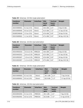
  • 9. PTP 810 Series User Guide Ordering MMUs ................................................................................................................ 2-39  Ordering capacity upgrades and XPIC capability ............................................................. 2-40  Ordering antennas ............................................................................................................ 2-44  Ordering ODUs ................................................................................................................. 2-54  Ordering IF cable, grounding and LPUs ........................................................................... 2-65  Ordering RMKs and waveguides ....................................................................................... 2-70  Ordering coupler mounting kits ........................................................................................ 2-73  Ordering OMKs ................................................................................................................. 2-75  Ordering network connection components ....................................................................... 2-75  Chapter 3:  Legal information ..................................................................................... 3-1  Cambium Networks end user license agreement ..................................................................... 3-2  Acceptance of this agreement ............................................................................................. 3-2  Definitions ........................................................................................................................... 3-2  Grant of license ................................................................................................................... 3-2  Conditions of use ................................................................................................................. 3-3  Title and restrictions ........................................................................................................... 3-4  Confidentiality ..................................................................................................................... 3-4  Right to use Cambium’s name ............................................................................................ 3-5  Transfer ............................................................................................................................... 3-5  Updates ............................................................................................................................... 3-5  Maintenance........................................................................................................................ 3-5  Disclaimer ........................................................................................................................... 3-6  Limitation of liability ........................................................................................................... 3-6  U.S. government ................................................................................................................. 3-7  Term of license .................................................................................................................... 3-7  Governing law ..................................................................................................................... 3-7  Assignment .......................................................................................................................... 3-8  Survival of provisions .......................................................................................................... 3-8  Entire agreement ................................................................................................................ 3-8  Third party software ........................................................................................................... 3-8  Limit of liability ......................................................................................................................... 3-9  Chapter 4:  Reference information .............................................................................. 4-1  Equipment specifications .......................................................................................................... 4-2  MMU specifications ............................................................................................................ 4-2  ODU specifications .............................................................................................................. 4-5  Flexible waveguide specifications ....................................................................................... 4-9  Coupler mounting kit specifications ................................................................................. 4-14  phn-2779_001v000 (Jul 2012) v
  • 10. Contents MMU front panel connectors ............................................................................................ 4-16  Wireless specifications ............................................................................................................ 4-23  General wireless specifications......................................................................................... 4-23  Frequency bands and channel separation ........................................................................ 4-24  Capacity license keys and frequency bands...................................................................... 4-25  Maximum E1/T1 circuit capacity ...................................................................................... 4-27  Capacity, transmit power and sensitivity .......................................................................... 4-29  Data network specifications .................................................................................................... 4-73  Fast Ethernet specifications ............................................................................................. 4-73  Gigabit Ethernet specifications ......................................................................................... 4-75  Network management specifications ...................................................................................... 4-77  Standard SNMP MIBs ....................................................................................................... 4-77  Electromagnetic compliance ................................................................................................... 4-79  Compliance testing ........................................................................................................... 4-79  Electrical safety compliance ............................................................................................. 4-79  European Union compliance ............................................................................................. 4-80  Canada compliance ........................................................................................................... 4-80  United States compliance ................................................................................................. 4-81  Notifications ...................................................................................................................... 4-82  Radiation hazard assessment .................................................................................................. 4-83  ETSI method ..................................................................................................................... 4-83  FCC method ...................................................................................................................... 4-85  Chapter 5:  Installation .............................................................................................. 5-1  Preparing for installation .......................................................................................................... 5-2  Safety precautions during installation ................................................................................ 5-2  Grounding and lightning protection requirements ............................................................. 5-2  Selecting installation options .............................................................................................. 5-2  Preparing personnel............................................................................................................ 5-3  Preparing inventory ............................................................................................................ 5-3  Preparing tools .................................................................................................................... 5-3  Installing antennas and ODUs .................................................................................................. 5-5  Installing a direct mount antenna with one ODU ............................................................... 5-6  Installing a remote mount antenna with one ODU ........................................................... 5-10  Installing a direct mount antenna with two ODUs (via coupler) ...................................... 5-21  Installing a remote mount antenna with two ODUs (via coupler) .................................... 5-28  Installing a direct mount dual-polar antenna with two ODUs .......................................... 5-34  Installing the IF and ground cables ........................................................................................ 5-38  vi phn-2779_001v000 (Jul 2012)
  • 11. PTP 810 Series User Guide Preparing IF cables ........................................................................................................... 5-40  Fitting an N type or straight TNC connector .................................................................... 5-40  Fitting a right angle TNC connector ................................................................................. 5-44  Connecting the ODU to the top LPU ................................................................................. 5-44  Weatherproofing an N type connector .............................................................................. 5-47  Hoisting the main IF cable ................................................................................................ 5-52  Installing and grounding the main IF cable ...................................................................... 5-55  Making an IF cable ground point ...................................................................................... 5-57  Installing and grounding the IF cable at building entry ................................................... 5-61  Testing the ODU and IF cable ................................................................................................. 5-63  Recommended pre-power tests ......................................................................................... 5-63  Test equipment ................................................................................................................. 5-63  Test preparation ................................................................................................................ 5-64  Testing cable loss .............................................................................................................. 5-65  Measuring distance to fault .............................................................................................. 5-68  Installing the MMU ................................................................................................................. 5-71  Mounting the MMU ........................................................................................................... 5-71  Grounding the MMU ......................................................................................................... 5-72  Connecting the MMU to the IF cable................................................................................ 5-73  Connecting the MMU power supply ................................................................................. 5-73  Preparing network connections (1+0 and 2+0 links) ............................................................. 5-77  Installing an Ethernet data interface ................................................................................ 5-78  Installing a fiber data interface......................................................................................... 5-79  Installing a management interface ................................................................................... 5-82  Installing an E1/T1 interface ............................................................................................. 5-83  Installing an XPIC interface .............................................................................................. 5-85  Chapter 6:  Configuration and alignment .................................................................... 6-1  Preparing for configuration and alignment .............................................................................. 6-2  Safety precautions during configuration and alignment .................................................... 6-2  Regulatory compliance during configuration and alignment .............................................. 6-2  Selecting configuration options .......................................................................................... 6-2  Purchasing license key ........................................................................................................ 6-2  Task 1: Connecting to the unit .................................................................................................. 6-3  Configuring the management PC ........................................................................................ 6-3  Updating the ARP table....................................................................................................... 6-6  Connecting to the PC and powering up .............................................................................. 6-7  Logging into the web interface ........................................................................................... 6-7  phn-2779_001v000 (Jul 2012) vii
  • 12. Contents Logging into the CLI interface ............................................................................................ 6-9  Task 2: Configuring IP and Ethernet interfaces ..................................................................... 6-14  Configuring the IP interface ............................................................................................. 6-14  Reconnecting to the management PC ............................................................................... 6-15  Configuring Serial Port ..................................................................................................... 6-15  Configuring Ethernet payload ........................................................................................... 6-16  Configuring Ethernet network management .................................................................... 6-21  Task 3: Configuring wireless interface ................................................................................... 6-24  Viewing the configuration summary ................................................................................. 6-24  Updating link configuration .............................................................................................. 6-25  Configuring the ODU ........................................................................................................ 6-33  Configuring APC and coupler loss compensation ............................................................. 6-34  Task 4: Configuring E1/T1 interfaces ..................................................................................... 6-38  Configuring channel mapping ........................................................................................... 6-38  Configuring E1/T1 ports ................................................................................................... 6-42  Configuring E1/T1 protection switching ........................................................................... 6-45  Task 5: Configuring data orderwire ........................................................................................ 6-48  Configuring orderwire ...................................................................................................... 6-48  Task 6: Configuring protection ............................................................................................... 6-50  Configuring protection ...................................................................................................... 6-50  Task 7: Setting up SNMP agent .............................................................................................. 6-54  Configuring SNMP agent .................................................................................................. 6-54  Task 8: Configuring alarms and messages ............................................................................. 6-57  Configuring generation of diagnostics alarms .................................................................. 6-57  Configuring alarm thresholds ........................................................................................... 6-59  Task 9: Configuring syslog ...................................................................................................... 6-62  Configuring system logging (syslog) ................................................................................. 6-62  Task 10: Configuring quality of service .................................................................................. 6-63  Setting QoS priority method ............................................................................................. 6-63  Setting QoS port priorities ................................................................................................ 6-66  Setting QoS VLAN p-bit tag priorities .............................................................................. 6-68  Setting QoS DiffServ DSCP priorities ............................................................................... 6-69  Setting QoS switch priorities ............................................................................................ 6-71  Task 11: Configuring VLAN .................................................................................................... 6-73  Configuring global VLAN options ..................................................................................... 6-73  Configuring static VLANs ................................................................................................. 6-75  Configuring port based VLANs ......................................................................................... 6-77  viii phn-2779_001v000 (Jul 2012)
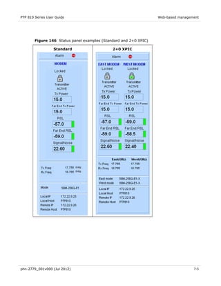
  • 13. PTP 810 Series User Guide Example VLAN configurations .......................................................................................... 6-78  Configuring MSTPs ........................................................................................................... 6-88  Mapping VLANs to MSTP instances ................................................................................. 6-91  Task 12: LACP configuration .................................................................................................. 6-92  Configuring LACP ............................................................................................................. 6-92  Task 13: Connecting link to the network ................................................................................ 6-94  Connecting to the network................................................................................................ 6-94  Setting the real-time clock ................................................................................................ 6-95  Task 14: Aligning antennas ..................................................................................................... 6-98  Introduction to antenna alignment ................................................................................... 6-98  Prerequisites for alignment .............................................................................................. 6-99  Aligning protected antennas ............................................................................................. 6-99  Aligning dual-polar antennas ............................................................................................ 6-99  Aligning a pair of antennas ............................................................................................. 6-100  Starting antenna alignment ............................................................................................ 6-100  Aligning antennas ........................................................................................................... 6-100  Completing alignment ..................................................................................................... 6-103  Task 15: Reviewing configuration and performance ............................................................ 6-104  Reviewing system configuration attributes..................................................................... 6-104  Monitoring link performance .......................................................................................... 6-105  Chapter 7:  Operation ................................................................................................. 7-1  Web-based management ........................................................................................................... 7-2  Accessing the web interface ............................................................................................... 7-2  Layout of the web interface ................................................................................................ 7-3  Viewing the system status................................................................................................... 7-4  Using the menu options ...................................................................................................... 7-9  Logging out ....................................................................................................................... 7-14  Managing alarms and events .................................................................................................. 7-15  Managing alarms .............................................................................................................. 7-15  Managing SNMP traps ...................................................................................................... 7-20  Managing event notification messages ............................................................................. 7-20  Disabling, enabling, muting and unmuting the ODU .............................................................. 7-21  Disabling the ODU ............................................................................................................ 7-21  Enabling the ODU ............................................................................................................. 7-22  Muting the ODU ................................................................................................................ 7-22  Unmuting the ODU ........................................................................................................... 7-22  Managing 1+1 Hot Standby links ........................................................................................... 7-23  phn-2779_001v000 (Jul 2012) ix
  • 14. Contents Forcing protection switches.............................................................................................. 7-23  Enabling revertive and non-revertive switching ............................................................... 7-23  Enabling and disabling fault protection ............................................................................ 7-24  Selecting preferred transmitting ODU ............................................................................. 7-24  Managing 2+0 Co-Polar, Cross-Polar & XPIC links ................................................................ 7-25  GigE Master I/O operation ................................................................................................ 7-25  Standard Master I/O operation ......................................................................................... 7-26  Link outage considerations ............................................................................................... 7-26  Managing user accounts and security .................................................................................... 7-27  Creating user accounts ..................................................................................................... 7-27  Deleting user accounts ..................................................................................................... 7-28  Changing a password ........................................................................................................ 7-29  Viewing event log of MMU access .................................................................................... 7-29  Configuring HTTP (SSL) ................................................................................................... 7-30  Managing performance ........................................................................................................... 7-31  Viewing wireless link performance ................................................................................... 7-31  Viewing Ethernet switch statistics .................................................................................... 7-42  Maintaining the system ..................................................................................................... 7-50  Saving, restoring and rebooting ............................................................................................. 7-51  Saving the system configuration ....................................................................................... 7-51  Restoring the system configuration .................................................................................. 7-52  Rebooting .......................................................................................................................... 7-53  Checking the recovery version ......................................................................................... 7-53  Restoring system defaults ....................................................................................................... 7-54  Power on reset to system defaults .................................................................................... 7-54  Restore system defaults page ........................................................................................... 7-54  System default parameter values ..................................................................................... 7-55  Viewing device information .................................................................................................... 7-57  General device information ............................................................................................... 7-57  Serial number information ................................................................................................ 7-58  Device name and owner information ................................................................................ 7-58  Upgrading the system ............................................................................................................. 7-60  Entering an authorization key........................................................................................... 7-60  Installing new software versions ...................................................................................... 7-63  Removing and installing modules ........................................................................................... 7-67  Preparing to remove and install a module ........................................................................ 7-67  Removing a module ........................................................................................................... 7-68  x phn-2779_001v000 (Jul 2012)
  • 15. PTP 810 Series User Guide Installing a module ............................................................................................................ 7-69  Installing dual modem upgrade kit ................................................................................... 7-69  Software images stored on MMU modules ....................................................................... 7-70  Chapter 8:  Troubleshooting ....................................................................................... 8-1  Trouble connecting to the web management interface ............................................................ 8-2  Check the MMU power supply status LED ......................................................................... 8-2  Check the DC supply to the MMU ...................................................................................... 8-2  Check the MMU status indicators....................................................................................... 8-3  Check the NMS port Ethernet connection .......................................................................... 8-3  Check IP network connection ............................................................................................. 8-4  Check browser settings ....................................................................................................... 8-5  Using a serial port connection to set the IP address .......................................................... 8-5  Unable to access MMU using HTTPS ................................................................................. 8-6  Unable to access MMU using Telnet .................................................................................. 8-7  Unable to access MMU using SSH ..................................................................................... 8-7  Unable to access MMU using serial port ............................................................................ 8-7  Trouble establishing a wireless link .......................................................................................... 8-8  Connect to the web management interface ........................................................................ 8-8  Check for proper link configuration and connectivity ........................................................ 8-8  Transmitter status ............................................................................................................. 8-10  Antenna alignment ............................................................................................................ 8-10  Check transmit and receive frequencies ........................................................................... 8-11  Check waveguide and antennas ........................................................................................ 8-11  Check link status ............................................................................................................... 8-11  Trouble bridging Ethernet data traffic ................................................................................... 8-12  Trouble bridging E1/T1 traffic ................................................................................................ 8-15  Check for proper configuration and connectivity ............................................................. 8-15  Performing a loopback test ............................................................................................... 8-15  BERT mode........................................................................................................................ 8-18  Trouble managing remote unit ............................................................................................... 8-20  Glossary ........................................................................................................................... I  Alarms ............................................................................................................................. V  phn-2779_001v000 (Jul 2012) xi
  • 16. PTP 810 Series User Guide List of Figures Figure 1 Typical PTP 810 deployment .......................................................................................... 1-4  Figure 2 Example of a 1+0 ring configuration .............................................................................. 1-7  Figure 3 MMU module locations ................................................................................................... 1-8  Figure 4 MMU module Power Supply Module front panel ........................................................... 1-9  Figure 5 MMU Control Module front panel ................................................................................ 1-10  Figure 6 MMU Modem Module front panel ................................................................................ 1-11  Figure 7 MMU Standard Master I/O Module front panel ........................................................... 1-13  Figure 8 MMU GigE Master I/O Module front panel .................................................................. 1-14  Figure 9 MMU additional module locations ................................................................................ 1-15  Figure 10 MMU XPIC cable linking two Modem Modules ......................................................... 1-16  Figure 11 MMU expansion I/O: 16 × E1/T1 front panel ............................................................. 1-16  Figure 12 ODU-A front view ........................................................................................................ 1-20  Figure 13 ODU-B front view ........................................................................................................ 1-20  Figure 14 ODU rear view ............................................................................................................ 1-21  Figure 15 ODU-A side view ......................................................................................................... 1-21  Figure 16 ODU-B side view ......................................................................................................... 1-22  Figure 17 Typical PTP 810 antenna with ODU (Cambium direct mount interface) .................... 1-24  Figure 18 Direct mount mechanical interface ............................................................................ 1-25  Figure 19 ODU clipped onto direct mount mechanical interface ............................................... 1-25  Figure 20 Remote mount antenna waveguide interface ............................................................. 1-25  Figure 21 RMK showing the ODU interface................................................................................ 1-26  Figure 22 RMK showing the waveguide interface ...................................................................... 1-27  Figure 23 ODU coupler mounting kit .......................................................................................... 1-28  Figure 24 Two ODUs and antenna mounted on a coupler .......................................................... 1-28  Figure 25 Orthogonal mode transducer ...................................................................................... 1-29  Figure 26 Cable grounding kit (Cambium part number 01010419001) ..................................... 1-32  Figure 27 LPU end kit (Cambium part number WB3657) ........................................................... 1-32  Figure 28 Internal Ethernet switch for the Standard Master I/O module .................................. 1-39  Figure 29 Internal Ethernet switch for the GigE Master I/O module ......................................... 1-40  Figure 30 Internal Ethernet switch for the management network ............................................. 1-48  Figure 31 Switching of E1/T1 circuits in 1+0 and 1+1 links ...................................................... 1-59  phn-2779_001v000 (Jul 2012) xii
  • 17. PTP 810 Series User Guide Figure 32 Supported loopback tests ........................................................................................... 1-62  Figure 33 LINKPlanner profile view ............................................................................................. 2-5  Figure 34 LINKPlanner configuration and performance details ................................................... 2-6  Figure 35 LINKPlanner Bill of Materials view .............................................................................. 2-6  Figure 36 Rolling sphere method to determine the lightning protection zones ........................... 2-8  Figure 37 Grounding and lightning protection on mast or tower ............................................... 2-11  Figure 38 Grounding and lightning protection on mast or tower (protected end) ..................... 2-12  Figure 39 Grounding and lightning protection on building ........................................................ 2-13  Figure 40 Grounding and lightning protection inside high building ........................................... 2-14  Figure 41 Grounding and lightning protection inside high building (protected end) ................. 2-15  Figure 42 PTP 810 MMU Ethernet QoS Priority Queue.............................................................. 2-17  Figure 43 Schematic view of 1+0 ODU direct mount link end ................................................... 2-23  Figure 44 Schematic view of 1+0 ODU remote mount link end ................................................. 2-24  Figure 45 ODUs coupled to single direct mount antenna (schematic) ....................................... 2-26  Figure 46 ODUs coupled to single remote mount antenna (schematic) ..................................... 2-27  Figure 47 ODUs with separate direct mount antennas (schematic) ........................................... 2-28  Figure 48 ODUs with separate remote mount antennas (schematic) ......................................... 2-29  Figure 49 ODUs coupled to single direct mount antenna - co-polar links (schematic) ............... 2-32  Figure 50 ODUs coupled to a single remote mount antenna - co-polar links (schematic) .......... 2-33  Figure 51 ODUs coupled to a single direct mount antenna - cross-polar links (schematic) ....... 2-34  Figure 52 ODUs connected to a dual polar remote mount antenna - cross-polar links (schematic) ................................................................................................................................................ 2-35  Figure 53 Location of chassis serial number on MMU enclosure ............................................... 2-42  Figure 54 Locations of waveguide flanges .................................................................................... 4-9  Figure 55 Waveguide flanges – 6 GHz ........................................................................................ 4-11  Figure 56 Waveguide flanges – 7 to 15 GHz ............................................................................... 4-12  Figure 57 Waveguide flanges – 18 to 38 GHz ............................................................................. 4-13  Figure 58 Waveguide flanges – 11 GHz tapered transition......................................................... 4-13  Figure 59 Molex LFH Matrix 50 Receptacle 100 Ω /120 Ω Balanced interface .......................... 4-19  Figure 60 Data order wire - RS-422 connector ............................................................................ 4-21  Figure 61 Data order wire - RS-232 connector ............................................................................ 4-21  Figure 62 XPIC connector (Modem module) ............................................................................... 4-21  Figure 63 ODU connector (Modem module) ............................................................................... 4-22  Figure 64 European Union compliance label .............................................................................. 4-82  Figure 65 Dual-polar antenna in remote mount configuration ................................................... 5-11  Figure 66 Words embossed on coupler ....................................................................................... 5-22  Figure 67 Correct orientation of LPUs ........................................................................................ 5-39  phn-2779_001v000 (Jul 2012) xiii
  • 18. List of Figures Figure 68 ODU and top LPU grounding ...................................................................................... 5-44  Figure 69 Using the hoist line ..................................................................................................... 5-54  Figure 70 IF cable grounding on a mast or tower ...................................................................... 5-55  Figure 71 Grounding at building entry ....................................................................................... 5-61  Figure 72 Example of a cable analyzer ....................................................................................... 5-64  Figure 73 Example of the cable test ........................................................................................... 5-64  Figure 74 Cable loss plot for a 14 meter cable with no ODU ..................................................... 5-66  Figure 75 Cable loss plot for a 14 meter cable with ODU connected ......................................... 5-67  Figure 76 DTF plot for a 17 meter cable with no ODU ............................................................... 5-69  Figure 77 DTF plot for a 17 meter cable with ODU connected .................................................. 5-70  Figure 78 MMU with rack mounting bracket (front mounting option shown)............................ 5-71  Figure 79 MMU ground connector ............................................................................................. 5-72  Figure 80 MMU IF cable connector (non-standard connector shown) ....................................... 5-73  Figure 81 MMU DC power cable connector ............................................................................... 5-74  Figure 82 MMU with power cable connected ............................................................................. 5-75  Figure 83 Copper data interface connections ............................................................................. 5-78  Figure 84 Fiber data interface connections ................................................................................ 5-79  Figure 85 Management interface connections............................................................................ 5-82  Figure 86 E1/T1 interface (RJ-48C) ............................................................................................. 5-83  Figure 87 E1/T1 interface (molex 60-pin) ................................................................................... 5-84  Figure 88 XPIC interface ............................................................................................................. 5-85  Figure 89 Starting Information page ............................................................................................ 6-8  Figure 90 CLI General Information page .................................................................................... 6-10  Figure 91 CLI Main Menu page .................................................................................................. 6-11  Figure 92 Example of a configurable CLI page........................................................................... 6-12  Figure 93 General Network Configuration page......................................................................... 6-14  Figure 94 Serial Configuration page ........................................................................................... 6-16  Figure 95 Ethernet Payload page for MMU Standard Master I/O module ................................. 6-17  Figure 96 Ethernet Payload page for MMU GigE Master I/O module ........................................ 6-18  Figure 97 Ethernet Payload page for MMU GigE Master I/O module with an SFP module ....... 6-19  Figure 98 Ethernet NMS page .................................................................................................... 6-22  Figure 99 Summary of Configurations page ............................................................................... 6-24  Figure 100 ODU Operational Mode page.................................................................................... 6-26  Figure 101 IDU Operational mode page ..................................................................................... 6-27  Figure 102 Payload Configuration page...................................................................................... 6-28  Figure 103 ODU Tx Power Configuration page .......................................................................... 6-29  Figure 104 ODU Channel Selection page ................................................................................... 6-31  xiv phn-2779_001v000 (Jul 2012)
  • 19. PTP 810 Series User Guide Figure 105 Adaptive Coding Modulation page ............................................................................ 6-31  Figure 106 Summary of Configurations page with Redo and Update All buttons ...................... 6-33  Figure 107 ODU Tx Mute page ................................................................................................... 6-34  Figure 108 APC Configuration page ........................................................................................... 6-35  Figure 109 E1/T1 Channel Map page (pre-defined mapping) ..................................................... 6-39  Figure 110 E1/T1 Channel Map page (custom mapping) ............................................................ 6-41  Figure 111 E1/T1 Channel Map page (custom mapping updated).............................................. 6-41  Figure 112 E1/T1 Configurations page ....................................................................................... 6-43  Figure 113 E1/T1 Protection Switching page ............................................................................. 6-45  Figure 114 Voice Orderwire Configuration ................................................................................. 6-49  Figure 115 Protection Configuration page .................................................................................. 6-50  Figure 116 Remote transmit switch algorithm ........................................................................... 6-53  Figure 117 SNMP Configuration page ........................................................................................ 6-54  Figure 118 Alarm Configuration page......................................................................................... 6-58  Figure 119 Alarm Threshold page ............................................................................................... 6-60  Figure 120 Syslog Configuration page ........................................................................................ 6-62  Figure 121 QoS Global Configuration page (Standard Master I/O module) ............................... 6-63  Figure 122 QoS Global Configuration page (GigE Master I/O module) ...................................... 6-65  Figure 123 QoS Port Priority Map page (Standard Master I/O module)..................................... 6-67  Figure 124 QoS Port Priority Map for GigE Master I/O module ................................................. 6-68  Figure 125 QoS VLAN p-bit Tag Priority Map page .................................................................... 6-69  Figure 126 QoS DiffServ DSCP Map page (Standard Master I/O module) ................................. 6-70  Figure 127 QoS DiffServ DSCP Priority Map for GigE Master I/O module................................. 6-71  Figure 128 Switch Priority to Tx Priority Queue Map (GigE Master I/O module) ...................... 6-72  Figure 129 Global VLAN Configuration page.............................................................................. 6-74  Figure 130 Static VLAN Configuration ....................................................................................... 6-76  Figure 131 Add/Edit VLAN Configuration ................................................................................... 6-76  Figure 132 Port Based Forwarding Mode page .......................................................................... 6-77  Figure 133 MSTP Configuration page (when no MSTP instances exist)..................................... 6-89  Figure 134 MSTP Configuration page (when MSTP instances exist) ........................................ 6-89  Figure 135 MSTP Instance to VLAN Map page .......................................................................... 6-91  Figure 136 LACP Configuration page ......................................................................................... 6-92  Figure 137 LACP Status page ..................................................................................................... 6-93  Figure 138 Set Data & Time page (SNTP disabled) .................................................................... 6-96  Figure 139 Set Data & Time page (SNTP enabled)..................................................................... 6-97  Figure 140 Symmetrical relationship between voltage and alignment ..................................... 6-102  Figure 141 Typical RSSI voltage peaks and troughs ................................................................ 6-102  phn-2779_001v000 (Jul 2012) xv
  • 20. List of Figures Figure 142 Summary of Configuration page ............................................................................. 6-104  Figure 143 System Administration Login page ............................................................................. 7-2  Figure 144 Web interface without status panel ............................................................................ 7-3  Figure 145 Web interface with status panel ................................................................................. 7-4  Figure 146 Status panel examples (Standard and 2+0 XPIC) ...................................................... 7-5  Figure 147 Status panel examples (Protected Non-diversity, East/East and East/West) ............. 7-6  Figure 148 Menu bar .................................................................................................................... 7-9  Figure 149 Active Alarms page ................................................................................................... 7-15  Figure 150 Alarm History page ................................................................................................... 7-18  Figure 151 ODU Configuration page .......................................................................................... 7-21  Figure 152 Add User page .......................................................................................................... 7-27  Figure 153 Delete User page ...................................................................................................... 7-28  Figure 154 Event Log page ......................................................................................................... 7-29  Figure 155 Security Configuration page ..................................................................................... 7-30  Figure 156 RSL Graph ................................................................................................................ 7-32  Figure 157 Signal Noise Ratio Graph ......................................................................................... 7-33  Figure 158 XPIC SNR Graph ....................................................................................................... 7-34  Figure 159 Tx Power Graph ........................................................................................................ 7-35  Figure 160 RF Link Performance Graph ..................................................................................... 7-36  Figure 161 Equalizer Taps Graph ............................................................................................... 7-37  Figure 162 XPIC Equalizer Taps Graph ...................................................................................... 7-38  Figure 163 Constellation Graph (256 QAM) ............................................................................... 7-39  Figure 164 XPIC Constellation Graph (256 QAM) ...................................................................... 7-40  Figure 165 Temperature Graph .................................................................................................. 7-41  Figure 166 NMS Switch Statistics page ..................................................................................... 7-42  Figure 167 Data Switch (payload port) Statistics page .............................................................. 7-44  Figure 168 Ethernet NMS – IEEE 802.1w RSTP Status page ..................................................... 7-46  Figure 169 Ethernet Payload – IEEE 802.1w RSTP page ........................................................... 7-47  Figure 170 Ethernet Payload – IEEE 802.1s MSTP page ............................................................ 7-48  Figure 171 Save/Restore Configuration page ............................................................................. 7-51  Figure 172 System Reboot page ................................................................................................. 7-53  Figure 173 Restore System Defaults page .................................................................................. 7-55  Figure 174 Device Information page........................................................................................... 7-57  Figure 175 Serial Number Information page .............................................................................. 7-58  Figure 176 Device Names page .................................................................................................. 7-59  Figure 177 Authorization Key ..................................................................................................... 7-61  Figure 178 XPIC Authorization Key ............................................................................................ 7-62  xvi phn-2779_001v000 (Jul 2012)
  • 21. PTP 810 Series User Guide Figure 179 Reprogramming page ............................................................................................... 7-64  Figure 180 MMU Modules .......................................................................................................... 7-67  Figure 181 Thumbscrew Locations ............................................................................................. 7-68  Figure 182 Threaded Hole Locations .......................................................................................... 7-68  Figure 183 Guides ....................................................................................................................... 7-69  Figure 184 Loopback page .......................................................................................................... 8-16  Figure 185 BERT Mode page ...................................................................................................... 8-19  phn-2779_001v000 (Jul 2012) xvii
  • 22. PTP 810 Series User Guide List of Tables Table 1 PTP 810 licensed bands and frequencies ......................................................................... 1-3  Table 2 ODU interfaces ............................................................................................................... 1-22  Table 3 Insertion of tags in ingress frames in double tagged mode ........................................... 1-44  Table 4 Default user accounts ..................................................................................................... 1-51  Table 5 Web-based and CLI access rights................................................................................... 1-51  Table 6 MMU software versions ................................................................................................. 1-55  Table 7 E1/T1 port capacity ........................................................................................................ 1-58  Table 8 MMU base modules ........................................................................................................ 2-39  Table 9 MMU spare, expansion and upgrade modules ............................................................... 2-39  Table 10 MMU accessories ......................................................................................................... 2-40  Table 11 Single-step capacity upgrades (per MMU) ................................................................... 2-41  Table 12 Step-by-step capacity upgrades (per MMU)................................................................. 2-41  Table 13 XPIC capability (per MMU) .......................................................................................... 2-42  Table 14 Selecting antennas for each hardware configuration .................................................. 2-44  Table 15 Antennas: 6 GHz single polarization ............................................................................ 2-45  Table 16 Antennas: 6 GHz dual polarization ............................................................................... 2-45  Table 17 Antennas: 7 GHz and 8 GHz single polarization .......................................................... 2-46  Table 18 Antennas: 7 GHz and 8 GHz dual polarization ............................................................. 2-46  Table 19 Antennas: 11 GHz single polarization .......................................................................... 2-47  Table 20 Antennas: 11 GHz dual polarization ............................................................................. 2-47  Table 21 Antennas: 13 GHz single polarization .......................................................................... 2-48  Table 22 Antennas: 13 GHz dual polarization ............................................................................. 2-48  Table 23 Antennas: 15 GHz single polarization .......................................................................... 2-49  Table 24 Antennas: 15 GHz dual polarization ............................................................................. 2-49  Table 25 Antennas: 18 GHz single polarization .......................................................................... 2-50  Table 26 Antennas: 18 GHz dual polarization ............................................................................. 2-50  Table 27 Antennas: 23 GHz single polarization .......................................................................... 2-51  Table 28 Antennas: 23 GHz dual polarization ............................................................................. 2-51  Table 29 Antennas: 26 GHz single polarization .......................................................................... 2-52  Table 30 Antennas: 26 GHz dual polarization ............................................................................. 2-52  Table 31 Antennas: 28 GHz single polarization .......................................................................... 2-52  phn-2779_001v000 (Jul 2012) xviii
  • 23. PTP 810 Series User Guide Table 32 Antennas: 28 GHz dual polarization ............................................................................. 2-52  Table 33 Antennas: 32 GHz single polarization .......................................................................... 2-53  Table 34 Antennas: 32 GHz dual polarization ............................................................................. 2-53  Table 35 Antennas: 38 GHz single polarization .......................................................................... 2-53  Table 36 Antennas: 38 GHz dual polarization ............................................................................. 2-53  Table 37 Parabolic radomes (optional)........................................................................................ 2-54  Table 38 ODUs: Lower 6 GHz ODU-A ......................................................................................... 2-55  Table 39 ODUs: Upper 6 GHz ODU-A ......................................................................................... 2-55  Table 40 ODUs: 7 GHz ODU-A .................................................................................................... 2-56  Table 41 ODUs: 8 GHz ODU-A .................................................................................................... 2-58  Table 42 ODUs: 11 GHz ODU-B .................................................................................................. 2-59  Table 43 ODUs: 11 GHz ODU-A .................................................................................................. 2-59  Table 44 ODUs: 13 GHz ODU-A .................................................................................................. 2-60  Table 45 ODUs: 15 GHz ODU-A .................................................................................................. 2-60  Table 46 ODUs: 18 GHz ODU-B .................................................................................................. 2-61  Table 47 ODUs: 18 GHz ODU-A .................................................................................................. 2-62  Table 48 ODUs: 23 GHz ODU-B .................................................................................................. 2-62  Table 49 ODUs: 23 GHz ODU-A .................................................................................................. 2-62  Table 50 ODUs: 26 GHz ODU-A .................................................................................................. 2-63  Table 51 ODUs: 28 GHz ODU-A .................................................................................................. 2-64  Table 52 ODUs: 32 GHz ODU-A .................................................................................................. 2-64  Table 53 ODUs: 38 GHz ODU-A .................................................................................................. 2-64  Table 54 Cable and LPU components.......................................................................................... 2-65  Table 55 Inventory of the coaxial cable installation assembly kit (WB3616) .............................. 2-68  Table 56 RMKs, waveguides and accessories ............................................................................. 2-70  Table 57 Remote mounting kits................................................................................................... 2-71  Table 58 Flexible waveguides ..................................................................................................... 2-71  Table 59 Flex-twist hanger kits available from Cambium ........................................................... 2-73  Table 60 ODU coupler mounting kits .......................................................................................... 2-73  Table 61 Orthogonal mounting kits (OMKs)................................................................................ 2-75  Table 62 Copper network cables and connectors ....................................................................... 2-75  Table 63 Fiber network cables and connectors .......................................................................... 2-76  Table 64 MMU physical specifications .......................................................................................... 4-2  Table 65 MMU environmental specifications ................................................................................ 4-2  Table 66 MMU electrical specifications ........................................................................................ 4-2  Table 67 Worst case power consumption for 1+0 link types ........................................................ 4-3  Table 68 Worst case power consumption for 1+1 link types (*1) ................................................. 4-3  phn-2779_001v000 (Jul 2012) xix
  • 24. List of Tables Table 69 Worst case power consumption for 2+0 link types (*1) ................................................. 4-4  Table 70 AC to DC converter specifications .................................................................................. 4-4  Table 71 ODU physical specifications ........................................................................................... 4-5  Table 72 ODU-A and ODU-B environmental specifications........................................................... 4-5  Table 73 RSSI voltage, received signal level and bandwidth........................................................ 4-6  Table 74 Antenna, transition, waveguide and RMK flanges ....................................................... 4-10  Table 75 Torque value in Nm (lb ft) for each fastener size ......................................................... 4-14  Table 76 ODU coupler physical specifications ............................................................................ 4-14  Table 77 ODU coupler environmental specifications .................................................................. 4-14  Table 78 ODU coupler return losses and isolation ...................................................................... 4-15  Table 79 ODU coupler insertion losses ....................................................................................... 4-15  Table 80 DC Input (power) connector (Power Supply module) .................................................... 4-16  Table 81 Ethernet 100Base-T payload connector 1-2 (Master I/O module) ................................. 4-16  Table 82 Ethernet 1000Base-T payload connector 1-4 (GigE Master I/O module) ...................... 4-17  Table 83 Gigabit Ethernet optical SFP connector (GigE Master I/O module) ............................ 4-17  Table 84 NMS 10/100Base-TX connector 1-2 (Control module) ................................................... 4-17  Table 85 Serial/Alarm port connector (Control module) ............................................................... 4-18  Table 86 E1/T1 - channels 1-2 connector (Master I/O module).................................................... 4-18  Table 87 E1/T1 - channels 3-16 connector (Master I/O module) .................................................. 4-19  Table 88 General wireless specifications .................................................................................... 4-23  Table 89 ETSI band plan ............................................................................................................. 4-24  Table 90 FCC and IC band plan .................................................................................................. 4-25  Table 91 Cross-Reference of capacity license keys to frequency band....................................... 4-26  Table 92 Maximum number of E1/T1 circuits with ETSI channel separations ........................... 4-27  Table 93 Maximum number of E1/T1 circuits with FCC and Canada bandwidths ..................... 4-28  Table 94 Lower 6 GHz FCC and Canada with 10 MHz bandwidth ............................................. 4-30  Table 95 Lower 6 GHz FCC and Canada with 30 MHz bandwidth ............................................. 4-30  Table 96 Lower 6 GHz FCC and Canada with 30 MHz bandwidth (XPIC) .................................. 4-30  Table 97 Lower 6 GHz ETSI with 29.65 MHz channel separation .............................................. 4-31  Table 98 Lower 6 GHz ETSI with 29.65 MHz channel separation (XPIC) .................................. 4-31  Table 99 Upper 6 GHz FCC with 10 MHz bandwidth ................................................................. 4-31  Table 100 Upper 6 GHz FCC with 30 MHz bandwidth ............................................................... 4-32  Table 101 Upper 6 GHz FCC with 30 MHz bandwidth (XPIC) .................................................... 4-32  Table 102 Upper 6 GHz ETSI with 7 MHz channel separation ................................................... 4-32  Table 103 Upper 6 GHz ETSI with 14 MHz channel separation ................................................. 4-33  Table 104 Upper 6 GHz ETSI with 30 MHz channel separation ................................................. 4-33  Table 105 Upper 6 GHz ETSI with 30 MHz channel separation (XPIC) ..................................... 4-33  xx phn-2779_001v000 (Jul 2012)
  • 25. PTP 810 Series User Guide Table 106 Upper 6 GHz ETSI with 40 MHz channel separation ................................................. 4-34  Table 107 Upper 6 GHz ETSI with 40 MHz channel separation (XPIC)...................................... 4-34  Table 108 Upper 6 GHz ETSI with 60 MHz channel separation ................................................. 4-34  Table 109 Upper 6 GHz ETSI with 60 MHz channel separation (XPIC)...................................... 4-35  Table 110 7 GHz ETSI with 7 MHz channel separation .............................................................. 4-35  Table 111 7 GHz ETSI with 14 MHz channel separation ............................................................ 4-35  Table 112 7 GHz ETSI with 28 MHz channel separation ............................................................ 4-36  Table 113 7 GHz ETSI with 28 MHz channel separation (XPIC)................................................. 4-36  Table 114 8 GHz ETSI with 7 MHz channel separation .............................................................. 4-36  Table 115 8 GHz ETSI with 14 MHz channel separation ............................................................ 4-37  Table 116 8 GHz ETSI with 28 MHz channel separation ............................................................ 4-37  Table 117 8 GHz ETSI with 28 MHz channel separation (XPIC)................................................. 4-37  Table 118 8 GHz ETSI with 29.65 MHz channel separation ....................................................... 4-38  Table 119 8 GHz ETSI with 29.65 MHz channel separation (XPIC)............................................ 4-38  Table 120 11 GHz FCC and Canada with 10 MHz bandwidth (ODU-A) ...................................... 4-38  Table 121 11 GHz FCC and Canada with 10 MHz bandwidth (ODU-B) ...................................... 4-39  Table 122 11 GHz FCC and Canada with 30 MHz bandwidth (ODU-A) ...................................... 4-39  Table 123 11 GHz FCC and Canada with 30 MHz bandwidth (ODU-B) ...................................... 4-39  Table 124 11 GHz FCC and Canada with 30 MHz bandwidth (XPIC) (ODU-A) .......................... 4-40  Table 125 11 GHz FCC and Canada with 30 MHz bandwidth (XPIC) (ODU-B) .......................... 4-40  Table 126 11 GHz FCC and Canada with 40 MHz bandwidth (ODU-A) ...................................... 4-40  Table 127 11 GHz FCC and Canada with 40 MHz bandwidth (ODU-B) ...................................... 4-41  Table 128 11 GHz FCC and Canada with 40 MHz bandwidth (XPIC) (ODU-A) .......................... 4-41  Table 129 11 GHz FCC and Canada with 40 MHz bandwidth (XPIC) (ODU-B) .......................... 4-41  Table 130 11 GHz ETSI with 40 MHz channel separation .......................................................... 4-42  Table 131 11 GHz ETSI with 40 MHz channel separation (XPIC)............................................... 4-42  Table 132 13 GHz ETSI with 7 MHz channel separation ............................................................ 4-42  Table 133 13 GHz ETSI with 14 MHz channel separation .......................................................... 4-43  Table 134 13 GHz ETSI with 28 MHz channel separation .......................................................... 4-43  Table 135 13 GHz ETSI with 28 MHz channel separation (XPIC)............................................... 4-43  Table 136 15 GHz ETSI with 7 MHz channel separation ............................................................ 4-44  Table 137 15 GHz ETSI with 14 MHz channel separation .......................................................... 4-44  Table 138 15 GHz ETSI with 28 MHz channel separation .......................................................... 4-44  Table 139 15 GHz ETSI with 28 MHz channel separation (XPIC)............................................... 4-45  Table 140 15 GHz ETSI with 56 MHz channel separation .......................................................... 4-45  Table 141 15 GHz ETSI with 56 MHz channel separation (XPIC)............................................... 4-45  Table 142 18 GHz FCC and Canada with 10 MHz bandwidth (ODU-A) ...................................... 4-46  phn-2779_001v000 (Jul 2012) xxi
  • 26. List of Tables Table 143 18 GHz FCC and Canada with 10 MHz bandwidth (ODU-B) ...................................... 4-46  Table 144 18 GHz FCC and Canada with 20 MHz bandwidth (ODU-A) ...................................... 4-46  Table 145 18 GHz FCC and Canada with 20 MHz bandwidth (ODU-B) ...................................... 4-47  Table 146 18 GHz FCC and Canada with 30 MHz bandwidth (ODU-A) ...................................... 4-47  Table 147 18 GHz FCC and Canada with 30 MHz bandwidth (ODU-B) ...................................... 4-47  Table 148 18 GHz FCC and Canada with 30 MHz bandwidth (XPIC) (ODU-A) .......................... 4-48  Table 149 18 GHz FCC and Canada with 30 MHz bandwidth (XPIC) (ODU-B) .......................... 4-48  Table 150 18 GHz FCC and Canada with 40 MHz bandwidth (ODU-A) ...................................... 4-48  Table 151 18 GHz FCC and Canada with 40 MHz bandwidth (ODU-B) ...................................... 4-49  Table 152 18 GHz FCC and Canada with 40 MHz bandwidth (XPIC) (ODU-A) .......................... 4-49  Table 153 18 GHz FCC and Canada with 40 MHz bandwidth (XPIC) (ODU-B) .......................... 4-49  Table 154 18 GHz FCC and Canada with 50 MHz bandwidth (ODU-A) ...................................... 4-50  Table 155 18 GHz FCC and Canada with 50 MHz bandwidth (ODU-B) ...................................... 4-50  Table 156 18 GHz FCC and Canada with 50 MHz bandwidth (XPIC) (ODU-A) .......................... 4-50  Table 157 18 GHz FCC and Canada with 50 MHz bandwidth (XPIC) (ODU-B) .......................... 4-51  Table 158 18 GHz FCC and Canada with 80 MHz bandwidth (ODU-B) ...................................... 4-51  Table 159 18 GHz FCC and Canada with 80 MHz bandwidth (XPIC) (ODU-B) .......................... 4-51  Table 160 18 GHz ETSI with 7 MHz channel separation ............................................................ 4-52  Table 161 18 GHz ETSI with 13.75 MHz channel separation ..................................................... 4-52  Table 162 18 GHz ETSI with 27.5 MHz channel separation ....................................................... 4-52  Table 163 18 GHz ETSI with 55 MHz channel separation .......................................................... 4-53  Table 164 23 GHz FCC and Canada with 10 MHz bandwidth (ODU-A) ...................................... 4-53  Table 165 23 GHz FCC and Canada with 10 MHz bandwidth (ODU-B) ...................................... 4-54  Table 166 23 GHz FCC and Canada with 20 MHz bandwidth (ODU-A) ...................................... 4-54  Table 167 23 GHz FCC and Canada with 20 MHz bandwidth (ODU-B) ...................................... 4-54  Table 168 23 GHz FCC and Canada with 30 MHz bandwidth (ODU-A) ...................................... 4-55  Table 169 23 GHz FCC and Canada with 30 MHz bandwidth (ODU-B) ...................................... 4-55  Table 170 23 GHz FCC and Canada with 30 MHz bandwidth (XPIC) (ODU-A) .......................... 4-55  Table 171 23 GHz FCC and Canada with 30 MHz bandwidth (XPIC) (ODU-B) .......................... 4-56  Table 172 23 GHz FCC and Canada with 40 MHz bandwidth (ODU-A) ...................................... 4-56  Table 173 23 GHz FCC and Canada with 40 MHz bandwidth (ODU-B) ...................................... 4-56  Table 174 23 GHz FCC and Canada with 40 MHz bandwidth (XPIC) (ODU-A) .......................... 4-57  Table 175 23 GHz FCC and Canada with 40 MHz bandwidth (XPIC) (ODU-B) .......................... 4-57  Table 176 23 GHz FCC and Canada with 50 MHz bandwidth (ODU-A) ...................................... 4-57  Table 177 23 GHz FCC and Canada with 50 MHz bandwidth (ODU-B) ...................................... 4-58  Table 178 23 GHz FCC and Canada with 50 MHz bandwidth (XPIC) (ODU-A) .......................... 4-58  Table 179 23 GHz FCC and Canada with 50 MHz bandwidth (XPIC) (ODU-B) .......................... 4-58  xxii phn-2779_001v000 (Jul 2012)
  • 27. PTP 810 Series User Guide Table 180 23 GHz ETSI with 7 MHz channel separation ............................................................ 4-59  Table 181 23 GHz ETSI with 14 MHz channel separation .......................................................... 4-59  Table 182 23 GHz ETSI with 28 MHz channel separation .......................................................... 4-59  Table 183 23 GHz ETSI with 28 MHz channel separation (XPIC)............................................... 4-60  Table 184 23 GHz ETSI with 56 MHz channel separation .......................................................... 4-60  Table 185 23 GHz ETSI with 56 MHz channel separation (XPIC)............................................... 4-60  Table 186 26 GHz FCC with 10 MHz bandwidth ........................................................................ 4-61  Table 187 26 GHz FCC with 20 MHz bandwidth ........................................................................ 4-61  Table 188 26 GHz FCC with 40 MHz bandwidth ........................................................................ 4-62  Table 189 26 GHz FCC with 40 MHz bandwidth (XPIC) ............................................................. 4-62  Table 190 26 GHz ETSI with 7 MHz channel separation ............................................................ 4-62  Table 191 26 GHz ETSI with 14 MHz channel separation .......................................................... 4-63  Table 192 26 GHz ETSI with 28 MHz channel separation .......................................................... 4-63  Table 193 26 GHz ETSI with 28 MHz channel separation (XPIC)............................................... 4-63  Table 194 26 GHz ETSI with 56 MHz channel separation .......................................................... 4-64  Table 195 26 GHz ETSI with 56 MHz channel separation (XPIC)............................................... 4-64  Table 196 28 GHz ETSI with 7 MHz bandwidth.......................................................................... 4-65  Table 197 28 GHz ETSI with 14 MHz channel separation .......................................................... 4-65  Table 198 28 GHz ETSI with 28 MHz channel separation .......................................................... 4-65  Table 199 28 GHz ETSI with 28 MHz channel separation (XPIC)............................................... 4-66  Table 200 28 GHz ETSI with 56 MHz channel separation .......................................................... 4-66  Table 201 28 GHz ETSI with 56 MHz channel separation (XPIC)............................................... 4-66  Table 202 32 GHz ETSI with 7 MHz channel separation ............................................................ 4-67  Table 203 28 GHz ETSI with 14 MHz channel separation .......................................................... 4-67  Table 204 32 GHz ETSI with 28 MHz channel separation .......................................................... 4-67  Table 205 32 GHz ETSI with 28 MHz channel separation (XPIC)............................................... 4-68  Table 206 32 GHz ETSI with 56 MHz channel separation .......................................................... 4-68  Table 207 32 GHz ETSI with 56 MHz channel separation (XPIC)............................................... 4-68  Table 208 38 GHz FCC and Canada with 10 MHz bandwidth .................................................... 4-69  Table 209 38 GHz FCC and Canada with 50 MHz bandwidth .................................................... 4-69  Table 210 38 GHz FCC and Canada with 50 MHz bandwidth (XPIC) ......................................... 4-70  Table 211 38 GHz ETSI with 7 MHz channel separation ............................................................ 4-70  Table 212 38 GHz ETSI with 14 MHz channel separation .......................................................... 4-70  Table 213 38 GHz ETSI with 28 MHz channel separation .......................................................... 4-71  Table 214 38 GHz ETSI with 28 MHz channel separation (XPIC)............................................... 4-71  Table 215 38 GHz ETSI with 56 MHz channel separation .......................................................... 4-71  Table 216 38 GHz ETSI with 56 MHz channel separation (XPIC)............................................... 4-72  phn-2779_001v000 (Jul 2012) xxiii
  • 28. List of Tables Table 217 Fast Ethernet specifications ........................................................................................ 4-73  Table 218 Gigabit Ethernet specifications ................................................................................... 4-75  Table 219 Electrical safety specifications .................................................................................... 4-79  Table 220 PTP 810 minimum separation distances, ETSI method.............................................. 4-84  Table 221 PTP 810 minimum separation distances, FCC method (ODU) ................................... 4-86  Table 222 Tools required for PTP 810 installation ........................................................................ 5-3  Table 223 Selecting antenna and ODU installation procedures ................................................... 5-5  Table 224 Expected cable loss when ODU is not connected ....................................................... 5-67  Table 225 Default usernames and passwords ............................................................................... 6-8  Table 226 General Network Configuration attributes ................................................................ 6-15  Table 227 Ethernet Payload attributes (Spanning Tree Configuration) ..................................... 6-20  Table 228 Ethernet Payload attributes (Ethernet Port Configuration) ....................................... 6-20  Table 229 Ethernet NMS attributes (Spanning Tree Configuration) .......................................... 6-23  Table 230 Ethernet NMS attributes (Ethernet Port Configuration) ........................................... 6-23  Table 231 Step 1: Link Configuration mapping to ODU Operational Modes .............................. 6-26  Table 232 ODU Tx Power Configuration attributes .................................................................... 6-30  Table 233 APC attributes ............................................................................................................ 6-35  Table 234 Coupler loss attributes ............................................................................................... 6-37  Table 235 General purpose mappings ......................................................................................... 6-39  Table 236 Naming convention used in channel maps ................................................................. 6-40  Table 237 E1/T1 Configurations attributes ................................................................................. 6-44  Table 238 E1/T1 Protection Switching attributes ....................................................................... 6-46  Table 239 Protection Configuration attributes ........................................................................... 6-51  Table 240 SNMP Configuration attributes .................................................................................. 6-55  Table 241 Alarm Configuration attributes .................................................................................. 6-59  Table 242 Alarm Threshold attributes ........................................................................................ 6-61  Table 243 Syslog Configuration attributes ................................................................................. 6-62  Table 244 QoS Global Configuration attributes (Standard Master I/O module) ......................... 6-64  Table 245 QoS Global Configuration attributes (GigE Master I/O module) ................................ 6-66  Table 246 Global VLAN Configuration attributes ....................................................................... 6-74  Table 247 Add/Edit VLAN Configuration attributes .................................................................... 6-77  Table 248 MSTP Configuration attributes .................................................................................. 6-90  Table 249 LACP Configuration attributes ................................................................................... 6-93  Table 250 Manual clock attributes .............................................................................................. 6-96  Table 251 SNTP clock attributes................................................................................................. 6-97  Table 252 Status panel modem and alarm status indicators ........................................................ 7-7  Table 253 Procedures performed from each menu option .......................................................... 7-10  xxiv phn-2779_001v000 (Jul 2012)
  • 29. PTP 810 Series User Guide Table 254 Modem card status LED ............................................................................................. 7-17  Table 255 ODU Alarms ................................................................................................................ 7-18  Table 256 XPIC Alarms ................................................................................................................ 7-19  Table 257 Add User attributes .................................................................................................... 7-27  Table 258 Security Configuration attributes ............................................................................... 7-30  Table 259 NMS Switch Statistics attributes ............................................................................... 7-43  Table 260 Data Switch (payload port) attributes ........................................................................ 7-45  Table 261 Ethernet NMS – IEEE 802.1w RSTP Status attributes ............................................... 7-46  Table 262 Ethernet Payload attributes ....................................................................................... 7-49  Table 263 MMU system default parameters ................................................................................ 7-55  Table 264 Device Information attributes .................................................................................... 7-57  Table 265 Device Names attributes ............................................................................................ 7-59  Table 266 Authorization Key attributes ...................................................................................... 7-61  Table 267 MMU software images and module storage ............................................................... 7-70  Table 268 MMU power supply status LED checks ........................................................................ 8-2  Table 269 DC supply checks when MMU power supply status LED is off or red ......................... 8-2  Table 270 MMU status indicator checks ....................................................................................... 8-3  Table 271 NMS port indicator checks ........................................................................................... 8-3  Table 272 Ping response checks ................................................................................................... 8-5  Table 273 Link configuration problems ........................................................................................ 8-8  Table 274 Loopback attributes .................................................................................................... 8-17  Table 275 BERT Mode attributes ................................................................................................ 8-19  phn-2779_001v000 (Jul 2012) xxv
  • 30. List of Tables xxvi phn-2779_001v000 (Jul 2012)
  • 31. PTP 810 Series User Guide About This User Guide This guide describes the planning, installation and operation of the Cambium PTP 810. It is intended for use by the system designer, system installer and the system administrator. Users of this guide should have knowledge of the following areas: • Radio network design • Outdoor radio equipment installation • System installation, configuration, monitoring and fault finding System designers should refer to the following chapters: • Chapter 1: Product description • Chapter 2: Planning considerations • Chapter 3: Legal information • Chapter 4: Reference information Installers should refer to the following chapters: • Chapter 5: Installation • Chapter 6: Configuration and alignment • Chapter 8: Troubleshooting Operators should refer to the following chapters: • Chapter 1: Product description • Chapter 6: Configuration and alignment • Chapter 7: Operation • Chapter 8: Troubleshooting phn-2779_001v000 (Jul 2012) 1
  • 32. General information About This User Guide General information Version information The following shows the issue status of this document: Document Date of Remarks issue issue 001v000 Jul 2012 System Release 810-01-00 Contacting Cambium Networks   Support website: http://www.cambiumnetworks.com/support Main website: http://www.cambiumnetworks.com Sales enquiries: solutions@cambiumnetworks.com Support enquiries: support@cambiumnetworks.com Telephone number list: http://www.cambiumnetworks.com/contact.php Address: Cambium Networks Limited, Linhay Business Park, Eastern Road, Ashburton, Devon, UK, TQ13 7UP 2 phn-2779_001v000 (Jul 2012)
  • 33. PTP 810 Series User Guide General information Purpose Cambium Networks Point-To-Point (PTP) documents are intended to instruct and assist personnel in the operation, installation and maintenance of the Cambium PTP equipment and ancillary devices. It is recommended that all personnel engaged in such activities be properly trained. Cambium disclaims all liability whatsoever, implied or express, for any risk of damage, loss or reduction in system performance arising directly or indirectly out of the failure of the customer, or anyone acting on the customer's behalf, to abide by the instructions, system parameters, or recommendations made in this document. Cross references References to external publications are shown in italics. Other cross references, emphasized in blue text in electronic versions, are active links to the references. This document is divided into numbered chapters that are divided into sections. Sections are not numbered, but are individually named at the top of each page, and are listed in the table of contents. Feedback We appreciate feedback from the users of our documents. This includes feedback on the structure, content, accuracy, or completeness of our documents. Send feedback to support@cambiumnetworks.com. phn-2779_001v000 (Jul 2012) 3
  • 34. Problems and warranty About This User Guide Problems and warranty Reporting problems If any problems are encountered when installing or operating this equipment, follow this procedure to investigate and report: 1 Search this document and the software release notes of supported releases. 2 Visit the support website. 3 Ask for assistance from the Cambium product supplier. 4 Gather information from affected units, such as any available diagnostic downloads. 5 Escalate the problem by emailing or telephoning support. Repair and service If unit failure is suspected, obtain details of the Return Material Authorization (RMA) process from the support website. Warranty Cambium’s standard hardware warranty is for one (1) year from date of shipment from Cambium or a Cambium distributor. Cambium warrants that hardware will conform to the relevant published specifications and will be free from material defects in material and workmanship under normal use and service. Cambium shall within this time, at its own option, either repair or replace the defective product within thirty (30) days of receipt of the defective product. Repaired or replaced product will be subject to the original warranty period but not less than thirty (30) days. To register PTP products or activate warranties, visit the support website. For warranty assistance, contact the reseller or distributor. Using non-Cambium parts for repair could damage the equipment or void warranty. Contact Cambium for service and repair instructions. 4 phn-2779_001v000 (Jul 2012)
  • 35. PTP 810 Series User Guide Problems and warranty Portions of Cambium equipment may be damaged from exposure to electrostatic discharge. Use precautions to prevent damage. phn-2779_001v000 (Jul 2012) 5
  • 36. Security advice About This User Guide Security advice Cambium Networks systems and equipment provide security parameters that can be configured by the operator based on their particular operating environment. Cambium recommends setting and using these parameters following industry recognized security practices. Security aspects to be considered are protecting the confidentiality, integrity, and availability of information and assets. Assets include the ability to communicate, information about the nature of the communications, and information about the parties involved. In certain instances Cambium makes specific recommendations regarding security practices, however the implementation of these recommendations and final responsibility for the security of the system lies with the operator of the system. 6 phn-2779_001v000 (Jul 2012)
  • 37. PTP 810 Series User Guide Warnings, cautions, and notes Warnings, cautions, and notes The following describes how warnings and cautions are used in this document and in all documents of the Cambium Networks document set. Warnings Warnings precede instructions that contain potentially hazardous situations. Warnings are used to alert the reader to possible hazards that could cause loss of life or physical injury. A warning has the following format: Warning text and consequence for not following the instructions in the warning. Cautions Cautions precede instructions and are used when there is a possibility of damage to systems, software, or individual items of equipment within a system. However, this damage presents no danger to personnel. A caution has the following format: Caution text and consequence for not following the instructions in the caution. Notes A note means that there is a possibility of an undesirable situation or provides additional information to help the reader understand a topic or concept. A note has the following format: Note text. phn-2779_001v000 (Jul 2012) 7
  • 38. Caring for the environment About This User Guide Caring for the environment The following information describes national or regional requirements for the disposal of Cambium Networks supplied equipment and for the approved disposal of surplus packaging. In EU countries The following information is provided to enable regulatory compliance with the European Union (EU) directives identified and any amendments made to these directives when using Cambium equipment in EU countries. Disposal of Cambium equipment European Union (EU) Directive 2002/96/EC Waste Electrical and Electronic Equipment (WEEE) Do not dispose of Cambium equipment in landfill sites. In the EU, Cambium in conjunction with a recycling partner ensures that equipment is collected and recycled according to the requirements of EU environmental law. Disposal of surplus packaging Do not dispose of surplus packaging in landfill sites. In the EU, it is the individual recipient’s responsibility to ensure that packaging materials are collected and recycled according to the requirements of EU environmental law. In non-EU countries In non-EU countries, dispose of Cambium equipment and all surplus packaging in accordance with national and regional regulations. 8 phn-2779_001v000 (Jul 2012)
  • 39. PTP 810 Series User Guide Licensing requirements Licensing requirements Operating license This equipment operates in bands that require a license in most countries. In most countries it is illegal to operate the PTP 810 without a license from the regional or local regulating authority. United States of America This device has been verified by Cambium Networks as being in compliance with the requirements of the rules of the Federal Communications Commission (FCC), 47 C.F.R. Part 101, and may not be operated without a station license. In the United States such licenses are issued by the FCC to entities other than agencies of the United States government. Federal government agencies are licensed by the National Telecommunications and Information Administration (NTIA) acting upon the recommendation of the Interdepartment Radio Advisory Committee (IRAC). Cambium license agreement The PTP 810 must be operated in accordance with the Cambium Networks end user license agreement, as specified in Chapter 3: Legal information. phn-2779_001v000 (Jul 2012) 9
  • 40. Licensing requirements About This User Guide 10 phn-2779_001v000 (Jul 2012)
  • 41. PTP 810 Series User Guide Chapter 1: Product description This chapter provides a high level description of the PTP 810 product. It describes in general terms the function of the product, the main product variants and typical deployment. It also describes the main hardware components. The following topics are described in this chapter: • Overview on page 1-2 introduces the key features, typical uses, product variants and components of the PTP 810. • Modular modem unit (MMU) on page 1-8 describes the MMU and its interfaces. • Outdoor unit (ODU) on page 1-18 describes the ODU and its interfaces. • Antennas and couplers on page 1-24 describes the PTP 810 antennas, couplers and remote mounting kit. • Cabling and lightning protection on page 1-31 describes the cabling and lightning protection components of a PTP 810 installation. • Wireless operation on page 1-34 describes how the PTP 810 wireless link is operated, including modulation modes, power control and security. • Ethernet bridging in the customer network on page 1-38 describes how the PTP 810 bridges Ethernet data in the customer data network. • Ethernet bridging in the management network on page 1-47 describes how the PTP 810 bridges Ethernet data in the management network. • System management on page 1-50 introduces the PTP 810 management system, including the web interface, installation, configuration, alerts and upgrades. • TDM bridging on page 1-57 describes PTP 810 capabilities for E1/T1 transmission over wireless links, and for switching of E1/T1 circuits within the MMU. phn-2779_001v000 (Jul 2012) 1-1
  • 42. Overview Chapter 1: Product description Overview Cambium Networks carrier-grade PTP 810 systems provide reliable, high-capacity connectivity and backhaul for Ethernet and TDM applications. The PTP 810 provides great flexibility to configure PTP systems to address a wide range of applications at affordable cost. The PTP 810 supports a number of configurations including: 1+1 hot standby, 1+1 hot standby with spatial diversity, dual 1+0, 2+0 co-polar, 2+0 cross-polar, and 2+0 XPIC. Key features The key features of the PTP 810 are as follows: • Flexible indoor Modular Modem Unit (MMU) with pluggable modules that support T1/E1, and Ethernet interfaces. • Split mount architecture, with the Outdoor Unit (ODU) mounted outdoors and the Modular Modem Unit (MMU) mounted indoors. • Outdoor Units (ODUs) that are common to PTP 800 and PTP 810. • Native Ethernet and TDM transmission. • Built-in T1/E1 cross-connection switch. • Built-in L2 Ethernet switch. • 1+0, 1+1 Hot Standby, 1+1 Hot Standby with Spatial Diversity, 2+0 Co-Polar, 2+0 Cross Polar, 2+0 XPIC • Support for ribbon and ring networks. • Embedded link aggregation for 2+0 links. • Configurable channel bandwidths from 7 MHz to 80 MHz. • Fixed modulation modes QPSK to 256 QAM. • Link capacity from 9 Mbps to 696 Mbps in each direction. • Support for licensed bands from 6 GHz to 38 GHz. • Upgradeable link capacity limits from 10 Mbps to full capacity via software authorization key. • Optional Cross Polar Interference Cancellation (XPIC) mode. • Effective quality of service (QoS), with Layer 2 or Layer 3 classification and four priority queues. • Ultra-low latency, <115 us @ 332 Mbps with 64 byte frames. • Network management (out-of-band). • SNMP v1, v2 and v3 security. 1-2 phn-2779_001v000 (Jul 2012)
  • 43. PTP 810 Series User Guide Overview • Link planning with the PTP LINKPlanner. Supported bands and frequencies PTP 810 supports the licensed bands and frequencies listed in Table 1. Table 1 PTP 810 licensed bands and frequencies Licensed band Regions Frequency coverage Lower 6 GHz FCC, IC, ETSI 5.925 – 6.425 GHz Upper 6 GHz FCC 6.525 – 6.875 GHz ETSI 6.425 – 7.100 GHz 7 GHz ETSI 7.110 – 7.900 GHz 8 GHz ETSI 7.725 – 8.500 GHz 11 GHz FCC, IC 10.710 – 11.690 GHz ETSI 10.700 – 11.700 GHz 13 GHz ETSI 12.750 – 13.250 GHz 15 GHz ETSI 14.400 – 15.350 GHz 18 GHz FCC, IC, ETSI 17.700 – 19.700 GHz 23 GHz FCC, IC 21.800 – 23.600 GHz ETSI 21.200 – 23.600 GHz 26 GHz FCC, ETSI 24.250 – 26.500 GHz 28 GHz ETSI 27.500 – 29.500 GHz 32 GHz ETSI 31.800 – 33.400 GHz 38 GHz FCC, IC 38.600 – 40.000 GHz ETSI 37.000 – 40.000 GHz phn-2779_001v000 (Jul 2012) 1-3
  • 44. Overview Chapter 1: Product description Typical users and applications PTP 810 systems provide connectivity and backhaul for organizations such as service providers, government and public safety agencies, utilities, health care and hospitals, schools and universities, local government, transportation companies, and business enterprises. Typical applications include: • Leased-Line Replacement: Replace or supplement leased-line service to reduce or eliminate recurring fees. • Video Surveillance Backhaul: Affordably and reliably backhaul video from surveillance cameras to a dispatch or command center. • Network Redundancy: Provide network redundancy for wired or fiber networks. • Remote Connectivity: Support teleworkers, mobile personnel and field technicians with always-on access and collaborative communications. • Wireless Network Extensions: Connect remote locations where wired service does not exist such as on protected lands. • Building-to-Building and Campus Connectivity: Connect between buildings or connect buildings in a campus setting. System components The main components of the PTP 810 are shown in Figure 1. Figure 1 Typical PTP 810 deployment 1-4 phn-2779_001v000 (Jul 2012)
  • 45. PTP 810 Series User Guide Overview The main components are: • Modular modem unit (MMU): The MMU is a flexible and modular indoor unit, providing multiple Ethernet and E1/T1 interfaces to the operator’s data network, with switching and multiplexing capabilities for operator’s data traffic. Each MMU connects to one or two Outdoor units (ODUs). A single co-axial connection between the MMU and each of the ODUs carries modulated transmit and receive signals at intermediate frequency (IF), -48 V power for the ODU, and control signals to configure and monitor the ODU. • Outdoor unit (ODU): The ODU provides a waveguide RF interface for direct or remote connection to antennas and RF couplers. The ODU up-converts modulated IF signals from the MMU for transmission over the wireless link, and returns down- converted received wireless signals to be demodulated by the MMU. • Antennas and couplers: Cambium supplies high performance, low profile antennas for PTP 810 frequency bands in sizes from 0.3 m (1 ft) to 3.7 m (12 ft). These can be mounted directly to the ODUs, or remotely via waveguide. In 1+1 Hot Standby and 2+0 links, ODUs installed at the same end can share an antenna through the use of coupler mounting. • Cabling and lightning protection: The MMU is connected to ODUs using CNT-400 coaxial cable (IF cable) and lightning protection units (LPUs). MMUs, ODUs, LPUs and IF cables must all be grounded to provide optimum protection against lightning events. The term ‘SDIDU’ appears in a number of places in the user interface. This is an alternative term for the MMU. Link types The PTP 810 system supports the following link types: • 1+0: A 1+0 link is a single link with no redundancy protection. Each link end uses one ODU and one antenna. If a hardware unit or module fails, the link will be unavailable until the failed item is replaced. • 1+1 Hot Standby: A 1+1 Hot Standby link provides protection against single point equipment failure. This is achieved by the deployment of two ODUs at each end, with two modems installed in the Modular Modem Unit at each end. • 1+1 Hot Standby with Spatial Diversity: A 1+1 HSB SD link is identical to a 1+1 HSB link, but it uses two antennas at each end of the link to provide spatial diversity. • 2+0 Co-Polar: A 2+0 Co-Polar configuration provides two parallel wireless links across a common path, using two RF channels with the same polarization on different frequencies. Each link end uses two ODUs and one or two antennas, and normally requires two separate operating licenses. phn-2779_001v000 (Jul 2012) 1-5
  • 46. Overview Chapter 1: Product description • 2+0 Cross-Polar: A 2+0 Cross-Polar configuration is identical to the 2+0 Co-Polar configuration, except that the two parallel links are on different polarizarions (and different frequencies). • 2+0 Cross-Polar Interference Cancellation (XPIC): A 2+0 XPIC configuration is identical to the 2+0 Cross-Polar configuration, except that the two links are on the same frequency, and cross-polar interference cancellation is enabled. Dual 1+0 links The PTP 810 Modular Modem Unit supports a Dual 1+0 configuration. In this configuration, a single MMU connects to two ODUs, and provides two independent 1+0 links. This configuration is useful in ring, mesh, ribbon and star networks where several links terminate at the same site. The Dual 1+0 configuration allows Ethernet data to be forwarded between the two wireless links and the front panel Ethernet ports. It also allows E1/T1 traffic to be relayed between wireless links or terminated at front panel E1/T1 ports. In the Dual 1+0 configuration, the MMU can be configured to provide path protection for Ethernet traffic (using RSTP) or E1/T1 traffic (using subnetwork connection protection (SNCP-like) operation). These path protection protocols are particularly useful in 1+0 ring configurations where they provide self-healing in the event of a link outage. Both the network management Ethernet traffic and the customer payload Ethernet traffic are protected in a 1+0 ring configuration using RSTP. An example of a 1+0 ring configuration for Ethernet traffic is shown in Figure 2. This protected 1+0 ring configuration works with E1/T1 traffic as well using SNCP-like operation. 1-6 phn-2779_001v000 (Jul 2012)
  • 47. PTP 810 Series User Guide Overview Figure 2 Example of a 1+0 ring configuration Wireless link aggregation The 2+0 link types can be configured to aggregate the Ethernet payload of the two wireless links. The MMU’s internal Ethernet switch load balances packets between the two radio links. This feature is only available when the MMU is fitted with the Gig-E Master I/O module. See GigE Master I/O module on page 1-13 for more details of this module. For more information about these link types refer to: • Planning 1+0 links on page 2-22 • Planning 1+1 links on page 2-25 • Planning 2+0 links on page 2-31 phn-2779_001v000 (Jul 2012) 1-7
  • 48. Modular modem unit (MMU) Chapter 1: Product description Modular modem unit (MMU) This section describes the PTP 810 MMU, its main capabilities and its interfaces. MMU description The PTP 810 modular modem unit (MMU) is a flexible and modular indoor unit, providing multiple Ethernet and E1/T1 interfaces to one or more data networks, with internal switching and multiplexing capabilities for data traffic. Required modules Every MMU configuration requires, as a minimum, four modules for a basic 1+0 configuration: • Power Supply Module • Control Module • Modem Module • Master I/O Module, selected from the following options: o Standard Master I/O Module o GigE Master I/O Module The module locations are shown in Figure 3. Figure 3 MMU module locations Power Supply Module The Power Supply Module provides an interface between the MMU and an external DC power supply, and provides low voltage supplies used by the remaining MMU modules. 1-8 phn-2779_001v000 (Jul 2012)
  • 49. PTP 810 Series User Guide Modular modem unit (MMU) The Power Supply Module front panel is shown in Figure 4. Figure 4 MMU module Power Supply Module front panel DC power input The MMU requires an input voltage of –41 V dc to –60 V dc at the front panel DC Input connector. The MMU then supplies power to the rest of the PTP 810 system including the ODUs. The power dissipation of the complete PTP 810 is dependent on the specific configuration. Details are given in MMU specifications on page 4-2. The MMU front panel power connector pin numbering is as follows: • Pin 1 (RET): Power supply return. • Pin 2 (–48V): Nominal –48 V dc input. The power supply may be isolated from ground (in which case, the return side will be connected to ground via a diode in the MMU), or the return side may be connected to ground externally. The MMU is protected against reverse polarity for a ground-isolated power supply. The power supply, the MMU or the ODU may be damaged if a ground-referenced power supply is connected with reverse polarity. Avoid connecting +48 V dc to Pin 2 if Pin 1 is connected to ground. The MMU supplies the ODU with all required power via the IF cable. The DC current drawn by the MMU is specified, for various configurations, in MMU specifications on page 4-2. DC power connector and wiring A mating power cable connector is supplied with the MMU. It is a 2-pin plug, 5 mm pitch, manufactured by Phoenix Contact, P/N 17 86 83 1 (connector type MSTB 2,5/2-STF). This connector has screw clamp terminals that accommodate 24 AWG to 12 AWG wire. Select the power cable wire to provide the appropriate current with minimal voltage drop, based on the power supply voltage and length of cable required. The recommended wire size for power cables under 3.1 m (10 feet) in length supplying –48 V dc is 18 AWG. phn-2779_001v000 (Jul 2012) 1-9
  • 50. Modular modem unit (MMU) Chapter 1: Product description The MMU does not have a power on/off switch. When DC power is connected to the MMU, the digital radio powers up and is operational. By default the ODU(s) are muted and will not radiate RF power until the MMU is configured using the Link Configuration Wizard. Once the MMU is configured, the antenna should be directed safely before power is applied. Control Module The Control Module (Figure 5) hosts the MMU network management agent. The network management agent supports a single IP interface with HTTP, HTTPS, Telnet, SSH, and SNMP protocols. The MMU provides network management access to the management agent using two copper Ethernet ports on the Control Module front panel. The Control Module additionally provides a serial console interface, and alarm inputs and outputs. The Control Module can be removed/replaced without affecting service. Figure 5 MMU Control Module front panel Control Module interfaces The Control Module provides the following external interfaces: • NMS 10/100 Port 1: Access to the network management agent for HTTP, HTTPS, Telnet, SSH, and SNMP using 10BASE-T and 100BASE-TX Ethernet interfaces. • NMS 10/100 Port 2: Similar to Port 1. • Serial/Alarm: Serial console, two Form-C relay alarm outputs, two TTL alarm outputs, four TTL alarm inputs on a DB-15HD female connector. • USB: Not used at present. • Ground terminal: One of two possible ground connections for the MMU. Control Module status indicator The Status indicator is the primary front panel indicator for the status of the MMU. Alarm codes are indicated by means of patterns of flashes. The alarm codes are listed in Alarms on page V. 1-10 phn-2779_001v000 (Jul 2012)
  • 51. PTP 810 Series User Guide Modular modem unit (MMU) Command line interface In addition to web-based management and SNMP, the MMU provides a command line interface (CLI) for network management via Telnet or SSH (over Ethernet), or via a serial data interface. The serial interface provides a convenient means to configure the IP interface if the existing IP address is unknown or unreachable. Alarm assignments External alarm inputs can be reported to the network management system. Any of the alarm conditions can be mapped to the external alarm outputs. Modem Module The Modem Module (Figure 6) provides the external interface with one ODU using a single co-axial connection. The Modem Module has the following functions: • Modulator: Generates a modulated IF signal at 350 MHz ready for frequency up-conversion and amplification by the ODU. • Demodulator: Receives a modulated IF signal at 140 MHz from the ODU. • DC power: Provides power to the ODU at nominal –48 V dc • Control and monitoring of the ODU Figure 6 MMU Modem Module front panel Modem Module interfaces The Modem Module provides the following interfaces: • ODU: Connects the IF cable using a 50 Ω TNC connector. • XPIC: Connects to a second Modem Module for use in the 2+0 XPIC link type. See Additional Modem Module on page 1-15 for further details. phn-2779_001v000 (Jul 2012) 1-11
  • 52. Modular modem unit (MMU) Chapter 1: Product description Modem Module status indicator The Modem Module status indicator has the following states: • Green: The wireless link is locked and the modem is active. • Orange: The wireless link is locked and the modem is in standby for a 1+1 Hot Standby link. • Flashing Green: Low signal-to-noise ratio (SNR). • Flashing Orange: The wireless link is unlocked. • Flashing Red: ODU –48V power is disabled. • Red: May occur in the following conditions: o ODU Power Fault. Occurs when the –48 V to the Modem Module is low or excessive current is being drawn from the –48 V. In either case, the –48 V will be disabled by the hardware. o Modem Hardware Fault. Occurs when any of the power-on self tests failed or IF Power Fault or Digital Power Fault detected during normal operation. ‘Locked’ means that the link is established (up). ‘Unlocked’ means that the link is not established (down). Standard Master I/O module The Standard Master I/O module (Figure 7) provides the external interface with the Ethernet and TDM network. This module supports connection to an Ethernet data network using one or two Fast Ethernet (100BASE-TX) ports, and to a TDM network using up to 16 T1 or E1 circuits. In addition, the Standard Master I/O module supports the following functions: • QoS • VLAN bridging • 1+1 protection switching • Ethernet spanning tree convergence using rapid spanning tree protocol (RSTP) • TDM switching • Data orderwire • Port mapping 1-12 phn-2779_001v000 (Jul 2012)
  • 53. PTP 810 Series User Guide Modular modem unit (MMU) Figure 7 MMU Standard Master I/O Module front panel Standard Master I/O Module external interfaces The Standard Master I/O module provides the following individual external interfaces: • User 10/100 Port 1: RJ-45 connector, auto-negotiation. Connection to the customer data network switch using 10BASE-T and 100BASE-TX Ethernet interfaces. • User 10/100 Port 2: Same as User 10/100 Port 1. • E1/T1 Port 1: Connection to the customer TDM network via E1 (120 Ω balanced) or T1 (100 Ω balanced) using an RJ-48C connector. • E1/T1 Port 2: Same as E1/T1 Port 1. • E1/T1 Ports 3 to 16: Fourteen E1/T1 circuits connected via a single 60-pin Molex connector. • Aux (Data Orderwire): A serial data channel available for control of external equipment using RJ-45 connector supporting RS-422 up to 64 kbps or RS-232 up to 19.2 kbps. • Ground terminal: One of two possible ground connections for the MMU. • Call button: Not used. GigE Master I/O module The GigE Master I/O module (Figure 8) provides the external interface with the Ethernet and TDM data network. This module supports connection to an Ethernet data network using a copper or fiber Gigabit Ethernet port (using an optional SFP module), one to four copper Gigabit Ethernet (1000BASE-T) ports, and to a TDM network using one or two T1 or E1 circuits. In addition, the GigE Master I/O module supports the following functions: • VLAN bridging • 1+1 protection switching • Ethernet spanning tree convergence using using rapid spanning tree protocol (RSTP) • TDM cross-point switching • Data orderwire • Transparent aggregation for 2+0 link types phn-2779_001v000 (Jul 2012) 1-13
  • 54. Modular modem unit (MMU) Chapter 1: Product description Figure 8 MMU GigE Master I/O Module front panel GigE Master I/O Module external interfaces The GigE Master I/O module provides the following individual external interfaces: • SFP: Connection to the customer data network by a copper or fiber Ethernet interface using an optional SFP module. • User 10/100/1000 Port 1: RJ45 connection to the customer data network using 10BASE-T, 100BASE-TX and 1000BASE-TX Ethernet interfaces. • User 10/100/1000 Port 2, 3, 4: Same as User 10/100/1000 Port 1. • Aux (Data Orderwire): RJ-45 connector supporting RS-422 up to 64 kbps or RS-232 up to 19.2 kbps. • E1/T1 Port 1: Connection to the customer TDM network via E1 (120 Ω balanced) or T1 (100 Ω balanced) using an RJ-48C connector. • E1/T1 Port 2: Same as E1/T1 Port 1. • Ground terminal: One of two possible ground connections for the MMU. Jumbo frame support The GigE Master I/O Module supports jumbo-sized Ethernet frames up to 9728 octets (4000 Bytes for the SNCP-like version). Additional modules The modular construction of the MMU accepts the following additional or optional modules: • Additional Power Supply Module • Additional Modem Module • Expansion I/O: 16 × E1/T1 • The module locations are shown in Figure 9. 1-14 phn-2779_001v000 (Jul 2012)
  • 55. PTP 810 Series User Guide Modular modem unit (MMU) Figure 9 MMU additional module locations Additional Power Supply Module The additional Power Supply Module provides hardware redundancy. An MMU with two Power Supply Modules will remain in operation following a failure of either module. For additional protection, the two Power Supply Modules may be connected to two independent –48 V supplies. The addition of an extra power supply module does not provide higher power to the PTP 810. Additional Modem Module The additional Modem Module is required for the following link types: • Dual 1+0 • 1+1 Hot Standby • 1+1 Hot Standby with Spatial Diversity • 2+0 Co-Polar • 2+0 Cross-Polar • 2+0 Cross-Polar Interference Cancellation (XPIC) phn-2779_001v000 (Jul 2012) 1-15
  • 56. Modular modem unit (MMU) Chapter 1: Product description XPIC cable In the 2+0 XPIC configuration, the two Modem Modules must be linked using the PTP 810 XPIC Cable for operation (Figure 10). The XPIC cable exchanges digital IF signals between the horizontal and vertical polarization modems to cancel cross-polar interference. Figure 10 MMU XPIC cable linking two Modem Modules Expansion I/O: 16 × E1/T1 The Expansion I/O: 16 × E1/T1 module provides additional connections to a TDM data network (Figure 11). This module supports up to 16 T1 or E1 circuits. The Expansion I/O can be used in conjunction with the Standard Master I/O to provide a total of 32 E1/T1 circuits, or with the GigE Master I/O to provide a total of 18 E1/T1 circuits. Figure 11 MMU expansion I/O: 16 × E1/T1 front panel 1-16 phn-2779_001v000 (Jul 2012)
  • 57. PTP 810 Series User Guide Modular modem unit (MMU) Expansion I/O: 16 × E1/T1 external interfaces The Expansion I/O: 16 × E1/T1 module provides the following individual external interfaces: • E1/T1 Port 1: Connection to the customer TDM network via E1 (120 Ω balanced) or T1 (100 Ω balanced) using an RJ-48C connector. • E1/T1 Port 2: Similar to Port 1. • E1/T1 Ports 3 to 16: Fourteen E1/T1 circuits connected via a single 60-pin Molex connector. Further reading on the MMU For more information on the MMU, refer to the following: • Ordering MMUs on page 2-39 describes how to order MMUs for the link and specifies the Cambium part number of the MMU kit. • MMU specifications on page 4-2 contains specifications of the MMU, such as dimensions, weight and environmental requirements. • Installing the MMU on page 5-71 describes how to install and connect the MMU. • Preparing network connections (1+0 and 2+0 links) on page 5-77 describes how to prepare the MMU network connections for unprotected links. • Connecting to the network on page 6-94 describes how to complete and test the MMU network connections. phn-2779_001v000 (Jul 2012) 1-17
  • 58. Outdoor unit (ODU) Chapter 1: Product description Outdoor unit (ODU) This section describes the ODU and its interfaces. The PTP 810 Series and PTP 800 Series support an identical set of ODUs. ODU description The outdoor unit (ODU) provides the necessary frequency conversion and amplification of signals which pass between the MMU and antenna. In the transmit direction, the ODU takes the fixed intermediate frequency (IF) signal provided by the MMU and converts and amplifies it to a configured licensed band radio frequency signal for transmission at the antenna. In the receive direction, the ODU provides amplification and down conversion of a licensed band signal received at the antenna interface. The result is a fixed IF signal which is passed to the MMU for demodulation. ODUs are available in all licensed bands supported by PTP 810 (see Supported bands and frequencies on page 1-3 for the full list of supported bands). A given licensed band is generally split into sub-bands where a given sub-band is supported by a pair of ODUs. One ODU is designed to transmit at the high frequency side of the Frequency Division Duplex (FDD), the other at the low frequency side. The ODU transmit and receive frequencies are configurable within a sub-band. The ODU is designed for outdoor operation, either mounting directly to the back of an antenna or mounted separately using a Remote Mount Kit which then connects to the antenna with flexible waveguide. The ODU also provides an interface which allows the installer to monitor the receive signal level when aligning antennas. 1-18 phn-2779_001v000 (Jul 2012)
  • 59. PTP 810 Series User Guide Outdoor unit (ODU) Alternative ODU platforms There are two alternative ODU platforms: ODU-A and ODU-B. The platform can be identified from the label. ODU-A is available in all bands, whereas ODU-B is only available in selected regions and bands. ODU-B is the preferred choice when available, as it offers the following advantages over ODU-A: higher transmit power and lower power dissipation. Do not install an ODU-A and an ODU-B in the same link. For more information about the capabilities and availability of ODU-A and ODU-B, refer to Ordering ODUs on page 2-54. The term ‘ODU’ covers both ODU-A and ODU-B. ODU interfaces The ODU interfaces are illustrated in: Figure 12, Figure 13, Figure 14, Figure 15 and Figure 16. They are described in Table 2. phn-2779_001v000 (Jul 2012) 1-19
  • 60. Outdoor unit (ODU) Chapter 1: Product description Figure 12 ODU-A front view Figure 13 ODU-B front view 1-20 phn-2779_001v000 (Jul 2012)
  • 61. PTP 810 Series User Guide Outdoor unit (ODU) Figure 14 ODU rear view Figure 15 ODU-A side view phn-2779_001v000 (Jul 2012) 1-21
  • 62. Outdoor unit (ODU) Chapter 1: Product description Figure 16 ODU-B side view Table 2 ODU interfaces # Interface Function 1 Waveguide polarization This indicates the orientation of the waveguide arrow interface. The arrow is parallel to the short dimension of the rectangular waveguide aperture. 2 Spring loaded latches These four spring loaded latches are used to fasten the ODU to the antenna, remote mounting kit or coupler. 3 Waveguide interface This connects to a Cambium direct mount antenna, an ODU coupler kit, or a remote mounting kit. 4 Ground connector This is used to ground the ODU to the top lightning protection unit (LPU). 5 RSSI connector The received signal strength indication (RSSI) connector is a standard BNC female connector that provides access to an analogue voltage proportional to the received power at the ODU input. A voltmeter is attached to the RSSI connector to measure the voltage when aligning the antenna. For more information, see Aligning antennas on page 6-100. 6 MMU connector This connects the ODU to the MMU via an IF cable. 1-22 phn-2779_001v000 (Jul 2012)
  • 63. PTP 810 Series User Guide Outdoor unit (ODU) Further reading on the ODU For more information on the ODU, refer to the following: • Grounding and lightning protection on page 2-7 describes the grounding and lightning protection requirements of a PTP 810 installation, including the ODU. • Ordering ODUs on page 2-54 lists the ODUs available for PTP 810 installations, with Cambium part numbers. • ODU specifications on page 4-5 contains specifications of the ODU, such as dimensions, weight and environmental requirements. • Coupler mounting kit specifications on page 4-14 contains specifications of the couplers that may be used to connect two ODUs to one antenna. • Installing antennas and ODUs on page 5-5 describes how to install the antennas, ODUs and waveguide connections at each link end, either in a direct mount or remote mount configuration, with or without couplers. phn-2779_001v000 (Jul 2012) 1-23
  • 64. Antennas and couplers Chapter 1: Product description Antennas and couplers This section describes the PTP 810 antennas, couplers and remote mounting kit. Antennas A typical antenna is shown in Figure 17. Figure 17 Typical PTP 810 antenna with ODU (Cambium direct mount interface) Antenna diameter In each band, the antennas are provided in a number of diameters, the larger the diameter, the greater the gain. Antenna interface There are two types of antennas providing different interfaces to the ODU: • Direct mount interface: The ODU mounts directly to the back of the antenna (Figure 18) and is secured using the integral spring loaded latches (Figure 19). • Waveguide interface: The antenna connects to the ODU via a waveguide (Figure 20). The ODU is mounted separately from the antenna. 1-24 phn-2779_001v000 (Jul 2012)
  • 65. PTP 810 Series User Guide Antennas and couplers Figure 18 Direct mount mechanical interface Figure 19 ODU clipped onto direct mount mechanical interface Figure 20 Remote mount antenna waveguide interface phn-2779_001v000 (Jul 2012) 1-25
  • 66. Antennas and couplers Chapter 1: Product description Antenna polarization Antennas can be provided as single polar or dual polar: • Single polar : A single polar antenna provides a single interface to the ODU. The antennas are normally supplied with vertical polarization. For horizontal polarization, the antennas can be modified by the user using the instructions provided. Single polar antennas can be provided with a direct mount interface or a waveguide interface. • Dual polar: Dual polar antennas provide two interfaces, one with vertical polarization and one with horizontal polarization. This allows two links connecting the same two sites to share antennas, the two links operating on opposite polarizations. Dual Polar antennas provide a waveguide interface only. Remote mounting kits (RMKs) An RMK is used in a remote mount configuration to connect the ODU (or coupler) to the antenna via a flexible waveguide. Direct mount configurations do not require RMKs. The RMK has the following features: • A clamp for attaching the RMK to a mounting pole. • A cylindrical transition (Figure 21) onto which the ODU mounts. • A waveguide interface transition (Figure 22) for connection to the antenna via a flexible waveguide. The choice of RMK depends upon the frequency variant. The 11 GHz RMK is always used with a tapered transition between the antenna and the flexible waveguide. Figure 21 RMK showing the ODU interface 1-26 phn-2779_001v000 (Jul 2012)
  • 67. PTP 810 Series User Guide Antennas and couplers Figure 22 RMK showing the waveguide interface Coupler mounting kits The signals from two ODUs can be coupled to a single antenna. The ODUs mount directly to the coupler (Figure 23) which then provides an interface to the antenna which is identical to that of an ODU. The coupler can mount directly to the back of a direct mount interface antenna (Figure 24), or it can be mounted separately using the remote mounting kit (RMK). There are two types of coupler: • Symmetric coupler: The symmetric coupler splits the power evenly between the two ODUs. A nominal 3 dB is lost in each arm of the coupler. Symmetric couplers are required in 2+0 Co-Polar links. They may also be deployed in 1+1 Hot Standby links if asymmetric couplers would cause excessive loss. • Asymmetric coupler: The asymmetric coupler splits the power in a way which favours one ODU. A nominal 1 dB is lost in the Main arm of the coupler with a nominal 7 dB being lost in the other arm. This is often a preferred option for 1+1 Hot Standby links (see Link types on page 1-5). Couplers increase system loss. The choice of coupler mounting kit depends on the frequency variant and on the coupler type required (symmetric or asymmetric). phn-2779_001v000 (Jul 2012) 1-27
  • 68. Antennas and couplers Chapter 1: Product description Figure 23 ODU coupler mounting kit Figure 24 Two ODUs and antenna mounted on a coupler 1-28 phn-2779_001v000 (Jul 2012)
  • 69. PTP 810 Series User Guide Antennas and couplers Direct mount dual-polar antennas Direct mount dual-polar antennas are only used in 2+0 cross-polar and 2+0 XPIC direct mount configurations. They are supplied with an orthogonal mode transducer (Figure 25) with transitions (vertical and horizontal) that allow two ODUs to be coupled to the antenna. Cambium supply dual-polar direct mount antennas as listed in Ordering antennas on page 2-44. However, if a previously purchased antenna is to be upgraded to support a 2+0 cross-polar direct mount configuration, Cambium can supply separate orthogonal mount kits (OMKs), as listed in Ordering OMKs on page 2-75. The OMK can only be fitted to an antenna that is in the same band, for example, a 6 GHz antenna can only accept a 6 GHz OMK. Figure 25 Orthogonal mode transducer phn-2779_001v000 (Jul 2012) 1-29
  • 70. Antennas and couplers Chapter 1: Product description Further reading on antennas and couplers For more information on antennas and antenna accessories, refer to the following: • Site selection on page 2-3 describes how to select a site for the antenna. • Grounding and lightning protection on page 2-7 describes the grounding and lightning protection requirements of a PTP 810 installation, including the antenna. • Ordering antennas on page 2-44 lists the antennas required for PTP 810 installations, with Cambium part numbers. • Ordering RMKs and waveguides on page 2-70 lists the RMKs, waveguides, hangers and transitions required for PTP 810 installations, with Cambium part numbers. • Ordering coupler mounting kits on page 2-73 lists the couplers required for PTP 810 installations, with Cambium part numbers. • Ordering OMKs on page 2-75 lists the OMKs required for PTP 810 installations, with Cambium part numbers. • Equipment specifications on page 4-2 contains specifications of the flexible waveguides and couplers. • Installing antennas and ODUs on page 5-5 describes how to install the antennas, ODUs and waveguide connections at each link end, either in a direct mount or remote mount configuration, with or without couplers. • Task 14: Aligning antennas on page 6-98 describes how to align the two antennas in a link. 1-30 phn-2779_001v000 (Jul 2012)
  • 71. PTP 810 Series User Guide Cabling and lightning protection Cabling and lightning protection This section describes the cabling and lightning protection components of a PTP 810 installation. Lightning protection The PTP 810 has been tested for compliance to the EMC immunity specifications identified in European Union compliance on page 4-80. The ODUs are fitted with surge limiting circuits and other features to minimize the risk of damage due to nearby lightning strikes. To be fully effective, these standard features require some additional equipment to be configured as part of the system installation. The PTP 810 Series is not designed to survive direct lightning strikes. For this reason the antenna and ODU should not be installed at the highest point in a localized area. See Grounding and lightning protection on page 2-7. ODU to MMU connections The ODU is connected to the LPUs and MMU using CNT-400 coaxial cable (IF cable). MMU to network connections The MMU is connected to network equipment using either a copper data port (100baseT or 1000baseT Ethernet) or a fiber interface (1000BaseSX or 1000BaseLX). Cable grounding The ODU, LPUs and IF cable must be grounded to the supporting structure at the points specified in Grounding and lightning protection on page 2-7. One cable grounding kit for 1/4" and 3/8" cable (Figure 26) is required at each grounding point. phn-2779_001v000 (Jul 2012) 1-31
  • 72. Cabling and lightning protection Chapter 1: Product description Figure 26 Cable grounding kit (Cambium part number 01010419001) Lightning protection units (LPUs) The LPU end kit (Figure 27) is required for IF cables. One LPU is installed next to the ODU and the other is installed near the building entry point. Figure 27 LPU end kit (Cambium part number WB3657) 1-32 phn-2779_001v000 (Jul 2012)
  • 73. PTP 810 Series User Guide Cabling and lightning protection Further reading on cabling and lightning protection For more information on cabling and lightning protection, refer to the following: • Maximum IF cable length on page 2-3 gives the maximum permitted lengths of IF cables in PTP 810 installations. • Grounding and lightning protection on page 2-7 describes the grounding and lightning protection requirements of a PTP 810 installation. • Ordering IF cable, grounding and LPUs on page 2-65 lists the cables, connectors, grounding kits and LPUs required for PTP 810 installations. • Installing the IF and ground cables on page 5-38 describes how to install the IF cables and how to install grounding and lightning protection. phn-2779_001v000 (Jul 2012) 1-33
  • 74. Wireless operation Chapter 1: Product description Wireless operation This section gives an overview of the key wireless features supported by PTP 810, including channel separation, bandwidth, modulation modes and transmit power control. Channel separation The PTP 810 wireless link supports the following channel separations: • 7 MHz • 10 MHz • 13.75 MHz • 14 MHz • 20 MHz • 27.5 MHz • 28 MHz • 29.65 MHz • 30 MHz • 40 MHz • 50 MHz • 55 MHz • 56 MHz • 80 MHz. The available selection of channel separations varies depending on capacity key, band and region. Channel bandwidth The PTP 810 wireless link supports the following channel bandwidths: • 7 MHz • 10 MHz • 14 MHz • 20 MHz • 28 MHz • 30 MHz 1-34 phn-2779_001v000 (Jul 2012)
  • 75. PTP 810 Series User Guide Wireless operation • 40 MHz • 50 MHz • 56 MHz The available selection of channel bandwidths varies depending on capacity key, band and region. Modulation modes The PTP 810 wireless link operates using single carrier modulation with the following fixed modulation modes: • QPSK • 16QAM • 32QAM • 64QAM • 128QAM • 256QAM The available selection of modulation modes varies depending on capacity key, band, region and channel bandwidth. PTP 810 provides forward error correction (FEC) coding for data transmitted over the wirless link. The error correction coding consists of an inner convolutional code concatenated with an outer Reed-Solomon code. The overall FEC code rate in PTP 810 varies between 0.81 and 0.89 depending on channel bandwidth and modulation mode. For more information, see Capacity, transmit power and sensitivity on page 4-29. Adaptive power control PTP 810 provides closed-loop adaptive power control (APC). APC ensures that transmitters will operate at the minimum level needed for error-free operation of the link. It achieves this by modifying the transmit power in order to maintain a bit error rate (before error correction) between a lower and upper threshold as measured at the remote end of the link. Adaptive operation of the transmitter power can be enabled or disabled using the Adaptive Power Control attribute on the APC Configuration page of the web-based interface. This attribute must have the same setting at both ends of the link. In some regions, automatic transmitter power control is a regulatory requirement; in these cases, APC must not be disabled. phn-2779_001v000 (Jul 2012) 1-35
  • 76. Wireless operation Chapter 1: Product description APC is not available in the 2+0 XPIC link type. Maximum receive power The maximum receive power is the maximum power at which a PTP 810 link should be operated to maintain error free communication. This maximum receive power for normal operation is -35 dBm. On very short links it may be necessary to use a fixed waveguide attenuator, which will require the use of a remote mount antenna, to keep the maximum receive power at an acceptable level. Maximum transmit power Maximum transmit power is the maximum power that the PTP 810 is permitted to generate at the waveguide interface assuming that APC is disabled. The equipment limit for maximum transmit power is defined by modulation mode, band, channel bandwidth and standards body or region. The spectrum license limit is determined by the maximum EIRP permitted by the individual license, the antenna gain and feeder loss. The maximum transmit power that can be configured for PTP 810 is limited by the more restrictive of the equipment limit and the spectrum license limit. XPIC PTP 810 systems support XPIC functionality in 64, 128 and 256 QAM modulation modes at 28 MHz or above channel bandwidths. XPIC allows the doubling of throughput without increasing channel bandwidth. To accomplish this, different data is transmitted simultaneously on the horizontal and vertical polarizations in the same channel. For an XPIC link, the PTP 810 MMU must be configured as a dual modem. One XPIC cable is required to inter-connect the two modem modules of each MMU. To enable XPIC, an XPIC license key needs to be purchased. Two XPIC license keys are required per XPIC link; one key per MMU. The serial numbers of the MMU chassis and of each of the modem modules are needed to purchase an XPIC license. These serial numbers are found on either the packing sheet or the GUI using the Serial Number Information command (see Viewing device information on page 7-57. 1-36 phn-2779_001v000 (Jul 2012)
  • 77. PTP 810 Series User Guide Wireless operation Further reading on wireless operation For more information on wireless operation, refer to the following: • Link planning on page 2-2 describes factors to be taken into account when planning links, and introduces PTP LINKPlanner. • Wireless specifications on page 4-23 contains specifications of the PTP 810 wireless interface, such as RF bands, channel width, spectrum settings, maximum power and sensitivity. • Electromagnetic compliance on page 4-79 describes how the PTP 810 complies with the radio regulations that are in force in various countries. • Task 3: Configuring wireless interface on page 6-24 describes how to configure the wireless interface using the installation wizard. • Monitoring link performance on page 6-105 describes how to check that a newly installed link is achieving predicted levels of performance. • Disabling, enabling, muting and unmuting the ODU on page 7-21 describes how to control wireless transmission by disabling, enabling, muting and unmuting the ODU. • Managing performance on page 7-31 describes how to manage the performance of a PTP 810 link. phn-2779_001v000 (Jul 2012) 1-37
  • 78. Ethernet bridging in the customer network Chapter 1: Product description Ethernet bridging in the customer network This section describes how the PTP 810 bridges Ethernet data in the customer data network. Transparent Ethernet service The PTP 810 system provides a transparent bridging Ethernet service between data ports at a local MMU and data ports at an associated remote MMU. The Ethernet service is based on conventional layer two transparent bridging, similar to the operation of conventional wired Ethernet bridges or switches. Ethernet bridging in PTP 810 is transparent to all frame types, including MPLS frames, except for specific Layer 2 Control Protocol frames listed below. Layer two control protocols The PTP 810 system is transparent to the following layer two control protocols (L2CPs): • Link OAM, IEEE 802.3ah • Port authentication, IEEE 802.1X • Ethernet local management interface (E-LMI), ITU-T Q.933. • Link layer discovery protocol (LLDP) • Multiple registration protocol (MRP) • Generic attribute registration protocol (GARP) The PTP 810 system processes the following L2CPs: • Spanning Tree Protocol (STP) • Rapid Spanning Tree Protocol (RSTP) • Multiple Spanning Tree Protocol (MSTP) • Pause frames • Link Aggregation Control Protocol (LACP) Maximum frame size The maximum frame size for bridged frames in the customer network is as follows: • Standard Master I/O: 2048 octets. • GigE Master I/O: 4000 octets (“S” software version) or 9728 octets (“J” software version). 1-38 phn-2779_001v000 (Jul 2012)
  • 79. PTP 810 Series User Guide Ethernet bridging in the customer network Internal Ethernet switch The PTP 810 MMU contains an internal Ethernet switch. Switch ports consist of front panel copper Ethernet ports, a front panel SFP port for copper or fiber connections, and internal ports connecting the switch to one or two wireless modems. The internal switch in the Standard Master I/O module is shown in Figure 28, and the internal switch in the GigE Master I/O module is shown in Figure 29. The internal Ethernet switch in the Standard Master I/O module is limited to 100 Mbps per port. This means that the combined Ethernet traffic to and from the two front panel ports to a given modem (that is, the East Modem or West Modem) is limited to 100 Mbps. Likewise, Ethernet traffic that is relayed between the East and West modems is also routed via the Ethernet switch and is therefore limited to 100 Mbps. The internal Ethernet switch in the GigE Master I/O module has a limit of 1000 Mbps per port which does not place any restrictions on the Ethernet traffic data rate in practice. Figure 28 Internal Ethernet switch for the Standard Master I/O module phn-2779_001v000 (Jul 2012) 1-39
  • 80. Ethernet bridging in the customer network Chapter 1: Product description Figure 29 Internal Ethernet switch for the GigE Master I/O module The internal Ethernet switch provides standard forwarding of Ethernet frames, including flooding of multicast or broadcast frames, learning the location of end stations from the source address of ingress frames, and filtering of unicast frames with known destination address. The filter database (FDB) has capacity for up to 1024 learned MAC addresses. On an East link failure, all E1/T1 circuits on the East, if any, will transfer to the West link, consuming the amount of Ethernet throughput equivalent to the number of E1/T1s transferred. Conversely, if the East link has no E1/T1 circuits configured and E1/T1 circuits are carried by the West link, on a East link failure the West link E1/T1 circuits will be lost and replaced by Ethernet capacity. Spanning tree operation The internal Ethernet switch in the PTP 810 MMU supports Rapid Spanning Tree Protocol (RSTP) and Multiple Spanning Tree Protocol (MSTP). These protocols detect loops in bridged Ethernet networks, and block ports as needed to provide connectivity equivalent to a simply-connected spanning tree. The MMU allows port priority to be configured for individual switch ports, so that the default spanning tree can be optimized for carrying likely traffic patterns. RSTP The RSTP implementation in the MMU complies with IEEE 802.1D-2004 Clauses 9 and 17 and interoperates with standard RSTP and STP instances in other network equipment. If a wireless link fails in a network containing loops, RSTP will re-enable blocked ports to restore connectivity with the remaining units. 1-40 phn-2779_001v000 (Jul 2012)
  • 81. PTP 810 Series User Guide Ethernet bridging in the customer network The RSTP ‘Hello’ time is configurable between 1 and 10 seconds. RSTP typically restores an outage in 3 ‘Hello’ times. However, the actual restoration time depends on network configuration and cannot be guaranteed. An additional Fast Hello configuration (600 ms to 900 ms) is supported in the MMU for applications where the network consists of only MMUs. The Fast Hello operation reduces the time taken for the network to converge the spanning tree, but is not compatible with other network equipment. MSTP The MSTP implementation in the MMU complies with IEEE 802.1s and is backward compatible with RSTP and STP. MSTP configures a separate spanning tree for each VLAN group, referred to as a Multiple Spanning Tree Instance (MSTI), and blocks all but one of the possible alternate paths within each spanning tree. MSTP allows the formation of MSTI regions. A MSTI region is a collection of switches that share the same MSTP configuration name and revision attributes. Bridges must share the same VLAN-to-MSTI mapping configuration as well as the same configuration name and revision attributes in order to share spanning trees for intra-region MSTIs. The MSTP protocol uses a variable known as Maximum Hops as a time to live counter instead of the Maximum Age timer used by RSTP. The Maximum Age timers are still used when MSTP interacts with RSTP bridges. If a wireless link fails in a network containing loops, MSTP will re-enable blocked ports to restore connectivity with the remaining units. Pause frame operation PTP 810 allows the customer traffic and management Ethernet ports to be individually configured to operate with Ethernet flow control using standard IEEE 802.3 Pause frames. In the GigE Master I/O module, the customer data ports can additionally be configured to generate Pause frames but not to respond to them, or to respond to Pause frames but not to generate them. Pause frames are transmitted at all ports configured for Pause frame operation when the buffer of the internal switch becomes nearly full. Ethernet link aggregation The GigE Master I/O module supports aggregation of Ethernet links at the front panel ports using the standard Link Aggregation Control Protocol (LACP) specified in IEEE 802.1ax. phn-2779_001v000 (Jul 2012) 1-41
  • 82. Ethernet bridging in the customer network Chapter 1: Product description Transparent wireless link aggregation (GigE Master I/O module) The GigE Master I/O module can be configured to provide transparent wireless link aggregation in 2+0 co-polar, 2+0 cross-polar and 2+0 XPIC link types. Transparent wireless link aggregation automatically distributes Ethernet frames between the two links (regardless of the content of Ethernet or IP header fields) to ensure that the wireless links are evenly loaded, with the result that the aggregated link has exactly the combined capacity of the individual wireless links. VLAN bridging of Ethernet Traffic The MMU provides Ethernet Virtual Local Area Network (VLAN) configuration. The MMU supports Port based VLAN and Static Tag based VLAN. Static Tag based VLAN supports Single Tag mode, Double Tag (S tag + C tag) mode and Double Tag (C tag + C tag) mode. Users can enable only one type of VLAN at a time. It can be either Port based VLAN or Static Tag based VLAN. • Port Based VLAN: In Port Based VLAN, users are able to configure which ports are connected to each other. Frame Forwarding is allowed only among the ports that are part of the same VLAN. • Static Tag Based VLAN: The MMU supports up to 64 VLANs. Each VLAN is identified by its distinct VLAN ID (between VLAN ID 1 to 4094). Users can Add/Edit/Delete VLANs and ports that belong to each VLAN. Two modes are available: o Single Tag Mode: Single Tag mode is as specified in IEEE802.1Q. Users configure which ports are part of a VLAN and the Ingress/Egress Policy of the ports. Frame Forwarding is allowed only among the ports that are part of the same VLAN and the forwarding is done based on the VLAN tag. o Double Tag Mode: Double Tag (S tag + C tag) mode and Double Tag (C tag + C tag) mode is as specified in IEEE802.1ad. Users configure which port is part of a VLAN and whether the port is a Network port or User port. Frame Forwarding is allowed only among the ports that are part of the same VLAN and the forwarding is done based on the outer VLAN tag. VLAN bridging single-tagged mode The PTP 810 MMU supports standard IEEE 802.1Q-2004 VLAN bridging operation in the internal Ethernet switch for single-tagged or customer VLAN operation including: • Creation and deletion of VLANs. • Addition and removal of ports from the member list of VLANs. • Filtering of ingress and egress frames at each port based on matching the VID of the frame with the VLAN member lists. • Application of the ingress policy for each of the front panel ports: o Admit All Frames: Admits tagged and untagged frames. 1-42 phn-2779_001v000 (Jul 2012)
  • 83. PTP 810 Series User Guide Ethernet bridging in the customer network o Admit Tag Only: Admits only tagged frames. • Insertion of a VLAN tag in untagged ingress frames, using the default VID for each port (assuming that the port is configured to admit untagged frames). • Setting of a default priority for each port in untagged ingress frames (assuming that the port is configured to admit untagged frames). • Application of the egress policy for each of the front panel ports: o Remove: Removes the VLAN tag from egress frames before transmission. o Don’t Remove: Retains the VLAN tag in transmitted frames. The internal modem ports have fixed policies equivalent to Admit All Frames and Don’t Remove. This means that all frames passing across the wireless link (between two MMUs) are tagged. The internal modem ports must be present in the appropriate VLAN member lists to allow VLAN frames to be forwarded between MMUs. VLAN bridging double-tagged modes In addition to the standard customer VLAN capabilities, the internal Ethernet switch can also be configured as a VLAN bridge for double-tagged frames with the following VLAN bridging modes: • Double tagged (S-Tag plus C-Tag) • Double tagged (C-Tag plus C-Tag) The tag protocol ID (TPID) is 0x8100 for C-Tags and 0x88a8 for S-Tags. Double tagged frames with two C-Tags are described as ‘Q-in-Q’. In the double-tagged VLAN modes, individual front panel ports can be configured in the following Port Double Tag Modes: • Network Port • User Port The User Port setting will normally be used where an MMU front panel port forms the User-Network Interface (UNI) between a service provider and a customer. The Network Port setting will normally be used within a provider-bridged network. When the VLAN Management is “Double Tag” the egress policy is not configured via a dedicated parameter but it is automatically determined on the base of the Port Double Tag Mode configuration. If the port has been configured as "Network" its egress policy is automatically configured to "Don't Remove". If the port has been configured as "User" its egress policy is automatically configured as "Remove". Table 3 describes how VLAN tags are inserted in ingress frames in double-tagged VLAN operation. phn-2779_001v000 (Jul 2012) 1-43
  • 84. Ethernet bridging in the customer network Chapter 1: Product description Table 3 Insertion of tags in ingress frames in double tagged mode VLAN Frame Type Port Ingress Action Management Double Mode Tag Mode Double Tag Untagged - Single S-Tag added (S-Tag and Single Tagged - Outer S-Tag added C-Tag) Double Tagged Network Unmodified (S-tag and User Outer S-Tag added C-Tag) Double Tagged - An additional S-Tag is ALWAYS added (C-Tag and because the frame is not recognized as C-Tag) an S-Tag + C-Tag frame, regardless of the ingress port double tag mode type. Double Tag Untagged - Single C-Tag added (Ctag + Ctag) Single Tagged - Outer C-Tag added Double Tagged - An additional C-Tag is ALWAYS added (S-tag and because the frame is not recognized as a C-Tag) C-Tag + C-Tag frame, regardless the ingress port double tag mode type. Double Tagged Network Unmodified (C-Tag and User Outer C-Tag added C-Tag) The most likely network deployment of the doubled-tagged mode is based on Ethernet frames with a single C-Tag forwarded by the MMU between the provider network and the user’s network at the UNI, and double-tagged frames with S-Tag and C-Tag forwarded by the MMU internal to the provider bridged network. Internal modem ports always operate in the Network Port mode, with fixed policies equivalent to Admit All Frames and Don’t Remove. All frames will be tagged at the internal modem ports, and additional tags are never added. Port-based forwarding Port-based forwarding provides a means to configure forwarding between individual front panel Ethernet ports and individual wireless modems and offers a means to create virtual networks without using VLAN bridging. For example, in a 2+0 co-polar, 2+0 cross-polar or 2+0 XPIC link type, port-based forwarding could be used to create two separate networks, one using the East wireless link and one using the West wireless link. 1-44 phn-2779_001v000 (Jul 2012)
  • 85. PTP 810 Series User Guide Ethernet bridging in the customer network Port-based forwarding is not compatible with wireless link aggregation. Quality of service for bridged Ethernet traffic The PTP 810 system provides four queues for Ethernet frames waiting for transmission over the wireless interface. Ethernet frames may be classified into these queues based on either (a) the associated ingress port, or (b) the Ethernet priority or IP Differentiated Services Code Point (DSCP) within the frame. Port priority cannot be used at the same time as Ethernet and DSCP priority. QoS in the Standard Master I/O module The Standard Master I/O module can be configured to use strict priority scheduling or weighted fair queueing scheduling. Port priorties, and Ethernet or DSCP priorties are mapped directly to one of the four transmission queues. QoS in the GigE Master I/O module The GigE Master I/O module uses weighted fair queueing scheduling, with an option to select strict priority for the highest priority transmission queue. Port priorties, and Ethernet or DSCP priorties are mapped first to one of eight switch priorities, and switch priorities are each mapped to one of the four transmission queues. Wireless link down alert The PTP 810 system can be configured to alert a ‘loss of link’ to the connected network equipment. It does this by means of a brief disconnection of selected Ethernet ports. The alert is triggered by any condition which prevents the link from forwarding traffic in one or both link directions. Examples include a deep wireless fade, or equipment failure such as an ODU failure. The wireless link down alert can be deployed in networks which use external network equipment to provide alternative traffic routes in the event of failure. Spanning Tree Protocol (STP) and industry standard ring protocols are commonly deployed in such complex networks and will react to the wireless link down alert. phn-2779_001v000 (Jul 2012) 1-45
  • 86. Ethernet bridging in the customer network Chapter 1: Product description The Wireless link down alert cannot be used for customer data when RSTP is enabled for the customer data network in the MMU. Further reading on Ethernet bridging For more information on Ethernet bridging, refer to the following: • Data network planning on page 2-16 describes factors to be considered when planning PTP 810 data networks. • Data network specifications on page 4-73 contains specifications of the PTP 810 Ethernet interfaces. • Task 2: Configuring IP and Ethernet interfaces on page 6-14 describes how to configure the IP and Ethernet attributes of the PTP 810. 1-46 phn-2779_001v000 (Jul 2012)
  • 87. PTP 810 Series User Guide Ethernet bridging in the management network Ethernet bridging in the management network This section describes how the PTP 810 bridges Ethernet data in the management network. Embedded management agent The PTP 810 MMU contains an embedded network management agent used to configure and monitor the communications capabilities of the MMU. The network management agent connects to management systems and workstations using two different interfaces: • A point-to-point RS-232 serial data link. • A network management IP interface over a standard Ethernet link layer. The serial data link is available at the Serial/Alarm connector on the MMU Control Module. Ethernet connections to the management agent are at the NMS 1 and NMS 2 Ethernet ports on the MMU Control Module. The management agent can additionally be reached using Ethernet traffic over the wireless link, from the front panel NMS ports at the remote end of the wireless link. The default IP address of the management agent is 192.168.0.1. The IP address can be configured using the serial interface even if the existing IP address is unknown. Serial interface The network management serial interface has the following characteristics: • Data rate: 1200, 2400, 4800, 9600, 19200, 38400, 57600, 115200 kbit/s • Data bits: 8 • Parity: None • Stop bits: 1 • Flow control: None Ethernet interface The PTP 810 MMU contains an internal Ethernet switch used to connect together the management agent with the NMS front panel ports, and with network management channels multiplexed with customer data over one or two wireless links. The overall arrangement of the management Ethernet switch is shown in Figure 30. phn-2779_001v000 (Jul 2012) 1-47
  • 88. Ethernet bridging in the management network Chapter 1: Product description Figure 30 Internal Ethernet switch for the management network Serial Port Management Agent West Modem Ethernet Switch NMS Port 1 100BASE-TX NMS Port 2 100BASE-TX East Modem The internal Ethernet switch provides standard forwarding of Ethernet frames, including flooding of multicast or broadcast frames, learning the location of end stations from the source address of ingress frames, and filtering of unicast frames with known destination address. The filter database (FDB) has capacity for up to 1024 learned MAC addresses. Network management The network management mode bridges Ethernet frames between front panel Ethernet ports and Management Agents at both ends of a link. This connectivity allows communication from the MMU management ports to Ethernet end stations reached through the remote MMU, supporting construction of an extended management network that is isolated from the customer network. The MMU segregates customer and management traffic into separate channels both within the MMU and over the air. 1-48 phn-2779_001v000 (Jul 2012)
  • 89. PTP 810 Series User Guide Ethernet bridging in the management network Spanning tree operation The internal Ethernet switch in the PTP 810 management network supports Rapid Spanning Tree Protocol (RSTP). This protocol detects loops in bridged Ethernet networks, and blocks ports as needed to provide connectivity equivalent to a simply-connected spanning tree. The MMU allows port priority to be configured for individual switch ports, so that the default spanning tree can be optimized for carrying likely traffic patterns. If a wireless link fails in a network containing loops, RSTP will re-enable blocked ports to restore connectivity with the remaining units. Network management quality of service Network management traffic is forwarded over the wireless link using a dedicated channel with capacity of approximately 500 kbit/s. The management channel represents a single traffic class, and the same quality of service is afforded to all management frames. phn-2779_001v000 (Jul 2012) 1-49
  • 90. System management Chapter 1: Product description System management This section introduces the PTP 810 management system, including the web interface, installation, configuration, alerts and upgrades. Protocol interfaces The management agent supports the following protocol interfaces for the serial connection: • Text-based command line interface (CLI) The management agent supports the following protocol interfaces over IP and Ethernet: • Text-based CLI over Telnet • Text-based CLI over Secure Shell (SSH) • Web-based interface using Hyper text transfer protocol (HTTP) • Simple network management protocol (SNMP), v1, v2c, v3 • Simple mail transfer protocol (SMTP) • Simple network time protocol (SNTP) • System logging (syslog) Web server The PTP 810 management agent contains a web server. The web server supports the HTTP interface. Web-based management offers a convenient way to manage the PTP 810 equipment from a locally connected computer or from a network management workstation connected through a management network, without requiring any special management software. Command line interface PTP 810 provides a convenient and intuitive text-based command line interface (CLI). The page structure, access rights and user accounts are shared between the web-based interface and the CLI. In general, the CLI provides the same capabilities as the web-based interface and is a viable alternative for applications where use of a web-browser would not be appropriate. The CLI may be encrypted using Secure Shell (SSH) using the MMU private key and device certificate. SSH supports DES and AES128 encryption. 1-50 phn-2779_001v000 (Jul 2012)
  • 91. PTP 810 Series User Guide System management Identity-based user accounts User accounts can be added and deleted for different access levels, including field configurable passwords. Refer to Managing user accounts and security on page 7-27. PTP 810 allows up to seven user accounts, with three accounts configured by default. Details of the default accounts are shown in Table 4. Table 4 Default user accounts User name Access level Default password administrator Administrator d1scovery operator Operator col1ma monitor Monitor monitor The Administrator user may delete the Operator and Monitor accounts, and may create additional Operator and Monitor accounts up to a total of six accounts. The username of Administrator account cannot be changed. Access rights for user accounts The access rights for users of the web-based interface and text-based CLI are as shown in Table 5. Table 5 Web-based and CLI access rights Page Monitor Operator Administrator Home Read only Read/write Read/write General Device Information Read only Read/write Read/write Configuration Summary Read only Read/write Read/write Active Alarm Status Read only Read/write Read/write Alarm History Read only Read/write Read/write All Graphs Read only Read/write Read/write Data Switch and NMS Switch Statistics Read only Read/write Read/write Reboot - Read/write Read/write All Radio Link and Data Link Configuration - Read/write Read/write pages Alarm Threshold page - Read/write Read/write BERT page - Read/write Read/write All Network Configuration - - Read/write phn-2779_001v000 (Jul 2012) 1-51
  • 92. System management Chapter 1: Product description Page Monitor Operator Administrator Serial and Security configuration - - Read/write All Device Information pages - - Read/write All Maintenance and Restore Defaults pages - - Read/write Alarm Configuration page - - Read/write STP Screens - - Read/write Loopback page - - Read/write Link configuration wizard The web-based interface includes a link configuration wizard. This feature simplifies the process of entering initial configuration details. The process handles the important configuration settings that must be set to comply with individual license conditions. Alarms The management agent can be configured to generate alerts as SNMP notifications or electronic mail messages when an alarm condition occurs. Alarm conditions are also reported as syslog messages. Active alarms are listed on the Active Alarms web page. An alarm history is provided on the Alarm History web page. A comprehensive list of the possible alarm conditions is provided in Alarms on page V. Alarm configuration The PTP 810 MMU allows each alarm condition to be masked. A masked alarm will not be generated or notified in the web-based interface, and will not generate SNMP notifications. Alarm configuration is available on the Alarm Configuration web page. External alarms PTP 810 provides four external alarm inputs and four external alarm outputs. Alarm conditions signalled at the external alarm inputs can be repeated as SNMP notifications. External alarm outputs can be individually configured to repeat one or more of the internal or external alarms using the Alarm Configuration web page 1-52 phn-2779_001v000 (Jul 2012)
  • 93. PTP 810 Series User Guide System management Controller status indicator The Status indicator on the Control Module is the primary front panel indicator of alarms. The Status indicator can operate in two ways: • Solid on • Flashing to indicate alarm code. Alarms on page V provides a complete list of alarms and indicates in each case whether the alarm is solid or will flash a code. When an alarm with a code is active: (a) The Controller Status indicator turns orange for five seconds. (b) The Controller Status indicator turns off for five seconds. (c) The Controller Status indicator flashes orange the number of times specified by the first digit of the alarm code. (d) The Controller Status indicator turns off for three seconds. (e) The Controller Status indicator flashes orange the number of times specified by the second digit of the alarm code. Steps (b) to (e) are repeated for each active alarm. The entire process is repeated as long as the alarms are still posted. SNMP The MMU management agent supports fault, configuration and performance management by means of an SNMP interface. The management agent is compatible with SNMP v1, SNMP v2c and SNMPv3, using the following MIBs: • PTP 810 enterprise MIB • EtherLike-MIB (RFC3635) • IF-MIB (RFC2863) • IANAifType-MIB • PerfHist-TC-MIB • DS1-MIB (RFC3895) • SONET-MIB (RFC3592) The PTP 810 enterprise MIB is available for download in the application software package from the support web page (see Contacting Cambium Networks on page 2). Further details of the standard SNMP MIB objects supported by PTP 810 are provided in Standard SNMP MIBs on page 4-77. SNMP must be enabled for use by means of the SNMP Mode attribute in the web-based interface. phn-2779_001v000 (Jul 2012) 1-53
  • 94. System management Chapter 1: Product description SNMPv3 security PTP 810 supports SNMPv3 security for a single user with the following configuration: • Username: admin • Privacy protocol: DES • Authentication protocol: MD5 • Security model: AuthPriv PTP 810 allows the privacy and authentication passphrases to be configured in the SNMP Configuration web page. Simple Network Time Protocol (SNTP) An internal clock supplies accurate date and time information to the system. It can be set to run with or without a connection to a network time server (SNTP). It can be configured to display local time by setting the time zone in the Set Date and Time web page. If an SNTP server connection is available, the clock attempts to synchronize with the server time at regular intervals. System logging (syslog) PTP 810 supports the standard syslog protocol to log important configuration changes, status changes, events and alarms to a standard syslog server. The protocol complies with RFC 3164. The MMU sets a configurable syslog facility field (Local0 to Local7) in syslog messages. All alarm notifications sent by SNMP are repeated as syslog messages. Flexible capacity upgrades PTP 810 MMUs are shipped with a data throughput capacity of 10 Mbps and without XPIC capability. To increase capacity or to allow XPIC capability, license keys or license key upgrades must be purchased from Cambium. Capacity license keys are sold per PTP 810 MMU unit and are available in the following capacity increments (units of Mbps): 20, 30, 40, 50, 100, 150, 200, 300, 400, and 600. Each of these capacity values is mapped to the over-the-air maximum throughput capacity of the various modulation modes (channel size and modulation) in order to determine which modulation modes will be enabled for a given capacity license key. XPIC capability license keys are sold per PTP 810 MMU unit. 1-54 phn-2779_001v000 (Jul 2012)
  • 95. PTP 810 Series User Guide System management The capacity license key directly controls the allowed modulation modes and channel bandwidths and therefore has an impact on link performance. For ordering details including Cambium part numbers, refer to Ordering capacity upgrades and XPIC capability on page 2-40. Application software storage and upgrade The MMU uses separate software images for the following components and modules: • Controller kernel • Controller application • Controller FPGA • Master I/O FPGA • Modem East firmware • Modem East FPGA • Modem West firmware • Modem West FPGA • Expansion I/O FPGA • ODU • ODU boot loader The MMU uses dual-bank storage for each of the software components. Software images are upgraded by installing a new image in the inactive bank and then toggling the active and inactive banks. In two cases, the alternative bank contains valid alternative software: • The Modem FPGA code. The alternative bank contains the SW needed for XPIC. For example: Modem East FPGA: 4700_PIxx.xx.xx versus 4700_UMyy.yy.yy • The GigE Master IO code. The alternative bank contains the "S" version. For example: CCM-4130: 4130_JGxx.xx.xx versus 4130_SGxx.xx.xx The MMU supports two software versions: “J” and “S” (Table 6). Table 6 MMU software versions Software version Maximum frame size SNCP-like protection supported? J 9728 bytes No S 4000 bytes Yes (used with 1+0 Ethernet rings) Software is installed in the MMU using File Transfer Protocol (FTP). phn-2779_001v000 (Jul 2012) 1-55
  • 96. System management Chapter 1: Product description Software may be upgraded as a complete package, in which case all the components are loaded into the inactive banks and all components are toggled to bring the new software into use. Restore system defaults Web interface A PTP 810 MMU can be returned to a default configuration using the Restore System Defaults web page. The IP address and passwords are reset. Power on reset to system defaults The MMU may be reset to factory defaults during power up. A power-on reset affects the IP address and the usernames and passwords. The power-on reset provides a means to recover from serious configuration errors including lost or forgotten passwords and unknown IP addresses. For more information, refer to Power on reset to system defaults on page 7-54. Further reading on system management For more information on system management, refer to the following: • Chapter 6: Configuration and alignment describes all configuration and alignment tasks that are performed when a PTP 810 link is deployed. • Chapter 7: Operation provides instructions for operators of the PTP 810 web user interface. 1-56 phn-2779_001v000 (Jul 2012)
  • 97. PTP 810 Series User Guide TDM bridging TDM bridging This section describes PTP 810 capabilities for E1/T1 transmission over wireless links, and for switching of E1/T1 circuits within the MMU. E1/T1 capacity PTP 810 allows a user to configure a variable number of E1/T1 circuits over each wireless link, subject to: • The capacity of the wireless link for combined Ethernet and E1/T1 data • The number of E1/T1 circuits that can be handled by the Master I/O module. • The number of front panel E1/T1 ports. Capacity of the wireless link The capacity of a PTP 810 wireless link for combined Ethernet and E1/T1 data depends on the channel bandwidth and modulation mode used. These characteristics of the wireless link set an upper limit on the number of E1/T1 circuits that can be configured. The tables in Maximum E1/T1 circuit capacity on page 4-27, or PTP LINKPlanner can be used to determine the number of E1/T1 circuits that can be carried over any given wireless link. In MMU configurations for dual 1+0 links, the maximum number of E1/T1 circuits for the MMU is the sum of the number of circuits accommodated by the individual links. MMU configurations for the 2+0 link types have double the link capacity of a single link, and therefore double the maximum number of E1/T1 circuits provided by an equivalent 1+0 link. Master I/O module The maximum number of E1/T1 circuits supported in a single link also depends on the Master I/O module with the following limits: • Standard Master I/O Module: 126 circuits per link. • GigE Master I/O Module: 63 circuits per link. In many applications, the number of circuits that can be accommodated within the link capacity will be lower than these limits imposed by the Master I/O. Only links with wide channel bandwidth and high modulation mode will have sufficient link capacity to support more than 63 circuits. MMU configurations for 2+0 link types accommodate up to 63 or 126 E1/T1 circuits for each link. phn-2779_001v000 (Jul 2012) 1-57
  • 98. TDM bridging Chapter 1: Product description Front panel E1/T1 ports PTP 810 has a maximum capacity for E1/T1 ports at the MMU front panel (Table 7). Table 7 E1/T1 port capacity Master I/O module Expansion module Front panel E1/T1 ports Standard - 16 Standard 16 × E1/T1 32 GigE - 2 GigE 16 × E1/T1 18 Remaining capacity for Ethernet data The link capacity for Ethernet data is the remaining capacity after resources have been reserved for the configured E1/T1 circuits. The PTP LINKPlanner calculates the remaining capacity for Ethernet data for any supported combination of E1/T1 circuits, channel bandwidth and modulation mode. E1/T1 clocking PTP 810 preserves the service clock in bridged E1/T1 circuits. In other words, the E1/T1 transmit clock at the local MMU is set to the average frequency of the E1/T1 clock in the data stream received at the remote MMU. Each circuit is clocked separately, and there is no requirement for multiple E1/T1 circuits to share a common clock. The MMU does not provide facilities for internal or external clock sources. PTP 810 provides E1/T1 with very low added wander, consistent with the requirements of ITU-T G.823 and G.824. 1-58 phn-2779_001v000 (Jul 2012)
  • 99. PTP 810 Series User Guide TDM bridging Identification and mapping of E1/T1 circuits and ports The overall arrangement of E1/T1 switching in a TDM switch is shown in Figure 31. Any Channel can be mapped to any other channel within the TDM switch. This includes MA to MA or EX. Loopback is even possible. Figure 31 Switching of E1/T1 circuits in 1+0 and 1+1 links E1/T1 switching in 1+0 and 1+1 link types E1/T1 TDM switching in the MMU allows any front panel E1/T1 port to be mapped to any E1/T1 circuit over the wireless link. This means that a PTP 810 link can map any front panel port at the near end of a link to any front panel port at the remote end of the link. phn-2779_001v000 (Jul 2012) 1-59
  • 100. TDM bridging Chapter 1: Product description In 1+0 links the East modem is always used. All mappings must be done from the Master IO and Expansion modules to the East modem. In 1+1 links the West modem is automatically used as the standby modem. No mapping should be performed to the West modem. When performing the mapping, the MMU silently ignores invalid mapping configurations. Dual 1+0 links E1/T1 TDM switching in the MMU supports a relay operation where E1/T1 circuits can be connected between the East and West modems within the MMU. E1/T1 circuits carried by the East or West modem can alternatively be terminated at a front panel port similar to the arrangement in the 1+0 link type. For example, E1/T1 switching for the dual 1+0 configuration (Figure 31) consists of: • Termination: "E3, MA1", "W3, MA3" and so forth. • Relay/Passthrough: "E1, W1", "E2, W2" and so forth. • Ring: (using SNCP-like): see SNCP-like protection on page 1-60. E1/T1 mapping for circuits relayed within the MMU is recorded as shown in the following example: E1, W1 E2, W2 E1/T1 mapping for circuits switched to the MMU front panel is recorded as follows: E3, MA1 E4, MA2 W3, MA3 W4, MA4 SNCP-like protection The Standard Master I/O module and the GigE module with “S” software support circuit- based E1/T1 protection, whereby a circuit from the East modem and a circuit from the West modem can be mapped to the same front panel port. This protection is similar in concept to Sub-Network Connection Protection (SNCP) commonly used in SDH networks. 1-60 phn-2779_001v000 (Jul 2012)
  • 101. PTP 810 Series User Guide TDM bridging The Master I/O module duplicates E1/T1 data from a single front panel port and transmits identical data on two circuits carried by different modems. The Master I/O module monitors E1/T1 data received from two circuits carried by two different modems, and selects data from one of the circuits, based on the AIS state of the two circuits. Protection switching normally occurs within 50 ms of detection of a fault. E1/T1 mapping for circuits with SNCP-like protection is recorded as shown in the following example: E1:W1, MA1 E2:W6, EX3 In the protection couplet, the first circuit is the primary or working circuit, and the second is the secondary or protection circuit. SNCP-like protection is used with dual 1+0 links, and can be used to create redundant routes in networks with a ring or mesh topology. E1/T1 switching in 2+0 co-polar, 2+0 cross-polar and 2+0 XPIC link types In the 2+0 co-polar, cross-polar and XPIC link types, the MMU allows E1/T1 front panel ports to be mapped to either of the wireless links. Protection switching in 2+0 co-polar, cross-polar and XPIC E1/T1 circuits carried by the East modem have preference if one link fails in a 2+0 co-polar, 2+0 cross polar or 2+0 XPIC configuration. If the link supported by the East modem fails, the E1/T1 circuits mapped in the East modem are transferred to the West modem, and any circuits mapped to the West modem (there may be none) are dropped. This applies even in cases where no E1/T1 circuits are configured for a given East/West link. If the West link has no E1/T1 circuits configured, on an East link failure all E1/T1 circuits will transfer to the West link, consuming the amount of Ethernet throughput equivalent to the number of E1/T1s transferred. Conversely, if the East link has no E1/T1 circuits configured and E1/T1 circuits are carried by the West link, on an East link failure the West link E1/T1 circuits will be lost and replaced by Ethernet capacity. phn-2779_001v000 (Jul 2012) 1-61
  • 102. TDM bridging Chapter 1: Product description Loopback The MMU provides system loopback points as a means for testing TDM interface points, bridging connectivity and link performance. Loopback points are available at the local interface unit, local modem and remote interface unit. Loopback points and the duration of the loopback test are selected through the MMU GUI. PTP 810 supports three types of loopback test for troubleshooting purposes (Figure 32). For more information, see Performing a loopback test on page 8-15. Figure 32 Supported loopback tests Further reading on TDM bridging For more information on TDM bridging, refer to the following: • Installing an E1/T1 interface on page 5-83 describes how to install network connections for E1/T1 interfaces. • Trouble bridging E1/T1 traffic on page 8-15 describes how to investigate problems experienced with E1/T1 channels in a newly installed (or operational) link. 1-62 phn-2779_001v000 (Jul 2012)
  • 103. PTP 810 Series User Guide Chapter 2: Planning considerations This chapter provides the product information needed to plan a PTP 810 link, and highlights decisions that need to be made as part of the planning process. The following topics are described in this chapter: • Link planning on page 2-2 describes factors to be taken into account when planning PTP 810 links, such as site selection and cable length, and it introduces the PTP LINKPlanner. • Grounding and lightning protection on page 2-7 describes the grounding and lightning protection requirements of PTP 810 installations. • Data network planning on page 2-16 describes factors to be considered when planning PTP 810 data networks. • TDM network planning on page 2-19 describes factors to be considered when planning PTP 810 TDM networks. • Planning 1+0 links on page 2-22 describes how to plan 1+0 links. • Planning 1+1 links on page 2-25 describes how to plan 1+1 Hot Standby and 1+1 Hot Standby Spatial Diversity links. • Planning 2+0 links on page 2-31 describes how to plan 2+0 Co-polar, Cross-polar and XPIC links. • Planning Dual 1+0 links on page 2-37 describes how to plan Dual 1+0 links. • Ordering components on page 2-39 describes how to select components for a planned PTP 810 link (as an alternative to PTP LINKPlanner). It specifies Cambium part numbers for PTP 810 components. phn-2779_001v000 (Jul 2012) 2-1
  • 104. Link planning Chapter 2: Planning considerations Link planning This section describes factors to be taken into account when planning PTP 810 links, such as site selection and cable length, and it introduces the PTP LINKPlanner. Process The majority of the 6 to 38 GHz spectrum is licensed on a link by link basis. Adapt the planning process to suit the licensing regime that is in force in the country of operation. To plan the link, follow this high-level process: 1 Identify suitable sites at the ends of the link. 2 Determine the data capacity, E1/T1 capacity and wireless link availability required for the link. 3 Select an RF band, taking into account the range of link, the capacity required, the wireless link availability required, the licensing policy for bands in the region or country, and ease (or otherwise) of obtaining individual licenses in that band. 4 Use the PTP LINKPlanner to check that a satisfactory, unobstructed, line-of-sight path is possible between the ends. 5 For links over water, use the reflection analysis feature of LINKPlanner to determine whether spatial diversity is needed to counter multipath reflections. 6 Select the link type for the link: a. Regulators may mandate, or at least recommend, spatial diversity for certain lengths of link, or for links in certain regions. b. Spatial diversity may be needed to achieve the required wireless link availability in LINKPlanner. Only 1+1 HSB SD is supported (no 1+0 SD). c. Select antenna sizes to achieve capacity and availability requirements. d. Consider using 1+1 HSB or 2+0 links in critical applications where the hardware availability of a single 1+0 link would be insufficient. e. Consider using 2+0 links where the capacity of a wideband 1+0 link is insufficient. Consider 2+0 XPIC links where regulators are reluctant to grant licenses for two channels on different frequencies. 7 Apply for an individual license, or individual licenses as required. 8 Use the PTP LINKPlanner with the license details to identify a Bill of Materials for the link. 9 Order equipment from Cambium. 2-2 phn-2779_001v000 (Jul 2012)
  • 105. PTP 810 Series User Guide Link planning Cambium offers a license coordination service for links in the USA. The service includes link study, PCN, FCC application filling, Schedule-K completion and one year license protection warranty. The FCC Microwave license coordination service may be ordered as Cambium part number WB3659. Site selection To provide a clear line-of-sight path for the link, mount the antennas where they are elevated above their immediate surroundings and above obstructions. Use LINKPLanner to determine suitable antenna heights to clear the terrain. Conduct a site survey to ensure that there are no other obstacles. Wind loading Select a site where the wind load will not be too high. Maximum permitted wind load depends upon antenna diameter: the greater the diameter, the lower the maximum permitted wind load. For example, a 1.8 m (6 ft) antenna used in the 6 GHz band has maximum permitted wind loads of: • Operational wind velocity: 110 km/h (68 mph) • Peak survival wind velocity: 200 km/h (124 mph) Maximum IF cable length Select a site where the IF cable will not be too long. The maximum permitted IF cable length is 190 meters (620 ft) with CNT-400 or equivalent cable. For deployments that require a cable length greater than 190 meters (620 ft), contact customer support (see Contacting Cambium Networks on page 2). phn-2779_001v000 (Jul 2012) 2-3
  • 106. Link planning Chapter 2: Planning considerations PTP LINKPlanner Use the Cambium PTP LINKPlanner to design PTP 810 links. This is a link planning and optimization tool designed for use with all PTP products. PTP LINKPlanner is free and available from the support web page (see Contacting Cambium Networks on page 2). The advantages of PTP LINKPlanner are as follows: • It is supported on Windows and Macintosh Platforms. • It is very easy to use without specialist radio planning knowledge. • It is powerful, implementing applicable ITU recommendations for predicting the performance of a radio link. • It expresses the performance in terms of data link capacity. • It is integrated with Google Earth™ to facilitate site entry and path visualization. • It provides bill of materials data for ease of purchasing. • It can provide path data by an automated email service. • It can model the PTP 250, PTP 400, PTP 500, PTP 600, PTP 800 and PTP 810 products. • It can plan multiple links in the same session. • It can generate an export file for Cambium's FCC Coordination service. The PTP LINKPlanner provides path profile information for individual links as shown in Figure 33. 2-4 phn-2779_001v000 (Jul 2012)
  • 107. PTP 810 Series User Guide Link planning Figure 33 LINKPlanner profile view The PTP LINKPlanner also provides configuration and performance details as shown in Figure 34, and Bill of Materials data as shown in Figure 35. This is necessarily a brief introduction to the PTP LINKPlanner. Please download and evaluate this free software in further detail. phn-2779_001v000 (Jul 2012) 2-5
  • 108. Link planning Chapter 2: Planning considerations Figure 34 LINKPlanner configuration and performance details Figure 35 LINKPlanner Bill of Materials view 2-6 phn-2779_001v000 (Jul 2012)
  • 109. PTP 810 Series User Guide Grounding and lightning protection Grounding and lightning protection Ensure that the link meets the grounding and lightning protection requirements described in this section. Electro-magnetic discharge (lightning) damage is not covered under warranty. The recommendations in this guide, when followed correctly, give the user the best protection from the harmful effects of EMD. However 100% protection is neither implied nor possible. The need for power surge protection Ensure that the planned PTP 810 installation protects structures, equipment and people against power surges (typically caused by lightning) by conducting the surge current to ground via a separate preferential solid path. The actual degree of protection required depends on local conditions and applicable local regulations. Cambium recommends that PTP 810 installation is contracted to a professional installer. Standards To gain a full understanding of lightning protection methods and requirements, refer to the international standards IEC 61024-1 and IEC 61312-1, the U.S. National Electric Code ANSI/NFPA No. 70-1984, or section 54 of the Canadian Electric Code. International and national standards take precedence over the requirements in this guide. phn-2779_001v000 (Jul 2012) 2-7
  • 110. Grounding and lightning protection Chapter 2: Planning considerations Lightning Protection Zones Use the ‘rolling sphere method’ (Figure 36) to determine where it is safe to mount equipment. An imaginary sphere, typically 50 meters in radius, is rolled over the structure. Where the sphere rests against the ground and a strike termination device (such as a finial or ground bar), consider the space under the sphere to be in the zone of protection (Zone B). Where the sphere rests on two finials, consider the space under the sphere to be in the zone of protection. Figure 36 Rolling sphere method to determine the lightning protection zones Assess locations on masts, towers and buildings to determine if the location is in Zone A or Zone B: • Zone A: In this zone a direct lightning strike is possible. Do not mount equipment in this zone. • Zone B: In this zone, direct EMD (lightning) effects are still possible, but mounting in this zone significantly reduces the possibility of a direct strike. Mount equipment in this zone. Never mount equipment in Zone A. Mounting in Zone A may put equipment, structures and life at risk. 2-8 phn-2779_001v000 (Jul 2012)
  • 111. PTP 810 Series User Guide Grounding and lightning protection General protection requirements Ensure that the PTP 810 installation meets the general protection requirements described in this section. Basic requirements Install the outdoor equipment, that is antenna and ODU, in ‘Zone B’ (see Lightning Protection Zones on page 2-8). Ground the indoor devices, that is the MMU, at their chassis bonding points. Grounding cable requirements Use grounding cables that meet the following requirements: • Grounding cables are no less than 16mm2 or #6AWG in size, with solid or stranded, tinned and/or jacketed copper conductors. • Grounding conductor runs are as short, straight, and smooth as possible, with the fewest possible number of bends and curves. • Grounding cables are not installed with drip loops. • All bends have a minimum radius of 203 mm (8 in) and a minimum angle of 90°. A diagonal run is preferable to a bend, even though it does not follow the contour or run parallel to the supporting structure. • All bends, curves and connections are routed towards the grounding electrode system, ground rod, or ground bar. • Grounding conductors are securely fastened. • Braided grounding conductors are not used. • Approved bonding techniques are employed when connecting dissimilar metals. LPU and IF cable requirements Use LPUs and IF cables that meet the following requirements: • A lightning protection unit (LPU) (from the Cambium LPU kit, part number WB3657) is installed within 600 mm (24 in) of the point at which the IF cable enters the building or equipment room. • The IF cable is bonded to the supporting structure in order to prevent lightning creating a potential between the structure and cable, which could cause arcing, resulting in damage to equipment. • The IF cable is grounded at the building entry point. phn-2779_001v000 (Jul 2012) 2-9
  • 112. Grounding and lightning protection Chapter 2: Planning considerations Specific requirements for the ODU Ensure that all ODU installations meet the following requirements: • The ODU and top LPU are as close together as possible. • The IF cable length between the ODU and top LPU is less than 800 mm. The cable supplied in the accessory kit meets this requirement. • The top LPU is mounted lower than the ODU. • The ODU and top LPU are bonded together with the 800 mm long 16mm2, #6AWG cable supplied in the accessory kit. • The LPU is bonded to the tower (or main grounding system) using the 600mm long 16mm2, #6AWG cable supplied in the accessory kit. Protection requirements for a mast or tower installation For equipment (ODU or antenna) mounted on a metal tower or mast, ensure that the installation meets the following requirements: • The equipment is lower than the top of the tower or its lightning terminal and finial. • The metal tower or mast is correctly grounded. • A grounding kit is installed at the first point of contact between the IF cable and the tower, near the top. • A grounding kit is installed at the bottom of the tower, near the vertical to horizontal transition point. This grounding kit is bonded to the tower or tower ground bus bar (TGB) if installed. • If the tower is greater than 61 m (200 ft) in height, an additional grounding kit is installed at the tower midpoint. Additional ground kits are installed as necessary to reduce the distance between ground kits to 61 m (200 ft) or less. • In high lightning prone geographical areas, additional ground kits are installed at intervals between 15 to 22 m (50 to 75 ft). This is especially important on towers taller than 45 m (150 ft). 2-10 phn-2779_001v000 (Jul 2012)
  • 113. PTP 810 Series User Guide Grounding and lightning protection Mast or tower protection diagrams Figure 37 shows the protection requirements for an ODU mounted on a metal tower or mast. Figure 38 shows the protection requirements for a 1+1 or 2+0 protected end. Figure 37 Grounding and lightning protection on mast or tower phn-2779_001v000 (Jul 2012) 2-11
  • 114. Grounding and lightning protection Chapter 2: Planning considerations Figure 38 Grounding and lightning protection on mast or tower (protected end) Two ODUs and one antenna connected via coupler IF cable Network cable Lightning Protection Units (LPUs) Ground cable Tower/building ground system First point of contact with tower Mid-point of tower Ground bus conductor Rack Ground Bar (RGB) Master Ground Bar (MGB) Bottom of tower MMU Tower Ground Bar (TGB) To network External Ground Bar (EGB) Ground ring Lightning Protection Units (LPUs) Equipment rack Protection requirements for the ODU on a high rise building If the antenna or ODU is mounted on a high rise building, with cable entry at roof level (Figure 39) and the equipment inside (Figure 40), then ensure that the installation meets the following requirements: • The antenna and ODU are below the lightning terminals and finials. • A grounding conductor is installed around the roof perimeter, to form the main roof perimeter lightning protection ring. • Air terminals are installed along the length of the main roof perimeter lightning protection ring typically every 6.1m (20ft). • The main roof perimeter lightning protection ring contains at least two down conductors connected to the grounding electrode system. The down conductors are physically separated from one another, as far as practical. 2-12 phn-2779_001v000 (Jul 2012)
  • 115. PTP 810 Series User Guide Grounding and lightning protection Figure 39 Grounding and lightning protection on building phn-2779_001v000 (Jul 2012) 2-13
  • 116. Grounding and lightning protection Chapter 2: Planning considerations Protection inside the building Inside multi-story or high rise buildings (Figure 40), ensure that the installation meets the following requirements: • The IF cable shield is bonded to the building grounding system at the entry point to the building. • The IF cable shield is bonded to the building grounding system at the entry point to the equipment area. • An LPU is installed within 600 mm (24 in) of the entry point to the equipment area. Figure 40 Grounding and lightning protection inside high building 2-14 phn-2779_001v000 (Jul 2012)
  • 117. PTP 810 Series User Guide Grounding and lightning protection In a 1+1 Hot Standby protected end, prior to connecting MMUs via the protection interface, connect the front panel ground stud of both MMUs to a common ground (Figure 41). Figure 41 Grounding and lightning protection inside high building (protected end) phn-2779_001v000 (Jul 2012) 2-15
  • 118. Data network planning Chapter 2: Planning considerations Data network planning When planning PTP 810 data networks, consider the factors described in this section. IP interface Choose an IP address for the IP interface of the MMU management agent. The IP address must be unique and valid for the connected network segment. Find out the correct subnet mask and gateway IP address for this network segment. Ensure that the design of the data network permits bi-direction routing of IP datagrams between network management systems and the MMUs. For example, ensure that the gateway IP address identifies a router or other gateway that provides access to the rest of the data network. Quality of service for bridged Ethernet traffic Decide how quality of service will be configured in PTP 810 to minimize frame loss and latency for high priority traffic. Wireless links often have lower data capacity than wired links or network equipment like switches and routers, and quality of service configuration is most critical at network bottlenecks. Classification rules Select the classification rules based on Ethernet priority or IP priority to match QoS policy in the rest of the data network. Ethernet priority is also known as Layer 2 or link layer priority. IP priority is also known as Layer 3 or network layer priority. QoS is implemented using weighted or strict priority queues. Incoming packets are assigned to a weighted priority queue based on one or more of the following criteria: • Port Based Priority: packets are assigned to a priority queue based upon the port the packet arrives on. • 802.1Q VLAN Tag Priority: packets are assigned to a priority queue based upon the priority tag field in the VLAN tag. • Diffserv: packets are assigned to a priority queue based upon the value of the DSCP field of the IPv4 header. Port based priority cannot be used at the same time as the 802.1Q VLAN Tag and Diffserv priority on the Standard Master I/O Module card. 2-16 phn-2779_001v000 (Jul 2012)
  • 119. PTP 810 Series User Guide Data network planning The installed Master I/O module determines which QoS configuration capabilities are supported: • PTP 810 MMU Standard Master I/O module: o Port Based Priority, 802.1Q VLAN Tag Priority and DiffServ Priority o Four queues o Weighted fair queuing scheme or Strict priority scheme o Priority queues for weighted fair queuing scheme with fixed weights of 8, 4, 2 and 1 o Priority Resolution • PTP 810 MMU GigE Master I/O module o Port Based Priority, 802.1Q VLAN Tag Priority and DiffServ Priority o Four queues o Weighted fair queuing scheme o Priority queues have user-configurable weights o High Queue Preempt o Priority Resolution The two Master I/O modules available with the PTP 810 MMU support four priority queues (Figure 42). This capability applies to both Fast Ethernet and GigE Ethernet traffic. Figure 42 PTP 810 MMU Ethernet QoS Priority Queue Port Priority Priority Queue 1 802.1Q VLAN Tag Priority Priority Queue 2 Priority Resolution Priority Queue 3 Priority Queue 4 DiffServ Ethernet priority Ethernet priority is encoded in a VLAN tag. Use the Ethernet priority if the network carries traffic in customer or service provider VLANs, and the priority in the VLAN tag has been set to indicate the priority of each type of traffic. Select a suitable mapping from the Ethernet priority to the four PTP 810 queues. An advantage of Ethernet priority is that any VLAN-tagged frame can be marked with a priority, regardless of the higher-layer protocols contained within the frame. A disadvantage of Ethernet priority is that the priority in the frame must be regenerated whenever traffic passes through a router. phn-2779_001v000 (Jul 2012) 2-17
  • 120. Data network planning Chapter 2: Planning considerations IP/Diffserv priority scheme Diffserv is the Layer 3 Differentiated Services feature that uses the 6-bit Differentiated Services Code Point (DSCP) field in the IP header IP priority is encoded in the DSCP field in an IPv4 or IPv6 header. The DSCP field provides 64 levels of priority. Determine the DSCP values used in the network and select a suitable mapping from these DSCP values to the four PTP 810 queues. An advantage of IP priority is that priority in the IP header is normally propagated transparently through a router. Also, the DSCP field supports a large number of distinct priority code points. A disadvantage of DSCP is that frames receive a single default classification if they contain a network layer protocol other than IPv4 or IPv6. Fast Ethernet port shutdown If the PTP 810 link is part of a redundant network where STP is used in external Ethernet bridges in order to resolve loops in the data path, enable the Shutdown On Link Failure attribute to ensure that protection protocols are invoked promptly following loss of the wireless link. Shutdown on link failure cannot be enabled unless RSTP is disabled in the MMU. 2-18 phn-2779_001v000 (Jul 2012)
  • 121. PTP 810 Series User Guide TDM network planning TDM network planning When planning PTP 810 TDM networks, consider the factors described in this section. E1/T1 termination points and pass-through The E1/T1 termination points at each site in a TDM network must be carefully planned. A termination point refers to a full E1/T1 physically connected to the MMU. The set of E1/T1 termination points include the Master IO Module front panel E1/T1 ports as well as the Expansion Module ports. E1/T1s may also pass-through the MMU from East to West radio ports in Dual 1+0 configurations. The TDM switch capability is "any to any": E1/T1 ports configured over the East radio port can be connected to any E1/T1 port of the West radio port or to any E1/T1 port of the front panel. Moreover, an E1/T1 port of the front panel can be connected to any E1/T1 radio port or to another E1/T1 port of the front panel. The maximum number of E1/T1 termination points that are supported by a PTP 810 MMU is dependent not only on the selection of the Master I/O module and Expansion I/O module, but on the channel bandwidth, modulation mode and link type (1+0/1+1, 2+0, Dual 1+0). All these dependencies are covered in detail in TDM bridging on page 1-57). Planning the TDM network involves identifying the termination endpoints of each E1/T1 in the network and determining the primary and fallback (in the case of SNCP-like protected circuits) paths through the network. Once done, the number of E1/T1 circuits per link can be determined and planned based on the number of E1/T1 circuits that terminate or pass- through a given MMU. Protection requirements The architecture of a TDM network is also dependent on whether or not protection against link failure is required. For ribbon topologies that do not require protection, Dual 1+0 links can be deployed (see Dual 1+0 links on page 1-60). With Dual 1+0 links, a minimum of one PTP 810 MMU per site is required to pass E1/T1 circuits from one radio link to the other radio link in a ribbon topology without protection. The MMU at a given site can also be used to source and terminate E1/T1 circuits. For ribbon topologies that require protection, 1+1 Hot Standby or 1+1 Hot Standby Spatial Diversity links can be deployed (see Planning 1+1 links on page 2-25). 1+1 links require the use of both the East and West modems of a PTP 810 MMU. Therefore, at least two MMUs per site are required to pass E1/T1 circuits from one radio link to the other radio link in a ribbon topology with protection. phn-2779_001v000 (Jul 2012) 2-19
  • 122. TDM network planning Chapter 2: Planning considerations For ring topologies, SNCP-like protection can be used to create redundant routes using PTP 810 MMUs configured to support Dual 1+0 links (see SNCP-like protection on page 1- 60). With SNCP-like protection, the TDM switch in the Master I/O module duplicates E1/T1 data from a single front panel port and transmits it on both the East and West modems. Duplicating each E1/T1 circuit sourced by a front panel port reduces the maximum number of E1/T1 circuits that can be supported versus a non-protected ring configuration. The Standard Master I/O Module supports SNCP-like protection. The GigE Master I/O module supports SNCP-like protection only when it is configured to use the 4130_SGxx.xx.xx firmware image (see Installing new software versions on page 7-63). 2+0 link failover preference In 2+0 links, the E1/T1 circuits carried by the East modem have preference if the East modem link fails (see Protection switching in 2+0 co-polar, cross-polar and XPIC on page 1-61). If the link supported by the East modem fails, the E1/T1 circuits mapped in the East modem are transferred to the West modem and all the E1/T1 circuits mapped to the West modem are dropped. This is an important consideration in planning 2+0 links. The number of E1/T1 circuits in a 2+0 link that require protection from being dropped will directly impact the number of E1/T1s on the East radio port that the PTP 810 MMUs at each end of the link will need to support. This will also impact the modulation mode and capacity license that need to be used. It is possible to plan 2+0 links with E1/T1 circuits on just the East modem and use the West modem for Ethernet data. In this case, on East modem link failure, all E1/T1 circuits are transferred to the West modem, causing a loss of Ethernet throughput equivalent to the amount that the E1/T1 circuits use. TDM and Ethernet traffic capacity tradeoffs In network topologies that support both TDM and Ethernet traffic, there are other planning considerations. One consideration is that the choice of Master I/O module provides a tradeoff between TDM and Ethernet traffic capacity. The Standard Master I/O module has an Ethernet switch that limits maximum Ethernet throughput capacity to 98.7 Mbps with a 1518 byte frame size. As a tradeoff, the Standard Master I/O module supports more E1/T1 front panel ports as well as a higher capacity TDM switch than the GigE Master I/O module. The GigE Master I/O module has an Ethernet switch that limits the maximum Ethernet throughput capacity to 1000 Mbps, which is more than a 2+0 link can carry. This means that it is limited by the capacity of the modulation mode being used. It also supports link aggregation for 2+0 links. As a tradeoff, the GigE Master I/O module supports fewer E1/T1 front panel ports as well as a lower capacity TDM switch than the Standard Master I/O module. 2-20 phn-2779_001v000 (Jul 2012)
  • 123. PTP 810 Series User Guide TDM network planning With either Master I/O module the total throughput traffic capacity is highly dependent on the modulation mode being used (see Capacity, transmit power and sensitivity on page 4- 29). It also depends on the capacity license that has been purchased. For any modulation mode and Master I/O module, the traffic capacity of the E1/T1 circuits that are configured over either the East or West radio links is given priority over the Ethernet data traffic. The available Ethernet data traffic is effectively the traffic capacity that is still unused after E1/T1 traffic channels and Network Management traffic are accounted for. The PTP 810 MMU cannot be configured to prioritize Ethernet data traffic over TDM traffic. The prioritization of E1/T1 circuits over Ethernet data traffic also holds true in the event of a link failure in a 2+0 topology as described above. If the link supported by the East modem fails, the E1/T1 circuits mapped in the East modem are transferred to the West modem, the E1/T1 circuits mapped to the West modem (if any) are dropped, and the remaining West modem Ethernet data traffic is the traffic capacity that is still unused after the E1/T1 traffic channels from the East modem and the Network Management traffic are accounted for. phn-2779_001v000 (Jul 2012) 2-21
  • 124. Planning 1+0 links Chapter 2: Planning considerations Planning 1+0 links When planning 1+0 links, follow the process described in this section. Concept of a 1+0 link A 1+0 link is the simplest link to deploy. There is no redundant equipment deployed and so costs are minimized. The 1+0 link provides no protection in the case of equipment failure. If a link is very critical to network operation and where a service outage due to equipment failure cannot be tolerated, consider deploying a 1+1 Hot Standby, 1+1 Host Standby Spatial Diversity or 2+0 link. Antenna, ODU and MMU configurations for 1+0 Select one of the following 1+0 link end configurations: • ODU with direct mount antenna (Figure 43). • ODU with remote mount antenna (Figure 44). 2-22 phn-2779_001v000 (Jul 2012)
  • 125. PTP 810 Series User Guide Planning 1+0 links Figure 43 Schematic view of 1+0 ODU direct mount link end Direct ODU mount antenna IF cable MMU East modem phn-2779_001v000 (Jul 2012) 2-23
  • 126. Planning 1+0 links Chapter 2: Planning considerations Figure 44 Schematic view of 1+0 ODU remote mount link end Flexible Remote waveguide mount antenna ODU RMK IF cable MMU East modem 2-24 phn-2779_001v000 (Jul 2012)
  • 127. PTP 810 Series User Guide Planning 1+1 links Planning 1+1 links When planning 1+1 Hot Standby and 1+1 Hot Standby Spatial Diversity links, follow the process described in this section. Concept of a 1+1 Hot Standby link A 1+1 Hot Standby link provides protection against single point equipment failure of a Modem module, an IF cable, or an ODU. This is achieved by the deployment of extra equipment which automatically takes over the operation of the link in case of failure. The two main advantages of a 1+1 Hot Standby link are: • Better availability. In the unlikely event of equipment failure in one of the protected items, the 1+1 Hot Standby link becomes operational again with a down time of less than 250 ms. This is compared to a lengthy down time in the event of equipment failure in a 1+0 link. This may be particularly important in remote locations or for safety critical applications. • Maintenance operations can be carried out with a minimum of interruption to the service provided by the link. Concept of a 1+1 Hot Standby Spatial Diversity link A 1+1 Hot Standby Spatial Diversity link provides protection against single point equipment failure similar to the 1+1 Hot Standby configuration described above, and additionally provides protection against multipath and clear-air multipath fading in the wireless link. The spatial diversity configuration uses separate antennas for the two ODUs, and thus additionally provides protection against equipment failure of an ODU. phn-2779_001v000 (Jul 2012) 2-25
  • 128. Planning 1+1 links Chapter 2: Planning considerations Antenna, ODU and MMU configurations for 1+1 links Select one of the following 1+1 Hot Standby link end configurations: ODUs coupled to single direct mount antenna The coupler mounts directly to the back of the antenna (Figure 45). Choose symmetric or asymmetric couplers. The asymmetric coupler provides a better link budget (nominally 6 dB) for the Primary ODUs at the expense of the link budget of the Secondary ODUs. Figure 45 ODUs coupled to single direct mount antenna (schematic) Primary ODU Direct mount antenna Secondary ODU Symmetric or asymmetric coupler IF cables MMU West modem East modem 2-26 phn-2779_001v000 (Jul 2012)
  • 129. PTP 810 Series User Guide Planning 1+1 links ODUs coupled to single remote mount antenna Requires a Remote Mount Kit (RMK) to mount the Coupler and 3' of flexible waveguide to connect the RMK to the antenna (Figure 46). Choose symmetric or asymmetric couplers. The asymmetric coupler provides a better link budget (nominally 6 dB) for the Primary ODUs at the expense of the link budget of the Secondary ODUs. Figure 46 ODUs coupled to single remote mount antenna (schematic) Flexible Remote waveguide mount Primary ODU antenna Remote mount kit Secondary ODU Symmetric or asymmetric coupler IF cables MMU West modem East modem phn-2779_001v000 (Jul 2012) 2-27
  • 130. Planning 1+1 links Chapter 2: Planning considerations ODUs with separate direct mount antennas May be used to provide Spatial Diversity. The ODUs mounts directly to the back of the antennas (Figure 47). The antenna connected to the Secondary ODU may have lower gain if space on the mast is an issue. Although antennas may have different gains, the polarizations must be the same. Figure 47 ODUs with separate direct mount antennas (schematic) Direct Primary mount ODU antenna Direct Secondary mount ODU antenna IF cable IF cable MMU West modem East modem 2-28 phn-2779_001v000 (Jul 2012)
  • 131. PTP 810 Series User Guide Planning 1+1 links ODUs with separate remote mount antennas May be used to provide Spatial Diversity. Each ODU is mounted using a Remote Mount Kit (Figure 48). Each RMK connects to its antenna with a 3' flexible waveguide. The antenna connected to the Secondary ODU may have lower gain if space on the mast is an issue. Although antennas may have different gains, the polarizations must be the same. Figure 48 ODUs with separate remote mount antennas (schematic) Remote Flexible mount waveguide antenna Primary ODU Remote mount Remote antenna mount kits Flexible Secondary waveguide ODU IF cable IF cable MMU West modem East modem phn-2779_001v000 (Jul 2012) 2-29
  • 132. Planning 1+1 links Chapter 2: Planning considerations Designating primary and secondary units At each link end, the Primary ODU is the one connected to the East modem, and the Secondary ODU is the one connected to the West modem. In deployments with asymmetric couplers, connect the Primary ODU to the arm of the coupler with lowest path loss. The coupler labels this arm as "Main". If separate antennas are deployed, connect the Primary ODU to the antenna with the highest gain. Link planning for 1+1 Hot Standby links A 1+1 Hot Standby link has four radio paths: • Primary end A to Primary end B • Primary end A to Secondary end B • Secondary end A to Primary end B • Secondary end A to Secondary end B A 1+1 Hot Standby link normally operates on the Primary to Primary radio path. However, any of the four paths may become active if a fault causes a protection switch at one end of the link. Use LINKPlanner to check wireless link availability for all four paths, ensuring that the minimum required availability can be met by all paths. Link planning for Spatial Diversity Spatial Diversity can significantly improve the availability of a link, particularly for long links. Indeed regulations can recommend or even mandate that Spatial Diversity is deployed for links which are longer than a specific range. LINKPlanner calculates link availability for all link configurations and provides a very convenient way of seeing the effect of enabling Spatial Diversity. 2-30 phn-2779_001v000 (Jul 2012)
  • 133. PTP 810 Series User Guide Planning 2+0 links Planning 2+0 links When planning 2+0 links, follow the process described in this section. Concept of a 2+0 link A 2+0 link consists of a single dual modem PTP 810 MMU at each end of the link. The MMUs are configured using either the “East/East” or “2+0 XPIC” ODU Operational Modes for 2+0 co-polar/cross-polar or 2+0 XPIC, respectively. These configurations allow for traffic to be sent over both modems of the MMU, effectively doubling the throughput. In the 2+0 co-polar/cross-polar cases, this results in two wireless links that must operate on different frequencies and so a separate license is generally required for each link. In the 2+0 XPIC case, the two wireless links operate on the same frequency. When the MMUs have a GigE Master I/O module installed, they can be configured to provide link aggregation (see Transparent wireless link aggregation (GigE Master I/O module) on page 1-42) Link aggregation is used to automatically load balance traffic across the two wireless links. An external aggregation switch is required to provide equivalent load balancing for the Standard Master I/O module. For either Master I/O module, it is possible to use port based forwarding or RSTP/MSTP to segregate traffic between the two wireless links (see Managing 2+0 Co-Polar, Cross-Polar & XPIC links on page 7-25). Antenna, ODU and MMU configurations for 2+0 Select one of the following 2+0 link end configurations: phn-2779_001v000 (Jul 2012) 2-31
  • 134. Planning 2+0 links Chapter 2: Planning considerations ODUs coupled to single direct mount antenna - co-polar links The Coupler mounts directly to the back of the antenna (Figure 49). Use the symmetric coupler with the 2+0 East-East configuration, as both links use the same bandwidth and modulation. Figure 49 ODUs coupled to single direct mount antenna - co-polar links (schematic) Link ‘A’ ODU Direct mount antenna (single polar) Link ‘B’ ODU Coupler IF cables MMU West modem East modem 2-32 phn-2779_001v000 (Jul 2012)
  • 135. PTP 810 Series User Guide Planning 2+0 links ODUs coupled to a single remote mount antenna - co-polar links Requires a Remote Mount Kit (RMK) to mount the Coupler and 3' of flexible waveguide to connect the RMK to the antenna (Figure 50). Use the symmetric coupler with the 2+0 East-East configuration, as both links use the same bandwidth and modulation. Figure 50 ODUs coupled to a single remote mount antenna - co-polar links (schematic) Flexible waveguide Remote mount antenna (single polar) Link ‘A’ ODU Link ‘B’ ODU Remote mount kit Coupler IF cables MMU West modem East modem phn-2779_001v000 (Jul 2012) 2-33
  • 136. Planning 2+0 links Chapter 2: Planning considerations ODUs coupled to a single direct mount antenna - cross-polar links This configuration includes both 2+0 cross-polar and 2+0 XPIC configurations. It requires a dual-polar direct mount antenna (Figure 51). To upgrade any standard antenna to dual-polar direct mount, purchasing an orthogonal mount kit from Cambium. Figure 51 ODUs coupled to a single direct mount antenna - cross-polar links (schematic) 2-34 phn-2779_001v000 (Jul 2012)
  • 137. PTP 810 Series User Guide Planning 2+0 links ODUs connected to a dual polar remote mount antenna - cross-polar links This configuration includes both 2+0 cross-polar and 2+0 XPIC configurations. It requires two Remote Mount Kits (RMK) to mount the ODUs and two 3' flexible waveguide to connect the RMKs to the antenna (Figure 52). Figure 52 ODUs connected to a dual polar remote mount antenna - cross-polar links (schematic) Flexible waveguide Remote mount Link ‘A’ antenna ODU (dual polar) Remote mount kits Link ‘B’ ODU Flexible waveguide IF cables MMU West modem East modem phn-2779_001v000 (Jul 2012) 2-35
  • 138. Planning 2+0 links Chapter 2: Planning considerations Frequency spacing For co-polar deployments, the transmit frequency of link A and link B at a given end must be separated by at least two channel separations. For example, if the channel separation is configured as 28 MHz, the spacing between the two transmit frequencies must be at least 56 MHz. For cross-polar deployments where XPIC operation is not enabled, the transmit frequency of link A and link B at a given end must be separated by at least one channel separation. For example, if the channel separation is configured as 28 MHz, the spacing between the two transmit frequencies must be at least 28 MHz. For cross-polar 2+0 XPIC deployments, the same transmit frequency must be used for link A and link B. 2-36 phn-2779_001v000 (Jul 2012)
  • 139. PTP 810 Series User Guide Planning Dual 1+0 links Planning Dual 1+0 links When planning ring and ribbon topologies in a PTP 810 network using the Dual 1+0 configuration and LINKPlanner, follow the procedures in this section to update the BOM. BOM for ring and ribbon topologies The creation of a ribbon or ring topology in a PTP 810 01-00 system will make use of the Dual 1+0 configuration (East/West ODU operational mode) in the PTP 810 MMUs. The Dual 1+0 configuration uses a single PTP 810 MMU with dual modems at each site and is an unprotected configuration deploying 1+0 links. LINKPlanner is only aware of each individual link. It will generate a BOM for each link without knowing that the PTP 810 MMU will have some redundant components that are shared at each site in a 1+0 ribbon or ring topology. The following planning considerations need to be taken into account to generate the correct BOM for these system topologies. 1+0 Ribbon topology Along the chain of links used in a 1+0 ribbon topology, a single PTP 810 MMU is shared between two links for each site that is not one of the two end-points of the chain. Each PTP 810 that is not at the ends of the chain connects to a pair of ODUs, where each ODU interfaces to a separate modem module and a separate power supply module. All other PTP 810 MMU modules including the chassis, controller module, master I/O module and any expansion I/O module do not need to be duplicated. The PTP 810 MMU base module configuration that is the correct choice to use for each shared site in a 1+0 ribbon topology chain is the dual modem base module configuration that is used with 1+1 and 2+0 links. Since each individual link in the chain is in a 1+0 configuration, LINKPlanner will generate a BOM consisting of two single modem PTP 810 MMU base modules and two expansion I/O modules (if used) for each shared site along the chain. The end result is the need to manually replace the two single modem base modules with one dual modem base module and delete the duplicate expansion I/O module for each shared site from the overall system BOM list. The capacity license keys used will need to be adjusted as well. A 1+0 ribbon topology containing N links will consist of N+1 sites where N-1 of these sites will be shared sites. For each of these N-1 shared sites, the system planner will need to: 1 Replace the part number of one of the single modem base modules with the part number of the equivalent dual modem base module. 2 Delete the duplicate single modem base module and the duplicate expansion I/O module (if used) from the BOM generated by LINKPlanner. phn-2779_001v000 (Jul 2012) 2-37
  • 140. Planning Dual 1+0 links Chapter 2: Planning considerations 3 Double the capacity license key size. 1+0 Ring topology From the perspective of the required PTP 810 MMU module configurations and the associated BOM generated by LINKPlanner, the 1+0 ring topology is very similar to the 1+0 ribbon topology. The main difference is that the end points are also connected, resulting in an topology where every site becomes a shared site. A 1+0 ring containing N links will consist of N sites where each of these sites will be a shared site. For each of these N shared sites, the system planner will need to: 1 Replace the part number of one of the single modem base modules with the part number of the equivalent dual modem base module. 2 Delete the duplicate single modem base module and the duplicate expansion I/O module (if used) from the BOM generated by LINKPlanner. 3 Double the capacity license key size. 2-38 phn-2779_001v000 (Jul 2012)
  • 141. PTP 810 Series User Guide Ordering components Ordering components This section describes how to select components for a planned PTP 810 link. Ordering MMUs Select MMUs and associated components from the following tables: • Base modules: Table 8 • Spare, expansion and upgrade modules: Table 9 • Accessories: Table 10 Table 8 MMU base modules Cambium part Description number C000081M001 PTP810 MMU Standard, 2xFE + 16xE1/T1 C000081M008 PTP810 MMU GigE, 4xGigE + 1xGigE SFP + 2xE1/T1 C000081M003 PTP810 MMU Standard Dual Modem, 2xFE + 16xE1/T1 C000081M005 PTP810 MMU GigE Dual Modem, 4xGigE + 1xGigE SFP + 2xE1/T1 Table 9 MMU spare, expansion and upgrade modules Cambium part Description number N000081H005 PTP810 MMU Control Module C000081H002 PTP810 MMU Modem Module N000081H015 PTP810 MMU Power Supply Module N000081H004 PTP810 MMU Chassis N000081H016 PTP810 MMU Standard Master I/O module N000081H012 PTP810 MMU GigE Master I/O module N000081H006 PTP810 MMU Expansion I/O: 16xE1/T1 C000081H001 PTP810 MMU Dual Modem upgrade kit, Power Supply Module + Modem Module phn-2779_001v000 (Jul 2012) 2-39
  • 142. Ordering components Chapter 2: Planning considerations Table 10 MMU accessories Cambium part Description number N000081L002 PTP810 AC to DC power adapter N000081L001 PTP810 14 to 1 Shielded E1/T1 cables, Bare Wire 10ft N000081L004 PTP810 XPIC cable N000081L005 TNC Male for CNT-400 braided cable N000081L006 TNC Male Right Angle for CNT-400 braided cable N000081L007 Type N Female to TNC Male Adapter Ordering capacity upgrades and XPIC capability MMU Modem Modules are shipped with a data throughput capacity of 10 Mbps and without XPIC capability. To increase the capacity or install XPIC capability, perform the following procedures: • Order access keys. • Use the access keys to generate authorization keys. • Enter the authorization keys in the MMU web interface. The procedure is described in Entering an authorization key on page 7-60. The MMU may not achieve the data throughput capacity specified in the access key, as its capacity also depends on channel bandwidth and modulation mode. For more information, see Capacity, transmit power and sensitivity on page 4-29. Ordering access keys Select either a single-step capacity upgrade from Table 11, or one or more step-by-step capacity upgrades from Table 12. For XPIC capability, select an XPIC upgrade key from Table 13. Order these components from a Cambium authorized Point-To-Point dealer. The dealer will send one or more access keys by email. 2-40 phn-2779_001v000 (Jul 2012)
  • 143. PTP 810 Series User Guide Ordering components Table 11 Single-step capacity upgrades (per MMU) Cambium part Description number WB3538 PTP800/PTP810 Modem Capacity CAP – 20 Mbps (per Unit) WB3539 PTP800/PTP810 Modem Capacity CAP – 30 Mbps (per Unit) WB3540 PTP800/PTP810 Modem Capacity CAP – 40 Mbps (per Unit) WB3541 PTP800/PTP810 Modem Capacity CAP – 50 Mbps (per Unit) WB3542 PTP800/PTP810 Modem Capacity CAP – 100 Mbps (per Unit) WB3543 PTP800/PTP810 Modem Capacity CAP – 150 Mbps (per Unit) WB3544 PTP800/PTP810 Modem Capacity CAP – 200 Mbps (per Unit) WB3545 PTP800/PTP810 Modem Capacity CAP – 300 Mbps (per Unit) WB3546 PTP800/PTP810 Modem Capacity CAP – 400 Mbps (per Unit) N000081K001 PTP810 Modem Capacity CAP – 600 Mbps (per Unit) Table 12 Step-by-step capacity upgrades (per MMU) Cambium part Description number WB3547 PTP800/PTP810 Modem Capacity CAP upgrade from 20 -> 30 Mbps key (per Unit) WB3548 PTP800/PTP810 Modem Capacity CAP upgrade from 30 -> 40 Mbps key (per Unit) WB3549 PTP800/PTP810 Modem Capacity CAP upgrade from 40 -> 50 Mbps key (per Unit) WB3550 PTP800/PTP810 Modem Capacity CAP upgrade from 50 -> 100 Mbps key (per Unit) WB3551 PTP800/PTP810 Modem Capacity CAP upgrade from 100 -> 150 Mbps key (per Unit) WB3552 PTP800/PTP810 Modem Capacity CAP upgrade from 150 -> 200 Mbps key (per Unit) WB3553 PTP800/PTP810 Modem Capacity CAP upgrade from 200 -> 300 Mbps key (per Unit) WB3554 PTP800/PTP810 Modem Capacity CAP upgrade from 300 -> 400 Mbps Key (per Unit) phn-2779_001v000 (Jul 2012) 2-41
  • 144. Ordering components Chapter 2: Planning considerations Cambium part Description number N000081K003 PTP810 Modem Capacity CAP upgrade from 400 -> 600 Mbps Key (per Unit) Table 13 XPIC capability (per MMU) Cambium part Description number N000081K005 PTP810 MMU XPIC Authorization Key (per Unit) Using access keys to generate authorization keys When the MMU or Modem Module is delivered, proceed as follows for each access key ordered: 1 Obtain the MMU or Modem Module serial numbers: For a capacity upgrade, obtain the MMU chassis serial number. This is recorded on the packing sheet and on the MMU enclosure (Figure 53). For an XPIC capability upgrade, obtain the Modem Module serial numbers. This is recorded on the packing sheet (it is not visible on the Modem Modules). Alternatively, log into the MMU via the web interface and obtain these serial numbers (see Viewing device information on page 7-57). 2 Go to the PTP web support page (see Contacting Cambium Networks on page 2). 3 Navigate to the Cambium Networks License Key Generator. 4 Enter the required details, including access keys and serial numbers. 4 Submit the web form. Cambium will send the authorization keys by email. Figure 53 Location of chassis serial number on MMU enclosure 2-42 phn-2779_001v000 (Jul 2012)
  • 145. PTP 810 Series User Guide Ordering components If XPIC capability is not requested, PTP License Key Generator provides two authorization keys: • 1+x: The “1+x” authorization key permits operation of 1+0, 1+1 HSB, and 1+1 HSB SD link configurations of the MMU. • 2+0: The “2+0” authorization key permits operation of Dual 1+0, 2+0 Cross-Polar and 2+0 Co-Polar link configurations of the MMU. If XPIC capability is requested, PTP License Key Generator provides three authorization keys; the “1+x”, “2+0” (as defined above) and: • XPIC: The “XPIC” Authorization Key is used to allow operation of 2+0 XPIC link configurations of the MMU. phn-2779_001v000 (Jul 2012) 2-43
  • 146. Ordering components Chapter 2: Planning considerations Ordering antennas Use Table 14 to select the type and quantity of antennas required per link. Table 14 Selecting antennas for each hardware configuration Hardware Antenna mounting Antenna Antenna Quantity configuration protection? polarization per link 1+0 Direct or remote - Single (*1) 2 1+1 Direct or remote No Single 2 1+1 Direct or remote Yes Single 4 2+0 co-polar Direct or remote - Single 2 2+0 cross-polar Direct or remote (*2) - Dual 2 (*1) Select single-polar antennas (direct or remote mount) for normal 1+0 links. Alternatively, to provide for a future upgrade from 1+0 to 2+0, select dual-polar remote mount antennas. (*2) As an alternative to purchasing a dual-polar direct mount antenna, use an orthogonal mount kit (OMK) to upgrade any standard antenna to dual-polar direct mount; refer to Ordering OMKs on page 2-75. Select antennas from the following tables: • Lower 6 GHz and Upper 6 GHz: Table 15 and Table 16. • 7 GHz and 8 GHz: Table 17 and Table 18. • 11 GHz: Table 19 and Table 20. • 13 GHz: Table 21 and Table 22. • 15 GHz: Table 23 and Table 24. • 18 GHz: Table 25 and Table 26. • 23 GHz: Table 27 and Table 28. • 26 GHz: Table 29 and Table 30. • 28 GHz: Table 31 and Table 32. • 32 GHz: Table 33 and Table 34. • 38 GHz: Table 35 and Table 36. • Parabolic radomes (optional): Table 37. In the Interface column of these tables, ‘Direct’ means Cambium direct mount and a flange size, for example ‘PDR70’, means remote mount. 2-44 phn-2779_001v000 (Jul 2012)
  • 147. PTP 810 Series User Guide Ordering components Table 15 Antennas: 6 GHz single polarization Cambium Diameter Interface Mid- Vertical Weight number band beamwidth gain 85009298001 1.0 m (3 ft) Direct 33 dBi 3.3° 24 kg (53 lb) 85010089050 1.2 m (4 ft) Direct 35 dBi 2.9° 55 kg (121 lb) 85010089021 1.8 m (6 ft) Direct 39 dBi 1.8° 62 kg (137 lb) 85010091022 1.0 m (3 ft) PDR70 33 dBi 3.3° 24 kg (53 lb) 85010091024 1.2 m (4 ft) PDR70 35 dBi 2.9° 55 kg (121 lb) 85010091007 1.8 m (6 ft) PDR70 39 dBi 1.8° 62 kg (137 lb) 85009294001 1.8 m (6 ft) CPR137G 38.2 dBi 1.9° 78 kg (172 lb) 85009294002 2.4 m (8 ft) CPR137G 40.8 dBi 1.4° 114 kg (251 lb) 85009294003 3 m (10 ft) CPR137G 43.4 dBi 1.1° 144 kg (317 lb) 85009294004 3.7 m (12 ft) CPR137G 44.9 dBi 0.9° 245 kg (540 lb) Table 16 Antennas: 6 GHz dual polarization Cambium Diameter Interface Mid- Vertical Weight number band beamwidth gain 85009302001 1.0 m (3 ft) Direct (*) 33 dBi 3.3° 85009302002 1.2 m (4 ft) Direct (*) 35 dBi 2.9° 85009302003 1.8 m (6 ft) Direct (*) 39 dBi 1.8° 85010092048 1.0 m (3 ft) PDR70 33 dBi 3.3° 24 kg (53 lb) 85010092060 1.2 m (4 ft) PDR70 35 dBi 2.9° 55 kg (121 lb) 85010092021 1.8 m (6 ft) PDR70 39 dBi 1.8° 62 kg (137 lb) (*) The antenna includes an orthogonal mode transducer. phn-2779_001v000 (Jul 2012) 2-45
  • 148. Ordering components Chapter 2: Planning considerations Table 17 Antennas: 7 GHz and 8 GHz single polarization Cambium Diameter Interface Mid- Vertical Weight number band beamwidth gain 85010089045 0.6 m (2 ft) Direct 31.1 dBi 4.7° 11 kg (25 lb) 85009298002 1.0 m (3 ft) Direct 35.5 dBi 2.6° 24 kg (53 ib) 85010089051 1.2 m (4 ft) Direct 37.3 dBi 2.2° 55 kg (121 lb) 85010089025 1.8 m (6 ft) Direct 40.8 dBi 1.5° 62 kg (137 lb) 85010091020 0.6 m (2 ft) PDR84 31.1 dBi 4.7° 11 kg (25 lb) 85010091023 1.0 m (3 ft) PDR84 35.5 dBi 2.6° 24 kg (53 lb) 85010091025 1.2 m (4 ft) PDR84 37.3 dBi 2.2° 55 kg (121 lb) 85010091011 1.8 m (6 ft) PDR84 40.8 dBi 1.5° 62 kg (137 lb) Table 18 Antennas: 7 GHz and 8 GHz dual polarization Cambium Diameter Interface Mid-band Vertical Weight number gain beamwidth 85009303001 0.6 m (2 ft) Direct (*) 31.1 dBi 4.7° 85009303002 1.0 m (3 ft) Direct (*) 35.5 dBi 2.6° 85009303003 1.2 m (4 ft) Direct (*) 37.3 dBi 2.2° 85009303004 1.8 m (6 ft) Direct (*) 40.6 dBi 1.5 ° 85010092051 0.6 m (2 ft) PDR84 31.1 dBi 4.7° 14 kg (31 lb) 85010092059 1.0 m (3 ft) PDR84 35.5 dBi 2.6° 24 kg (53 lb) 85010092061 1.2 m (4 ft) PDR84 37.3 dBi 2.2° 55 kg (121 lb) 85010092025 1.8 m (6 ft) PDR84 40.6 dBi 1.5 ° 62 kg (137 lb) (*) The antenna includes an orthogonal mode transducer. 2-46 phn-2779_001v000 (Jul 2012)
  • 149. PTP 810 Series User Guide Ordering components Table 19 Antennas: 11 GHz single polarization Cambium Diameter Interface Mid- Vertical Weight number band beamwidth gain 85010089049 0.6 m (2 ft) Direct 34.5 dBi 3.3° 11 kg (25 lb) 85010089003 0.8 m (2.6 ft) Direct 37.4 dBi 2.1° 30 kg (66 lb) 85009298003 1.0 m (3 ft) Direct 38.4 dBi 2.0° 24 kg (53 lb) 85010089052 1.2 m (4 ft) Direct 40.4 dBi 1.5° 46 kg (101 lb) 85010089005 1.8 m (6 ft) Direct 43.8 dBi 1.1° 84 kg (185 lb) 85010091019 0.6 m (2 ft) PDR100 (*1) 34.5 dBi 3.3° 11 kg (25 lb) 85010091003 0.8 m (2.6 ft) PDR100 (*1) 37.4 dBi 2.1° 30 kg (66 lb) 85010091017 1.0 m (3 ft) PDR100 (*1) 38.4 dBi 2.0° 24 kg (53 lb) 85010091026 1.2 m (4 ft) PDR100 (*1) 40.4 dBi 1.5° 46 kg (101 lb) 85010091005 1.8 m (6 ft) PDR100 (*1) 43.8 dBi 1.1° 84 kg (185 lb) 85009301001 1.2 m (4 ft) CPR90G (*1) 40.4 dBi 1.6° 69 kg (152 lb) 85009294005 1.8 m (6 ft) CPR90G (*1) 43.6 dBi 1.1° 78 kg (171 lb) 85009294006 2.4 m (8 ft) CPR90G (*1) 46.2 dBi 0.8° 125 kg (276lb) (*1) Waveguide interface 11 GHz antennas require a tapered transition (Table 56). Table 20 Antennas: 11 GHz dual polarization Cambium Diameter Interface Mid- Vertical Weight number band beamwidth gain 85009304001 0.6 m (2 ft) Direct (*1) 34.5 dBi 3.3° 85009304002 1.0 m (3 ft) Direct (*1) 38.4 dBi 2.0° 85009304003 1.2 m (4 ft) Direct (*1) 40.4 dBi 1.5° 85009304004 1.8 m (6 ft) Direct (*1) 43.8 dBi 1.1° 85010092052 0.6 m (2 ft) PDR100 (*2) 34.5 dBi 3.3° 11 kg (25 lb) 85010092003 0.8 m (2.6 ft) PDR100 (*2) 37.2 dBi 2.1° 30 kg (66 lb) 85010092042 1.0 m (3 ft) PDR100 (*2) 38.4 dBi 2.0° 24 kg (53 lb) 85010092062 1.2 m (4 ft) PDR100 (*2) 40.4 dBi 1.5° 46 kg (101 lb) 85010092005 1.8 m (6 ft) PDR100 (*2) 43.8 dBi 1.1° 84 kg (185 lb) phn-2779_001v000 (Jul 2012) 2-47
  • 150. Ordering components Chapter 2: Planning considerations (*1) The antenna includes an orthogonal mode transducer. (*2) Waveguide interface 11 GHz antennas require a tapered transition (Table 56). The 11 GHz waveguide interface antennas require an extra component, the 11 GHz tapered transition. This is supplied by Cambium (Table 56) and is required to convert between the antenna interface and the waveguide flange. Table 21 Antennas: 13 GHz single polarization Cambium Diameter Interface Mid- Vertical Weight number band beamwidth gain 85010089053 0.3 m (1 ft) Direct 30.9 dBi 4.7° 7 kg (15 lb) 85010089046 0.6 m (2 ft) Direct 36.0 dBi 2.7° 11 kg (25 lb) 85009298004 1.0 m (3 ft) Direct 40.0 dBi 1.6° 24 kg (53 lb) 85010089054 1.2 m (4 ft) Direct 42.0 dBi 1.3° 55 kg (121 lb) 85010089030 1.8 m (6 ft) Direct 45.2 dBi 0.9° 62 kg (137 lb) 85010091012 0.3 m (1 ft) PBR120 30.9 dBi 4.7° 7 kg (15 lb) 85010091021 0.6 m (2 ft) PBR120 36.0 dBi 2.7° 11 kg (25 lb) 85010091018 1.0 m (3 ft) PBR120 40.0 dBi 1.6° 24 kg (53 lb) 85010091027 1.2 m (4 ft) PBR120 42.0 dBi 1.3° 55 kg (121 lb) 85010091016 1.8 m (6 ft) PBR120 45.2 dBi 0.9° 62 kg (137 lb) Table 22 Antennas: 13 GHz dual polarization Cambium Diameter Interface Mid- Vertical Weight number band beamwidth gain 85009305001 0.3 m (1 ft) Direct (*) 30.9 dBi 4.7° 85009305002 0.6 m (2 ft) Direct (*) 36.0 dBi 2.7° 85009305003 1.0 m (3 ft) Direct (*) 40.0 dBi 1.6° 85009305004 1.2 m (4 ft) Direct (*) 42.0 dBi 1.3° 85009305005 1.8 m (6 ft) Direct (*) 45.2 dBi 0.9° 85010092026 0.3 m (1 ft) PBR120 30.9 dBi 4.7° 7 kg (15 lb) 85010092056 0.6 m (2 ft) PBR120 36.0 dBi 2.7° 11 kg (25 lb) 85010092043 1.0 m (3 ft) PBR120 40.0 dBi 1.6° 24 kg (53 lb) 2-48 phn-2779_001v000 (Jul 2012)
  • 151. PTP 810 Series User Guide Ordering components Cambium Diameter Interface Mid- Vertical Weight number band beamwidth gain 85010092063 1.2 m (4 ft) PBR120 42.0 dBi 1.3° 55 kg (121 lb) 85010092030 1.8 m (6 ft) PBR120 45.2 dBi 0.9° 62 kg (137 lb) (*) The antenna includes an orthogonal mode transducer. Table 23 Antennas: 15 GHz single polarization Cambium Diameter Interface Mid- Vertical Weight number band beamwidth gain 85010089055 0.3 m (1 ft) Direct 32.1 dBi 4.3° 7 kg (15 lb) 85010089047 0.6 m (2 ft) Direct 36.8 dBi 2.5 ° 11 kg (25 lb) 85009298005 1.0 m (3 ft) Direct 41.1 dBi 1.5° 24 kg (53 lb) 85010089056 1.2 m (4 ft) Direct 42.9 dBi 1.2° 55 kg (121 lb) 85010089035 1.8 m (6 ft) Direct 46.2 dBi 0.8° 62 kg (137 lb) Table 24 Antennas: 15 GHz dual polarization Cambium Diameter Interface Mid- Vertical Weight number band beamwidth gain 85009306001 0.3 m (1 ft) Direct (*) 32.0 dBi 4.3° 85009306002 0.6 m (2 ft) Direct (*) 36.8 dBi 2.5° 85009306003 1.0 m (3 ft) Direct (*) 41.1 dBi 1.5° 85009306004 1.2 m (4 ft) Direct (*) 42.9 dBi 1.2° 85009306005 1.8 m (6 ft) Direct (*) 46.2 dBi 0.8° 85010092031 0.3 m (1 ft) PBR140 32.0 dBi 4.3° 7 kg (15 lb) 85010092057 0.6 m (2 ft) PBR140 36.8 dBi 2.5° 11 kg (25 lb) 85010092044 1.0 m (3 ft) PBR140 41.1 dBi 1.5° 24 kg (53 lb) 85010092064 1.2 m (4 ft) PBR140 42.9 dBi 1.2° 55 kg (121 lb) 85010092035 1.8 m (6 ft) PBR140 46.2 dBi 0.8° 62 kg (137 lb) (*) The antenna includes an orthogonal mode transducer. phn-2779_001v000 (Jul 2012) 2-49
  • 152. Ordering components Chapter 2: Planning considerations Table 25 Antennas: 18 GHz single polarization Cambium Diameter Interface Mid- Vertical Weight number band beamwidth gain 85010089057 0.3 m (1 ft) Direct 34.2 dBi 3.3° 6 kg (13 lb) 85010089042 0.6 m (2 ft) Direct 38.9 dBi 2.1° 11 kg (25 lb) 85009298006 1.0 m (3 ft) Direct 43.5 dBi 1.1° 24 kg (53 lb) 85010089058 1.2 m (4 ft) Direct 44.7 dBi 0.9° 46 kg (101 lb) 85010089010 1.8 m (6 ft) Direct 47.8 dBi 0.7° 84 kg (185 lb) Table 26 Antennas: 18 GHz dual polarization Cambium Diameter Interface Mid- Vertical Weight number band beamwidth gain 85009307001 0.3 m (1 ft) Direct (*) 34.2 dBi 3.3° 85009307002 0.6 m (2 ft) Direct (*) 38.9 dBi 2.1° 85009307003 1.0 m (3 ft) Direct (*) 43.5 dBi 1.1° 85009307004 1.2 m (4 ft) Direct (*) 44.7 dBi 0.9° 85009307005 1.8 m (6 ft) Direct (*) 47.6 dBi 0.7° 85010092006 0.3 m (1 ft) PBR220 34.2 dBi 3.3° 6 kg (13 lb) 85010092053 0.6 m (2 ft) PBR220 38.9 dBi 2.1° 11 kg (25 lb) 85010092045 1.0 m (3 ft) PBR220 43.5 dBi 1.1° 24 kg (53 lb) 85010092065 1.2 m (4 ft) PBR220 44.7 dBi 0.9° 46 kg (101 lb) 85010092010 1.8 m (6 ft) PBR220 47.6 dBi 0.7° 84 kg (185 lb) (*) The antenna includes an orthogonal mode transducer. 2-50 phn-2779_001v000 (Jul 2012)
  • 153. PTP 810 Series User Guide Ordering components Table 27 Antennas: 23 GHz single polarization Cambium Diameter Interface Mid- Vertical Weight number band beam gain -width 85010089059 0.3 m (1 ft) Direct 35.3 dBi 3.0° 6 kg (13 lb) 85010089043 0.6 m (2 ft) Direct 40.5 dBi 1.7° 11 kg (25 lb) 85009298007 1.0 m (3 ft) Direct 44.8 dBi 1.0° 24 kg (53 lb) 85010089060 1.2 m (4 ft) Direct 46.7 dBi 0.8° 46 kg (101 lb) 85010089015 1.8 m (6 ft) Direct 49.4 dBi 0.5° 84 kg (185 lb) Table 28 Antennas: 23 GHz dual polarization Cambium Diameter Interface Mid- Vertical Weight number band beam gain -width 85009308001 0.3 m (1 ft) Direct (*) 35.3 dBi 3.0° 85009308002 0.6 m (2 ft) Direct (*) 40.5 dBi 1.7° 85009308003 1.0 m (3 ft) Direct (*) 44.8 dBi 1.0° 85009308004 1.2 m (4 ft) Direct (*) 46.7 dBi 0.8° 85009308005 1.8 m (6 ft) Direct (*) 49.2 dBi 0.5° 85010092011 0.3 m (1 ft) PBR220 35.3 dBi 3.0° 6 kg (13 lb) 85010092054 0.6 m (2 ft) PBR220 40.5 dBi 1.7° 11 kg (25 lb) 85010092046 1.0 m (3 ft) PBR220 44.8 dBi 1.0° 24 kg (53 lb) 85010092066 1.2 m (4 ft) PBR220 46.7 dBi 0.8° 46 kg (101 lb) 85010092015 1.8 m (6 ft) PBR220 49.2 dBi 0.5° 84 kg (185 lb) (*) The antenna includes an orthogonal mode transducer. phn-2779_001v000 (Jul 2012) 2-51
  • 154. Ordering components Chapter 2: Planning considerations Table 29 Antennas: 26 GHz single polarization Cambium Diameter Interface Mid- Vertical Weight number band beam- gain width 85010089061 0.3 m (1 ft) Direct 36.6 dBi 2.5° 6 kg (13 lb) 85010089044 0.6 m (2 ft) Direct 41.6 dBi 1.5° 11 kg (25 lb) 85009298008 1.0 m (3 ft) Direct 45.8 dBi 0.8° 24 kg (53 lb) 85010089062 1.2 m (4 ft) Direct 47.4 dBi 0.6° 46 kg (101 lb) Table 30 Antennas: 26 GHz dual polarization Cambium Diameter Interface Mid- Vertical Weight number band beam- gain width 85010092016 0.3 m (1 ft) PBR220 36.6 dBi 2.5° 6 kg (13 lb) 85010092055 0.6 m (2 ft) PBR220 41.6 dBi 1.5° 11 kg (25 lb) 85010092047 1.0 m (3 ft) PBR220 45.8 dBi 0.8° 24 kg (53 lb) 85010092067 1.2 m (4 ft) PBR220 47.4 dBi 0.6° 46 kg (101 lb) Table 31 Antennas: 28 GHz single polarization Cambium Diameter Interface Mid- Vertical Weight number band beam- gain width 85010089064 0.3 m (1 ft) Direct 38.1 dBi 2.2° 7 kg (14 lb) 85010089041 0.6 m (2 ft) Direct 42.6 dBi 1.2° 11 kg (25 lb) Table 32 Antennas: 28 GHz dual polarization Cambium Diameter Interface Mid- Vertical Weight number band beam- gain width 85010092040 0.3 m (1 ft) PBR320 38.1 dBi 2.2° 7 kg (14 lb) 85010092041 0.6 m (2 ft) PBR320 42.6 dBi 1.2° 11 kg (25 lb) 2-52 phn-2779_001v000 (Jul 2012)
  • 155. PTP 810 Series User Guide Ordering components Table 33 Antennas: 32 GHz single polarization Cambium Diameter Interface Mid- Vertical Weight number band beam- gain width 85010089036 0.3 m (1 ft) Direct 38.9 dBi 1.8° 7 kg (14 lb) 85010089037 0.6 m (2 ft) Direct 43.5 dBi 1.0° 11 kg (25 lb) Table 34 Antennas: 32 GHz dual polarization Cambium Diameter Interface Mid- Vertical Weight number band beam- gain width 85010092036 0.3 m (1 ft) PBR320 38.9 dBi 1.8° 7 kg (14 lb) 85010092037 0.6 m (2 ft) PBR320 43.5 dBi 1.0° 11 kg (25 lb) Table 35 Antennas: 38 GHz single polarization Cambium Diameter Interface Mid- Vertical Weight number band beam- gain width 85010089063 0.3 m (1 ft) Direct 40.1 dBi 1.6° 6 kg (13 lb) 85010089048 0.6 m (2 ft) Direct 45.2 dBi 0.9° 11 kg (25 lb) Table 36 Antennas: 38 GHz dual polarization Cambium Diameter Interface Mid- Vertical Weight number band beam- gain width 85010092038 0.3 m (1 ft) PBR320 40.1 dBi 1.6° 7 kg (15 lb) 85010092058 0.6 m (2 ft) PBR320 45.2 dBi 0.9° 11 kg (25 lb) phn-2779_001v000 (Jul 2012) 2-53
  • 156. Ordering components Chapter 2: Planning considerations Table 37 Parabolic radomes (optional) Cambium Description number 85009295001 10 Foot Radome For Par10 Antenna 85009295002 11 Foot Radome For Par12 Antenna Ordering ODUs Determine the number of ODUs required per link, as follows: • 1+0 links: 2 ODUs. • 1+1 Hot Standby links: 4 ODUs. • 2+0 links: 4 ODUs. Select ODUs from the following tables: • Lower 6 GHz: Table 38. • Upper 6 GHz: Table 39. • 7 GHz: Table 40. • 8 GHz: Table 41. • 11 GHz: Table 42 (ODU-B) and Table 43 (ODU-A). • 13 GHz: Table 44. • 15 GHz: Table 45. • 18 GHz: Table 46 (ODU-B) and Table 47 (ODU-A). • 23 GHz: Table 48 (ODU-B) and Table 49 (ODU-A). • 26 GHz: Table 50. • 28 GHz: Table 51. • 32 GHz: Table 52. • 38 GHz: Table 53. If ODU-B is available (11, 18 and 23 GHz), choose it in preference to ODU-A. Do not install ODU-A and ODU-B in the same link. 2-54 phn-2779_001v000 (Jul 2012)
  • 157. PTP 810 Series User Guide Ordering components Table 38 ODUs: Lower 6 GHz ODU-A Cambium part Standard Sub- Sub-band frequency T/R number band spacing 01010411007 FCC, B1-Lo 5925 – 6025 MHz 252 ETSI MHz 01010411008 B1-Hi 6175 – 6275 MHz 01010411009 B2-Lo 6000 – 6100 MHz 01010411010 B2-Hi 6250 – 6350 MHz 01010411011 B3-Lo 6075 – 6175 MHz 01010411012 B3-Hi 6325 – 6425 MHz Table 39 ODUs: Upper 6 GHz ODU-A Cambium part Standard Sub- Sub-band frequency T/R number band spacing 01010411024 FCC B1-Lo 6580 – 6640 MHz 160 MHz 01010411022 B1-Hi 6740 – 6800 MHz 01010411025 B2-Lo 6640 – 6710 MHz 01010411023 B2-Hi 6800 – 6870 MHz 01010411027 FCC B1-Lo 6530 – 6580 MHz 170 MHz 01010411026 B1-Hi 6700 – 6750 MHz 01010411013 ETSI B1-Lo 6430 – 6540 MHz 340 MHz 01010411014 B1-Hi 6770 – 6880 MHz 01010411015 B2-Lo 6520 – 6630 MHz 01010411016 B2-Hi 6860 – 6970 MHz 01010411017 B3-Lo 6600 – 6710 MHz 01010411018 B3-Hi 6940 – 7050 MHz 01010411019 B4-Lo 6670 – 6780 MHz 01010411020 B4-Hi 7010 – 7120 MHz phn-2779_001v000 (Jul 2012) 2-55
  • 158. Ordering components Chapter 2: Planning considerations Table 40 ODUs: 7 GHz ODU-A Cambium Standard Sub- Sub-band frequency T/R part number band spacing 01010610001 ETSI B1-Lo 7428 – 7484 MHz 154 MHz 01010610002 B1-Hi 7582 – 7638 MHz 01010610003 B2-Lo 7470 – 7526 MHz 01010610004 B2-Hi 7624 – 7680 MHz 01010610005 B3-Lo 7512 – 7568 MHz 01010610006 B3-Hi 7666 – 7722 MHz 01010610013 ETSI B1-Lo 7114 – 7177 MHz 161 MHz 01010610014 B1-Hi 7275 – 7338 MHz 01010610015 B2-Lo 7149 – 7212 MHz 01010610016 B2-Hi 7310 – 7373 MHz 01010610017 B3-Lo 7184 – 7247 MHz 01010610018 B3-Hi 7345 – 7408 MHz 01010610019 B4-Lo 7219 – 7282 MHz 01010610020 B4-Hi 7380 – 7443 MHz 01010610021 B5-Lo 7239 – 7302 MHz 01010610022 B5-Hi 7400 – 7463 MHz 01010610023 B6-Lo 7274 – 7337 MHz 01010610024 B6-Hi 7435 – 7498 MHz 01010610025 B7-Lo 7309 – 7372 MHz 01010610026 B7-Hi 7470 – 7533 MHz 01010610027 B8-Lo 7344 – 7407 MHz 01010610028 B8-Hi 7505 – 7568 MHz 01010610029 B9-Lo 7414 – 7477 MHz 01010610030 B9-Hi 7575 – 7638 MHz 01010610031 B10-Lo 7449 – 7512 MHz 01010610032 B10-Hi 7610 – 7673 MHz 01010610033 B21-Lo 7484 – 7547 MHz 2-56 phn-2779_001v000 (Jul 2012)
  • 159. PTP 810 Series User Guide Ordering components Cambium Standard Sub- Sub-band frequency T/R part number band spacing 01010610034 B21-Hi 7645 – 7708 MHz 01010610035 B22-Lo 7519 – 7582 MHz 01010610036 B22-Hi 7680 – 7743 MHz 01010610037 B23-Lo 7539 – 7602 MHz 01010610038 B23-Hi 7700 – 7763 MHz 01010610039 B24-Lo 7574 – 7637 MHz 01010610040 B24-Hi 7735 – 7798 MHz 01010610041 B25-Lo 7609 – 7672 MHz 01010610042 B25-Hi 7770 – 7833 MHz 01010610043 B26-Lo 7644 – 7707 MHz 01010610044 B26-Hi 7805 – 7868 MHz 01010610062 ETSI B1-Lo 7443 – 7499 MHz 168 MHz 01010610063 B1-Hi 7611 – 7667 MHz 01010610064 B2-Lo 7485 – 7541 MHz 01010610065 B2-Hi 7653 – 7709 MHz 01010610066 B3-Lo 7527 – 7583 MHz 01010610067 B3-Hi 7695 – 7751 MHz 01010610045 ETSI B1-Lo 7093 – 7149 MHz 196 MHz 01010610046 B1-Hi 7289 – 7345 MHz 01010610047 B2-Lo 7121 – 7177 MHz 01010610048 B2-Hi 7317 – 7373 MHz 01010610049 B3-Lo 7149 – 7205 MHz 01010610050 B3-Hi 7345 – 7401 MHz 01010610051 B4-Lo 7177 – 7233 MHz 01010610052 B4-Hi 7373 – 7429 MHz 01010610053 B5-Lo 7205 – 7261 MHz 01010610054 B5-Hi 7401 – 7457 MHz 01010610055 ETSI B1-Lo 7400 – 7484 MHz 245 MHz 01010610056 B1-Hi 7645 – 7729 MHz phn-2779_001v000 (Jul 2012) 2-57
  • 160. Ordering components Chapter 2: Planning considerations Cambium Standard Sub- Sub-band frequency T/R part number band spacing 01010610057 B2-Lo 7484 – 7568 MHz 01010610058 B2-Hi 7729 – 7813 MHz 01010610059 B3-Lo 7568 – 7652 MHz 01010610060 B3-Hi 7813 – 7897 MHz Table 41 ODUs: 8 GHz ODU-A Cambium Standard Sub- Sub-band frequency T/R part number band spacing 01010611001 ETSI B1-Lo 8279 – 8307 MHz 119 MHz 01010611002 B1-Hi 8398 – 8426 MHz 01010611003 B2-Lo 8293 – 8321 MHz 01010611004 B2-Hi 8412 – 8440 MHz 01010611005 B3-Lo 8307 – 8335 MHz 01010611006 B3-Hi 8426 – 8454 MHz 01010611007 B4-Lo 8321 – 8349 MHz 01010611008 B4-Hi 8440 – 8468 MHz 01010611009 B5-Lo 8335 – 8363 MHz 01010611010 B5-Hi 8454 – 8482 MHz 01010611011 B6-Lo 8349 – 8377 MHz 01010611012 B6-Hi 8468 – 8496 MHz 01010611019 ETSI B1-Lo 8043 – 8113 MHz 208 MHz 01010611020 B1-Hi 8251 – 8321 MHz 01010611021 B2-Lo 8099 – 8169 MHz 01010611022 B2-Hi 8307 – 8377 MHz 01010611023 B3-Lo 8155 – 8225 MHz 01010611024 B3-Hi 8363 – 8433 MHz 01010611025 B4-Lo 8211 – 8281 MHz 01010611026 B4-Hi 8419 – 8489 MHz 01010611027 ETSI B1-Lo 7905 – 8024 MHz 266 MHz 01010611028 B1-Hi 8171 – 8290 MHz 2-58 phn-2779_001v000 (Jul 2012)
  • 161. PTP 810 Series User Guide Ordering components Cambium Standard Sub- Sub-band frequency T/R part number band spacing 01010611029 B2-Lo 8017 – 8136 MHz 01010611030 B2-Hi 8283 – 8402 MHz 01010611031 ETSI B2-Lo 7835 – 7971 MHz 311 MHz 01010611032 B2-Hi 8146 – 8282 MHz 01010611033 B3-Lo 7717 – 7867 MHz 01010611034 B3-Hi 8028 – 8178 MHz Table 42 ODUs: 11 GHz ODU-B Cambium part Standard Sub-band Sub-band T/R number frequency spacing 85009317001 FCC B5-Lo 10700 – 10890 MHz 490 MHz 85009317002 B5-Hi 11200 – 11390 MHz 85009317003 B6-Lo 10855 – 11045 MHz 85009317004 B6-Hi 11355 – 11545 MHz 85009317005 B7-Lo 11010 – 11200 MHz 85009317006 B7-Hi 11510 – 11700 MHz Table 43 ODUs: 11 GHz ODU-A Cambium part Standard Sub-band Sub-band frequency T/R number spacing 01010208001 FCC, B5-Lo 10700 – 10890 MHz 490 MHz ETSI 01010208002 B5-Hi 11200 – 11390 MHz 01010208003 B6-Lo 10855 – 11045 MHz 01010208004 B6-Hi 11355 – 11545 MHz 01010208005 B7-Lo 11010 – 11200 MHz 01010208006 B7-Hi 11510 – 11700 MHz 01010208007 ETSI B1-Lo 10675 – 10855 MHz 530 MHz 01010208008 B1-Hi 11205 – 11385 MHz 01010208009 B2-Lo 10795 – 10975 MHz 01010208010 B2-Hi 11325 – 11505 MHz phn-2779_001v000 (Jul 2012) 2-59
  • 162. Ordering components Chapter 2: Planning considerations Cambium part Standard Sub-band Sub-band frequency T/R number spacing 01010208011 B3-Lo 10915 – 11135 MHz 01010208012 B3-Hi 11455 – 11665 MHz 01010208013 B4-Lo 11035 – 11215 MHz 01010208014 B4-Hi 11565 – 11745 MHz Table 44 ODUs: 13 GHz ODU-A Cambium Standard Sub- Sub-band frequency T/R part number band spacing 01010583001 ETSI B1-Lo 12751 – 12814 MHz 266 MHz 01010583002 B1-Hi 13017 – 13080 MHz 01010583003 B2-Lo 12807 – 12870 MHz 01010583004 B2-Hi 13073 – 13136 MHz 01010583005 B3-Lo 12863 – 12926 MHz 01010583006 B3-Hi 13129 – 13192 MHz 01010583007 B4-Lo 12919 – 12982 MHz 01010583008 B4-Hi 13185 – 13248 MHz Table 45 ODUs: 15 GHz ODU-A Cambium part Standard Sub- Sub-band frequency T/R number band spacing 01010584001 ETSI B4-Lo 14501 – 14613 MHz 420 MHz 01010584002 B4-Hi 14921 – 15033 MHz 01010584003 B5-Lo 14606 – 14725 MHz 01010584004 B5-Hi 15026 – 15145 MHz 01010584005 B6-Lo 14718 – 14837 MHz 01010584006 B6-Hi 15138 – 15257 MHz 01010584007 B7-Lo 14816 – 14928 MHz 01010584008 B7-Hi 15236 – 15348 MHz 01010584009 ETSI B4-Lo 14403 – 14522 MHz 490 MHz 2-60 phn-2779_001v000 (Jul 2012)
  • 163. PTP 810 Series User Guide Ordering components Cambium part Standard Sub- Sub-band frequency T/R number band spacing 01010584010 B4-Hi 14893 – 15012 MHz 01010584011 B5-Lo 14515 – 14634 MHz 01010584012 B5-Hi 15005 – 15124 MHz 01010584013 B6-Lo 14627 – 14746 MHz 01010584014 B6-Hi 15117 – 15236 MHz 01010584015 B7-Lo 14739 – 14858 MHz 01010584016 B7-Hi 15229 – 15348 MHz 01010584020 ETSI B2-Lo 14500 – 14625 MHz 728 MHz 01010584021 B2-Hi 15228 – 15353 MHz 01010584022 Italy B1-Lo 14627 – 14746 MHz 315 MHz 01010584023 B1-Hi 14942 – 15061 MHz 01010584024 B2-Lo 14725 – 14844 MHz 01010584025 B2-Hi 15040 – 15159 MHz 01010584026 B3-Lo 14823 – 14942 MHz 01010584027 B3-Hi 15138 – 15257 MHz 01010584028 ETSI B1-Lo 14400 – 14512 MHz 644 MHz 01010584029 B1-Hi 15044 – 15156 MHz 01010584030 B2-Lo 14498 – 14610 MHz 01010584031 B2-Hi 15142 – 15254 MHz 01010584032 B3-Lo 14596 – 14708 MHz 01010584033 B3-Hi 15240 – 15352 MHz Table 46 ODUs: 18 GHz ODU-B Cambium part Standard Sub- Sub-band frequency T/R number band spacing 85009318001 FCC B3-Lo 17700 – 18140 MHz 1560 MHz 85009318002 B3-Hi 19260 – 19700 MHz phn-2779_001v000 (Jul 2012) 2-61
  • 164. Ordering components Chapter 2: Planning considerations Table 47 ODUs: 18 GHz ODU-A Cambium part Standard Sub- Sub-band frequency T/R number band spacing 01010209001 ETSI B1-Lo 17685 – 17985 MHz 1010 MHz 01010209002 B1-Hi 18695 – 18995 MHz 01010209003 B2-Lo 17930 – 18230 MHz 01010209004 B2-Hi 18940 – 19240 MHz 01010209005 B3-Lo 18180 – 18480 MHz 01010209006 B3-Hi 19190 – 19490 MHz 01010209007 B4-Lo 18400 – 18700 MHz 01010209008 B4-Hi 19410 – 19710 MHz 01010209013 FCC B3-Lo 17700 – 18140 MHz 1560 MHz 01010209014 B3-Hi 19260 – 19700 MHz Table 48 ODUs: 23 GHz ODU-B Cambium Standard Sub- Sub-band frequency T/R part number band spacing 85009319001 FCC B5-Lo 21200 – 21600 MHz 1200 MHz 85009319002 B5-Hi 22400 – 22800 MHz 85009319003 B6-Lo 21600 – 22000 MHz 85009319004 B6-Hi 22800 – 23200 MHz 85009319005 B7-Lo 22000 – 22400 MHz 85009319006 B7-Hi 23200 – 23600 MHz Table 49 ODUs: 23 GHz ODU-A Cambium Standard Sub- Sub-band frequency T/R part number band spacing 01010210001 ETSI B1-Lo 21994 – 22330 MHz 1008 MHz 01010210002 B1-Hi 23002 – 23338 MHz 01010210003 B2-Lo 22274 – 22610 MHz 01010210004 B2-Hi 23282 – 23618 MHz 2-62 phn-2779_001v000 (Jul 2012)
  • 165. PTP 810 Series User Guide Ordering components Cambium Standard Sub- Sub-band frequency T/R part number band spacing 01010210005 FCC B5-Lo 21200 – 21600 MHz 1200 MHz 01010210006 B5-Hi 22400 – 22800 MHz 01010210007 B6-Lo 21600 – 22000 MHz 01010210008 B6-Hi 22800 – 23200 MHz 01010210009 B7-Lo 22000 – 22400 MHz 01010210010 B7-Hi 23200 – 23600 MHz 01010210011 ETSI B1-Lo 21200 – 21500 MHz 1232 MHz 01010210012 B1-Hi 22432 – 22732 MHz 01010210013 B2-Lo 21472 – 21786 MHz 01010210014 B2-Hi 22704 – 23018 MHz 01010210015 B3-Lo 21779 – 22093 MHz 01010210016 B3-Hi 23011 – 23325 MHz 01010210017 B4-Lo 22086 – 22386 MHz 01010210018 B4-Hi 23318 – 23618 MHz Table 50 ODUs: 26 GHz ODU-A Cambium part Standard Sub- Sub-band frequency T/R number band spacing 01010403003 ETSI B1-Lo 24549 – 24885 MHz 1008 MHz 01010403004 B1-Hi 25557 – 25893 MHz 01010403005 B2-Lo 24829 – 25165 MHz 01010403006 B2-Hi 25837 – 26173 MHz 01010403007 B3-Lo 25109 – 25445 MHz 01010403008 B3-Hi 26117 – 26453 MHz 01010403001 FCC B1-Lo 24250 – 24450 MHz 800 MHz 01010403002 B1-Hi 25050 – 25250 MHz phn-2779_001v000 (Jul 2012) 2-63
  • 166. Ordering components Chapter 2: Planning considerations Table 51 ODUs: 28 GHz ODU-A Cambium part Standard Sub- Sub-band frequency T/R number band spacing 01009420001 ETSI B1-Lo 27520 – 28025 MHz 1008 MHz 01009420002 B1-Hi 28528 – 29033 MHz 01009420003 B2-Lo 27968 – 28473 MHz 01009420004 B2-Hi 28976 – 29481 MHz Table 52 ODUs: 32 GHz ODU-A Cambium part Standard Sub- Sub-band frequency T/R number band spacing 01010612001 ETSI B1-Lo 31815 – 32207 MHz 812 MHz 01010612002 B1-Hi 32627 – 33019 MHz 01010612003 B2-Lo 32179 – 32571 MHz 01010612004 B2-Hi 32991 – 33383 MHz Table 53 ODUs: 38 GHz ODU-A Cambium part Standard Sub- Sub-band frequency T/R number band spacing 01010433002 FCC B1-Lo 38595 – 38805 MHz 700 MHz 01010433003 B1-Hi 39295 – 39505 MHz 01010433004 B2-Lo 38795 – 39005 MHz 01010433005 B2-Hi 39495 – 39705 MHz 01010433006 B3-Lo 38995 – 39205 MHz 01010433007 B3-Hi 39695 – 39905 MHz 01010433008 B4-Lo 39195 – 39405 MHz 01010433009 B4-Hi 39895 – 40105 MHz 01010433010 ETSI B1-Lo 37044 – 37632 MHz 1260 MHz 01010433011 B1-Hi 38304 – 38892 MHz 01010433012 B2-Lo 37604 – 38192 MHz 01010433001 B2-Hi 38864 – 39452 MHz 2-64 phn-2779_001v000 (Jul 2012)
  • 167. PTP 810 Series User Guide Ordering components Ordering IF cable, grounding and LPUs For ODU based installations, select cable and LPU components from Table 54. Table 54 Cable and LPU components Item Cambium part number and notes CNT-400 coaxial cable, 50 Ω CNT-400 cable is supplied by Cambium (IF cable) with the following lengths and part numbers. ‘50 Ohm Braided Coaxial Cable - 75 meter’. Cambium part number 30010194001. ‘50 Ohm Braided Coaxial Cable - 500 meter’. Cambium part number 30010195001. For 1+1 and 2+0 links, order enough IF cable to connect two ODU/modem pairs at each link end. Lightning protection unit (LPU) end kit Quantity per link: 1+0 links: 2 LPU kits (4 LPUs). 1+1 Hot Standby links: 4 LPU kits (8 LPUs). 2+0 links: 4 LPU kits (8 LPUs). ‘LPU END KIT PTP800’. Cambium part number WB3657. phn-2779_001v000 (Jul 2012) 2-65
  • 168. Ordering components Chapter 2: Planning considerations Item Cambium part number and notes Hoisting Grip for CNT-400 cable For hoisting the IF cable up to the ODU without damaging the connector. Quantity per link: 1+0 links: 2 minimum. 1+1 Hot Standby links: 4 minimum. 2+0 links: 4 minimum. ‘Hoisting Grip for CNT-400 cable’. Cambium part number 07009304001. Coaxial cable installation assembly kit (for Quantity per link: CNT-400 cable) 1+0 links: 2 kits. 1+1 Hot Standby links: 4 kits. 2+0 links: 4 kits. ‘Coaxial Cable Installation Assembly Kit’. Cambium part number WB3616. For kit contents, see Table 55. Cable grounding kits for 1/4" and 3/8" Additional grounding kits may be required cable to cover all IF cable grounding points. ‘Cable Grounding Kits For 1/4" And 3/8" Cable’. Cambium part number 01010419001. Kit contents: grounding cable, self- amalgamating tape, PVC tape, tie-wraps, bolts, washers and nuts. 2-66 phn-2779_001v000 (Jul 2012)
  • 169. PTP 810 Series User Guide Ordering components Item Cambium part number and notes Crimp tool for N-type and TNC connectors Required for crimping N-type connectors and TNC connectors to IF cables. ‘Crimp tool for N-type connector’. Cambium part number 66010063001. N-Type to TNC Adapter Cambium part number N000081L007. TNC connectors Required for connecting IF cables to MMUs. Quantity per link: 1+0 links: two connectors. 2+0 links: four connectors. Select either straight or right-angle as required. ‘TNC Male for CNT-400 braided cable’. Cambium part number N000081L005A. ‘TNC Male Right Angle for CNT-400 braided cable’. Cambium part number N000081L006A. Use the crimp tool, Cambium part number 66010063001. phn-2779_001v000 (Jul 2012) 2-67
  • 170. Ordering components Chapter 2: Planning considerations Table 55 Inventory of the coaxial cable installation assembly kit (WB3616) Item Notes Braided cable assembly Quantity per kit: 1. 0.7 meter long cable to go between the ODU and the top LPU. Cable grounding kits for 1/4" and 3/8" Quantity per kit: 2. cable Each kit contains, earth wire, PVC tape, self amalgamating tape and fixings. Ground lead Quantity per kit: 1 Green, 0.8 meter long with M5 lugs fitted each end. Use for grounding the ODU to the top LPU. 2-68 phn-2779_001v000 (Jul 2012)
  • 171. PTP 810 Series User Guide Ordering components Item Notes Ground lead Quantity per kit: 2. Green, 0.6 meter long with M5 lugs fitted one end and M10 the other. Use for grounding the top and bottom LPUs to the supporting structure. Weather proofing kit Quantity per kit: 1. Kit contains 6 reels of self amalgamating tape, 2 reels of 19mm wide PVC tape and 1 reel of 50mm wide PVC tape. N type connector Quantity per kit: 4. To fit CNT-400 cable. Use crimp tool part number 66010063001. Cable ties Quantity per kit: 50. phn-2779_001v000 (Jul 2012) 2-69
  • 172. Ordering components Chapter 2: Planning considerations Ordering RMKs and waveguides For remote mounted ODUs (or couplers) select RMKs, waveguides and accessories from Table 56. Table 56 RMKs, waveguides and accessories Item Cambium part number and notes ODU remote mounting kit Quantity per remote mounted ODU: 1. Part numbers: listed in Table 57. Flexible waveguide Quantity per remote mounted ODU: 1. Part numbers: listed in Table 58. All waveguides are 900 mm (35 in) long. For more information, see Flexible waveguide specifications on page 4-9. Flex-twist hanger kit Quantity per remote mounted ODU: 2. Part numbers: listed in Table 59. To provide adequate support for a 900mm flexible waveguide, two hangers are required. 2-70 phn-2779_001v000 (Jul 2012)
  • 173. PTP 810 Series User Guide Ordering components Item Cambium part number and notes Tapered transition Required only for 11 GHz remote-mounted antennas, fitted between the antenna and the flexible waveguide. Quantity per remote mounted ODU: 1. Part number: 58010077001. For more information, see Flexible waveguide specifications on page 4-9. Table 57 Remote mounting kits Band Output Cambium part number 6 GHZ UDR70 07010109008 7 GHz UBR84 07010109001 8 GHz UBR84 07010109002 11 – 13 GHZ UBR120 07010109003 15 GHz UBR140 07010109004 18 – 26 GHz UBR220 07010109005 28 – 32 GHz UBR320 07010109006 38 GHz UBR320 07010109007 Table 58 Flexible waveguides Band Cambium Atten- VSWR Flanges Max Min bend part uation (RMK/ twist radius number antenna) (E/H plane) 6 GHz 58010076016 0.3 dB/m 1.10 PDR70 214°/m E: 102 mm CPR137G (4.0 in) H: 204 mm (8.0 in) phn-2779_001v000 (Jul 2012) 2-71
  • 174. Ordering components Chapter 2: Planning considerations Band Cambium Atten- VSWR Flanges Max Min bend part uation (RMK/ twist radius number antenna) (E/H plane) 6 GHz 58010076017 0.3 dB/m 1.10 PDR70 214°/m E: 102 mm UDR70 (4.0 in) H: 204 mm (8.0 in) 7 GHz 58010076019 0.4 dB/m 1.10 PBR84 264°/m E: 76 mm 8 GHz UDR84 (3.0 in) H: 152 mm (6.0 in) 11 GHz 58010076005 0.6 dB/m 1.10 PBR120 360°/m E: 64 mm 13 GHz UBR120 (2.5 in) H: 115 mm (4.5 in) 11 GHz 58010076018 0.43 dB/m 1.10 PDR100 310°/m E: 64 mm 13 GHz CPR90G (2.5 in) H: 127 mm (5 in) 15 GHz 58010076008 0.99 dB/m 1.10 PBR140 445°/m E: 52 mm UBR140 (2 in) H: 102 mm (4 in) 18 GHz 58010076011 2.6 dB/m 1.25 PBR220 510°/m E: 38 mm 23 GHz UBR220 (1.5 in) 26 GHz H: 76 mm (3.0 in) 28 GHz 58010076014 3.3 dB/m 1.30 PBR320 510°/m E: 38 mm 32 GHz UBR320 (1.5 in) 38 GHz H: 76 mm (3.0 in) 2-72 phn-2779_001v000 (Jul 2012)
  • 175. PTP 810 Series User Guide Ordering components Table 59 Flex-twist hanger kits available from Cambium Accessory Frequency Cambium part variant number WR137 flex-twist hanger kit 6 GHz 07010118001 WR112 flex-twist hanger kit 7 – 8 GHz 07010118002 WR90 flex-twist hanger kit 11 – 13 GHz (*) WR75 flex-twist hanger kit 11 – 13 GHz 07010118003 WR62 flex-twist hanger kit 15 GHz 07010118004 WR42 flex-twist hanger kit 18 – 26 GHz 07010118005 WR28 flex-twist hanger kit 28 – 38 GHz 07010118006 (*) Not yet available from Cambium. Order from CommScope, part number 244106A-100. Ordering coupler mounting kits Determine the number of coupler mounting kits required per link, as follows: • 1+0 links: not required. • 1+1 Hot Standby links without antenna protection: 2 coupler mounting kits. • 1+1 Hot Standby links with antenna protection: not required. • 2+0 co-polar links: 2 symmetric coupler mounting kits. • 2+0 cross-polar links: not required. Select symmetric or asymmetric couplers. Select coupler mounting kits from Table 60. Table 60 ODU coupler mounting kits Band Coupler type Cambium part number 6 GHz 3 dB symmetric 07010110021 6 GHz 6 dB asymmetric 07010110022 7 GHz 3 dB symmetric 07010110001 7 GHz 6 dB asymmetric 07010110002 8 GHz 3 dB symmetric 07010110003 phn-2779_001v000 (Jul 2012) 2-73
  • 176. Ordering components Chapter 2: Planning considerations Band Coupler type Cambium part number 8 GHz 6 dB asymmetric 07010110004 11 GHz 3 dB symmetric 07010110005 11 GHz 6 dB asymmetric 07010110006 13 GHz 3 dB symmetric 07010110007 13 GHz 6 dB asymmetric 07010110008 15 GHz 3 dB symmetric 07010110009 15 GHz 6 dB asymmetric 07010110010 18 GHz 3 dB symmetric 07010110011 18 GHz 6 dB asymmetric 07010110012 23 GHz 3 dB symmetric 07010110013 23 GHz 6 dB asymmetric 07010110014 26 GHz 3 dB symmetric 07010110015 26 GHz 6 dB asymmetric 07010110016 28 GHz 3 dB symmetric 07010110023 28 GHz 6 dB asymmetric 07010110024 32 GHz 3 dB symmetric 07010110017 32 GHz 6 dB asymmetric 07010110018 38 GHz 3 dB symmetric 07010110019 38 GHz 6 dB asymmetric 07010110020 2-74 phn-2779_001v000 (Jul 2012)
  • 177. PTP 810 Series User Guide Ordering components Ordering OMKs To upgrade any standard antenna to support a direct mount interface in a 2+0 cross-polar or 2+0 XPIC link, purchase an orthogonal mount kit (OMK). Select an OMK that is in the same band as the antenna that it is upgrading; for example, use a 6 GHz OMK to upgrade a 6 GHz antenna. Select OMKs from Table 61. Table 61 Orthogonal mounting kits (OMKs) Band Cambium part number 6 GHz 85009316001 7 GHz and 8 GHz 85009316002 11 GHz 85009316004 13 GHz 85009316005 15 GHz 85009316006 18 GHz 85009316007 23 GHz 85009316008 Cambium also supply dual-polar direct mount antennas complete with orthogonal mode transducers for 2+0 cross-polar links. See Ordering antennas on page 2-44. Ordering network connection components Select network connection components from Table 62 (copper interfaces) or Table 63 (fiber interfaces). Table 62 Copper network cables and connectors Item Cambium part number and notes Screened Cat5e cable To minimise radiated emissions, use screened Cat5e cable for all copper connections from the MMU Ethernet ports (Data or Management) to any network switch. RJ45 connectors Two required per Cat5e cable. phn-2779_001v000 (Jul 2012) 2-75
  • 178. Ordering components Chapter 2: Planning considerations Table 63 Fiber network cables and connectors Item Cambium part number and notes Fiber cable and connectors If a fiber interface between the MMU and Ethernet switch is required, then fiber cable and connectors are needed (not supplied by Cambium). SFP Gig-E fiber pluggable module If a fiber interface between the MMU and Ethernet switch is required, then two SFP modules are needed. Either: ‘SFP SX Gig-E Optical Pluggable Module - 850 nm’. Cambium part number 01010430001. Or: ‘SFP LX Gig-E Optical Pluggable Module - 1310 nm’. Cambium part number 01010431001. 2-76 phn-2779_001v000 (Jul 2012)
  • 179. PTP 810 Series User Guide Chapter 3: Legal information This chapter provides legal notices including software license agreements. Changes or modifications must not be made to the equipment without the express consent of the party responsible for compliance. Any such modifications could void the user’s authority to operate the equipment and will void the manufacturer’s warranty. The following topics are described in this section: • Cambium Networks end user license agreement on page 3-2 • Limit of liability on page 3-9 phn-2779_001v000 (Jul 2012) 3-1
  • 180. Cambium Networks end user license agreement Chapter 3: Legal information Cambium Networks end user license agreement Acceptance of this agreement In connection with Cambium’s delivery of certain proprietary software or products containing embedded or pre-loaded proprietary software, or both, Cambium is willing to license this certain proprietary software and the accompanying documentation to you only on the condition that you accept all the terms in this End User License Agreement (“Agreement”). IF YOU DO NOT AGREE TO THE TERMS OF THIS AGREEMENT, DO NOT USE THE PRODUCT OR INSTALL THE SOFTWARE. INSTEAD, YOU MAY, FOR A FULL REFUND, RETURN THIS PRODUCT TO THE LOCATION WHERE YOU ACQUIRED IT OR PROVIDE WRITTEN VERIFICATION OF DELETION OF ALL COPIES OF THE SOFTWARE. ANY USE OF THE SOFTWARE, INCLUDING BUT NOT LIMITED TO USE ON THE PRODUCT, WILL CONSTITUTE YOUR ACCEPTANCE TO THE TERMS OF THIS AGREEMENT. Definitions In this Agreement, the word “Software” refers to the set of instructions for computers, in executable form and in any media, (which may include diskette, CD-ROM, downloadable internet, hardware, or firmware) licensed to you. The word “Documentation” refers to electronic or printed manuals and accompanying instructional aids licensed to you. The word “Product” refers to Cambium’s fixed wireless broadband devices for which the Software and Documentation is licensed for use. Grant of license Cambium Networks Limited (“Cambium”) grants you (“Licensee” or “you”) a personal, nonexclusive, non-transferable license to use the Software and Documentation subject to the Conditions of Use set forth in “Conditions of use” and the terms and conditions of this Agreement. Any terms or conditions relating to the Software and Documentation appearing on the face or reverse side of any purchase order, purchase order acknowledgment or other order document that are different from, or in addition to, the terms of this Agreement will not be binding on the parties, even if payment is accepted. 3-2 phn-2779_001v000 (Jul 2012)
  • 181. PTP 810 Series User Guide Cambium Networks end user license agreement Conditions of use Any use of the Software and Documentation outside of the conditions set forth in this Agreement is strictly prohibited and will be deemed a breach of this Agreement. 1. Only you, your employees or agents may use the Software and Documentation. You will take all necessary steps to insure that your employees and agents abide by the terms of this Agreement. 2. You will use the Software and Documentation (i) only for your internal business purposes; (ii) only as described in the Software and Documentation; and (iii) in strict accordance with this Agreement. 3. You may use the Software and Documentation, provided that the use is in conformance with the terms set forth in this Agreement. 4. Portions of the Software and Documentation are protected by United States copyright laws, international treaty provisions, and other applicable laws. Therefore, you must treat the Software like any other copyrighted material (for example, a book or musical recording) except that you may either: (i) make 1 copy of the transportable part of the Software (which typically is supplied on diskette, CD-ROM, or downloadable internet), solely for back-up purposes; or (ii) copy the transportable part of the Software to a PC hard disk, provided you keep the original solely for back-up purposes. If the Documentation is in printed form, it may not be copied. If the Documentation is in electronic form, you may print out 1 copy, which then may not be copied. With regard to the copy made for backup or archival purposes, you agree to reproduce any Cambium copyright notice, and other proprietary legends appearing thereon. Such copyright notice(s) may appear in any of several forms, including machine-readable form, and you agree to reproduce such notice in each form in which it appears, to the extent it is physically possible to do so. Unauthorized duplication of the Software or Documentation constitutes copyright infringement, and in the United States is punishable in federal court by fine and imprisonment. 5. You will not transfer, directly or indirectly, any product, technical data or software to any country for which the United States Government requires an export license or other governmental approval without first obtaining such license or approval. phn-2779_001v000 (Jul 2012) 3-3
  • 182. Cambium Networks end user license agreement Chapter 3: Legal information Title and restrictions If you transfer possession of any copy of the Software and Documentation to another party outside of the terms of this agreement, your license is automatically terminated. Title and copyrights to the Software and Documentation and any copies made by you remain with Cambium and its licensors. You will not, and will not permit others to: (i) modify, translate, decompile, bootleg, reverse engineer, disassemble, or extract the inner workings of the Software or Documentation, (ii) copy the look-and-feel or functionality of the Software or Documentation; (iii) remove any proprietary notices, marks, labels, or logos from the Software or Documentation; (iv) rent or transfer all or some of the Software or Documentation to any other party without Cambium’s prior written consent; or (v) utilize any computer software or hardware which is designed to defeat any copy protection device, should the Software and Documentation be equipped with such a protection device. If the Software and Documentation is provided on multiple types of media (such as diskette, CD-ROM, downloadable internet), then you will only use the medium which best meets your specific needs, and will not loan, rent, lease, or transfer the other media contained in the package without Cambium’s written consent. Unauthorized copying of the Software or Documentation, or failure to comply with any of the provisions of this Agreement, will result in automatic termination of this license. Confidentiality You acknowledge that all Software and Documentation contain valuable proprietary information and trade secrets and that unauthorized or improper use of the Software and Documentation will result in irreparable harm to Cambium for which monetary damages would be inadequate and for which Cambium will be entitled to immediate injunctive relief. If applicable, you will limit access to the Software and Documentation to those of your employees and agents who need to use the Software and Documentation for your internal business purposes, and you will take appropriate action with those employees and agents to preserve the confidentiality of the Software and Documentation, using the same degree of care to avoid unauthorized or improper disclosure as you use for the protection of your own proprietary software, but in no event less than reasonable care. You have no obligation to preserve the confidentiality of any proprietary information that: (i) was in the public domain at the time of disclosure; (ii) entered the public domain through no fault of yours; (iii) was given to you free of any obligation to keep it confidential; (iv) is independently developed by you; or (v) is disclosed as required by law provided that you notify Cambium prior to such disclosure and provide Cambium with a reasonable opportunity to respond. 3-4 phn-2779_001v000 (Jul 2012)
  • 183. PTP 810 Series User Guide Cambium Networks end user license agreement Right to use Cambium’s name Except as required in “Conditions of use”, you will not, during the term of this Agreement or thereafter, use any trademark of Cambium Networks, or any word or symbol likely to be confused with any Cambium Networks trademark, either alone or in any combination with another word or words. Transfer The Software and Documentation may not be transferred to another party without the express written consent of Cambium, regardless of whether or not such transfer is accomplished by physical or electronic means. Cambium’s consent may be withheld at its discretion and may be conditioned upon transferee paying all applicable license fees and agreeing to be bound by this Agreement. Updates During the first 12 months after purchase of a Product, or during the term of any executed Maintenance and Support Agreement for the Product, you are entitled to receive Updates. An “Update” means any code in any form which is a bug fix, patch, error correction, or minor enhancement, but excludes any major feature added to the Software. Updates are available for download at the support website. Major features may be available from time to time for an additional license fee. If Cambium makes available to you major features and no other end user license agreement is provided, then the terms of this Agreement will apply. Maintenance Except as provided above, Cambium is not responsible for maintenance or field service of the Software under this Agreement. phn-2779_001v000 (Jul 2012) 3-5
  • 184. Cambium Networks end user license agreement Chapter 3: Legal information Disclaimer CAMBIUM DISCLAIMS ALL WARRANTIES OF ANY KIND, WHETHER EXPRESS, IMPLIED, STATUTORY, OR IN ANY COMMUNICATION WITH YOU. CAMBIUM SPECIFICALLY DISCLAIMS ANY WARRANTY INCLUDING THE IMPLIED WARRANTIES OF MERCHANTABILTY, NONINFRINGEMENT, OR FITNESS FOR A PARTICULAR PURPOSE. THE SOFTWARE AND DOCUMENTATION ARE PROVIDED “AS IS.” CAMBIUM DOES NOT WARRANT THAT THE SOFTWARE WILL MEET YOUR REQUIREMENTS, OR THAT THE OPERATION OF THE SOFTWARE WILL BE UNINTERRUPTED OR ERROR FREE, OR THAT DEFECTS IN THE SOFTWARE WILL BE CORRECTED. CAMBIUM MAKES NO WARRANTY WITH RESPECT TO THE CORRECTNESS, ACCURACY, OR RELIABILITY OF THE SOFTWARE AND DOCUMENTATION. Some jurisdictions do not allow the exclusion of implied warranties, so the above exclusion may not apply to you. Limitation of liability THE TOTAL LIABILITY OF CAMBIUM UNDER THIS AGREEMENT FOR DAMAGES WILL NOT EXCEED THE TOTAL AMOUNT PAID BY YOU FOR THE PRODUCT LICENSED UNDER THIS AGREEMENT. IN NO EVENT WILL CAMBIUM BE LIABLE IN ANY WAY FOR INCIDENTAL, CONSEQUENTIAL, INDIRECT, SPECIAL OR PUNITIVE DAMAGES OF ANY NATURE, INCLUDING WITHOUT LIMITATION, LOST BUSINESS PROFITS, OR LIABILITY OR INJURY TO THIRD PERSONS, WHETHER FORESEEABLE OR NOT, REGARDLESS OF WHETHER CAMBIUM HAS BEEN ADVISED OF THE POSSIBLITY OF SUCH DAMAGES. Some jurisdictions do not permit limitations of liability for incidental or consequential damages, so the above exclusions may not apply to you. 3-6 phn-2779_001v000 (Jul 2012)
  • 185. PTP 810 Series User Guide Cambium Networks end user license agreement U.S. government If you are acquiring the Product on behalf of any unit or agency of the U.S. Government, the following applies. Use, duplication, or disclosure of the Software and Documentation is subject to the restrictions set forth in subparagraphs (c) (1) and (2) of the Commercial Computer Software – Restricted Rights clause at FAR 52.227-19 (JUNE 1987), if applicable, unless being provided to the Department of Defense. If being provided to the Department of Defense, use, duplication, or disclosure of the Products is subject to the restricted rights set forth in subparagraph (c) (1) (ii) of the Rights in Technical Data and Computer Software clause at DFARS 252.227-7013 (OCT 1988), if applicable. Software and Documentation may or may not include a Restricted Rights notice, or other notice referring specifically to the terms and conditions of this Agreement. The terms and conditions of this Agreement will each continue to apply, but only to the extent that such terms and conditions are not inconsistent with the rights provided to you under the aforementioned provisions of the FAR and DFARS, as applicable to the particular procuring agency and procurement transaction. Term of license Your right to use the Software will continue in perpetuity unless terminated as follows. Your right to use the Software will terminate immediately without notice upon a breach of this Agreement by you. Within 30 days after termination of this Agreement, you will certify to Cambium in writing that through your best efforts, and to the best of your knowledge, the original and all copies, in whole or in part, in any form, of the Software and all related material and Documentation, have been destroyed, except that, with prior written consent from Cambium, you may retain one copy for archival or backup purposes. You may not sublicense, assign or transfer the license or the Product, except as expressly provided in this Agreement. Any attempt to otherwise sublicense, assign or transfer any of the rights, duties or obligations hereunder is null and void. Governing law This Agreement is governed by the laws of the United States of America to the extent that they apply and otherwise by the laws of the State of Illinois. phn-2779_001v000 (Jul 2012) 3-7
  • 186. Cambium Networks end user license agreement Chapter 3: Legal information Assignment This agreement may not be assigned by you without Cambium’s prior written consent. Survival of provisions The parties agree that where the context of any provision indicates an intent that it survives the term of this Agreement, then it will survive. Entire agreement This agreement contains the parties’ entire agreement regarding your use of the Software and may be amended only in writing signed by both parties, except that Cambium may modify this Agreement as necessary to comply with applicable laws. Third party software The software may contain one or more items of Third-Party Software supplied by other third-party suppliers. The terms of this Agreement govern your use of any Third-Party Software UNLESS A SEPARATE THIRD-PARTY SOFTWARE LICENSE IS INCLUDED, IN WHICH CASE YOUR USE OF THE THIRD-PARTY SOFTWARE WILL THEN BE GOVERNED BY THE SEPARATE THIRD-PARTY LICENSE. Licenses and attributions The document PTP 810 Third Party Licenses and Attributions contains licenses and attributions for third party software components that are incorporated into the PTP 810 product. This document is available for download from the support website (see Contacting Cambium Networks on page 2). To gain access to source code licensed under the GPL, please contact Cambium via the support web site (see Contacting Cambium Networks on page 2). 3-8 phn-2779_001v000 (Jul 2012)
  • 187. PTP 810 Series User Guide Limit of liability Limit of liability IN NO EVENT SHALL CAMBIUM NETWORKS BE LIABLE TO YOU OR ANY OTHER PARTY FOR ANY DIRECT, INDIRECT, GENERAL, SPECIAL, INCIDENTAL, CONSEQUENTIAL, EXEMPLARY OR OTHER DAMAGE ARISING OUT OF THE USE OR INABILITY TO USE THE PRODUCT (INCLUDING, WITHOUT LIMITATION, DAMAGES FOR LOSS OF BUSINESS PROFITS, BUSINESS INTERRUPTION, LOSS OF BUSINESS INFORMATION OR ANY OTHER PECUNIARY LOSS, OR FROM ANY BREACH OF WARRANTY, EVEN IF CAMBIUM HAS BEEN ADVISED OF THE POSSIBILITY OF SUCH DAMAGES. (Some states do not allow the exclusion or limitation of incidental or consequential damages, so the above exclusion or limitation may not apply to you.) IN NO CASE SHALL CAMBIUM’S LIABILITY EXCEED THE AMOUNT YOU PAID FOR THE PRODUCT. phn-2779_001v000 (Jul 2012) 3-9
  • 188. Limit of liability Chapter 3: Legal information 3-10 phn-2779_001v000 (Jul 2012)
  • 189. PTP 810 Series User Guide Chapter 4: Reference information This chapter describes the physical, environmental, safety, wireless and electromagnetic specifications for PTP 810. The following topics are described in this chapter: • Equipment specifications on page 4-2 contains specifications of the MMU, ODU and other equipment supplied by Cambium for PTP 810 installations. It also specifies the MMU front panel connectors. • Wireless specifications on page 4-23 contains specifications of the PTP 810 wireless interface, including RF bands, channel width and link loss. • Data network specifications on page 4-73 contains specifications for the PTP 810 Ethernet interfaces. • Network management specifications on page 4-77 lists supported SNMP objects from the standard MIB-II, IF-MIB and Bridge-MIB. • Electromagnetic compliance on page 4-79 describes how the PTP 810 complies with the regulations that are in force in various countries, and contains notifications made to regulatory bodies for the PTP 810. • Radiation hazard assessment on page 4-83 evaluates the radiation levels produced by the PTP 810 products against ETSI and FCC standards. phn-2779_001v000 (Jul 2012) 4-1
  • 190. Equipment specifications Chapter 4: Reference information Equipment specifications This section contains specifications of the MMU, ODU and other equipment supplied by Cambium for PTP 810 installations. It also specifies the MMU front panel connectors. MMU specifications The PTP 810 MMU base models conform to the specifications listed in Table 64, Table 65 and Table 66. Table 64 MMU physical specifications Category Specification Dimensions Width 44.5 cm (17.5 in), Height 4.45 cm (1.75 in), Depth 23.85 cm (9.4 in) Weight 3.12 kg (7 lbs) Table 65 MMU environmental specifications Category Specification Temperature –5° C to 55° C Humidity 95% non-condensing Table 66 MMU electrical specifications Category Specification Input voltage –41 V to –60 V dc MMU dissipation Max. 40 W (single modem) Max. 61 W (dual modem) 4-2 phn-2779_001v000 (Jul 2012)
  • 191. PTP 810 Series User Guide Equipment specifications The MMU and ODU power consumption figures are specified in Table 67 (1+0), Table 68 (1+1) and Table 69 (2+0). The following abbreviations are used in these tables: • ‘Standard’ means ‘PTP810 MMU Standard, 2xFE + 16xE1/T1’. • ‘GigE’ means ‘PTP810 MMU GigE, 4xGigE + 1xGigE SFP + 2xE1/T1’. • ‘Standard Dual Modem’ means ‘PTP810 MMU Standard Dual Modem, 2xFE + 16xE1/T1’. • ‘GigE Dual Modem’ means ‘PTP810 MMU GigE, Dual Modem, 4xGigE + 1xGigE SFP + 2xE1/T1’. Table 67 Worst case power consumption for 1+0 link types Base module Expansion ODU-A, ODU-A, ODU-B, ODU-B, ODU-B, (*1) I/O 6 – 11 13 – 38 6 – 11 13 – 18 23 – 38 module GHz GHz GHz GHz GHz (W) (W) (W) (W) (W) Standard 93.9 84.9 80.9 72.9 78.9 Standard 16xE1/T1 96.3 87.3 83.3 75.3 81.3 GigE 97.5 88.5 84.5 76.5 82.5 GigE 16xE1/T1 99.9 90.9 86.9 78.9 84.9 Table 68 Worst case power consumption for 1+1 link types (*1) Base module Expansion ODU-A, ODU-A, ODU-B, ODU-B, ODU-B, I/O 6 – 11 13 – 38 6 – 11 13 – 18 23 – 38 module GHz GHz GHz GHz GHz (W) (W) (W) (W) (W) Standard Dual Modem 147.5 138.5 125.5 117.5 123.5 Standard Dual Modem 16xE1/T1 151.1 142.1 129.1 121.1 127.1 GigE Dual Modem 149.5 140.5 127.5 119.5 125.5 GigE Dual Modem 16xE1/T1 153.5 144.5 131.5 123.5 129.5 (*1) ‘1+1’ includes: 1+1 Hot Standby and 1+1 Hot Standby with Spatial Diversity. phn-2779_001v000 (Jul 2012) 4-3
  • 192. Equipment specifications Chapter 4: Reference information Table 69 Worst case power consumption for 2+0 link types (*1) Base module Expansion ODU-A, ODU-A, ODU-B, ODU-B, ODU-B, I/O 6 – 11 13 – 38 6 – 11 13 – 18 23 – 38 module GHz GHz GHz GHz GHz (W) (W) (W) (W) (W) Standard Dual Modem 171.2 153.2 145.2 129.2 141.2 Standard Dual Modem 16xE1/T1 174.8 156.8 148.8 132.8 144.8 GigE Dual Modem 173.3 155.3 147.3 131.3 143.3 GigE Dual Modem 16xE1/T1 177.2 159.2 151.2 135.2 147.2 (*1) ‘2+0’ includes: Dual 1+0, 2+0 co-polar, 2+0 cross-polar and 2+0 XPIC. AC to DC converter specifications The PTP 810 AC to DC converter conforms to the specifications listed in Table 70. Table 70 AC to DC converter specifications Category Specification Input range 90 to 260 V ac (wide range) Output voltage Single output -48 V dc nominal Maximum output power 130 W Line frequency 47 to 63 Hz Inrush current 60 A maximum at 230 V ac, cold start 25°C Input current 1.7 A maximum, Io = Full Load, 230 V ac Power conversion 80% typical efficiency Electromagnetic FCC Part 15, Subpart B Class A compatibility EN55022 (CISPR 22) Class A Safety ground leakage 0.75 mA maximum, Io = Full Load, 240 V ac input current Hold-up time 50 ms minimum, Io = Full Load, Vin = 110 V ac Overvoltage protection 112% to 132%, crowbar design Overcurrent protection 110% to 150% 4-4 phn-2779_001v000 (Jul 2012)
  • 193. PTP 810 Series User Guide Equipment specifications Category Specification Output power dissipation Derate linearly from 100% load at 25° C to 50% load at 70°C Operating humidity 95% maximum Temperature 0°C to 70°C The AC to DC converter is only suitable for operation with MMUs fitted with a single modem and only up to an MMU temperature of 40°C. ODU specifications The ODU conforms to the specifications listed in Table 71 and Table 72. Table 71 ODU physical specifications Category ODU-A ODU-B Dimensions Diameter 26.7 cm (10.5 in), Diameter 25.2 cm (9.9 in), Depth 8.9 cm (3.5 in) Depth 9.2 cm (3.6 in) Weight 4.6 kg (10.1 lbs) 3.9 kg (8.6 lbs) Table 72 ODU-A and ODU-B environmental specifications Category Specification Temperature –33°C to 55°C (cold start at -45°C) Humidity 100% condensing Waterproof IP67 UV Exposure 10 year operational life (UL746C test evidence) phn-2779_001v000 (Jul 2012) 4-5
  • 194. Equipment specifications Chapter 4: Reference information RSSI output Table 73 specifies the voltage measured at the RSSI connector of the ODU for each combination of received signal level (dBm) and channel separation or bandwidth (MHz). This table applies to ODU-A and ODU-B. Table 73 RSSI voltage, received signal level and bandwidth RSL Channel separation Bandwidth Bandwidth Bandwidth (dBm) 7, 13.75, 14, 27.5, 28, 10, 20 or 30 MHz 50 MHz 29.65, 55, 56, 60 or 40 MHz 80 MHz -20 4.54 4.63 4.71 4.57 -21 4.48 4.57 4.65 4.51 -22 4.41 4.50 4.58 4.44 -23 4.35 4.44 4.52 4.38 -24 4.29 4.38 4.46 4.32 -25 4.22 4.31 4.39 4.25 -26 4.16 4.25 4.33 4.19 -27 4.10 4.19 4.27 4.13 -28 4.03 4.12 4.20 4.06 -29 3.97 4.06 4.14 4.00 -30 3.90 4.00 4.08 3.94 -31 3.84 3.93 4.01 3.87 -32 3.78 3.87 3.95 3.81 -33 3.71 3.81 3.89 3.75 -34 3.65 3.74 3.82 3.68 -35 3.59 3.68 3.76 3.62 -36 3.52 3.62 3.70 3.56 -37 3.46 3.55 3.63 3.49 -38 3.40 3.49 3.57 3.43 -39 3.33 3.43 3.51 3.37 -40 3.27 3.36 3.44 3.30 -41 3.21 3.30 3.38 3.24 -42 3.14 3.24 3.32 3.18 4-6 phn-2779_001v000 (Jul 2012)
  • 195. PTP 810 Series User Guide Equipment specifications RSL Channel separation Bandwidth Bandwidth Bandwidth (dBm) 7, 13.75, 14, 27.5, 28, 10, 20 or 30 MHz 50 MHz 29.65, 55, 56, 60 or 40 MHz 80 MHz -43 3.08 3.17 3.25 3.11 -44 3.02 3.11 3.19 3.05 -45 2.95 3.05 3.13 2.98 -46 2.89 2.98 3.06 2.92 -47 2.83 2.92 3.00 2.86 -48 2.76 2.86 2.94 2.79 -49 2.70 2.79 2.87 2.73 -50 2.64 2.73 2.81 2.67 -51 2.57 2.67 2.75 2.60 -52 2.51 2.60 2.68 2.54 -53 2.45 2.54 2.62 2.48 -54 2.38 2.48 2.55 2.41 -55 2.32 2.41 2.49 2.35 -56 2.26 2.35 2.43 2.29 -57 2.19 2.29 2.36 2.22 -58 2.13 2.22 2.30 2.16 -59 2.07 2.16 2.24 2.10 -60 2.00 2.10 2.17 2.03 -61 1.94 2.03 2.11 1.97 -62 1.88 1.97 2.05 1.91 -63 1.81 1.90 1.98 1.84 -64 1.75 1.84 1.92 1.78 -65 1.69 1.78 1.86 1.72 -66 1.62 1.71 1.79 1.65 -67 1.56 1.65 1.73 1.59 -68 1.50 1.59 1.67 1.53 -69 1.43 1.52 1.60 1.46 -70 1.37 1.46 1.54 1.40 phn-2779_001v000 (Jul 2012) 4-7
  • 196. Equipment specifications Chapter 4: Reference information RSL Channel separation Bandwidth Bandwidth Bandwidth (dBm) 7, 13.75, 14, 27.5, 28, 10, 20 or 30 MHz 50 MHz 29.65, 55, 56, 60 or 40 MHz 80 MHz -71 1.31 1.40 1.48 1.34 -72 1.24 1.33 1.41 1.27 -73 1.18 1.27 1.35 1.21 -74 1.11 1.21 1.29 1.15 -75 1.05 1.14 1.22 1.08 -76 0.99 1.08 1.16 1.02 -77 0.92 1.02 1.10 0.96 -78 0.86 0.95 1.03 0.89 -79 0.80 0.89 0.97 0.83 -80 0.73 0.83 0.91 0.77 -81 0.67 0.76 0.84 0.70 -82 0.61 0.70 0.78 0.64 -83 0.54 0.64 0.72 0.58 -84 0.48 0.57 0.65 0.51 -85 0.42 0.51 0.59 0.45 -86 0.35 0.45 0.53 0.39 -87 0.29 0.38 0.46 0.32 -88 0.23 0.32 0.40 0.26 -89 0.16 0.26 0.34 0.19 -90 0.10 0.19 0.27 0.13 4-8 phn-2779_001v000 (Jul 2012)
  • 197. PTP 810 Series User Guide Equipment specifications Flexible waveguide specifications Waveguide flanges Figure 54 shows the locations of the flanges on the antenna, transition, waveguide and remote mounting kit (RMK). The numbers (1 to 4) refer to Table 74. 11 GHz antennas with a CPR90G interface need a different flexible waveguide and have the tapered transition next to the RMK not the antenna. Figure 54 Locations of waveguide flanges The numbered call-outs in Figure 54 are: 1. Antenna flange 2. Tapered transition flanges 3. Flexible waveguide flanges 4. RMK flange phn-2779_001v000 (Jul 2012) 4-9
  • 198. Equipment specifications Chapter 4: Reference information Flanges for each frequency variant Table 74 specifies the antenna, transition, waveguide and RMK flanges for each frequency variant. Table 74 Antenna, transition, waveguide and RMK flanges 1 2 3 3 4 Frequency Antenna Tapered Waveguide Waveguide RMK Wave flange transition flange flange flange guide flanges (antenna) (ODU) size 6 GHz (*) PDR70 n/a UDR70 PDR70 UDR70 WR137 6 GHz (*) CPR137G n/a CPR137G PDR70 UDR70 WR137 7 GHz PDR84 n/a UDR84 PBR84 UBR84 WR112 8 GHz PDR84 n/a UDR84 PBR84 UBR84 WR112 11 GHz PDR100 UDR100/ UBR120 PBR120 UBR120 WR75 PBR120 11 GHz CPR90G UDR100/ CPR90G PDR100 UBR120 WR90 PBR120 13 GHz PBR120 n/a UBR120 PBR120 UBR120 WR75 15 GHz PBR140 n/a UBR140 PBR140 UBR140 WR62 18 GHz PBR220 n/a UBR220 PBR220 UBR220 WR42 23 GHz PBR220 n/a UBR220 PBR220 UBR220 WR42 26 GHz PBR220 n/a UBR220 PBR220 UBR220 WR42 32 GHz PBR320 n/a UBR320 PBR320 UBR320 WR28 38 GHz PBR320 n/a UBR320 PBR320 UBR320 WR28 (*) These flanges are used for both Lower 6 GHz and Upper 6 GHz. 4-10 phn-2779_001v000 (Jul 2012)
  • 199. PTP 810 Series User Guide Equipment specifications Waveguide flange diagrams Waveguide flanges are illustrated in Figure 55 (Lower and Upper 6 GHz), Figure 56 (7 to 15 GHz), Figure 57 (18 to 38 GHz) and Figure 58 (11 GHz tapered transition). Figure 55 Waveguide flanges – 6 GHz RMK Side Antenna Side Flange Flange 49.3 6 GHz PDR70 UDR70 49.3 6 GHz PDR70 CPR137G Note that the CPR137G has the same overall dimensions as the PDR70 but with a shallower groove depth. phn-2779_001v000 (Jul 2012) 4-11
  • 200. Equipment specifications Chapter 4: Reference information Figure 56 Waveguide flanges – 7 to 15 GHz 4-12 phn-2779_001v000 (Jul 2012)
  • 201. PTP 810 Series User Guide Equipment specifications Figure 57 Waveguide flanges – 18 to 38 GHz Figure 58 Waveguide flanges – 11 GHz tapered transition phn-2779_001v000 (Jul 2012) 4-13
  • 202. Equipment specifications Chapter 4: Reference information Torque values for waveguide flanges To obtain the correct torque values for fastening waveguides, refer to Table 75. Table 75 Torque value in Nm (lb ft) for each fastener size Material M3 M4 M5 M6 M8 Stainless 0.9 2.2 4.5 7.7 18.7 steel (0.6) (1.6) (3.3) (5.7) (13.8) Coupler mounting kit specifications The ODU coupler mounting kits conform to the specifications listed in Table 76 and Table 77. Table 76 ODU coupler physical specifications Category Specification Packed 250 x 280 x 390 (W x L x H) mm dimensions 10 x 11 x 15.5 (W x L x H) ins Weight 6 GHz band: 7 GHz to 11 GHz bands: 4.6 kg (10.1 lbs) 13 GHz to 38 GHz bands: 4.2 kg (9.3 lbs) Table 77 ODU coupler environmental specifications Category Specification Temperature –40°C to 50°C Relative humidity 0% to 100% Weatherproofing IP67 Exposure Salt mist, industrial atmospheres and UV radiation Shock and Vibration ETSI EN 300 019-2-4 (class 4.1E) IEC class 4M5 4-14 phn-2779_001v000 (Jul 2012)
  • 203. PTP 810 Series User Guide Equipment specifications Coupler losses and isolation Table 78 contains ODU port return losses and isolation figures for Cambium-supplied ODU couplers. These figures apply to both symmetric and asymmetric couplers. Table 78 ODU coupler return losses and isolation Bands ODU port return loss Isolation between ODU ports 6 GHz 18 dB minimum 20 dB minimum 7 GHz to 38 GHz 20 dB maximum 20 dB minimum Table 79 contains ODU port insertion losses for Cambium-supplied ODU couplers. Table 79 ODU coupler insertion losses Bands Coupler type ODU port maximum insertion losses 6 GHz 3 dB symmetric 6 dB asymmetric Main 1.9 dB, Standby 6.5 dB 7 GHz to 26 GHz 3 dB symmetric 3.8 dB 6 dB asymmetric Main 1.8 dB, Standby 7.2 dB 32 GHz to 38 GHz 3 dB symmetric 4.0 dB 6 dB asymmetric Main 2.0 dB, Standby 7.4 dB phn-2779_001v000 (Jul 2012) 4-15
  • 204. Equipment specifications Chapter 4: Reference information MMU front panel connectors This section contains specifications for the PTP 810 MMU front panel connectors. Table 80 DC Input (power) connector (Power Supply module) Interface Pin Type Signal MSTB 2,5/ 2-GF 1 POWER Power supply return 2 POWER -48 V dc nominal Table 81 Ethernet 100Base-T payload connector 1-2 (Master I/O module) Interface Pin Type Signal RJ-45 female 1 INPUT RX+ 2 INPUT RX- 3 OUTPUT TX+ 4 N/A N/A 5 N/A N/A 6 OUTPUT TX- 7 N/A N/A 8 N/A N/A 4-16 phn-2779_001v000 (Jul 2012)
  • 205. PTP 810 Series User Guide Equipment specifications Table 82 Ethernet 1000Base-T payload connector 1-4 (GigE Master I/O module) Interface Pin Type Signal RJ-45 female 1 I/O DB+ 2 I/O DB- 3 I/O DC+ 4 I/O DA- 5 I/O DA+ 6 I/O DC- 7 I/O DD+ 8 I/O DD- Table 83 Gigabit Ethernet optical SFP connector (GigE Master I/O module) Interface Pin Type Signal LC Duplex Fiber TX OUTPUT 1000Base-SX/LX/ZX payload output (optical) RX INPUT 1000Base-SX/LX/ZX payload input (optical) Table 84 NMS 10/100Base-TX connector 1-2 (Control module) Interface Pin Type Signal RJ-45 female 1 OUTPUT TX+ 2 OUTPUT TX- 3 INPUT RX+ 4 N/A N/A 5 N/A N/A 6 INPUT RX- 7 N/A N/A 8 N/A N/A phn-2779_001v000 (Jul 2012) 4-17
  • 206. Equipment specifications Chapter 4: Reference information Table 85 Serial/Alarm port connector (Control module) Interface Pin Type Signal DB-15HD female 1 OUTPUT TTL Alarm Output 3 2 INPUT/OUTPUT RS-232 RX/TX 3 OUTPUT/INPUT RS-232 TX/RX 4 OUTPUT TTL Alarm Output 4 5 N/A GROUND 6 N/A Alarm 1 Form C Contact Normally Open 7 N/A Alarm 1 Form C Contact Normally Closed 8 N/A Alarm 2 Form C Contact Common 9 INPUT TTL Alarm Input 1 10 INPUT TTL Alarm Input 3 11 N/A Alarm 1 Form C Contact Common 12 N/A Alarm 2 Form C Contact Normally Open 13 N/A Alarm 2 Form C Contact Normally Closed 14 INPUT TTL Alarm Input 2 15 INPUT TTL Alarm Input 4 Table 86 E1/T1 - channels 1-2 connector (Master I/O module) Interface Pin Type Signal RJ-48 female 1 INPUT RX+ 100 Ω/120 Ω  2 INPUT RX- b alanced 3 N/A GND 4 OUTPUT TX+ 5 OUTPUT TX- 6 N/A GND 7 N/A N/A 8 N/A N/A The interface used for the E1/T1 - Channels 3-16 (Table 87) is the Molex LFH Matrix 50 Receptacle 100 Ω /120 Ω Balanced connector (Figure 59). 4-18 phn-2779_001v000 (Jul 2012)
  • 207. PTP 810 Series User Guide Equipment specifications Figure 59 Molex LFH Matrix 50 Receptacle 100 Ω /120 Ω Balanced interface Table 87 E1/T1 - channels 3-16 connector (Master I/O module) Pin Type Signal 1 OUTPUT T1 Channel 13 Transmit Tip 2 OUTPUT T1 Channel 14 Transmit Tip 3 OUTPUT T1 Channel 15 Transmit Tip 4 OUTPUT T1 Channel 16 Transmit Tip 5 OUTPUT T1 Channel 9 Transmit Tip 6 OUTPUT T1 Channel 10 Transmit Tip 7 OUTPUT T1 Channel 11 Transmit Tip 8 OUTPUT T1 Channel 12 Transmit Tip 9 OUTPUT T1 Channel 5 Transmit Tip 10 OUTPUT T1 Channel 6 Transmit Tip 11 OUTPUT T1 Channel 7 Transmit Tip 12 OUTPUT T1 Channel 8 Transmit Tip 13 OUTPUT T1 Channel 3 Transmit Tip 14 OUTPUT T1 Channel 4 Transmit Tip 15 NC NC 16 NC NC 17 OUTPUT T1 Channel 4 Transmit Ring 18 OUTPUT T1 Channel 3 Transmit Ring 19 OUTPUT T1 Channel 8 Transmit Ring 20 OUTPUT T1 Channel 7 Transmit Ring 21 OUTPUT T1 Channel 6 Transmit Ring 22 OUTPUT T1 Channel 5 Transmit Ring 23 OUTPUT T1 Channel 12 Transmit Ring 24 OUTPUT T1 Channel 11 Transmit Ring 25 OUTPUT T1 Channel 10 Transmit Ring 26 OUTPUT T1 Channel 9 Transmit Ring 27 OUTPUT T1 Channel 16 Transmit Ring 28 OUTPUT T1 Channel 15 Transmit Ring phn-2779_001v000 (Jul 2012) 4-19
  • 208. Equipment specifications Chapter 4: Reference information Pin Type Signal 29 OUTPUT T1 Channel 14 Transmit Ring 30 OUTPUT T1 Channel 13 Transmit Ring 31 INPUT T1 Channel 16 Receive Tip 32 INPUT T1 Channel 15 Receive Tip 33 INPUT T1 Channel 9 Receive Tip 34 INPUT T1 Channel 14 Receive Tip 35 INPUT T1 Channel 10 Receive Tip 36 INPUT T1 Channel 13 Receive Tip 37 INPUT T1 Channel 11 Receive Tip 38 INPUT T1 Channel 4 Receive Tip 39 INPUT T1 Channel 12 Receive Tip 40 INPUT T1 Channel 3 Receive Tip 41 INPUT T1 Channel 5 Receive Tip 42 INPUT T1 Channel 8 Receive Tip 43 INPUT T1 Channel 6 Receive Tip 44 INPUT T1 Channel 7 Receive Tip 45 NC NC 46 NC NC 47 INPUT T1 Channel 7 Receive Ring 48 INPUT T1 Channel 6 Receive Ring 49 INPUT T1 Channel 8 Receive Ring 50 INPUT T1 Channel 5 Receive Ring 51 INPUT T1 Channel 3 Receive Ring 52 INPUT T1 Channel 12 Receive Ring 53 INPUT T1 Channel 4 Receive Ring 54 INPUT T1 Channel 11 Receive Ring 55 INPUT T1 Channel 13 Receive Ring 56 INPUT T1 Channel 10 Receive Ring 57 INPUT T1 Channel 14 Receive Ring 58 INPUT T1 Channel 9 Receive Ring 59 INPUT T1 Channel 15 Receive Ring 60 INPUT T1 Channel 16 Receive Ring 4-20 phn-2779_001v000 (Jul 2012)
  • 209. PTP 810 Series User Guide Equipment specifications Figure 60 Data order wire - RS-422 connector Interface Pin Type Signal RJ-45 female 1 OUTPUT TX Clock - 2 OUTPUT TX Clock + 3 OUTPUT TX Data - 4 INPUT RX Data - 5 INPUT RX Data + 6 OUTPUT TX Data + 7 INPUT RX Clock - 8 INPUT RX Clock + Figure 61 Data order wire - RS-232 connector Interface Pin Type Signal RJ-45 female 1 N/A NC 2 N/A NC 3 N/A Signal GND 4 N/A NC 5 INPUT RX Data + 6 OUTPUT TX Data + 7 N/A NC 8 N/A NC Figure 62 XPIC connector (Modem module) Interface Pin Type Signal RJ-45 female 1 OUTPUT XPIC I- 2 OUTPUT XPIC I- 3 OUTPUT XPIC Q- 4 INPUT XPIC I- 5 INPUT XPIC I- 6 OUTPUT XPIC Q- 7 INPUT XPIC Q- 8 INPUT XPIC Q- phn-2779_001v000 (Jul 2012) 4-21
  • 210. Equipment specifications Chapter 4: Reference information Figure 63 ODU connector (Modem module) Interface Pin Type Signal TNC coaxial female Center I/O 350 MHz TX IF / 140 MHz RX IF / -48 V dc Shield N/A Shield / Chassis GND 4-22 phn-2779_001v000 (Jul 2012)
  • 211. PTP 810 Series User Guide Wireless specifications Wireless specifications This section contains specifications of the PTP 810 wireless interface, including RF bands, channel width and link loss. General wireless specifications The PTP 810 conforms to the general wireless specifications listed in Table 88. Table 88 General wireless specifications Feature Specification Channel separation (ETSI) 7, 13.75, 14, 27.5, 28, 29.65, 30, 40, 55, 56 or 60 MHz. Channel bandwidth (FCC/IC) 10, 20, 30, 40, 50 or 80 MHz. Modulation QPSK, 16QAM, 32QAM, 64QAM, 128QAM and 256QAM. Fixed or adaptive modulation. Duplex scheme Frequency division duplex. Capacity options Basic capacity is 10 Mbps in each link direction. May be upgraded via software license key to one of the following capacity levels: 20, 30, 40, 50, 100, 150, 200, 300, 400 or 600 Mbps. Latency Ultra-low latency, <130 us @ 300 Mbps with 64 bytes frame. APC Supported in all configurations apart from XPIC. phn-2779_001v000 (Jul 2012) 4-23
  • 212. Wireless specifications Chapter 4: Reference information Frequency bands and channel separation EN 302 217 refers to the relevant ITU-R and CEPT recommendations which are appropriate for operation in ETSI regions. These are summarized in Table 89. Table 89 ETSI band plan Band Frequency Channel T/R ERC ITU-R range separation spacing (CEPT/ERC) (GHz) (MHz) (MHz) Lower 5.925-6.425 29.65 252.04 14-01 An 1 F.383-8 6 GHz Upper 6.425-7.100 30, 40, 60 340 14-02E F.384-10 6 GHz 7, 14 340 - - 7 GHz 7.125-7.9 7, 14, 28 154, 161, 168, 02-06 Annex 1 F.385-9 196, 245 and 3 8 GHz 7.725 – 8.5 7, 14, 28 119, 208, 266 - F.386-8 An 2, 3, 5 29.65 311.32 - F.386-8 An 6 11 GHz 10.7-11.7 40 490, 530 12-06E F.387-10 13 GHz 12.75-13.25 7, 14, 28 266 12-02E F.497-7 15 GHz 14.4-15.35 7, 14, 28, 56 420, 490, 644, T/R 12-07 F.636-3 728 315 - - 18 GHz 17.7-19.7 7, 13.75, 27.5, 1010 12-03E F.595-9 55 23 GHz 21.2-23.6 7, 14, 28, 56 1008 13-02E An A F.637-3 An 3, 5 7, 14, 28, 56 1232 - F.637-3 An 1 26 GHz 24.5-26.5 7, 14, 28, 56 1008 13-02E An B F.748-4 An 1 32 GHz 31.8-33.4 7, 14, 28, 56 812 Rec 01(02) F.1520-2 An 1, 2 38 GHz 37-39.5 7, 14, 28, 56 1260 T/R 12-01 F.749-2 An 1 4-24 phn-2779_001v000 (Jul 2012)
  • 213. PTP 810 Series User Guide Wireless specifications FCC 101.147 defines the frequency plans for FCC. These are summarized in Table 90 (ODU platforms). Table 90 FCC and IC band plan Band Frequency Bandwidth T/R FCC/IC Reference range (MHz) spacing (GHz) (MHz) Lower 5.925-6.425 10, 30 252.04 FCC, IC - 6 GHz Upper 6.525-6.875 10, 30 160, 170 FCC only - 6 GHz 11 GHz 10.7-11.7 10, 30, 40 490 FCC, IC Part 101-147 (o) 10-1-08 Edition 18 GHz 17.7-19.7 10, 20, 30, 1560 FCC, IC Part 101-147 (r) 40, 50 10-1-08 Edition ODU-B: 80 23 GHz 21.8-23.6 10, 20, 30, 1200 FCC, IC Part 101-147 (s) 40, 50 10-1-08 Edition 26 GHz 24.25-25.25 10, 20, 40 800 FCC only Part 101-147 (s) 10-1-08 Edition 38 GHz 38.6-40 10, 50 700 FCC, IC - Capacity license keys and frequency bands Table 91 shows capacity license keys cross-referenced to frequency bands and regulatory agencies for PTP 810. The purchase of a capacity license key results in the generation of both a “1+x” and a “2+0” authorization key. However, there are some capacity license key and frequency band combinations which only support the “1+x” authorization key. phn-2779_001v000 (Jul 2012) 4-25
  • 214. Wireless specifications Chapter 4: Reference information Table 91 Cross-Reference of capacity license keys to frequency band Capacity Cambium ETSI band (GHz) FCC/IC band (GHz) key part L6 U6 7 11 L6 11 26 18 38 number 15 8 U6 23 18 13 23 26 28 32 38 10 Mbps Default None 1+x 1+x None None None 1+x 1+x 1+x 20 Mbps WB3538 None 1+x, 1+x, None None None 1+x 1+x 1+x 2+0 2+0 30 Mbps WB3539 None 1+x, 1+x, None None None 1+x, 1+x, 1+x, 2+0 2+0 2+0 2+0 2+0 40 Mbps WB3540 1+x 1+x, 1+x, None None None 1+x, 1+x, 1+x, 2+0 2+0 2+0 2+0 2+0 50 Mbps WB3541 1+x 1+x, 1+x, None 1+x 1+x 1+x, 1+x, 1+x, 2+0 2+0 2+0 2+0 2+0 100 Mbps WB3542 1+x, 1+x, 1+x, None 1+x, 1+x, 1+x, 1+x, 1+x, 2+0 2+0 2+0 2+0 2+0 2+0 2+0 2+0 150 Mbps WB3543 1+x, 1+x, 1+x, 1+x 1+x, 1+x, 1+x, 1+x, 1+x, 2+0 2+0 2+0 2+0 2+0 2+0 2+0 2+0 200 Mbps WB3544 2+0 1+x, 2+0 1+x 2+0 1+x, 1+x, 1+x, 1+x, 2+0 2+0 2+0 2+0 2+0 300 Mbps WB3545 2+0, All 2+0, 2+0, 2+0, 2+0, 2+0, All 1+x, XPIC XPIC XPIC XPIC XPIC XPIC 2+0 400 Mbps WB3546 None 2+0, None 2+0, XPIC 2+0, 2+0, 2+0, 2+0, XPIC XPIC XPIC XPIC XPIC XPIC 600 Mbps N000081 None 2+0, None None None None None 2+0, 2+0, K001 XPIC XPIC XPIC 4-26 phn-2779_001v000 (Jul 2012)
  • 215. PTP 810 Series User Guide Wireless specifications Maximum E1/T1 circuit capacity Table 92 shows the maximum number of E1/T1 circuits referenced to link type, modulation mode and ETSI channel spacing. Table 93 shows the maximum number of E1/T1 circuits referenced to link type, modulation mode and FCC/IC bandwidth. The maximum number of E1/T1 circuits is dependent on the choice of Master I/O module. The values in Table 92 and Table 93 are based on the Standard Master I/O Module which supports 126 E1/T1 circuits per modem. The GigE Master I/O Module only supports 63 E1/T1 circuits per modem. Table 92 Maximum number of E1/T1 circuits with ETSI channel separations Link Modulation 7 MHz 13.75 30, 28 40 MHz 55, 56 Type mode 27.5 60 MHz 14 MHz 29.65 MHz 1+x 256QAM   81 110 126 1+x 128QAM 16 34 70 96 126 1+x 64QAM 14 29 59 81 123 1+x 32QAM 11 23 50 68 101 1+x 16QAM 9 18 39 53 75 1+x QPSK 4 9 19 26 39 2+0 256QAM 162 205 205 2+0 128QAM 32 68 140 192 205 2+0 64QAM 28 58 118 162 205 2+0 32QAM 22 46 100 136 202 2+0 16QAM 18 36 78 106 150 2+0 QPSK 8 18 38 52 78 XPIC 256QAM 168 205 205 XPIC 128QAM 146 198 205 XPIC 64QAM 120 168 205 phn-2779_001v000 (Jul 2012) 4-27
  • 216. Wireless specifications Chapter 4: Reference information Table 93 Maximum number of E1/T1 circuits with FCC and Canada bandwidths Link Modulation 10 MHz 20 MHz 30 MHz 40 MHz 50 MHz 80 MHz Type mode 1+x 256QAM 73 110 126 126 126 1+x 128QAM 31 63 96 126 126 126 1+x 64QAM 26 53 86 109 126 126 1+x 32QAM 21 43 68 91 114 125 1+x 16QAM 17 35 53 71 89 104 1+x QPSK 8 17 26 35 44 51 2+0 256QAM 146 205 205 205 205 2+0 128QAM 62 126 192 205 205 205 2+0 64QAM 52 106 172 205 205 205 2+0 32QAM 42 86 136 182 205 205 2+0 16QAM 34 70 106 142 178 205 2+0 QPSK 16 34 52 70 88 102 XPIC 256QAM 205 205 205 205 XPIC 128QAM 198 205 205 205 XPIC 64QAM 174 205 205 205 4-28 phn-2779_001v000 (Jul 2012)
  • 217. PTP 810 Series User Guide Wireless specifications Capacity, transmit power and sensitivity This section contains tables of wireless performance for PTP 810 links. The tables specify, for each frequency band, region (FCC and ETSI), bandwidth and modulation mode, the following data: • F/R mode: This means ‘Fixed or reference mode’. It indicates whether or not the modulation mode is available as a fixed or reference mode. • Cap (Mbps): This means ‘Capacity’. It is the maximum user capacity applied to the TDM channels, Ethernet data ports and management ports that can be transmitted over the radio interface. • Sens (dBm): This means ‘Sensitivity’ It is the minimum receive power which can achieve a Bit Error Rate of 1 x 10⁻⁶ as defined in EN 302 217 Annex F. • Max tx (dBm): This means 'Maximum transmit power', the maximum transmit power that can be configured in the MMU. • Min tx (dBm): This means 'Minimum transmit power', the minimum transmit power that can be configured in the MMU. The tables are ordered by frequency band as follows: • Wireless performance in the Lower 6 GHz band on page 4-30 • Wireless performance in the Upper 6 GHz band on page 4-31 • Wireless performance in the 7 GHz band on page 4-35 • Wireless performance in the 8 GHz band on page 4-36 • Wireless performance in the 11 GHz band on page 4-38 • Wireless performance in the 13 GHz band on page 4-42 • Wireless performance in the 15 GHz band on page 4-44 • Wireless performance in the 18 GHz band on page 4-46 • Wireless performance in the 23 GHz band on page 4-53 • Wireless performance in the 26 GHz band on page 4-61 • Wireless performance in the 32 GHz band on page 4-67 • Wireless performance in the 38 GHz band on page 4-69 phn-2779_001v000 (Jul 2012) 4-29
  • 218. Wireless specifications Chapter 4: Reference information Wireless performance in the Lower 6 GHz band The following tables contain capacity, transmit power and sensitivity data for PTP 810 links operating in the Lower 6 GHz band. For column definitions, refer to Capacity, transmit power and sensitivity on page 4-29. Table 94 Lower 6 GHz FCC and Canada with 10 MHz bandwidth Modulation F/R Cap 1+x Cap 2+0 Sens Max tx Min tx mode mode (Mbps) (Mbps) (dBm) (dBm) (dBm) 128QAM 0.86 Yes 49.2 98.3 -73.8 22 9 64QAM 0.84 Yes 41.4 82.8 -77.4 22 9 32QAM 0.83 Yes 33.9 67.8 -81.1 22 9 16QAM 0.81 Yes 27.8 55.5 -85.4 22 9 QPSK 0.81 Yes 13.8 27.6 -91.6 22 9 Table 95 Lower 6 GHz FCC and Canada with 30 MHz bandwidth Modulation F/R Cap 1+x Cap Sens Max tx Min tx mode mode (Mbps) 2+0 (dBm) (dBm) (dBm) (Mbps) 256QAM 0.86 Yes 173.0 345.9 -64.9 22 9 128QAM 0.86 Yes 149.9 299.8 -69.8 22 9 64QAM 0.89 Yes 134.4 268.8 -71.6 22 9 32QAM 0.82 Yes 107.4 214.8 -77.5 22 9 16QAM 0.81 Yes 83.5 167.1 -80.8 22 9 QPSK 0.81 Yes 41.6 83.2 -87.0 22 9 Table 96 Lower 6 GHz FCC and Canada with 30 MHz bandwidth (XPIC) Modulation F/R Cap Sens Max Min tx mode mode XPIC (dBm) tx (dBm) (Mbps) (dBm) 256QAM 0.86 Yes 357.9 -65.2 22 9 128QAM 0.86 Yes 310.2 -70.8 22 9 64QAM 0.88 Yes 273.7 -73.8 22 9 4-30 phn-2779_001v000 (Jul 2012)
  • 219. PTP 810 Series User Guide Wireless specifications Table 97 Lower 6 GHz ETSI with 29.65 MHz channel separation Modulation F/R Cap 1+x Cap 2+0 Sens Max tx Min tx mode mode (Mbps) (Mbps) (dBm) (dBm) (dBm) 256QAM 0.86 Yes 168.3 336.7 -64.7 22 14 128QAM 0.86 Yes 145.9 291.8 -69.7 24 14 64QAM 0.84 Yes 123.5 246.9 -72.9 24 14 32QAM 0.83 Yes 104.5 209.0 -77.5 28 14 16QAM 0.81 Yes 81.3 162.6 -80.8 28 14 QPSK 0.81 Yes 40.5 81.0 -87.0 30 14 Table 98 Lower 6 GHz ETSI with 29.65 MHz channel separation (XPIC) Modulation F/R Cap Sens Max Min tx mode mode XPIC (dBm) tx (dBm) (Mbps) (dBm) 256QAM 0.86 Yes 348.3 -65.2 22 14 128QAM 0.86 Yes 301.8 -70.8 24 14 64QAM 0.84 Yes 255.4 -73.8 24 14 Wireless performance in the Upper 6 GHz band The following tables contain capacity, transmit power and sensitivity data for PTP 810 links operating in the Upper 6 GHz band. For column definitions, refer to Capacity, transmit power and sensitivity on page 4-29. Table 99 Upper 6 GHz FCC with 10 MHz bandwidth Modulation F/R Cap 1+x Cap 2+0 Sens Max tx Min tx mode mode (Mbps) (Mbps) (dBm) (dBm) (dBm) 128QAM 0.86 Yes 49.2 98.3 -73.8 22 9 64QAM 0.84 Yes 41.4 82.8 -77.4 22 9 32QAM 0.83 Yes 33.9 67.8 -81.1 22 9 16QAM 0.81 Yes 27.8 55.5 -85.4 22 9 QPSK 0.81 Yes 13.8 27.6 -91.6 22 9 phn-2779_001v000 (Jul 2012) 4-31
  • 220. Wireless specifications Chapter 4: Reference information Table 100 Upper 6 GHz FCC with 30 MHz bandwidth Modulation F/R Cap 1+x Cap 2+0 Sens Max tx Min tx mode mode (Mbps) (Mbps) (dBm) (dBm) (dBm) 256QAM 0.86 Yes 173.0 345.9 -64.9 22 9 128QAM 0.86 Yes 149.9 299.8 -69.8 22 9 64QAM 0.89 Yes 134.4 268.8 -71.6 22 9 32QAM 0.82 Yes 107.4 214.8 -77.5 22 9 16QAM 0.81 Yes 83.5 167.1 -80.8 22 9 QPSK 0.81 Yes 41.6 83.2 -87.0 22 9 Table 101 Upper 6 GHz FCC with 30 MHz bandwidth (XPIC) Modulation F/R Cap Sens Max Min tx mode mode XPIC (dBm) tx (dBm) (Mbps) (dBm) 256QAM 0.86 Yes 357.9 -65.2 22 9 128QAM 0.86 Yes 310.2 -70.8 22 9 64QAM 0.88 Yes 273.7 -73.8 22 9 Table 102 Upper 6 GHz ETSI with 7 MHz channel separation Modulation F/R Cap 1+x Cap 2+0 Sens Max tx Min tx mode mode (Mbps) (Mbps) (dBm) (dBm) (dBm) 128QAM 0.86 Yes 35.5 70.9 -75.1 24 14 64QAM 0.84 Yes 30.0 60.0 -78.5 24 14 32QAM 0.83 Yes 24.6 49.1 -82.2 26 14 16QAM 0.81 Yes 20.0 40.1 -86.4 28 14 QPSK 0.81 Yes 10.0 19.9 -92.8 30 14 4-32 phn-2779_001v000 (Jul 2012)
  • 221. PTP 810 Series User Guide Wireless specifications Table 103 Upper 6 GHz ETSI with 14 MHz channel separation Modulation F/R Cap 1+x Cap 2+0 Sens Max tx Min tx mode mode (Mbps) (Mbps) (dBm) (dBm) (dBm) 128QAM 0.86 Yes 71.9 143.8 -72.7 24 14 64QAM 0.84 Yes 60.9 121.7 -74.8 24 14 32QAM 0.83 Yes 49.8 99.6 -79.3 26 14 16QAM 0.81 Yes 40.2 80.4 -83.4 28 14 QPSK 0.81 Yes 20.0 40.1 -89.9 30 14 Table 104 Upper 6 GHz ETSI with 30 MHz channel separation Modulation F/R Cap 1+x Cap 2+0 Sens Max tx Min tx mode mode (Mbps) (Mbps) (dBm) (dBm) (dBm) 256QAM 0.86 Yes 168.3 336.7 -64.7 22 14 128QAM 0.86 Yes 145.9 291.8 -69.7 24 14 64QAM 0.84 Yes 123.5 246.9 -72.9 24 14 32QAM 0.83 Yes 104.5 209.0 -77.5 26 14 16QAM 0.81 Yes 81.3 162.6 -80.8 28 14 QPSK 0.81 Yes 40.5 81.0 -87.0 30 14 Table 105 Upper 6 GHz ETSI with 30 MHz channel separation (XPIC) Modulation F/R Cap Sens Max tx Min tx mode mode XPIC (dBm) (dBm) (dBm) (Mbps) 256QAM 0.86 Yes 348.3 -65.2 22 14 128QAM 0.86 Yes 301.8 -70.8 24 14 64QAM 0.84 Yes 255.4 -73.8 24 14 phn-2779_001v000 (Jul 2012) 4-33
  • 222. Wireless specifications Chapter 4: Reference information Table 106 Upper 6 GHz ETSI with 40 MHz channel separation Modulation F/R Cap 1+x Cap 2+0 Sens Max tx Min tx mode mode (Mbps) (Mbps) (dBm) (dBm) (dBm) 256QAM 0.86 No 230.4 460.8 - 22 14 128QAM 0.86 Yes 199.7 399.4 -68.5 24 14 64QAM 0.84 Yes 169.0 338.0 -71.6 24 14 32QAM 0.82 No 142.3 284.7 - 26 14 16QAM 0.81 No 110.7 221.4 - 28 14 QPSK 0.81 No 55.4 110.8 - 30 14 Table 107 Upper 6 GHz ETSI with 40 MHz channel separation (XPIC) Modulation F/R Cap XPIC Sens Max tx Min tx mode mode (Mbps) (dBm) (dBm) (dBm) 256QAM 0.86 No 474.4 - 22 14 128QAM 0.86 Yes 411.1 -69.4 24 14 64QAM 0.84 Yes 347.9 -72.9 24 14 Table 108 Upper 6 GHz ETSI with 60 MHz channel separation Modulation F/R Cap 1+x Cap 2+0 Sens Max tx Min tx mode mode (Mbps) (Mbps) (dBm) (dBm) (dBm) 256QAM 0.86 Yes 339.5 679.0 -62.1 22 14 128QAM 0.86 Yes 294.2 588.5 -66.7 24 14 64QAM 0.84 Yes 255.4 510.7 -70.7 24 14 32QAM 0.82 No 208.9 417.9 - 28 14 16QAM 0.81 No 155.2 310.3 - 28 14 QPSK 0.81 No 81.3 162.6 - 30 14 4-34 phn-2779_001v000 (Jul 2012)
  • 223. PTP 810 Series User Guide Wireless specifications Table 109 Upper 6 GHz ETSI with 60 MHz channel separation (XPIC) Modulation F/R Cap XPIC Sens Max tx Min tx mode mode (Mbps) (dBm) (dBm) (dBm) 256QAM 0.86 Yes 696.4 -63.0 22 14 128QAM 0.86 Yes 603.6 -67.5 24 14 64QAM 0.84 Yes 510.7 -71.0 24 14 Wireless performance in the 7 GHz band The following tables contain capacity, transmit power and sensitivity data for PTP 810 links operating in the 7 GHz band. For column definitions, refer to Capacity, transmit power and sensitivity on page 4-29. Table 110 7 GHz ETSI with 7 MHz channel separation Modulation F/R Cap 1+x Cap 2+0 Sens Max tx Min tx mode mode (Mbps) (Mbps) (dBm) (dBm) (dBm) 128QAM 0.86 Yes 35.5 70.9 -75.1 24 14 64QAM 0.84 Yes 30.0 60.0 -78.5 24 14 32QAM 0.83 No 24.6 49.1 - 28 14 16QAM 0.81 Yes 20.0 40.1 -86.4 28 14 QPSK 0.81 Yes 10.0 19.9 -92.8 30 14 Table 111 7 GHz ETSI with 14 MHz channel separation Modulation F/R Cap 1+x Cap 2+0 Sens Max tx Min tx mode mode (Mbps) (Mbps) (dBm) (dBm) (dBm) 128QAM 0.86 Yes 71.9 143.8 -72.7 24 14 64QAM 0.84 Yes 60.9 121.7 -74.8 24 14 32QAM 0.83 Yes 49.8 99.6 -79.3 28 14 16QAM 0.81 Yes 40.2 80.4 -83.4 28 14 QPSK 0.81 Yes 20.0 40.1 -89.9 30 14 phn-2779_001v000 (Jul 2012) 4-35
  • 224. Wireless specifications Chapter 4: Reference information Table 112 7 GHz ETSI with 28 MHz channel separation Modulation F/R Cap 1+x Cap 2+0 Sens Max tx Min tx mode mode (Mbps) (Mbps) (dBm) (dBm) (dBm) 256QAM 0.86 Yes 168.3 336.7 -64.7 22 14 128QAM 0.86 Yes 145.9 291.8 -69.7 24 14 64QAM 0.84 Yes 123.5 246.9 -72.9 24 14 32QAM 0.83 Yes 104.5 209.0 -77.5 28 14 16QAM 0.81 Yes 81.3 162.6 -80.8 28 14 QPSK 0.81 Yes 40.5 81.0 -87.0 30 14 Table 113 7 GHz ETSI with 28 MHz channel separation (XPIC) Modulationm F/R Cap XPIC Sens Max tx Min tx ode mode (Mbps) (dBm) (dBm) (dBm) 256QAM 0.86 Yes 348.3 -65.2 22 14 128QAM 0.86 Yes 301.8 -70.8 24 14 64QAM 0.84 Yes 255.4 -73.8 24 14 Wireless performance in the 8 GHz band The following tables contain capacity, transmit power and sensitivity data for PTP 810 links operating in the 8 GHz band. For column definitions, refer to Capacity, transmit power and sensitivity on page 4-29. Table 114 8 GHz ETSI with 7 MHz channel separation Modulation F/R Cap 1+x Cap 2+0 Sens Max tx Min tx mode mode (Mbps) (Mbps) (dBm) (dBm) (dBm) 128QAM 0.86 Yes 35.5 70.9 -75.1 24 14 64QAM 0.84 Yes 30.0 60.0 -78.5 24 14 32QAM 0.83 No 24.6 49.1 - 28 14 16QAM 0.81 Yes 20.0 40.1 -86.4 28 14 QPSK 0.81 Yes 10.0 19.9 -92.8 30 14 4-36 phn-2779_001v000 (Jul 2012)
  • 225. PTP 810 Series User Guide Wireless specifications Table 115 8 GHz ETSI with 14 MHz channel separation Modulation F/R Cap 1+x Cap 2+0 Sens Max tx Min tx mode mode (Mbps) (Mbps) (dBm) (dBm) (dBm) 128QAM 0.86 Yes 71.9 143.8 -72.7 24 14 64QAM 0.84 Yes 60.9 121.7 -74.8 24 14 32QAM 0.83 Yes 49.8 99.6 -79.3 28 14 16QAM 0.81 Yes 40.2 80.4 -83.4 28 14 QPSK 0.81 Yes 20.0 40.1 -89.9 30 14 Table 116 8 GHz ETSI with 28 MHz channel separation Modulation F/R Cap Cap 2+0 Sens Max tx Min tx mode mode 1+x (Mbps) (dBm) (dBm) (dBm) (Mbps) 256QAM 0.86 Yes 168.3 336.7 -64.7 22 14 128QAM 0.86 Yes 145.9 291.8 -69.7 24 14 64QAM 0.84 Yes 123.5 246.9 -72.9 24 14 32QAM 0.83 Yes 104.5 209.0 -77.5 28 14 16QAM 0.81 Yes 81.3 162.6 -80.8 28 14 QPSK 0.81 Yes 40.5 81.0 -87.0 30 14 Table 117 8 GHz ETSI with 28 MHz channel separation (XPIC) Modulation F/R Cap XPIC Sens Max tx Min tx mode mode (Mbps) (dBm) (dBm) (dBm) 256QAM 0.86 Yes 348.3 -65.2 22 14 128QAM 0.86 Yes 301.8 -70.8 24 14 64QAM 0.84 Yes 255.4 -73.8 24 14 phn-2779_001v000 (Jul 2012) 4-37
  • 226. Wireless specifications Chapter 4: Reference information Table 118 8 GHz ETSI with 29.65 MHz channel separation Modulation F/R Cap 1+x Cap 2+0 Sens Max tx Min tx mode mode (Mbps) (Mbps) (dBm) (dBm) (dBm) 256QAM 0.86 Yes 168.3 336.7 -64.7 22 14 128QAM 0.86 Yes 145.9 291.8 -69.7 24 14 64QAM 0.84 Yes 123.5 246.9 -72.9 24 14 32QAM 0.83 Yes 104.5 209.0 -77.5 28 14 16QAM 0.81 Yes 81.3 162.6 -80.8 28 14 QPSK 0.81 Yes 40.5 81.0 -87.0 30 14 Table 119 8 GHz ETSI with 29.65 MHz channel separation (XPIC) Modulation F/R Cap XPIC Sens Max tx Min tx mode mode (Mbps) (dBm) (dBm) (dBm) 256QAM 0.86 Yes 348.3 -65.2 22 14 128QAM 0.86 Yes 301.8 -70.8 24 14 64QAM 0.84 Yes 255.4 -73.8 24 14 Wireless performance in the 11 GHz band The following tables contain capacity, transmit power and sensitivity data for PTP 810 links operating in the 11 GHz band. For column definitions, refer to Capacity, transmit power and sensitivity on page 4-29. Table 120 11 GHz FCC and Canada with 10 MHz bandwidth (ODU-A) Modulation F/R Cap 1+x Cap 2+0 Sens Max tx Min tx mode mode (Mbps) (Mbps) (dBm) (dBm) (dBm) 128QAM 0.86 Yes 49.2 98.3 -74.3 19 6 64QAM 0.84 Yes 41.4 82.8 -77.9 19 6 32QAM 0.83 Yes 33.9 67.8 -81.6 19 6 16QAM 0.81 Yes 27.8 55.5 -85.9 19 6 QPSK 0.81 Yes 13.8 27.6 -92.1 19 6 4-38 phn-2779_001v000 (Jul 2012)
  • 227. PTP 810 Series User Guide Wireless specifications Table 121 11 GHz FCC and Canada with 10 MHz bandwidth (ODU-B) Modulation F/R Cap 1+x Cap 2+0 Sens Max tx Min tx mode mode (Mbps) (Mbps) (dBm) (dBm) (dBm) 128QAM 0.86 Yes 49.2 98.3 -74.3 20 5 64QAM 0.84 Yes 41.4 82.8 -77.9 20 5 32QAM 0.83 Yes 33.9 67.8 -81.6 20 5 16QAM 0.81 Yes 27.8 55.5 -85.9 20 5 QPSK 0.81 Yes 13.8 27.6 -92.1 20 5 Table 122 11 GHz FCC and Canada with 30 MHz bandwidth (ODU-A) Modulation F/R Cap 1+x Cap 2+0 Sens Max tx Min tx mode mode (Mbps) (Mbps) (dBm) (dBm) (dBm) 256QAM 0.86 Yes 173.0 345.9 -65.4 19 6 128QAM 0.86 Yes 149.9 299.8 -70.3 19 6 64QAM 0.89 Yes 134.4 268.8 -72.1 19 6 32QAM 0.82 Yes 107.4 214.8 -78.0 19 6 16QAM 0.81 Yes 83.5 167.1 -80.1 19 6 QPSK 0.81 Yes 41.6 83.2 -87.5 19 6 Table 123 11 GHz FCC and Canada with 30 MHz bandwidth (ODU-B) Modulation F/R Cap Cap 2+0 Sens Max tx Min tx mode mode 1+x (Mbps) (dBm) (dBm) (dBm) (Mbps) 256QAM 0.86 Yes 173.0 345.9 -65.4 20 5 128QAM 0.86 Yes 149.9 299.8 -70.3 20 5 64QAM 0.89 Yes 134.4 268.8 -72.1 20 5 32QAM 0.82 Yes 107.4 214.8 -78.0 20 5 16QAM 0.81 Yes 83.5 167.1 -80.1 20 5 QPSK 0.81 Yes 41.6 83.2 -87.5 20 5 phn-2779_001v000 (Jul 2012) 4-39
  • 228. Wireless specifications Chapter 4: Reference information Table 124 11 GHz FCC and Canada with 30 MHz bandwidth (XPIC) (ODU-A) Modulation F/R Cap Sens Max tx Min tx mode mode XPIC (dBm) (dBm) (dBm) (Mbps) 256QAM 0.86 Yes 357.9 -65.8 19 6 128QAM 0.86 Yes 310.2 -71.4 19 6 64QAM 0.88 Yes 273.7 -74.0 19 6 Table 125 11 GHz FCC and Canada with 30 MHz bandwidth (XPIC) (ODU-B) Modulation F/R Cap Sens Max tx Min tx mode mode XPIC (dBm) (dBm) (dBm) (Mbps) 256QAM 0.86 Yes 357.9 -65.8 20 5 128QAM 0.86 Yes 310.2 -71.4 20 5 64QAM 0.88 Yes 273.7 -74.0 20 5 Table 126 11 GHz FCC and Canada with 40 MHz bandwidth (ODU-A) Modulation F/R Cap 1+x Cap 2+0 Sens Max tx Min tx mode mode (Mbps) (Mbps) (dBm) (dBm) (dBm) 256QAM 0.86 Yes 231.7 463.5 -64.7 19 6 128QAM 0.86 Yes 200.8 401.7 -68.9 19 6 64QAM 0.84 Yes 170.0 339.9 -72.0 19 6 32QAM 0.83 Yes 143.2 286.3 -76.7 19 6 16QAM 0.81 Yes 111.4 222.7 -80.1 19 6 QPSK 0.81 Yes 55.7 111.4 -86.3 19 6 4-40 phn-2779_001v000 (Jul 2012)
  • 229. PTP 810 Series User Guide Wireless specifications Table 127 11 GHz FCC and Canada with 40 MHz bandwidth (ODU-B) Modulation F/R Cap 1+x Cap 2+0 Sens Max tx Min tx mode mode (Mbps) (Mbps) (dBm) (dBm) (dBm) 256QAM 0.86 Yes 231.7 463.5 -64.7 20 5 128QAM 0.86 Yes 200.8 401.7 -68.9 20 5 64QAM 0.84 Yes 170.0 339.9 -72.0 20 5 32QAM 0.83 Yes 143.2 286.3 -76.7 20 5 16QAM 0.81 Yes 111.4 222.7 -80.1 20 5 QPSK 0.81 Yes 55.7 111.4 -86.3 20 5 Table 128 11 GHz FCC and Canada with 40 MHz bandwidth (XPIC) (ODU-A) Modulation F/R Cap XPIC Sens Max tx Min tx mode mode (Mbps) (dBm) (dBm) (dBm) 256QAM 0.86 Yes 477.1 -65.1 19 6 128QAM 0.86 Yes 413.5 -69.9 19 6 64QAM 0.84 Yes 349.9 -73.3 19 6 Table 129 11 GHz FCC and Canada with 40 MHz bandwidth (XPIC) (ODU-B) Modulation F/R Cap XPIC Sens Max tx Min tx mode mode (Mbps) (dBm) (dBm) (dBm) 256QAM 0.86 Yes 477.1 -65.1 20 5 128QAM 0.86 Yes 413.5 -69.9 20 5 64QAM 0.84 Yes 349.9 -73.3 20 5 phn-2779_001v000 (Jul 2012) 4-41
  • 230. Wireless specifications Chapter 4: Reference information Table 130 11 GHz ETSI with 40 MHz channel separation Modulation F/R Cap 1+x Cap 2+0 Sens Max tx Min tx mode mode (Mbps) (Mbps) (dBm) (dBm) (dBm) 256QAM 0.86 No 230.4 460.8 - 19 11 128QAM 0.86 Yes 199.7 399.4 -69.0 21 11 64QAM 0.84 Yes 169.0 338.0 -72.1 21 11 32QAM 0.82 No 142.3 284.7 - 26 11 16QAM 0.81 No 110.7 221.4 - 26 11 QPSK 0.81 No 55.4 110.8 - 28 11 Table 131 11 GHz ETSI with 40 MHz channel separation (XPIC) Modulation F/R Cap XPIC Sens Max tx Min tx mode mode (Mbps) (dBm) (dBm) (dBm) 256QAM 0.86 No 474.4 - 19 11 128QAM 0.86 Yes 411.1 -69.9 21 11 64QAM 0.84 Yes 347.9 -73.4 21 11 Wireless performance in the 13 GHz band The following tables contain capacity, transmit power and sensitivity data for PTP 810 links operating in the 13 GHz band. For column definitions, refer to Capacity, transmit power and sensitivity on page 4-29. Table 132 13 GHz ETSI with 7 MHz channel separation Modulation F/R Cap 1+x Cap 2+0 Sens Max tx Min tx mode mode (Mbps) (Mbps) (dBm) (dBm) (dBm) 128QAM 0.86 Yes 35.5 70.9 -75.6 18 8 64QAM 0.84 Yes 30.0 60.0 -79.0 18 8 32QAM 0.83 No 24.6 49.1 - 23 8 16QAM 0.81 Yes 20.0 40.1 -86.9 23 8 QPSK 0.81 Yes 10.0 19.9 -93.3 26 8 4-42 phn-2779_001v000 (Jul 2012)
  • 231. PTP 810 Series User Guide Wireless specifications Table 133 13 GHz ETSI with 14 MHz channel separation Modulation F/R Cap 1+x Cap 2+0 Sens Max tx Min tx mode mode (Mbps) (Mbps) (dBm) (dBm) (dBm) 128QAM 0.86 Yes 71.9 143.8 -73.2 18 8 64QAM 0.84 Yes 60.9 121.7 -75.3 18 8 32QAM 0.83 Yes 49.8 99.6 -79.8 23 8 16QAM 0.81 Yes 40.2 80.4 -83.9 23 8 QPSK 0.81 Yes 20.0 40.1 -90.4 26 8 Table 134 13 GHz ETSI with 28 MHz channel separation Modulation F/R Cap 1+x Cap 2+0 Sens Max tx Min tx mode mode (Mbps) (Mbps) (dBm) (dBm) (dBm) 256QAM 0.86 Yes 168.3 336.7 -65.2 16 8 128QAM 0.86 Yes 145.9 291.8 -70.2 18 8 64QAM 0.84 Yes 123.5 246.9 -73.4 18 8 32QAM 0.83 Yes 104.5 209.0 -78.0 23 8 16QAM 0.81 Yes 81.3 162.6 -81.3 23 8 QPSK 0.81 Yes 40.5 81.0 -87.5 26 8 Table 135 13 GHz ETSI with 28 MHz channel separation (XPIC) Modulation F/R Cap XPIC Sens Max tx Min tx mode mode (Mbps) (dBm) (dBm) (dBm) 256QAM 0.86 Yes 348.3 -65.7 16 8 128QAM 0.86 Yes 301.8 -71.3 18 8 64QAM 0.84 Yes 255.4 -74.3 18 8 phn-2779_001v000 (Jul 2012) 4-43
  • 232. Wireless specifications Chapter 4: Reference information Wireless performance in the 15 GHz band The following tables contain capacity, transmit power and sensitivity data for PTP 810 links operating in the 15 GHz band. For column definitions, refer to Capacity, transmit power and sensitivity on page 4-29. Table 136 15 GHz ETSI with 7 MHz channel separation Modulation F/R Cap 1+x Cap 2+0 Sens Max tx Min tx mode mode (Mbps) (Mbps) (dBm) (dBm) (dBm) 128QAM 0.86 Yes 35.5 70.9 -75.6 18 8 64QAM 0.84 Yes 30.0 60.0 -79.0 18 8 32QAM 0.83 No 24.6 49.1 - 23 8 16QAM 0.81 Yes 20.0 40.1 -86.9 23 8 QPSK 0.81 Yes 10.0 19.9 -93.3 26 8 Table 137 15 GHz ETSI with 14 MHz channel separation Modulation F/R Cap 1+x Cap 2+0 Sens Max tx Min tx mode mode (Mbps) (Mbps) (dBm) (dBm) (dBm) 128QAM 0.86 Yes 71.9 143.8 -73.2 18 8 64QAM 0.84 Yes 60.9 121.7 -75.3 18 8 32QAM 0.83 Yes 49.8 99.6 -79.8 23 8 16QAM 0.81 Yes 40.2 80.4 -83.9 23 8 QPSK 0.81 Yes 20.0 40.1 -90.4 26 8 Table 138 15 GHz ETSI with 28 MHz channel separation Modulation F/R Cap 1+x Cap 2+0 Sens Max tx Min tx mode mode (Mbps) (Mbps) (dBm) (dBm) (dBm) 256QAM 0.86 Yes 168.3 336.7 -65.2 16 8 128QAM 0.86 Yes 145.9 291.8 -70.2 18 8 64QAM 0.84 Yes 123.5 246.9 -73.4 18 8 32QAM 0.83 Yes 104.5 209.0 -78.0 23 8 16QAM 0.81 Yes 81.3 162.6 -81.3 23 8 QPSK 0.81 Yes 40.5 81.0 -87.5 26 8 4-44 phn-2779_001v000 (Jul 2012)
  • 233. PTP 810 Series User Guide Wireless specifications Table 139 15 GHz ETSI with 28 MHz channel separation (XPIC) Modulation F/R Cap XPIC Sens Max tx Min tx mode mode (Mbps) (dBm) (dBm) (dBm) 256QAM 0.86 Yes 348.3 -65.7 16 8 128QAM 0.86 Yes 301.8 -71.3 18 8 64QAM 0.84 Yes 255.4 -74.3 18 8 Table 140 15 GHz ETSI with 56 MHz channel separation Modulation F/R Cap 1+x Cap 2+0 Sens Max tx Min tx mode mode (Mbps) (Mbps) (dBm) (dBm) (dBm) 256 QAM 0.86 Yes 339.5 679.0 -62.6 16 8 128 QAM 0.86 Yes 294.2 588.5 -67.2 18 8 64 QAM 0.84 Yes 255.4 510.7 -71.2 18 8 32 QAM 0.83 No 208.9 417.9 - 23 8 16 QAM 0.81 Yes 155.2 310.3 -78.7 23 8 QPSK 0.81 Yes 81.3 162.6 -84.2 26 8 Table 141 15 GHz ETSI with 56 MHz channel separation (XPIC) Modulation F/R Cap XPIC Sens Max tx Min tx mode mode (Mbps) (dBm) (dBm) (dBm) 256QAM 0.86 Yes 696.4 -63.5 16 8 128QAM 0.86 Yes 603.6 -68.0 18 8 64QAM 0.84 Yes 510.7 -71.5 18 8 phn-2779_001v000 (Jul 2012) 4-45
  • 234. Wireless specifications Chapter 4: Reference information Wireless performance in the 18 GHz band The following tables contain capacity, transmit power and sensitivity data for PTP 810 links operating in the 18 GHz band. For column definitions, refer to Capacity, transmit power and sensitivity on page 4-29. Table 142 18 GHz FCC and Canada with 10 MHz bandwidth (ODU-A) Modulation F/R Cap 1+x Cap 2+0 Sens Max tx Min tx mode mode (Mbps) (Mbps) (dBm) (dBm) (dBm) 128QAM 0.86 Yes 49.2 98.3 -74.3 17 2 64QAM 0.84 Yes 41.4 82.8 -77.9 17 2 32QAM 0.83 Yes 33.9 67.8 -81.6 22 2 16QAM 0.81 Yes 27.8 55.5 -85.9 22 2 QPSK 0.81 Yes 13.8 27.6 -92.1 23 2 Table 143 18 GHz FCC and Canada with 10 MHz bandwidth (ODU-B) Modulation F/R Cap 1+x Cap 2+0 Sens Max tx Min tx mode mode (Mbps) (Mbps) (dBm) (dBm) (dBm) 128QAM 0.86 Yes 49.2 98.3 -74.3 19 2 64QAM 0.84 Yes 41.4 82.8 -77.9 19 2 32QAM 0.83 Yes 33.9 67.8 -81.6 23 2 16QAM 0.81 Yes 27.8 55.5 -85.9 23 2 QPSK 0.81 Yes 13.8 27.6 -92.1 24 2 Table 144 18 GHz FCC and Canada with 20 MHz bandwidth (ODU-A) Modulation F/R Cap 1+x Cap 2+0 Sens Max tx Min tx mode mode (Mbps) (Mbps) (dBm) (dBm) (dBm) 256 QAM 0.86 Yes 114.5 229.1 -68.0 15 2 128 QAM 0.86 Yes 99.3 198.5 -72.1 17 2 64 QAM 0.84 Yes 84.0 168.0 -75.1 17 2 32 QAM 0.83 Yes 68.8 137.5 -78.6 22 2 16 QAM 0.81 Yes 55.7 111.4 -82.7 22 2 QPSK 0.81 Yes 27.8 55.5 -89.1 23 2 4-46 phn-2779_001v000 (Jul 2012)
  • 235. PTP 810 Series User Guide Wireless specifications Table 145 18 GHz FCC and Canada with 20 MHz bandwidth (ODU-B) Modulation F/R Cap 1+x Cap 2+0 Sens Max tx Min tx mode mode (Mbps) (Mbps) (dBm) (dBm) (dBm) 256 QAM 0.86 Yes 114.5 229.1 -68.0 17 2 128 QAM 0.86 Yes 99.3 198.5 -72.1 19 2 64 QAM 0.84 Yes 84.0 168.0 -75.1 19 2 32 QAM 0.83 Yes 68.8 137.5 -78.6 23 2 16 QAM 0.81 Yes 55.7 111.4 -82.7 23 2 QPSK 0.81 Yes 27.8 55.5 -89.1 24 2 Table 146 18 GHz FCC and Canada with 30 MHz bandwidth (ODU-A) Modulation F/R Cap 1+x Cap 2+0 Sens Max tx Min tx mode mode (Mbps) (Mbps) (dBm) (dBm) (dBm) 256 QAM 0.86 Yes 173.0 345.9 -65.4 15 2 128 QAM 0.86 Yes 149.9 299.8 -70.3 17 2 64 QAM 0.84 Yes 134.4 268.8 -72.1 17 2 32 QAM 0.83 Yes 107.4 214.8 -78.0 22 2 16 QAM 0.81 Yes 83.5 167.1 -80.1 22 2 QPSK 0.81 Yes 41.6 83.2 -87.5 23 2 Table 147 18 GHz FCC and Canada with 30 MHz bandwidth (ODU-B) Modulation F/R Cap 1+x Cap 2+0 Sens Max tx Min tx mode mode (Mbps) (Mbps) (dBm) (dBm) (dBm) 256 QAM 0.86 Yes 173.0 345.9 -65.4 17 2 128 QAM 0.86 Yes 149.9 299.8 -70.3 19 2 64 QAM 0.84 Yes 134.4 268.8 -72.1 19 2 32 QAM 0.83 Yes 107.4 214.8 -78.0 23 2 16 QAM 0.81 Yes 83.5 167.1 -80.1 23 2 QPSK 0.81 Yes 41.6 83.2 -87.5 24 2 phn-2779_001v000 (Jul 2012) 4-47
  • 236. Wireless specifications Chapter 4: Reference information Table 148 18 GHz FCC and Canada with 30 MHz bandwidth (XPIC) (ODU-A) Modulation F/R Cap XPIC Sens Max tx Min tx mode mode (Mbps) (dBm) (dBm) (dBm) 256 QAM 0.86 Yes 357.9 -65.8 15 2 128 QAM 0.86 Yes 310.2 -71.4 17 2 64 QAM 0.84 Yes 273.7 -74.0 17 2 Table 149 18 GHz FCC and Canada with 30 MHz bandwidth (XPIC) (ODU-B) Modulation F/R Cap XPIC Sens Max tx Min tx mode mode (Mbps) (dBm) (dBm) (dBm) 256 QAM 0.86 Yes 357.9 -65.8 17 2 128 QAM 0.86 Yes 310.2 -71.4 19 2 64 QAM 0.84 Yes 273.7 -74.0 19 2 Table 150 18 GHz FCC and Canada with 40 MHz bandwidth (ODU-A) Modulation F/R Cap 1+x Cap 2+0 Sens Max tx Min tx mode mode (Mbps) (Mbps) (dBm) (dBm) (dBm) 256 QAM 0.86 Yes 231.7 463.5 -64.7 15 2 128 QAM 0.86 Yes 200.8 401.7 -68.9 17 2 64 QAM 0.84 Yes 170.0 339.9 -72.0 17 2 32 QAM 0.83 Yes 143.2 286.3 -76.7 22 2 16 QAM 0.81 Yes 111.4 222.7 -80.1 22 2 QPSK 0.81 Yes 55.7 111.4 -86.3 23 2 4-48 phn-2779_001v000 (Jul 2012)
  • 237. PTP 810 Series User Guide Wireless specifications Table 151 18 GHz FCC and Canada with 40 MHz bandwidth (ODU-B) Modulation F/R Cap 1+x Cap 2+0 Sens Max tx Min tx mode mode (Mbps) (Mbps) (dBm) (dBm) (dBm) 256 QAM 0.86 Yes 231.7 463.5 -64.7 17 2 128 QAM 0.86 Yes 200.8 401.7 -68.9 19 2 64 QAM 0.84 Yes 170.0 339.9 -72.0 19 2 32 QAM 0.83 Yes 143.2 286.3 -76.7 23 2 16 QAM 0.81 Yes 111.4 222.7 -80.1 23 2 QPSK 0.81 Yes 55.7 111.4 -86.3 24 2 Table 152 18 GHz FCC and Canada with 40 MHz bandwidth (XPIC) (ODU-A) Modulation F/R Cap XPIC Sens Max tx Min tx mode mode (Mbps) (dBm) (dBm) (dBm) 256 QAM 0.86 Yes 477.1 -64.7 15 2 128 QAM 0.86 Yes 200.8 -68.9 17 2 64 QAM 0.84 Yes 170.0 -72.0 17 2 Table 153 18 GHz FCC and Canada with 40 MHz bandwidth (XPIC) (ODU-B) Modulation F/R Cap XPIC Sens Max tx Min tx mode mode (Mbps) (dBm) (dBm) (dBm) 256 QAM 0.86 Yes 477.1 -65.1 17 2 128 QAM 0.86 Yes 413.5 -69.9 19 2 64 QAM 0.84 Yes 349.9 -73.3 19 2 phn-2779_001v000 (Jul 2012) 4-49
  • 238. Wireless specifications Chapter 4: Reference information Table 154 18 GHz FCC and Canada with 50 MHz bandwidth (ODU-A) Modulation F/R Cap 1+x Cap 2+0 Sens Max tx Min tx mode mode (Mbps) (Mbps) (dBm) (dBm) (dBm) 256 QAM 0.86 Yes 290.7 581.4 -63.2 15 2 128 QAM 0.86 Yes 252.0 503.9 -68.0 17 2 64 QAM 0.84 Yes 218.7 437.3 -72.2 17 2 32 QAM 0.83 Yes 178.9 357.9 -75.7 22 2 16 QAM 0.81 Yes 139.2 278.4 -78.9 22 2 QPSK 0.81 Yes 69.6 139.2 -85.0 23 2 Table 155 18 GHz FCC and Canada with 50 MHz bandwidth (ODU-B) Modulation F/R Cap 1+x Cap 2+0 Sens Max tx Min tx mode mode (Mbps) (Mbps) (dBm) (dBm) (dBm) 256 QAM 0.86 Yes 290.7 581.4 -63.2 17 2 128 QAM 0.86 Yes 252.0 503.9 -68.0 19 2 64 QAM 0.84 Yes 218.7 437.3 -72.2 19 2 32 QAM 0.83 Yes 178.9 357.9 -75.7 23 2 16 QAM 0.81 Yes 139.2 278.4 -78.9 23 2 QPSK 0.81 Yes 69.6 139.2 -85.0 24 2 Table 156 18 GHz FCC and Canada with 50 MHz bandwidth (XPIC) (ODU-A) Modulation F/R Cap XPIC Sens Max tx Min tx mode mode (Mbps) (dBm) (dBm) (dBm) 256 QAM 0.86 Yes 596.3 -64.4 15 2 128 QAM 0.86 Yes 516.8 -68.7 17 2 64 QAM 0.84 Yes 437.1 -72.1 17 2 4-50 phn-2779_001v000 (Jul 2012)
  • 239. PTP 810 Series User Guide Wireless specifications Table 157 18 GHz FCC and Canada with 50 MHz bandwidth (XPIC) (ODU-B) Modulation F/R Cap XPIC Sens Max tx Min tx mode mode (Mbps) (dBm) (dBm) (dBm) 256 QAM Yes 596.3 -64.4 17 2 0.86 128 QAM Yes 516.8 -68.7 19 2 0.86 64 QAM Yes 437.1 -72.1 19 2 0.84 Table 158 18 GHz FCC and Canada with 80 MHz bandwidth (ODU-B) Modulation F/R Cap 1+x Cap 2+0 Sens Max tx Min tx mode mode (Mbps) (Mbps) (dBm) (dBm) (dBm) 256 QAM 0.86 Yes 339.5 679.0 -62.6 17 2 128 QAM 0.86 Yes 294.2 588.5 -67.2 19 2 64 QAM 0.84 Yes 255.4 510.7 -71.2 19 2 32 QAM 0.83 Yes 208.9 417.9 -74.9 23 2 16 QAM 0.81 Yes 162.5 325.0 -77.9 23 2 QPSK 0.81 Yes 81.3 162.6 -84.2 24 2 Table 159 18 GHz FCC and Canada with 80 MHz bandwidth (XPIC) (ODU-B) Modulation F/R Cap XPIC Sens Max tx Min tx mode mode (Mbps) (dBm) (dBm) (dBm) 256 QAM 0.86 Yes 696.4 -63.5 17 2 128 QAM 0.86 Yes 603.6 -67.8 19 2 64 QAM 0.84 Yes 510.7 -71.3 19 2 phn-2779_001v000 (Jul 2012) 4-51
  • 240. Wireless specifications Chapter 4: Reference information Table 160 18 GHz ETSI with 7 MHz channel separation Modulation F/R Cap 1+x Cap 2+0 Sens Max tx Min tx mode mode (Mbps) (Mbps) (dBm) (dBm) (dBm) 128 QAM 0.86 Yes 35.5 70.9 -75.6 17 7 64 QAM 0.84 Yes 30.0 60.0 -79.0 17 7 32 QAM 0.83 No 24.6 49.1 - 22 7 16 QAM 0.81 Yes 20.0 40.1 -86.9 22 7 QPSK 0.81 Yes 10.0 19.9 -93.3 25.5 7 Table 161 18 GHz ETSI with 13.75 MHz channel separation Modulation F/R Cap 1+x Cap 2+0 Sens Max tx Min tx mode mode (Mbps) (Mbps) (dBm) (dBm) (dBm) 128 QAM 0.86 Yes 71.9 143.8 -73.2 17 7 64 QAM 0.84 Yes 60.9 121.7 -75.3 17 7 32 QAM 0.83 Yes 49.8 99.6 -79.8 22 7 16 QAM 0.81 Yes 40.2 80.4 -83.9 22 7 QPSK 0.81 Yes 20.0 40.1 -90.4 25.5 7 Table 162 18 GHz ETSI with 27.5 MHz channel separation Modulation F/R Cap 1+x Cap 2+0 Sens Max tx Min tx mode mode (Mbps) (Mbps) (dBm) (dBm) (dBm) 256QAM 0.86 Yes 168.3 336.7 -65.2 15 7 128QAM 0.86 Yes 145.9 291.8 -70.2 17 7 64QAM 0.84 Yes 123.5 246.9 -73.4 17 7 32QAM 0.83 Yes 104.5 209.0 -78.0 22 7 16QAM 0.81 Yes 81.3 162.6 -81.3 22 7 QPSK 0.81 Yes 40.5 81.0 -87.5 25.5 7 4-52 phn-2779_001v000 (Jul 2012)
  • 241. PTP 810 Series User Guide Wireless specifications Table 163 18 GHz ETSI with 55 MHz channel separation Modulation F/R Cap 1+x Cap 2+0 Sens Max tx Min tx mode mode (Mbps) (Mbps) (dBm) (dBm) (dBm) 256 QAM 0.86 Yes 339.5 679.0 -62.6 15 7 128 QAM 0.86 Yes 294.2 588.5 -67.2 17 7 64 QAM 0.84 Yes 255.4 510.7 -71.2 17 7 32 QAM 0.83 No 208.9 417.9 - 22 7 16 QAM 0.81 Yes 155.2 310.3 -78.7 22 7 QPSK 0.81 Yes 81.3 162.6 -84.2 25.5 7 Wireless performance in the 23 GHz band The following tables contain capacity, transmit power and sensitivity data for PTP 810 links operating in the 23 GHz band. For column definitions, refer to Capacity, transmit power and sensitivity on page 4-29. Table 164 23 GHz FCC and Canada with 10 MHz bandwidth (ODU-A) Modulation F/R Cap 1+x Cap 2+0 Sens Max tx Min tx mode mode (Mbps) (Mbps) (dBm) (dBm) (dBm) 128 QAM 0.86 Yes 49.2 98.3 -73.8 17 2 64 QAM 0.84 Yes 41.4 82.8 -77.4 17 2 32 QAM 0.83 Yes 33.9 67.8 -81.1 22 2 16 QAM 0.81 Yes 27.8 55.5 -85.4 22 2 QPSK 0.81 Yes 13.8 27.6 -91.6 23 2 phn-2779_001v000 (Jul 2012) 4-53
  • 242. Wireless specifications Chapter 4: Reference information Table 165 23 GHz FCC and Canada with 10 MHz bandwidth (ODU-B) Modulation F/R Cap 1+x Cap 2+0 Sens Max tx Min tx mode mode (Mbps) (Mbps) (dBm) (dBm) (dBm) 128 QAM 0.86 Yes 49.2 98.3 -73.8 19 2 64 QAM 0.84 Yes 41.4 82.8 -77.4 19 2 32 QAM 0.83 Yes 33.9 67.8 -81.1 23 2 16 QAM 0.81 Yes 27.8 55.5 -85.4 23 2 QPSK 0.81 Yes 13.8 27.6 -91.6 23 2 Table 166 23 GHz FCC and Canada with 20 MHz bandwidth (ODU-A) Modulation F/R Cap 1+x Cap 2+0 Sens Max tx Min tx mode mode (Mbps) (Mbps) (dBm) (dBm) (dBm) 256 QAM 0.86 Yes 114.5 229.1 -67.5 15 2 128 QAM 0.86 Yes 99.3 198.5 -71.6 17 2 64 QAM 0.84 Yes 84.0 168.0 -74.6 17 2 32 QAM 0.83 Yes 68.8 137.5 -78.1 22 2 16 QAM 0.81 Yes 55.7 111.4 -82.2 22 2 QPSK 0.81 Yes 27.8 55.5 -88.6 23 2 Table 167 23 GHz FCC and Canada with 20 MHz bandwidth (ODU-B) Modulation F/R Cap 1+x Cap 2+0 Sens Max tx Min tx mode mode (Mbps) (Mbps) (dBm) (dBm) (dBm) 256 QAM 0.86 Yes 114.5 229.1 -67.5 17 2 128 QAM 0.86 Yes 99.3 198.5 -71.6 19 2 64 QAM 0.84 Yes 84.0 168.0 -74.6 19 2 32 QAM 0.83 Yes 68.8 137.5 -78.1 23 2 16 QAM 0.81 Yes 55.7 111.4 -82.2 23 2 QPSK 0.81 Yes 27.8 55.5 -88.6 23 2 4-54 phn-2779_001v000 (Jul 2012)
  • 243. PTP 810 Series User Guide Wireless specifications Table 168 23 GHz FCC and Canada with 30 MHz bandwidth (ODU-A) Modulation F/R Cap 1+x Cap 2+0 Sens Max tx Min tx mode mode (Mbps) (Mbps) (dBm) (dBm) (dBm) 256 QAM 0.86 Yes 173.0 345.9 -64.9 15 2 128 QAM 0.86 Yes 149.9 299.8 -69.8 17 2 64 QAM 0.84 Yes 134.4 268.8 -71.6 17 2 32 QAM 0.83 Yes 107.4 214.8 -77.5 22 2 16 QAM 0.81 Yes 83.5 167.1 -80.8 22 2 QPSK 0.81 Yes 41.6 83.2 -87.0 23 2 Table 169 23 GHz FCC and Canada with 30 MHz bandwidth (ODU-B) Modulation F/R Cap 1+x Cap 2+0 Sens Max tx Min tx mode mode (Mbps) (Mbps) (dBm) (dBm) (dBm) 256 QAM 0.86 Yes 173.0 345.9 -64.9 17 2 128 QAM 0.86 Yes 149.9 299.8 -69.8 19 2 64 QAM 0.84 Yes 134.4 268.8 -71.6 19 2 32 QAM 0.83 Yes 107.4 214.8 -77.5 23 2 16 QAM 0.81 Yes 83.5 167.1 -80.8 23 2 QPSK 0.81 Yes 41.6 83.2 -87.0 23 2 Table 170 23 GHz FCC and Canada with 30 MHz bandwidth (XPIC) (ODU-A) Modulation F/R Cap XPIC Sens Max tx Min tx mode mode (Mbps) (dBm) (dBm) (dBm) 256 QAM 0.86 Yes 357.9 -65.3 15 2 128 QAM 0.86 Yes 310.2 -70.9 17 2 64 QAM 0.84 Yes 273.7 -73.5 17 2 phn-2779_001v000 (Jul 2012) 4-55
  • 244. Wireless specifications Chapter 4: Reference information Table 171 23 GHz FCC and Canada with 30 MHz bandwidth (XPIC) (ODU-B) Modulation F/R Cap XPIC Sens Max tx Min tx mode mode (Mbps) (dBm) (dBm) (dBm) 256 QAM 0.86 Yes 357.9 -65.3 17 2 128 QAM 0.86 Yes 310.2 -70.9 19 2 64 QAM 0.84 Yes 273.7 -73.5 19 2 Table 172 23 GHz FCC and Canada with 40 MHz bandwidth (ODU-A) Modulation F/R Cap 1+x Cap 2+0 Sens Max tx Min tx mode mode (Mbps) (Mbps) (dBm) (dBm) (dBm) 256 QAM 0.86 Yes 231.7 463.5 -64.2 15 2 128 QAM 0.86 Yes 200.8 401.7 -68.4 17 2 64 QAM 0.84 Yes 170.0 339.9 -71.5 17 2 32 QAM 0.83 Yes 143.2 286.3 -76.2 22 2 16 QAM 0.81 Yes 111.4 222.7 -79.6 22 2 QPSK 0.81 Yes 55.7 111.4 -85.8 23 2 Table 173 23 GHz FCC and Canada with 40 MHz bandwidth (ODU-B) Modulation F/R Cap 1+x Cap 2+0 Sens Max tx Min tx mode mode (Mbps) (Mbps) (dBm) (dBm) (dBm) 256 QAM 0.86 Yes 231.7 463.5 -64.2 17 2 128 QAM 0.86 Yes 200.8 401.7 -68.4 19 2 64 QAM 0.84 Yes 170.0 339.9 -71.5 19 2 32 QAM 0.83 Yes 143.2 286.3 -76.2 23 2 16 QAM 0.81 Yes 111.4 222.7 -79.6 23 2 QPSK 0.81 Yes 55.7 111.4 -85.8 23 2 4-56 phn-2779_001v000 (Jul 2012)
  • 245. PTP 810 Series User Guide Wireless specifications Table 174 23 GHz FCC and Canada with 40 MHz bandwidth (XPIC) (ODU-A) Modulation F/R Cap XPIC Sens Max tx Min tx mode mode (Mbps) (dBm) (dBm) (dBm) 256 QAM 0.86 Yes 477.1 -64.6 15 2 128 QAM 0.86 Yes 200.8 -69.4 17 2 64 QAM 0.84 Yes 170.0 -72.8 17 2 Table 175 23 GHz FCC and Canada with 40 MHz bandwidth (XPIC) (ODU-B) Modulation F/R Cap XPIC Sens Max tx Min tx mode mode (Mbps) (dBm) (dBm) (dBm) 256 QAM 0.86 Yes 477.1 -64.6 17 2 128 QAM 0.86 Yes 413.5 -69.4 19 2 64 QAM 0.84 Yes 349.9 -72.8 19 2 Table 176 23 GHz FCC and Canada with 50 MHz bandwidth (ODU-A) Modulation F/R Cap 1+x Cap 2+0 Sens Max tx Min tx mode mode (Mbps) (Mbps) (dBm) (dBm) (dBm) 256 QAM 0.86 Yes 290.7 581.4 -62.7 15 2 128 QAM 0.86 Yes 252.0 503.9 -67.5 17 2 64 QAM 0.84 Yes 218.7 437.3 -71.7 17 2 32 QAM 0.83 Yes 178.9 357.9 -75.2 22 2 16 QAM 0.81 Yes 139.2 278.4 -78.4 22 2 QPSK 0.81 Yes 69.6 139.2 -84.5 23 2 phn-2779_001v000 (Jul 2012) 4-57
  • 246. Wireless specifications Chapter 4: Reference information Table 177 23 GHz FCC and Canada with 50 MHz bandwidth (ODU-B) Modulation F/R Cap 1+x Cap 2+0 Sens Max tx Min tx mode mode (Mbps) (Mbps) (dBm) (dBm) (dBm) 256 QAM 0.86 Yes 290.7 581.4 -62.7 17 2 128 QAM 0.86 Yes 252.0 503.9 -67.5 19 2 64 QAM 0.84 Yes 218.7 437.3 -71.7 19 2 32 QAM 0.83 Yes 178.9 357.9 -75.2 23 2 16 QAM 0.81 Yes 139.2 278.4 -78.4 23 2 QPSK 0.81 Yes 69.6 139.2 -84.5 23 2 Table 178 23 GHz FCC and Canada with 50 MHz bandwidth (XPIC) (ODU-A) Modulation F/R Cap XPIC Sens Max tx Min tx mode mode (Mbps) (dBm) (dBm) (dBm) 256 QAM 0.86 Yes 596.3 -63.9 15 2 128 QAM 0.86 Yes 516.8 -68.2 17 2 64 QAM 0.84 Yes 437.1 -71.6 17 2 Table 179 23 GHz FCC and Canada with 50 MHz bandwidth (XPIC) (ODU-B) Modulation F/R Cap XPIC Sens Max tx Min tx mode mode (Mbps) (dBm) (dBm) (dBm) 256 QAM 0.86 Yes 596.3 -63.9 17 2 128 QAM 0.86 Yes 516.8 -68.2 19 2 64 QAM 0.84 Yes 437.1 -71.6 19 2 4-58 phn-2779_001v000 (Jul 2012)
  • 247. PTP 810 Series User Guide Wireless specifications Table 180 23 GHz ETSI with 7 MHz channel separation Modulation F/R Cap 1+x Cap 2+0 Sens Max tx Min tx mode mode (Mbps) (Mbps) (dBm) (dBm) (dBm) 128 QAM 0.86 Yes 35.5 70.9 -75.1 17 2 64 QAM 0.84 Yes 30.0 60.0 -78.5 17 2 32 QAM 0.83 No 24.6 49.1 - 22 2 16 QAM 0.81 Yes 20.0 40.1 -86.4 22 2 QPSK 0.81 Yes 10.0 19.9 -92.8 25 2 Table 181 23 GHz ETSI with 14 MHz channel separation Modulation F/R Cap 1+x Cap 2+0 Sens Max tx Min tx mode mode (Mbps) (Mbps) (dBm) (dBm) (dBm) 128 QAM 0.86 Yes 71.9 143.8 -72.7 17 7 64 QAM 0.84 Yes 60.9 121.7 -74.8 17 7 32 QAM 0.83 Yes 49.8 99.6 - 22 7 16 QAM 0.81 Yes 40.2 80.4 -83.4 22 7 QPSK 0.81 Yes 20.0 40.1 -89.9 25 7 Table 182 23 GHz ETSI with 28 MHz channel separation Modulation F/R Cap 1+x Cap 2+0 Sens Max tx Min tx mode mode (Mbps) (Mbps) (dBm) (dBm) (dBm) 256QAM 0.86 Yes 168.3 336.7 -64.7 15 7 128QAM 0.86 Yes 145.9 291.8 -69.7 17 7 64QAM 0.84 Yes 123.5 246.9 -72.9 17 7 32QAM 0.83 Yes 104.5 209.0 -77.5 22 7 16QAM 0.81 Yes 81.3 162.6 -80.8 22 7 QPSK 0.81 Yes 40.5 81.0 -87.0 25 7 phn-2779_001v000 (Jul 2012) 4-59
  • 248. Wireless specifications Chapter 4: Reference information Table 183 23 GHz ETSI with 28 MHz channel separation (XPIC) Modulation F/R Cap XPIC Sens Max tx Min tx mode mode (Mbps) (dBm) (dBm) (dBm) 256QAM 0.86 Yes 348.3 -65.2 15 7 128QAM 0.86 Yes 301.8 -70.8 17 7 64QAM 0.84 Yes 255.4 -73.8 17 7 Table 184 23 GHz ETSI with 56 MHz channel separation Modulation F/R Cap 1+x Cap 2+0 Sens Max tx Min tx mode mode (Mbps) (Mbps) (dBm) (dBm) (dBm) 256 QAM 0.86 Yes 339.5 679.0 -62.1 15 7 128 QAM 0.86 Yes 294.2 588.5 -66.7 17 7 64 QAM 0.84 Yes 255.4 510.7 -70.7 17 7 32 QAM 0.83 No 208.9 417.9 - 22 7 16 QAM 0.81 Yes 155.2 310.3 -78.2 22 7 QPSK 0.81 Yes 81.3 162.6 -83.7 25 7 Table 185 23 GHz ETSI with 56 MHz channel separation (XPIC) Modulation F/R Cap XPIC Sens Max tx Min tx mode mode (Mbps) (dBm) (dBm) (dBm) 256QAM 0.86 Yes 696.4 -65.2 15 7 128QAM 0.86 Yes 603.6 -70.8 17 7 64QAM 0.84 Yes 510.7 -73.8 17 7 4-60 phn-2779_001v000 (Jul 2012)
  • 249. PTP 810 Series User Guide Wireless specifications Wireless performance in the 26 GHz band The following tables contain capacity, transmit power and sensitivity data for PTP 810 links operating in the 26 GHz band. For column definitions, refer to Capacity, transmit power and sensitivity on page 4-29. Table 186 26 GHz FCC with 10 MHz bandwidth Modulation F/R Cap 1+x Cap 2+0 Sens Max tx Min tx mode mode (Mbps) (Mbps) (dBm) (dBm) (dBm) 128 QAM 0.86 Yes 49.2 98.3 -73.8 17 2 64 QAM 0.84 Yes 41.4 82.8 -77.4 17 2 32 QAM 0.83 Yes 33.9 67.8 -81.1 22 2 16 QAM 0.81 Yes 27.8 55.5 -85.4 22 2 QPSK 0.81 Yes 13.8 27.6 -91.6 23 2 Table 187 26 GHz FCC with 20 MHz bandwidth Modulation F/R Cap 1+x Cap 2+0 Sens Max tx Min tx mode mode (Mbps) (Mbps) (dBm) (dBm) (dBm) 256 QAM 0.86 Yes 114.5 229.1 -67.5 15 2 128 QAM 0.86 Yes 99.3 198.5 -71.6 17 2 64 QAM 0.84 Yes 84.0 168.0 -74.6 17 2 32 QAM 0.83 Yes 68.8 137.5 -78.1 22 2 16 QAM 0.81 Yes 55.7 111.4 -82.2 22 2 QPSK 0.81 Yes 27.8 55.5 -88.6 23 2 phn-2779_001v000 (Jul 2012) 4-61
  • 250. Wireless specifications Chapter 4: Reference information Table 188 26 GHz FCC with 40 MHz bandwidth Modulation F/R Cap 1+x Cap 2+0 Sens Max tx Min tx mode mode (Mbps) (Mbps) (dBm) (dBm) (dBm) 256 QAM 0.86 Yes 231.7 463.5 -64.2 15 2 128 QAM 0.86 Yes 200.8 401.7 -68.4 17 2 64 QAM 0.84 Yes 170.0 339.9 -71.5 17 2 32 QAM 0.83 Yes 143.2 286.3 -76.2 22 2 16 QAM 0.81 Yes 111.4 222.7 -79.6 22 2 QPSK 0.81 Yes 55.7 111.4 -85.8 23 2 Table 189 26 GHz FCC with 40 MHz bandwidth (XPIC) Modulation F/R Cap XPIC Sens Max tx Min tx mode mode (Mbps) (dBm) (dBm) (dBm) 256 QAM 0.86 Yes 477.1 -64.6 15 2 128 QAM 0.86 Yes 200.8 -69.4 17 2 64 QAM 0.84 Yes 170.0 -72.8 17 2 Table 190 26 GHz ETSI with 7 MHz channel separation Modulation F/R Cap 1+x Cap 2+0 Sens Max tx Min tx mode mode (Mbps) (Mbps) (dBm) (dBm) (dBm) 128 QAM 0.86 Yes 35.5 70.9 -75.1 17 7 64 QAM 0.84 Yes 30.0 60.0 -78.5 17 7 32 QAM 0.83 No 24.6 49.1 - 22 7 16 QAM 0.81 Yes 20.0 40.1 -86.4 22 7 QPSK 0.81 Yes 10.0 19.9 -92.8 25 7 4-62 phn-2779_001v000 (Jul 2012)
  • 251. PTP 810 Series User Guide Wireless specifications Table 191 26 GHz ETSI with 14 MHz channel separation Modulation F/R Cap 1+x Cap 2+0 Sens Max tx Min tx mode mode (Mbps) (Mbps) (dBm) (dBm) (dBm) 128 QAM 0.86 Yes 71.9 143.8 -72.7 17 7 64 QAM 0.84 Yes 60.9 121.7 -74.8 17 7 32 QAM 0.83 Yes 49.8 99.6 - 22 7 16 QAM 0.81 Yes 40.2 80.4 -83.4 22 7 QPSK 0.81 Yes 20.0 40.1 -89.9 25 7 Table 192 26 GHz ETSI with 28 MHz channel separation Modulation F/R Cap 1+x Cap 2+0 Sens Max tx Min tx mode mode (Mbps) (Mbps) (dBm) (dBm) (dBm) 256QAM 0.86 Yes 168.3 336.7 -64.7 15 7 128QAM 0.86 Yes 145.9 291.8 -69.7 17 7 64QAM 0.84 Yes 123.5 246.9 -72.9 17 7 32QAM 0.83 Yes 104.5 209.0 -77.5 22 7 16QAM 0.81 Yes 81.3 162.6 -80.8 22 7 QPSK 0.81 Yes 40.5 81.0 -87.0 25 7 Table 193 26 GHz ETSI with 28 MHz channel separation (XPIC) Modulation F/R Cap XPIC Sens Max tx Min tx mode mode (Mbps) (dBm) (dBm) (dBm) 256QAM 0.86 Yes 348.3 -65.2 15 7 128QAM 0.86 Yes 301.8 -70.8 17 7 64QAM 0.84 Yes 255.4 -73.8 17 7 phn-2779_001v000 (Jul 2012) 4-63
  • 252. Wireless specifications Chapter 4: Reference information Table 194 26 GHz ETSI with 56 MHz channel separation Modulation F/R Cap 1+x Cap 2+0 Sens Max tx Min tx mode mode (Mbps) (Mbps) (dBm) (dBm) (dBm) 256 QAM 0.86 Yes 339.5 679.0 -62.1 15 7 128 QAM 0.86 Yes 294.2 588.5 -66.7 17 7 64 QAM 0.84 Yes 255.4 510.7 -70.7 17 7 32 QAM 0.83 No 208.9 417.9 - 22 7 16 QAM 0.81 Yes 155.2 310.3 -78.2 22 7 QPSK 0.81 Yes 81.3 162.6 -83.7 25 7 Table 195 26 GHz ETSI with 56 MHz channel separation (XPIC) Modulation F/R Cap XPIC Sens Max tx Min tx mode mode (Mbps) (dBm) (dBm) (dBm) 256QAM 0.86 Yes 696.4 -65.2 15 7 128QAM 0.86 Yes 603.6 -70.8 17 7 64QAM 0.84 Yes 510.7 -73.8 17 7 4-64 phn-2779_001v000 (Jul 2012)
  • 253. PTP 810 Series User Guide Wireless specifications Wireless performance in the 28 GHz band The following tables contain capacity, transmit power and sensitivity data for PTP 810 links operating in the 28 GHz band. For column definitions, refer to Capacity, transmit power and sensitivity on page 4-29. Table 196 28 GHz ETSI with 7 MHz bandwidth Modulation F/R Cap 1+x Cap 2+0 Sens Max tx Min tx mode mode (Mbps) (Mbps) (dBm) (dBm) (dBm) 128 QAM 0.86 Yes 35.5 70.9 -74.6 17 7 64 QAM 0.84 Yes 30.0 60.0 -78.0 17 7 32 QAM 0.83 No 24.6 49.1 -81.7 20 7 16 QAM 0.81 Yes 20.0 40.1 -85.9 22 7 QPSK 0.81 Yes 10.0 19.9 -92.3 25 7 Table 197 28 GHz ETSI with 14 MHz channel separation Modulation F/R Cap 1+x Cap 2+0 Sens Max tx Min tx mode mode (Mbps) (Mbps) (dBm) (dBm) (dBm) 128 QAM 0.86 Yes 71.9 143.8 -72.2 17 7 64 QAM 0.84 Yes 60.9 121.7 -74.3 17 7 32 QAM 0.83 Yes 49.8 99.6 -78.8 20 7 16 QAM 0.81 Yes 40.2 80.4 -82.9 22 7 QPSK 0.81 Yes 20.0 40.1 -89.4 25 7 Table 198 28 GHz ETSI with 28 MHz channel separation Modulation F/R Cap 1+x Cap 2+0 Sens Max tx Min tx mode mode (Mbps) (Mbps) (dBm) (dBm) (dBm) 256QAM 0.86 Yes 168.3 336.7 -64.2 15 7 128QAM 0.86 Yes 145.9 291.8 -69.2 17 7 64QAM 0.84 Yes 123.5 246.9 -72.4 17 7 32QAM 0.83 Yes 104.5 209.0 -77.0 20 7 16QAM 0.81 Yes 81.3 162.6 -80.3 22 7 QPSK 0.81 Yes 40.5 81.0 -86.5 25 7 phn-2779_001v000 (Jul 2012) 4-65
  • 254. Wireless specifications Chapter 4: Reference information Table 199 28 GHz ETSI with 28 MHz channel separation (XPIC) Modulation F/R Cap XPIC Sens Max tx Min tx mode mode (Mbps) (dBm) (dBm) (dBm) 256QAM 0.86 Yes 348.3 -64.7 15 7 128QAM 0.86 Yes 301.8 -70.3 17 7 64QAM 0.84 Yes 255.4 -73.3 17 7 Table 200 28 GHz ETSI with 56 MHz channel separation Modulation F/R Cap 1+x Cap 2+0 Sens Max tx Min tx mode mode (Mbps) (Mbps) (dBm) (dBm) (dBm) 256 QAM 0.86 Yes 339.5 679.0 -61.6 15 7 128 QAM 0.86 Yes 294.2 588.5 -66.2 17 7 64 QAM 0.84 Yes 255.4 510.7 -70.2 17 7 32 QAM 0.83 No 208.9 417.9 -73.9 20 7 16 QAM 0.81 Yes 155.2 310.3 -77.7 22 7 QPSK 0.81 Yes 81.3 162.6 -83.2 25 7 Table 201 28 GHz ETSI with 56 MHz channel separation (XPIC) Modulation F/R Cap XPIC Sens Max tx Min tx mode mode (Mbps) (dBm) (dBm) (dBm) 256QAM 0.86 Yes 696.4 -62.5 15 7 128QAM 0.86 Yes 603.6 -67.0 17 7 64QAM 0.84 Yes 510.7 -70.5 17 7 4-66 phn-2779_001v000 (Jul 2012)
  • 255. PTP 810 Series User Guide Wireless specifications Wireless performance in the 32 GHz band The following tables contain capacity, transmit power and sensitivity data for PTP 810 links operating in the 32 GHz band. For column definitions, refer to Capacity, transmit power and sensitivity on page 4-29. Table 202 32 GHz ETSI with 7 MHz channel separation Modulation F/R Cap 1+x Cap 2+0 Sens Max tx Min tx mode mode (Mbps) (Mbps) (dBm) (dBm) (dBm) 128 QAM 0.86 Yes 35.5 70.9 -74.1 16 6 64 QAM 0.84 Yes 30.0 60.0 -77.5 16 6 32 QAM 0.83 No 24.6 49.1 -81.2 19 6 16 QAM 0.81 Yes 20.0 40.1 -85.4 21 6 QPSK 0.81 Yes 10.0 19.9 -91.8 23 6 Table 203 28 GHz ETSI with 14 MHz channel separation Modulation F/R Cap 1+x Cap 2+0 Sens Max tx Min tx mode mode (Mbps) (Mbps) (dBm) (dBm) (dBm) 128 QAM 0.86 Yes 71.9 143.8 -71.7 16 6 64 QAM 0.84 Yes 60.9 121.7 -73.8 16 6 32 QAM 0.83 Yes 49.8 99.6 -78.3 19 6 16 QAM 0.81 Yes 40.2 80.4 -82.4 21 6 QPSK 0.81 Yes 20.0 40.1 -88.9 23 6 Table 204 32 GHz ETSI with 28 MHz channel separation Modulation F/R Cap 1+x Cap 2+0 Sens Max tx Min tx mode mode (Mbps) (Mbps) (dBm) (dBm) (dBm) 256QAM 0.86 Yes 168.3 336.7 -63.7 14 6 128QAM 0.86 Yes 145.9 291.8 -68.7 16 6 64QAM 0.84 Yes 123.5 246.9 -71.9 16 6 32QAM 0.83 Yes 104.5 209.0 -76.5 19 6 16QAM 0.81 Yes 81.3 162.6 -79.8 21 6 QPSK 0.81 Yes 40.5 81.0 -86.0 23 6 phn-2779_001v000 (Jul 2012) 4-67
  • 256. Wireless specifications Chapter 4: Reference information Table 205 32 GHz ETSI with 28 MHz channel separation (XPIC) Modulation F/R Cap XPIC Sens Max tx Min tx mode mode (Mbps) (dBm) (dBm) (dBm) 256QAM 0.86 Yes 348.3 -64.2 14 6 128QAM 0.86 Yes 301.8 -69.8 16 6 64QAM 0.84 Yes 255.4 -72.8 16 6 Table 206 32 GHz ETSI with 56 MHz channel separation Modulation F/R Cap 1+x Cap 2+0 Sens Max tx Min tx mode mode (Mbps) (Mbps) (dBm) (dBm) (dBm) 256 QAM 0.86 Yes 339.5 679.0 -61.1 14 6 128 QAM 0.86 Yes 294.2 588.5 -65.7 16 6 64 QAM 0.84 Yes 255.4 510.7 -69.7 16 6 32 QAM 0.83 No 208.9 417.9 -73.4 19 6 16 QAM 0.81 Yes 155.2 310.3 -77.2 21 6 QPSK 0.81 Yes 81.3 162.6 -82.7 23 6 Table 207 32 GHz ETSI with 56 MHz channel separation (XPIC) Modulation F/R Cap XPIC Sens Max tx Min tx mode mode (Mbps) (dBm) (dBm) (dBm) 256QAM 0.86 Yes 696.4 -62.0 14 6 128QAM 0.86 Yes 603.6 -66.5 16 6 64QAM 0.84 Yes 510.7 -70.0 16 6 4-68 phn-2779_001v000 (Jul 2012)
  • 257. PTP 810 Series User Guide Wireless specifications Wireless performance in the 38 GHz band The following tables contain capacity, transmit power and sensitivity data for PTP 810 links operating in the 38 GHz band. For column definitions, refer to Capacity, transmit power and sensitivity on page 4-29. Table 208 38 GHz FCC and Canada with 10 MHz bandwidth Modulation F/R Cap 1+x Cap Sens Max tx Min tx mode mode (Mbps) 2+0 (dBm) (dBm) (dBm) (Mbps) 128 QAM 0.86 Yes 49.2 98.3 -70.8 16 1 64 QAM 0.84 Yes 41.4 82.8 -74.4 16 1 32 QAM 0.83 Yes 33.9 67.8 -78.1 20 1 16 QAM 0.81 Yes 27.8 55.5 -82.4 20 1 QPSK 0.81 Yes 13.8 27.6 -88.6 21 1 Table 209 38 GHz FCC and Canada with 50 MHz bandwidth Modulation F/R Cap 1+x Cap Sens Max tx Min tx mode mode (Mbps) 2+0 (dBm) (dBm) (dBm) (Mbps) 256 QAM 0.86 Yes 290.7 581.4 -59.7 14 1 128 QAM 0.86 Yes 252.0 503.9 -64.5 16 1 64 QAM 0.84 Yes 218.7 437.3 -68.7 16 1 32 QAM 0.83 Yes 178.9 357.9 -72.2 20 1 16 QAM 0.81 Yes 139.2 278.4 -75.4 20 1 QPSK 0.81 Yes 69.6 139.2 -81.5 21 1 phn-2779_001v000 (Jul 2012) 4-69
  • 258. Wireless specifications Chapter 4: Reference information Table 210 38 GHz FCC and Canada with 50 MHz bandwidth (XPIC) Modulation F/R Cap XPIC Sens Max tx Min tx mode mode (Mbps) (dBm) (dBm) (dBm) 256 QAM 0.86 Yes 596.3 -60.9 14 1 128 QAM 0.86 Yes 516.8 -65.2 16 1 64 QAM 0.84 Yes 437.1 -68.6 16 1 Table 211 38 GHz ETSI with 7 MHz channel separation Modulation F/R Cap 1+x Cap Sens Max tx Min tx mode mode (Mbps) 2+0 (dBm) (dBm) (dBm) (Mbps) 128 QAM 0.86 Yes 35.5 70.9 -73.1 16 6 64 QAM 0.84 Yes 30.0 60.0 -76.5 16 6 32 QAM 0.83 No 24.6 49.1 - 20 6 16 QAM 0.81 Yes 20.0 40.1 -84.4 20 6 QPSK 0.81 Yes 10.0 19.9 -90.8 23 6 Table 212 38 GHz ETSI with 14 MHz channel separation Modulation F/R Cap 1+x Cap 2+0 Sens Max tx Min tx mode mode (Mbps) (Mbps) (dBm) (dBm) (dBm) 128 QAM 0.86 Yes 71.9 143.8 -70.7 16 6 64 QAM 0.84 Yes 60.9 121.7 -72.8 16 6 32 QAM 0.83 Yes 49.8 99.6 - 20 6 16 QAM 0.81 Yes 40.2 80.4 -81.4 20 6 QPSK 0.81 Yes 20.0 40.1 -87.9 23 6 4-70 phn-2779_001v000 (Jul 2012)
  • 259. PTP 810 Series User Guide Wireless specifications Table 213 38 GHz ETSI with 28 MHz channel separation Modulation F/R Cap 1+x Cap 2+0 Sens Max tx Min tx mode mode (Mbps) (Mbps) (dBm) (dBm) (dBm) 256QAM 0.86 Yes 168.3 336.7 -62.7 14 6 128QAM 0.86 Yes 145.9 291.8 -67.7 16 6 64QAM 0.84 Yes 123.5 246.9 -70.9 16 6 32QAM 0.83 Yes 104.5 209.0 -75.5 20 6 16QAM 0.81 Yes 81.3 162.6 -78.8 20 6 QPSK 0.81 Yes 40.5 81.0 -85.0 23 6 Table 214 38 GHz ETSI with 28 MHz channel separation (XPIC) Modulation F/R Cap XPIC Sens Max tx Min tx mode mode (Mbps) (dBm) (dBm) (dBm) 256QAM 0.86 Yes 348.3 -63.2 14 6 128QAM 0.86 Yes 301.8 -68.8 16 6 64QAM 0.84 Yes 255.4 -71.8 16 6 Table 215 38 GHz ETSI with 56 MHz channel separation Modulation F/R Cap 1+x Cap 2+0 Sens Max tx Min tx mode mode (Mbps) (Mbps) (dBm) (dBm) (dBm) 256 QAM 0.86 Yes 339.5 679.0 -60.1 14 6 128 QAM 0.86 Yes 294.2 588.5 -64.7 16 6 64 QAM 0.84 Yes 255.4 510.7 -68.7 16 6 32 QAM 0.83 No 208.9 417.9 - 20 6 16 QAM 0.81 Yes 155.2 310.3 -76.2 20 6 QPSK 0.81 Yes 81.3 162.6 -81.7 23 6 phn-2779_001v000 (Jul 2012) 4-71
  • 260. Wireless specifications Chapter 4: Reference information Table 216 38 GHz ETSI with 56 MHz channel separation (XPIC) Modulation F/R Cap XPIC Sens Max tx Min tx mode mode (Mbps) (dBm) (dBm) (dBm) 256QAM 0.86 Yes 696.4 -61.0 14 6 128QAM 0.86 Yes 603.6 -65.5 16 6 64QAM 0.84 Yes 510.7 -69.0 16 6 4-72 phn-2779_001v000 (Jul 2012)
  • 261. PTP 810 Series User Guide Data network specifications Data network specifications This section contains specifications for the PTP 810 Ethernet interfaces. Fast Ethernet specifications The PTP 810 conforms to the Fast Ethernet specifications listed in Table 217. Table 217 Fast Ethernet specifications Feature Specification Ethernet Speed 100 Base-T Operation Full-Duplex, Half-Duplex, Auto-Negotiation Bridging type Store and forward switching, dynamic address learning, spanning tree protocol capable. Supports 802.1D-2004: Section 9 Encoding of bridge protocol data units. Section 14 Bridge Management (partial support via GUI and proprietary MIB). Section 16 Bridge Performance. Section 17 Rapid Spanning Tree Protocol. MAC address capacity The MMU supports two MAC addresses. One is for NMS and the other is for payload. In addition, internal Ethernet switches can learn up to 4096 addresses. Buffering 64 KB for Standard Master I/O module Packet Size Min = 64 bytes Max = 2048 bytes for Standard Master I/O module VLAN support VLAN tagged packets may be passed through without modification. User configurable Port based and Tag based VLANs are also supported. phn-2779_001v000 (Jul 2012) 4-73
  • 262. Data network specifications Chapter 4: Reference information Feature Specification Quality of Service QoS is implemented using weighted priority queues. (QoS) Incoming packets are assigned to a priority queue based on one or more of the following criteria: -Incoming Port: port based priority allows assignment to a priority queue based upon the port the packet arrived on -802.1Q VLAN Tag Priority: packets are assigned to a priority queue based upon the priority tag field in the VLAN TAG. -DiffServ: packets are assigned to a priority queue based upon the value of the DS field of the IPv4 header (the DS field is the re- defined IPv4 TOS field) Priority Queues: 4 Flow Control Flow control is supported in both full-duplex and half-duplex. Full-Duplex is implemented with respect for PAUSE packets as well as generation of PAUSE packets. Half-Duplex is implemented with back-pressure. 4-74 phn-2779_001v000 (Jul 2012)
  • 263. PTP 810 Series User Guide Data network specifications Gigabit Ethernet specifications The PTP 810 conforms to the Gigabit Ethernet specifications listed in Table 218. Table 218 Gigabit Ethernet specifications Feature Specification Ethernet Speed 1000 Base-T Operation Full-Duplex, Half-Duplex, Auto-Negotiation Bridging type Store and forward switching, dynamic address learning, spanning tree protocol capable. Supports 802.1D-2004: Section 9 Encoding of bridge protocol data units. Section 14 Bridge Management (partial support via GUI and proprietary MIB). Section 16 Bridge Performance. Section 17 Rapid Spanning Tree Protocol. MAC address capacity The MMU supports two MAC addresses. One is for NMS and the other is for payload. In addition, internal Ethernet switches can learn up to 1024 addresses. Buffering 128KB for GigE Master I/O module Packet Size Min = 64 bytes Max = 4000 bytes for GigE Master I/O module with “S” software version. Max = 9728 bytes for GigE Master I/O module with “J” software version. VLAN support VLAN tagged packets may be passed through without modification. User configurable Port based and Tag based VLANs are also supported. phn-2779_001v000 (Jul 2012) 4-75
  • 264. Data network specifications Chapter 4: Reference information Feature Specification Quality of Service QoS is implemented using weighted priority queues. (QoS) Incoming packets are assigned to a priority queue based on one or more of the following criteria: Incoming Port: port based priority allows assignment to a priority queue based upon the port the packet arrived on. 802.1Q VLAN Tag Priority: packets are assigned to a priority queue based upon the priority tag field in the VLAN TAG. DiffServ: packets are assigned to a priority queue based upon the value of the DS field of the IPv4 header (the DS field is the re-defined IPv4 TOS field). Priority Queues: 4 Flow Control Flow control is supported in both full-duplex and half-duplex. Full-Duplex is implemented with respect for PAUSE packets as well as generation of PAUSE packets. Half-Duplex is implemented with back-pressure. 4-76 phn-2779_001v000 (Jul 2012)
  • 265. PTP 810 Series User Guide Network management specifications Network management specifications This section lists supported SNMP objects from the standard MIB-II, IF-MIB and Bridge- MIB. Standard SNMP MIBs PTP 810 supports the following SNMP objects from the standard MIB-II, IF-MIB and Bridge-MIB: MIBs A Managed Information Base (MIB) file describes a type of device in a network as a data structure. The MMU SNMP agent supports the following MIBs. • ccm_reg.mib: This MIB file contains the registration for CarrierComm enterprise OID and sub trees for CarrierComm products. • ccm_SDIDU.mib: This is the main MIB file for the MMU product. • ccm_SDIDU_v1Traps.mib: MMU product version 1 trap MIB file • ccm_SDIDU_v2Traps.mib: MMU product version 2 trap MIB file Etherlike-MIB.mib - This MIB contains generic Ethernet interface parameters. SONET-MIB.mib - This MIB contains parameters for configuring the SONET/SDH interface. • RFC1573.mib - This MIB file contains access to interface parameters. • RFC2493.mib - This MIB file contains performance history parameters. • RFC1573.mib - This MIB file contains parameters for configuring SONET. • RFC2558.mib - This MIB file contains parameters for configuring SONET data. DS1-MIB.mib - This MIB file contains parameters for configuring DS1. IANAifType-MIB.mib - This MIB file contains parameters for accessing interface data using IANA textual convention. IF-MIB.mib - This MIB file contains parameters for accessing interface data. PerfHist-TC-MIB.mib - This MIB file contains parameters for accessing performance data. The SNMP agent interface uses these MIB files to configure the system. phn-2779_001v000 (Jul 2012) 4-77
  • 266. Network management specifications Chapter 4: Reference information SNMP Agent Parameters The SNMP agent interface configurable parameters are described in the following sections. WEB and CLI interfaces can be used to configure the SNMP parameters below. Change in any of the parameters below reconfigures the agent. If the agent is configured in ‘v3 only’ or ‘v1-v2-v3’ mode, SNMPv3 ‘admin’ user can configure the SNMP users. There are 3 possible levels of users. The SNMP agent does not support level based access if the agent is configured as ‘v1 only’ or ‘v2 only’ mode. In the case of v1 and v2 modes of operation, Level1 access is given to the read operation and Level4 access is given for the write operation. Thus, in v1 and v2 modes of operation, the user has full access to system configurations if a valid write community string is used. SNMP Mode The SNMP agent can be configured to operate in any of the following modes: • disable • v1 only • v2 only • v3 only • v1-v2-v3 If the agent is configured to run as v1 only, v2 only or v3 only, then the user can access the agent only using SNMP v1, v2 or v3 respectively. If the agent is configured to operate in the v1-v2-v3 mode, then the user can access the agent using SNMP v1, v2 or v3. The SNMP agent is disabled by selecting the disable mode. In 1.4.18x non-encrypted version of the application, the v1-v2-v3 option is replaced by v1- v2 option. SNMP v1 and v2 provides a weak security by using the community strings. The user can always configure the SNMP agent to operate in ‘v3 only’ mode, which uses authentication as well as encryption for secure transaction. 4-78 phn-2779_001v000 (Jul 2012)
  • 267. PTP 810 Series User Guide Electromagnetic compliance Electromagnetic compliance This section describes how the PTP 810 complies with the regulations that are in force in various countries, and contains notifications made to regulatory bodies for the PTP 810. Compliance testing Changes or modifications not expressly approved by Cambium could void the user’s authority to operate the system. This system has achieved Type Approval in various countries around the world. This means that the system has been tested against various local technical regulations and found to comply. Electrical safety compliance The PTP 810 hardware has been tested for compliance to the electrical safety specifications listed in Table 219. Table 219 Electrical safety specifications Region Specification USA UL 60950-1 Canada CSA C22.2 No.60950-1 Europe EN 60950-1:2006, Amdt 11:2009 (This covers the essential requirements of the R&TTE Directive Article 3.1(a) Product Safety) International CB certified & certificate to IEC 60950-1: 2005 Edition 2 phn-2779_001v000 (Jul 2012) 4-79
  • 268. Electromagnetic compliance Chapter 4: Reference information European Union compliance RF performance The PTP 810 system has been tested for compliance to harmonized European standard ETSI EN 302 217-2-2 Fixed Radio Systems; Characteristics and requirements for point-to- point equipment and antennas; Part 2-2: Digital systems operating in frequency bands where frequency co-ordination is applied; Harmonized EN covering the essential requirements of article 3.2 of the R&TTE Directive. This covers the essential requirements of R&TTE directive Article 3.2 Effective Use of the Spectrum. Electromagnetic compatibility The PTP810 System has also been tested for compliance to the electro-magnetic compatibility standards given below: • ETSI EN 301 489-4: Electromagnetic compatibility and Radio spectrum Matters (ERM); ElectroMagnetic Compatibility (EMC) standard for radio equipment and services; Part 4: Specific conditions for fixed radio links, Broadband Data Transmission System Base stations, ancillary equipment and services. • ETSI EN 301 489-1: Electromagnetic compatibility and Radio spectrum Matters (ERM); ElectroMagnetic Compatibility (EMC) standard for radio equipment and services; Part 1: Common technical requirements. The limits for radiated and conducted radiations of Class A have been applied. This is a class A product. In a domestic environment this product may cause radio interference in which case the user may be required to take adequate measures. This covers the essential requirements of R&TTE directive Article 3.1(b) Electromagnetic Compatibility. Non-ionizing radiation Radiation Hazard requirements of the R&TTE directive are covered in Radiation hazard assessment on page 4-83. Canada compliance The PTP 810 system has been verified for compliance to RSS-GEN and the band specific Technical Requirements documents in the SRSP series. 4-80 phn-2779_001v000 (Jul 2012)
  • 269. PTP 810 Series User Guide Electromagnetic compliance United States compliance The PTP 810 system has been tested for compliance to FCC Code of Federal Regulations Title 47: • Part 2: Frequency Allocations and Radio Treaty Matters; General Rules and Regulations. • Part 15: Radio Frequency Devices. • Part 101: Fixed Microwave Services. This equipment has been tested and found to comply with the limits for a Class A digital device, pursuant to Part 15 of the FCC Rules and with RSS-GEN of Industry Canada. These limits are designed to provide reasonable protection against harmful interference when the equipment is operated in a commercial environment. This equipment generates, uses, and can radiate radio frequency energy and, if not installed and used in accordance with the instruction manual, may cause harmful interference to radio communications. Operation of this equipment in a residential area is likely to cause harmful interference in which case the user will be required to correct the interference at his own expense. phn-2779_001v000 (Jul 2012) 4-81
  • 270. Electromagnetic compliance Chapter 4: Reference information Notifications General notification Where necessary, the end user is responsible for obtaining any national licenses required to operate this product and these must be obtained before using the product in any particular country. Contact the appropriate national administrations for details on the conditions of use for the bands in question and any exceptions that might apply. In order to reduce potential radio interference to other users, the antenna type and its gain should be so chosen that the Effective Isotropic Radiated Power (EIRP) is not more than that permitted for successful communication. European Union notification The PTP 810 is a Class 2 device as it operates on frequencies that are not harmonized across the EU. See http://www.ero.dk for further information. Hereby, Cambium Networks declares that the PTP 810 product complies with the essential requirements and other relevant provisions of Directive 1999/5/EC. The declaration of conformity may be consulted at the support web page (see Contacting Cambium Networks on page 2). This equipment is marked to show compliance with the European R&TTE directive 1999/5/EC (Figure 64). Figure 64 European Union compliance label 4-82 phn-2779_001v000 (Jul 2012)
  • 271. PTP 810 Series User Guide Radiation hazard assessment Radiation hazard assessment This section evaluates the radiation levels produced by the PTP 810 products against ETSI and FCC standards. ETSI method This section evaluates the radiation levels produced by the PTP 810 products against the following standards: • 1999/519/EC of 12 July 1999 on the limitation of exposure of the general public to electromagnetic fields (0 Hz to 300 GHz). • EN 50385:2002 Product standard to demonstrate the compliances of radio base stations and fixed terminal stations for wireless telecommunication systems with the basic restrictions or the reference levels related to human exposure to radio frequency electromagnetic fields (110 MHz to 40 GHz) — general public. • EN 50383:2002 Basic standard for the calculation and measurement of electromagnetic field strength and SAR related to human exposure from radio base stations and fixed terminal stations for wireless telecommunication systems (110 MHz to 40 GHz). Exposure categories EN 50385:2002 Clause 3.1 defines the restrictions on exposure to time-varying electric, magnetic, and electromagnetic fields that are based directly on established health effects. Between 10 GHz and 40 GHz, the physical quantity is the power density. 1999/519/EC defines the exposure limit (‘Basic Restriction’) to be considered for the general public. Annex II and Table 1 define this to be 10 W/m2. Antenna directivity The Cambium recommended antennas have Hi-Performance polar patterns in accordance with ETSI EN302 217-4-1 classes 2 and 3. They have gains in excess of 30 dB and beamwidths of less than 5 degrees. Thus, they provide high attenuation of radiated energy at the sides and rear of the antenna. phn-2779_001v000 (Jul 2012) 4-83
  • 272. Radiation hazard assessment Chapter 4: Reference information Calculation Calculation is used to identify the Compliance Boundary; outside this boundary the radiation levels meet the Basic Restriction, which is defined in 1999/519/EC as 10 W/m2. The distance from the antenna at which the Power Flux Density limit is equal to some specified value is calculated using the Cylindrical Wave model as follows: P .180 S= π Ddδ Where S = Power density (W/m2), P = Maximum average transmit power capability of the radio (Watts), D = Antenna diameter (meters), d = Distance from point source (meters), δ = 3 dB antenna beamwidth (degrees). Rearranging terms to solve for distance yields: P .180 d = S π Dδ Distances from antenna Table 220 specifies calculated minimum separation distances for a range of frequency bands and antenna sizes at the peak of the antenna beam. At these and greater distances, the power density from the RF field is not considered to be hazardous. Table 220 PTP 810 minimum separation distances, ETSI method Band Antenna diameter 0.3 m 0.6 m 0.8 m 1.2 m 1.8 m (1 ft) (2 ft) (2.5 ft) (4 ft) (6 ft) 6 GHz N/A N/A N/A 1.7 m 1.8 m 7 and 8 GHz N/A 2.0 m 2.2 m 2.2 m 2.1 m 11 GHz N/A 1.8 m 2.2 m 2.0 m 1.8 m 13 GHz 1.6 m 1.4 m 1.4 m 1.5 m 1.4 m 15 GHz 1.8 m 1.5 m 1.6 m 1.6 m 1.6 m 18 GHz 2.1 m 1.6 m 1.7 m 1.9 m 1.6 m 23 GHz 2.0 m 1.8 m 2.0 m 2.0 m 2.0 m 26 GHz 2.4 m 2.0 m 2.3 m 2.5 m N/A 32 and 38 GHz 2.4 m 2.1 m N/A N/A N/A 4-84 phn-2779_001v000 (Jul 2012)
  • 273. PTP 810 Series User Guide Radiation hazard assessment These separation distances are significantly lower than those calculated by the method specified by the FCC. The ETSI method recognises that radiation is distributed across the antenna aperture and is not in reality a point source. FCC method Relevant standards (North America and EC) applicable when working with RF equipment are: • ANSI IEEE C95.1-1991, IEEE Standard for Safety Levels with Respect to Human Exposure to Radio Frequency Electromagnetic Fields, 3 kHz to 300 GHz. • US FCC limits for the general population. See the FCC web site at http://www.fcc.gov, and the policies, guidelines, and requirements in Part 1 of Title 47 of the Code of Federal Regulations, as well as the guidelines and suggestions for evaluating compliance in FCC OET Bulletin 65. • Health Canada limits for the general population. See the Health Canada web site at http://www.hc-sc.gc.ca/ewh-semt/pubs/radiation/99ehd-dhm237/limits-limites_e.html and Safety Code 6. • ICNIRP (International Commission on Non-Ionizing Radiation Protection) guidelines for the general public. See the ICNIRP web site at http://www.icnirp.de/ and Guidelines for Limiting Exposure to Time-Varying Electric, Magnetic, and Electromagnetic Fields. Calculation FCC OET Bulletin 65 specifies the far-field method to calculate power density: PG S= 4π R 2 Where S = Power density (W/m2), P = Maximum average transmit power capability of the radio (Watts), G = Antenna gain, R = Distance from point source (meters). FCC Title 47 Part 1.1310 defines the exposure limit for the general population to be 10 W/m2 (1 mW/cm2) in the frequency range 1500 to 100,000 MHz. This defines an exposure time of 30 minutes. Higher levels are permitted for shorter periods of exposure. Rearranging terms to solve for distance yields: 4π S R= PG phn-2779_001v000 (Jul 2012) 4-85
  • 274. Radiation hazard assessment Chapter 4: Reference information Distances from antenna For ODU deployments, Table 221 specifies calculated minimum separation distances for a range of frequency bands and antenna sizes at the peak of the antenna beam. At these and greater distances, the power density from the RF field is not considered to be hazardous. These tables are based on the worst case transmit power. Table 221 PTP 810 minimum separation distances, FCC method (ODU) Band Antenna diameter 0.3 m 0.6 m 0.8 m 1.2 m 1.8 m (1 ft) (2 ft) (2.5 ft) (4 ft) (6 ft) 6 GHz N/A N/A N/A 2.7 m 4.2 m 7 GHz (8.8 ft) (13.6 ft) 8 GHz 11 GHz N/A 1.9 m 2.7 m 3.7 m 5.6 m (6.3 ft) (8.9 ft) (12.2 ft) (18.4 ft) 18 GHz 2.9 m 4.8 m 6.3 m 9.6 m 14.0 m (9.6 ft) (15.8 ft) (20.7 ft) (31.5 ft) (46.0 ft) 23 GHz 3.0 m 5.4 m 7.1 m 10.7 m 14.9 m (9.9 ft) 17.8 ft) (23.3 ft) (35.2 ft) (48.9 ft) 26 GHz 3.4 m 5.9 m 8.0 m 11.7 m N/A (11.2 ft) (19.4 ft) (26.3 ft) (38.4 ft) 38 GHz 4.0 m 7.4 m N/A N/A N/A (13.2 ft) (24.3 ft) 4-86 phn-2779_001v000 (Jul 2012)
  • 275. PTP 810 Series User Guide Chapter 5: Installation This chapter describes how to install and test the hardware for a PTP 810 link. Before starting the installation, refer to: • Preparing for installation on page 5-2 describes the checks to be performed before proceeding with the installation. To install the ODU and IF cables, refer to: • Installing antennas and ODUs on page 5-5 describes how to install the antennas, ODUs and waveguide connections at each link end. • Installing the IF and ground cables on page 5-38 describes how to install the IF cables and how to install grounding and lightning protection. • Testing the ODU and IF cable on page 5-63 describes how to perform pre-power tests on the ODU, LPUs and IF cable. To install the MMU and network connections, refer to: • Installing the MMU on page 5-71 describes how to mount the MMU in the building or cabinet, and to connect it to ground, power supply and PC. • Preparing network connections (1+0 and 2+0 links) on page 5-77 describes how to prepare the cables to connect the MMU to the customer and (optionally) management networks. It applies only to unprotected ends (1+0 and 2+0 links). phn-2779_001v000 (Jul 2012) 5-1
  • 276. Preparing for installation Chapter 5: Installation Preparing for installation Before starting the installation, perform the checks described in this section. Safety precautions during installation When developing a site, installing equipment, or performing maintenance, ensure that all national and local safety standards are followed by all personnel. Ensure that personnel are not exposed to unsafe levels of RF energy. The units start to radiate as soon as they are powered up. Respect the safety standards defined in Radiation hazard assessment on page 4-83, in particular the minimum separation distances. Observe the following guidelines: • Never work in front of the antenna when the MMU is powered. • Always power down the MMU before connecting or disconnecting the drop cable from the MMU, ODU or LPU. Grounding and lightning protection requirements Ensure that the installation meets the requirements defined in Grounding and lightning protection on page 2-7. Selecting installation options Use the installation report to determine which installation options are required. Refer to Link planning on page 2-2. When installing a 1+1 Hot Standby link, refer to Planning 1+1 links on page 2-25 for an overview of alternative hardware configurations. 5-2 phn-2779_001v000 (Jul 2012)
  • 277. PTP 810 Series User Guide Preparing for installation Preparing personnel In no event shall Cambium Networks be liable for any injury or damage caused during the installation of the Cambium PTP 810. Ensure that only qualified personnel undertake the installation of a PTP 810 link. Ensure that all safety precautions are observed. Preparing inventory Perform the following inventory checks: • Check that an installation report is available and that it is based on the principles described in Chapter 2: Planning considerations. • Check that the correct components are available, as described Ordering components on page 2-39. • Check the contents of all packages against their packing lists. Preparing tools Check that the tools listed in Table 222 are available. Table 222 Tools required for PTP 810 installation Equipment to be Installed Tools Required MMU Pozi screw driver (PZ1) Ground lug crimp tool (diameter 5mm) 8mm spanner Direct Mount ODU Lubricant (supplied) Remote Mount 17mm spanner Lubricant (supplied) Flexible Wave Guide Allen key (supplied in the kit) Flexible Wave Guide hanger 13mm spanner 5mm Allen key Flat bladed screw driver (6mm) or Pozi screw driver (PZ2) phn-2779_001v000 (Jul 2012) 5-3
  • 278. Preparing for installation Chapter 5: Installation Equipment to be Installed Tools Required Coupler 6mm Allen key 2.5mm and 3mm Allen keys (supplied) Lubricant (supplied) Antenna 17mm spanner 7 mm spanner (for tapered transition) Voltmeter and BNC lead Compass and GPS meter Inclinometer Cable Cable cutters Cable hoist Flat file to dress the cable inner core Wire brush to comb the braid Crimp tool Cambium part 66010063001 Torque wrench 5-4 phn-2779_001v000 (Jul 2012)
  • 279. PTP 810 Series User Guide Installing antennas and ODUs Installing antennas and ODUs This section describes how to install the antennas, ODUs and waveguide connections at each link end. Use Table 223 to select installation procedures. Table 223 Selecting antenna and ODU installation procedures Hardware Antenna Procedures to be performed configuration mounting 1+0 Direct Installing a direct mount antenna with one ODU on page 5-6. 1+0 Remote Installing a remote mount antenna with one ODU on page 5-10. 1+1 HSB Direct Installing a direct mount antenna with two ODUs (via coupler) on page 5-21. 1+1 HSB Remote Installing a remote mount antenna with two ODUs (via coupler) on page 5-28. 1+1 HSB SD Direct Installing a direct mount antenna with one ODU on page 5-6. Repeat for the second antenna and ODU. 1+1 HSB SD Remote Installing a remote mount antenna with one ODU on page 5-10. Repeat for the second antenna and ODU. Dual 1+0 Direct Installing a direct mount antenna with one ODU on page 5-6. Repeat for the second antenna and ODU. Dual 1+0 Remote Installing a remote mount antenna with one ODU on page 5-10. Repeat for the second antenna and ODU. 2+0 co-polar Direct Installing a direct mount antenna with two ODUs (via coupler) on page 5-21. 2+0 co-polar Remote Installing a remote mount antenna with two ODUs (via coupler) on page 5-28. 2+0 cross-polar Direct Installing a direct mount dual-polar antenna with two ODUs on page 5-34. 2+0 cross-polar Remote Installing a remote mount antenna with one ODU on page 5-10. Install two ODUs and waveguides and one dual-polar antenna, but connect both ODUs to the antenna via the waveguide ports. 2+0 XPIC Direct Installing a direct mount dual-polar antenna with two ODUs on page 5-34. phn-2779_001v000 (Jul 2012) 5-5
  • 280. Installing antennas and ODUs Chapter 5: Installation Hardware Antenna Procedures to be performed configuration mounting 2+0 XPIC Remote Installing a remote mount antenna with one ODU on page 5-10. Install two ODUs and waveguides and one dual-polar antenna, but connect both ODUs to the antenna via the waveguide ports. Follow applicable health and safety rules for use of silicone grease. If necessary use the latex gloves supplied with the products. If upgrading an unprotected link to 1+1 Hot Standby, mute the active unit before installing the coupler. For safety reasons this is required when working with the ODUs or when working close to the antenna. See Disabling, enabling, muting and unmuting the ODU on page 7-21. When installing 1+1 Hot Standby links, observe that the ODUs are labeled ‘Hi’ or ‘Lo’ depending on the frequency sub-band. Install the two ‘Hi’ ODUs at one end of the link and the two ‘Lo’ ODUs at the other end. Installing a direct mount antenna with one ODU In the direct mount configuration, attach the ODU directly to the antenna (with Cambium ODU interface) via four latches. To install a direct mount antenna with a single ODU, proceed as follows: 1 Follow the antenna manufacturer’s instructions to attach the antenna to its bracket. 5-6 phn-2779_001v000 (Jul 2012)
  • 281. PTP 810 Series User Guide Installing antennas and ODUs 2 Polarization depends upon the antenna waveguide interface position. To change polarization, rotate the antenna transition, following the antenna manufacturer’s instructions. 3 Apply silicone grease to the ‘O’ Ring of the antenna transition. 4 Remove the ODU waveguide interface dust cover. phn-2779_001v000 (Jul 2012) 5-7
  • 282. Installing antennas and ODUs Chapter 5: Installation 5 Fit the ODU to the antenna transition, ensuring that the antenna and ODU waveguide interfaces align correctly. Observe the polarization of the antenna waveguide interface. 6 Secure the ODU to the antenna with the four latches, taking care to ensure they are correctly engaged. 7 Check that the antenna, mounting bracket and ODU are assembled. 5-8 phn-2779_001v000 (Jul 2012)
  • 283. PTP 810 Series User Guide Installing antennas and ODUs 8 Follow the manufacturer’s instructions to attach the assembly to the mast or pole. phn-2779_001v000 (Jul 2012) 5-9
  • 284. Installing antennas and ODUs Chapter 5: Installation Installing a remote mount antenna with one ODU In the remote mount configuration, the antenna and ODU are attached to the mast separately, connected to each other via a flexible waveguide. The flexible waveguide is designed to isolate vibration and eliminate difficulties caused by misalignment. The flexible waveguide must be protected from damage that may be caused by contamination, vibration or bending. When installing a flexible waveguide, observe the following precautions: • Unpacking: To avoid damage to the waveguide, do not unpack it until required. When unpacked, protect the waveguide from dirt, dust or ingress of foreign objects. • Vibration: Flexible waveguides may be damaged if subjected to excessive vibration or excessive bending. If a flexible waveguide is installed in a stressed (tensile) condition, vibration should be kept to a minimum, as the waveguide rubber jacket may become more susceptible to ozone and general environmental attack. Always use the waveguide hangers; two hangers should be used for the 900mm (3ft) flexible waveguide. • Bend radius: Conform to the bend radii, maximum twist and torque settings specified in Flexible waveguide specifications on page 4-9. • Static bend radius: When installing a flexible waveguide, pay attention to the static bend radius (quoted in the waveguide manufacturer’s data sheet). Static bend radius is the minimum bend that an assembly may be subject to without repeat movement (except as a consequence of small vibrations or axial expansions). Before installation, check that the ODU, RMK, waveguide and antenna have compatible interfaces. For a 2+0 cross-polar remote mount configuration, follow the procedures in this section to install two ODUs and waveguides and one dual-polar antenna, but connect both ODUs to the antenna via the waveguide ports (Figure 65). 5-10 phn-2779_001v000 (Jul 2012)
  • 285. PTP 810 Series User Guide Installing antennas and ODUs Figure 65 Dual-polar antenna in remote mount configuration phn-2779_001v000 (Jul 2012) 5-11
  • 286. Installing antennas and ODUs Chapter 5: Installation Mounting ODU on pole using RMK To mount the ODU on the pole using a remote mounting kit (RMK), proceed as follows: 1 Follow the manufacturer’s instructions to attach the RMK to the mast or pole. 2 Apply silicone grease to the ‘O’ ring of the RMK transition. 3 Remove the ODU waveguide interface dust cover. 5-12 phn-2779_001v000 (Jul 2012)
  • 287. PTP 810 Series User Guide Installing antennas and ODUs 4 Fit the ODU to the RMK transition, ensuring that the locating pegs on the RMK transition fit into the peg holes in the ODU waveguide interface. 5 Secure the ODU to the RMK with the four latches, taking care to ensure they are correctly engaged. phn-2779_001v000 (Jul 2012) 5-13
  • 288. Installing antennas and ODUs Chapter 5: Installation 6 Check that the RMK and ODU are correctly mounted on the mast or pole. Assembling the flexible waveguide hangers To provide adequate support for a 900mm flexible waveguide, install two hangers. To assemble the flexible waveguide hangers, proceed as follows: 1 Check the flexible waveguide hanger kit contents. 2 Assemble the pole clip, making note of the angle of the slots in the metal strip. 5-14 phn-2779_001v000 (Jul 2012)
  • 289. PTP 810 Series User Guide Installing antennas and ODUs 3 Fit the rubber moulding clamp to the studding. 4 Use the 5mm Allen key to fit the pole clip to the studding. 5 Temporarily fit the rubber mouldings. 6 Check the finished assembly. phn-2779_001v000 (Jul 2012) 5-15
  • 290. Installing antennas and ODUs Chapter 5: Installation Attaching antenna and waveguide to pole If the antenna is 11 GHz, fit a tapered transition between the antenna and waveguide as described in Mounting an 11 GHz antenna with tapered transition and waveguide on page 5-19. To mount the antenna on the pole and attach it to the ODU via the flexible waveguide, proceed as follows: 1 Follow the antenna manufacturer’s instructions to attach the antenna to its bracket and to the mast or pole. 2 Check that the waveguide, antenna and RMK have compatible interfaces. Check that the mating surfaces are clean and free from damage. 3 Fit one of the ‘O’ ring seals supplied with the waveguide kit to the flexible waveguide flange that has the O ring groove. 4 Using the waveguide flange fitted with the ‘O’ ring, fit the flexible waveguide to the remote mount. Ensure that the waveguide cavity orientation matches the opening in the RMK. Fit four shorter screws, using a spring washer and a plain washer on each screw. It is sometimes more convenient to complete this operation before the assembly is fitted to the mast, connecting the flexible waveguide to the antenna when fitting the remote mount to the mast. 5-16 phn-2779_001v000 (Jul 2012)
  • 291. PTP 810 Series User Guide Installing antennas and ODUs 5 Fit the remote mount to the tower. Fit an ‘O’ ring seal to the antenna interface and secure the plain flange of flexible waveguide to the antenna. Ensure that the waveguide cavity orientation matches the opening in the antenna. Secure the flexible waveguide using four of the shorter screws to the antenna. Fit each screw with a spring washer and a plain washer. 6 Fit the rubber inserts from the hanger kit to the flex waveguide. 7 Insert the rubber insert and flex waveguide into the hanger. phn-2779_001v000 (Jul 2012) 5-17
  • 292. Installing antennas and ODUs Chapter 5: Installation 8 Fit the hanger cover and tighten. 9 When routing the flex waveguide ensure that the minimum bend radius is not exceeded. 5-18 phn-2779_001v000 (Jul 2012)
  • 293. PTP 810 Series User Guide Installing antennas and ODUs 10 Check the complete assembly. Mounting an 11 GHz antenna with tapered transition and waveguide When installing an 11 GHz remote mount antenna, fit a tapered transition between the antenna and the flexible waveguide. The tapered transition converts from the PDR100 waveguide flange on the antenna to the UBR120 flange on the flexible waveguide. 11 GHz antennas with a CPR90G interface need a different flexible waveguide and have the tapered transition next to the RMK not the antenna. Ensure that flanges are matched accordingly. phn-2779_001v000 (Jul 2012) 5-19
  • 294. Installing antennas and ODUs Chapter 5: Installation To mount an 11 GHz antenna with taper transition and flexible waveguide, proceed as follows: 1 Mount the bracket on the antenna. 2 Remove the protective film from the antenna waveguide and fit the gasket, (supplied in the kit). 3 Use the 8 screws to fit the tapered transition to the antenna. 5-20 phn-2779_001v000 (Jul 2012)
  • 295. PTP 810 Series User Guide Installing antennas and ODUs 4 Fit the seal to the tapered transition, (supplied in the kit). 5 Use the four screws supplied in the kit to fit the flexible waveguide to the tapered transition. It makes taping the joint easier if the four screws are inserted in the direction shown. 6 Use FT-TB fusion tape (Andrews part FT-TB) to water proof the junctions as shown. Installing a direct mount antenna with two ODUs (via coupler) In the direct mount configuration, attach the coupler (with ODUs) directly to the antenna (with Cambium ODU interface) via four latches. phn-2779_001v000 (Jul 2012) 5-21
  • 296. Installing antennas and ODUs Chapter 5: Installation If the coupler is asymmetric, one side is embossed with the word ‘MAIN’ and the other side with ‘STANDBY’ (Figure 66). The ‘MAIN’ side has lower loss. Ensure that the ‘MAIN’ and ‘STANDBY’ sides can still be identified after the ODUs are fitted, as this allows them to be connected to the correct modem in the MMU. Figure 66 Words embossed on coupler Attaching coupler to antenna To attach the coupler to the antenna, proceed as follows: 1 Follow the antenna manufacturer’s instructions to attach the antenna to its bracket. 5-22 phn-2779_001v000 (Jul 2012)
  • 297. PTP 810 Series User Guide Installing antennas and ODUs 2 Check that the supplied coupler is the correct type for this installation. Check the contents of the coupler mounting kit. 3 Fit the correct spacers to each of the four legs: 11GHz - spacer length 27mm 18 GHz, 23 GHz, and 26 GHz - spacer length 7.75mm. phn-2779_001v000 (Jul 2012) 5-23
  • 298. Installing antennas and ODUs Chapter 5: Installation 4 For a 1+1 Hot Standby link, check that the circular transitions on the coupler have the same alignment (vertical or horizontal depending on the antenna polarity). If necessary, rotate the circular transitions according to the manufacturer’s instructions. 5 Take note of the word ‘TOP’ embossed in the casting; ensure this edge is upper most when attached to the antenna. 6 Remove protective film from coupler antenna port. 5-24 phn-2779_001v000 (Jul 2012)
  • 299. PTP 810 Series User Guide Installing antennas and ODUs 7 Apply silicone grease to the ‘O’ Ring of the antenna transition. 8 Fit the coupler to the antenna by following this sequence: Initially, hand-tighten two of the diagonally opposed M8 bolts with the Allen key supplied in the kit. Using the latch clamp, clip the same two corners. Repeat the above on the remaining two diagonally opposed bolts and clips. Torque down all four M8 bolts to 18 Nm. phn-2779_001v000 (Jul 2012) 5-25
  • 300. Installing antennas and ODUs Chapter 5: Installation Attaching ODUs to coupler To attach the ODUs to the coupler and mount the assembly on the pole, proceed as follows: 1 Remove protective film from the coupler ports. 2 Apply silicone grease to the ‘O’ rings of the coupler transitions. 3 Fit the ODUs to the coupler transitions, ensuring that the waveguide interfaces align correctly for vertical or horizontal polarization. Fit both ODUs such that handles are at the top and connectors at the bottom. For asymmetric couplers, check that the ‘MAIN’ and ‘STANDBY’ sides of the coupler can still be identified. 5-26 phn-2779_001v000 (Jul 2012)
  • 301. PTP 810 Series User Guide Installing antennas and ODUs 4 Follow the manufacturer’s instructions to attach the assembly to the mast or pole. 5 Check the finished installation. phn-2779_001v000 (Jul 2012) 5-27
  • 302. Installing antennas and ODUs Chapter 5: Installation Installing a remote mount antenna with two ODUs (via coupler) In the remote mount configuration, attach the antenna and coupler (with two ODUs) to the mast separately, connected to each other via a flexible waveguide. The flexible waveguide is designed to isolate vibration and eliminate difficulties caused by misalignment. Protect the flexible waveguide from damage that may be caused by contamination, vibration or bending. Observe the precautions in Installing a remote mount antenna with one ODU on page 5-10. Before installation, check that the ODUs, coupler, RMK, waveguide and antenna have compatible interfaces. If the coupler is asymmetric, one side is embossed with the word ‘MAIN’ and the other side with ‘STANDBY’ (Figure 66). The ‘MAIN’ side has lower loss. Ensure that the ‘MAIN’ and ‘STANDBY’ sides can still be identified after the ODUs are fitted, as this allows them to be connected to the correct MMUs. Attaching coupler to RMK To attach the coupler to the RMK, proceed as follows: 1 Ensure the correct RMK, coupler and flexible waveguide are present for the frequency band. 5-28 phn-2779_001v000 (Jul 2012)
  • 303. PTP 810 Series User Guide Installing antennas and ODUs 2 Check that the supplied coupler is the correct type for this installation. Check the contents of the coupler mounting kit. 3 Fit the correct spacers to each of the four legs: 11GHz - spacer length 27mm 18 GHz, 23 GHz and 26 GHz - spacer length 7.75mm phn-2779_001v000 (Jul 2012) 5-29
  • 304. Installing antennas and ODUs Chapter 5: Installation 4 Check that the circular transition on the coupler is correctly aligned for remote mount bracket polarity (vertical or horizontal). If necessary, rotate the circular transition according to the manufacturer’s instructions. 5 Take note of the polarization marks on the remote mount bracket. 6 Take note of the word ‘TOP’ embossed in the casting; ensure this edge is upper most when attached to the antenna. 5-30 phn-2779_001v000 (Jul 2012)
  • 305. PTP 810 Series User Guide Installing antennas and ODUs 7 Remove the protective film from the coupler remote mount port. 8 Apply silicone grease to the ‘O’ ring of the remote mount transition. 9 Fit the coupler to the remote mount bracket by following this sequence: Initially, hand tighten two of the diagonally opposed M8 bolts with the Allen Key supplied in the kit. Using the latch clamp, clip the same two corners. Repeat the above on the remaining two diagonally opposed bolts and clips. Torque down all four M8 bolts to 18Nm. Assembling the flexible waveguide hangers Assemble the hangers as described in Assembling the flexible waveguide hangers on page 5-14. phn-2779_001v000 (Jul 2012) 5-31
  • 306. Installing antennas and ODUs Chapter 5: Installation Attaching antenna to pole Follow the antenna manufacturer’s instructions to attach the antenna to its bracket and to the mast or pole. Attaching ODUs to coupler To attach the ODUs to the coupler and mount the assembly on the pole, proceed as follows: 1 Fit the flex waveguide to the remote mount bracket. 2 Fit assembly to pole. 5-32 phn-2779_001v000 (Jul 2012)
  • 307. PTP 810 Series User Guide Installing antennas and ODUs 3 Connect the flexible waveguide to the antenna. 4 Remove protective film from coupler ports. 5 Apply silicone grease to the ‘O’ rings of the coupler transitions. 6 Fit the ODUs to the coupler transitions, ensuring that the waveguide interfaces align correctly for vertical or horizontal polarization. Fit both ODUs such that handles are at the top and connectors at the bottom. For asymmetric couplers, check that the ‘MAIN’ and ‘STANDBY’ sides of the coupler can still be identified. phn-2779_001v000 (Jul 2012) 5-33
  • 308. Installing antennas and ODUs Chapter 5: Installation 7 Support the flexible waveguide with the waveguide hangers. Do not exceed the flexible waveguide minimum bend radius. 8 Check the finished installation. Installing a direct mount dual-polar antenna with two ODUs Direct mount dual-polar antennas are supplied with an orthogonal mode transducer (OMT) with two direct-mount interfaces. To upgrade any standard antenna to a direct mount dual polar antenna, purchase an orthogonal mount kit (OMK) from Cambium. 5-34 phn-2779_001v000 (Jul 2012)
  • 309. PTP 810 Series User Guide Installing antennas and ODUs To install a direct mount dual-polar antenna with two ODUs, proceed as follows: 1 Follow the manufacturer’s instructions to fit the antenna mounting bracket and fit the antenna to the orthogonal mode transducer. 2 Remove protective film from the OMT transitions. phn-2779_001v000 (Jul 2012) 5-35
  • 310. Installing antennas and ODUs Chapter 5: Installation 3 Apply silicone grease to the ‘O’ rings of the OMT transitions. 4 Fit the ODUs to the transitions, ensuring that the waveguide interfaces align correctly for vertical or horizontal polarization. 5 Follow the manufacturer’s instructions to attach the assembly to the mast or pole. 5-36 phn-2779_001v000 (Jul 2012)
  • 311. PTP 810 Series User Guide Installing antennas and ODUs 6 Place the supplied spirit level on the leveling flat and use it to achieve horizontal alignment of the antenna and OMT assembly. To confirm that the assembly is level, place an inclinometer on the leveling flat and measure inclination angle. The example shows an inclination of 0.2°. phn-2779_001v000 (Jul 2012) 5-37
  • 312. Installing the IF and ground cables Chapter 5: Installation Installing the IF and ground cables This section describes how to install the IF cables and how to install grounding and lightning protection. When installing a 1+1 Hot Standby link, install and ground separate IF cables for the Primary and Secondary ODUs. When installing a 2+0 link, install and ground separate IF cables for the link A and link B ODUs. This task consists of the following procedures: • Preparing IF cables on page 5-40. • Fitting an N type or straight TNC connector on page 5-40. • Connecting the ODU to the top LPU on page 5-44. • Weatherproofing an N type connector on page 5-47. • Hoisting the main IF cable on page 5-52. • Installing and grounding the main IF cable on page 5-55. • Making an IF cable ground point on page 5-57. • Installing and grounding the IF cable at building entry on page 5-61. When installing IF and ground cables, observe the following precautions: o Ensure that the IF and ground cable installation meets the requirements defined in Grounding and lightning protection on page 2-7. o To provide effective protection against lightning induced surges, grounding cables must be installed without drip loops and pointing down towards the ground. o To ensure that IF connections are not damaged by water ingress, all outdoor IF connectors must be protected from the weather with self-amalgamating and vinyl tape. o Do not connect or disconnect the IF cable when the power supply is applied to the MMU. o Always ensure the lightning protection units are connected the correct way round (Figure 67). 5-38 phn-2779_001v000 (Jul 2012)
  • 313. PTP 810 Series User Guide Installing the IF and ground cables Figure 67 Correct orientation of LPUs ODU Antenna EQUIPMENT port Top LPU SURGE port SURGE port Bottom LPU EQUIPMENT port MMU phn-2779_001v000 (Jul 2012) 5-39
  • 314. Installing the IF and ground cables Chapter 5: Installation Preparing IF cables Prepare the following lengths of IF cable: • ‘ODU-LPU’ IF cable: To connect the ODU to the top LPU, use the braided cable assembly supplied in the coaxial cable installation assembly kit (Table 55), as this is pre-fitted with N type connectors. If this is not suitable, cut a short section of IF cable and fit N type connectors to both ends, as described in Fitting an N type or straight TNC connector on page 5-40. • ‘Main’ IF cable: Cut a length of IF cable to connect the top LPU to the bottom LPU. Slide one or more hoisting grips onto the top end of the cable, as described in Hoisting the main IF cable on page 5-52. Fit N type connectors to both ends, as described in Fitting an N type or straight TNC connector on page 5-40. • ‘LPU-MMU’ IF cable: Cut a length of IF cable to connect the bottom LPU to the MMU. Fit an N type connector to the LPU end, as described in Fitting an N type or straight TNC connector on page 5-40. For the MMU end, choose one of the following options: o To fit a right angle TNC male connector, follow the procedure Fitting a right angle TNC connector on page 5-44. o To fit a straight TNC male connector, follow the procedure Fitting an N type or straight TNC connector on page 5-40. o To fit an N type connector, follow the procedure Fitting an N type or straight TNC connector on page 5-40, then fit the N-Type to TNC Adapter (Cambium part number N000081L007). Fitting an N type or straight TNC connector Prerequisites: • CNT-400 coaxial cable, 50 Ω (IF cable) (Cambium part number 30010194001 or 30010195001), cut to length. • Crimp tool for N-type and TNC connectors (Cambium part number 66010063001). • For ODU or LPU connections: N type connector supplied in Coaxial cable installation assembly kit (Cambium part number WB3616). • For MMU connections: TNC Male for CNT-400 braided cable (Cambium part number N000081L005A). • Grease, ruler, file, wire brush, cable cutter. 5-40 phn-2779_001v000 (Jul 2012)
  • 315. PTP 810 Series User Guide Installing the IF and ground cables To prepare an IF cable to receive an N type or straight TNC connector, proceed as follows: 1 Remove 21mm (0.827 inch) of the outer jacket: 2 Slide ferrule over braid, ensure the chamfer is towards the braid: 3 Comb braid straight with wire brush: 4 Fold braid around ferrule, ensuring that it is straight and equally spaced. Trim braid back to 9mm (0.354 inch): 5 Remove foam insulation and trim centre conductor to 6mm (0.236 inch): phn-2779_001v000 (Jul 2012) 5-41
  • 316. Installing the IF and ground cables Chapter 5: Installation 6 Chamfer the centre conductor at a angle of 45°: Failure to correctly chamfer the centre conductor will cause damage to the connector when assembling the cable into the connector. 7 Mark a line 22 mm from the end of the ferrule: 8 Daub grease onto the braid uniformly: 5-42 phn-2779_001v000 (Jul 2012)
  • 317. PTP 810 Series User Guide Installing the IF and ground cables To crimp an N type or straight TNC connector to an IF cable, proceed as follows: 1 Insert the cable into connector. The cable centre conductor must be inserted into the inner contact fingers: 2 Ensure that the cable is not inserted beyond the line marked in Step 8. Crimp the connector body in the area shown: 3 Use the larger of the openings in the crimp tool: 4 Check the finished part: phn-2779_001v000 (Jul 2012) 5-43
  • 318. Installing the IF and ground cables Chapter 5: Installation Fitting a right angle TNC connector Prerequisites: • CNT-400 coaxial cable, 50 Ω (IF cable) (Cambium part number 30010194001 or 30010195001), cut to length. • TNC Male Right Angle for CNT-400 braided cable (Cambium part number N000081L006A). • Spanner, ruler, file, wire brush, cable cutter. To fit a right angle TNC connector, follow manufacturer’s instructions. Connecting the ODU to the top LPU Perform this procedure to connect the ODU to the top lightning protection unit (LPU) via ground and IF cables, and to ground the LPU to the supporting structure (Figure 68). Figure 68 ODU and top LPU grounding To connect and ground the ODU and top LPU, proceed as follows: 5-44 phn-2779_001v000 (Jul 2012)
  • 319. PTP 810 Series User Guide Installing the IF and ground cables 1 Attach one end of the ODU ground cable to the ODU. 2 Attach the other end of the ODU ground cable to the top LPU, under the LPU mounting nut. Attach one end of the LPU ground cable to the LPU, under the LPU mounting nut. phn-2779_001v000 (Jul 2012) 5-45
  • 320. Installing the IF and ground cables Chapter 5: Installation 3 Attach one end of the ODU-LPU IF cable to the ODU. 4 Attach the other end of the ODU-LPU IF cable to the EQUIPMENT port of the top LPU. 5 Mount the top LPU on the supporting structure. 6 Route and fasten the ODU ground cable and ODU-LPU IF cable. The ground cable should be routed downwards without any loops. 5-46 phn-2779_001v000 (Jul 2012)
  • 321. PTP 810 Series User Guide Installing the IF and ground cables 7 Attach the other end of the LPU ground cable to the grounding bar of the supporting structure. 8 Protect the N type connectors at the ODU and LPU from the weather by applying self-amalgamating and PVC tape, as described in Weatherproofing an N type connector on page 5-47. Weatherproofing an N type connector Use this procedure to weatherproof the N type connectors fitted to the ODU and LPU. Before weatherproofing the connectors, ensure that the installation has been tested as described in Testing the ODU and IF cable on page 5-63. These tests require connection and disconnection of the IF cables at various places. Tighten N type connectors using a torque wrench, set to 1.7 Nm (15 lb in). If a torque wrench is not available, finger tighten the N type connectors. To weatherproof an N type connector, proceed as follows: phn-2779_001v000 (Jul 2012) 5-47
  • 322. Installing the IF and ground cables Chapter 5: Installation 1 Ensure the connection is tight, using a torque wrench (if available): 2 Wrap the connection with a layer of 19 mm (0.75 inch) PVC tape, starting 25 mm (1 inch) below the connector body. Overlap the tape to half-width and extend the wrapping to the body of the LPU. Avoid making creases or wrinkles: 3 Smooth tape edges: 5-48 phn-2779_001v000 (Jul 2012)
  • 323. PTP 810 Series User Guide Installing the IF and ground cables 4 Cut a 125mm (5 inches) length of rubber tape (self amalgamating): 5 Expand the width of the tape by stretching it so that it will wrap completely around the connector and cable: 6 Press the tape edges together so that there are no gaps. The tape should extend 25mm (1inch) beyond the PVC tape: phn-2779_001v000 (Jul 2012) 5-49
  • 324. Installing the IF and ground cables Chapter 5: Installation 7 Wrap a layer of 50 mm (2 inch) PVC tape from bottom to top, starting from 25 mm (1 inch) below the edge of the self-amalgamating tape, overlapping at half width. 8 Repeat with a further four layers of 19 mm (0.75 inch) PVC tape, always overlapping at half width. Wrap the layers in alternate directions: Second layer: top to bottom. Third layer: bottom to top. Fourth layer: top to bottom. Fifth layer: bottom to top. The bottom edge of each layer should be 25 mm (1 inch) below the previous layer. 5-50 phn-2779_001v000 (Jul 2012)
  • 325. PTP 810 Series User Guide Installing the IF and ground cables 9 Completed weatherproof connection: phn-2779_001v000 (Jul 2012) 5-51
  • 326. Installing the IF and ground cables Chapter 5: Installation Hoisting the main IF cable Use hoisting grips to hoist the main IF cable safely up a tower or building and provide permanent support so that mechanical connection to an antenna can be made. The correct hoisting grip for CNT-400 IF cable is Cambium part number 07009304001, used with the correct crimp tool SG-IT (Andrew part number 243333). Failure to obey the following precautions may result in injury or death. Observe the following precautions: • Use the hoisting grip to hoist one cable only. Attempting to hoist more than one cable may cause the hoisting grip to break or the cables to fall. • Do not use the hoisting grip for lowering cable unless the clamp is securely in place. • Do not reuse hoisting grips. Used grips may have lost elasticity, stretched, or become weakened. Reusing a grip can cause the cable to slip, break, or fall. • Use hoisting grips at intervals of no more than 60 m (200 ft). • Use the proper hoisting grip for the cable being installed. If the wrong hoisting grip is used, slippage or insufficient gripping strength will result. Attaching the hoisting grip Attach one or more hoisting grips to the main IF cable before fitting the N type connector to the top end (as described in Preparing IF cables on page 5-40). Attach one additional hoisting grip for each 60 m (200 ft) of cable. 5-52 phn-2779_001v000 (Jul 2012)
  • 327. PTP 810 Series User Guide Installing the IF and ground cables To attach a hoisting grip to the main IF cable, proceed as follows: 1 Compress the grip ends towards each other and slide the grip heel (woven end) onto the cable (see photo). Place the hoisting grip(s) at the proper location on the cable before attaching the connector. Allow a sufficient length of cable leader to reach the antenna connector when cable hoisting and attachment of the grip handle is completed. Hold the heel with one hand and firmly slide the other hand along the grip to tighten it. 2 Slide the clamp onto the grip and position it 25 mm (1”) from the heel. 3 Crimp the clamp with Andrew crimping tool 243333 at each hoisting grip clamp location. phn-2779_001v000 (Jul 2012) 5-53
  • 328. Installing the IF and ground cables Chapter 5: Installation Using the hoist line Maintain tension on the hoisting grip during hoisting. Loss of tension can cause dangerous movement of the cable and result in injury or death to personnel on or near the tower. Also, do not release tension on the grip until after the cable has been fastened to the tower members. Attach the hoist line to the grip (Figure 69). Tie the cable leader to the hoist line so that the leader does not dangle. Apply tension slowly to the hoist line, allowing the hoisting grip to tighten uniformly on the cable. Hoist the main IF cable up to the ODU. Figure 69 Using the hoist line N type connector Minimum leader 1.5 m (5 ft) Clevis Cable hoist When the cable is in position, fasten the grip handle to a tower member and remove the hoist line. 5-54 phn-2779_001v000 (Jul 2012)
  • 329. PTP 810 Series User Guide Installing the IF and ground cables Installing and grounding the main IF cable Perform this procedure to install and ground the IF cable from the top LPU to the building entry point (Figure 70). The IF cable must be grounded at the points specified in Protection requirements for a mast or tower installation on page 2-10. Figure 70 IF cable grounding on a mast or tower phn-2779_001v000 (Jul 2012) 5-55
  • 330. Installing the IF and ground cables Chapter 5: Installation To install and ground the main IF cable, proceed as follows: 1 Attach the N type connector at the top end of the main IF cable to the SURGE port of the top LPU. 2 Protect the N type connectors on the LPU from the weather by applying self- amalgamating and PVC tape, as described in Weatherproofing an N type connector on page 5-47. 3 Lay the main IF cable as far as the building entry point, ensuring there is enough length to extend through the wall of the building to the bottom LPU. 4 Attach the main IF cable to the supporting structure using the cable ties provided. 5 Ground the IF cable at the points specified in Protection requirements for a mast or tower installation on page 2-10. Follow the procedure Making an IF cable ground point on page 5-57. 5-56 phn-2779_001v000 (Jul 2012)
  • 331. PTP 810 Series User Guide Installing the IF and ground cables Making an IF cable ground point Perform this task to connect the screen of the IF cable to the metal of the supporting structure using a cable grounding kit. The cable grounding kit for 1/4” and 3/8” cable (Figure 26) contains the following components: • 1 x grounding cable with grounding 2 hole lug fitted (M10) • 1 x self Amalgamating tape • 1 x PVC tape • 3 x tie wraps • 2 x bolt, washer and nut Install ground cables without drip loops and pointing down towards the ground, otherwise they may not be effective. To ground the IF cable to a metal structure using the Cambium grounding kit (part number 01010419001), proceed as follows: 1 Remove 60 mm (2.5 inches) of the IF cable outer jacket: phn-2779_001v000 (Jul 2012) 5-57
  • 332. Installing the IF and ground cables Chapter 5: Installation 2 Cut 38 mm (1.5 inches) of rubber tape (self amalgamating) and fit to the ground cable lug. Wrap the tape completely around the lug and cable: 3 Fold the ground wire strap around the drop cable screen and fit cable ties. 4 Tighten the cable ties with pliers. Cut the surplus from the cable ties. 5-58 phn-2779_001v000 (Jul 2012)
  • 333. PTP 810 Series User Guide Installing the IF and ground cables 5 Cut a 38 mm (1.5 inches) section of self-amalgamating tape and fit to the ground cable lug. Wrap the self-amalgamating tape completely around the lug and cable. 6 Use the remainder of the self-amalgamating tape to wrap the complete assembly. Press the tape edges together so that there are no gaps: phn-2779_001v000 (Jul 2012) 5-59
  • 334. Installing the IF and ground cables Chapter 5: Installation 7 Wrap a layer of PVC tape from bottom to top, starting from 25 mm (1 inch) below and finishing 25 mm (1 inch) above the edge of the self-amalgamating tape, over lapping at half width. 8 Repeat with a further four layers of PVC tape, always overlapping at half width. Wrap the layers in alternate directions: Second layer: top to bottom. Third layer: bottom to top. Fourth layer: top to bottom. Fifth layer: bottom to top. The edges of each layer should be 25mm (1 inch) above (A) and 25 mm (1 inch) below (B) the previous layer. 9 Prepare the metal grounding point of the supporting structure to provide a good electrical contact with the grounding cable clamp. Remove paint, grease or dirt, if present. Apply anti-oxidant compound liberally between the two metals. 5-60 phn-2779_001v000 (Jul 2012)
  • 335. PTP 810 Series User Guide Installing the IF and ground cables 10 Clamp the bottom lug of the grounding cable to the supporting structure using site approved methods. Use a two-hole lug secured with fasteners in both holes. This provides better protection than a single-hole lug. Installing and grounding the IF cable at building entry Perform this procedure to install and ground the main IF cable at the building (or cabinet) entry point (Figure 71). Figure 71 Grounding at building entry IF cable Ground cable Master Ground Bar (MGB) To MMU External Ground Bar (EGB) Lightning Protection Unit Ground ring (LPU) phn-2779_001v000 (Jul 2012) 5-61
  • 336. Installing the IF and ground cables Chapter 5: Installation To connect the IF cable to the bottom LPU, proceed as follows: 1 Make an entry point into the building and run the main IF cable into the building. 2 Ground the IF cable to the external ground bar outside the building entry point, as described in Making an IF cable ground point on page 5-57. 3 Install the bottom LPU inside the building entry point. 4 Ground the bottom LPU to the master ground bar. 5 Connect the main IF cable (from the ODU) to the SURGE port of the bottom LPU. 6 Connect the LPU-MMU IF cable to the EQUIPMENT port of the bottom LPU and run it to the location of the MMU. 5-62 phn-2779_001v000 (Jul 2012)
  • 337. PTP 810 Series User Guide Testing the ODU and IF cable Testing the ODU and IF cable This section describes how to perform pre-power tests on the ODU, LPUs and the IF cable. Recommended pre-power tests After installation of the ODU, LPUs and the IF cable, but before connecting and applying power to the MMU, perform the following tests: • Cable loss with ODU disconnected: Confirm that the total cable loss, including loss from the LPUs, is within acceptable limits. • Cable loss with the ODU connected: Confirm that the cable contains no short circuit or open circuit. • Distance to fault (DTF) return loss with the ODU connected: Confirm the position of the LPUs in the cable run and confirm that there are no other points of discontinuity in the cable. To detect any degradation over time, compare a current plot to a previously recorded plot, if available. Test equipment Use an RF cable analyzer such as an Anritsu ‘Site Master’ to confirm that the installed cable between the ODU and the MMU has the correct loss and does not have any short or open circuits. If the cable is faulty, use this equipment to identify the location of a fault in the cable. Figure 72 is an example of a cable analyzer that is suitable for performing the tests described in this section. phn-2779_001v000 (Jul 2012) 5-63
  • 338. Testing the ODU and IF cable Chapter 5: Installation Figure 72 Example of a cable analyzer Test preparation Set up the equipment to perform the pre-power tests. Figure 73 is an example to show how this is done. In this example, there is a short length of cable from the analyzer (in place of the MMU) to the first LPU, a length of cable ‘y’ from the first LPU to the second LPU (at the top of the tower) and a short length of cable from the second LPU to the ODU (0.7m long supplied in the accessory kit). Figure 73 Example of the cable test Perform these tests in conjunction with the test equipment manufacturer’s instructions. 5-64 phn-2779_001v000 (Jul 2012)
  • 339. PTP 810 Series User Guide Testing the ODU and IF cable To prepare for pre-power testing, proceed as follows: 1 Connect the analyzer to the first LPU (Figure 73). 2 Connect the first LPU to the second (Figure 73). 3 Check that the second LPU is disconnected from the cable that leads to the ODU (Figure 73) (the second LPU and ODU are reconnected during testing). 4 Power on the analyzer. When these preparations are complete, perform the following tests: • Testing cable loss on page 5-65. • Measuring distance to fault on page 5-68. Testing cable loss The purpose of this test is to ensure that the total cable loss is within acceptable limits. Before performing this test, ensure that the test equipment is set up as described in Test preparation on page 5-64. To measure cable loss, proceed as follows: 1 Select the ‘cable loss-one port’ mode of the cable analyzer (Figure 72). 2 Set the frequency of measurement to: F1 = 100 MHz F2 = 400 MHz. 3 Calibrate the instrument for the selected frequencies, using the correct calibration kit. 4 Before connecting the ODU, obtain a plot of cable loss and check that it is within the expected limits for the given cable length. Compare it to examples of good installations (Figure 74). 5 Connect the ODU. 6 Observe the effect of the ODU connection on the plot of cable loss. Compare it to examples of good installations (Figure 75). If there is little or no change to the plot when the ODU is connected, it indicates a short or open circuit on the cable. 7 Keep a copy of the cable loss plots so that they can be compared with subsequent plots to determine if there is any degradation with time. phn-2779_001v000 (Jul 2012) 5-65
  • 340. Testing the ODU and IF cable Chapter 5: Installation Cable loss example using a 14 meter cable This example is for a cable run consisting of the following: • 0.7m cable from the test equipment to the first LPU. • The first LPU. • 14m of cable between the two LPUs (length ‘y’ in Figure 73). • The second (mast mounted) LPU. • 0.7m of cable from the LPU to ODU. When testing cable loss, compare the ‘before’ and ‘after’ plots of cable loss: • Figure 74 is a plot of cable loss taken before the ODU was connected. The plot shows an average cable loss of 1.57 dB. For a cable length of approximately 16m (14m +0.7m + 0.7m) with two LPUs, the table result is 1.42 dB, which is within the expected tolerance of +/- 10%. • Figure 75 is a plot of cable loss taken after the ODU was connected. Figure 74 Cable loss plot for a 14 meter cable with no ODU 5-66 phn-2779_001v000 (Jul 2012)
  • 341. PTP 810 Series User Guide Testing the ODU and IF cable Figure 75 Cable loss plot for a 14 meter cable with ODU connected Expected cable loss Table 224 quotes the expected cable loss for given cable lengths when the ODU is not connected. All loss figures have a tolerance of plus or minus 10%, for example, 1.76 dB means that the loss is expected to be between 1.58 and 1.94 dB. Table 224 Expected cable loss when ODU is not connected Cable Cable Loss Cable Loss (+/- 10%) with two Length (+/- 10%) at Lightning Protection Units fitted, (meters) 350 MHz (dB) at 350 MHz (dB) 1 0.08 0.3 2 0.15 0.37 3 0.23 0.45 4 0.31 0.53 5 0.39 0.61 6 0.46 0.68 7 0.54 0.76 phn-2779_001v000 (Jul 2012) 5-67
  • 342. Testing the ODU and IF cable Chapter 5: Installation Cable Cable Loss Cable Loss (+/- 10%) with two Length (+/- 10%) at Lightning Protection Units fitted, (meters) 350 MHz (dB) at 350 MHz (dB) 8 0.62 0.84 9 0.69 0.91 10 0.77 0.99 20 1.54 1.76 30 2.31 2.53 40 3.08 3.3 50 3.85 4.1 100 7.7 7.92 Measuring distance to fault The distance to fault (DTF) test is used as a means of characterizing the cable installation, but can also be used to determine the location of a fault in an installation. Before performing this test, ensure that the test equipment is set up as described in Test preparation on page 5-64. To measure distance to fault, proceed as follows: 1 Select the ‘DTF-return loss’ mode of the cable analyzer (Figure 72). 2 Select ‘DTF Aid’. 3 Use the up/down key to select and set the following: Cable type - select LMR400 (similar to CNT-400) or LMR600 (similar to CNT-600) as appropriate. F2 - select the highest frequency possible for the greatest resolution, 1600 MHz. D1 and D2 - set as appropriate for the specific installation. 4 Recalibrate the instrument. 5 Before connecting the ODU, obtain a plot of DTF loss. Compare it to an example of a good installation (Figure 76). 6 Connect the ODU. 7 Observe the effect of the ODU connection on the DTF plot. Compare it to an example of a good installation (Figure 77). 5-68 phn-2779_001v000 (Jul 2012)
  • 343. PTP 810 Series User Guide Testing the ODU and IF cable 8 Keep a copy of the DTF plots so that they can be compared with subsequent plots to determine if there is any degradation with time. The absolute readings of DTF should be read with care, as many different variables affect both distance and amplitude accuracy. DTF return loss example This example shows typical DTF return loss in a good installation. The distances from the test equipment to first LPU (marker M2), and then the second LPU (marker M3) are clearly shown. The cable between them shows no discontinuity. There are two plots: • Figure 76 is a plot of DTF return loss before the ODU is connected. The final peak (marker M1) is the position of the cable open circuit. • Figure 77 is a plot of DTF return loss after the ODU is connected. The final peak remains in the same position but is now reduced in amplitude because less signal is reflected, as a consequence of the better match of the ODU. Figure 76 DTF plot for a 17 meter cable with no ODU Distance-to-fault LPU+17M M1: -5.03 dB @ 18.56 m M2: -13.11 dB @ .63 m M3: -17.41 dB @ 17.83 m 0 -10 -20 -30 dB -40 -50 M2 M M 3 1 -60 0.0 2.5 5.0 7.5 10.0 12.5 15.0 17.5 20.0 22.5 25.0 Distance (0.0 - 25.0 Meter) Resolution: 517 CAL:ON(COAX) CW: OFF Std: --- Channel: N/A Date: 11/10/2009 Time: 04:49:26 Ins.Loss:0.135dB/m Model: S311D Serial #: 00936036 Prop.Vel:0.850 phn-2779_001v000 (Jul 2012) 5-69
  • 344. Testing the ODU and IF cable Chapter 5: Installation Figure 77 DTF plot for a 17 meter cable with ODU connected Distance-to-fault ODU+LPU+17M M1: -16.41 dB @ 18.70 m M2: -13.08 dB @ .63 m M3: -17.50 dB @ 17.83 m 0 -10 -20 -30 dB -40 -50 M2 M3 M1 -60 0.0 2.5 5.0 7.5 10.0 12.5 15.0 17.5 20.0 22.5 25.0 Distance (0.0 - 25.0 Meter) Resolution: 517 CAL:ON(COAX) CW: OFF Std: --- Channel: N/A Date: 11/10/2009 Time: 04:50:58 Ins.Loss:0.135dB/m Model: S311D Serial #: 00936036 Prop.Vel:0.850 5-70 phn-2779_001v000 (Jul 2012)
  • 345. PTP 810 Series User Guide Installing the MMU Installing the MMU This section describes how to mount the MMU in the building or cabinet, and to connect it to ground, power supply and PC. To minimise radiated emissions, use screened Ethernet cable for all copper connections from the MMU Ethernet ports. This includes the Data port connection to any network switch and the Management port to any network switch. Mounting the MMU The MMU is designed to fit into 19" cabinets and equipment frames. The MMU kit contains the MMU, two MMU rack mounting brackets, and power connector. To prevent the MMU from overheating, air must be able to pass freely over the chassis, especially the front panel of the MMU (the end where the connectors are located). To rack mount the MMU in a 19 inch cabinet rack, use the supplied mounting brackets to secure the chassis of the MMU to the rack cabinet (Figure 78). If mounting in an equipment frame, locate the mounting brackets in the middle of the MMU. To maintain good airflow and cooling, install the MMU in a slot that has blank spaces above and below the unit. Figure 78 MMU with rack mounting bracket (front mounting option shown) phn-2779_001v000 (Jul 2012) 5-71
  • 346. Installing the MMU Chapter 5: Installation To avoid damaging the RF cable, route it in such a way that the minimum bend radius for the selected cable is always exceeded. If cables are laid in an air-handling cavity, they must be Plenum rated. A right angle IF cable connector (Cambium part number N000081L006A) can make it easier to install the MMU in the rack. Grounding the MMU Ground the MMU to a rack ground bar, master ground bar or other suitable ground using a minimum cable cross section of 10 mm2 (6AWG) (Figure 37). It is a condition of the safety approval that the unit is grounded. Attach the ground cable to either one of the two MMU ground connectors on the front panel (Figure 79). Figure 79 MMU ground connector 5-72 phn-2779_001v000 (Jul 2012)
  • 347. PTP 810 Series User Guide Installing the MMU Connecting the MMU to the IF cable For links requiring a dual modem MMU, repeat this procedure for the second ODU and MMU modem module. Connect the IF cable (from the bottom LPU) to the MMU modem module. The example (Figure 80) shows the N-Type to TNC Adapter. Figure 80 MMU IF cable connector (non-standard connector shown) Connecting the MMU power supply Use of a power supply with an inappropriate ground reference may cause damage to the MMU and/or the supply. The MMU is designed to operate normally with a reversed polarity with a floating -48 V dc power-supply. If the -48 V dc power-supply is ground referenced (not floating), then two problems can occur if the ground reference is connected to the -48 V dc input of the MMU power module: 1) If the MMU is properly grounded, then a power-supply short will occur. Damage to the rest of the MMU is unlikely, but the MMU's internal power supply module could be damaged. This would require replacement of the power supply module. 2) If the MMU is not properly grounded and the ODU is grounded, then a short or high- current path is likely. The high- current path scenario could affect components on the MMU modem module and also cause damage to the MMU power supply module. phn-2779_001v000 (Jul 2012) 5-73
  • 348. Installing the MMU Chapter 5: Installation Power supply redundancy For a single modem MMU sourcing power to a single ODU, connect the MMU power supply module to a -48 V dc power supply capable of supplying a maximum of 2.1 amps. For either a dual modem MMU or a single modem MMU with a redundant power supply module, connect a power cable to both of the MMU power supply modules. If one of the power supply modules fails on a dual modem MMU, the remaining power supply module must be capable of potentially supplying power to the MMU and two active ODUs. This requires a −48 V dc power supply capable of supplying a maximum of 3.2 amps. Preparing the MMU power cable Assemble the MMU power cable, ensuring that the following requirements are met: • If the power cable is under 3 meters (10 ft) in length and supplies -48 V dc, use wire size 16 AWG. • Use a power cable that is long enough to avoid tension in the cable and provides a service loop for connection, but is not too long. • To reduce tension on the MMU DC power connector, use stranded wire, not a solid conductor. • Using the supplied power cable connector provided with the MMU, connect pin 2 (labeled -V) to the power supply terminal supplying -48V dc, and connect pin 1 (labeled RET) to the power supply return (Figure 81). This connector has screw clamp terminals that accommodate 24 AWG to 12 AWG wire. • At the opposite end of the MMU power cable, use a termination that is appropriate for the power supply being used. Connect the MMU to its power cable (Figure 82). Figure 81 MMU DC power cable connector 5-74 phn-2779_001v000 (Jul 2012)
  • 349. PTP 810 Series User Guide Installing the MMU Figure 82 MMU with power cable connected Powering up the MMU To connect the MMU to its power supply, proceed as follows: 1 Connect the MMU power cable to the -48 V dc power supply. Place the voltmeter probes on the unconnected MMU end of the power cable, with the positive voltmeter probe on pin 2 (-V) of the cable connector and the negative probe on pin 1 (RET) (Figure 81). The connector terminal screw heads may be used as convenient monitor points. 2 Turn the -48 V dc supply on. Verify that the digital voltmeter reads -48 V dc when monitoring the cable points specified above. To achieve this reading, adjust the power supply output voltage or change the connections at the power supply. 3 Turn the -48 V dc supply off. phn-2779_001v000 (Jul 2012) 5-75
  • 350. Installing the MMU Chapter 5: Installation 4 Plug the MMU power cable into the MMU front panel DC power connector (DC Input). Place the voltmeter probes on the cable connector terminal screw heads as per Step 1 above (Figure 81). Before applying power, ensure that the antenna is directed safely. As the MMU does not have a power on/off switch, the digital radio begins transmitting as soon as power is applied. There can be up to 320 mW of RF power present at the antenna port. 5 Turn the -48 V dc power supply on. Verify that the reading on the digital voltmeter is as specified in Step 2 above. 5-76 phn-2779_001v000 (Jul 2012)
  • 351. PTP 810 Series User Guide Preparing network connections (1+0 and 2+0 links) Preparing network connections (1+0 and 2+0 links) This section describes how to prepare the cables to connect the MMU to router ports, switch ports or other equipment in the customer and (optionally) management networks. It applies only to unprotected ends (1+0 and 2+0 links). When installing a 2+0 link, prepare separate network connections for the link ‘A’ and the link ‘B’ MMUs. The MMU is not normally connected to the network equipment until antenna alignment is complete (as described in Task 13: Connecting link to the network on page 6-94). Choose from the following installation procedures: • Installing an Ethernet data interface on page 5-78 • Installing a fiber data interface on page 5-79 • Installing a management interface on page 5-82 • Installing an E1/T1 interface on page 5-83 • Installing an XPIC interface on page 5-85 phn-2779_001v000 (Jul 2012) 5-77
  • 352. Preparing network connections (1+0 and 2+0 links) Chapter 5: Installation Installing an Ethernet data interface To provide an Ethernet data interface, connect USER 10/100 port 1 or 2 (Master I/O module) to the network as shown in Figure 83. For pinout connections, refer to Table 81. Figure 83 Copper data interface connections 5-78 phn-2779_001v000 (Jul 2012)
  • 353. PTP 810 Series User Guide Preparing network connections (1+0 and 2+0 links) Installing a fiber data interface To provide a fiber data interface, connect the MMU Fiber SFP (GigE module) port to the network as shown in Figure 84. For fiber connections, refer to Table 83. The SFP interface is only available if the MMU has a GigE Master I/O module. Figure 84 Fiber data interface connections SFP module in MMU Tx Rx MMU Tx port to Ethernet switch Rx port MMU Rx port to Ethernet switch Tx port SFP module in Ethernet switch Tx Rx phn-2779_001v000 (Jul 2012) 5-79
  • 354. Preparing network connections (1+0 and 2+0 links) Chapter 5: Installation Connecting fiber cables to the MMU To connect fiber cables to the MMU, proceed as follows: 1 Insert an SFP module into the SFP port of the GigE Master I/O module with the PCB connector down and label up. 2 Remove the protective caps from the LC connectors. 5-80 phn-2779_001v000 (Jul 2012)
  • 355. PTP 810 Series User Guide Preparing network connections (1+0 and 2+0 links) 3 Plug the LC connectors into the SFP module, ensuring they snap home. phn-2779_001v000 (Jul 2012) 5-81
  • 356. Preparing network connections (1+0 and 2+0 links) Chapter 5: Installation Installing a management interface To provide a management interface, connect NMS 10/100 port 1 or 2 (Control module) to the network as shown in Figure 85. For pinout connections, refer to Table 84. At the edge of a network, if the management network equipment is inaccessible, leave the MMU management port disconnected. Figure 85 Management interface connections MMU Control Module NMS 10/100 port 1 or 2 RJ48 plug Cat5e cable Ethernet switch port 5-82 phn-2779_001v000 (Jul 2012)
  • 357. PTP 810 Series User Guide Preparing network connections (1+0 and 2+0 links) Installing an E1/T1 interface To provide an E1/T1 (RJ-48C) interface, connect E1/T1 port 1 or 2 (Master I/O module) to the telecommunications network as shown in Figure 86. For pinout connections, refer to Table 86. Figure 86 E1/T1 interface (RJ-48C) phn-2779_001v000 (Jul 2012) 5-83
  • 358. Preparing network connections (1+0 and 2+0 links) Chapter 5: Installation Alternatively, To provide an E1/T1 (molex 60-pin) interface containing 14 E1/T1 connections, E1/T1 port 3-16 (Master I/O module) to the telecommunications network as shown in Figure 87. For pinout connections, refer to Table 87. The molex 60-pin interface is only available if the MMU has a Standard Master I/O module or an Expansion I/O module. Figure 87 E1/T1 interface (molex 60-pin) 5-84 phn-2779_001v000 (Jul 2012)
  • 359. PTP 810 Series User Guide Preparing network connections (1+0 and 2+0 links) Installing an XPIC interface To provide an XPIC link, use an XPIC cable (Cambium part number N000081L004A) to connect the two modem modules of a dual modem MMU together using the XPIC Interface ports located on each modem module (Figure 88). Figure 88 XPIC interface phn-2779_001v000 (Jul 2012) 5-85
  • 360. Preparing network connections (1+0 and 2+0 links) Chapter 5: Installation 5-86 phn-2779_001v000 (Jul 2012)
  • 361. PTP 810 Series User Guide Chapter 6: Configuration and alignment This chapter describes how to configure a PTP 810 link and align its antennas. Observe the precautions in Preparing for configuration and alignment on page 6-2. Configure the two units by performing the following tasks: • Task 1: Connecting to the unit on page 6-3 • Task 2: Configuring IP and Ethernet interfaces on page 6-14 • Task 3: Configuring wireless interface on page 6-24 • Task 4: Configuring E1/T1 interfaces on page 6-38 • Task 5: Configuring data orderwire on page 6-48 • Task 6: Configuring protection on page 6-50 • Task 7: Setting up SNMP agent on page 6-54 • Task 8: Configuring alarms and messages on page 6-57 • Task 9: Configuring syslog on page 6-62 When all equipment has been installed at both link ends, perform the following tasks: • Task 10: Configuring quality of service on page 6-63 • Task 11: Configuring VLAN on page 6-73 • Task 12: LACP configuration on page 6-92 • Task 13: Connecting link to the network on page 6-94 • Task 14: Aligning antennas on page 6-98 • Task 15: Reviewing configuration and performance on page 6-104 phn-2779_001v000 (Jul 2012) 6-1
  • 362. Preparing for configuration and alignment Chapter 6: Configuration and alignment Preparing for configuration and alignment Before proceeding with unit configuration and antenna alignment, perform the checks described in this section. Safety precautions during configuration and alignment All national and local safety standards must be followed while configuring the units and aligning the antennas. Ensure that personnel are not exposed to unsafe levels of RF energy. The units start to radiate as soon as they are powered up. Respect the safety standards defined in Radiation hazard assessment on page 4-83, in particular the minimum separation distances. Never work in front of the antenna when the MMU is powered. Always power down the MMU before connecting or disconnecting the drop cable from the MMU, ODU or LPU. Regulatory compliance during configuration and alignment When configuring the units and aligning the antennas, follow all applicable radio regulations. For more information, refer to Electromagnetic compliance on page 4-79. Selecting configuration options Use the installation report to determine which configuration options are required. Refer to Link planning on page 2-2. Purchasing license key Before starting configuration of the MMU, purchase authorization key(s) for data throughput capacity or XPIC capability (if required). Refer to Ordering capacity upgrades and XPIC capability on page 2-40. 6-2 phn-2779_001v000 (Jul 2012)
  • 363. PTP 810 Series User Guide Task 1: Connecting to the unit Task 1: Connecting to the unit To connect the MMU to a PC for the purpose of initial configuration, perform the following procedures: • Configuring the management PC on page 6-3 • Updating the ARP table on page 6-6 • Connecting to the PC and powering up on page 6-7 To log into the MMU for configuration purposes, use one of the following alternative methods: • Logging into the web interface on page 6-7 • Logging into the CLI interface on page 6-9 The remaining tasks in this chapter describe how to configure the MMU using the web interface only. Configuring the management PC To configure the local management PC to communicate with the PTP 810, proceed as follows: phn-2779_001v000 (Jul 2012) 6-3
  • 364. Task 1: Connecting to the unit Chapter 6: Configuration and alignment 1 Display the Local Area Connection Properties dialog. The path to this dialog depends on Windows version and PC configuration, for example select: Control Panel, Network Connections, Local Area Connection, Properties. 6-4 phn-2779_001v000 (Jul 2012)
  • 365. PTP 810 Series User Guide Task 1: Connecting to the unit 2 Select Internet Protocol (TCP/IP) and click on Properties. The Internet Protocol (TCP/IP) Properties dialog is displayed: 3 Enter an IP address that is valid for the 192.168.0.X network, avoiding: 192.168.0.0 and 192.168.0.1 A good example is 192.168.0.3 as shown. 4 Enter a subnet mask of 255.255.255.0. Leave the default gateway blank. 5 Click on OK. phn-2779_001v000 (Jul 2012) 6-5
  • 366. Task 1: Connecting to the unit Chapter 6: Configuration and alignment 6 If the network adaptor supports advanced properties then configure Ethernet Speed and Duplex for automatic negotiation. One example, based on a Broadcom™ adaptor, is shown: Updating the ARP table All PTP 810 units are supplied by Cambium with the same default IP address. When the management PC is connected to a PTP 810 unit, it creates an association between the default IP address (192.168.0.1) and the MAC address of the PTP 810. If two or more PTP 810 units are being configured, then remove this association after each unit has been configured. To remove the association between IP address and MAC address in the ARP table of the management PC: open a command prompt window on the PC and enter this command: arp –d 192.168.0.1 When this address is next used, the PC will connect it with the MAC address of the unit being configured and update the ARP table with the new association. 6-6 phn-2779_001v000 (Jul 2012)
  • 367. PTP 810 Series User Guide Task 1: Connecting to the unit Connecting to the PC and powering up To connect the MMU to the PC and power it up, proceed as follows: 1 Connect the MMU to an ODU for a single modem MMU or to two ODUs for a dual modem MMU. 2 Connect the PC Ethernet port to the NMS 1 or NMS 2 port of the MMU using a straight-through or crossed Cat5e cable. 3 Switch on the MMU power supply. 4 Wait until the MMU Control Module Status LED shows green steady. This normally occurs within 3 minutes from applying power. Logging into the web interface If the management PC is connected to another LAN it may need to be configured to not use proxy servers for this IP address. To log into the MMU web interface, proceed as follows: 1 Start the web browser from the management PC. Use either Internet Explorer version 5.5 (or above) or Mozilla Firefox (latest version). The web interface also requires the use of Sun Java Runtime Environment 5.0 (or above). 2 Type the default IP address of the unit into the address bar: 192.168.0.1 and press ENTER. A popup window prompts for user name and password entry: 3 Enter default user name ‘administrator’ and password (Table 225), then select OK. phn-2779_001v000 (Jul 2012) 6-7
  • 368. Task 1: Connecting to the unit Chapter 6: Configuration and alignment 4 Upon successful authentication, the Starting Information page is displayed (Figure 89). Table 225 Default usernames and passwords User Level Username Password Monitor monitor monitor Operator operator col1ma Administrator administrator d1scovery Figure 89 Starting Information page 6-8 phn-2779_001v000 (Jul 2012)
  • 369. PTP 810 Series User Guide Task 1: Connecting to the unit Logging into the CLI interface View CLI pages using a window of 25 rows by 80 columns (25 x 80). A window of less than 25 x 80 will have incomplete content. The CLI provides a text based interface for configuring and monitoring the terminal. To access the CLI, use one of the following methods: Ethernet interface, Windows standard telnet client, or RS232 connection via a serial terminal. Ethernet interface To access the CLI via an Ethernet interface, proceed as follows: 1 Telnet / SSH to the terminal (using IP address of the terminal). 2 Enter a user name and password at the login prompt. Windows standard telnet client To access the CLI via a Windows standard telnet client, proceed as follows: 1 Select menu option Start, Run. 2 In the Run window type: telnet [IP address] 3 Enter a user name and password at the login prompt. RS232 connection via a serial terminal To establish an RS232 connection using a serial terminal, proceed as follows: 1 Connect the Serial/Alarm port on the MMU to a COM port on the computer. 2 Start a hyperterminal session and select the following COM port settings: Bits per second: 38400 Data bit: 8 Parity: None Stop bits: 1 Flow Control: None phn-2779_001v000 (Jul 2012) 6-9
  • 370. Task 1: Connecting to the unit Chapter 6: Configuration and alignment 3 For optimum viewing, use the following terminal and ASCII settings: Emulation: VT 100 Line Delay: 50 ms Character Delay: 10 ms Text Wrap: On 4 Power on the MMU. Once the boot process is complete, press the keyboard return key to receive a login prompt. 5 Enter a user name and password at the login prompt. Successful authentication Upon successful authentication, the CLI General Information page is displayed (Figure 90). Switch to the ‘Main Menu’ screen by pressing the M-key. Use the Main Menu to navigate through various interface screens. Figure 90 CLI General Information page Menu pages Use the menu screens to navigate between functions. They display a list of navigation choices. Each choice is listed with a character encased within [ ] braces, or ‘hotkey’. Press the ‘hotkey’ to switch to the corresponding page. For example, in the CLI Main Menu ( Figure 91), enter ‘a’ / ‘A’, to switch to the General Information page. 6-10 phn-2779_001v000 (Jul 2012)
  • 371. PTP 810 Series User Guide Task 1: Connecting to the unit Figure 91 CLI Main Menu page Further references to ‘hotkey’ in this document will refer to the character encapsulated in [ ] brackets for the individual parameter. Configurable pages Configurable pages are used to set various parameters. For example, Figure 92 shows the Date and Time page. phn-2779_001v000 (Jul 2012) 6-11
  • 372. Task 1: Connecting to the unit Chapter 6: Configuration and alignment Figure 92 Example of a configurable CLI page Parameters are listed with their values and a ‘hotkey’. Press the ‘hotkey’ to configure the corresponding parameter. For example, enter ‘a’ / ‘A’, to edit Date, then press ‘Enter’ key. Some parameters may have a set list of values. For example, the SNTP Server Enable parameter has two values: Enabled and Disable. To edit this type of parameter, press the corresponding ‘hotkey’ (in this case ‘D’), then press the ‘Space Bar’-key, to scroll through different values. Once the desired value is displayed, press the ‘Enter’ key. If the parameter is displayed without a ‘hotkey’, it indicates a read-only parameter. All the CLI pages display the following message types: • Navigation Message: Help message about possible navigation from the page. This is displayed at top left and top right of the page. th • Screen Message: Help message about the page. This is displayed at the 24 row. • Access Message: Help message about how to access parameters of the page. This is th displayed at the 25 (last) row. 6-12 phn-2779_001v000 (Jul 2012)
  • 373. PTP 810 Series User Guide Task 1: Connecting to the unit In the CLI, there are two different types of parameter updates. Some parameters are updated individually and others are updated as a group: • To perform an individual update: edit the parameter value and press the ENTER key. If update is successful, the message Updated Successfully is displayed. If the update fails, a failure message is displayed. • To perform a group update: edit the parameter value, press the ENTER key and press the character specified for ‘Update’. If update is successful, the message Updated Successfully is displayed. If the update fails, a failure message is displayed. phn-2779_001v000 (Jul 2012) 6-13
  • 374. Task 2: Configuring IP and Ethernet interfaces Chapter 6: Configuration and alignment Task 2: Configuring IP and Ethernet interfaces This task consists of the following procedures: • Configuring the IP interface on page 6-14 • Reconnecting to the management PC on page 6-15 • Configuring Serial Port on page 6-15 • Configuring Ethernet payload on page 6-16 • Configuring Ethernet network management on page 6-21 Configuring the IP interface The IP interface allows users to connect to the PTP 810 web interface, either from a locally connected computer or from a management network. To configure the IP interface, select menu option Administration, Network Configuration, General. The General Network Configuration page is displayed (Figure 93). Update the attributes (Table 226) and select Update. To revert to previous values, select Reset. Figure 93 General Network Configuration page 6-14 phn-2779_001v000 (Jul 2012)
  • 375. PTP 810 Series User Guide Task 2: Configuring IP and Ethernet interfaces Table 226 General Network Configuration attributes Attribute Meaning IP Address The IP address of the MMU. IP Netmask The appropriate netmask depending on the class of the network. IP Gateway The gateway IP Address for the subnet. This should be on the same subnet as the IP Address of the MMU. Ethernet Address The MAC or Hardware address of the terminal. DHCP Client ‘Enabled’ means that network parameters are obtained dynamically from a DHCP server. The other parameters on the page cannot be modified when DHCP is enabled. Reconnecting to the management PC If the IP Address, IP Netmask and IP Gateway addresses of the unit have been updated to meet network requirements, then reconfigure the local management PC to use an IP address that is valid for the network. Refer to Configuring the management PC on page 6- 3. When the IP address of the unit has been reconfigured, log in using the new IP address. Refer to Logging into the web interface on page 6-7. Access to the MMU can be recovered by restoring system defaults as described in Restoring system defaults on page 7-54. Configuring Serial Port A serial port is provided for basic control and provisioning of the MMU prior to establishing an Ethernet NMS connection. The IP address of the MMU can be read or set from this port. The serial port connector terminates in a high-density DB-15 connector. This connector is shared with the alarm interface. To configure the serial port, select menu option Administration, Serial Configuration. The Serial Configuration page is displayed (Figure 94). Select a suitable Data Baud Rate for the selected device. The default is 38,400 kbps (N,8,1). Select Update. To revert to previous value, select Reset. phn-2779_001v000 (Jul 2012) 6-15
  • 376. Task 2: Configuring IP and Ethernet interfaces Chapter 6: Configuration and alignment Figure 94 Serial Configuration page Configuring Ethernet payload To configure the Ethernet payload, select menu option Administration, Network Configuration, Ethernet Payload. The installed Master I/O module determines which Ethernet Payload page is displayed: Standard Master I/O module (Figure 95) or GigE Master I/O module (Figure 96), or GigE Master I/O module with an SFP module installed (Figure 97). Update the attributes (Table 227 and Table 228) and select Update. To revert to previous values, select Reset. 6-16 phn-2779_001v000 (Jul 2012)
  • 377. PTP 810 Series User Guide Task 2: Configuring IP and Ethernet interfaces Figure 95 Ethernet Payload page for MMU Standard Master I/O module phn-2779_001v000 (Jul 2012) 6-17
  • 378. Task 2: Configuring IP and Ethernet interfaces Chapter 6: Configuration and alignment Figure 96 Ethernet Payload page for MMU GigE Master I/O module 6-18 phn-2779_001v000 (Jul 2012)
  • 379. PTP 810 Series User Guide Task 2: Configuring IP and Ethernet interfaces Figure 97 Ethernet Payload page for MMU GigE Master I/O module with an SFP module phn-2779_001v000 (Jul 2012) 6-19
  • 380. Task 2: Configuring IP and Ethernet interfaces Chapter 6: Configuration and alignment Table 227 Ethernet Payload attributes (Spanning Tree Configuration) Attribute Meaning Spanning Tree Mode Either ‘IEEE 802.1w (RSTP)’ or ‘Disabled’. Bridge Priority Bridge priority in range 0 to 61440 (default 32768). Max Age The maximum age in seconds in range 6 to 40 seconds (default 20 seconds). Hello Time The time in range 1 to 10 seconds (default 2 seconds). Forward Delay The delay in range 4 to 30 seconds (default 15 seconds). Fast Hello Time Enables configuration of Hello Times between 600 and 900 milliseconds. Fast Hello Time is not interoperable with third party equipment such as switches and routers. Priority The Ethernet priority for all ports and for the radio link(s). Table 228 Ethernet Payload attributes (Ethernet Port Configuration) Attribute Meaning SFP Vendor Name Only available when an SFP module is installed. Displays the SFP module vendor name. SFP Link Type Only available when an SFP module is installed. Displays the SFP module link type: Optical or Electrical. Auto-Negotiation (*) Enable or Disable auto-negotiation. Port Speed (*) Speed of the Ethernet port (Mbps): Auto, 10 or 100 1000 (GigE Master I/O module only) Port Duplex (*) Half / Full Flow Control (*) The method of flow control employed: Disable or Symmetric Receive Only (GigE Master I/O module only) Transmit Only (GigE Master I/O module only) Master-Slave (*) Only available with GigE Master I/O module. Slave, Master or Auto 6-20 phn-2779_001v000 (Jul 2012)
  • 381. PTP 810 Series User Guide Task 2: Configuring IP and Ethernet interfaces Attribute Meaning Restart Auto- Enable or Disable checkbox Negotiation (*) Shutdown on Link Enable or Disable checkbox Failure (*) Ethernet Trunk Mode Only available when GigE Master I/O is installed and MMU is configured in East/East operational mode or 2+0 XPIC operational mode. ‘Disable’, ‘2+0 Trunk Port Aggregation’ or ‘4+0 Master’. Select ‘2+0 Trunk Port Aggregation’ to enable Wireless Link Aggregation (see Wireless link aggregation on page 1-7). Shutdown Radio Ports Enable or Disable checkbox on Link Failure Always enable Shutdown Radio Ports on Link Failure. This is a requirement for PTP 810. (*) Set these attributes for: Ports 1-2 (Standard Master I/O module installed); Ports 1-4 (GigE Master I/O module installed); SFP (SFP module installed). Configuring Ethernet network management To configure the Ethernet NMS related parameters, select menu option Administration, Network Configuration, Ethernet NMS. The Ethernet NMS page is displayed (Figure 98). Update the attributes (Table 229 and Table 230) and select Update. To revert to previous values, select Reset. phn-2779_001v000 (Jul 2012) 6-21
  • 382. Task 2: Configuring IP and Ethernet interfaces Chapter 6: Configuration and alignment Figure 98 Ethernet NMS page 6-22 phn-2779_001v000 (Jul 2012)
  • 383. PTP 810 Series User Guide Task 2: Configuring IP and Ethernet interfaces Table 229 Ethernet NMS attributes (Spanning Tree Configuration) Attribute Meaning Spanning Tree Mode Either ‘IEEE 802.1w (RSTP)’ or ‘Disabled’. Bridge Priority Bridge priority in range 0 to 61440 (default 32768). Max Age The maximum age in seconds in range 6 to 40 seconds (default 20 seconds). Hello Time The time in range 1 to 10 seconds (default 2 seconds). Forward Delay The delay in range 4 to 30 seconds (default 15 seconds). Priority The Ethernet priority for all ports and for the radio link(s). Table 230 Ethernet NMS attributes (Ethernet Port Configuration) Attribute Meaning Auto-Negotiation (*) Enable or Disable auto-negotiation. Port Speed (*) Speed of the Ethernet port (Mbps): 10 or 100 Port Duplex (*) Half / Full Flow Control (*) The method of flow control employed: Disable or Enable Shutdown Radio Ports Enable or Disable checkbox on Link Failure (*) Set these attributes for both Ports (1-2). phn-2779_001v000 (Jul 2012) 6-23
  • 384. Task 3: Configuring wireless interface Chapter 6: Configuration and alignment Task 3: Configuring wireless interface The Link Configuration Wizard handles the important configuration settings that must be set to comply with the individual license conditions. The Link Configuration Wizard consists of the following procedures: • Viewing the configuration summary on page 6-24 • Updating link configuration on page 6-25 • Configuring APC and coupler loss compensation on page 6-34 Viewing the configuration summary To view the configuration summary, select menu option Link Configuration, Configuration Summary. The current Summary of Configurations page is displayed (Figure 99). Review the summary. Figure 99 Summary of Configurations page 6-24 phn-2779_001v000 (Jul 2012)
  • 385. PTP 810 Series User Guide Task 3: Configuring wireless interface Updating link configuration Before updating link configuration, check that all license details are available, including: maximum transmit power, antenna gain, transmit and receive frequencies, channel bandwidth, and modulation mode. Select menu option Link Configuration, Radio Link, Link Configuration. This displays the first of the following series of Link Configuration pages: • ODU Operational Mode • IDU Operational Mode • Payload Configuration • ODU Tx Power Configuration • ODU Channel Selection • Adaptive Coding/Modulation • Summary of Configurations (Redo or Update) Use the last page in the series to choose whether to cancel (Redo) or apply (Update All) any change made in the first six Link Configuration pages. In the Link Configuration pages, use only the Back and Next buttons to move to previous or next page. Do not use the browser back button. If the selected parameters on the current page are not supported by the MMU terminal, an error message will be displayed on the next page. To correct the error, go back to the previous page and select a different value for that parameter. ODU Operational Mode The ODU Operational Mode page (Figure 100) is the first Link Configuration page (menu option Link Configuration, Radio Link, Link Configuration). The ODU Operational Modes map to the PTP 810 link configurations as shown in Table 231. Update the ODU Operational Mode as required and select Next. Table 231 also shows the number of sets of payload configuration and ODU parameters that are displayed for each ODU operational mode. phn-2779_001v000 (Jul 2012) 6-25
  • 386. Task 3: Configuring wireless interface Chapter 6: Configuration and alignment Figure 100 ODU Operational Mode page Table 231 Step 1: Link Configuration mapping to ODU Operational Modes Link ODU Operational Payload ODU parameters Configuration Mode configuration displayed parameters displayed 1+ 0 Standard One set One set 1+1 HSB Protected Non-Diversity One set One set 1+1 HSB SD Protected Non-Diversity One set One set Dual 1+0 East/West Two sets Two sets 2+0 Co-Polar East/East Two sets Two sets 2+0 Cross-Polar East/East Two sets Two sets 2+0 XPIC 2+0 XPIC Two sets Two sets 6-26 phn-2779_001v000 (Jul 2012)
  • 387. PTP 810 Series User Guide Task 3: Configuring wireless interface IDU Operational Mode The IDU Operational Mode page (Figure 101) is the second Link Configuration page (menu option Link Configuration, Radio Link, Link Configuration). ‘IDU Operational Mode’ means ‘MMU Operational Mode’. The IDU Operational Mode drop-down menu displays the installed and authorized modes that are available for use. These modes are populated from the authorized entries in the Modes file. Update the IDU Operational Mode as required and select Next. Figure 101 IDU Operational mode page In the Modes file, the IDU Operational Modes have the following format: [nnM] “-“ [xxxQ / QPSK] “-“ [E1 / T1] “-“ [X] ; for example 56M-256Q-E1-X , where: • Bandwidth (MHz): [nnM] = “7M”, “10M”, “14M”, “20M”, “28M”, “30M”, “40M”, “50M”, “56M”, or “80M”. • Modulation: [xxxQ / QPSK] = “16Q”, “32Q”, “64Q”, “128Q”, “256Q” or “QPSK”. • TDM Channel Type: [E1 / T1] = “E1”, “T1”. • XPIC: [X] = “X” (appended to IDU Operational Mode parameter only if this is a mode used by XPIC). phn-2779_001v000 (Jul 2012) 6-27
  • 388. Task 3: Configuring wireless interface Chapter 6: Configuration and alignment Payload Configuration The Payload Configuration page (Figure 102) is the third Link Configuration page (menu option Link Configuration, Radio Link, Link Configuration). The configured payload capacity parameter is used to determine the E1/T1, STM-1 and Ethernet capacity over the wireless interface. The maximum number of E1/T1 links over the wireless interface is dependent on the TDM switch capacity of the Master I/O module, the number of termination ports, as well as the link capacity of the modulation mode. Available Ethernet payload capacity is automatically calculated following the selection of the desired TDM payload capacity. Ethernet input/termination capacity greater than 98.7 Mbps is not supported unless a GigE Master I/O module is installed. Update the TDM payload capacity as required and select Next. The web interface displays 100 Mbps, but the maximum user data capacity for Fast Ethernet is 98.7 Mbps. Figure 102 Payload Configuration page 6-28 phn-2779_001v000 (Jul 2012)
  • 389. PTP 810 Series User Guide Task 3: Configuring wireless interface ODU Tx Power Configuration The ODU Tx Power Configuration page (Figure 103) is the fourth Link Configuration page (menu option Link Configuration, Radio Link, Link Configuration). Update the ODU Tx Configuration attributes (Table 232) and select Next. Tx Power is limited by the ODU Maximum and Minimum values. The Tx Power level can be further restricted by the selected IDU Operational Mode. If a Tx Power level is entered that is above the maximum allowed Tx value (based on the ODU value or a more restrictive IDU Operational Mode file value), there is no explicit error message generated, but the entry will be rejected. Figure 103 ODU Tx Power Configuration page phn-2779_001v000 (Jul 2012) 6-29
  • 390. Task 3: Configuring wireless interface Chapter 6: Configuration and alignment Table 232 ODU Tx Power Configuration attributes Attribute Meaning Type ‘HT’ means that the ODU is high transmit frequency. ‘LT’ means that the ODU is low transmit frequency. The MMU obtains this attribute from the ODU; it cannot be updated from the web interface. Start Tx Power The required starting Tx power of the ODU. Tx Power The current Tx power of the ODU. This is automatically updated on completion of the Link Configuration Wizard. Update Remote Tx The starting Tx Power of the remote ODU in the link is Power automatically updated to match that of the local ODU. ODU Channel Selection The ODU Channel Selection page (Figure 104) is the fifth Link Configuration page (menu option Link Configuration, Radio Link, Link Configuration). Select the Manual Frequency Entry radio button, then enter the ODU center Tx frequency value in units of GHz. The MMU will read the Tx Spacing configuration parameter from the ODU and display it along with calculating the corresponding ODU center Rx frequency. Pre-configuration of the Tx frequency without an ODU attached to the MMU modem is not supported. The MMU will only ensure that the center Tx frequency value is within the allowed frequency range of the ODU, but it will not protect against selecting a center Tx frequency that is so close to the high or low end points in the allowed Tx frequency range that the bandwidth of the channel will exceed the max. or min. values of the allowed Tx frequency range. Select Next. 6-30 phn-2779_001v000 (Jul 2012)
  • 391. PTP 810 Series User Guide Task 3: Configuring wireless interface Figure 104 ODU Channel Selection page Adaptive Coding/Modulation The Adaptive Coding/Modulation page (Figure 105) is the sixth Link Configuration page (menu option Link Configuration, Radio Link, Link Configuration). Release 01-00 of the PTP 810 MMU does not support Adaptive Coding Modulation, but it does not block it either. Select the Disabled radio button and press Next. Figure 105 Adaptive Coding Modulation page phn-2779_001v000 (Jul 2012) 6-31
  • 392. Task 3: Configuring wireless interface Chapter 6: Configuration and alignment Summary of Configurations (Redo or Update) The Summary of Configurations page with Redo and Update All buttons (Figure 106) is the last Link Configuration page (menu option Link Configuration, Radio Link, Link Configuration). Choose whether to cancel or apply the configuration changes: • To cancel all changes and retain existing configuration, select Redo. • To apply all changes to the link configuration, select Update All. Wait for the update process to complete; it will take up to two minutes. 6-32 phn-2779_001v000 (Jul 2012)
  • 393. PTP 810 Series User Guide Task 3: Configuring wireless interface Figure 106 Summary of Configurations page with Redo and Update All buttons Configuring the ODU Action to be taken on ODU communication failure The ODU Tx Mute Configuration option is not available if the MMU is in 1+1 Hot Standby operation. phn-2779_001v000 (Jul 2012) 6-33
  • 394. Task 3: Configuring wireless interface Chapter 6: Configuration and alignment To configure the action to be taken in the event of an ODU communication failure, select menu option Link Configuration, Radio Link, ODU Tx Mute Config. The ODU Tx Mute page is displayed (Figure 107). This page is not available in the case of protected (1+1) operation. Click on the required Action on ODU Comm Failure radio button: • ‘Mute’ means that the ODU will be muted to prevent spurious transmission. • ‘Output Remains Same’ means that no action will be taken on failure. Always select ‘Output Remains Same’. The ‘Mute’ option does not allow ODU-A and ODU- B to recover after a communication failure with the MMU. Figure 107 ODU Tx Mute page Configuring APC and coupler loss compensation To configure adaptive power control (APC) and coupler loss compensation, select menu option Link Configuration, Radio Link, APC Configuration. The APC Configuration page is displayed (Figure 108). APC and coupler loss compensation can be configured independently. 6-34 phn-2779_001v000 (Jul 2012)
  • 395. PTP 810 Series User Guide Task 3: Configuring wireless interface Figure 108 APC Configuration page APC To configure APC, click on the Adaptive Power Control ‘Enabled’ radio button and update the APC attributes (Table 233). Select Update. Table 233 APC attributes Attribute Meaning APC ‘Enabled’ means that adaptive power control is enabled. ‘Disabled’ means that adaptive power control is disabled. RSL Low Threshold The Received Signal Level Low Threshold. RSL High Threshold The Received Signal Level High Threshold. RSL Maximum The Received Signal Level Maximum Threshold. Threshold phn-2779_001v000 (Jul 2012) 6-35
  • 396. Task 3: Configuring wireless interface Chapter 6: Configuration and alignment Attribute Meaning CER Threshold This represents a Channel Error Rate (CER) threshold at which the MMU will request the link partner to increase power. The SNR value on the Status Panel and Graphs is derived from the CER. As CER increases the SNR decreases. The CER Threshold is set to default at 10-5, which would be approximately a BER (Bit Error Rate) of 10-12. Tx Power Maximum Maximum allowed transmit power. For Tx Power Maximum, use the values for the appropriate band as given in Capacity, transmit power and sensitivity on page 4-29 or in the LINKPlanner report. The default values from the modes file are not correct for all bands. Tx Power Minimum Minimum allowed transmit power. For Tx Power Minimum, use the values for the appropriate band as given in Capacity, transmit power and sensitivity on page 4-29 or in the LINKPlanner report. The default values from the modes file are not correct for all bands. Step Size The size of the step increments (dB) in which the APC algorithm will raise or lower the transmit power. Default is 1 dB. Update Far End ‘Enabled’ means that user modifications to the local MMU Threshold thresholds will be duplicated at the far end MMU. Coupler Loss Compensation In a 1+1 HSB configuration, when a coupler with asymmetric attenuation is used, the MMU supports the ability to compensate for coupler loss during HSB switching (assuming that this does not exceed the maximum power for the ODU or the MMU Operational Mode). To configure coupler loss compensation, set Coupler Nominal Power Side to ‘East’ or ‘West’ to select which modem is connected to the Primary ODU and enter the additional loss of the Secondary path into the Coupler Loss field (Table 234). Select Update. 6-36 phn-2779_001v000 (Jul 2012)
  • 397. PTP 810 Series User Guide Task 3: Configuring wireless interface Table 234 Coupler loss attributes Attribute Meaning Coupler Nominal Select East / West. This setting is used for 1+1 Hot Standby Power Side operation. It defines whether the East or West modem is connected to the Primary ODU. It should be set to the same value as Preferred ODU Selection (see Table 239). Coupler Loss This defines the additional radio loss to the Secondary ODU compared to the Primary ODU. The MMU will ensure that the Secondary ODU increases its transmit power (up to the maximum configured transmit power) to compensate for any additional loss compared to the Primary ODU. If the Primary and Secondary ODUs are connected to a single antenna through an asymmetric coupler, set this to the difference between the Main and Standby coupler losses which are defined in Table 79. If the Primary and Secondary ODUs are connected to a single antenna through a symmetric coupler, set this to 0. If the Primary and Secondary ODUs are connected to separate antennas, set this to the difference between the gains of the two antennas. phn-2779_001v000 (Jul 2012) 6-37
  • 398. Task 4: Configuring E1/T1 interfaces Chapter 6: Configuration and alignment Task 4: Configuring E1/T1 interfaces If only Ethernet interfaces are required, skip this task. Perform this task to configure the E1/T1 interfaces on the PTP 810 MMU. The MMU uses Channel Mapping to configure the TDM Switch to provide the required E1/T1 routing between the front panel ports and the RF modem links. For an overview description of E1/T1 Channel Mapping and the configuration of the TDM Switch, see E1/T1 switching on page 1-59. This task consists of the following procedures: • Configuring channel mapping on page 6-38 • Configuring E1/T1 ports on page 6-42 • Configuring E1/T1 protection switching on page 6-45 Configuring channel mapping To configure E1/T1 channel mapping, select menu option Link Configuration, Data Link, E1/T1 Channel Map. The E1/T1 Channel Map page is displayed (Figure 109). Depending on the operator’s requirements, there are two ways to configure channel mapping: • Pre-defined: Select a pre-defined channel map from the E1/T1 Channel Map page. • Custom mapping: Type the switch mapping into the E1/T1 Channel Map page. Pre-defined channel maps For pre-defined channel mapping, select an option (other than ‘Custom’) from the Channel Mapping Type drop-down list (Figure 109). Select Update. There are fourteen pre-defined channel maps. They are all intended to be examples to help in creating custom channel maps. The first eight mappings are general use cases that provision the MMU for looping back available interfaces, mapping various front panel ports to “east” mappings, mapping various front panel ports to “west” mappings and mapping various “demuxed” STM-1 channels to various front port mappings. STM-1 channels are not supported in PTP 810 01-00. The general purpose mappings supported in PTP 810 01-00 are listed in Table 235. 6-38 phn-2779_001v000 (Jul 2012)
  • 399. PTP 810 Series User Guide Task 4: Configuring E1/T1 interfaces Table 235 General purpose mappings Mapping Meaning Loopback All E1/T1 ports mapped to perform local interface loopback (LIU). All_East All E1/T1 ports mapped to East modem. All_West All E1/T1 ports mapped to West modem. 16_East_16_West Sixteen E1/T1 ports mapped to East modem and sixteen E1/T1 ports mapped to West modem. 8_East_8_West Eight E1/T1 ports mapped to East modem and eight E1/T1 ports mapped to West modem. The general purpose mappings not supported in PTP 810 01-00 include STM1_East, STM1_West and STM1_FP. The remaining six pre-defined channel maps involve multiple MMUs and are intended as examples for testing purposes. These complex mappings utilize internal cross-connections and require external cross-connections and are not within the scope of this document. Figure 109 E1/T1 Channel Map page (pre-defined mapping) phn-2779_001v000 (Jul 2012) 6-39
  • 400. Task 4: Configuring E1/T1 interfaces Chapter 6: Configuration and alignment The contents of the selected Channel Mapping Type are displayed in the Channel Map field. The naming convention is described in Table 236. Table 236 Naming convention used in channel maps Designation Example Meaning En E2 East modem timeslot number. Wn W3 West modem timeslot number. MAn MA4 Master IO card front panel port number. EXn EX2 Expansion IO card front panel port number. In the example shown in Figure 109, the MMU was configured in a 4-E1, 1+0 mode such that only the first four timeslots on the East modem are available (E1-E4). This is reflected in the four mappings containing E1-E4 listed under ‘Valid Mappings’. The additional mappings, pointing to unavailable modem timeslots, are grouped under the ‘Unused Mappings’. Instead of creating a dedicated mapping for each mode, simply create a set of generic mappings. The software automatically ignores any mappings that do not apply to the current mode. Custom channel maps For custom channel mapping, select ‘Custom’ from the Channel Mapping Type drop-down list (Figure 110). Type the channel mapping into the Channel Map field. Use the naming convention described in Table 236. Before selecting Update, ensure that: • All available front panel ports are mapped. • A modem timeslot is not mapped more than once. • For pass-throughs, an East modem timeslot is mapped to a corresponding West modem timeslot. Select Update. In the example shown in Figure 110, a switch mapping has been typed into the Channel Map display. This mapping configures the TDM Switch to connect the first four East timeslots to the first four Master IO front panel ports, and the first four West timeslots to Master IO ports 5-8. After selecting Update, the TDM Switch is reconfigured. The resulting screen is shown in Figure 111. 6-40 phn-2779_001v000 (Jul 2012)
  • 401. PTP 810 Series User Guide Task 4: Configuring E1/T1 interfaces Figure 110 E1/T1 Channel Map page (custom mapping) Figure 111 E1/T1 Channel Map page (custom mapping updated) phn-2779_001v000 (Jul 2012) 6-41
  • 402. Task 4: Configuring E1/T1 interfaces Chapter 6: Configuration and alignment The resulting mapping in this example is grouped in the same way as in the pre-defined mapping example. Because the MMU is configured in a 4-E1, 1+0 mode, the West modem mappings are all set as unused. If the system is reconfigured to 2+0 operation, the west mappings are automatically connected and moved to the “Valid Mappings” list. The custom channel maps can continue to be edited. A pre-defined channel map can also be copied and pasted into the Channel Map field. The map can then be edited and updated: only the changed E1/T1 links will be affected. All other E1/T1 links will continue to pass data error free. Channel map errors The E1/T1 Channel Map page attempts to catch any errors. This is especially useful when editing custom channel maps. The system groups mappings into four basic categories: • ‘Valid Mappings’: These are syntactically correct mappings which are valid with the current hardware and mode. • ‘Unused Mappings’: These are syntactically correct mappings, but either the mode or the installed hardware makes them impossible to connect. If the mode is changed, or other hardware is installed (for example, a different Master IO card or an Expansion IO card is added), these mappings will be automatically moved to the valid list. • ‘Invalid Mappings’: These mappings have a syntax error. They might refer to an invalid port number, or have a spelling mistake. • ‘Incomplete Mappings’: This is a summary of all of the modem timeslots that are available in the current mode, but either do not have a mapping defined, or have an invalid mapping defined. Configuring E1/T1 ports Before configuring E1/T1 related parameters, ensure that the Master IO card is configured and present. Otherwise an error message will be displayed. To configure E1/T1 channel related parameters, select menu option Link Configuration, Data Link, E1/T1 Ports. The E1/T1 Configurations page is displayed (Figure 112). To configure a channel: tick the Apply Settings box, update the required parameters under New Settings (Table 237), then select Update. To revert to the previous values, select Reset. 6-42 phn-2779_001v000 (Jul 2012)
  • 403. PTP 810 Series User Guide Task 4: Configuring E1/T1 interfaces Figure 112 E1/T1 Configurations page phn-2779_001v000 (Jul 2012) 6-43
  • 404. Task 4: Configuring E1/T1 interfaces Chapter 6: Configuration and alignment Table 237 E1/T1 Configurations attributes Attribute Meaning Physical Channel All configured channels are displayed with their current configurations. Inactive channels appear in grey. The number of available channels is dependent on the MMU configuration. ‘MA’ means that the channel is a Master IO card front panel port. ‘EX’ means that the channel is an Expansion IO card front panel port. Apply Settings When ticked, the parameters of this Physical Channel are displayed under New Settings. Encoding The encoding method used for this channel. ‘B8ZS’ means Bipolar with Eight Zero Substitution. ‘AMI’ means Alternate Mark Inversion. TX Data The type of TX data stream sent over this channel. ‘Normal’ means that the channel transmits what is received on the front-panel port onto the RF link. ‘All Ones’ means that the channel replaces the transmit data with a stream of all ones (1111111…), effectively generating an alarm condition. This is useful in some debug contexts. Loopback The type of loopback employed over this channel. ‘Normal’ means no loopback operation. ‘Far’ means loopback E1/T1 signal received from RF Link back to RF Link. ‘Near ‘ means loopback E1/T1 signal received on front-panel port back out the front-panel port. LOS Action The action to be taken when an LOS is detected at the input to the front-panel E1/T1 port. ‘AIS’ means generate an AIS signal to be transmitted on the RF link for the E1/T1 channel. ‘Nothing’ means transmit what is received on the front- panel port on the RF link. LOS/AIS Detection LOS and AIS detection criteria based upon the specified standards (G.775, I.431/ETSI, T1.231 or I.431/T1.231). Depending on the channel type (E1/T1) configuration, the choices displayed will differ. 6-44 phn-2779_001v000 (Jul 2012)
  • 405. PTP 810 Series User Guide Task 4: Configuring E1/T1 interfaces Attribute Meaning Build Out Build out criteria. Depending on the channel type (E1/T1) configuration, the choices displayed will differ. Configuring E1/T1 protection switching E1/T1 Protection Switching or SNCP-Like switching is a feature to provide the redundant path on failure. PTP 810 only supports SNCP-like protection switching. Set the ‘SNCP upon BER’ attribute to ON. To configure E1/T1 protection switching, select menu option Link Configuration, Data Link, E1/T1 Protection Switching. The E1/T1 Protection Switching page is displayed (Figure 113). Update the attributes (Table 238), then select Update. To revert to the previous values, select Reset. Figure 113 E1/T1 Protection Switching page phn-2779_001v000 (Jul 2012) 6-45
  • 406. Task 4: Configuring E1/T1 interfaces Chapter 6: Configuration and alignment Table 238 E1/T1 Protection Switching attributes Attribute Meaning SNCP upon BER ‘ON’ means that sub-network connection protection (SNCP) is enabled in E1/T1 path. Trigger Threshold Only available when SNCP upon BER is ‘ON’. Threshold parameter for BER, above which it triggers the protection switching by inserting AIS on the working path. Clear Threshold Only available when SNCP upon BER is ‘ON’. Threshold parameter for BER, below which it removes the AIS from the working path. Hold off Timer Only available when SNCP upon BER is ‘ON’. Wait duration by system to insert the AIS upon BER reached above the trigger threshold. Enable Protection ‘Enable’ means that E1/T1 protection switching is enabled. Select All Apply this configuration to all channels rather than one selected channel. Hold off Only available when Enable Protection is ‘Enable’. Wait time to switch between the working to protection and vice versa after system finds fault with the current E1/T1 data path. Lockout of Protection Only available when Enable Protection is ‘Enable’. The system will never switch to protection path for the particular couplet. Forced Switch to Only available when Enable Protection is ‘Enable’. Protection The system will switch the data to protection path irrespective of protection path status. Forced Switch to Only available when Enable Protection is ‘Enable’. Working The system will switch the data to working path irrespective of working path status. Manual Switch to Only available when Enable Protection is ‘Enable’. Protection The system will switch the data to protection path, only if the protection path works fine. 6-46 phn-2779_001v000 (Jul 2012)
  • 407. PTP 810 Series User Guide Task 4: Configuring E1/T1 interfaces Attribute Meaning Manual Switch to Only available when Enable Protection is ‘Enable’. Working The system will switch the data to working path, only if the working path works fine. Clear Clears any local user command. phn-2779_001v000 (Jul 2012) 6-47
  • 408. Task 5: Configuring data orderwire Chapter 6: Configuration and alignment Task 5: Configuring data orderwire Perform this task to configure a serial data orderwire channel over the wireless link. The MMU enables an auxiliary serial data orderwire (DOW) channel for control of external equipment. The channel will support operation at a rate of 64 kbps using the RS-422 protocol or 19.2 kbps using the RS-232 protocol. Configuring orderwire To configure data orderwire, select menu option Link Configuration, Data Link, Orderwire. The Voice Orderwire Configuration page is displayed (Figure 114). Select the value for the DOW Mode (RS-232 / RS-422). Select Update. The Voice Orderwire Configuration page allows the configuration of both voice orderwire (VOW) and data orderwire (DOW), but VOW is not supported in PTP 810. 6-48 phn-2779_001v000 (Jul 2012)
  • 409. PTP 810 Series User Guide Task 5: Configuring data orderwire Figure 114 Voice Orderwire Configuration phn-2779_001v000 (Jul 2012) 6-49
  • 410. Task 6: Configuring protection Chapter 6: Configuration and alignment Task 6: Configuring protection Perform this task if the PTP 810 link is to be protected. This task is the same for both 1+1 HSB and 1+1 HSB SD. This task consists of the following procedure: • Configuring protection on page 6-50 Configuring protection The Protection Configuration page is available only if the MMU is configured for 1+1 operation (that is, two Modem/IF Modules and two Power Supply Modules are installed in the MMU). To configure link protection, select menu option Link Configuration, Radio Link, Protection Configuration. The Protection Configuration page is displayed (Figure 115). Update the attributes (Table 239) and select Update. Figure 115 Protection Configuration page 6-50 phn-2779_001v000 (Jul 2012)
  • 411. PTP 810 Series User Guide Task 6: Configuring protection Table 239 Protection Configuration attributes Attribute Meaning Power down ODU after ‘Enabled’ means that the ODU is powered down after a switch protection switch. Use this option to ensure that the ODU that had a fault does not transmit outside of a licensed band. If 'Enabled' is selected and a protection switch occurs, the MMU will attempt to power up the ODU that had a fault automatically after 3 minutes (as stand-by ODU). It will automatically power down the ODU that had a fault if an alarm condition still exists. Preferred ODU Select East or West. This defines whether the East or West modem is connected to the Primary ODU. This is the preferred ODU for transmitting and must be connected to the antenna or coupler with the lowest path loss. For 1+1 Hot Standby deployments where the ODUs are coupled to a common antenna, the Primary ODU must connect to the side of the coupler labeled MAIN. For 1+1 deployments where the ODUs are connected to separate antennas, the Primary ODU connects to the antenna with the highest gain. If the gains are equal, either ODU can be the Primary ODU. If the East modem is connected to the Primary ODU, set this to East. If the West modem is connected to the Primary ODU, set this to West. APS Switch (Automatic ‘Enabled’ means that 1+1 Hot Standby Tx switching is Protection Switch) enabled. This would normally be set to enabled, but could be disabled to allow for system maintenance on a live link. Disabling this feature turns off the ODU Alarm, ODU Hot-Swap and Remote Switching. Remote Switching has a separate user configurable option for enabling and disabling. Remote Transmitter Remote Transmitter Switching is a method by which a 1+1 Switching Hot Standby protected link can try to recover from a one way lock condition. For more information, refer to Remote transmitter switching algorithm on page 6-52. Update Remote APS An update to enable or disable APS on the local MMU will Switch likewise enable or disable APS on the remote MMU. Switch Transmitting User initiated transmit protection switch. ODU phn-2779_001v000 (Jul 2012) 6-51
  • 412. Task 6: Configuring protection Chapter 6: Configuration and alignment Remote transmitter switching algorithm The algorithm is visually explained in Figure 116. By enabling the feature, it allows a near end MMU to monitor the Lock Status of the remote MMU. If a one way link occurs due to, for example, a transmitter failure on the near side ODU that does not trigger an ODU alarm, the far end Lock Status will become ’Unlocked’. The near end MMU will perform a protection switch to try to recover by switching to the stand-by ODU. In other words, the near end ODU may have a transmitter failure, but no issue with its receiver. In this case, it can still receive Lock Status information from the far side. The far side can, in effect, tell the near side that it is no longer locked (not receiving a signal). The near side will perform a protection switch based on this data if Remote Switching is enabled. The switching takes place at the system software application level. This feature is not designed as a fast protection switch but rather further redundancy to recover a link in a situation in which the ODU cannot self detect a transmit alarm condition. 6-52 phn-2779_001v000 (Jul 2012)
  • 413. PTP 810 Series User Guide Task 6: Configuring protection Figure 116 Remote transmit switch algorithm phn-2779_001v000 (Jul 2012) 6-53
  • 414. Task 7: Setting up SNMP agent Chapter 6: Configuration and alignment Task 7: Setting up SNMP agent Perform this task to configure SNMP, if required. Configuring SNMP agent Perform this procedure to configure the system to generate Simple Network Management Protocol (SNMP) traps. To configure the SNMP agent, select menu option Administration, Network Configuration, SNMP. The SNMP Configuration page is displayed (Figure 117). Update the attributes (Table 226) and select Update. Figure 117 SNMP Configuration page 6-54 phn-2779_001v000 (Jul 2012)
  • 415. PTP 810 Series User Guide Task 7: Setting up SNMP agent Table 240 SNMP Configuration attributes Attribute Meaning SNMP Mode Mode in which SNMP Agent is currently configured (v1-v2- v3 / v1 only / v2 only / v3 only / Disabled) Trap Version Trap Version in which SNMP Agent is currently configured (v1 / v2). A trap is an SNMP message issued by an SNMP agent that reports an event. The Trap Version parameter configures the SNMP trap version. The SNMP agent uses the specified version to send the traps to configured trap managers. Auth Trap Enable Enable/Disable sending of authorization traps to SNMP manager. When enabled, SNMP agent generates Authentication failure trap on authentication failure in any request. Read Community Community String used while reading data from the SNMP Agent in SNMP V1/V2 mode. A community string is an SNMP security password. The Read Community string is used in read operation of SNMP v1 or v2, and allows the SNMP manager to issue Get and GetNext messages. Write Community Community String used while writing data to the SNMP Agent in SNMP V1/V2 mode. The Write Community string is used in write operation of SNMP v1 or v2, and allows the SNMP Manager to issue Set messages. Trap Community Community String used while sending traps from the SNMP Agent. The Trap Community string allows the SNMP agent to issue Trap messages. SNMP Auth Password Password required for authorization while reading or writing data in SNMP V3 Mode. The SNMP Auth Password is used in only SNMP v3 mode of operation and is the authorization password for the ‘admin’ user. phn-2779_001v000 (Jul 2012) 6-55
  • 416. Task 7: Setting up SNMP agent Chapter 6: Configuration and alignment Attribute Meaning SNMP Priv Password Privacy password required while reading or writing data in SNMP V3 Mode. The SNMP Priv Password is used in only SNMP v3 mode of operation and is the privacy password for the ‘admin’ user. Trap Manager #1 - #4 IP Addresses of the Trap Managers to which Traps are to be sent. Trap Manager configures the trap manager’s IP addresses. A maximum of four Trap managers can be configured. The SNMP agent sends the traps to all the configured trap managers. The MMU implements SNMPv3 as follows: • Auth Protocol: MD5 • Priv Protocol: DES • Security model: ‘authPriv’ with authentication and with privacy To access the MMU via SNMPv3 both Auth password and Priv password (passwords length >= 8 characters) are required. For the default security name ’admin’, Auth and Priv passwords can be configured from Web GUI and SNMP Configuration. 6-56 phn-2779_001v000 (Jul 2012)
  • 417. PTP 810 Series User Guide Task 8: Configuring alarms and messages Task 8: Configuring alarms and messages This task consists of the following procedures: • Configuring generation of diagnostics alarms on page 6-57 • Configuring alarm thresholds on page 6-59 Configuring generation of diagnostics alarms To select which diagnostic alarms will be notified to the system administrator, select menu option Analysis, Alarms, Alarm Configuration. The Alarm Configuration page is displayed (Figure 118). The full list of alarms is described in Alarms on page V. Update attributes as required (Table 241) and select Update. To mask all alarms, select Check All Mask. To unmask all alarms, select Uncheck All Mask. To activate E-mail notification for all alarms, select Check All Mail. To deactivate E-mail notification for all alarms, select Uncheck All Mail. PTP 810 does not support E-mail notification for alarms. Select Uncheck All Mail to deactivate this feature. phn-2779_001v000 (Jul 2012) 6-57
  • 418. Task 8: Configuring alarms and messages Chapter 6: Configuration and alignment Figure 118 Alarm Configuration page 6-58 phn-2779_001v000 (Jul 2012)
  • 419. PTP 810 Series User Guide Task 8: Configuring alarms and messages Table 241 Alarm Configuration attributes Attribute Meaning Description Displays the description of the alarm. If an alarm is active (set), the description of that alarm is red in color. Mask Masking of a particular alarm. If checked , that particular alarm will be ignored. A masked alarm being “ignored” means the alarm will not appear in the Analysis, Alarms, Active page or in the Analysis, Alarms, History page from the time that the alarm was masked. The alarms will also not appear in the Alarm screens of the CLI. E-mail If checked, upon occurrence of this alarm the configured users are notified by E-mail. Severity Displays the type of the alarm (Critical / Major / Info). AL1 – AL4 Maps alarm output to one of the four external alarm outputs. Configuring alarm thresholds To configure alarm threshold parameters, select menu option Analysis, Alarms, Threshold. The Alarm Threshold page is displayed (Figure 119). Update attributes as required (Table 242) and select Update. phn-2779_001v000 (Jul 2012) 6-59
  • 420. Task 8: Configuring alarms and messages Chapter 6: Configuration and alignment Figure 119 Alarm Threshold page 6-60 phn-2779_001v000 (Jul 2012)
  • 421. PTP 810 Series User Guide Task 8: Configuring alarms and messages Table 242 Alarm Threshold attributes Attribute Meaning RSL Alarm Threshold Threshold value for RSL alarm (in ‘dBm’ units). SNR Threshold Threshold value for Signal/Noise alarm (in ‘dB’ units). Max/Min MMU Threshold values for temperature alarm (in ‘Celsius’ units). Temperature Max/Min ODU Threshold values for temperature alarm (in ‘Celsius’ units). Temperature (East and West) External Alarm Signal Select Active Low or Active High. These correspond to the Level four external alarm inputs available on the Control Module DB15 connector: pins 9, 14, 10 and 15 and they default to ‘active low’. Each alarm input can be configured to be ’active high’ (pulled down to GND with a 10K Ω resistor) or ’active low’ (pulled up to +5 VDC with a 10K Ω resistor). Voltage swings on these alarm inputs should not exceed 0 to 5 VDC. Jumper positions Based on the ‘External Alarm Signal Level’ radio button selection, the external alarm input jumper positions are displayed on the Alarm Threshold page (Figure 119). The Control Module has configurable shunt jumpers to control the active polarity of these signals. The diagram above identifies which jumpers to manipulate as required when the ‘Active Low’ or ‘Active High’ state is selected. The jumpers shown on the Alarm Threshold page represent the jumpers located on the left side, top of the controller card. These jumpers have to be physically placed to match the picture shown on this page. Operators can change these jumper settings at their discretion to be driven by the specific external devices at a particular operator site (such as a sensor indicating a door open to the building where the MMU is located). phn-2779_001v000 (Jul 2012) 6-61
  • 422. Task 9: Configuring syslog Chapter 6: Configuration and alignment Task 9: Configuring syslog Perform this task when system logging is required. For more information on syslog, refer to Managing event notification messages on page 7- 20. Configuring system logging (syslog) Only users with ‘Administrator’ access rights are permitted to configure the syslog client. To configure system logging, select menu option Administration, Network Configuration, Syslog Server Configuration. The Syslog Configuration page is displayed (Figure 120). Update the attributes as required (Table 243), then select Update. Figure 120 Syslog Configuration page Table 243 Syslog Configuration attributes Attribute Meaning Syslog Server The IP Address of the Syslog server. If unsure contact your network administrator. Syslog Facility Syslog facilities in accordance with the standard UNIX Syslog facilities Local0 – Local7, which are eight facilities identified for customized auditing. 6-62 phn-2779_001v000 (Jul 2012)
  • 423. PTP 810 Series User Guide Task 10: Configuring quality of service Task 10: Configuring quality of service Perform this task when configuration of Ethernet Quality of Service is required. This task consists of the following procedures: • Setting QoS priority method on page 6-63 • Setting QoS port priorities on page 6-66 • Setting QoS VLAN p-bit tag priorities on page 6-68 • Setting QoS DiffServ DSCP priorities on page 6-69 • Setting QoS switch priorities on page 6-71 Setting QoS priority method To choose which QoS priority method is to be enabled, select menu option Administration, QoS Configuration, Global Settings. The installed Master I/O module determines which QoS Global Configuration page is displayed. Standard Master I/O module For an MMU with the Standard Master I/O module installed, the QoS Global Configuration page is displayed as shown in Figure 121. Update the attributes as required (Table 244), then select Update. Figure 121 QoS Global Configuration page (Standard Master I/O module) phn-2779_001v000 (Jul 2012) 6-63
  • 424. Task 10: Configuring quality of service Chapter 6: Configuration and alignment Table 244 QoS Global Configuration attributes (Standard Master I/O module) Attribute Meaning Port Priority Enabled or Disabled. VLAN p-bit Tag Enabled or Disabled. Priority DiffServ Priority Enabled or Disabled. Priority Resolution Only available when both VLAN p-bit TAG Priority and DiffServ Priority are ‘Enabled’. Resolves which QoS protocol (VLAN p- bit TAG or Diffserv) will be used to determine the priority queue. If VLAN p-bit TAG is selected as the Priority Resolution, the p- bit will be used to determine the priority queue on a packet that has both p-bit and DSCP field. On a packet that has no p- bit (because it is not VLAN tagged), the DSCP field will be used to determine the priority queue. If Diffserv is selected as the Priority Resolution, only the DSCP field will be used to determine the priority queue on a packet, while p-bit will be ignored. Queue Scheduling The queue scheduling policy: Policy ‘Strict Priority Scheme’ or ‘Weighted Fair Queuing Scheme’. GigE Master I/O module For an MMU with the GigE Master I/O module installed, the QoS Global Configuration page is displayed as shown in Figure 122. Update the attributes as required (Table 245), then select Update. 6-64 phn-2779_001v000 (Jul 2012)
  • 425. PTP 810 Series User Guide Task 10: Configuring quality of service Figure 122 QoS Global Configuration page (GigE Master I/O module) phn-2779_001v000 (Jul 2012) 6-65
  • 426. Task 10: Configuring quality of service Chapter 6: Configuration and alignment Table 245 QoS Global Configuration attributes (GigE Master I/O module) Attribute Meaning Port Priority Select Enabled / Disabled. VLAN p-bit Tag Select Enabled / Disabled. Priority DiffServ Priority Select Enabled / Disabled. High Queue Select Enabled / Disabled. High Queue Preempt services the Preempt highest priority queue, interrupting the weighted fair queuing, as needed. When the highest priority queue is empty, the remaining queues are serviced per the weighted fair queuing algorithm and configured weights. Priority Queue Set the number of Tx packets per round (1-49) for each priority Weight 0 - 3 queue weight. Setting QoS port priorities Use the QoS Port Priority Map page to map traffic from Ethernet (FE or GE) ports to specific priority queues. To set the QoS port priority mappings, select menu option Administration, QoS Configuration, Port Priority. The installed Master I/O module determines which QoS Port Priority Map page is displayed. Standard Master I/O module For an MMU with the Standard Master I/O module installed, the QoS Port Priority Map page is displayed as shown in Figure 123. Use this page to configure the QoS priority for front panel Ports 1 and 2 and the East and West radio ports. Enter the frame priority for each port (0 Low - 3 High). Select Update. 6-66 phn-2779_001v000 (Jul 2012)
  • 427. PTP 810 Series User Guide Task 10: Configuring quality of service Figure 123 QoS Port Priority Map page (Standard Master I/O module) GigE Master I/O module For an MMU with the GigE Master I/O module installed, the QoS Port Priority Map page is displayed as shown in Figure 124. Use this page to configure the QoS priority for front panel Ports 1 – 4, the SFP port priority (available only if the SFP module is installed) and the East and West radio ports. Enter the frame priority for each port (0 Low – 7 High). Select Update. phn-2779_001v000 (Jul 2012) 6-67
  • 428. Task 10: Configuring quality of service Chapter 6: Configuration and alignment Figure 124 QoS Port Priority Map for GigE Master I/O module Setting QoS VLAN p-bit tag priorities Use the QoS VLAN p-bit Tag Priority Map page to map VLAN tagged packets to specific priority queues based upon the priority field in the VLAN tag (IEEE 802.1Q). To set the QoS VLAN p-bit tag priority mappings, select menu option Administration, QoS Configuration, VLAN p-bit Tag Priority. The QoS VLAN p-bit Tag Priority Map page is displayed (Figure 125). Both the Standard Master I/O module and the GigE Master I/O module display the same version of this page. Enter the frame priority for each tag. The GigE Master I/O module supports prioritization values of 0-7. The Standard Master I/O module supports prioritization values of 0-3. The default frame priority values for tag priorities will differ with the installed Master I/O module. Select Update. 6-68 phn-2779_001v000 (Jul 2012)
  • 429. PTP 810 Series User Guide Task 10: Configuring quality of service Figure 125 QoS VLAN p-bit Tag Priority Map page Setting QoS DiffServ DSCP priorities Use the QoS DiffServ DSCP Map page to map IPv4 packets to specific priority queues based upon the DS field in the IPv4 header (see RFC 2474). To set the QoS DiffServ DSCP mappings, select menu option Administration, QoS Configuration, DiffServ Priority. The installed Master I/O module determines which QoS DiffServ DSCP Map page is displayed. Standard Master I/O module For an MMU with the Standard Master I/O module installed, the QoS DiffServ DSCP Map page is displayed as shown in Figure 126. Use this page to configure the QoS DiffServ DSCP Priority Map for DSCP Priority 0 – DSCP Priority 63. Enter the Tx queue for each DSCP priority (0 Low – 3 High). Select Update. phn-2779_001v000 (Jul 2012) 6-69
  • 430. Task 10: Configuring quality of service Chapter 6: Configuration and alignment Figure 126 QoS DiffServ DSCP Map page (Standard Master I/O module) GigE Master I/O module For an MMU with the GigE Master I/O module installed, the QoS DiffServ DSCP Map page is displayed as shown in Figure 127. Use this page to configure the QoS DiffServ DSCP Priority Map for DSCP Priority 0 – DSCP Priority 63. Enter the switch priority for each DSCP (switch priority: 0 Low – 7 High). The Switch Priority is an intermediate internal eight-level priority value which is assigned to the packets as they ingress the switch. Select Update. 6-70 phn-2779_001v000 (Jul 2012)
  • 431. PTP 810 Series User Guide Task 10: Configuring quality of service Figure 127 QoS DiffServ DSCP Priority Map for GigE Master I/O module Setting QoS switch priorities Use the QoS Switch Priority Map page used to configure an MMU with the GigE Master I/O module installed. To set the QoS switch priority mappings, select menu option Administration, QoS Configuration, Switch Priority. The Switch Priority to Tx Priority Queue Map page is displayed (Figure 128). phn-2779_001v000 (Jul 2012) 6-71
  • 432. Task 10: Configuring quality of service Chapter 6: Configuration and alignment Use this page to configure the QoS Switch Priority to Tx Priority Queue Map for Switch Priority 0 – Switch Priority 7. Enter the Tx queue for each switch priority (0 Low – 3 High). Select Update. Figure 128 Switch Priority to Tx Priority Queue Map (GigE Master I/O module) 6-72 phn-2779_001v000 (Jul 2012)
  • 433. PTP 810 Series User Guide Task 11: Configuring VLAN Task 11: Configuring VLAN Perform this task when configuration of Ethernet Virtual Local Area Networks (VLANs) is required. For an overview of VLAN operation, see Ethernet bridging in the customer network on page 1-38. This task consist of the following procedures: • Configuring global VLAN options on page 6-73 • Configuring static VLANs on page 6-75 • Configuring port based VLANs on page 6-77 • Configuring MSTPs on page 6-88 • Mapping VLANs to MSTP instances on page 6-91 To assist with VLAN configuration, two example VLAN configurations are provided in Example VLAN configurations on page 6-78. Configuring global VLAN options To configure global VLAN options, select menu option Administration, VLAN Configuration, Global VLAN Configuration. The Global VLAN Configuration page is displayed (Figure 129). Update the attributes (Table 246) and select Update. phn-2779_001v000 (Jul 2012) 6-73
  • 434. Task 11: Configuring VLAN Chapter 6: Configuration and alignment Figure 129 Global VLAN Configuration page Table 246 Global VLAN Configuration attributes Attribute Meaning VLAN Management Select VLAN operation (Disable, Single Tag, Double Tag (Stag+Ctag), Double Tag (Ctag+Ctag). Default VLAN ID For each port select the default VLAN ID for packets that are untagged on ingress. Default Priority For each port select the default VLAN Priority for packets that are untagged on ingress. 6-74 phn-2779_001v000 (Jul 2012)
  • 435. PTP 810 Series User Guide Task 11: Configuring VLAN Attribute Meaning Ingress Policy For each port select the Ingress Policy (Admit All, Admit Tag Only) to be used for each port. Either all frames will be admitted or only 802.1Q frames will be admitted for ingress on the specified port. This configuration is only available when configured for Single Tag operation. Egress Policy For each port select the Egress Policy (Remove, Don’t Remove) to be used for each port. Either the 802.1Q tag will be removed or it won’t be removed when the frame egresses on the specified port. This configuration is only available when configured for Single Tag operation. Port Double Tag For each port select the Port Double Tag Mode (Network, User) to be used for each port. This selection is only available when configured for Double Tag operation. Configuring static VLANs To configure static VLANs, select menu option Administration, VLAN Configuratio, Static VLAN Configuration. The Static VLAN Configuration page is displayed with the currently configured VLANs in the Current Static VLAN Entries table (Figure 130). By default, all the ports are included in a “Default” VLAN with VLAN ID 1. To add a new static VLAN entry, select Add New VLAN. To edit a static VLAN entry, click on the pencil icon in the Edit column on the appropriate static VLAN entry row. To remove a static VLAN entry, click on the red X in the Delete column on the appropriate static VLAN entry row. phn-2779_001v000 (Jul 2012) 6-75
  • 436. Task 11: Configuring VLAN Chapter 6: Configuration and alignment Figure 130 Static VLAN Configuration For new or edited static VLANs, the Add/Edit VLAN Configuration page is displayed (Figure 131). Update the attributes (Table 247) and select Update. Figure 131 Add/Edit VLAN Configuration 6-76 phn-2779_001v000 (Jul 2012)
  • 437. PTP 810 Series User Guide Task 11: Configuring VLAN Table 247 Add/Edit VLAN Configuration attributes Attribute Meaning VLAN ID The VLAN ID of the static VLAN entry. VLAN Name A descriptive name for the static VLAN entry. Port ‘Include’ means the port is included in the static VLAN entry. ‘Exclude’ means the port is excluded from the static VLAN entry. East/West For the VLAN ID, select whether to include or exclude the East modem port and the West modem port as part of the VLAN. Configuring port based VLANs To configure port based VLANs, select menu option Administration, VLAN Configuration, Port Based Forwarding. The Port Based Forwarding Mode page is displayed (Figure 132). Select the appropriate checkboxes to enable forwarding between ports. Select Update. Figure 132 Port Based Forwarding Mode page phn-2779_001v000 (Jul 2012) 6-77
  • 438. Task 11: Configuring VLAN Chapter 6: Configuration and alignment Example VLAN configurations To assist with VLAN configuration, two example VLAN configurations are provided here. The first example gives the procedures for a Static Tag Based VLAN configuration. The second example gives the procedures for a Port Based VLAN configuration. Static tag based VLAN configuration When configuring the 2+0 with trunk mode, do not perform this procedure. See Link Aggregation on page 7-25. This example shows the procedure to configure a Static Tag Based VLAN using the Single Tag VLAN Mode with the following configuration requirements: • LAN Port 1 and East Port in one VLAN with VLAN ID 2. • LAN Port 2 and West Port in another VLAN with VLAN ID 3. • Untagged packets that ingress on LAN port 1 is added a tag with VLAN ID 2. • Untagged packets that ingress on LAN port 2 is added a tag with VLAN ID 3. To configure these requirements, proceed as follows: 1 Select menu option Administration, VLAN Configuration, Global VLAN Configuration. Set VLAN management to ‘Single Tag’ and select Update. 6-78 phn-2779_001v000 (Jul 2012)
  • 439. PTP 810 Series User Guide Task 11: Configuring VLAN 2 Configure the Default VLAN ID and Default Priority of the LAN Ports. The MMU used Default VLAN ID and Default Priority to tag the untagged frames that ingress the port. phn-2779_001v000 (Jul 2012) 6-79
  • 440. Task 11: Configuring VLAN Chapter 6: Configuration and alignment 3 Configure the Ingress Policy: either to admit 802.1Q frames only, or to admit all frames for ingress on each port. 6-80 phn-2779_001v000 (Jul 2012)
  • 441. PTP 810 Series User Guide Task 11: Configuring VLAN 4 Configure the Egress Policy, that is, whether or not to remove the 802.1Q tag when frames egress on the LAN Port. Select Update. phn-2779_001v000 (Jul 2012) 6-81
  • 442. Task 11: Configuring VLAN Chapter 6: Configuration and alignment 5 To define ports to be included in the VLAN, select menu option Administration, VLAN Configuration, Static VLAN Configuration in the left panel. By default, all the ports are included in a “Default” VLAN with VLAN ID 1. 6 ‘Default VLAN’ is not required, so exclude it from the network. Click on the Edit icon to bring up the Add/Edit VLAN Configuration page. Exclude the ports from the Default VLAN before including them in another VLAN. When finished, select Update. 6-82 phn-2779_001v000 (Jul 2012)
  • 443. PTP 810 Series User Guide Task 11: Configuring VLAN 7 Select Add New VLAN. Create a new VLAN with VLAN ID 2. Include LAN Port 1 and East Port in this VLAN. When finished, select Update. 8 Select Add New VLAN. Create a new VLAN with VLAN ID 3. Include LAN Port 2 and West Port in this VLAN. When finished, select Update. phn-2779_001v000 (Jul 2012) 6-83
  • 444. Task 11: Configuring VLAN Chapter 6: Configuration and alignment 9 This is the final state of the Static VLAN Configuration page with the new VLANs defined for the Single Tag VLAN. Port Based VLAN Configuration This example shows the procedure to configure a Port Based VLAN using the Port Based Forwarding Mode with the following configuration requirements: • LAN Port 1 is grouped with LAN Port 4 & East Port. • LAN Port 2 is grouped with LAN Port 3 & West Port. • LAN Port 3 is grouped with West Port. • LAN Port 4 is grouped with East Port. • Any Packet (Untagged, Single or Double Tagged) ingressing at LAN Port 1 can only be forwarded out of LAN Port 4 & East Port’s respectively. • Any Packet (Untagged, Single or Double Tagged) ingressing at LAN Port 2 can only be forwarded out of LAN Port 3 & West Port’s respectively. • Any Packet (Untagged, Single or Double Tagged) ingressing at LAN Port 3 can only be forwarded out of West Port. • Any Packet (Untagged, Single or Double Tagged) ingressing at LAN Port 4 can only be forwarded out of East Port. To configure these requirements, proceed as follows: 6-84 phn-2779_001v000 (Jul 2012)
  • 445. PTP 810 Series User Guide Task 11: Configuring VLAN 1 Navigate to Administration, VLAN Configuration, Port Based Forwarding Mode in the left panel. When Port Based Forwarding Mode is configured for the first time then the default configuration will be displayed. 2 Include the East port in the forwarding group of LAN Port 1. The bidirectional mapping marked in Port 1 row of Port Connection Table shown below indicates that packets ingressing at LAN Port 1 can only be forwarded to East Port & those ingressing at East Port can only be forwarded to LAN Port 1. phn-2779_001v000 (Jul 2012) 6-85
  • 446. Task 11: Configuring VLAN Chapter 6: Configuration and alignment 3 Include the West port in the forwarding group of LAN Port 2. The bidirectional mapping marked in Port 2 row of Port Connection Table shown below indicates that packets ingressing at LAN Port 2 can only be forwarded to West Port & those ingressing at West Port can only be forwarded to LAN Port 2. 4 Include the West port in the forwarding group of LAN Port 3. The bidirectional mapping marked in Port 3 row of Port Connection Table shown below indicates that packets ingressing at LAN Port 3 can only be forwarded to West Port & those ingressing at West Port can also be forwarded to LAN Port 3 in addition to LAN Port 2. 6-86 phn-2779_001v000 (Jul 2012)
  • 447. PTP 810 Series User Guide Task 11: Configuring VLAN 5 Include the East port in the forwarding group of LAN Port 4. The bidirectional mapping marked in Port 4 row of Port Connection Table shown below indicates that packets ingressing at LAN Port 4 can only be forwarded to East Port & those ingressing at East Port can also be forwarded to LAN Port 4 in addition to LAN Port 1. 6 Edit the LAN Port 1 forwarding group so as to include LAN Port 4. This is required in order to forward packets ingressing at LAN Port 1 to LAN Port 4 in addition to East Port. phn-2779_001v000 (Jul 2012) 6-87
  • 448. Task 11: Configuring VLAN Chapter 6: Configuration and alignment 7 Edit the LAN Port 2 forwarding group so as to include LAN Port 3. This is required in order to forward packets ingressing at LAN Port 2 to LAN Port 3 in addition to West Port. 8 Press the ‘Update’ button to complete the Port Based VLAN configuration. Configuring MSTPs The IEEE 802.1s Multiple Spanning Tree Protocol (MSTP) defines an extension to RSTP to further develop the usefulness of virtual LANs (VLANs). This Per-VLAN Multiple Spanning Tree Protocol configures a separate Spanning Tree for each VLAN group and blocks all but one of the possible alternative paths within each Spanning Tree. To configure MSTPs, select menu option Administration, VLAN Configuration, MSTP Configuration. The MSTP Configuration page is displayed. If no current MSTP instances exist (for example because the user is defining an MSTP instance for the first time), the page is as shown in Figure 133. If at least one MSTP instance has already been created, the page is as shown in Figure 134. Update the attributes (Table 248). To create a new instance, select Create. To update an instance, select Update. To delete an instance, select Delete. 6-88 phn-2779_001v000 (Jul 2012)
  • 449. PTP 810 Series User Guide Task 11: Configuring VLAN Figure 133 MSTP Configuration page (when no MSTP instances exist) Figure 134 MSTP Configuration page (when MSTP instances exist) phn-2779_001v000 (Jul 2012) 6-89
  • 450. Task 11: Configuring VLAN Chapter 6: Configuration and alignment Table 248 MSTP Configuration attributes Attribute Meaning Configuration Name The name identifying the VLAN to MSTI mapping. Bridges must share the name and revision (see below), as well as the VLAN-to-MSTI mapping configuration in order to share spanning trees for MSTI's (Intra-region). The name is at most 32 characters. Revision The revision of the MSTI configuration named above. This must be an integer between 0 and 65535. Maximum Hops This defines the initial value of remaining Hops for MSTI information generated at the boundary of an MSTI region. It defines how many bridges a root bridge can distribute its BPDU information to. Valid values are in the range 6 to 40 hops. Instance In this drop down menu the user can select the STP MSTI bridge instance to configure or can select create to create a new instance. MST Instance ID When a new instance is to be created this field is used to identify that particular instance. Instance Priority When a new instance is to be created this field sets the priority of this bridge for that particular instance. Instance X port priority Allows port priority configuration which affects the topology configuration of instance X only. 6-90 phn-2779_001v000 (Jul 2012)
  • 451. PTP 810 Series User Guide Task 11: Configuring VLAN Mapping VLANs to MSTP instances To map VLANs to MSTP instances (MSTIs), select menu option Administration, VLAN Configuration, MSTP Instance VLAN. The MSTP Instance to VLAN Map page is displayed (Figure 135). A VLAN can only be mapped to one MSTI. Bridges must share the same VLAN-to-MSTI mapping configuration in order to share spanning trees for MSTIs (Intra-region). Use the Search option to find a specific VLAN ID to be mapped. Click on the radio buttons to configure the mappings, then select Update. Figure 135 MSTP Instance to VLAN Map page phn-2779_001v000 (Jul 2012) 6-91
  • 452. Task 12: LACP configuration Chapter 6: Configuration and alignment Task 12: LACP configuration Perform this task to configure a LACP aggregate link using two Gigabit Ethernet ports. LACP configuration is only available on MMUs with the GigE Master I/O Module installed. The MMU supports IEEE 802.3ad Link Aggregation Control Protocol (LACP) on the front- panel GigE ports. Within the IEEE 802.3ad standard, LACP provides a method to control the bundling of several physical ports together to form a single logical channel. LACP allows a network device to negotiate an automatic bundling of links by sending LACP packets to the peer (directly connected device that also implements LACP). Configuring LACP To configure LACP, select menu option Administration, LACP Configuration. The LACP Configuration page is displayed (Figure 136). Update the attributes as required (Table 249) and select Update. To delete an aggregator, set the LACP Mode to ‘Disabled’ on all ports belonging to that aggregator. Figure 136 LACP Configuration page 6-92 phn-2779_001v000 (Jul 2012)
  • 453. PTP 810 Series User Guide Task 12: LACP configuration Table 249 LACP Configuration attributes Attribute Meaning System Priority The global LACP priority value. The range is 1-65535. LACP System Timeout The administrative LACP timeout. ‘Short’ means a short timeout value. ‘Long’ means a long timeout value. LACP Mode The administrative LACP control method. ‘Passive’ means that the port prefers not to transmit LACPDUs unless its partner's control value is ‘Active LACP’. ‘Active’ means that the port prefers to participate in the protocol regardless of the partner's control value. ‘Disabled’ means that that LACP is disabled at this port. Port Priority The LACP priority value for the port. The range is 1-65535. Port Admin Key The operational Key value assigned to the port. The range is 1-65535. Ports with the same admin key will join one aggregator. Viewing LACP status To view the current LACP port status, select LACP Status. The LACP Status page is displayed (Figure 137). This shows the current LACP port status based on the MMU LACP parameter settings in the LACP Configuration page, and the partner device configuration. Figure 137 LACP Status page phn-2779_001v000 (Jul 2012) 6-93
  • 454. Task 13: Connecting link to the network Chapter 6: Configuration and alignment Task 13: Connecting link to the network Perform this task to connect to the network and set the system clock. Ensure that the network security requirements are configured before connecting the PTP 810 to the network. Otherwise, security may be compromised. To configure user account or HTTP (SSL), refer to Managing user accounts and security on page 7-27. This task consists of the following procedures: • Connecting to the network on page 6-94 • Setting the real-time clock on page 6-95 Connecting to the network To complete and test the network connections, proceed as follows: 1 Disconnect the local PC from the MMU management port at each MMU. 2 Connect the MMUs to the network equipment using the cables that were prepared in Preparing network connections (1+0 and 2+0 links) on page 5-77. 3 Check that each of the MMUs is reachable from the network management system by opening the web interface to the management agents, or by requesting ICMP echo response packets using the Ping application. The network management system will normally be geographically remote from the site, so it may be necessary to request that this action is completed by co- workers at the management centre. Alternatively, it may be possible to use remote login to the management system. 4 Check that the data network operates correctly across the wireless link. This may be by requesting ICMP echo response packets between hosts in the connected network segments, or by some more structured use of network testing tools. 5 For a 1+1 Hot Standby link: Initiate a protection switch at one end of the link (as described in Forcing protection switches on page 7-23) and check that the data network operates correctly across the wireless link (as described in the previous step). Initiate a switch back to the primary ODU. Repeat for the other end of the link. 6-94 phn-2779_001v000 (Jul 2012)
  • 455. PTP 810 Series User Guide Task 13: Connecting link to the network 6 Check that the wireless interface is enabled at both ends, as described in Enabling the ODU on page 7-22. For a 1+1 Hot Standby link, check that both units are enabled at each end. 7 Select menu option Analysis, Alarms and check that there are no active alarms on any unit. For more information, see Managing alarms on page 7-15. Setting the real-time clock The clock supplies accurate date and time information to the MMU. It can be set to run with or without a connection to a network time server (SNTP): • In the absence of an SNTP server connection, set the clock to run manually. The clock is battery backed and will continue to operate for several days after the MMU is switched off. The battery is installed on the Control Module. • If an SNTP server connection is available, set the clock to synchronize with the server time at regular intervals. Setting the real-time clock manually To set the MMU clock to keep time without connecting to a networked time server, select menu option Administration, Device Information, Set Date & Time. The Set Date & Time page is displayed. Set the SNTP Server Enable attribute to ‘Disabled’ (Figure 138). Review and update the date and time parameters (Table 250), then select Update. phn-2779_001v000 (Jul 2012) 6-95
  • 456. Task 13: Connecting link to the network Chapter 6: Configuration and alignment Figure 138 Set Data & Time page (SNTP disabled) Table 250 Manual clock attributes Attribute Meaning SNTP Server Enable SNTP Server Client (Enabled / Disabled). SNTP Server Address Client Server Address. Time Zone Time difference from GMT. Date Format Date format (US, European, Generic). Date Current terminal date. Time Current terminal time. 6-96 phn-2779_001v000 (Jul 2012)
  • 457. PTP 810 Series User Guide Task 13: Connecting link to the network Setting the real-time clock to synchronize using SNTP To set the clock to synchronize with a networked time server, select menu option Administration, Device Information, Set Date & Time. The Set Date & Time page is displayed. Set the SNTP Server Enable attribute to ‘Enabled’ (Figure 139). Review and update the SNTP Server Address, Timezone and Date Format attributes (Table 251), then select Update. Figure 139 Set Data & Time page (SNTP enabled) Table 251 SNTP clock attributes Attribute Meaning SNTP Server Enable SNTP Server Client (Enabled / Disabled). SNTP Server Address Client Server Address. Time Zone Time difference from GMT. Date Format Date format (US, European, Generic). Date Current terminal date. Time Current terminal time. phn-2779_001v000 (Jul 2012) 6-97
  • 458. Task 14: Aligning antennas Chapter 6: Configuration and alignment Task 14: Aligning antennas Do not start antenna alignment until it is safe for the antennas to radiate RF, that is, until the antennas and ODUs have been installed on the masts or poles and no personnel are in front of the antennas. Before starting alignment, ensure that the installation report contains the required settings, and disable APC. For background on the alignment process, refer to Introduction to antenna alignment on page 6-98. Check that the requirements in Prerequisites for alignment on page 6-99 have been met. For a 1+1 Hot Standby link with two antennas at each end of the link, perform Aligning protected antennas on page 6-99. For an unprotected link, or for a 1+1 Hot Standby link that uses ODU couplers, perform Aligning a pair of antennas on page 6-100. Introduction to antenna alignment Licensed microwave links use parabolic dish antennas which have narrow beam widths ranging from 4.7° down to 0.5°. Beam width depends on antenna gain, larger gain antennas having narrower beam widths. It is most important that all PTP 810 antennas are precisely aligned at the centre of the main beam. If antennas are not aligned at the centre of the main beam, performance will be dramatically reduced. The alignment process requires the elevation angle (vertical plane) and azimuth angle (horizontal plane) to be adjusted. Antenna assemblies provide a mechanism for independently adjusting in both planes whilst the antenna mounting bracket is securely mounted to the mast. Please refer to the instructions provided with the antenna. Alignment is achieved by monitoring the receive signal strength indicator (RSSI). This is provided at the ODU BNC socket in the form of a dc voltage (RSSI Voltage). The BNC refresh rate is set to 1 second. 6-98 phn-2779_001v000 (Jul 2012)
  • 459. PTP 810 Series User Guide Task 14: Aligning antennas Prerequisites for alignment Before starting alignment, confirm the following: • The antennas, cables and MMUs have been installed at both ends of the link. • A link planning report is available (for example, from LINKPlanner). It should include predicted RSSI voltage ranges (or received signal levels) and bearings for both ends of the link. If the report specifies predicted receive signal levels (dBm) but not voltages, then convert dBm to volts using the formula or graph in RSSI output on page 4-6. • Two voltmeters with BNC connectors are available. • No personnel are in front of the antennas. Aligning protected antennas For a 1+1 Hot Standby link with two antennas at each end of the link, align each of the following three pairs by following Aligning a pair of antennas on page 6-100: 1 Align the ‘Tx Hi’ primary antenna to the ‘Tx Lo’ primary antenna. Do not make any further adjustments to the two primary antennas. 2 Align the ‘Tx Hi’ secondary antenna to the (now fixed) ‘Tx Lo’ primary antenna. 3 Align the ‘Tx Lo’ secondary antenna to the (now fixed) ‘Tx Hi’ primary antenna. Step 3 can be performed before step 2, if preferred. Aligning dual-polar antennas Perform alignment with either the Horizontal units muted or the Vertical units muted. Take RSSI readings on the unmated units. After alignment, check that the difference in receive power is within tolerance specified in the link planning report. For more information, refer to the antenna manufacturer’s instructions. phn-2779_001v000 (Jul 2012) 6-99
  • 460. Task 14: Aligning antennas Chapter 6: Configuration and alignment Aligning a pair of antennas Connect the MMUs to a management PC and open the web interfaces at both ends of the link. For more information, see Connecting to the PC and powering up on page 6-7 and Logging into the web interface on page 6-7. Antennas are aligned by monitoring ODU output voltage and receive power. Align each pair of antennas by using Step 5, Step 6 and Step 7 of the Installation Wizard, as described in the following procedures: • Starting antenna alignment on page 6-100 • Aligning antennas on page 6-100 • Completing alignment on page 6-103 Starting antenna alignment The MMU does not provide a separate mode of operation for antenna alignment. Perform antenna alignment while the MMU is in an operational mode. At both ends of the link, check that the correct IDU Operational Mode and ODU Operational Mode have been configured. If necessary, select menu option Link Configuration, Radio Link, Link Configuration and click through the steps of the Link Configuration Wizard. Aligning antennas During the alignment process, ensure that antenna waveguide and coaxial components are not strained beyond their minimum bend radii. Preparing for alignment To prepare the antennas for alignment, proceed as follows at both link ends: 1 Using the instructions provided with the antenna, set the elevation and azimuth adjustment mechanisms to the centre of the range. 2 Using the instructions provided with the antenna, adjust the position of the antenna mounting bracket such that the antenna is pointing at the other end of the link. Use a compass and the bearing provided by the planning report. 3 Once the antenna is in position, resecure the mounting bracket. 6-100 phn-2779_001v000 (Jul 2012)
  • 461. PTP 810 Series User Guide Task 14: Aligning antennas 4 Connect a suitable voltmeter to the RSSI connector. Figure 15 shows the location of this connector for the ODU. Connect the center of the RSSI connector to the positive terminal of the voltmeter. 5 Use the voltmeter to monitor the RSSI voltage during alignment. Aligning one end Align the antenna at one end of the link while keeping the antenna at the other end of the link stationary. To find the correct elevation and azimuth angles at one end, proceed as follows: 1 Perform a complete sweep of the elevation range of the antenna by adjusting the elevation angle incrementally. The extent of the sweep depends upon antenna gain. Measure RSSI voltage at each point in the sweep. 2 The resulting plot of voltage against elevation should be symmetrical. Record the elevation angle that appears to be at the axis of symmetry, as this is likely to be the correct angle for aligning with the other antenna (Figure 140). Figure 140 shows the axis of symmetry occurring at a voltage ‘peak’. However, it is possible for the axis of symmetry (and therefore the correct elevation angle) to occur at a voltage ‘trough’ (Figure 141). 3 Set the elevation angle to the axis of symmetry, as identified in the plot. 4 Perform a complete sweep of the azimuth range of the antenna and record the resulting plot of voltage against azimuth. 5 Set azimuth angle to the centre of the range over which the maximum RSSI voltage is recorded. phn-2779_001v000 (Jul 2012) 6-101
  • 462. Task 14: Aligning antennas Chapter 6: Configuration and alignment Figure 140 Symmetrical relationship between voltage and alignment Figure 141 Typical RSSI voltage peaks and troughs 6-102 phn-2779_001v000 (Jul 2012)
  • 463. PTP 810 Series User Guide Task 14: Aligning antennas Aligning the other end Repeat the above procedure at the other end of the link. Record the RSSI voltage at both ends of the link. If the voltage at either end of the link is not in the range predicted by the planning report, repeat alignment until this is the case. Post-alignment actions In a 1+1 Hot Standby link, the tolerances in the ODUs may result in the Receive Power delta between the primary and secondary ODUs at same end of the link being different from the delta predicted by the network designer. Configurations using a single antenna may have up to ±5 dB additional delta when compared with the design value. Where separate antennas are used, the tolerances may increase if either path incurs any Excess Path Loss. When alignment is complete at both ends, proceed as follows: 1 At each end of the link in turn, lock off and tighten all the adjustment bolts as per the instructions provided with the antenna and check that the RSSI voltage does not change. If it does change, repeat alignment for the affected end. 2 Check that the following requirements are met: a. RSSI voltage at both ends is within the range predicted by the planning report. b. East /West Modem status in the Status Panel is ‘Locked’. c. RSL at both ends of the link is within the range predicted by the planning report. 3 If any of the above requirements are not met, antenna alignment is not complete; refer to troubleshooting section Trouble establishing a wireless link on page 8-8. Completing alignment The installation process has been completed. The transmitter is now enabled. To review the current link status, look at the Status Panel displayed on the right side of the GUI. phn-2779_001v000 (Jul 2012) 6-103
  • 464. Task 15: Reviewing configuration and performance Chapter 6: Configuration and alignment Task 15: Reviewing configuration and performance Perform this task after antenna alignment is complete. This task consists of the following procedures: • Reviewing system configuration attributes on page 6-104 • Monitoring link performance on page 6-105 Reviewing system configuration attributes To review and update the system configuration of a PTP 810 link, select menu option Link Configuration, Configuration Summary. The Summary of Configurations page is displayed (Figure 142). Review the configuration parameters. Update any incorrect configuration parameters by following the procedures in this chapter. Save a backup copy of the link configuration. Figure 142 Summary of Configuration page 6-104 phn-2779_001v000 (Jul 2012)
  • 465. PTP 810 Series User Guide Task 15: Reviewing configuration and performance Monitoring link performance For at least one hour of operation after alignment is complete, the link should be monitored to check that it is achieving predicted levels of performance. To check performance, view the Status Panel displayed on the right side of the GUI. Monitor the following parameters: • Tx Power • Far End Tx Power • RSL • Far End RSL • Signal/Noise • Alarm Status • Modem Status Use the System Status panel (Figure 146 and Figure 147) to verify that the Modem(s) are ‘Locked’ and that the RSL, Far End RSL and Signal/Noise parameters display a “green” bar indicating acceptable link margin. PTP LINKPlanner provides a prediction of the RSL in the form of an installation report. phn-2779_001v000 (Jul 2012) 6-105
  • 466. Task 15: Reviewing configuration and performance Chapter 6: Configuration and alignment 6-106 phn-2779_001v000 (Jul 2012)
  • 467. PTP 810 Series User Guide Chapter 7: Operation This chapter describes how to operate a PTP 810 link. The following topics are described in this chapter: • Web-based management on page 7-2 describes the layout and the main menu options of the PTP 810 web-based management interface. • Managing alarms and events on page 7-15 describes how to manage PTP 810 system alarms and events. • Disabling, enabling, muting and unmuting the ODU on page 7-21 describes how to disable, enable, mute and unmute an ODU. • Managing 1+1 Hot Standby links on page 7-23 describes how to manage 1+1 links, and how to force protection switches and inhibit protection switching. • Managing 2+0 Co-Polar, Cross-Polar & XPIC links on page 7-25 describes how to manage 2+0 Cross-Polar, 2+0 Co-Polar and 2+0 XPIC aggregation links. • Managing user accounts and security on page 7-27 describes how to manage user accounts, and how to configure the unit to operate in HTTPS (SSL) secure mode. • Managing performance on page 7-31 describes how to view and manage PTP 810 system statistics and diagnostics. • Saving, restoring and rebooting on page 7-51 describe how to save and restore the system configuration, and how to reboot the unit. • Restoring system defaults on page 7-54 describes how to restore the MMU system default parameters. • Viewing device information on page 7-57 describes how to view MMU general device and serial number information, and how to modify MMU device name related information. • Upgrading the system on page 7-60 describes how to enter an authorization key to increase data capacity or implement XPIC, and how to install a new software version. • Removing and installing modules on page 7-67 describes how to remove and install the individual MMU modules. phn-2779_001v000 (Jul 2012) 7-1
  • 468. Web-based management Chapter 7: Operation Web-based management This section describes the layout and the main menu options of the PTP 810 web-based management interface. Accessing the web interface The web interface is best viewed using a screen resolution of at least 1024 x 768 pixels. The web pages have been tested with Internet Explorer 7, Internet Explorer 8, Firefox 3 and Firefox 3.5. Other browsers have not been tested. The web interface also requires the use of Sun Java Runtime Environment 5.0 or above. To access the web interface, type the IP address of the unit into the browser address bar and press ENTER. A popup window (Figure 143) will prompt for a user name and password. Enter a user name and password then select OK. The web interface initial is displayed in its initial state (Figure 144). Select View Status Panel. Figure 143 System Administration Login page 7-2 phn-2779_001v000 (Jul 2012)
  • 469. PTP 810 Series User Guide Web-based management Figure 144 Web interface without status panel Layout of the web interface The web interface consists of three panels (Figure 145). The navigation tree menu is displayed in the left panel of the page. The specific page selected by using the menu is displayed in the center panel of the page. The status panel is displayed in the right panel of the page. The menu selections used for configuration, along with their corresponding center panel pages, are described in the tasks that follow in this chapter. phn-2779_001v000 (Jul 2012) 7-3
  • 470. Web-based management Chapter 7: Operation Figure 145 Web interface with status panel Viewing the system status To view the system status, select menu option Home. In addition, be sure that the Status Panel is visible by clicking on the “View Status Panel” text box displayed in the right panel of the web interface. The Home page displays the IP address and name of the MMU along with the system uptime (Figure 145). The Status Panel gives the user a view of the operation of the PTP 810 from the wireless link perspective (Figure 146). The content of the Status Panel will display either one or two modem links depending upon the configuration of the PTP 810. Figure 146 and Figure 147 contain examples of various configurations. The status panel page provides the modem and alarm status of the MMU (Table 252). 7-4 phn-2779_001v000 (Jul 2012)
  • 471. PTP 810 Series User Guide Web-based management Figure 146 Status panel examples (Standard and 2+0 XPIC) Standard 2+0 XPIC phn-2779_001v000 (Jul 2012) 7-5
  • 472. Web-based management Chapter 7: Operation Figure 147 Status panel examples (Protected Non-diversity, East/East and East/West) Protected Non-diversity East/East East/West 7-6 phn-2779_001v000 (Jul 2012)
  • 473. PTP 810 Series User Guide Web-based management Table 252 Status panel modem and alarm status indicators Indicator Meaning Alarm Alarm Status: Red indicates that one or more alarms are outstanding. Green indicates that no alarms are outstanding. Click on the colored disk to view the Active Alarms Page. MODEM, MMU modem configuration: EAST MODEM, ‘MODEM’ is displayed when the standard ODU operational WEST MODEM mode is configured. ‘EAST MODEM’ and ‘WEST MODEM’ are displayed when ODU operational modes using two modems are configured. Locked, Unlocked, NA Status of the modem(s): ‘Locked’ means that the link is established (up). ‘Unlocked’ means that the link is not established (down). ‘NA’ means that the modem is inactive. Transmitter ACTIVE, Current status of the ODU: STANDBY, OFF, ON ‘ACTIVE’ means that the ODU transmitter and receiver are both on. ‘STANDBY’ means that the ODU Transmitter is off but the receiver is on. ‘OFF’ means that the ODU is off. ‘ON’ means that the ODU is on but not configured. TX Power Transmitting power of the local ODU in dBm. Far End TX Power Transmitting power of the remote ODU in dBm. RSL Received signal level of the local ODU in dBm. Far End RSL Received signal level of the remote ODU in dBm. Signal/Noise Signal noise value in dB. If the modem is unlocked, this is displayed as ‘N/A’. The upper limit of 25.5 dB is a good level. Tx Freq and Rx Freq Transmit frequency and receive frequency in GHz. When East and West modems are configured, Tx Freq and Rx Freq are displayed for both modems. Mode, East mode, Modulation mode of the link from a single modem (Modem) or West mode from two modems (East mode and West mode). phn-2779_001v000 (Jul 2012) 7-7
  • 474. Web-based management Chapter 7: Operation Indicator Meaning Local IP IP address of the local MMU. Local Host Product name of the local MMU (‘PTP810’). Remote IP IP address of the remote MMU. Remote Host Product name of the remote MMU (‘PTP810’). 7-8 phn-2779_001v000 (Jul 2012)
  • 475. PTP 810 Series User Guide Web-based management Using the menu options All web pages contain the menu navigation bar on the left hand side (Figure 148). The menu is used to navigate to other web pages. Figure 148 Menu bar phn-2779_001v000 (Jul 2012) 7-9
  • 476. Web-based management Chapter 7: Operation Table 253 lists the procedures that may be performed from each menu option. Many of these procedures are part of the initial configuration and alignment process described in Chapter 6: Configuration and alignment. Some of the menu options are hardware module or system configuration dependent and won’t be visible in the menu of a MMU that does not have a specific hardware module installed or system configuration deployed. Table 253 Procedures performed from each menu option Menu Option Description Task or procedure Home  View Starting Information Accessing the web interface on and Status Panel page 7-2 Viewing the system status on page 7-4 Administration  Network Configuration  General  Configure general network Configuring the IP interface on related parameters page 6-14 SNMP  Configure SNMP related Configuring SNMP agent on parameters page 6-54 Syslog Server  Configure Syslog IP Address Configuring system logging and Syslog Facility (syslog) on page 6-62 E‐mail  Configure E-mail related Configuring generation of parameters diagnostics alarms on page 6- 57 Ethernet NMS  Configure Ethernet NMS Configuring Ethernet network related parameters management on page 6-21 Ethernet Payload  Configure Ethernet Payload Configuring Ethernet payload related parameters on page 6-16 VLAN Configuration  Global VLAN Configuration  Configure general VLAN Configuring global VLAN related parameters options on page 6-73 Static VLAN Configuration  Configure Static VLAN Table Configuring static VLANs on page 6-75 Port Based Forwarding Mode  Configure Port Based Configuring port based VLANs Forwarding groups on page 6-77 MSTP Configuration  Configure multiple spanning Configuring MSTPs on page 6- trees 88 7-10 phn-2779_001v000 (Jul 2012)
  • 477. PTP 810 Series User Guide Web-based management Menu Option Description Task or procedure MSTP Instance VLAN Map  Configure multiple spanning Mapping VLANs to MSTP tree VLAN mapping instances on page 6-91 LACP Configuration  Configure LACP related Configuring LACP on page 6-92 parameters QoS Configuration  Global Settings  Configure general QoS Setting QoS priority method on related parameters page 6-63 Port Priority  Configure frame priority map Setting QoS port priorities on page 6-66 VLAN p‐bit Tag Priority  Configure 802.1Q tag Setting QoS VLAN p-bit tag priority map priorities on page 6-68 DiffServ Priority  Configure DiffServ DSCP Setting QoS DiffServ DSCP priority map priorities on page 6-69 Switch Priority  Configure QoS Switch Setting QoS switch priorities on Priority to Tx Priority Queue page 6-71 map Serial Configuration  Configure data baud rate for Configuring Serial Port on page RS-232 serial port 6-15 Security Configuration  Configure HTTP Access and Configuring HTTP (SSL) on CLI Access security page 7-30 protection (SSL/SSH) Device Information  General  Display model number and General device information on active application version page 7-57 Device Names  Modify terminal device Device name and owner information information on page 7-58 Set Date and Time  Set date, date format, time, Setting the real-time clock on time zone page 6-95 Serial Numbers  Display all module names, Serial number information on part numbers, serial page 7-58 numbers Maintenance  Reprogramming  Used to reprogram the Installing new software software images. versions on page 7-63 Add User  Add users to the MMU with Creating user accounts on page associated password 7-27 phn-2779_001v000 (Jul 2012) 7-11
  • 478. Web-based management Chapter 7: Operation Menu Option Description Task or procedure Delete User  Delete users from the MMU Deleting user accounts on page or change password of users 7-28 View Event Log  View event log of the MMU Viewing event log of MMU and clear it when required access on page 7-29 Reboot  Reboot the MMU or selected Rebooting on page 7-53 modules Restore Configuration  Restore a saved Saving the system configuration or store configuration on page 7-51 existing configuration Restoring the system configuration on page 7-52 Restore Defaults  Restore system defaults on Restoring system defaults on MMU page 7-54 Link Configuration  Authorization  Enter an Authorization Key Entering an authorization key on page 7-60 Configuration Summary  View system configuration Viewing the configuration summary summary on page 6-24 Radio Link  APC Configuration  Configure APC parameters Configuring APC and coupler loss compensation on page 6-34 ODU Tx Mute Config  Configure ODU Transmit Configuring the ODU on page Mute parameter on un- 6-33 protected links Link Configuration  Configure link operating Viewing the configuration mode and modulation mode summary on page 6-24 ODU Configuration  Configure enable/disable and Configuring the ODU on page mute/unmute of ODUs 6-33 Disabling, enabling, muting and unmuting the ODU on page 7- 21 Protection Configuration  Configure protection Configuring protection on page parameters 6-50 Managing 1+1 Hot Standby links on page 7-23 Data Link  E1/T1 Channel Map  Modify E1/T1 channel map Configuring channel mapping settings on page 6-38 7-12 phn-2779_001v000 (Jul 2012)
  • 479. PTP 810 Series User Guide Web-based management Menu Option Description Task or procedure E1/T1 Ports  Configure settings of Configuring E1/T1 ports on physical E1/T1 channels page 6-42 E1/T1 Protection Switching  Configure protection Configuring E1/T1 protection switching priority of E1/T1 switching on page 6-45 channels Orderwire  Configure DOW operating Configuring orderwire on page mode 6-48 Analysis  Alarms  Active  Displays active alarms Managing alarms on page 7-15 information Alarm Configuration  Configure alarm attributes Configuring generation of diagnostics alarms on page 6- 57 History  Displays alarm history Managing alarms on page 7-15 information Threshold  Configure alarm thresholds Configuring alarm thresholds related to temperature, SNR, on page 6-59 Min. RSL Graphs  RSL  Graph East/West RSL Viewing wireless link performance on page 7-31 Signal/Noise  Graph East/West SNR Viewing wireless link performance on page 7-31 Tx Power  Graph East/West Tx Power Viewing wireless link performance on page 7-31 RF Link Performance  Graph East/West RF error Viewing wireless link seconds performance on page 7-31 Equalizer Taps  Graph East/West tap indices Viewing wireless link performance on page 7-31 Constellation  Graph East/West modulation Viewing wireless link constellation performance on page 7-31 Temperature  Graph East/West ODU and Viewing wireless link MMU temperature performance on page 7-31 Ethernet Switch  NMS Statistics  Data switch statistics Viewing Ethernet switch statistics on page 7-42 phn-2779_001v000 (Jul 2012) 7-13
  • 480. Web-based management Chapter 7: Operation Menu Option Description Task or procedure Payload Statistics  NMS switch statistics Viewing Ethernet switch statistics on page 7-42 NMS STP Status  NMS spanning tree status Viewing Ethernet switch statistics on page 7-42 Payload STP Status  Payload spanning tree status Viewing Ethernet switch statistics on page 7-42 BERT Mode  Enable BERT testing across a BERT mode on page 8-18 link Loopback  Enable loopback testing Performing a loopback test on across a link page 8-15 Logout  Logout of MMU GUI Logging out on page 7-14 Logging out To maintain security, always log out at the end of a session by selecting menu option Logout. In the case of Internet Explorer, the logout link will close the browser. For other browsers, the user may have to close the browser manually. 7-14 phn-2779_001v000 (Jul 2012)
  • 481. PTP 810 Series User Guide Managing alarms and events Managing alarms and events This section describes how to manage PTP 810 system alarms and events. This section contains the following procedures: • Managing alarms on page 7-15. • Managing SNMP traps on page 7-20. • Managing event notification messages on page 7-20. Managing alarms Whenever system alarms are outstanding, the Alarm status LED at the top of the Status Panel turns red. The Status Panel and its Alarm status LED are visible from all web pages. Click on the Alarm status LED (or menu option Analysis, Alarms, Active) to view the active alarms. If the Alarm status LED turns green, it indicates that the outstanding alarms have been cleared. A change of state in most alarms generates an SNMP trap. The alarm configuration procedure is described in Task 8: Configuring alarms and messages on page 6-57. The example in Figure 149 shows the Alarm status LED in the Status Panel set to red and the Active Alarms displayed in the center panel. Figure 149 Active Alarms page phn-2779_001v000 (Jul 2012) 7-15
  • 482. Managing alarms and events Chapter 7: Operation The list of alarms and their descriptions are provided in Alarms on page V. This list of alarms is in the form of a table that includes five columns of status information associated with each alarm. This status information is as follows: • Affected Component – The name of the MMU module card affected by the alarm, for example Modem Upper (West Modem), Modem Lower (East Modem), Controller, Master IO, Expansion IO or Power Supply; or the system component affected by the alarm. for example IDU, ODU, or Link Partner IDU. • Description – The description of the event that triggered the alarm. • LED to RED – The name of the module (if any) whose front panel status LED will turn red when the alarm is activated. The Controller, Master I/O, Expansion I/O, Power Supply and Modem cards all have a front panel status LED. • Alarm Code – The number of the alarm code (if any) that will be flashed by the front panel status LED of the Controller card (see Controller card status LED on page 7-16). • Severity – The relative severity of the alarm code. The severity is categorized as either Info, Major or Critical. Controller card status LED The controller card status LED is the primary front panel indicator of alarms. An alarm is generated when a specific condition is identified and is cleared when the specific condition is no longer detected. The status alarm LED of the controller card can operate in two ways: • Solid on • Flashing to indicate an alarm code Alarms on page V provides a complete list of alarms and indicates whether the alarm is solid or will flash a code. When an alarm with a code is posted, the following sequence of events occurs: 1. The controller status LED turns orange for 5 seconds. 2. The controller status LED turns off for 5 seconds. 3. The controller status LED flashes orange the number of times specified by the first digit of the alarm code. 4. The controller status LED turns off for 3 seconds. 5. The controller status LED flashes orange the number of times specified by the second digit of the alarm code. Steps 2-5 are repeated for each alarm posted. The entire process is repeated as long as the alarms are still posted. 7-16 phn-2779_001v000 (Jul 2012)
  • 483. PTP 810 Series User Guide Managing alarms and events Modem card status LED The modem card status LED indicates the modem status as described in Table 254. Table 254 Modem card status LED LED Status Green solid Active Locked Link Orange solid Standby Locked Link (1+1 Non-Diversity Only) Green blink Low SNR Orange blink Unlocked Red blink ODU –48 V power is disabled Red solid ODU Power Fault. Occurs when the –48 V to the Modem Module is low or excessive current is being drawn from the –48 V. In either case, the –48 V will be disabled by the hardware. Modem Hardware Fault. Occurs when any of the power-on self tests failed or IF Power Fault or Digital Power Fault detected during normal operation. Alarm History The Alarm History page is shown in Figure 150. To view the alarm history, select menu option Analysis, Alarms, History. This page lists alarms that have occurred and their description, status and time. A maximum of 300 alarms can be displayed. If the alarm history exceeds 300 alarms, the oldest alarms will be overwritten. The MMU stores the latest 200 alarms in non-volatile memory. The following items are displayed on this page: • Description – Displays the description (name) of the alarm. • Status – Displays the status of the alarm (set/reset). • Time – Displays the time at which this particular alarm was set/reset. To clear the alarm history records, select Clear History. To export the alarm history to a local Alarm History.csv file, select Export to CSV. phn-2779_001v000 (Jul 2012) 7-17
  • 484. Managing alarms and events Chapter 7: Operation Figure 150 Alarm History page ODU alarms In the case of an ODU Fault Lower, ODU Fault Upper, or a Protection Switch alarm resulting from an ODU failure condition, the Active Alarms and Alarm History messages will indicate the fault code from the ODU. Text describing the alarm type from the ODU library will be added to the alarm text in the Active Alarms and Alarm History. Table 255 lists the ODU alarms that are reported by the MMU along with the associated fault code and description. These alarms and fault codes are common to both ODU-A and ODU-B. Table 255 ODU Alarms ODU Alarm Fault Code Description Rx Synth 00 This indicates a failure of the Rx RF synthesizer in Lock the ODU. Tx Synth 01 This indicates a failure of the Tx RF synthesizer in Lock the ODU. IF Synth Lock 03 This indicates a failure of the IF synthesizer in the ODU. Lockout 05 The connected device is not a Cambium branded Alarm ODU. 7-18 phn-2779_001v000 (Jul 2012)
  • 485. PTP 810 Series User Guide Managing alarms and events There are additional ODU alarms used to report “degraded” ODU status that are not reported by the MMU. These alarms include: 1) the Cable Alarm used to indicate that the IF signal strength has fallen outside the target voltage range, 2) the Cable Attenuator Adjustment alarm which is active when the ODU is executing the cable compensation procedure (typically on power-up or “hard” reset), and 3) the Tx Power Degraded alarm which is triggered if the Tx Output power has fallen more than 3 dBm below the commanded power. XPIC alarms Table 256 describes the MMU alarms that are specific to XPIC. Table 256 XPIC Alarms Alarm Name Alarm Description Signal/XPI Threshold The XPIC signal-to-cross polarization interference ratio is below Low Lower the minimum operational level of the link as set during configuration (see Configuring alarm thresholds on page 6-59). Signal/XPI Threshold ‘Upper’ / ‘Lower’ is an indication of the modem card location in Low Upper the MMU chassis. Fault detection is done via modem status polling, comparing user configured threshold value with threshold value in configuration table. Polling interval 5 seconds. XPIC Unlock Lower XPIC is not providing cancellation, that is, XPIC has lost phase lock with the XPI signal. If this alarm is triggered when the and Signal/XPI ratio is greater than 25 dB, the cross-polar XPIC Unlock Upper interfering signal is too low to need to be cancelled and will not affect the operation of the link. Under this condition the alarm should be treated as informational only. Cancelling of the XPI signal usually occurs when the Signal/XPI ratio is between 10 and 25 dB. However, if the signals are impaired, for example due to high phase noise, then the alarm could be triggered, indicating a problem on the link. Equally, when the Signal/XPI ratio is below 10 dB, there is unlikely to be sufficient discrimination for effective cancellation and the alarm indicates a problem on the link. The Signal/XPI ratio is included in the Signal/Noise graph (Figure 158). ‘Upper’ / ‘Lower’ is an indication of the modem card location in the MMU chassis. Fault detection is done via modem status polling. XPIC Cable Interface XPIC Loss of Link status of the modem card has unlocked Error Lower indicating that the intermodem hi-speed cable interface has phn-2779_001v000 (Jul 2012) 7-19
  • 486. Managing alarms and events Chapter 7: Operation Alarm Name Alarm Description XPIC Cable Interface been disconnected. ‘Upper’ / ‘Lower’ is an indication of the Error Upper modem card location in the MMU chassis. West Modem XPIC This alarm is raised when the ODU operational mode is 2+0 FPGA Not Available XPIC and the Active Image in the Modem West FPGA is not the XPIC FPGA. East Modem XPIC This alarm is raised when the ODU operational mode is 2+0 FPGA Not Available XPIC and the Active Image in the Modem East FPGA is not the XPIC FPGA. Managing SNMP traps The PTP 810 supports SNMP v2 and SNMP v1 remote management of traps. To configure SNMP traps, refer to Task 7: Setting up SNMP agent on page 6-54. View SNMP traps using the IP address of one of the configured trap managers. Managing event notification messages When system logging is enabled, log entries are transmitted to a syslog server. System logging (syslog) on page 1-54 describes the system logging feature. To configure system logging, refer to Task 9: Configuring syslog on page 6-62. To enable system logging, select menu option Administration, Network Configuration, Syslog Server. The Syslog Configuration page is displayed (Figure 120). The MMU will send syslog information to the syslog server where it can be accessed for viewing. 7-20 phn-2779_001v000 (Jul 2012)
  • 487. PTP 810 Series User Guide Disabling, enabling, muting and unmuting the ODU Disabling, enabling, muting and unmuting the ODU This section describes how to disable, enable, mute and unmute an ODU. Disabling the ODU ‘Disabling’ an ODU means turning off power to the ODU. With no power, both the transmitter and the receiver of the ODU are disabled. Do this before starting maintenance work near the antenna. To disable an ODU, select menu option Link Configuration, Radio Link, ODU Configuration. The ODU Configuration page is displayed (Figure 151). Select the ODU (East / West) to be disabled, then select Disable ODU. The power to the selected ODU is disabled and the Transmitter Status in the Status Panel displays “OFF”. Figure 151 ODU Configuration page In a 1+1 Hot Standby link, disable protection switchover before disabling wireless transmission (see Enabling and disabling fault protection on page 7-24). Otherwise, a switchover to the inactive unit may occur when the wireless interface is muted. Re-enable protection switchover after wireless transmission is re-enabled. phn-2779_001v000 (Jul 2012) 7-21
  • 488. Disabling, enabling, muting and unmuting the ODU Chapter 7: Operation Enabling the ODU ‘Enabling’ an ODU means turning on power to a disabled ODU. To enable an ODU, select menu option Link Configuration, Radio Link, ODU Configuration. The ODU Configuration page is displayed (Figure 151). Select the ODU (East / West) to be enabled, then select Enable ODU button. The power to the selected ODU is enabled and the Transmitter Status in the Status Panel no longer displays “OFF”. Muting the ODU ‘Muting’ an ODU means that the ODU transmitter is disabled but the ODU receiver is still enabled. This is used in 1+1 HSB protection where one ODU is actively transmitting while the ODU used for protection has its transmitter muted, but still has its receiver active for configurations like spatial diversity. To mute an ODU (when MMU is in 1+1 HSB operation), select menu option Link Configuration, Radio Link, ODU Configuration. The ODU Configuration page is displayed (Figure 151). Select the ODU (East / West) to be muted, then select Mute ODU. The selected ODU is muted and the Transmitter Status in the Status Panel displays “STANDBY”. Unmuting the ODU ‘Unmuting’ an ODU means enabling the transmitter at a muted ODU. To unmute an ODU, select menu option Link Configuration, Radio Link, ODU Configuration. The ODU Configuration page is displayed (Figure 151). Select the ODU (East / West) to be unmuted, then select Unmute ODU. The selected ODU is unmuted and the Transmitter Status in the Status Panel no longer displays “STANDBY”. 7-22 phn-2779_001v000 (Jul 2012)
  • 489. PTP 810 Series User Guide Managing 1+1 Hot Standby links Managing 1+1 Hot Standby links This section describes how to manage 1+1 Hot Standby links. Forcing protection switches Protection switches may be forced for a variety of reasons, for example: • During maintenance operations. • During software or hardware upgrades. • To investigate error conditions that have not resulted in a protection switch. • To confirm that the inactive unit remains fully functional. To avoid loss of service, force protection switches only if link planning indicates that the unit(s) are capable of operating a satisfactory link. After a protection switch has been initiated, if work is to be carried out on the newly inactive unit, ensure that fault protection is temporarily disabled until the activity is completed. To force a protection switch, select menu option Link Configuration, Radio Link, Protection Configuration. Click on the Switch Transmitting ODU button on the Protection Configuration page (Figure 115). Monitor the Status Panel to verify that the “ACTIVE” ODU switches to “STANDBY” and the “STANDBY” ODU switches to “ACTIVE”. Enabling revertive and non-revertive switching For a 1+1 Hot Standby link, either revertive or non-revertive protection switching must be enabled. For non-revertive switching, the failed modem/ODU is marked as failed, powered down, and re-powered every three minutes to check for failure. If a failed alarm condition still exists, the modem/ODU is disabled again for three minutes. If it no longer fails, the modem/ODU is set for standby operation. For revertive switching, the failed modem/ODU pair is put directly into standby. Automatic reversion to the originally active modem is not supported. To enable non-revertive protection switching, select menu option Link Configuration, Radio Link, Protection Configuration. Select the Enabled radio button of the 'Power down ODU after switch' parameter. To enable revertive protection switching, select the Disabled radio button of the 'Power down ODU after switch' parameter. phn-2779_001v000 (Jul 2012) 7-23
  • 490. Managing 1+1 Hot Standby links Chapter 7: Operation Enabling and disabling fault protection The Protection Configuration page (Figure 115) can be used to enable or disable fault protection switching during the operation of the link. When switching is disabled, a fault will not cause a protection switch, but the user may still manually switch. This feature is intended to be used during maintenance actions where the user does not wish faults to change which MMU/ODU is active. This may be a required state with Spatial Diversity to prevent transmission through a non-compliant diverse antenna. To enable and disable fault protection, select menu option Link Configuration, Radio Link, Protection Configuration. To enable or disable fault protection switching at the local end of the link, select the Enabled or Disabled radio button of the APS Switch parameter. To enable or disable fault protection switching at the remote end of the link, select the Enabled or Disabled radio button of the Update Remote APS Switch parameter. To enable or disable protection switching triggered by remote end Lock Status information, select the Enabled or Disabled radio button of the Remote Transmitter Switching parameter. Selecting preferred transmitting ODU The Protection Configuration page (Figure 105) can be used to select the East or West ODU as the preferred transmitting ODU. This setting is used, for example, when an asymmetric coupler is being used in the antenna configuration. The ODU associated with the path in the coupler that has the lower loss is typically selected as the preferred ODU. To configure the preferred ODU, select menu option Link Configuration, Radio Link, Protection Configuration. Select the East or West radio button of the Preferred ODU parameter. Press the Update button to reconfigure the preferred ODU. 7-24 phn-2779_001v000 (Jul 2012)
  • 491. PTP 810 Series User Guide Managing 2+0 Co-Polar, Cross-Polar & XPIC links Managing 2+0 Co-Polar, Cross-Polar & XPIC links This section describes how to manage 2+0 Co-Polar, 2+0 Cross-Polar, and 2+0 XPIC links. In all three of these link configurations, two wireless links are used to transmit E1/T1 channels and Ethernet data between the MMUs located at the end points of the link. Channel mapping is used to divide the E1/T1 traffic between both wireless links. The operation of these links with Ethernet payload depends on the Master I/O card that is deployed. GigE Master I/O operation When a GigE Master I/O module is deployed, the MMU can be configured to support either Segregation or Link Aggregation of the Ethernet payload. Segregation is the default Ethernet payload configuration. Segregation In Segregation, the MMU’s front panel GigE ports are grouped into two groups of two ports. There are two methods for segregation configuration. The first method is to use RSTP. Select menu option Administration, Network Configuration, Ethernet Payload. Using the Spanning Tree Mode pulldown menu, select IEEE 802.1w (RSTP) (see Configuring Ethernet payload on page 6-16). Traffic from group 1 (port 1 and port 2) is sent across the “East” radio link and traffic from group 2 (port 3 and port 4) is sent across the “West” radio link. The second method is to use port forwarding. Select menu option Administration, VLAN Configuration, Port Based Forwarding and select the appropriate checkboxes to perform port based VLAN configuration (see Configuring port based VLANs on page 6-77). Link Aggregation In Link Aggregation, the MMU’s front panel GigE ports share the aggregate bandwidth. The MMU’s internal Layer 2 Ethernet switch load balances packets between the two radio links. To enable Link Aggregation select menu option Administration, Network Configuration, Ethernet Payload. Using the Ethernet Trunk Mode pulldown menu, select 2+0 Trunk Port Aggregation (see Configuring Ethernet payload on page 6-16). When 2+0 Trunk Port Aggregation is enabled, the MMU’s VLAN configuration features are disabled. However, the MMU does provide transparent forwarding of VLAN tagged and untagged traffic, including traffic forwarding between front panel ports. phn-2779_001v000 (Jul 2012) 7-25
  • 492. Managing 2+0 Co-Polar, Cross-Polar & XPIC links Chapter 7: Operation Standard Master I/O operation The Standard Master I/O module does not support Link Aggregation as described above for the GigE Master I/O module. The Standard Master I/O module includes two front panel Fast Ethernet ports which can be configured to support Segregation using port based forwarding or MSTP/RSTP. The traffic from one port is sent over the “East” link and the traffic from the other port is sent over the “West” link. To perform port based forwarding select menu option Administration, VLAN Configuration, Port Based Forwarding and select the appropriate checkboxes (see Configuring port based VLANs on page 6-77). To perform MSTP select menu option Administration, VLAN Configuration, MSTP Configuration and input the required configuration parameters (see Configuring MSTPs on page 6-88). Link outage considerations In the event of a failure of a 2+0 Co-Polar or 2+0 Cross-Polar link, maximum throughput will be reduced by one-half. In the case of Link Aggregation, the Ethernet traffic on the failed link will be automatically re-routed to the remaining link. In the case of Segregation, the Ethernet traffic on the failed link will be “dropped”. The E1/T1 channels mapped across the East RF link will take priority during a link outage of either the East or West RF links. The E1/T1 channels mapped across the West RF link will be “dropped” during the link outage, and the Ethernet throughput will be reduced to what is available on the East RF link. QoS can be used to ensure high priority Ethernet traffic is transmitted on the remaining available Ethernet throughput. To maximize protection of E1/T1 channels, map as many E1/T1 channels as possible to the East modem. The 2+0 XPIC operational mode requires both links to remain active for proper operation. If a transmitter on an ODU fails, the other link will continue to operate, but the overall throughput will be reduced by one-half. However, if a receiver on an ODU fails, the reference signal required to cancel XPI will not be available and the remaining link will unlock if the XPI is too high. There is no XPIC fallback protection, so the link will fail. 7-26 phn-2779_001v000 (Jul 2012)
  • 493. PTP 810 Series User Guide Managing user accounts and security Managing user accounts and security This section describes how to manage user accounts in operational PTP 810 links. It also describes how to configure the unit to operate in HTTPS (SSL) secure mode. Creating user accounts The MMU supports one administrator account and up to six user accounts. Multiple users may access the MMU with three defined levels of access: Administrator (administrator), Operator (Level 2) and Monitor (Level 1). Creating or updating user accounts may only be performed by a user with access level of Administrator. To create a new user account, select menu option Administration, Maintenance, Add User. The Add User page is displayed (Figure 152). Enter the user’s attributes (Table 257) and select Add to create the new user account. Figure 152 Add User page Table 257 Add User attributes Attribute Meaning User Name The user’s name (maximum 15 characters). User Name must start with an alphanumeric character and be followed by letters, numbers or other characters from the POSIX portable character class. Group The user’s access level (Level 1 or Level 2). phn-2779_001v000 (Jul 2012) 7-27
  • 494. Managing user accounts and security Chapter 7: Operation Attribute Meaning Password The user’s password (maximum 15 characters). Password must start with an alphanumeric character and be followed by letters, numbers or other characters from the POSIX portable character class. Confirm Password Repetition of the user’s password. Deleting user accounts To delete a user account, select menu option Administration, Maintenance, Delete User. The Delete User page is displayed (Figure 153). In the ‘Delete User’ section of the page, choose User Name from the drop-down list and select Delete. Figure 153 Delete User page 7-28 phn-2779_001v000 (Jul 2012)
  • 495. PTP 810 Series User Guide Managing user accounts and security Changing a password To change a user’s password, select menu option Administration, Maintenance, Delete User. The Delete User page is displayed (Figure 153). In the ‘Change Password’ section of the page, choose User Name from the drop-down list, enter New Password and Confirm Password (Table 257), and select Change. A user may change the password of any user whose access level is less than or equal to his own. Viewing event log of MMU access The event log shows the history of terminal access to the MMU in the form of a table listing users and their time of login. This log is non-volatile and available across MMU reboots. To view the event log and clear it when required, select menu option Administration, Maintenance, View Event Log. The Event Log page is displayed (Figure 154). To clear the log, select Clear. Figure 154 Event Log page phn-2779_001v000 (Jul 2012) 7-29
  • 496. Managing user accounts and security Chapter 7: Operation Configuring HTTP (SSL) Perform this procedure if the unit is required to operate in HTTP(SSL) mode. To configure HTTPS (SSL), select menu option Administration, Security Configuration. The Security Configuration page is displayed (Figure 155). Update the attributes (Table 258) and select Update. To revert to previous values, select Reset. Figure 155 Security Configuration page Table 258 Security Configuration attributes Attribute Meaning HTTP Access The type of HTTP Access (HTTP / HTTP(SSL) / Disabled). ‘HTTP(SSL)’ refers to the S-HTTP protocol, which uses SSL. There is a default certificate within the MMU for data encryption purposes. Command Line The type of CLI Access (CLI over Telnet / CLI over SSH / Interface Disabled). 7-30 phn-2779_001v000 (Jul 2012)
  • 497. PTP 810 Series User Guide Managing performance Managing performance This section describes how to view and manage PTP 810 system statistics and diagnostics. To assist in managing PTP 810 performance, the GUI provides a number of graphs of the wireless link performance and tables of the Ethernet switch statistics. Viewing wireless link performance To review the graphs of the wireless link performance of a PTP 810 link, select menu option Analysis, Graphs. Based on the ODU Operational Mode configuration, the number of graphs displayed will differ. Select any one link (that is, East or West) to view the graph of that parameter. The X-axis time range can be selected to be either 1, 2, 4, 12 or 24 hours. If 1 hour is selected, it will plot the graph using the last hour of data. The resolution of the data plotted is one value per 90 seconds. When the mouse is moved over the graph area, the corresponding value at the mouse point will be displayed under the graph area. This enables the user to easily read X and Y values. phn-2779_001v000 (Jul 2012) 7-31
  • 498. Managing performance Chapter 7: Operation RSL Graph This screen graphs the East modem RSL, West modem RSL, or both for the time period selected (Figure 156). Figure 156 RSL Graph 7-32 phn-2779_001v000 (Jul 2012)
  • 499. PTP 810 Series User Guide Managing performance Signal/Noise Ratio Graph This screen graphs the East modem SNR, West modem SNR, or both for the time period selected (Figure 157). The SNR measurement is capped at a maximum of 25.5 dB. When XPIC is enabled, the SNR is the resultant SNR after cross polar interference cancellation. Figure 157 Signal Noise Ratio Graph When XPIC is enabled, the SNR graph includes a plot of Signal/XPI (Figure 158). Signal/XPI measures the ratio of the wanted receive signal level to the cross polar interfering signal level in dB. This is prior to the effect of cross polar interference cancellation. Like SNR, the value is capped at 25.5 dB. phn-2779_001v000 (Jul 2012) 7-33
  • 500. Managing performance Chapter 7: Operation Figure 158 XPIC SNR Graph 7-34 phn-2779_001v000 (Jul 2012)
  • 501. PTP 810 Series User Guide Managing performance Tx Power Graph This screen graphs the East modem Tx Power, West modem Tx Power, or both for the time period selected (Figure 159). Figure 159 Tx Power Graph phn-2779_001v000 (Jul 2012) 7-35
  • 502. Managing performance Chapter 7: Operation RF Link Performance Graph This screen graphs the East modem RF Link Performance or the West modem RF Link Performance for the time period selected. A variety of error second statistics are displayed (Figure 160). Figure 160 RF Link Performance Graph The statistics displayed are as follows: • ES (Errored Seconds): A second in which at least one errored block is measured. • SES (Severely Errored Seconds): A second in which more than 30% of Errored Blocks are measured. • BBE (Background Block Errors): The number of Errored Blocks measured during a time period without SES. • UAS (Unavailable Seconds): The period during which the link is out of service. It is detected counting the number of consecutive SES. The Unavailability is declared when 10 consecutive SES are detected on the radio link and removed when 10 consecutive non-SES are detected. 7-36 phn-2779_001v000 (Jul 2012)
  • 503. PTP 810 Series User Guide Managing performance • ESR (Errored Seconds Ratio): The ratio of Errored Seconds to available seconds. • SESR (Severely Errored Seconds Ratio): The ratio of Severely Errored Seconds to available seconds. • BBER (Background Block Errors Ratio): The ratio of Background Block Errors to blocks in available seconds. • SUSPECT (Suspect Interval): A 15 minute interval in which the data is suspect due to one of the following user actions: o Date and Time change o SNTP parameter change o System power up o Link Reconfiguration o Modem module extraction, insertion or not present o Master IO module insertion • TIME_ELAPSED (Elapsed Time): The amount of time that has elapsed in the current 15 minute interval. This value is more relevant to SNMP retrieval of current interval data than the value displayed in the graph. Equalizer Taps Graph This screen graphs the East modem Equalizer Taps or West modem Equalizer Taps (Figure 161). When XPIC mode is enabled, the Equalizer Taps graph includes XPIC plot data in the graph (Figure 162). Figure 161 Equalizer Taps Graph phn-2779_001v000 (Jul 2012) 7-37
  • 504. Managing performance Chapter 7: Operation Figure 162 XPIC Equalizer Taps Graph 7-38 phn-2779_001v000 (Jul 2012)
  • 505. PTP 810 Series User Guide Managing performance Constellation Graph This screen graphs the East modem Constellation or West modem Constellation (Figure 163). When XPIC mode is enabled, the East or West Constellation graph includes Pre-XPIC constellation plot data in the provided graph (Figure 164). Figure 163 Constellation Graph (256 QAM) phn-2779_001v000 (Jul 2012) 7-39
  • 506. Managing performance Chapter 7: Operation Figure 164 XPIC Constellation Graph (256 QAM) 7-40 phn-2779_001v000 (Jul 2012)
  • 507. PTP 810 Series User Guide Managing performance Temperature Graph This screen graphs the temperature of the MMU (shown as SDIDU), East ODU and West ODU over the time period selected. It also displays the current temperature of the MMU, East ODU and West ODU (Figure 165). Figure 165 Temperature Graph phn-2779_001v000 (Jul 2012) 7-41
  • 508. Managing performance Chapter 7: Operation Viewing Ethernet switch statistics The MMU provides Ethernet switch statistics and STP status information for both NMS and payload. These statistics and status information are displayed in tables described in more detail below. NMS switch statistics To review the NMS switch statistics, select menu option Analysis, Statistics, NMS Switch. The NMS Switch Statistics screen is displayed (Figure 166). Press the ‘Clear’ button to clear the data and start accumulating again. Figure 166 NMS Switch Statistics page 7-42 phn-2779_001v000 (Jul 2012)
  • 509. PTP 810 Series User Guide Managing performance The MMU provides the following Ethernet statistics for the Front-Panel NMS Ports as well as the radio link. The NMS Switch Statistics page (Figure 166) provides statistics and Tx/Rx Frames and Bytes per port in the switch. • Each Port column lists the statistics related to the specified Front-Panel Port of the Master IO. • The CPU column displays the statistics for the CPU port. This port will send and receive "management" packets for the Spanning-Tree Protocol. All packets transmitted and received on the CPU port will be reported, including HTTP, SNMP, and Telnet traffic. • The Radio Link(s) column (East, West, or East & West) displays the statistics for the Radio Link port(s). The radio link refers to the RF link connected to the switch port. All packets sent and received over the radio link will be displayed in this column. This page provides the attributes described in Table 259. Table 259 NMS Switch Statistics attributes Attribute Meaning Spanning Tree Status Current Spanning Tree Port state: Offline - Ethernet cable is disconnected. Blocking - Port does not forward frames. Port will forward BPDU. Learning - Port does not forward frames. Port will learn source address from frames received. Forwarding - Port will forward frames. Rx Bytes Cumulative bytes received into the MMU from the front panel or the radio link. Rx Bytes/sec Bytes per second received into the MMU. TX Bytes Cumulative bytes transmitted by the MMU out the front panel or the radio link. TX Bytes/sec Bytes per second transmitted by the MMU. Rx Frames Cumulative frames received into the MMU. Rx Frames/sec Frames received per second into the MMU. TX Frames Cumulative frames transmitted by the MMU. TX Frames/sec Frames transmitted per second by the MMU. Errors Cumulative number of packets received in error by the MMU. These packets are discarded. Errors/sec Number of packets received in error per second. phn-2779_001v000 (Jul 2012) 7-43
  • 510. Managing performance Chapter 7: Operation Attribute Meaning Collisions Cumulative number of collisions on the Ethernet interface. Only valid when at least one interface is configured for half- duplex. Collisions/sec Number of collisions per second on the Ethernet interface. Only valid when at least one interface is configured for half- duplex. Payload switch statistics To review the Payload switch statistics, select menu option Analysis, Statistics, Data Switch. The Data Switch Statistics page is displayed (Figure 167). Press the ‘Clear’ button to clear the data and start accumulating again. Figure 167 Data Switch (payload port) Statistics page 7-44 phn-2779_001v000 (Jul 2012)
  • 511. PTP 810 Series User Guide Managing performance The MMU provides the following Ethernet statistics for the Front-Panel Payload Ports as well as the radio link. The data switch statistics screen provides statistics and Tx/Rx Frames and Bytes per port in the switch. • Each Port column lists the statistics related to the specified Front-Panel Port of the Master IO. • The CPU column displays the statistics for the CPU port. This port will send and receive "management" packets for the Spanning-Tree Protocol. • The Radio Link(s) column (East, West, or East & West) displays the statistics for the Radio Link port(s). The radio link refers to the RF link connected to the switch port. All packets sent and received over the radio link will be displayed in this column. This page provides the attributes described in Table 260. Table 260 Data Switch (payload port) attributes Attribute Meaning STP Status Displays the Spanning-Tree Protocol status. Rx Bytes Cumulative bytes received into the MMU from the front panel or the radio link. Rx Bytes/sec Bytes per second received into the MMU. TX Bytes Cumulative bytes transmitted by the MMU out the front panel or the radio link. TX Bytes/sec Bytes per second transmitted by the MMU. Rx Frames Cumulative frames received into the MMU. Rx Frames/sec Frames received per second into the MMU. TX Frames Cumulative frames transmitted by the MMU. TX Frames/sec Frames transmitted per second by the MMU. Errors Cumulative number of packets received in error by the MMU. These packets are discarded. Errors/sec Number of packets received in error per second. Collisions Cumulative number of collisions on the Ethernet interface. Only valid when at least one interface is configured for half- duplex. Collisions/sec Number of collisions per second on the Ethernet interface. Only valid when at least one interface is configured for half- duplex. phn-2779_001v000 (Jul 2012) 7-45
  • 512. Managing performance Chapter 7: Operation Ethernet NMS STP status To review the system NMS STP status information, select menu option Analysis, Ethernet Switch, NMS STP Status. The Ethernet NMS status screen is displayed (Figure 168). Figure 168 Ethernet NMS – IEEE 802.1w RSTP Status page The Ethernet NMS Configuration allows for Spanning Tree Mode to be set as IEEE 802.1w (RSTP). When the Spanning Tree Mode selected is IEEE 802.1w RSTP, the NMS STP Status screen is active and provides system NMS status information for the IEEE 802.1w RSTP standard. The MMU provides the following Ethernet status for IEEE 802.1w RSTP and Front-Panel NMS Ports as well as the radio link. Table 261 Ethernet NMS – IEEE 802.1w RSTP Status attributes Attribute Meaning Bridge Identifier Unique bridge identifier (ID) containing a configurable priority number and MAC address. Root Bridge Identifier The bridge identifier with the smallest (lowest) bridge ID. Designated Bridge The bridge identifier for the Tx bridge. Identifier Root Path Cost Path cost from the Tx bridge to the root bridge for the spanning tree instance. 7-46 phn-2779_001v000 (Jul 2012)
  • 513. PTP 810 Series User Guide Managing performance Attribute Meaning Root Port Root port for the spanning tree instance. Each Port column list the status and role related to the specified Front-Panel NMS Port of the Master IO. The Radio Link(s) column (east, west, or East & West) displays the status and role for the Radio Link port(s). The radio link refers to the RF link connected to the switch port. Ethernet Payload xSTP status The MMU Ethernet Payload Configuration allows for Spanning Tree Mode to be set as IEE 802.1w (RSTP) or IEEE 802.1s (MSTP). When either Spanning Tree Mode is selected the Payload xSTP Status screen is active and provides system payload status information for the selected IEEE 802.1 standard. To review the system Payload xSTP status information, select menu option Analysis, Ethernet Switch, Payload STP Status. The Ethernet Payload page is displayed, either for RSTP (Figure 169) or for MSTP (Figure 170). Figure 169 Ethernet Payload – IEEE 802.1w RSTP page phn-2779_001v000 (Jul 2012) 7-47
  • 514. Managing performance Chapter 7: Operation Figure 170 Ethernet Payload – IEEE 802.1s MSTP page The MMU provides the Ethernet status attributes described in Table 262 for MSTP/RSTP and Front-Panel Payload Ports as well as the radio link. 7-48 phn-2779_001v000 (Jul 2012)
  • 515. PTP 810 Series User Guide Managing performance Table 262 Ethernet Payload attributes Attribute Meaning Configuration Name Variable length string encoded within a fixed field of 32 octets, conforming to RFC 2271's definition of SnmpAdminString. Revision Revision level, an unsigned integer encoded within a fixed field of 2 octets. Configuration Digest A 16-octet signature of type HMAC-MD5 created from the MST Configuration table. Instance One of a number of Spanning Trees calculated by MSTP within an MST Region. Instance Priority Priority of the Spanning Tree instance. Included VLANs Allocation of defined VLAN to Spanning Trees. Bridge Identifier Unique bridge identifier (ID) containing a configurable priority number and MAC address. Root Bridge Identifier The bridge identifier with the smallest (lowest) bridge ID. Designated Bridge The bridge identifier for the Tx bridge. Identifier Root Path Cost Path cost from the Tx bridge to the root bridge for the spanning tree instance. Root Port Root port for the spanning tree instance. CST Regional Root Common spanning tree bridge identifier (ID) as the single bridge in a Region whose CIST Root Port is a Boundary Port or the Bridge Identifier of the CIST Root if that is within the Region. CST Internal Root Path Common spanning tree path cost to the CIST Regional Root. Cost Each Port column list the status and role related to the specified Front-Panel NMS Port of the Master IO. The Radio Link(s) column (east, west, or East & West) displays the status and role for the Radio Link port(s). The radio link refers to the RF link connected to the switch port. phn-2779_001v000 (Jul 2012) 7-49
  • 516. Managing performance Chapter 7: Operation Maintaining the system Once installed, a PTP 810 link should require little or no maintenance. Yearly maintenance Recommended yearly physical maintenance: • Check cables for corrosion, chafing etc. • Check waterproofing. • Check ground points for corrosion, tightness etc. • 1+1 Hot Standby link maintenance For a 1+1 Hot Standby link, consider a controlled switchover to the inactive unit (once every three months), to confirm that it is fully functional. This can cause a short interruption to traffic and should be scheduled accordingly to minimize the effects. 7-50 phn-2779_001v000 (Jul 2012)
  • 517. PTP 810 Series User Guide Saving, restoring and rebooting Saving, restoring and rebooting This section describes how to save and restore the system configuration, and how to reboot the unit. This section contains the following procedures: • Saving the system configuration on page 7-51 • Restoring the system configuration on page 7-52 • Rebooting on page 7-53 • Checking the recovery version on page 7-53 Saving the system configuration The PTP 810 MMU supports a limited ability to save system configuration information. The Store Configuration feature of the MMU is designed to store general non-volatile configuration parameters, VLAN configuration parameters and STM Trace message configuration parameters. It is intended primarily for use in replicating the same custom configuration across several MMUs with identical hardware and software versions. This feature is supported only from the Web GUI. The process for restoring a PTP 810 MMU to a previously saved configuration is described in Restoring the system configuration on page 7-52. To save the current configuration, select menu option Administration, Restore Configuration. The Store/Restore Configuration page is displayed (Figure 171). Select Download the Configuration to store the set of configurations. A dialogue box indicating “save” option is displayed with the file name ‘config_info.bin’. Save the configuration file to a PC hard drive which can be used for restoring configurations. Figure 171 Save/Restore Configuration page phn-2779_001v000 (Jul 2012) 7-51
  • 518. Saving, restoring and rebooting Chapter 7: Operation Restoring the system configuration Perform this procedure to restore a PTP 810 MMU to a previously saved configuration. Refer to Saving the system configuration on page 7-51 for instructions on when and how to save the configuration. Licensed capabilities The authorization key is not restored automatically if the configuration file is saved and then loaded on the same unit. When restoring configuration to a PTP 810 unit, ensure that a valid authorization key is installed as well. For instructions, see Entering an authorization key on page 7-60. Restoring from the configuration file To restore the system configuration from file, select menu option Administration, Restore Configuration. The Store/Restore Configuration page is displayed (Figure 171). Select Browse and navigate to the PC folder containing the saved configuration file named “config_info.bin”. Select the Upload the Configuration tab. The configuration file is uploaded and used to reconfigure the new unit to the same state as the old unit. After uploading the configuration file, do an “IDU Reboot”, see Rebooting on page 7-53, or power cycle the MMU to restore the configuration. Attributes excluded from store and restore The following system configuration attributes that were part of the configuration are not stored or restored automatically. These configuration attributes will retain their previous configuration values following a Restore Configuration operation. • General Network Configuration: o IP Address o IP Netmask o IP Gateway • Device Information: o Serial numbers o Device Names: Device Name Host Name Model Number Owner 7-52 phn-2779_001v000 (Jul 2012)
  • 519. PTP 810 Series User Guide Saving, restoring and rebooting Contact Description Location • Reprogramming Information: o Version numbers and bank information o Software components • Authorization key. Rebooting To reboot the MMU, select menu option Administration, Reboot. The System Reboot page is displayed (Figure 172). This screen enables the operator to reboot the MMU or certain devices within the MMU. It will display a list of devices and the operator can select depending on the availability and configuration of devices. To reboot the MMU, select the IDU device. Click the Reboot button. The reboot progress message is displayed. On completion, the unit restarts. Figure 172 System Reboot page Checking the recovery version To confirm the recovery software version, select menu option Administration, Maintenance, Reprogramming and note the Active software images highlighted in green. phn-2779_001v000 (Jul 2012) 7-53
  • 520. Restoring system defaults Chapter 7: Operation Restoring system defaults This section describes how to restore the MMU system defaults. There are two procedures that can be performed to restore the MMU parameters to their default values. One procedure requires the operator to press the CALL button of the Master I/O module during power up to restore system defaults. The other procedure uses the Restore System Defaults page from the GUI menu. Power on reset to system defaults The MMU may be reset to system defaults during power up. A power on reset restores the MMU parameters to their default values (see Table 263). To perform a power on reset, proceed as follows: 1 Power on the MMU. 2 Toward the end of system bootup, the MMU will flash the controller card LED an alternating red and green pattern for a five second period. 3 Make sure the CALL button of the Master I/O module is not active at the start of this five second period. 4 While the LED is flashing the alternating red and green pattern, press the CALL button. Release the call button within one second after the LED stops flashing. 5 The MMU parameters will be restored to their system default values. Restore system defaults page The MMU may be reset to system defaults using the Restore System Defaults page from the GUI menu. Clicking the ‘Restore’ button on this page restores the MMU parameters to their default values (see Table 263). To restore system defaults using the Restore System Defaults page, proceed as follows: 1 Navigate to Administration, Restore Defaults. 2 The Restore System Defaults page is displayed (Figure 173). 3 Click on the ‘Restore’ button. 4 The MMU parameters will be restored to their system default values. 7-54 phn-2779_001v000 (Jul 2012)
  • 521. PTP 810 Series User Guide Restoring system defaults Figure 173 Restore System Defaults page System default parameter values Table 263 lists the MMU parameters and their default values that are restored during a restore system defaults procedure. Table 263 MMU system default parameters MMU parameter Default value IP Address 192.168.0.1 IP Netmask 255.255.255.0 IP Gateway 192.168.0.2 DHCP Enable Disable SNTP Server Address 0.0.0.0 SNTP Server Enable Disable Timezone 0 Date Format European UPL STP status DISABLED UPL Bridge Priority 32768 UPL Max Age 20 UPL Hello Time 2 UPL Forward Delay 15 Read Community public Write Community private Trap Community public Trap Manager #1 0.0.0.0 Trap Manager #2 0.0.0.0 phn-2779_001v000 (Jul 2012) 7-55
  • 522. Restoring system defaults Chapter 7: Operation MMU parameter Default value Trap Manager #3 0.0.0.0 Trap Manager #4 0.0.0.0 Auth Trap Enable Disable Trap Version V1 SNMP Mode v1-v2-v3 Auth Password <blank field> Priv Password <blank field> SMTP Enable Disable SMTP Server IP 0.0.0.0 SMTP Port 25 SMTP Username <blank field> SMTP Password <blank field> e-mail #1 <blank field> e-mail #2 <blank field> e-mail #3 <blank field> HTTP Access Type HTTP Command Line CLI over Telnet Interface Syslog Server 0.0.0.0 Syslog Facility Local 1 Data Baud rate 38400 7-56 phn-2779_001v000 (Jul 2012)
  • 523. PTP 810 Series User Guide Viewing device information Viewing device information This section describes how to view MMU general device and serial number information, and how to modify MMU device name related information. General device information To view general device information, select menu option Administration, Device Information, General. The read-only terminal information is displayed on the Device Information page (Figure 174). Review the attributes (Table 264). Figure 174 Device Information page Table 264 Device Information attributes Attribute Meaning Model Number Model number of the terminal. Chassis Serial Number Chassis serial number assigned during manufacturing. Application Version Active application version information. Date Current date. Time Current time. phn-2779_001v000 (Jul 2012) 7-57
  • 524. Viewing device information Chapter 7: Operation Serial number information To review Part Number, Revision and Serial Number information for the various cards in the MMU, select menu option Administration, Device Information, Serial Numbers. This read-only information is displayed on the Serial Number Information page (Figure 175). Figure 175 Serial Number Information page The following cards numbers are displayed: Controller card, Master IO card, Expansion IO card (displayed only if Expansion card installed), Power Supply cards, Modem cards, IF cards, ODU, chassis, and SFP module (displayed only if SFP module installed). The Part Number is a combination of four numbers for the module type and four numbers for the module revision xxxx-yyyy. The first four numbers xxxx can be used to determine the type of module installed such as the '4130-yyyy' for a GigE Master IO Module. Device name and owner information To modify MMU device name related information, select menu option Administration, Device Information, Device Names. The device name and owner related parameters are displayed with their current values on the Device Names page (Figure 176). Update the attributes (Table 265) and select Update. The Device Name and Owner values are displayed at the top of each web interface page. These attributes can be used to give a personalized appearance to the web interface. 7-58 phn-2779_001v000 (Jul 2012)
  • 525. PTP 810 Series User Guide Viewing device information Figure 176 Device Names page Table 265 Device Names attributes Attribute Meaning Device Name The name of the device. Host Name The host name of the device. The host name should not contain any spaces. Model Number MMU model number. Owner The name of the device owner. Contact The contact information of owner. Description The device description. Location The device location. phn-2779_001v000 (Jul 2012) 7-59
  • 526. Upgrading the system Chapter 7: Operation Upgrading the system This section describes how to enter an authorization key to increase data capacity or implement XPIC. It also describes how to install a new software version. Entering an authorization key Perform this task to increase the data throughput capacity of the MMU (it is shipped with capacity 10 Mbps) or to install XPIC capability. Before performing this task, obtain the necessary authorization key(s), as described in Ordering capacity upgrades and XPIC capability on page 2-40. Only one authorization key can be entered and made active in the MMU at any time. To enter an authorization key, select menu option Link Configuration, Authorization. The Authorization Key page is displayed (Figure 177). Update the attributes (Table 266) and select Update. To revert to previous values, select Reset. If the entered authorization key is valid, “Key accepted” is displayed. Otherwise “Invalid Key” is displayed. To authorize XPIC capability, enter an XPIC authorization key for the System Level as well as the East Modem and West Modem using the Slot Name parameter. When XPIC is enabled correctly with all three keys, the East and West Modem XPIC entries are displayed in the list of Authorized Features (Figure 178). The MMU enables only those modulation modes in which: Maximum throughput capacity of modulation mode (channel size and modulation) is less than or equal to authorization key capacity. 7-60 phn-2779_001v000 (Jul 2012)
  • 527. PTP 810 Series User Guide Upgrading the system Figure 177 Authorization Key Table 266 Authorization Key attributes Attribute Meaning Slot Name The device for which the authorization key will apply (System Level / East Modem / West Modem). The default selection is System Level. Auth Key The authorization key provided by PTP License Key Generator. Embedded Payload In the MMU the Authorization Key setting for Embedded Authorization Payload Configuration is always enabled and cannot be changed. phn-2779_001v000 (Jul 2012) 7-61
  • 528. Upgrading the system Chapter 7: Operation Attribute Meaning Authorized Features Displays the list of features that are enabled by a specific authorization key. Figure 177 displays the list of features enabled by a “1+x” Authorization Key. Figure 178 XPIC Authorization Key 7-62 phn-2779_001v000 (Jul 2012)
  • 529. PTP 810 Series User Guide Upgrading the system Installing new software versions This task consists of the following procedures: • Checking the installed software version on page 7-63 • Installing a new software version on page 7-65 Ensure that the correct units are upgraded, as units cannot easily be downgraded afterwards. If the link is operational, ensure that the remote end of the link is upgraded first using the wireless connection, and then the local end can be upgraded. Otherwise, the remote end may not be accessible. Checking the installed software version The MMU software consists of a number of software images associated with the various modules that are installed in the MMU. To check the installed software image versions, select menu option Administration, Maintenance, Reprogramming. The Reprogramming page is displayed (Figure 179). Two banks of MMU software versions are displayed for each software image. The Active software images are highlighted in green. phn-2779_001v000 (Jul 2012) 7-63
  • 530. Upgrading the system Chapter 7: Operation Figure 179 Reprogramming page The Reprogramming page is used to reprogram / upgrade the MMU software. This screen enables the user to upgrade the Kernel, Application, Controller FPGA, Master I/O FPGA, ODU, Boot Loader, ODU East/West firmware and Modem East/West firmware images. This screen also allows the user to upgrade the following: • Modes: The Modes file is a customized list that defines the modes of the MMU. • Channels: The Channels file is a customized channels file that is uploaded onto each MMU. Go to the support web page (see Contacting Cambium Networks on page 2) and navigate to Point-to-Point Software and Documentation. Check that the latest software image versions are the same as the installed software image versions. To upgrade to new image versions, perform Installing a new software version on page 7- 65. 7-64 phn-2779_001v000 (Jul 2012)
  • 531. PTP 810 Series User Guide Upgrading the system Installing a new software version MMU software versions must be the same at both ends of the link. Install the new software version at the remote end of a link before the local end. For a 1+1 Hot Standby link, if there are modem firmware or modem FPGA images that need new versions, install the new software versions in the inactive modems and force a protection switch to them before installing new versions in the active modems. This approach maximizes system availability. To swap the Active and Passive firmware images for a given module, proceed as follows: 1 For each module that needs its software image to be swapped, select the square radio button located at the left side of the Image column. 2 To swap the Active and Passive software images for the selected modules, select Toggle. To upload a new software image, proceed as follows: 1 Go to the support web page (see Contacting Cambium Networks on page 2) and navigate to Point-to-Point Software and Documentation. Download and save the required software image. 2 Use an FTP client and connect to the MMU via IP address. 3 Enter command “ftp <IP address of MMU>”. 4 Enter the administrator username and password when prompted. 5 Set the mode to binary by entering “bin”. 6 To upload the file, enter the command “put <filename>” and wait for the upload to complete. 7 Exit the FTP client. 8 Log into the MMU web interface and select menu option Administration, Maintenance, Reprogramming. The Reprogramming page is displayed (Figure 179). 9 For the software images being upgraded, click on the square radio button located at the left side of the Image column, then select Toggle. 10 When done, there should be a red dot next to each firmware image being upgraded. 11 Some firmware upgrades, such as the kernel, application, FPGA or ODU images, require that a reboot be performed before the upgrades are configured in the MMU. Select menu option Administration, Reboot and wait for the reboot to complete. phn-2779_001v000 (Jul 2012) 7-65
  • 532. Upgrading the system Chapter 7: Operation 12 Some firmware upgrades, such as the modes file, require that a new link configuration be performed before the upgrades are configured in the MMU. To achieve this: a. Select menu option Link Configuration, Radio Link, Link Configuration. b. Create a new link configuration. c. In the Summary of Configuration page, select Update All and wait for the link configuration to complete. 13 When the reboot or link configuration is complete, there should be green dots next to each firmware image that was upgraded in the MMU. To update the ODU East/West firmware images, proceed as follows: 1 Rename the ODU software image filename to “east_odu_fw.s19” if the ODU is connected to the “east” modem or “west_odu_fw.s19” if the ODU is connected to the west modem. 2 FTP one file at a time to the MMU. Administrator login credentials are required to perform this operation. 3 The ODU firmware will be installed in the inactive bank. Toggle the ODU firmware bank of the MMU. 4 Reboot the ODU for the uploaded ODU firmware to become active. To enable XPIC, load the XPIC license authorization key and verify that the software image for the XPIC library is Active on both the Modem East FPGA and Modem West FPGA. The spare Control Module is by default installed with the Standard Master I/O FPGA image. If a different Master I/O module (for example GigE Master I/O) is installed in an MMU where a spare Control Module needs to be installed, then reload the appropriate firmware image for the existing Master I/O module, toggle the “Master IO FPGA” bank and perform a Reboot of the MMU. 7-66 phn-2779_001v000 (Jul 2012)
  • 533. PTP 810 Series User Guide Removing and installing modules Removing and installing modules This section describes the procedure to be performed to install or remove the various modules in the MMU. There may be up to eight modules installed in a single MMU chassis. Figure 180 shows the front panel of the MMU with each module labelled. The PTP 810 01-00 release does not support the Mini I/O module. Figure 180 MMU Modules All the modules of the MMU are inserted from the front panel of the MMU chassis. All of the modules are hot swappable. Any module plugged into the MMU may be replaced without powering down the MMU. Preparing to remove and install a module To avoid damaging MMU modules, take the following precautions before performing any procedure on the MMU: Modules are static sensitive and should only be handled in an ESD-safe environment. Always place the cards on a clean, anti-Static surface. When packaging modules for shipment or storage, place in an ESD bag. When removing a module, remove existing front panel connections to the module. phn-2779_001v000 (Jul 2012) 7-67
  • 534. Removing and installing modules Chapter 7: Operation Removing a module No loss of user data occurs during a replacement of the Control Module, but the IP addresses will need to be reprogrammed. Replacing a standby Modem module or Power Supply module used in a 1+1 protection configuration will not cause user traffic disruption or loss of lock. Replacing a Master I/O module or an Expansion I/O module will result in user traffic disruption. To remove a module, remove the two thumbscrews on either side of the module. Figure 181 shows the locations of the thumbscrews. Figure 181 Thumbscrew Locations Thread thumbscrew(s) into hole(s) shown in Figure 182. Remove the module by grasping the thumbscrew(s) and pulling the module straight out of the MMU. Both thumbscrews should be used for all modules except the Power Supply which only has one threaded hole. Figure 182 Threaded Hole Locations 7-68 phn-2779_001v000 (Jul 2012)
  • 535. PTP 810 Series User Guide Removing and installing modules Installing a module To install a module, proceed as follows: 1 Line up the module board with the guides in the chassis and slide the module into the MMU. Figure 183 shows a photo of the guides. As the module face plate comes flush with the face of the MMU, connectors on the back of the module will engage with the MMU backplane. It is possible to encounter interference from adjacent module front panels. If this occurs, loosen the thumbscrews holding the neighboring panels and shift them as necessary to ensure fit. 2 Install thumbscrews on either side of the module as shown in Figure 181. 3 Make front panel connections to the module. 4 Verify proper operation of the unit. 5 If the Control Module has been changed, reprogram the IP addresses (see Task 2: Configuring IP and Ethernet interfaces on page 6-14). Figure 183 Guides Guide Installing dual modem upgrade kit The dual modem upgrade kit consists of a second Modem module and Power Supply module that need to be installed into an existing single modem MMU. An operating MMU will not need to be powered down or cause user traffic disruption while installing these two modules. To install the dual modem upgrade kit, proceed as follows: phn-2779_001v000 (Jul 2012) 7-69
  • 536. Removing and installing modules Chapter 7: Operation 1 Remove the thumbscrews on either side of the faceplates that cover the location for the second Power Supply module and Modem module. 2 Remove the faceplates that cover the location for the second Power Supply module and Modem module. 3 Install the second Power Supply module and Modem module using the Installing a module procedure on page 7-69. 4 Supply power to the new Power Supply module. 5 Install the additional antenna, ODU and IF cable planned for use with the second modem using the procedures from Chapter 5: Installation. 6 Connect the IF cable to the new Modem module. 7 Depending on the planned configuration of the MMU, a license key upgrade may need to be purchased and/or a new Authorization Key may need to be entered using the procedures from Entering an authorization key on page 7-60. 8 Review the MMU Reprogramming screen (see Figure 179) to ensure the correct Modem and ODU software images are in place using the Installing new software versions procedures on page 7-63. Toggle or upload software images as needed. 9 Reconfigure the MMU wireless interface to the desired operational mode using the Task 3: Configuring wireless interface on page 6-24. Software images stored on MMU modules The software images that are displayed on the MMU Reprogramming screen (see Figure 179) are not all stored on the same module in the MMU. This has a direct impact on which software images may need to be toggled or reloaded depending on which module cards are replaced or installed. Specific toggling/reloading requirements are dependent on specific replacement/installation scenarios. It is important to review the Reprogramming screen to ensure that the expected software components are in place after any hardware modification is completed. Table 267 lists the MMU software images along with the modules where these images are stored. Table 267 MMU software images and module storage MMU software image Module where software image is stored Kernel Control Module Application Control Module Controller FPGA Control Module Master IO FPGA Control Module 7-70 phn-2779_001v000 (Jul 2012)
  • 537. PTP 810 Series User Guide Removing and installing modules MMU software image Module where software image is stored ODU Control Module Modes Control Module Channels Control Module ODU East Firmware ODU (ODU firmware version is displayed by the MMU) ODU West Firmware ODU (ODU firmware version is displayed by the MMU) Bootloader Control Module Modem East Firmware Modem Module Modem East FPGA Modem Module Modem West Firmware Modem Module Modem West FPGA Modem Module Expansion IO FPGA Expansion IO Module phn-2779_001v000 (Jul 2012) 7-71
  • 538. Removing and installing modules Chapter 7: Operation 7-72 phn-2779_001v000 (Jul 2012)
  • 539. PTP 810 Series User Guide Chapter 8: Troubleshooting This chapter describes how to identify and correct faults in a PTP 810 link. The following topics are described in this chapter: • Trouble connecting to the web management interface on page 8-2: perform this task if any problems are encountered when connecting to the PTP 810 web interface. • Trouble establishing a wireless link on page 8-8: perform this task if any problems are experienced with a newly installed (or operational) wireless link. • Trouble bridging Ethernet data traffic on page 8-12: perform this task if any problems are encountered when attempting to send Ethernet data traffic over an established wireless link. • Trouble bridging E1/T1 traffic on page 8-15: perform this task if any problems are experienced with E1/T1 channels in a newly installed (or operational) link. • Trouble managing remote unit on page 8-20: perform this task if any problems are encountered when trying to manage the remote unit. phn-2779_001v000 (Jul 2012) 8-1
  • 540. Trouble connecting to the web management interface Chapter 8: Troubleshooting Trouble connecting to the web management interface Perform this task if any problems are encountered when connecting to the PTP 810 web interface. Check the MMU power supply status LED The MMU power supply status LED shows the presence of the DC supply within the MMU. Check the state of the MMU power supply status LED and take action as described in Table 268. Table 268 MMU power supply status LED checks MMU power supply status Likely cause and action LED state Green steady Continue at Check the MMU status indicator on page 8- 3. Off The DC supply may be absent or the MMU may be faulty. Continue at Check the DC supply to the MMU on page 8-2. Red When both power supply modules are installed, the LED will turn to red on the faulty supply. The DC supply may be absent or the MMU may be faulty. Continue at Check the DC supply to the MMU on page 8-2. Check the DC supply to the MMU Check the DC supply at the MMU using a suitable voltmeter and take action as described in Table 269. Table 269 DC supply checks when MMU power supply status LED is off or red DC supply state Likely cause and action Absent or less than –41 V Check the AC supply, power converters, wiring, circuit breakers and fuses as appropriate. Reversed polarity The MMU power supply module could be damaged. Correct the polarity, then replace the MMU Power Supply module. 8-2 phn-2779_001v000 (Jul 2012)
  • 541. PTP 810 Series User Guide Trouble connecting to the web management interface DC supply state Likely cause and action Correct polarity and within The MMU has an internal power supply fault. Replace the range –41 V to –60 V. the MMU Power Supply module. Check the MMU status indicators The MMU status indicators show if the MMU has a hardware fault or is operating in normal mode. Additionally, in normal mode it indicates if the wireless link is locked or unlocked. Check the state of the MMU status indicator and take action as described in Table 270. Table 270 MMU status indicator checks MMU status indicator state Likely cause and action Controller card status LED is The controller card is operating in normal mode. Orange steady or flashing an Continue at Check the NMS port Ethernet connection alarm code in Orange. on page 8-3. Controller card status LED is This is an indication of a controller card fault, which flashing an alarm code in Red. may impair ability to connect to the web management interface. Replace the controller card. Check the NMS port Ethernet connection Check the state of the NMS port indicators and take action as described in Table 271. Table 271 NMS port indicator checks NMS port indicator state Likely cause and action Green steady The Ethernet link is locked. Continue at Check IP network connection on page 8-4. Off The Ethernet link is unlocked. Continue at NMS port indicator is off on page 8-4. phn-2779_001v000 (Jul 2012) 8-3
  • 542. Trouble connecting to the web management interface Chapter 8: Troubleshooting NMS port indicator is off If the NMS port indicator is off, it means that the Ethernet link is unlocked. If the NMS port is connected to a management network, check the following: • The associated network equipment (workstation, PC, router, switch etc.) is powered up and operating correctly. • The Ethernet port in the associated equipment is enabled. • The Ethernet cable between the MMU and the network equipment is connected and is not damaged. If possible, substitute a known good Ethernet cable. If the NMS port is connected directly to a PC, check the following: • The Ethernet port in the PC is enabled. • The Ethernet cable between the MMU and the PC is connected and is not damaged. If possible, substitute a known good Ethernet cable. If these steps fail to resolve the problem, continue at Restoring system defaults on page 7- 54. Check IP network connection If the NMS port indicators are illuminated but the IP address of the MMU is unknown, use a hyperterminal connection via a serial cable to set the IP address (see Using a serial port connection to set the IP address on page 8-5). If the IP address of the MMU is known, send a sequence of ICMP Echo Request packets to the MMU management agent using the Ping program at the command line interface of the management PC or workstation. If the MMU responds then the command line will appear similar to this: C:ping 169.254.1.1 Pinging 169.254.1.1 with 32 bytes of data: Reply from 169.254.1.1: bytes=32 time=1ms TTL=64 Reply from 169.254.1.1: bytes=32 time<1ms TTL=64 Reply from 169.254.1.1: bytes=32 time<1ms TTL=64 Reply from 169.254.1.1: bytes=32 time<1ms TTL=64 Ping statistics for 169.254.1.1: Packets: Sent = 4, Received = 4, Lost = 0 (0% loss), Approximate round trip times in milli-seconds: Minimum = 0ms, Maximum = 1 ms, Average = 0ms 8-4 phn-2779_001v000 (Jul 2012)
  • 543. PTP 810 Series User Guide Trouble connecting to the web management interface If the MMU fails to respond then the command line will appear similar to this: C:ping 169.254.1.1 Pinging 169.254.1.1 with 32 bytes of data: Request timed out. Request timed out. Request timed out. Request timed out. Ping statistics for 169.254.1.1: Packets: Sent = 4, Received = 0, Lost = 4 (100% loss), Check the Ping response and take action as described in Table 272. Table 272 Ping response checks Ping response Likely cause and action Reply The IP network is providing connectivity between the PC and MMU. Continue at Check browser settings on page 8-5. Request timed out There is no IP connectivity. Check network configuration including IP addresses, gateway address, subnet masks, VLAN membership in network equipment between the PC and the MMU. Check if the PC can reach other equipment in the same network. If these steps fail to resolve the problem, continue at Power on reset to system defaults on page 7-54. Check browser settings If there is IP connectivity between the MMU and the management PC or workstation, but web-pages cannot be displayed, check that browser settings are appropriate for the PTP 810 web interface (see Logging into the web interface on page 6-7). Using a serial port connection to set the IP address To set the IP address using a serial port connector, proceed as follows: 1 Connect the Serial/Alarm port on the MMU (Table 85) to a COM port on the computer. phn-2779_001v000 (Jul 2012) 8-5
  • 544. Trouble connecting to the web management interface Chapter 8: Troubleshooting 2 Start a hyperterminal session and select the following COM port settings: Bits per second: 38400 Data bit: 8 Parity: None Stop bits: 1 Flow control: None 3 The following terminal and ASCII settings are recommended for best viewing: Emulation: VT100 Line delay: 50 ms Character delay: 10 ms Text wrap: On 4 Connect to the MMU. Once the connections complete, power on the MMU. 5 Once the boot process is complete, press the keyboard return key to receive a login prompt. Log in with the username and password. 6 Press the M-key to navigate to the Main Menu. 7 Press the B-key to navigate to Administration. 8 Press the A-key to navigate to Network Configuration. 9 Press the A-key to navigate to General. 10 Press the A-key to navigate to IP Address. 11 Enter the new IP address and press the D-Key to update. If the IP address has been entered correctly enter Y when prompted. 12 If necessary, use the same menus to set the IP Netmask and IP Gateway. 13 Close the hyperterminal connection. Unable to access MMU using HTTPS Verify that the IP address of the MMU can be pinged. Verify that the HTTP Access in the Security Configuration page is set to ‘HTTP (SSL)’ (see Configuring HTTP (SSL) on page 7-30). Verify that ‘Use SSL 2.0’ and ‘Use SSL 3.0’ options are selected in the Security options of the browser. Re-attempt to login to the Web interface using HTTPS. 8-6 phn-2779_001v000 (Jul 2012)
  • 545. PTP 810 Series User Guide Trouble connecting to the web management interface Unable to access MMU using Telnet Verify that the IP address of the MMU can be pinged. Verify that Telnet is enabled (see Configuring HTTP (SSL) on page 7-30). Re-attempt to access the MMU using the procedure given in Logging into the CLI interface on page 6-9. Unable to access MMU using SSH Verify that the IP address of the MMU can be pinged. Verify that SSH is enabled (see Configuring HTTP (SSL) on page 7-30). Re-attempt to access the MMU using the procedure given in Logging into the CLI interface on page 6-9. Unable to access MMU using serial port Verify that the serial cable between the MMU and the PC is properly connected and is not damaged (Table 85). If possible, substitute a known good serial cable. Verify that the serial port is properly configured (see Configuring Serial Port on page 6- 15). Re-attempt to access the MMU using the procedure given in Logging into the CLI interface on page 6-9. phn-2779_001v000 (Jul 2012) 8-7
  • 546. Trouble establishing a wireless link Chapter 8: Troubleshooting Trouble establishing a wireless link Perform this task if any problems are experienced with a newly installed (or operational) wireless link. Connect to the web management interface See Trouble connecting to the web management interface on page 8-2. Check for proper link configuration and connectivity If the MMU is not properly configured on both ends of a link or if the MMU is not properly connected to the ODU, there will be problems in installing a wireless link. If a problem occurs in installing a wireless link, check the link configuration problem list and take action as described in Table 273. For other problems, continue at Transmitter status on page 8-10. Table 273 Link configuration problems Link configuration problem Likely cause and action Invalid ODU frequency: This means that the MMU is not able to detect the ODU. Make sure that the ODU is When configuring the link, the ODU connected correctly with the MMU. If Channel Selection (see ODU Channel problems persist, report a suspected ODU Selection on page 6-30) shows “0 GHz” fault to Cambium. frequency range. Invalid ODU Start Tx Power: This means that the MMU is not able to detect the ODU. Make sure that the ODU is When configuring the link, the ODU not impaired and make sure that the ODU “Start Tx Power” pulldown menu (see and MMU are connected. ODU Tx Power Configuration on page 6- 29) shows “0.0” only. 8-8 phn-2779_001v000 (Jul 2012)
  • 547. PTP 810 Series User Guide Trouble establishing a wireless link Link configuration problem Likely cause and action Unable to get link locked: Check the “Configuration Summary” page (see Figure 99): When configuring the link, the Status Panel shows an RSL level of “Green”, Make sure that the configuration of both end but the link won’t lock. matches with each other. For example, the modulation rate and channel size must be matched (both end use the same IDU operational mode), frequency configuration of both end matches with each other and the number of TDM channels configured on both ends are the same. Check the “Reprogramming” page (see Figure 179): Make sure that the MODES file being used (Active Image) on both ends of the link are correct and identical. Continue at Transmitter status on page 8-10. Link is locked on only one end: View the “Status Panel” on the right hand side of the Web interface (see Viewing the One end of the link shows that it is system status on page 7-4). Check the Tx locked, while the other end shows that power on the “locked” end and verify that the it is unlocked. ODU is transmitting at the expected Tx power. Continue at Transmitter status on page 8-10. Link is locked, but unable to access Check that RSTP is enabled on the NMS remote MMU’s management page network (see Configuring Ethernet network management on page 6-21) of both ends of the link to avoid any Ethernet loop. Make sure that all “Loopback” tests are disabled by checking the “Loopback” configuration page. phn-2779_001v000 (Jul 2012) 8-9
  • 548. Trouble establishing a wireless link Chapter 8: Troubleshooting Link configuration problem Likely cause and action Link is locked, but user IP traffic is Check that the VLAN tagging configuration is not bridged correct if VLAN is used (see Task 11: Configuring VLAN on page 6-73). In any ring configuration (East/West), verify that spanning tree is enabled for the payload network (see Configuring Ethernet payload on page 6-16). In an 2+0 or 2+0 XPIC configuration, avoid loops by enabling “trunk mode”, spanning tree, or by properly configuring port forwarding (see Configuring port based VLANs on page 6-77). Transmitter status Ensure that the transmitter is enabled. The status of the transmitter is indicated by the Transmitter attribute (ACTIVE, STANDBY, OFF or ON) in the Status Panel of the web interface (Figure 146 and Figure 147). The transmitter is enabled during installation (see Task 3: Configuring wireless interface on page 6-24). The transmitter may additionally be enabled, disabled, muted or unmuted using the web interface (see Disabling, enabling, muting and unmuting the ODU on page 7-21). In the Status Panel the transmitter needs to be ‘Active’ and the modem ‘locked’ for proper operation of an active link. If the transmitter is ‘Active’, but the modem remains ‘Unlocked’, continue at (Antenna alignment on page 8-10). Antenna alignment Repeat the Antenna Alignment procedure as described Aligning antennas on page 6-100. Check the receive power from the RSSI connector of the ODU. If the receive power level is very small or cannot be measured, continue at Check transmit and receive frequencies on page 8-11. If the receive power is close to the predicted power for the link then continue at Check link status on page 8-11. 8-10 phn-2779_001v000 (Jul 2012)
  • 549. PTP 810 Series User Guide Trouble establishing a wireless link Check transmit and receive frequencies Check that the transmit frequency at the near end of the link is exactly equal to the receive frequency at the remote end of the link. Check that the receive frequency at the near end of the link is exactly equal to the transmit frequency at the remote end of the link. If this fails to resolve the problem, continue at Check waveguide and antennas Check waveguide and antennas Check the antennas, waveguides, RMKs and couplers for defects and incorrect assembly. If this fails to resolve the problem replace the near end ODU and, if necessary, replace the remote ODU. Check link status If the receive signal power is close to the predicted value, check that the same channel bandwidth is configured for both ends of the link. phn-2779_001v000 (Jul 2012) 8-11
  • 550. Trouble bridging Ethernet data traffic Chapter 8: Troubleshooting Trouble bridging Ethernet data traffic Perform this task if any problems are encountered when attempting to send Ethernet data traffic over an established wireless link. The following are the most common factors that could cause this problem: • Invalid local Ethernet connectivity • Link is unlocked • Incorrect VLAN configuration • Mismatch in 2+0 East/East ODU connections • Loop among the link (links) To investigate and correct Ethernet data traffic problems, proceed as follows:: 1 Ensure that the IP devices that connect to the MMU payload Ethernet ports have good physical Ethernet connectivity. 2 Ensure that the “duplex” and “port speed” configuration of the MMU payload port are compatible with the IP devices connected. If the “port speed” of the MMU is configured to be GigE only, while the IP device attached can only support 100 Mbps, there will not be a valid Ethernet connection in between. 3 Ensure that the link is “Locked” by viewing the status panel of local unit and remote unit from the management web page. 4 If VLAN is enabled, ensure that VLAN is properly configured on both near end and remote end units. 8-12 phn-2779_001v000 (Jul 2012)
  • 551. PTP 810 Series User Guide Trouble bridging Ethernet data traffic 5 For any 2+0 configuration, ensure that there is no payload data Ethernet loop. This means that the following should be properly configured and enabled: a. port forwarding, b. RSTP or c. 2+0 trunk mode. If none of the above is configured, there will be a loop as shown: 6 In a 2+0 configuration, it is possible that the links are locked but the connections of the ODUs are mismatched. For example, Near End East ODU is locked with Far End West ODU. This will cause a very high traffic error rate. Avoid the following incorrect connection: To identify this incorrect connection, check the “status panel” of the MMU GUI which shows the RF frequency used for EAST and WEST ODUs. If the EAST ODU Tx frequency of one end is the same as the WEST ODU Rx Frequency of the other end, there is a mismatched configuration. If the mismatched configuration is as shown in the above diagram, fix the problem by switching the IF cables at the MMU. phn-2779_001v000 (Jul 2012) 8-13
  • 552. Trouble bridging Ethernet data traffic Chapter 8: Troubleshooting 7 Loopback test mode or BERT mode may block payload Ethernet data. When loopback test to local modem is enabled, no Ethernet data will be sent across the link. Therefore, ensure that loopback test mode to local modem is disabled. Also ensure that BERT test mode is not running. 8-14 phn-2779_001v000 (Jul 2012)
  • 553. PTP 810 Series User Guide Trouble bridging E1/T1 traffic Trouble bridging E1/T1 traffic Perform this task if any problems are experienced with E1/T1 channels in a newly installed (or operational) link. Check for proper configuration and connectivity To confirm that the E1/T1 link is correctly configured and connected, proceed as follows: 1 View the Status Panel to verify that the RF link is locked. 2 Verify that the channel map is correct. Make sure that the syntax is correct and that all channels configured during the link configuration are mapped. 3 Check to be sure the E1/T1 cable connections between the MMU and the network equipment are connected and not damaged. 4 Perform a loopback test to help diagnose the failure point (see Performing a loopback test on page 8-15). Local LIU loopback helps to prove that the local E1/T1 connection is good. Remote LIU loopback helps to prove that the connection from the local E1/T1 port all the way to the remote loopback point is good. Performing a loopback test Loopback tests are described in Loopback on page 1-62. They may only be performed by an administrator. To perform a loopback test, select menu option Analysis, Loopback. The Loopback page is displayed (Figure 184). Select loopback requirements (Table 274) and select Start. To stop a loopback test, select Stop. phn-2779_001v000 (Jul 2012) 8-15
  • 554. Trouble bridging E1/T1 traffic Chapter 8: Troubleshooting Figure 184 Loopback page 8-16 phn-2779_001v000 (Jul 2012)
  • 555. PTP 810 Series User Guide Trouble bridging E1/T1 traffic Table 274 Loopback attributes Attribute Meaning Loopback Type The component where Loopback should been enabled. The options are: Local LIU Local Modem Local ODU - Not supported Remote LIU The Local Modem option will affect Ethernet traffic: the network management connection to the remote unit will be disrupted. Loopback LIU Type The LIU to be configured in Loopback when the Loopback type selected is Local LIU or Remote LIU. The options are: E1 - Enable loopback on the E1/T1 LIU. The GUI will always show “E1”, whether the T1/E1 interface is configured to be T1 or E1. STM1- Enable loopback on the STM1 LIU. Requires STM1 capable hardware to be installed on the MMU. Both - Enable loopback on the E1/T1 and STM1 LIU. Requires STM1 capable hardware to be installed on the MMU. Loopback ODU Type This option is not supported. Loopback Duration Select the duration for which Loopback should be enabled. The loopback is disabled when the loopback duration expires. Loopback Status Displays the current Loopback status of the various components. Start Enable Loopback on the component selected. Stop Disable Loopback on the component selected. Loopback is disabled immediately even if the Loopback duration has not expired. phn-2779_001v000 (Jul 2012) 8-17
  • 556. Trouble bridging E1/T1 traffic Chapter 8: Troubleshooting BERT mode Use BERT mode as a diagnostic tool to measure bit error rate over the link without external test equipment. In BERT mode, the user communicates with the MODEM directly by sending a command and receiving the response. When BERT mode is enabled, the link will be disrupted and the remote MMU will not be accessible. As there is no separate NMS stream when operating in BERT mode, the BERT mode has to be enabled independently at both ends of the link. This requires the use of two PCs, one connected directly to the NMS port of each MMU. BERT mode may only be accessed by an administrator. To start BERT testing, proceed as follows: 1 Obtain two PCs. Connect one PC to the NMS port of one MMU, and the other PC to the NMS port of the other MMU. 2 Select menu option Analysis, BERT Mode. The BERT mode page is displayed (Figure 185). 3 Enable BERT mode at one MMU by selecting East Enable or West Enable. After few seconds (depending on network speed) the response from MODEM for the given command will be displayed in the text area. 4 Enabling this mode will generate random data over the link causing the other MMU to trigger the buzzer, generating noise. To silence the buzzer noise, enable BERT mode at the other MMU. 5 Monitor the attributes (Table 275). Use the scroll bar to view all messages in the text area. Every new response message is appended to the end of the list. 6 To reset the cumulative bits, cumulative bit errors, and bit error rate counters: a. Select Clear at both MMUs. b. After few seconds (depending on network speed) the response from MODEM for the given command will be displayed in the text area. 7 To insert an error and see whether the modem catches it, select Insert Bit Error. To stop BERT testing, disable BERT mode at one MMU by selecting East Disable or West Disable. This will cause this MMU to generate a buzzer noise. Disable BERT mode at the other MMU. This should silence the buzzer noise. 8-18 phn-2779_001v000 (Jul 2012)
  • 557. PTP 810 Series User Guide Trouble bridging E1/T1 traffic Figure 185 BERT Mode page Table 275 BERT Mode attributes Attribute Meaning Text area Displays the response messages from the MODEM. Cumulative Bits (*) Total number of bits. Cumulative Bit Total number of error bits. Error (*) Bit Error Rate (*) Percentage of error bits. (*) These are accumulated until the BERTs are disabled, or the MMUs are power cycled, which will clear the BERT mode. phn-2779_001v000 (Jul 2012) 8-19
  • 558. Trouble managing remote unit Chapter 8: Troubleshooting Trouble managing remote unit Perform this task if any problems are encountered when trying to manage the remote unit. To investigate and correct problems with remote unit management, proceed as follows:: 1 Verify that the remote unit can be reached by pinging the IP address of the remote unit. 2 If the remote unit can be pinged, continue at Trouble connecting to the web management interface on page 8-2. 3 If the remote unit cannot be pinged, verify that the wireless link is successfully established (locked). If the wireless link is not successfully established, continue at Trouble establishing a wireless link on page 8-8. 4 If the wireless link is locked, ensure that no Ethernet loop is present in the network. Ensure that RSTP is turned on for network management from the local unit. 5 Ensure that the link is not running any test mode, such as loopback test mode or BERT test mode. 8-20 phn-2779_001v000 (Jul 2012)
  • 559. PTP 810 Series User Guide Glossary Term Definition ACM Adaptive Coding/Modulation AES Advanced Encryption Standard AIS Alarm Indication Signal APC Adaptive Power Control APS Automatic Protection Switch ARP Address Resolution Protocol ATPC Automatic Transmitter Power Control AWG American Wire Gage BER Bit Error Rate BERT Bit Error Rate Test CEPT European Conference of Postal and Telecommunications Administrations CER Channel Error Rate CIST Common and Internal Spanning Tree CLI Command Line Interface CPU Central Processing Unit CST Common Spanning Tree DES Data Encryption Standard DHCP Dynamic Host Configuration Protocol DOW Data Orderwire DSCP Differentiated Services Code Point DTF Distance To Fault EIRP Equivalent Isotropic Radiated Power EMC Electromagnetic compatibility EMD Electromagnetic discharge ETSI European Telecommunications Standards Institute FCC Federal Communications Commission phn-2779_001v000 (Jul 2012) I
  • 560. Glossary Term Definition FE Fast Ethernet FEC Forward Error Correction FPGA Field Programmable Gate Array FTP File Transfer Protocol GUI Graphical User Interface HSB Hot Standby HT High Transmit frequency HTTP Hypertext Transfer Protocol HTTPS HTTP over Secure Sockets Layer (SSL) IC Industry Canada ICMP Internet Control Message Protocol ID Identity IDU Indoor Unit IEEE Institute of Electrical and Electronic Engineers IF Intermediate Frequency I/O Input/Output IP Internet Protocol ITU International Telecommunications Union LACP Link Aggregation Control Protocol LAN Local Area Network LED Light Emitting Diode LIU Line Interface Unit LOS Loss Of Signal LPU Lightning Protection Unit LT Low Transmit frequency MAC Medium Access Control Layer MD5 Message Digest Algorithm MIB Management Information Base MMU Modular Modem Unit II phn-2779_001v000 (Jul 2012)
  • 561. PTP 810 Series User Guide Term Definition MPLS Multi-Protocol Label Switching MSTP Multiple Spanning Tree Protocol NMS Network Management Server NTP Network Time Protocol ODU Outdoor Unit OMK Orthogonal Mounting Kit OMT Orthogonal Mode Transducer PC IBM Compatible Personal Computer PDH Plesiochronous Digital Hierarchy PING ICMP Echo Request PTP Point-to-Point QAM Quadrature Amplitude Modulation QoS Quality of Service QPSK Quadrature Phase Shift Keying RMK Remote Mounting Kit RF Radio Frequency RSL Receive Signal Level RSSI Received Signal Strength Indication RSTP Rapid Spanning Tree Protocol SD Spatial Diversity SDH Synchronous Digital Hierarchy SDIDU Alternative term for MMU SELV Safety Extra Low Voltage SFP Small Form-factor Pluggable SMTP Simple Mail Transfer Protocol SNCP Sub-Network Connection Protection SNMP Simple Network Management Protocol SNR Signal to Noise Ratio SNTP Simple Network Time Protocol SSH Secure Shell phn-2779_001v000 (Jul 2012) III
  • 562. Glossary Term Definition STM Synchronous Transport Module STP Spanning Tree Protocol TCP Transmission Control Protocol TDM Time Division Multiplexing TPID Tag Protocol Identifier UNI User-Network Interface UV Ultraviolet VID VLAN Identifier VLAN Virtual Local Area Network VSWR Voltage Standing Wave Ratio XPI Cross-Polar Interference XPIC Cross-Polar Interference Cancellation IV phn-2779_001v000 (Jul 2012)
  • 563. Alarms PTP 810 system alarms are described in the following pages. phn-2779_001v000 (Jul 2012) V
  • 564. PTP 810 MMU Alarms Affected Alarm Alarm Description LED to RED Severity Component Code Modem Fault Modem The specified Modem card Modem Lower 11 Critical Lower has indicated a fault. Fault detection is via reading Modem Hardware Status from MODEM during start- up and polling GPIO for MODEM fault indication. Polling interval 5 sec. Modem Comm Modem The Controller Card is Modem Lower 12 Critical Failure Lower unable to communicate with the specified Modem card. Modem Card Modem The specified Modem card N/A 13 Major Removed Lower has been removed from the IDU (only if the specified Modem card has been enabled for use). Fault detection via card-detect logic. Alarm is raised then lowered. Remote Fault East Remote Fault West T1E1 Expansion IO Test Mode Link Reconfigured Alarms‐1 
  • 565. PTP 810 MMU Alarms Affected Alarm Alarm Description LED to RED Severity Component Code Modem Card Modem The specified Modem card N/A 14 Info Installed Lower has been installed into the IDU (only if the specified Modem card is not enabled for use). Fault detection via card-detect logic. Alarm is raised then lowered. Modem Unlock Modem The demodulation functional N/A N/A Critical Lower components of the modem have lost lock to the incoming signal. The data received through the RF link is not valid. Fault detection via modem status polling. Polling interval: 1 sec. RSL Low Lower Modem RSSI is approaching the N/A N/A Major minimum operational level of the link as set during configuration. Fault detection via modem status polling, comparing RSSI value to threshold value in configuration table. Polling interval 5 sec. Synthesizer Modem Modem synthesizer has N/A N/A Critical Unlock Lower unlocked. Fault detection via modem status polling. Polling is done in conjunction with Modem Unlock polling. SNR Low Lower Modem The signal-to-noise ratio is N/A N/A Major below the minimum operational level of the link as set during configuration. Fault detection via modem status polling, comparing Eb/No value to threshold value in configuration table. Polling interval 5 sec. Modem Fault Modem The specified Modem card Modem Upper 16 Critical Upper has indicated a fault. Fault detection is via reading Modem Hardware Status from MODEM during start- up and polling GPIO for MODEM fault indication. Polling interval 5 sec. Alarms‐2 
  • 566. PTP 810 MMU Alarms Affected Alarm Alarm Description LED to RED Severity Component Code Modem Comm Modem The Controller Card is Modem Upper 17 Critical Failure Upper unable to communicate with the specified Modem card. Modem Card Modem The specified Modem card N/A 18 Major Removed Upper has been removed from the IDU (only if the specified Modem card has been enabled for use). Fault detection via card-detect logic. Alarm is raised then lowered. Modem Card Modem The specified Modem card N/A 19 Info Installed Upper has been installed into the IDU (only if the specified Modem card is not enabled for use). Fault detection via card-detect logic. Alarm is raised then lowered. Modem Unlock Modem The demodulation functional N/A N/A Critical Upper components of the modem have lost lock to the incoming signal. The data received through the RF link is not valid. Fault detection via modem status polling. Polling interval 1 sec. RSL Low Upper Modem RSSI is approaching the N/A N/A Major minimum operational level of the link as set during configuration. Fault detection via modem status polling, comparing RSSI value to threshold value in configuration table. Polling interval 5 sec. SNR Low Upper Modem The signal-to-noise ratio is N/A N/A Major below the minimum operational level of the link as set during configuration. Fault detection via modem status polling, comparing Eb/N0 value to threshold value in configuration table. Polling interval 5 sec. Alarms‐3 
  • 567. PTP 810 MMU Alarms Affected Alarm Alarm Description LED to RED Severity Component Code Synthesizer Modem Modem synthesizer has N/A N/A Critical Unlock Upper unlocked. Fault detection via modem status polling. Polling is done in conjunction with Modem Unlock polling. Fan Failure x Controller The Fan rotational speed is Controller 21 Major too low. (Controller card LED flashed red rather than orange). Fault detection via polling fan controller status. The fan number shall be included in the Alarm message. Polling interval 3 sec. Controller Card Controller The CPU has detected a Controller 22 Critical Fault fault in the controller card. (Controller card LED flashes red rather than orange). Fault detection via software. Low Battery Controller The CPU has detected a Controller 23 Info Voltage low-battery voltage condition. (Controller card LED flashes red rather than orange). Fault detection via software polling RTC via controller FPGA. Power Supply Power Supply The Power Supply card has N/A 31 Critical Fault Lower indicated a fault. Fault detection via polling GPIO. Polling interval 5 sec. Power Supply Power Supply The specified Power Supply N/A 32 Major Card Removed card has been removed Lower from the IDU. Fault detection via card-detect logic. Power Supply Power Supply The Power Supply card has N/A 36 Critical Fault Upper indicated a fault. Fault detection via polling GPIO. Polling interval 5 sec. Power Supply Power Supply The specified Power Supply N/A 37 Major Card Removed card has been removed Upper from the IDU. Fault detection via card-detect logic. Alarms‐4 
  • 568. PTP 810 MMU Alarms Affected Alarm Alarm Description LED to RED Severity Component Code Standard I/O MstIO The Standard I/O card has N/A 41 Critical Card Removed been removed from the IDU. Fault detect via card-detect logic. Ethernet MstIO There is no cable detected Standard I/O 42 Critical Payload at the specified Ethernet Disconnect Port payload port on I/O card x (only if Ethernet mode enabled). Fault detection via polling of Ethernet PHY. Polling interval 5 sec. Mini I/O Card MiniIO The Mini I/O card has been Standard I/O 46 Critical Removed removed from the IDU (only if Mini I/O card has been enabled for use). Fault detection via card-detect logic. Mini I/O Card MiniIO The Mini I/O card has been Standard I/O 47 Info Installed installed into the IDU (only if Mini I/O card is noted enabled for use). Fault detection via card-detect logic. Alarm is raised then lowered. Expansion I/O ExpIO The Expansion I/O card has N/A 26 Critical Card Removed been removed from the IDU (only if the Expansion I/O card has been enabled for use). Fault detection via card-detect logic. Expansion I/O ExpIO The Expansion I/O card has Expansion I/O 27 Info Card Installed been installed into the IDU (only if the Expansion I/O card is not enabled for use). Fault detection via card- detect logic. Alarm is raised then lowered. Alarms‐5 
  • 569. PTP 810 MMU Alarms Affected Alarm Alarm Description LED to RED Severity Component Code T1E1 [Master, MstIO (1-42) There is either no cable Turn LED 51-58 Critical Expansion] IO x ExpIO (1-21) detected at the specified E1/ orange rather (1-16) Disconnect T1 channel port on Standard than RED on I/O Card or there is an AIS Master I/O 61-68 condition detected (only for (17-32) active T1/E1 channels). Fault detection via polling of LIUs on Standard I/O card and Expansion I/O Card when installed. Polling interval 2 channels per 1 sec. Report of this alarm in the GUI/Syslog/Alarm history shall indicate whether this is a disconnect or AIS condition. If both conditions are present, then the disconnect alarm shall take precedence over the AIS alarm. If the alarms masked, both disconnect and AIS conditions are masked T1/E1 Test MstIO The user has selected a T1/ N/A 59 Info Mode E1 test mode (loopback or TX Data). This alarm shall be set when the user sets the testmode for any of the T1/E1 channels, and cleared when all T1/E1 channels are not in loopback and TX Data is normal. BERT/LB/CW MstIO This alarm shall be set when N/A 69 Info Test Mode the user enables either BERT, Loopback, or CW mode, and cleared when all BERT, Loopback and CW modes are disabled. Alarms‐6 
  • 570. PTP 810 MMU Alarms Affected Alarm Alarm Description LED to RED Severity Component Code ODU Fault ODU The ODU has indicated a N/A 71 Critical Lower fault condition. Fault detection via polling of ODU or unsolicited message, if supported. Polling interval 5 sec. Polling done via API functional call. Report of this alarm in the GUI/Syslog/ Alarm history shall indicate the fault code from the ODU. ODU Comm ODU The IDU is unable to N/A 72 Critical Failure Lower communicate with the ODU. This could be a problem with the ODU or a problem with the cable connecting the ODU to the IDU. ODU Fault ODU The ODU has indicated a N/A 73 Critical Upper fault condition or unsolicited message, if supported. Fault detection via polling of ODU. Polling interval 5 sec. Polling done via API function call. Report of this alarm in the GUI/Syslog/ Alarm history shall indicate the fault code from the ODU. ODU Comm ODU The IDU is unable to N/A 74 Critical Failure Upper communicate with the ODU. This could be a problem with the ODU or a problem with the cable connecting the ODU to the IDU. Protection MODEM/ODU This alarm shall be set when N/A 75 Major Switch an AL1 command is received from the active MODEM/ODU, then cleared when an AL2 command is received from the standby MODEM/ODU. Report of this alarm in the GUI/Syslog/ Alarm history shall indicate the fault code from the ODU, if received. Alarms‐7 
  • 571. PTP 810 MMU Alarms Affected Alarm Alarm Description LED to RED Severity Component Code East ATPC TX at ODU The IDU is unable to N/A 76 Info Max Power increase the TX Power as requested by link partner due to maximum power being reached. Maximum power is specified in the configuration table. West ATPC TX ODU The IDU is unable to N/A 78 Info at Max Power increase the TX Power as requested by link partner due to maximum power being reached. Maximum power is specified in the configuration table. Link Fault IDU Failed to receive link N/A 81 Critical heartbeat from link partner via Radio Overhead (ROH) channel. Fault detection via timeout counter, which is reset via reception of link heartbeat message. Encryption IDU Data is not being decrypted N/A 83 Critical Failure properly due to encryption key mismatch between link partners. Fault detection via software detection of unreadable ROH messages from link partner. Encryption IDU Only one IDU has data N/A 84 Major OneWay encryption enabled. Fault detection via software messages to/from link partner. External Alarm 1 External The external Alarm 1 input N/A 91 Info has been activated. Fault detection via polling GPIO. Polling interval 1 sec. External Alarm 2 External The external Alarm 2 input N/A 92 Info has been activated. Fault detection via polling GPIO. Polling interval 1 sec. Alarms‐8 
  • 572. PTP 810 MMU Alarms Affected Alarm Alarm Description LED to RED Severity Component Code External Alarm 3 External The external Alarm 3 input N/A 93 Info has been activated. Fault detection via polling GPIO. Polling interval 1 sec. External Alarm 4 External The external Alarm 4 input N/A 94 Info has been activated. Fault detection via polling GPIO. Polling interval 1 sec. Remote IDU Link Partner The link partner IDU has N/A 95 Major Alarm IDU indicated an alarm condition via ROH. Remote IDU Link Partner The link partner IDU has N/A 96 Info External Alarm 1 External indicated via ROH its external alarm input 1 has been activated. Remote IDU Link Partner The link partner IDU has N/A 97 Info External Alarm 2 External indicated via ROH its external alarm input 2 has been activated. Remote IDU Link Partner The link partner IDU has N/A 98 Info External Alarm 3 External indicated via ROH its external alarm input 3 has been activated. Remote IDU Link Partner The link partner IDU has N/A 99 Info External Alarm 4 External indicated via ROH its external alarm input 4 has been activated. STM Loss of IDU The SDH/SONET clock has N/A Solid Critical Clock lost lock. Fault detection via polling of LIU. STM Loss of IDU The SDH/SONET has a N/A Solid Critical Signal Loss of Signal Defect. Fault detection via polling of LIU. STM RS_B1 IDU The SDH/SONET Mux/ N/A Solid Major Demux has a B1 Defect. Fault detection via polling of RS_B1_T bit in STM-1 Core. Alternate detection via Interrupt enabled in STM-1 core. STM RS_LOF IDU The SDH/SONET Mux/ N/A Solid Critical Demux has a Loss of Frame Defect. Fault detection via polling of RS_LOF_T bit in STM-1 Core. Alternate detection via Interrupt enabled in STM-1 core. Alarms‐9 
  • 573. PTP 810 MMU Alarms Affected Alarm Alarm Description LED to RED Severity Component Code STM RS_OOF IDU The SDH/SONET Mux/ N/A Solid Critical Demux has a Out of Frame Defect. Fault detection via polling of RS_OOF_T bit in STM-1 Core. Alternate detection via Interrupt enabled in STM-1 core. STM RS_TIM IDU The SDH/SONET Mux/ N/A Solid Major Demux has a Trace Identifier Mismatch Defect. Fault detection via polling of RS_TIM_T bit in STM-1 Core. Alternate detection via Interrupt enabled in STM-1 core. STM MS-AIS IDU The SDH/SONET Mux/ N/A Solid Critical Demux has detected an AIS at the Multiplexer Level. Fault detection via polling of MS_AIS_T bit in STM-1 Core. Alternate detection via Interrupt enabled in STM-1 core. STM MS-REI IDU The SDH/SONET Mux/ N/A Solid Major Demux has detected a Remote Error at the Multiplexer Level. Fault detection via polling of MS_REI_T bit in STM-1 Core. Alternate detection via Interrupt enabled in STM-1 core. STM MS-RDI IDU The SDH/SONET Mux/ N/A Solid Major Demux has detected an Remote Defect at the Multiplexer Level. Fault detection via polling of MS_RDI_T bit in STM-1 Core. Alternate detection via Interrupt enabled in STM-1 core. Alarms‐10 
  • 574. PTP 810 MMU Alarms Affected Alarm Alarm Description LED to RED Severity Component Code STM MS_B2 IDU The SDH/SONET Mux/ N/A Solid Major Demux has a B2 Defect at the Multiplex level. Fault detection via polling of MS_B2_T bit in STM-1 Core. Alternate detection via Interrupt enabled in STM-1 core. STM AU-AIS IDU The SDH/SONET Mux/ N/A Solid Critical Demux has detected an AIS at the AU Level. Fault detection via polling of AU_AIS_T bit in STM-1 Core. Alternate detection via Interrupt enabled in STM-1 core. STM AU-LOP IDU The SDH/SONET Mux/ N/A Solid Critical Demux has detected an Loss of Pointer Defect at the AU Level. Fault detection via polling of AU_LOP_T bit in STM-1 Core. Alternate detection via Interrupt enabled in STM-1 core. STM HP-UNEQ IDU The SDH/SONET Mux/ N/A Solid Major Demux HP is Unequipped. Fault detection via polling of HP_UNEQ_T bit in STM-1 Core. Alternate detection via Interrupt enabled in STM-1 core. STM HP-TIM IDU The SDH/SONET Mux/ N/A Solid Major Demux HP has a Trace Identifier Mismatch. Fault detection via polling of HP_TM_TIM_T bit in STM-1 Core. Alternate detection via Interrupt enabled in STM-1 core. STM HP-REI IDU The SDH/SONET Mux/ N/A Solid Major Demux HP has a Remote Error Indication. Fault detection via polling of HP_REI_T bit in STM-1 Core. Alternate detection via Interrupt enabled in STM-1 core. Alarms‐11 
  • 575. PTP 810 MMU Alarms Affected Alarm Alarm Description LED to RED Severity Component Code STM HP-RDI IDU The SDH/SONET Mux/ N/A Solid Major Demux HP has a Remote Defect Indication. Fault detection via polling of HP_RDI_T bit in STM-1 Core. Alternate detection via Interrupt enabled in STM-1 core. STM HP-PLM IDU The SDH/SONET Mux/ N/A Solid Critical Demux HP has a Path Identifier Mismatch. Fault detection via polling of HP_PLM_T bit in STM-1 Core. Alternate detection via Interrupt enabled in STM-1 core. STM HP_B3 IDU The SDH/SONET Mux/ N/A Solid Major Demux HP has a CRC Error. Fault detection via polling of HP_B3_T bit in STM-1 Core. Alternate detection via Interrupt enabled in STM-1 core. STM TU-LOM IDU The SDH/SONET Mux/ N/A Solid Critical lkm Demux TU number ‘x’ has a Loss of Multiframe. Fault detection via polling of TU_LOMF_T bit in STM-1 Core. Where ‘lkm’ is the TU index as LKM numbering. Alternate detection via Interrupt enabled in STM-1 core. STM TU-AIS lkm IDU The SDH/SONET Mux/ N/A Solid Critical Demux TU number ‘x’ has an AIS. Fault detection via polling of TU_AIS_T bit in STM-1 Core. Where ‘lkm’ is the TU index as LKM numbering. Alternate detection via Interrupt enabled in STM-1 core. Alarms‐12 
  • 576. PTP 810 MMU Alarms Affected Alarm Alarm Description LED to RED Severity Component Code STM TU-LOP IDU The SDH/SONET Mux/ N/A Solid Critical lkm Demux TU number ‘x’ has a Loss of Pointer Defect. Fault detection via polling of TU_LOP_T bit in STM-1 Core. Where ‘lkm’ is the TU index as LKM numbering. Alternate detection via Interrupt enabled in STM-1 core. STM LP-UNEQ IDU The SDH/SONET Mux/ N/A Solid Major lkm Demux LP number ‘x’ is Unequipped. Fault detection via polling of LP_UNEQ_T bit in STM-1 Core. Where ‘lkm’ is the LP index as LKM numbering. Alternate detection via Interrupt enabled in STM-1 core. STM LP-TIM lkm IDU The SDH/SONET Mux/ N/A Solid Major Demux LP number ‘x’ has a Trace Identifier Mismatch. Fault detection via polling of LP_TM_TIM_T bit in STM-1 Core. Where ‘lkm’ is the LP index as LKM numbering. Alternate detection via Interrupt enabled in STM-1 core. STM LP-REI lkm IDU The SDH/SONET Mux/ N/A Solid Major Demux LP number ‘x’ has a Remote Error Indication. Fault detection via polling of LP_REI_T bit in STM-1 Core. Where ‘lkm’ is the LP index as LKM numbering. Alternate detection via Interrupt enabled in STM-1 core. Alarms‐13 
  • 577. PTP 810 MMU Alarms Affected Alarm Alarm Description LED to RED Severity Component Code STM LP-RDI lkm IDU The SDH/SONET Mux/ N/A Solid Major Demux LP number ‘x’ has a Remote Defect Indication. Fault detection via polling of LP_RDI_T bit in STM-1 Core. Where ‘lkm’ is the LP index as LKM numbering. Alternate detection via Interrupt enabled in STM-1 core. STM LP-PLM IDU The SDH/SONET Mux/ N/A Solid Critical lkm Demux LP number ‘x’ has a Path Identifier Mismatch. Fault detection via polling of LP_PLM_T bit in STM-1 Core. Where ‘lkm’ is the LP index as LKM numbering. Alternate detection via Interrupt enabled in STM-1 core. STM LP-RFI lkm IDU The SDH/SONET Mux/ N/A Solid Critical Demux LP number ‘x’ has a Remote Fault Indication. Fault detection via polling of LP_RFI_T bit in STM-1 Core. Where ‘lkm’ is the LP index as LKM numbering. Alternate detection via Interrupt enabled in STM-1 core. STM LP-BIP2 IDU The SDH/SONET Mux/ N/A Solid Major lkm Demux LP number ‘x’ has a CRC Error. Fault detection via polling of LP_BIP2_T bit in STM-1 Core. Where ‘lkm’ is the LP index as LKM numbering. Alternate detection via Interrupt enabled in STM-1 core. SDIDU Power- IDU During power-up raise then N/A Solid Info Up lower this alarm. SDIDU Re-boot IDU When a user reboots the N/A Solid Info MMU, raise then lower this alarm prior to re-booting. Alarms‐14 
  • 578. PTP 810 MMU Alarms Affected Alarm Alarm Description LED to RED Severity Component Code NTP Update IDU When the system time is N/A Solid Info updated via NTP raise then lower this alarm. The previous system time and new system time should be noted in the alarm log, snmp trap, and syslog messages. Master IO FPGA IDU When the FPGA image(s) N/A Solid Critical Mismatch does not match the installed Master IO card, this alarm shall be set. FPGA IDU When the FPGA N/A Solid Critical Programming programming fails, this Failure alarm shall be set. Receive IDU It informs the user that a N/A Solid Info Protection receive side protection Switch switch has occurred. There are no user controls for a receive protection switch. The framer is always receiving from both east and west modems in a 1+1 configuration and may switch active receivers if the quality is better on one side versus the other. Alarms‐15 
  • 579. PTP 810 MMU Alarms Affected Alarm Alarm Description LED to RED Severity Component Code East PDH IDU When the FPGA initiates a N/A Solid Major Protection PDH Ring Protection Switch Switch this Alarm shall be set. The FPGA alarms bits shall be polled every 1 second, and the Alarm raised when the alarm bits are set, and cleared when the alarm bits are cleared. West PDH IDU When the FPGA initiates a N/A Solid Major Protection PDH Ring Protection Switch Switch this Alarm shall be set. The FPGA alarms bits shall be polled every 1 second, and the Alarm raised when the alarm bits are set, and cleared when the alarm bits are cleared. ODU Alarm 1 ODU When the ODU sends a N/A Solid Major fault message, this alarm will correspond to bit 0 of the alarm message. This alarm will be set when the bit is active, and reset when the bit is inactive. The ODU fault status will be polled at 5 second intervals, as well as spontaneous ODU messages. Text describing the alarm type from the ODU library shall be added to the alarm text in the active alarms and alarm history. Alarms‐16 
  • 580. PTP 810 MMU Alarms Affected Alarm Alarm Description LED to RED Severity Component Code ODU Alarm 2 ODU When the ODU sends a N/A Solid Major fault message, this alarm will correspond to bit 1 of the alarm message. This alarm will be set when the bit is active, and reset when the bit is inactive. The ODU fault status will be polled at 5 second intervals, as well as spontaneous ODU messages. Text describing the alarm type from the ODU library shall be added to the alarm text in the active alarms and alarm history. ODU Alarm 3 ODU When the ODU sends a N/A Solid Major fault message, this alarm will correspond to bit 2 of the alarm message. This alarm will be set when the bit is active, and reset when the bit is inactive. The ODU fault status will be polled at 5 second intervals, as well as spontaneous ODU messages. Text describing the alarm type from the ODU library shall be added to the alarm text in the active alarms and alarm history. Alarms‐17 
  • 581. PTP 810 MMU Alarms Affected Alarm Alarm Description LED to RED Severity Component Code ODU Alarm 4 ODU When the ODU sends a N/A Solid Major fault message, this alarm will correspond to bit 3 of the alarm message. This alarm will be set when the bit is active, and reset when the bit is inactive. The ODU fault status will be polled at 5 second intervals, as well as spontaneous ODU messages. Text describing the alarm type from the ODU library shall be added to the alarm text in the active alarms and alarm history. ODU Alarm 5 ODU When the ODU sends a N/A Solid Major fault message, this alarm will correspond to bit 4 of the alarm message. This alarm will be set when the bit is active, and reset when the bit is inactive. The ODU fault status will be polled at 5 second intervals, as well as spontaneous ODU messages. Text describing the alarm type from the ODU library shall be added to the alarm text in the active alarms and alarm history. Alarms‐18 
  • 582. PTP 810 MMU Alarms Affected Alarm Alarm Description LED to RED Severity Component Code ODU Alarm 6 ODU When the ODU sends a N/A Solid Major fault message, this alarm will correspond to bit 5 of the alarm message. This alarm will be set when the bit is active, and reset when the bit is inactive. The ODU fault status will be polled at 5 second intervals, as well as spontaneous ODU messages. Text describing the alarm type from the ODU library shall be added to the alarm text in the active alarms and alarm history. ODU Alarm 7 ODU When the ODU sends a N/A Solid Major fault message, this alarm will correspond to bit 6 of the alarm message. This alarm will be set when the bit is active, and reset when the bit is inactive. The ODU fault status will be polled at 5 second intervals, as well as spontaneous ODU messages. Text describing the alarm type from the ODU library shall be added to the alarm text in the active alarms and alarm history. Alarms‐19 
  • 583. PTP 810 MMU Alarms Affected Alarm Alarm Description LED to RED Severity Component Code ODU Alarm 8 ODU When the ODU sends a N/A Solid Major fault message, this alarm will correspond to bit 7 of the alarm message. This alarm will be set when the bit is active, and reset when the bit is inactive. The ODU fault status will be polled at 5 second intervals, as well as spontaneous ODU messages. Text describing the alarm type from the ODU library shall be added to the alarm text in the active alarms and alarm history. ODU Alarm 9 ODU When the ODU sends a N/A Solid Major fault message, this alarm will correspond to bit 8 of the alarm message. This alarm will be set when the bit is active, and reset when the bit is inactive. The ODU fault status will be polled at 5 second intervals, as well as spontaneous ODU messages. Text describing the alarm type from the ODU library shall be added to the alarm text in the active alarms and alarm history. Alarms‐20 
  • 584. PTP 810 MMU Alarms Affected Alarm Alarm Description LED to RED Severity Component Code ODU Alarm 10 ODU When the ODU sends a N/A Solid Major fault message, this alarm will correspond to bit 9 of the alarm message. This alarm will be set when the bit is active, and reset when the bit is inactive. The ODU fault status will be polled at 5 second intervals, as well as spontaneous ODU messages. Text describing the alarm type from the ODU library shall be added to the alarm text in the active alarms and alarm history. ODU Alarm 11 ODU When the ODU sends a N/A Solid Major fault message, this alarm will correspond to bit 10 of the alarm message. This alarm will be set when the bit is active, and reset when the bit is inactive. The ODU fault status will be polled at 5 second intervals, as well as spontaneous ODU messages. Text describing the alarm type from the ODU library shall be added to the alarm text in the active alarms and alarm history. Alarms‐21 
  • 585. PTP 810 MMU Alarms Affected Alarm Alarm Description LED to RED Severity Component Code ODU Alarm 12 ODU When the ODU sends a N/A Solid Major fault message, this alarm will correspond to bit 11 of the alarm message. This alarm will be set when the bit is active, and reset when the bit is inactive. The ODU fault status will be polled at 5 second intervals, as well as spontaneous ODU messages. Text describing the alarm type from the ODU library shall be added to the alarm text in the active alarms and alarm history. ODU Alarm 13 ODU When the ODU sends a N/A Solid Major fault message, this alarm will correspond to bit 12 of the alarm message. This alarm will be set when the bit is active, and reset when the bit is inactive. The ODU fault status will be polled at 5 second intervals, as well as spontaneous ODU messages. Text describing the alarm type from the ODU library shall be added to the alarm text in the active alarms and alarm history. Alarms‐22 
  • 586. PTP 810 MMU Alarms Affected Alarm Alarm Description LED to RED Severity Component Code ODU Alarm 14 ODU When the ODU sends a N/A Solid Major fault message, this alarm will correspond to bit 13 of the alarm message. This alarm will be set when the bit is active, and reset when the bit is inactive. The ODU fault status will be polled at 5 second intervals, as well as spontaneous ODU messages. Text describing the alarm type from the ODU library shall be added to the alarm text in the active alarms and alarm history. ODU Alarm 15 ODU When the ODU sends a N/A Solid Major fault message, this alarm will correspond to bit 14 of the alarm message. This alarm will be set when the bit is active, and reset when the bit is inactive. The ODU fault status will be polled at 5 second intervals, as well as spontaneous ODU messages. Text describing the alarm type from the ODU library shall be added to the alarm text in the active alarms and alarm history. Alarms‐23 
  • 587. PTP 810 MMU Alarms Affected Alarm Alarm Description LED to RED Severity Component Code ODU Alarm 16 ODU When the ODU sends a N/A Solid Major fault message, this alarm will correspond to bit 15 of the alarm message. This alarm will be set when the bit is active, and reset when the bit is inactive. The ODU fault status will be polled at 5 second intervals, as well as spontaneous ODU messages. Text describing the alarm type from the ODU library shall be added to the alarm text in the active alarms and alarm history. SFP Module MstIO The SFP module has been MstIO N/A Info Installed installed into the IDU (only if GigE card is installed). Fault detection via FPGA register read. Alarm is raised then lowered. SFP Module MstIO The SFP module has been MstIO N/A Info Removed removed into the IDU (only if GigE card is installed). Fault detection via FPGA register read. Alarm is raised then lowered. SFP Module TX MstIO The SFP module fault (only MstIO N/A Major Fault if GigE card is installed). Fault detection via FPGA register read. Alarm is raised until fault condition is cleared then lowered. SFP Payload MstIO There is no cable detected MstIO N/A Critical Disconnect at the SFP module (only if Ethernet mode enabled and GigE card installed). Fault detection via polling of Ethernet PHY. Polling interval 5 sec. SDIDU IDU The specified operating N/A N/A Info Temperature out temperature of the MMU of Range has exceeded the upper or lower temperature limit. Alarms‐24 
  • 588. PTP 810 MMU Alarms Affected Alarm Alarm Description LED to RED Severity Component Code ODU East ODU The specified operating N/A N/A Info Temperature temperature of the East Out Of Range ODU has exceeded the upper or lower temperature limit. ODU West ODU The specified operating N/A N/A Info Temperature temperature of the West Out Of Range ODU has exceeded the upper or lower temperature limit. ODU MODE IDU When the system detects NA N/A Critical NOT that the ODU operational AUTHORIZED mode is not authorized during bootup. IDU MODE NOT IDU When the system detects NA N/A Critical AUTHORIZED that the IDU operational mode is not authorized during bootup. Application And IDU When the system detects Controller N/A Critical ODU Image that there is a mismatch Mismatch between the version of the Application and ODU Library, the alarm will be activated and the modem process will exit to avoid undesired system behavior Alarms‐25 
  • 589. PTP 810 MMU Alarms Affected Alarm Alarm Description LED to RED Severity Component Code Adaptive IDU SET when an Adaptive Controller N/A Critical Modulation Modulation/Coding switch occurred for the Lower Lower Modem. The additional information with the alarm indicates the new mode when the alarm is SET and the old mode when the alarm is RESET. Adaptive IDU SET when an Adaptive Controller N/A Critical Modulation Modulation/Coding switch occurred for the Upper Upper Modem. The additional information with the alarm indicates the new mode when the alarm is SET and the old mode when the alarm is RESET. USB Key IDU SET when the USB Key is Controller N/A Info Missing not plugged in the Controller (only for CCM-4501). RESET when the USB Key is plugged in the Controller (only for CCM-4501). This alarm is generated when a USB key previously installed is removed. If the MMU is powered up without a USB key this alarm will not be generated. USB Key Fault IDU SET when the USB Key Controller N/A Major cannot be read or cannot be written or the content is not recognized ((it is not a Package File.) (Only for CCM-4501 Controller). RESET when USB Key can be read or written or the content can be recognized Or RESET if ‘USB Key Missing’ alarm is SET (Only for CCM-4501 Controller). Alarms‐26 
  • 590. PTP 810 MMU Alarms Affected Alarm Alarm Description LED to RED Severity Component Code USB SW Key IDU SET when at least one Controller N/A Major Mismatch Component version present in the USB Key is different from the version in the active bank of the related plugged unit or there is at least one unit whose component is not stored in the USB Key (Only for CCM-4501 Controller). RESET when all Component versions present in the USB Key are the same as the version in the active bank of the related plugged unit or there is at least one unit whose component is not stored in the USB Key or RESET if ‘USB Key Missing’ alarm is SET or ‘USB Key Fault’ alarm is SET(Only for CCM-4501 Controller). USB Copy in- IDU SET during the transferring Controller N/A Info progress of the software components contained in the USB Key to the system units (Only for CCM-4501 Controller). RESET when copying is completed or ‘USB Key Missing’ alarm is SET (Only for CCM-4501 Controller). Exp STM MSP ExpIO The Expansion STM MSP ExpIO N/A Critical SD EXx(x=1,2) Signal degrades alarm for the front panel ports. SET when fault occurs in working path and RESET when it gets cleared. Exp STM MSP ExpIO The Expansion STM MSP ExpIO N/A Critical SF Port Signal Failure alarm for the front panel ports. SET when EXx(x=1,2) fault occurs in working path and RESET when it gets cleared. Alarms‐27 
  • 591. PTP 810 MMU Alarms Affected Alarm Alarm Description LED to RED Severity Component Code Exp STM SNCP ExpIO The Expansion STM SNCP ExpIO N/A Critical SD EXx(x=A,B,C Signal degrades alarm for the channels present in the and D) STM ADM Core. SET when fault occurs in working channels and RESET when it gets cleared. Exp STM SNCP ExpIO The Expansion STM SNCP ExpIO N/A Critical SF EXx(x=A,B,C Signal Failure alarm for the channels present in the and D) STM ADM Core. SET when fault occurs in working channels and RESET when it gets cleared. Exp’x’ STM Loss ExpIO The Expansion SDH/ N/A Solid Critical of Clock SONET clock has lost lock. (x=Front Panel 1 Fault detection via polling of and 2) LIU. Exp’x’ STM ExpIO The Expansion SDH/ N/A Solid Critical RS_LOS SONET has a Loss of (x= Front Panel Signal Defect. Fault 1 and 2) detection via polling of LIU. Exp STM RS_B1 ExpIO The Expansion SDH/ N/A Solid Major EX’x’(x=ADM SONET Mux/Demux has a Core A,B,C, and B1 Defect in the STM ADM D) Core. Fault detection via polling of RS_B1_T bit in STM-1 Core. Alternate detection via Interrupt enabled in STM-1 core. Exp STM ExpIO The Expansion SDH/ N/A Solid Critical RS_LOF SONET Mux/Demux has a EX’x’(x= ADM Loss of Frame Defect in the Core A,B,C, and STM ADM Core. Fault D) detection via polling of RS_LOF_T bit in STM-1 Core. Alternate detection via Interrupt enabled in STM-1 core. Alarms‐28 
  • 592. PTP 810 MMU Alarms Affected Alarm Alarm Description LED to RED Severity Component Code Exp STM ExpIO The Expansion SDH/ N/A Solid Critical RS_OOF SONET Mux/Demux has a EX’x’(x=ADM Out of Frame Defect in the Core A,B,C, and STM ADM Core. Fault D) detection via polling of RS_OOF_T bit in STM-1 Core. Alternate detection via Interrupt enabled in STM-1 core. Exp STM ExpIO The Expansion SDH/ N/A Solid Major RS_TIM SONET Mux/Demux has a EX’x’(x=ADM Trace Identifier Mismatch Core A,B,C, and Defect in the STM ADM D) Core. Fault detection via polling of RS_TIM_T bit in STM-1 Core. Alternate detection via Interrupt enabled in STM-1 core. Exp STM MS- ExpIO The Expansion SDH/ N/A Solid Critical AIS SONET Mux/Demux has EX’x’(x=ADM detected an AIS at the Core A,B,C, and Multiplexer Level in the STM D) ADM Core. Fault detection via polling of MS_AIS_T bit in STM-1 Core. Alternate detection via Interrupt enabled in STM-1 core. Exp STM MS- ExpIO The Expansion SDH/ N/A Solid Major REI SONET Mux/Demux has EX’x’(x=ADM detected a Remote Error at Core A,B,C, and the Multiplexer Level in the D) STM ADM Core. Fault detection via polling of MS_REI_T bit in STM-1 Core. Alternate detection via Interrupt enabled in STM-1 core. Exp STM MS- ExpIO The Expansion SDH/ N/A Solid Major RDI SONET Mux/Demux has EX’x’(x=ADM detected an Remote Defect Core A,B,C, and at the Multiplexer Level in D) the STM ADM Core. Fault detection via polling of MS_RDI_T bit in STM-1 Core. Alternate detection via Interrupt enabled in STM-1 core. Alarms‐29 
  • 593. PTP 810 MMU Alarms Affected Alarm Alarm Description LED to RED Severity Component Code Exp STM ExpIO The Expansion SDH/ N/A Solid Major MS_B2 SONET Mux/Demux has a EX’x’(x=ADM B2 Defect at the Multiplex Core A,B,C, and level in the STM ADM Core. D) Fault detection via polling of MS_B2_T bit in STM-1 Core. Alternate detection via Interrupt enabled in STM-1 core. Exp STM AU- ExpIO The Expansion SDH/ N/A Solid Critical AIS SONET Mux/Demux has EX’x’(x=ADM detected an AIS at the AU Core A,B,C, and Level in the STM ADM D) Core. Fault detection via polling of AU_AIS_T bit in STM-1 Core. Alternate detection via Interrupt enabled in STM-1 core. Exp STM AU- ExpIO The Expansion SDH/ N/A Solid Critical LOP SONET Mux/Demux has EX’x’(x=ADM detected an Loss of Pointer Core A,B,C, and Defect at the AU Level in the D) STM ADM Core. Fault detection via polling of AU_LOP_T bit in STM-1 Core. Alternate detection via Interrupt enabled in STM-1 core. Exp STM HP- ExpIO The Expansion SDH/ N/A Solid Major UNEQ SONET Mux/Demux HP is EX’x’(x=ADM Unequipped in the STM Core A,B,C, and ADM Core. Fault detection D) via polling of HP_UNEQ_T bit in STM-1 Core. Alternate detection via Interrupt enabled in STM-1 core. Exp STM HP- ExpIO The Expansion SDH/ N/A Solid Major TIM SONET Mux/Demux HP has EX’x’(x=ADM a Trace Identifier Mismatch Core A,B,C, and in the STM ADM Core. Fault D) detection via polling of HP_TM_TIM_T bit in STM-1 Core. Alternate detection via Interrupt enabled in STM-1 core. Alarms‐30 
  • 594. PTP 810 MMU Alarms Affected Alarm Alarm Description LED to RED Severity Component Code Exp STM HP- ExpIO The Expansion SDH/ N/A Solid Major REI SONET Mux/Demux HP has EX’x’(x=ADM a Remote Error Indication in Core A,B,C, and the STM ADM Core. Fault D) detection via polling of HP_REI_T bit in STM-1 Core. Alternate detection via Interrupt enabled in STM-1 core. Exp STM HP- ExpIO The Expansion SDH/ N/A Solid Major RDI SONET Mux/Demux HP has EX’x’(x=ADM a Remote Defect Indication Core A,B,C, and in the STM ADM Core. Fault D) detection via polling of HP_RDI_T bit in STM-1 Core. Alternate detection via Interrupt enabled in STM-1 core. Exp STM HP- ExpIO The Expansion SDH/ N/A Solid Critical PLM SONET Mux/Demux HP has EX’x’(x=ADM a Path Identifier Mismatch in Core A,B,C, and the STM ADM Core. Fault D) detection via polling of HP_PLM_T bit in STM-1 Core. Alternate detection via Interrupt enabled in STM-1 core. Exp STM HP_B3 ExpIO The Expansion SDH/ N/A Solid Major EX’x’(x=ADM SONET Mux/Demux HP has Core A,B,C, and a CRC Error in the STM D) ADM Core. Fault detection via polling of HP_B3_T bit in STM-1 Core. Alternate detection via Interrupt enabled in STM-1 core. Exp STM TU- ExpIO The Expansion SDH/ N/A Solid Critical LOM SONET Mux/Demux TU has EX’x’(x=ADM a Loss of Multiframe in the Core A,B,C, and STM ADM Core. Fault D) lkm detection via polling of TU_LOMF_T bit in STM-1 Core. Where ‘lkm’ is the TU index as LKM numbering. Alternate detection via Interrupt enabled in STM-1 core. Alarms‐31 
  • 595. PTP 810 MMU Alarms Affected Alarm Alarm Description LED to RED Severity Component Code Exp STM TU- ExpIO The Expansion SDH/ N/A Solid Critical AIS SONET Mux/Demux TU has EX’x’(x=ADM an AIS in the STM ADM Core A,B,C, and Core. Fault detection via D) lkm polling of TU_AIS_T bit in STM-1 Core. Where ‘lkm’ is the TU index as LKM numbering. Alternate detection via Interrupt enabled in STM-1 core. Exp STM TU- ExpIO The Expansion SDH/ N/A Solid Critical LOP SONET Mux/Demux TU has EX’x’(x=ADM a Loss of Pointer Defect in Core A,B,C, and the STM ADM Core. Fault D) lkm detection via polling of TU_LOP_T bit in STM-1 Core. Where ‘lkm’ is the TU index as LKM numbering. Alternate detection via Interrupt enabled in STM-1 core. Exp STM LP- ExpIO The Expansion SDH/ N/A Solid Major UNEQ SONET Mux/Demux LP is EX’x’(x=ADM Unequipped in the STM Core A,B,C, and ADM Core. Fault detection D) lkm via polling of LP_UNEQ_T bit in STM-1 Core. Where ‘lkm’ is the LP index as LKM numbering. Alternate detection via Interrupt enabled in STM-1 core. Exp STM LP- ExpIO The Expansion SDH/ N/A Solid Major TIM SONET Mux/Demux LP has EX’x’(x=ADM a Trace Identifier Mismatch Core A,B,C, and in the STM ADM Core. Fault D) lkm detection via polling of LP_TM_TIM_T bit in STM-1 Core. Where ‘lkm’ is the LP index as LKM numbering. Alternate detection via Interrupt enabled in STM-1 core. Alarms‐32 
  • 596. PTP 810 MMU Alarms Affected Alarm Alarm Description LED to RED Severity Component Code Exp STM LP- ExpIO The Expansion SDH/ N/A Solid Major REI SONET Mux/Demux LP has EX’x’(x=ADM a Remote Error Indication in Core A,B,C, and the STM ADM Core. Fault D) lkm detection via polling of LP_REI_T bit in STM-1 Core. Where ‘lkm’ is the LP index as LKM numbering. Alternate detection via Interrupt enabled in STM-1 core. Exp STM LP- ExpIO The Expansion SDH/ N/A Solid Major RDI SONET Mux/Demux LP has EX’x’(x=ADM a Remote Defect Indication Core A,B,C, and in the STM ADM Core. Fault D) lkm detection via polling of LP_RDI_T bit in STM-1 Core. Where ‘lkm’ is the LP index as LKM numbering. Alternate detection via Interrupt enabled in STM-1 core. Exp STM LP- ExpIO The Expansion SDH/ N/A Solid Critical PLM SONET Mux/Demux LP has EX’x’(x=ADM a Path Identifier Mismatch in Core A,B,C, and the STM ADM Core. Fault D) lkm detection via polling of LP_PLM_T bit in STM-1 Core. Where ‘lkm’ is the LP index as LKM numbering. Alternate detection via Interrupt enabled in STM-1 core. Exp STM LP-RFI ExpIO The Expansion SDH/ N/A Solid Critical EX’x’(x=ADM SONET Mux/Demux LP has Core A,B,C, and a Remote Fault Indication in D) lkm the STM ADM Core. Fault detection via polling of LP_RFI_T bit in STM-1 Core. Where ‘lkm’ is the LP index as LKM numbering. Alternate detection via Interrupt enabled in STM-1 core. Alarms‐33 
  • 597. PTP 810 MMU Alarms Affected Alarm Alarm Description LED to RED Severity Component Code Exp STM LP- ExpIO The Expansion SDH/ N/A Solid Major BIP2 SONET Mux/Demux LP has EX’x’(x=ADM a CRC Error in the STM Core A,B,C, and ADM Core. Fault detection D) lkm via polling of LP_BIP2_T bit in STM-1 Core. Where ‘lkm’ is the LP index as LKM numbering. Alternate detection via Interrupt enabled in STM-1 core. Signal/XPI Modem The XPIC signal-to-cross N/A N/A Major Threshold Low polarization interference Lower ratio is below the minimum operational level of the link as set during configuration. ‘Lower’ is an indication of the modem card present in the lower position of the MMU chassis. Fault detection via modem status polling, comparing user configured threshold value with threshold value in configuration table. Polling interval 5 sec. Signal/XPI Modem The XPIC signal-to- cross N/A N/A Major Threshold Low polarization interference Upper ratio is below the minimum operational level of the link as set during configuration. ‘Upper’ is an indication of the modem card present in the upper position of the MMU chassis. Fault detection via modem status polling, comparing user configured threshold value with threshold value in configuration table. Polling interval 5 sec. Alarms‐34 
  • 598. PTP 810 MMU Alarms Affected Alarm Alarm Description LED to RED Severity Component Code XPIC Unlock Modem XPIC is not providing N/A N/A Major Lower cancellation, that is, XPIC has lost phase lock with the XPI signal. If this alarm is triggered when the Signal/XPI ratio is greater than 25 dB, the cross-polar interfering signal is too low to need to be cancelled and will not affect the operation of the link. Under this condition the alarm should be treated as XPIC Unlock Modem informational only. Cancelling N/A N/A Major Upper of the XPI signal usually occurs when the Signal/XPI ratio is between 10 and 25 dB. However, if the signals are impaired, for example due to high phase noise, then the alarm could be triggered, indicating a problem on the link. Equally, when the Signal/XPI ratio is below 10 dB, there is unlikely to be sufficient discrimination for effective cancellation and the alarm indicates a problem on the link. The Signal/XPI ratio is included in the Signal/Noise graph. ‘Upper’ / ‘Lower’ is an indication of the modem card location in the MMU chassis. Fault detection is done via modem status polling. XPIC Cable Modem XPIC Loss of Link status of N/A N/A Major Disconnect the modem card has Lower unlocked indicating that the inter-modem hi-speed interface has been disconnected. ‘Lower’ is an indication of the modem card present in the lower position of the MMU chassis. Alarms‐35 
  • 599. PTP 810 MMU Alarms Affected Alarm Alarm Description LED to RED Severity Component Code XPIC Cable Modem XPIC Loss of Link status of N/A N/A Major Disconnect the modem card has Upper unlocked indicating that the inter-modem hi-speed interface has been disconnected. ‘Upper’ is an indication of the modem card present in the upper position of the MMU chassis. Exp Primary ExpIO 2xSTM1-Primary N/A N/A INFO Sync Reference Synchronization Reference Unlocked Failure Indicator for Expansion IO Card. Alarms‐36 
  • 600. PTP 810 MMU Alarms Affected Alarm Alarm Description LED to RED Severity Component Code Exp Secondary ExpIO 2xSTM1-Secondary N/A N/A INFO Sync Reference Synchronization Reference Unlocked Failure Indicator for Expansion IO Card. Exp Tertiary ExpIO 2xSTM1-Tertiary N/A N/A INFO Sync Reference Synchronization Reference Unlocked Failure Indicator for Expansion IO Card. Unified Modem Modem The specified Lower Modem N/A N/A CRITICAL Fault1 Lower card has indicated a security fault. Fault detection is via reading Modem Hardware Status from MODEM during start-up. ‘Lower’ is an indication of the modem card present in the lower position of the MMU chassis. Unified Modem Modem The specified Upper Modem N/A N/A CRITICAL Fault1 Upper card has indicated a security fault. Fault detection is via reading Modem Hardware Status from MODEM during start-up. ‘Upper’ is an indication of the modem card present in the upper position of the MMU chassis. Unified Modem Modem The specified Lower Modem N/A N/A CRITICAL Fault2 Lower card has indicated a security fault. Fault detection is via reading Modem Hardware Status from MODEM during start-up. ‘Lower’ is an indication of the modem card present in the lower position of the MMU chassis. Alarms‐37 
  • 601. PTP 810 MMU Alarms Affected Alarm Alarm Description LED to RED Severity Component Code Unified Modem Modem The specified Upper Modem N/A N/A CRITICAL Fault2 Upper card has indicated a security fault. Fault detection is via reading Modem Hardware Status from MODEM during start-up. ‘Upper’ is an indication of the modem card present in the upper position of the MMU chassis. Alarms‐38