


Chapter 8
- 1. Er. Nawaraj Bhandari Topic 8 CPU Structure and Function Computer Architecture
- 2. PROCESSOR ORGANIZATION To understand the organization of the processor, let us consider the requirements placed on the processor, the things that it must do: Fetch instruction: The processor reads an instruction from memory (register, cache, main memory). Interpret instruction: The instruction is decoded to determine what action is required Fetch data: The execution of an instruction may require reading data from memory or an I/O module.
- 3. PROCESSOR ORGANIZATION Process data: The execution of an instruction may require performing some arithmetic or logical operation on data. Write data: The results of an execution may require writing data to memory or an I/O module. To do these things, it should be clear that the processor needs to store some data temporarily. It must remember the location of the last instruction so that it can know where to get the next instruction. It needs to store instructions and data temporarily while an instruction is being executed. In other words, the processor needs a small internal memory.
- 5. PROCESSOR ORGANIZATION • Above figure is a simplified view of a processor, indicating its connection to the rest of the system via the system bus • The ALU does the actual computation or processing of data. • The control unit controls the movement of data and instructions into and out of the processor and controls the operation of the ALU. • In addition, the figure shows a minimal internal memory, consisting of a set of storage locations, called registers.
- 7. PROCESSOR ORGANIZATION • Above Figure is a slightly more detailed view of the processor. The data transfer and logic control paths are indicated, including an element labeled internal processor bus. • This element is needed to transfer data between the various registers and the ALU because the ALU in fact operates only on data in the internal processor memory. The figure also shows typical basic elements of the ALU.
- 8. Register Organization Within the processor, there is a set of registers that function as a level of memory above main memory and cache in the hierarchy. The registers in the processor perform two roles: • User-visible registers: Enable the machine- or assembly language programmer to minimize main memory references by optimizing use of registers. • Control and status registers: Used by the control unit to control the operation of the processor and by privileged, operating system programs to control the execution of programs.
- 9. User-Visible Registers A user-visible register is one that may be referenced by means of the machine language that the processor executes. We can characterize these in the following categories: • General purpose • Data • Address • Condition codes
- 10. User-Visible Registers • Any general-purpose register can contain the operand for any opcode. • This provides true general-purpose register use. Often, however, there are restrictions. • For example, there may be dedicated registers for floating-point and stack operations. • In some cases, general-purpose registers can be used for addressing functions (e.g., register indirect, displacement).
- 11. Data Registers • Data registers may be used only to hold data and cannot be employed in the calculation of an operand address.
- 12. Address registers • Address registers may themselves be somewhat general purpose, or they may be devoted to a particular addressing mode. Examples include the following: • Segment pointers: In a machine with segmented addressing a segment register holds the address of the base of the segment. There may be multiple registers: for example, one for the operating system and one for the current process.
- 13. Address registers • Index registers: These are used for indexed addressing and may be auto indexed. • Stack pointer: If there is user-visible stack addressing, then typically there is a dedicated register that points to the top of the stack. This allows implicit addressing; that is, push, pop, and other stack instructions need not contain an explicit stack operand.
- 14. Control and Status Registers • There are a variety of processor registers that are employed to control the operation of the processor. Most of these, on most machines, are not visible to the user. Some of them may be visible to machine instructions executed in a control or operating system mode. Four registers are essential to instruction execution: • Program counter (PC): Contains the address of an instruction to be fetched. • Instruction register (IR): Contains the instruction most recently fetched. • Memory address register (MAR): Contains the address of a location in memory. • Memory buffer register (MBR): Contains a word of data to be written to memory or the word most recently read.
- 15. Control and Status Registers • Many processor designs include a register or set of registers, often known as the program status word (PSW), that contain status information. The PSW typically contains condition codes plus other status information. Common fields or flags include the following: • Sign: Contains the sign bit of the result of the last arithmetic operation. • Zero: Set when the result is 0. • Carry: Set if an operation resulted in a carry (addition) into or borrow (subtraction) out of a high-order bit. Used for multiword arithmetic operations. • Equal: Set if a logical compare result is equality.
- 16. Control and Status Registers • Overflow: Used to indicate arithmetic overflow. • Interrupt Enable/Disable: Used to enable or disable interrupts. • Supervisor: Indicates whether the processor is executing in supervisor or user mode. Certain privileged instructions can be executed only in supervisor mode, and certain areas of memory can be accessed only in supervisor mode
- 17. INSTRUCTION CYCLE Instruction cycle includes the following stages: 1. Fetch: Read the next instruction from memory into the processor. 2. Execute: Interpret the opcode and perform the indicated operation. 3. Interrupt: If interrupts are enabled and an interrupt has occurred, save the current process state and service the interrupt.
- 19. Fetch Cycle Dataflow 1. During the fetch cycle, an instruction is read from memory. 2. The PC contains the address of the next instruction to be fetched. 3. This address is moved to the MAR and placed on the address bus. 4. The control unit requests a memory read, and the result is placed on the data bus and copied into the MBR and then moved to the IR. 5. Meanwhile, the PC is incremented by 1, preparatory for the next fetch.
- 21. Indirect cycle 1. Once the fetch cycle is over, the control unit examines the contents of the IR to determine if it contains an operand specified using indirect addressing. 2. If so, an indirect cycle is performed. 3. The right-most N bits of the MBR, which contain the address reference, are transferred to the MAR. 4. Then the control unit requests a memory read, to get the desired address of the operand into the MBR.
- 22. Indirect cycle
- 23. Execute Cycle 1. The execute cycle takes many forms; the form depends on which of the various machine instructions is in the IR. 2. This cycle may involve transferring data among registers, read or write from memory or I/O, and/or the invocation of the ALU.
- 24. Interrupt Cycle 1. Like the fetch and indirect cycles, the interrupt cycle is simple and predictable. 2. The current contents of the PC must be saved so that the processor can resume normal activity after the interrupt. 3. Thus, the contents of the PC are transferred to the MBR to be written into memory. The special memory location reserved for this purpose is loaded into the MAR from the control unit. 4. It might, for example, be a stack pointer. The PC is loaded with the address of the interrupt routine. 5. As a result, the next instruction cycle will begin by fetching the appropriate instruction.
- 25. Interrupt Cycle
- 26. What is Pipelining A technique used in advanced microprocessors where the microprocessor begins executing a second instruction before the first has been completed. - A Pipeline is a series of stages, where some work is done at each stage. The work is not finished until it has passed through all stages. With pipelining, the computer architecture allows the next instructions to be fetched while the processor is performing arithmetic operations, holding them in a buffer close to the processor until each instruction operation can performed.
- 27. How Pipelines Works The pipeline is divided into segments and each segment can execute it operation concurrently with the other segments. Once a segment completes an operations, it passes the result to the next segment in the pipeline and fetches the next operations from the preceding segment.
- 28. Example Instruction 1 Instruction 2 Instruction 3Instruction 4 X X XX Four sample instructions, executed linearly
- 29. Four Pipelined Instructions IF IF IF IF ID ID ID ID EX EX EX EX M M M M W W W W 5 1 1 1
- 30. Instructions Fetch The instruction Fetch (IF) stage is responsible for obtaining the requested instruction from memory. The instruction and the program counter (which is incremented to the next instruction) are stored in the IF/ID pipeline register as temporary storage so that may be used in the next stage at the start of the next clock cycle.
- 31. Instruction Decode The Instruction Decode (ID) stage is responsible for decoding the instruction and sending out the various control lines to the other parts of the processor. The instruction is sent to the control unit where it is decoded and the registers are fetched from the register file.
- 32. Execution The Execution (EX) stage is where any calculations are performed. The main component in this stage is the ALU. The ALU is made up of arithmetic, logic and capabilities.
- 33. Memory and IO The Memory and IO (MEM) stage is responsible for storing and loading values to and from memory. It also responsible for input or output from the processor. If the current instruction is not of Memory or IO type than the result from the ALU is passed through to the write back stage.
- 34. Write Back The Write Back (WB) stage is responsible for writing the result of a calculation, memory access or input into the register file.
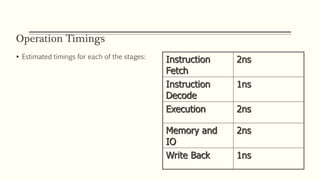
- 35. Operation Timings Estimated timings for each of the stages: Instruction Fetch 2ns Instruction Decode 1ns Execution 2ns Memory and IO 2ns Write Back 1ns
- 36. Advantages/Disadvantages Advantages: More efficient use of processor Quicker time of execution of large number of instructions Disadvantages: Pipelining involves adding hardware to the chip Inability to continuously run the pipeline at full speed because of pipeline hazards which disrupt the smooth execution of the pipeline.
- 37. ANY QUESTIONS?