Edc lab 4 - to implement a half wave rectifier using diode
4 likes679 views
This document describes an electronics lab experiment on implementing a half wave rectifier using a diode. The objectives are to build a half wave rectifier circuit using a diode, load resistance, capacitor, oscilloscope and signal generator. The procedure instructs how to connect the components, observe the rectified output on an oscilloscope, and measure input and output voltages with and without the capacitor. A lab report is required with the circuit diagram, procedure, measurements, equipment list, and expected output graph.
1 of 15


More Related Content
What's hot (20)
Ad
Similar to Edc lab 4 - to implement a half wave rectifier using diode (20)
Ad
More from Tajim Md. Niamat Ullah Akhund (20)
Edc lab 4 - to implement a half wave rectifier using diode
- 1. Electronic Devices and Circuits LAB (IT-2106) 1
- 2. To implement a half wave rectifier using diode. Experiment 4 Tajim 2
- 4. Circuit diagram (connecting oscilloscope) Tajim 4
- 5. Tajim 5
- 6. • A junction/rectifier diode • Load resistance • Electricity capacitor • Oscilloscope • Multimeter • Connecting wires • Breadboard • Signal generator Apparatus Tajim 6
- 7. Oscilloscope A device for viewing oscillations by a display on the screen of a cathode ray tube. Tajim 7
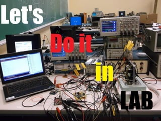
- 11. Procedure Connect the circuit as shown in figure. Observe the rectified output on the oscilloscope. Measure the rms value of the input and output voltages. Remove the capacitor and note the change, if any. Tajim 11
- 12. Expected output for half & full wave rectifier in oscilloscope Tajim 12
- 13. Expected output for half wave rectifier in oscilloscope Tajim 13
- 14. LAB Report 1. LAB report must be hand written. 2. Report on today’s LAB must be submitted on next class individually. 3. LAB report will contain: topic, brief description of the topic, circuit diagram, procedure, data table, equipment list and graph. by Tajim 14
- 15. Tajim 15