SlideShare a Scribd company logo
ELECTRONIC INTERLOCKING
INSTALLATION,TESTING,MAINTANANCE,
PRECOMMISSIONING CHECK LIST ,
PRECAUTIONS AND TROUBLE SHOOTING
Electronic Interlocking -Installation &commissioning
SIP & TOC All Required Materials
and man power IFC and EI Plan
Installation and Wiring
IFC and App.Logic
Design by OEM
FAT with
OEM
Circuit Bell test and other necessary tests
SAT with OEM -- by yard simulator
SAT- by connecting signalling gears in yard
Pre-commissioning Check list with OEM
commissioning of EI system
Data logger validation and MT Testing
Electronic Interlocking -INSTALLATION
Pre-Installation work:
1.obtaining Approved EI Architecture
• Centrailsed
• Distributed
2.Approved Floor plan for
• EI Room
• Power Room
• SM’s OPerating Room
• Battery Room
Electronic Interlocking -INSTALLATION
3.Approved interface circuit
4.Approved SIP and TOC
5. Adequate Meterials
• RDSO/RITES Inspection
• Consignee Inspection
6.Testing Tools
Electronic Interlocking -INSTALLATION
EI Room Installation
Installation of Relay Racks
• Ensuring realay rack is to be insulated from ground
• racks to be erected with necessary suppoting for vibration free
• ladders and the cable trays shall have sufficient space
lateral space b/w cable trays 6 inch
vertical space b/w cable trays 9 inch
Electronic Interlocking -INSTALLATION
Installation of EI Racks
• To be Installed with insulation bush with the floor
• Sufficient space to be provided for opening the equipment door and accessing
the cards and circuit
Installation of VDU Table
• suitable size to be installed for accomodating Dual VDU, Embedded PCs,
DC-DC converter , VDU supply standby arrangement, SM key box,etc
VDU orientation shall be as per SIP
Electronic Interlocking -INSTALLATION
wiring of Relays and EI Euipment
• using standard wire coil with diferent ampacity as per approved interface
circuit
• In all the interface circuits paralleling of contacts to be carried out in
order increase the reliability
• colour codes shall be used as per Railway Pactice for Input , Output, Read
back, Datalogger and internal wiring
• routing of cables from one rack to another rack/EI rack/D/L etc to be
carried out with seperate dedicated cable ducts( like inputs with one duct,
output with another duct , power cables with seperate duct)
Electronic Interlocking -INSTALLATION
• cable Terminaion in Terminals to be done with tag/sleeves (printed/painted)
• spacing between relays shall be carried out for easy view of relay contacts
• Relays to flashed and Tested for contact resistance using Relay Test kit before
inserting in to the jack.this test has to be recorded
Relay Test kit --manual and microcontroller based
• Ensure data logger contact to be front contact to most extent
• Before inserting relays in to jack check all contacts are proprerly inerted and
locked
Electronic Interlocking -INSTALLATION
Circuit wiring Test(Bell Test)
• before pluging relays circuit wiring test to be carried out carefully.
• while carrying the bell test all the EI cards and equipqmnts to be
disconnected
• Bell test to be carried out from relay contact to next contact and from
ternination to next termination.
• Datalogger wiring , power supply wiring and all wirings to be bell tested.
Electronic Interlocking -INSTALLATION
Earthing and Bonding
Electronic Interlocking -INSTALLATION
Wire Component/Bonding Material Size
Main equi-potential earth busbar (MEEB) Copper 300X25X6mm(min.)
Sub equi-potential earth busbar (SEEB) Copper 150X25X6mm(min.)
Individual equipments to SEEB using tinned
copper lugs with stainless steel nut and bolts
Multi-strand single core PVC insulated
coppercableasperIS:694
10Sq.mm.
SEEB to MEEB using tinned copper lugs with
stainless steel nut and bolts.
Multi-strandsinglecorePVC insulated
copper cable as per IS:694
16Sq.mm.
Surge protection devices(SPDs) to MEEB using
tinned copper lugs with stainless steel nut and
bolts.
Multi-strand single core PVC insulated
copper cable as per IS:694
16Sq.mm.
MEEB to main earth electrode Multi-strand single core PVC insulated
copper cable as per IS:694(Duplicated)
35Sq.mm.
Main earth pit to other earth pit in case of loop
earth.
Copper tape OR solid copper round
conductor
25X2mm.or8mm.dia.
Electronic Interlocking -Testing
Testing
• In case of EI, it is carried out by testing integrity of Application Logic
(Software).
• It is possible to carry out this test by using Simulator and Emulator at
factory, drawing office as well as the site as an offline activity.
Interlocking Testing for EI is done in two stages:
a) Factory Acceptance Test (FAT)
b) Site Acceptance Test (SAT)
Electronic Interlocking -Testing
a)FAT Test
•
a) Ensure that the Interlocking system fulfils the station Interlocking & Route
Control Chart requirements and workings in safe manner even if any false
inputs received.
b) Minimises the site errors & risks and reduces the corrections at site. This
results in saving of time at site testing.
• FAT is carried out through simulation set up (using Simulator Panel with toggle
switches or Simulator PC with Interlocking Simulation Setup - software) in which all
field inputs are simulated.
.
Electronic Interlocking -Testing
• During FAT, Timers in Application logic are modified for the FAT testing
reduced from 120 seconds to 12 seconds to speed up the testing.
• In FAT setup, the I/O boards are not physically present and the same are
simulated using the test setup.
• To carry out FAT, the following inputs are required:
a) Signal Interlocking Plan (SIP)
b) Route Control Chart (RCC).
c) Control cum Indication Panel Diagram.
d) Cross Table/Square sheet.
Electronic Interlocking -Testing
• When Railways/Customer testing is completed, the Check sum and CRC values of the
FAT simulated application logic will be recorded
b)Site Acceptance Test (SAT)
• Site testing of Station Interlocking System, where tests are executed at site
environment.
• Ensures
a)all the equipments installed at site are functioning correctly as per approved
system
b)configuration and station interlocking requirements and working in safe manner
and failsafe even if any equipment fails/false inputs/information received
Electronic Interlocking -Testing
To carry out SAT, the following inputs are required:
a) Application source file, Application listing file, Application program file
(Hardcopy & Read-only Softcopy)
b) Station SIP
c) Station Route control chart
d) Station Control cum indication panel diagram
e) Square Sheets/Cross tables
f) Wiring Circuits
Electronic Interlocking -Testing
• All the field inputs are simulated by using simulation panel through toggle
switches
• inputs are sent to EI via relays and the field outputs are sent to lamps
through relays
The following testing shall be carried out while doing SAT:
• Visual test
• Communication testing
• Correspondence Test
• System Integrity Test
• Interlocking testing
• Change over test
Electronic Interlocking -Testing
As explained above SAT is performed in two stages:
1. Testing of Electronic Interlocking at site with E.I. hardware and simulation
panel.
2. Testing of the outdoor gears, viz., points, signals, track circuits, LC gates
etc
Guidelines:
• SAT for EI should be done first from panel and there after from VDU.
• If dual VDU is provided, then SAT to be done with each VDU separately.
Above tests may be under taken using data logger also.
Installation, Testing and commioning  of Electroninc interlocking.pptx
Electronic Interlocking -Testing
Automatic Site Acceptance Test(ASAT)
• carried out to test TOC /SLCT automatically
• uses software which executes Test by simulating the signalling gears
• Test reports will be generated for every route
Electronic Interlocking-Precommissioning Check list
To be carried jointly by OEM and Railway
• M/s Hitachi Rails
• M/s Kyosan
• M/s Medha
• M/s Westrace(Siemens)
Electronic Interlocking -Maintanance
• some periodical and preventive maintenance is necessary to ensure safe and
efficient functioning of the systems.
• The maintenance of Electronic Interlocking System involves the following activities :
(a) Checking of System Power supply.
(b) Visual inspection of the EI system.
(c) Checking of interface relays and cable terminations.
(d) Verification of System changeover from active to standby and vice versa.
(e) Downloading and analysis of user log, event log and error log from Maintenance
Terminal.
(f) Verification of system clock
Electronic Interlocking -Maintanance
(g) Maintenance of earthing and surge protection arrangement.
(h) Checking of communication links between system and peripherals.
(i) Checking the function of peripherals like Operator VDU, Panel Processor etc.
(j) Checking the function of cooling fans in the system racks.
(k) Verification of the Checksum /CRC and version numbers of current software
of the system.
(l) Verification of correct logging of data in external data logger.
(m) Testing the integrity of application program with the help of TOC.
Electronic Interlocking -Maintanance
(a) Checking of System Power supply :
(i) Ensure that the DC –DC converters are in working order.
(ii) Check the fuses for proper housing and tightness.
(iii) Measure the output voltages at DC-DC Converters, fuses and at system
terminals and ensure that they are within the specified limits.
(v) Ensure that standby power supply modules are available and are in working
order.
(b) Visual inspection of the EI system :
(i) Ensure all the PCBs are properly housed and plugged in the system card
file/housing/OC.
(ii) Ensure all the normal indications are available in all PCBs of the system.
Electronic Interlocking -Maintanance
(c) Checking of interface relays and cable terminations :
(i) Ensure proper housing and fixing of Relays and connectors.
(ii) Measure the input and output interface voltages and ensure that they are
withinthe specified limits.
(iii) Check that diodes across the vital output relays are in order.
(iv) Ensure particulars of relays and terminals are available &visible.
(d) Verification of System changeover from active to standby and vice versa :
Where warm standby is available, reset the On line system and see that
change over takes place properly and the stand by system is also working
properly
Electronic Interlocking -Maintanance
(e) Downloading and analysis of user log, event log and error log from
Maintenance Terminal :
(i) Download user data log, event log and error log from the EI system to the
maintenance terminal at regular intervals.
(ii) Analyze the event and error log to identify system faults if any and take
necessary corrective action.
(f) Verification of system clock :
(i) Verify the current time of the system and see that it is correct or not.
(ii) If it is not matching then set the time of the system using maintenance
Terminal.
Electronic Interlocking -Maintanance
(g) Maintenance of Earthing and Surge protection arrangement:
(i) Measure the resistance of the ring/perimeter earth provided for the EI
system and ensure that it is < 1 Ω.
(ii) Check that all the earth electrode connections are properly welded and no
rust formation is there at the terminals and joints.
(iii) Inside the EI equipment room check that all terminations and connections
at the
MEEB, SEEB and at the equipment racks are properly fixed and tightened.
(iv) See that cable armory /shield are connected to earth terminals properly.
(v) Check that all Surge protection devices are connected properly and are in
working order
Electronic Interlocking -Maintanance
(h) Checking of communication links between system and peripherals :
(i) Check that all the communication links between system and peripherals are in
working order.
(ii) Ensure that the power supply and ground connections to the communication
equipment are provided properly.
(i) Checking the function of peripherals like Operator VDU ,Panel Processor etc :
(i) Verify that all field gears can be controlled and operated with the Operator VDU /
CCIP.
(ii) Check that the changeover between Panel & VDU /VDU & standby VDU is taking
place in proper sequence.
(iii) Verify that sufficient backup supply through UPS is available for VDU.
Electronic Interlocking -Maintanance
(j) Checking the function of cooling fans in the system racks :
(i) See that the cooling fans provided inside the system rack are in working
order.
(k) Verification of the Checksum /CRC and version numbers of current
software of the system :
(i) Run the maintenance tool and verify the Checksum, CRC and version of
the current application logic and executive logic.
(ii) See that they are tallying with the past record.
Electronic Interlocking -Maintanance
(l) Verification of correct logging of data in external data logger :
(i) Check the serial communication connections between EI System &
Protocol converter and between Protocol converter & Data logger.
(ii) See that normal indications are available in protocol converter.
(iii) Ensure that the user data log is logging properly in the external data
logger
(m) Testing the integrity of application program with the help of TOC :
(i) This test has to be conducted when ever any modification has been done
in the existing application logic.
(ii) It has to be conducted periodically also to ensure proper functioning of
the existing logic as per the TOC.
Electronic Interlocking -Maintanance
Periodicity of Maintenance
As per the IRSEM general maintenance schedule for Electronic interlocking
is provided for guidance at Annexure: 21-MS3 in Appendix-I the periodicity
of different maintenance tasks for EI for some items are as mentioned
below
Electronic Interlocking -Maintanance
Electronic Interlocking -Trobleshooting
Identifying Faults
The failures occurring in EI systems are broadly divided into two categories. They are
System level faults and Card level faults.
System level faults:
All the faults other than the hard ware failures of system cards can be treated as
system level faults. The system level faults may occur due to problem in any one of
the following sections of the EI system.
(a) System Power supply
(b) Interface wiring
(c) Interface Relays and Relay contacts
(d) System changeover circuit
Electronic Interlocking -Trobleshooting
(e) Panel/VDU
(f) Application logic
(g) Communication equipment
Card level faults
Most of the cards in the EI system are provided with some indications on
the front panel.
These indications reflect the normal or abnormal functioning of the
respective cards.
Electronic Interlocking -Trobleshooting
For the sake of trouble shooting the EI Installation can be divided into the
following sections :
(a) EI System Card file
(b) Peripherals
(c) Interface circuits
(d) Power supply system
(e) Communication cables and equipment
(f) Outdoor gears
(g) Software
Electronic Interlocking -Trobleshooting
Identifying and localization of the fault:
(a) Indications on System Card file
(b) Indications on the CCIP/VDU
(c) User log and Event & Error log in Maintenance Terminal
A general flow chart for trouble shooting the failures in EI system
Installation, Testing and commioning  of Electroninc interlocking.pptx
Electronic Interlocking -Trobleshooting
Electronic Interlocking -Precautions
DO:
1. Tighten the boards after insertion.
2. Ensure all terminations are fully tightened.
3. Place the removed boards with a tag into a conductive shielding bag.
4. Download user data log / Event log / Error log data periodically.
5. Maintain minimum 12V/24V DC at the card file back plane.
6. In case of Warm Standby System Ensure diagnostic switch in “NORMAL”
position before starting the system.
8. Keep the EI room free from dust
Electronic Interlocking -Precautions
Don’t:
1. Reset the system when working.
2. Remove or insert boards, VCOR relays, Fuses / Links and pin connectors when the
system is on.
3. Forcible insertion of the boards in to the slots.
4. Change jumper settings in PCBs.
5. Touch the board components.
6. Repair boards on your own.
7. Alter EI system, Maintenance Terminal and Operator VDU setting without
authorization.
8. Delete / Modify application program Logics without authorization.
9. Use blower for cleaning dust

More Related Content

PDF
Indian Railway Signalling concepts and basics.pdf
DOCX
INDUSTRIAL TRAINING REPORT ON INDIAN RAILWAYS
PPTX
indian railway signal system ppt
PPT
IRS POINT MACHINE.ppt
ODP
Railway signal
PPT
Scada presentation
PPTX
Power System Engineering Training
PPTX
Railway electrification
Indian Railway Signalling concepts and basics.pdf
INDUSTRIAL TRAINING REPORT ON INDIAN RAILWAYS
indian railway signal system ppt
IRS POINT MACHINE.ppt
Railway signal
Scada presentation
Power System Engineering Training
Railway electrification

What's hot (20)

PPTX
3. Concept of pole and zero.pptx
PDF
Handbook on maintenance of digital axle counter
DOCX
Indian railways mechanical vocational training report 1 haxxo24 i~i
PPTX
Signalling System At railway
DOCX
The diesel locomotive
PPTX
WAGON-AIR-BRAKE-SYSTEM.powerpoint.pptx
PPT
Introduction to Railway Signalling
PPT
Telecommunication networks for railways
PDF
Railway Training Report
PPTX
cc ppt Transportation engg poly unit 4(4)
PPTX
Overhead Electrification
PPT
Traction OHE 30.07.2019.ppt
DOC
Basic Control System unit5
PPTX
Indian Railway
PDF
Three phase transformer ( vector groups)
PDF
Project Report (Modern Coach Factory, Raebareli)
PPTX
DOC
Air brake system of locomotives
PPT
Mechanical translational rotational systems and electrical analogous circuit...
PPTX
seminar presentation on summer training at indian railway
3. Concept of pole and zero.pptx
Handbook on maintenance of digital axle counter
Indian railways mechanical vocational training report 1 haxxo24 i~i
Signalling System At railway
The diesel locomotive
WAGON-AIR-BRAKE-SYSTEM.powerpoint.pptx
Introduction to Railway Signalling
Telecommunication networks for railways
Railway Training Report
cc ppt Transportation engg poly unit 4(4)
Overhead Electrification
Traction OHE 30.07.2019.ppt
Basic Control System unit5
Indian Railway
Three phase transformer ( vector groups)
Project Report (Modern Coach Factory, Raebareli)
Air brake system of locomotives
Mechanical translational rotational systems and electrical analogous circuit...
seminar presentation on summer training at indian railway
Ad

Similar to Installation, Testing and commioning of Electroninc interlocking.pptx (20)

DOCX
Interlocking on switchgear principles
PPT
Signalling Maintanance
PPSX
Intertest
PDF
Signalling and telecommunication
PPT
Railroad Industry Connectivity Solutions
PDF
Indian railway signal engg. vol iv
PPT
Model-Based Approaches for Railway Safety, Reliability & Security
PDF
Model-Based Approaches for Railway Safety, Reliability and Security: The Expe...
PPT
PPT
PPTX
Intern PPT on signal and telecommunication
PDF
ITI REPORT HEMANTH
DOC
Nikhil
PDF
150110188-SUBSTATION-AUTOMATION.pdf
DOC
ELECTRICAL INSTALLATION TECHNOLOGY.doc
PDF
Schematic V-TAS Pro application software
PPTX
ABED,FES,JUST,PAUL,SELORM to PRESENT.pptx
PDF
Services interfaces for interoperability of signaling computerinterlocking on...
PDF
Limitless Tech 2
PDF
Railway Industrial Training Report
Interlocking on switchgear principles
Signalling Maintanance
Intertest
Signalling and telecommunication
Railroad Industry Connectivity Solutions
Indian railway signal engg. vol iv
Model-Based Approaches for Railway Safety, Reliability & Security
Model-Based Approaches for Railway Safety, Reliability and Security: The Expe...
Intern PPT on signal and telecommunication
ITI REPORT HEMANTH
Nikhil
150110188-SUBSTATION-AUTOMATION.pdf
ELECTRICAL INSTALLATION TECHNOLOGY.doc
Schematic V-TAS Pro application software
ABED,FES,JUST,PAUL,SELORM to PRESENT.pptx
Services interfaces for interoperability of signaling computerinterlocking on...
Limitless Tech 2
Railway Industrial Training Report
Ad

Recently uploaded (20)

PPTX
Sorting and Hashing in Data Structures with Algorithms, Techniques, Implement...
PDF
Artificial Superintelligence (ASI) Alliance Vision Paper.pdf
PDF
22EC502-MICROCONTROLLER AND INTERFACING-8051 MICROCONTROLLER.pdf
PDF
BIO-INSPIRED ARCHITECTURE FOR PARSIMONIOUS CONVERSATIONAL INTELLIGENCE : THE ...
PPTX
Information Storage and Retrieval Techniques Unit III
PPTX
"Array and Linked List in Data Structures with Types, Operations, Implementat...
PPTX
communication and presentation skills 01
PPTX
Fundamentals of safety and accident prevention -final (1).pptx
PDF
Level 2 – IBM Data and AI Fundamentals (1)_v1.1.PDF
PDF
EXPLORING LEARNING ENGAGEMENT FACTORS INFLUENCING BEHAVIORAL, COGNITIVE, AND ...
PDF
null (2) bgfbg bfgb bfgb fbfg bfbgf b.pdf
PPTX
Graph Data Structures with Types, Traversals, Connectivity, and Real-Life App...
PDF
Design Guidelines and solutions for Plastics parts
PDF
UNIT no 1 INTRODUCTION TO DBMS NOTES.pdf
PDF
PREDICTION OF DIABETES FROM ELECTRONIC HEALTH RECORDS
PDF
A SYSTEMATIC REVIEW OF APPLICATIONS IN FRAUD DETECTION
PPTX
introduction to high performance computing
PDF
Automation-in-Manufacturing-Chapter-Introduction.pdf
PPTX
6ME3A-Unit-II-Sensors and Actuators_Handouts.pptx
PDF
August 2025 - Top 10 Read Articles in Network Security & Its Applications
Sorting and Hashing in Data Structures with Algorithms, Techniques, Implement...
Artificial Superintelligence (ASI) Alliance Vision Paper.pdf
22EC502-MICROCONTROLLER AND INTERFACING-8051 MICROCONTROLLER.pdf
BIO-INSPIRED ARCHITECTURE FOR PARSIMONIOUS CONVERSATIONAL INTELLIGENCE : THE ...
Information Storage and Retrieval Techniques Unit III
"Array and Linked List in Data Structures with Types, Operations, Implementat...
communication and presentation skills 01
Fundamentals of safety and accident prevention -final (1).pptx
Level 2 – IBM Data and AI Fundamentals (1)_v1.1.PDF
EXPLORING LEARNING ENGAGEMENT FACTORS INFLUENCING BEHAVIORAL, COGNITIVE, AND ...
null (2) bgfbg bfgb bfgb fbfg bfbgf b.pdf
Graph Data Structures with Types, Traversals, Connectivity, and Real-Life App...
Design Guidelines and solutions for Plastics parts
UNIT no 1 INTRODUCTION TO DBMS NOTES.pdf
PREDICTION OF DIABETES FROM ELECTRONIC HEALTH RECORDS
A SYSTEMATIC REVIEW OF APPLICATIONS IN FRAUD DETECTION
introduction to high performance computing
Automation-in-Manufacturing-Chapter-Introduction.pdf
6ME3A-Unit-II-Sensors and Actuators_Handouts.pptx
August 2025 - Top 10 Read Articles in Network Security & Its Applications

Installation, Testing and commioning of Electroninc interlocking.pptx

  • 2. Electronic Interlocking -Installation &commissioning SIP & TOC All Required Materials and man power IFC and EI Plan Installation and Wiring IFC and App.Logic Design by OEM FAT with OEM Circuit Bell test and other necessary tests SAT with OEM -- by yard simulator SAT- by connecting signalling gears in yard Pre-commissioning Check list with OEM commissioning of EI system Data logger validation and MT Testing
  • 3. Electronic Interlocking -INSTALLATION Pre-Installation work: 1.obtaining Approved EI Architecture • Centrailsed • Distributed 2.Approved Floor plan for • EI Room • Power Room • SM’s OPerating Room • Battery Room
  • 4. Electronic Interlocking -INSTALLATION 3.Approved interface circuit 4.Approved SIP and TOC 5. Adequate Meterials • RDSO/RITES Inspection • Consignee Inspection 6.Testing Tools
  • 8. Electronic Interlocking -INSTALLATION EI Room Installation Installation of Relay Racks • Ensuring realay rack is to be insulated from ground • racks to be erected with necessary suppoting for vibration free • ladders and the cable trays shall have sufficient space lateral space b/w cable trays 6 inch vertical space b/w cable trays 9 inch
  • 9. Electronic Interlocking -INSTALLATION Installation of EI Racks • To be Installed with insulation bush with the floor • Sufficient space to be provided for opening the equipment door and accessing the cards and circuit Installation of VDU Table • suitable size to be installed for accomodating Dual VDU, Embedded PCs, DC-DC converter , VDU supply standby arrangement, SM key box,etc VDU orientation shall be as per SIP
  • 10. Electronic Interlocking -INSTALLATION wiring of Relays and EI Euipment • using standard wire coil with diferent ampacity as per approved interface circuit • In all the interface circuits paralleling of contacts to be carried out in order increase the reliability • colour codes shall be used as per Railway Pactice for Input , Output, Read back, Datalogger and internal wiring • routing of cables from one rack to another rack/EI rack/D/L etc to be carried out with seperate dedicated cable ducts( like inputs with one duct, output with another duct , power cables with seperate duct)
  • 11. Electronic Interlocking -INSTALLATION • cable Terminaion in Terminals to be done with tag/sleeves (printed/painted) • spacing between relays shall be carried out for easy view of relay contacts • Relays to flashed and Tested for contact resistance using Relay Test kit before inserting in to the jack.this test has to be recorded Relay Test kit --manual and microcontroller based • Ensure data logger contact to be front contact to most extent • Before inserting relays in to jack check all contacts are proprerly inerted and locked
  • 12. Electronic Interlocking -INSTALLATION Circuit wiring Test(Bell Test) • before pluging relays circuit wiring test to be carried out carefully. • while carrying the bell test all the EI cards and equipqmnts to be disconnected • Bell test to be carried out from relay contact to next contact and from ternination to next termination. • Datalogger wiring , power supply wiring and all wirings to be bell tested.
  • 14. Electronic Interlocking -INSTALLATION Wire Component/Bonding Material Size Main equi-potential earth busbar (MEEB) Copper 300X25X6mm(min.) Sub equi-potential earth busbar (SEEB) Copper 150X25X6mm(min.) Individual equipments to SEEB using tinned copper lugs with stainless steel nut and bolts Multi-strand single core PVC insulated coppercableasperIS:694 10Sq.mm. SEEB to MEEB using tinned copper lugs with stainless steel nut and bolts. Multi-strandsinglecorePVC insulated copper cable as per IS:694 16Sq.mm. Surge protection devices(SPDs) to MEEB using tinned copper lugs with stainless steel nut and bolts. Multi-strand single core PVC insulated copper cable as per IS:694 16Sq.mm. MEEB to main earth electrode Multi-strand single core PVC insulated copper cable as per IS:694(Duplicated) 35Sq.mm. Main earth pit to other earth pit in case of loop earth. Copper tape OR solid copper round conductor 25X2mm.or8mm.dia.
  • 15. Electronic Interlocking -Testing Testing • In case of EI, it is carried out by testing integrity of Application Logic (Software). • It is possible to carry out this test by using Simulator and Emulator at factory, drawing office as well as the site as an offline activity. Interlocking Testing for EI is done in two stages: a) Factory Acceptance Test (FAT) b) Site Acceptance Test (SAT)
  • 16. Electronic Interlocking -Testing a)FAT Test • a) Ensure that the Interlocking system fulfils the station Interlocking & Route Control Chart requirements and workings in safe manner even if any false inputs received. b) Minimises the site errors & risks and reduces the corrections at site. This results in saving of time at site testing. • FAT is carried out through simulation set up (using Simulator Panel with toggle switches or Simulator PC with Interlocking Simulation Setup - software) in which all field inputs are simulated. .
  • 18. Electronic Interlocking -Testing • During FAT, Timers in Application logic are modified for the FAT testing reduced from 120 seconds to 12 seconds to speed up the testing. • In FAT setup, the I/O boards are not physically present and the same are simulated using the test setup. • To carry out FAT, the following inputs are required: a) Signal Interlocking Plan (SIP) b) Route Control Chart (RCC). c) Control cum Indication Panel Diagram. d) Cross Table/Square sheet.
  • 19. Electronic Interlocking -Testing • When Railways/Customer testing is completed, the Check sum and CRC values of the FAT simulated application logic will be recorded b)Site Acceptance Test (SAT) • Site testing of Station Interlocking System, where tests are executed at site environment. • Ensures a)all the equipments installed at site are functioning correctly as per approved system b)configuration and station interlocking requirements and working in safe manner and failsafe even if any equipment fails/false inputs/information received
  • 21. Electronic Interlocking -Testing To carry out SAT, the following inputs are required: a) Application source file, Application listing file, Application program file (Hardcopy & Read-only Softcopy) b) Station SIP c) Station Route control chart d) Station Control cum indication panel diagram e) Square Sheets/Cross tables f) Wiring Circuits
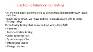
  • 22. Electronic Interlocking -Testing • All the field inputs are simulated by using simulation panel through toggle switches • inputs are sent to EI via relays and the field outputs are sent to lamps through relays The following testing shall be carried out while doing SAT: • Visual test • Communication testing • Correspondence Test • System Integrity Test • Interlocking testing • Change over test
  • 23. Electronic Interlocking -Testing As explained above SAT is performed in two stages: 1. Testing of Electronic Interlocking at site with E.I. hardware and simulation panel. 2. Testing of the outdoor gears, viz., points, signals, track circuits, LC gates etc Guidelines: • SAT for EI should be done first from panel and there after from VDU. • If dual VDU is provided, then SAT to be done with each VDU separately. Above tests may be under taken using data logger also.
  • 26. Electronic Interlocking -Testing Automatic Site Acceptance Test(ASAT) • carried out to test TOC /SLCT automatically • uses software which executes Test by simulating the signalling gears • Test reports will be generated for every route
  • 27. Electronic Interlocking-Precommissioning Check list To be carried jointly by OEM and Railway • M/s Hitachi Rails • M/s Kyosan • M/s Medha • M/s Westrace(Siemens)
  • 28. Electronic Interlocking -Maintanance • some periodical and preventive maintenance is necessary to ensure safe and efficient functioning of the systems. • The maintenance of Electronic Interlocking System involves the following activities : (a) Checking of System Power supply. (b) Visual inspection of the EI system. (c) Checking of interface relays and cable terminations. (d) Verification of System changeover from active to standby and vice versa. (e) Downloading and analysis of user log, event log and error log from Maintenance Terminal. (f) Verification of system clock
  • 29. Electronic Interlocking -Maintanance (g) Maintenance of earthing and surge protection arrangement. (h) Checking of communication links between system and peripherals. (i) Checking the function of peripherals like Operator VDU, Panel Processor etc. (j) Checking the function of cooling fans in the system racks. (k) Verification of the Checksum /CRC and version numbers of current software of the system. (l) Verification of correct logging of data in external data logger. (m) Testing the integrity of application program with the help of TOC.
  • 30. Electronic Interlocking -Maintanance (a) Checking of System Power supply : (i) Ensure that the DC –DC converters are in working order. (ii) Check the fuses for proper housing and tightness. (iii) Measure the output voltages at DC-DC Converters, fuses and at system terminals and ensure that they are within the specified limits. (v) Ensure that standby power supply modules are available and are in working order. (b) Visual inspection of the EI system : (i) Ensure all the PCBs are properly housed and plugged in the system card file/housing/OC. (ii) Ensure all the normal indications are available in all PCBs of the system.
  • 31. Electronic Interlocking -Maintanance (c) Checking of interface relays and cable terminations : (i) Ensure proper housing and fixing of Relays and connectors. (ii) Measure the input and output interface voltages and ensure that they are withinthe specified limits. (iii) Check that diodes across the vital output relays are in order. (iv) Ensure particulars of relays and terminals are available &visible. (d) Verification of System changeover from active to standby and vice versa : Where warm standby is available, reset the On line system and see that change over takes place properly and the stand by system is also working properly
  • 32. Electronic Interlocking -Maintanance (e) Downloading and analysis of user log, event log and error log from Maintenance Terminal : (i) Download user data log, event log and error log from the EI system to the maintenance terminal at regular intervals. (ii) Analyze the event and error log to identify system faults if any and take necessary corrective action. (f) Verification of system clock : (i) Verify the current time of the system and see that it is correct or not. (ii) If it is not matching then set the time of the system using maintenance Terminal.
  • 33. Electronic Interlocking -Maintanance (g) Maintenance of Earthing and Surge protection arrangement: (i) Measure the resistance of the ring/perimeter earth provided for the EI system and ensure that it is < 1 Ω. (ii) Check that all the earth electrode connections are properly welded and no rust formation is there at the terminals and joints. (iii) Inside the EI equipment room check that all terminations and connections at the MEEB, SEEB and at the equipment racks are properly fixed and tightened. (iv) See that cable armory /shield are connected to earth terminals properly. (v) Check that all Surge protection devices are connected properly and are in working order
  • 34. Electronic Interlocking -Maintanance (h) Checking of communication links between system and peripherals : (i) Check that all the communication links between system and peripherals are in working order. (ii) Ensure that the power supply and ground connections to the communication equipment are provided properly. (i) Checking the function of peripherals like Operator VDU ,Panel Processor etc : (i) Verify that all field gears can be controlled and operated with the Operator VDU / CCIP. (ii) Check that the changeover between Panel & VDU /VDU & standby VDU is taking place in proper sequence. (iii) Verify that sufficient backup supply through UPS is available for VDU.
  • 35. Electronic Interlocking -Maintanance (j) Checking the function of cooling fans in the system racks : (i) See that the cooling fans provided inside the system rack are in working order. (k) Verification of the Checksum /CRC and version numbers of current software of the system : (i) Run the maintenance tool and verify the Checksum, CRC and version of the current application logic and executive logic. (ii) See that they are tallying with the past record.
  • 36. Electronic Interlocking -Maintanance (l) Verification of correct logging of data in external data logger : (i) Check the serial communication connections between EI System & Protocol converter and between Protocol converter & Data logger. (ii) See that normal indications are available in protocol converter. (iii) Ensure that the user data log is logging properly in the external data logger (m) Testing the integrity of application program with the help of TOC : (i) This test has to be conducted when ever any modification has been done in the existing application logic. (ii) It has to be conducted periodically also to ensure proper functioning of the existing logic as per the TOC.
  • 37. Electronic Interlocking -Maintanance Periodicity of Maintenance As per the IRSEM general maintenance schedule for Electronic interlocking is provided for guidance at Annexure: 21-MS3 in Appendix-I the periodicity of different maintenance tasks for EI for some items are as mentioned below
  • 39. Electronic Interlocking -Trobleshooting Identifying Faults The failures occurring in EI systems are broadly divided into two categories. They are System level faults and Card level faults. System level faults: All the faults other than the hard ware failures of system cards can be treated as system level faults. The system level faults may occur due to problem in any one of the following sections of the EI system. (a) System Power supply (b) Interface wiring (c) Interface Relays and Relay contacts (d) System changeover circuit
  • 40. Electronic Interlocking -Trobleshooting (e) Panel/VDU (f) Application logic (g) Communication equipment Card level faults Most of the cards in the EI system are provided with some indications on the front panel. These indications reflect the normal or abnormal functioning of the respective cards.
  • 41. Electronic Interlocking -Trobleshooting For the sake of trouble shooting the EI Installation can be divided into the following sections : (a) EI System Card file (b) Peripherals (c) Interface circuits (d) Power supply system (e) Communication cables and equipment (f) Outdoor gears (g) Software
  • 42. Electronic Interlocking -Trobleshooting Identifying and localization of the fault: (a) Indications on System Card file (b) Indications on the CCIP/VDU (c) User log and Event & Error log in Maintenance Terminal A general flow chart for trouble shooting the failures in EI system
  • 45. Electronic Interlocking -Precautions DO: 1. Tighten the boards after insertion. 2. Ensure all terminations are fully tightened. 3. Place the removed boards with a tag into a conductive shielding bag. 4. Download user data log / Event log / Error log data periodically. 5. Maintain minimum 12V/24V DC at the card file back plane. 6. In case of Warm Standby System Ensure diagnostic switch in “NORMAL” position before starting the system. 8. Keep the EI room free from dust
  • 46. Electronic Interlocking -Precautions Don’t: 1. Reset the system when working. 2. Remove or insert boards, VCOR relays, Fuses / Links and pin connectors when the system is on. 3. Forcible insertion of the boards in to the slots. 4. Change jumper settings in PCBs. 5. Touch the board components. 6. Repair boards on your own. 7. Alter EI system, Maintenance Terminal and Operator VDU setting without authorization. 8. Delete / Modify application program Logics without authorization. 9. Use blower for cleaning dust